27
© Munters Corporation, November 2013 QM1084r1 Instruction Manual WF54 Fan with Dragonfly Damper Door Models: WF541VWCD, WF5415VWCD, WF542VWCD WF54 Fan with Dragonfly Damper Door
© Munters Corporation, November 2013 QM1084r1
Instruction Manual
WF54 Fanwith Dragonfl y Damper DoorModels: WF541VWCD, WF5415VWCD, WF542VWCD
WF54 Fan with Dragonfl y Damper Door

© Munters Corporation , November 20132 QM1084r1
WF54 fan with Dragonfly Damper Manual for use and Maintenance
Thank You:Thank you for purchasing a Munters WF54 Fan with Dragonfly Damper. Munters equipment is designed to be the highest performing, highest quality equipment you can buy. With the proper installation and maintenance it will provide many years of service.
Please Note:To achieve maximum performance and insure long life from your Munters product it is essential that it be installed and maintained properly. Please read all instructions carefully before beginning installation.
Warranty:For Warranty claims information see the “Warranty Claims and Return Policy” form QM1021 available from the Munters Corporation office at 1-800-227-2376 or by e-mail at [email protected].
Conditions and Limitations:• Products and Systems involved in a warranty claim under the “Warranty Claims and Return Policy” shall have
been properly installed, maintained and operated under competent supervision, according to the instructions provided by Munters Corporation.
• Malfunction or failure resulting from misuse, abuse, negligence, alteration, accident or lack of proper installation or maintenance shall not be considered a defect under the Warranty.

3© Munters Corporation, November 2013 QM1084r1
Index
Chapters Page
1. Unpacking the Equipment 4
1.1 Parts List
1.2 Fan Dimensions
2. Instalation Instructions 5
3. Electrical Wiring 17
4. Operation 19
5. Maintenance 20
6. Winterizing 22
7. Troubleshooting 23
8. Exploded View and parts list 24
© Munters Corporation , November 20134 QM1084r1
1.1 Parts List
Unpacking the Equipment
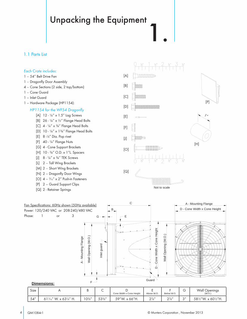
1.Each Crate includes:1 – 54” Belt Drive Fan1 – Dragonfly Door Assembly4 – Cone Sections (2 side, 2 top/bottom)1 – Cone Guard1 – Inlet Guard1 – Hardware Package (HP1154):
HP1154 for the WF54 Dragonfl y[A] 12 - ¼” x 1.5” Lag Screws[B] 26 - ¼” x ½” Flange Head Bolts[C] 4 - ¼” x ¾” Flange Head Bolts[D] 10 - ¼” x 1¾” Flange Head Bolts[E] 8 -1⁄8” Dia. Pop rivet[F] 40 - ¼” Flange Nuts[G] 4 - Cone Support Brackets[H] 10 - ¾” O.D. x 1”L. Spacers[J] 8 - ¼” x ¾” TEK Screws[L] 2 – Tall Wing Brackets[M] 2 – Short Wing Brackets[N] 2 – Dragonfly Door Wings[O] 4 – 5⁄16” x 2” Push-in Fasteners[P] 2 – Guard Support Clips[Q] 2 - Retainer Springs
[A]
[B]
[C]
[D]
[E]
[F]
[J]
[O]
[Q]
[P]
[H]
Fan Specifications: 60Hz shown (50Hz available)Power: 120/240 VAC or 208-240/480 VACPhase: 1 or 3
A - M
ount
ing
Flan
ge
Wal
l Ope
ning
(W.O
.)
FGuard
G E
B
C
D - Cone Width x Cone Height
D -
Con
e W
idth
x C
one
Hei
ght
Wal
l Ope
ning
(W.O
.)
Inle
t gua
rd
A - Mounting Flange
Size A B C D Cone Width x Cone Height
E Above W.O.
F Below W.O.
G Wall Openings (W.O.)
54” 611⁄16” W. x 631⁄4” H. 105⁄8” 533⁄8” 59”W. x 66”H. 27⁄8” 27⁄8” 3” 581⁄2”W. x 601⁄2”H.
Dimensions:
1”
Not to scale

5© Munters Corporation, November 2013 QM1084r1
2.1 INSTALL
Step 1 Construct the framed opening to correct size according to the Wall Opening listed in chart A below.
Installation Instructions
2.
Minimum Spacing'Z'
Chart A
Wall Opening(W. x H.)Fan Dia.
12” recommended; 3½” minimum54” 58½” W. x 60½” H.
Figure 1B 4 x 4 Post Construction - Elevation View
Figure 1A Frame Construction
Ceiling
Framing
H(s
ee c
hart
A)
12"
W (see chart A)
See minimum spacing notes in Chart A
Z
2 x 8 Header boards
4 x 4 or 4 x 6 Posts
2 x 4 Framing
2 x 8 Banner boards
Ceiling
4 x 4 or 4 x 6 Posts
W (see chart A) H
(see
cha
rt A
)
581⁄2” W
4 x 4 or 4 x 6 Posts
Top View
Note: Dragonfly door assembly should be carefully set aside until needed. Do Not stack.Do not remove plastic shipping material from door assembly until installed into fan
© Munters Corporation , November 20136 QM1084r1
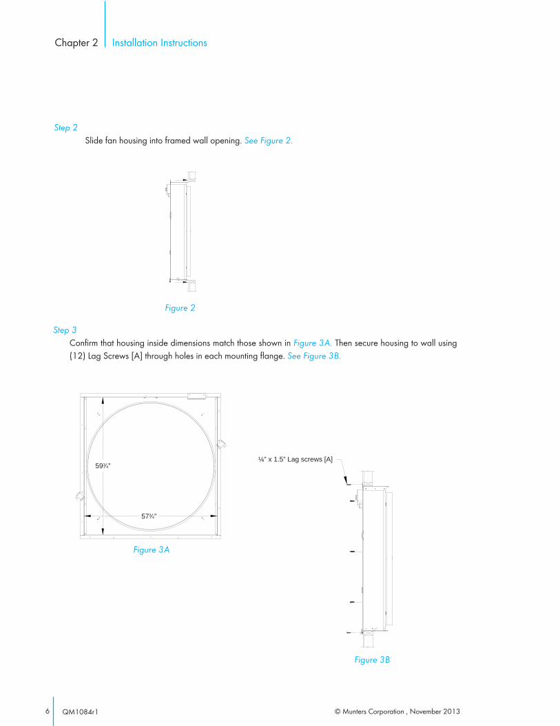
Step 2 Slide fan housing into framed wall opening. See Figure 2.
Figure 2
Installation InstructionsChapter 2
Step 3 Confirm that housing inside dimensions match those shown in Figure 3A. Then secure housing to wall using
(12) Lag Screws [A] through holes in each mounting flange. See Figure 3B.
Figure 3A
Figure 3B
¼” x 1.5” Lag screws [A]593⁄4”
573⁄4”
7© Munters Corporation, November 2013 QM1084r1
Installation InstructionsChapter 2
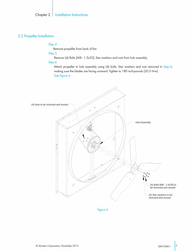
Step 4 Remove propeller from back of fanStep 5 Remove (4) Bolts [M8 - 1.5x25], Star washers and nuts from hub assembly.Step 6 Attach propeller to hub assembly using (4) bolts, Star washers and nuts removed in Step 6,
making sure the blades are facing outward. Tighten to 180 inch-pounds (20.3 N-m). See Figure 4.
Figure 4
(4) Nuts to be removed and reused
Hub Assembly
(4) Bolts [M8 - 1.5x25] to be removed and reused
(4) Star washers to be removed and reused
2.2 Propeller Installation

© Munters Corporation , November 20138 QM1084r1
Step 7 Remove packaging from cone sections and guard.
Step 8 Place all (4) cone sections on a flat surface. See Figure 5. Place (1) support bracket [G] at each joint.
Installation InstructionsChapter 2
Figure 5
Support Bracket [G]
Top/Bottom Section
Side SectionTop/Bottom Section
Side Section
Alignment slot
Drain hole
FH4454
FH4354FH4454
FH4354
Step 9 Join cone sections using (18) of each Bolts [B] and Nuts [F]. Bolts should be installed from the
inside of cone with the nuts on the outside. The bolts in the two holes nearest the small end of each section hold a support bracket. See Figure 6A & 6B.
Step 10 Stand cone sections on edge and curl ends around until they meet, forming a round cone. The
support brackets should be on the outside of cone. Join ends using remaining (6) Bolts [B] and Nuts [F]. Tighten all bolts fully.
Figure 6A
Flange Nut [F]
Support Bracket [G]
Cone Section
Cone Section
¼” x ½” Flange Head Bolts.[B]
Figure 6B
¼" x ½" Bolt [B]
Do not install Damper door into cone yet.NOTICE
NOTE: The fan must be installed in the wall before proceeding with Discharge Cone installation.
2.3 Discharge Cone Installation
9© Munters Corporation, November 2013 QM1084r1
Installation InstructionsChapter 2
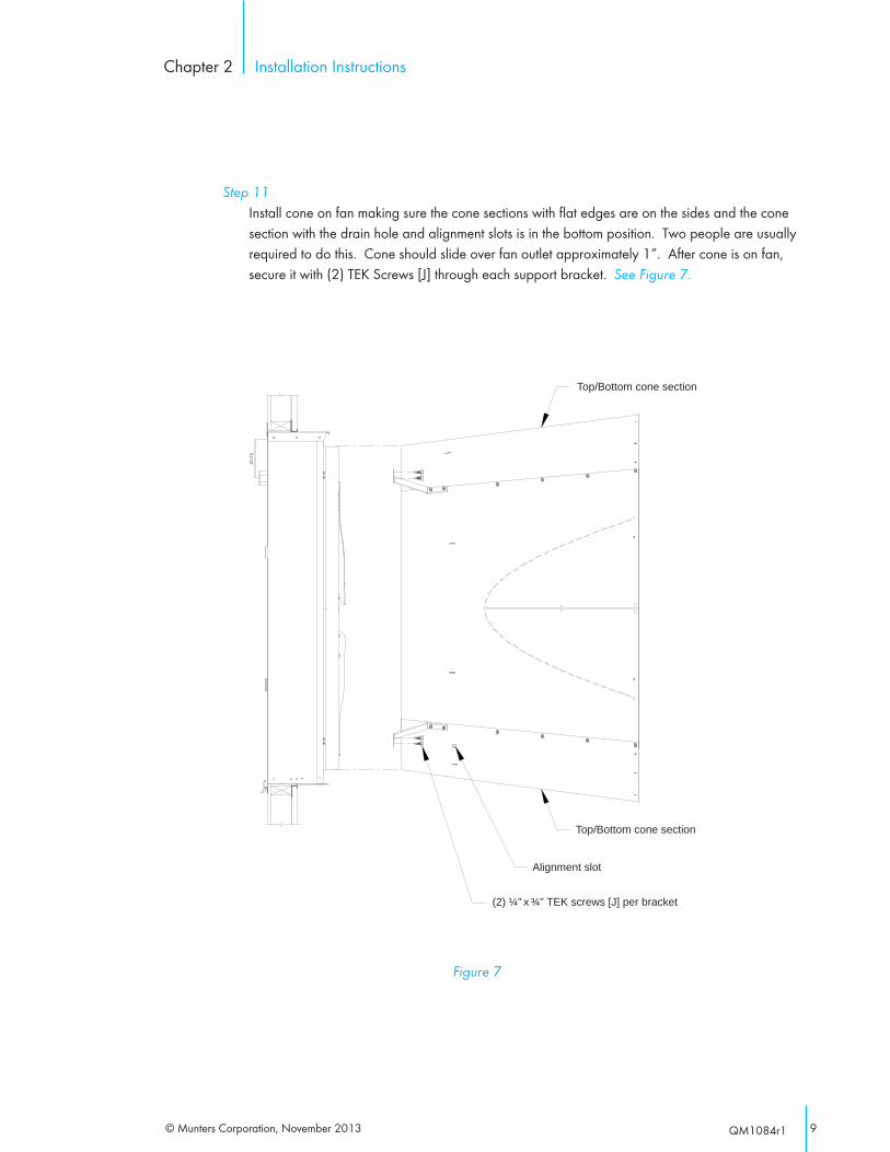
Step 11 Install cone on fan making sure the cone sections with flat edges are on the sides and the cone
section with the drain hole and alignment slots is in the bottom position. Two people are usually required to do this. Cone should slide over fan outlet approximately 1”. After cone is on fan, secure it with (2) TEK Screws [J] through each support bracket. See Figure 7.
Figure 7
(2) ¼" x ¾" TEK screws [J] per bracket
Top/Bottom cone section
Top/Bottom cone section
Alignment slot
© Munters Corporation , November 201310 QM1084r1
Installation InstructionsChapter 2
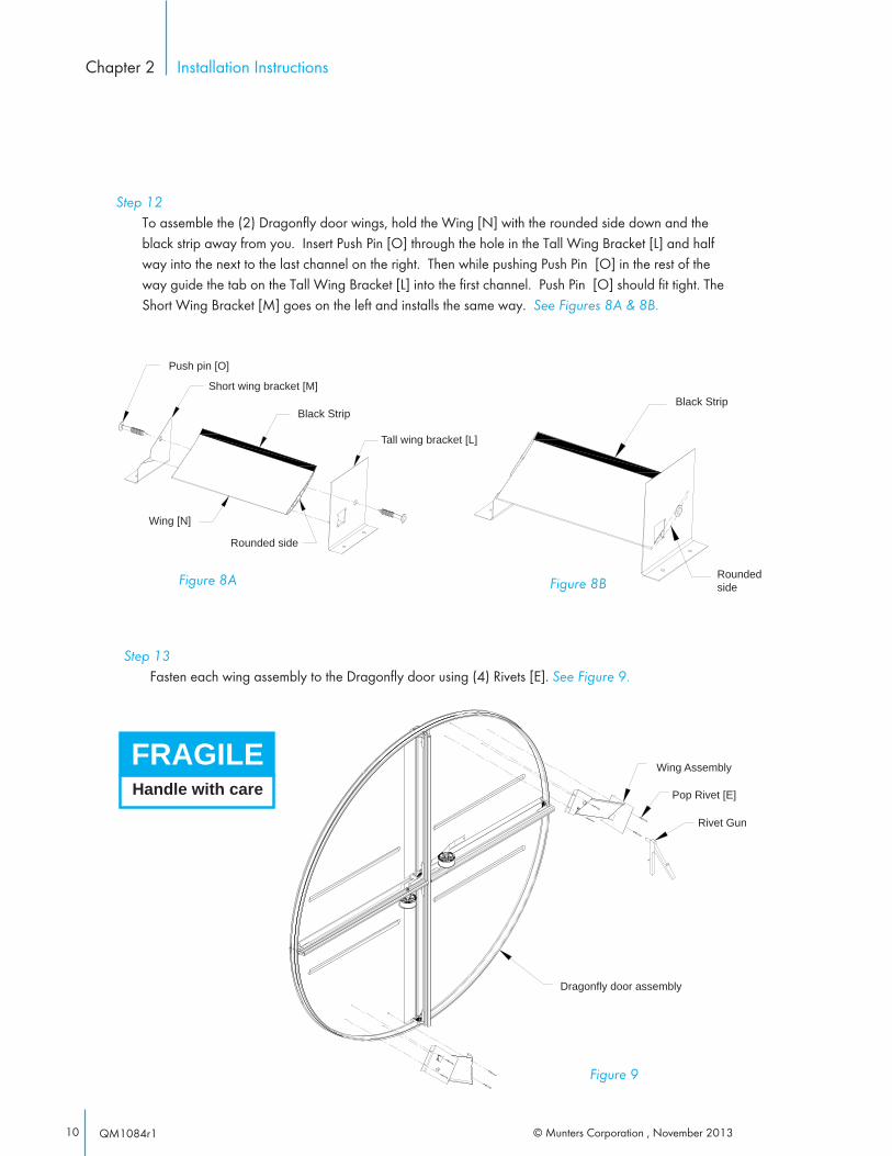
Step 12 To assemble the (2) Dragonfly door wings, hold the Wing [N] with the rounded side down and the
black strip away from you. Insert Push Pin [O] through the hole in the Tall Wing Bracket [L] and half way into the next to the last channel on the right. Then while pushing Push Pin [O] in the rest of the way guide the tab on the Tall Wing Bracket [L] into the first channel. Push Pin [O] should fit tight. The Short Wing Bracket [M] goes on the left and installs the same way. See Figures 8A & 8B.
Figure 8A
Black Strip
Rounded side
Push pin [O]
Wing [N]
Short wing bracket [M]
Tall wing bracket [L]
Figure 8BRounded side
Black Strip
Step 13 Fasten each wing assembly to the Dragonfly door using (4) Rivets [E]. See Figure 9.
Handle with care
FRAGILE Wing Assembly
Pop Rivet [E]
Dragonfly door assembly
Rivet Gun
Figure 9
11© Munters Corporation, November 2013 QM1084r1
Installation InstructionsChapter 2
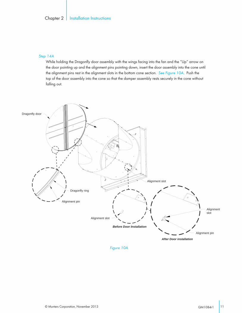
Step 14A While holding the Dragonfly door assembly with the wings facing into the fan and the “Up” arrow on
the door pointing up and the alignment pins pointing down, insert the door assembly into the cone until the alignment pins rest in the alignment slots in the bottom cone section. See Figure 10A. Push the top of the door assembly into the cone so that the damper assembly rests securely in the cone without falling out.
Figure 10A
Alignment pin
Dragonfly door
Dragonfly ring
Before Door Installation
Alignment slot
Alignment slot
Alignment slot
Alignment pin
After Door insIallation

© Munters Corporation , November 201312 QM1084r1
Installation InstructionsChapter 2
Step 14B The door assembly is secured into place with (2) Retainer Springs [Q], one at each upper cone seam.
Working from the back of the fan, the small end of the spring hooks into the Dragonfly Ring seal slot at approximately the 1 o’clock and 11 o’clock position, in line with the cone seam joints. See Figure 10B. While holding the end of the spring with the large “L” shaped end, push the top of the door open slightly and hook the spring in the outer seal slot in the Dragonfly ring, making sure to push the rubber seal aside as spring enters seal slot. See Figure 10B. Repeat for the other spring and position.
Retainer Spring [Q] Rubber seal around outside of ring
Dragonfly door
Retainer Spring [Q]
Dragonfly ring
Rubber seal around outside of ring (cut away to show slot)
Slot into Dragonfly ring
Dragonfly door
Location for retainer spring [Q]
Figure 10B
Step 14C Stretch each spring inward and insert large “L” shaped end of spring into its hole in the cone, between
orifice panel and cone bracket bolts. See Figure 10C.
Figure 10C
Hole for spring in cone seam
Cone seam
13© Munters Corporation, November 2013 QM1084r1
Installation InstructionsChapter 2
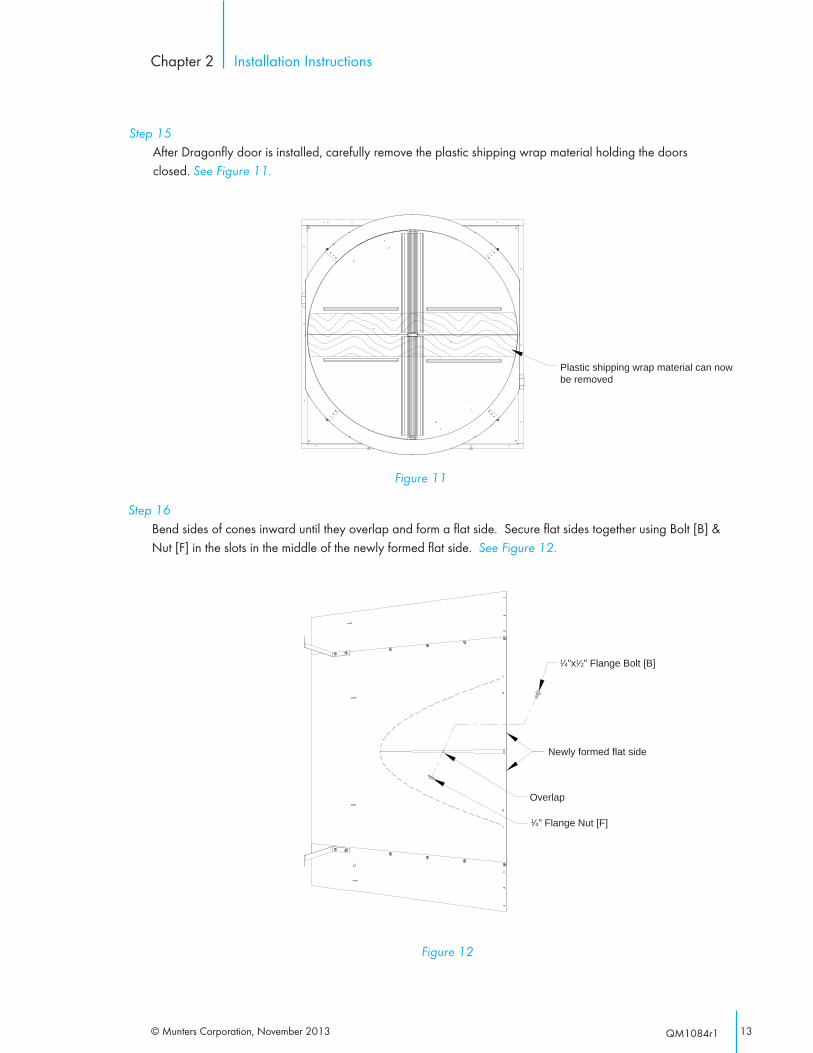
Step 15 After Dragonfly door is installed, carefully remove the plastic shipping wrap material holding the doors
closed. See Figure 11.
Figure 11
Plastic shipping wrap material can now be removed
Step 16 Bend sides of cones inward until they overlap and form a flat side. Secure flat sides together using Bolt [B] &
Nut [F] in the slots in the middle of the newly formed flat side. See Figure 12.
Figure 12
Overlap
Newly formed flat side
1⁄4” Flange Nut [F]
1⁄4”x1⁄2” Flange Bolt [B]
© Munters Corporation , November 201314 QM1084r1
Installation InstructionsChapter 2
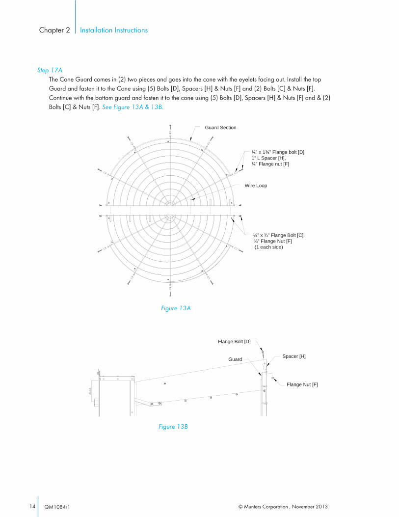
Step 17A The Cone Guard comes in (2) two pieces and goes into the cone with the eyelets facing out. Install the top
Guard and fasten it to the Cone using (5) Bolts [D], Spacers [H] & Nuts [F] and (2) Bolts [C] & Nuts [F]. Continue with the bottom guard and fasten it to the cone using (5) Bolts [D], Spacers [H] & Nuts [F] and & (2) Bolts [C] & Nuts [F]. See Figure 13A & 13B.
Figure 13A
¼” x 1¾” Flange bolt [D], 1” L Spacer [H], ¼” Flange nut [F]
Wire Loop
¼” x 3⁄4” Flange Bolt [C]. 1⁄4” Flange Nut [F] (1 each side)
Guard Section
Figure 13B
Flange Bolt [D]
Guard Spacer [H]
Flange Nut [F]
15© Munters Corporation, November 2013 QM1084r1
Installation InstructionsChapter 2
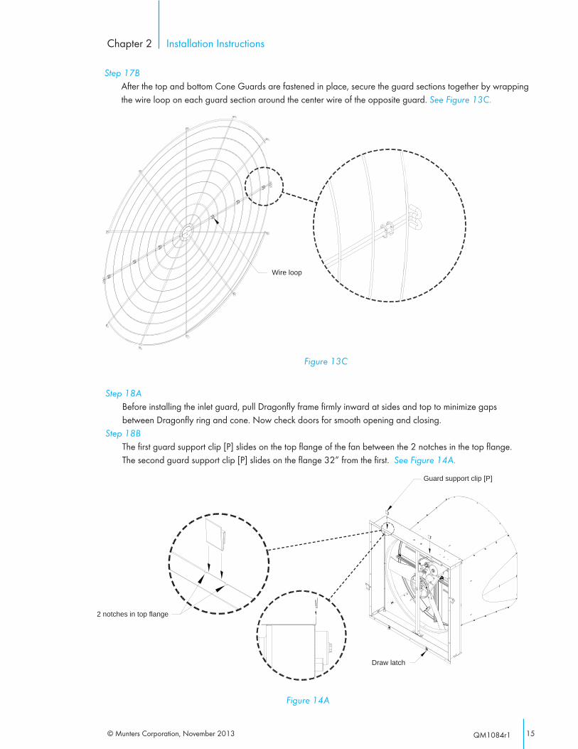
Step 17B After the top and bottom Cone Guards are fastened in place, secure the guard sections together by wrapping
the wire loop on each guard section around the center wire of the opposite guard. See Figure 13C.
Figure 13C
Wire loop
Step 18A Before installing the inlet guard, pull Dragonfly frame firmly inward at sides and top to minimize gaps
between Dragonfly ring and cone. Now check doors for smooth opening and closing. Step 18B The first guard support clip [P] slides on the top flange of the fan between the 2 notches in the top flange.
The second guard support clip [P] slides on the flange 32” from the first. See Figure 14A.
Draw latch
Figure 14A
Guard support clip [P]
2 notches in top flange
© Munters Corporation , November 201316 QM1084r1
Installation InstructionsChapter 2
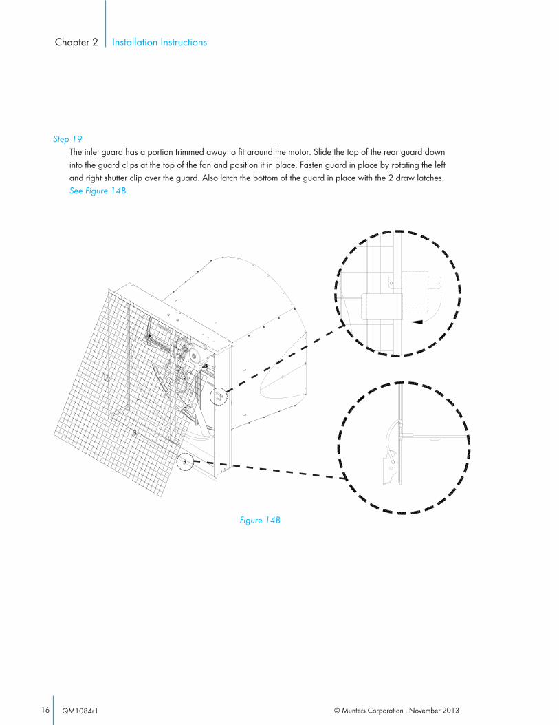
Step 19 The inlet guard has a portion trimmed away to fit around the motor. Slide the top of the rear guard down
into the guard clips at the top of the fan and position it in place. Fasten guard in place by rotating the left and right shutter clip over the guard. Also latch the bottom of the guard in place with the 2 draw latches. See Figure 14B.
Figure 14B

17© Munters Corporation, November 2013 QM1084r1
All wiring should be installed in accordance with National, State, and Local electrical codes. Fans used to ventilate livestock buildings or other rooms where continuous air movement is essential should be connected to individual electrical circuits, with a minimum of two circuits per room. For electrical connection requirements, refer to diagram on motor nameplate and to information enclosed with the Munters environmental control to be used.
Single Phase Fans: motor overload protection should be provided for each fan. A Circuit Breaker Switch or slow blow motor type fuses must be used, See Figure 15A. See form QM1400 for proper size.
Three Phase Fans: motor overload protection should be provided for each fan. A three-pole motor starter or slow blow motor fuses must be used. See Figure 15B.
If a frequency drive (inverter) is used, confirm that motors are rated for inverter duty at the voltage used. The installation of line reactors is recommended to reduce voltage spikes and harmonic distortion. Supplemental motor overload protection is also recommended.
NOTE: A safety cut-off switch should be located adjacent to each fan.
Figure 15ASingle Phase - Motor Overload Protection with Disconnect
(SY2000 or Equivalent)
120 or 240 VAC Power Supply for
Fan
L1 (H)
L2 (N)
G
T1 (H)
T2 (N)
G
120 or 240 VACPower Out
to Fan
L1 (H)
L2 (N)
T1 (H)
T2 (N)
KEY:L1=Line 1L2=Line 2L3=Line 3H=HotN=Neutral G=Ground
NOTE: Information in parenthesis refers to 120 VAC control.
Three Phase Power Supply for
Fan
L1
L2
G
T1
T2
G
Three Phase Power Out
to Fan Motor
L1
L2
T1
T2
L3 T3L3 T3
Figure 15BThree Phase - Motor Overload Protection with Disconnect
Saftey cut-off switchMotor Starter
Electrical Wiring
3.

© Munters Corporation , November 201318 QM1084r1
Electrical WiringChapter 3
Step 1 As the power cable exits the back of the motor form a drip loop and then run cable to power source. See
Figure 16A and 16B.
Drip loop
Figure 16B
Figure 16A
Drip loop
3.2. Recommended Wiring

19© Munters Corporation, November 2013 QM1084r1
1) INITIAL START-UP: With electrical power off, verify that the fan propeller turns freely and that all fasteners are secure. Turn on electrical power and confirm
that the fan operates smoothly.
2) ADJUSTMENTS: Set the fan control to the temperature shown on your Aerotech ventilation system drawing, or to a value which will provide the desired environmental conditions.
Single Phase Fans: Single phase fans are designed for single speed operation only.
If a frequency drive is used, the minimum operating frequency is 30 Hz.Three Phase Fans:
4. Operations
WARNING!
Moving parts, disconnect power before servicing.
Operations
4.
© Munters Corporation , November 201320 QM1084r1
5. Maintenenance
WARNING!
Moving parts, disconnect power before servicing.
WARNING!
High Voltage, disconnect power before servicing.
The following inspection and cleaning procedures should be performed monthly:
Tools Needed for Maintenance:wrenches: 10mm, 13mm, 16mm, 17mm, 27mm, ½", 6mm Hex
1) INSPECT PROPELLER: Check that propeller is secure on drive hub and that there are no signs of damage. The blades are of a self-cleaning design and should not require maintenance.
2) CLEAN regularly for best results:
• FAN MOTOR: Remove any dust accumulation from motor using a brush or cloth. (DO NOT use a pressure washer). A clean motor will run cooler and last longer. At the same time, verify that the motor is secure in its mount.
• DAMPER: Carefully clean dust from damper door and frame so that damper door opens and closes freely. A brush or cloth should be used.
• GUARD: Clean any dust or feathers from fan guards using a brush. Dirty guards can reduce airflow.
3) CHECK FASTENERS: For safety, all fasteners should be inspected. Tighten any loose connections.
4) INSPECT FAN CONTROL: With power disconnected, inspect all electrical connec- tions. Wiring should be secure and in good condition. Remove any dust build-up from control case and sensor using a soft brush or cloth. NEVER CLEAN ELECTRICAL EQUIPMENT WITH A PRESSURE WASHER!
Maintenance
5.
21© Munters Corporation, November 2013 QM1084r1
MaintenanceChapter 5
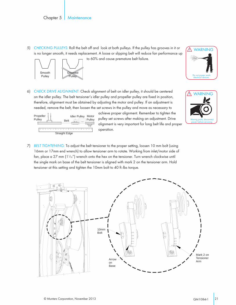
5) CHECKING PULLEYS: Roll the belt off and look at both pulleys. If the pulley has grooves in it or is no longer smooth, it needs replacement. A loose or slipping belt will reduce fan performance up
to 60% and cause premature belt failure.
6) CHECK DRIVE ALIGNMENT: Check alignment of belt on idler pulley, it should be centered on the idler pulley. The belt tensioner’s idler pulley and propeller pulley are fixed in position, therefore, alignment must be obtained by adjusting the motor and pulley. If an adjustment is needed, remove the belt, then loosen the set screws in the pulley and move as necessary to
achieve proper alignment. Remember to tighten the pulley set screws after making an adjustment. Drive alignment is very important for long belt life and proper operation.
7) BELT TIGHTENING: To adjust the belt tensioner to the proper setting, loosen 10 mm bolt (using 16mm or 17mm end wrench) to allow tensioner arm to rotate. Working from inlet/motor side of fan, place a 27 mm (11⁄16”) wrench onto the hex on the tensioner. Turn wrench clockwise until the single mark on base of the belt tensioner is aligned with mark 2 on the tensioner arm. Hold tensioner at this setting and tighten the 10mm bolt to 40 ft.-lbs torque.
SmoothPulley
GroovedPulley
MotorPulley
Straight Edge
BeltIdler PulleyPropeller
Pulley
Arrow on Base
Mark 2 on Tensioner Arm
10mm Bolt
WARNING!
Do not power wash electrical devices.
WARNING!
Moving parts, disconnect power before servicing.
© Munters Corporation , November 201322 QM1084r1
In most climates, it is probable that the ventilation system will never need to operate at a total capacity during the colder winter months. Consequently, it is advisable to “winterize” those fans which will not be used in cold weather to avoid unnecessary heat loss and condensation.
NOTE: At least one single speed fan should be left uncovered and with power available to provide air movement in the event of variable speed control difficulties.
6.1 Winterizing
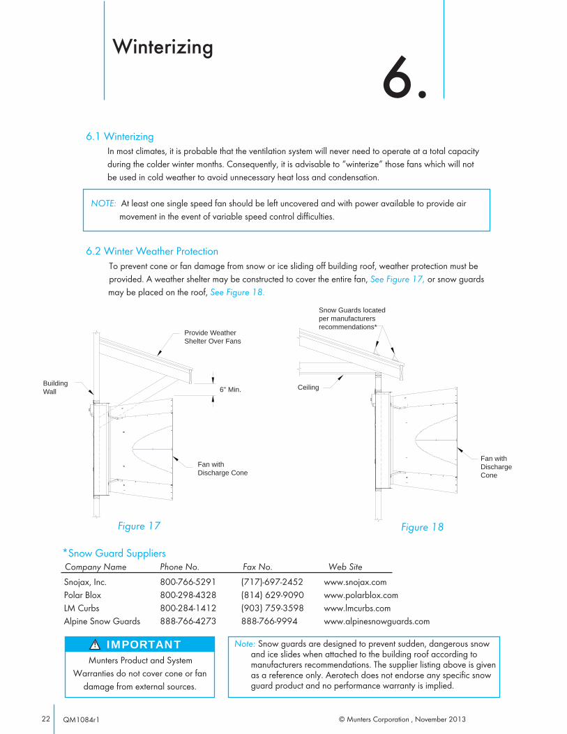
6.2 Winter Weather ProtectionTo prevent cone or fan damage from snow or ice sliding off building roof, weather protection must be provided. A weather shelter may be constructed to cover the entire fan, See Figure 17, or snow guards may be placed on the roof, See Figure 18.
BuildingWall
Provide Weather Shelter Over Fans
6" Min.
Fan withDischarge Cone
Figure 17
Snow Guards located per manufacturers recommendations*
Ceiling
Figure 18
Fan with Discharge Cone
Note: Snow guards are designed to prevent sudden, dangerous snow and ice slides when attached to the building roof according to manufacturers recommendations. The supplier listing above is given as a reference only. Aerotech does not endorse any specific snow guard product and no performance warranty is implied.
Munters Product and System Warranties do not cover cone or fan
damage from external sources.
IMPORTANT!
Snojax, Inc. 800-766-5291 (717)-697-2452 www.snojax.comPolar Blox 800-298-4328 (814) 629-9090 www.polarblox.comLM Curbs 800-284-1412 (903) 759-3598 www.lmcurbs.comAlpine Snow Guards 888-766-4273 888-766-9994 www.alpinesnowguards.com
*Snow Guard Suppliers Company Name Phone No. Fax No. Web Site
Winterizing
6.
23© Munters Corporation, November 2013 QM1084r1
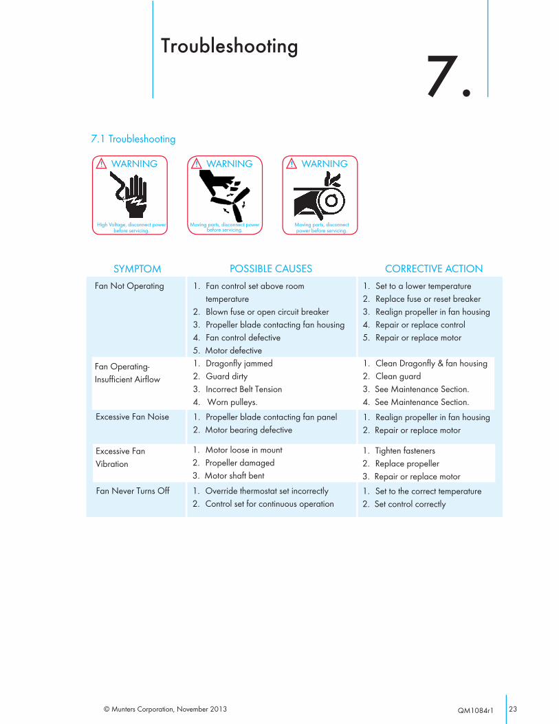
7.1 Troubleshooting
WARNING!
High Voltage, disconnect power before servicing.
WARNING!
Moving parts, disconnect power before servicing.
WARNING!
Moving parts, disconnect power before servicing.
Excessive Fan Noise
1. Fan control set above room temperature2. Blown fuse or open circuit breaker3. Propeller blade contacting fan housing4. Fan control defective5. Motor defective
1. Propeller blade contacting fan panel2. Motor bearing defective
1. Set to a lower temperature2. Replace fuse or reset breaker3. Realign propeller in fan housing4. Repair or replace control5. Repair or replace motor
1. Realign propeller in fan housing2. Repair or replace motor
Fan Not Operating
SYMPTOM POSSIBLE CAUSES CORRECTIVE ACTION
Fan Never Turns Off 1. Override thermostat set incorrectly2. Control set for continuous operation
1. Set to the correct temperature2. Set control correctly
1. Dragonfly jammed2. Guard dirty3. Incorrect Belt Tension4. Worn pulleys.
1. Clean Dragonfly & fan housing2. Clean guard3. See Maintenance Section.4. See Maintenance Section.
Fan Operating-Insufficient Airflow
Excessive FanVibration
1. Motor loose in mount2. Propeller damaged3. Motor shaft bent
1. Tighten fasteners2. Replace propeller3. Repair or replace motor
Troubleshooting
7.

© Munters Corporation , November 201324 QM1084r1
Exploded View 8.
25© Munters Corporation, November 2013 QM1084r1
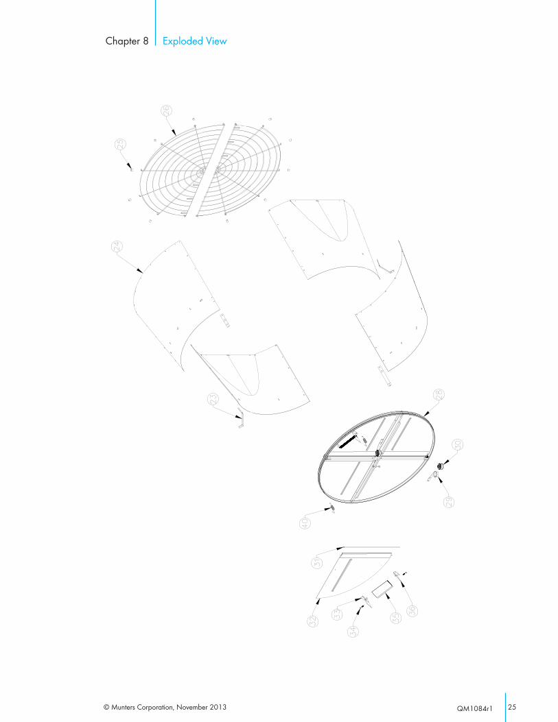
Exploded ViewChapter 8
© Munters Corporation , November 201326 QM1084r1
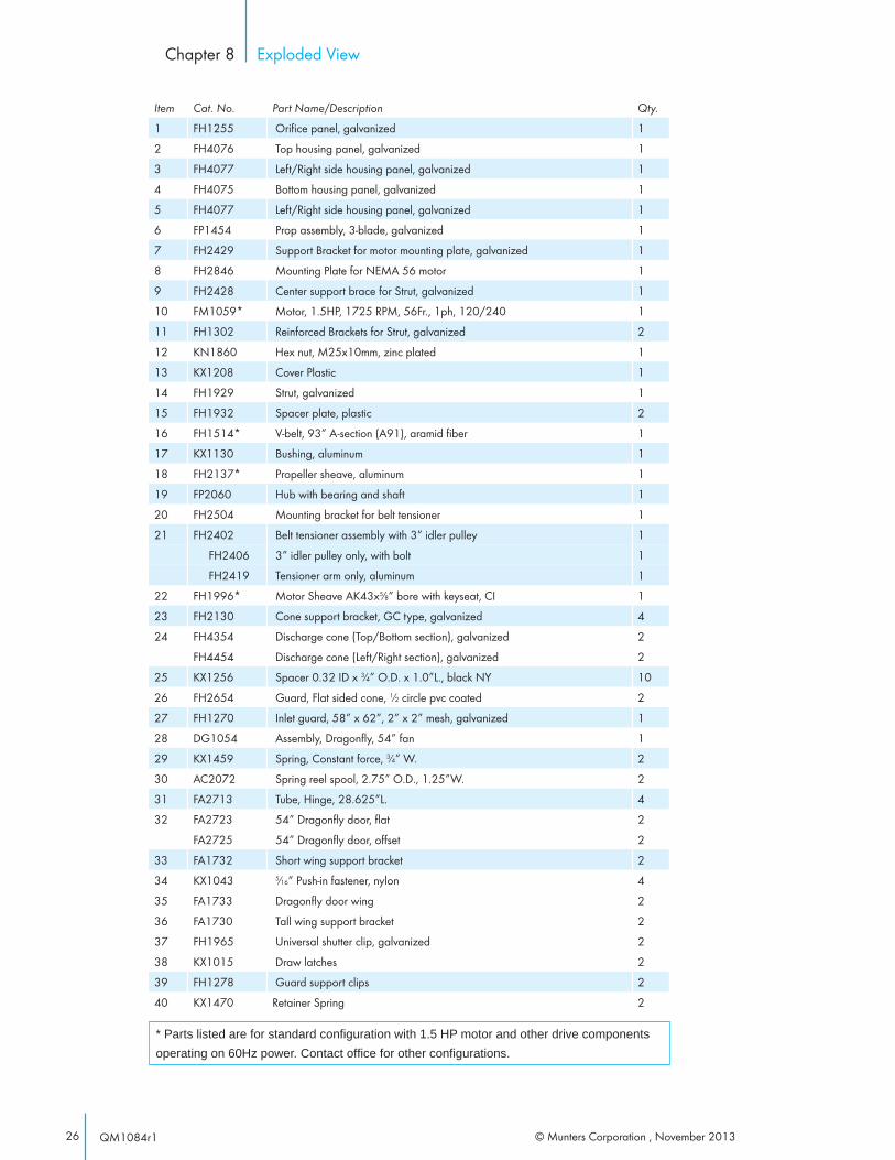
Exploded ViewChapter 8
Item Cat. No. Part Name/Description Qty.
1 FH1255 Orifi ce panel, galvanized 1
2 FH4076 Top housing panel, galvanized 1
3 FH4077 Left/Right side housing panel, galvanized 1
4 FH4075 Bottom housing panel, galvanized 1
5 FH4077 Left/Right side housing panel, galvanized 1
6 FP1454 Prop assembly, 3-blade, galvanized 1
7 FH2429 Support Bracket for motor mounting plate, galvanized 1
8 FH2846 Mounting Plate for NEMA 56 motor 1
9 FH2428 Center support brace for Strut, galvanized 1
10 FM1059* Motor, 1.5HP, 1725 RPM, 56Fr., 1ph, 120/240 1
11 FH1302 Reinforced Brackets for Strut, galvanized 2
12 KN1860 Hex nut, M25x10mm, zinc plated 1
13 KX1208 Cover Plastic 1
14 FH1929 Strut, galvanized 1
15 FH1932 Spacer plate, plastic 2
16 FH1514* V-belt, 93” A-section (A91), aramid fi ber 1
17 KX1130 Bushing, aluminum 1
18 FH2137* Propeller sheave, aluminum 1
19 FP2060 Hub with bearing and shaft 1
20 FH2504 Mounting bracket for belt tensioner 1
21 FH2402 Belt tensioner assembly with 3” idler pulley 1
FH2406 3” idler pulley only, with bolt 1
FH2419 Tensioner arm only, aluminum 1
22 FH1996* Motor Sheave AK43x5⁄8” bore with keyseat, CI 1
23 FH2130 Cone support bracket, GC type, galvanized 4
24 FH4354 Discharge cone (Top/Bottom section), galvanized 2
FH4454 Discharge cone (Left/Right section), galvanized 2
25 KX1256 Spacer 0.32 ID x 3⁄4” O.D. x 1.0”L., black NY 10
26 FH2654 Guard, Flat sided cone, 1⁄2 circle pvc coated 2
27 FH1270 Inlet guard, 58” x 62”, 2” x 2” mesh, galvanized 1
28 DG1054 Assembly, Dragonfl y, 54” fan 1
29 KX1459 Spring, Constant force, 3⁄4” W. 2
30 AC2072 Spring reel spool, 2.75” O.D., 1.25”W. 2
31 FA2713 Tube, Hinge, 28.625”L. 4
32 FA2723 54” Dragonfl y door, fl at 2
FA2725 54” Dragonfl y door, off set 2
33 FA1732 Short wing support bracket 2
34 KX1043 5⁄16” Push-in fastener, nylon 4
35 FA1733 Dragonfl y door wing 2
36 FA1730 Tall wing support bracket 2
37 FH1965 Universal shutter clip, galvanized 2
38 KX1015 Draw latches 2
39 FH1278 Guard support clips 2
40 KX1470 Retainer Spring 2
* Parts listed are for standard confi guration with 1.5 HP motor and other drive components operating on 60Hz power. Contact offi ce for other confi gurations.

27© Munters Corporation, November 2013 QM1084r1
Munters Europe AB, Isafjordsgatan 1, P.O. Box 1150, SE-164 26 Kista, Sweden. Phone +46 08 626 63 00, Fax +46 8 754 56 66.
Munters Corporation 4215 Legion Drive Mason, MI 48854-1036 U.S.A. Phone +1 800-227-2376, Fax +1 517-676-7078
www.munters.us/aghort
Australia Munters Pty Limited, Phone +61 2 6025 6422, Brazil Munters Brasil Industria e Comercio Ltda, Phone +55 41 3317 5050, Canada/US MuntersCorporation Mason, MI Phone +1 517 676 7070, China Munters Air Treatment Equipment (Beijing) Co. Ltd, Phone +86 10 80 481 121, Denmark Munters A/S, Phone +45 9862 3311, India Munters India, Phone +91 20 3052 2520, Indonesia Munters, Phone +62 818 739 235, Italy Munters Italy S.p.A., Chiusavecchia, Phone +39 0183 52 11, Japan Munters K.K., Phone +81 3 5970 0021, Korea Munters Korea Co. Ltd., Phone +82 2 761 8701, Mexico Munters Mexico, Phone +52 818 262 54 00, Russia Munters AB, Phone +7 812 448 5740, Singapore Munters Pte Ltd., Phone +65 744 6828, South Africa and Sub-Sahara Countries Munters (Pty) Ltd., Phone +27 11 997 2000, Spain Munters Spain S.A., Phone +34 91 640 09 02, Sweden Munters AB, Phone +46 8 626 63 00, Thailand Munters Co. Ltd., Phone +66 2 642 2670, Turkey Munters Form Endüstri Sistemleri A.Ş, Phone +90 322 231 1338, USA Munters Corporation Mason, MI Phone +1 517 676 7070, Vietnam Munters Vietnam, Phone +84 8 3825 6838, Export & Other countries Munters Italy S.p.A., Chiusavecchia Phone +39 0183 52 11
WF Dragonfl y with Damper Door is developed and produced by Munters Corporation, Mason, Michigan U.S.A. 1-800-227-2376


