212 WGK WGK Vtee Water cooled water chillers The water chiller WGK series are suitable for large chilled water production in applications like shopping centers, of- fice buildings and industrial processes. They are extreme easy installation and maintenance; The use of screw, semi- hermetic bi-rotor compressors and the use capacity control system allows to give always the correct cooling capacity to the plant. This solution optimizes the efficiency also with partial loads and guaranties the maximum energy saving in all working conditions. These units are available in different versions in order to adjust their performances to the specific system requirements. VERSIONS LS Low noise version. EV Condenserless version. HW Reversible version on the hydraulic circuit. RP Cooling only version with partial heat recovery. RT Cooling only version with total heat recovery. BT Cooling only version for low user water temperature. ACCESSORIES INSE Serial interface card RS485. KAVG Rubber anti-vibration mountings. KAVM Spring anti-vibration mountings. MAML Refrigerant circuit pressure gauges. MOCO Compressors stepless control. MVCS Compressors suction manual valves. PCRL Remote control panel. PFCS Power factor correction system cosf > 0,9. RAEV Evaporator antifreeze heater. RP00 Partial heat recovery. V2M0 Source 4÷20 mA modulating valve. VSLI Liquid line solenoid valve. VTEE Electronic expansion valve.
Transcript
212
wGK
wGK
VteeINVERTER
water cooled water chillers
The water chiller WGK series are suitable for large chilled water production in applications like shopping centers, of-fice buildings and industrial processes. They are extreme easy installation and maintenance; The use of screw, semi-hermetic bi-rotor compressors and the use capacity control system allows to give always the correct cooling capacity to the plant. This solution optimizes the efficiency also with partial loads and guaranties the maximum energy saving in all working conditions. These units are available in different versions in order to adjust their performances to the specific system requirements.
VERSIONS
LS Low noise version.EV Condenserless version.Hw Reversible version on the hydraulic circuit.RP Cooling only version with partial heat recovery.RT Cooling only version with total heat recovery.BT Cooling only version for low user water temperature.
ACCESSORIES
INSE Serial interface card RS485.KAVG Rubber anti-vibration mountings.KAVM Spring anti-vibration mountings.MAML Refrigerant circuit pressure gauges.MOCO Compressors stepless control.MVCS Compressors suction manual valves.PCRL Remote control panel.PFCS Power factor correction system cosf > 0,9.RAEV Evaporator antifreeze heater.RP00 Partial heat recovery.V2M0 Source 4÷20 mA modulating valve.VSLI Liquid line solenoid valve.VTEE Electronic expansion valve.
Power supplyPeak currentMaximum input currentCompressors / CircuitsSound power standard version (3)
Sound pressure standard version (4)
Sound power LS version (3)
Sound pressure LS version (4)
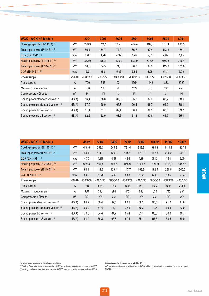
Performances are referred to the following conditions:(1) Cooling: Evaporator water temperature in/out 12/7°C condenser water temperature in/out 30/35°C. (2) Heating: condenser water temperature in/out 30/35°C; evaporator water temperature in/out 10/7°C.
(3) Sound power level in accordance with ISO 3744.(4) Sound pressure level at 10 mt from the unit in free field conditions direction factor Q = 2 in accordance with ISO 3744.
wGK - wGK/HP ModelsCooling capacity (EN14511) (1)
Total input power (EN14511)(1)
EER (EN14511) (1)
Heating capacity (EN14511) (2)
Total input power (EN14511)(2)
COP (EN14511) (2)
Power supplyPeak currentMaximum input currentCompressors / CircuitsSound power standard version (3)
Peak currentMax input currentPower supplyCompressors / CircuitsSound power level (3)
Sound pressure level (4)
Sound power LS version (3)
Sound pressure LS version (4)
wGK/EV ModelsCooling capacity (5)
Total input power (5)
Water flow (5)
Peak currentMax input currentPower supplyCompressors / CircuitsSound power level (3)
Sound pressure level (4)
Sound power LS version (3)
Sound pressure LS version (4)
Performances are referred to the following conditions:(5)For EV version: condensing temperature 50 °C, water temperature in/out 12/7 °C.(3)Sound power level in accordance with ISO 3744.
(4) Sound pressure level at 10 mt from the unit in free field conditions direction factor Q = 2 in accordance with ISO 3744.
OPERATION LIMITS
User
wate
r outl
et tem
pera
ture (
°C)
Source water inlet temperature (°C) Source water outlet temperature (°C)
User
wate
r inlet
temp
eratu
re (°
C)
Only HW, RP, RT versions All versions Only BT versions (working mode with glycol)
215 www.hidros.eu215 www.hidros.eu
wGK
water circuit. They are made with high per-formance special copper pipes, externally finned and internally grooved to increase the heating exchange coefficient, keeping a low fouling factor. They are equipped with Victaulic joints and they could be hydrau-lically connected to well or cooling tower water systems.
EVAPORATORS The evaporators are shell and tube type, dry expansions, with one or two refriger-ant circuits and one water circuit. Made with pure electrolytic copper tubes, tubes plate made in carbon steel, it is insulated by close-cell polyurethane foam material and external UV ray-proof scratch jacket. Some plastic and corrosion-proof baffles are suitably placed inside the shell, allow-ing a correct water distribution and making the tube bundle particularly strong and vi-bration-free, also in case of very high water flows. The evaporators are also equipped with safety water flow switch switching off the unit in case of low water flow and with Victaulic joints. Exchanger design pressure water side: 10 bar.
MICROPROCESSORSAll units are supplied as standard with mi-croprocessor controls. The microprocessor controls the following functions: control of the water temperature, antifreeze protec-tion, compressor timing, compressor au-tomatic starting sequence, alarm reset, volt free contact for remote general alarm, alarms and operation LED’s. If required (available as an option), the microproces-sor can be configuredin order for it to con-nect to a site BMS system thus enabling remote control and management. The tech-nical department can discuss and evaluate, in conjunction with the customer, solutions using MODBUS protocols.
ELECTRICS ENCLOSURE The enclosure is manufactured in order to comply with the requirements of the elec-tromagnetic compatibility standards CEE 73/23 and 89/336. Access to the enclosure is achieved by removing the front panel of the unit. The following components are sup-plied as standard on all units: main switch, thermal overloads (protection of pumps - if present - and fans), compressor fuses, con-trol circuit automatic breakers, compressor
FRAME All units are made from hot-galvanized sheet steel, painted with polyurethane powder enamel and stowed at 180°C to provide maximum protection against corro-sion. The frame is self-supporting, Strong and compact, made of bended steel pro-files (color RAL 9004-black), supporting the heat exchangers and on which all the main components are installed at sight. On request, the compressors can be isolated by a soundproofing cabinet and mufflers on compressors discharge (Version LS).
REFRIGERANT CIRCUIT The refrigerant used in these units is R134a. The refrigerant circuit is assembled us-ing internationally recognized brand name components with all brazing and welding being performed in accordance with ISO 97/23. Each refrigerant circuit is totally in-dependent from the other. Failure of one circuit does not influence the other circuit. The refrigerant circuit is made of copper or carbon steel tube, equipped with electronic expansion valve, dehydrating filter with in-terchangeable cartridges, sight glass, high and low pressure safety device, high and low pressure switches, high and low pres-sure gauges, shut-off valve on liquid line, in-built one way valve on compressor dis-charge side.
COMPRESSORS Compressors are Semi-hermetic screw type, equipped with capacity steps, mo-tor thermal protection, control of the rota-tion sense, oil crankcase heater, shut-off valve on discharge side and anti-vibration mountings. The compressors lubrication is of forced type, with no pump and in order to prevent many oil migrations to the cooling circuit, the compressors are provided with an oil separator, in-built to the discharge side, an optical electronic pressure switch for checking the oil level. The electrical mo-tor is provided with an automatic system for partial load start and for mechanical lock of the inrush remote control switches, so to avoid accidental short-circuits. The cooling capacity could be regulated by steps (stand-ard) or stepless modulation (Optional).
CONDENSERS The Shell and tube condensers are shell and tube type, with single refrigerant and
contactors, fan contactors and pump con-tactors. The terminal board has volt free contacts for remote ON-OFF, Summer/Winter change over (reversible versions only) and general alarm. For all three phase units, a sequence relay that disables the power supply in the event that the phase sequence is incorrect (screw compressors can be damaged if they rotate in the wrong direction), is fitted as standard.
CONTROL AND PROTECTION DEVICESAll units are supplied with the following control and protection devices: Return water temperature sensor installed on the return water line from the building (12°C), antifreeze protection sensor installed on the outlet water temperature (7°C), high pressure switch with manual reset, low pressure switch with automatic reset, high pressure safety valve, compressor thermal overload protection, fans thermal overload protection and flow switch.
216
wGK
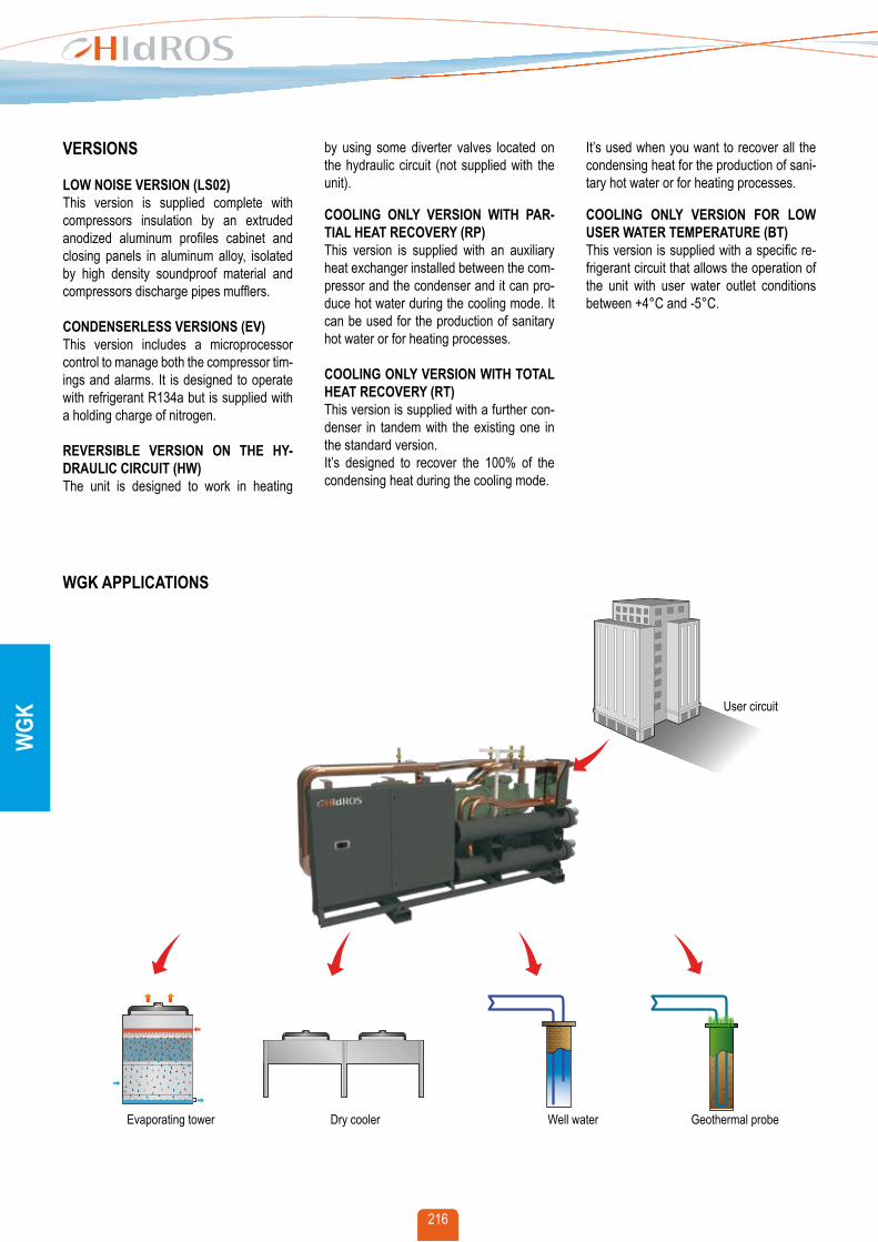
by using some diverter valves located on the hydraulic circuit (not supplied with the unit).
COOLING ONLy VERSION wITH PAR-TIAL HEAT RECOVERy (RP)This version is supplied with an auxiliary heat exchanger installed between the com-pressor and the condenser and it can pro-duce hot water during the cooling mode. It can be used for the production of sanitary hot water or for heating processes.
COOLING ONLy VERSION wITH TOTAL HEAT RECOVERy (RT)This version is supplied with a further con-denser in tandem with the existing one in the standard version. It’s designed to recover the 100% of the condensing heat during the cooling mode.
VERSIONS
LOw NOISE VERSION (LS02)This version is supplied complete with compressors insulation by an extruded anodized aluminum profiles cabinet and closing panels in aluminum alloy, isolated by high density soundproof material and compressors discharge pipes mufflers.
CONDENSERLESS VERSIONS (EV)This version includes a microprocessor control to manage both the compressor tim-ings and alarms. It is designed to operate with refrigerant R134a but is supplied with a holding charge of nitrogen.
REVERSIBLE VERSION ON THE Hy-DRAULIC CIRCUIT (Hw)The unit is designed to work in heating
It’s used when you want to recover all the condensing heat for the production of sani-tary hot water or for heating processes.
COOLING ONLy VERSION FOR LOw USER wATER TEMPERATURE (BT)This version is supplied with a specific re-frigerant circuit that allows the operation of the unit with user water outlet conditions between +4°C and -5°C.
Evaporating tower Dry cooler Well water Geothermal probe


![[ e„wËÔi †M‡RU ] of SSC-2015/308 cvZv-1 [ e„wËÔi †M‡RU ] gva¨wgK I D”P gva¨wgK wk v †evW, PÆMvg 2015 mv‡ji gva¨wgK ¯‹zj mvwUwd‡KU cix vi djvd‡ji wfwˇZ](https://static.documents.pub/doc/80x56/5aae70db7f8b9aa8438c197a/-ewi-mru-of-ssc-2015308-cvzv-1-ewi-mru-gvawgk-i-dp.jpg)
![[ e„wËÔi †M‡RU ] · [ e„wËÔi †M‡RU ] gva¨wgK I D”P gva¨wgK wk¶v †evW©, PÆMÖvg 2017 mv‡ji gva¨wgK ¯‹zj mvwU©wd‡KU cix¶vi djvd‡ji wfwˇZ](https://static.documents.pub/doc/80x56/5ec41719e2fbf52ed91cd80c/-eawi-amaru-eawi-amaru-gvawgk-i-dap-gvawgk-wkv.jpg)


![[ e„wËÔi †M‡RU ]...BOARD OF INTERMEDIATE & SECONDARY EDUCATION,CHITTAGONG LIST OF STUDENTS FOR STIPEND OF JSC-2014 Scholarship Results of JSC-2014 cvZv-1 gva¨wgK I D”P gva¨wgK](https://static.documents.pub/doc/80x56/5f0351b97e708231d408a02c/-eawi-amaru-board-of-intermediate-secondary-educationchittagong.jpg)
![[ e„wËÕi †M‡RU ] · Scholarship of SSC-2018 cvZv-1 [ e„wËÕi †M‡RU ] gva¨wgK I D”P gva¨wgK wk¶v †evW, PÆMvg 2018 mv‡ji gva¨wgK ¯‹zj mvwUwd‡KU cix¶vi](https://static.documents.pub/doc/80x56/604d209ddbd99e320d1d29b0/-eawi-amaru-scholarship-of-ssc-2018-cvzv-1-eawi-amaru-.jpg)
![[ e„wËÔi †M‡RU ]€¦ · Scholarship of SSC-2014/308 cvZv-1 [ e„wËÔi †M‡RU ] gva¨wgK I D”P gva¨wgK wk¶v †evW©, PÆMÖvg 2014 mv‡ji gva¨wgK ¯‹zj mvwU©wd‡KU](https://static.documents.pub/doc/80x56/5fac70ef0726a55c9e71826a/-eawi-amaru-scholarship-of-ssc-2014308-cvzv-1-eawi-amaru.jpg)


