14
UNIVERSITY OF TEXAS AT SAN ANTONIO White Noise Generator Circuitry and Analysis David Sanchez 8/4/2008
| Date post: | 06-Mar-2018 |
| Category: |
Documents |
| Upload: | phungxuyen |
| View: | 221 times |
| Download: | 3 times |

UNIVERSITY OF TEXAS AT SAN ANTONIO
White Noise Generator Circuitry and Analysis
David Sanchez
8/4/2008

Electronic Circuits II Project – White Noise Generator Page 2
Table of Contents Introduction .................................................................................................................................................. 3
Overview of the Circuit ................................................................................................................................ 3
Circuit Subsets .............................................................................................................................................. 4
Noise Generation Stage ........................................................................................................................ 4
Amplification of the Noise Signal .......................................................................................................... 6
Active Low-Pass Filter ........................................................................................................................... 7
Audio Output Stage............................................................................................................................... 8
Analysis ......................................................................................................................................................... 9
Discussion ................................................................................................................................................... 11
Conclusion .................................................................................................................................................. 12
Works Cited ................................................................................................................................................ 13
Electronic Circuits II Project – White Noise Generator Page 3
Introduction
A white noise generator is just that – a circuit that produces white noise. White noise
is essentially just distortion whose amplitude is constant through a wide frequency
range. It is often produced by a random noise generator in which all frequencies are
equally probable, just as white light is composed of all the colors of the visible light
spectrum. The human hearing range is from approximately 20Hz to 20,000Hz. In this
range, the human ear is more sensitive to the higher frequencies. Due to the fact that it
incorporates all sound frequencies - from low, deep sounds to very high sounds - it has
a very beneficial noise cancelling or masking effect. This noise finds applications in the
medical, social, and technological fields. It is a gentle tone that can be found in nature,
and the actual sound produced is comparable to rainfall or ocean waves.
Overview of the circuit
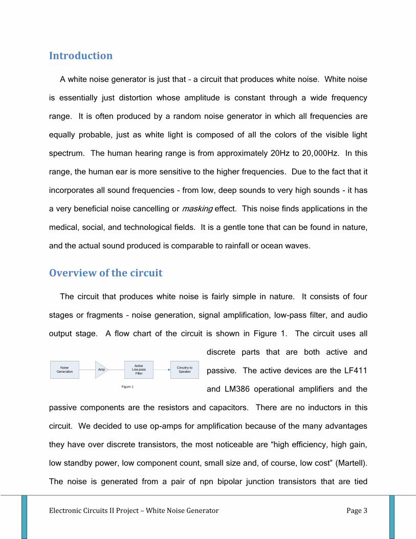
The circuit that produces white noise is fairly simple in nature. It consists of four
stages or fragments – noise generation, signal amplification, low-pass filter, and audio
output stage. A flow chart of the circuit is shown in Figure 1. The circuit uses all
discrete parts that are both active and
passive. The active devices are the LF411
and LM386 operational amplifiers and the
passive components are the resistors and capacitors. There are no inductors in this
circuit. We decided to use op-amps for amplification because of the many advantages
they have over discrete transistors, the most noticeable are “high efficiency, high gain,
low standby power, low component count, small size and, of course, low cost” (Martell).
The noise is generated from a pair of npn bipolar junction transistors that are tied
Noise
GenerationAmp
Active Low-pass
Filter
Circuitry to
Speaker
Figure 1

Electronic Circuits II Project – White Noise Generator Page 4
together at their base terminals. This basically creates a zener diode and it is biased in
the reverse breakdown region of operation. Being operated in this region, the pn
junction starts to exhibit the zener breakdown phenomenon, and as such produces shot
noise and creates a low-level, constant amplitude distortion signal. The noise
generation stage is ac coupled to the amplification stage so as to pass the distorted
signal but block the dc signal. The amplifier is set up in an inverting configuration which
uses a negative feedback loop. This negative feedback helps to stabilize the output
even further and helps to protect the signal from any spike that might occur. The gain of
this amplifier stage is Av=100, and is 180˚ out of phase, as shown in the next section.
The output of the amplification stage is then passed through a low-pass filter (LPF).
Since human hearing ranges from 20Hz to 20kHz, the filter is design to pass these first
20kHz and block the higher (useless) frequencies. The cutoff frequency was design to
be approximately 13kHz, with a -40dB/decade decrease thereafter. The passed signal
from the LPF then enters an audio output stage. This stage basically amplifies the
signal to a level that can be output through a speaker. The next section describes each
of the stages in more depth and shows the circuit schematic for each fragment.
Circuit Subsets
Noise Generation Stage
The first stage in our circuit is noise generation, where the constant power output
is produced. We decided to generate noise with the zener breakdown
phenomenon. Zener breakdown occurs when a zener diode is run in the reverse-
breakdown region of operation. This usually occurs when approximately -1mA of
current is passed through the diode. At this current level the zener diode enters

Electronic Circuits II Project – White Noise Generator Page 5
reverse breakdown and the current through it drops rapidly while the voltage
across it remains relatively constant. This
voltage level is termed zener voltage and
is represented by VZ. The I-V plot showing
this phenomenon is shown in Figure 2.
The noise generated while operating a
zener diode in this region is based on the
avalanche breakdown that occurs in the pn
junction. In our circuit we actually did not use a zener diode but instead two npn
bipolar transistors. These two transistors are tied together at their bases and
connected to the same power supply. One of the BJTs is connected to the power
supply at its collector terminal and tied to ground at the emitter. The other BJT is
connected to the power supply at its emitter terminal and the collector terminal is
floating. This essentially creates a pn junction all the same as
a zener diode. The next step in the generation process was to
make sure that we were operating the transistors (pn junction)
in the reverse breakdown region. This was accomplished by
applying a +15VDC supply as power. To protect the power
supply we put a 4.7k resistor in series with the transistors.
We also put a 1uF capacitor from +15V to ground as a
blocking cap. This basically makes up the noise generation
stage of the circuit. The circuit schematic of this stage is shown in Figure 3.
Figure 2
Q2
1uF
4.7k
0
Q1
0
Vs
up
ply
15V
Figure 3

Electronic Circuits II Project – White Noise Generator Page 6
Amplification of Noise Signal
The next step in white noise generation is to amplify the very low noise that is
produced by the transistors running in reverse breakdown. This was
accomplished by using an operational amplifier with negative feedback. We
decided to use a LF411 as the amplifier because of its extremely high open-loop
gain (~250,000) and high input impedance
(>106 Ω). Both of these are large enough to
consider infinite, therefore ideal op-amp
analysis was used. One of the major non-ideal
characteristic of this amplifier is that the output
of the circuit cannot go past the power supply
rails, plus-or-minus fifteen volts in our case.
This is okay though because the noise
generated and output is orders of magnitude
smaller than 15V, and therefore we ignored this
shortcoming. Using negative feedback we were able to control the gain of the
411 externally. We wanted a gain of approximately 100 so we used a 1kΩ
resistor at the inverting terminal of the op-amp and used a 100kΩ resistor from
the output (pin 6 for the LM411) back to the inverting terminal. In doing so we
created an inverting amplifier with the gain of:
AV = –R2/R1 = -100k/1k = 100
The non-inverting terminal of the op-amp was grounded through a 1kΩ. The
circuit schematic of this stage is shown in Figure 4.
1uF
100k
1k
0
15V
1k
15V
U1
LF411
3
2
74
6
1
5+
-
V+
V-
OUT
B1
B2
0
0
Figure 4

Electronic Circuits II Project – White Noise Generator Page 7
Active Low-Pass Filter
Once the low-level noise is amplified it needs to be tailored to output over the
frequencies of interest, 0Hz to 20kHz in our case (human hearing range). To
accomplish this we designed an active low pass filter with a cutoff frequency of
13kHz. It is termed “active” because it uses an op-amp instead of just passive
components such as resistors, capacitors, and inductors. The circuitry of this
LPF is shown in Figure 5. The op-amp we used to
implement this filter was again an LF411. This
time however it had both positive and negative
feedback, allowing us to customize the output
characteristics. The first decision we had to make
was whether or not to have gain with this amplifier.
Since we had a dedicated stage just for
amplification of the noise, we decided to set it up
as a voltage follower, giving us unity gain over the
frequency range of interest. It also provides high
input impedance and very low output impedance.
At low frequencies (<<13kHz) the filter passes the noise generated by the
transistors. At frequencies above 13kHz the filter exhibits a two-pole roll-off,
falling approximately 40dB/decade. This is desirable because humans cannot
hear frequencies above 20kHz. The transfer function of the active low-pass filter
includes a Q term which describes the peak response and bandwidth. For a Q
larger than 0.71, the filter exhibits a peaked response that is usually undesirable,
15V0
0
R10
1k
62k
200pF
62k
0
200pF
R9
1k
0
U2
LF411
3
2
74
6
1
5+
-
V+
V-
OUT
B1
B2
15V
Figure 5

Electronic Circuits II Project – White Noise Generator Page 8
whereas a Q below 0.71 does not take maximum advantage of the filter’s
bandwidth capability. This is a direct implication of the gain-bandwidth product.
Increasing bandwidth comes at the cost of gain, and vice-versa. We chose to
design for a Q equal to 0.71 to maximize bandwidth without a peak response. As
mentioned earlier, active low-pass filters use positive and negative feedback.
“The filter uses positive feedback through [the capacitor from the output of the
411 to the non-inverting terminal] at frequencies above dc to realize complex
poles without the need for inductors” (Jaeger and Blalock 571). Negative
feedback comes from the output, through the voltage divider, and back to the
inverting terminal. The 56k resistor and the 100k resistor set the Q-point of the
filter, and since there is a path to ground the op-amp’s gain is not affected
(voltage follower).
Audio Output Stage
The last stage of the circuit is an audio amplifier. We chose to use an LM386-1,
which has an output power level of 300mW. These are widely available op-amps
and can be operated as low as five volts. One unique aspect of these audio
amps is the gain can be modified by connecting a resistor and capacitor from pin
one to pin six. As with the LF411, increasing gain comes with lower output power
and should only be used when the input level is extremely low. The non-inverting
terminal is connected to a 10k potentiometer, which is itself connected to the
output of the LPF stage and ground, and becomes the input to the amplifier. The
potentiometer controls the gain of the LM386 externally. The inverting terminal is
then connected to ground. The power supplied to the op-am is +15V and 0V, and
as before to protect the proto-boards internal power supply, we put a 10Ω resistor
Electronic Circuits II Project – White Noise Generator Page 9
in series and a 220μF electrolytic capacitor to ground. This becomes a blocking
capacitor and is discussed in the first paragraph of this section. The output of this
amp goes through a 220μF coupling capacitor and on to the speaker to output the
desired white noise. The speaker itself is a two-wire device in which one input
comes from the LM386 and the other is tied to ground.
Analysis
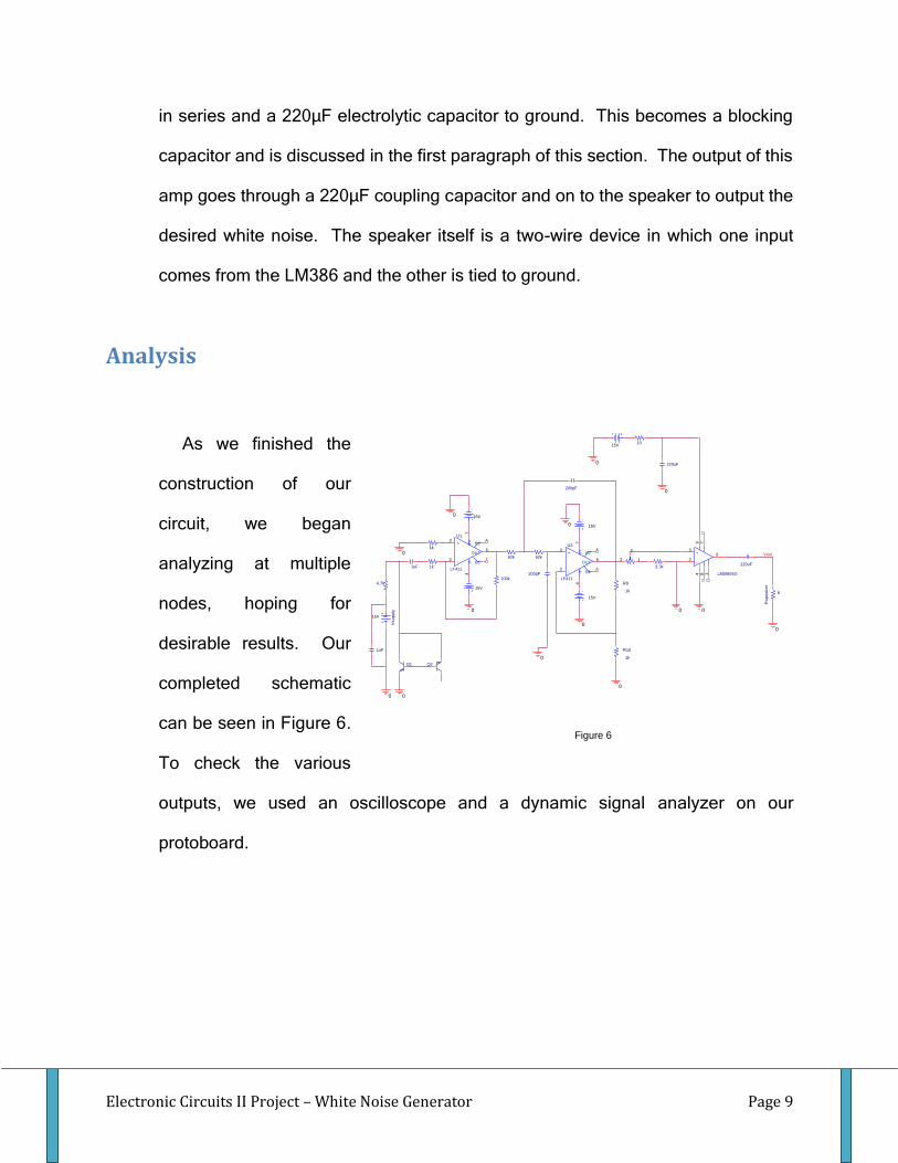
As we finished the
construction of our
circuit, we began
analyzing at multiple
nodes, hoping for
desirable results. Our
completed schematic
can be seen in Figure 6.
To check the various
outputs, we used an oscilloscope and a dynamic signal analyzer on our
protoboard.
Q2
1uF
3.3k
15V
4.7k
0
1uF
Rspeaker
8
0
Vout
10
0
0
0
15V
Q1
1k
0
R10
1k
62k
220uF
0
200pF
0
0
220uF
62k
0
+
-
LM386/SO
3
25
6
14 87
0
15V
200pF
R9
1k
0
1k
Vsupply
15V
3 1
2
U1
LF411
3
2
74
6
1
5+
-
V+
V-
OUT
B1
B2
15V
0
100k
U2
LF411
3
2
74
6
1
5+
-
V+
V-
OUT
B1
B2
15V
0
Figure 6

Electronic Circuits II Project – White Noise Generator Page 10
We checked the output at the final
stage of the circuit, as shown in
Figure 7. This plot shows a relatively
constant noise being output in our
desired range of frequencies (from
0Hz to around 20kHz; audible range).
Roll-off due to the LPF stage is also
visible at the 13kHz we designed for
in this screenshot. Unfortunately, we
were unable to hear any white noise output from the speakers. We concluded
that this was due to a lack of
amplification of the noise signal in the
amp stage of our circuit. Moving
backward a node we then took an
oscilloscope screenshot and dynamic
signal analyzer plot of the output of the
active low-pass filter stage is shown in
Figure 8. At this node we were able to
successfully generate white noise and in
Figure 8a you can visibly see the low-
pass filter roll-off we hoped for.
Unfortunately the frequency range of
constant power was significantly lower
Figure 7
Figure 8 (a) Dynamic Signal Analyzer (top) and (b)
Oscilloscope (bottom)

Electronic Circuits II Project – White Noise Generator Page 11
than expected. The corner frequency is approximately 5kHz, which is 8kHz less
than we designed for. Comparing Figure 7 and Figure 8a it is shown that the
output level of the LPF stage is much larger in amplitude than the output of the
audio stage. For some reason (probably the LM386 itself) there was significant
signal attenuation in going through the last stage, and this attenuation dropped
the output level too low to be picked up by the speaker. The output amplitude
level of the LPF stage was approximately 0.05mV, more than enough to power
the speaker and output noise.
Discussion
We ran into a couple of problems
during our analysis of our physical
circuit - including lack of amplification
and signal attenuation which dropped
our signal. A solution to the problem
of no sound output out of the final
stage is to add a second amplification
stage to the circuit. Because
amplification is dependent on resister
value ratios of the negative feedback
loop, they must be adjusted to create a larger ratio; thus a larger amplification.
Installing a higher sensitivity speaker to pick up the very low output signal is also
an option.
Figure 9
Electronic Circuits II Project – White Noise Generator Page 12
Looking back on our design we realized that we were possibly “over gaining”
our amplification stage and thereby affectively decreasing our potential
bandwidth. The early roll-off could also be due to the amp stage LM411’s
internal capacitance. It was earlier stated that as you increase gain you lose
bandwidth, and vice-versa. We designed for a gain of 100, and in return lost
most of our desired bandwidth. This can be seen in Figure 9, which is a dynamic
signal analysis of the output of the amplification stage.
Conclusion
In the end we were able to successfully compensate and make adjustments
to generate white noise. We ended up having to scrap our audio output stage
and directly connect the speaker to the output of the active low-pass filter. This
was a fairly easy to build circuit due to the basic component and was a definite
learning experience.

Electronic Circuits II Project – White Noise Generator Page 13
Works Cited
"Building a Low-Cost White-Noise Generator." Maxim. 14 Mar. 2005. 05 Apr. 2008
<http://www.maxim-ic.com/appnotes.cfm/appnote_number/3469>.
"Capacitors Blocking DC." All About Circuits. Feb. 2006. 15 Apr. 2008.
"Capacitor Types and Colors." Elecraft. 20 Apr. 2008
<http://www.elecraft.com/Apps/caps.htm>.
“Colors of noise.” Wikipedia, The Free Encyclopedia. 4 May 2008, 22:40 UTC. Wikimedia
Foundation, Inc. 7 May 2008 < http://en.wikipedia.org/wiki/Colors_of_noise>.
Costello, Carol. "The Basics of Making a Presentation." Electrical Engineering Dept. University of Texas
At San Antonio, San Antonio. Apr. 2008.
Hansen, Lars. Electrical Engineer Lab 1. University of Texas At San Antonio, San
Antonio. Spring 2008.
Horowitz, Paul, and Hill Winfield. The Art of Electronics. New York: Cambridge UP, 1989.
Introduction to Op Amps. Dept. of EE., Swathmore University. 03 May 2008
<http://www.swarthmore.edu/NatSci/echeeve1/Class/e72/E72L2/Lab2(OpAmp).html>.
Martel, Mike. "Integrated Circuit Audio Amplifiers." 04 May 2008
<httl://www.rason.org/Projects/icamps/icamps.htm>.
Ortiz, John. Electronic Circuit II. University of Texas At San Antonio, San Antonio.
Summer 2008.
Sound Masking Systems. Avlelec. 20 Apr. 2008
<http://www.avlelec.com/PDFs/soundmasking_whitepaper.pdf>.
"Tiny White Noise Generator." Web-Ee. 15 Apr. 2008 <http://web-
ee.com/schematics/noise_generation/pseudo-random-white-noise/>.
Electronic Circuits II Project – White Noise Generator Page 14
"White Noise Generator." Waynesrngcomp. 5 Apr. 2008
<http://world.std.com/~reinhold/waynesrngcomp.gif>.
"Wide-Band Analog White-Noise Generator." Electronic Design. 3 Nov. 1997. 20 Apr. 2008
<http://electronicdesign.com/Articles/Index.cfm?AD=1&ArticleID=6356>.
Wisniewski, Joseph S. "The Colors of Noise." Product Technology Partners. 07 Oct. 1996. Ford
Motor Company. 18 Apr. 2008 <http://www.ptpart.co.uk/show.php?contentid=71>.


