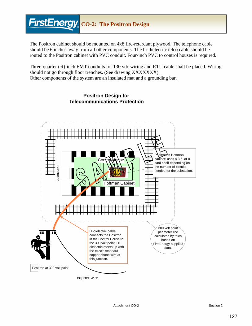
MANUAL This document will be published as a read-only PDF document. It is the responsibility of each external or internal user to ensure they are using the latest revision of this document. To access the latest version of this manual, please visit www.firstenergycorp.com/feconnect and click on “Wholesale Generation Interconnection Manual”. Rev. 1 Effective Date: August 6, 2010
Manual Overview Purpose This manual contains the Transmission Owner (TO) requirements for wholesale generation interconnection projects consistent with the interconnection process as defined in the PJM Open Access Transmission Tariff (OATT) and applicable PJM Manuals. The purpose of this document is to provide a detailed list of FirstEnergy (FE) requirements, including required documentation for operational and property transfer, if applicable, when a generation interconnection is requested by an Interconnection Customer (IC). These requirements will facilitate the safe, efficient and reliable integration of the Interconnection Facilities into the transmission system. Using this Manual Explaining concepts is as important as presenting technical requirements to the wholesale generation IC. This approach is reflected in the way the material is organized and presented in this manual. This Introduction presents an overview of how to use the various documents referenced throughout the manual.
What You Will Find In This Manual • Introduction: This section explains key terms and concepts. It provides an overview of
how the different documents are integrated and clarifies the primary requirement that all deliverables associated with a specific milestone must be met before moving to the next project milestone.
• Project Requirements: This section describes specific requirements, guidelines, or procedures that the TO will transmit and the IC must provide as described by milestones during the project.
• Exhibits and Attachments: This section contains documents, forms, and tables that are referenced throughout this manual.
• Glossary of Terms: This section provides definitions of the terms and acronyms used throughout the manual.
Process Overview The IC is required to review the entire FirstEnergy Wholesale Generation Interconnection Customer Requirements manual and develop a construction schedule for the project. The construction schedule must contain specific milestones, and the required documents associated with each milestone must be completed and submitted by the IC prior to moving to the next project milestone. Each required document will then be reviewed and accepted by the TO before the project can move to the next project milestone. Disclaimer In this document, the Transmission Owner (TO) has attempted to consolidate all requirements for safe, efficient and reliable interconnection of the Generator Unit and Interconnection Facilities to the transmission system. This manual may not be exhaustive of all PJM OATT and applicable PJM Manuals (PJM Documents) and is only intended to serve as an aid to interconnection. Further the PJM OATT and PJM Manuals may change from time to time. The TO retains the right to update this manual as necessary. In the event there are any conflicts and/or inconsistencies between this manual and the PJM OATT and PJM Manuals, the PJM documents shall govern. It is the Interconnection Customer’s responsibility to ensure that all interconnection requirements under the PJM OATT and PJM manuals are met. Manual Overview
Key Documents The following four documents are used throughout the project process:
1. Wholesale Generation Interconnection Customer Requirements Document (“Requirements Document”) - A detailed narrative document that includes all aspects of the requirements that the IC must provide for a Wholesale Generation Interconnection Project. Refer to Section 1 for the Customer Requirements and Section 2 for related Attachments.
2. Wholesale Generation Interconnection Customer Documentation Checklist (“Documentation Checklist”) - Each Requirements Document has an associated Documentation Checklist. The Documentation Checklist summarizes the requirements described in the Requirements Document. Each requirement on the checklist has a specific timing requirement for when it must be provided. Timing requirements are referred to as milestone events. Refer to Section 3 for the Customer Documentation Checklist.
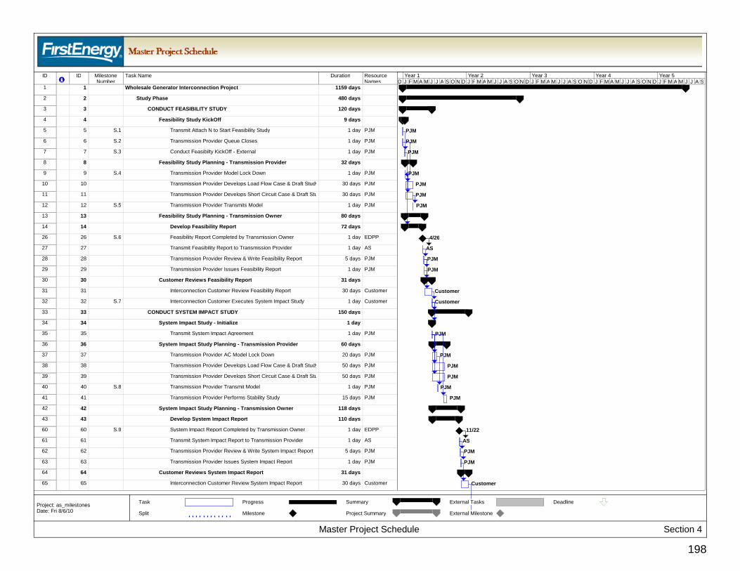
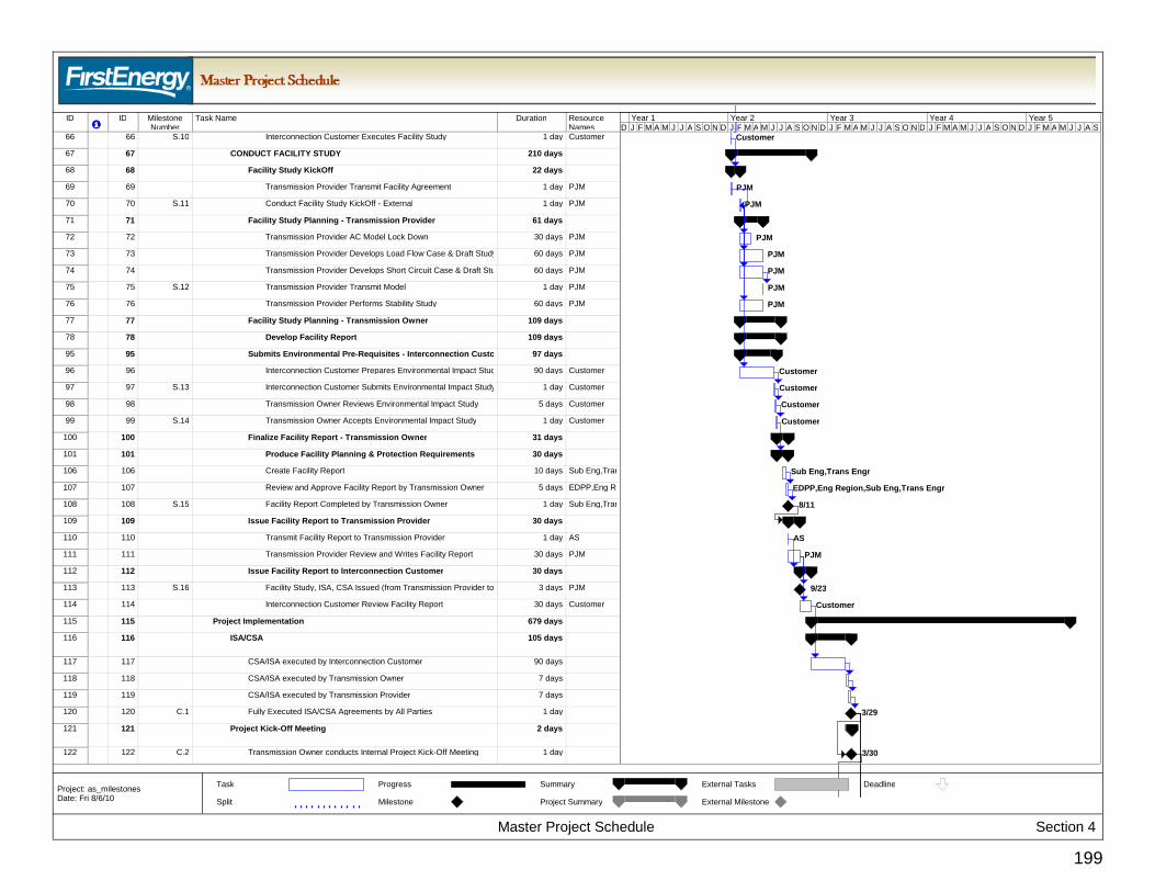
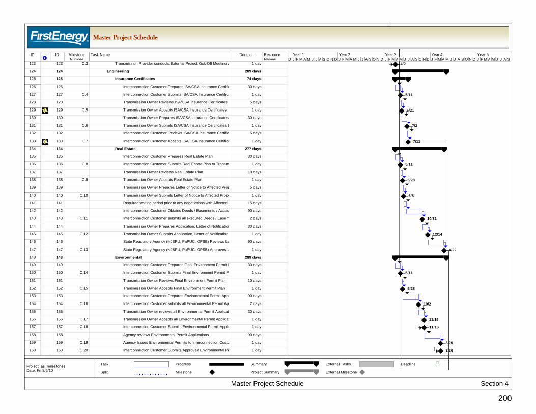
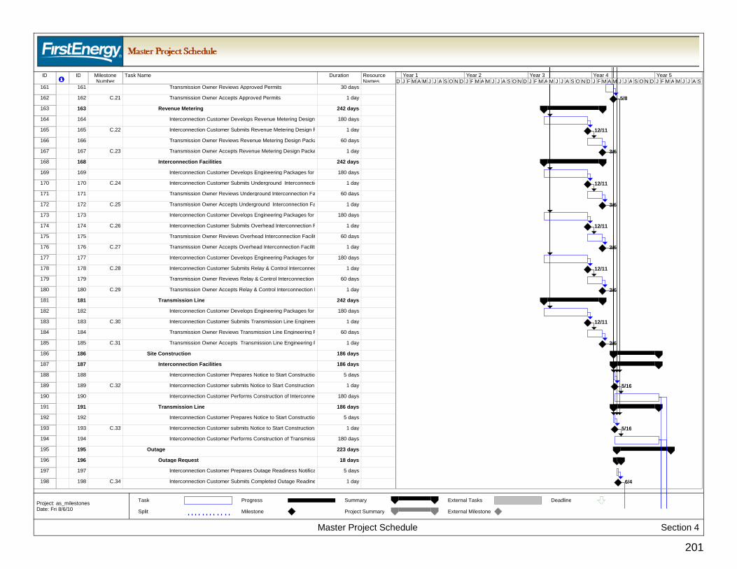
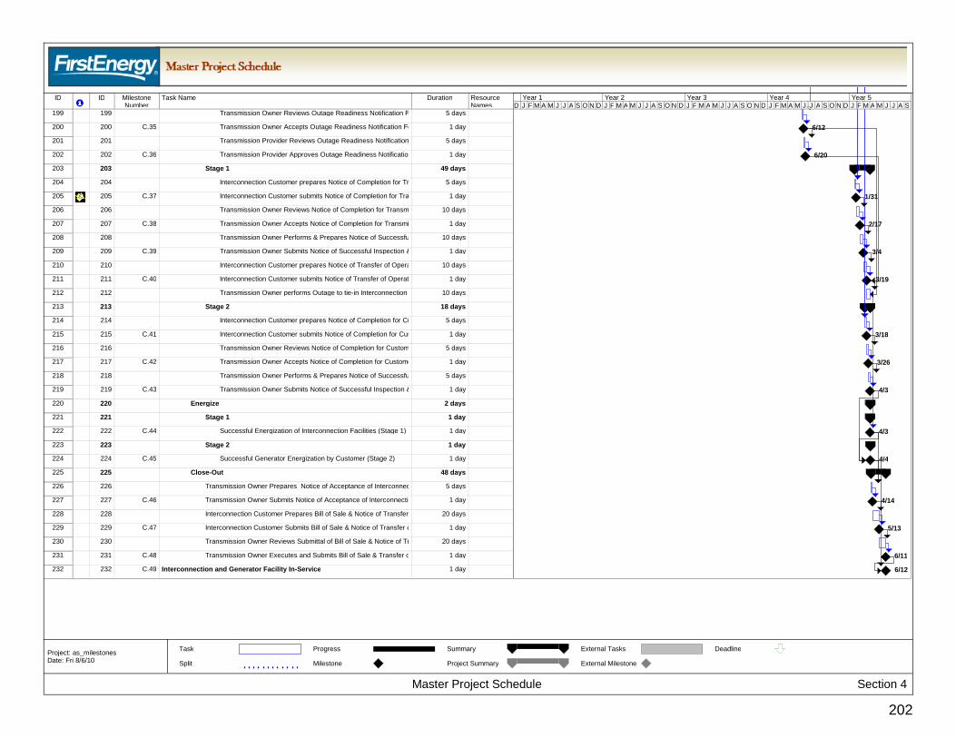
3. Master Project Schedule - The Master Project Schedule includes all of the primary tasks and the time frame in which they must be completed. A milestone is an event within the Master Project Schedule that includes the timing for when the event must occur. Each milestone represents one of two types of activities; 1) start of a new event, or 2) completion of a major deliverable. Refer to Section 4 for the Master Project Schedule.
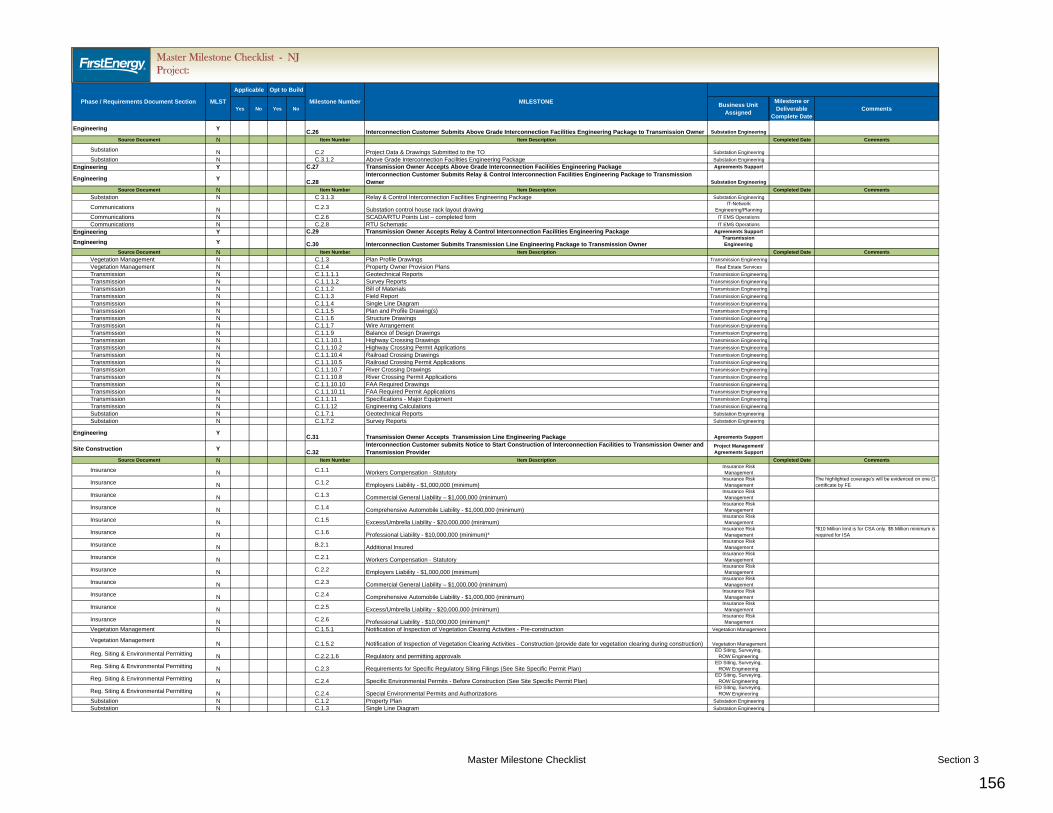
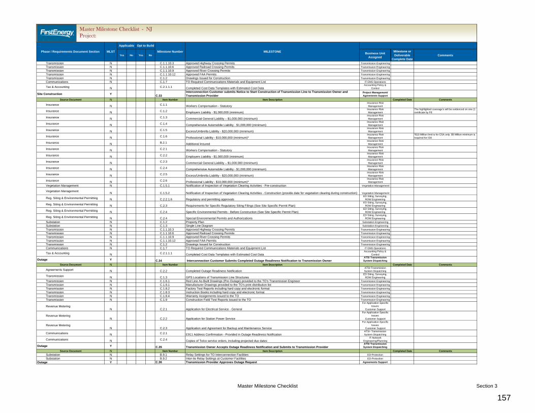
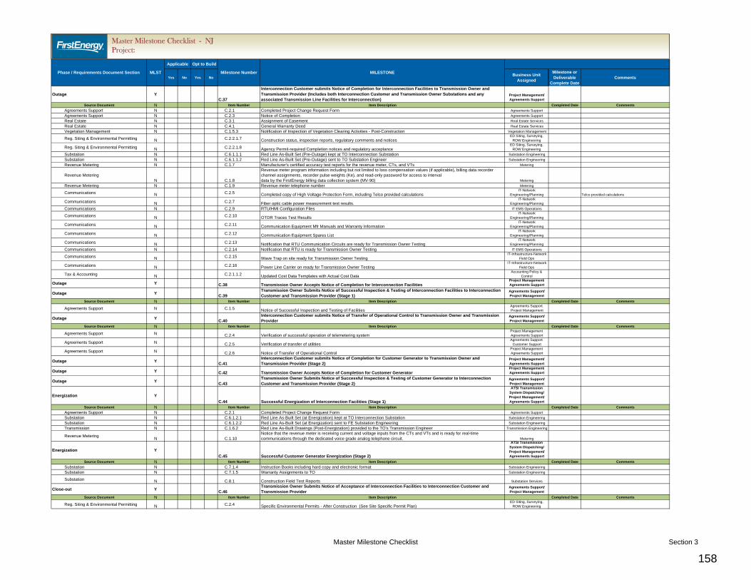
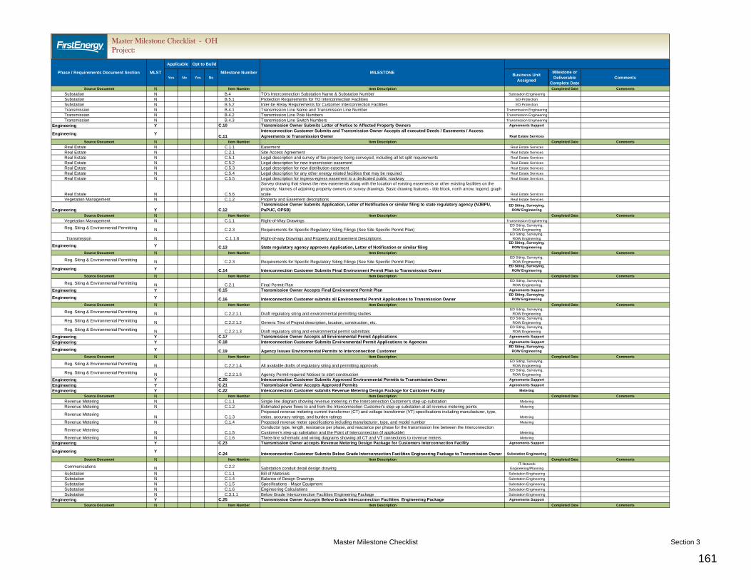
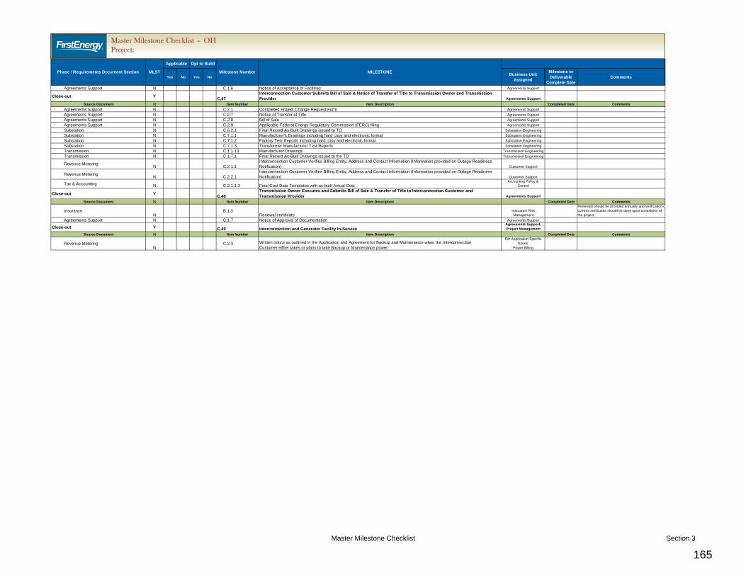
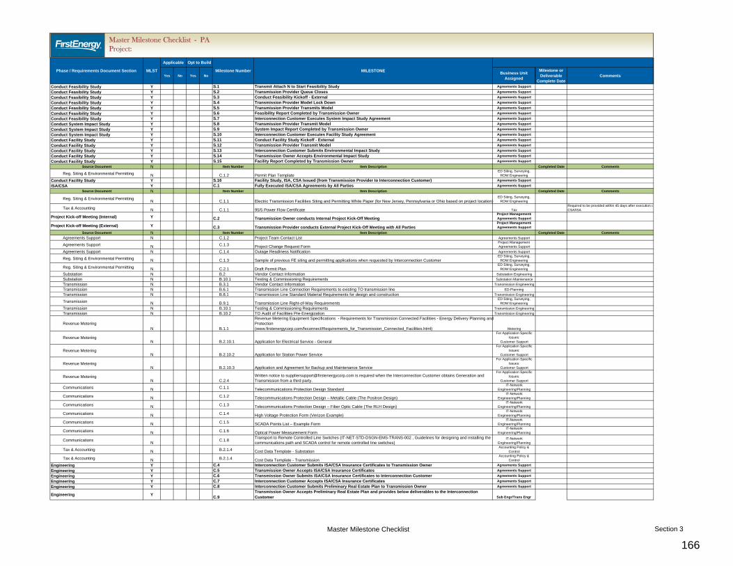
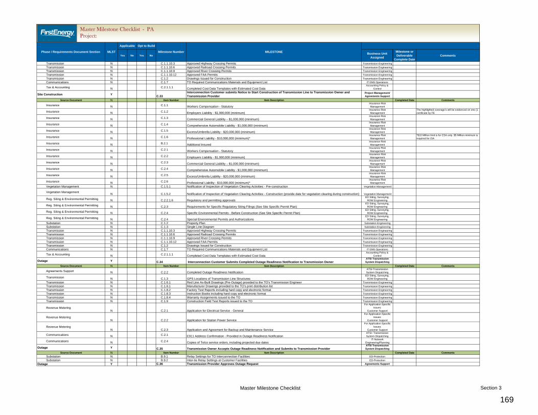
4. Master Milestone Checklist - This checklist integrates the requirements from each Documentation Checklist and aligns respective milestones into one master list. This list is used to record the action for specific required deliverables. All requirements for the milestone must be completed before moving to the next project milestone. Refer to Section 3 for the Master Milestone Checklist. Note, this is the first checklist in Section 3.
Key Terms Interconnection Customer (IC) - A Generation Interconnection Customer and/or a Transmission Interconnection Customer. Transmission Provider (TP) - PJM / Regional Transmission Organization. PJM – Transmission Provider (TP) Transmission Owner (TO) - Each entity that owns, leases or otherwise has a possessory interest in facilities used for the transmission of electric energy in interstate commerce under the PJM OATT. FirstEnergy (FE) – Transmission Owner (TO) (or affiliates, e.g,, Ohio Edison Company, The Cleveland Electric Illuminating Company, The Toledo Edison Company, Pennsylvania Power Company, Pennsylvania Electric Company, Metropolitan Edison Company, and Jersey Central Power & Light Company)
• For additional terms and definitions, see Appendix 1, Definitions, in the PJM Construction Service Agreement (CSA) and/or the Interconnection Service Agreement (ISA). In addition, all capitalized terms herein shall have the meaning set forth in Appendix 1 of the CSA/ISA.
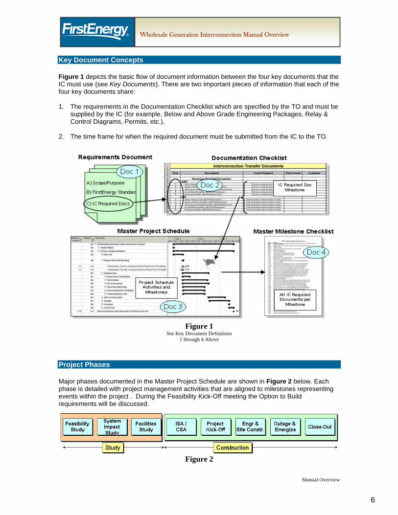
Key Document Concepts Figure 1 depicts the basic flow of document information between the four key documents that the IC must use (see Key Documents). There are two important pieces of information that each of the four key documents share: 1. The requirements in the Documentation Checklist which are specified by the TO and must be
supplied by the IC (for example, Below and Above Grade Engineering Packages, Relay & Control Diagrams, Permits, etc.).
2. The time frame for when the required document must be submitted from the IC to the TO.
Figure 1
See Key Document Definitions 1 through 4 Above
Project Phases Major phases documented in the Master Project Schedule are shown in Figure 2 below. Each phase is detailed with project management activities that are aligned to milestones representing events within the project . During the Feasibility Kick-Off meeting the Option to Build requirements will be discussed.
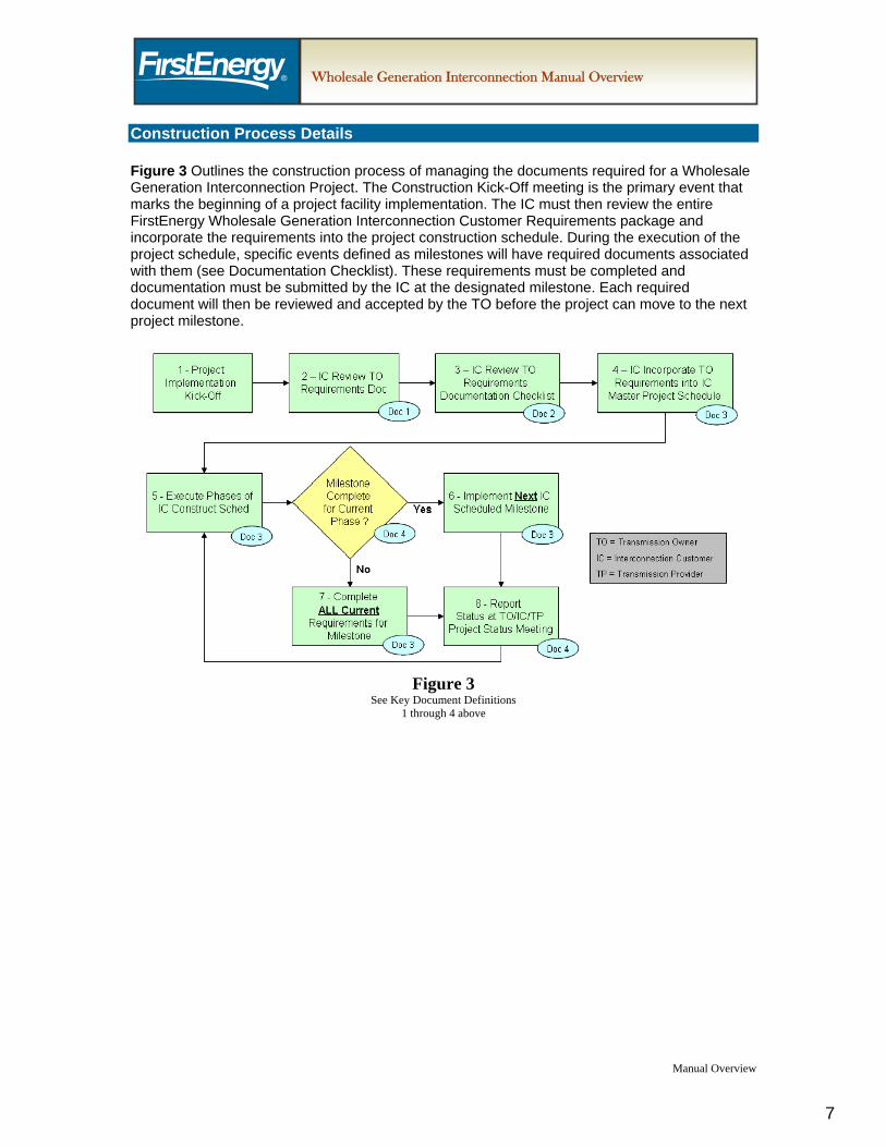
Construction Process Details Figure 3 Outlines the construction process of managing the documents required for a Wholesale Generation Interconnection Project. The Construction Kick-Off meeting is the primary event that marks the beginning of a project facility implementation. The IC must then review the entire FirstEnergy Wholesale Generation Interconnection Customer Requirements package and incorporate the requirements into the project construction schedule. During the execution of the project schedule, specific events defined as milestones will have required documents associated with them (see Documentation Checklist). These requirements must be completed and documentation must be submitted by the IC at the designated milestone. Each required document will then be reviewed and accepted by the TO before the project can move to the next project milestone.
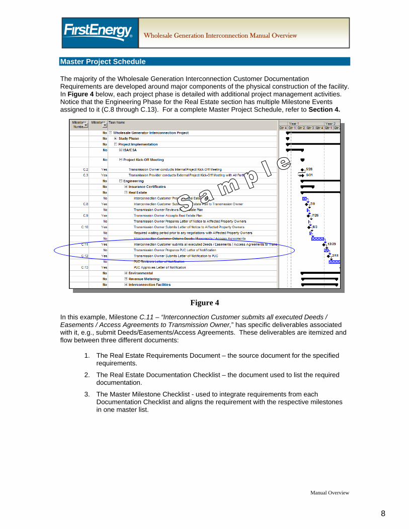
Master Project Schedule The majority of the Wholesale Generation Interconnection Customer Documentation Requirements are developed around major components of the physical construction of the facility. In Figure 4 below, each project phase is detailed with additional project management activities. Notice that the Engineering Phase for the Real Estate section has multiple Milestone Events assigned to it (C.8 through C.13). For a complete Master Project Schedule, refer to Section 4.
Manual Overview
Figure 4
In this example, Milestone C.11 – “Interconnection Customer submits all executed Deeds / Easements / Access Agreements to Transmission Owner,” has specific deliverables associated with it, e.g., submit Deeds/Easements/Access Agreements. These deliverables are itemized and flow between three different documents:
1. The Real Estate Requirements Document – the source document for the specified requirements.
2. The Real Estate Documentation Checklist – the document used to list the required documentation.
3. The Master Milestone Checklist - used to integrate requirements from each Documentation Checklist and aligns the requirement with the respective milestones in one master list.
The ten major areas that have a Requirements Document and Documentations Checklist associated with them are:
1. Agreements Support
2. Real Estate
3. Vegetation Management
4. Insurance
5. Regulatory Siting and Environmental Permitting
6. Substation
7. Transmission Line
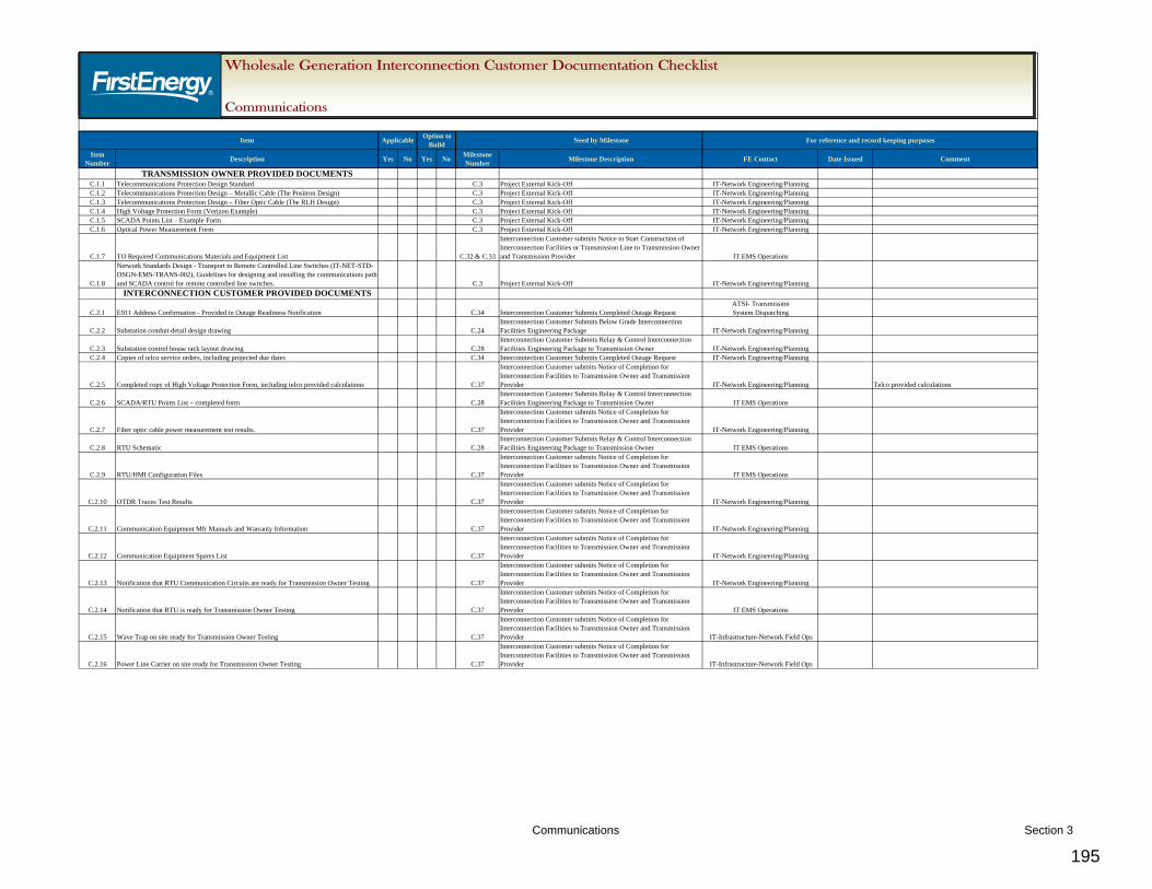
8. Communications
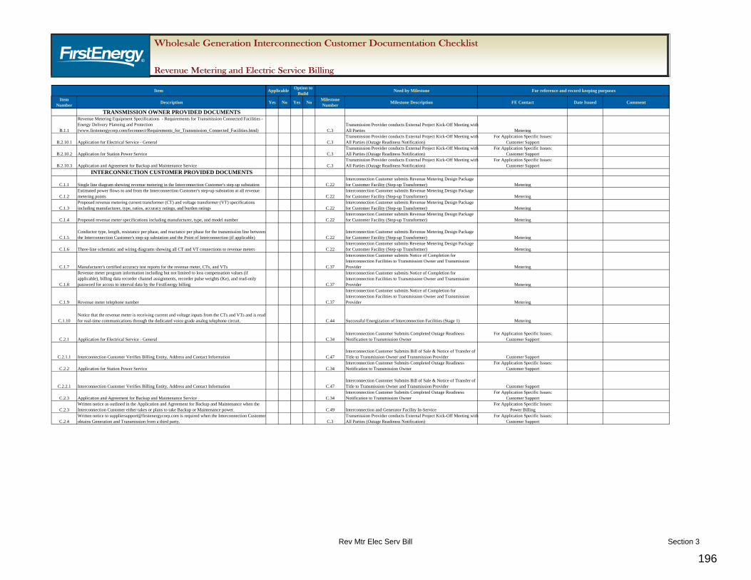
9. Revenue Metering & Electric Service Billing
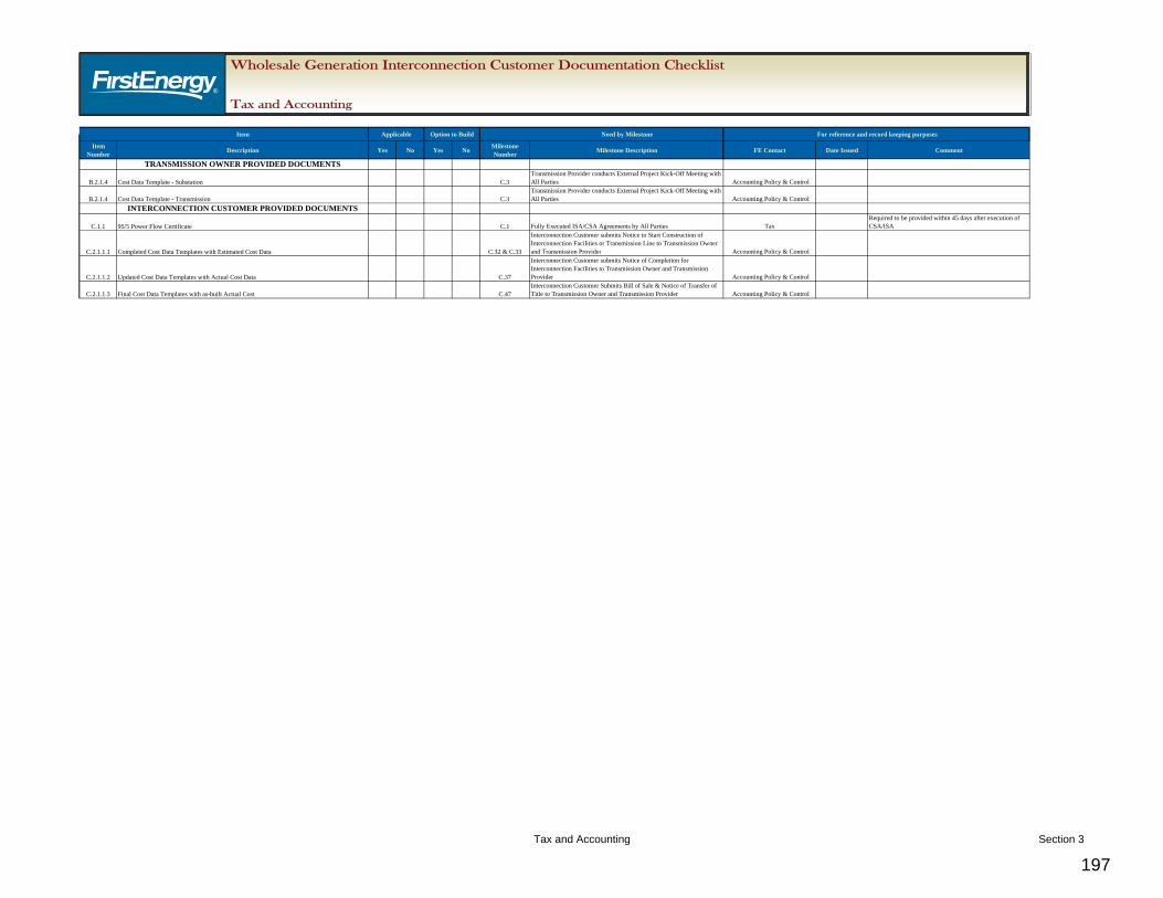
10. Tax & Accounting
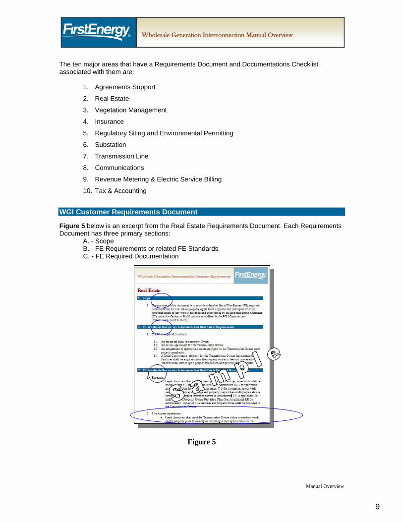
WGI Customer Requirements Document Figure 5 below is an excerpt from the Real Estate Requirements Document. Each Requirements Document has three primary sections:
A. - Scope B. - FE Requirements or related FE Standards C. - FE Required Documentation
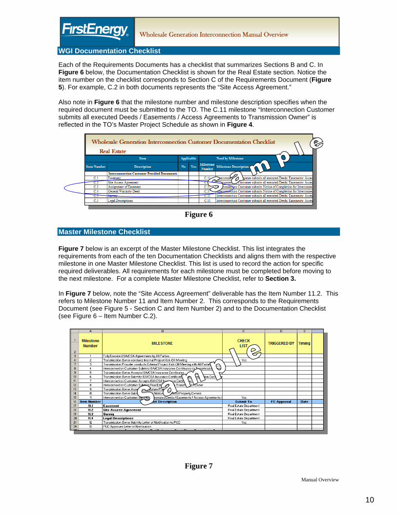
WGI Documentation Checklist Each of the Requirements Documents has a checklist that summarizes Sections B and C. In Figure 6 below, the Documentation Checklist is shown for the Real Estate section. Notice the item number on the checklist corresponds to Section C of the Requirements Document (Figure 5). For example, C.2 in both documents represents the “Site Access Agreement.” Also note in Figure 6 that the milestone number and milestone description specifies when the required document must be submitted to the TO. The C.11 milestone “Interconnection Customer submits all executed Deeds / Easements / Access Agreements to Transmission Owner” is reflected in the TO’s Master Project Schedule as shown in Figure 4.
Manual Overview
Figure 6
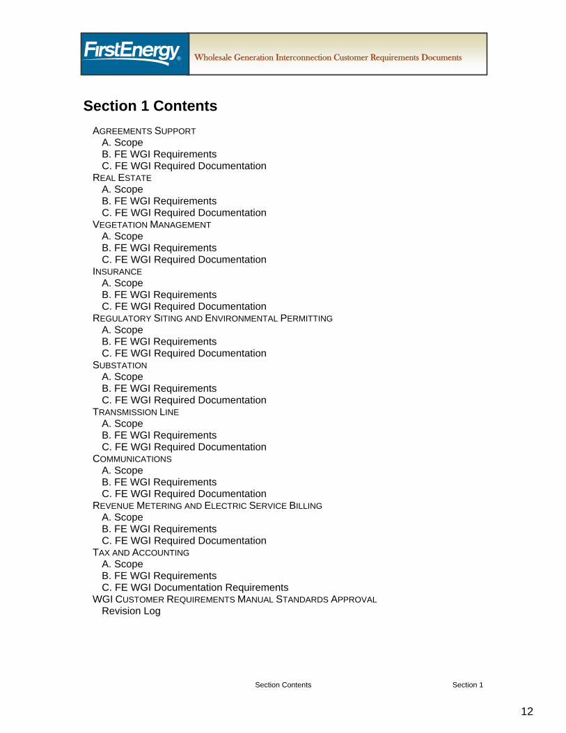
Master Milestone Checklist Figure 7 below is an excerpt of the Master Milestone Checklist. This list integrates the requirements from each of the ten Documentation Checklists and aligns them with the respective milestone in one Master Milestone Checklist. This list is used to record the action for specific required deliverables. All requirements for each milestone must be completed before moving to the next milestone. For a complete Master Milestone Checklist, refer to Section 3. In Figure 7 below, note the “Site Access Agreement” deliverable has the Item Number 11.2. This refers to Milestone Number 11 and Item Number 2. This corresponds to the Requirements Document (see Figure 5 - Section C and Item Number 2) and to the Documentation Checklist (see Figure 6 – Item Number C.2).
Schedule Conclusion The Master Project Schedule is used to convey to the IC the required deliverables throughout the major project phases. It is not intended to be a detailed implementation schedule for construction activities. It is required that the milestones used in the Master Project Schedule are integrated into the overall engineering and construction project schedule to ensure efficiency and standardization of information reported throughout the project. By adhering to the process prescribed in the enclosed documentation, all parties will be able to ensure a safe, efficient and reliable integration with the successful transfer of the Interconnection Facilities into the transmission system.
1. This document contains the Transmission Owner (TO) requirements for wholesale generation
interconnection projects consistent with the interconnection process as defined in the PJM Open Access Transmission Tariff (OATT) and applicable PJM manuals. The purpose of this document and attached checklist is to provide a detailed list of FirstEnergy (FE) requirements, including required documentation for operational and property transfer, if applicable, when a generation interconnection is requested by an Interconnection Customer (IC). These requirements will facilitate the safe, efficient and reliable integration of the Interconnection Facilities into the transmission system.
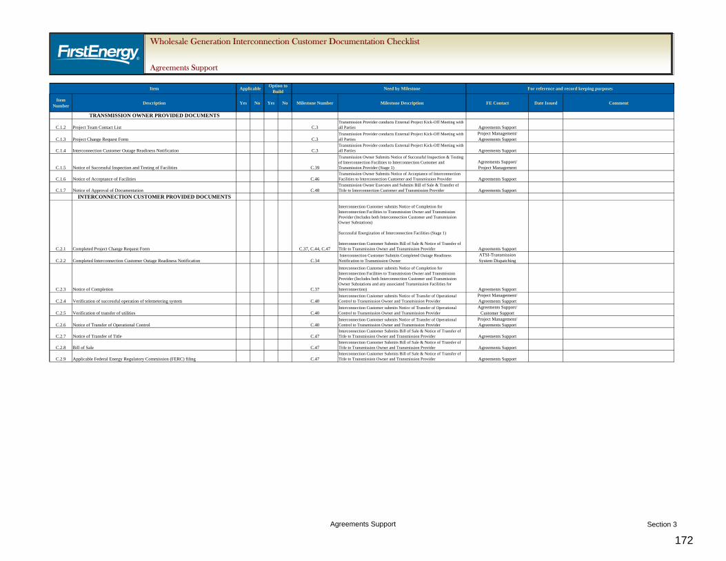
2. The “Wholesale Generation Interconnection Customer Agreements Support Documentation Checklist” will be used to track the status of each document.
B. FE WGI Requirements
1. An IC requesting interconnection of a generating facility (including increases to the capacity
of an existing generating unit or decommissioning of a generating unit) within the PJM RTO must do so within PJM’s defined interconnection process which can be found at the PJM web site at: http://www.pjm.com/home.aspx. The PJM Operating Agreement, Schedule 6, and the PJM OATT, Part IV, describe the procedures used to process requests for interconnection with the PJM transmission system. Specific requirements for the interconnection request process, financial obligations, and milestone responsibilities can also be found in PJM Manual M14A. PJM Manual M14C describes the various studies and agreements required to complete the transmission interconnection planning process.
2. In addition to the Transmission Provider (TP) requirements, the IC should refer to the FE “Requirements for Transmission Connected Facilities” located at: http://www.firstenergycorp.com/feconnect/Requirements_for_Transmission_Connected_Facilities.html and the “FirstEnergy Wholesale Generation Interconnection Customer Requirements” for specific Real Estate, Vegetation Management, Insurance, Regulatory Siting and Environmental Permitting, Substation, Transmission Line, Communications, Revenue Metering and Electric Service Billing, and Tax and Accounting Requirements.
3. The IC must submit a completed Interconnection Request to the TP, execute the Feasibility Study Agreement (Attachment N in PJM OATT), and provide the required deposit and other specific documents as required by the PJM OATT, in order to reserve a place in PJM’s interconnection queue.
4. The IC will participate in a kickoff meeting with the TP and the TO within 45 days after receipt of a valid Interconnection Request, if the Interconnection Request is received in the first calendar month of the current New Services Queue; or within 30 days if the Interconnection Request is received within the second calendar month of the current New Services Queue; or in 20 days if the Interconnection Request is received in the third calendar month of the date of the beginning of the New Services Queue.
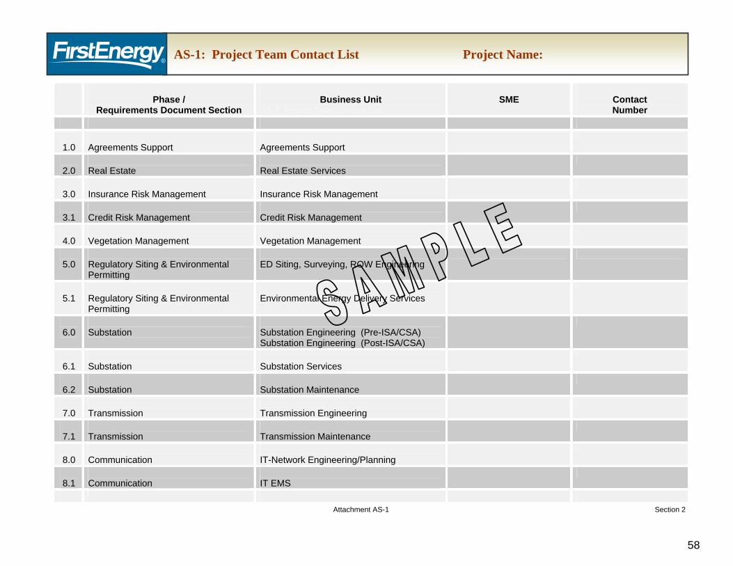
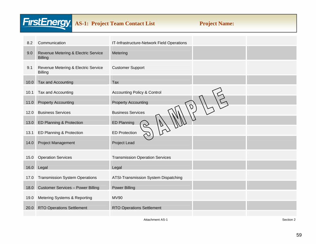
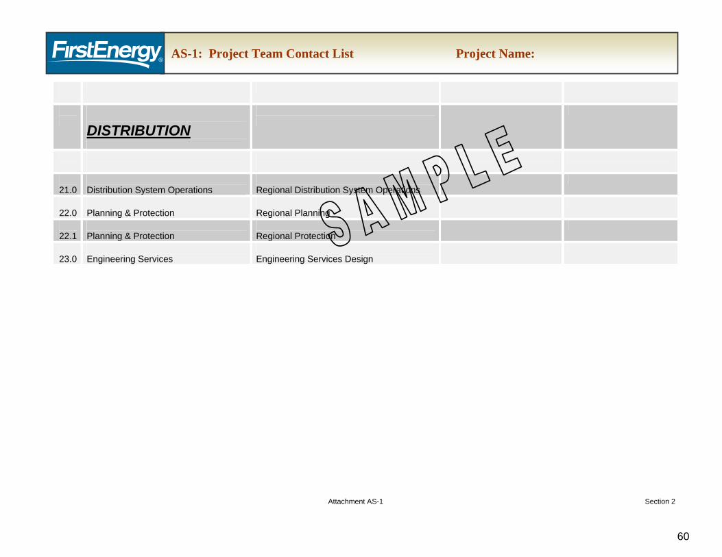
5. The TO will provide a Project Team Contact List (Attachment AS-1) for use by the TP and the IC. The Project Team Contact List will identify each of the TO primary contacts and will be used to assign responsibility for the Master Milestone Checklist.
6. The TP and the TO will coordinate efforts to complete the Feasibility Study Report for submittal to the IC within 90 days from the close of the New Services Queue. Upon submittal of the Feasibility Study Report to the IC, a System Impact Study Agreement will also be issued to the IC for execution.
7. The IC must return the executed System Impact Study Agreement to the TP within 30 days, along with the required deposit and other specific documents as required by the PJM OATT.
8. The TP and the TO will coordinate efforts to complete the System Impact Study Report for submittal to the IC. Due diligence shall be used to complete the System Impact Study within 120 days of the date the study commences. Upon submittal of the System Impact Study Report to the IC, a Facilities Study Agreement will also be issued to the IC for execution.
9. The IC must return the executed Facilities Study Agreement to the TP within 30 days, along with the required deposit and other specific documents as required by the PJM OATT.
10. The IC will participate in a Facilities Study kickoff meeting with the TP and the TO as scheduled by the TP.
11. The TP and the TO will coordinate efforts to complete the Facilities Study Report for submittal to the IC within the time estimated in the Facilities Study Agreement. Upon submittal of the Facilities Study Report to the IC, an Interconnection Service Agreement (ISA) also wi be issued to the IC for review and execution. The IC must return an executed copy of the ISA to the TP within sixty (60) days after receipt of the Facilities Study Report and ISA, along with the required security. The Interconnection Customer must also demonstrate that it has met the milestones specified in Section 212.5 of the PJM OATT. Within 45 days after receipt of the executed ISA, the TP will submit the Construction Service Agreement (CSA) to the IC for review and execution. The IC must return an executed copy of the CSA to the TP within ninety (90) calendar days of receipt of the CSA.
12. Within fifteen (15) days following full execution of the CSA/ISA, the IC shall participate in a project kickoff meeting with the TP and the TO. Note: The IC should refer to PJM Manual 14C for specific information related to the engineering and construction phase of the project.
13. The IC shall participate in (at a minimum) monthly project meetings with the TP and the TO where they will provide and update their design and construction schedules, their major equipment orders and delivery schedules, and key milestones.
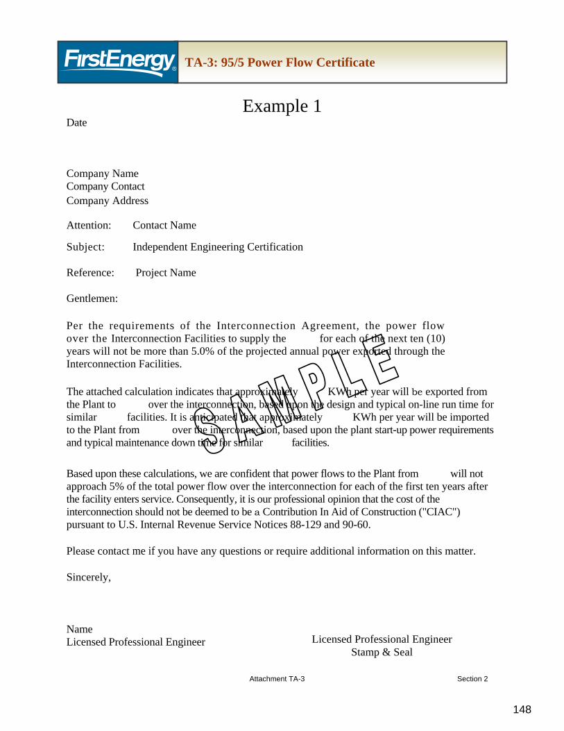
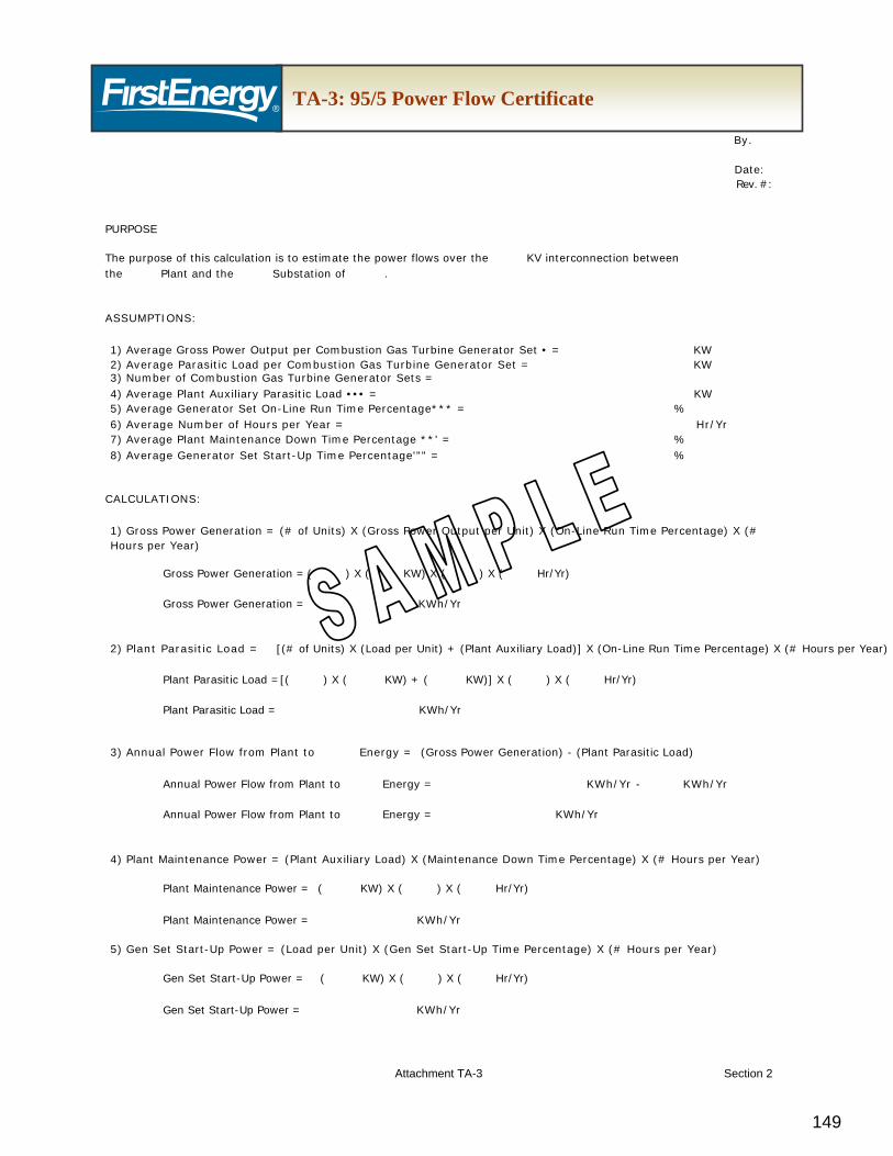
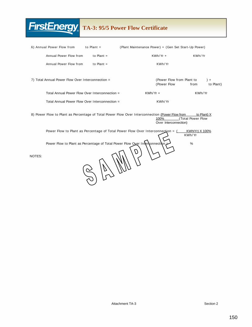
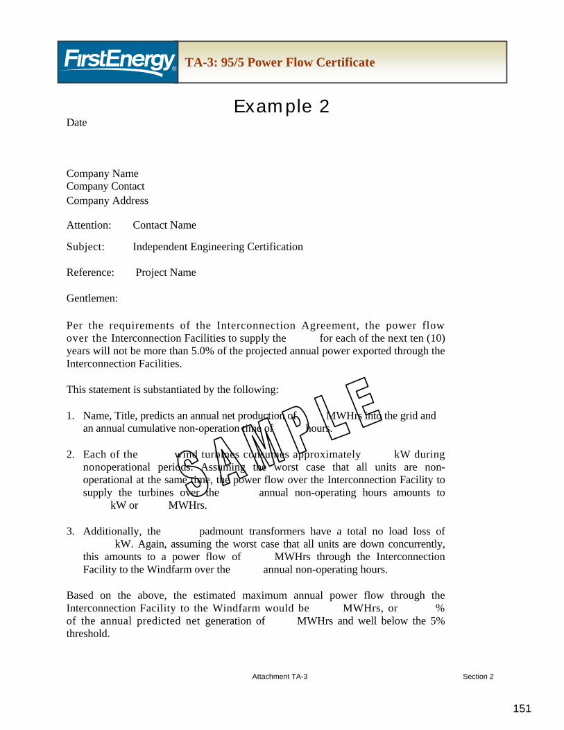
14. 95/5 Power Flow Certificate
14.1. Within 45 days after execution of the CSA/ISA, the IC is to provide the TO with an independent engineering certification (i.e., the professional engineer’s seal shall be affixed), as specified in IRS Notice 88-129, attesting that the anticipated power flows through the Interconnection Facilities to the power producer for the first ten years of operation will comprise no more than 5% of the projected total power flows over the Interconnection Facilities. Please see “FirstEnergy Wholesale Generation Interconnection Requirements – Tax and Accounting” for detailed tax requirements.
15. Field Engineer/Inspector
15.1. The TO may assign a field engineer or field inspector to review the IC’s construction of the Interconnection Facilities. The IC will cooperatively assist the field engineer or field inspector. The TO and the IC will cooperatively attempt to resolve all identified construction inadequacies; however, the TO expressly reserves the right to issue an order to halt part or all of the construction activities if, in its opinion, the Interconnection Facilities construction is not proceeding in accordance with the TO’s accepted design drawings of the facilities. The IC shall comply with all such orders to halt construction activities.
16. Project Change Request Process
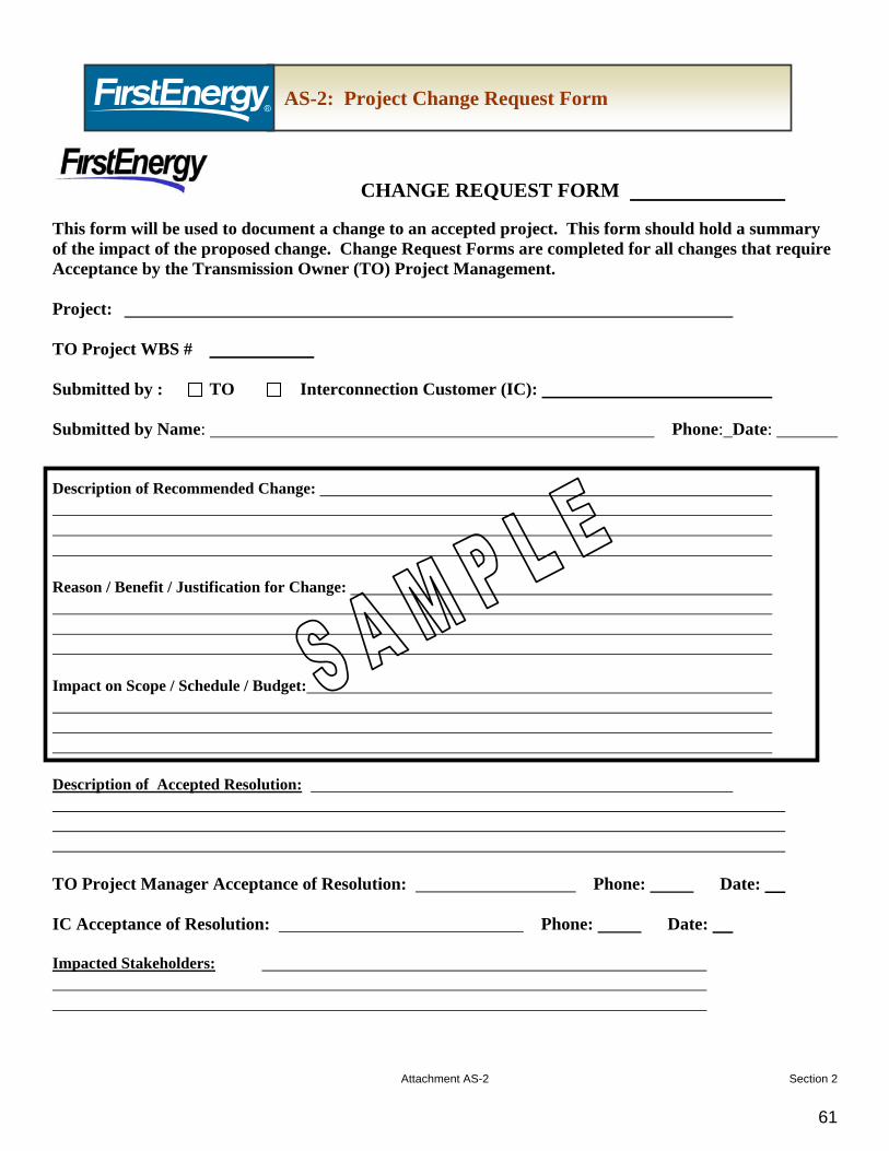
16.1. Once a package or plan has been reviewed and accepted by the TO, a newly proposed change must be submitted through the Project Change Request Form (Attachment AS-2) by the IC. The Project Change Request Form documents the reason for the change and the technical description of the change. Sketches, drawings, and/or similar materials may be attached to the Project Change Request
Form. The IC shall assign a unique sequential number to each Project Change Request Form. Each change shall be submitted to the TO for review and acceptance prior to implementing the project change. The TO will indicate their acceptance with an appropriate indication on a copy of the IC’s submitted documentation. In certain cases, when an emergency construction issue arises, the Project Change Request Form may follow the field action within 24 hours of implementation. In these cases the resolution must have been verbally discussed with mutual agreement to proceed from both the TO and the IC.
16.2. It is anticipated that during the commissioning of the facility, field changes will be required as inspection and testing proceeds. It is critical that all deviations from the submitted and accepted design are recorded on the Project Change Request Form (Attachment AS-2). The IC will be required to submit all Red Line As-Built Drawings and the associated Project Change Request Form(s) that document each of the red-line deviations. The submittal of the Red Line As-Builts and catalog of Accepted Project Change Request Forms are required to be submitted at the following Project Milestones:
16.2.1. Milestone C.37 - Interconnection Customer submits Notice of Completion for Transmission Line and Interconnection Facilities.
16.2.2. Milestone C.44 - Successful Energization of Interconnection Facilities.
16.2.3. Milestone C.47 - Interconnection Customer Submits Bill of Sale & Notice of Transfer of Title to Transmission Owner
17. Outage Scheduling
17.1. FE will apply for the transmission line outage or outages required for the construction of the transmission line connection, and energization of the TO Interconnection Facilities and the IC Interconnection Facilities.
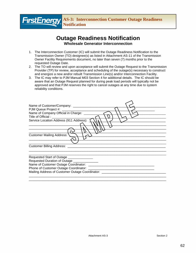
17.2. The IC will submit the Interconnection Customer Outage Readiness Notification to the TO (Attachment AS-3) seven months prior to the requested outage date. This seven month period allows the TO to submit the outage request to the TP for outages greater than five days in duration by the first day of the month, six months prior to the start of the outage in accordance with tariff requirements. The IC should refer to PJM Manual M03 Section 4 for additional outage details.
17.3. In addition, the IC should be aware that outage requests during peak load periods will typically not be approved and that the TP reserves the right to cancel outages at any time due to system reliability conditions.
17.4. If the IC performs a non-direct connection network upgrade under Option to Build, then the IC would need to make an additional outage request to the TO.
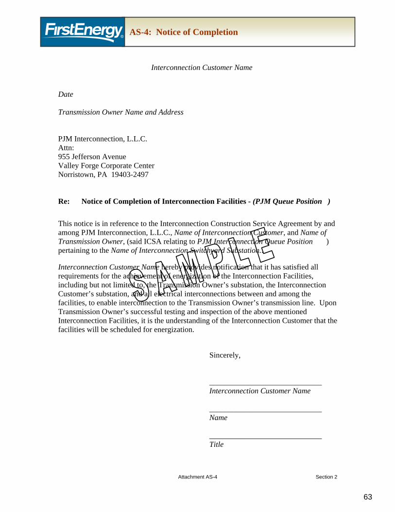
18. Notice of Completion
18.1. The IC shall notify the TP and the TO in writing upon completion of the following:
18.1.1. Customer Facility
18.1.2. The IC Interconnection Facilities
18.1.3. Any TO Facilities for which the IC has completed through exercising the Option to Build alternative. (Attachment AS-4).
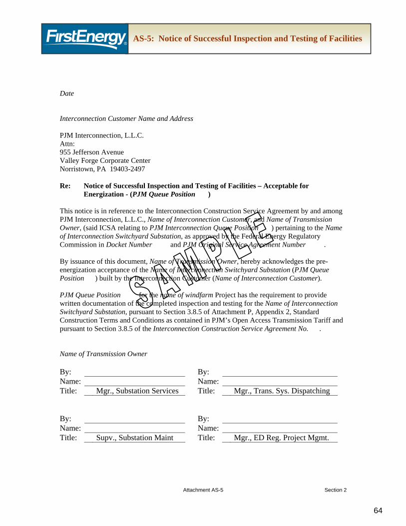
19. Notice of Successful Inspection and Testing of Facilities
19.1. The TO shall issue the Notice of Successful Inspection and Testing of Facilities to the IC within 10 days after satisfactory inspection and/or testing of the Interconnection Facilities built by the IC (Attachment AS-5).
(Reference OATT Att. P, App. 2, Section 3.8.5)
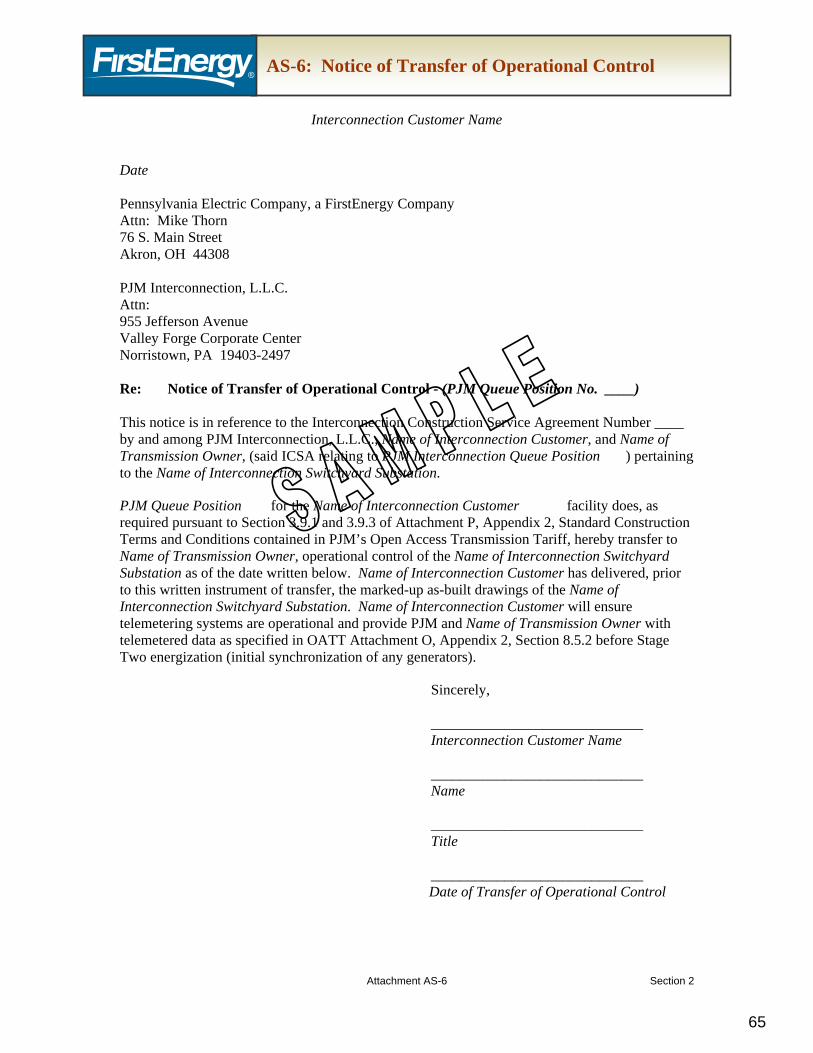
20. The IC must provide verification of successful operation of telemetering systems to the TO prior to energization (Attachment AS-6). (Reference OATT Att. P, App. 2, Section 3.9.3)
21. The IC must provide verification of transfer of all utilities (e.g., phone, water) to the TO.
22. Notice of Transfer of Operational Control
22.1. The IC shall issue the Notice of Transfer of Operational Control to the TO prior to energization (Attachment AS-6).
(Reference OATT Att. P, App. 2, Sections 3.9.1 and 3.9.3)
23. Notice of Acceptance of Facilities
23.1. The TO shall issue a written notice to the IC, within five days after determining that Interconnection Facilities have been successfully energized, accepting the Interconnection Facilities built by the IC. (Attachment AS-7). (Reference OATT Att. P, App. 2, Section 3.10)
24. Notice of Transfer of Title
24.1. The IC shall execute all necessary documentation and shall make all necessary filings to record and perfect the TO’s title in such facilities and in the easements and other land rights to be conveyed to the TO. (Attachment AS-8). Please see “FirstEnergy Wholesale Generation Interconnection Customer Requirements – Real Estate” for detailed property requirements. (Reference OATT Att. P, App. 2, Section 5.5)
25. Bill of Sale
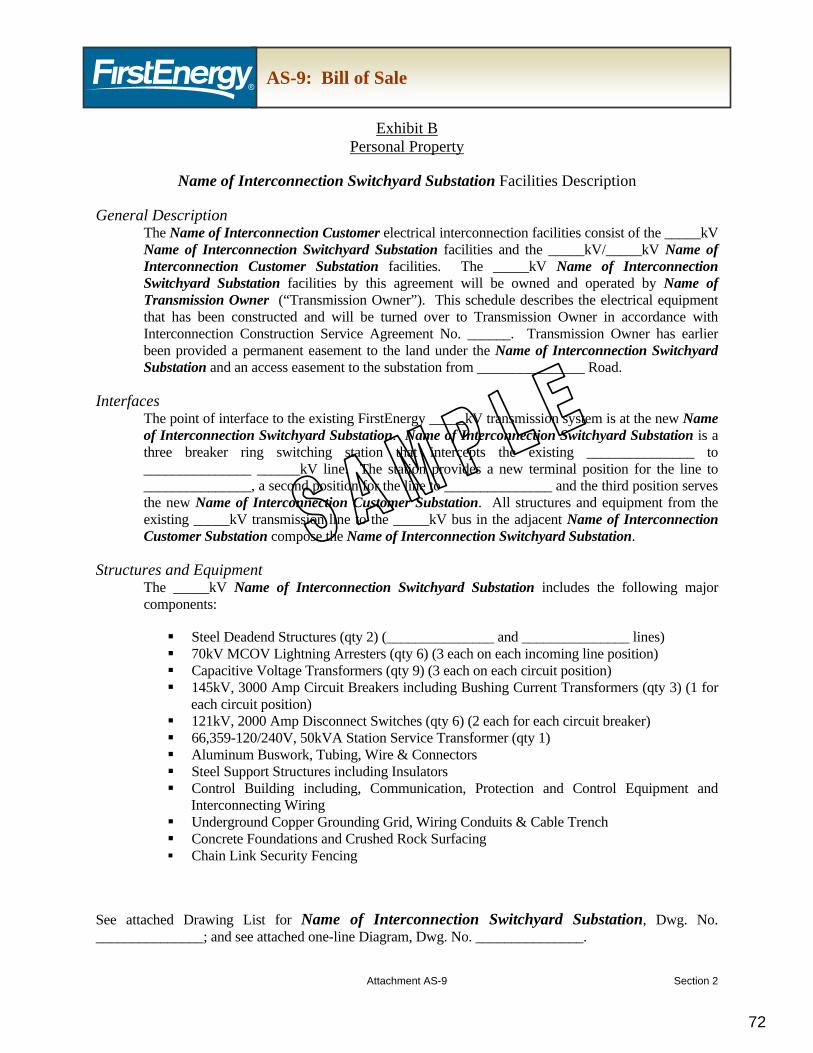
25.1. The IC shall provide the Bill of Sale to the TO with the Notice of Transfer of Title. The Bill of Sale shall include the following as Exhibits: Real Property, Personal Property, Drawing List and One-Line Diagram. (Attachment AS-9). Please see “FirstEnergy Wholesale Generation Interconnection Customer Requirements – Real Estate” for detailed property requirements. (Reference OATT Att. P, App. 2, Section 5.5)
26. Notice of Approval of Documentation
26.1. The TO shall provide written notice of approval of documentation (documented by TO approval of the Bill of Sale) to the IC (such approval not to be unreasonably withheld, delayed, or conditioned). (Attachment AS-9). (Reference OATT Att. P, App. 2, Section 5.5)
27. Maintenance of Access Road
27.1 The access road to the TO substation gate must be maintained by the IC to allow the TO access to the substation at all times, including during inclement weather (e.g., snow clearing during snow events, repairs of erosion due to storm water washout). During a snowfall event where snow accumulation is in excess of four inches, the IC is required to make arrangements to have the access road plowed and salted within a twenty-four hour timeframe. The IC shall provide the TO with the name and contact number (24/7 availability) of the person responsible for coordination of road maintenance in the event the TO requires immediate access to the site. In the event of an emergency situation, the IC is responsible to make arrangements for plow services to clear the road
right of way within one hour’s notice of request by the TO. If it is determined that the IC cannot meet the TO’s requirements, the TO will make arrangements for immediate plow service and the cost associated with that service will be the responsibility of the Interconnection Customer.
28. Applicable Federal Energy Regulatory Commission (FERC) or other regulatory filings
28.1. Within 30 days after the IC’s receipt of the TO’s written notice of approval of the documentation, the IC, in coordination and consultation with the TO, shall make any necessary filings at the FERC or other governmental agencies for regulatory approval of the transfer of title. (Reference OATT Att. P, App. 2, Section 5.5)
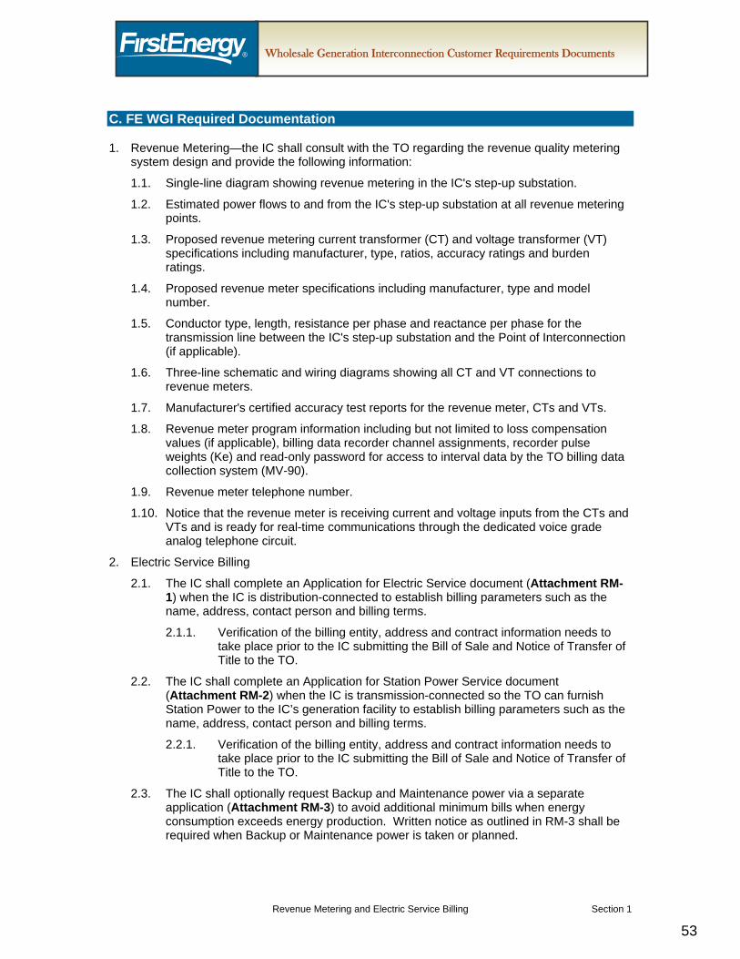
C. FE WGI Required Documentation
1. TO to provide the IC with the following documents:
1.1. See “FirstEnergy Wholesale Generation Interconnection Customer Requirements” for Real Estate, Vegetation Management, Insurance, Regulatory Siting and Environmental Permitting, Substation, Transmission Line, Communications, Revenue Meter and Electric Service, and Tax and Accounting for specific documentation required to be provided by the TO to the IC.
1.2. Project Team Contact List (Attachment AS-1).
1.3. Project Change Request Form (Attachment AS-2).
1. This document contains the Transmission Owner (TO) requirements for wholesale
generation interconnection projects consistent with the interconnection process as defined in the PJM Open Access Transmission Tariff (OATT) and applicable PJM manuals. The purpose of this document and attached checklist is to provide a detailed list of FirstEnergy (FE) requirements, including required documentation for operational and property transfer, if applicable, when a generation interconnection is requested by an Interconnection Customer (IC). These requirements will facilitate the safe, efficient and reliable integration of the Interconnection Facilities into the transmission system.
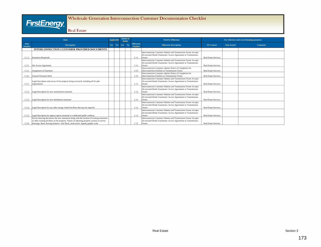
2. The “Wholesale Generation Interconnection Customer Real Estate Documentation Checklist” will be used to track the status of each document.
B. FE WGI Requirements
1. The IC is required to obtain the following documents in the sequence listed below:
1.1. Acquire the Interconnection Facilities property in fee from the property owner
1.2. Acquire an easement from the property owner
1.3. Provide access agreements to the TO from the property owners and IC
1.4. Provide an assignment of appropriate easement rights to the TO upon project completion
1.5. Provide deed conveyance of fee property for the Interconnection Facilities to the TO upon project completion and prior to transfer of title
C. FE WGI Required Documentation
1. Easement (Perpetual)
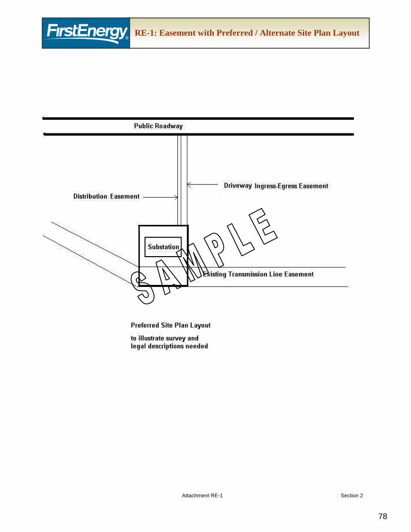
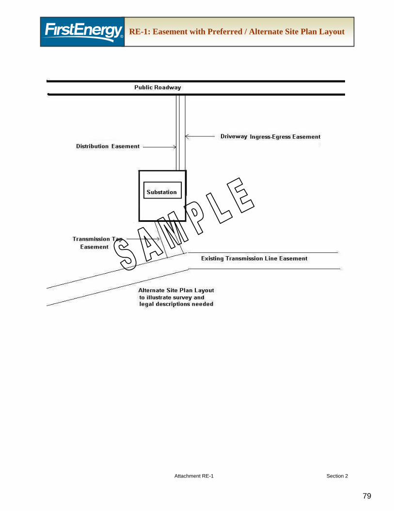
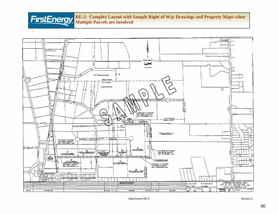
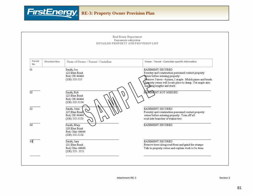
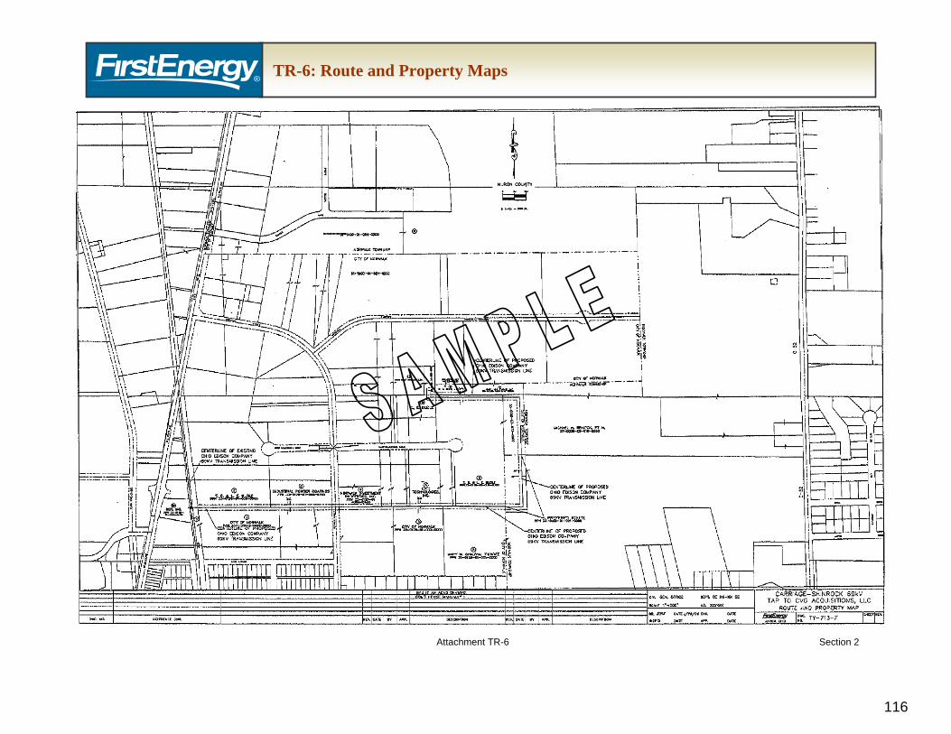
1.1. Legal document that includes descriptions and drawings, as exhibits, defined below in Item 5, Document Exhibits. For an easement and preferred / alternate site plan layout example see Attachment RE-1. If a complex layout involving multiple parcels is necessary, then detailed right-of-way drawing and property maps are required (Attachment RE-2). Additionally, copies of title searches shall be provided to the TO. If a complex layout as shown in Attachment RE-2 is applicable, the IC shall also submit a Property Owner Provision Plan (Attachment RE-3) to the TO.
2. Site Access Agreement
2.1. Legal document that provides the TO rights to perform work on the property prior to owning or recording a conveyed interest in the property (Attachment RE-4). The exhibits to be attached to the Site Access Agreement are further defined in Item 5, Document Exhibits.
3. Assignment of Easement
3.1. Legal document assigning ownership interest in the property to the TO (Attachment RE-5). The exhibits to be attached to the Assignment of Easement are further defined in Item 5, Document Exhibits.
4.1. Legal document conveying fee ownership interest in the property to the TO (Attachment RE-6). The exhibits to be attached to the General Warranty Deed are further defined in Item 5, Document Exhibits.
5. Document Exhibits: IC shall provide a survey and legal description detailing the location of the substation (preferably located adjacent to an existing transmission line easement), ingress-egress to the substation from a dedicated public roadway, and easement for distribution and communication facilities and/or transmission facilities if necessary. This drawing shall be prepared by a licensed and registered surveyor and include at a minimum:
5.1. Legal description and survey of fee property being conveyed, including all lot split requirements
5.1.1. When property is conveyed to the TO by fee, the IC is required to submit a completed Phase I Environmental Site Assessment (ESA) to the TO in accordance with all the requirements outlined in ASTM E 1527-05 prior to the start of construction of a substation property that will be transferred to the TO. Furthermore, if the Phase I ESA completed for the property documents the presence of any recognized environmental conditions (RECs), the IC shall bear the cost and responsibility to complete a Phase II ESA in accordance with ASTM Standard E 1903-97 (Guide for Environmental Site Assessments: Phase II Environmental Site Assessment Process), however, final approval and property conveyance shall be at the sole discretion of the TO.
5.2. Legal description for new transmission easement
5.3. Legal description for new distribution easement
5.4. Legal description for any other energy-related facilities that may be required
5.5. Legal description for ingress-egress easement to a dedicated public roadway
5.6. Survey drawing that shows: 5.6.1. New easements along with the location of existing easements 5.6.2. Other existing facilities on the property 5.6.3. Names of adjoining property owners 5.6.4. Basic drawing features: title block, north arrow, legend, graphic scale
1. This document contains the Transmission Owner (TO) requirements for wholesale
generation interconnection projects consistent with the interconnection process as defined in the PJM Open Access Transmission Tariff (OATT) and applicable PJM manuals. The purpose of this document and attached checklist is to provide a detailed list of FirstEnergy (FE) requirements, including required documentation for operational and property transfer, if applicable, when a generation interconnection is requested by an Interconnection Customer (IC). These requirements will facilitate the safe, efficient and reliable integration of the Interconnection Facilities into the transmission system.
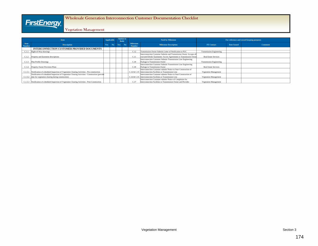
2. The “Wholesale Generation Interconnection Customer Vegetation Management Documentation Checklist” will be used to track the status of each document.
B. FE WGI Requirements
1. The IC shall consult with the TO Vegetation Management representative regarding the scheduling of vegetation clearing activities during the feasibility study, if applicable, and pre-construction (time of engineering design) by defining their work scope of proposed activities or work prescriptions.
2. The proposed Vegetation Management activities for Interconnection Facilities must be performed in accordance with the following:
2.1. Applicable Statutory law and regulations
2.2. Generally accepted industry practices and/or Best Management Practices (BMP) for Integrated Vegetation Management
2.3. Perpetual Easements. Please see “FirstEnergy Wholesale Generation
2.4. Interconnection Customer Requirements – Real Estate Section C. 1.1 Attachment RE-1” for detailed easement language requirements
2.5. NERC Vegetation Management Standard FAC-003-1
2.6. All routine vegetation clearing work is performed in compliance with ANSI Z133.1 and A-300 Standards (along with companion publications for any part regarding Electric Utility Rights-of-Way) and according to the requirements given by OSHA and the National Electrical Safety Code (NESC). Transmission right-of-way projects designed and constructed under the interconnection process that are located in New Jersey requires all debris to be removed within five business days after the vegetation is cut, unless permission is obtained from the property owner to leave vegetation debris. This is in accordance with N.J.A.C 14:5-9.5(g). Take into consideration the time of year being built as vegetation conditions are dynamic and may be restricted due to environmental conditions. (e.g., Indiana bat habitat)
2.7. Contractor personnel shall be properly trained to perform the work proficiently and safely so as to comply with all applicable laws, regulations and local ordinances.
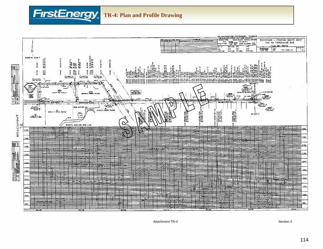
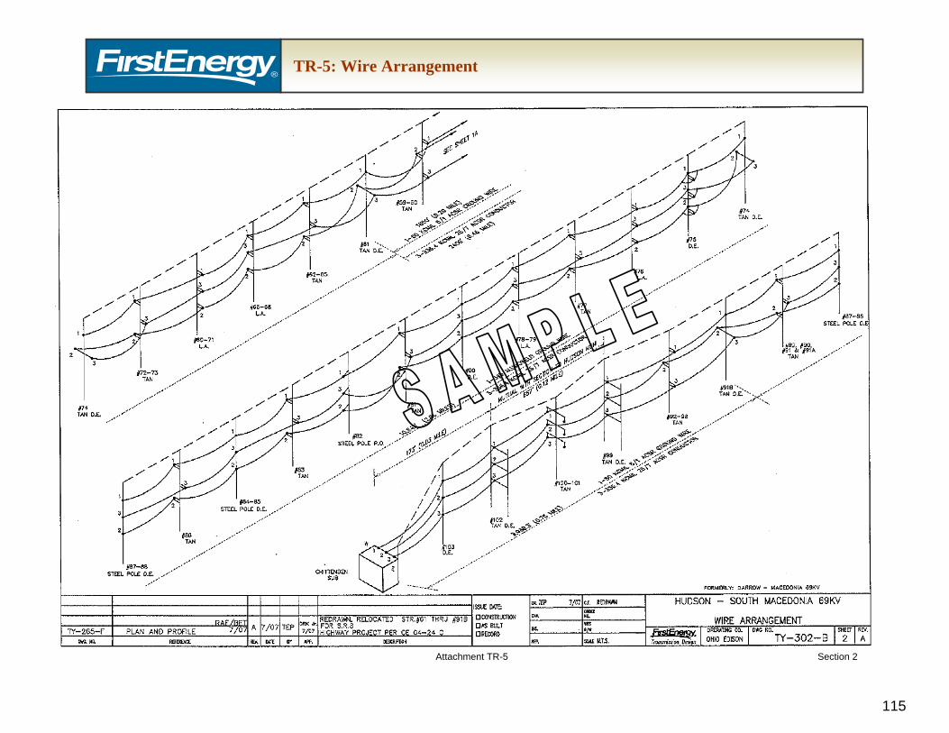
2.8. Plan and Profile Drawings- Please see “FirstEnergy Wholesale Generation Interconnection Customer Requirements – Transmission Line, Section C. 1.1.5” for Plan and Profile Drawing details.
2.9. Right-of-way drawings - Please see “FirstEnergy Wholesale Generation Interconnection Customer Requirements – Transmission Line, Section C. 1.1.8” for Right-of-way Drawing details.
2.10. Property Owner Provision Plan - Please see “FirstEnergy Wholesale Generation Interconnection Customer Requirements – Real Estate, Section C. 1.1 Attachment RE-3” for Property Owner Provision Plan details.
2.10.1. The Property Owner Provision Plan shall detail, if applicable, vegetation activities – manual, mechanical or herbicide.
2.11. A right-of-way clearing zone shall be defined by the voltage and structure type. All trees within the clearing zone shall be cut as close to groundline as possible. The stump will be flush cut no higher than three (3) inches from, and parallel to the ground.
2.12. Trees located outside the clearing zone with limbs extending into the zone will have those limbs removed to the main stem. This will be performed for all limbs on these edge trees regardless of their position along the main stem.
2.13. All trees outside the clearing zone that are dead, dying, diseased, severely leaning or significantly encroaching the right-of-way, have hazardous defects such as obvious decay, uprooting, poor soil conditions, or have lightning, insect, vehicle or animal damage shall be removed.
2.14. Trees, brushwood and slash shall be placed or disposed of as designated by the detailed property and provision list. Accepted TO methods of disposal include windrowing, chipping, lopping, and stacking. Lopping must be below knee height. Brush and logs must not be left in any waterway or within fifteen (15’) feet of the centerline of any distribution line or more than ten feet (10’) from the edge of a transmission line clearing zone or in areas accessible by mechanical equipment. Debris from clearing zone areas that are adjacent to a road shall be kept on the edge of the clearing zone away from the edge of the road.
2.15. Designated trees are to be left in lengths as long as possible, preferably whole tree lengths and shall be placed in neat piles with the tree lengths parallel to and along the edge of the clearing zone corridor and separated from other piles or windrows.
2.16. Slash and brushwood generated from the clearing operation shall be placed in piles or windrows along the edge of the clearing zone corridor and separated from other piles unless otherwise specified. Any disposal of brush, wood, slash, logs or trees shall be in accordance with the laws and regulations of the appropriate governing authority.
2.17. The TO expects all incompatible vegetation on the corridor be controlled with an herbicide treatment, cut surface treatment being the minimum chosen treatment. Herbicide applications are to be made in a manner assuring restriction of applied material to the target. All herbicides shall be applied by the Contractor in accordance with the manufacture’s label instructions. The Contractor shall meet the following requirements when applying herbicides: Hold a current and appropriate pesticide application license from the appropriate State Department of Agriculture or its approved equivalent. Conform to all state, local and federal laws governing the herbicide used. Contractor shall apply all herbicide in a manner assuring restriction of applied material to the right-of-way and shall not contaminate or pollute any water source or body of water.
2.18. The IC is required to arrange a minimum of three inspections with the TO Vegetation Management Representative to review the vegetation clearing activities. The intervals in which these inspections shall take place are pre-construction, during the clearing activities and post-construction.
3. The IC shall provide the TO with prior notification of any modifications of the vegetation clearing activities that will affect the vegetation activities not meeting the written FE standards. The IC shall be required to schedule inspections with a TO Vegetation Management representative to ensure all vegetation activities have been approved and to meet the prescribed standards outlined above. The TO representative will provide the IC with documentation if the work is found not to meet FE standards and or requires any modifications prior to energizing the facilities. The IC will then submit final inspection documents recording the scheduled inspections were completed.
C. FE WGI Required Documentation
1. IC to provide the TO with the following documents:
1.1. Right-of-Way Drawings
1.2. Property and Easement descriptions
1.3. Plan and Profile Drawings
1.4. Property Owner Provision Plans
1.5. Vegetation Clearing Activities Inspections, as stated in Section B.3.
1.5.1. Notification of scheduled Inspection for pre-construction activities
1.5.2. Notification of scheduled Inspection for construction activities (provide date for vegetation clearing during construction)
1.5.3. Notification of scheduled Inspection for post-construction activities
1. This document contains the Transmission Owner (TO) requirements for wholesale generation
interconnection projects consistent with the interconnection process as defined in the PJM Open Access Transmission Tariff (OATT) and applicable PJM manuals. The purpose of this document and attached checklist is to provide a detailed list of FirstEnergy (FE) requirements, including required documentation for operational and property transfer, if applicable, when a generation interconnection is requested by an Interconnection Customer (IC). These requirements will facilitate the safe, efficient and reliable integration of the Interconnection Facilities into the transmission system.
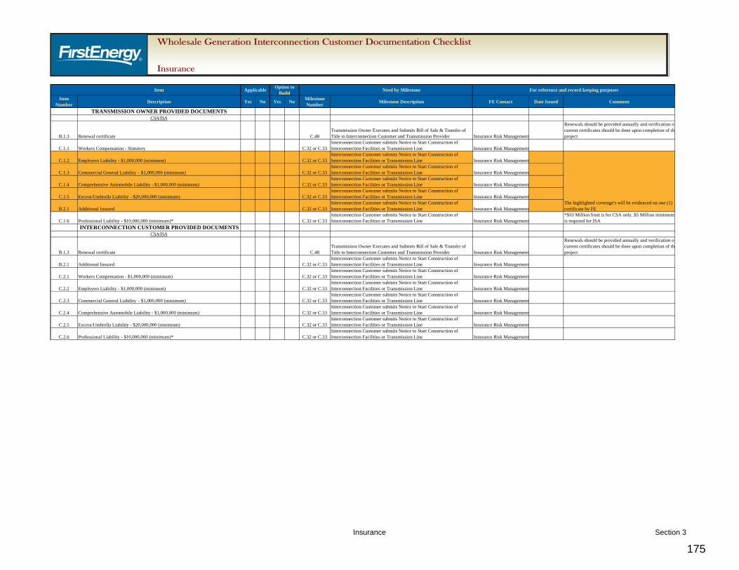
2. The “Wholesale Generation Interconnection Customer Insurance Documentation Checklist” will be used to track the status of each document.
B. FE WGI Requirements
1. Insurance Standards
1.1. Parenthetically referenced agreement sections in this document are from Section 11 and 14 of the Construction Service Agreement (CSA). Corresponding agreement sections from the Interconnection Service Agreement (ISA) are from Section 13 and 16.
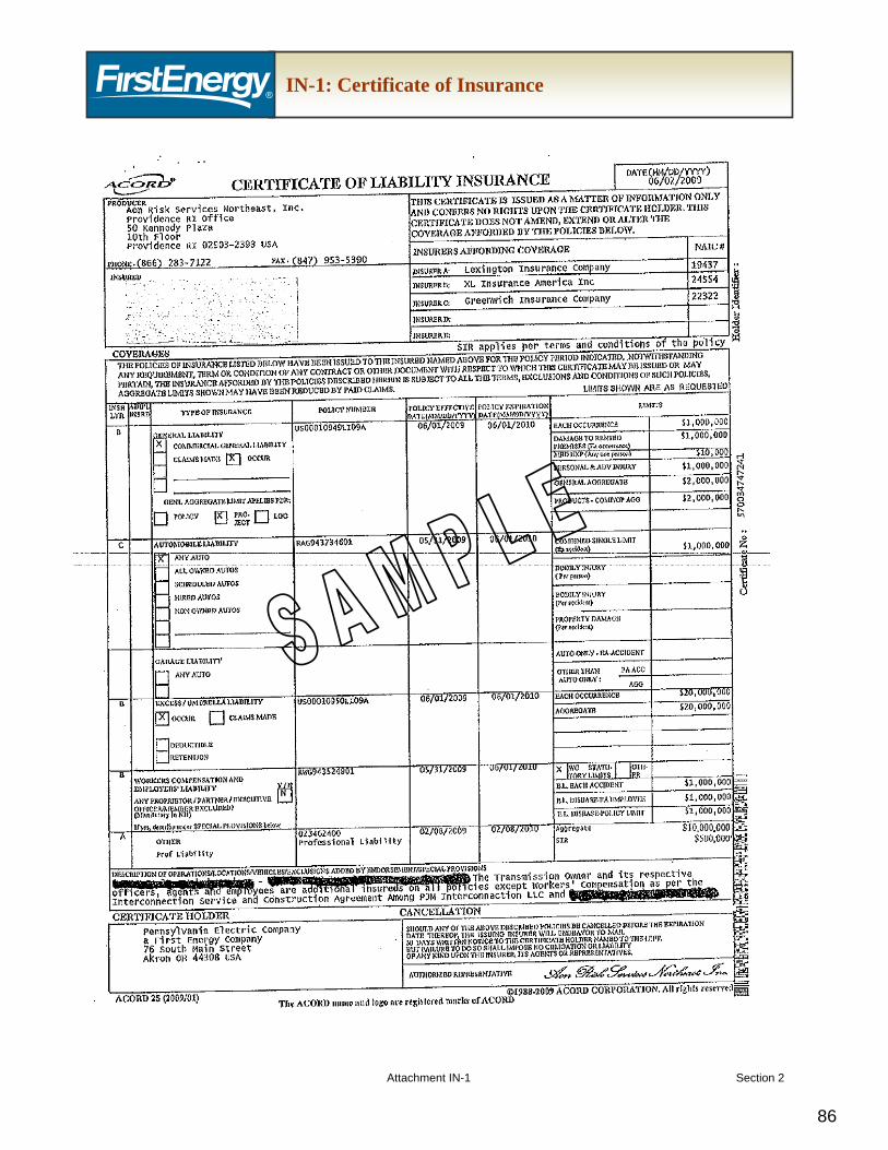
1.2. The IC and the TO are to exchange Certificates of Insurance evidencing the coverages listed below, as required by the CSA and ISA.
1.3. Certificates are required prior to the start of construction of either the Interconnection Facilities or Transmission Line, and shall be provided annually until the termination of the respective agreement.
1.4. If the insurance policy is written on a “Claims First Made Basis,” it must remain in effect for two (2) years after the termination of the respective agreement (CSA, Appendix 2, Section 11.3.b and Section 14).
1.5. Required coverage levels are the same for the ISA and CSA with the exception of Professional Liability (see below). These may be evidenced on one certificate (Attachment IN-1). If one certificate is submitted for both the CSA and the ISA, the IC must reference both the CSA and the ISA on the certificate, as well as the PJM Project Queue Number.
1.6. Each entity is responsible for verifying that all subcontractors have insurance commensurate with the risks associated with the services they are providing.
1.7. In the event that these conditions cannot be met, contact the TO Corporate Insurance Risk Representative for further guidance.
2. General Policy Requirements
2.1. Each Entity shall include each other’s Party as additional insureds to the General Liability, Automobile Liability and Excess/Umbrella Liability policies (CSA, Appendix 2, Section 11.2)
2.2. Policies shall contain a provision specifying it is primary without consideration for other policies separately carried (CSA, Appendix 2, Section 11.3.a)
2.3. Policies shall contain a waiver of all rights of subrogation (CSA, Appendix 2, Section 11.3.c)
2.4. All insurance must be obtained from insurers that have an AM Best rating of “A-” or better. (CSA, Appendix 2, Section 11.1)
3. Requirements for Self-Insurance
3.1. The entities may meet the requirements in Section C by self-insuring themselves provided that they meet the requirements below (CSA, Appendix 2, Section 11.4)
3.1.1. Entity’s senior secured debt must be rated investment grade or better by Standard & Poor’s.
3.1.2. Self-insurance program must meet the minimum requirements set forth in CSA, Appendix 2, Section 11.
C. FE WGI Required Documentation
1. TO to provide the IC with the following documents:
1.1. Workers Compensation meeting state required statutory limits of the work site (CSA, Appendix 2, Section 11.1.A)
1.2. Employers Liability Insurance with minimum limits of one million dollars ($1,000,000) (CSA, Appendix 2, Section 11.1.A)
1.3. Commercial General Liability Insurance with minimum limits of one million dollars ($1,000,000) per occurrence and in the aggregate (CSA, Appendix 2, Section 11.1.B)
1.4. Comprehensive Automobile Liability Insurance with minimum limits of one million dollars ($1,000,000) per occurrence (CSA, Appendix 2, Section 11.1.C)
1.4.1. Must include coverage for owned and non-owned hired vehicles, trailers or semi-trailers designed for travel on public roads
1.5. Excess/Umbrella Liability Insurance with a limit of twenty million dollars ($20,000,000) per occurrence (CSA, Appendix 2, Section 11.1.D)
1.6. Professional Liability with a limit of ten million dollars ($10,000,000) per occurrence and in the aggregate for the CSA (CSA, Appendix 2, Section 11.1.E) and five million dollars ($5,000,000) per occurrence and in the aggregate for the ISA (ISA, Appendix 2, Section 13.1.E).
1.6.1. This requirement may be satisfied by requiring third-party contractors, designers, engineers or other parties who are responsible for design work associated with the facilities necessary for the interconnection to procure in the amounts stated above.
2. IC to provide the TO with the following documents:
2.1. Workers Compensation meeting state required statutory limits of the work site (CSA, Appendix 2, Section 11.1.A)
2.2. Employers Liability Insurance with minimum limits of one million dollars ($1,000,000) (CSA, Appendix 2, Section 11.1.A)
2.3. Commercial General Liability Insurance with minimum limits of one million dollars ($1,000,000) per occurrence and in the aggregate (CSA, Appendix 2, Section 11.1.B)
2.4. Comprehensive Automobile Liability Insurance with minimum limits of one million dollars ($1,000,000) per occurrence (CSA, Appendix 2, Section 11.1.C)
2.4.1. Must include coverage for owned and non-owned hired vehicles, trailers or semi-trailers designed for travel on public roads
2.5. Excess/Umbrella Liability Insurance with a limit of twenty million dollars ($20,000,000) per occurrence (CSA, Appendix 2, Section 11.1.D)
2.6. Professional Liability with a limit of ten million dollars ($10,000,000) per occurrence and in the aggregate for the CSA (CSA, Appendix 2, Section 11.1.E) and five million dollars ($5,000,000) per occurrence and in the aggregate for the ISA (ISA, Appendix 2, Section 13.1.E).
2.6.1. This requirement may be satisfied by requiring third-party contractors, designers, engineers or other parties who are responsible for design work associated with the facilities necessary for the interconnection to procure in the amounts stated above.
Regulatory Siting and Environmental Permitting A. Scope 1. This document contains the Transmission Owner (TO) requirements for wholesale
generation interconnection projects consistent with the interconnection process as defined in the PJM Open Access Transmission Tariff (OATT) and applicable PJM manuals. The purpose of this document and attached checklist is to provide a detailed list of FirstEnergy (FE) requirements, including required documentation for operational and property transfer, if applicable, when a generation interconnection is requested by an Interconnection Customer (IC). These requirements will facilitate the safe, efficient and reliable integration of the Interconnection Facilities into the transmission system.
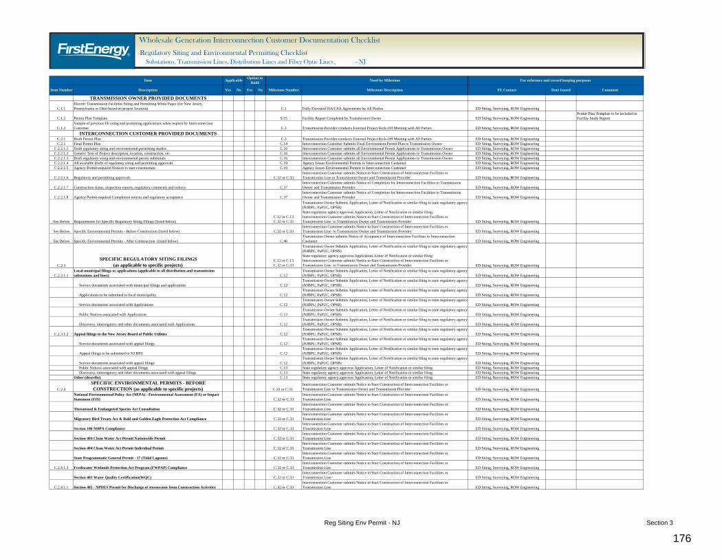
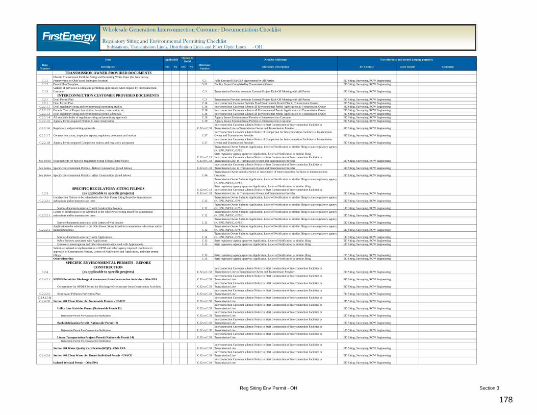
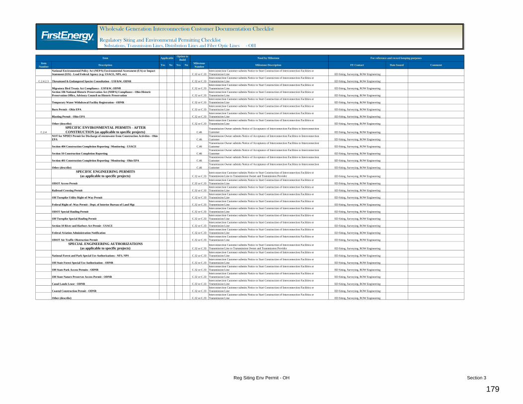
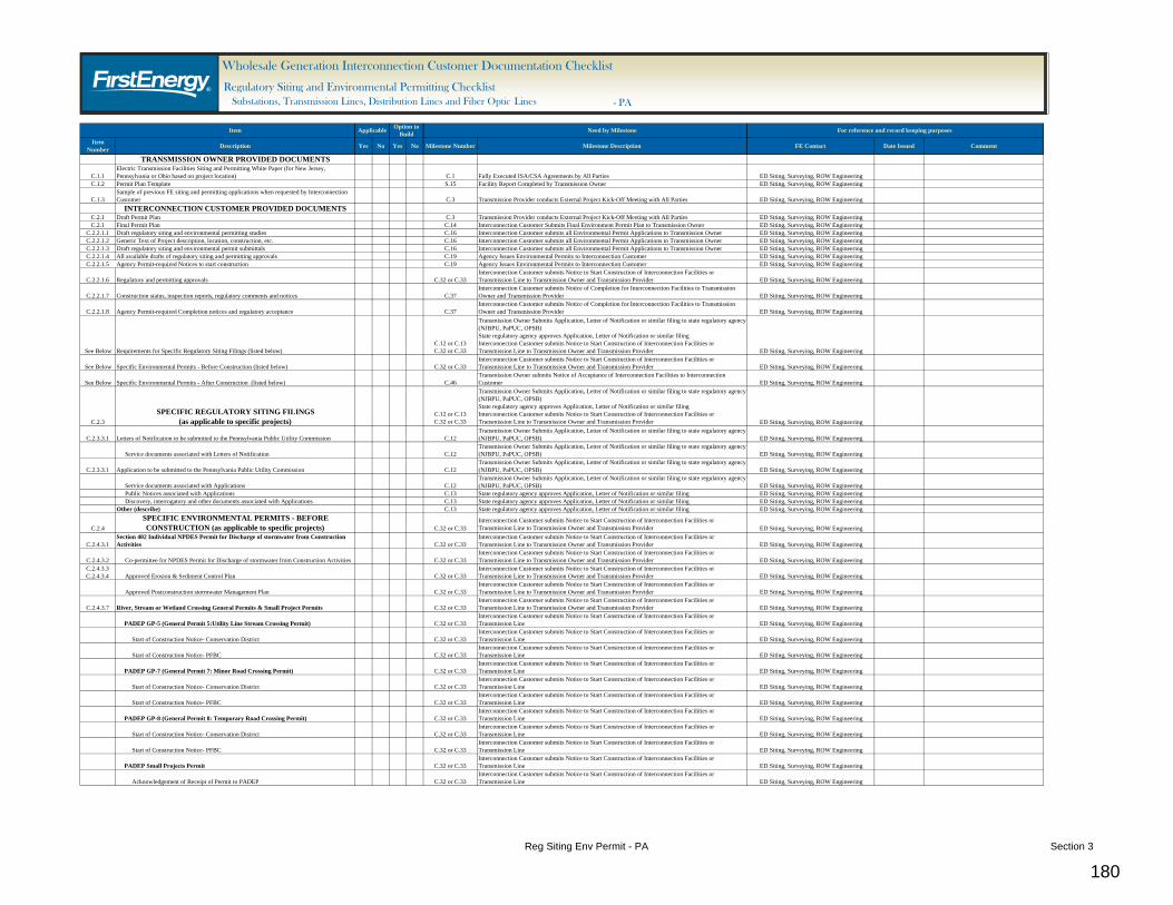
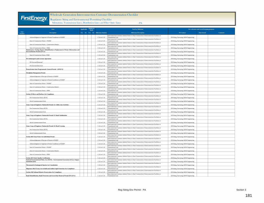
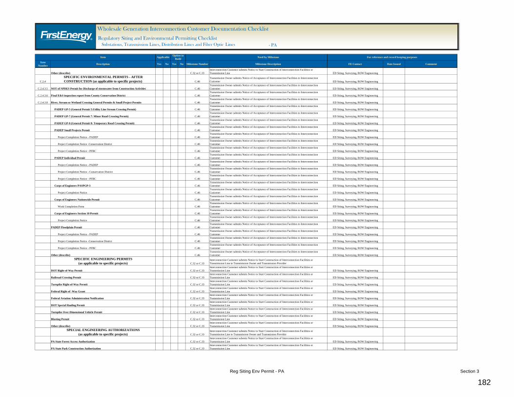
2. The “Wholesale Generation Interconnection Customer Regulatory Siting and Environmental Permitting Documentation Checklist” will be used to track the status of each document.
B. FE WGI Requirements
1. The IC must obtain all regulatory siting approvals and environmental permits that are
applicable to both the facilities to be installed by the IC and the proposed Interconnection Facilities to be installed by the TO in accordance with all applicable regulations, rules and laws. There are three aspects of the intent of this requirement:
1.1. Where siting approvals, environmental permits and associated studies are required by the approving agency to encompass the entire project or facility, the intent is for the IC to conduct the necessary studies and obtain the necessary approvals. (For example, if the IC’s installed facilities require Threatened & Endangered Species Act Consultation, it would be expected that the IC’s actions would also include consideration of the Interconnection Facilities located within or in close proximity to the IC’s installed facilities as a part of the evaluation.)
1.2. Where applicable siting approvals and environmental permits being obtained by the IC must be obtained prior to starting any project or site construction activities, the IC must obtain those approvals and permits before the TO starts its construction activities. (For example, if the regulatory approval for a generation facility includes the associated substation that is being installed as a part of the Interconnection Facilities, the TO would not start construction of the substation until the IC has obtain the regulatory approval.)
1.3. Where the IC will construct or prepare a portion of the project for the TO’s subsequent installation of the Interconnection Facilities, the IC will obtain the necessary siting approvals and environmental permits. (For example, if the IC is providing a graded site for the TO’s installation of a substation, the IC would obtain the necessary permit for discharge of storm water from construction activities.)
2. Under the Option to Build process, except for filings with the Pennsylvania Public Utility
Commission, the IC must obtain all applicable regulatory siting approvals and environmental permits for the proposed Interconnection Facilities in accordance with all applicable regulations, rules and laws.
2.1. For filings with the Pennsylvania Public Utility Commission, the IC will prepare the filings, incorporating the TO’s comments and other requirements, for the TO’s submittal to the Pennsylvania Public Utility Commission.
Regulatory Siting and Environmental Permitting Section 1 26
3. For regulatory siting approvals and environmental permits that are applicable to both the facilities to be installed by the IC and the proposed Interconnection Facilities to be installed by the TO, the IC shall provide the TO with the opportunity to review and accept the portions of the regulatory siting and environmental permitting documents describing the Interconnection Facilities.
4. Under the Option to Build process, the IC shall provide the TO with the opportunity to review
and accept the regulatory siting and environmental permitting documents and agreements as if the TO had implemented the regulatory siting and environmental permitting process.
5. Prior to accepting any regulatory siting or environmental permitting approvals applicable to
both the facilities to be installed by the IC and the proposed Interconnection Facilities to be installed by the TO, or under the Option to Build process, the IC shall provide a draft copy of such approvals (to the extent they exist) or agency-issued approval documents within 48 hours of the issuance of the document for the TO’s review and acceptance. In the event that the TO objects to any conditions or other aspects of the approval and requests the IC to oppose such, the IC shall employ their best efforts to resolve such issues, including appeals of such approvals allowed under existing statutes.
C. FE WGI Required Documentation
1. TO to provide the IC with the following documents:
1.1. The TO will provide a Regulatory Siting and Environmental Permitting White Paper for the state (New Jersey, Pennsylvania or Ohio) where the project is located.
1.1.1. The White Paper is designed to help the TO staff plan and manage the development of transmission and distribution lines and substations. The White Paper may assist the IC to become aware of the regulatory and permitting requirements to extend, connect to, or modify transmission and distribution facilities.
1.1.2. IC should note the White Paper is intended only to provide general guidelines about the regulatory and permitting process that may be required to install facilities connected to transmission and distribution systems. The White Paper is not intended to be, nor is it a substitute to the IC’s careful and independent consideration, identification and evaluation of all applicable regulatory and permitting processes that may be required for a facility to be installed by the IC or installed by others. The IC is strongly advised to pursue this necessary careful and independent evaluation, and the TO will accept no responsibility for the IC’s failure to do so, or for any interpretation of data collected in the IC’s evaluation.
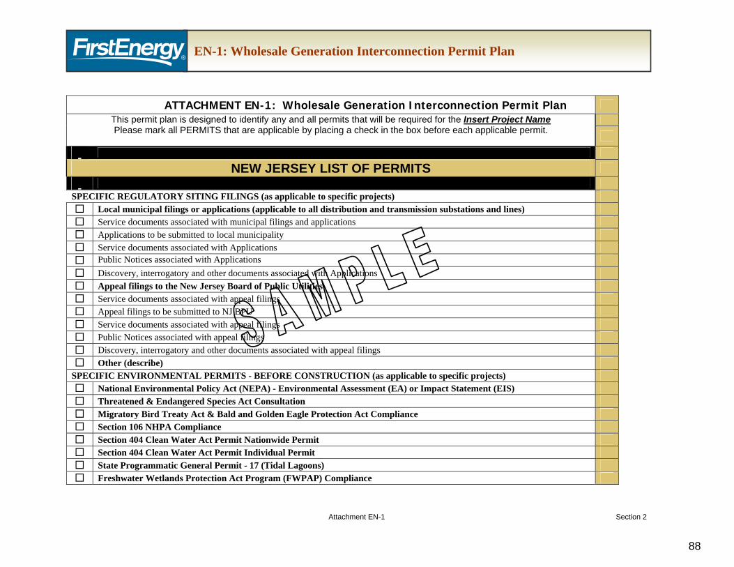
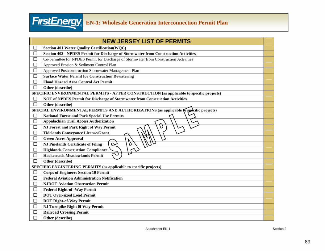
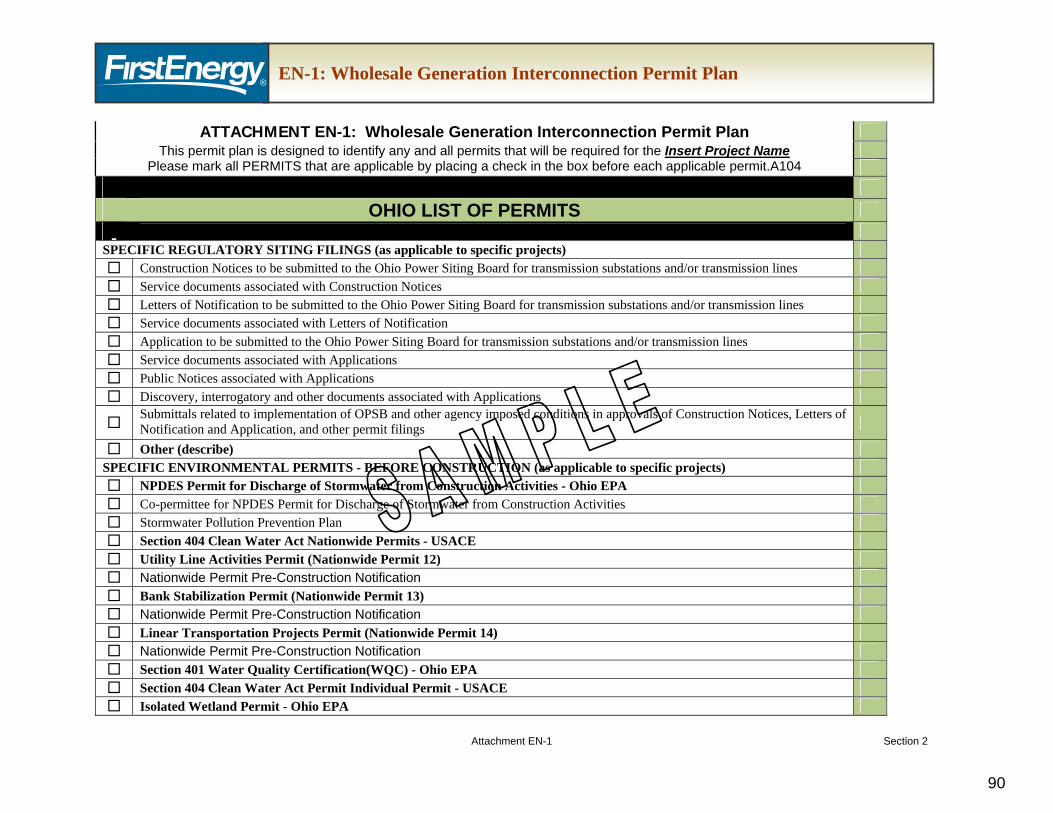
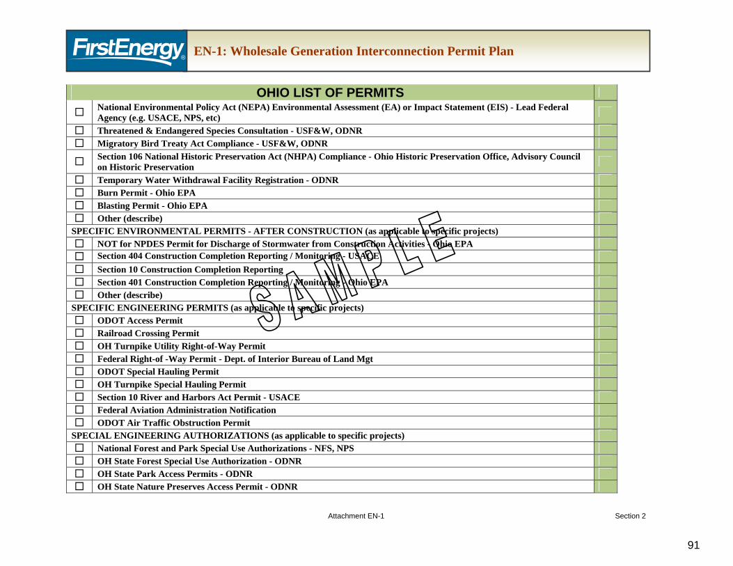
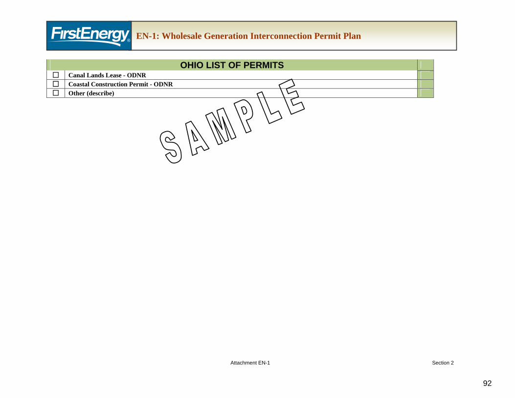
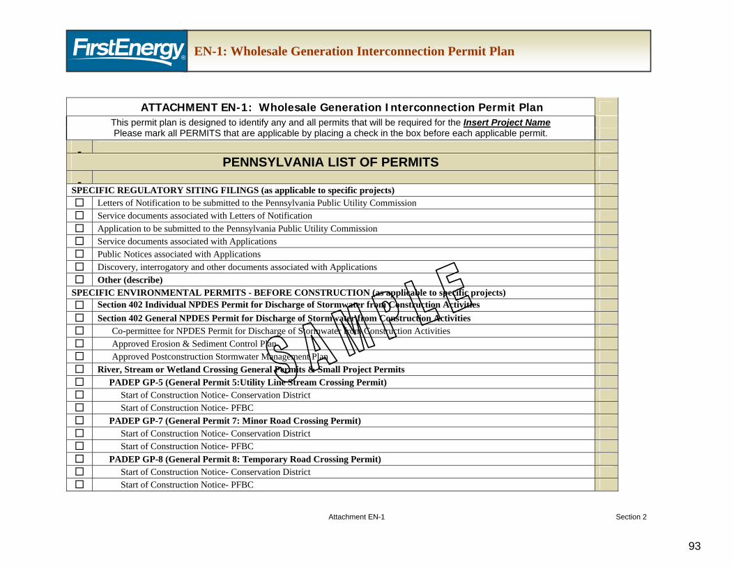
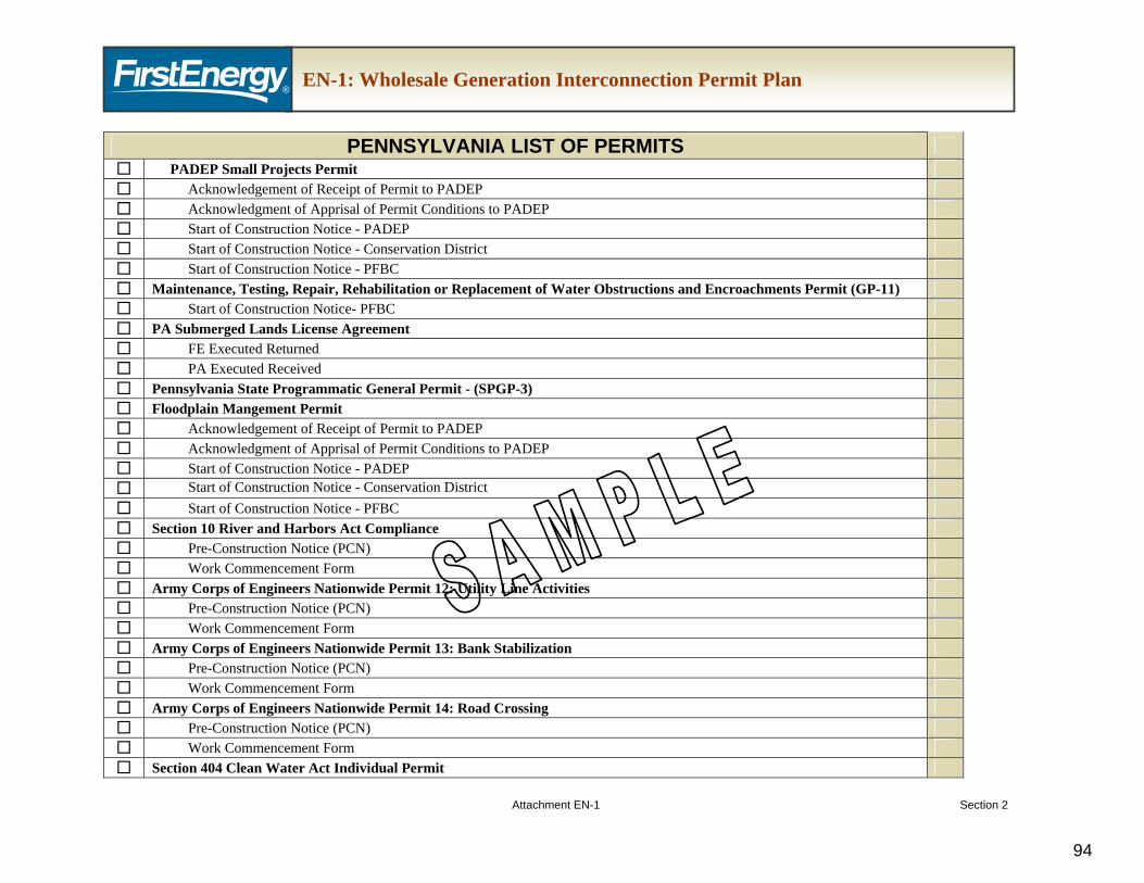
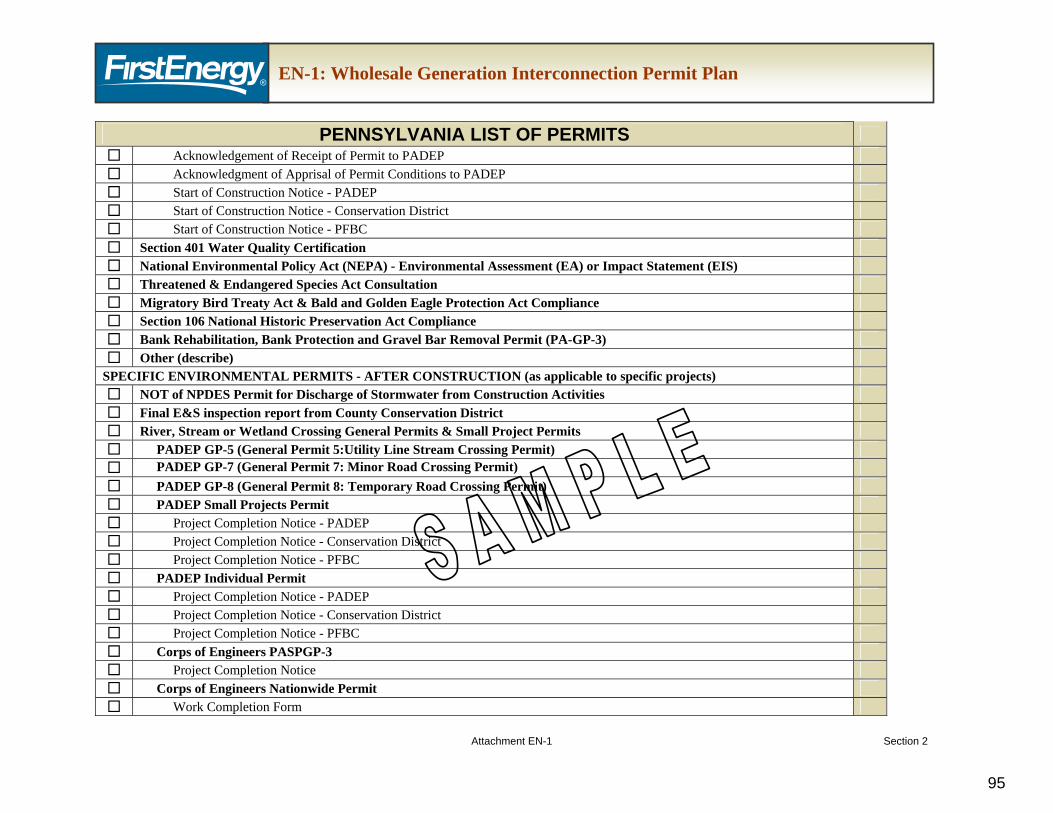
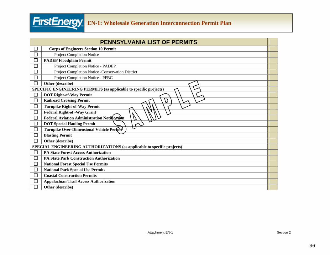
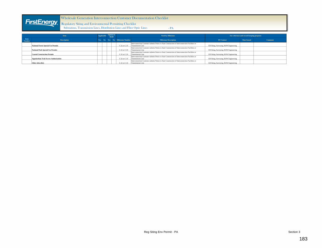
1.1.3. The siting approvals and permits listed in the checklist, as well as the Wholesale Generation Interconnection Permit Plan (Attachment EN-1), are based on the White Papers.
1.2. The TO will provide a permit plan template (Attachment EN-1) with the issuance of the Facilities Study Report. This plan provides a list of potential regulatory siting approvals and environmental permits that may be required for the IC’s specific facilities to be constructed under the Option to Build. The IC will use this plan as part of its developed draft and final permit plans that identify all required permits and regulatory siting approvals, and an associated schedule, that are applicable to both
Regulatory Siting and Environmental Permitting Section 1 27
the facilities to be installed by the IC and the Interconnection Facilities to be installed by the TO, or for the specific facilities to be constructed by the IC under the Option to Build for the project.
1.3. After the IC has identified the required regulatory siting approvals and environmental permitting, the IC may request a sample copy of similar siting and permitting applications previously submitted by the TO for a similar project. The TO shall provide one redacted copy, or identify the public record location, of a similar submittal to the extent that such submittal exists, is readily available and is available in the public domain.
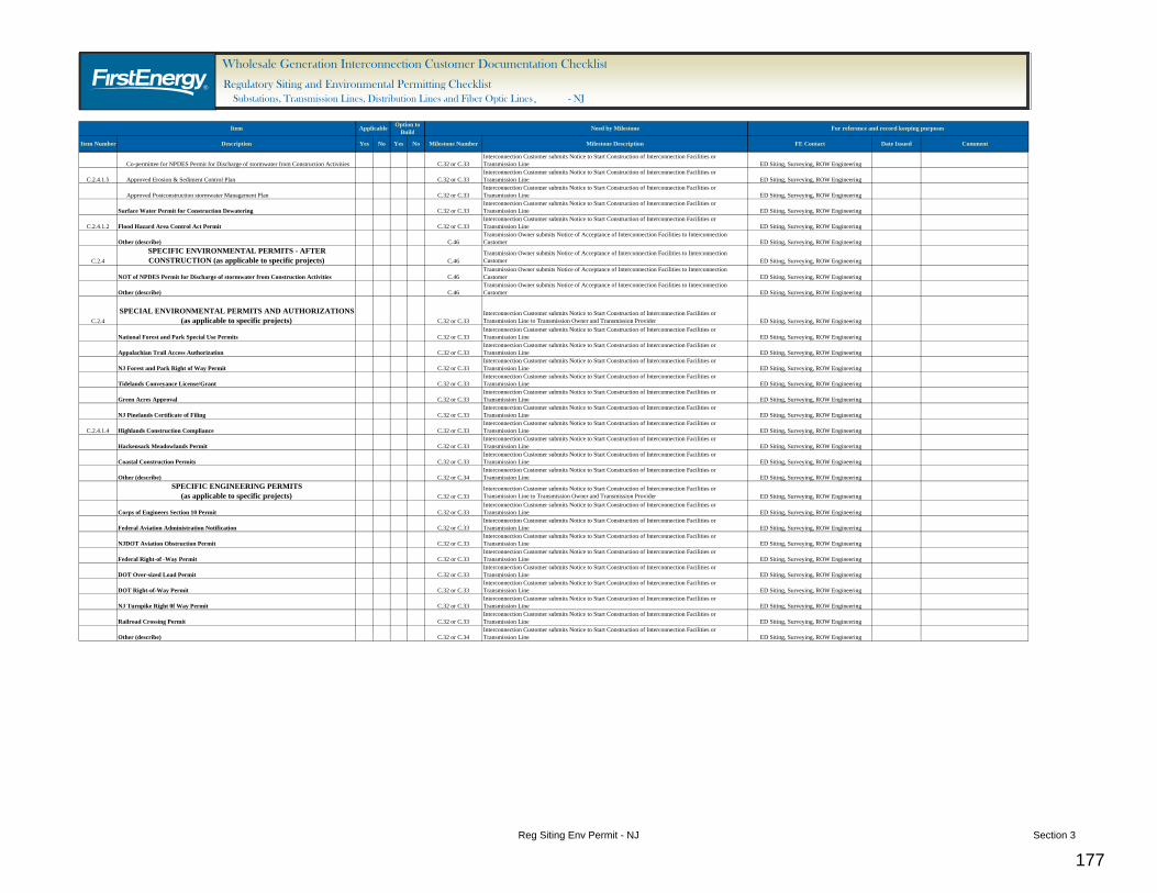
1.4. The IC should also note that some “permitting,” such as railroad crossing permits, highway crossing permits, FAA permits, and US Army Corps of Engineers permits are considered by the TO to be engineering permits. Please see “FirstEnergy Wholesale Generation Interconnection Customer Requirements – Transmission Line” for detailed engineering permitting requirements. The Wholesale Generation Interconnect Permit Plan (Attachment EN-1) includes these engineering permits. In preparing their draft and final permit plans, the IC should indicate the engineering permits required that are applicable to both the facilities to be installed by the IC and the Interconnection Facilities to be installed by the TO, or for the specific IC facilities to be constructed by the IC under the Option to Build for the project.
2. IC to provide the TO with the following documents:
2.1. Seven days prior to the external project kick-off meeting, the IC shall submit a draft permit plan for the TO’s review and for discussion at the kick-off meeting. The IC will prepare and submit a final permit plan within 30 days after the project kick-off meeting. A permit plan shall include the following:
2.1.1. A list of all regulatory siting approvals and engineering and environmental permits that the IC believes are required that are applicable to both the facilities to be installed by the IC and the Interconnection Facilities to be installed by the TO, or for the specific facilities to be constructed by the IC under the Option to Build for the project. (The required regulatory siting approvals and engineering and environmental permits can be indicated by placing a check in the box before each applicable permit listed in Attachment EN-1, the Wholesale Generation Interconnect Permit Plan.)
2.1.2. A schedule indicating the duration and time frame for the necessary studies, preparation of the submittals, the TO’s review of the submittals, and the regulatory submittal and review process. (The required schedule can be provided in a bar chart, as a detailed narrative, or prepared with project scheduling software.)
Note: The IC shall revise the list and schedule and resubmit the permit plan, as necessary, until the TO’s acceptance is obtained.
2.2. Documents Submitted for Review and Acceptance
2.2.1. For regulatory siting approvals and environmental permits that are applicable to both the facilities to be installed by the IC and the Interconnection Facilities to be installed by the TO:
2.2.1.1. The IC shall provide a draft copy of the portion of all office and field studies that describe the Interconnection Facilities to be installed by the TO, prepared in support of any regulatory siting and environmental permitting for the TO’s review and acceptance, and
Regulatory Siting and Environmental Permitting Section 1 28
shall resubmit the documents as necessary until the TO’s acceptance is obtained.
2.2.1.2. The IC shall provide a draft copy of the description, location, and any description of the IC’s construction and the TO’s future ownership of the project (“Generic Text”) that will be used in any and all informational requests to local, state or federal agencies prepared in support of any regulatory siting and environmental permitting for the TO’s review and acceptance, and shall resubmit the documents as necessary until the TO’s acceptance is obtained. In order to minimize the time and effort to review multiple documents, the intent is for the IC to submit one Generic Text that describes the project for the TO’s review. After the TO’s acceptance is obtained, this Generic Text will be used by the IC in all subsequent submittals. In the event that the Generic Text must be revised, the revised Generic Text will also be submitted for the TO’s review and acceptance.
2.2.1.3. The IC shall provide a draft copy of the portion of all regulatory siting and environmental permitting submittals and related correspondence that describe the Interconnection Facilities to be installed by the TO prepared in support of any regulatory siting and environmental permitting for the TO’s review and acceptance, and shall resubmit the documents as necessary until the TO’s acceptance is obtained.
2.2.1.4. Prior to accepting any regulatory siting or environmental permitting approvals that involve the Interconnection Facilities to be installed by the TO, the IC shall provide a draft copy of such approvals (to the extent they exist) or the final agency document for any regulatory siting and environmental permitting for the TO’s review and acceptance. In the event that the TO objects to any conditions or other aspects of the approval and asks the IC to oppose such, the IC shall employ their best efforts to resolve such concerns, including appeals of such approvals allowed under existing statutes.
2.2.1.5. The IC shall promptly provide the TO with copies of all agency permit-required start-of-construction notices that involve the Interconnection Facilities to be installed by the TO.
2.2.1.6. The IC shall provide the TO with a copy of all obtained regulatory siting and environmental permitting approvals that involve the Interconnection Facilities to be installed by the TO within 48 hours of obtaining such approval, and prior to submittal of agency permit-required Notices to Start Construction, or prior to starting construction of the interconnection facilities when an agency permit-required Notice to Start Construction is not required.
2.2.1.7. The IC shall promptly provide the TO with copies of all field inspection reports, regulatory comments on construction or notices of deficiency and similar documents associated with the regulatory siting and environmental permitting of the Interconnection Facilities to be installed by the TO.
2.2.1.8. The IC shall promptly provide the TO with copies of all agency permit-required completion notices and regulatory acceptance of
Regulatory Siting and Environmental Permitting Section 1 29
completion of construction notices that involve the Interconnection Facilities to be installed by the TO.
2.2.2. For the specific IC facilities to be constructed by the IC under the Option to Build for the project:
2.2.2.1. The IC shall provide a draft copy of all office and field studies prepared in support of any regulatory siting and environmental permitting for the TO’s review and acceptance, and shall resubmit the documents as necessary until the TO’s acceptance is obtained.
2.2.2.2. The IC shall provide a draft copy of the description of the project, the location of the project, and any description of the IC’s construction and the TO’s future ownership of the project (“Generic Text”) that will be used in any and all informational requests to local, state or federal agencies prepared in support of any regulatory siting and environmental permitting for the TO’s review and acceptance, and shall resubmit the documents as necessary until the TO’s acceptance is obtained. In order to minimize the time and effort to review multiple documents, the intent is for the IC to submit one Generic Text that describes the project for the TO’s review. After the TO’s acceptance is obtained, this Generic Text will be used by the IC in all subsequent submittals. In the event that the Generic Text must be revised, the revised Generic Text will also be submitted for the TO’s review and acceptance.
2.2.2.3. The IC shall provide a draft copy of all regulatory siting and environmental permitting submittals and related correspondence prepared in support of any regulatory siting and environmental permitting for the TO’s review and acceptance, and shall resubmit the documents as necessary until the TO’s acceptance is obtained.
2.2.2.4. Prior to accepting any regulatory siting or environmental permitting approvals, the IC shall provide a draft copy of such approvals (to the extent they exist) or the final agency document for any regulatory siting and environmental permitting for the TO’s review and acceptance. In the event that the TO objects to any conditions or other aspects of the approval and asks the IC to oppose such, the IC shall employ their best efforts to resolve such concerns, including appeals of such approvals allowed under existing statutes.
2.2.2.5. The IC shall promptly provide the TO with copies of all agency permit-required start-of-construction notices.
2.2.2.6. The IC shall provide the TO with a copy of all obtained regulatory siting and environmental permitting approvals within 48 hours of obtaining such approval, and prior to submittal of agency permit-required Notices to Start Construction, or prior to starting construction of the interconnection facilities when an agency permit-required Notice to Start Construction is not required.
2.2.2.7. The IC shall promptly provide the TO with copies of all field inspection reports, regulatory comments on construction or notices of deficiency and similar documents associated with the regulatory siting and environmental permitting of the facility.
Regulatory Siting and Environmental Permitting Section 1 30
2.2.2.8. The IC shall promptly provide the TO with copies of all agency permit-required completion notices and regulatory acceptance of completion notices of construction.
2.3. The more common regulatory siting filings include:
2.3.1. New Jersey
2.3.1.1. Local municipal filings or applications (applicable to all distribution and transmission voltage lines)
2.3.1.2. Appeal filings to the New Jersey Board of Public Utilities
2.3.2. Ohio
2.3.2.1. Ohio Power Siting Board application, Letter of Notification, or Construction Notice for 125 kV and higher designed and constructed transmission lines
2.3.2.2. Ohio Power Siting Board application, Letter of Notification, or Construction Notice for transmission substations
2.3.3. Pennsylvania
2.3.3.1. Pennsylvania Public Utility Commission application or Letter of Notification for 100 kV and higher designed and constructed transmission lines
2.4. The more common environmental permits include:
2.4.1. New Jersey
2.4.1.1. National Pollutant Discharge Elimination System (NPDES) permit for discharge of storm water from construction activities
2.4.1.2. Flood Hazard Area Permit
2.4.1.3. Freshwater Wetlands Permit
2.4.1.4. Highlands Exemption
2.4.1.5. Erosion & Sediment Control Plan Approval
2.4.2. Ohio
2.4.2.1. National Pollutant Discharge Elimination System (NPDES) permit for discharge of storm water from construction activities
2.4.2.2. Storm water Pollution Prevention Plan
2.4.2.3. Threatened & Endangered Species Consultation – US Fish & Wildlife Service, Ohio Dept. of Natural Resources
2.4.2.4. Section 404 Clean Water Act Water Act Permit - US Army Corps of Engineers
2.4.2.5. Nationwide Permit – US Army Corps of Engineers
2.4.2.6. Pre-Construction Notification – US Army Corps of Engineers
2.4.3. Pennsylvania
2.4.3.1. National Pollutant Discharge Elimination System (NPDES) permit for discharge of storm water from construction activities
Regulatory Siting and Environmental Permitting Section 1 31
Substation A. Scope 1. This document contains the Transmission Owner (TO) requirements for wholesale generation
interconnection projects consistent with the interconnection process as defined in the PJM Open Access Transmission Tariff (OATT) and applicable PJM manuals. The purpose of this document and attached checklist is to provide a detailed list of FirstEnergy (FE) requirements, including required documentation for operational and property transfer, if applicable, when a generation interconnection is requested by an Interconnection Customer (IC). These requirements will facilitate the safe, efficient and reliable integration of the Interconnection Facilities into the transmission system.
2. The “Wholesale Generation Interconnection Customer Agreements Support Documentation Checklist” will be used to track the status of each document.
B. FE WGI Requirements 1. The proposed Interconnection Facilities must be designed in accordance with the FE
“Requirements for Transmission Connected Facilities” located at: http://www.firstenergycorp.com/feconnect/Requirements_for_Transmission_ Connected_Facilities.html
2. Vendor Contact Information
2.1 The TO will provide the vendor contact information for major equipment to ensure the IC purchases equipment in accordance with FE standards. Refer to section B.1. for the FE standards and http://www.pjm.com for PJM standards.
3. Substation Design Requirements
3.1 IC is required to select a design contractor from the FE approved contractor list that is located on the PJM website. This approved contractor will design all interconnection facilities in accordance with FE design standards. Refer to section B.1. for the FE standards and http://www.pjm.com for PJM standards. Customer is required to coordinate with the TO’s A/E project management to determine the appropriate drawing format to use when documents are transferred to and from the TO by the IC.
4. Transmission Owner’s (TO) Interconnection Substation Name & Substation Number
4.1 The TO will determine a suitable name and number for the TO interconnection substation once the location has been determined. As applicable, the IC will provide the proposed name of the IC’s substation for the TO’s approval. The IC will obtain and provide to the TO the E911 street addresses for both substations.
5. Protection Requirements
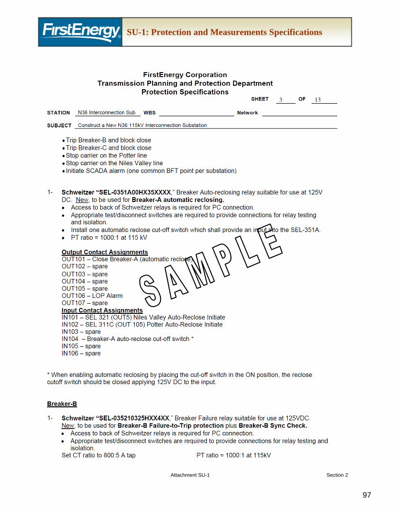
5.1 The TO’s Planning and Protection Group will provide the protection requirements (Attachment SU-1) for the TO interconnection substation. This will detail the equipment necessary for transmission line and substation protection including any communication devices necessary for protection coordination.
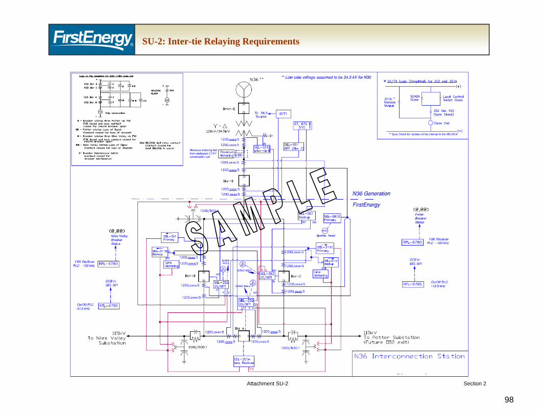
5.2 The TO will also provide the inter-tie relaying requirements (Attachment SU-2) to be installed in the Customer Interconnection Facilities and/or Customer Facility, as appropriate.
6. Communications Requirements
6.1 Please see “FirstEnergy Wholesale Generation Interconnection Customer Requirements – Communications” for detailed communications requirements.
7. Revenue Metering and Electric Service Billing Requirements
7.1 Please see “FirstEnergy Wholesale Generation Interconnection Customer Requirements – Revenue Metering and Electric Service Billing” for detailed revenue metering and billing requirements.
8. Transmission Line Connection Requirements
8.1 Please see “FirstEnergy Wholesale Generation Interconnection Customer Requirements – Transmission Line” for detailed transmission line requirements.
9. Relay Settings
9.1 The TO will provide the relay settings for the TO Interconnection Facilities.
9.2 The TO will provide the relay settings for the Inter-tie relay at the Customer Interconnection Facilities and/or Customer Facility, as appropriate.
10. Testing & Commissioning Requirements
10.1 The TO will provide testing and commissioning requirements.
10.2 Please note: The TO will not commence with a transmission system outage to connect the new TO Interconnection Facilities until communication circuits are operational and all off-line testing and commissioning is complete. All functional testing of the controls are to be witnessed by the TO Commissioning Engineer.
11. Substation Construction Requirements
11.1 IC is required to select a construction contractor from the FE approved contractor list that is located on the PJM website. This approved contractor will construct all interconnection facilities in accordance with FE construction standards and testing requirements.
12. Outage Scheduling
12.1 Please see “FirstEnergy Wholesale Generation Interconnection Customer Requirements – Agreements Support” for detailed outage scheduling requirements.
C. FE WGI Required Documentation
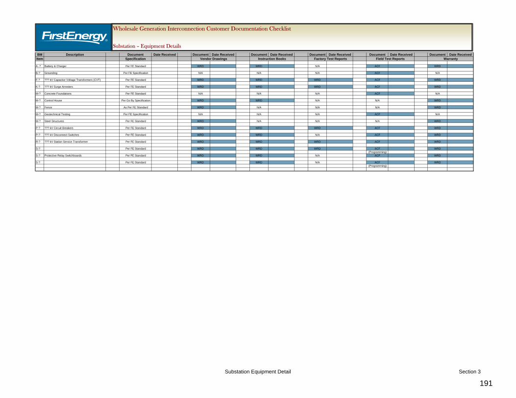
1. The IC shall provide the following documents to the TO for review and acceptance. IC is required to coordinate with the TO’s A/E project management to determine the appropriate document format. Following the TO’s review, the IC shall incorporate all of the TO’s review comments and resubmit the documents as necessary until the TO’s acceptance is granted.
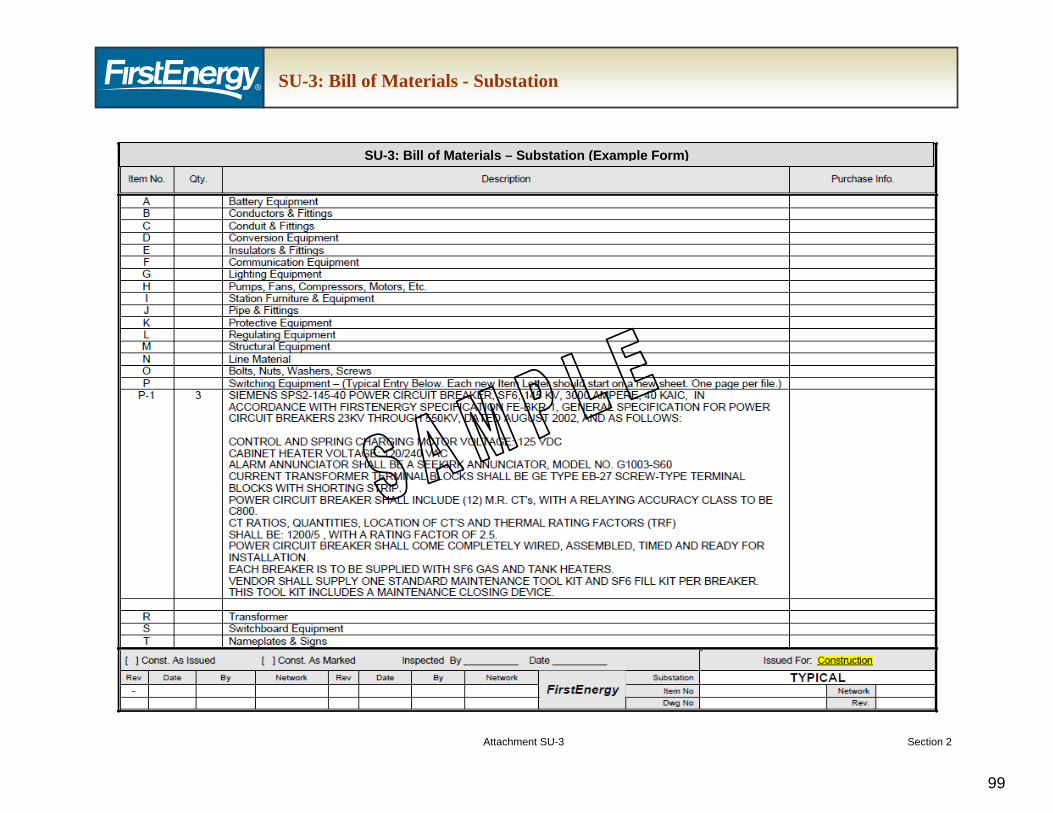
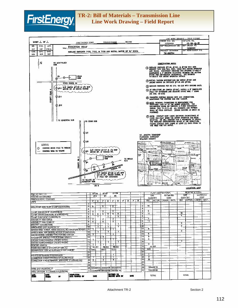
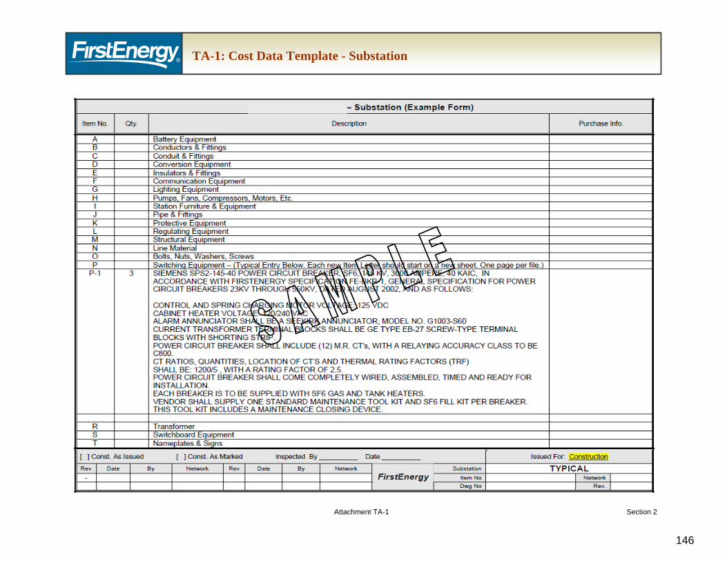
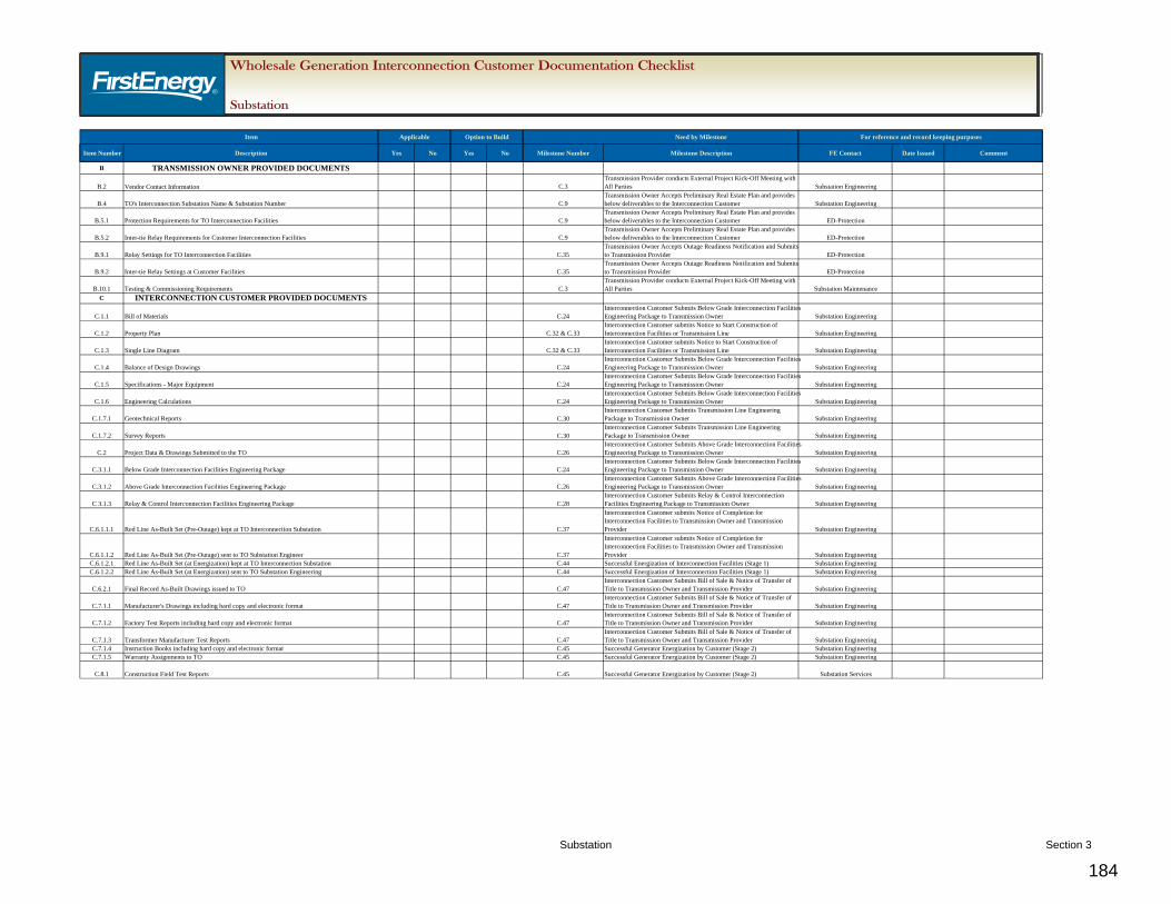
1.1. Bill of Materials (BOM) – The BOM (Attachment SU-3) shall include everything that is purchased and installed for the TO Interconnection Facilities (listed per major equipment and material).
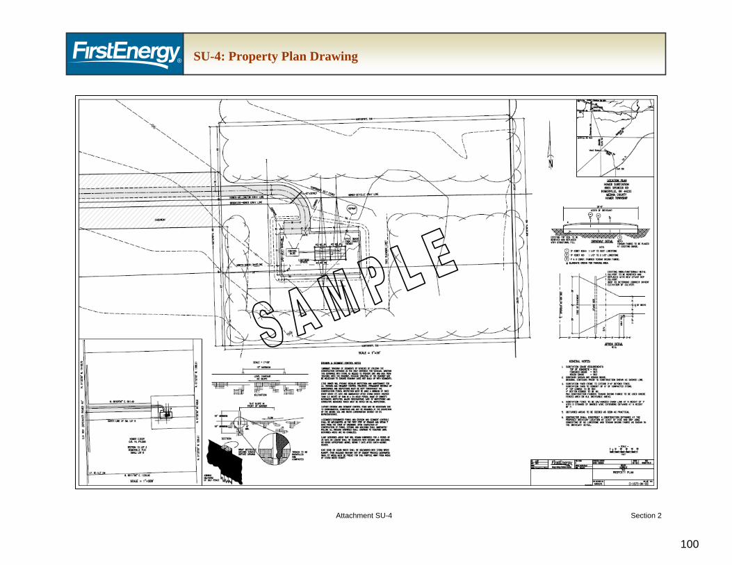
1.2. Property Plan - A property plan (Attachment SU-4) shall be developed detailing the location, and fee ownership or perpetual easement property descriptions of the property to be conveyed to the TO. This drawing shall include as a minimum:
1.2.1. The legal description of the property owned or on which the easement is provided as well as any other easements relating to the transmission/distribution lines, access road or substation related construction. Please see “FirstEnergy Wholesale Generation Interconnection Customer Requirements – Real Estate” for detailed property requirements.
1.2.2. The driveway shown to the road intersection.
1.2.3. Driveway gate, if any, and driveway entrance apron.
1.2.4. Names of adjoining property owners.
1.2.5. Contour lines and substation final grade elevations.
1.2.6. Substation fence showing gate location.
1.2.7. Fence details, by description or detail view.
1.2.8. A simplified plan view of the substation equipment.
1.2.9. Landscaping, if any (must all be compatible species)
1.2.9.1. Limited space for tree and shrub growth, both above and below ground, restricts choices among species at many planting sites. For locations with overhead electric lines, species should be selected that will not interfere with wires. In narrow spaces between sidewalks and curbs, the most suitable trees and shrubs have smaller crowns and root systems less likely to lift pavements or interfere with structures. There are other kind of space constraints, as well as landscape design considerations (e.g. screens), that call for trees and shrubs in small stature, i.e., trees and or shrubs with mature heights at or below 10 ft.
1.2.10. Substation yard surface details, by description or detail view.
1.2.11. Notes with construction details.
1.2.12. A key (location) map.
1.2.13. Basic drawing features - title block, north arrow, legend, graphic scale.
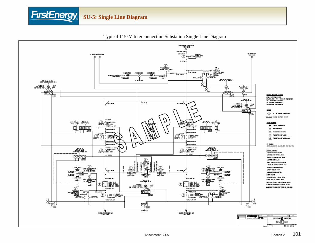
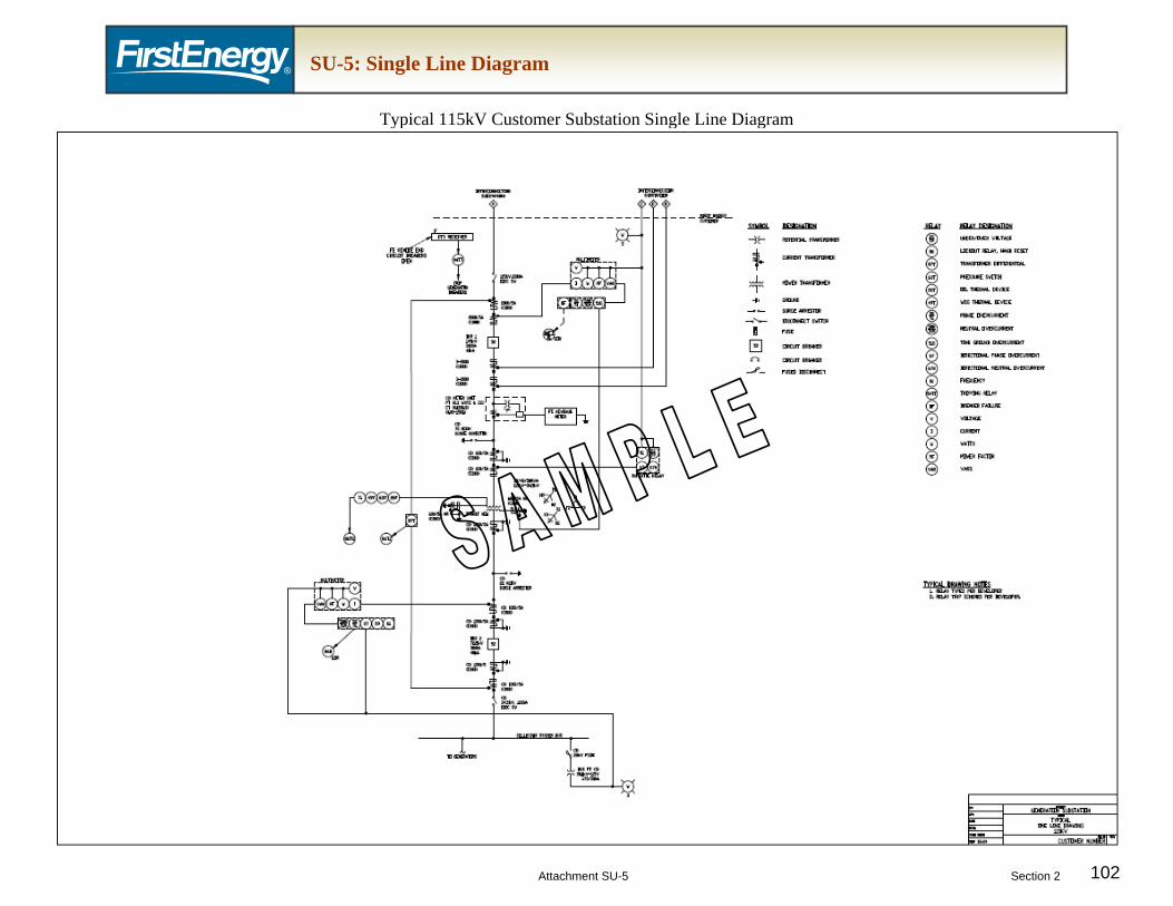
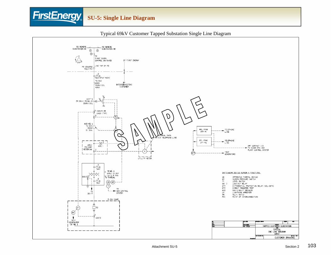
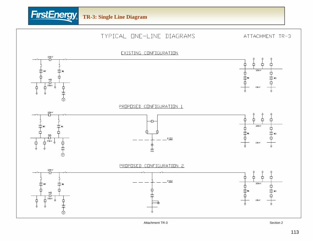
1.3. Single Line Diagram – The single line diagram has been listed separately due to its extensive use by many functions of the TO. It is usually one of the first drawings to be developed, reviewed, and accepted and should contain the necessary detail for both the TO Interconnection Facilities and the IC Interconnection Facilities, including revenue metering location. (Attachment SU-5).
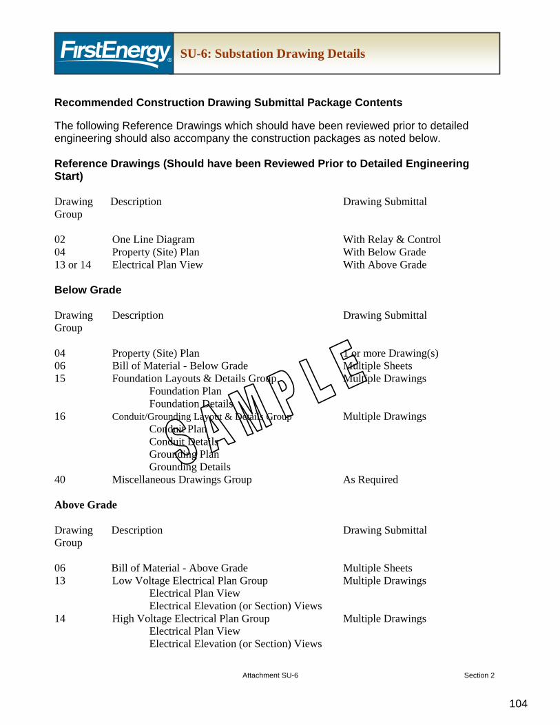
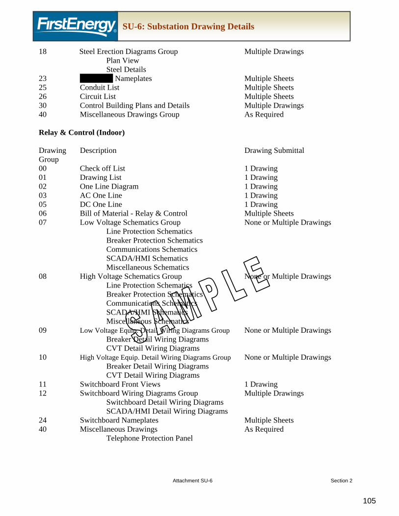
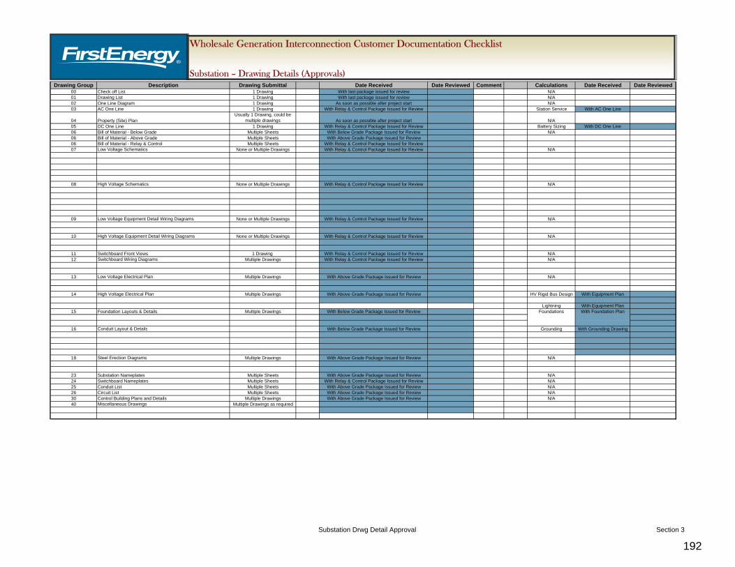
1.4. Balance of Design Drawings – Please see Attachment SU-6 for further substation drawing details. All design drawings must be reviewed and accepted by the TO and the TP and shall include, but not be limited to, the following:
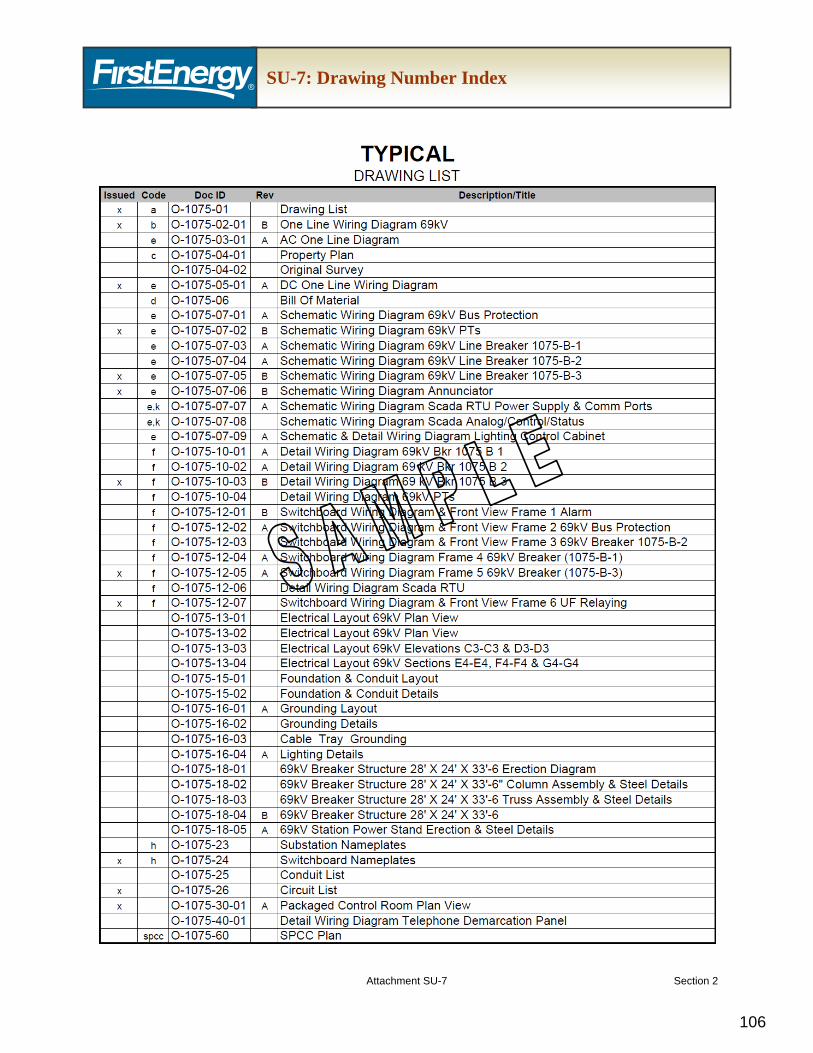
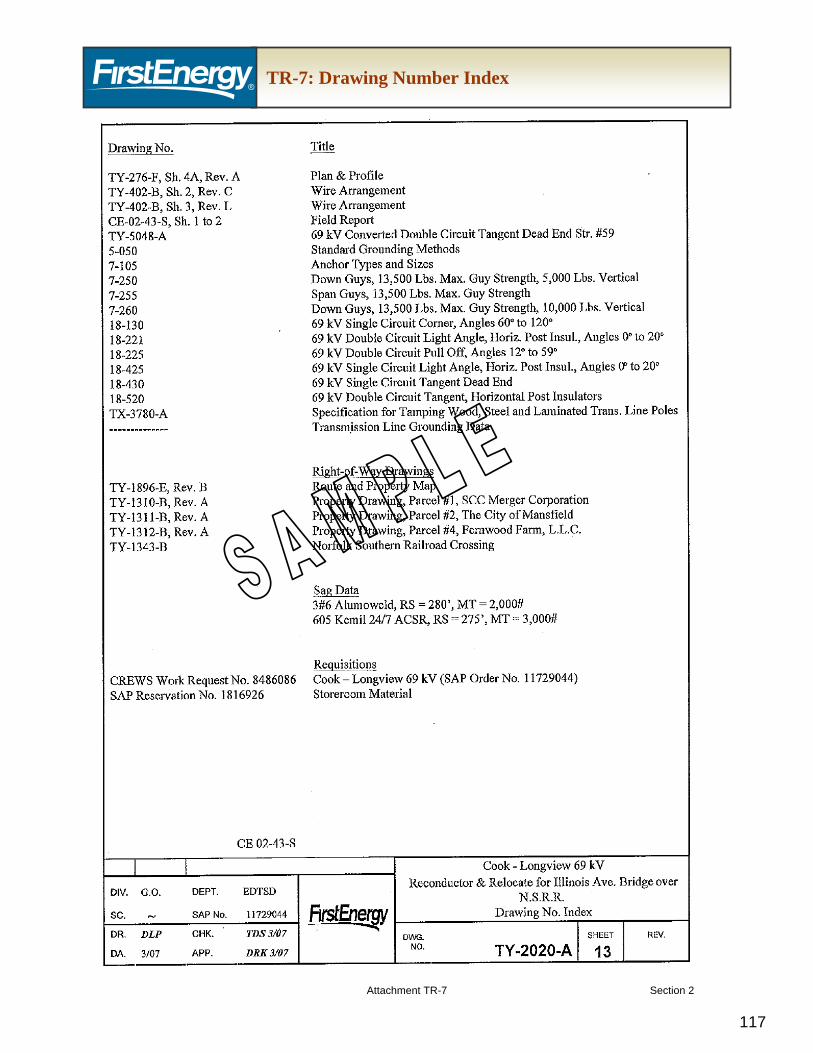
1.4.1. Drawing number index (See Attachment SU-7 for example)
1.4.2. List of all drawings used
1.4.3. Structure drawings
1.4.4. Use FE standard drawings (coordinate with the TO if standard drawings cannot be used
1.5. Specifications (Major Equipment) – Any equipment that is purchased that requires a unique specification shall be sent to the TO for review and acceptance.
1.6. Engineering Calculations – The following design calculations shall be submitted for the TO’s review and acceptance:
1.6.7. Transformer Sound Level Calculations in accordance with NEMA Standards
1.7. Design Field Testing and Data Collection
1.7.1. Geotechnical Reports
1.7.2. Survey Reports
Please Note: Wetland delineations, stream evaluations and similar ecological field studies and reports may be required. Please see “FirstEnergy Wholesale Generation Interconnection Customer Requirements – Regulatory Siting and Environmental Permitting” for detailed environmental requirements.
2. Project Data & Drawings Submitted to the TO:
2.1. A single line diagram of the project that includes all transmission line and Interconnection Facilities to be installed (see Section 1.3 above).
2.2. The Generator Electrical System Single Line Diagram (Interconnection Customer Facility)
2.3. Actual Generator Electrical System Design Information (So a computer model can be made of the system) to include as a minimum:
2.3.1. Transformer Design Information
2.3.1.1. Nameplate
2.3.1.2. Impedance Data
2.3.1.3. Test Report
2.3.2. Generator Design Information
2.3.2.1. Impedance Data
2.3.2.2. Transmission Line Electrical Design Information
2.3.2.3. Line Impedances - Positive & Zero Sequence
2.3.2.4. Line Length
2.3.2.5. Conductor Data
2.3.3. Generation Electrical System Data
2.3.3.1. Short Circuit Equivalent Impedances
2.4. Common Relay System Design Data
2.4.1. Example - Current Transformer Lead Lengths for Bus Differential Relaying Circuits
2.4.2. Current Transformer Excitation Curves
2.5. Generator Electrical System Drawings
2.5.1. AC & DC Schematics for the Main Breaker, and Transformer Protection
2.5.3.1. Relay Settings for Developer provided relays that need to coordinate with the TO’s Interconnection Substation Relays.
3. Drawings Issued for Construction
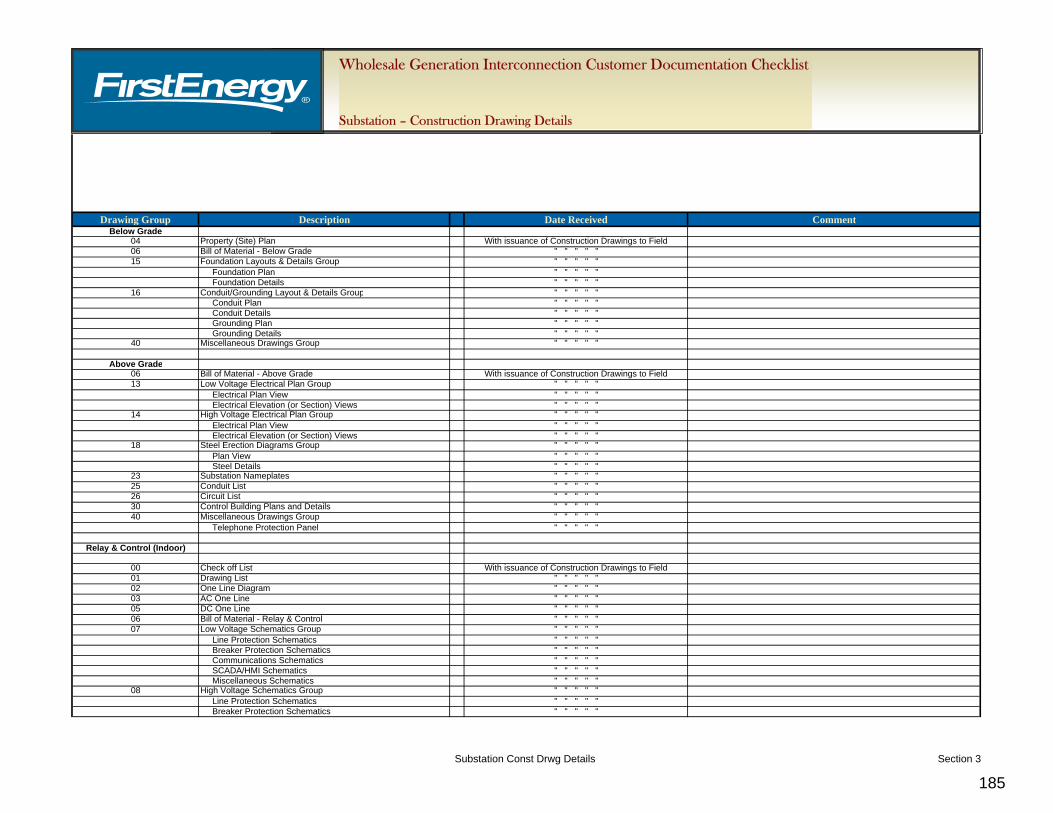
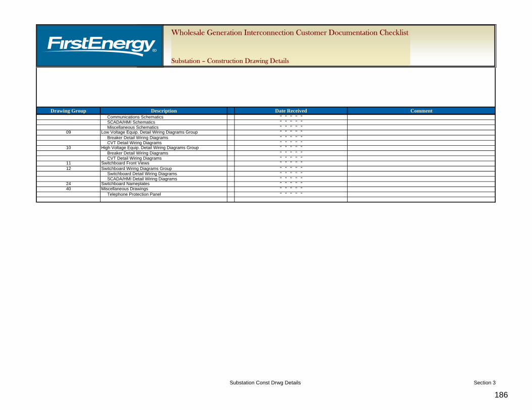
3.1. The IC will provide hard copies of the construction drawings per a distribution list provided by the TO. The details of the “Issued for Construction Drawings” shall be recorded on the “FirstEnergy Wholesale Generation Interconnection Customer Substation Required Documentation Checklist - Construction Drawing Details.” There are three Milestones that coincide with the issuance of the Below Grade, Above Grade and Relay & Control Engineering packages:
3.1.1. Milestone C.24 - IC Submits Below Grade Interconnection Facilities Engineering Package to TO
3.1.2. Milestone C.26 - IC Submits Above Grade Interconnection Facilities Engineering Package to TO
3.1.3. Milestone C.28 - IC Submits Relay & Control Interconnection Facilities Engineering Package to TO
Note: Please see Attachment SU-6 for the construction drawing package submittals. The distribution shall be made according to the FirstEnergy Print Distribution List that is available to the TO’s approved Engineering Contractor.
4. Field Engineer/Inspector
4.1. Please see “FirstEnergy Wholesale Generation Interconnection Customer Requirements – Agreements Support” for detailed Field Engineer/Inspector requirements.
5. Project Change Request Process
5.1. Please see “FirstEnergy Wholesale Generation Interconnection Customer Requirements – Agreements Support” for detailed Project Change Request Process requirements.
6. As-Built Drawings – Red Line and Final Record
6.1. Red Line
6.1.1. At the end of construction for Milestone C.37 - “Interconnection Customer submits Notice of Completion for Interconnection Facilities to Transmission Owner and Transmission Provider” and prior to the scheduled Transmission line outage, the following red line as-built drawing set shall be provided:
6.1.1.1. One (1) current Red Line set remains in the TO interconnection substation for the TO’s field use.
6.1.1.2. One (1) current Red Line drawing will be submitted to the TO’s Substation Engineer for the TO’s review and acceptance. The IC shall incorporate all of the TO’s comments into the drawings and resubmit the drawings as necessary until accepted.
6.1.1.3. Please Note: IC is required to coordinate with the TO’s A/E project management to determine the appropriate drawing format.
6.1.2. At Milestone C.44 – “Successful Energization of Interconnection Facilities (Stage 1)”, the following sets of red line as-built drawings shall be provided:
6.1.2.1. One (1) current Red Line set remains in the TO interconnection substation for the TO’s field use
6.1.2.2. One (1) current set is sent to the TO’s Substation Engineer for interim use.
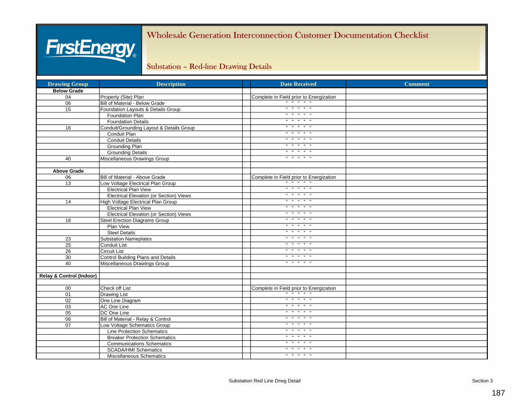
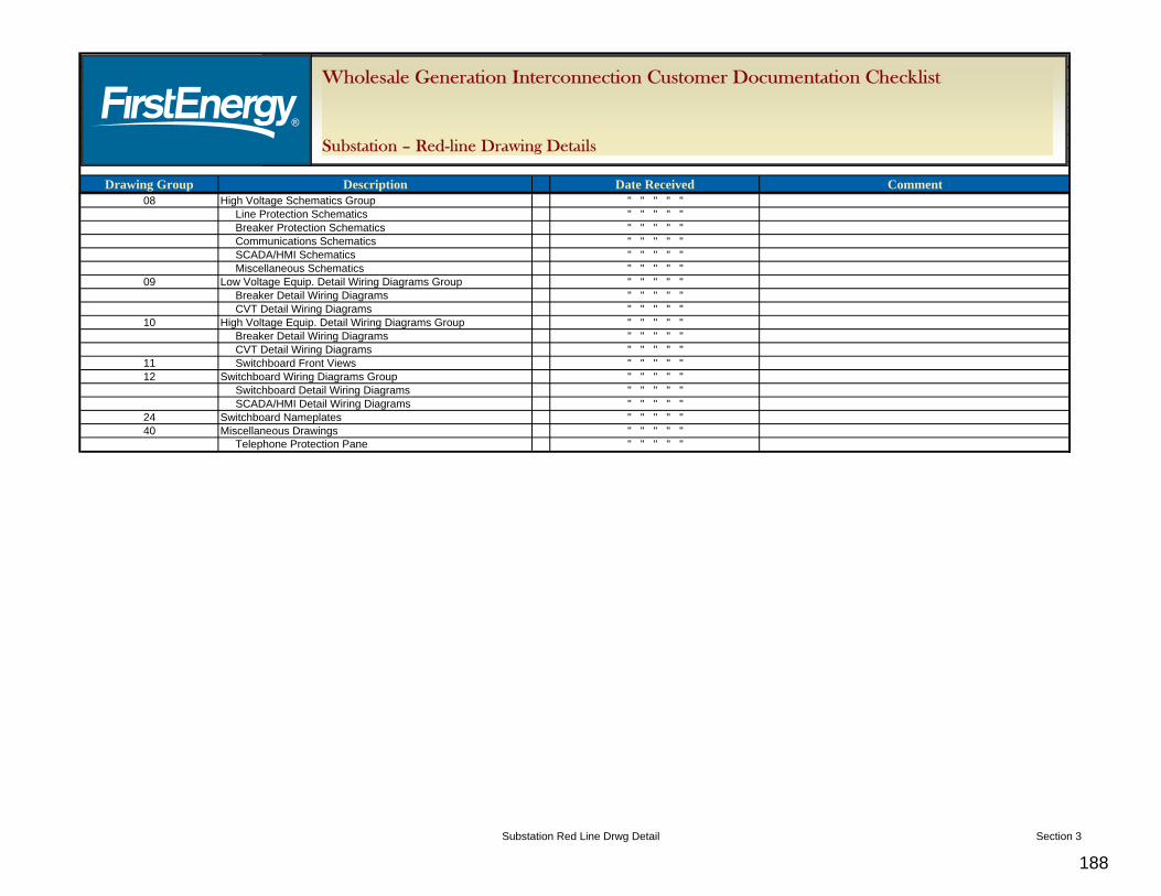
6.1.2.3. The details of the red line as-built drawings shall be recorded on the “FirstEnergy Wholesale Generation Interconnection Customer Substation Required Documentation Checklist - Red-Line Drawing Details.”
6.1.2.4. Please Note: Each unique change to the construction drawings conveyed in the red line as-built drawings must be directly linked to a TO reviewed and accepted field change. Please see “FirstEnergy Wholesale Generation Interconnection Customer Requirements – Agreements Support” for detailed field change requirements.
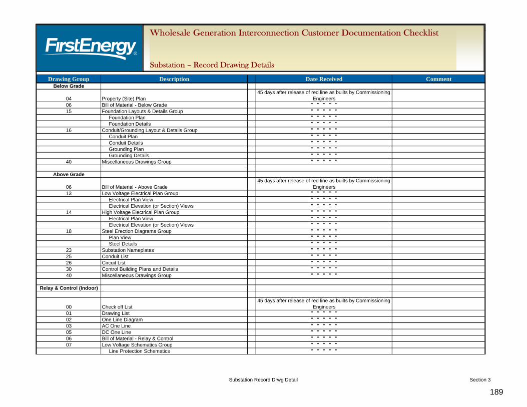
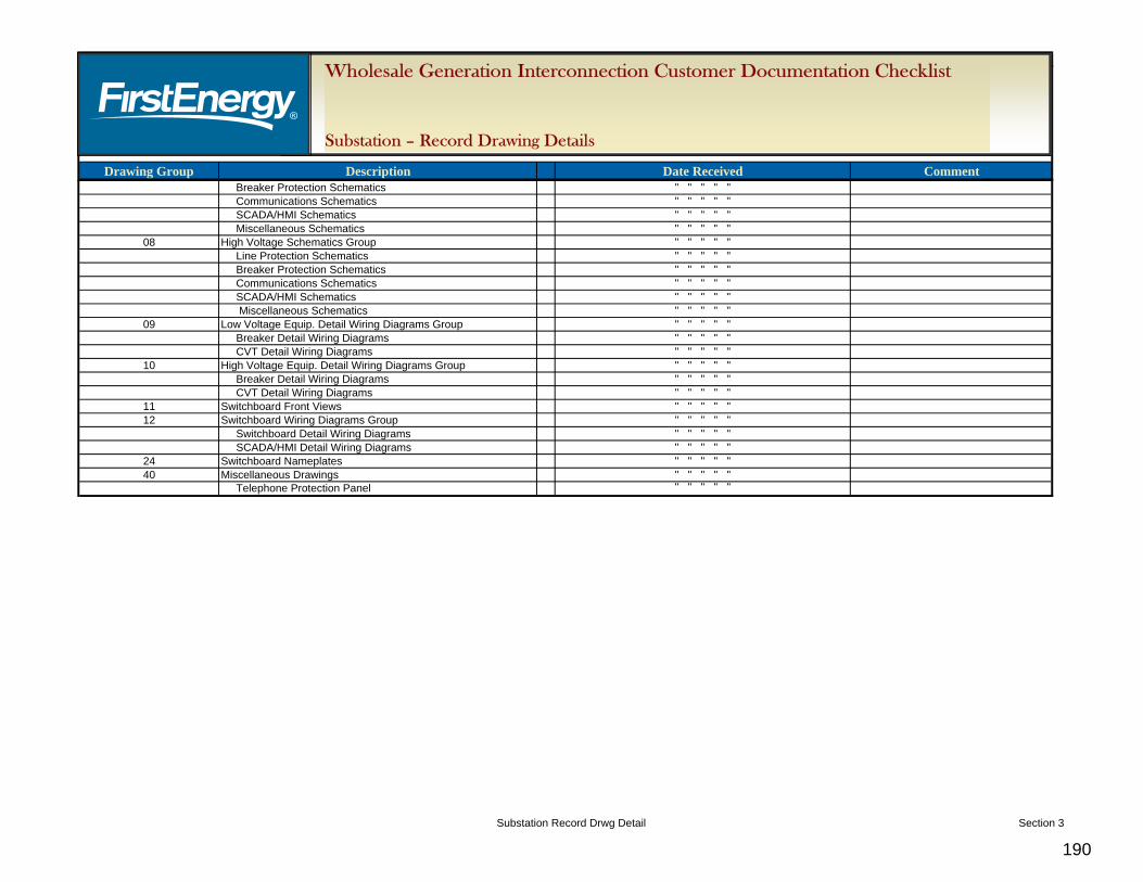
6.2. Final Record
6.2.1. The record as-built drawings shall be issued to the TO in electronic (AutoCAD) format within 45 days after initial operation. IC is required to coordinate with the TO’s A/E project management to determine the appropriate drawing format. The record as-built drawings must be submitted for Milestone C.47 – “Interconnection Customer Submits Bill of Sale & Notice of Transfer of Title to Transmission Owner and Transmission Provider”. It is expected that the Final Record Drawings will be complete and all red-line changes have been incorporated. The details of the Final Record as-built drawings shall be recorded on the “FirstEnergy Wholesale Generation Interconnection Customer Substation Required Documentation Checklist - Record Drawing Details.”
7. Manufacturer Drawings
7.1. The manufacturer drawings shall be issued to the TO in electronic (AutoCAD) format within 45 days after energization. IC is required to coordinate with the TO’s A/E project management to determine the appropriate drawing format. The IC shall provide the following documentation per the print distribution list (see the Note following Section 3.1.3):
7.1.1. Manufacturer drawings include hard copies and AutoCAD files (As described previously, these drawings must be included as part of the structure drawings submitted for the TO’s review and acceptance)
7.1.2. Factory test reports include hard copies and pdf files (As described previously, the factory test reports must also be submitted for the TO’s review and acceptance)
7.1.3. Transformer Manufacturer Test Reports to include Loss Tests, Thermal Tests, Dielectric Tests, Oil Certification, Ratio Test, Power Factor Test, Insulation Resistance Tests, and Sound Tests
7.1.4. Instruction books include hard copies and pdf files
7.1.5. Warranty assignments to be provided to the TO
7.1.5.1. Any material or equipment to be turned over to the TO shall also have the warranty transferred to the TO as the ultimate owner
7.1.5.2. Please note: It is required that the purchaser of the equipment ensure that the TO is identified, along with the substation name, on the purchase order as the ultimate owner no later than Milestone C.47 – “Interconnection Customer Submits Bill of Sale & Notice of Transfer of Title to Transmission Owner and Transmission Provider”.
8.1. The construction field test reports shall be issued to the TO within 45 days after energization. IC is required to coordinate with the TO’s A/E project management to determine the appropriate document format. Provide copies of all field test reports in hard copy and electronic format (pdf), as well as copies in the original test (equipment) format; e.g., power factor/timing/etc., per the print distribution list.
1. This document contains the Transmission Owner (TO) requirements for wholesale generation
interconnection projects consistent with the interconnection process as defined in the PJM Open Access Transmission Tariff (OATT) and applicable PJM manuals. The purpose of this document and attached checklist is to provide a detailed list of FirstEnergy (FE) requirements, including required documentation for operational and property transfer, if applicable, when a generation interconnection is requested by an Interconnection Customer (IC). These requirements will facilitate the safe, efficient and reliable integration of the Interconnection Facilities into the transmission system.
2. The “Wholesale Generation Interconnection Customer Transmission Documentation Checklist” will be used to track the status of each document.
B. FE WGI Requirements
1. The proposed Interconnection Facilities must be designed in accordance with the FE
“Requirements for Transmission Connected Facilities” located at http://www.firstenergycorp.com/feconnect/Requirements_for_Transmission_ Connected_Facilities.html
2. Transmission Line Design Requirements
2.1. IC is required to select a design contractor from the FE approved contractor list that is located on the PJM website. This approved contractor will design all interconnection facilities in accordance with the TO’s design standards. Refer to section B.1. for the FE standards and http://www.pjm.com for PJM standards.
3. Vendor Contact Information
3.1. The TO will provide the vendor contact information for major equipment to ensure the IC purchases equipment in accordance with FE standards. Refer to section B.1. for the FE standards and http://www.pjm.com for PJM standards.
4. TO’s Interconnection Transmission Line Identification
4.1. The TO will determine a suitable transmission line name and transmission line number for the TO interconnection transmission line once the location has been determined.
4.2. As applicable, the TO will determine a suitable number for the transmission poles being installed by the IC.
4.3. As applicable, the TO will determine a suitable number for the transmission switches and similar equipment being installed by the IC.
5. Communications Requirements
5.1. Please see “FirstEnergy Wholesale Generation Interconnection Customer Requirements – Communications” for detailed communications requirements and Attachment TR-1.
6. Transmission Line Connection Requirements
6.1. The TO will provide design details for the connection requirements to the existing TO transmission line. This includes, but is not limited to, dead end termination height, standard structure details and requirements, conductor type and size, static wire type and size, standard insulator and hardware, range of typical tension of the phase and
shield wires, grounding requirements, features of transmission switch and similar equipment and requirements.
7. Transmission Line Construction Requirements
7.1. IC is required to select a construction contractor from the FE approved contractor list that is located on the PJM website. This approved contractor will construct all interconnection facilities in accordance with FE construction standards.
8. Transmission Line Standard Material Requirements
8.1. The TO will provide standard material requirements for design and the construction of the transmission line. This includes, but is not limited to, wire size and manufacturer; hardware size, type and manufacturer; insulator size, type and manufacturer; pole type, size and manufacturer; guying size, type and manufacturer; transmission switch and similar equipment type, size and manufacturer.
9. Transmission Line Right-of-Way Requirements
9.1. The TO will provide the minimal right-of-way width, danger tree requirements and associated requirements for the transmission line being installed by the IC based on the voltage, span length, structure type and other pertinent considerations.
9.2. Please note: The TO requires fee ownership interest or a perpetual easement for all right-of-ways. Please see “FirstEnergy Wholesale Generation Interconnection Customer Requirements – Real Estate” for detailed property requirements.
10. Testing & Commissioning Requirements
10.1. The TO will provide testing and commissioning requirements.
10.2. The TO will perform an Audit of the Facilities during Pre-energization
10.3. Please note: The TO will not commence with a transmission system outage to connect the new TO’s interconnection transmission line until communication circuits are operational and all off-line testing and commissioning is complete.
All functional testing of the controls are to be witnessed by the TO commissioning engineer.
11. Outage Scheduling
11.1. Please see “FirstEnergy Wholesale Generation Interconnection Customer Requirements – Agreements Support” for detailed outage scheduling requirements.
C. FE WGI Required Documentation
1. IC to provide the TO with the following documents:
1.1. The IC shall provide the following documents to the TO for the TO’s review and acceptance. IC is required to coordinate with the TO’s Transmission Design project management to determine the appropriate document format.
Please Note: The IC is responsible for the design of the transmission facilities in compliance with all applicable regulatory and code requirements. The IC shall submit all drawings to the TO for the TO’s review and acceptance prior to starting construction. The IC shall incorporate all TO comments into their engineering design and drawing efforts and resubmit the drawings as necessary until accepted by the TO.
1.1.1.3. Please Note: Wetland delineations, stream evaluations and similar ecological field studies and reports may be required. Please see “FirstEnergy Wholesale Generation Interconnection Customer Requirements – Regulatory Siting and Environmental Permitting” for detailed environmental requirements.
1.1.2. Bill of Materials (BOM) (Attachment TR-2)
1.1.2.1. The BOM shall include everything that is purchased and installed for the TO’s transmission line (listed per each structure).
1.1.3. Field Report (FR) (Attachment TR-2)
1.1.3.1. The FR provides installation information about the transmission line and shall include everything that is purchased and installed for the TO’s transmission line (listed per each structure).
1.1.3.2. Please note: In addition to being a reference for the TO’s transmission line construction drawings, the FR is also used as a basis by the TO accounting staff to accurately determine the value of the TO’s transmission line.
1.1.4. Single Line Diagram (Attachment TR-3)
1.1.4.1. This drawing shall contain the necessary existing Transmission Facilities and any new proposed Transmission Facilities required as part of interconnecting the Interconnection Facilities. This has been listed separately due to its extensive use by many functions of the TO. It is usually one of the first drawings to be developed, reviewed and accepted.
1.1.5. Plan and Profile Drawing(s) (Attachment TR-4)
1.1.5.1. Plan view shall include as a minimum an aerial image with streets, railroads, properties, counties, townships, municipalities identified, route right of way alignment and pole locations.
1.1.5.2. Profile view shall include as a minimum the structure number, structure type, pole size and class, structure drawing number, station, line angle, guying information, conductor and ground wire data (sag chart number, ruling span, maximum tension), and centerline ground elevations and offsets for steeply sloped locations.
1.1.5.3. Modifications to the existing Transmission line shall be made on the existing plan – Profile drawings.
1.1.5.4. New Plan – Profile drawings shall be provided in AutoCAD/PLS CAD drawing format as agreed to by Transmission Engineering.
1.1.6. Structure Drawings - These types of drawings shall be provided when using steel poles, lattice towers, laminated wood poles or similar structures, which are not depicted within FE’s Construction Standards. At a minimum the submittal is to include:
1.1.6.1. Plan view and elevation view of the structure, showing dimensions, material specifications, connection and manufacturing details, and total weight.
1.1.6.2. Foundation details and materials.
1.1.6.3. Shipping, handling and installation details as necessary.
1.1.6.4. Loading trees and similar engineering design information.
1.1.6.5. Fabrication drawings Transmission Line Section 1
1.1.6.7. Manufacturer drawings – these types of drawings shall be incorporated into and included as structure drawings.
1.1.6.8. Please note: The preference is to use FE’s Construction Standard Drawings. The requirements provided above are to be used whenever other installation details must be employed.
1.1.7. Wire Arrangement (Attachment TR-5) - A wire arrangement or “phasing” drawing shall be prepared. This drawing shall include as a minimum:
1.1.10.5. To be submitted Railroad crossing permit applications and all other related submittals
1.1.10.6. Approved Railroad crossing permits
1.1.10.7. River crossing drawings (Likely under US Army Corps of Engineers jurisdiction)
1.1.10.8. To be submitted River crossing permit applications and all other related submittals
1.1.10.9. Approved River crossing permits
1.1.10.10. FAA required drawings
1.1.10.11. To be submitted FAA required permit applications and all other related submittals
1.1.10.12. Approved FAA permits
1.1.10.13. Please note: The approved permits for all permits required for construction of the project are to be submitted to the TO prior to starting construction. Please see “FirstEnergy Wholesale Generation Interconnection Customer Requirements – Regulatory Siting and Environmental Permitting” for detailed permitting requirements.
1.1.11. Specifications – Major Equipment – shall include, but is not limited to:
1.1.11.1. Any significant equipment, and specifically equipment or material purchased that requires a unique specification or engineering drawings, shall be sent to FE for review and acceptance.
1.1.12. Engineering Calculations – shall include, but are not limited to:
1.1.12.1. Structure loading (tower steel or laminated pole load trees)
1.1.12.2. Foundations
1.1.12.3. Guying and anchors
1.1.12.4. Insulator swing
1.1.12.5. Galloping and Aeolian vibration
1.1.12.6. Uplift
1.1.12.7. Inductive considerations/coordination for railroad track signal lines and underground pipelines
1.1.13. Manufacturer Drawings – shall include, but are not limited to:
1.1.13.1. Manufacturer drawings
1.1.13.2. Factory test reports
1.2. Drawings Issued for Construction – shall include, but are not limited to:
1.2.11. Please Note: The IC will provide multiple sets of hard (paper) copies of the construction drawings per a distribution list provided by the TO. The details of the “Drawings Issued for Construction” shall be recorded on the “Wholesale Generation Interconnection Customer Transmission Line Documentation Checklist”.
1.3. GPS Locations of Transmission Line Structures
1.3.1. The IC shall provide GPS locations, accurate to one meter or less, of all installed transmission line structures. At a minimum, the pole numbers, approximate location and GPS locations are to be provided to the TO in a spreadsheet format, and the GPS locations are to be added to the drawings in the red line as-built drawing process.
1.4. Field Engineer/Inspector
1.4.1. Please see “FirstEnergy Wholesale Generation Interconnection Customer Requirements – Agreements Support” for detailed Field Engineer/Inspector requirements.
1.5. Project Change Request Process
1.5.1. Please see “FirstEnergy Wholesale Generation Interconnection Customer Requirements – Agreements Support” for detailed Project Change Request Process requirements
1.6. Red Line As-Built Drawings
1.6.1. At the end of construction and prior to the transmission outage, the IC shall provide to the TO the following sets of red line as-built drawings:
1.6.1.1. The Red Line drawings will be submitted to the TO’s Transmission Engineer for the TO’s review and acceptance. IC is required to coordinate with the TO’s Transmission Design project management to determine the appropriate drawing format. The IC shall incorporate all of the TO’s comments into the drawings and resubmit the drawings as necessary until accepted.
1.6.1.2. Please Note: Each unique change to the construction drawings conveyed in the red line as-built drawings must be directly linked to a TO reviewed and accepted field change. Please see “FirstEnergy Wholesale Generation Interconnection Customer Requirements – Agreements Support” for detailed field change requirements.
1.6.2. After Energization of the Interconnection Facilities, the following sets of red line as-built drawings shall be provided:
1.6.2.1. One (1) set, sent to the TO’s Transmission Engineer for interim use.
1.7. Final Record As-Built Drawings:
1.7.1. The IC shall provide to the TO record as-built drawings in electronic (AutoCAD) format within 45 days after initial operation. (There may be adjustments to the red line drawings after the transmission line is
energized. IC is required to coordinate with the TO’s Transmission Design project management to determine the appropriate drawing format.
1.8. Manufacturer Drawings - The IC shall provide the following documentation per the TO’s print distribution list within 45 days after energization:
1.8.1. Manufacturer drawings include hard copies and AutoCAD files. (As described previously, these drawings must be included as part of the structure drawings submitted for the TO’s review and acceptance). IC is required to coordinate with the TO’s Transmission Design project management to determine the appropriate drawing format.
1.8.2. Factory test reports include hard copies and pdf files. (As described previously, the factory test reports must also be submitted for the TO’s review and acceptance.)
1.8.3. Instruction books include hard copies and pdf files
1.8.4. Warranty assignments to be provided to the TO
1.8.4.1. Any material or equipment to be turned over to the TO shall also have the warranty transferred to the TO as the ultimate owner.
1.8.4.2. Please note: It is required that the purchaser of the equipment document that the TO is acknowledged along with the transmission line name, switch number or similar identifier, on the purchase order as the ultimate owner no later than Milestone C.47 – “Interconnection Customer Submits Bill of Sale and Notice of Transfer of Title to Transmission Owner and Transmission Provider.”
1.9. Construction Field Test Reports - The construction field test reports shall be issued to the TO within 45 days after energization. IC is required to coordinate with the TO’s Transmission Design project management to determine the appropriate document format.
1.9.1. Provide line grounding readings at each structure. (See Attachment TR-8 and TR-9 for standard grounding methods and transmission line grounding data).
1.9.2. Provide concrete test cylinder reports that contain a minimum of four test cylinders for each truck load of delivered concrete.
Communications A. Scope 1. This document contains the Transmission Owner (TO) requirements for wholesale generation
interconnection projects consistent with the interconnection process as defined in the PJM Open Access Transmission Tariff (OATT) and applicable PJM manuals. The purpose of this document and attached checklist is to provide a detailed list of FirstEnergy (FE) requirements, including required documentation for operational and property transfer, if applicable, when a generation interconnection is requested by an Interconnection Customer (IC). These requirements will facilitate the safe, efficient and reliable integration of the Interconnection Facilities into the transmission system.
2. The “Wholesale Generation Interconnection Customer Communication Documentation Checklist” will be used to track the status of each document.
B. FE WGI Requirements
1. TO Communications Design and Construction Involvement
1.1. It is imperative that the TO Network Engineering personnel are included early in the project discussion process, as specific communications requirements can vary depending upon the nature of the facility to be constructed.
1.2. TO Network Engineering will determine the quantity and type of communications circuits required, as well as the method of transport (metallic cable, fiber optics, etc). Communications facilities will be designed and built to these parameters.
2. The installation of communications circuits into electrical substations or facilities, where hazardous step potential voltages can occur due to ground potential rise (GPR) during fault conditions, requires specialized design practices. Communications infrastructure can be designed as either fiber optic cable or metallic cable, depending upon the specifics of the facility being constructed. Wherever feasible, the use of fiber optics is preferred. These designs are described as follows:
2.1. The use of fiber optics to provide electrical isolation has become a common and accepted alternative method. In this design, fiber optic cable is extended out from the substation, and the demarcation point with the local exchange carrier is established beyond the substation perimeter. Note that IC provision of GPR data is still required, as described in Section 2 above, in order to determine the safe distance for establishment of the demarcation point. The demarcation point is established in a pole or pad mounted outdoor enclosure specifically designed for this purpose. Specialized fiber optic electronics such as that manufactured by RLH Industries or Positron are used. In this application, the installation of fiber optic cable and electronics is typically the responsibility of the IC. Either single-mode or multi-mode fiber optic cable may be installed, depending upon the specifics of the application. Either SC or ST type fiber optic connectors may be used, depending upon the characteristics of the electronics installed. A primary advantage of this design is that it provides guaranteed electric isolation, as communications circuits are transported as light over glass. In addition, the establishment of the demarcation point beyond the substation perimeter allows for a “standard” installation from the local exchange carrier’s perspective. Circuits can be installed to the demarcation point earlier in the construction process so that they are available when needed by extension over the fiber optic cable, with the actual cable installation controlled by the IC.
2.2. Electrical isolation has traditionally been provided through the installation of high-dielectric metallic cable terminated on electronics such as that manufactured by Positron. In this application the cable is installed by the local exchange carrier, with
the design and overall length determined by the carrier based upon GPR data provided by the IC. Specific data requirements can vary by local exchange carrier. It is the IC’s responsibility to provide this information. Electronics can be provided either by the carrier or by the IC. It is essential that design and installation practices are followed to exacting standards in order to provide the isolation protection as required. Also note that since this is considered a “non-standard” installation by the local exchange carrier, excessively long lead times are common from placement of the circuit order to delivery of a working circuit. The IC has little control over this process, which can exceed six months in many cases.
2.3. RLH products have an unconditional lifetime warranty. Positron products come with a standard 5-year warranty. In either case, the TO will provide a detailed materials list once specifics of the installation are known.
3. TO Circuit Requirements (includes SCADA, Revenue Metering, Voice and Protective Relaying)
3.1. General Information - In most applications, the TO requires the IC to order a 4-Wire Analog Data Circuit for SCADA communications and a standard business line for voice communications. These circuits will terminate in the TO’s control house. The IC will also require SCADA, voice and revenue metering circuits in their control house. The type of SCADA circuit required is dependant upon the type of Remote Terminal Unit (RTU) device installed by the IC. The revenue metering and voice circuits are typically standard business lines. In all cases, the IC will need to obtain a street address for the substation in order to fulfill Enhanced 911 (E911) requirements prior to placement of the circuit orders. The IC will also be required to provide GPR data by completing a High Voltage Protection data form provided the serving telephone company.
3.2. Detail on the TO circuit requirements is provided below in order to assist the CI in placing the circuit orders:
3.2.1. SCADA Circuit – The TO currently requires a 4-Wire Analog Data Circuit (commonly referred to as an “FDDA” type circuit) for interface between the RTU and the regional control center. The IC should specify transmission levels of 0dB Transmit, 16dB Receive, with a line-powered Data Terminal Equipment (DTE) provided by the local exchange carrier. In fiber optic applications, the DTE must be able to provide access to tap points for sealing current to drive the optics at the demarcation point (specify Westell models 4368-02, 5496LGI2, 5497FA I3, or Verizon no. 934461).
3.2.2. Voice Circuit – A standard business line is ordered to support voice communications. The order should specify that the line is to be blocked from placing calls to area codes 900 and 976, and from 3rd party calling, collect and international calls.
3.2.3. Revenue Metering – A dedicated voice-grade analog telephone line is required to support remote access for the IC-owned revenue meter through a dial-up modem connection. This order should also specify that the line is to be blocked from placing calls to area codes 900 and 976, and from 3rd party calling, collect and international calls. The circuit and revenue meter are located in the IC’s step-up substation control house.
3.2.4. When required, protective relaying is supported by the installation of fiber optic cable between the IC’s substation and the transmission line tap point or the TO substation. Either single-mode or multi-mode fiber optic cable may be installed, depending upon the specifics of the application. Either SC or ST type fiber optic connectors may be used, depending upon the characteristics of the electronics installed.
3.2.5. Note that when placing circuit orders with the serving telephone company, a defined street address is required for E911 purposes. It is the IC’s responsibility to obtain this address.
4. RTU Requirements
4.1. The TO will provide a specification for the purchase of the RTU. If the substation will be owned by the TO, the standard TO RTU to use shall be the “GE D20” RTU. The typical RTU used at TO transmission stations is a factory assembled RTU, which includes an RTU (BASE) D20 VME chassis with one Analog, one Status, and one Control peripheral boards as well as 125VDC power supply, bell 202 modem in a NEMA 12 cabinet. This is subject to change; as the substation is engineered there may be a need to add/change the RTU equipment.
4.2. The RTU shall provide the TO with at least the information and control capabilities listed in this document. Facilities with unusual or non-conforming load characteristics may be required to provide additional information and control beyond those listed.
4.3. Control – The RTU shall provide the TO with control of all circuit interrupting devices that are directly in the TO transmission path.
4.4. Position indication – The RTU shall provide the TO position indication of all transmission voltage circuit interrupting devices and motor operated disconnect devices.
4.5. Alarms – The RTU shall provide the TO equipment alarm information for each circuit interrupting device and associated protective relaying in the transmission path. Indication of protective relay operation alarms for relaying other than the transmission line relaying that operates a circuit interrupting device in the transmission path will also be provided. (These may include breaker failure or bus differential relaying.)
4.6. Operational Metering – The RTU shall provide the TO instantaneous bi-directional real and reactive power metering (MW and MVAR) and voltage for all TO transmission lines connected to the facility, as well as ampere metering of each circuit breaker in the transmission path. These quantities may be measured using relay accuracy class instrument transformers and meters/transducers. For RTUs serially connected to Satec meters, an optically isolated RS-232 to RS-485 converter will be used. Equipment typically used is the B&B model :485LDRC9.
4.7. The TO will provide communication protocol for the RTU that may be located in the IC’s substation or Customer Facility, as appropriate. The protocol for the RTU will be “DNP 3.0” if communicating to the TO’s EMS (Energy Management System).
4.8. The TO will provide a typical points list for development of the TO’s Interconnection substation RTU and Human Machine Interface (HMI)/Annunciator. The points list may be modified; however, a final points list must be issued to a TO SCADA engineer and a TO substation design engineer for final review. The points list will be entered into the EMS database for upload into the system. EMS uploads occur once every two weeks. Ample time should be given to enter RTU information into an EMS database upload before a scheduled outage of the substation. RTU information should be in the EMS database one month prior to substation outage. This will allow for testing between the RTU and the EMS system and will allow for any changes that need to be made to the RTU or EMS database before the scheduled outage.
4.9. Testing – The RTU’s communication and most data points on the points list will be tested to the TO’s EMS system before the scheduled outage. It is understood that not all points will be able to be tested down to the field/equipment level until the outage has occurred.
4.10. The TO will provide the list of points required to be transmitted to the TO Transmission System Operator (TSO) from the IC’s substation or Customer Facility, as appropriate.
C. FE WGI Required Documentation 1. TO to provide the IC with the following documents:
1.1. Telecommunications Protection Design Standard (Attachment CO-1)
1.4. High Voltage Protection Form “Verizon Example”
(Attachment CO-4)
1.5. SCADA Points List – Example Form (Attachment CO-5)
1.6. Optical Power Measurement Form (Attachment CO-6)
1.7. TO Required Communication Materials and Equipment List (See Section B.2.2.3 for timing of issuance)
1.8. Network Standards Design - The TO uses either wireless or fiber optic technology for SCADA communications to line switches, depending upon the specific application. When wireless communications is deployed, this will be implemented internally by TO personnel on existing wireless platforms. If the use of fiber optics is selected, construction of fiber optic cable between the control house and the switch location will be required. (Attachment CO-7)
2. IC to provide the TO with the following documents:
2.1. E911 Address Confirmation - Provided in Outage Readiness Notification
2.2. Substation conduit detail design drawing
2.3. Substation control house rack layout drawing
2.4. Copies of Telco service orders, including projected due dates
2.5. Completed High Voltage Protection Form, including Telco provided calculations
2.6. SCADA/RTU Points List – completed form
2.7. Fiber optic cable power measurement test results
2.8. RTU Schematic
2.9. RTU/HMI Configuration Files
2.10. OTDR Traces test results
2.11. Communication Equipment Manufacturers Manuals and Warranty Information
2.12. Communication Equipment Spares List
2.13. Notification that RTU Communication Circuits are ready for TO Testing
2.14. Notification that RTU is ready for TO Testing
Revenue Metering and Electric Service Billing A. Scope
1. This document contains the Transmission Owner (TO) requirements for wholesale generation
interconnection projects consistent with the interconnection process as defined in the PJM Open Access Transmission Tariff (OATT) and applicable PJM manuals. The purpose of this document and attached checklist is to provide a detailed list of FirstEnergy (FE) requirements, including required documentation for operational and property transfer, if applicable, when a generation interconnection is requested by an Interconnection Customer (IC). These requirements will facilitate the safe, efficient and reliable integration of the Interconnection Facilities into the transmission system.
2. The “Wholesale Generation Interconnection Customer Revenue Metering and Electric Service Billing Documentation Checklist” will be used to track the status of each document.
B. FE WGI Requirements 1. Revenue Metering
1.1. The IC shall install, own, operate, test and maintain the necessary revenue quality Metering equipment. This includes current transformers, voltage transformers, mounting structures, wiring, meters, communication circuits and associated devices. The Metering equipment must meet the specifications listed in the TO and TP connection documents. The FE “Requirements for Transmission Connected Facilities” is located at: http://www.firstenergycorp.com/feconnect
1.2. The Metering equipment shall be located at the IC Facility on the high-voltage side of the generator step-up transformer(s) and/or station service power transformer(s). Power flows to and from the facility shall be compensated for line losses to the Point of Interconnection. Line loss compensation is not required if the IC’s step-up substation property adjoins the Interconnected TO’s substation property, which generally places the IC's Metering equipment at the Point of Interconnection.
1.3. The revenue quality Metering equipment shall be capable of collecting and storing bidirectional billing data. The billing data shall be stored in intervals specified by the TO, typically fifteen minutes or thirty minutes. The IC must provide the TO with remote access to the billing data in the Metering equipment via a dedicated voice-grade analog telephone circuit. The IC shall provide the TO with contact information for the person(s) responsible for meter programming and Metering equipment maintenance.
1.4. The IC shall provide the TO with prior notification of any modifications at the facility that will affect the revenue meter measurements, including substation reconfigurations and meter program changes.
1.5. The revenue metering system at each location shall be tested for accuracy by the IC once every two years. The IC shall give reasonable notice to the TO of the time when the testing is scheduled so that the TO may have representatives present. The TO and the TP shall have the right to audit the revenue Metering equipment and/or related documents. The IC shall be given a reasonable period of time to comply with any requests associated with an audit.
2. Electric Service Billing
2.1. The Station Power billing shall be for one (1) year and shall renew automatically from year to year until terminated by written notice from either party to the other at least thirty (30) days prior to the expiration of any of the Application For Service time periods.
2.2. In the event that PJM does not reallocate the IC’s capacity obligation back to the IC, the TO will bill the IC for all costs resulting from any future capacity obligations at PJM.
Revenue Metering and Electric Service Billing Section 1
2.3. Official written refusal of service is required from the local Electric Distribution Companies (EDC) (or Rural Electric Co-Op (REC) ) if the local EDC refuses to serve energy as specified above.
2.4. FERC and PUCO/PUC/BPU regulations both govern the billing of the IC’s power flow. FERC regulations govern billing for the IC’s generation output for both transmission and distribution interconnections. The PUCO/PUC/BPU regulations govern billing for retail and backup retail service for both transmission and distribution service customers. FE retail tariffs are available at www.firstenergycorp.com.
2.5. ICs require energy for uses in various forms.
2.5.1 Station service is typically a few hundred kVA to feed substation control power only, with no power leaving the sub.
2.5.2 Station power is actually flowing into the Interconnection facility for either backup service to allow for power backfeed into the Interconnection when power generation is very low or at zero either due to a trip or other normal event, or as maintenance power for use during a planned maintenance outage, usually for an extended period of time.
2.6. The various sources of power above might come from different sources, with different EDC, with different energy suppliers, and with different contracts.
2.7. If the Interconnection is in another EDC territory, but connects to FE transmission, then the local EDC has first right to substation control power, and backup and maintenance power if electrically feasible. Interconnections with a single electrical source for power other than the substation will realistically take power from the Point of Interconnection, requiring flow from the FE transmission system.
2.8. The TO shall furnish Station Power (as the term is defined by the PJM Interconnection, L.L.C. Open Access Transmission Tariff [“OATT”]) to the IC’s generation facility. Station Power service will be rendered by the TO consistent with PJM’s monthly netting methodology set forth in the PJM OATT, as said OATT may be modified from time to time.
2.9. The TP shall determine the IC’s gross energy output less the Station Power requirements of the IC (“Net Output”).
2.9.1 Net Positive – The TO will bill the Minimum Charge of the Applicable Rate Schedule at the then prevailing prices on a monthly basis, applicable to recover the TO’s costs associated with the ownership and maintenance of any metering and related equipment and administrative efforts for the provision of Station Power.
2.9.2 Net Negative – The TO will bill the IC for the energy and import flow at the charges set forth in the applicable Rate Schedule at the then-prevailing prices on a monthly basis with the exception of the Generation and Transmission Charges. The Generation Charge will be billed at the Real Time Locational Marginal Price for the FE Zone for the net energy, and the Transmission Charge will be billed for the net energy at the charges set forth in the appropriate Rate Schedule at the then prevailing prices on a monthly basis, unless the energy is purchased from a Third Party Supplier in which case the Generation and Transmission Charges will be provided by the Third Party Supplier.
2.10. The TO will provide the following applications:
2.10.1 Application for Electrical Service – General
2.10.2 Application for Station Power Service
2.10.3 Application and Agreement for Backup and Maintenance Service
Revenue Metering and Electric Service Billing Section 1
1. Revenue Metering—the IC shall consult with the TO regarding the revenue quality metering system design and provide the following information:
1.1. Single-line diagram showing revenue metering in the IC's step-up substation.
1.2. Estimated power flows to and from the IC's step-up substation at all revenue metering points.
1.3. Proposed revenue metering current transformer (CT) and voltage transformer (VT) specifications including manufacturer, type, ratios, accuracy ratings and burden ratings.
1.4. Proposed revenue meter specifications including manufacturer, type and model number.
1.5. Conductor type, length, resistance per phase and reactance per phase for the transmission line between the IC's step-up substation and the Point of Interconnection (if applicable).
1.6. Three-line schematic and wiring diagrams showing all CT and VT connections to revenue meters.
1.7. Manufacturer's certified accuracy test reports for the revenue meter, CTs and VTs.
1.8. Revenue meter program information including but not limited to loss compensation values (if applicable), billing data recorder channel assignments, recorder pulse weights (Ke) and read-only password for access to interval data by the TO billing data collection system (MV-90).
1.9. Revenue meter telephone number.
1.10. Notice that the revenue meter is receiving current and voltage inputs from the CTs and VTs and is ready for real-time communications through the dedicated voice grade analog telephone circuit.
2. Electric Service Billing
2.1. The IC shall complete an Application for Electric Service document (Attachment RM-1) when the IC is distribution-connected to establish billing parameters such as the name, address, contact person and billing terms.
2.1.1. Verification of the billing entity, address and contract information needs to take place prior to the IC submitting the Bill of Sale and Notice of Transfer of Title to the TO.
2.2. The IC shall complete an Application for Station Power Service document (Attachment RM-2) when the IC is transmission-connected so the TO can furnish Station Power to the IC’s generation facility to establish billing parameters such as the name, address, contact person and billing terms.
2.2.1. Verification of the billing entity, address and contract information needs to take place prior to the IC submitting the Bill of Sale and Notice of Transfer of Title to the TO.
2.3. The IC shall optionally request Backup and Maintenance power via a separate application (Attachment RM-3) to avoid additional minimum bills when energy consumption exceeds energy production. Written notice as outlined in RM-3 shall be required when Backup or Maintenance power is taken or planned.
Revenue Metering and Electric Service Billing Section 1
2.4. Written notice to [email protected] is required when the IC obtains generation and transmission from a third party. The supplier must adhere to the TO and PUC notification rules.
Revenue Metering and Electric Service Billing Section 1
1. This document contains the Transmission Owner (TO) requirements for wholesale generation interconnection projects consistent with the interconnection process as defined in the PJM Open Access Transmission Tariff (OATT) and applicable PJM manuals. The purpose of this document and attached checklist is to provide a detailed list of FirstEnergy (FE) requirements, including required documentation for operational and property transfer, if applicable, when a generation interconnection is requested by an Interconnection Customer (IC). These requirements will facilitate the safe, efficient and reliable integration of the Interconnection Facilities into the transmission system.
2. The “Wholesale Generation Interconnection Customer Tax and Accounting Documentation Checklist” will be used to track the status of each document.
B. FE WGI Requirements
1. Tax Requirements
1.1. A representation from an independent engineer that the facility will not exceed the 95/5 power flows test on a prospective basis, for the first ten taxable years of the Utility beginning with the year of asset ownership transfer. (Notice 88-129). Please see “FirstEnergy Wholesale Generation Interconnection Requirements – Agreements Support” for details and an example of the 95/5 Power Flow Certificate.
1.2. A representation on the part of the IC that the asset ownership transfer is being made to facilitate the transmission of power over a transmission grid for sale to a third party. To this end, title to power must pass to the third party (PJM) prior to the buss bar.
1.3. A representation that the asset ownership transfer is made in connection with a long-term interconnection agreement with a term of at least 10 years. (Notice 2001-82)
1.4. A representation on the part of the TO that the intertie is not included in the Utility's rate base. That is, the asset received from the customer will be added to the Continuous Property Record (CPR) at $0 net value. Note that the value of the substation will be maintained in the CPR for property tax purposes.
1.5. A representation, on the part of the TO, that the asset ownership transfer otherwise will be treated as a capital contribution under IRC §118(a).
1.6. An indemnity, from the IC to the TO, that holds the TO harmless from the tax consequences of the asset ownership transfer if the IRS should change its position on intertie asset ownership transfers or if a disqualifying event occurs such as violating the 95/5 power flows test on an actual basis. If the asset ownership transfer becomes taxable, Notice 90-60 provides that the fair value of the asset ownership transfer will be determined by depreciated replacement cost at the time of the disqualifying event.
2. Accounting Requirements
2.1. Cost data must be submitted to the TO in the level of detail described below:
2.1.1. IC to provide installed cost and quantity of all major assets, including poles, towers, insulators, switches, breakers, transformers, motor operators, conductor and ground wire, etc. Hardware assemblies and clamps are to
be included as a miscellaneous bucket. Copies of all purchase orders, receipts, etc.
2.1.2. Personal property cost data must be separate from real property cost data
2.1.3. Cost data must be divided by function and by year (substation, transmission or distribution)
2.1.4. Once divided, the cost data must be detailed out by retirement unit. (See Attachment TA-1 for the Cost Data Template for Substation and Attachment TA-2 for the Cost Data Template for the Transmission Line).
C. FE WGI Documentation Requirements
1. Tax
1.1. 95/5 Power Flow Certificate (Attachment TA-3)
2. Accounting
2.1. Cost Data
2.1.1. IC to provide the following cost data to the TO for review and acceptance:
2.1.1.1. Completed Cost Data Template with Estimated Cost Data
2.1.1.2. Updated Cost Data Template with Actual Cost Data
2.1.1.3. Final Cost Data Template with “as-built” Actual Cost
Tax and Accounting Section 1
56
Table of Contents Section 2
Wholesale Generation Interconnection Attachments
Section 2 Contents AS-1: Project Team Contact List AS-2: Project Change Request Form AS-3: Interconnection Customer Outage Readiness Notification AS-4: Notice of Completion AS-5: Notice of Successful Inspection and Testing of Facilities AS-6: Notice of Transfer of Operational Control AS-7: Notice of Acceptance of Facilities AS-8: Notice of Transfer of Title AS-9: Bill of Sale RE-1: Easement with Preferred /Alternate Site Plan Layout RE-2: Complex Layout when Multiple Parcels are Involved RE-3: Property Owner Provision Plan RE-4: Site Access Agreement RE-5: Assignment of Easement RE-6: General Warranty Deed IN-1: Certificate of Insurance EN-1: Wholesale Generation Interconnection Permit Plan SU-1: Protection and Measurements Specifications SU-2: Inter-tie Relaying Requirements SU-3: Bill of Materials - Substation SU-4: Property Plan Drawing SU-5: Single Line Diagram SU-6: Substation Drawing Details SU-7: Drawing Number Index TR-1: Network Standards Design TR-2: Bill of Materials – Transmission Line/Line Work Drawing-Field Report TR-3: Single Line Diagram TR-4: Plan and Profile Drawing TR-5: Wire Arrangement TR-6: Route and Property Maps TR-7: Drawing Number Index TR-8: Standard Grounding Methods TR-9: Transmission Line Grounding Data CO-1: Telecommunications Protection Design Standard CO-2: The Positron Design. CO-3: The RLH Design CO-4: High Voltage Protection Form CO-5: SCADA Points List CO-6: Optical Power Measurement Form CO-7: Network Standards Design RM-1: Application for Electric Service - General RM-2: Application for Station Power Service RM-3: Application for Backup and Maintenance Electric Service TA-1: Cost Data Template - Substation TA-2: Cost Data Template – Transmission Line TA-3: 95/5 Power Flow Certificate
AS-2: Project Change Request Form This form will be used to document a change to an accepted project. This form should hold a summary of the impact of the proposed change. Change Request Forms are completed for all changes that require Acceptance by the Transmission Owner (TO) Project Management. Project: TO Project WBS # Submitted by : TO Interconnection Customer (IC): Submitted by Name: Phone: Date: Description of Recommended Change: Reason / Benefit / Justification for Change: Impact on Scope / Schedule / Budget: Description of Accepted Resolution: TO Project Manager Acceptance of Resolution: Phone: Date: IC Acceptance of Resolution: Phone: Date: Impacted Stakeholders:
1. The Interconnection Customer (IC) will submit the Outage Readiness Notification to the
Transmission Owner (TO) designee(s) as listed in Attachment AS-11 of the Transmission Owner Facility Requirements document, no later than seven (7) months prior to the requested Outage Date.
2. The TO will review and upon acceptance will submit the Outage Request to the Transmission Provider (TP) for review, acceptance and scheduling of the outage(s) necessary to construct and energize a new and/or rebuilt Transmission Line(s) and/or Interconnection Facility.
3. The IC may refer to PJM Manual M03 Section 4 for additional details. The IC should be aware that an Outage Request planned for during peak load periods will typically not be approved and that PJM reserves the right to cancel outages at any time due to system reliability conditions.
Name of Customer/Company: ____________________________________________________ PJM Queue Project #: ____________________________________________________ Name of Company Official in Charge: ______________________________________________ Title of Official : ________________________________________________________________ Service Location Address (911 Address): ___________________________________________ _______________________________________________________________________________________________________________________________________________________________________________________________________________________________________ Customer Mailing Address: ______________________________________________________ __________________________________________________________________________________________________________________________________________________________ Customer Billing Address: _______________________________________________________ __________________________________________________________________________________________________________________________________________________________ Requested Start of Outage ______________ Requested Duration of Outage ______________ Name of Customer Outage Coordinator: _____________________________________ Phone of Customer Outage Coordinator: _____________________________________ Mailing Address of Customer Outage Coordinator: ____________________________________ __________________________________________________________________________________________________________________________________________________________
62
Attachment AS-4 Section 2
AS-4: Notice of Completion AS-4: Notice of Completion
Interconnection Customer Name
Date Transmission Owner Name and Address PJM Interconnection, L.L.C. Attn: 955 Jefferson Avenue Valley Forge Corporate Center Norristown, PA 19403-2497 Re: Notice of Completion of Interconnection Facilities - (PJM Queue Position ) This notice is in reference to the Interconnection Construction Service Agreement by and among PJM Interconnection, L.L.C., Name of Interconnection Customer, and Name of Transmission Owner, (said ICSA relating to PJM Interconnection Queue Position ) pertaining to the Name of Interconnection Switchyard Substation..
Interconnection Customer Name hereby provides notification that it has satisfied all requirements for the achievement of energization of the Interconnection Facilities, including but not limited to, the Transmission Owner’s substation, the Interconnection Customer’s substation, and all electrical interconnections between and among the facilities, to enable interconnection to the Transmission Owner’s transmission line. Upon Transmission Owner’s successful testing and inspection of the above mentioned Interconnection Facilities, it is the understanding of the Interconnection Customer that the facilities will be scheduled for energization.
Sincerely, _____________________________ Interconnection Customer Name _____________________________ Name _____________________________ Title
63
Attachment AS-5 Section 2
AS-5: Notice of Successful Inspection and Testing of Facilities AS-5: Notice of Successful Inspection and Testing of Facilities Date Interconnection Customer Name and Address PJM Interconnection, L.L.C. Attn: 955 Jefferson Avenue Valley Forge Corporate Center Norristown, PA 19403-2497 Re: Notice of Successful Inspection and Testing of Facilities – Acceptable for Energization - (PJM Queue Position ) This notice is in reference to the Interconnection Construction Service Agreement by and among PJM Interconnection, L.L.C., Name of Interconnection Customer, and Name of Transmission Owner, (said ICSA relating to PJM Interconnection Queue Position ) pertaining to the Name of Interconnection Switchyard Substation, as approved by the Federal Energy Regulatory Commission in Docket Number and PJM Original Service Agreement Number . By issuance of this document, Name of Transmission Owner, hereby acknowledges the pre-energization acceptance of the Name of Interconnection Switchyard Substation (PJM Queue Position ) built by the Interconnection Customer (Name of Interconnection Customer). PJM Queue Position for the name of windfarm Project has the requirement to provide written documentation of the completed inspection and testing for the Name of Interconnection Switchyard Substation, pursuant to Section 3.8.5 of Attachment P, Appendix 2, Standard Construction Terms and Conditions as contained in PJM’s Open Access Transmission Tariff and pursuant to Section 3.8.5 of the Interconnection Construction Service Agreement No. . Name of Transmission Owner By: By: Name: Name: Title: Mgr., Substation Services Title: Mgr., Trans. Sys. Dispatching By: By: Name: Name: Title: Supv., Substation Maint Title: Mgr., ED Reg. Project Mgmt.
64
Attachment AS-6 Section 2
AS-6: Notice of Transfer of Operational Control AS-6: Notice of Transfer of Operational Control
Interconnection Customer Name Date Pennsylvania Electric Company, a FirstEnergy Company Attn: Mike Thorn 76 S. Main Street Akron, OH 44308 PJM Interconnection, L.L.C. Attn: 955 Jefferson Avenue Valley Forge Corporate Center Norristown, PA 19403-2497 Re: Notice of Transfer of Operational Control - (PJM Queue Position No. ____) This notice is in reference to the Interconnection Construction Service Agreement Number ____ by and among PJM Interconnection, L.L.C., Name of Interconnection Customer, and Name of Transmission Owner, (said ICSA relating to PJM Interconnection Queue Position ) pertaining to the Name of Interconnection Switchyard Substation.
PJM Queue Position for the Name of Interconnection Customer facility does, as required pursuant to Section 3.9.1 and 3.9.3 of Attachment P, Appendix 2, Standard Construction Terms and Conditions contained in PJM’s Open Access Transmission Tariff, hereby transfer to Name of Transmission Owner, operational control of the Name of Interconnection Switchyard Substation as of the date written below. Name of Interconnection Customer has delivered, prior to this written instrument of transfer, the marked-up as-built drawings of the Name of Interconnection Switchyard Substation. Name of Interconnection Customer will ensure telemetering systems are operational and provide PJM and Name of Transmission Owner with telemetered data as specified in OATT Attachment O, Appendix 2, Section 8.5.2 before Stage Two energization (initial synchronization of any generators).
Sincerely, _____________________________ Interconnection Customer Name _____________________________ Name _____________________________ Title _____________________________
Date of Transfer of Operational Control
65
Attachment AS-7 Section 2
AS-7: Notice of Acceptance of Facilities AS-7: Notice of Acceptance of Facilities Date Interconnection Customer Name and Address PJM Interconnection, L.L.C. Attn: 955 Jefferson Avenue Valley Forge Corporate Center Norristown, PA 19403-2497 Re: Notice of Acceptance of Facilities – (PJM Queue Position ) This notice is in reference to the Interconnection Construction Service Agreement by and among PJM Interconnection, L.L.C., Name of Interconnection Customer, and Name of Transmission Owner, (said ICSA relating to PJM Interconnection Queue Position ) pertaining to the Name of Interconnection Switchyard Substation, as approved by the Federal Energy Regulatory Commission in Docket Number and PJM Original Service Agreement Number . By issuance of this document, Name of Transmission Owner, hereby acknowledges the acceptance of the facilities of the Name of Interconnection Switchyard Substation and Transmission Tap built by the Interconnection Customer, Name of Interconnection Customer. PJM requires written documentation of the acceptance of facilities constructed by the Interconnection Customer, pursuant to Section 3.10 of Attachment P, Appendix 2, Standard Construction Terms and Conditions as contained in PJM’s Open Access Transmission Tariff. These facilities were energized on date of energization, and punch list items from the site inspection of date of site walkdown have been resolved. Name of Transmission Owner By: By: Name: Name: Title: Mgr., Substation Services Title: Mgr., Trans. Sys. Dispatching By: By: Name: Name: Title: Supv., Substation Maint. Title: Mgr., Engineering Services
66
Attachment AS-8 Section 2
AS-8: Notice of Transfer of Title AS-8: Notice of Transfer of Title
Interconnection Customer Name Date Transmission Owner Name and Address PJM Interconnection, L.L.C. Attn: 955 Jefferson Avenue Valley Forge Corporate Center Norristown, PA 19403-2497 Re: Notice of Transfer of Title – (PJM Queue Position ) This notice is in reference to the Interconnection Construction Service Agreement by and among PJM Interconnection, L.L.C., Name of Interconnection Customer, and Name of Transmission Owner, (said ICSA relating to PJM Interconnection Queue Position ) pertaining to the Name of Interconnection Switchyard Substation, as approved by the Federal Energy Regulatory Commission in Docket Number and PJM Original Service Agreement Number .
PJM Queue Position for the Name of Interconnection Customer facility does, required pursuant to Attachment P, Appendix 2, Section 5.5 of PJM’s Open Access Transmission Tariff, hereby transfer to Name of Transmission Owner, the Name of Interconnection Switchyard Substation as of the date written above. The Name of Interconnection Customer transfer of the Name of Interconnection Switchyard Substation requires a Bill of Sale to transfer and convey to Name of Transmission Owner, certain items of personal property as described in Exhibit B to the Bill of Sale and attached hereto.
Sincerely, _____________________________ Interconnection Customer Name
____________________________ Name _____________________________ Title
67
Attachment AS-9 Section 2
AS-9: Bill of Sale
AS-9: Bill of Sale BILL OF SALE
This Bill of Sale, is made as of date (“Effective Date”) by Name of Interconnection Customer (“Interconnection Customer”) to Name of Transmission Owner (“Transmission Owner”).
Witnesseth:
Whereas, Name of Property Owner and Transmission Owner are parties to that certain Easement dated as of date and recorded in the name of County County Recorder’s Office in record book _____, page ____ (the “Easement”) related to certain real property commonly referred to as the Name of Interconnection Switchyard Substation, and as more particularly described on Exhibit A, attached hereto (the “Real Property”);
Whereas, pursuant to the terms of this Bill of Sale, Interconnection Customer desires to transfer and convey to Transmission Owner all of Interconnection Customer’s interest in the equipment, facilities, and other personal properties located on the Real Property, including without limitation the personal property more particularly described in the “Name of Interconnection Switchyard Substation Facilities Description” attached hereto as Exhibit B and incorporated herein by this reference (the “Personal Property”).
Now, therefore, for good and valuable consideration, the receipt and sufficiency of which are hereby acknowledged, effective as of the Effective Date, Interconnection Customer does hereby Grant, Sell, Transfer, Set Over, and Deliver to Transmission Owner, all the Personal Property free and clear of any and all liens, security interests and encumbrances.
Interconnection Customer hereby represents and warrants to Transmission Owner, that Interconnection Customer is the sole lawful owner of the Personal Property; that Interconnection Customer has good and marketable title to the Personal Property free and clear of all liens, claims, rights, charges, or encumbrances of any nature whatsoever; and that Interconnection Customer has the right to transfer the Personal Property to Transmission Owner as aforesaid. Notwithstanding anything herein to the contrary, Interconnection Customer hereby covenants and agrees for the benefit of Transmission Owner that Interconnection Customer will, for Interconnection Customer and Interconnection Customer’s successors and assigns, warrant and forever defend, at Interconnection Customer’s sole cost and expense, the right, title, and interest of Transmission Owner and Transmission Owner’s successors and assigns in and to the Personal Property against the lawful claims and demands of all persons. The provisions of this paragraph shall apply notwithstanding any other provisions of this Bill of Sale or the Easement, and shall survive termination, cancellation, or completion of this Bill of Sale and the Easement.
This Bill of Sale shall be governed by, interpreted under and construed and enforceable in accordance with the laws of the State/Commonwealth of Pennsylvania.
This Bill of Sale may be executed in counterparts, each of which shall be an original and all of which counterparts taken together shall constitute one and the same agreement.
68
Attachment AS-9 Section 2
AS-9: Bill of Sale
In witness whereof, Interconnection Customer has caused this Bill of Sale to be duly executed and delivered as of the date and year first above written.
Interconnection Customer Name
___________________________________ Name: ___________________________________ Title: “Accepted on the above terms and conditions as of the ________ day of ____________________ 20____. TRANSMISSION OWNER: Transmission Owner Name By: ___________________________________ Name ___________________________________ Title
69
Attachment AS-9 Section 2
AS-9: Bill of Sale
ACKNOWLEDGMENT
STATE OF __________________ ) ) COUNTY OF ________________ ) On __________________ 20___, before me, ______________________________, Notary Public, personally appeared ______________________________, who proved to me on the basis of satisfactory evidence to be the person(s) whose name(s) is/are subscribed to the within instrument and acknowledged to me that he/she/they executed the same in his/her/their authorized capacity(ies), and that by his/her/their signature(s) on the instrument, the person(s), or the entity upon behalf of which the person(s) acted, executed the instrument.
I certify under PENALTY OF PERJURY under the laws of the State of ____________________ that the foregoing paragraph is true and correct.
WITNESS my hand and official seal. ___________________________________
[SEAL]
70
Attachment AS-9 Section 2
AS-9: Bill of Sale
Exhibit A
Real Property
[See attached]
71
Attachment AS-9 Section 2
AS-9: Bill of Sale
Exhibit B Personal Property
Name of Interconnection Switchyard Substation Facilities Description
General Description The Name of Interconnection Customer electrical interconnection facilities consist of the _____kV Name of Interconnection Switchyard Substation facilities and the _____kV/_____kV Name of Interconnection Customer Substation facilities. The _____kV Name of Interconnection Switchyard Substation facilities by this agreement will be owned and operated by Name of Transmission Owner (“Transmission Owner”). This schedule describes the electrical equipment that has been constructed and will be turned over to Transmission Owner in accordance with Interconnection Construction Service Agreement No. ______. Transmission Owner has earlier been provided a permanent easement to the land under the Name of Interconnection Switchyard Substation and an access easement to the substation from _______________ Road.
Interfaces The point of interface to the existing FirstEnergy _____kV transmission system is at the new Name of Interconnection Switchyard Substation. Name of Interconnection Switchyard Substation is a three breaker ring switching station that intercepts the existing _______________ to _______________ ______kV line. The station provides a new terminal position for the line to _______________, a second position for the line to _______________ and the third position serves the new Name of Interconnection Customer Substation. All structures and equipment from the existing _____kV transmission line to the _____kV bus in the adjacent Name of Interconnection Customer Substation compose the Name of Interconnection Switchyard Substation.
Structures and Equipment The _____kV Name of Interconnection Switchyard Substation includes the following major components:
Steel Deadend Structures (qty 2) (_______________ and _______________ lines) 70kV MCOV Lightning Arresters (qty 6) (3 each on each incoming line position) Capacitive Voltage Transformers (qty 9) (3 each on each circuit position) 145kV, 3000 Amp Circuit Breakers including Bushing Current Transformers (qty 3) (1 for
each circuit position) 121kV, 2000 Amp Disconnect Switches (qty 6) (2 each for each circuit breaker) 66,359-120/240V, 50kVA Station Service Transformer (qty 1) Aluminum Buswork, Tubing, Wire & Connectors Steel Support Structures including Insulators Control Building including, Communication, Protection and Control Equipment and
Interconnecting Wiring Underground Copper Grounding Grid, Wiring Conduits & Cable Trench Concrete Foundations and Crushed Rock Surfacing Chain Link Security Fencing
See attached Drawing List for Name of Interconnection Switchyard Substation, Dwg. No. _______________; and see attached one-line Diagram, Dwg. No. _______________.
72
Attachment AS-9 Section 2
AS-9: Bill of Sale
Drawing List
[See attached]
73
Attachment AS-9 Section 2
AS-9: Bill of Sale
Diagram
[See attached]
74
Attachment RE-1 Section 2
RE-1: Easement with Preferred / Alternate Site Plan Layout
RE-1: Easement with Preferred /Alternate Site Plan Layout EASEMENT
KNOW ALL MEN BY THESE PRESENTS, that we, _______________________________, claiming title by virtue of an instrument recorded in. Volume _____, Page ___, of the ________ County Deed Records, hereinafter called the “Grantors”, for and in consideration of the sum of One Dollar ($1.00) and other good and valuable considerations, and DEVELOPER’S NAME, a STATE Corporation, having its principal office at ADDRESS, CITY, STATE, ZIP CODE, hereinafter called “Grantee”, hereby grant and convey with covenants to Grantee, its successors and assigns an easement to construct and operate electrical facilities on Grantors premises located in ___________________, ______________ County, PA, premises further described and shown on Exhibit A attached hereto and made a part hereof. The easement rights include lines for the transmission and distribution of electric energy consisting of overhead and underground conductors and lightning protective wires, supporting structures, guys, push braces, ducts, conduits, communication wires and structures, cables, anchors, wires and other usual fixtures and appurtenances and equipment deemed by Grantee to be necessary for the transmission and distribution of electric energy, together with the right to patrol, inspect, redesign, rebuild or alter said lines or facilities, and to install such additional lines, apparatus and equipment as Grantee may at any time deem necessary and the right to remove any line or equipment, or any part thereof. In addition, Grantor grants and conveys the right to remove or clear and keep clear any or all trees and underbrush by any methods as Grantee may deem proper or necessary, including the use of herbicides, and other structures and obstructions within said easement areas, and such trees beyond the same as in the sole judgment of Grantee that may interfere with or endanger said lines or appurtenances when erected, and the right to enter without notice upon Grantor’s said lands for all of the purposes aforesaid. Grantors also grant a nonexclusive easement for ingress and egress to the substation easement by means of a driveway as described in Exhibit B attached hereto and made a part hereof. The rights granted hereby may be assigned in whole or in part and the words “Grantors” and “Grantee” shall include their heirs, executors, administrators, successors and assigns, as the case may be.
IN WITNESS WHEREOF, We have hereunto set our hands this day of ___________ 20_.
RE-1: Easement with Preferred / Alternate Site Plan Layout
COMMONWEALTH OF PENNSYLVANIA ) ) SS: COUNTY OF )
On this day of , 20_, before me, a Notary Public, the undersigned officer, personally appeared _______________________, known to me (or satisfactorily proven) to be the person whose name subscribed to the within instrument, and acknowledged that he executed the same for the purposes therein contained.
In witness whereof, I hereunto set my hand and official seal.
_________________________________ Notary Public
This instrument prepared by DEVELOPER’S NAME Reviewed as to content: By:
FirstEnergy Real Estate Department Date: ___________
76
Attachment RE-1 Section 2
RE-1: Easement with Preferred / Alternate Site Plan Layout
WAIVER AND JOINDER
(Page 3 depending on Grantors marital status) I, _____________________________________, spouse of __________________________, in consideration of the above sum and other good and valuable consideration received, do hereby waive and release to Grantee all rights of dower, curtesy, homestead, community property, and all other right, title and interest, if any, consistent with and joining in the above Easement in and to the property described therein.
On this day of , 20_, before me, a Notary Public, the undersigned officer, personally appeared _______________________, known to me (or satisfactorily proven) to be the person whose name subscribed to the within instrument, and acknowledged that he executed the same for the purposes therein contained.
77
Attachment RE-1 Section 2
RE-1: Easement with Preferred / Alternate Site Plan Layout
78
Attachment RE-1 Section 2
RE-1: Easement with Preferred / Alternate Site Plan Layout
79
Attachment RE-2 Section 2
RE-2: Complex Layout with Sample Right of Way Drawings and Property Maps when Multiple Parcels are Involved
RE-2: Complex Layout when Multiple Parcels are Involved
80
Attachment RE-3 Section 2
RE-3: Property Owner Provision Plan
RE-3: Property Owner Provision Plan
81
Attachment RE-4 Section 2
RE-4: Site Access Agreement
RE-4: Site Access Agreement
82
Attachment RE-4 Section 2
RE-4: Site Access Agreement
83
Attachment RE-5 Section 2
RE-5: Assignment of Easement
RE-5: Assignment of Easement Assignment of Easement
84
RE-5: Assignment of Easement
Attachment RE-6 Section 2
RE-6: General Warranty Deed
RE-6: General Warranty Deed
85
Attachment IN-1 Section 2
IN-1: Certificate of Insurance
IN-1: Certificate of Insurance
86
Attachment IN-1 Section 2
IN-1: Certificate of Insurance
87
Attachment EN-1 Section 2
EN-1: Wholesale Generation Interconnection Permit Plan
EN-1: Wholesale Generation Interconnection Permit Plan
ATTACHMENT EN-1: Wholesale Generation Interconnection Permit Plan This permit plan is designed to identify any and all permits that will be required for the Insert Project Name
Please mark all PERMITS that are applicable by placing a check in the box before each applicable permit.
NEW JERSEY LIST OF PERMITS
SPECIFIC REGULATORY SITING FILINGS (as applicable to specific projects) Local municipal filings or applications (applicable to all distribution and transmission substations and lines) Service documents associated with municipal filings and applications Applications to be submitted to local municipality Service documents associated with Applications Public Notices associated with Applications Discovery, interrogatory and other documents associated with Applications Appeal filings to the New Jersey Board of Public Utilities Service documents associated with appeal filings Appeal filings to be submitted to NJ BPU Service documents associated with appeal filings Public Notices associated with appeal filings Discovery, interrogatory and other documents associated with appeal filings Other (describe)
SPECIFIC ENVIRONMENTAL PERMITS - BEFORE CONSTRUCTION (as applicable to specific projects) National Environmental Policy Act (NEPA) - Environmental Assessment (EA) or Impact Statement (EIS) Threatened & Endangered Species Act Consultation Migratory Bird Treaty Act & Bald and Golden Eagle Protection Act Compliance Section 106 NHPA Compliance Section 404 Clean Water Act Permit Nationwide Permit Section 404 Clean Water Act Permit Individual Permit State Programmatic General Permit - 17 (Tidal Lagoons) Freshwater Wetlands Protection Act Program (FWPAP) Compliance
88
Attachment EN-1 Section 2
EN-1: Wholesale Generation Interconnection Permit Plan
NEW JERSEY LIST OF PERMITS
Section 401 Water Quality Certification(WQC) Section 402 - NPDES Permit for Discharge of Stormwater from Construction Activities Co-permittee for NPDES Permit for Discharge of Stormwater from Construction Activities Approved Erosion & Sediment Control Plan Approved Postconstruction Stormwater Management Plan Surface Water Permit for Construction Dewatering Flood Hazard Area Control Act Permit Other (describe)
SPECIFIC ENVIRONMENTAL PERMITS - AFTER CONSTRUCTION (as applicable to specific projects) NOT of NPDES Permit for Discharge of Stormwater from Construction Activities Other (describe)
SPECIAL ENVIRONMENTAL PERMITS AND AUTHORIZATIONS (as applicable to specific projects) National Forest and Park Special Use Permits Appalachian Trail Access Authorization NJ Forest and Park Right of Way Permit Tidelands Conveyance License/Grant Green Acres Approval NJ Pinelands Certificate of Filing Highlands Construction Compliance Hackensack Meadowlands Permit Other (describe)
SPECIFIC ENGINEERING PERMITS (as applicable to specific projects) Corps of Engineers Section 10 Permit Federal Aviation Administration Notification NJDOT Aviation Obstruction Permit Federal Right-of -Way Permit DOT Over-sized Load Permit DOT Right-of-Way Permit NJ Turnpike Right 0f Way Permit Railroad Crossing Permit Other (describe)
89
Attachment EN-1 Section 2
EN-1: Wholesale Generation Interconnection Permit Plan
ATTACHMENT EN-1: Wholesale Generation Interconnection Permit Plan This permit plan is designed to identify any and all permits that will be required for the Insert Project Name
Please mark all PERMITS that are applicable by placing a check in the box before each applicable permit.A104
OHIO LIST OF PERMITS
SPECIFIC REGULATORY SITING FILINGS (as applicable to specific projects) Construction Notices to be submitted to the Ohio Power Siting Board for transmission substations and/or transmission lines Service documents associated with Construction Notices Letters of Notification to be submitted to the Ohio Power Siting Board for transmission substations and/or transmission lines Service documents associated with Letters of Notification Application to be submitted to the Ohio Power Siting Board for transmission substations and/or transmission lines Service documents associated with Applications Public Notices associated with Applications Discovery, interrogatory and other documents associated with Applications
Submittals related to implementation of OPSB and other agency imposed conditions in approvals of Construction Notices, Letters of Notification and Application, and other permit filings
Other (describe) SPECIFIC ENVIRONMENTAL PERMITS - BEFORE CONSTRUCTION (as applicable to specific projects) NPDES Permit for Discharge of Stormwater from Construction Activities - Ohio EPA Co-permittee for NPDES Permit for Discharge of Stormwater from Construction Activities Stormwater Pollution Prevention Plan Section 404 Clean Water Act Nationwide Permits - USACE Utility Line Activities Permit (Nationwide Permit 12) Nationwide Permit Pre-Construction Notification Bank Stabilization Permit (Nationwide Permit 13) Nationwide Permit Pre-Construction Notification Linear Transportation Projects Permit (Nationwide Permit 14) Nationwide Permit Pre-Construction Notification Section 401 Water Quality Certification(WQC) - Ohio EPA Section 404 Clean Water Act Permit Individual Permit - USACE Isolated Wetland Permit - Ohio EPA
90
Attachment EN-1 Section 2
EN-1: Wholesale Generation Interconnection Permit Plan
OHIO LIST OF PERMITS
National Environmental Policy Act (NEPA) Environmental Assessment (EA) or Impact Statement (EIS) - Lead Federal Agency (e.g. USACE, NPS, etc)
Section 106 National Historic Preservation Act (NHPA) Compliance - Ohio Historic Preservation Office, Advisory Council on Historic Preservation
Temporary Water Withdrawal Facility Registration - ODNR Burn Permit - Ohio EPA Blasting Permit - Ohio EPA Other (describe)
SPECIFIC ENVIRONMENTAL PERMITS - AFTER CONSTRUCTION (as applicable to specific projects) NOT for NPDES Permit for Discharge of Stormwater from Construction Activities - Ohio EPA Section 404 Construction Completion Reporting / Monitoring - USACE Section 10 Construction Completion Reporting Section 401 Construction Completion Reporting / Monitoring - Ohio EPA Other (describe)
SPECIFIC ENGINEERING PERMITS (as applicable to specific projects) ODOT Access Permit Railroad Crossing Permit OH Turnpike Utility Right-of-Way Permit Federal Right-of -Way Permit - Dept. of Interior Bureau of Land Mgt ODOT Special Hauling Permit OH Turnpike Special Hauling Permit Section 10 River and Harbors Act Permit - USACE Federal Aviation Administration Notification ODOT Air Traffic Obstruction Permit
SPECIAL ENGINEERING AUTHORIZATIONS (as applicable to specific projects) National Forest and Park Special Use Authorizations - NFS, NPS OH State Forest Special Use Authorization - ODNR OH State Park Access Permits - ODNR OH State Nature Preserves Access Permit - ODNR
91
Attachment EN-1 Section 2
EN-1: Wholesale Generation Interconnection Permit Plan
OHIO LIST OF PERMITS Canal Lands Lease - ODNR Coastal Construction Permit - ODNR Other (describe)
92
Attachment EN-1 Section 2
EN-1: Wholesale Generation Interconnection Permit Plan
ATTACHMENT EN-1: Wholesale Generation Interconnection Permit Plan This permit plan is designed to identify any and all permits that will be required for the Insert Project Name
Please mark all PERMITS that are applicable by placing a check in the box before each applicable permit.
PENNSYLVANIA LIST OF PERMITS
SPECIFIC REGULATORY SITING FILINGS (as applicable to specific projects) Letters of Notification to be submitted to the Pennsylvania Public Utility Commission Service documents associated with Letters of Notification Application to be submitted to the Pennsylvania Public Utility Commission Service documents associated with Applications Public Notices associated with Applications Discovery, interrogatory and other documents associated with Applications Other (describe)
SPECIFIC ENVIRONMENTAL PERMITS - BEFORE CONSTRUCTION (as applicable to specific projects) Section 402 Individual NPDES Permit for Discharge of Stormwater from Construction Activities Section 402 General NPDES Permit for Discharge of Stormwater from Construction Activities Co-permittee for NPDES Permit for Discharge of Stormwater from Construction Activities Approved Erosion & Sediment Control Plan Approved Postconstruction Stormwater Management Plan River, Stream or Wetland Crossing General Permits & Small Project Permits PADEP GP-5 (General Permit 5:Utility Line Stream Crossing Permit) Start of Construction Notice- Conservation District Start of Construction Notice- PFBC PADEP GP-7 (General Permit 7: Minor Road Crossing Permit) Start of Construction Notice- Conservation District Start of Construction Notice- PFBC PADEP GP-8 (General Permit 8: Temporary Road Crossing Permit) Start of Construction Notice- Conservation District Start of Construction Notice- PFBC
93
Attachment EN-1 Section 2
EN-1: Wholesale Generation Interconnection Permit Plan
PENNSYLVANIA LIST OF PERMITS
PADEP Small Projects Permit Acknowledgement of Receipt of Permit to PADEP Acknowledgment of Apprisal of Permit Conditions to PADEP Start of Construction Notice - PADEP Start of Construction Notice - Conservation District Start of Construction Notice - PFBC Maintenance, Testing, Repair, Rehabilitation or Replacement of Water Obstructions and Encroachments Permit (GP-11) Start of Construction Notice- PFBC PA Submerged Lands License Agreement FE Executed Returned PA Executed Received Pennsylvania State Programmatic General Permit - (SPGP-3) Floodplain Mangement Permit Acknowledgement of Receipt of Permit to PADEP Acknowledgment of Apprisal of Permit Conditions to PADEP Start of Construction Notice - PADEP Start of Construction Notice - Conservation District Start of Construction Notice - PFBC Section 10 River and Harbors Act Compliance Pre-Construction Notice (PCN) Work Commencement Form Army Corps of Engineers Nationwide Permit 12: Utility Line Activities Pre-Construction Notice (PCN) Work Commencement Form Army Corps of Engineers Nationwide Permit 13: Bank Stabilization Pre-Construction Notice (PCN) Work Commencement Form Army Corps of Engineers Nationwide Permit 14: Road Crossing Pre-Construction Notice (PCN) Work Commencement Form Section 404 Clean Water Act Individual Permit
94
Attachment EN-1 Section 2
EN-1: Wholesale Generation Interconnection Permit Plan
PENNSYLVANIA LIST OF PERMITS
Acknowledgement of Receipt of Permit to PADEP Acknowledgment of Apprisal of Permit Conditions to PADEP Start of Construction Notice - PADEP Start of Construction Notice - Conservation District Start of Construction Notice - PFBC Section 401 Water Quality Certification National Environmental Policy Act (NEPA) - Environmental Assessment (EA) or Impact Statement (EIS) Threatened & Endangered Species Act Consultation Migratory Bird Treaty Act & Bald and Golden Eagle Protection Act Compliance Section 106 National Historic Preservation Act Compliance Bank Rehabilitation, Bank Protection and Gravel Bar Removal Permit (PA-GP-3) Other (describe)
SPECIFIC ENVIRONMENTAL PERMITS - AFTER CONSTRUCTION (as applicable to specific projects) NOT of NPDES Permit for Discharge of Stormwater from Construction Activities Final E&S inspection report from County Conservation District River, Stream or Wetland Crossing General Permits & Small Project Permits PADEP GP-5 (General Permit 5:Utility Line Stream Crossing Permit) PADEP GP-7 (General Permit 7: Minor Road Crossing Permit) PADEP GP-8 (General Permit 8: Temporary Road Crossing Permit) PADEP Small Projects Permit Project Completion Notice - PADEP Project Completion Notice - Conservation District Project Completion Notice - PFBC PADEP Individual Permit Project Completion Notice - PADEP Project Completion Notice - Conservation District Project Completion Notice - PFBC Corps of Engineers PASPGP-3 Project Completion Notice Corps of Engineers Nationwide Permit Work Completion Form
95
Attachment EN-1 Section 2
EN-1: Wholesale Generation Interconnection Permit Plan
PENNSYLVANIA LIST OF PERMITS
Corps of Engineers Section 10 Permit Project Completion Notice PADEP Floodplain Permit Project Completion Notice - PADEP Project Completion Notice -Conservation District Project Completion Notice - PFBC Other (describe)
SPECIFIC ENGINEERING PERMITS (as applicable to specific projects) DOT Right-of-Way Permit Railroad Crossing Permit Turnpike Right-of-Way Permit Federal Right-of -Way Grant Federal Aviation Administration Notification DOT Special Hauling Permit Turnpike Over-Dimensional Vehicle Permit Blasting Permit Other (describe)
SPECIAL ENGINEERING AUTHORIZATIONS (as applicable to specific projects) PA State Forest Access Authorization PA State Park Construction Authorization National Forest Special Use Permits National Park Special Use Permits Coastal Construction Permits Appalachian Trail Access Authorization Other (describe)
96
Attachment SU-1 Section 2
SU-1: Protection and Measurements Specifications
SU-1: Protection and Measurements Specifications
97
Attachment SU-2 Section 2
SU-2: Inter-tie Relaying Requirements
SU-2: Inter-tie Relaying Requirements
-----------------------------
98
Attachment SU-3 Section 2
SU-3: Bill of Materials - Substation
SU-3: Bill of Materials - Substation
SU-3: Bill of Materials – Substation (Example Form)
99
Attachment SU-4 Section 2
SU-4: Property Plan Drawing
SU-4: Property Plan Drawing
100
Attachment SU-5 Section 2
SU-5: Single Line Diagram
SU-5: Single Line Diagram Typical 115kV Interconnection Substation Single Line Diagram
101
Attachment SU-5 Section 2
SU-5: Single Line Diagram
Typical 115kV Customer Substation Single Line Diagram
102
Attachment SU-5 Section 2
SU-5: Single Line Diagram
Typical 69kV Customer Tapped Substation Single Line Diagram
103
Attachment SU-6 Section 2
SU-6: Substation Drawing Details
Recommended Construction Drawing Submittal Package Contents SU-6: Substation Drawing Details
The following Reference Drawings which should have been reviewed prior to detailed engineering should also accompany the construction packages as noted below. Reference Drawings (Should have been Reviewed Prior to Detailed Engineering Start) Drawing Description Drawing Submittal Group 02 One Line Diagram With Relay & Control 04 Property (Site) Plan With Below Grade 13 or 14 Electrical Plan View With Above Grade Below Grade Drawing Description Drawing Submittal Group 04 Property (Site) Plan 1 or more Drawing(s) 06 Bill of Material - Below Grade Multiple Sheets 15 Foundation Layouts & Details Group Multiple Drawings Foundation Plan Foundation Details 16 Conduit/Grounding Layout & Details Group Multiple Drawings Conduit Plan Conduit Details Grounding Plan Grounding Details 40 Miscellaneous Drawings Group As Required Above Grade Drawing Description Drawing Submittal Group 06 Bill of Material - Above Grade Multiple Sheets 13 Low Voltage Electrical Plan Group Multiple Drawings Electrical Plan View Electrical Elevation (or Section) Views 14 High Voltage Electrical Plan Group Multiple Drawings Electrical Plan View Electrical Elevation (or Section) Views
104
Attachment SU-6 Section 2
SU-6: Substation Drawing Details
18 Steel Erection Diagrams Group Multiple Drawings Plan View Steel Details 23 Substation Nameplates Multiple Sheets 25 Conduit List Multiple Sheets 26 Circuit List Multiple Sheets 30 Control Building Plans and Details Multiple Drawings 40 Miscellaneous Drawings Group As Required Relay & Control (Indoor) Drawing Description Drawing Submittal Group 00 Check off List 1 Drawing 01 Drawing List 1 Drawing 02 One Line Diagram 1 Drawing 03 AC One Line 1 Drawing 05 DC One Line 1 Drawing 06 Bill of Material - Relay & Control Multiple Sheets 07 Low Voltage Schematics Group None or Multiple Drawings Line Protection Schematics Breaker Protection Schematics Communications Schematics SCADA/HMI Schematics Miscellaneous Schematics 08 High Voltage Schematics Group None or Multiple Drawings Line Protection Schematics Breaker Protection Schematics Communications Schematics SCADA/HMI Schematics Miscellaneous Schematics 09 Low Voltage Equip. Detail Wiring Diagrams Group None or Multiple Drawings Breaker Detail Wiring Diagrams CVT Detail Wiring Diagrams 10 High Voltage Equip. Detail Wiring Diagrams Group None or Multiple Drawings Breaker Detail Wiring Diagrams CVT Detail Wiring Diagrams 11 Switchboard Front Views 1 Drawing 12 Switchboard Wiring Diagrams Group Multiple Drawings Switchboard Detail Wiring Diagrams SCADA/HMI Detail Wiring Diagrams 24 Switchboard Nameplates Multiple Sheets 40 Miscellaneous Drawings As Required Telephone Protection Panel
105
Attachment SU-7 Section 2
SU-7: Drawing Number Index
SU-7: Drawing Number Index
106
Attachment TR-1 Section 2
TR-1: Network Standards Design
Network Standards Design—IT Network Engineering
Transport to Remote Controlled Line Switches TR-1: Network Standards Design PURPOSE To provide guidelines for designing and installing the communications path and SCADA control for remote controlled line switches. These switches may be one of the following types:
Sectionalizers
Reclosers
Motor operated air break
Motor operated vacuum switches Scope This document describes communications paths and SCADA controls for all types of switches used for the control of distribution and transmission systems. These controls may be used to operate and monitor switches controlling voltages ranging from the lowest primary distribution through the highest transmission voltages in FirstEnergy systems. Use Scenario This design standard shall be used for guidance when remote control of a line switch is required. This does not apply if the switch is controlled directly by a substation RTU. Factoring in topography, terrain, and existing infrastructurethe method of providing communications to remote controlled line switches is subjective, depending on the terrain and the type of application. For wireless applications, factors in the decision include the embedded wireless infrastructure as well as the geographic topology of the region where the installation takes place. In Penelec, there are widespread deployments of MOSCAD and now ACE on the existing VHF and UHF radio systems – this is most suitable to the mountainous topology encountered in the vast majority of the Penelec region. OE, TE, CEI, PP, MetEd and JCP&L have limited MOSCAD deployments but are using MAS or CDMA digital cellular technology. When not using MOSCAD/ACE as the transport/control mechanism, then the GE IBox RTU will be used as the control interface. The site assessment should establish whether there is EDVO in the area. When we have a marginal signal we look for a carrier who has a good signal. EVDO is optimal.
No signal – if you have worse than a -85 (85dB) using the 9dB antenna, then you have to look at another means or another vendor. A 10 dB fade margin is required. Where feasible, the use of fiber optics is an excellent solution for remote controlled line switches. This application is seen most often where the switch is located in close proximity to an existing substation with available RTU interface support, but there have been installations where the distance of run exceeds 1000 feet. Feasibility depends on the availability of the supporting architecture (existing conduit, cost of new conduit, ability to underbuild aerial ADSS, etc.) rather than just distance alone.
107
Attachment TR-1 Section 2
TR-1: Network Standards Design
In similar close-in applications where deployment of fiber optics would be cost prohibitive, the use of 900Mhz MDS radios in a point-to-point arrangement can work well. Installing multi-mode versus single-mode fiber is as much project-specific as time sensitive. In cases where the substation is reasonably close to existing or planned FirstEnergy fiber optic network infrastructure, the use of single-mode fiber provides the future potential to integrate the substation into the corporate network. However, in a remote point-to-point application, the use of multi-mode fiber provides a lower cost alternative. The design engineer has options depending upon the specific application and the region/geography where the design is being implemented. Standard Remote-controlled line switch installations located outside of, but within approximately 150 feet of a Substation’s fence: The standard is to place a RS 232 Copper to Fiber Link Repeater and a fiber patch panel in the Switch’s RTU/Control cabinet. If this is not feasible, then sometimes they splice pigtails directly onto the fibers. A fiber patch panel & Fiber Link Repeater are installed in the substation to provide conversion back to RS-232 Copper connection. Transmission Engineering may drive where Network Engineering starts on a project or design. Transmission Engineering has set a new standard to circulate an RFC with a 2-week window for response when they are beginning the engineering on a project. Network Engineering’s focus is to recommend/decide on one of two controls: ACE or IBox. For IBox, choose MAS radio, CDMA, or fiber. Respond to Transmission Engineering’s RFC with advice and recommendations. Network Engineering may be given different combinations of equipment, and the goal is to get them to work together. Sometimes it may not be possible to give input into purchasing the equipment, the equipment may already be purchased when the project comes to you. For example, Transmission Engineering may have already purchased the switch; an iBox or ACE may already be specified. There are legacy applications where the switch does not have an independent RTU, the copper connections for Control and Status are made directly to the Station RTU Input/Output boards (legacy equipment). This is not a preferred solution, and another solution is encouraged.
108
Attachment TR-1 Section 2
TR-1: Network Standards Design
If the switch has an independent RTU this fiber link repeater is then used to connect the switch’s RTU directly to the substation’s router (preferred method), or if the substation is not so equipped, bridged with the station’s Master RTU communications path/circuit.
NOTE: While it is possible to daisy-chain the RTUs, it is not the preferred method due to the risk of single point of failure.
If we use the MAS store and forward methodology, that’s not the preferred method because there’s the risk of single point of failure to any downstream device. If the switch RTU is connected into the station RTU directly, then we have created a single point of failure possible for any downstream devices from the substation RTU. This fiber link installation should be installed as follows: (1) The RS232 port of a Copper to Fiber Link Repeater such as a Dymec 5843 or 5844 shall be connected to a serial port of the Router and the switch’s RTU. (2) The two fiber link repeaters shall be connected to each other by installing a minimum of 12 count, multimode 62.5/125 fiber optic cable suitable for outdoor installations that is terminated in a fiber patch panel located near each fiber link repeater. Cable route considerations such as underground in conduit vs. overhead on poles must also be reviewed during fiber optic cable selection process. (3) The specific style of fiber optic patch panel will need to be reviewed on a per site basis. ST type connectors shall be placed on the ends of each fiber in the cable. Multimode, ST type jumpers shall be used to connect the link repeaters to their associated patch panels. NOTE: If the multimode fiber optic cable described above is not available in a time frame that supports the construction schedule, standard single mode fiber optic cable suitable for 1310 nm operation may also be used but single mode link repeaters will be required. For a typical diagram showing this installation at the switch cabinet, Click Here for a block diagram that shows a typical fiber link repeater installation. Remote-controlled line switch installations located approximately more than 150 feet from a Substation: The standard is to place (as determined appropriate by Network Engineering) (1) A Multiple Address System (MAS) radio [preferred] or (2) Motorola ACE integrated Radio and RTU [preferred]. This is only for MOSCAD replacements or for additions requiring the use of MDLC. (3) A device/modem with RS 232 output in the Switch’s RTU/Control cabinet using third party or public carrier-provided wireless services.
Remote controlled line switches (located more than 150 feet outside of Substation Fence) are provided with a controller as part of the switch package. The controller is housed in a weatherproof cabinet. If this switch location requires remote control capability from the Dispatcher, the controller package shall also include an RTU. An RTU (such as the GE iBox) should be able to handle at least four control points and 8 status points. This RTU should have a minimum of three serial ports that are RS232 & RS485 capable. The 120VAC that is required to power the Battery & Charger System for the RTU and other control functions is provided by others (distribution dept of the area operating company).
Communication connection to this distant switch is accomplished by one of the following methods:
1. For MAS Radio installations: Radio signals originating from a Master MAS radio that is located at the closest and/or associated Substation whose RS 232 port receives communications from the Substation’s router.
2. For Motorola ACE installations, an available private land mobile radio frequency shall be utilized.
3. For device/modem installations: The device/modem communicates using third party or public carrier-provided wireless services via VPN to the WCC EMS (Wadsworth) and the RCC EMS (Reading).
EXCEPTIONS Any exceptions to the guidelines or metrics in this standard should be requested and documented using the standard exceptions process. Refer to Exceptions to the Network Standards Program – IT-NET-STD-PROC-ALL-002. Roles and Responsibilities Network Engineering Network Engineering works cooperatively with both Substation Engineering and Transmission Engineering to provide the best overall functionality possible for a remote controlled line switch in place at FirstEnergy. For remote-controlled line switch installations, the determination of which type of communication path the RTUs will use is the responsibility of the Network Engineering Department Transport Group. The preferred communications path for all new Remote-controlled line switch installations is currently wireless. The preferred wireless communications medium is the use of the company-owned MAS master-slave radio or Motorola ACE integrated systems. Radio systems may be operated on VHF in the 30 – 50 Mhz, 150 – 175 Mhz range, UHF in the 450 – 470 Mhz range, Unlicensed Spread Spectrum in the 902 – 928 Mhz ISM band, or licensed as split-frequency on the 928 – 952 Mhz bands. For areas where the company has inadequate facilities to provide proper backhaul, other wireless technology may be utilized on various government or public carriers’ networks. Primary and secondary licensing regulations must be considered when deploying communications on private VHF and UHF frequencies. REFERENCES Exceptions to the Network Standards Program – IT-NET-STD-PROC-ALL-002
Substation Design Standards (requires SAP ID login)
Transmission Design Standards (requires SAP ID login)
NOTE: There is no need for a Network Engineering Testing Standard with this topic, as testing is performed by Transmission Engineering. Network’s contribution is in the configuration for communications; Transmission Engineering assumes oversight for equipment performance once configured.
Table 1. Version History and Approval VERSION HISTORY
VERSION DATE DESCRIPTION CHANGES BY 1.0 3/24/2009 Created draft of standard with James K.
Andrews, DSME, included edits from cross-functional VSME team
APPROVAL APPROVED BY DATE
111
Attachment TR-2 Section 2
TR-2: Bill of Materials – Transmission Line Line Work Drawing – Field Report
TR-2: Bill of Materials – Transmission Line/Line Work Drawing-Field Report
112
Attachment TR-3 Section 2
TR-3: Single Line Diagram
TR-3: Single Line Diagram
113
Attachment TR-4 Section 2
TR-4: Plan and Profile Drawing TR-4: Plan and Profile Drawing
114
Attachment TR-5 Section 2
TR-5: Wire Arrangement TR-5: Wire Arrangement
115
Attachment TR-6 Section 2
TR-6: Route and Property Maps TR-6: Route and Property Maps
116
Attachment TR-7 Section 2
TR-7: Drawing Number Index
TR-7: Drawing Number Index
117
Attachment TR-8 Section 2
TR-8: Standard Grounding Methods TR-8: Standard Grounding Methods
118
Attachment TR-9 Section 2
TR-9: Transmission Line Grounding Data TR-9: Transmission Line Grounding Data
119
—IT Network Engineering
Attachment CO-1 Section 2
CO-1: Telecommunications Protection Design Standard
TELECOMMUNICATIONS PROTECTION DESIGN CO-1: Telecommunications Protection Design Standard
PURPOSE This document lists the designs by Network Engineering and Field Operations used to minimize the risk of Ground Potential Rise (GPR) in the FirstEnergy network. These designs minimize the risk of a high voltage being induced into a copper telephone cable. Scope The basic concept is to provide electrical isolation between the electrical substation environment and the copper-wire telephony environment where there is perceived risk on the network. In the past, transformers were used to minimize this risk. A transformer provides separation: one voltage comes in, and a lower voltage runs out. In power lines, a step-up transformer boosts signals to transmission lines and a step-down transformer reduces signal for a local distribution of cycles/second (Hz) to homes. The aim of all telecommunications protection solutions is to minimize any stray electrical charge that might be generated from a fault in the electrical equipment, and induced into a copper phone wire from the RTU. A high voltage could be harmful. The goal of telecommunication protection is to reduce/minimize the possibility that any stray electrical charge would be beyond what is called “the 300 volt point” – which means ‘to the point of minimized and acceptable risk’ – or below. Calculations to find the 300 volt point set the perimeter of the ‘zone of influence’ (ZOI) or GPR Zone – this is the measured distance away until arriving at the point of acceptable risk. Use Scenario Several alternatives are in use at FirstEnergy to provide isolation of high voltage through installing preventative designs and devices. Often these designs and devices will use glass fiber optic wire, due to the fact that glass fibers do not conduct current and thus they provide the required isolation from high voltage.
All solutions should abide with the standard of IEEE 487, “Recommended Practice for the Protection of Wire-Line Communications Facilities Serving Electric Supply Locations”, and the companion IEEE 1590, “Recommended Practice for the Electrical Protection of Optical Fiber Communication Facilities Serving, or Connected to, Electrical Supply Locations”, and IEEE 367, “IEEE Recommended Practice for Determining the Electric Power Station Ground Potential Rise and Induced Voltage From a Power Fault.”
These documents from the IEEE are used as the reference for FirstEnergy network designs that focus on creating safe environments.
NOTE It should be mentioned that various telephone circuit providers interpret IEEE guidelines in different ways that can change from company to company. In some cases, smaller providers may have no requirements that expressly address GPR.
120
—IT Network Engineering
Attachment CO-1 Section 2
CO-1: Telecommunications Protection Design Standard
It is the policy of Network Engineering and Field Operations to comply with the requirements of each telecommunications provider with whom we deal. Thus, this issue can become very particular in dealing with each specific FirstEnergy substation and the specific telecommunications requirements. See IT Network Telecommunication Protection Policy IT-NET-POL-DSGN-004 for more detailed policy. Telephony partners FE leases communications services running to the substations. We lease lines from local exchange carriers based on who is an available, reliable vendor in the substation’s geographic area. Leased communications lines are commonly metallic (copper) wire running on telephone poles. The requirements and specifications each telecommunications company requires in order to run a line into a FirstEnergy substation may differ. In our geographical locations, FirstEnergy deals with the following telecom providers:
Leased Line (Telcom) Providers Verizon Level 3 Frontier North Pittsburgh Tel AT&T North Penn Telephone Co Embarq Sprint-Nextel CenturyTel Time Warner Cable Windstream Cox Communications First Communications Comcast Network Innovations Adelphia
• And others
• The above vendors provide telephone lines and hold to various policies to cope with any risk of Ground Potential Rise (GPR). Even the IEEE still debates how to model calculations to realistically deal with GPR. There are debates about how random energy is diffused into existing metallic structures, such as in a populated urban area, where a metallic substructure consisting of existing water and sewer pipes and roadway substructure all exist. The writers of IEEE policy debate the concepts of GPR versus GPD, or Ground Potential Difference, saying that induction is minimized in any specific urban infrastructure due to stray voltage scattering across the existing spectrum of metals, called “multi-grounded neutrals” or MGNs. The bigger challenge, experts point out, would be in a rural area, where there is no urban infrastructure and thus less metal where stray voltages can diffuse, thus increasing the risk of voltage in whatever metal object might be present.
121
—IT Network Engineering
Attachment CO-1 Section 2
CO-1: Telecommunications Protection Design Standard
Despite the debate, the business standard at FirstEnergy is to comply with IEEE policies and current standards. Each telecommunications provider will tell FirstEnergy how they require the configuration of a telephone line for their service delivery to the substation. They will install according to their own requirements, the contract specifying how FirstEnergy complies for that installation. HVP Documentation Practice If documentation such as forms for HVP are required, then please have ED sign and scan the completed HVP forms per site when requesting High Voltage Protection calculations. The HVP doc type should be assigned to HVP documents. Then file in the Network Site class. Documents are assigned a DWG number via the Lotus Notes database NumGen. For more guidance, see the Team Lead in Network Engineering for assistance.
HVP is the choice of Doc Type for High Voltage Protection documents.
Scanning and Uploading of HVP forms into the Site class
HVP telco forms are assigned a NumGen DWG number, scanned and uploaded into the Site class.
HVP Drawings are assigned a NumGen DWG number, scanned and uploaded into the Site class.
122
—IT Network Engineering
Attachment CO-1 Section 2
CO-1: Telecommunications Protection Design Standard
Standard FirstEnergy wants to mimimize the risk of ground potential rise, and encourages strategies, equipment, and techniques that minimize the risk of ground potential rise. Networking and Field Operations actively work to decrease the possibility of ground potential rise by employing strategies such as fiber optics and hi-dielectric cable. Common designs include: RLH Design
See Telecommunications Protection Design – The RLH Design, in FileNet Positron Design
See Telecommunications Protection Design – the Positron Design, in FileNet See the References section for links to the documentation for the RLH and Positron strategic designs. Exceptions Exceptions to this standard should be requested and documented using the standard exceptions process. Refer to Exceptions to the Network Standards Program – IT-NET-STD-PROC-ALL-002. Roles and Responsibilities Network Engineers and Field Operations staff working with Substation Engineering and the respective telephone providers are responsible for delivering the telecommunication protection required by the telecommunications services provider at the site of service. Compliance with this standard shall be the responsibility of the Network Engineering Team Leaders and their Engineers. As needed, Network Engineering and Field Operations will comply with scanning and filing into FileNet as:
Title = DWG Class: Network Site Network Site Doc Type = HVP
CO-1: Telecommunications Protection Design Standard
REFERENCES 1. RLH Design
2. Positron Design
3. FYI: “FOG wire” – a term for Optical Ground Wire, also sometimes called ‘skywire’ or ‘OPGW’. Optical ground wire runs along the top of transmission towers. Originally it was an aluminum ground wire to ground the transmission tower from lighting strikes, but now it combines grounding with a communications method – FOG wire is composed of an aluminum ground wire + a fiber optic cable. FOG wire is a communications medium, not a Telecommunications Protection medium, even though it is fiber optic. FOG wire is strung between substations. Most of the FirstEnergy Sonet Network is attached to optical ground wire. Most of the FOG wire at FirstEnergy is single mode as opposed to multimode.
FirstCom Communications, an unregulated telecommunications company, handles FirstEnergy’s network needs for FOG wire, handling coordination, installation, and maintenance. FirstCom and FirstEnergy may partner on installing FOG wire depending on whether FirstCom can shop this bandwidth to their customers, and so this means that due to FirstCom deals, some FOG wire found atop FirstEnergy transmission towers may be leased out in strands to other FirstCom customers. Dependent on the deal, FirstEnergy may own some strands, all strands, or no strands of a fiber optic stretch. Stretches already owned by FirstEnergy could be considered “free” communications wire. FOG wire is the FE Network backbone, with optical carrier speeds up to OC48, or 600 Mbit/sec. FOGwire corresponds to Layer 1 of the OSI model.
4. This documentation is used as a resource for network designs in Network Engineering and Field Operations:
IEEE 487–2000 – Recommended Practice for the Protection of Wire-Line Communications Facilities Serving Electric Supply Locations.
IEEE 1590-2003 – Recommended Practice for the Electrical Protection of Optical Fiber Communication Facilities Serving, or Connected to, Electrical Supply Locations.
IEEE Std 367-1996(R2002) - Recommended Practice for Determining the Electric Power Station Ground Potential Rise and Induced Voltage From a Power Fault
Related Drawings HVP - AT&T POSITRON 3-CARD STANDARD - WIRING DIAGRAM
HVP - VERIZON POSITRON 3-CARD STANDARD - WIRING DIAGRAM
HVP - AT&T POSITRON 3-CARD STANDARD - BACKBOARD LAYOUT
HVP - VERIZON POSITRON 3-CARD STANDARD - BACKBOARD LAYOUT
CO-1: Telecommunications Protection Design Standard
To access this documentation online through the FirstEnergy Intranet Portal, see the instructions: Locating IEEE documentation in the FE Online Resources library - an instruction sheet, or go here: FE Online Library Link for IEEE Resources lookup for a link to the IHS Subscription Library and follow the logon instructions for the IHS Standards Expert service (subscription).
FE Online Library Link for IEEE Resources lookup
Locating IEEE documentation in the FE Online Resources library - an instruction sheet (DWG15738)
Telecommunications Protection Design – the Positron Design
PURPOSE This document describes the Positron design by Network Engineering and Field Operations to minimize the risk of Ground Potential Rise (GPR) in the FirstEnergy network which minimizes the risk of a high voltage being induced into a copper telephone cable. CO-2: The Positron Design. Scope The Positron cabinet/card alternative can be considered for any substation size. Positron cabinets can have 3, 5, or 8 slots. The majority of FirstEnergy substations using Positron have the 5-card shelf. A small substation might need a smaller shelf for a smaller footprint, and a large substation might need more slots for more phone lines up to 8 slots. Hi-dielectric copper cable has a special thick shielding that protects it from GPR-induced electrical surges. This becomes the phone line carrying the leased services signal from the Positron cabinet in the Control House at the substation to the 300-volt-point perimeter. At this perimeter or beyond, the telephone company splices to regular dielectric phone line. The 300-volt-point perimeter is calculated by the telephone company vendor supplying the leased telephone line to the substation. See Telephone Protection Policy for more information on the Network Engineering policy with vendors. Use Scenario The Positron design uses isolation cards along with a telco-supplied hi-dielectric cable, which is shielded to protect it from surge voltages. This combination of isolation cards and hi-dielectric cable prevents GPR surge voltage from entering the telco metallic pairs within the GPR Zone of Influence (ZOI). Standard: Positron Card Protection These cards provide interface between substation communications equipment and the Telco-provided hi-dielectric cable. Other types of Positron cards could have small fiber optic strands to switch signals to modulated light, and then switch them back to electrical signals. Various models of cards are available depending on services required (i.e., POTS, 4-wire analog, DSL, T1, HDSL, etc.) Connectivity From the regular copper phone wire at the street, the telephone company splices in hi-dielectric copper cable at the 300-volt-point of the substation. The hi-dielectric cable runs to the Control House. Hi-dielectric cable is not fiber optic, but it is copper wire in a gel-filled shielded cable. Hi-dielectric cable is connected to the Positron in the substation to provide high voltage protection.
CO-2: The Positron Design
126
—IT Network Engineering
Attachment CO-2 Section 2
CO-2: The Positron Design The Positron cabinet should be mounted on 4x8 fire-retardant plywood. The telephone cable should be 6 inches away from all other components. The hi-dielectric telco cable should be routed to the Positron cabinet with PVC conduit. Four-inch PVC to control houses is required. Three-quarter (¾)-inch EMT conduits for 130 vdc wiring and RTU cable shall be placed. Wiring should not go through floor trenches. (See drawing XXXXXXX) Other components of the system are an insulated mat and a grounding bar.
Substation
300 volt pointperimeter line
calculated by telcobased on
FirstEnergy-supplieddata.
Positron at 300 volt point
Control House
Hi-dielectric cableconnects the Positronin the Control House tothe 300 volt point. Hi-dielectric meets up withthe telco's standardcopper phone wire atthis junction.
Hoffman Cabinet
Positron in Hoffmancabinet: uses a 3,5, or 8card shelf depending onthe number of circuitsneeded for the substation.
copper wire
Positron Design forTelecommunications Protection
127
—IT Network Engineering
Attachment CO-2 Section 2
CO-2: The Positron Design
EXCEPTIONS Exceptions to this standard should be requested and documented using the standard exceptions process. Refer to Exceptions to the Network Standards Program – IT-NET-STD-PROC-ALL-002.
Roles and Responsibilities Network Engineering Field Operations Telco/Vendor Positron/Vendor REFERENCES Exceptions to the Network Standards Program – IT-NET-STD-PROC-ALL-002
Telecommunications Protection Policy IT NET POL DSGN 004
Telecommunications Protection Design – the RLH Design
PURPOSE This document describes the RLH design by Network Engineering and Field Operations to minimize the risk of Ground Potential Rise (GPR) in the FirstEnergy network, which provides high voltage isolation and protects against a surge of voltage being impressed into a copper telephone cable. Scope This design can be applied across FirstEnergy territory to minimize the risk of surges due to ground fault, relying on each telco vendor to apply their business rules to supplying service to FirstEnergy facilities and substations. Use Scenario The RLH design uses fiber optic cable, so surges in voltage which might be generated at the substation during a fault won’t travel down the fiber optic line due to the lack of conductivity in the [glass] fiber. One end of the fiber optic cable is an RLH chassis (and cards) in the Control House. At the other end of the fiber optic cable, a second RLH chassis (either free-standing or on a pole) is located in an outdoor enclosure that cross-connects to the phone company’s copper phone wire connected at/past the 300-volt-point. The ”300-volt point” is a calculation of where the perimeter falls in a circumference around the substation where the risk of a surge impressing into a conducting metal (such as the copper of a phone line) will fall below the ‘300 volt point’. Based on the individual telco, (who we approach to provide us with telephone service) the telco calculates the minimum 300-volt-point for an FE substation based on data supplied by FirstEnergy, which we obtain from Substation Engineering and System Protection. The demarc point will be chosen in consultation with FE by the individual telco at or beyond the 300-volt point. Why would a cross-connect occur beyond the 300-volt point? Because if the 300-volt-point is located between wood poles, then the installation would be more efficient for a cross-connect to occur at the nearest pole located beyond the 300-volt point. The telco’s business policy determines where (if anywhere) they determine a 300-volt-point perimeter for the substation. It is necessary to calculate each substation environment on an individual basis, since the 300 volt point perimeter can be located at varying distances away on the ground from the substation, depending on soil conditions of the earth, and a variety of factors. In real life, these factors define the perimeter, which is probably not a circle. But mathematical calculations for GPR may define more ideal forms.
129
—IT Network Engineering
Attachment CO-3 Section 2
CO-3: The RLH Design
Standard When a telephone company provides phone lines, they will run the phone line to the demarcation point. In the RLH design, an outside enclosure marks the demarc point where the telephone company’s responsibility ends.
In the RLH solution, Network Engineering and Field Operations work with the telephone company to set an outdoor enclosure onto either a wood pole or a pedestal at the 300-volt-point. The telco’s copper line goes into this cabinet, which forestalls the telco from needing to access the FirstEnergy substation beyond this demarc point.
From Wikipedia, the free encyclopedia
In telephony, the demarcation point is the point at which the telephone company network ends and connects with the wiring at the customer premises. A demarcation point is also referred to as the demarc, DMARC, MPOE, or minimum point of entry.
Example: Enclosure on pole at calculated 300 volt point. This could be a locked cabinet with telco and FirstEnergy sharing space but having different access doors, or sharing the same door/access with multiple keys and using different sides of the same enclosure.
Outdoor freestanding enclosure is set at the calculated 300 volt point or beyond – inside is communications hardware meeting telephone protection standards. The telephone line is connected to RLH fiber equipment at this point.
CO-3: The RLH Design In the weatherproof enclosure, the telephone cable terminates on to RLH fiber equipment. From the enclosure, a fiber optic cable carries the signal back across FirstEnergy property into the substation, where the fiber optic cable again terminates on to another set of RLH fiber equipment in the Control House. At this point the fiber optic signal (light) is converted back to an electric signal. All equipment within the outdoor enclosure should be powered by telco-supplied CO line current when possible, thereby eliminating the requirement for local power.
Substation
300 volt pointperimeter line
calculated by telcobased on
FirstEnergy-supplieddata.
Outdoor enclosure and fiberoptic card/s at telco accesspoint
Control House
From theControl House,fiber opticcable connectsto the RLHequipment at the300 volt pointwhere thecopper phoneline owned bythe telco entersthe enclosure
copper wire
RLH
RLH
The RLH equipment(located at the 300 volt pointand in the control house)convert fiber optic signals(light) to current (electricsignal) and vice versa.
In the RLH solution, fiber optic cable is used. TheRLH equipment converts between electrical and
optical signals.
131
—IT Network Engineering
Attachment CO-3 Section 2
CO-3: The RLH Design EXCEPTIONS Exceptions to this standard should be requested and documented using the standard
exceptions process. Refer to Exceptions to the Network Standards Program – IT-NET-STD-PROC-ALL-002.
Roles and Responsibilities Network Engineering Field Operations Telco/Vendor REFERENCES Exceptions to the Network Standards Program – IT-NET-STD-PROC-ALL-002
Telecommunications Protection Policy IT NET POL DSGN 004
CO-4: High Voltage Protection Form Power Station Request for Telecommunications Service Verizon Contact: Joseph J. MacDonald, Inductive Coordination & Electrical Protection (ICEP) Engineer 147 Morristown Rd Bernardsville, NJ 07924 Phone: (973) 649-5180 Fax: (908) 766-9847 Email: [email protected] Customer Contact:
Electric Substation Data: Substation Name/Address:
Is Substation new or existing? If existing, please provide at least 1 existing circuit # (CKID).
Transport to Remote Controlled Line Switches CO-7: Network Standards Design PURPOSE To provide guidelines for designing and installing the communications path and SCADA control for remote controlled line switches. These switches may be one of the following types:
Sectionalizers
Reclosers
Motor operated air break
Motor operated vacuum switches Scope This document describes communications paths and SCADA controls for all types of switches used for the control of distribution and transmission systems. These controls may be used to operate & monitor switches controlling voltages ranging from the lowest primary distribution through the highest transmission voltages in FirstEnergy systems. Use Scenario This design standard shall be used for guidance when remote control of a line switch is required. This does not apply if the switch is controlled directly by a substation RTU. Factoring in topography, terrain, and existing infrastructure The method of providing communications to remote controlled line switches is subjective, depending on the terrain and the type of application. For wireless applications, factors in the decision include the embedded wireless infrastructure as well as the geographic topology of the region where the installation takes place. In Penelec, there are widespread deployments of MOSCAD and now ACE on the existing VHF and UHF radio systems – this is most suitable to the mountainous topology encountered in the vast majority of the Penelec region. OE, TE, CEI, PP, MetEd and JCP&L have limited MOSCAD deployments but are using MAS or CDMA digital cellular technology. When not using MOSCAD/ACE as the transport/control mechanism, then the GE IBox RTU will be used as the control interface. The site assessment should establish whether there is EDVO in the area. When we have a marginal signal we look for a carrier who has a good signal. EVDO is optimal.
No signal – if you have less than a -85 (85dB) using the 9dB antenna, then you have to look at another means or another vendor. A 10 dB fade margin is required.
136
Attachment CO-7 Section 2
CO-7: Network Standards Design
Where feasible, the use of fiber optics is an excellent solution for remote controlled line switches. This application is seen most often where the switch is located in close proximity to an existing substation with available RTU interface support, but there have been installations where the distance of run exceeds 1000 feet.
Feasibility depends on the availability of the supporting architecture (existing conduit, cost of new conduit, ability to underbuild aerial ADSS, etc.) rather than just distance alone.
In similar close-in applications where deployment of fiber optics would be cost prohibitive, the use of 900Mhz MDS radios in a point-to-point arrangement can work well.
Installing multi-mode versus single-mode fiber is as much project-specific as time sensitive. In cases where the substation is reasonably close to existing or planned FirstEnergy fiber optic network infrastructure, the use of single-mode fiber provides the future potential to integrate the substation into the corporate network.
However, in a remote point-to-point application, the use of multi-mode fiber provides a lower cost alternative. The design engineer has options depending upon the specific application and the region/geography where the design is being implemented.
Standard Remote-controlled line switch installations located outside of, but within approximately 150 feet of a Substation’s fence: The standard is to place a RS 232 Copper to Fiber Link Repeater and a fiber patch panel in the Switch’s RTU/Control cabinet. If this is not feasible, then sometimes they splice pigtails directly onto the fibers.
A fiber patch panel and Fiber Link Repeater are installed in the substation to provide conversion back to RS-232 Copper connection.
Transmission Engineering may drive where Network Engineering starts on a project or design. Transmission Engineering has set a new standard to circulate an RFC with a 2-week window for response when they are beginning the engineering on a project. Network Engineering’s focus is to recommend/decide on one of two controls: ACE or IBox. For IBox, choose MAS radio, CDMA, or fiber. Respond to Transmission Engineering’s RFC with advice and recommendations. Network Engineering may be given different combinations of equipment, and the goal is to get them to work together. Sometimes it may not be possible to give input into purchasing the equipment the equipment may already be purchased when the project comes to you. For example, Transmission Engineering may have already purchased the switch; an iBox or ACE may already be specified.
There are legacy applications where the switch does not have an independent RTU, the copper connections for Control and Status are made directly to the Station RTU Input/Output boards (legacy equipment). This is not a preferred solution, and another solution is encouraged.
If the switch has an independent RTU this fiber link repeater is then used to connect the switch’s RTU directly to the substation’s router (preferred method), or if the substation is not so equipped, bridged with the station’s Master RTU communications path/circuit.
NOTE: While it is possible to daisy-chain the RTUs, it is not the preferred method due to the risk of single point of failure.
137
Attachment CO-7 Section 2
CO-7: Network Standards Design
If we use the MAS store and forward methodology, that’s not the preferred method because there’s the risk of single point of failure to any downstream device. If the switch RTU is connected into the station RTU directly, then we have created a single point of failure possible for any downstream devices from the substation RTU.
This fiber link installation should be installed as follows:
(1) The RS232 port of a Copper to Fiber Link Repeater such as a Dymec 5843 or 5844 shall be connected to a serial port of the Router and the switch’s RTU.
(2) The two fiber link repeaters shall be connected to each other by installing a minimum of 12 count, multimode 62.5/125 fiber optic cable suitable for outdoor installations that is terminated in a fiber patch panel located near each fiber link repeater. Cable route considerations such as underground in conduit vs. overhead on poles must also be reviewed during fiber optic cable selection process.
(3) The specific style of fiber optic patch panel will need to be reviewed on a per site basis. ST type connectors shall be placed on the ends of each fiber in the cable. Multimode, ST type jumpers shall be used to connect the link repeaters to their associated patch panels.
NOTE: If the multimode fiber optic cable described above is not available in a time frame that supports the construction schedule, standard single mode fiber optic cable suitable for 1310 nm operation may also be used but single mode link repeaters will be required.
For a typical diagram showing this installation at the switch cabinet, Click Here for a block diagram that shows a typical fiber link repeater installation.
Remote-controlled line switch installations located approximately more than 150 feet from a Substation: The standard is to place (as determined appropriate by Network Engineering)
(1) A Multiple Address System (MAS) radio [preferred] or
(2) Motorola ACE integrated Radio and RTU [preferred]. This is only for MOSCAD replacements or for additions requiring the use of MDLC.
(3) A device/modem with RS 232 output in the Switch’s RTU/Control cabinet using third party or public carrier-provided wireless services.
Remote controlled line switches (located more than 150 feet outside of Substation Fence) are provided with a controller as part of the switch package. The controller is housed in a weatherproof cabinet. If this switch location requires remote control capability from the Dispatcher, the controller package shall also include an RTU.
An RTU (such as the GE iBox) should be able to handle at least four control points and 8 status points.
This RTU should have a minimum of three serial ports that are RS232 & RS485 capable. The 120VAC that is required to power the Battery & Charger System for the RTU and other control functions is provided by others (distribution dept of the area operating company).
Communication connection to this distant switch is accomplished by one of the following methods:
1. For MAS Radio installations: Radio signals originating from a Master MAS radio that is located at the closest and/or associated Substation whose RS 232 port receives communications from the
2. For Motorola ACE installations, an available private land mobile radio frequency shall be utilized.
3. For device/modem installations: The device/modem communicates using third party or public carrier-provided wireless services via VPN to the WCC EMS (Wadsworth) and the RCC EMS (Reading).
EXCEPTIONS Any exceptions to the guidelines or metrics in this standard should be requested and documented using the standard exceptions process. Refer to Exceptions to the Network Standards Program – IT-NET-STD-PROC-ALL-002. ROLES AND RESPONSIBILITIES Network Engineering Network Engineering works cooperatively with both Substation Engineering and Transmission Engineering to provide the best overall functionality possible for a remote controlled line switch in place at FirstEnergy.
For remote-controlled line switch installations, the determination of which type of communication path the RTUs will use is the responsibility of the Network Engineering Department Transport Group. The preferred communications path for all new Remote-controlled line switch installations is currently wireless. The preferred wireless communications medium is the use of the company-owned MAS master-slave radio or Motorola ACE integrated systems. Radio systems may be operated on VHF in the 30 – 50 Mhz, 150 – 175 Mhz range, UHF in the 450 – 470 Mhz range, Unlicensed Spread Spectrum in the 902 – 928 Mhz ISM band, or licensed as split-frequency on the 928 – 952 Mhz bands. For areas where the company has inadequate facilities to provide proper backhaul, other wireless technology may be utilized on various government or public carriers’ networks. Primary and secondary licensing regulations must be considered when deploying communications on private VHF and UHF frequencies.
REFERENCES Exceptions to the Network Standards Program – IT-NET-STD-PROC-ALL-002
Substation Design Standards (requires SAP ID login)
Transmission Design Standards (requires SAP ID login)
NOTE: There is no need for a Network Engineering Testing Standard with this topic, as testing is performed by Transmission Engineering. Network’s contribution is in the configuration for communications; Transmission Engineering assumes oversight for equipment performance once configured.
Table 5. Version History and Approval VERSION HISTORY
VERSION DATE DESCRIPTION CHANGES BY 1.0 3/24/2009 Created draft of standard with James K.
Andrews, DSME, included edits from cross-functional VSME team
APPROVAL APPROVED BY DATE
140
Attachment RM-1 Section 2
RM-1: Application for Electric Service - General
PENNSYLVANIA ELECTRIC COMPANY APPLICATION FOR ELECTRIC SERVICE - GENERAL
RM-1: Application for Electric Service - General Name of Customer: ___________________________________ Rate: _____________________________ Service Location: ___________________________________ Business: __________________________ Mailing Address: ______________________________________________________________________________ Premise Number: ___________________________________ Account Number: ___________________________ Official in Charge: ___________________________________ Title _______________________________ Billing Voltage ________________ Meter Voltage ________________ Transformer Ownership _______________ Estimated Demand _____________________________ KW or Contract Demand ________________________ KW Record Other Billing Information on Reverse Side. Connected Load _____________________ H. P. or _____________________ KW as described hereunder: On-peak hours shall be from 8:00 a.m. to 8:00 p.m. prevailing time, Monday-Friday. All other hours shall be off-peak including New Years Day, Memorial Day, Independence Day, Labor Day, Thanksgiving Day, and Christmas Day. The Penelec Tariff Rule 9 gives Penelec the right to require customers to maintain an average power factor of no less than 85% lagging. The tariff recommends that customers install protective devices and alternate power supplies that may prevent or limit damages from interruptions, reversals, spikes, surges, single phasing, or variations in power supply. The Customer is to provide an analog telephone line to Penelec’s metering. Pennsylvania Electric Company, (“Company”) is hereby requested to furnish the undersigned with electric service at the above address; such service to be supplied by the Company under its Tariff of Rates, Rules and Regulations for electric light and power service on file with the Public Utility Commission and available for inspection at the Company’s offices, and to be paid for by the undersigned in accordance with applicable service classifications. The term of the contract shall continue for a minimum of 1 year, from the _____ day of ____________, 20__ (or as soon thereafter as service is made available), and thereafter from year to year until terminated by written notice from either party to the other thirty days prior to the expiration of any of the said periods or as otherwise provided for in the applicable rate. This application shall not be binding upon Company until accepted by Company, and shall not be modified or affected by promise, agreement, or representation by any agent or employee of Company made before or after signing, unless incorporated in writing herein before acceptance by Company. This application, when accepted, shall constitute a contract between the parties hereto, which shall bind and inure to the benefit of the heirs, executors, administrators, successors, as the case may be, of the respective parties hereto. This contract shall not be assigned. PENNSYLVANIA ELECTRIC COMPANY CUSTOMER NAME ACCEPTED: Signed by: ________________ Date: Title: Signed by: ____________________ Date: ________ Witnessed by: Title: ___________________________________ Date: Note: This contract cancels the following existing contract: Name of Customer _______________________________________ Rate __________ H. P. ________________ Service Location ____________________________________________________________________________ Date of Contract ______________________________________ Cancellation Effective __________________
141
Attachment RM-2 Section 2
RM-2: Application for Station Power Service
PENNSYLVANIA ELECTRIC COMPANY - APPLICATION FOR STATION POWER SERVICE RM-2: Application for Station Power Service Name of Customer: Rate: GP - Station Power Service . Service Location: Business: . Mailing Address: . Premise Number: Account Number: _ __________ Official in Charge: Title: Billing Voltage: Meter Voltage: Transformer Ownership: Customer . Estimated Demand: Pennsylvania Electric Company (“Company”) is requested by Customer to furnish Station Power (as the term is defined by the PJM Interconnection, L.L.C. Open Access Transmission Tariff (“OATT”)) to the Customer’s generation facility located at the address listed above (“Facility”). If the Company accepts this application, Company agrees to provide, and Customer agrees to receive, Station Power pursuant to the terms and conditions below. Station Power Service will be rendered by the Company consistent with PJM’s monthly netting methodology set forth in the PJM OATT, as said OATT may be amended from time to time.1 During the calendar months when PJM has determined that the Facility’s gross energy output less the Station Power requirements of the Facility (“Net Output”) is negative, Penelec will bill Customer for the energy and import flow at the charges set forth in Rate Schedule GP at the then prevailing prices, with the exception of the Generation and Transmission Charges. The Generation Charge will be billed at the Real Time Locational Marginal Price for the Penelec Zone for the net energy, and the Transmission Charge will be billed for the net energy at the charges set forth in Rate Schedule GP at the then prevailing prices, unless the energy is purchased from a Third Party Supplier in which case the Generation and Transmission Charges will be provided by the Third Party Supplier. During the calendar months when the PJM has determined that the Net Output from the Facility is positive, Penelec will bill the Minimum Charge of Rate Schedule GP at the then prevailing prices on a monthly basis. The current Minimum Charge for Rate Schedule GP is $292.49 and is applicable to recover the Company’s costs associated with the ownership and maintenance of the meter and related equipment and administrative efforts for the provision of Station Power. The initial term for Station Power Service shall be for one (1) year, from the _____ day of ____________, 20__. The term shall renew automatically thereafter year to year until terminated by written notice from either party to the other at least thirty (30) days prior to the expiration of any of the said periods. This application shall not be binding upon Company until accepted by Company, and shall neither be modified, amended, or supplemented without the written agreement of Company at the time of such modification, amendment, or supplement, nor affected by promise, agreement, or representation by any agent or employee of Company made before or after signing, unless incorporated in writing herein before acceptance by Company. This application, when accepted, shall constitute a contract between the parties hereto, which shall bind and inure to the benefit of the heirs, executors, administrators, successors or assigns, as the case may be, of the respective parties hereto, but neither Customer nor Customer’s permitted assigns shall assign any rights hereunder without the prior written consent of the Company. PENNSYLVANIA ELECTRIC COMPANY CUSTOMER NAME ACCEPTED BY: Signed by: Date: Title: Signed by: Date: Witnessed by: Title: Date: Note: This contract cancels the following existing contract: Name of Customer: Rate: H. P.:
142
Attachment RM-2 Section 2
RM-2: Application for Station Power Service Service Location: Date of Contract: Cancellation Effective: 1 The charges identified above are predicated upon Penelec not being obligated to any future monthly capacity obligations from PJM resulting from the Facility’s load under Penelec’s Station Power Service. In the event that PJM does not reallocate the Facility’s capacity obligation back to the Facility, Penelec will bill the Facility for all costs resulting from any future capacity obligations at PJM.
143
Attachment RM-3 Section 2
RM-3: Application for Backup and Maintenance Electric Service
APPLICATION AND AGREEMENT WITH PENNSYLVANIA ELECTRIC COMPANY
RM-3: Application for Backup and Maintenance Electric Service FOR BACKUP AND MAINTENANCE ELECTRIC SERVICE
The Customer hereby requests and agrees to take Backup Service and/or Maintenance Service in accordance with the terms and provisions of Rate QF or Rule 19 of the Pennsylvania Electric Company Electric Service Tariff, attached and made part hereof, as it may be amended, modified, supplemented or superseded from time to time. CUSTOMER NAME: SERVICE ADDRESS: MAILING ADDRESS: ACCOUNT NUMBER: PREMISE ID NUMBER: REQUESTED SERVICE: BACKUP only, MAINTENANCE only, or BOTH _____________________________________________ APPLICABLE RATE TARIFF (COPY ATTACHED): RATE QF or RULE 21 ___________________________________________ APPLICABLE RATE SCHEDULE: GS, GST, GP, or LP . ____________________________________________________________ EFFECTIVE DATE OF BACKUP SERVICE and/or MAINTENANCE SERVICE:. ________________________________________ TERM OF CONTRACT (Number of months, RULE 21 Customers only)_________________________________________________ BACKUP SERVICE DEMAND, NON-INTERRUPTIBLE (kiloWatts).__________________________________________________ BACKUP SERVICE DEMAND, INTERRUPTIBLE (kiloWatts)._______________________________________________________ BACKUP SERVICE DEMAND, TOTAL (kiloWatts) ________________________________________________________________ MAINTENANCE SERVICE CONTRACT DEMAND, TOTAL (kiloWatts) .______________________________________________ It is understood that this Application, when accepted by Pennsylvania Electric Company (Penelec), together with Penelec’s Electric Service Tariff as may be in effect, shall constitute the entire Agreement between Penelec and the Customer with respect to Backup Service and/or Maintenance Service. If the Customer is a partnership or corporation, the signatory hereby states that he or she is authorized to act in the Customer's behalf in entering into this agreement. Notification of Use – Backup or Maintenance Service - Rule 19 During any billing period in which a Customer’s generating equipment or other source of power experiences a forced or unscheduled outage which requires the Company to provide Backup Service, the Customer shall notify the Company of the failure. The Company shall not be required to rebill the Customer if the Company is not notified of the equipment failure prior to the Company’s scheduled billing date of the Customer’s account. In addition, the Customer shall provide the Company thirty (30) days written advance notice of a scheduled maintenance outage. The notifications need to be sent to one of the available communications options below.
144
Attachment RM-3 Section 2
RM-3: Application for Backup and Maintenance Electric Service
U.S. Mail: FirstEnergy Corporation Fax : 330-315-9628
Attn: Power Billing 76 S. Main St. A-NRHQ-213 Email:
TA-2: Cost Data Template – Transmission Line TA-2: Cost Data Template – Transmission Line
147
Attachment TA-3 Section 2
TA-3: 95/5 Power Flow Certificate TA-3: 95/5 Power Flow Certificate
Example 1 Date Company Name Company Contact Company Address
Attention: Contact Name Subject: Independent Engineering Certification
Reference: Project Name
Gentlemen:
Per the requirements of the Interconnection Agreement, the power flow over the Interconnection Facilities to supply the for each of the next ten (10) years will not be more than 5.0% of the projected annual power exported through the Interconnection Facilities.
The attached calculation indicates that approximately KWh per year will be exported from the Plant to over the interconnection, based upon the design and typical on-line run time for similar facilities. It is anticipated that approximately KWh per year will be imported to the Plant from over the interconnection, based upon the plant start-up power requirements and typical maintenance down time for similar facilities.
Based upon these calculations, we are confident that power flows to the Plant from will not approach 5% of the total power flow over the interconnection for each of the first ten years after the facility enters service. Consequently, it is our professional opinion that the cost of the interconnection should not be deemed to be a Contribution In Aid of Construction ("CIAC") pursuant to U.S. Internal Revenue Service Notices 88-129 and 90-60.
Please contact me if you have any questions or require additional information on this matter.
Sincerely,
Name Licensed Professional Engineer
Licensed Professional Engineer Stamp & Seal
148
Attachment TA-3 Section 2
TA-3: 95/5 Power Flow Certificate By. Date: Rev. #:
PURPOSE
The purpose of this calculation is to estimate the power flows over the KV interconnection between the Plant and the Substation of .
ASSUMPTIONS:
1) Average Gross Power Output per Combustion Gas Turbine Generator Set • = KW 2) Average Parasitic Load per Combustion Gas Turbine Generator Set = KW 3) Number of Combustion Gas Turbine Generator Sets = 4) Average Plant Auxiliary Parasitic Load ••• = KW 5) Average Generator Set On-Line Run Time Percentage*** = % 6) Average Number of Hours per Year = Hr/Yr 7) Average Plant Maintenance Down Time Percentage **' = % 8) Average Generator Set Start-Up Time Percentage'"" = %
CALCULATIONS:
1) Gross Power Generation = (# of Units) X (Gross Power Output per Unit) X (On-Line Run Time Percentage) X (# Hours per Year)
Gross Power Generation = ( ) X ( KW) X ( ) X ( Hr/Yr)
Gross Power Generation = KWh/Yr
2) Plant Parasitic Load = [(# of Units) X (Load per Unit) + (Plant Auxiliary Load)] X (On-Line Run Time Percentage) X (# Hours per Year)
Plant Parasitic Load =[( ) X ( KW) + ( KW)] X ( ) X ( Hr/Yr)
Plant Parasitic Load = KWh/Yr
3) Annual Power Flow from Plant to Energy = (Gross Power Generation) - (Plant Parasitic Load)
Annual Power Flow from Plant to Energy = KWh/Yr - KWh/Yr
Annual Power Flow from Plant to Energy = KWh/Yr
4) Plant Maintenance Power = (Plant Auxiliary Load) X (Maintenance Down Time Percentage) X (# Hours per Year)
Plant Maintenance Power = ( KW) X ( ) X ( Hr/Yr)
Plant Maintenance Power = KWh/Yr
5) Gen Set Start-Up Power = (Load per Unit) X (Gen Set Start-Up Time Percentage) X (# Hours per Year)
Gen Set Start-Up Power = ( KW) X ( ) X ( Hr/Yr)
Gen Set Start-Up Power = KWh/Yr
149
Attachment TA-3 Section 2
TA-3: 95/5 Power Flow Certificate
6) Annual Power Flow from to Plant = (Plant Maintenance Power) + (Gen Set Start-Up Power)
Annual Power Flow from to Plant = KWh/Yr + KWh/Yr
Annual Power Flow from to Plant = KWh/Yr
7) Total Annual Power Flow Over Interconnection = (Power Flow from Plant to ) + (Power Flow from to Plant)
Total Annual Power Flow Over Interconnection = KWh/Yr + KWh/Yr
Total Annual Power Flow Over Interconnection = KWh/Yr
8) Power Flow to Plant as Percentage of Total Power Flow Over Interconnection (Power Flow from to Plant) X 100% (Total Power Flow Over Interconnection)
Power Flow to Plant as Percentage of Total Power Flow Over Interconnection = ( KWhIYr) X 100% KWh/Yr
Power Flow to Plant as Percentage of Total Power Flow Over Interconnection = %
NOTES:
150
Attachment TA-3 Section 2
TA-3: 95/5 Power Flow Certificate
Example 2 Date Company Name Company Contact Company Address
Attention: Contact Name Subject: Independent Engineering Certification
Reference: Project Name
Gentlemen:
Per the requirements of the Interconnection Agreement, the power flow over the Interconnection Facilities to supply the for each of the next ten (10) years will not be more than 5.0% of the projected annual power exported through the Interconnection Facilities.
This statement is substantiated by the following:
1. Name, Title, predicts an annual net production of MWHrs into the grid and an annual cumulative non-operation time of hours.
2. Each of the wind turbines consumes approximately kW during nonoperational periods. Assuming the worst case that all units are non-operational at the same time, the power flow over the Interconnection Facility to supply the turbines over the annual non-operating hours amounts to kW or MWHrs.
3. Additionally, the padmount transformers have a total no load loss of kW. Again, assuming the worst case that all units are down concurrently, this amounts to a power flow of MWHrs through the Interconnection Facility to the Windfarm over the annual non-operating hours.
Based on the above, the estimated maximum annual power flow through the Interconnection Facility to the Windfarm would be MWHrs, or % of the annual predicted net generation of MWHrs and well below the 5% threshold.
151
Attachment TA-3 Section 2
TA-3: 95/5 Power Flow Certificate My qualifications for making this statement are that I am a Licensed Professional Electrical Engineer in the states of and have been actively involved in wind generation related projects, as well as numerous other projects, since . My resume is available upon request. Please contact me if you have any questions or require additional information on this matter. Sincerely,
Name Licensed Professional Engineer Licensed Professional Engineer
Conduct Feasibility Study Y S.1 Transmit Attach N to Start Feasibility Study Agreements SupportConduct Feasibility Study Y S.2 Transmission Provider Queue Closes Agreements SupportConduct Feasibility Study Y S.3 Conduct Feasibility Kickoff - External Agreements SupportConduct Feasibility Study Y S.4 Transmission Provider Model Lock Down Agreements SupportConduct Feasibility Study Y S.5 Transmission Provider Transmits Model Agreements SupportConduct Feasibility Study Y S.6 Feasibility Report Completed by Transmission Owner Agreements SupportConduct Feasibility Study Y S.7 Interconnection Customer Executes System Impact Study Agreement Agreements SupportConduct System Impact Study Y S.8 Transmission Provider Transmit Model Agreements SupportConduct System Impact Study Y S.9 System Impact Report Completed by Transmission Owner Agreements SupportConduct System Impact Study Y S.10 Interconnection Customer Executes Facility Study Agreement Agreements SupportConduct Facility Study Y S.11 Conduct Facility Study Kickoff - External Agreements SupportConduct Facility Study Y S.12 Transmission Provider Transmit Model Agreements SupportConduct Facility Study Y S.13 Interconnection Customer Submits Environmental Impact Study Agreements SupportConduct Facility Study Y S.14 Transmission Owner Accepts Environmental Impact Study Agreements SupportConduct Facility Study Y S.15 Facility Report Completed by Transmission Owner Agreements Support
Source Document N Item Number Item Description Completed Date Comments
Reg. Siting & Environmental Permitting N C.1.2 Permit Plan TemplateED Siting, Surveying,
ROW EngineeringPermit Plan Template to be included in Facility Study Report
Conduct Facility Study Y S.16 Facility Study, ISA, CSA Issued (from Transmission Provider to Interconnection Customer) Agreements SupportISA/CSA Y C.1 Fully Executed ISA/CSA Agreements by All Parties Agreements Support
Source Document N Item Number Item Description Completed Date Comments
Reg. Siting & Environmental Permitting N C.1.1 Electric Transmission Facilities Siting and Permitting White Paper (for New Jersey, Pennsylvania or Ohio based on project location)ED Siting, Surveying,
ROW Engineering
Tax & Accounting N C.1.1 95/5 Power Flow Certificate TaxRequired to be provided within 45 days after execution oCSA/ISA
Project Kick-off Meeting (Internal) Y C.2 Transmission Owner conducts Internal Project Kick-Off Meeting Project Management/Agreements Support
Project Kick-off Meeting (External) Y C.3 Transmission Provider conducts External Project Kick-Off Meeting with All PartiesProject Management/Agreements Support
Source Document N Item Number Item Description Completed Date CommentsAgreements Support N C.1.2 Project Team Contact List Agreements Support
Agreements Support N C.1.3 Project Change Request FormProject Management/Agreements Support
Agreements Support N C.1.4 Outage Readiness Notification Agreements Support
Reg. Siting & Environmental Permitting N C.1.3 Sample of previous FE siting and permitting applications when requested by Interconnection CustomerED Siting, Surveying,
ROW EngineeringSubstation N B.2 Vendor Contact Information Substation EngineeringSubstation N B.10.1 Testing & Commissioning Requirements Substation MaintenanceTransmission N B.3.1 Vendor Contact Information Transmission EngineeringTransmission N B.6.1 Transmission Line Connection Requirements to existing TO transmission line ED-PlanningTransmission N B.8.1 Transmission Line Standard Material Requirements for design and construction Transmission Engineering
Transmission N B.9.1 Transmission Line Right-of-Way RequirementsED Siting, Surveying,
ROW EngineeringTransmission N B.10.1 Testing & Commissioning Requirements Transmission EngineeringTransmission N B.10.2 TO Audit of Facilities Pre-Energization Transmission Engineering
Revenue MeteringN B.1.1
Revenue Metering Equipment Specifications - Requirements for Transmission Connected Facilities - Energy Delivery Planning and Protection(www.firstenergycorp.com/feconnect/Requirements_for_Transmission_Connected_Facilities.html) Metering
Revenue MeteringN B.2.10.1 Application for Electrical Service - General
For Application Specific Issues:
Customer Support
Revenue MeteringN B.2.10.2 Application for Station Power Service
For Application Specific Issues:
Customer Support
Revenue MeteringN B.2.10.3 Application and Agreement for Backup and Maintenance Service
For Application Specific Issues:
Customer Support
Revenue MeteringN C.2.4
Written notice to [email protected] is required when the Interconnection Customer obtains Generation and Transmission from a third party.
For Application Specific Issues:
Customer Support
Communications N C.1.1 Telecommunications Protection Design StandardIT-Network
Engineering/Planning
Communications N C.1.2 Telecommunications Protection Design – Metallic Cable (The Positron Design)IT-Network
Engineering/Planning
Communications N C.1.3 Telecommunications Protection Design – Fiber Optic Cable (The RLH Design)IT-Network
Engineering/Planning
Communications N C.1.4 High Voltage Protection Form (Verizon Example)IT-Network
Engineering/Planning
Communications N C.1.5 SCADA Points List – Example FormIT-Network
Engineering/Planning
Communications N C.1.6 Optical Power Measurement FormIT-Network
Engineering/Planning
Communications N C.1.8 Transport to Remote Controlled Line Switches (IT-NET-STD-DSGN-EMS-TRANS-002 , Guidelines for designing and installing the communications path and SCADA control for remote controlled line switches)
IT-Network Engineering/Planning
Tax & Accounting N B.2.1.4 Cost Data Template - SubstationAccounting Policy &
Control
Tax & Accounting N B.2.1.4 Cost Data Template - TransmissionAccounting Policy &
ControlEngineering Y C.4 Interconnection Customer Submits ISA/CSA Insurance Certificates to Transmission Owner Agreements SupportEngineering Y C.5 Transmission Owner Accepts ISA/CSA Insurance Certificates Agreements SupportEngineering Y C.6 Transmission Owner Submits ISA/CSA Insurance Certificates to Interconnection Customer Agreements SupportEngineering Y C.7 Interconnection Customer Accepts ISA/CSA Insurance Certificates Agreements SupportEngineering Y C.8 Interconnection Customer Submits Preliminary Real Estate Plan to Transmission Owner Agreements Support
Engineering Y C.9Transmission Owner Accepts Preliminary Real Estate Plan and provides below deliverables to the Interconnection Customer Sub Engr/Trans Engr
Phase / Requirements Document Section Milestone Number MILESTONEMLST
Applicable Opt to Build
Master Milestone Checklist - NJ Project:
Master Milestone Checklist Section 3
154
Yes No Yes NoBusiness Unit
Assigned
Milestone or Deliverable
Complete DateComments
Phase / Requirements Document Section Milestone Number MILESTONEMLST
Applicable Opt to Build
Master Milestone Checklist - NJ Project:
Source Document N Item Number Item Description Completed Date CommentsSubstation N B.4 TO's Interconnection Substation Name & Substation Number Substation EngineeringSubstation N B.5.1 Protection Requirements for TO Interconnection Facilities ED-ProtectionSubstation N B.5.2 Inter-tie Relay Requirements for Customer Interconnection Facilities ED-ProtectionTransmission N B.4.1 Transmission Line Name and Transmission Line Number Transmission EngineeringTransmission N B.4.2 Transmission Line Pole Numbers Transmission EngineeringTransmission N B.4.3 Transmission Line Switch Numbers Transmission Engineering
Engineering Y C.10 Transmission Owner Submits Letter of Notice to Affected Property Owners Agreements Support
Engineering Y C.11Interconnection Customer Submits and Transmission Owner Accepts all executed Deeds / Easements / Access Agreements to Transmission Owner Real Estate Services
Source Document N Item Number Item Description Completed Date CommentsReal Estate N C.1.1 Easement Real Estate ServicesReal Estate N C.2.1 Site Access Agreement Real Estate ServicesReal Estate N C.5.1 Legal description and survey of fee property being conveyed, including all lot split requirements Real Estate ServicesReal Estate N C.5.2 Legal description for new transmission easement Real Estate ServicesReal Estate N C.5.3 Legal description for new distribution easement Real Estate ServicesReal Estate N C.5.4 Legal description for any other energy related facilities that may be required Real Estate ServicesReal Estate N C.5.5 Legal description for ingress-egress easement to a dedicated public roadway Real Estate Services
Real Estate N C.5.6
Survey drawing that shows the new easements along with the location of existing easements or other existing facilities on the property. Names of adjoining property owners on survey drawings. Basic drawing features - title block, north arrow, legend, graph scale Real Estate Services
Vegetation Management N C.1.2 Property and Easement descriptions Real Estate Services
Engineering Y C.12Transmission Owner Submits Application, Letter of Notification or similar filing to state regulatory agency (NJBPU, PaPUC, OPSB)
ED Siting, Surveying, ROW Engineering
Source Document N Item Number Item Description Completed Date CommentsVegetation Management N C.1.1 Right-of-Way Drawings Transmission Engineering
Reg. Siting & Environmental Permitting N C.2.3 Requirements for Specific Regulatory Siting Filings (See Site Specific Permit Plan)ED Siting, Surveying,
ROW Engineering
Transmission N C.1.1.8 Right-of-way Drawings and Property and Easement DescriptionsED Siting, Surveying,
ROW Engineering
Engineering Y C.13 State regulatory agency approves Application, Letter of Notification or similar filingED Siting, Surveying,
ROW EngineeringSource Document N Item Number Item Description Completed Date Comments
Reg. Siting & Environmental Permitting N C.2.3 Requirements for Specific Regulatory Siting Filings (See Site Specific Permit Plan)ED Siting, Surveying,
ROW Engineering
Engineering Y C.14 Interconnection Customer Submits Final Environment Permit Plan to Transmission OwnerED Siting, Surveying,
ROW EngineeringSource Document N Item Number Item Description Completed Date Comments
Reg. Siting & Environmental Permitting N C.2.1 Final Permit PlanED Siting, Surveying,
ROW EngineeringEngineering Y C.15 Transmission Owner Accepts Final Environment Permit Plan Agreements Support
Engineering Y C.16 Interconnection Customer submits all Environmental Permit Applications to Transmission OwnerED Siting, Surveying,
ROW EngineeringSource Document N Item Number Item Description Completed Date Comments
Reg. Siting & Environmental Permitting N C.2.2.1.1 Draft regulatory siting and environmental permitting studiesED Siting, Surveying,
ROW Engineering
Reg. Siting & Environmental Permitting N C.2.2.1.2 Generic Text of Project description, location, construction, etc.ED Siting, Surveying,
ROW Engineering
Reg. Siting & Environmental Permitting N C.2.2.1.3 Draft regulatory siting and environmental permit submittalsED Siting, Surveying,
ROW EngineeringEngineering Y C.17 Transmission Owner Accepts all Environmental Permit Applications Agreements SupportEngineering Y C.18 Interconnection Customer Submits Environmental Permit Applications to Agencies Agreements Support
Engineering Y C.19 Agency Issues Environmental Permits to Interconnection CustomerED Siting, Surveying,
ROW EngineeringSource Document N Item Number Item Description Completed Date Comments
Reg. Siting & Environmental Permitting N C.2.2.1.4 All available drafts of regulatory siting and permitting approvals ED Siting, Surveying,
ROW Engineering
Reg. Siting & Environmental Permitting N C.2.2.1.5 Agency Permit-required Notices to start constructionED Siting, Surveying,
ROW EngineeringEngineering Y C.20 Interconnection Customer Submits Approved Environmental Permits to Transmission Owner Agreements SupportEngineering Y C.21 Transmission Owner Accepts Approved Permits Agreements SupportEngineering Y C.22 Interconnection Customer submits Revenue Metering Design Package for Customer Facility Metering
Source Document N Item Number Item Description Completed Date CommentsRevenue Metering N C.1.1 Single line diagram showing revenue metering in the Interconnection Customer's step-up substation MeteringRevenue Metering N C.1.2 Estimated power flows to and from the Interconnection Customer's step-up substation at all revenue metering points Metering
Revenue Metering N C.1.3Proposed revenue metering current transformer (CT) and voltage transformer (VT) specifications including manufacturer, type, ratios, accuracy ratings, and burden ratings Metering
Revenue Metering N C.1.4 Proposed revenue meter specifications including manufacturer, type, and model number Metering
Revenue Metering N C.1.5Conductor type, length, resistance per phase, and reactance per phase for the transmission line between the Interconnection Customer's step-up substation and the Point of Interconnection (if applicable) Metering
Revenue Metering N C.1.6 Three-line schematic and wiring diagrams showing all CT and VT connections to revenue meters MeteringEngineering Y C.23 Transmission Owner accepts Revenue Metering Design Package for Customers Interconnection Facility Agreements Support
Engineering Y C.24 Interconnection Customer Submits Below Grade Interconnection Facilities Engineering Package to Transmission Owner Substation EngineeringSource Document N Item Number Item Description Completed Date Comments
Communications N C.2.2 Substation conduit detail design drawingIT-Network
Engineering/PlanningSubstation N C.1.1 Bill of Materials Substation EngineeringSubstation N C.1.4 Balance of Design Drawings Substation EngineeringSubstation N C.1.5 Specifications - Major Equipment Substation EngineeringSubstation N C.1.6 Engineering Calculations Substation EngineeringSubstation N C.3.1.1 Below Grade Interconnection Facilities Engineering Package Substation Engineering
Engineering Y C.25 Transmission Owner Accepts Below Grade Interconnection Facilities Engineering Package Agreements SupportSource Document N Item Number Item Description Completed Date Comments
Master Milestone Checklist Section 3
155
Yes No Yes NoBusiness Unit
Assigned
Milestone or Deliverable
Complete DateComments
Phase / Requirements Document Section Milestone Number MILESTONEMLST
Applicable Opt to Build
Master Milestone Checklist - NJ Project:
Engineering Y C.26 Interconnection Customer Submits Above Grade Interconnection Facilities Engineering Package to Transmission Owner Substation EngineeringSource Document N Item Number Item Description Completed Date Comments
Substation N C.2 Project Data & Drawings Submitted to the TO Substation EngineeringSubstation N C.3.1.2 Above Grade Interconnection Facilities Engineering Package Substation Engineering
Engineering Y C.27 Transmission Owner Accepts Above Grade Interconnection Facilities Engineering Package Agreements Support
Engineering Y C.28Interconnection Customer Submits Relay & Control Interconnection Facilities Engineering Package to Transmission Owner Substation Engineering
Source Document N Item Number Item Description Completed Date CommentsSubstation N C 3.1.3 Relay & Control Interconnection Facilities Engineering Package Substation Engineering
Communications N C.2.3 Substation control house rack layout drawingIT-Network
Engineering/PlanningCommunications N C.2.6 SCADA/RTU Points List – completed form IT EMS OperationsCommunications N C.2.8 RTU Schematic IT EMS Operations
Engineering Y C.29 Transmission Owner Accepts Relay & Control Interconnection Facilities Engineering Package Agreements Support
Engineering Y C.30 Interconnection Customer Submits Transmission Line Engineering Package to Transmission OwnerTransmission Engineering
Source Document N Item Number Item Description Completed Date CommentsVegetation Management N C.1.3 Plan Profile Drawings Transmission EngineeringVegetation Management N C.1.4 Property Owner Provision Plans Real Estate ServicesTransmission N C.1.1.1.1 Geotechnical Reports Transmission EngineeringTransmission N C.1.1.1.2 Survey Reports Transmission EngineeringTransmission N C.1.1.2 Bill of Materials Transmission EngineeringTransmission N C.1.1.3 Field Report Transmission EngineeringTransmission N C.1.1.4 Single Line Diagram Transmission EngineeringTransmission N C.1.1.5 Plan and Profile Drawing(s) Transmission EngineeringTransmission N C.1.1.6 Structure Drawings Transmission EngineeringTransmission N C.1.1.7 Wire Arrangement Transmission EngineeringTransmission N C.1.1.9 Balance of Design Drawings Transmission EngineeringTransmission N C.1.1.10.1 Highway Crossing Drawings Transmission EngineeringTransmission N C.1.1.10.2 Highway Crossing Permit Applications Transmission EngineeringTransmission N C.1.1.10.4 Railroad Crossing Drawings Transmission EngineeringTransmission N C.1.1.10.5 Railroad Crossing Permit Applications Transmission EngineeringTransmission N C.1.1.10.7 River Crossing Drawings Transmission EngineeringTransmission N C.1.1.10.8 River Crossing Permit Applications Transmission EngineeringTransmission N C.1.1.10.10 FAA Required Drawings Transmission EngineeringTransmission N C.1.1.10.11 FAA Required Permit Applications Transmission EngineeringTransmission N C.1.1.11 Specifications - Major Equipment Transmission EngineeringTransmission N C.1.1.12 Engineering Calculations Transmission EngineeringSubstation N C.1.7.1 Geotechnical Reports Substation EngineeringSubstation N C.1.7.2 Survey Reports Substation Engineering
Engineering YC.31 Transmission Owner Accepts Transmission Line Engineering Package Agreements Support
Site Construction Y C.32Interconnection Customer submits Notice to Start Construction of Interconnection Facilities to Transmission Owner and Transmission Provider
Project Management/Agreements Support
Source Document N Item Number Item Description Completed Date Comments
Insurance N C.1.1 Workers Compensation - StatutoryInsurance Risk Management
Insurance N C.2.6 Professional Liability - $10,000,000 (minimum)*Insurance Risk Management
Vegetation Management N C.1.5.1 Notification of Inspection of Vegetation Clearing Activities - Pre-construction Vegetation Management
Vegetation Management N C.1.5.2 Notification of Inspection of Vegetation Clearing Activities - Construction (provide date for vegetation clearing during construction) Vegetation Management
Reg. Siting & Environmental Permitting N C.2.2.1.6 Regulatory and permitting approvalsED Siting, Surveying,
ROW Engineering
Reg. Siting & Environmental Permitting N C.2.3 Requirements for Specific Regulatory Siting Filings (See Site Specific Permit Plan)ED Siting, Surveying,
ROW Engineering
Reg. Siting & Environmental Permitting N C.2.4 Specific Environmental Permits - Before Construction (See Site Specific Permit Plan)ED Siting, Surveying,
ROW Engineering
Reg. Siting & Environmental Permitting N C.2.4 Special Environmental Permits and AuthorizationsED Siting, Surveying,
ROW EngineeringSubstation N C.1.2 Property Plan Substation EngineeringSubstation N C.1.3 Single Line Diagram Substation Engineering
Master Milestone Checklist Section 3
156
Yes No Yes NoBusiness Unit
Assigned
Milestone or Deliverable
Complete DateComments
Phase / Requirements Document Section Milestone Number MILESTONEMLST
Applicable Opt to Build
Master Milestone Checklist - NJ Project:
Transmission N C.1.1.10.3 Approved Highway Crossing Permits Transmission EngineeringTransmission N C.1.1.10.6 Approved Railroad Crossing Permits Transmission EngineeringTransmission N C.1.1.10.9 Approved River Crossing Permits Transmission EngineeringTransmission N C.1.1.10.12 Approved FAA Permits Transmission EngineeringTransmission N C.1.2 Drawings Issued for Construction Transmission EngineeringCommunications N C.1.7 TO Required Communications Materials and Equipment List IT EMS Operations
Tax & Accounting N C.2.1.1.1 Completed Cost Data Templates with Estimated Cost Data Accounting Policy &
Control
Site Construction Y C.33Interconnection Customer submits Notice to Start Construction of Transmission Line to Transmission Owner and Transmission Provider
Project Management/Agreements Support
Source Document N Item Number Item Description Completed Date Comments
Insurance N C.1.1 Workers Compensation - StatutoryInsurance Risk Management
Insurance N C.2.6 Professional Liability - $10,000,000 (minimum)*Insurance Risk Management
Vegetation Management N C.1.5.1 Notification of Inspection of Vegetation Clearing Activities - Pre-construction Vegetation Management
Vegetation Management N C.1.5.2 Notification of Inspection of Vegetation Clearing Activities - Construction (provide date for vegetation clearing during construction) Vegetation Management
Reg. Siting & Environmental Permitting N C.2.2.1.6 Regulatory and permitting approvalsED Siting, Surveying,
ROW Engineering
Reg. Siting & Environmental Permitting N C.2.3 Requirements for Specific Regulatory Siting Filings (See Site Specific Permit Plan)ED Siting, Surveying,
ROW Engineering
Reg. Siting & Environmental Permitting N C.2.4 Specific Environmental Permits - Before Construction (See Site Specific Permit Plan)ED Siting, Surveying,
ROW Engineering
Reg. Siting & Environmental Permitting N C.2.4 Special Environmental Permits and AuthorizationsED Siting, Surveying,
ROW EngineeringSubstation N C.1.2 Property Plan Substation EngineeringSubstation N C.1.3 Single Line Diagram Substation EngineeringTransmission N C.1.1.10.3 Approved Highway Crossing Permits Transmission EngineeringTransmission N C.1.1.10.6 Approved Railroad Crossing Permits Transmission EngineeringTransmission N C.1.1.10.9 Approved River Crossing Permits Transmission EngineeringTransmission N C.1.1.10.12 Approved FAA Permits Transmission EngineeringTransmission N C.1.2 Drawings Issued for Construction Transmission EngineeringCommunications N C.1.7 TO Required Communications Materials and Equipment List IT EMS Operations
Tax & Accounting N C.2.1.1.1 Completed Cost Data Templates with Estimated Cost Data Accounting Policy &
Control
Outage Y C.34 Interconnection Customer Submits Completed Outage Readiness Notification to Transmission OwnerATSI Transmission System Dispatching
Source Document N Item Number Item Description Completed Date Comments
Agreements Support N C.2.2 Completed Outage Readiness NotificationATSI-Transmission System Dispatching
Transmission N C.1.3 GPS Locations of Transmission Line StructuresED Siting, Surveying,
ROW EngineeringTransmission N C.1.6.1 Red Line As-Built Drawings (Pre-Outage) provided to the TO's Transmission Engineer Transmission EngineeringTransmission N C.1.8.1 Manufacturer Drawings provided to the TO's print distribution list Transmission EngineeringTransmission N C.1.8.2 Factory Test Reports including hard copy and electronic format Transmission EngineeringTransmission N C.1.8.3 Instruction Books including hard copy and electronic format Transmission EngineeringTransmission N C.1.8.4 Warranty Assignments issued to the TO Transmission EngineeringTransmission N C.1.9 Construction Field Test Reports issued to the TO Transmission Engineering
Revenue MeteringN C.2.1 Application for Electrical Service - General
For Application Specific Issues:
Customer Support
Revenue MeteringN C.2.2 Application for Station Power Service
For Application Specific Issues:
Customer Support
Revenue MeteringN C.2.3 Application and Agreement for Backup and Maintenance Service
For Application Specific Issues:
Customer Support
Communications N C.2.1 E911 Address Confirmation - Provided in Outage Readiness Notification ATSI- Transmission System Dispatching
Communications N C.2.4 Copies of Telco service orders, including projected due datesIT-Network
Engineering/Planning
Outage Y C.35 Transmission Owner Accepts Outage Readiness Notification and Submits to Transmission ProviderATSI Transmission System Dispatching
Source Document N Item Number Item Description Completed Date CommentsSubstation N B.9.1 Relay Settings for TO Interconnection Facilities ED-ProtectionSubstation N B.9.2 Inter-tie Relay Settings at Customer Facilities ED-Protection
Outage Y C.36 Transmission Provider Approves Outage Request Agreements Support
Master Milestone Checklist Section 3
157
Yes No Yes NoBusiness Unit
Assigned
Milestone or Deliverable
Complete DateComments
Phase / Requirements Document Section Milestone Number MILESTONEMLST
Applicable Opt to Build
Master Milestone Checklist - NJ Project:
Outage YC.37
Interconnection Customer submits Notice of Completion for Interconnection Facilities to Transmission Owner and Transmission Provider (Includes both Interconnection Customer and Transmission Owner Substations and any associated Transmission Line Facilities for Interconnection)
Project Management/Agreements Support
Source Document N Item Number Item Description Completed Date CommentsAgreements Support N C.2.1 Completed Project Change Request Form Agreements SupportAgreements Support N C.2.3 Notice of Completion Agreements SupportReal Estate N C.3.1 Assignment of Easement Real Estate ServicesReal Estate N C.4.1 General Warranty Deed Real Estate ServicesVegetation Management N C.1.5.3 Notification of Inspection of Vegetation Clearing Activities - Post-Construction Vegetation Management
Reg. Siting & Environmental Permitting N C.2.2.1.7 Construction status, inspection reports, regulatory comments and noticesED Siting, Surveying,
ROW Engineering
Reg. Siting & Environmental Permitting N C.2.2.1.8 Agency Permit-required Completion notices and regulatory acceptanceED Siting, Surveying,
ROW EngineeringSubstation N C.6.1.1.1 Red Line As-Built Set (Pre-Outage) kept at TO Interconnection Substation Substation EngineeringSubstation N C.6.1.1.2 Red Line As-Built Set (Pre-Outage) sent to TO Substation Engineer Substation EngineeringRevenue Metering N C.1.7 Manufacturer's certified accuracy test reports for the revenue meter, CTs, and VTs Metering
Revenue MeteringN C.1.8
Revenue meter program information including but not limited to loss compensation values (if applicable), billing data recorder channel assignments, recorder pulse weights (Ke), and read-only password for access to interval data by the FirstEnergy billing data collection system (MV-90) Metering
Revenue Metering N C.1.9 Revenue meter telephone number Metering
Communications N C.2.5 Completed copy of High Voltage Protection Form, including Telco provided calculations IT-Network
Engineering/Planning Telco provided calculations
Communications N C.2.7 Fiber optic cable power measurement test results. IT-Network
Engineering/PlanningCommunications N C.2.9 RTU/HMI Configuration Files IT EMS Operations
Communications N C.2.10 OTDR Traces Test ResultsIT-Network
Engineering/Planning
Communications N C.2.11 Communication Equipment Mfr Manuals and Warranty Information IT-Network
Engineering/Planning
Communications N C.2.12 Communication Equipment Spares ListIT-Network
Engineering/Planning
Communications N C.2.13 Notification that RTU Communication Circuits are ready for Transmission Owner TestingIT-Network
Engineering/PlanningCommunications N C.2.14 Notification that RTU is ready for Transmission Owner Testing IT EMS Operations
Communications N C.2.15 Wave Trap on site ready for Transmission Owner TestingIT-Infrastructure-Network
Field Ops
Communications N C.2.16 Power Line Carrier on ready for Transmission Owner TestingIT-Infrastructure-Network
Field Ops
Tax & Accounting N C.2.1.1.2 Updated Cost Data Templates with Actual Cost DataAccounting Policy &
Control
Outage Y C.38 Transmission Owner Accepts Notice of Completion for Interconnection FacilitiesProject Management/Agreements Support
Outage Y C.39Transmission Owner Submits Notice of Successful Inspection & Testing of Interconnection Facilities to Interconnection Customer and Transmission Provider (Stage 1)
Agreements Support/Project Management
Source Document N Item Number Item Description Completed Date Comments
Agreements Support N C.1.5 Notice of Successful Inspection and Testing of FacilitiesAgreements Support/Project Management
Outage Y C.40Interconnection Customer submits Notice of Transfer of Operational Control to Transmission Owner and Transmission Provider
Agreements Support/Project Management
Source Document N Item Number Item Description Completed Date Comments
Agreements Support N C.2.4 Verification of successful operation of telemetering systemProject Management/Agreements Support
Agreements Support N C.2.5 Verification of transfer of utilitiesAgreements Support/
Customer Support
Agreements Support N C.2.6 Notice of Transfer of Operational ControlProject Management/Agreements Support
Outage Y C.41Interconnection Customer submits Notice of Completion for Customer Generator to Transmission Owner and Transmission Provider (Stage 2)
Project Management/Agreements Support
Outage Y C.42 Transmission Owner Accepts Notice of Completion for Customer GeneratorProject Management/Agreements Support
Outage Y C.43Transmission Owner Submits Notice of Successful Inspection & Testing of Customer Generator to Interconnection Customer and Transmission Provider (Stage 2)
Agreements Support/Project Management
Energization YC.44 Successful Energization of Interconnection Facilities (Stage 1)
ATSI Transmission System Dispatching/Project Management/Agreements Support
Source Document N Item Number Item Description Completed Date CommentsAgreements Support N C.2.1 Completed Project Change Request Form Agreements SupportSubstation N C.6.1.2.1 Red Line As-Built Set (at Energization) kept at TO Interconnection Substation Substation EngineeringSubstation N C.6.1.2.2 Red Line As-Built Set (at Energization) sent to FE Substation Engineering Substation EngineeringTransmission N C.1.6.2 Red Line As-Built Drawings (Post-Energization) provided to the TO's Transmission Engineer Transmission Engineering
Revenue Metering N C.1.10Notice that the revenue meter is receiving current and voltage inputs from the CTs and VTs and is ready for real-time communications through the dedicated voice grade analog telephone circuit. Metering
ATSI Transmission System Dispatching/Project Management/Agreements Support
Source Document N Item Number Item Description Completed Date CommentsSubstation N C.7.1.4 Instruction Books including hard copy and electronic format Substation EngineeringSubstation N C.7.1.5 Warranty Assignments to TO Substation Engineering
Substation N C.8.1 Construction Field Test Reports Substation Services
Close-out Y C.46Transmission Owner Submits Notice of Acceptance of Interconnection Facilities to Interconnection Customer and Transmission Provider
Agreements Support/Project Management
Source Document N Item Number Item Description Completed Date Comments
Reg. Siting & Environmental Permitting N C.2.4 Specific Environmental Permits - After Construction (See Site Specific Permit Plan)ED Siting, Surveying,
ROW Engineering
Master Milestone Checklist Section 3
158
Yes No Yes NoBusiness Unit
Assigned
Milestone or Deliverable
Complete DateComments
Phase / Requirements Document Section Milestone Number MILESTONEMLST
Applicable Opt to Build
Master Milestone Checklist - NJ Project:
Agreements Support N C.1.6 Notice of Acceptance of Facilities Agreements Support
Close-out Y C.47Interconnection Customer Submits Bill of Sale & Notice of Transfer of Title to Transmission Owner and Transmission Provider Agreements Support
Source Document N Item Number Item Description Completed Date CommentsAgreements Support N C.2.1 Completed Project Change Request Form Agreements SupportAgreements Support N C.2.7 Notice of Transfer of Title Agreements SupportAgreements Support N C.2.8 Bill of Sale Agreements SupportAgreements Support N C.2.9 Applicable Federal Energy Regulatory Commission (FERC) filing Agreements SupportSubstation N C.6.2.1 Final Record As-Built Drawings issued to TO Substation EngineeringSubstation N C.7.1.1 Manufacturer's Drawings including hard copy and electronic format Substation EngineeringSubstation N C.7.1.2 Factory Test Reports including hard copy and electronic format Substation EngineeringSubstation N C.7.1.3 Transformer Manufacturer Test Reports Substation EngineeringTransmission N C.1.1.13 Manufacturer Drawings Transmission EngineeringTransmission N C.1.7.1 Final Record As-Built Drawings issued to the TO Transmission Engineering
Revenue Metering N C.2.1.1Interconnection Customer Verifies Billing Entity, Address and Contact Information (Information provided on Outage Readiness Notification) Customer Support
Revenue Metering N C.2.2.1Interconnection Customer Verifies Billing Entity, Address and Contact Information (Information provided on Outage Readiness Notification) Customer Support
Tax & Accounting N C.2.1.1.3 Final Cost Data Templates with as-built Actual Cost Accounting Policy &
Control
Close-out Y C.48Transmission Owner Executes and Submits Bill of Sale & Transfer of Title to Interconnection Customer and Transmission Provider Agreements Support
Source Document N Item Number Item Description Completed Date Comments
InsuranceN
B.1.3Renewal certificate
Insurance Risk Management
Renewals should be provided annually and verification ocurrent certificates should be done upon completion of the project
Agreements Support N C.1.7 Notice of Approval of Documentation Agreements Support
Close-out Y C.49 Interconnection and Generator Facility In-ServiceAgreements Support/Project Management
Source Document N Item Number Item Description Completed Date Comments
Revenue MeteringN
C.2.3 Written notice as outlined in the Application and Agreement for Backup and Maintenance when the Interconnection Customer either takes or plans to take Backup or Maintenance power.
For Application Specific Issues:
Power Billing
Master Milestone Checklist Section 3
159
Yes No Yes NoBusiness Unit
Assigned
Milestone or Deliverable
Complete DateComments
Conduct Feasibility Study Y S.1 Transmit Attach N to Start Feasibility Study Agreements SupportConduct Feasibility Study Y S.2 Transmission Provider Queue Closes Agreements SupportConduct Feasibility Study Y S.3 Conduct Feasibility Kickoff - External Agreements SupportConduct Feasibility Study Y S.4 Transmission Provider Model Lock Down Agreements SupportConduct Feasibility Study Y S.5 Transmission Provider Transmits Model Agreements SupportConduct Feasibility Study Y S.6 Feasibility Report Completed by Transmission Owner Agreements SupportConduct Feasibility Study Y S.7 Interconnection Customer Executes System Impact Study Agreement Agreements SupportConduct System Impact Study Y S.8 Transmission Provider Transmit Model Agreements SupportConduct System Impact Study Y S.9 System Impact Report Completed by Transmission Owner Agreements SupportConduct System Impact Study Y S.10 Interconnection Customer Executes Facility Study Agreement Agreements SupportConduct Facility Study Y S.11 Conduct Facility Study Kickoff - External Agreements SupportConduct Facility Study Y S.12 Transmission Provider Transmit Model Agreements SupportConduct Facility Study Y S.13 Interconnection Customer Submits Environmental Impact Study Agreements SupportConduct Facility Study Y S.14 Transmission Owner Accepts Environmental Impact Study Agreements SupportConduct Facility Study Y S.15 Facility Report Completed by Transmission Owner Agreements Support
Source Document N Item Number Item Description Completed Date Comments
Reg. Siting & Environmental Permitting N C.1.2 Permit Plan TemplateED Siting, Surveying,
ROW EngineeringConduct Facility Study Y S.16 Facility Study, ISA, CSA Issued (from Transmission Provider to Interconnection Customer) Agreements SupportISA/CSA Y C.1 Fully Executed ISA/CSA Agreements by All Parties Agreements Support
Source Document N Item Number Item Description Completed Date Comments
Reg. Siting & Environmental Permitting N C.1.1 Electric Transmission Facilities Siting and Permitting White Paper (for New Jersey, Pennsylvania or Ohio based on project location)ED Siting, Surveying,
ROW Engineering
Tax & Accounting N C.1.1 95/5 Power Flow Certificate TaxRequired to be provided within 45 days after execution oCSA/ISA
Project Kick-off Meeting (Internal) Y C.2 Transmission Owner conducts Internal Project Kick-Off Meeting Project Management/Agreements Support
Project Kick-off Meeting (External) Y C.3 Transmission Provider conducts External Project Kick-Off Meeting with All PartiesProject Management/Agreements Support
Source Document N Item Number Item Description Completed Date CommentsAgreements Support N C.1.2 Project Team Contact List Agreements Support
Agreements Support N C.1.3 Project Change Request FormProject Management/Agreements Support
Agreements Support N C.1.4 Outage Readiness Notification Agreements Support
Reg. Siting & Environmental Permitting N C.1.3 Sample of previous FE siting and permitting applications when requested by Interconnection CustomerED Siting, Surveying,
ROW EngineeringSubstation N B.2 Vendor Contact Information Substation EngineeringSubstation N B.10.1 Testing & Commissioning Requirements Substation MaintenanceTransmission N B.3.1 Vendor Contact Information Transmission EngineeringTransmission N B.6.1 Transmission Line Connection Requirements to existing TO transmission line ED-PlanningTransmission N B.8.1 Transmission Line Standard Material Requirements for design and construction Transmission Engineering
Transmission N B.9.1 Transmission Line Right-of-Way RequirementsED Siting, Surveying,
ROW EngineeringTransmission N B.10.1 Testing & Commissioning Requirements Transmission EngineeringTransmission N B.10.2 TO Audit of Facilities Pre-Energization Transmission Engineering
Revenue MeteringN B.1.1
Revenue Metering Equipment Specifications - Requirements for Transmission Connected Facilities - Energy Delivery Planning and Protection(www.firstenergycorp.com/feconnect/Requirements_for_Transmission_Connected_Facilities.html) Metering
Revenue MeteringN B.2.10.1 Application for Electrical Service - General
For Application Specific Issues:
Customer Support
Revenue MeteringN B.2.10.2 Application for Station Power Service
For Application Specific Issues:
Customer Support
Revenue MeteringN B.2.10.3 Application and Agreement for Backup and Maintenance Service
For Application Specific Issues:
Customer Support
Revenue MeteringN C.2.4
Written notice to [email protected] is required when the Interconnection Customer obtains Generation and Transmission from a third party.
For Application Specific Issues:
Customer Support
Communications N C.1.1 Telecommunications Protection Design StandardIT-Network
Engineering/Planning
Communications N C.1.2 Telecommunications Protection Design – Metallic Cable (The Positron Design)IT-Network
Engineering/Planning
Communications N C.1.3 Telecommunications Protection Design – Fiber Optic Cable (The RLH Design)IT-Network
Engineering/Planning
Communications N C.1.4 High Voltage Protection Form (Verizon Example)IT-Network
Engineering/Planning
Communications N C.1.5 SCADA Points List – Example FormIT-Network
Engineering/Planning
Communications N C.1.6 Optical Power Measurement FormIT-Network
Engineering/Planning
Communications N C.1.8 Transport to Remote Controlled Line Switches (IT-NET-STD-DSGN-EMS-TRANS-002 , Guidelines for designing and installing the communications path and SCADA control for remote controlled line switches)
IT-Network Engineering/Planning
Tax & Accounting N B.2.1.4 Cost Data Template - SubstationAccounting Policy &
Control
Tax & Accounting N B.2.1.4 Cost Data Template - TransmissionAccounting Policy &
ControlEngineering Y C.4 Interconnection Customer Submits ISA/CSA Insurance Certificates to Transmission Owner Agreements SupportEngineering Y C.5 Transmission Owner Accepts ISA/CSA Insurance Certificates Agreements SupportEngineering Y C.6 Transmission Owner Submits ISA/CSA Insurance Certificates to Interconnection Customer Agreements SupportEngineering Y C.7 Interconnection Customer Accepts ISA/CSA Insurance Certificates Agreements SupportEngineering Y C.8 Interconnection Customer Submits Preliminary Real Estate Plan to Transmission Owner Agreements Support
Engineering Y C.9Transmission Owner Accepts Preliminary Real Estate Plan and provides below deliverables to the Interconnection Customer Sub Engr/Trans Engr
Milestone Number MILESTONEPhase / Requirements Document Section MLST
Applicable Opt to Build
Master Milestone Checklist - OH Project:
Master Milestone Checklist Section 3
160
Yes No Yes NoBusiness Unit
Assigned
Milestone or Deliverable
Complete DateComments
Milestone Number MILESTONEPhase / Requirements Document Section MLST
Applicable Opt to Build
Master Milestone Checklist - OH Project:
Source Document N Item Number Item Description Completed Date CommentsSubstation N B.4 TO's Interconnection Substation Name & Substation Number Substation EngineeringSubstation N B.5.1 Protection Requirements for TO Interconnection Facilities ED-ProtectionSubstation N B.5.2 Inter-tie Relay Requirements for Customer Interconnection Facilities ED-ProtectionTransmission N B.4.1 Transmission Line Name and Transmission Line Number Transmission EngineeringTransmission N B.4.2 Transmission Line Pole Numbers Transmission EngineeringTransmission N B.4.3 Transmission Line Switch Numbers Transmission Engineering
Engineering Y C.10 Transmission Owner Submits Letter of Notice to Affected Property Owners Agreements Support
Engineering Y C.11Interconnection Customer Submits and Transmission Owner Accepts all executed Deeds / Easements / Access Agreements to Transmission Owner Real Estate Services
Source Document N Item Number Item Description Completed Date CommentsReal Estate N C.1.1 Easement Real Estate ServicesReal Estate N C.2.1 Site Access Agreement Real Estate ServicesReal Estate N C.5.1 Legal description and survey of fee property being conveyed, including all lot split requirements Real Estate ServicesReal Estate N C.5.2 Legal description for new transmission easement Real Estate ServicesReal Estate N C.5.3 Legal description for new distribution easement Real Estate ServicesReal Estate N C.5.4 Legal description for any other energy related facilities that may be required Real Estate ServicesReal Estate N C.5.5 Legal description for ingress-egress easement to a dedicated public roadway Real Estate Services
Real Estate N C.5.6
Survey drawing that shows the new easements along with the location of existing easements or other existing facilities on the property. Names of adjoining property owners on survey drawings. Basic drawing features - title block, north arrow, legend, graph scale Real Estate Services
Vegetation Management N C.1.2 Property and Easement descriptions Real Estate Services
Engineering Y C.12Transmission Owner Submits Application, Letter of Notification or similar filing to state regulatory agency (NJBPU, PaPUC, OPSB)
ED Siting, Surveying, ROW Engineering
Source Document N Item Number Item Description Completed Date CommentsVegetation Management N C.1.1 Right-of-Way Drawings Transmission Engineering
Reg. Siting & Environmental Permitting N C.2.3 Requirements for Specific Regulatory Siting Filings (See Site Specific Permit Plan)ED Siting, Surveying,
ROW Engineering
Transmission N C.1.1.8 Right-of-way Drawings and Property and Easement DescriptionsED Siting, Surveying,
ROW Engineering
Engineering Y C.13 State regulatory agency approves Application, Letter of Notification or similar filingED Siting, Surveying,
ROW EngineeringSource Document N Item Number Item Description Completed Date Comments
Reg. Siting & Environmental Permitting N C.2.3 Requirements for Specific Regulatory Siting Filings (See Site Specific Permit Plan)ED Siting, Surveying,
ROW Engineering
Engineering Y C.14 Interconnection Customer Submits Final Environment Permit Plan to Transmission OwnerED Siting, Surveying,
ROW EngineeringSource Document N Item Number Item Description Completed Date Comments
Reg. Siting & Environmental Permitting N C.2.1 Final Permit PlanED Siting, Surveying,
ROW EngineeringEngineering Y C.15 Transmission Owner Accepts Final Environment Permit Plan Agreements Support
Engineering Y C.16 Interconnection Customer submits all Environmental Permit Applications to Transmission OwnerED Siting, Surveying,
ROW EngineeringSource Document N Item Number Item Description Completed Date Comments
Reg. Siting & Environmental Permitting N C.2.2.1.1 Draft regulatory siting and environmental permitting studiesED Siting, Surveying,
ROW Engineering
Reg. Siting & Environmental Permitting N C.2.2.1.2 Generic Text of Project description, location, construction, etc.ED Siting, Surveying,
ROW Engineering
Reg. Siting & Environmental Permitting N C.2.2.1.3 Draft regulatory siting and environmental permit submittalsED Siting, Surveying,
ROW EngineeringEngineering Y C.17 Transmission Owner Accepts all Environmental Permit Applications Agreements SupportEngineering Y C.18 Interconnection Customer Submits Environmental Permit Applications to Agencies Agreements Support
Engineering Y C.19 Agency Issues Environmental Permits to Interconnection CustomerED Siting, Surveying,
ROW EngineeringSource Document N Item Number Item Description Completed Date Comments
Reg. Siting & Environmental Permitting N C.2.2.1.4 All available drafts of regulatory siting and permitting approvals ED Siting, Surveying,
ROW Engineering
Reg. Siting & Environmental Permitting N C.2.2.1.5 Agency Permit-required Notices to start constructionED Siting, Surveying,
ROW EngineeringEngineering Y C.20 Interconnection Customer Submits Approved Environmental Permits to Transmission Owner Agreements SupportEngineering Y C.21 Transmission Owner Accepts Approved Permits Agreements SupportEngineering Y C.22 Interconnection Customer submits Revenue Metering Design Package for Customer Facility Metering
Source Document N Item Number Item Description Completed Date CommentsRevenue Metering N C.1.1 Single line diagram showing revenue metering in the Interconnection Customer's step-up substation MeteringRevenue Metering N C.1.2 Estimated power flows to and from the Interconnection Customer's step-up substation at all revenue metering points Metering
Revenue Metering N C.1.3Proposed revenue metering current transformer (CT) and voltage transformer (VT) specifications including manufacturer, type, ratios, accuracy ratings, and burden ratings Metering
Revenue Metering N C.1.4 Proposed revenue meter specifications including manufacturer, type, and model number Metering
Revenue Metering N C.1.5Conductor type, length, resistance per phase, and reactance per phase for the transmission line between the Interconnection Customer's step-up substation and the Point of Interconnection (if applicable) Metering
Revenue Metering N C.1.6 Three-line schematic and wiring diagrams showing all CT and VT connections to revenue meters MeteringEngineering Y C.23 Transmission Owner accepts Revenue Metering Design Package for Customers Interconnection Facility Agreements Support
Engineering Y C.24 Interconnection Customer Submits Below Grade Interconnection Facilities Engineering Package to Transmission Owner Substation EngineeringSource Document N Item Number Item Description Completed Date Comments
Communications N C.2.2 Substation conduit detail design drawingIT-Network
Engineering/PlanningSubstation N C.1.1 Bill of Materials Substation EngineeringSubstation N C.1.4 Balance of Design Drawings Substation EngineeringSubstation N C.1.5 Specifications - Major Equipment Substation EngineeringSubstation N C.1.6 Engineering Calculations Substation EngineeringSubstation N C.3.1.1 Below Grade Interconnection Facilities Engineering Package Substation Engineering
Engineering Y C.25 Transmission Owner Accepts Below Grade Interconnection Facilities Engineering Package Agreements SupportSource Document N Item Number Item Description Completed Date Comments
Master Milestone Checklist Section 3
161
Yes No Yes NoBusiness Unit
Assigned
Milestone or Deliverable
Complete DateComments
Milestone Number MILESTONEPhase / Requirements Document Section MLST
Applicable Opt to Build
Master Milestone Checklist - OH Project:
Engineering Y C.26 Interconnection Customer Submits Above Grade Interconnection Facilities Engineering Package to Transmission Owner Substation EngineeringSource Document N Item Number Item Description Completed Date Comments
Substation N C.2 Project Data & Drawings Submitted to the TO Substation EngineeringSubstation N C.3.1.2 Above Grade Interconnection Facilities Engineering Package Substation Engineering
Engineering Y C.27 Transmission Owner Accepts Above Grade Interconnection Facilities Engineering Package Agreements Support
Engineering Y C.28Interconnection Customer Submits Relay & Control Interconnection Facilities Engineering Package to Transmission Owner Substation Engineering
Source Document N Item Number Item Description Completed Date CommentsSubstation N C 3.1.3 Relay & Control Interconnection Facilities Engineering Package Substation Engineering
Communications N C.2.3 Substation control house rack layout drawingIT-Network
Engineering/PlanningCommunications N C.2.6 SCADA/RTU Points List – completed form IT EMS OperationsCommunications N C.2.8 RTU Schematic IT EMS Operations
Engineering Y C.29 Transmission Owner Accepts Relay & Control Interconnection Facilities Engineering Package Agreements Support
Engineering Y C.30 Interconnection Customer Submits Transmission Line Engineering Package to Transmission OwnerTransmission Engineering
Source Document N Item Number Item Description Completed Date CommentsVegetation Management N C.1.3 Plan Profile Drawings Transmission EngineeringVegetation Management N C.1.4 Property Owner Provision Plans Real Estate ServicesTransmission N C.1.1.1.1 Geotechnical Reports Transmission EngineeringTransmission N C.1.1.1.2 Survey Reports Transmission EngineeringTransmission N C.1.1.2 Bill of Materials Transmission EngineeringTransmission N C.1.1.3 Field Report Transmission EngineeringTransmission N C.1.1.4 Single Line Diagram Transmission EngineeringTransmission N C.1.1.5 Plan and Profile Drawing(s) Transmission EngineeringTransmission N C.1.1.6 Structure Drawings Transmission EngineeringTransmission N C.1.1.7 Wire Arrangement Transmission EngineeringTransmission N C.1.1.9 Balance of Design Drawings Transmission EngineeringTransmission N C.1.1.10.1 Highway Crossing Drawings Transmission EngineeringTransmission N C.1.1.10.2 Highway Crossing Permit Applications Transmission EngineeringTransmission N C.1.1.10.4 Railroad Crossing Drawings Transmission EngineeringTransmission N C.1.1.10.5 Railroad Crossing Permit Applications Transmission EngineeringTransmission N C.1.1.10.7 River Crossing Drawings Transmission EngineeringTransmission N C.1.1.10.8 River Crossing Permit Applications Transmission EngineeringTransmission N C.1.1.10.10 FAA Required Drawings Transmission EngineeringTransmission N C.1.1.10.11 FAA Required Permit Applications Transmission EngineeringTransmission N C.1.1.11 Specifications - Major Equipment Transmission EngineeringTransmission N C.1.1.12 Engineering Calculations Transmission EngineeringSubstation N C.1.7.1 Geotechnical Reports Substation EngineeringSubstation N C.1.7.2 Survey Reports Substation Engineering
Engineering YC.31 Transmission Owner Accepts Transmission Line Engineering Package Agreements Support
Site Construction Y C.32Interconnection Customer submits Notice to Start Construction of Interconnection Facilities to Transmission Owner and Transmission Provider
Project Management/Agreements Support
Source Document N Item Number Item Description Completed Date Comments
Insurance N C.1.1 Workers Compensation - StatutoryInsurance Risk Management
Insurance N C.2.6 Professional Liability - $10,000,000 (minimum)*Insurance Risk Management
Vegetation Management N C.1.5.1 Notification of Inspection of Vegetation Clearing Activities - Pre-construction Vegetation Management
Vegetation Management N C.1.5.2 Notification of Inspection of Vegetation Clearing Activities - Construction (provide date for vegetation clearing during construction) Vegetation Management
Reg. Siting & Environmental Permitting N C.2.2.1.6 Regulatory and permitting approvalsED Siting, Surveying,
ROW Engineering
Reg. Siting & Environmental Permitting N C.2.3 Requirements for Specific Regulatory Siting Filings (See Site Specific Permit Plan)ED Siting, Surveying,
ROW Engineering
Reg. Siting & Environmental Permitting N C.2.4 Specific Environmental Permits - Before Construction (See Site Specific Permit Plan)ED Siting, Surveying,
ROW Engineering
Reg. Siting & Environmental Permitting N C.2.4 Special Environmental Permits and AuthorizationsED Siting, Surveying,
ROW EngineeringSubstation N C.1.2 Property Plan Substation EngineeringSubstation N C.1.3 Single Line Diagram Substation Engineering
Master Milestone Checklist Section 3
162
Yes No Yes NoBusiness Unit
Assigned
Milestone or Deliverable
Complete DateComments
Milestone Number MILESTONEPhase / Requirements Document Section MLST
Applicable Opt to Build
Master Milestone Checklist - OH Project:
Transmission N C.1.1.10.3 Approved Highway Crossing Permits Transmission EngineeringTransmission N C.1.1.10.6 Approved Railroad Crossing Permits Transmission EngineeringTransmission N C.1.1.10.9 Approved River Crossing Permits Transmission EngineeringTransmission N C.1.1.10.12 Approved FAA Permits Transmission EngineeringTransmission N C.1.2 Drawings Issued for Construction Transmission EngineeringCommunications N C.1.7 TO Required Communications Materials and Equipment List IT EMS Operations
Tax & Accounting N C.2.1.1.1 Completed Cost Data Templates with Estimated Cost Data Accounting Policy &
Control
Site Construction Y C.33Interconnection Customer submits Notice to Start Construction of Transmission Line to Transmission Owner and Transmission Provider
Project Management/Agreements Support
Source Document N Item Number Item Description Completed Date Comments
Insurance N C.1.1 Workers Compensation - StatutoryInsurance Risk Management
Insurance N C.2.6 Professional Liability - $10,000,000 (minimum)*Insurance Risk Management
Vegetation Management N C.1.5.1 Notification of Inspection of Vegetation Clearing Activities - Pre-construction Vegetation Management
Vegetation Management N C.1.5.2 Notification of Inspection of Vegetation Clearing Activities - Construction (provide date for vegetation clearing during construction) Vegetation Management
Reg. Siting & Environmental Permitting N C.2.2.1.6 Regulatory and permitting approvalsED Siting, Surveying,
ROW Engineering
Reg. Siting & Environmental Permitting N C.2.3 Requirements for Specific Regulatory Siting Filings (See Site Specific Permit Plan)ED Siting, Surveying,
ROW Engineering
Reg. Siting & Environmental Permitting N C.2.4 Specific Environmental Permits - Before Construction (See Site Specific Permit Plan)ED Siting, Surveying,
ROW Engineering
Reg. Siting & Environmental Permitting N C.2.4 Special Environmental Permits and AuthorizationsED Siting, Surveying,
ROW EngineeringSubstation N C.1.2 Property Plan Substation EngineeringSubstation N C.1.3 Single Line Diagram Substation EngineeringTransmission N C.1.1.10.3 Approved Highway Crossing Permits Transmission EngineeringTransmission N C.1.1.10.6 Approved Railroad Crossing Permits Transmission EngineeringTransmission N C.1.1.10.9 Approved River Crossing Permits Transmission EngineeringTransmission N C.1.1.10.12 Approved FAA Permits Transmission EngineeringTransmission N C.1.2 Drawings Issued for Construction Transmission EngineeringCommunications N C.1.7 TO Required Communications Materials and Equipment List IT EMS Operations
Tax & Accounting N C.2.1.1.1 Completed Cost Data Templates with Estimated Cost Data Accounting Policy &
Control
Outage Y C.34 Interconnection Customer Submits Completed Outage Readiness Notification to Transmission OwnerATSI Transmission System Dispatching
Source Document N Item Number Item Description Completed Date Comments
Agreements Support N C.2.2 Completed Outage Readiness NotificationATSI-Transmission System Dispatching
Transmission N C.1.3 GPS Locations of Transmission Line StructuresED Siting, Surveying,
ROW EngineeringTransmission N C.1.6.1 Red Line As-Built Drawings (Pre-Outage) provided to the TO's Transmission Engineer Transmission EngineeringTransmission N C.1.8.1 Manufacturer Drawings provided to the TO's print distribution list Transmission EngineeringTransmission N C.1.8.2 Factory Test Reports including hard copy and electronic format Transmission EngineeringTransmission N C.1.8.3 Instruction Books including hard copy and electronic format Transmission EngineeringTransmission N C.1.8.4 Warranty Assignments issued to the TO Transmission EngineeringTransmission N C.1.9 Construction Field Test Reports issued to the TO Transmission Engineering
Revenue MeteringN C.2.1 Application for Electrical Service - General
For Application Specific Issues:
Customer Support
Revenue MeteringN C.2.2 Application for Station Power Service
For Application Specific Issues:
Customer Support
Revenue MeteringN C.2.3 Application and Agreement for Backup and Maintenance Service
For Application Specific Issues:
Customer Support
Communications N C.2.1 E911 Address Confirmation - Provided in Outage Readiness Notification ATSI- Transmission System Dispatching
Communications N C.2.4 Copies of Telco service orders, including projected due datesIT-Network
Engineering/Planning
Outage Y C.35 Transmission Owner Accepts Outage Readiness Notification and Submits to Transmission ProviderATSI Transmission System Dispatching
Source Document N Item Number Item Description Completed Date CommentsSubstation N B.9.1 Relay Settings for TO Interconnection Facilities ED-ProtectionSubstation N B.9.2 Inter-tie Relay Settings at Customer Facilities ED-Protection
Outage Y C.36 Transmission Provider Approves Outage Request Agreements Support
Master Milestone Checklist Section 3
163
Yes No Yes NoBusiness Unit
Assigned
Milestone or Deliverable
Complete DateComments
Milestone Number MILESTONEPhase / Requirements Document Section MLST
Applicable Opt to Build
Master Milestone Checklist - OH Project:
Outage YC.37
Interconnection Customer submits Notice of Completion for Interconnection Facilities to Transmission Owner and Transmission Provider (Includes both Interconnection Customer and Transmission Owner Substations and any associated Transmission Line Facilities for Interconnection)
Project Management/Agreements Support
Source Document N Item Number Item Description Completed Date CommentsAgreements Support N C.2.1 Completed Project Change Request Form Agreements SupportAgreements Support N C.2.3 Notice of Completion Agreements SupportReal Estate N C.3.1 Assignment of Easement Real Estate ServicesReal Estate N C.4.1 General Warranty Deed Real Estate ServicesVegetation Management N C.1.5.3 Notification of Inspection of Vegetation Clearing Activities - Post-Construction Vegetation Management
Reg. Siting & Environmental Permitting N C.2.2.1.7 Construction status, inspection reports, regulatory comments and noticesED Siting, Surveying,
ROW Engineering
Reg. Siting & Environmental Permitting N C.2.2.1.8 Agency Permit-required Completion notices and regulatory acceptanceED Siting, Surveying,
ROW EngineeringSubstation N C.6.1.1.1 Red Line As-Built Set (Pre-Outage) kept at TO Interconnection Substation Substation EngineeringSubstation N C.6.1.1.2 Red Line As-Built Set (Pre-Outage) sent to TO Substation Engineer Substation EngineeringRevenue Metering N C.1.7 Manufacturer's certified accuracy test reports for the revenue meter, CTs, and VTs Metering
Revenue MeteringN C.1.8
Revenue meter program information including but not limited to loss compensation values (if applicable), billing data recorder channel assignments, recorder pulse weights (Ke), and read-only password for access to interval data by the FirstEnergy billing data collection system (MV-90) Metering
Revenue Metering N C.1.9 Revenue meter telephone number Metering
Communications N C.2.5 Completed copy of High Voltage Protection Form, including Telco provided calculations IT-Network
Engineering/Planning Telco provided calculations
Communications N C.2.7 Fiber optic cable power measurement test results. IT-Network
Engineering/PlanningCommunications N C.2.9 RTU/HMI Configuration Files IT EMS Operations
Communications N C.2.10 OTDR Traces Test ResultsIT-Network
Engineering/Planning
Communications N C.2.11 Communication Equipment Mfr Manuals and Warranty Information IT-Network
Engineering/Planning
Communications N C.2.12 Communication Equipment Spares ListIT-Network
Engineering/Planning
Communications N C.2.13 Notification that RTU Communication Circuits are ready for Transmission Owner TestingIT-Network
Engineering/PlanningCommunications N C.2.14 Notification that RTU is ready for Transmission Owner Testing IT EMS Operations
Communications N C.2.15 Wave Trap on site ready for Transmission Owner TestingIT-Infrastructure-Network
Field Ops
Communications N C.2.16 Power Line Carrier on ready for Transmission Owner TestingIT-Infrastructure-Network
Field Ops
Tax & Accounting N C.2.1.1.2 Updated Cost Data Templates with Actual Cost DataAccounting Policy &
Control
Outage Y C.38 Transmission Owner Accepts Notice of Completion for Interconnection FacilitiesProject Management/Agreements Support
Outage Y C.39Transmission Owner Submits Notice of Successful Inspection & Testing of Interconnection Facilities to Interconnection Customer and Transmission Provider (Stage 1)
Agreements Support/Project Management
Source Document N Item Number Item Description Completed Date Comments
Agreements Support N C.1.5 Notice of Successful Inspection and Testing of FacilitiesAgreements Support/Project Management
Outage Y C.40Interconnection Customer submits Notice of Transfer of Operational Control to Transmission Owner and Transmission Provider
Agreements Support/Project Management
Source Document N Item Number Item Description Completed Date Comments
Agreements Support N C.2.4 Verification of successful operation of telemetering systemProject Management/Agreements Support
Agreements Support N C.2.5 Verification of transfer of utilitiesAgreements Support/
Customer Support
Agreements Support N C.2.6 Notice of Transfer of Operational ControlProject Management/Agreements Support
Outage Y C.41Interconnection Customer submits Notice of Completion for Customer Generator to Transmission Owner and Transmission Provider (Stage 2)
Project Management/Agreements Support
Outage Y C.42 Transmission Owner Accepts Notice of Completion for Customer GeneratorProject Management/Agreements Support
Outage Y C.43Transmission Owner Submits Notice of Successful Inspection & Testing of Customer Generator to Interconnection Customer and Transmission Provider (Stage 2)
Agreements Support/Project Management
Energization YC.44 Successful Energization of Interconnection Facilities (Stage 1)
ATSI Transmission System Dispatching/Project Management/Agreements Support
Source Document N Item Number Item Description Completed Date CommentsAgreements Support N C.2.1 Completed Project Change Request Form Agreements SupportSubstation N C.6.1.2.1 Red Line As-Built Set (at Energization) kept at TO Interconnection Substation Substation EngineeringSubstation N C.6.1.2.2 Red Line As-Built Set (at Energization) sent to FE Substation Engineering Substation EngineeringTransmission N C.1.6.2 Red Line As-Built Drawings (Post-Energization) provided to the TO's Transmission Engineer Transmission Engineering
Revenue Metering N C.1.10Notice that the revenue meter is receiving current and voltage inputs from the CTs and VTs and is ready for real-time communications through the dedicated voice grade analog telephone circuit. Metering
ATSI Transmission System Dispatching/Project Management/Agreements Support
Source Document N Item Number Item Description Completed Date CommentsSubstation N C.7.1.4 Instruction Books including hard copy and electronic format Substation EngineeringSubstation N C.7.1.5 Warranty Assignments to TO Substation Engineering
Substation N C.8.1 Construction Field Test Reports Substation Services
Close-out Y C.46Transmission Owner Submits Notice of Acceptance of Interconnection Facilities to Interconnection Customer and Transmission Provider
Agreements Support/Project Management
Source Document N Item Number Item Description Completed Date Comments
Reg. Siting & Environmental Permitting N C.2.4 Specific Environmental Permits - After Construction (See Site Specific Permit Plan)ED Siting, Surveying,
ROW Engineering
Master Milestone Checklist Section 3
164
Yes No Yes NoBusiness Unit
Assigned
Milestone or Deliverable
Complete DateComments
Milestone Number MILESTONEPhase / Requirements Document Section MLST
Applicable Opt to Build
Master Milestone Checklist - OH Project:
Agreements Support N C.1.6 Notice of Acceptance of Facilities Agreements Support
Close-out Y C.47Interconnection Customer Submits Bill of Sale & Notice of Transfer of Title to Transmission Owner and Transmission Provider Agreements Support
Source Document N Item Number Item Description Completed Date CommentsAgreements Support N C.2.1 Completed Project Change Request Form Agreements SupportAgreements Support N C.2.7 Notice of Transfer of Title Agreements SupportAgreements Support N C.2.8 Bill of Sale Agreements SupportAgreements Support N C.2.9 Applicable Federal Energy Regulatory Commission (FERC) filing Agreements SupportSubstation N C.6.2.1 Final Record As-Built Drawings issued to TO Substation EngineeringSubstation N C.7.1.1 Manufacturer's Drawings including hard copy and electronic format Substation EngineeringSubstation N C.7.1.2 Factory Test Reports including hard copy and electronic format Substation EngineeringSubstation N C.7.1.3 Transformer Manufacturer Test Reports Substation EngineeringTransmission N C.1.1.13 Manufacturer Drawings Transmission EngineeringTransmission N C.1.7.1 Final Record As-Built Drawings issued to the TO Transmission Engineering
Revenue Metering N C.2.1.1Interconnection Customer Verifies Billing Entity, Address and Contact Information (Information provided on Outage Readiness Notification) Customer Support
Revenue Metering N C.2.2.1Interconnection Customer Verifies Billing Entity, Address and Contact Information (Information provided on Outage Readiness Notification) Customer Support
Tax & Accounting N C.2.1.1.3 Final Cost Data Templates with as-built Actual Cost Accounting Policy &
Control
Close-out Y C.48Transmission Owner Executes and Submits Bill of Sale & Transfer of Title to Interconnection Customer and Transmission Provider Agreements Support
Source Document N Item Number Item Description Completed Date Comments
InsuranceN
B.1.3Renewal certificate
Insurance Risk Management
Renewals should be provided annually and verification ocurrent certificates should be done upon completion of the project
Agreements Support N C.1.7 Notice of Approval of Documentation Agreements Support
Close-out Y C.49 Interconnection and Generator Facility In-ServiceAgreements Support/Project Management
Source Document N Item Number Item Description Completed Date Comments
Revenue MeteringN
C.2.3 Written notice as outlined in the Application and Agreement for Backup and Maintenance when the Interconnection Customer either takes or plans to take Backup or Maintenance power.
For Application Specific Issues:
Power Billing
Master Milestone Checklist Section 3
165
Yes No Yes NoBusiness Unit
Assigned
Milestone or Deliverable
Complete DateComments
Conduct Feasibility Study Y S.1 Transmit Attach N to Start Feasibility Study Agreements SupportConduct Feasibility Study Y S.2 Transmission Provider Queue Closes Agreements SupportConduct Feasibility Study Y S.3 Conduct Feasibility Kickoff - External Agreements SupportConduct Feasibility Study Y S.4 Transmission Provider Model Lock Down Agreements SupportConduct Feasibility Study Y S.5 Transmission Provider Transmits Model Agreements SupportConduct Feasibility Study Y S.6 Feasibility Report Completed by Transmission Owner Agreements SupportConduct Feasibility Study Y S.7 Interconnection Customer Executes System Impact Study Agreement Agreements SupportConduct System Impact Study Y S.8 Transmission Provider Transmit Model Agreements SupportConduct System Impact Study Y S.9 System Impact Report Completed by Transmission Owner Agreements SupportConduct System Impact Study Y S.10 Interconnection Customer Executes Facility Study Agreement Agreements SupportConduct Facility Study Y S.11 Conduct Facility Study Kickoff - External Agreements SupportConduct Facility Study Y S.12 Transmission Provider Transmit Model Agreements SupportConduct Facility Study Y S.13 Interconnection Customer Submits Environmental Impact Study Agreements SupportConduct Facility Study Y S.14 Transmission Owner Accepts Environmental Impact Study Agreements SupportConduct Facility Study Y S.15 Facility Report Completed by Transmission Owner Agreements Support
Source Document N Item Number Item Description Completed Date Comments
Reg. Siting & Environmental Permitting N C.1.2 Permit Plan TemplateED Siting, Surveying,
ROW EngineeringConduct Facility Study Y S.16 Facility Study, ISA, CSA Issued (from Transmission Provider to Interconnection Customer) Agreements SupportISA/CSA Y C.1 Fully Executed ISA/CSA Agreements by All Parties Agreements Support
Source Document N Item Number Item Description Completed Date Comments
Reg. Siting & Environmental Permitting N C.1.1 Electric Transmission Facilities Siting and Permitting White Paper (for New Jersey, Pennsylvania or Ohio based on project location)ED Siting, Surveying,
ROW Engineering
Tax & Accounting N C.1.1 95/5 Power Flow Certificate TaxRequired to be provided within 45 days after execution oCSA/ISA
Project Kick-off Meeting (Internal) Y C.2 Transmission Owner conducts Internal Project Kick-Off Meeting Project Management/Agreements Support
Project Kick-off Meeting (External) Y C.3 Transmission Provider conducts External Project Kick-Off Meeting with All PartiesProject Management/Agreements Support
Source Document N Item Number Item Description Completed Date CommentsAgreements Support N C.1.2 Project Team Contact List Agreements Support
Agreements Support N C.1.3 Project Change Request FormProject Management/Agreements Support
Agreements Support N C.1.4 Outage Readiness Notification Agreements Support
Reg. Siting & Environmental Permitting N C.1.3 Sample of previous FE siting and permitting applications when requested by Interconnection CustomerED Siting, Surveying,
ROW EngineeringSubstation N B.2 Vendor Contact Information Substation EngineeringSubstation N B.10.1 Testing & Commissioning Requirements Substation MaintenanceTransmission N B.3.1 Vendor Contact Information Transmission EngineeringTransmission N B.6.1 Transmission Line Connection Requirements to existing TO transmission line ED-PlanningTransmission N B.8.1 Transmission Line Standard Material Requirements for design and construction Transmission Engineering
Transmission N B.9.1 Transmission Line Right-of-Way RequirementsED Siting, Surveying,
ROW EngineeringTransmission N B.10.1 Testing & Commissioning Requirements Transmission EngineeringTransmission N B.10.2 TO Audit of Facilities Pre-Energization Transmission Engineering
Revenue MeteringN B.1.1
Revenue Metering Equipment Specifications - Requirements for Transmission Connected Facilities - Energy Delivery Planning and Protection(www.firstenergycorp.com/feconnect/Requirements_for_Transmission_Connected_Facilities.html) Metering
Revenue MeteringN B.2.10.1 Application for Electrical Service - General
For Application Specific Issues:
Customer Support
Revenue MeteringN B.2.10.2 Application for Station Power Service
For Application Specific Issues:
Customer Support
Revenue MeteringN B.2.10.3 Application and Agreement for Backup and Maintenance Service
For Application Specific Issues:
Customer Support
Revenue MeteringN C.2.4
Written notice to [email protected] is required when the Interconnection Customer obtains Generation and Transmission from a third party.
For Application Specific Issues:
Customer Support
Communications N C.1.1 Telecommunications Protection Design StandardIT-Network
Engineering/Planning
Communications N C.1.2 Telecommunications Protection Design – Metallic Cable (The Positron Design)IT-Network
Engineering/Planning
Communications N C.1.3 Telecommunications Protection Design – Fiber Optic Cable (The RLH Design)IT-Network
Engineering/Planning
Communications N C.1.4 High Voltage Protection Form (Verizon Example)IT-Network
Engineering/Planning
Communications N C.1.5 SCADA Points List – Example FormIT-Network
Engineering/Planning
Communications N C.1.6 Optical Power Measurement FormIT-Network
Engineering/Planning
Communications N C.1.8 Transport to Remote Controlled Line Switches (IT-NET-STD-DSGN-EMS-TRANS-002 , Guidelines for designing and installing the communications path and SCADA control for remote controlled line switches)
IT-Network Engineering/Planning
Tax & Accounting N B.2.1.4 Cost Data Template - SubstationAccounting Policy &
Control
Tax & Accounting N B.2.1.4 Cost Data Template - TransmissionAccounting Policy &
ControlEngineering Y C.4 Interconnection Customer Submits ISA/CSA Insurance Certificates to Transmission Owner Agreements SupportEngineering Y C.5 Transmission Owner Accepts ISA/CSA Insurance Certificates Agreements SupportEngineering Y C.6 Transmission Owner Submits ISA/CSA Insurance Certificates to Interconnection Customer Agreements SupportEngineering Y C.7 Interconnection Customer Accepts ISA/CSA Insurance Certificates Agreements SupportEngineering Y C.8 Interconnection Customer Submits Preliminary Real Estate Plan to Transmission Owner Agreements Support
Engineering Y C.9Transmission Owner Accepts Preliminary Real Estate Plan and provides below deliverables to the Interconnection Customer Sub Engr/Trans Engr
Milestone Number MILESTONEPhase / Requirements Document Section MLST
Applicable Opt to Build
Master Milestone Checklist - PA Project:
Master Milestone Checklist Section 3
166
Yes No Yes NoBusiness Unit
Assigned
Milestone or Deliverable
Complete DateComments
Milestone Number MILESTONEPhase / Requirements Document Section MLST
Applicable Opt to Build
Master Milestone Checklist - PA Project:
Source Document N Item Number Item Description Completed Date CommentsSubstation N B.4 TO's Interconnection Substation Name & Substation Number Substation EngineeringSubstation N B.5.1 Protection Requirements for TO Interconnection Facilities ED-ProtectionSubstation N B.5.2 Inter-tie Relay Requirements for Customer Interconnection Facilities ED-ProtectionTransmission N B.4.1 Transmission Line Name and Transmission Line Number Transmission EngineeringTransmission N B.4.2 Transmission Line Pole Numbers Transmission EngineeringTransmission N B.4.3 Transmission Line Switch Numbers Transmission Engineering
Engineering Y C.10 Transmission Owner Submits Letter of Notice to Affected Property Owners Agreements Support
Engineering Y C.11Interconnection Customer Submits and Transmission Owner Accepts all executed Deeds / Easements / Access Agreements to Transmission Owner Real Estate Services
Source Document N Item Number Item Description Completed Date CommentsReal Estate N C.1.1 Easement Real Estate ServicesReal Estate N C.2.1 Site Access Agreement Real Estate ServicesReal Estate N C.5.1 Legal description and survey of fee property being conveyed, including all lot split requirements Real Estate ServicesReal Estate N C.5.2 Legal description for new transmission easement Real Estate ServicesReal Estate N C.5.3 Legal description for new distribution easement Real Estate ServicesReal Estate N C.5.4 Legal description for any other energy related facilities that may be required Real Estate ServicesReal Estate N C.5.5 Legal description for ingress-egress easement to a dedicated public roadway Real Estate Services
Real Estate N C.5.6
Survey drawing that shows the new easements along with the location of existing easements or other existing facilities on the property. Names of adjoining property owners on survey drawings. Basic drawing features - title block, north arrow, legend, graph scale Real Estate Services
Vegetation Management N C.1.2 Property and Easement descriptions Real Estate Services
Engineering Y C.12Transmission Owner Submits Application, Letter of Notification or similar filing to state regulatory agency (NJBPU, PaPUC, OPSB)
ED Siting, Surveying, ROW Engineering
Source Document N Item Number Item Description Completed Date CommentsVegetation Management N C.1.1 Right-of-Way Drawings Transmission Engineering
Reg. Siting & Environmental Permitting N C.2.3 Requirements for Specific Regulatory Siting Filings (See Site Specific Permit Plan)ED Siting, Surveying,
ROW Engineering
Transmission N C.1.1.8 Right-of-way Drawings and Property and Easement DescriptionsED Siting, Surveying,
ROW Engineering
Engineering Y C.13 State regulatory agency approves Application, Letter of Notification or similar filingED Siting, Surveying,
ROW EngineeringSource Document N Item Number Item Description Completed Date Comments
Reg. Siting & Environmental Permitting N C.2.3 Requirements for Specific Regulatory Siting Filings (See Site Specific Permit Plan)ED Siting, Surveying,
ROW Engineering
Engineering Y C.14 Interconnection Customer Submits Final Environment Permit Plan to Transmission OwnerED Siting, Surveying,
ROW EngineeringSource Document N Item Number Item Description Completed Date Comments
Reg. Siting & Environmental Permitting N C.2.1 Final Permit PlanED Siting, Surveying,
ROW EngineeringEngineering Y C.15 Transmission Owner Accepts Final Environment Permit Plan Agreements Support
Engineering Y C.16 Interconnection Customer submits all Environmental Permit Applications to Transmission OwnerED Siting, Surveying,
ROW EngineeringSource Document N Item Number Item Description Completed Date Comments
Reg. Siting & Environmental Permitting N C.2.2.1.1 Draft regulatory siting and environmental permitting studiesED Siting, Surveying,
ROW Engineering
Reg. Siting & Environmental Permitting N C.2.2.1.2 Generic Text of Project description, location, construction, etc.ED Siting, Surveying,
ROW Engineering
Reg. Siting & Environmental Permitting N C.2.2.1.3 Draft regulatory siting and environmental permit submittalsED Siting, Surveying,
ROW EngineeringEngineering Y C.17 Transmission Owner Accepts all Environmental Permit Applications Agreements SupportEngineering Y C.18 Interconnection Customer Submits Environmental Permit Applications to Agencies Agreements Support
Engineering Y C.19 Agency Issues Environmental Permits to Interconnection CustomerED Siting, Surveying,
ROW EngineeringSource Document N Item Number Item Description Completed Date Comments
Reg. Siting & Environmental Permitting N C.2.2.1.4 All available drafts of regulatory siting and permitting approvals ED Siting, Surveying,
ROW Engineering
Reg. Siting & Environmental Permitting N C.2.2.1.5 Agency Permit-required Notices to start constructionED Siting, Surveying,
ROW EngineeringEngineering Y C.20 Interconnection Customer Submits Approved Environmental Permits to Transmission Owner Agreements SupportEngineering Y C.21 Transmission Owner Accepts Approved Permits Agreements SupportEngineering Y C.22 Interconnection Customer submits Revenue Metering Design Package for Customer Facility Metering
Source Document N Item Number Item Description Completed Date CommentsRevenue Metering N C.1.1 Single line diagram showing revenue metering in the Interconnection Customer's step-up substation MeteringRevenue Metering N C.1.2 Estimated power flows to and from the Interconnection Customer's step-up substation at all revenue metering points Metering
Revenue Metering N C.1.3Proposed revenue metering current transformer (CT) and voltage transformer (VT) specifications including manufacturer, type, ratios, accuracy ratings, and burden ratings Metering
Revenue Metering N C.1.4 Proposed revenue meter specifications including manufacturer, type, and model number Metering
Revenue Metering N C.1.5Conductor type, length, resistance per phase, and reactance per phase for the transmission line between the Interconnection Customer's step-up substation and the Point of Interconnection (if applicable) Metering
Revenue Metering N C.1.6 Three-line schematic and wiring diagrams showing all CT and VT connections to revenue meters MeteringEngineering Y C.23 Transmission Owner accepts Revenue Metering Design Package for Customers Interconnection Facility Agreements Support
Engineering Y C.24 Interconnection Customer Submits Below Grade Interconnection Facilities Engineering Package to Transmission Owner Substation EngineeringSource Document N Item Number Item Description Completed Date Comments
Communications N C.2.2 Substation conduit detail design drawingIT-Network
Engineering/PlanningSubstation N C.1.1 Bill of Materials Substation EngineeringSubstation N C.1.4 Balance of Design Drawings Substation EngineeringSubstation N C.1.5 Specifications - Major Equipment Substation EngineeringSubstation N C.1.6 Engineering Calculations Substation EngineeringSubstation N C.3.1.1 Below Grade Interconnection Facilities Engineering Package Substation Engineering
Engineering Y C.25 Transmission Owner Accepts Below Grade Interconnection Facilities Engineering Package Agreements SupportSource Document N Item Number Item Description Completed Date Comments
Master Milestone Checklist Section 3
167
Yes No Yes NoBusiness Unit
Assigned
Milestone or Deliverable
Complete DateComments
Milestone Number MILESTONEPhase / Requirements Document Section MLST
Applicable Opt to Build
Master Milestone Checklist - PA Project:
Engineering Y C.26 Interconnection Customer Submits Above Grade Interconnection Facilities Engineering Package to Transmission Owner Substation EngineeringSource Document N Item Number Item Description Completed Date Comments
Substation N C.2 Project Data & Drawings Submitted to the TO Substation EngineeringSubstation N C.3.1.2 Above Grade Interconnection Facilities Engineering Package Substation Engineering
Engineering Y C.27 Transmission Owner Accepts Above Grade Interconnection Facilities Engineering Package Agreements Support
Engineering Y C.28Interconnection Customer Submits Relay & Control Interconnection Facilities Engineering Package to Transmission Owner Substation Engineering
Source Document N Item Number Item Description Completed Date CommentsSubstation N C 3.1.3 Relay & Control Interconnection Facilities Engineering Package Substation Engineering
Communications N C.2.3 Substation control house rack layout drawingIT-Network
Engineering/PlanningCommunications N C.2.6 SCADA/RTU Points List – completed form IT EMS OperationsCommunications N C.2.8 RTU Schematic IT EMS Operations
Engineering Y C.29 Transmission Owner Accepts Relay & Control Interconnection Facilities Engineering Package Agreements Support
Engineering Y C.30 Interconnection Customer Submits Transmission Line Engineering Package to Transmission OwnerTransmission Engineering
Source Document N Item Number Item Description Completed Date CommentsVegetation Management N C.1.3 Plan Profile Drawings Transmission EngineeringVegetation Management N C.1.4 Property Owner Provision Plans Real Estate ServicesTransmission N C.1.1.1.1 Geotechnical Reports Transmission EngineeringTransmission N C.1.1.1.2 Survey Reports Transmission EngineeringTransmission N C.1.1.2 Bill of Materials Transmission EngineeringTransmission N C.1.1.3 Field Report Transmission EngineeringTransmission N C.1.1.4 Single Line Diagram Transmission EngineeringTransmission N C.1.1.5 Plan and Profile Drawing(s) Transmission EngineeringTransmission N C.1.1.6 Structure Drawings Transmission EngineeringTransmission N C.1.1.7 Wire Arrangement Transmission EngineeringTransmission N C.1.1.9 Balance of Design Drawings Transmission EngineeringTransmission N C.1.1.10.1 Highway Crossing Drawings Transmission EngineeringTransmission N C.1.1.10.2 Highway Crossing Permit Applications Transmission EngineeringTransmission N C.1.1.10.4 Railroad Crossing Drawings Transmission EngineeringTransmission N C.1.1.10.5 Railroad Crossing Permit Applications Transmission EngineeringTransmission N C.1.1.10.7 River Crossing Drawings Transmission EngineeringTransmission N C.1.1.10.8 River Crossing Permit Applications Transmission EngineeringTransmission N C.1.1.10.10 FAA Required Drawings Transmission EngineeringTransmission N C.1.1.10.11 FAA Required Permit Applications Transmission EngineeringTransmission N C.1.1.11 Specifications - Major Equipment Transmission EngineeringTransmission N C.1.1.12 Engineering Calculations Transmission EngineeringSubstation N C.1.7.1 Geotechnical Reports Substation EngineeringSubstation N C.1.7.2 Survey Reports Substation Engineering
Engineering YC.31 Transmission Owner Accepts Transmission Line Engineering Package Agreements Support
Site Construction Y C.32Interconnection Customer submits Notice to Start Construction of Interconnection Facilities to Transmission Owner and Transmission Provider
Project Management/Agreements Support
Source Document N Item Number Item Description Completed Date Comments
Insurance N C.1.1 Workers Compensation - StatutoryInsurance Risk Management
Insurance N C.2.6 Professional Liability - $10,000,000 (minimum)*Insurance Risk Management
Vegetation Management N C.1.5.1 Notification of Inspection of Vegetation Clearing Activities - Pre-construction Vegetation Management
Vegetation Management N C.1.5.2 Notification of Inspection of Vegetation Clearing Activities - Construction (provide date for vegetation clearing during construction) Vegetation Management
Reg. Siting & Environmental Permitting N C.2.2.1.6 Regulatory and permitting approvalsED Siting, Surveying,
ROW Engineering
Reg. Siting & Environmental Permitting N C.2.3 Requirements for Specific Regulatory Siting Filings (See Site Specific Permit Plan)ED Siting, Surveying,
ROW Engineering
Reg. Siting & Environmental Permitting N C.2.4 Specific Environmental Permits - Before Construction (See Site Specific Permit Plan)ED Siting, Surveying,
ROW Engineering
Reg. Siting & Environmental Permitting N C.2.4 Special Environmental Permits and AuthorizationsED Siting, Surveying,
ROW EngineeringSubstation N C.1.2 Property Plan Substation EngineeringSubstation N C.1.3 Single Line Diagram Substation Engineering
Master Milestone Checklist Section 3
168
Yes No Yes NoBusiness Unit
Assigned
Milestone or Deliverable
Complete DateComments
Milestone Number MILESTONEPhase / Requirements Document Section MLST
Applicable Opt to Build
Master Milestone Checklist - PA Project:
Transmission N C.1.1.10.3 Approved Highway Crossing Permits Transmission EngineeringTransmission N C.1.1.10.6 Approved Railroad Crossing Permits Transmission EngineeringTransmission N C.1.1.10.9 Approved River Crossing Permits Transmission EngineeringTransmission N C.1.1.10.12 Approved FAA Permits Transmission EngineeringTransmission N C.1.2 Drawings Issued for Construction Transmission EngineeringCommunications N C.1.7 TO Required Communications Materials and Equipment List IT EMS Operations
Tax & Accounting N C.2.1.1.1 Completed Cost Data Templates with Estimated Cost Data Accounting Policy &
Control
Site Construction Y C.33Interconnection Customer submits Notice to Start Construction of Transmission Line to Transmission Owner and Transmission Provider
Project Management/Agreements Support
Source Document N Item Number Item Description Completed Date Comments
Insurance N C.1.1 Workers Compensation - StatutoryInsurance Risk Management
Insurance N C.2.6 Professional Liability - $10,000,000 (minimum)*Insurance Risk Management
Vegetation Management N C.1.5.1 Notification of Inspection of Vegetation Clearing Activities - Pre-construction Vegetation Management
Vegetation Management N C.1.5.2 Notification of Inspection of Vegetation Clearing Activities - Construction (provide date for vegetation clearing during construction) Vegetation Management
Reg. Siting & Environmental Permitting N C.2.2.1.6 Regulatory and permitting approvalsED Siting, Surveying,
ROW Engineering
Reg. Siting & Environmental Permitting N C.2.3 Requirements for Specific Regulatory Siting Filings (See Site Specific Permit Plan)ED Siting, Surveying,
ROW Engineering
Reg. Siting & Environmental Permitting N C.2.4 Specific Environmental Permits - Before Construction (See Site Specific Permit Plan)ED Siting, Surveying,
ROW Engineering
Reg. Siting & Environmental Permitting N C.2.4 Special Environmental Permits and AuthorizationsED Siting, Surveying,
ROW EngineeringSubstation N C.1.2 Property Plan Substation EngineeringSubstation N C.1.3 Single Line Diagram Substation EngineeringTransmission N C.1.1.10.3 Approved Highway Crossing Permits Transmission EngineeringTransmission N C.1.1.10.6 Approved Railroad Crossing Permits Transmission EngineeringTransmission N C.1.1.10.9 Approved River Crossing Permits Transmission EngineeringTransmission N C.1.1.10.12 Approved FAA Permits Transmission EngineeringTransmission N C.1.2 Drawings Issued for Construction Transmission EngineeringCommunications N C.1.7 TO Required Communications Materials and Equipment List IT EMS Operations
Tax & Accounting N C.2.1.1.1 Completed Cost Data Templates with Estimated Cost Data Accounting Policy &
Control
Outage Y C.34 Interconnection Customer Submits Completed Outage Readiness Notification to Transmission OwnerATSI Transmission System Dispatching
Source Document N Item Number Item Description Completed Date Comments
Agreements Support N C.2.2 Completed Outage Readiness NotificationATSI-Transmission System Dispatching
Transmission N C.1.3 GPS Locations of Transmission Line StructuresED Siting, Surveying,
ROW EngineeringTransmission N C.1.6.1 Red Line As-Built Drawings (Pre-Outage) provided to the TO's Transmission Engineer Transmission EngineeringTransmission N C.1.8.1 Manufacturer Drawings provided to the TO's print distribution list Transmission EngineeringTransmission N C.1.8.2 Factory Test Reports including hard copy and electronic format Transmission EngineeringTransmission N C.1.8.3 Instruction Books including hard copy and electronic format Transmission EngineeringTransmission N C.1.8.4 Warranty Assignments issued to the TO Transmission EngineeringTransmission N C.1.9 Construction Field Test Reports issued to the TO Transmission Engineering
Revenue MeteringN C.2.1 Application for Electrical Service - General
For Application Specific Issues:
Customer Support
Revenue MeteringN C.2.2 Application for Station Power Service
For Application Specific Issues:
Customer Support
Revenue MeteringN C.2.3 Application and Agreement for Backup and Maintenance Service
For Application Specific Issues:
Customer Support
Communications N C.2.1 E911 Address Confirmation - Provided in Outage Readiness Notification ATSI- Transmission System Dispatching
Communications N C.2.4 Copies of Telco service orders, including projected due datesIT-Network
Engineering/Planning
Outage Y C.35 Transmission Owner Accepts Outage Readiness Notification and Submits to Transmission ProviderATSI Transmission System Dispatching
Source Document N Item Number Item Description Completed Date CommentsSubstation N B.9.1 Relay Settings for TO Interconnection Facilities ED-ProtectionSubstation N B.9.2 Inter-tie Relay Settings at Customer Facilities ED-Protection
Outage Y C.36 Transmission Provider Approves Outage Request Agreements Support
Master Milestone Checklist Section 3
169
Yes No Yes NoBusiness Unit
Assigned
Milestone or Deliverable
Complete DateComments
Milestone Number MILESTONEPhase / Requirements Document Section MLST
Applicable Opt to Build
Master Milestone Checklist - PA Project:
Outage YC.37
Interconnection Customer submits Notice of Completion for Interconnection Facilities to Transmission Owner and Transmission Provider (Includes both Interconnection Customer and Transmission Owner Substations and any associated Transmission Line Facilities for Interconnection)
Project Management/Agreements Support
Source Document N Item Number Item Description Completed Date CommentsAgreements Support N C.2.1 Completed Project Change Request Form Agreements SupportAgreements Support N C.2.3 Notice of Completion Agreements SupportReal Estate N C.3.1 Assignment of Easement Real Estate ServicesReal Estate N C.4.1 General Warranty Deed Real Estate ServicesVegetation Management N C.1.5.3 Notification of Inspection of Vegetation Clearing Activities - Post-Construction Vegetation Management
Reg. Siting & Environmental Permitting N C.2.2.1.7 Construction status, inspection reports, regulatory comments and noticesED Siting, Surveying,
ROW Engineering
Reg. Siting & Environmental Permitting N C.2.2.1.8 Agency Permit-required Completion notices and regulatory acceptanceED Siting, Surveying,
ROW EngineeringSubstation N C.6.1.1.1 Red Line As-Built Set (Pre-Outage) kept at TO Interconnection Substation Substation EngineeringSubstation N C.6.1.1.2 Red Line As-Built Set (Pre-Outage) sent to TO Substation Engineer Substation EngineeringRevenue Metering N C.1.7 Manufacturer's certified accuracy test reports for the revenue meter, CTs, and VTs Metering
Revenue MeteringN C.1.8
Revenue meter program information including but not limited to loss compensation values (if applicable), billing data recorder channel assignments, recorder pulse weights (Ke), and read-only password for access to interval data by the FirstEnergy billing data collection system (MV-90) Metering
Revenue Metering N C.1.9 Revenue meter telephone number Metering
Communications N C.2.5 Completed copy of High Voltage Protection Form, including Telco provided calculations IT-Network
Engineering/Planning Telco provided calculations
Communications N C.2.7 Fiber optic cable power measurement test results. IT-Network
Engineering/PlanningCommunications N C.2.9 RTU/HMI Configuration Files IT EMS Operations
Communications N C.2.10 OTDR Traces Test ResultsIT-Network
Engineering/Planning
Communications N C.2.11 Communication Equipment Mfr Manuals and Warranty Information IT-Network
Engineering/Planning
Communications N C.2.12 Communication Equipment Spares ListIT-Network
Engineering/Planning
Communications N C.2.13 Notification that RTU Communication Circuits are ready for Transmission Owner TestingIT-Network
Engineering/PlanningCommunications N C.2.14 Notification that RTU is ready for Transmission Owner Testing IT EMS Operations
Communications N C.2.15 Wave Trap on site ready for Transmission Owner TestingIT-Infrastructure-Network
Field Ops
Communications N C.2.16 Power Line Carrier on ready for Transmission Owner TestingIT-Infrastructure-Network
Field Ops
Tax & Accounting N C.2.1.1.2 Updated Cost Data Templates with Actual Cost DataAccounting Policy &
Control
Outage Y C.38 Transmission Owner Accepts Notice of Completion for Interconnection FacilitiesProject Management/Agreements Support
Outage Y C.39Transmission Owner Submits Notice of Successful Inspection & Testing of Interconnection Facilities to Interconnection Customer and Transmission Provider (Stage 1)
Agreements Support/Project Management
Source Document N Item Number Item Description Completed Date Comments
Agreements Support N C.1.5 Notice of Successful Inspection and Testing of FacilitiesAgreements Support/Project Management
Outage Y C.40Interconnection Customer submits Notice of Transfer of Operational Control to Transmission Owner and Transmission Provider
Agreements Support/Project Management
Source Document N Item Number Item Description Completed Date Comments
Agreements Support N C.2.4 Verification of successful operation of telemetering systemProject Management/Agreements Support
Agreements Support N C.2.5 Verification of transfer of utilitiesAgreements Support/
Customer Support
Agreements Support N C.2.6 Notice of Transfer of Operational ControlProject Management/Agreements Support
Outage Y C.41Interconnection Customer submits Notice of Completion for Customer Generator to Transmission Owner and Transmission Provider (Stage 2)
Project Management/Agreements Support
Outage Y C.42 Transmission Owner Accepts Notice of Completion for Customer GeneratorProject Management/Agreements Support
Outage Y C.43Transmission Owner Submits Notice of Successful Inspection & Testing of Customer Generator to Interconnection Customer and Transmission Provider (Stage 2)
Agreements Support/Project Management
Energization YC.44 Successful Energization of Interconnection Facilities (Stage 1)
ATSI Transmission System Dispatching/Project Management/Agreements Support
Source Document N Item Number Item Description Completed Date CommentsAgreements Support N C.2.1 Completed Project Change Request Form Agreements SupportSubstation N C.6.1.2.1 Red Line As-Built Set (at Energization) kept at TO Interconnection Substation Substation EngineeringSubstation N C.6.1.2.2 Red Line As-Built Set (at Energization) sent to FE Substation Engineering Substation EngineeringTransmission N C.1.6.2 Red Line As-Built Drawings (Post-Energization) provided to the TO's Transmission Engineer Transmission Engineering
Revenue Metering N C.1.10Notice that the revenue meter is receiving current and voltage inputs from the CTs and VTs and is ready for real-time communications through the dedicated voice grade analog telephone circuit. Metering
ATSI Transmission System Dispatching/Project Management/Agreements Support
Source Document N Item Number Item Description Completed Date CommentsSubstation N C.7.1.4 Instruction Books including hard copy and electronic format Substation EngineeringSubstation N C.7.1.5 Warranty Assignments to TO Substation Engineering
Substation N C.8.1 Construction Field Test Reports Substation Services
Close-out Y C.46Transmission Owner Submits Notice of Acceptance of Interconnection Facilities to Interconnection Customer and Transmission Provider
Agreements Support/Project Management
Source Document N Item Number Item Description Completed Date Comments
Reg. Siting & Environmental Permitting N C.2.4 Specific Environmental Permits - After Construction (See Site Specific Permit Plan)ED Siting, Surveying,
ROW Engineering
Master Milestone Checklist Section 3
170
Yes No Yes NoBusiness Unit
Assigned
Milestone or Deliverable
Complete DateComments
Milestone Number MILESTONEPhase / Requirements Document Section MLST
Applicable Opt to Build
Master Milestone Checklist - PA Project:
Agreements Support N C.1.6 Notice of Acceptance of Facilities Agreements Support
Close-out Y C.47Interconnection Customer Submits Bill of Sale & Notice of Transfer of Title to Transmission Owner and Transmission Provider Agreements Support
Source Document N Item Number Item Description Completed Date CommentsAgreements Support N C.2.1 Completed Project Change Request Form Agreements SupportAgreements Support N C.2.7 Notice of Transfer of Title Agreements SupportAgreements Support N C.2.8 Bill of Sale Agreements SupportAgreements Support N C.2.9 Applicable Federal Energy Regulatory Commission (FERC) filing Agreements SupportSubstation N C.6.2.1 Final Record As-Built Drawings issued to TO Substation EngineeringSubstation N C.7.1.1 Manufacturer's Drawings including hard copy and electronic format Substation EngineeringSubstation N C.7.1.2 Factory Test Reports including hard copy and electronic format Substation EngineeringSubstation N C.7.1.3 Transformer Manufacturer Test Reports Substation EngineeringTransmission N C.1.1.13 Manufacturer Drawings Transmission EngineeringTransmission N C.1.7.1 Final Record As-Built Drawings issued to the TO Transmission Engineering
Revenue Metering N C.2.1.1Interconnection Customer Verifies Billing Entity, Address and Contact Information (Information provided on Outage Readiness Notification) Customer Support
Revenue Metering N C.2.2.1Interconnection Customer Verifies Billing Entity, Address and Contact Information (Information provided on Outage Readiness Notification) Customer Support
Tax & Accounting N C.2.1.1.3 Final Cost Data Templates with as-built Actual Cost Accounting Policy &
Control
Close-out Y C.48Transmission Owner Executes and Submits Bill of Sale & Transfer of Title to Interconnection Customer and Transmission Provider Agreements Support
Source Document N Item Number Item Description Completed Date Comments
InsuranceN
B.1.3Renewal certificate
Insurance Risk Management
Renewals should be provided annually and verification ocurrent certificates should be done upon completion of the project
Agreements Support N C.1.7 Notice of Approval of Documentation Agreements Support
Close-out Y C.49 Interconnection and Generator Facility In-ServiceAgreements Support/Project Management
Source Document N Item Number Item Description Completed Date Comments
Revenue MeteringN
C.2.3 Written notice as outlined in the Application and Agreement for Backup and Maintenance when the Interconnection Customer either takes or plans to take Backup or Maintenance power.
For Application Specific Issues:
Power Billing
Master Milestone Checklist Section 3
171
Item Number Description Yes No Yes No Milestone Number Milestone Description FE Contact Date Issued Comment
TRANSMISSION OWNER PROVIDED DOCUMENTS
C.1.2 Project Team Contact List C.3Transmission Provider conducts External Project Kick-Off Meeting with all Parties Agreements Support
C.1.3 Project Change Request Form C.3Transmission Provider conducts External Project Kick-Off Meeting with all Parties
Project Management/Agreements Support
C.1.4 Interconnection Customer Outage Readiness Notification C.3Transmission Provider conducts External Project Kick-Off Meeting with all Parties Agreements Support
C.1.5 Notice of Successful Inspection and Testing of Facilities C.39
Transmission Owner Submits Notice of Successful Inspection & Testing of Interconnection Facilities to Interconnection Customer and Transmission Provider (Stage 1)
Agreements Support/Project Management
C.1.6 Notice of Acceptance of Facilities C.46Transmission Owner Submits Notice of Acceptance of Interconnection Facilities to Interconnection Customer and Transmission Provider Agreements Support
C.1.7 Notice of Approval of Documentation C.48Transmission Owner Executes and Submits Bill of Sale & Transfer of Title to Interconnection Customer and Transmission Provider Agreements Support
INTERCONNECTION CUSTOMER PROVIDED DOCUMENTS
C.2.1 Completed Project Change Request Form C.37, C.44, C.47
Interconnection Customer submits Notice of Completion for Interconnection Facilities to Transmission Owner and Transmission Provider (Includes both Interconnection Customer and Transmission Owner Substations)
Successful Energization of Interconnection Facilities (Stage 1)
Interconnection Customer Submits Bill of Sale & Notice of Transfer of Title to Transmission Owner and Transmission Provider Agreements Support
Interconnection Customer submits Notice of Completion for Interconnection Facilities to Transmission Owner and Transmission Provider (Includes both Interconnection Customer and Transmission Owner Substations and any associated Transmission Facilities for Interconnection) Agreements Support
C.2.4 Verification of successful operation of telemetering system C.40Interconnection Customer submits Notice of Transfer of Operational Control to Transmission Owner and Transmission Provider
Project Management/Agreements Support
C.2.5 Verification of transfer of utilities C.40Interconnection Customer submits Notice of Transfer of Operational Control to Transmission Owner and Transmission Provider
Agreements Support/Customer Support
C.2.6 Notice of Transfer of Operational Control C.40Interconnection Customer submits Notice of Transfer of Operational Control to Transmission Owner and Transmission Provider
Project Management/Agreements Support
C.2.7 Notice of Transfer of Title C.47Interconnection Customer Submits Bill of Sale & Notice of Transfer of Title to Transmission Owner and Transmission Provider Agreements Support
C.2.8 Bill of Sale C.47Interconnection Customer Submits Bill of Sale & Notice of Transfer of Title to Transmission Owner and Transmission Provider Agreements Support
C.2.9 Applicable Federal Energy Regulatory Commission (FERC) filing C.47Interconnection Customer Submits Bill of Sale & Notice of Transfer of Title to Transmission Owner and Transmission Provider Agreements Support
Item Applicable For reference and record keeping purposesNeed by MilestoneOption to Build
Wholesale Generation Interconnection Customer Documentation Checklist Agreements Support
Agreements Support Section 3
172
Item Number Description Yes No Yes No Milestone
Number Milestone Description FE Contact Date Issued Comment
INTERCONNECTION CUSTOMER PROVIDED DOCUMENTS
C.1.1 Easement (Perpetual) C.11
Interconnection Customer Submits and Transmission Owner Accepts all executed Deeds/ Easements/ Access Agreements to Transmission Owner Real Estate Services
C.2.1 Site Access Agreement C.11
Interconnection Customer Submits and Transmission Owner Accepts all executed Deeds/ Easements/ Access Agreements to Transmission Owner Real Estate Services
C.3.1 Assignment of Easement C.37Interconnection Customer submits Notice of Completion for Interconnection Facilities to Transmission Owner Real Estate Services
C.4.1 General Warranty Deed C.37Interconnection Customer submits Notice of Completion for Interconnection Facilities to Transmission Owner Real Estate Services
C.5.1Legal description and survey of fee property being conveyed, including all lot split requirements C.11
Interconnection Customer Submits and Transmission Owner Accepts all executed Deeds/ Easements/ Access Agreements to Transmission Owner Real Estate Services
C.5.2 Legal description for new transmission easement C.11
Interconnection Customer Submits and Transmission Owner Accepts all executed Deeds/ Easements/ Access Agreements to Transmission Owner Real Estate Services
C.5.3 Legal description for new distribution easement C.11
Interconnection Customer Submits and Transmission Owner Accepts all executed Deeds/ Easements/ Access Agreements to Transmission Owner Real Estate Services
C.5.4 Legal description for any other energy related facilities that may be required C.11
Interconnection Customer Submits and Transmission Owner Accepts all executed Deeds/ Easements/ Access Agreements to Transmission Owner Real Estate Services
C.5.5 Legal description for ingress-egress easement to a dedicated public roadway C.11
Interconnection Customer Submits and Transmission Owner Accepts all executed Deeds/ Easements/ Access Agreements to Transmission Owner Real Estate Services
C.5.6
Survey drawing that shows the new easements along with the location of existing easements or other existing facilities on the property. Names of adjoining property owners on survey drawings. Basic drawing features - title block, north arrow, legend, graphic scale C.11
Interconnection Customer Submits and Transmission Owner Accepts all executed Deeds/ Easements/ Access Agreements to Transmission Owner Real Estate Services
Item Applicable For reference and record keeping purposesNeed by MilestoneOption to Build
Wholesale Generation Interconnection Customer Documentation Checklist Real Estate
Real Estate Section 3
173
Item Number Description Yes No Yes No Milestone
Number Milestone Description FE Contact Date Issued Comment
INTERCONNECTION CUSTOMER PROVIDED DOCUMENTSC.1.1 Right-of-Way drawings C.12 Transmission Owner Submits Letter of Notification to PUC Transmission Engineering
C.1.2 Property and Easement descriptions C.11Interconnection Customer Submits and Transmission Owner Accepts all executed Deeds/ Easements/ Access Agreements to Transmission Owner Real Estate Services
C.1.3 Plan Profile Drawings C.30Interconnection Customer Submits Transmission Line Engineering Package to Transmission Owner Transmission Engineering
C.1.4 Property Owner Provision Plans C.30Interconnection Customer Submits Transmission Line Engineering Package to Transmission Owner Real Estate Services
C.1.5.1 Notification of scheduled Inspection of Vegetation Clearing Activities - Pre-construction C.32 & C.33Interconnection Customer submits Notice to Start Construction of Interconnection Facilities or Transmission Line Vegetation Management
C.1.5.2Notification of scheduled Inspection of Vegetation Clearing Activities - Construction (provide date for vegetation clearing during construction) C.32 & C.33
Interconnection Customer submits Notice to Start Construction of Interconnection Facilities or Transmission Line Vegetation Management
C.1.5.3 Notification of scheduled Inspection of Vegetation Clearing Activities - Post-Construction C.37Interconnection Customer submits Notice of Completion for Interconnection Facilities to Transmission Owner and Provider Vegetation Management
Item Applicable For reference and record keeping purposesNeed by MilestoneOption to Build
Number Milestone Description FE Contact Date Issued Comment
TRANSMISSION OWNER PROVIDED DOCUMENTSCSA/ISA
B.1.3 Renewal certificate C.48Transmission Owner Executes and Submits Bill of Sale & Transfer of Title to Interconnection Customer and Transmission Provider Insurance Risk Management
Renewals should be provided annually and verification ofcurrent certificates should be done upon completion of theproject
C.1.1 Workers Compensation - Statutory C.32 or C.33Interconnection Customer submits Notice to Start Construction of Interconnection Facilities or Transmission Line Insurance Risk Management
C.1.2 Employers Liability - $1,000,000 (minimum) C.32 or C.33Interconnection Customer submits Notice to Start Construction of Interconnection Facilities or Transmission Line Insurance Risk Management
C.1.3 Commercial General Liability – $1,000,000 (minimum) C.32 or C.33Interconnection Customer submits Notice to Start Construction of Interconnection Facilities or Transmission Line Insurance Risk Management
C.1.4 Comprehensive Automobile Liability - $1,000,000 (minimum) C.32 or C.33Interconnection Customer submits Notice to Start Construction of Interconnection Facilities or Transmission Line Insurance Risk Management
C.1.5 Excess/Umbrella Liability - $20,000,000 (minimum) C.32 or C.33Interconnection Customer submits Notice to Start Construction of Interconnection Facilities or Transmission Line Insurance Risk Management
B.2.1 Additional Insured C.32 or C.33Interconnection Customer submits Notice to Start Construction of Interconnection Facilities or Transmission Line Insurance Risk Management
C.1.6 Professional Liability - $10,000,000 (minimum)* C.32 or C.33Interconnection Customer submits Notice to Start Construction of Interconnection Facilities or Transmission Line Insurance Risk Management
*$10 Million limit is for CSA only. $5 Million minimum is required for ISA
B.1.3 Renewal certificate C.48Transmission Owner Executes and Submits Bill of Sale & Transfer of Title to Interconnection Customer and Transmission Provider Insurance Risk Management
Renewals should be provided annually and verification ofcurrent certificates should be done upon completion of theproject
B.2.1 Additional Insured C.32 or C.33Interconnection Customer submits Notice to Start Construction of Interconnection Facilities or Transmission Line Insurance Risk Management
C.2.1 Workers Compensation - $1,000,000 (minimum) C.32 or C.33Interconnection Customer submits Notice to Start Construction of Interconnection Facilities or Transmission Line Insurance Risk Management
C.2.2 Employers Liability - $1,000,000 (minimum) C.32 or C.33Interconnection Customer submits Notice to Start Construction of Interconnection Facilities or Transmission Line Insurance Risk Management
C.2.3 Commercial General Liability – $1,000,000 (minimum) C.32 or C.33Interconnection Customer submits Notice to Start Construction of Interconnection Facilities or Transmission Line Insurance Risk Management
C.2.4 Comprehensive Automobile Liability - $1,000,000 (minimum) C.32 or C.33Interconnection Customer submits Notice to Start Construction of Interconnection Facilities or Transmission Line Insurance Risk Management
C.2.5 Excess/Umbrella Liability - $20,000,000 (minimum) C.32 or C.33Interconnection Customer submits Notice to Start Construction of Interconnection Facilities or Transmission Line Insurance Risk Management
C.2.6 Professional Liability - $10,000,000 (minimum)* C.32 or C.33Interconnection Customer submits Notice to Start Construction of Interconnection Facilities or Transmission Line Insurance Risk Management
Item
The highlighted coverage's will be evidenced on one (1) certificate by FE
Applicable For reference and record keeping purposesNeed by MilestoneOption to Build
Item Number Description Yes No Yes No Milestone Number Milestone Description FE Contact Date Issued Comment
TRANSMISSION OWNER PROVIDED DOCUMENTS
C.1.1Electric Transmission Facilities Siting and Permitting White Paper (for New Jersey, Pennsylvania or Ohio based on project location) C.1 Fully Executed ISA/CSA Agreements by All Parties ED Siting, Surveying, ROW Engineering
C.1.2 Permit Plan Template S.15 Facility Report Completed by Transmission Owner ED Siting, Surveying, ROW EngineeringPermit Plan Template to be included in Facility Study Report
C.1.3Sample of previous FE siting and permitting applications when request by Interconnection Customer C.3 Transmission Provider conducts External Project Kick-Off Meeting with All Parties ED Siting, Surveying, ROW Engineering
INTERCONNECTION CUSTOMER PROVIDED DOCUMENTSC.2.1 Draft Permit Plan C.3 Transmission Provider conducts External Project Kick-Off Meeting with All Parties ED Siting, Surveying, ROW EngineeringC.2.1 Final Permit Plan C.14 Interconnection Customer Submits Final Environment Permit Plan to Transmission Owner ED Siting, Surveying, ROW Engineering
C.2.2.1.1 Draft regulatory siting and environmental permitting studies C.16 Interconnection Customer submits all Environmental Permit Applications to Transmission Owner ED Siting, Surveying, ROW EngineeringC.2.2.1.2 Generic Text of Project description, location, construction, etc. C.16 Interconnection Customer submits all Environmental Permit Applications to Transmission Owner ED Siting, Surveying, ROW EngineeringC.2.2.1.3 Draft regulatory siting and environmental permit submittals C.16 Interconnection Customer submits all Environmental Permit Applications to Transmission Owner ED Siting, Surveying, ROW EngineeringC.2.2.1.4 All available drafts of regulatory siting and permitting approvals C.19 Agency Issues Environmental Permits to Interconnection Customer ED Siting, Surveying, ROW EngineeringC.2.2.1.5 Agency Permit-required Notices to start construction C.19 Agency Issues Environmental Permits to Interconnection Customer ED Siting, Surveying, ROW Engineering
C.2.2.1.6 Regulatory and permitting approvals C.32 or C.33Interconnection Customer submits Notice to Start Construction of Interconnection Facilities or Transmission Line to Transmission Owner and Transmission Provider ED Siting, Surveying, ROW Engineering
C.2.2.1.7 Construction status, inspection reports, regulatory comments and notices C.37Interconnection Customer submits Notice of Completion for Interconnection Facilities to Transmission Owner and Transmission Provider ED Siting, Surveying, ROW Engineering
C.2.2.1.8 Agency Permit-required Completion notices and regulatory acceptance C.37Interconnection Customer submits Notice of Completion for Interconnection Facilities to Transmission Owner and Transmission Provider ED Siting, Surveying, ROW Engineering
See Below Requirements for Specific Regulatory Siting Filings (listed below)C.12 or C.13C.32 or C.33
Transmission Owner Submits Application, Letter of Notification or similar filing to state regulatory agency (NJBPU, PaPUC, OPSB)State regulatory agency approves Application, Letter of Notification or similar filingInterconnection Customer submits Notice to Start Construction of Interconnection Facilities or Transmission Line to Transmission Owner and Transmission Provider ED Siting, Surveying, ROW Engineering
See Below Specific Environmental Permits - Before Construction (listed below) C.32 or C.33Interconnection Customer submits Notice to Start Construction of Interconnection Facilities or Transmission Line to Transmission Owner and Transmission Provider ED Siting, Surveying, ROW Engineering
See Below Specific Environmental Permits - After Construction (listed below) C.46Transmission Owner submits Notice of Acceptance of Interconnection Facilities to Interconnection Customer ED Siting, Surveying, ROW Engineering
C.2.3SPECIFIC REGULATORY SITING FILINGS
(as applicable to specific projects)C.12 or C.13C.32 or C.33
Transmission Owner Submits Application, Letter of Notification or similar filing to state regulatory agency (NJBPU, PaPUC, OPSB)State regulatory agency approves Application, Letter of Notification or similar filingInterconnection Customer submits Notice to Start Construction of Interconnection Facilities or Transmission Line to Transmission Owner and Transmission Provider ED Siting, Surveying, ROW Engineering
C.2.3.1.1Local municipal filings or applications (applicable to all distribution and transmission substations and lines) C.12
Transmission Owner Submits Application, Letter of Notification or similar filing to state regulatory agency (NJBPU, PaPUC, OPSB) ED Siting, Surveying, ROW Engineering
Service documents associated with municipal filings and applications C.12Transmission Owner Submits Application, Letter of Notification or similar filing to state regulatory agency (NJBPU, PaPUC, OPSB) ED Siting, Surveying, ROW Engineering
Applications to be submitted to local municipality C.12Transmission Owner Submits Application, Letter of Notification or similar filing to state regulatory agency (NJBPU, PaPUC, OPSB) ED Siting, Surveying, ROW Engineering
Service documents associated with Applications C.12Transmission Owner Submits Application, Letter of Notification or similar filing to state regulatory agency (NJBPU, PaPUC, OPSB) ED Siting, Surveying, ROW Engineering
Public Notices associated with Applications C.12Transmission Owner Submits Application, Letter of Notification or similar filing to state regulatory agency (NJBPU, PaPUC, OPSB) ED Siting, Surveying, ROW Engineering
Discovery, interrogatory and other documents associated with Applications C.12Transmission Owner Submits Application, Letter of Notification or similar filing to state regulatory agency (NJBPU, PaPUC, OPSB) ED Siting, Surveying, ROW Engineering
C.2.3.1.2 Appeal filings to the New Jersey Board of Public Utilities C.12Transmission Owner Submits Application, Letter of Notification or similar filing to state regulatory agency (NJBPU, PaPUC, OPSB) ED Siting, Surveying, ROW Engineering
Service documents associated with appeal filings C.12Transmission Owner Submits Application, Letter of Notification or similar filing to state regulatory agency (NJBPU, PaPUC, OPSB) ED Siting, Surveying, ROW Engineering
Appeal filings to be submitted to NJ BPU C.12Transmission Owner Submits Application, Letter of Notification or similar filing to state regulatory agency (NJBPU, PaPUC, OPSB) ED Siting, Surveying, ROW Engineering
Service documents associated with appeal filings C.12Transmission Owner Submits Application, Letter of Notification or similar filing to state regulatory agency (NJBPU, PaPUC, OPSB) ED Siting, Surveying, ROW Engineering
Public Notices associated with appeal filings C.13 State regulatory agency approves Application, Letter of Notification or similar filing ED Siting, Surveying, ROW EngineeringDiscovery, interrogatory and other documents associated with appeal filings C.13 State regulatory agency approves Application, Letter of Notification or similar filing ED Siting, Surveying, ROW Engineering
Other (describe) C.13 State regulatory agency approves Application, Letter of Notification or similar filing ED Siting, Surveying, ROW Engineering
C.2.4SPECIFIC ENVIRONMENTAL PERMITS - BEFORE CONSTRUCTION (as applicable to specific projects) C.32 or C.33
Interconnection Customer submits Notice to Start Construction of Interconnection Facilities or Transmission Line to Transmission Owner and Transmission Provider ED Siting, Surveying, ROW Engineering
National Environmental Policy Act (NEPA) - Environmental Assessment (EA) or Impact Statement (EIS) C.32 or C.33
Interconnection Customer submits Notice to Start Construction of Interconnection Facilities or Transmission Line ED Siting, Surveying, ROW Engineering
Threatened & Endangered Species Act Consultation C.32 or C.33Interconnection Customer submits Notice to Start Construction of Interconnection Facilities or Transmission Line ED Siting, Surveying, ROW Engineering
Migratory Bird Treaty Act & Bald and Golden Eagle Protection Act Compliance C.32 or C.33Interconnection Customer submits Notice to Start Construction of Interconnection Facilities or Transmission Line ED Siting, Surveying, ROW Engineering
Section 106 NHPA Compliance C.32 or C.33Interconnection Customer submits Notice to Start Construction of Interconnection Facilities or Transmission Line ED Siting, Surveying, ROW Engineering
Section 404 Clean Water Act Permit Nationwide Permit C.32 or C.33Interconnection Customer submits Notice to Start Construction of Interconnection Facilities or Transmission Line ED Siting, Surveying, ROW Engineering
Section 404 Clean Water Act Permit Individual Permit C.32 or C.33Interconnection Customer submits Notice to Start Construction of Interconnection Facilities or Transmission Line ED Siting, Surveying, ROW Engineering
State Programmatic General Permit - 17 (Tidal Lagoons) C.32 or C.33Interconnection Customer submits Notice to Start Construction of Interconnection Facilities or Transmission Line ED Siting, Surveying, ROW Engineering
C.2.4.1.3 Freshwater Wetlands Protection Act Program (FWPAP) Compliance C.32 or C.33Interconnection Customer submits Notice to Start Construction of Interconnection Facilities or Transmission Line ED Siting, Surveying, ROW Engineering
Section 401 Water Quality Certification(WQC) C.32 or C.33Interconnection Customer submits Notice to Start Construction of Interconnection Facilities or Transmission Line ED Siting, Surveying, ROW Engineering
C.2.4.1.1 Section 402 - NPDES Permit for Discharge of stormwater from Construction Activities C.32 or C.33Interconnection Customer submits Notice to Start Construction of Interconnection Facilities or Transmission Line ED Siting, Surveying, ROW Engineering
Transmission, Distribution Lines and Fiber Optic - NJ
Applicable For reference and record keeping purposesItem Need by MilestoneOption to Build
Regulatory Siting and Environmental Permitting ChecklistSubstations, Transmission Lines, Distribution Lines and Fiber Optic Lines - NJ -
Co-permittee for NPDES Permit for Discharge of stormwater from Construction Activities C.32 or C.33Interconnection Customer submits Notice to Start Construction of Interconnection Facilities or Transmission Line ED Siting, Surveying, ROW Engineering
C.2.4.1.5 Approved Erosion & Sediment Control Plan C.32 or C.33Interconnection Customer submits Notice to Start Construction of Interconnection Facilities or Transmission Line ED Siting, Surveying, ROW Engineering
Approved Postconstruction stormwater Management Plan C.32 or C.33Interconnection Customer submits Notice to Start Construction of Interconnection Facilities or Transmission Line ED Siting, Surveying, ROW Engineering
Surface Water Permit for Construction Dewatering C.32 or C.33Interconnection Customer submits Notice to Start Construction of Interconnection Facilities or Transmission Line ED Siting, Surveying, ROW Engineering
C.2.4.1.2 Flood Hazard Area Control Act Permit C.32 or C.33Interconnection Customer submits Notice to Start Construction of Interconnection Facilities or Transmission Line ED Siting, Surveying, ROW Engineering
Other (describe) C.46Transmission Owner submits Notice of Acceptance of Interconnection Facilities to Interconnection Customer ED Siting, Surveying, ROW Engineering
C.2.4SPECIFIC ENVIRONMENTAL PERMITS - AFTER CONSTRUCTION (as applicable to specific projects) C.46
Transmission Owner submits Notice of Acceptance of Interconnection Facilities to Interconnection Customer ED Siting, Surveying, ROW Engineering
NOT of NPDES Permit for Discharge of stormwater from Construction Activities C.46Transmission Owner submits Notice of Acceptance of Interconnection Facilities to Interconnection Customer ED Siting, Surveying, ROW Engineering
Other (describe) C.46Transmission Owner submits Notice of Acceptance of Interconnection Facilities to Interconnection Customer ED Siting, Surveying, ROW Engineering
C.2.4SPECIAL ENVIRONMENTAL PERMITS AND AUTHORIZATIONS
(as applicable to specific projects) C.32 or C.33Interconnection Customer submits Notice to Start Construction of Interconnection Facilities or Transmission Line to Transmission Owner and Transmission Provider ED Siting, Surveying, ROW Engineering
National Forest and Park Special Use Permits C.32 or C.33Interconnection Customer submits Notice to Start Construction of Interconnection Facilities or Transmission Line ED Siting, Surveying, ROW Engineering
Appalachian Trail Access Authorization C.32 or C.33Interconnection Customer submits Notice to Start Construction of Interconnection Facilities or Transmission Line ED Siting, Surveying, ROW Engineering
NJ Forest and Park Right of Way Permit C.32 or C.33Interconnection Customer submits Notice to Start Construction of Interconnection Facilities or Transmission Line ED Siting, Surveying, ROW Engineering
Tidelands Conveyance License/Grant C.32 or C.33Interconnection Customer submits Notice to Start Construction of Interconnection Facilities or Transmission Line ED Siting, Surveying, ROW Engineering
Green Acres Approval C.32 or C.33Interconnection Customer submits Notice to Start Construction of Interconnection Facilities or Transmission Line ED Siting, Surveying, ROW Engineering
NJ Pinelands Certificate of Filing C.32 or C.33Interconnection Customer submits Notice to Start Construction of Interconnection Facilities or Transmission Line ED Siting, Surveying, ROW Engineering
C.2.4.1.4 Highlands Construction Compliance C.32 or C.33Interconnection Customer submits Notice to Start Construction of Interconnection Facilities or Transmission Line ED Siting, Surveying, ROW Engineering
Hackensack Meadowlands Permit C.32 or C.33Interconnection Customer submits Notice to Start Construction of Interconnection Facilities or Transmission Line ED Siting, Surveying, ROW Engineering
Coastal Construction Permits C.32 or C.33Interconnection Customer submits Notice to Start Construction of Interconnection Facilities or Transmission Line ED Siting, Surveying, ROW Engineering
Other (describe) C.32 or C.34Interconnection Customer submits Notice to Start Construction of Interconnection Facilities or Transmission Line ED Siting, Surveying, ROW Engineering
SPECIFIC ENGINEERING PERMITS
(as applicable to specific projects) C.32 or C.33Interconnection Customer submits Notice to Start Construction of Interconnection Facilities or Transmission Line to Transmission Owner and Transmission Provider ED Siting, Surveying, ROW Engineering
Corps of Engineers Section 10 Permit C.32 or C.33Interconnection Customer submits Notice to Start Construction of Interconnection Facilities or Transmission Line ED Siting, Surveying, ROW Engineering
Federal Aviation Administration Notification C.32 or C.33Interconnection Customer submits Notice to Start Construction of Interconnection Facilities or Transmission Line ED Siting, Surveying, ROW Engineering
NJDOT Aviation Obstruction Permit C.32 or C.33Interconnection Customer submits Notice to Start Construction of Interconnection Facilities or Transmission Line ED Siting, Surveying, ROW Engineering
Federal Right-of -Way Permit C.32 or C.33Interconnection Customer submits Notice to Start Construction of Interconnection Facilities or Transmission Line ED Siting, Surveying, ROW Engineering
DOT Over-sized Load Permit C.32 or C.33Interconnection Customer submits Notice to Start Construction of Interconnection Facilities or Transmission Line ED Siting, Surveying, ROW Engineering
DOT Right-of-Way Permit C.32 or C.33Interconnection Customer submits Notice to Start Construction of Interconnection Facilities or Transmission Line ED Siting, Surveying, ROW Engineering
NJ Turnpike Right 0f Way Permit C.32 or C.33Interconnection Customer submits Notice to Start Construction of Interconnection Facilities or Transmission Line ED Siting, Surveying, ROW Engineering
Railroad Crossing Permit C.32 or C.33Interconnection Customer submits Notice to Start Construction of Interconnection Facilities or Transmission Line ED Siting, Surveying, ROW Engineering
Other (describe) C.32 or C.34Interconnection Customer submits Notice to Start Construction of Interconnection Facilities or Transmission Line ED Siting, Surveying, ROW Engineering
Reg Siting Env Permit - NJ Section 3
177
Item Number Description Yes No Yes No Milestone
Number Milestone Description FE Contact Date Issued Comment
TRANSMISSION OWNER PROVIDED DOCUMENTS
C.1.1Electric Transmission Facilities Siting and Permitting White Paper (for New Jersey, Pennsylvania or Ohio based on project location) C.1 Fully Executed ISA/CSA Agreements by All Parties ED Siting, Surveying, ROW Engineering
C.1.2 Permit Plan Template S.15 Facility Report Completed by Transmission Owner ED Siting, Surveying, ROW Engineering
C.1.3Sample of previous FE siting and permitting applications when request by Interconnection Customer C.3 Transmission Provider conducts External Project Kick-Off Meeting with All Parties ED Siting, Surveying, ROW Engineering
INTERCONNECTION CUSTOMER PROVIDED DOCUMENTSC.2.1 Draft Permit Plan C.3 Transmission Provider conducts External Project Kick-Off Meeting with All Parties ED Siting, Surveying, ROW EngineeringC.2.1 Final Permit Plan C.14 Interconnection Customer Submits Final Environment Permit Plan to Transmission Owner ED Siting, Surveying, ROW Engineering
C.2.2.1.1 Draft regulatory siting and environmental permitting studies C.16 Interconnection Customer submits all Environmental Permit Applications to Transmission Owner ED Siting, Surveying, ROW EngineeringC.2.2.1.2 Generic Text of Project description, location, construction, etc. C.16 Interconnection Customer submits all Environmental Permit Applications to Transmission Owner ED Siting, Surveying, ROW EngineeringC.2.2.1.3 Draft regulatory siting and environmental permit submittals C.16 Interconnection Customer submits all Environmental Permit Applications to Transmission Owner ED Siting, Surveying, ROW EngineeringC.2.2.1.4 All available drafts of regulatory siting and permitting approvals C.19 Agency Issues Environmental Permits to Interconnection Customer ED Siting, Surveying, ROW EngineeringC.2.2.1.5 Agency Permit-required Notices to start construction C.19 Agency Issues Environmental Permits to Interconnection Customer ED Siting, Surveying, ROW Engineering
C.2.2.1.6 Regulatory and permitting approvals C.32 or C.33Interconnection Customer submits Notice to Start Construction of Interconnection Facilities or Transmission Line to Transmission Owner and Transmission Provider ED Siting, Surveying, ROW Engineering
C.2.2.1.7 Construction status, inspection reports, regulatory comments and notices C.37Interconnection Customer submits Notice of Completion for Interconnection Facilities to Transmission Owner and Transmission Provider ED Siting, Surveying, ROW Engineering
C.2.2.1.8 Agency Permit-required Completion notices and regulatory acceptance C.37Interconnection Customer submits Notice of Completion for Interconnection Facilities to Transmission Owner and Transmission Provider ED Siting, Surveying, ROW Engineering
See Below Requirements for Specific Regulatory Siting Filings (listed below)C.12 or C.13C.32 or C.33
Transmission Owner Submits Application, Letter of Notification or similar filing to state regulatory agency (NJBPU, PaPUC, OPSB)State regulatory agency approves Application, Letter of Notification or similar filingInterconnection Customer submits Notice to Start Construction of Interconnection Facilities or Transmission Line to Transmission Owner and Transmission Provider ED Siting, Surveying, ROW Engineering
See Below Specific Environmental Permits - Before Construction (listed below) C.32 or C.33Interconnection Customer submits Notice to Start Construction of Interconnection Facilities or Transmission Line to Transmission Owner and Transmission Provider ED Siting, Surveying, ROW Engineering
See Below Specific Environmental Permits - After Construction (listed below) C.46Transmission Owner submits Notice of Acceptance of Interconnection Facilities to Interconnection Customer ED Siting, Surveying, ROW Engineering
C.2.3SPECIFIC REGULATORY SITING FILINGS
(as applicable to specific projects)C.12 or C.13C.32 or C.33
Transmission Owner Submits Application, Letter of Notification or similar filing to state regulatory agency (NJBPU, PaPUC, OPSB)State regulatory agency approves Application, Letter of Notification or similar filingInterconnection Customer submits Notice to Start Construction of Interconnection Facilities or Transmission Line to Transmission Owner and Transmission Provider ED Siting, Surveying, ROW Engineering
C.2.3.2.1Construction Notices to be submitted to the Ohio Power Siting Board for transmission substations and/or transmission lines C.12
Transmission Owner Submits Application, Letter of Notification or similar filing to state regulatory agency (NJBPU, PaPUC, OPSB) ED Siting, Surveying, ROW Engineering
Service documents associated with Construction Notices C.12Transmission Owner Submits Application, Letter of Notification or similar filing to state regulatory agency (NJBPU, PaPUC, OPSB) ED Siting, Surveying, ROW Engineering
C.2.3.2.1Letters of Notification to be submitted to the Ohio Power Siting Board for transmission substations and/or transmission lines C.12
Transmission Owner Submits Application, Letter of Notification or similar filing to state regulatory agency (NJBPU, PaPUC, OPSB) ED Siting, Surveying, ROW Engineering
Service documents associated with Letters of Notification C.12Transmission Owner Submits Application, Letter of Notification or similar filing to state regulatory agency (NJBPU, PaPUC, OPSB) ED Siting, Surveying, ROW Engineering
C.2.3.2.1Application to be submitted to the Ohio Power Siting Board for transmission substations and/or transmission lines C.12
Transmission Owner Submits Application, Letter of Notification or similar filing to state regulatory agency (NJBPU, PaPUC, OPSB) ED Siting, Surveying, ROW Engineering
Service documents associated with Applications C.12Transmission Owner Submits Application, Letter of Notification or similar filing to state regulatory agency (NJBPU, PaPUC, OPSB) ED Siting, Surveying, ROW Engineering
Public Notices associated with Applications C.13 State regulatory agency approves Application, Letter of Notification or similar filing ED Siting, Surveying, ROW EngineeringDiscovery, interrogatory and other documents associated with Applications C.13 State regulatory agency approves Application, Letter of Notification or similar filing ED Siting, Surveying, ROW Engineering
Submittals related to implementation of OPSB and other agency imposed conditions in approvals of Construction Notices, Letters of Notification and Application, and other permit filings C.13 State regulatory agency approves Application, Letter of Notification or similar filing ED Siting, Surveying, ROW EngineeringOther (describe) C.13 State regulatory agency approves Application, Letter of Notification or similar filing ED Siting, Surveying, ROW Engineering
C.2.4
SPECIFIC ENVIRONMENTAL PERMITS - BEFORE CONSTRUCTION
(as applicable to specific projects) C.32 or C.33Interconnection Customer submits Notice to Start Construction of Interconnection Facilities or Transmission Line to Transmission Owner and Transmission Provider ED Siting, Surveying, ROW Engineering
C.2.4.2.1 NPDES Permit for Discharge of stormwater from Construction Activities - Ohio EPA C.32 or C.33Interconnection Customer submits Notice to Start Construction of Interconnection Facilities or Transmission Line ED Siting, Surveying, ROW Engineering
Co-permittee for NPDES Permit for Discharge of stormwater from Construction Activities C.32 or C.33Interconnection Customer submits Notice to Start Construction of Interconnection Facilities or Transmission Line ED Siting, Surveying, ROW Engineering
C.2.4.2.2 Stormwater Pollution Prevention Plan C.32 or C.33Interconnection Customer submits Notice to Start Construction of Interconnection Facilities or Transmission Line ED Siting, Surveying, ROW Engineering
C.2.4.2.5 & C.2.4.2.6 Section 404 Clean Water Act Nationwide Permits - USACE C.32 or C.33
Interconnection Customer submits Notice to Start Construction of Interconnection Facilities or Transmission Line ED Siting, Surveying, ROW Engineering
Utility Line Activities Permit (Nationwide Permit 12) C.32 or C.33Interconnection Customer submits Notice to Start Construction of Interconnection Facilities or Transmission Line ED Siting, Surveying, ROW Engineering
Nationwide Permit Pre-Construction Notification C.32 or C.33Interconnection Customer submits Notice to Start Construction of Interconnection Facilities or Transmission Line ED Siting, Surveying, ROW Engineering
Bank Stabilization Permit (Nationwide Permit 13) C.32 or C.33Interconnection Customer submits Notice to Start Construction of Interconnection Facilities or Transmission Line ED Siting, Surveying, ROW Engineering
Nationwide Permit Pre-Construction Notification C.32 or C.33Interconnection Customer submits Notice to Start Construction of Interconnection Facilities or Transmission Line ED Siting, Surveying, ROW Engineering
Linear Transportation Projects Permit (Nationwide Permit 14) C.32 or C.33Interconnection Customer submits Notice to Start Construction of Interconnection Facilities or Transmission Line ED Siting, Surveying, ROW Engineering
Nationwide Permit Pre-Construction Notification
Section 401 Water Quality Certification(WQC) - Ohio EPA C.32 or C.33Interconnection Customer submits Notice to Start Construction of Interconnection Facilities or Transmission Line ED Siting, Surveying, ROW Engineering
C.2.4.2.4 Section 404 Clean Water Act Permit Individual Permit - USACE C.32 or C.33Interconnection Customer submits Notice to Start Construction of Interconnection Facilities or Transmission Line ED Siting, Surveying, ROW Engineering
Isolated Wetland Permit - Ohio EPA C.32 or C.33Interconnection Customer submits Notice to Start Construction of Interconnection Facilities or Transmission Line ED Siting, Surveying, ROW Engineering
Transmission, Distribution Lines and Fiber Optic - OH
Applicable For reference and record keeping purposesItem Need by MilestoneOption to Build
Wholesale Generation Interconnection Customer Documentation Checklist Regulatory Siting and Environmental Permitting Checklist Substations, Transmission Lines, Distribution Lines and Fiber Optic Lines - OH
Reg Siting Env Permit - OH Section 3
178
Item Number Description Yes No Yes No Milestone
Number Milestone Description FE Contact Date Issued Comment
Transmission, Distribution Lines and Fiber Optic - OH
Applicable For reference and record keeping purposesItem Need by MilestoneOption to Build
Wholesale Generation Interconnection Customer Documentation Checklist Regulatory Siting and Environmental Permitting Checklist Substations, Transmission Lines, Distribution Lines and Fiber Optic Lines - OH
National Environmental Policy Act (NEPA) Environmental Assessment (EA) or Impact Statement (EIS) - Lead Federal Agency (e.g. USACE, NPS, etc) C.32 or C.33
Interconnection Customer submits Notice to Start Construction of Interconnection Facilities or Transmission Line ED Siting, Surveying, ROW Engineering
C.2.4.2.3 Threatened & Endangered Species Consultation - USF&W, ODNR C.32 or C.33Interconnection Customer submits Notice to Start Construction of Interconnection Facilities or Transmission Line ED Siting, Surveying, ROW Engineering
Migratory Bird Treaty Act Compliance - USF&W, ODNR C.32 or C.33Interconnection Customer submits Notice to Start Construction of Interconnection Facilities or Transmission Line ED Siting, Surveying, ROW Engineering
Section 106 National Historic Preservation Act (NHPA) Compliance - Ohio Historic Preservation Office, Advisory Council on Historic Preservation C.32 or C.33
Interconnection Customer submits Notice to Start Construction of Interconnection Facilities or Transmission Line ED Siting, Surveying, ROW Engineering
Temporary Water Withdrawal Facility Registration - ODNR C.32 or C.33Interconnection Customer submits Notice to Start Construction of Interconnection Facilities or Transmission Line ED Siting, Surveying, ROW Engineering
Burn Permit - Ohio EPA C.32 or C.33Interconnection Customer submits Notice to Start Construction of Interconnection Facilities or Transmission Line ED Siting, Surveying, ROW Engineering
Blasting Permit - Ohio EPA C.32 or C.33Interconnection Customer submits Notice to Start Construction of Interconnection Facilities or Transmission Line ED Siting, Surveying, ROW Engineering
Other (describe) C.32 or C.33Interconnection Customer submits Notice to Start Construction of Interconnection Facilities or Transmission Line ED Siting, Surveying, ROW Engineering
C.2.4SPECIFIC ENVIRONMENTAL PERMITS - AFTER CONSTRUCTION (as applicable to specific projects) C.46
Transmission Owner submits Notice of Acceptance of Interconnection Facilities to Interconnection Customer ED Siting, Surveying, ROW Engineering
NOT for NPDES Permit for Discharge of stormwater from Construction Activities - Ohio EPA C.46
Transmission Owner submits Notice of Acceptance of Interconnection Facilities to Interconnection Customer ED Siting, Surveying, ROW Engineering
Section 404 Construction Completion Reporting / Monitoring - USACE C.46Transmission Owner submits Notice of Acceptance of Interconnection Facilities to Interconnection Customer ED Siting, Surveying, ROW Engineering
Section 10 Construction Completion Reporting C.46Transmission Owner submits Notice of Acceptance of Interconnection Facilities to Interconnection Customer ED Siting, Surveying, ROW Engineering
Section 401 Construction Completion Reporting / Monitoring - Ohio EPA C.46Transmission Owner submits Notice of Acceptance of Interconnection Facilities to Interconnection Customer ED Siting, Surveying, ROW Engineering
Other (describe) C.46Transmission Owner submits Notice of Acceptance of Interconnection Facilities to Interconnection Customer ED Siting, Surveying, ROW Engineering
SPECIFIC ENGINEERING PERMITS
(as applicable to specific projects) C.32 or C.33Interconnection Customer submits Notice to Start Construction of Interconnection Facilities or Transmission Line to Transmission Owner and Transmission Provider ED Siting, Surveying, ROW Engineering
ODOT Access Permit C.32 or C.33Interconnection Customer submits Notice to Start Construction of Interconnection Facilities or Transmission Line ED Siting, Surveying, ROW Engineering
Railroad Crossing Permit C.32 or C.33Interconnection Customer submits Notice to Start Construction of Interconnection Facilities or Transmission Line ED Siting, Surveying, ROW Engineering
OH Turnpike Utility Right-of-Way Permit C.32 or C.33Interconnection Customer submits Notice to Start Construction of Interconnection Facilities or Transmission Line ED Siting, Surveying, ROW Engineering
Federal Right-of -Way Permit - Dept. of Interior Bureau of Land Mgt C.32 or C.33Interconnection Customer submits Notice to Start Construction of Interconnection Facilities or Transmission Line ED Siting, Surveying, ROW Engineering
ODOT Special Hauling Permit C.32 or C.33Interconnection Customer submits Notice to Start Construction of Interconnection Facilities or Transmission Line ED Siting, Surveying, ROW Engineering
OH Turnpike Special Hauling Permit C.32 or C.33Interconnection Customer submits Notice to Start Construction of Interconnection Facilities or Transmission Line ED Siting, Surveying, ROW Engineering
Section 10 River and Harbors Act Permit - USACE C.32 or C.33Interconnection Customer submits Notice to Start Construction of Interconnection Facilities or Transmission Line ED Siting, Surveying, ROW Engineering
Federal Aviation Administration Notification C.32 or C.33Interconnection Customer submits Notice to Start Construction of Interconnection Facilities or Transmission Line ED Siting, Surveying, ROW Engineering
ODOT Air Traffic Obstruction Permit C.32 or C.33Interconnection Customer submits Notice to Start Construction of Interconnection Facilities or Transmission Line ED Siting, Surveying, ROW Engineering
SPECIAL ENGINEERING AUTHORIZATIONS(as applicable to specific projects) C.32 or C.33
Interconnection Customer submits Notice to Start Construction of Interconnection Facilities or Transmission Line to Transmission Owner and Transmission Provider ED Siting, Surveying, ROW Engineering
National Forest and Park Special Use Authorizations - NFS, NPS C.32 or C.33Interconnection Customer submits Notice to Start Construction of Interconnection Facilities or Transmission Line ED Siting, Surveying, ROW Engineering
OH State Forest Special Use Authorization - ODNR C.32 or C.33Interconnection Customer submits Notice to Start Construction of Interconnection Facilities or Transmission Line ED Siting, Surveying, ROW Engineering
OH State Park Access Permits - ODNR C.32 or C.33Interconnection Customer submits Notice to Start Construction of Interconnection Facilities or Transmission Line ED Siting, Surveying, ROW Engineering
OH State Nature Preserves Access Permit - ODNR C.32 or C.33Interconnection Customer submits Notice to Start Construction of Interconnection Facilities or Transmission Line ED Siting, Surveying, ROW Engineering
Canal Lands Lease - ODNR C.32 or C.33Interconnection Customer submits Notice to Start Construction of Interconnection Facilities or Transmission Line ED Siting, Surveying, ROW Engineering
Coastal Construction Permit - ODNR C.32 or C.33Interconnection Customer submits Notice to Start Construction of Interconnection Facilities or Transmission Line ED Siting, Surveying, ROW Engineering
Other (describe) C.32 or C.33Interconnection Customer submits Notice to Start Construction of Interconnection Facilities or Transmission Line ED Siting, Surveying, ROW Engineering
Reg Siting Env Permit - OH Section 3
179
Item Number Description Yes No Yes No Milestone Number Milestone Description FE Contact Date Issued Comment
TRANSMISSION OWNER PROVIDED DOCUMENTS
C.1.1Electric Transmission Facilities Siting and Permitting White Paper (for New Jersey, Pennsylvania or Ohio based on project location) C.1 Fully Executed ISA/CSA Agreements by All Parties ED Siting, Surveying, ROW Engineering
C.1.2 Permit Plan Template S.15 Facility Report Completed by Transmission Owner ED Siting, Surveying, ROW Engineering
C.1.3Sample of previous FE siting and permitting applications when requested by Interconnection Customer C.3 Transmission Provider conducts External Project Kick-Off Meeting with All Parties ED Siting, Surveying, ROW Engineering
INTERCONNECTION CUSTOMER PROVIDED DOCUMENTSC.2.1 Draft Permit Plan C.3 Transmission Provider conducts External Project Kick-Off Meeting with All Parties ED Siting, Surveying, ROW EngineeringC.2.1 Final Permit Plan C.14 Interconnection Customer Submits Final Environment Permit Plan to Transmission Owner ED Siting, Surveying, ROW Engineering
C.2.2.1.1 Draft regulatory siting and environmental permitting studies C.16 Interconnection Customer submits all Environmental Permit Applications to Transmission Owner ED Siting, Surveying, ROW EngineeringC.2.2.1.2 Generic Text of Project description, location, construction, etc. C.16 Interconnection Customer submits all Environmental Permit Applications to Transmission Owner ED Siting, Surveying, ROW EngineeringC.2.2.1.3 Draft regulatory siting and environmental permit submittals C.16 Interconnection Customer submits all Environmental Permit Applications to Transmission Owner ED Siting, Surveying, ROW EngineeringC.2.2.1.4 All available drafts of regulatory siting and permitting approvals C.19 Agency Issues Environmental Permits to Interconnection Customer ED Siting, Surveying, ROW EngineeringC.2.2.1.5 Agency Permit-required Notices to start construction C.19 Agency Issues Environmental Permits to Interconnection Customer ED Siting, Surveying, ROW Engineering
C.2.2.1.6 Regulatory and permitting approvals C.32 or C.33Interconnection Customer submits Notice to Start Construction of Interconnection Facilities or Transmission Line to Transmission Owner and Transmission Provider ED Siting, Surveying, ROW Engineering
C.2.2.1.7 Construction status, inspection reports, regulatory comments and notices C.37Interconnection Customer submits Notice of Completion for Interconnection Facilities to Transmission Owner and Transmission Provider ED Siting, Surveying, ROW Engineering
C.2.2.1.8 Agency Permit-required Completion notices and regulatory acceptance C.37Interconnection Customer submits Notice of Completion for Interconnection Facilities to Transmission Owner and Transmission Provider ED Siting, Surveying, ROW Engineering
See Below Requirements for Specific Regulatory Siting Filings (listed below)C.12 or C.13C.32 or C.33
Transmission Owner Submits Application, Letter of Notification or similar filing to state regulatory agency (NJBPU, PaPUC, OPSB)State regulatory agency approves Application, Letter of Notification or similar filingInterconnection Customer submits Notice to Start Construction of Interconnection Facilities or Transmission Line to Transmission Owner and Transmission Provider ED Siting, Surveying, ROW Engineering
See Below Specific Environmental Permits - Before Construction (listed below) C.32 or C.33Interconnection Customer submits Notice to Start Construction of Interconnection Facilities or Transmission Line to Transmission Owner and Transmission Provider ED Siting, Surveying, ROW Engineering
See Below Specific Environmental Permits - After Construction (listed below) C.46Transmission Owner submits Notice of Acceptance of Interconnection Facilities to Interconnection Customer ED Siting, Surveying, ROW Engineering
C.2.3SPECIFIC REGULATORY SITING FILINGS
(as applicable to specific projects)C.12 or C.13C.32 or C.33
Transmission Owner Submits Application, Letter of Notification or similar filing to state regulatory agency (NJBPU, PaPUC, OPSB)State regulatory agency approves Application, Letter of Notification or similar filingInterconnection Customer submits Notice to Start Construction of Interconnection Facilities or Transmission Line to Transmission Owner and Transmission Provider ED Siting, Surveying, ROW Engineering
C.2.3.3.1 Letters of Notification to be submitted to the Pennsylvania Public Utility Commission C.12Transmission Owner Submits Application, Letter of Notification or similar filing to state regulatory agency (NJBPU, PaPUC, OPSB) ED Siting, Surveying, ROW Engineering
Service documents associated with Letters of Notification C.12Transmission Owner Submits Application, Letter of Notification or similar filing to state regulatory agency (NJBPU, PaPUC, OPSB) ED Siting, Surveying, ROW Engineering
C.2.3.3.1 Application to be submitted to the Pennsylvania Public Utility Commission C.12Transmission Owner Submits Application, Letter of Notification or similar filing to state regulatory agency (NJBPU, PaPUC, OPSB) ED Siting, Surveying, ROW Engineering
Service documents associated with Applications C.12Transmission Owner Submits Application, Letter of Notification or similar filing to state regulatory agency (NJBPU, PaPUC, OPSB) ED Siting, Surveying, ROW Engineering
Public Notices associated with Applications C.13 State regulatory agency approves Application, Letter of Notification or similar filing ED Siting, Surveying, ROW EngineeringDiscovery, interrogatory and other documents associated with Applications C.13 State regulatory agency approves Application, Letter of Notification or similar filing ED Siting, Surveying, ROW Engineering
Other (describe) C.13 State regulatory agency approves Application, Letter of Notification or similar filing ED Siting, Surveying, ROW Engineering
C.2.4SPECIFIC ENVIRONMENTAL PERMITS - BEFORE CONSTRUCTION (as applicable to specific projects) C.32 or C.33
Interconnection Customer submits Notice to Start Construction of Interconnection Facilities or Transmission Line to Transmission Owner and Transmission Provider ED Siting, Surveying, ROW Engineering
C.2.4.3.1Section 402 Individual NPDES Permit for Discharge of stormwater from Construction Activities C.32 or C.33
Interconnection Customer submits Notice to Start Construction of Interconnection Facilities or Transmission Line to Transmission Owner and Transmission Provider ED Siting, Surveying, ROW Engineering
C.2.4.3.2 Co-permittee for NPDES Permit for Discharge of stormwater from Construction Activities C.32 or C.33Interconnection Customer submits Notice to Start Construction of Interconnection Facilities or Transmission Line to Transmission Owner and Transmission Provider ED Siting, Surveying, ROW Engineering
C.2.4.3.3C.2.4.3.4 Approved Erosion & Sediment Control Plan C.32 or C.33
Interconnection Customer submits Notice to Start Construction of Interconnection Facilities or Transmission Line to Transmission Owner and Transmission Provider ED Siting, Surveying, ROW Engineering
Approved Postconstruction stormwater Management Plan C.32 or C.33Interconnection Customer submits Notice to Start Construction of Interconnection Facilities or Transmission Line to Transmission Owner and Transmission Provider ED Siting, Surveying, ROW Engineering
C.2.4.3.7 River, Stream or Wetland Crossing General Permits & Small Project Permits C.32 or C.33Interconnection Customer submits Notice to Start Construction of Interconnection Facilities or Transmission Line to Transmission Owner and Transmission Provider ED Siting, Surveying, ROW Engineering
PADEP GP-5 (General Permit 5:Utility Line Stream Crossing Permit) C.32 or C.33Interconnection Customer submits Notice to Start Construction of Interconnection Facilities or Transmission Line ED Siting, Surveying, ROW Engineering
Start of Construction Notice- Conservation District C.32 or C.33Interconnection Customer submits Notice to Start Construction of Interconnection Facilities or Transmission Line ED Siting, Surveying, ROW Engineering
Start of Construction Notice- PFBC C.32 or C.33Interconnection Customer submits Notice to Start Construction of Interconnection Facilities or Transmission Line ED Siting, Surveying, ROW Engineering
PADEP GP-7 (General Permit 7: Minor Road Crossing Permit) C.32 or C.33Interconnection Customer submits Notice to Start Construction of Interconnection Facilities or Transmission Line ED Siting, Surveying, ROW Engineering
Start of Construction Notice- Conservation District C.32 or C.33Interconnection Customer submits Notice to Start Construction of Interconnection Facilities or Transmission Line ED Siting, Surveying, ROW Engineering
Start of Construction Notice- PFBC C.32 or C.33Interconnection Customer submits Notice to Start Construction of Interconnection Facilities or Transmission Line ED Siting, Surveying, ROW Engineering
PADEP GP-8 (General Permit 8: Temporary Road Crossing Permit) C.32 or C.33Interconnection Customer submits Notice to Start Construction of Interconnection Facilities or Transmission Line ED Siting, Surveying, ROW Engineering
Start of Construction Notice- Conservation District C.32 or C.33Interconnection Customer submits Notice to Start Construction of Interconnection Facilities or Transmission Line ED Siting, Surveying, ROW Engineering
Start of Construction Notice- PFBC C.32 or C.33Interconnection Customer submits Notice to Start Construction of Interconnection Facilities or Transmission Line ED Siting, Surveying, ROW Engineering
PADEP Small Projects Permit C.32 or C.33Interconnection Customer submits Notice to Start Construction of Interconnection Facilities or Transmission Line ED Siting, Surveying, ROW Engineering
Acknowledgement of Receipt of Permit to PADEP C.32 or C.33Interconnection Customer submits Notice to Start Construction of Interconnection Facilities or Transmission Line ED Siting, Surveying, ROW Engineering
Applicable For reference and record keeping purposesItem Need by MilestoneOption to Build
Regulatory Siting and Environmental Permitting ChecklistSubstations, Transmission Lines, Distribution Lines and Fiber Optic Lines - PA
Acknowledgment of Apprisal of Permit Conditions to PADEP C.32 or C.33Interconnection Customer submits Notice to Start Construction of Interconnection Facilities or Transmission Line ED Siting, Surveying, ROW Engineering
Start of Construction Notice - PADEP C.32 or C.33Interconnection Customer submits Notice to Start Construction of Interconnection Facilities or Transmission Line ED Siting, Surveying, ROW Engineering
Start of Construction Notice - Conservation District C.32 or C.33Interconnection Customer submits Notice to Start Construction of Interconnection Facilities or Transmission Line ED Siting, Surveying, ROW Engineering
Start of Construction Notice - PFBC C.32 or C.33Interconnection Customer submits Notice to Start Construction of Interconnection Facilities or Transmission Line ED Siting, Surveying, ROW Engineering
Maintenance, Testing, Repair, Rehabilitation or Replacement of Water Obstructions and Encroachments Permit (GP-11) C.32 or C.33
Interconnection Customer submits Notice to Start Construction of Interconnection Facilities or Transmission Line ED Siting, Surveying, ROW Engineering
Start of Construction Notice- PFBC C.32 or C.33Interconnection Customer submits Notice to Start Construction of Interconnection Facilities or Transmission Line ED Siting, Surveying, ROW Engineering
PA Submerged Lands License Agreement C.32 or C.33Interconnection Customer submits Notice to Start Construction of Interconnection Facilities or Transmission Line ED Siting, Surveying, ROW Engineering
FE Executed Returned C.32 or C.33Interconnection Customer submits Notice to Start Construction of Interconnection Facilities or Transmission Line ED Siting, Surveying, ROW Engineering
PA Executed Received C.32 or C.33Interconnection Customer submits Notice to Start Construction of Interconnection Facilities or Transmission Line ED Siting, Surveying, ROW Engineering
Pennsylvania State Programmatic General Permit - (SPGP-3) C.32 or C.33Interconnection Customer submits Notice to Start Construction of Interconnection Facilities or Transmission Line ED Siting, Surveying, ROW Engineering
Floodplain Management Permit C.32 or C.33Interconnection Customer submits Notice to Start Construction of Interconnection Facilities or Transmission Line ED Siting, Surveying, ROW Engineering
Acknowledgement of Receipt of Permit to PADEP C.32 or C.33Interconnection Customer submits Notice to Start Construction of Interconnection Facilities or Transmission Line ED Siting, Surveying, ROW Engineering
Acknowledgment of Apprisal of Permit Conditions to PADEP C.32 or C.33Interconnection Customer submits Notice to Start Construction of Interconnection Facilities or Transmission Line ED Siting, Surveying, ROW Engineering
Start of Construction Notice - PADEP C.32 or C.33Interconnection Customer submits Notice to Start Construction of Interconnection Facilities or Transmission Line ED Siting, Surveying, ROW Engineering
Start of Construction Notice - Conservation District C.32 or C.33Interconnection Customer submits Notice to Start Construction of Interconnection Facilities or Transmission Line ED Siting, Surveying, ROW Engineering
Start of Construction Notice - PFBC C.32 or C.33Interconnection Customer submits Notice to Start Construction of Interconnection Facilities or Transmission Line ED Siting, Surveying, ROW Engineering
Section 10 River and Harbors Act Compliance C.32 or C.33Interconnection Customer submits Notice to Start Construction of Interconnection Facilities or Transmission Line ED Siting, Surveying, ROW Engineering
Pre-Construction Notice (PCN) C.32 or C.33Interconnection Customer submits Notice to Start Construction of Interconnection Facilities or Transmission Line ED Siting, Surveying, ROW Engineering
Work Commencement Form C.32 or C.33Interconnection Customer submits Notice to Start Construction of Interconnection Facilities or Transmission Line ED Siting, Surveying, ROW Engineering
Army Corps of Engineers Nationwide Permit 12: Utility Line Activities C.32 or C.33Interconnection Customer submits Notice to Start Construction of Interconnection Facilities or Transmission Line ED Siting, Surveying, ROW Engineering
Pre-Construction Notice (PCN) C.32 or C.33Interconnection Customer submits Notice to Start Construction of Interconnection Facilities or Transmission Line ED Siting, Surveying, ROW Engineering
Work Commencement Form C.32 or C.33Interconnection Customer submits Notice to Start Construction of Interconnection Facilities or Transmission Line ED Siting, Surveying, ROW Engineering
Army Corps of Engineers Nationwide Permit 13: Bank Stabilization C.32 or C.33Interconnection Customer submits Notice to Start Construction of Interconnection Facilities or Transmission Line ED Siting, Surveying, ROW Engineering
Pre-Construction Notice (PCN) C.32 or C.33Interconnection Customer submits Notice to Start Construction of Interconnection Facilities or Transmission Line ED Siting, Surveying, ROW Engineering
Work Commencement Form C.32 or C.33Interconnection Customer submits Notice to Start Construction of Interconnection Facilities or Transmission Line ED Siting, Surveying, ROW Engineering
Army Corps of Engineers Nationwide Permit 14: Road Crossing C.32 or C.33Interconnection Customer submits Notice to Start Construction of Interconnection Facilities or Transmission Line ED Siting, Surveying, ROW Engineering
Pre-Construction Notice (PCN) C.32 or C.33Interconnection Customer submits Notice to Start Construction of Interconnection Facilities or Transmission Line ED Siting, Surveying, ROW Engineering
Work Commencement Form C.32 or C.33Interconnection Customer submits Notice to Start Construction of Interconnection Facilities or Transmission Line ED Siting, Surveying, ROW Engineering
Section 404 Clean Water Act Individual Permit C.32 or C.33Interconnection Customer submits Notice to Start Construction of Interconnection Facilities or Transmission Line ED Siting, Surveying, ROW Engineering
Acknowledgement of Receipt of Permit to PADEP C.32 or C.33Interconnection Customer submits Notice to Start Construction of Interconnection Facilities or Transmission Line ED Siting, Surveying, ROW Engineering
Acknowledgment of Apprisal of Permit Conditions to PADEP C.32 or C.33Interconnection Customer submits Notice to Start Construction of Interconnection Facilities or Transmission Line ED Siting, Surveying, ROW Engineering
Start of Construction Notice - PADEP C.32 or C.33Interconnection Customer submits Notice to Start Construction of Interconnection Facilities or Transmission Line ED Siting, Surveying, ROW Engineering
Start of Construction Notice - Conservation District C.32 or C.33Interconnection Customer submits Notice to Start Construction of Interconnection Facilities or Transmission Line ED Siting, Surveying, ROW Engineering
Start of Construction Notice - PFBC C.32 or C.33Interconnection Customer submits Notice to Start Construction of Interconnection Facilities or Transmission Line ED Siting, Surveying, ROW Engineering
Section 401 Water Quality Certification C.32 or C.33Interconnection Customer submits Notice to Start Construction of Interconnection Facilities or Transmission Line ED Siting, Surveying, ROW Engineering
National Environmental Policy Act (NEPA) - Environmental Assessment (EA) or Impact Statement (EIS) C.32 or C.33
Interconnection Customer submits Notice to Start Construction of Interconnection Facilities or Transmission Line ED Siting, Surveying, ROW Engineering
Threatened & Endangered Species Act Consultation C.32 or C.33Interconnection Customer submits Notice to Start Construction of Interconnection Facilities or Transmission Line ED Siting, Surveying, ROW Engineering
Migratory Bird Treaty Act & Bald and Golden Eagle Protection Act Compliance C.32 or C.33Interconnection Customer submits Notice to Start Construction of Interconnection Facilities or Transmission Line ED Siting, Surveying, ROW Engineering
Section 106 National Historic Preservation Act Compliance C.32 or C.33Interconnection Customer submits Notice to Start Construction of Interconnection Facilities or Transmission Line ED Siting, Surveying, ROW Engineering
Bank Rehabilitation, Bank Protection and Gravel Bar Removal Permit (PA-GP-3) C.32 or C.33Interconnection Customer submits Notice to Start Construction of Interconnection Facilities or Transmission Line ED Siting, Surveying, ROW Engineering
Reg Siting Env Permit - PA Section 3
181
Item Number Description Yes No Yes No Milestone Number Milestone Description FE Contact Date Issued Comment
Applicable For reference and record keeping purposesItem Need by MilestoneOption to Build
Regulatory Siting and Environmental Permitting ChecklistSubstations, Transmission Lines, Distribution Lines and Fiber Optic Lines - PA
Other (describe) C.32 or C.33Interconnection Customer submits Notice to Start Construction of Interconnection Facilities or Transmission Line ED Siting, Surveying, ROW Engineering
C.2.4SPECIFIC ENVIRONMENTAL PERMITS - AFTER CONSTRUCTION (as applicable to specific projects) C.46
Transmission Owner submits Notice of Acceptance of Interconnection Facilities to Interconnection Customer ED Siting, Surveying, ROW Engineering
C.2.4.3.5 NOT of NPDES Permit for Discharge of stormwater from Construction Activities C.46Transmission Owner submits Notice of Acceptance of Interconnection Facilities to Interconnection Customer ED Siting, Surveying, ROW Engineering
C.2.4.3.6 Final E&S inspection report from County Conservation District C.46Transmission Owner submits Notice of Acceptance of Interconnection Facilities to Interconnection Customer ED Siting, Surveying, ROW Engineering
C.2.4.3.8 River, Stream or Wetland Crossing General Permits & Small Project Permits C.46Transmission Owner submits Notice of Acceptance of Interconnection Facilities to Interconnection Customer ED Siting, Surveying, ROW Engineering
PADEP GP-5 (General Permit 5:Utility Line Stream Crossing Permit) C.46Transmission Owner submits Notice of Acceptance of Interconnection Facilities to Interconnection Customer ED Siting, Surveying, ROW Engineering
PADEP GP-7 (General Permit 7: Minor Road Crossing Permit) C.46Transmission Owner submits Notice of Acceptance of Interconnection Facilities to Interconnection Customer ED Siting, Surveying, ROW Engineering
PADEP GP-8 (General Permit 8: Temporary Road Crossing Permit) C.46Transmission Owner submits Notice of Acceptance of Interconnection Facilities to Interconnection Customer ED Siting, Surveying, ROW Engineering
PADEP Small Projects Permit C.46Transmission Owner submits Notice of Acceptance of Interconnection Facilities to Interconnection Customer ED Siting, Surveying, ROW Engineering
Project Completion Notice - PADEP C.46Transmission Owner submits Notice of Acceptance of Interconnection Facilities to Interconnection Customer ED Siting, Surveying, ROW Engineering
Project Completion Notice -Conservation District C.46Transmission Owner submits Notice of Acceptance of Interconnection Facilities to Interconnection Customer ED Siting, Surveying, ROW Engineering
Project Completion Notice - PFBC C.46Transmission Owner submits Notice of Acceptance of Interconnection Facilities to Interconnection Customer ED Siting, Surveying, ROW Engineering
PADEP Individual Permit C.46Transmission Owner submits Notice of Acceptance of Interconnection Facilities to Interconnection Customer ED Siting, Surveying, ROW Engineering
Project Completion Notice - PADEP C.46Transmission Owner submits Notice of Acceptance of Interconnection Facilities to Interconnection Customer ED Siting, Surveying, ROW Engineering
Project Completion Notice - Conservation District C.46Transmission Owner submits Notice of Acceptance of Interconnection Facilities to Interconnection Customer ED Siting, Surveying, ROW Engineering
Project Completion Notice - PFBC C.46Transmission Owner submits Notice of Acceptance of Interconnection Facilities to Interconnection Customer ED Siting, Surveying, ROW Engineering
Corps of Engineers PASPGP-3 C.46Transmission Owner submits Notice of Acceptance of Interconnection Facilities to Interconnection Customer ED Siting, Surveying, ROW Engineering
Project Completion Notice C.46Transmission Owner submits Notice of Acceptance of Interconnection Facilities to Interconnection Customer ED Siting, Surveying, ROW Engineering
Corps of Engineers Nationwide Permit C.46Transmission Owner submits Notice of Acceptance of Interconnection Facilities to Interconnection Customer ED Siting, Surveying, ROW Engineering
Work Completion Form C.46Transmission Owner submits Notice of Acceptance of Interconnection Facilities to Interconnection Customer ED Siting, Surveying, ROW Engineering
Corps of Engineers Section 10 Permit C.46Transmission Owner submits Notice of Acceptance of Interconnection Facilities to Interconnection Customer ED Siting, Surveying, ROW Engineering
Project Completion Notice C.46Transmission Owner submits Notice of Acceptance of Interconnection Facilities to Interconnection Customer ED Siting, Surveying, ROW Engineering
PADEP Floodplain Permit C.46Transmission Owner submits Notice of Acceptance of Interconnection Facilities to Interconnection Customer ED Siting, Surveying, ROW Engineering
Project Completion Notice - PADEP C.46Transmission Owner submits Notice of Acceptance of Interconnection Facilities to Interconnection Customer ED Siting, Surveying, ROW Engineering
Project Completion Notice -Conservation District C.46Transmission Owner submits Notice of Acceptance of Interconnection Facilities to Interconnection Customer ED Siting, Surveying, ROW Engineering
Project Completion Notice - PFBC C.46Transmission Owner submits Notice of Acceptance of Interconnection Facilities to Interconnection Customer ED Siting, Surveying, ROW Engineering
Other (describe) C.46Transmission Owner submits Notice of Acceptance of Interconnection Facilities to Interconnection Customer ED Siting, Surveying, ROW Engineering
SPECIFIC ENGINEERING PERMITS(as applicable to specific projects) C.32 or C.33
Interconnection Customer submits Notice to Start Construction of Interconnection Facilities or Transmission Line to Transmission Owner and Transmission Provider
DOT Right-of-Way Permit C.32 or C.33Interconnection Customer submits Notice to Start Construction of Interconnection Facilities or Transmission Line ED Siting, Surveying, ROW Engineering
Railroad Crossing Permit C.32 or C.33Interconnection Customer submits Notice to Start Construction of Interconnection Facilities or Transmission Line ED Siting, Surveying, ROW Engineering
Turnpike Right-of-Way Permit C.32 or C.33Interconnection Customer submits Notice to Start Construction of Interconnection Facilities or Transmission Line ED Siting, Surveying, ROW Engineering
Federal Right-of -Way Grant C.32 or C.33Interconnection Customer submits Notice to Start Construction of Interconnection Facilities or Transmission Line ED Siting, Surveying, ROW Engineering
Federal Aviation Administration Notification C.32 or C.33Interconnection Customer submits Notice to Start Construction of Interconnection Facilities or Transmission Line ED Siting, Surveying, ROW Engineering
DOT Special Hauling Permit C.32 or C.33Interconnection Customer submits Notice to Start Construction of Interconnection Facilities or Transmission Line ED Siting, Surveying, ROW Engineering
Turnpike Over-Dimensional Vehicle Permit C.32 or C.33Interconnection Customer submits Notice to Start Construction of Interconnection Facilities or Transmission Line ED Siting, Surveying, ROW Engineering
Blasting Permit C.32 or C.33Interconnection Customer submits Notice to Start Construction of Interconnection Facilities or Transmission Line ED Siting, Surveying, ROW Engineering
Other (describe) C.32 or C.33Interconnection Customer submits Notice to Start Construction of Interconnection Facilities or Transmission Line ED Siting, Surveying, ROW Engineering
SPECIAL ENGINEERING AUTHORIZATIONS(as applicable to specific projects) C.32 or C.33
Interconnection Customer submits Notice to Start Construction of Interconnection Facilities or Transmission Line to Transmission Owner and Transmission Provider
PA State Forest Access Authorization C.32 or C.33Interconnection Customer submits Notice to Start Construction of Interconnection Facilities or Transmission Line ED Siting, Surveying, ROW Engineering
PA State Park Construction Authorization C.32 or C.33Interconnection Customer submits Notice to Start Construction of Interconnection Facilities or Transmission Line ED Siting, Surveying, ROW Engineering
Reg Siting Env Permit - PA Section 3
182
Item Number Description Yes No Yes No Milestone Number Milestone Description FE Contact Date Issued Comment
Applicable For reference and record keeping purposesItem Need by MilestoneOption to Build
Regulatory Siting and Environmental Permitting ChecklistSubstations, Transmission Lines, Distribution Lines and Fiber Optic Lines - PA
National Forest Special Use Permits C.32 or C.33Interconnection Customer submits Notice to Start Construction of Interconnection Facilities or Transmission Line ED Siting, Surveying, ROW Engineering
National Park Special Use Permits C.32 or C.33Interconnection Customer submits Notice to Start Construction of Interconnection Facilities or Transmission Line ED Siting, Surveying, ROW Engineering
Coastal Construction Permits C.32 or C.33Interconnection Customer submits Notice to Start Construction of Interconnection Facilities or Transmission Line ED Siting, Surveying, ROW Engineering
Appalachian Trail Access Authorization C.32 or C.33Interconnection Customer submits Notice to Start Construction of Interconnection Facilities or Transmission Line ED Siting, Surveying, ROW Engineering
Other (describe) C.32 or C.33Interconnection Customer submits Notice to Start Construction of Interconnection Facilities or Transmission Line ED Siting, Surveying, ROW Engineering
Reg Siting Env Permit - PA Section 3
183
Item Number Description Yes No Yes No Milestone Number Milestone Description FE Contact Date Issued Comment
B TRANSMISSION OWNER PROVIDED DOCUMENTS
B.2 Vendor Contact Information C.3Transmission Provider conducts External Project Kick-Off Meeting with All Parties Substation Engineering
B.4 TO's Interconnection Substation Name & Substation Number C.9Transmission Owner Accepts Preliminary Real Estate Plan and provides below deliverables to the Interconnection Customer Substation Engineering
B.5.1 Protection Requirements for TO Interconnection Facilities C.9Transmission Owner Accepts Preliminary Real Estate Plan and provides below deliverables to the Interconnection Customer ED-Protection
B.5.2 Inter-tie Relay Requirements for Customer Interconnection Facilities C.9Transmission Owner Accepts Preliminary Real Estate Plan and provides below deliverables to the Interconnection Customer ED-Protection
B.9.1 Relay Settings for TO Interconnection Facilities C.35Transmission Owner Accepts Outage Readiness Notification and Submits to Transmission Provider ED-Protection
B.9.2 Inter-tie Relay Settings at Customer Facilities C.35Transmission Owner Accepts Outage Readiness Notification and Submits to Transmission Provider ED-Protection
B.10.1 Testing & Commissioning Requirements C.3Transmission Provider conducts External Project Kick-Off Meeting with All Parties Substation Maintenance
C INTERCONNECTION CUSTOMER PROVIDED DOCUMENTS
C.1.1 Bill of Materials C.24Interconnection Customer Submits Below Grade Interconnection Facilities Engineering Package to Transmission Owner Substation Engineering
C.1.2 Property Plan C.32 & C.33Interconnection Customer submits Notice to Start Construction of Interconnection Facilities or Transmission Line Substation Engineering
C.1.3 Single Line Diagram C.32 & C.33Interconnection Customer submits Notice to Start Construction of Interconnection Facilities or Transmission Line Substation Engineering
C.1.4 Balance of Design Drawings C.24Interconnection Customer Submits Below Grade Interconnection Facilities Engineering Package to Transmission Owner Substation Engineering
C.1.5 Specifications - Major Equipment C.24Interconnection Customer Submits Below Grade Interconnection Facilities Engineering Package to Transmission Owner Substation Engineering
C.1.7.1 Geotechnical Reports C.30Interconnection Customer Submits Transmission Line Engineering Package to Transmission Owner Substation Engineering
C.1.7.2 Survey Reports C.30Interconnection Customer Submits Transmission Line Engineering Package to Transmission Owner Substation Engineering
C.2 Project Data & Drawings Submitted to the TO C.26Interconnection Customer Submits Above Grade Interconnection Facilities Engineering Package to Transmission Owner Substation Engineering
C 3.1.3 Relay & Control Interconnection Facilities Engineering Package C.28Interconnection Customer Submits Relay & Control Interconnection Facilities Engineering Package to Transmission Owner Substation Engineering
C.6.1.1.1 Red Line As-Built Set (Pre-Outage) kept at TO Interconnection Substation C.37
Interconnection Customer submits Notice of Completion for Interconnection Facilities to Transmission Owner and Transmission Provider Substation Engineering
C.6.1.1.2 Red Line As-Built Set (Pre-Outage) sent to TO Substation Engineer C.37
Interconnection Customer submits Notice of Completion for Interconnection Facilities to Transmission Owner and Transmission Provider Substation Engineering
C.6.1.2.1 Red Line As-Built Set (at Energization) kept at TO Interconnection Substation C.44 Successful Energization of Interconnection Facilities (Stage 1) Substation EngineeringC.6.1.2.2 Red Line As-Built Set (at Energization) sent to TO Substation Engineering C.44 Successful Energization of Interconnection Facilities (Stage 1) Substation Engineering
C.6.2.1 Final Record As-Built Drawings issued to TO C.47Interconnection Customer Submits Bill of Sale & Notice of Transfer of Title to Transmission Owner and Transmission Provider Substation Engineering
C.7.1.1 Manufacturer's Drawings including hard copy and electronic format C.47Interconnection Customer Submits Bill of Sale & Notice of Transfer of Title to Transmission Owner and Transmission Provider Substation Engineering
C.7.1.2 Factory Test Reports including hard copy and electronic format C.47Interconnection Customer Submits Bill of Sale & Notice of Transfer of Title to Transmission Owner and Transmission Provider Substation Engineering
C.7.1.3 Transformer Manufacturer Test Reports C.47Interconnection Customer Submits Bill of Sale & Notice of Transfer of Title to Transmission Owner and Transmission Provider Substation Engineering
C.7.1.4 Instruction Books including hard copy and electronic format C.45 Successful Generator Energization by Customer (Stage 2) Substation EngineeringC.7.1.5 Warranty Assignments to TO C.45 Successful Generator Energization by Customer (Stage 2) Substation Engineering
C.8.1 Construction Field Test Reports C.45 Successful Generator Energization by Customer (Stage 2) Substation Services
Applicable For reference and record keeping purposesItem Need by MilestoneOption to Build
Drawing Group Description Date Received CommentBelow Grade
04 Property (Site) Plan With issuance of Construction Drawings to Field06 Bill of Material - Below Grade " " " " "15 Foundation Layouts & Details Group " " " " "
Foundation Plan " " " " " Foundation Details " " " " "
23 Substation Nameplates " " " " "25 Conduit List " " " " "26 Circuit List " " " " "30 Control Building Plans and Details " " " " "40 Miscellaneous Drawings Group " " " " "
Telephone Protection Panel " " " " "
Relay & Control (Indoor)
00 Check off List With issuance of Construction Drawings to Field01 Drawing List " " " " "02 One Line Diagram " " " " "03 AC One Line " " " " "05 DC One Line " " " " "06 Bill of Material - Relay & Control " " " " "07 Low Voltage Schematics Group " " " " "
Drawing Group Description Date Received CommentBelow Grade
04 Property (Site) Plan Complete in Field prior to Energization06 Bill of Material - Below Grade " " " " "15 Foundation Layouts & Details Group " " " " "
Foundation Plan " " " " " Foundation Details " " " " "
23 Substation Nameplates " " " " "25 Conduit List " " " " "26 Circuit List " " " " "30 Control Building Plans and Details " " " " "40 Miscellaneous Drawings Group " " " " "
Relay & Control (Indoor)
00 Check off List Complete in Field prior to Energization01 Drawing List " " " " "02 One Line Diagram " " " " "03 AC One Line " " " " "05 DC One Line " " " " "06 Bill of Material - Relay & Control " " " " "07 Low Voltage Schematics Group " " " " "
23 Substation Nameplates " " " " "25 Conduit List " " " " "26 Circuit List " " " " "30 Control Building Plans and Details " " " " "40 Miscellaneous Drawings Group " " " " "
Relay & Control (Indoor)
00 Check off List45 days after release of red line as builts by Commissioning
Engineers 01 Drawing List " " " " "02 One Line Diagram " " " " "03 AC One Line " " " " "05 DC One Line " " " " "06 Bill of Material - Relay & Control " " " " "07 Low Voltage Schematics Group " " " " "
BM Description Document Date Received Document Date Received Document Date Received Document Date Received Document Date Received Document Date ReceivedItem Specification
A -? Battery & Charger Per FE Standard WRD WRD N/A ACF WRD
B-? Grounding Per FE Specification N/A N/A N/A ACF N/A
F-? ??? kV Capacitor Voltage Transformers (CVT) Per FE Standard WRD WRD WRD ACF WRD
K-? ??? kV Surge Arresters Per FE Standard WRD WRD WRD ACF WRD
M-? Concrete Foundations Per FE Standard N/A N/A N/A ACF N/A
M-? Control House Per Go By Specification WRD WRD N/A N/A WRD
M-? Fence As Per FE Standard WRD N/A N/A N/A WRD
M-? Geotechnical Testing Per FE Specification N/A N/A N/A ACF N/A
M-? Steel Structures Per FE Standard WRD N/A N/A N/A WRD
P-? ??? kV Circuit Breakers Per FE Standard WRD WRD WRD ACF WRD
P-? ??? kV Disconnect Switches Per FE Standard WRD WRD N/A ACF WRD
R-? ??? kV Station Service Transformer Per FE Standard WRD WRD WRD ACF WRD
S-? HMI/Annunciator Per FE Standard WRD WRD WRD ACF WRD(Programming)
S-? Protective Relay Switchboards Per FE Standard WRD WRD N/A ACF WRD
S-? RTU Per FE Standard WRD WRD N/A ACF WRD(Programming)
WarrantyVendor Drawings Instruction Books Factory Test Reports Field Test Reports
Drawing Group Description Drawing Submittal Date Received Date Reviewed Comment Calculations Date Received Date Reviewed00 Check off List 1 Drawing With last package issued for review N/A01 Drawing List 1 Drawing With last package issued for review N/A02 One Line Diagram 1 Drawing As soon as possible after project start N/A03 AC One Line 1 Drawing With Relay & Control Package Issued for Review Station Service With AC One Line
04 Property (Site) PlanUsually 1 Drawing, could be
multiple drawings As soon as possible after project start N/A05 DC One Line 1 Drawing With Relay & Control Package Issued for Review Battery Sizing With DC One Line06 Bill of Material - Below Grade Multiple Sheets With Below Grade Package Issued for Review N/A06 Bill of Material - Above Grade Multiple Sheets With Above Grade Package Issued for Review06 Bill of Material - Relay & Control Multiple Sheets With Relay & Control Package Issued for Review07 Low Voltage Schematics Group None or Multiple Drawings With Relay & Control Package Issued for Review N/A
08 High Voltage Schematics Group None or Multiple Drawings With Relay & Control Package Issued for Review N/A Line Protection Schematics Breaker Protection Schematics Communications Schematics SCADA/HMI Schematics Miscellaneous Schematics
09 Low Voltage Equipment Detail Wiring Diagrams Group None or Multiple Drawings With Relay & Control Package Issued for Review N/A Breaker Detail Wiring Diagrams CVT Detail Wiring Diagrams
10 High Voltage Equipment Detail Wiring Diagrams Group None or Multiple Drawings With Relay & Control Package Issued for Review N/A Breaker Detail Wiring Diagrams CVT Detail Wiring Diagrams
11 Switchboard Front Views 1 Drawing With Relay & Control Package Issued for Review N/A12 Switchboard Wiring Diagrams Group Multiple Drawings With Relay & Control Package Issued for Review N/A
13 Low Voltage Electrical Plan Group Multiple Drawings With Above Grade Package Issued for Review N/A Electrical Plan View Electrical Elevation (or Section) Views
14 High Voltage Electrical Plan Group Multiple Drawings With Above Grade Package Issued for Review HV Rigid Bus Design With Equipment Plan Electrical Plan View Electrical Elevation (or Section) Views Lightning With Equipment Plan
15 Foundation Layouts & Details Multiple Drawings With Below Grade Package Issued for Review Foundations With Foundation Plan Foundation Plan Foundation Details
16 Conduit Layout & Details/Grounding Layout & Details Group With Below Grade Package Issued for Review Grounding With Grounding Drawing Conduit Plan Conduit Details Grounding Plan Grounding Details
18 Steel Erection Diagrams Group Multiple Drawings With Above Grade Package Issued for Review N/A Plan View Steel Details
23 Substation Nameplates Multiple Sheets With Above Grade Package Issued for Review N/A24 Switchboard Nameplates Multiple Sheets With Relay & Control Package Issued for Review N/A25 Conduit List Multiple Sheets With Above Grade Package Issued for Review N/A26 Circuit List Multiple Sheets With Above Grade Package Issued for Review N/A30 Control Building Plans and Details Multiple Drawings With Above Grade Package Issued for Review N/A40 Miscellaneous Drawings Group Multiple Drawings as required
Item Number Description Yes No Yes No Milestone Number Milestone Description FE Contact Date Issued Comment
B TRANSMISSION OWNER PROVIDED DOCUMENTS
B.3.1 Vendor Contact Information C.3Transmission Provider conducts External Project Kick-Off Meeting with All Parties Transmission Engineering
B.4.1 Transmission Line Name and Transmission Line Number C.9Transmission Owner Accepts Preliminary Real Estate Plan and provides below deliverables to the Interconnection Customer Transmission Engineering
B.4.2 Transmission Line Pole Numbers C.9Transmission Owner Accepts Preliminary Real Estate Plan and provides below deliverables to the Interconnection Customer Transmission Engineering
B.4.3 Transmission Line Switch Numbers C.9Transmission Owner Accepts Preliminary Real Estate Plan and provides below deliverables to the Interconnection Customer Transmission Engineering
B.6.1 Transmission Line Connection requirements to existing TO transmission line C.3Transmission Provider conducts External Project Kick-Off Meeting with All Parties ED-Planning
B.8.1 Transmission Line Standard material requirements for design and construction C.3Transmission Provider conducts External Project Kick-Off Meeting with All Parties Transmission Engineering
B.9.1 Transmission Line Right-of-Way Requirements C.3Transmission Provider conducts External Project Kick-Off Meeting with All Parties ED Siting, Surveying, ROW Engineering
B.10.1 Testing and commissioning requirements C.3Transmission Provider conducts External Project Kick-Off Meeting with All Parties Transmission Engineering
B.10.2 TO Audit of Facilities Pre-energization C.3Transmission Provider conducts External Project Kick-Off Meeting with All Parties Transmission Engineering
C INTERCONNECTION CUSTOMER PROVIDED DOCUMENTS
C.1.1.1.1 Geotechnical Reports C.30Interconnection Customer Submits Transmission Line Engineering Package to Transmission Owner Transmission Engineering
C.1.1.1.2 Survey Reports C.30Interconnection Customer Submits Transmission Line Engineering Package to Transmission Owner Transmission Engineering
C.1.1.2 Bill of Materials C.30Interconnection Customer Submits Transmission Line Engineering Package to Transmission Owner Transmission Engineering
C.1.1.3 Field Report C.30Interconnection Customer Submits Transmission Line Engineering Package to Transmission Owner Transmission Engineering
C.1.1.4 Single Line Diagram C.30Interconnection Customer Submits Transmission Line Engineering Package to Transmission Owner Transmission Engineering
C.1.1.5 Plan and Profile Drawing(s) C.30Interconnection Customer Submits Transmission Line Engineering Package to Transmission Owner Transmission Engineering
C.1.1.6 Structure Drawings C.30Interconnection Customer Submits Transmission Line Engineering Package to Transmission Owner Transmission Engineering
C.1.1.7 Wire Arrangement C.30Interconnection Customer Submits Transmission Line Engineering Package to Transmission Owner Transmission Engineering
C.1.1.8 Right-of-way Drawings and Property and Easement Descriptions C.12Transmission Owner Submits Application, Letter of Notification or similar filing to state regulatory agency (NJBPU, PaPUC, OPSB) ED Siting, Surveying, ROW Engineering
C.1.1.9 Balance of Design Drawings C.30Interconnection Customer Submits Transmission Line Engineering Package to Transmission Owner Transmission Engineering
C.1.1.10.1 Highway Crossing Drawings C.30Interconnection Customer Submits Transmission Line Engineering Package to Transmission Owner Transmission Engineering
C.1.1.10.2 Highway Crossing Permit Applications C.30Interconnection Customer Submits Transmission Line Engineering Package to Transmission Owner Transmission Engineering
Interconnection Customer submits Notice to Start Construction of Interconnection Facilities or Transmission Line to Transmission Owner and Transmission Provider Transmission Engineering
C.1.1.10.4 Railroad Crossing Drawings C.30Interconnection Customer Submits Transmission Line Engineering Package to Transmission Owner Transmission Engineering
C.1.1.10.5 Railroad Crossing Permit Applications C.30Interconnection Customer Submits Transmission Line Engineering Package to Transmission Owner Transmission Engineering
Interconnection Customer submits Notice to Start Construction of Interconnection Facilities or Transmission Line to Transmission Owner and Transmission Provider Transmission Engineering
C.1.1.10.7 River Crossing Drawings C.30Interconnection Customer Submits Transmission Line Engineering Package to Transmission Owner Transmission Engineering
C.1.1.10.8 River Crossing Permit Applications C.30Interconnection Customer Submits Transmission Line Engineering Package to Transmission Owner Transmission Engineering
C.1.1.10.9 Approved River Crossing Permits C.32 & C.33
Interconnection Customer submits Notice to Start Construction of Interconnection Facilities or Transmission Line to Transmission Owner and Transmission Provider Transmission Engineering
C.1.1.10.10 FAA Required Drawings C.30Interconnection Customer Submits Transmission Line Engineering Package to Transmission Owner Transmission Engineering
C.1.1.10.11 FAA Required Permit Applications C.30Interconnection Customer Submits Transmission Line Engineering Package to Transmission Owner Transmission Engineering
C.1.1.10.12 Approved FAA Permits C.32 & C.33
Interconnection Customer submits Notice to Start Construction of Interconnection Facilities or Transmission Line to Transmission Owner and Transmission Provider Transmission Engineering
C.1.1.11 Specifications - Major Equipment C.30Interconnection Customer Submits Transmission Line Engineering Package to Transmission Owner Transmission Engineering
C.1.1.12 Engineering Calculations C.30Interconnection Customer Submits Transmission Line Engineering Package to Transmission Owner Transmission Engineering
C.1.1.13 Manufacturer Drawings C.47Interconnection Customer Submits Bill of Sale & Notice of Transfer of Title to Transmission Owner and Transmission Provider Transmission Engineering
C.1.2 Drawings Issued for Construction C.32 & C.33
Interconnection Customer submits Notice to Start Construction of Interconnection Facilities or Transmission Line to Transmission Owner and Transmission Provider Transmission Engineering
C.1.3 GPS Locations of Transmission Line Structures C.34Interconnection Customer Submits Completed Outage Readiness Notification to Transmission Owner ED Siting, Surveying, ROW Engineering
C.1.6.1 Red Line As-Built Drawings (Pre-Outage) provided to the TO's Transmission Engineer C.34Interconnection Customer Submits Completed Outage Readiness Notification to Transmission Owner Transmission Engineering
ApplicableItem Need by Milestone For reference and record keeping purposesOption to Build
Wholesale Generation Interconnection Customer Documentation Checklist Transmission Line
Transmission Line Section 3
193
ApplicableItem Need by Milestone For reference and record keeping purposesOption to Build
Wholesale Generation Interconnection Customer Documentation Checklist Transmission Line
C.1.6.2 Red Line As-Built Drawings (Post-Energization) provided to the TO's Transmission Engineer C.44 Successful Energization of Interconnection Facilities (Stage 1) Transmission Engineering
C.1.7.1 Final Record As-Built Drawings issued to the TO C.47Interconnection Customer Submits Bill of Sale & Notice of Transfer of Title to Transmission Owner and Transmission Provider Transmission Engineering
C.1.8.1 Manufacturer Drawings provided to the TO's print distribution list C.34Interconnection Customer Submits Completed Outage Readiness Notification to Transmission Owner Transmission Engineering
C.1.8.2 Factory Test Reports including hard copy and electronic format C.34Interconnection Customer Submits Completed Outage Readiness Notification to Transmission Owner Transmission Engineering
C.1.8.3 Instruction Books including hard copy and electronic format C34Interconnection Customer Submits Completed Outage Readiness Notification to Transmission Owner Transmission Engineering
C.1.8.4 Warranty Assignments issued to the TO C34Interconnection Customer Submits Completed Outage Readiness Notification to Transmission Owner Transmission Engineering
C.1.9 Construction Field Test Reports issued to the TO C.34Interconnection Customer Submits Completed Outage Readiness Notification to Transmission Owner Transmission Engineering
Transmission Line Section 3
194
Item Number Description Yes No Yes No Milestone
Number Milestone Description FE Contact Date Issued Comment
TRANSMISSION OWNER PROVIDED DOCUMENTSC.1.1 Telecommunications Protection Design Standard C.3 Project External Kick-Off IT-Network Engineering/PlanningC.1.2 Telecommunications Protection Design – Metallic Cable (The Positron Design) C.3 Project External Kick-Off IT-Network Engineering/PlanningC.1.3 Telecommunications Protection Design – Fiber Optic Cable (The RLH Design) C.3 Project External Kick-Off IT-Network Engineering/PlanningC.1.4 High Voltage Protection Form (Verizon Example) C.3 Project External Kick-Off IT-Network Engineering/PlanningC.1.5 SCADA Points List – Example Form C.3 Project External Kick-Off IT-Network Engineering/PlanningC.1.6 Optical Power Measurement Form C.3 Project External Kick-Off IT-Network Engineering/Planning
C.1.7 TO Required Communications Materials and Equipment List C.32 & C.33
Interconnection Customer submits Notice to Start Construction of Interconnection Facilities or Transmission Line to Transmission Owner and Transmission Provider IT EMS Operations
C.1.8
Network Standards Design - Transport to Remote Controlled Line Switches (IT-NET-STD-DSGN-EMS-TRANS-002), Guidelines for designing and installing the communications path and SCADA control for remote controlled line switches. C.3 Project External Kick-Off IT-Network Engineering/Planning
C.2.3 Substation control house rack layout drawing C.28Interconnection Customer Submits Relay & Control Interconnection Facilities Engineering Package to Transmission Owner IT-Network Engineering/Planning
C.2.4 Copies of telco service orders, including projected due dates C.34 Interconnection Customer Submits Completed Outage Request IT-Network Engineering/Planning
C.2.5 Completed copy of High Voltage Protection Form, including telco provided calculations C.37
Interconnection Customer submits Notice of Completion for Interconnection Facilities to Transmission Owner and Transmission Provider IT-Network Engineering/Planning Telco provided calculations
C.2.6 SCADA/RTU Points List – completed form C.28Interconnection Customer Submits Relay & Control Interconnection Facilities Engineering Package to Transmission Owner IT EMS Operations
C.2.7 Fiber optic cable power measurement test results. C.37
Interconnection Customer submits Notice of Completion for Interconnection Facilities to Transmission Owner and Transmission Provider IT-Network Engineering/Planning
C.2.8 RTU Schematic C.28Interconnection Customer Submits Relay & Control Interconnection Facilities Engineering Package to Transmission Owner IT EMS Operations
C.2.9 RTU/HMI Configuration Files C.37
Interconnection Customer submits Notice of Completion for Interconnection Facilities to Transmission Owner and Transmission Provider IT EMS Operations
C.2.10 OTDR Traces Test Results C.37
Interconnection Customer submits Notice of Completion for Interconnection Facilities to Transmission Owner and Transmission Provider IT-Network Engineering/Planning
C.2.11 Communication Equipment Mfr Manuals and Warranty Information C.37
Interconnection Customer submits Notice of Completion for Interconnection Facilities to Transmission Owner and Transmission Provider IT-Network Engineering/Planning
C.2.12 Communication Equipment Spares List C.37
Interconnection Customer submits Notice of Completion for Interconnection Facilities to Transmission Owner and Transmission Provider IT-Network Engineering/Planning
C.2.13 Notification that RTU Communication Circuits are ready for Transmission Owner Testing C.37
Interconnection Customer submits Notice of Completion for Interconnection Facilities to Transmission Owner and Transmission Provider IT-Network Engineering/Planning
C.2.14 Notification that RTU is ready for Transmission Owner Testing C.37
Interconnection Customer submits Notice of Completion for Interconnection Facilities to Transmission Owner and Transmission Provider IT EMS Operations
C.2.15 Wave Trap on site ready for Transmission Owner Testing C.37
Interconnection Customer submits Notice of Completion for Interconnection Facilities to Transmission Owner and Transmission Provider IT-Infrastructure-Network Field Ops
C.2.16 Power Line Carrier on site ready for Transmission Owner Testing C.37
Interconnection Customer submits Notice of Completion for Interconnection Facilities to Transmission Owner and Transmission Provider IT-Infrastructure-Network Field Ops
Applicable For reference and record keeping purposesItem Need by MilestoneOption to Build
Number Milestone Description FE Contact Date Issued Comment
TRANSMISSION OWNER PROVIDED DOCUMENTS
B.1.1
Revenue Metering Equipment Specifications - Requirements for Transmission Connected Facilities - Energy Delivery Planning and Protection(www.firstenergycorp.com/feconnect/Requirements_for_Transmission_Connected_Facilities.html) C.3
Transmission Provider conducts External Project Kick-Off Meeting with All Parties Metering
B.2.10.1 Application for Electrical Service - General C.3Transmission Provider conducts External Project Kick-Off Meeting with All Parties (Outage Readiness Notification)
For Application Specific Issues:Customer Support
B.2.10.2 Application for Station Power Service C.3Transmission Provider conducts External Project Kick-Off Meeting with All Parties (Outage Readiness Notification)
For Application Specific Issues:Customer Support
B.2.10.3 Application and Agreement for Backup and Maintenance Service C.3Transmission Provider conducts External Project Kick-Off Meeting with All Parties (Outage Readiness Notification)
For Application Specific Issues:Customer Support
INTERCONNECTION CUSTOMER PROVIDED DOCUMENTS
C.1.1 Single line diagram showing revenue metering in the Interconnection Customer's step-up substation C.22Interconnection Customer submits Revenue Metering Design Package for Customer Facility (Step-up Transformer) Metering
C.1.2Estimated power flows to and from the Interconnection Customer's step-up substation at all revenue metering points C.22
C.1.3Proposed revenue metering current transformer (CT) and voltage transformer (VT) specifications including manufacturer, type, ratios, accuracy ratings, and burden ratings C.22
C.1.4 Proposed revenue meter specifications including manufacturer, type, and model number C.22Interconnection Customer submits Revenue Metering Design Package for Customer Facility (Step-up Transformer) Metering
C.1.5Conductor type, length, resistance per phase, and reactance per phase for the transmission line between the Interconnection Customer's step-up substation and the Point of Interconnection (if applicable) C.22
C.1.6 Three-line schematic and wiring diagrams showing all CT and VT connections to revenue meters C.22Interconnection Customer submits Revenue Metering Design Package for Customer Facility (Step-up Transformer) Metering
C.1.7 Manufacturer's certified accuracy test reports for the revenue meter, CTs, and VTs C.37
Interconnection Customer submits Notice of Completion for Interconnection Facilities to Transmission Owner and Transmission Provider Metering
C.1.8
Revenue meter program information including but not limited to loss compensation values (if applicable), billing data recorder channel assignments, recorder pulse weights (Ke), and read-only password for access to interval data by the FirstEnergy billing C.37
Interconnection Customer submits Notice of Completion for Interconnection Facilities to Transmission Owner and Transmission Provider Metering
C.1.9 Revenue meter telephone number C.37
Interconnection Customer submits Notice of Completion for Interconnection Facilities to Transmission Owner and Transmission Provider Metering
C.1.10Notice that the revenue meter is receiving current and voltage inputs from the CTs and VTs and is readyfor real-time communications through the dedicated voice grade analog telephone circuit. C.44 Successful Energization of Interconnection Facilities (Stage 1) Metering
C.2.1 Application for Electrical Service - General C.34Interconnection Customer Submits Completed Outage Readiness Notification to Transmission Owner
For Application Specific Issues:Customer Support
C.2.1.1 Interconnection Customer Verifies Billing Entity, Address and Contact Information C.47Interconnection Customer Submits Bill of Sale & Notice of Transfer of Title to Transmission Owner and Transmission Provider Customer Support
C.2.2 Application for Station Power Service C.34Interconnection Customer Submits Completed Outage Readiness Notification to Transmission Owner
For Application Specific Issues:Customer Support
C.2.2.1 Interconnection Customer Verifies Billing Entity, Address and Contact Information C.47Interconnection Customer Submits Bill of Sale & Notice of Transfer of Title to Transmission Owner and Transmission Provider Customer Support
C.2.3 Application and Agreement for Backup and Maintenance Service C.34Interconnection Customer Submits Completed Outage Readiness Notification to Transmission Owner
For Application Specific Issues:Customer Support
C.2.3Written notice as outlined in the Application and Agreement for Backup and Maintenance when the Interconnection Customer either takes or plans to take Backup or Maintenance power. C.49 Interconnection and Generator Facility In-Service
For Application Specific Issues:Power Billing
C.2.4Written notice to [email protected] is required when the Interconnection Customer obtains Generation and Transmission from a third party. C.3
Transmission Provider conducts External Project Kick-Off Meeting with All Parties (Outage Readiness Notification)
For Application Specific Issues:Customer Support
Need by MilestoneApplicable For reference and record keeping purposesItem Option to Build
Wholesale Generation Interconnection Customer Documentation Checklist Revenue Metering and Electric Service Billing
Rev Mtr Elec Serv Bill Section 3
196
Item Number Description Yes No Yes No Milestone
Number Milestone Description FE Contact Date Issued Comment
TRANSMISSION OWNER PROVIDED DOCUMENTS
B.2.1.4 Cost Data Template - Substation C.3Transmission Provider conducts External Project Kick-Off Meeting with All Parties Accounting Policy & Control
B.2.1.4 Cost Data Template - Transmission C.3Transmission Provider conducts External Project Kick-Off Meeting with All Parties Accounting Policy & Control
INTERCONNECTION CUSTOMER PROVIDED DOCUMENTS
C.1.1 95/5 Power Flow Certificate C.1 Fully Executed ISA/CSA Agreements by All Parties TaxRequired to be provided within 45 days after execution of CSA/ISA
C.2.1.1.1 Completed Cost Data Templates with Estimated Cost Data C.32 & C.33
Interconnection Customer submits Notice to Start Construction of Interconnection Facilities or Transmission Line to Transmission Owner and Transmission Provider Accounting Policy & Control
C.2.1.1.2 Updated Cost Data Templates with Actual Cost Data C.37
Interconnection Customer submits Notice of Completion for Interconnection Facilities to Transmission Owner and Transmission Provider Accounting Policy & Control
C.2.1.1.3 Final Cost Data Templates with as-built Actual Cost C.47Interconnection Customer Submits Bill of Sale & Notice of Transfer of Title to Transmission Owner and Transmission Provider Accounting Policy & Control
Applicable For reference and record keeping purposesItem Need by MilestoneOption to Build
Wholesale Generation Interconnection Customer Documentation Checklist Tax and Accounting
Tax and Accounting Section 3
197
ID ID MilestoneNumber
Task Name Duration ResourceNames
1 1 Wholesale Generator Interconnection Project 1159 days
2 2 Study Phase 480 days
3 3 CONDUCT FEASIBILITY STUDY 120 days
4 4 Feasibility Study KickOff 9 days
5 5 S.1 Transmit Attach N to Start Feasibility Study 1 day PJM
6 6 S.2 Transmission Provider Queue Closes 1 day PJM
177 177 Interconnection Customer Develops Engineering Packages for Relay & Control Interconnection Facilities180 days
178 178 C.28 Interconnection Customer Submits Relay & Control Interconnection Facilities Engineering Package to Transmission Owner1 day
179 179 Transmission Owner Reviews Relay & Control Interconnection Facilities Engineering Package60 days
180 180 C.29 Transmission Owner Accepts Relay & Control Interconnection Facilities Engineering Package1 day
181 181 Transmission Line 242 days
182 182 Interconnection Customer Develops Engineering Packages for Transmission Line180 days
183 183 C.30 Interconnection Customer Submits Transmission Line Engineering Package to Transmission Owner1 day
184 184 Transmission Owner Reviews Transmission Line Engineering Package 60 days
185 185 C.31 Transmission Owner Accepts Transmission Line Engineering Package 1 day
186 186 Site Construction 186 days
187 187 Interconnection Facilities 186 days
188 188 Interconnection Customer Prepares Notice to Start Construction of Interconnection Facilities5 days
189 189 C.32 Interconnection Customer submits Notice to Start Construction of Interconnection Facilities to Transmission Owner and Transmission Provider1 day
190 190 Interconnection Customer Performs Construction of Interconnection Facilities180 days
191 191 Transmission Line 186 days
192 192 Interconnection Customer Prepares Notice to Start Construction of Transmission Line5 days
193 193 C.33 Interconnection Customer submits Notice to Start Construction of Transmission Line to Transmission Owner and Transmission Provider1 day
194 194 Interconnection Customer Performs Construction of Transmission Line 180 days
195 195 Outage 223 days
196 196 Outage Request 18 days
197 197 Interconnection Customer Prepares Outage Readiness Notification Form 5 days
198 198 C.34 Interconnection Customer Submits Completed Outage Readiness Notification Form to Transmission Owner1 day
5/8
12/11
3/6
12/11
3/6
12/11
3/6
12/11
3/6
12/11
3/6
5/16
5/16
6/4
D J F M A M J J A S O N D J F M A M J J A S O N D J F M A M J J A S O N D J F M A M J J A S O N D J F M A M J J A SYear 1 Year 2 Year 3 Year 4 Year 5
Task
Split
Progress
Milestone
Summary
Project Summary
External Tasks
External Milestone
Deadline
Master Project Schedule Section 4
Project: as_milestonesDate: Fri 8/6/10
201
ID ID MilestoneNumber
Task Name Duration ResourceNames
199 199 Transmission Owner Reviews Outage Readiness Notification Form 5 days
200 200 C.35 Transmission Owner Accepts Outage Readiness Notification Form and Submits to Transmission Provider1 day
201 201 Transmission Provider Reviews Outage Readiness Notification Form 5 days
204 204 Interconnection Customer prepares Notice of Completion for Transmission Line and Interconnection Facilities (Includes both Interconnection Customer and Transmission Owner Substations)5 days
205 205 C.37 Interconnection Customer submits Notice of Completion for Transmission Line and Interconnection Facilities to Transmission Owner and Transmission Provider (Includes both Interconnection Customer and Transmission Owner Substations)1 day
206 206 Transmission Owner Reviews Notice of Completion for Transmission Line and Interconnection Facilities10 days
207 207 C.38 Transmission Owner Accepts Notice of Completion for Transmission Line and Interconnection Facilities1 day
208 208 Transmission Owner Performs & Prepares Notice of Successful Inspection & Testing of Interconnection Facilities (Stage 1)10 days
209 209 C.39 Transmission Owner Submits Notice of Successful Inspection & Testing of Interconnection Facilities to Interconnection Customer and Transmission Provider (Stage 1)1 day
210 210 Interconnection Customer prepares Notice of Transfer of Operational Control (checklist to include xfer of utilities and red lines)10 days
211 211 C.40 Interconnection Customer submits Notice of Transfer of Operational Control to Transmission Owner and Transmission Provider (checklist to include xfer of utilities and red lines)1 day
212 212 Transmission Owner performs Outage to tie-in Interconnection Facilities 10 days
213 213 Stage 2 18 days
214 214 Interconnection Customer prepares Notice of Completion for Customer Generator to Transmission Owner and Transmission Provider5 days
215 215 C.41 Interconnection Customer submits Notice of Completion for Customer Generator to Transmission Owner and Transmission Provider (Stage 2)1 day
216 216 Transmission Owner Reviews Notice of Completion for Customer Generator5 days
217 217 C.42 Transmission Owner Accepts Notice of Completion for Customer Generator 1 day
218 218 Transmission Owner Performs & Prepares Notice of Successful Inspection & Testing of Customer Generator (Stage 2)5 days
219 219 C.43 Transmission Owner Submits Notice of Successful Inspection & Testing of Customer Generator to Interconnection Customer and Transmission Provider (Stage 2)1 day
220 220 Energize 2 days
221 221 Stage 1 1 day
222 222 C.44 Successful Energization of Interconnection Facilities (Stage 1) 1 day
223 223 Stage 2 1 day
224 224 C.45 Successful Generator Energization by Customer (Stage 2) 1 day
225 225 Close-Out 48 days
226 226 Transmission Owner Prepares Notice of Acceptance of Interconnection Facilities5 days
227 227 C.46 Transmission Owner Submits Notice of Acceptance of Interconnection Facilities to Interconnection Customer and Transmission Provider1 day
228 228 Interconnection Customer Prepares Bill of Sale & Notice of Transfer of Title 20 days
229 229 C.47 Interconnection Customer Submits Bill of Sale & Notice of Transfer of Title to Transmission Owner and Transmission Provider (checklist to include all record as-builts, final bom, cost data, warranty and ALL PREVIOUS CHECKLISTS COMPLETED)1 day
230 230 Transmission Owner Reviews Submittal of Bill of Sale & Notice of Transfer of Title (includes Transmission Owner verification that the As-Built Records reflect Red/Green Line changes)20 days
231 231 C.48 Transmission Owner Executes and Submits Bill of Sale & Transfer of Title to Interconnection Customer and Transmission Provider1 day
232 232 C.49 Interconnection and Generator Facility In-Service 1 day
6/12
6/20
1/31
2/17
3/4
3/19
3/18
3/26
4/3
4/3
4/4
4/14
5/13
6/11
6/12
D J F M A M J J A S O N D J F M A M J J A S O N D J F M A M J J A S O N D J F M A M J J A S O N D J F M A M J J A SYear 1 Year 2 Year 3 Year 4 Year 5
Task
Split
Progress
Milestone
Summary
Project Summary
External Tasks
External Milestone
Deadline
Master Project Schedule Section 4
Project: as_milestonesDate: Fri 8/6/10
202
Wholesale Generation Interconnection Manual Control Document Log
Wholesale Generation Interconnection Manual Control Document Log Version History
REV # DATE CHANGES BY SHORT DESCRIPTION OF CHANGES MADE
0 05/03/2010 Initial Issuance Initial Issuance
1 08/06/2010 Colleen R Williams Changed disclaimer language per PJM