de Einbau- und Betriebsanleitung en Installation and operating instructions fr Notice de montage et de mise en service nl Inbouw- en bedieningsvoorschriften Wilo-SiBoost Smart 1 Wilo-Comfort-Vario COR-1 ...-GE, .../VR 2 535 459-Ed.02 / 2013-07-Wilo
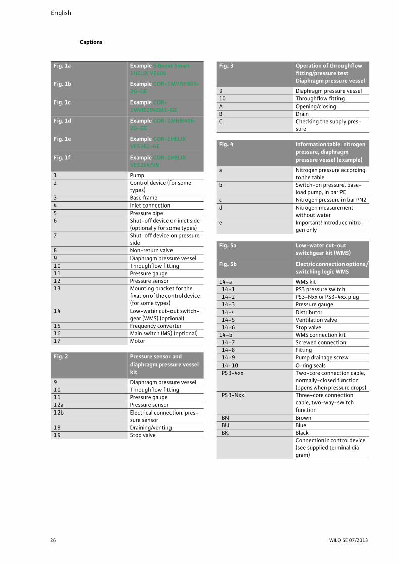
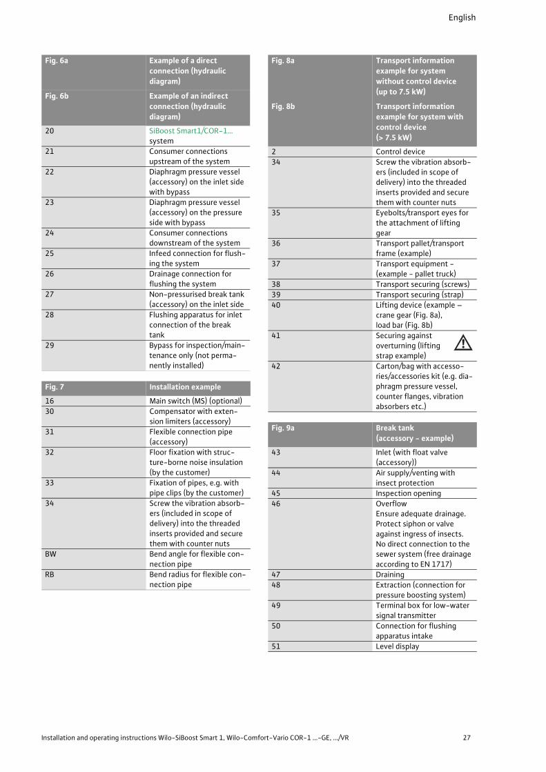
46 Overflow Ensure adequate drainage. Protect siphon or valve against ingress of insects. No direct connection to the sewer system (free drainage according to EN 1717)
47 Draining
48 Extraction (connection for pressure boosting system)
1 General ..................................................................................................................................................31
2 Safety ....................................................................................................................................................312.1 Indication of instructions in the operating instructions .................................................................................312.2 Personnel qualifications ......................................................................................................................................312.3 Danger in the event of non-observance of the safety instructions ..............................................................312.4 Safety consciousness on the job ........................................................................................................................312.5 Safety instructions for the operator .................................................................................................................312.6 Safety instructions for installation and maintenance work ...........................................................................322.7 Unauthorised modification and manufacture of spare parts ..........................................................................322.8 Improper use ........................................................................................................................................................32
3 Transport and interim storage ...........................................................................................................32
4 Intended use .........................................................................................................................................33
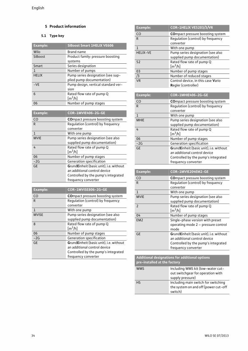
5 Product information ............................................................................................................................345.1 Type key ................................................................................................................................................................345.2 Technical data 355.3 Scope of delivery .................................................................................................................................................365.4 Accessories ...........................................................................................................................................................36
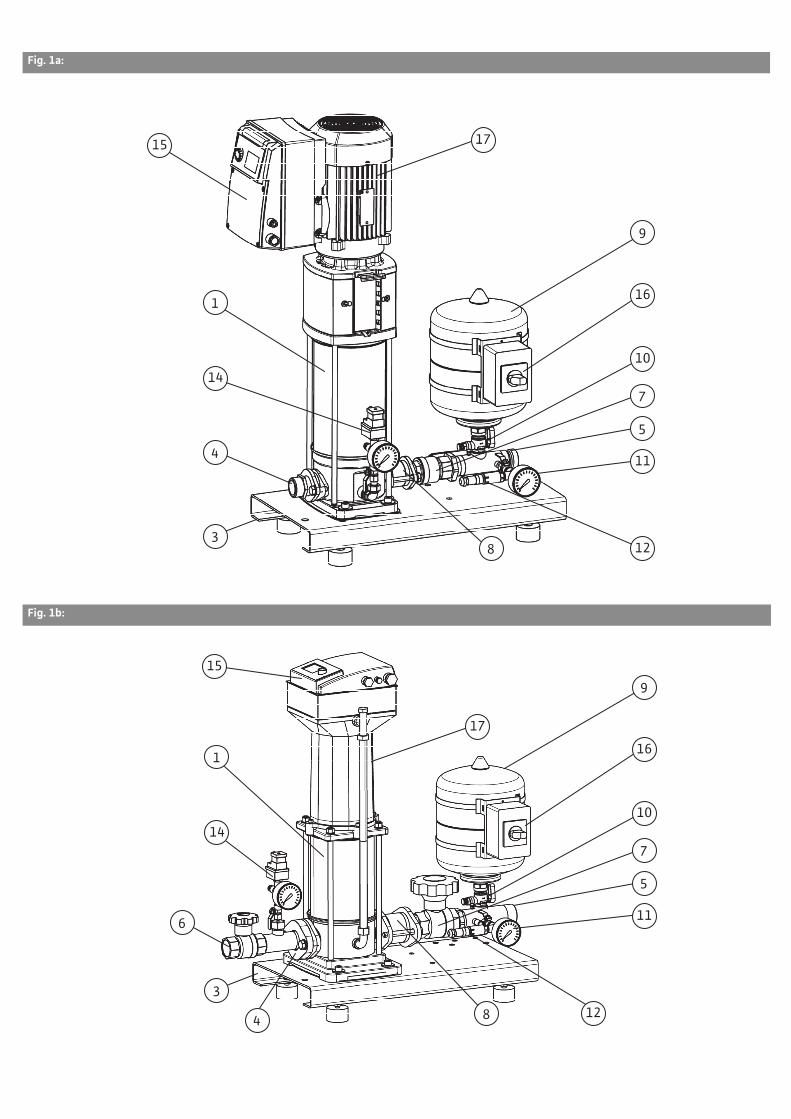
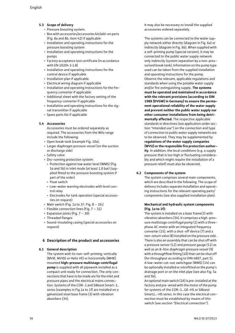
6 Description of the product and accessories .....................................................................................366.1 General description .............................................................................................................................................366.2 Components of the system ................................................................................................................................366.3 Function of the system .......................................................................................................................................376.4 Noise .....................................................................................................................................................................38
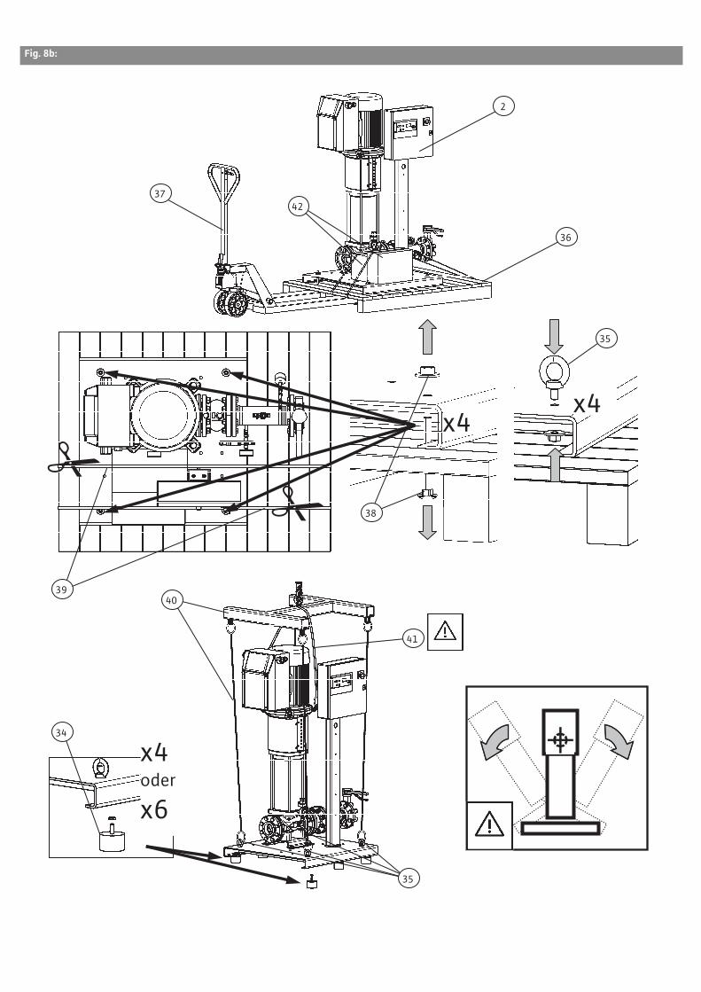
7 Setup/installation ................................................................................................................................387.1 Installation site ....................................................................................................................................................387.2 Installation ............................................................................................................................................................387.2.1 Foundation/bearing surface ...............................................................................................................................387.2.2 Hydraulic connection and pipes .........................................................................................................................387.2.3 Hygiene (TrinkwV 2001) .....................................................................................................................................387.2.4 Protection against dry running/low water level (accessory) ..........................................................................397.2.5 Main switch (accessories) ...................................................................................................................................397.2.6 Diaphragm pressure tank (accessory) ...............................................................................................................397.2.7 Safety valve (accessory) .....................................................................................................................................407.2.8 Non-pressurised break tank (accessory) ..........................................................................................................407.2.9 Expansion joints (accessories) ............................................................................................................................407.2.10Flexible connection lines (accessory) ...............................................................................................................417.2.11Pressure reducer (accessory) .............................................................................................................................417.3 Electrical connection ...........................................................................................................................................41
8 Commissioning/decommissioning .....................................................................................................428.1 General preparations and control measures .....................................................................................................428.2 Protection against low water level (WMS) ........................................................................................................428.3 Commissioning the system .................................................................................................................................428.4 Decommissioning the system ............................................................................................................................43
10 Faults, causes and remedies ...............................................................................................................43
11 Spare parts ...........................................................................................................................................46
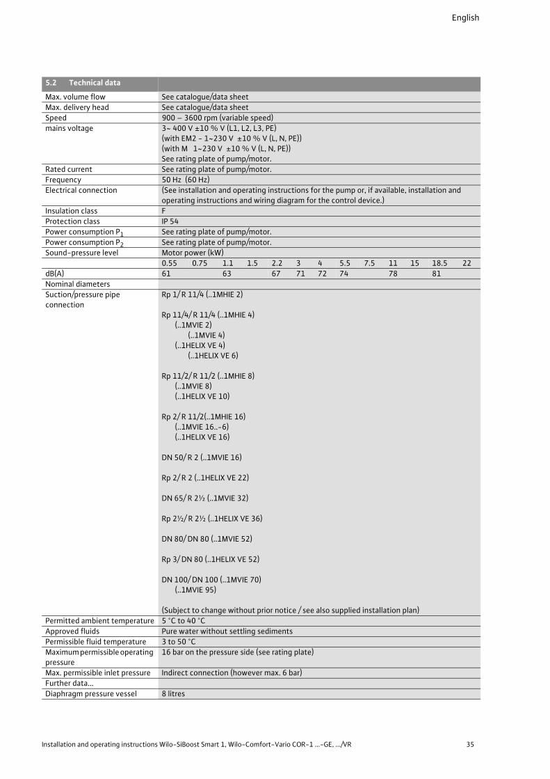
mains voltage 3~ 400 V ±10 % V (L1, L2, L3, PE)(with EM2 - 1~230 V ±10 % V (L, N, PE))(with M 1~230 V ±10 % V (L, N, PE))See rating plate of pump/motor.
Rated current See rating plate of pump/motor.
Frequency 50 Hz (60 Hz)
Electrical connection (See installation and operating instructions for the pump or, if available, installation and operating instructions and wiring diagram for the control device.)
Insulation class F
Protection class IP 54
Power consumption P1 See rating plate of pump/motor.
Power consumption P2 See rating plate of pump/motor.
Sound-pressure level Motor power (kW)
0.55 0.75 1.1 1.5 2.2 3 4 5.5 7.5 11 15 18.5 22
dB(A) 61 63 67 71 72 74 78 81
Nominal diameters
Suction/pressure pipe connection
Rp 1/ R 11/4 (..1MHIE 2)
Rp 11/4/ R 11/4 (..1MHIE 4) (..1MVIE 2)
(..1MVIE 4) (..1HELIX VE 4)
(..1HELIX VE 6)
Rp 11/2/ R 11/2 (..1MHIE 8)(..1MVIE 8)(..1HELIX VE 10)
Rp 2/ R 11/2(..1MHIE 16)(..1MVIE 16..-6)(..1HELIX VE 16)
DN 50/ R 2 (..1MVIE 16)
Rp 2/ R 2 (..1HELIX VE 22)
DN 65/ R 2½ (..1MVIE 32)
Rp 2½/ R 2½ (..1HELIX VE 36)
DN 80/ DN 80 (..1MVIE 52)
Rp 3/ DN 80 (..1HELIX VE 52)
DN 100/ DN 100 (..1MVIE 70)(..1MVIE 95)
(Subject to change without prior notice / see also supplied installation plan)
Permitted ambient temperature 5 °C to 40 °C
Approved fluids Pure water without settling sediments
Expansion joints are subject to wear. It is neces-
sary to regularly check for cracks or blisters,
exposed fabric or other defects (see recommen-
dations in DIN 1988).
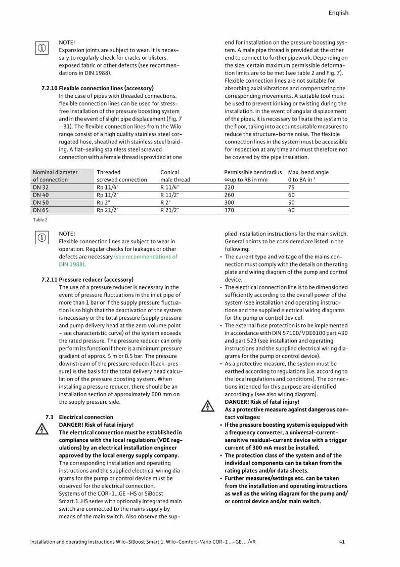
7.2.10 Flexible connection lines (accessory)
In the case of pipes with threaded connections,
flexible connection lines can be used for stress-
free installation of the pressure boosting system
and in the event of slight pipe displacement (Fig. 7
- 31). The flexible connection lines from the Wilo
range consist of a high quality stainless steel cor-
rugated hose, sheathed with stainless steel braid-
ing. A flat-sealing stainless steel screwed
connection with a female thread is provided at one
end for installation on the pressure boosting sys-
tem. A male pipe thread is provided at the other
end to connect to further pipework. Depending on
the size, certain maximum permissible deforma-
tion limits are to be met (see table 2 and Fig. 7).
Flexible connection lines are not suitable for
absorbing axial vibrations and compensating the
corresponding movements. A suitable tool must
be used to prevent kinking or twisting during the
installation. In the event of angular displacement
of the pipes, it is necessary to fixate the system to
the floor, taking into account suitable measures to
reduce the structure-borne noise. The flexible
connection lines in the system must be accessible
for inspection at any time and must therefore not
be covered by the pipe insulation.
Table 2
NOTE!
Flexible connection lines are subject to wear in
operation. Regular checks for leakages or other
defects are necessary (see recommendations of
DIN 1988).
7.2.11 Pressure reducer (accessory)
The use of a pressure reducer is necessary in the
event of pressure fluctuations in the inlet pipe of
more than 1 bar or if the supply pressure fluctua-
tion is so high that the deactivation of the system
is necessary or the total pressure (supply pressure
and pump delivery head at the zero volume point
- see characteristic curve) of the system exceeds
the rated pressure. The pressure reducer can only
perform its function if there is a minimum pressure
gradient of approx. 5 m or 0.5 bar. The pressure
downstream of the pressure reducer (back-pres-
sure) is the basis for the total delivery head calcu-
lation of the pressure boosting system. When
installing a pressure reducer, there should be an
installation section of approximately 600 mm on
the supply pressure side.
7.3 Electrical connection
DANGER! Risk of fatal injury!
The electrical connection must be established in
compliance with the local regulations (VDE reg-
ulations) by an electrical installation engineer
approved by the local energy supply company.
The corresponding installation and operating
instructions and the supplied electrical wiring dia-
grams for the pump or control device must be
observed for the electrical connection.
Systems of the COR-1…GE -HS or SiBoost
Smart.1..HS series with optionally integrated main
switch are connected to the mains supply by
means of the main switch. Also observe the sup-
plied installation instructions for the main switch.
General points to be considered are listed in the
following:
• The current type and voltage of the mains con-
nection must comply with the details on the rating
plate and wiring diagram of the pump and control
device.
• The electrical connection line is to be dimensioned
sufficiently according to the overall power of the
system (see installation and operating instruc-
tions and the supplied electrical wiring diagrams
for the pump or control device).
• The external fuse protection is to be implemented
in accordance with DIN 57100/ VDE0100 part 430
and part 523 (see installation and operating
instructions and the supplied electrical wiring dia-
grams for the pump or control device).
• As a protective measure, the system must be
earthed according to regulations (i.e. according to
the local regulations and conditions). The connec-
tions intended for this purpose are identified
accordingly (see also wiring diagram).
DANGER! Risk of fatal injury!
As a protective measure against dangerous con-
tact voltages:
• If the pressure boosting system is equipped with
a frequency converter, a universal-current-
sensitive residual-current device with a trigger
current of 300 mA must be installed,
• The protection class of the system and of the
individual components can be taken from the
rating plates and/or data sheets.
• Further measures/settings etc. can be taken
from the installation and operating instructions
as well as the wiring diagram for the pump and/
or control device and/or main switch.
Nominal diameterof connection
Threadedscrewed connection
Conicalmale thread
Permissible bend radius ∞up to RB in mm
Max. bend angle0 to BA in °
DN 32 Rp 11/4" R 11/4" 220 75
DN 40 Rp 11/2" R 11/2" 260 60
DN 50 Rp 2" R 2" 300 50
DN 65 Rp 21/2" R 21/2" 370 40
English
42 WILO SE 07/2013
8 Commissioning/decommissioning We recommend that the initial commissioning of the system is performed by Wilo’s customer serv-ice. Contact your dealer, your nearest WILO repre-sentative or contact our central customer service department directly for details.
8.1 General preparations and control measures
• Check that all on-site wiring has been performed correctly, in particular the earthing, prior to the initial start-up.
• Check that the pipes joints are not under stress.• Fill the system and subject it to a visual inspection
for leakages,• Open the shut-off devices at the pumps and in the
suction and pressure piping.• Open the pump venting screws and fill the pumps
slowly with water to allow the air to escape com-pletely.Caution! Risk of property damage!
Do not allow the pump to run dry. Dry running
destroys the mechanical seal and leads to motor
overloading.
• In suction mode (i.e. negative level difference between the break tank and pump), fill the pump and the suction line via the opening in the venting screw (use a funnel if necessary).
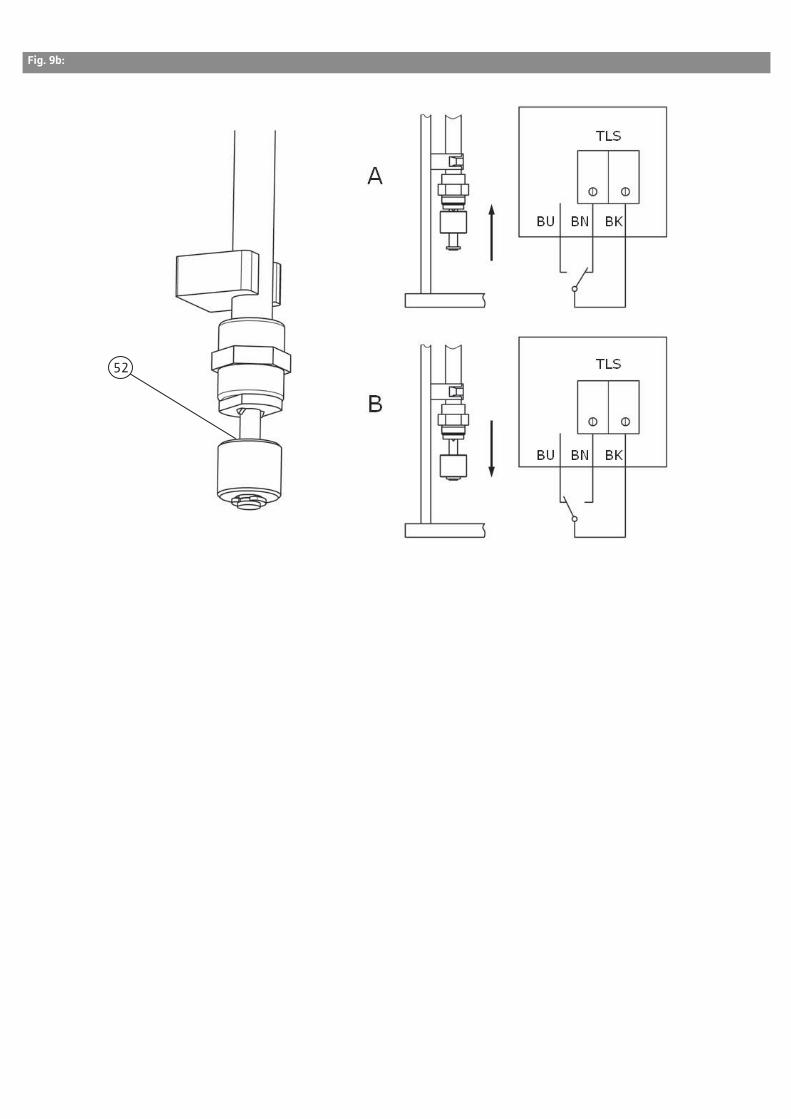
• If a diaphragm pressure vessel (optional or acces-sory) is installed, check whether it is set to the correct supply pressure (see Fig. 3 and 4).
• To do so:• depressurise the vessel on the water side (close
the flow-through fixture (A, Fig. 3) and allow the residual water to drain (B, Fig. 3)),
• Check the gas pressure at the air valve (top; remove protective cap) of the diaphragm pres-sure vessel with an air pressure gauge (C, Fig. 3). If necessary, correct the pressure if too low (PN 2 = pump switch-on pressure pmin less 0.2-0.5 bar) or value given in the table on the vessel (see also Fig. 3) by adding nitrogen (contact Wilo customer service).
• If the pressure is too high, release nitrogen from the valve until the required value is reached. Reapply the protective cap,
• Close the drain valve on the flow-through fix-ture and open the flow-through fixture.
• In the event of system pressures > PN 16, the manufacturer’s filling instructions should be observed for the diaphragm pressure vessel in accordance with the installation and operating instructions.DANGER! Risk of fatal injury!
Excessive supply pressure (nitrogen) in the dia-
phragm pressure vessel can lead to damage or
destruction of the vessel and thereby also to
personal injury.
The safety measures for the handling of pressu-
rised vessels and technical gases must be
observed.
The pressure specifications in this documenta-
tion (Fig. 4) are made in bar(!). If other units of
pressure measurement are used, always be sure
to convert the figures correctly!
• In the case of an indirect connection, check that
the water level in the storage tank is adequate, or
with a direct connection, that the inlet pressure is
adequate (minimum inlet pressure 1 bar)
• Correct installation of the correct dry-running
protection (Section 7.2.4.)
• Position the float switch or electrodes for protec-
tion against low water level in the break tank to
ensure the system is switched off at the minimum
water level (Section 7.2.4).
• Check the motor protection switch in the control
device (COR-1…VR only) to make sure the correct
nominal current is set according to the specifica-
tions of the motor rating plate. Observe the instal-
lation and operating instructions for the control
device when doing so.
• The pumps should run only briefly against the
closed gate valve on the pressure side.
• Check and set the required operating parameters
at the frequency converter of the pump and or
control device in accordance with the supplied
installation and operating instructions.
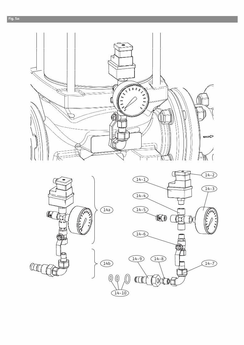
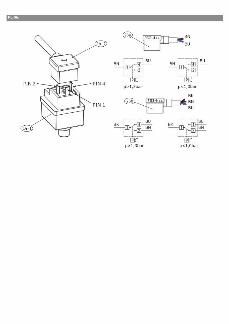
8.2 Protection against low water level (WMS)
The pressure switch (14-1) for the protection
against low water level (WMS) (Fig. 5a and 5b) for
monitoring the supply pressure is permanently
factory-set to the thresholds 1 bar (deactivates if
pressure below this value) and about 1.3 bar
(starts up again when pressure goes above this
value). It is not possible to change these settings.
8.3 Commissioning the system
Once all preparations have been made and all con-
trol measures taken in accordance with Section
8.1:
• The system is to be switched on by means of the
optional main switch in the event of COR-1..GE-
HS or SiBoost Smart-1…HS systems.
• The system is to be switched on by means of the
main switch on the control device and the control
set to automatic mode in the event of systems
with VR CVV control device.
• The system is to be switched on by means of a
separate main switch to be provided by the cus-
tomer in the event of COR-1...GE systems (with-
out main switch installed at the factory).
The pressure control system switches on the
pump until the consumer piping is filled with
water and the set pressure has been built up. It the
pressure no longer changes (no consumer require-
ment within a preset time), the control switches
off the pump. A precise description in this respect
• Switch off the voltage supply and secure it against
being switched on again by unauthorised persons.
• Close the shut-off devices upstream and down-
stream of the system
• Shut off the diaphragm pressure vessel at the
throughflow fitting and drain it
• Drain the system completely if necessary
9 MaintenanceTo guarantee maximum operational reliability at
the lowest possible operating costs, we recom-
mend that the system is checked and maintained
regularly (see DIN 1988 standard). It is advisable to
conclude a maintenance contract with a specialist
company or with our central customer service. The
following checks should be made regularly:
• Inspection of the operational readiness of the
pressure boosting system
• Inspection of the mechanical seal of the pump.
The mechanical seals require water for lubrication,
that can leak out of the seal slightly. If this is
noticeable, replace the mechanical seal.
• Inspection of the diaphragm pressure vessel
(every 3 months is recommended) to make sure
the correct supply pressure is set (see Fig. 3 and
Fig. 4).
Caution! Risk of property damage!
If the supply pressure is incorrect, the function
of the diaphragm pressure vessel is not guaran-
teed, which increases the diaphragm wear and
can cause system faults.
• In this case, depressurise the vessel on the water
side (close the flow-through fixture
(A, Fig. 3) and allow the residual water to drain
(B, Fig. 3)).
• Check the gas pressure at the diaphragm pres-
sure vessel valve (top; remove protective cap)
with an air pressure gauge (C, Fig. 3)
• If necessary, correct the pressure by filling nitro-
gen (PN2 = pump start-up pressure pmin minus
0.2–0.5 bar or value specified in the table on the
vessel (Fig. 4) - Wilo customer service).
• If the pressure is too high, discharge nitrogen
from the valve.
Caution!
Excessive supply pressure (nitrogen) in the dia-
phragm pressure vessel can lead to damage or
destruction of the vessel and thereby also to
personal injury.
The safety measures for the handling of pressu-
rised vessels and technical gases must be
observed.
The pressure specifications in this documenta-
tion (Fig. 5) are made in bar. If other units of
pressure measurement are used, always be sure
to convert the figures correctly!
• In the case of installations with a frequency con-
verter, the inlet and outlet filter of the fan must be
cleaned if they are very dirty.
If the system is decommissioned for a long period,
proceed as described in 8.4 and drain the pump by
opening the drain plug at the pump base. (Also
observe the corresponding section in the supplied
installation and operating instructions for the
pump)
10 Faults, causes and remediesFaults, particularly those affecting the pumps or
the control system, should only be remedied by
Wilo’s customer service or a specialist company.
NOTE!
The general safety instructions must be observed
during any maintenance or repair work. Please also
observe the installation and operating instruc-
tions for the pump and control device, in particular
for the display of error messages!
The faults specified here are general faults. If
errors are displayed on the display of the fre-
quency converter or control device, make sure you
observe the installation and operating instruc-
tions for these devices.
Fault Cause Remedy
Pump does not start No mains voltage Check the fuses, cables and connections.
Main switch “OFF” Switch on the main switch
Water level in break tank too low, i.e. low-water level reached
Check the break tank's inlet valve/supply line.
Low-water level switch has triggered Check the inlet pressure.
Low-water level switch defective Check and, if necessary, replace the low-water level switch.
Electrodes connected incorrectly or sup-ply pressure switch set incorrectly
Check the installation or setting and cor-rect it.
Inlet pressure is above start-up pressure. Check the default values and correct them if necessary.
Shut-off device closed at pressure sen-sor/switch
Check and open the shut-off device if nec-essary.
Start-up pressure set too high Check the setting and correct it if neces-sary.
English
44 WILO SE 07/2013
Fuse defective Check fuses and replace if necessary
Motor protection has triggered Check the default values against the pump or motor data, measure the current values and correct the setting if necessary. Check the motor for defects and replace it if nec-essary.
Contactor defective Check it and replace it if necessary.
Turn-to-turn fault in the motor Check, if necessary replace motor or have repaired.
Pump does not shut down. Strongly fluctuating inlet pressure Check the inlet pressure and take measures to stabilise the inlet pressure if necessary (e.g. pressure reducers).
Intake pipe blocked or shut off Check the inlet pipe and remove the block-age or open the shut-off device if neces-sary.
Nominal diameter of the inlet pipe too small
Check the inlet pipe and increase the cross-section of the inlet pipe if necessary.
Inlet pipe installed incorrectly Check the inlet pipe and change the pipe routing if necessary.
Air in the inlet Check and shut off the piping and vent the pumps if necessary.
Impellers blocked Check the pump and replace it or have it repaired if necessary.
Non-return valve leaking Check and replace the seal or non-return valve if necessary.
Non-return valve blocked Check and remove the blockage or replace the non-return valve if necessary.
Gate valve in the system closed or not sufficiently open
Check and open the shut-off device com-pletely if necessary.
Flow rate too high Check the pump data and default values and correct them if necessary.
Shut-off device closed at pressure sensor Check and open the shut-off device if nec-essary.
Switch-off pressure set too high Check the setting and correct it if neces-sary.
Incorrect direction of rotation of the motor
Check the direction of rotation and repair or replace the frequency converter module if necessary.
Switching frequency too high or flut-tering
Major fluctuations of the inlet pressure Check the inlet pressure and take measures to stabilise the inlet pressure if necessary (e.g. pressure reducers).
Intake pipe blocked or shut off Check the inlet pipe and remove the block-age or open the shut-off device if neces-sary.
Nominal diameter of the inlet pipe too small
Check the inlet pipe and increase the cross-section of the inlet pipe if necessary.
Inlet pipe installed incorrectly Check the inlet pipe and change the pipe routing if necessary.
Shut-off device closed at pressure sensor Check and open the shut-off device if nec-essary.
Incorrect supply pressure at diaphragm pressure vessel
Check the supply pressure and correct it if necessary.
Valve at diaphragm pressure vessel closed
Check the valve and open it if necessary.
Switching difference set too low Check the setting and correct it if neces-sary.
Pump not stable and/or making unusual noises
Major fluctuations of the inlet pressure Check the inlet pressure and take measures to stabilise the inlet pressure if necessary (e.g. pressure reducers).
Intake pipe blocked or shut off Check the inlet pipe and remove the block-age or open the shut-off device if neces-sary.
Check the inlet pipe and increase the cross-section of the inlet pipe if necessary.
Inlet pipe installed incorrectly Check the inlet pipe and change the pipe routing if necessary.
Air in the inlet Check and shut off the piping and vent the pumps if necessary.
Air in the pump Vent the pump, check the suction line for leakages and seal it if necessary.
Impellers blocked Check the pump and replace it or have it repaired if necessary.
Flow rate too high Check the pump data and default values and correct them if necessary.
Incorrect direction of rotation of the motors
Check the direction of rotation and repair or replace the frequency converter module if necessary.
Mains voltage: a phase is missing Check the fuses, cables and connections.
Pump not adequately secured to base frame
Check the fixation and re-tighten the fas-tening screws if necessary.
Bearing damage Check the pump/motor and replace it or have it repaired if necessary.
Motor or pump become too warm Air in the inlet Check and shut off the piping and vent the pumps if necessary.
Gate valve in the system closed or not sufficiently open
Check and open the shut-off device com-pletely if necessary.
Impellers blocked Check the pump and replace it or have it repaired if necessary.
Non-return valve blocked Check and remove the blockage or replace the non-return valve if necessary.
Shut-off device closed at pressure sensor Check and open the shut-off device if nec-essary.
Switch-off point set too high Check the setting and correct it if neces-sary.
Bearing damage Check the pump/motor and replace it or have it repaired if necessary.
Turn-to-turn fault in the motor Check, if necessary replace motor or have repaired.
Mains voltage: a phase is missing Check the fuses, cables and connections.
Current consumption too high Non-return valve leaking Check and replace the seal or non-return valve if necessary.
Flow rate too high Check the pump data and default values and correct them if necessary.
Turn-to-turn fault in the motor Check, if necessary replace motor or have repaired.
Mains voltage: a phase is missing Check the fuses, cables and connections.
Motor protection switch triggers Non-return valve defective Check and replace the non-return valve if necessary.
Flow rate too high Check the pump data and default values and correct them if necessary.
Contactor defective Check it and replace it if necessary.
Turn-to-turn fault in the motor Check, if necessary replace motor or have repaired.
Mains voltage: a phase is missing Check the fuses, cables and connections.
Pump generates no or insufficient power
Major fluctuations of the inlet pressure Check the inlet pressure and take measures to stabilise the inlet pressure if necessary (e.g. pressure reducers).
Intake pipe blocked or shut off Check the inlet pipe and remove the block-age or open the shut-off device if neces-sary.
Nominal diameter of the inlet pipe too small
Check the inlet pipe and increase the cross-section of the inlet pipe if necessary.
Inlet pipe installed incorrectly Check the inlet pipe and change the pipe routing if necessary.
Fault Cause Remedy
English
46 WILO SE 07/2013
NOTE!
You can find information on pump or control
device faults not dealt with here in the supplied
documentation for the components concerned.
If the operating fault cannot be remedied,
please consult a specialist company or your
nearest Wilo customer service or representa-
tive.
11 Spare partsSpare parts or repairs may be ordered from local
specialist retailers or Wilo customer service.
To avoid queries and incorrect orders, all data of
the rating plate should be submitted for each
order.
Subject to change without prior notice!
Air in the inlet Check and shut off the piping and vent the pumps if necessary.
Impellers blocked Check the pump and replace it or have it repaired if necessary.
Non-return valve leaking Check and replace the seal or non-return valve if necessary.
Non-return valve blocked Check and remove the blockage or replace the non-return valve if necessary.
Gate valve in the system closed or not sufficiently open
Check and open the shut-off device com-pletely if necessary.
Low-water level switch has triggered Check the inlet pressure.
Pump generates no or insufficient power
Incorrect direction of rotation of the motor
Check the direction of rotation and repair or replace the frequency converter module if necessary.
Turn-to-turn fault in the motor Check, if necessary replace motor or have repaired.
Dry-running protection switches off although water is present
Major fluctuations of the inlet pressure Check the inlet pressure and take measures to stabilise the inlet pressure if necessary (e.g. pressure reducers).
Nominal diameter of the inlet pipe too small
Check the inlet pipe and increase the cross-section of the inlet pipe if necessary.
Inlet pipe installed incorrectly Check the inlet pipe and change the pipe routing if necessary.
Flow rate too high Check the pump data and default values and correct them if necessary.
Electrodes connected incorrectly or sup-ply pressure switch set incorrectly
Check the installation or setting and cor-rect it.
Low-water level switch defective Check and, if necessary, replace the low-water level switch.
Dry-running protection does not switch off in spite of low water
Electrodes connected incorrectly or sup-ply pressure switch set incorrectly
Check the installation or setting and cor-rect it.
Low-water level switch defective Check and, if necessary, replace the low-water level switch.
conforme 2006/42/CE appendice II,1A et 2004/108/CE appendice IV,2) Hiermit erklären wir, dass die Nassläufer-Umwälzpumpen der Baureihe : CO(R)- � Helix V � Herewith, we declare that the glandless circulating pumps of the series: COR- � Helix VE � Par le présent, nous déclarons que les circulateurs des séries : SiBoost Smart Helix V(E) SiBoost Smart Helix EXCEL (Die Seriennummer ist auf dem Typenschild des Produktes angegeben. / The serial number is marked on the product site plat. / Le numéro de série est inscrit sur la plaque signalétique du produit.)
in der gelieferten Ausführung folgenden einschlägigen Bestimmungen entspricht:in its delivered state complies with the following relevant provisions:est conforme aux dispositions suivantes dont il relève:
EG-Maschinenrichtlinie 2006/42/EG EC-Machinery directive Directives CE relatives aux machines Die Schutzziele der Niederspannungsrichtlinie 2006/95/EG werden gemäß Anhang I, Nr. 1.5.1 der Maschinenrichtlinie 2006/42/EG eingehalten / The protection objectives of the low-voltage directive 2006/95/EC are realized according annex I, No. 1.5.1 of the EC-Machinery directive 2006/42/EC / Les objectifs protection de la directive basse-tension 2006/95/CE sont respectées conformément à appendice I, no 1.5.1 de la directive CE relatives aux machines 2006/42/CE.
angewendete harmonisierte Normen, insbesondere: EN ISO 12100, EN 60204-1,as well as following harmonized standards: EN 61000-6-1, ainsi qu�aux normes harmonisées suivantes: EN 61000-6-2, EN 61000-6-3, EN 61000-6-4
Bei einer mit uns nicht abgestimmten technischen Änderung der oben genannten Bauarten, verliert diese Erklärung ihre Gültigkeit. If the above mentioned series are technically modified without our approval, this declaration shall no longer be applicable. Si les pompes mentionnées ci-dessus sont modifiées sans notre approbation, cette déclaration perdra sa validité.
Bevollmächtigter für die Zusammenstellung der technischen Unterlagen ist:Authorized representative for the completion of the technical documentation: Mandataire pour le complément de la documentation technique est :
Pompes Salmson S.A. - Laval Division Pumps & Systems PBU Multistage & Domestic Pumps - Quality 80 Bd de l�Industrie BP 0527 F-52005 Laval Cédex
Dortmund, 13.02.2012
Oliver Breuing
Quality Manager
WILO SE Nortkirchenstraße 100 44263 Dortmund Germany
Document: 2117801.1
NL IT ESEG-verklaring van overeenstemming Dichiarazione di conformità CE Declaración de conformidad CEHiermede verklaren wij dat dit aggregaat in de geleverde uitvoering voldoet aan de volgende bepalingen:
Con la presente si dichiara che i presenti prodotti sono conformi alle seguenti disposizioni e direttive rilevanti:
Por la presente declaramos la conformidad del producto en su estado de suministro con las disposiciones pertinentes siguientes:
EG-richtlijnen betreffende machines 2006/42/EG Direttiva macchine 2006/42/EG Directiva sobre máquinas 2006/42/EGElektromagnetische compatibiliteit 2004/108/EG Compatibilità elettromagnetica 2004/108/EG Directiva sobre compatibilidad electromagnética 2004/108/EGgebruikte geharmoniseerde normen, in het bijzonder: norme armonizzate applicate, in particolare: normas armonizadas adoptadas, especialmente:zie vorige pagina vedi pagina precedente véase página anterior
PT SV NODeclaração de Conformidade CE CE- försäkran EU-OverensstemmelseserklæringPela presente, declaramos que esta unidade no seu estado original, está conforme os seguintes requisitos:
Härmed förklarar vi att denna maskin i levererat utförande motsvarar följande tillämpliga bestämmelser:
Vi erklærer hermed at denne enheten i utførelse som levert er i overensstemmelse med følgende relevante bestemmelser:
Directivas CEE relativas a máquinas 2006/42/EG EG�Maskindirektiv 2006/42/EG EG�Maskindirektiv 2006/42/EGCompatibilidade electromagnética 2004/108/EG EG�Elektromagnetisk kompatibilitet � riktlinje 2004/108/EG EG�EMV�Elektromagnetisk kompatibilitet 2004/108/EGnormas harmonizadas aplicadas, especialmente: tillämpade harmoniserade normer, i synnerhet: anvendte harmoniserte standarder, særlig:ver página anterior se föregående sida se forrige side
FI DA HUCE-standardinmukaisuusseloste EF-overensstemmelseserklæring EK-megfelel�ségi nyilatkozatIlmoitamme täten, että tämä laite vastaa seuraavia asiaankuuluvia määräyksiä:
Vi erklærer hermed, at denne enhed ved levering overholder følgende relevante bestemmelser:
Ezennel kijelentjük, hogy az berendezés megfelel az alábbi irányelveknek:
EU�konedirektiivit: 2006/42/EG EU�maskindirektiver 2006/42/EG Gépek irányelv: 2006/42/EKSähkömagneettinen soveltuvuus 2004/108/EG Elektromagnetisk kompatibilitet: 2004/108/EG Elektromágneses összeférhet�ség irányelv: 2004/108/EKkäytetyt yhteensovitetut standardit, erityisesti: anvendte harmoniserede standarder, særligt: alkalmazott harmonizált szabványoknak, különösen:katso edellinen sivu. se forrige side lásd az el�z� oldalt
CS PL RUProhlá�ení o shod� ES Deklaracja Zgodno�ci WE ��� ���� � ����������� �� ������ �� ���Prohla�ujeme tímto, �e tento agregát v�dodaném provedení odpovídá následujícím p�íslu�ným ustanovením:
Niniejszym deklarujemy z pe�n odpowiedzialnoci, �e dostarczony wyrób jest zgodny z nast�pujcymi dokumentami:
pou�ité harmoniza*ní normy, zejména: stosowanymi normami zharmonizowanymi, a w szczególnoci: +�'��;������ ��"���������� ������#�� � ��#��, � ��������� :
viz p�edchozí strana patrz poprzednia strona ��. '#�������) ��#���<�
EL TR RO$%&'*+ *5779;<'*+= >+= ?? CE Uygunluk Teyid Belgesi EC-Declara@ie de conformitate=>?@JKXY[ \]^ ]K _`K{\J |X]\ }� |X]~ ]>J �|]�}]|}> _|`��K}>� ^�|JK_K^[� ]^� |�\?KX�[� �^|]��[^� :
Bu cihaz�n teslim edildi�i �ekliyle a�a��daki standartlara uygun oldu�unu teyid ederiz:
Prin prezenta declar�m c� acest produs a�a cum este livrat, corespunde cu urm�toarele prevederi aplicabile:
JQ+Y[\= E] Y^_ 7+`_{%7_>_ 2006/42/E] AB-Makina Standartlar| 2006/42/EG Directiva CE pentru ma}ini 2006/42/EG~&\�>;�7_Y{+>^�% *57�_>9>+>_ E]-2004/108/E] Elektromanyetik Uyumluluk 2004/108/EG Compatibilitatea electromagnetic� � directiva 2004/108/EG�J|`YKJ^}Y�J| �`>}^YK_K^K�Y[J| _`\]X_|, ^�^|�][`|: k�smen kullan�lan standartlar için: standarde armonizate aplicate, îndeosebi:�?�_[ _`K>�K�Y[J> }[?��| bkz. bir önceki sayfa vezi pagina precedent�
ET LV LTEÜ vastavusdeklaratsioon EC - atbilst�bas deklar�cija EB atitikties deklaracijaKäesolevaga tõendame, et see toode vastab järgmistele asjakohastele direktiividele:
Ar �o m�s apliecin�m, ka �is izstr�d�jums atbilst sekojo�iem noteikumiem:
�iuo pa�ymima, kad �is gaminys atitinka �ias normas ir direktyvas:
SK SL BGES vyhlásenie o zhode ES � izjava o skladnosti E�-��� ���� �� ����������Týmto vyhlasujeme, �e kon�trukcie tejto kon�truk*nej série v dodanom vyhotovení vyhovujú nasledujúcim príslu�ným ustanoveniam:
Izjavljamo, da dobavljene vrste izvedbe te serije ustrezajo slede*im zadevnim dolo*ilom:
Stroje - smernica 2006/42/ES Direktiva o strojih 2006/42/ES ������� �� ���� 2006/42/EOElektromagnetická zhoda - smernica 2004/108/ES Direktiva o elektromagnetni zdru�ljivosti 2004/108/ES E�� ��������� ���������� � �� ���� 2004/108/E�pou�ívané harmonizované normy, najmä: uporabljeni harmonizirani standardi, predvsem: ��#������#��� ������#��:pozri predchádzajúcu stranu glejte prej�njo stran ��. '#������ ��#���<�
MT HR SRDikjarazzjoni ta� konformità KE EZ izjava o sukladnosti EZ izjava o uskla�enostiB'dan il-mezz, niddikjaraw li l-prodotti tas-serje jissodisfaw id-dispo�izzjonijiet relevanti li �ejjin:
Ovim izjavljujemo da vrste konstrukcije serije u isporu*enoj izvedbi odgovaraju sljede�im va�e�im propisima:
Ovim izjavljujemo da vrste konstrukcije serije u isporu*enoj verziji odgovaraju slede�im va�e�im propisima:
Makkinarju - Direttiva 2006/42/KE EZ smjernica o strojevima 2006/42/EZ EZ direktiva za ma�ine 2006/42/EZKompatibbiltà elettromanjetika - Direttiva 2004/108/KE Elektromagnetna kompatibilnost - smjernica 2004/108/EZ Elektromagnetna kompatibilnost - direktiva 2004/108/EZb'mod partikolari: primijenjene harmonizirane norme, posebno: primenjeni harmonizovani standardi, a posebno: ara l-pa�na ta' qabel vidjeti prethodnu stranicu vidi prethodnu stranu
ÖsterreichZentrale Wiener Neudorf:WILO Pumpen Österreich GmbH Wilo Straße 1 A-2351 Wiener Neudorf T +43 507 507-0 F +43 507 507-15 [email protected] www.wilo.at
Vertriebsbüro Salzburg:Gnigler Straße 56 A-5020 Salzburg T +43 507 507-13 F +43 662 878470 [email protected] www.wilo.at
Vertriebsbüro Oberösterreich:Trattnachtalstraße 7 A-4710 Grieskirchen T +43 507 507-26 F +43 7248 65054 [email protected] www.wilo.at
SchweizEMB Pumpen AG Gerstenweg 7 CH-4310 Rheinfelden T +41 61 83680-20 F +41 61 83680-21 [email protected] www.emb-pumpen.ch
Erreichbar Mo–Do 7-18 Uhr, Fr 7-17 Uhr.
– Antworten auf – Produkt- und Anwendungsfragen – Liefertermine und Lieferzeiten