19
1 ESS 034 Advanced Photovoltaic Systems Wire Sizing 2 Energy 143 Solar Photovoltaic Systems Design, Installation, and Troubleshooting

1ESS 034
Advanced Photovoltaic Systems
Wire Sizing 2
Energy 143 Solar Photovoltaic Systems Design, Installation, and Troubleshooting

2ESS 034
Advanced Photovoltaic Systems
Lesson Plan
• Conductors, PV, and NEC– Conductor sizing and ampacity
– Voltage drop
• Next week Conduit– We will be bending conduit so shoes are required

3
• Ampacity is the current-carrying capacity of a conductor and depends on conductor type and size.
• From NEC tables 310.16 and 310.17

4• Conductor ampacity must be derated for high temperatures.

5
• Conductor ampacity must be derated for more than three current- carrying conductors together in a conduit or cable.

6
Cable sizing and over current protection
ESS 034 Advanced Photovoltaic Systems
1. Circuit current. For circuits carrying DC current from PV modules, multiply the short circuit current by 125% and use this value for all further calculations. This is called the CONTINUOUS CURRENT calculation.
• Isc = 8.0
• Continuous current = ISC * 1.25 =
What is continuous current calculation for AC currents?
What is continuous current calculation from battery banks?
10.0A
Rated continuous current – do not multiply by 125% at this step
Rated AC output at lowest battery voltage

7
Cable sizing and over current protection
ESS 034 Advanced Photovoltaic Systems
2. Over current device rating. The over current device must be rated at 125% of the current determined in step 1. This calculation is often referred to as the 80% OPERATION current.
• Isc = 8.0
• Over current = ISC * 1.25 * 1.25 =
What is over current rating for AC currents?
What is continuous current calculation from battery banks?
12.5A
Rated continuous current * 125%
(Rated AC output /lowest voltage / inverter eff) * 125%

8
Cable sizing and over current protection
3. Cable sizing. Conductors shall have a 30C ampacity of 125% of the continuous current to ensure proper operation of the connected over current devices.
• Isc = 8.0
• Conductor ampacity = ISC * 1.25 * 1.25 =
4. Cable derating. Based on the location of the conductor, conductor size, and temperature rating it may need to be de- rated. The resulting de-rated ampacity must be greater than value in step 1.
• 14AWG, THWN-2 in conduit with 4 current carrying conductors, ambient temp = 150F
• De-rated ampacity =
12.5A
25A * .80 * .58 = 11.6A

9
Cable sizing and over current protection
5. Ampacity vs over current device. The de-rated ampacity of step 4 must be equal to or greater than the over current device rating calculated in step 2. If the de-rated ampacity of the cable is less then the over current device rating than a larger cable must be selected.
• De-rated ampacity =
• Over current device rating =
6. Device terminal compatibility. Most over current devices have terminal ratings of 75C so compatibility must be verified if 90C insulated cable was selected. The 30C current of the same size conductor with the 75C insulation must be greater than the current found in step 2.

10
Cable sizing and over current protection
7. Device Mounting. If the over current device is mounted in a location that has an ambient temperature higher than 40C then the rating of the device must be adjusted per manufacturer’s specifications.
Example 1 (we do together):• 2 PV circuits in conduit (separate circuits, size individually)
• Isc = 40amps
• Ambient temperature of conductors= 45C
• Over current device terminal rating = 75C
• Ambient temperature of over current device = 40C
What do we do?
11
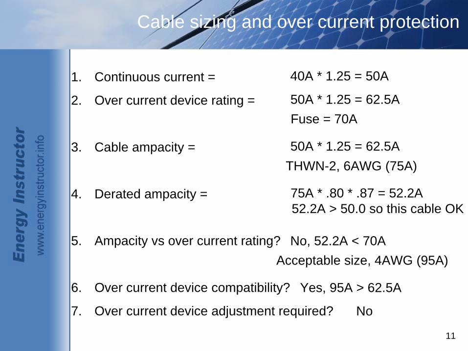
Cable sizing and over current protection
1. Continuous current =
2. Over current device rating =
3. Cable ampacity =
4. Derated ampacity =
5. Ampacity vs over current rating?
6. Over current device compatibility?
7. Over current device adjustment required?
40A * 1.25 = 50A
50A * 1.25 = 62.5A Fuse = 70A
50A * 1.25 = 62.5A THWN-2, 6AWG (75A)
75A * .80 * .87 = 52.2A 52.2A > 50.0 so this cable OK
No, 52.2A < 70A Acceptable size, 4AWG (95A)
Yes, 95A > 62.5A
No
12
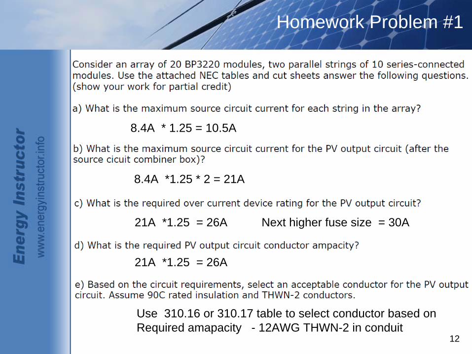
Homework Problem #1
8.4A * 1.25 = 10.5A
8.4A *1.25 * 2 = 21A
21A *1.25 = 26A Next higher fuse size = 30A
21A *1.25 = 26A
Use 310.16 or 310.17 table to select conductor based on Required amapacity - 12AWG THWN-2 in conduit
13
Homework Problem #1
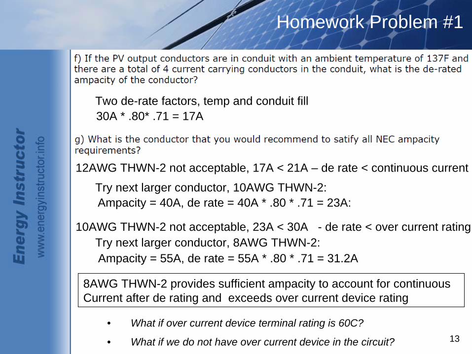
• What if over current device terminal rating is 60C?
• What if we do not have over current device in the circuit?
Two de-rate factors, temp and conduit fill30A * .80* .71 = 17A
12AWG THWN-2 not acceptable, 17A < 21A – de rate < continuous current
Try next larger conductor, 10AWG THWN-2:Ampacity = 40A, de rate = 40A * .80 * .71 = 23A:
10AWG THWN-2 not acceptable, 23A < 30A - de rate < over current ratingTry next larger conductor, 8AWG THWN-2:Ampacity = 55A, de rate = 55A * .80 * .71 = 31.2A
8AWG THWN-2 provides sufficient ampacity to account for continuousCurrent after de rating and exceeds over current device rating

14
Homework Problem #2
8.4A * 1.25 = 10.5A
8.4A *1.25 * 4 = 42A
42A *1.25 = 52.5A Next higher fuse size = 60A
42A *1.25 = 52.5A
Use 310.16 or 310.17 table to select conductor based on Required amapacity - 8AWG USE-2 in free air

15
Homework Problem #2
One de-rate factors, temp and No conduit fill80A * .58 = 46A
8AWG USE-2 not acceptable, 46A < 60A – de rate < over current rating
Try next larger conductor, 6AWG USE-2:Ampacity = 105A, de rate = 105A * .58 = 61A
6AWG USE-2 provides sufficient ampacity to account for continuouscurrent after de rating and exceeds over current device rating
Look at ampacity of the same conductor with lower temp rating of theOver current device. That ampacity must exceed over current deviceAmpacity.

16
Cable sizing and over current protection
Example 2 (breakout into groups and try):• Array size: 4 12-volt, 60Watt modules
• Isc = 3.8A, Voc = 21.1
• Ambient temperature of conductors= 150F
• Over current device terminal rating = 140F
• Ambient temperature of over current device = 96F
What do we do?

17
Cable sizing and over current protection
1. Continuous current =
2. Over current device rating =
3. Cable ampacity =
4. Derated ampacity =
5. Ampacity vs over current rating?
6. Over current device compatibility?
7. Over current device adjustment required?
3.8A * 4 * 1.25 = 19A
19A * 1.25 = 23.75A Fuse = 25A
19A * 1.25 = 23.75A USE-2, 10AWG
55A * .58 = 32A 32A > 19 so OK
32A > 25A Acceptable size, 10AWG
10AWG USE-2 at 60C = 40A
No
18
Cable sizing and over current protection
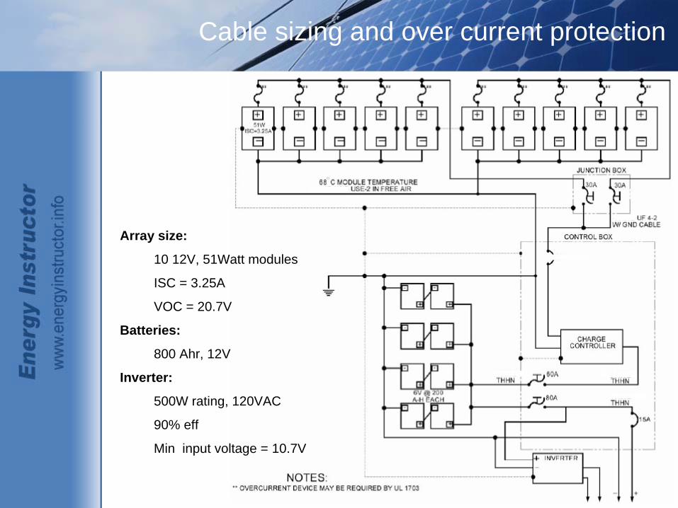
Array size:
10 12V, 51Watt modules
ISC = 3.25A
VOC = 20.7V
Batteries:
800 Ahr, 12V
Inverter:
500W rating, 120VAC
90% eff
Min input voltage = 10.7V

19
Cable sizing and over current protection
Example 3 (breakout into groups and try):
• Size source circuit conductors for the two sub-arrays (USE-2 rated in free air, 68C ambient)
• Size the combined circuit conductors from junction box (UF conductor directly buried, 40C ambient)
• Size the inverter output conductor (THWN in conduit with 4 current carrying conductors, 40C ambient)
• Size the battery to inverter to conductors (THHN in free air, 40C ambient temperature)


