62
Wireless Communications Instructor: Fatima Naseem Computer Engineering Department, University of Engineering and Technology, Taxila
| Date post: | 02-Jan-2016 |
| Category: |
Documents |
| Upload: | jescie-moore |
| View: | 26 times |
| Download: | 3 times |

Wireless Communications
Instructor: Fatima Naseem
Computer Engineering Department, University of Engineering and Technology, Taxila

Contact
Fatima Naseem
Room # 17, CED.
Student meeting time:
Monday 8:00 am to 11:00 am

Course Books
“Wireless Communications and Networks” by William Stallings, Second edition.
Reference Book: “Wireless Communications” by T.S Rappaport,
2nd Edition Pearson Education Refered papers will be given as course will
proceed.

Prerequisites
Computer Communications And Networks Digital Communications Antenna and Wave Theory

Course Timeline Week 1: Chapter 2,3 (Transmission fundamentals &
Communication networks) Week 2: Chapter 4,5 (Protocols and TCP/IP suite &
Antennas and Propagation) Week 3 : Chapter 6 (Signal Encoding techniques) Week 4 : Chapter 6 Week 5 : Chapter 7(Spread Spectrum) Week 6 : Chapter 7 Week 7 : Chapter 8(Coding and Error Control) Week 8 : Chapter 8

Course Timeline
Week 9: Intro to Wireless Networks & Its Types Week 10:Intro to Wireless LAN Week 11:802.11 Week 12:Cellular Technology Week 13:Mobile Generations Week 14:802.16 Week 15:802.15 Week 16:Miscellaneous

Grading Policy: Quiz = 5% Assignments = 5% Mid = 20% Final Paper = 40% Labs = 10% Project = 20% Planned Quizzes and Assignments: Quizzes: 4 Assignments: 4 Quizzes will be announced and no makeups will be done Assignments will be accepted till the submission date before the
lecture starts

Project You can work individually or in a group of two. You can select any topic related to wireless preferably any
wireless technology. If you come up with some research based idea you will be
welcomed but study based project is also acceptable. You can discuss your ideas with instructor. Submit your proposals before Tuesday, 22nd Feb., 2011 Project marks distribution Proposal = 3 marks 1st presentation before mid exams = 6 marks 2nd presentation before final exams = 6 marks Project Report = 5 marks

Labs
Matlab Revision Tasks Presentations

Introduction
Wireless Networks

Networking Basics
Two or more connected devices People can share files, peripherals such as
modems, printers and CD-ROM drives etc. When networks at multiple locations are
connected, people can send e-mail,share links to the global internet or conduct video conferences in real time with other remote users.
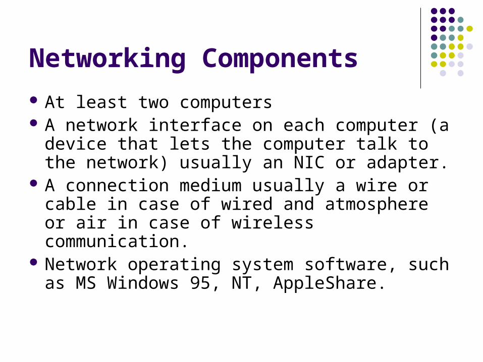
Networking Components
At least two computers A network interface on each computer (a device
that lets the computer talk to the network) usually an NIC or adapter.
A connection medium usually a wire or cable in case of wired and atmosphere or air in case of wireless communication.
Network operating system software, such as MS Windows 95, NT, AppleShare.

Wireless History
Radio invented in the 1880s by Marconi
Many sophisticated military radio systems were developed during and after WW2 Cellular has enjoyed exponential growth since 1988, with almost 3 billion users worldwide today Ignited the wireless revolution Voice, data, and multimedia becoming ubiquitous Use in third world countries growing rapidly
Wifi also enjoying tremendous success and growth Wide area networks (e.g. Wimax) and short-range
systems other than Bluetooth (e.g. UWB) less successful
Ancient Systems: Smoke Signals, Carrier Pigeons, …

Future Wireless NetworksUbiquitous Communication Among People and Devices
Next-generation CellularWireless Internet AccessWireless MultimediaSensor Networks Smart Homes/SpacesAutomated HighwaysIn-Body NetworksAll this and more …

Challenges
Network Challenges Scarce spectrum Demanding/diverse applications Reliability Ubiquitous coverage Seamless indoor/outdoor operation
Device Challenges Size, Power, Cost Multiple Antennas in Silicon Multiradio Integration Coexistance
Cellular
AppsProcessor
BT
MediaProcessor
GPS
WLAN
Wimax
DVB-H
FM/XM

Evolution of Current Systems
Wireless systems today 3G Cellular: ~200-300 Kbps. WLANs: ~450 Mbps (and growing).
Next Generation is in the works 4G Cellular: Likely OFDM/MIMO 4G WLANs: Wide open, 3G just being finalized
Technology Enhancements Hardware: Better batteries. Better circuits/processors. Link: Antennas, modulation, coding, adaptivity, DSP, BW. Network: more efficient resource allocation Application: Soft and adaptive QoS.
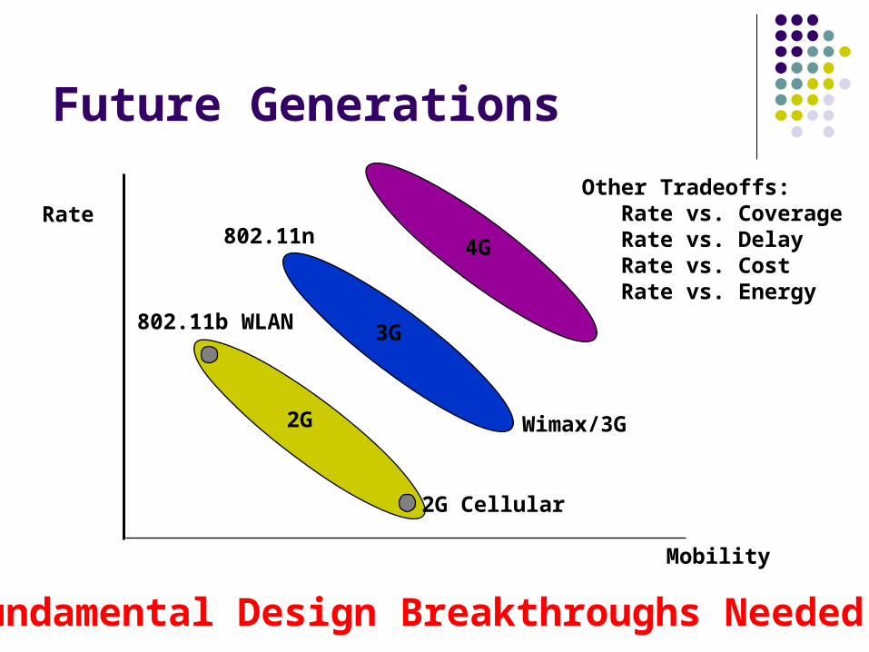
Future Generations
Rate
Mobility
2G
3G
4G
802.11b WLAN
2G Cellular
Other Tradeoffs: Rate vs. Coverage Rate vs. Delay Rate vs. Cost Rate vs. Energy
Fundamental Design Breakthroughs Needed
802.11n
Wimax/3G

Quality-of-Service (QoS)
QoS refers to the requirements associated with a given application, typically rate and delay requirements.
It is hard to make a one-size-fits all network that supports requirements of different applications.
Wired networks often use this approach with poor results, and they have much higher data rates and better reliability than wireless.
QoS for all applications requires a cross-layer design approach.
Transmission Fundamentals
Chapter 2

Electromagnetic Signal
Function of time Can also be expressed as a function of frequency
Signal consists of components of different frequencies
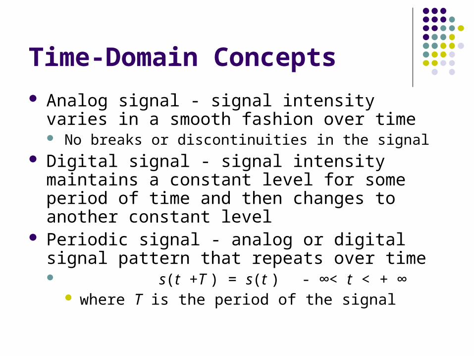
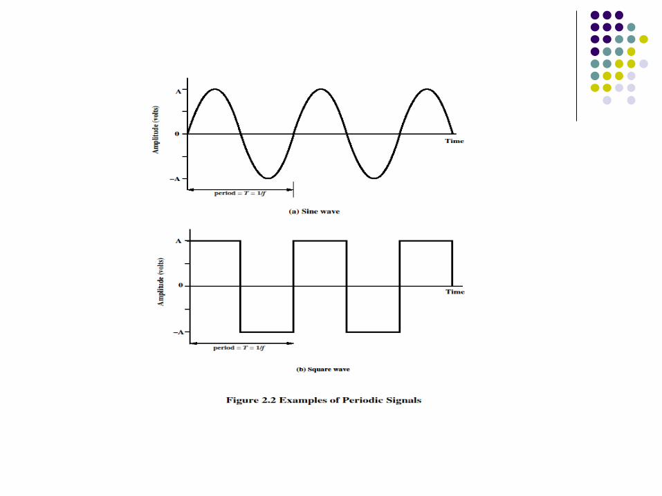
Time-Domain Concepts
Analog signal - signal intensity varies in a smooth fashion over time No breaks or discontinuities in the signal
Digital signal - signal intensity maintains a constant level for some period of time and then changes to another constant level
Periodic signal - analog or digital signal pattern that repeats over time s(t +T ) = s(t ) - ∞< t < + ∞
where T is the period of the signal

Time-Domain Concepts
Aperiodic signal - analog or digital signal pattern that doesn't repeat over time
Peak amplitude (A) - maximum value or strength of the signal over time; typically measured in volts
Frequency (f ) Rate, in cycles per second, or Hertz (Hz) at which the
signal repeats
Time-Domain Concepts
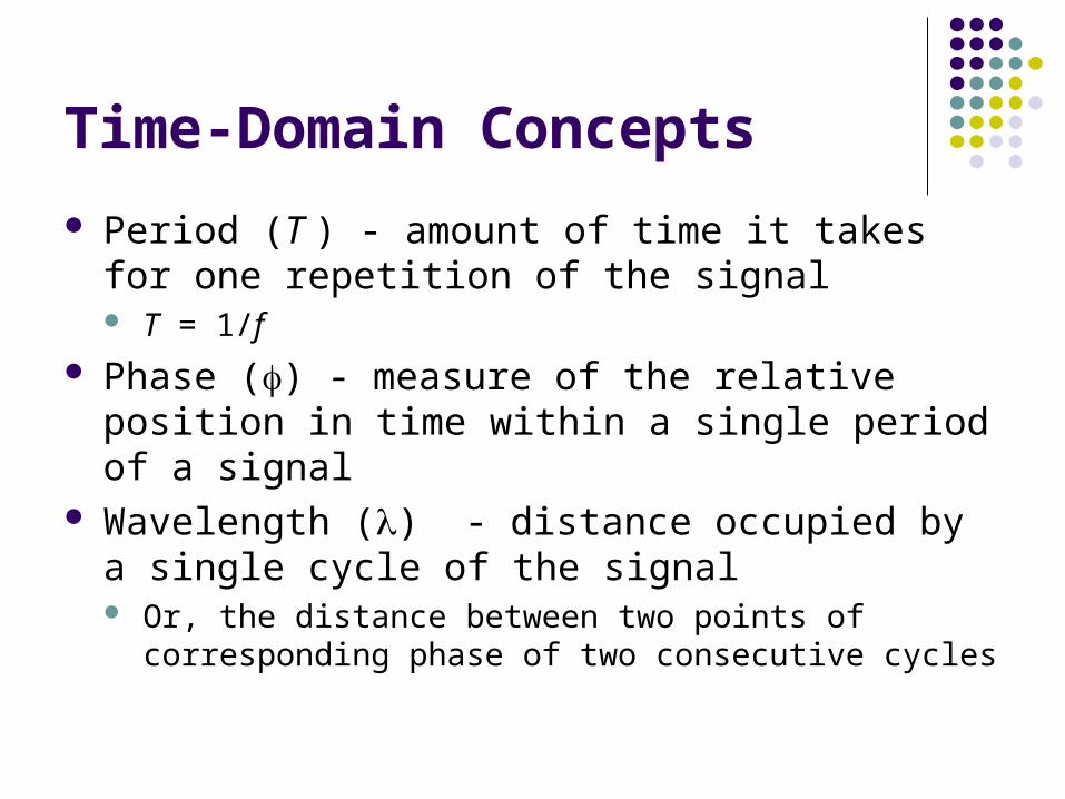
Period (T ) - amount of time it takes for one repetition of the signal T = 1/f
Phase () - measure of the relative position in time within a single period of a signal
Wavelength () - distance occupied by a single cycle of the signal Or, the distance between two points of corresponding phase of
two consecutive cycles

Sine Wave Parameters
General sine wave s(t ) = A sin(2ft + )
Figure 2.3 shows the effect of varying each of the three parameters (a) A = 1, f = 1 Hz, = 0; thus T = 1s (b) Reduced peak amplitude; A=0.5 (c) Increased frequency; f = 2, thus T = ½ (d) Phase shift; = /4 radians (45 degrees)
note: 2 radians = 360° = 1 period

Sine Wave Parameters
Time vs. Distance
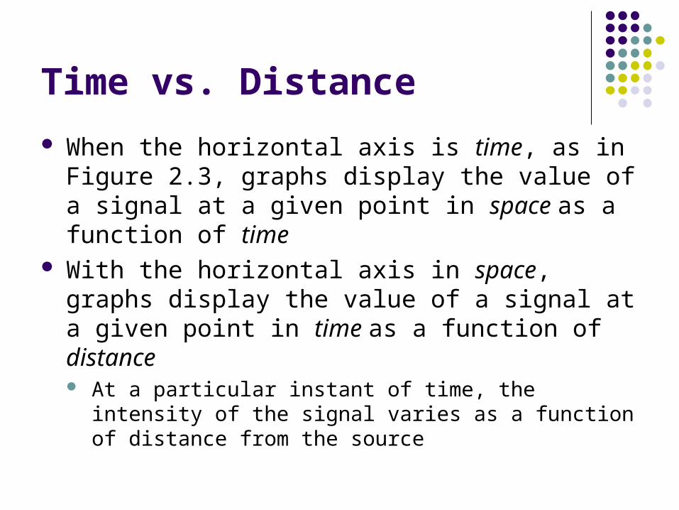
When the horizontal axis is time, as in Figure 2.3, graphs display the value of a signal at a given point in space as a function of time
With the horizontal axis in space, graphs display the value of a signal at a given point in time as a function of distance At a particular instant of time, the intensity of the signal varies as
a function of distance from the source

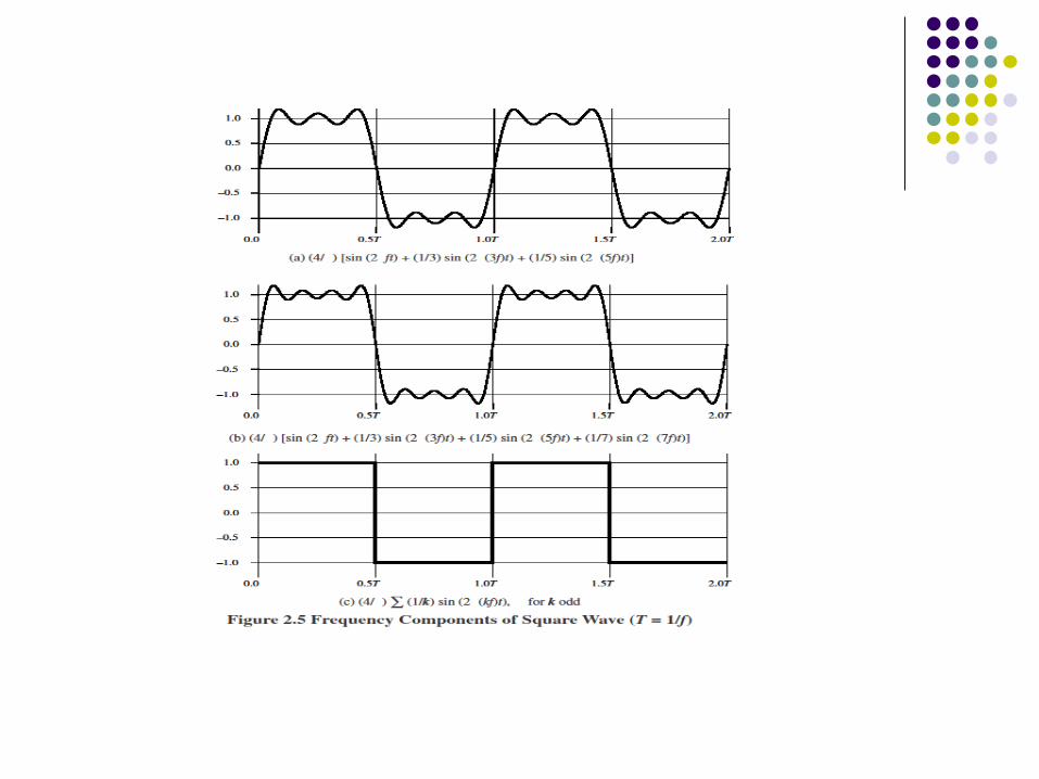
Frequency-Domain Concepts
Fundamental frequency - when all frequency components of a signal are integer multiples of one frequency, it’s referred to as the fundamental frequency
Spectrum - range of frequencies that a signal contains Absolute bandwidth - width of the spectrum of a signal Effective bandwidth (or just bandwidth) - narrow band of
frequencies that most of the signal’s energy is contained in


Frequency-Domain Concepts
Any electromagnetic signal can be shown to consist of a collection of periodic analog signals (sine waves) at different amplitudes, frequencies, and phases
The period of the total signal is equal to the period of the fundamental frequency

Relationship between Data Rate and Bandwidth
The greater the bandwidth, the higher the information-carrying capacity
Conclusions Any digital waveform will have infinite bandwidth BUT the transmission system will limit the bandwidth that can be
transmitted AND, for any given medium, the greater the bandwidth
transmitted, the greater the cost HOWEVER, limiting the bandwidth creates distortions

Data Communication Terms
Data - entities that convey meaning, or information
Signals - electric or electromagnetic representations of data
Transmission - communication of data by the propagation and processing of signals

Examples of Analog and Digital Data
Analog Video Audio
Digital Text Integers

Analog Signals
A continuously varying electromagnetic wave that may be propagated over a variety of media, depending on frequency
Examples of media: Copper wire media (twisted pair and coaxial cable) Fiber optic cable Atmosphere or space propagation
Analog signals can propagate analog and digital data

Digital Signals
A sequence of voltage pulses that may be transmitted over a copper wire medium
Generally cheaper than analog signaling Less susceptible to noise interference Suffer more from attenuation Digital signals can propagate analog and digital
data

Analog Signaling

Digital Signaling

Reasons for Choosing Data and Signal Combinations
Digital data, digital signal Equipment for encoding is less expensive than digital-to-
analog equipment Analog data, digital signal
Conversion permits use of modern digital transmission and switching equipment
Digital data, analog signal Some transmission media will only propagate analog signals Examples include optical fiber and satellite
Analog data, analog signal Analog data easily converted to analog signal

Analog Transmission
Transmit analog signals without regard to content Attenuation limits length of transmission link Cascaded amplifiers boost signal’s energy for
longer distances but cause distortion Analog data can tolerate distortion Introduces errors in digital data

Digital Transmission
Concerned with the content of the signal Attenuation endangers integrity of data Digital Signal
Repeaters achieve greater distance Repeaters recover the signal and retransmit
Analog signal carrying digital data Retransmission device recovers the digital data from analog
signal Generates new, clean analog signal

About Channel Capacity
Impairments, such as noise, limit data rate that can be achieved
For digital data, to what extent do impairments limit data rate?
Channel Capacity – the maximum rate at which data can be transmitted over a given communication path, or channel, under given conditions

Concepts Related to Channel Capacity
Data rate - rate at which data can be communicated (bps) Bandwidth - the bandwidth of the transmitted signal as
constrained by the transmitter and the nature of the transmission medium (Hertz)
Noise - average level of noise over the communications path
Error rate - rate at which errors occur Error = transmit 1 and receive 0; transmit 0 and receive 1

Nyquist Bandwidth
For binary signals (two voltage levels) C = 2B
With multilevel signaling C = 2B log2 M
M = number of discrete signal or voltage levels
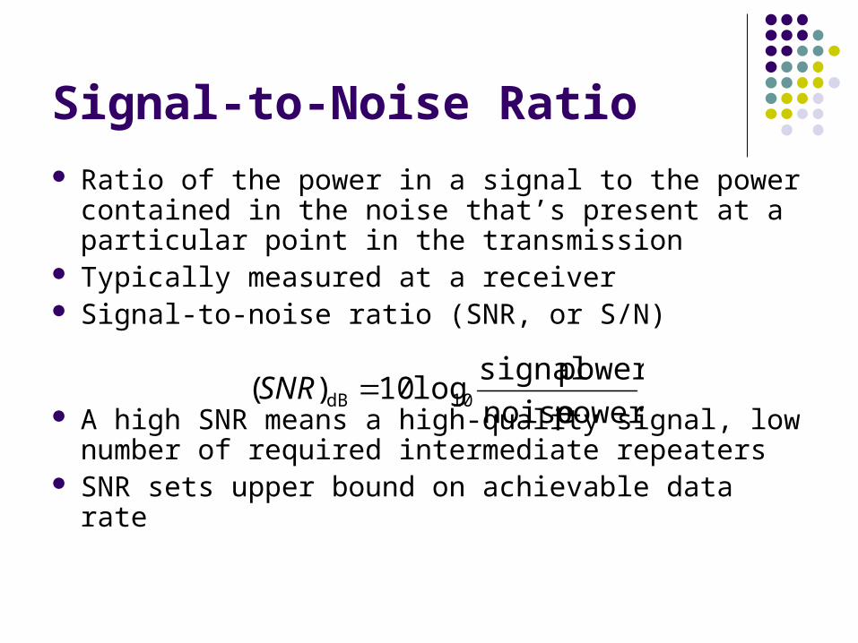
Signal-to-Noise Ratio
Ratio of the power in a signal to the power contained in the noise that’s present at a particular point in the transmission
Typically measured at a receiver Signal-to-noise ratio (SNR, or S/N)
A high SNR means a high-quality signal, low number of required intermediate repeaters
SNR sets upper bound on achievable data rate
power noise
power signallog10)( 10dB SNR

Shannon Capacity Formula
Equation:
Represents theoretical maximum that can be achieved In practice, only much lower rates achieved
Formula assumes white noise (thermal noise) Impulse noise is not accounted for Attenuation distortion or delay distortion not accounted for
SNR1log2 BC

Example of Nyquist and Shannon Formulations
Spectrum of a channel between 3 MHz and 4 MHz ; SNRdB = 24 dB
Using Shannon’s formula
251SNR
SNRlog10dB 24SNR
MHz 1MHz 3MHz 4
10dB
B
Mbps88102511log10 62
6 C

Example of Nyquist and Shannon Formulations
How many signaling levels are required?
16
log4
log102108
log2
2
266
2
M
M
M
MBC

Classifications of Transmission Media
Transmission Medium Physical path between transmitter and receiver
Guided Media Waves are guided along a solid medium E.g., copper twisted pair, copper coaxial cable, optical fiber
Unguided Media Provides means of transmission but does not guide
electromagnetic signals Usually referred to as wireless transmission E.g., atmosphere, outer space

Unguided Media
Transmission and reception are achieved by means of an antenna
Configurations for wireless transmission Directional Omnidirectional
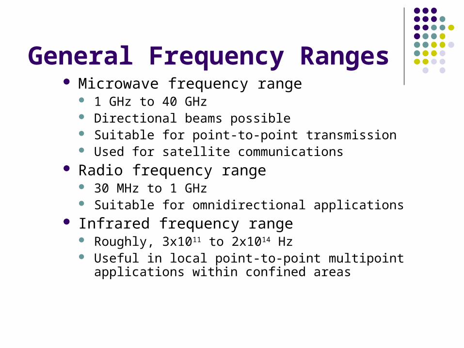
General Frequency Ranges Microwave frequency range
1 GHz to 40 GHz Directional beams possible Suitable for point-to-point transmission Used for satellite communications
Radio frequency range 30 MHz to 1 GHz Suitable for omnidirectional applications
Infrared frequency range Roughly, 3x10¹¹ to 2x10¹⁴ Hz Useful in local point-to-point multipoint applications within
confined areas

Terrestrial Microwave
Description of common microwave antenna Parabolic "dish", 3 m in diameter Fixed rigidly and focuses a narrow beam Achieves line-of-sight transmission to receiving antenna Located at substantial heights above ground level
Applications Long haul telecommunications service Short point-to-point links between buildings

Satellite Microwave
Description of communication satellite Microwave relay station Used to link two or more ground-based microwave
transmitter/receivers Receives transmissions on one frequency band (uplink),
amplifies or repeats the signal, and transmits it on another frequency (downlink)
Applications Television distribution Long-distance telephone transmission Private business networks

Broadcast Radio
Description of broadcast radio antennas Omnidirectional Antennas not required to be dish-shaped Antennas need not be rigidly mounted to a precise alignment
Applications Broadcast radio
VHF and part of the UHF band; 30 MHZ to 1GHz Covers FM radio and UHF and VHF television

Multiplexing
Capacity of transmission medium usually exceeds capacity required for transmission of a single signal
Multiplexing - carrying multiple signals on a single medium More efficient use of transmission medium

Multiplexing

Multiple Access
Multiple Access schemes are used to allow many mobile users to share a finite amount of radio spectrum.
The sharing of spectrum is required to achieve high capacity by simultaneous allocating the bandwidth.
Constraint: there should not be severe performance degradation.

Reasons for Widespread Use of Multiplexing
Cost per kbps of transmission facility declines with an increase in the data rate
Cost of transmission and receiving equipment declines with increased data rate
Most individual data communicating devices require relatively modest data rate support

Multiplexing Techniques
Frequency-division multiplexing (FDM) Takes advantage of the fact that the useful bandwidth
of the medium exceeds the required bandwidth of a given signal
Time-division multiplexing (TDM) Takes advantage of the fact that the achievable bit rate
of the medium exceeds the required data rate of a digital signal

Frequency-division Multiplexing

Time-division Multiplexing
Questions?


