59
Wiring Specifications and Recommendations 7479 REA Rd. • PO Box 168 Oconto Falls, WI 54154 (800) 472-8410 • (920) 846-2816 www.ocontoelectric.com Revised: April 10, 2017

Wiring Specifications and
Recommendations
7479 REA Rd. • PO Box 168Oconto Falls, WI 54154
(800) 472-8410 • (920) 846-2816www.ocontoelectric.com
Revised: April 10, 2017
OCONTO ELECTRIC COOPERATIVEWIRING SPECIFICATIONS AND RECOMMENDATIONS
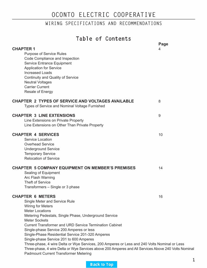
Table of Contents PageCHAPTER 1 4 Purpose of Service Rules Code Compliance and Inspection Service Entrance Equipment Application for Service Increased Loads Continuity and Quality of Service Neutral Voltages Carrier Current Resale of Energy
CHAPTER 2 TYPES OF SERVICE AND VOLTAGES AVAILABLE 8 Types of Service and Nominal Voltage Furnished
CHAPTER 3 LINE EXTENSIONS 9 Line Extensions on Private Property Line Extensions on Other Than Private Property
CHAPTER 4 SERVICES 10 Service Location Overhead Service Underground Service Temporary Service Relocation of Service
CHAPTER 5 COMPANY EQUIPMENT ON MEMBER’S PREMISES 14 Sealing of Equipment Arc Flash Warning Theft of Service Transformers – Single or 3 phase
CHAPTER 6 METERS 16 Single Meter and Service Rule Wiring for Meters Meter Locations Metering Pedestals, Single Phase, Underground Service Meter Sockets Current Transformer and URD Service Termination Cabinet Single-phase Service 200 Amperes or less Single-Phase Residential Service 201-320 Amperes Single-phase Service 201 to 600 Amperes Three-phase, 4 wire Delta or Wye Services, 200 Amperes or Less and 240 Volts Nominal or Less Three-phase, 4 wire Delta or Wye Services above 200 Amperes and All Services Above 240 Volts Nominal Padmount Current Transformer Metering
1

OCONTO ELECTRIC COOPERATIVEWIRING SPECIFICATIONS AND RECOMMENDATIONS
Grounding of Current Transformer Cabinets and Instrument Transformer-rated Meter Sockets and Cabinets Grounding at Metering Installations and Service Entrances
CHAPTER 7 MOTORS AND MOTOR REGULATIONS 21 Three Phase Motors
CHAPTER 8 WATER HEATING 22 Continuous Service Water Heating Storage Type Water Heating
CHAPTER 9 ELECTRIC SPACE HEATING 22 CHAPTER 10 RECTIFYING TYPE CONTROLS 23 CHAPTER 11 ELECTRIC WELDERS AND FURNACES 23 CHAPTER 12 MEMBER-OWNED GENERATING EQUIPMENT 23 Standby Generating Equipment Parallel Generation System
CHAPTER 13 MOBILE HOMES & MODULAR HOMES 24 Mobile Homes Modular Homes Single Meter Installation Grouped Meter Installation
CHAPTER 14 LOAD MANAGEMENT & REBATE PROGRAMS 25 Water Heater Program Geothermal Heat Pump Program-Dual Fuel Air Source Heat Pump Program-Dual Fuel Plenum Heater Electric Thermal Storage Program Electric Boiler Program Central Air Conditioning Program
2
OCONTO ELECTRIC COOPERATIVEWIRING SPECIFICATIONS AND RECOMMENDATIONS
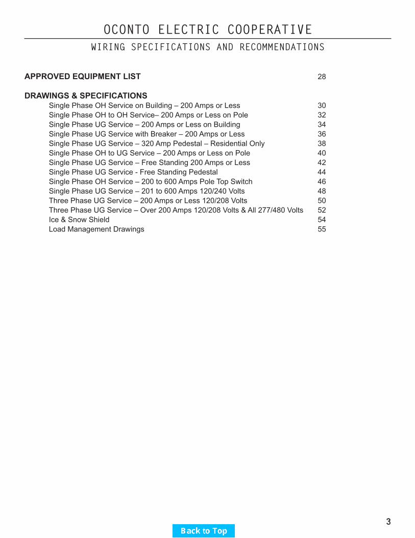
APPROVED EQUIPMENT LIST 28
DRAWINGS & SPECIFICATIONS Single Phase OH Service on Building – 200 Amps or Less 30 Single Phase OH to OH Service– 200 Amps or Less on Pole 32 Single Phase UG Service – 200 Amps or Less on Building 34 Single Phase UG Service with Breaker – 200 Amps or Less 36 Single Phase UG Service – 320 Amp Pedestal – Residential Only 38 Single Phase OH to UG Service – 200 Amps or Less on Pole 40 Single Phase UG Service – Free Standing 200 Amps or Less 42 Single Phase UG Service - Free Standing Pedestal 44 Single Phase OH Service – 200 to 600 Amps Pole Top Switch 46 Single Phase UG Service – 201 to 600 Amps 120/240 Volts 48 Three Phase UG Service – 200 Amps or Less 120/208 Volts 50 Three Phase UG Service – Over 200 Amps 120/208 Volts & All 277/480 Volts 52 Ice & Snow Shield 54 Load Management Drawings 55
3

OCONTO ELECTRIC COOPERATIVEWIRING SPECIFICATIONS AND RECOMMENDATIONS
Chapter 1 – General
Purpose of Service RulesThe following information, detailing the rules and regulations of the Cooperative concerning electric service installations, is published for the convenience of the Cooperative’s members and their architects and contractors. These rules are in addition to the Wisconsin Administrative Code and any other regulations that may apply. The Cooperative reserves the right to make revisions in these rules whenever changes in the art, legal requirements, or other circumstances make it advisable. These rules are intended for standard equipment installations. When, because of physical limitations of the premises, it is impractical to follow them, the Cooperative shall be consulted for permissible modifications. The information contained herein does not specifically cover the requirements of the Cooperative’s rate schedules, line extension policy, or general rules; the Cooperative should be consulted for information concerning these matters.
The Cooperative may refuse or discontinue service if a member does not comply with these rules; however, the member will first be notified and afforded reasonable opportunity to comply. Service may be discontinued without prior notice when dangerous conditions exist on the member’s premises.
Member Wiring – Code Compliance and InspectionAll wiring shall be done in accordance with requirements of the Wisconsin Administrative (electrical) Code, the Cooperative’s rules and other local requirements which may apply.
The Cooperative will not inspect member’s wiring or equipment beyond the metering pedestal or cabinet for compliance with the applicable codes.
In new wiring installations or when changes in existing wiring are made which require the removal of meters or the disconnection of service, the Cooperative shall not connect or resume service until the facility is inspected and approved by a state certified inspector. In some cases where the local jurisdiction does not require inspection for the wiring being done, the contractor or person doing the wiring shall furnish the Cooperative with a written statement (wiring affidavit) indicating that the electrical wiring complies with the Wisconsin Administrative (electrical) Code and the Oconto Electric Cooperative service rules. Wiring affidavit forms are available at the OEC offices or can be downloaded at www.ocontoelectric.com.
Inactive accounts where the meter and service have been removed shall be treated as new wiring when a request for service is received. (See above paragraphs.)
The Cooperative will not interpret the electrical code. Questions concerning code interpretations should be referred to the local or state electrical inspector. The address and phone number is: State of Wisconsin Department of Safety and Professional Services PO Box 7302 Madison, WI 53707-7302 Phone: (608) 264-7823 [email protected]
The Cooperative will inspect for compliance with its rules and may refuse or discontinue electric service if its rules are not complied with or if a hazardous condition exists.
4

OCONTO ELECTRIC COOPERATIVEWIRING SPECIFICATIONS AND RECOMMENDATIONS
Service may be obtained prior to completion of wiring if the service entrance is completed and compliance with Cooperative rules and proof of compliance with applicable codes has been received.
Cooperative crews setting meters or connecting new services for single-phase one-family dwellings test for infinite resistance at the meter socket load terminals. If this check indicates connected load at the load terminals, the meter will not be set. It is recommended that the service disconnect switch be left open to avoid the indication of connected load at the meter base. COOPERATIVE CREWS WILL NOT ENTER A BUILDING TO OPEN OR INSPECT THE SERVICE DISCONNECT SWITCH.
Service Entrance EquipmentA. The member shall own, install, and maintain the service entrance equipment.B. Single-phase service for one and two-family dwellings, 200 Amperes or less, shall have fuses or breakers
installed as part of the service entrance equipment rated a minimum of 22,000 Amperes interrupting capacity. On all other services, consult the Cooperative for maximum available short circuit current.
C. Insulated neutral or grounded conductors of a service entrance shall be identified by a white or natural gray color. Four-wire 120/240 volt Delta installations shall have the conductor with the higher voltage to ground identified with orange over its entire length or shall be identified with orange paint or tape at any point where a connection is to be made.
D. Member owned lightning arresters or other surge protection devices, if used, shall be installed on the load side of the customer’s service overcurrent protective devices, unless specific approval has been received from the Cooperative to install them ahead of the overcurrent protective devices.
Application for ServiceGuidelines for applying for service are outlined below.
A. Application for Initial Service Application for initial service or for a change in existing service Information needed by the member in order to proceed with the installation can be obtained from OEC’s
office or online at www.ocontoelectric.com .B. Site Visit A site visit is necessary to determine the location of the temporary and/or permanent service termination
point. An appointment fee is required before the site visit is scheduled with the staking technician.C. Construction Charges The Staking Technician will calculate the construction charges and an invoice will be sent. All charges
must be paid prior to the installation of the service.D. Member’s Underground Facilities Member will be required to fill out and sign an Underground Service Agreement. This form is available at
OEC’s office or online at www.ocontoelectric.com . (This form shows any private facilities buried that might be in conflict with the proposed new underground service path.)
E. Easements and Government Requirements Easements required from the applicant and from other parties shall be obtained by the applicant at no cost
to the Cooperative. The Cooperative may prepare the easements for the applicant’s signature. Any permits, inspections, surveys, etc, required before construction which require a fee, shall be paid for by the party requesting service.
F. Line Clearance (Tree & Brush Removal) Applicant is responsible for initial clearing of right-of way on applicant’s property as required for line construction.
5

OCONTO ELECTRIC COOPERATIVEWIRING SPECIFICATIONS AND RECOMMENDATIONS
G. Completion of Service Entrance Wiring The service entrance and electrical wiring connected to the service shall be inspected by a state certified
inspector before the installation will be energized. Written notification from the inspector must be received by OEC that the wiring inspected meets the applicable rules before service will be connected. In some cases where the local jurisdiction does not require inspection for the wiring being done, the contractor or person doing the wiring shall furnish the Cooperative with a written statement (wiring affidavit) indicating that the electrical wiring complies with the Wisconsin Administrative (electrical) Code and the Oconto Electric Cooperative service rules. Wiring affidavit forms are available at the OEC offices or can be downloaded at www.ocontoelectric.com .
H. Job Scheduling Prior to job scheduling by the Cooperative, the following items, where applicable, are required:
1. All paperwork and fees have been submitted2. Cable route has been cleared of any brush, dirt piles, and debris3. Electric meter base has been installed and a written inspection report has been received by OEC
from a Wisconsin state certified inspector or, if an inspection is not required, an affidavit has been submitted to OEC by the person doing the electrical work.
4. The foundation wall and/or the area where the underground facilities are to be installed are backfilled to within 6” of final grade
Increased LoadsIn cases where member’s load requirements have changed, necessitating a larger meter or transformer, the Cooperative shall be given reasonable notice so that it may provide a meter, service drop, and transformer of the proper capacity. Delays, poor service or a burned-out meter or transformer will thus be avoided. This applies particularly to members who connect temporary or portable equipment. The Cooperative may charge for the replacement cost of damaged Cooperative equipment.
Continuity and Quality ServiceThe Cooperative will use reasonable care to provide an uninterrupted and regular supply of service; but shall not be liable for any loss, injury, or damage resulting from interruptions, deficiencies or imperfections of service not due to willful default or negligence on its’ part.
The Cooperative shall have the right to cause service to any customer to be interrupted or limited at any time, without liability, by automatic devices or otherwise, when in the judgment of the Cooperative such interruption or limitation is necessary or desirable due to emergency conditions.
All motors, appliances or equipment connected to the Cooperative’s system shall be so designed, installed, and operated as not to cause interference to other Members’ service equipment nor to impede the Cooperative in maintaining proper system conditions.
It shall be the responsibility of the member to provide motor protection for undervoltage, overcurrent, short circuit, loss of a phase, and phase reversal.
The Cooperative may also curtail or temporarily interrupt the member’s electric service in order to make repairs, replacements or changes to the Cooperative’s facilities, either on or off the member’s premises. The Cooperative will, whenever practical, give notice to members who might be seriously affected by such suspension or curtailment of service.
6

OCONTO ELECTRIC COOPERATIVEWIRING SPECIFICATIONS AND RECOMMENDATIONS
It is intended that the voltage provided to the member comply with the requirements of the Wisconsin Administrative Code. This code allows voltage transients of an infrequent nature, which may adversely affect the operation of certain sensitive equipment. Prevention of undesirable operation of sensitive equipment caused by these transients is the responsibility of the member.
Neutral VoltagesIt is normal for the Cooperative’s system neutral to carry low voltage levels, particularly in rural areas. This voltage creates no difficulty for most members. Where a problem is experienced due to this voltage, measures are available to the member to eliminate the problem. Proper grounding of wiring, bonding, and other electrical connections on the member’s premise by the member and his electrician are important factors in mitigating such problems.
Carrier CurrentThe cooperative reserves the right to use carrier frequency signals on its system for communication, system operation, and equipment control and shall not be held liable for potential damages. The member should install suitable protective equipment if such frequencies might damage or interfere with their apparatus. The use by the member of any part of the cooperative’s distribution system for carrying foreign electric currents or for carrier current transmission, broadcasting, or control is forbidden. Members using carrier current or any control frequency other than 60 hertz shall be required to install suitable equipment to prevent these frequencies from being imposed upon or entering the cooperative’s distribution system.
Resale of EnergyService shall be for the member’s use only and may not be sold, re-metered or otherwise disposed of by the member to lessee, tenants or others, except with the consent of the Cooperative in accordance with the Cooperative’s appropriate Rate Schedule permitting such use of service. This does not prohibit the installation of test or check meters for informational purposes.
Including the cost of electric service in the rent without identification as such is permitted.
7

OCONTO ELECTRIC COOPERATIVEWIRING SPECIFICATIONS AND RECOMMENDATIONS
Chapter 2 - Types of Service and Voltages Available
For other than one or two-family dwellings, the Cooperative shall be consulted as to the type of service available in any area before wiring layouts are made, equipment is purchased, or when extensive wiring changes are contemplated.
The Cooperative furnishes 60-Hertz (cycles) alternating current, single and three-phase, at various voltages, but not all types of service are available in every locality.
The type of service available to the member is ordinarily determined by one or more of the following conditions:A. Types of service available at the member’s location.B. Character and size of load to be served.C. Temporary or permanent.D. Underground or overhead service.
The Types of Service and Nominal Voltage FurnishedA. Single-phase, 120/240 volts, three-wire. Maximum 600 AmpB. Three-phase, 480 volts, three-wire. (Limited availability for existing installations; consult Cooperative.)C. Combination single-phase and three-phase, 120/240 volts; four wire Delta. (New installations limited
availability; consult Cooperative.)D. Combination single-phase and three-phase, 120/208 volts, four-wire Wye.E. Combination single-phase and three-phase, 277/480 volts, four-wire Wye.
Electric service at other voltages and capacities may be obtained under special circumstances.
Members’ request for additional services or services which do not conform to these rules shall be treated as “special facilities”. The member is obligated, in accordance with Cooperative extension rules, for any added cost involved. The Cooperative reserves the right to deny special facilities.
8

OCONTO ELECTRIC COOPERATIVEWIRING SPECIFICATIONS AND RECOMMENDATIONS
Chapter 3 – Line Extensions
Line Extensions on Private Property
Extensions of the Cooperative’s distribution lines on to property of the member to be served will be made in accordance with the Cooperative’s extension rules which are available at the Cooperative office. These rules provide, among other things, that the Cooperative will own and be responsible for the maintenance and operation of such lines and shall have the right of access at all reasonable times for construction, reconstruction, tree trimming, maintenance inspection, rebuilding, maintenance and operation of lines and equipment with the right to remove poles and other equipment upon discontinuance of service. The Cooperative shall also be granted the right to extend its facilities to serve other members from such lines.
Oconto Electric Cooperative will prepare all necessary easements along the route selected. The member requesting service shall be responsible for obtaining all signatures and all associated easement costs.Permanent survey stakes identifying property lines may be required by the Cooperative prior to installation of facilities.
When installed at member request, the member shall grant rights-of-way satisfactory to the Cooperative for the installation and maintenance of the electric facilities. The right-of-way as designated by the Cooperative shall be cleared of trees and other obstructions by or at the expense of the member.
The member shall provide grading within six inches of finished grade for the area covered by the right-of-way so that the underground facilities can be properly installed in relation to the finished grade.
Line Extensions on Other than Private Property
The Cooperative shall obtain all licenses or permits that are necessary for right-of-way along routes which are not on private right-of-way. Examples are highway permits, railroad licenses, etc. Associated permit and license fees are the obligation of the member applying for service.
9

OCONTO ELECTRIC COOPERATIVEWIRING SPECIFICATIONS AND RECOMMENDATIONS
Chapter 4 - Services
The Cooperative will extend service to members as promptly as practical consistent with prevailing conditions and will cooperate with contractors and members at all times in order to provide proper service connections. It is requested that application for service be made as early as possible in order to permit the Cooperative to schedule its work. Where there is a question concerning the meaning or application of the Cooperative rules, unnecessary delays or expense may be avoided by consulting the Cooperative in advance of construction. Members, their architects, engineers or contractors shall consult the Cooperative concerning entrance and meter locations; service voltage; the type, phase and voltage of motors and other equipment. They shall consult the Cooperative concerning the installation of special circuits for separate metering or control to meet the rate requirements of the Cooperative and permit adequate service.
Service Location
The location of the member’s service entrance shall in all cases be designated by the Cooperative. The Cooperative or its representatives shall make all connections to its lines, and in no case shall these connections be made by other than Cooperative representatives. To avoid misunderstanding and additional expense, the Cooperative shall be consulted concerning all new service connections.
Disconnecting means shall be provided to disconnect the utility wiring from the premises wiring at any point where utility wiring terminates and premises wiring extends overhead or underground to more than one building or structure. All underground premise wiring shall have disconnecting means and overcurrent protection in accordance with the ampacity of the underground conductors.
Raceways containing unmetered conductors shall not be concealed.
Overhead Service
A. Conductor Clearances In selecting the location of the point of attachment of the service drop, the Cooperative will give careful
consideration to code clearance requirements, location of its supply lines, the needs of the member and the property of others. Overhead service drops from the pole to the member’s point of attachment shall not be greater than 150 feet in length.
The member’s service entrance shall be located so that the Cooperative service wires will not be interfered with by trees and so that buildings and other obstructions are cleared vertically and horizontally in accordance with requirements of the State Electrical Code.
Conductors shall have a clearance of not less than 8 feet from the highest point of roofs over which they pass except as follows:
1. This clearance may be reduced to 3 feet for supply conductors limited to 300 volts to ground and communications conductors and cables if the roof has a 4 / 12 pitch or greater.
2. Where a roof has a 4 / 12 pitch or greater, service drop conductors of 300 volts or less, which do not pass over other than a maximum of 4 feet of the overhang portion of the roof for the purpose of terminating at a through-the-roof service raceway or approved support may be maintained at a
10

OCONTO ELECTRIC COOPERATIVEWIRING SPECIFICATIONS AND RECOMMENDATIONS
minimum of 18 inches from any portion of the roof over which they pass. Overhead service or line conductors:
1. Shall not pass over swimming pools or the surrounding area within 10 feet from the outside edge of the pool or other fixed pool-related structures.
2. Shall not pass over areas where material is regularly stored and handled by cranes or other types of high machinery unless the clearance of the service drop is adequate to permit full use of the equipment.
3. Shall not pass over above-ground flammable liquid or LPG storage tanks (LP gas tanks over 1000 gallon) and the area extending 8 feet horizontally from the tank if the voltage is 300 volts to ground or less, 15 feet horizontally if above 300 volts to ground.
4. Shall not pass over wells within a horizontal distance of not less than ¾ of the required vertical clearance.
B. Service Conductor Termination The Cooperative will provide and the member or contractor shall install the attachment device. The
attachment device shall be installed in a location suitable to permit compliance with clearance requirements and of sufficient strength to support the service drop conductors.
In all cases the member shall be required to extend his service entrance to a sufficient height, not ordinarily exceeding 30 feet, to meet all of the minimum ground clearance requirements for overhead service installation.
If the service attachment on the building cannot be placed at a sufficient height to permit the Cooperative to meet Code ground or other clearance requirements, the member shall provide a support of suitable strength and height to which the service wires can be attached in order to meet the clearance requirements. All such supports shall be durable and of weather resisting material.
Disconnection means shall be provided to disconnect the utility wiring from the premises wiring at any point where the utility wiring terminates and premises wiring extends overhead or underground to more than one building or structure. All underground premises wiring shall also have a disconnecting means and overcurrent protection in accordance with the ampacity of the underground conductor.
If the support is a pole, it shall have a minimum top diameter of 5 inches, treated with an approved preservative a minimum of 6 inches above and 18 inches below the ground line. The pole shall be set a minimum of 5 feet in the ground and guyed.
The member’s service entrance weatherhead shall be installed 6 inches above the designated point of service attachment.
Service entrance conductors shall project at least 30 inches beyond the service head to permit the proper connections to the service wires. The neutral or grounded entrance conductor shall be permanently identified.
11

OCONTO ELECTRIC COOPERATIVEWIRING SPECIFICATIONS AND RECOMMENDATIONS
Underground Service
The Cooperative will install and maintain Cooperative-owned underground electric facilities. Their location, the meter location, and service termination shall be specified by the Cooperative. Underground Extension Rules are available at the Cooperative office or can be downloaded at www.ocontoelectric.com.
A. Member Requirements The member shall identify all privately owned underground equipment on a form provided by Oconto
Electric Cooperative prior to the installation of Cooperative underground electric facilities. Damage to member-owned underground equipment not located and/or identified by the member shall be the member’s responsibility.
The member shall grant tights-of-way satisfactory to the Cooperative for the installation and maintenance of the underground electric facilities.
The member shall provide the following at no expense to the Cooperative:1. The rights-of way shall be cleared of trees and other obstructions.2. Grade within 6” of finished grade of the area covered by the right-of-way so that the underground
facilities can be properly installed in relation to the finished grade.3. Space for underground service conduit riser and conductors shall be clear of obstructions extending
a minimum of 30” below grade.4. Conductors located beneath buildings, pavement, or other obstructions shall be placed in conduit
extending 3 feet beyond the obstruction. If obstructions are placed on the service right-of-way after the service is installed, additional repair costs incurred due to the obstruction will be billed to the member if repairs to the service become needed.
B. Underground Conductor Clearances Underground conductors shall not be installed:
1. Within 5 feet of the inside walls of swimming pools.2. Within 20 feet of fuel storage tanks unless inside of duct supplied or approved by the Cooperative,
the duct to be provided at member’s expense. The duct shall be a continuous piece without splice and shall be of sufficient length to protect the cable for a minimum of 20 feet beyond either side of the fuel tank.
3. Within 10 feet of septic fields, including backup septic field area.4. Within 25 feet of the mound system. The underground conductor cannot be installed between the
tank and the mound because the line between these two is pressurized. Construction equipment shall not travel in the area within 25 feet of the mound system.
Note: The clearance along the sides and the top side could be less. Check with the local county for their requirements.
5. Within one foot of private sewer lines.6. Under areas designated as Class I hazardous locations. (These are areas such as gasoline
dispensing stations.)7. Within five feet of well curbing or casing.
C. Terminating Underground Service Conductors Underground service conductors shall terminate at the metering point. Disconnection means shall be
provided to disconnect the utility wiring from the premises wiring at any point where the utility wiring 12

OCONTO ELECTRIC COOPERATIVEWIRING SPECIFICATIONS AND RECOMMENDATIONS
terminates and premises wiring extends overhead or underground to more than one building or structure. All underground premises wiring shall also have a disconnecting means and overcurrent protection in accordance with the ampacity of the underground conductor.
1. Single-phase or three-phase service, one meter, 200 Amperes or less and 240 volts nominal or less shall terminate at the meter socket line terminals.
2. Single-phase service, one meter, 320 Amperes or less shall terminate at the meter socket line terminals.
3. For single-phase or three-phase multiple socket installations, the member shall provide a single point of termination for Cooperative underground service conductors.
4. Current transformer metering is required on services larger than 200 Amp and services above 240 volts nominal. Current transformers (CT’s) will be installed in, and underground service conductors terminated in, a pre-bussed enclosure approved by the Cooperative and owned, installed, and maintained by the member. The Cooperative shall be consulted for conduit or pedestal location and installation specifications.
5. Conduit risers shall have a sleeve placed around the conduit where the conduit passes through a concrete slab.
6. Soil or ground water conditions generally require the installation of above ground entry of underground service conductors to prevent seepage or water entering through the entrance conduit. The Cooperative will not be responsible for any damage caused by water seeping into the buildings through the member’s raceway or conduit.
7. Ground rods and the grounding conductor shall not be installed within 2 feet of the underground cable route. The grounding shall not be installed in the conduit or pedestal with underground service entrance conductors.
Temporary Service
Temporary service structures shall be adequately supported and of a sufficient height to permit compliance with required Code clearances. The structure, including bracing, shall be clear of the underground service trench route by a minimum of four feet. The installation and removal costs of single-phase temporary services up to 200 Amperes is covered by a single, fixed-fee which applies in most service installations. The temporary should be located as close as practical to an existing overhead transformer pole, or within 6 feet of a padmount transformer.
Relocation of Services
Any change requested by a member in the point of service termination or removal and reinstallation of service conductors will be billed to the member.
13

OCONTO ELECTRIC COOPERATIVEWIRING SPECIFICATIONS AND RECOMMENDATIONS
CHAPTER 5 - Cooperative Equipment on Member’s Premises
The Cooperative shall have the right to install, inspect and maintain its equipment on the member’s premises as is necessary to furnish proper service. All such equipment shall remain Cooperative property, and the Cooperative shall have the right to remove it on discontinuance of service. The member shall be responsible for damages and losses resulting from interference or tampering with such equipment caused or permitted by the member. In the event that the Cooperative equipment is interfered with or damaged, the Cooperative may require the member to change his wiring, at his own expense, to permit the installation of other Cooperative equipment or to permit the relocation of Cooperative equipment to avoid further interference or damage.
Sealing of Equipment
Meters and all associated metering equipment, service termination boxes, wire raceway, and service entrance switches containing unmetered conductors are sealed by the Cooperative. This equipment must be designed with provisions for seals or locks as specified by the Cooperative.
Unauthorized removing of Cooperative seals is unlawful and may result in a billing for the investigation and replacement of the seal as well as criminal prosecution.
Members and/or their electricians are not permitted to pull electric meters. Removing the electric meter will not disconnect service in all cases. Electric meters are not designed or intended for use as a switch to disconnect power to a facility. The potential for serious injury exists when removing or re-installing electric meters. Broken meter socket parts, defective bypass switches, accidental shorts, damage from lightning, disconnecting under heavy load or fault conditions, reconnecting on a fault or high load condition are common problems that can be encountered. If an arc occurs, a very large amount of heat is generated. The heat can explode the meter cover, subject the individual removing or installing the meter to arc flash, and result in electrical contact.
The Cooperative will de-energize the electrical feed to the service entrance equipment if there is a need to work on the equipment.
Arc Flash WARNING
Cooperative electrical facilities have the potential to deliver very high levels of energy during an arc flash incident, potentially causing severe injury or death. Follow the appropriate requirements of OSHA and NFPA-70E if exposed to energized parts of electrical service entrance equipment and electrical metering.
Theft of Service
The Cooperative will investigate for the possibility of theft of service whenever tampering with meter seals, meters, service conductors, and service connections is reported or detected. Only Cooperative authorized persons are permitted to make connections to Cooperative lines.
If the investigation determines that electricity is being stolen, the service may be disconnected.
14

OCONTO ELECTRIC COOPERATIVEWIRING SPECIFICATIONS AND RECOMMENDATIONS
Prior to restoration of service the member’s service entrance equipment shall be made tamper resistant in accordance with Cooperative requirements and satisfactory arrangements will have been made for payment of the estimated amount of unmetered electricity.
Theft of service may result in criminal prosecution.
Transformers – Single or Three Phase
For Cooperative-owned padmount transformer settings, the member shall provide according to Cooperative specification the necessary space, grading, fill, crushed stone, equipment, any formed structured foundations or formed transformer pad, protective barriers or fences, and window barriers at no cost to the Cooperative. The Cooperative shall furnish any preformed transformer pads if required.
15

OCONTO ELECTRIC COOPERATIVEWIRING SPECIFICATIONS AND RECOMMENDATIONS
Chapter 6 - Meters
Single Meter and Service Rules
The Cooperative will normally supply to each member’s building structure or premises:A. One service lateral (drop)B. One class of serviceC. One meter
Exceptions to this rule are:A. Multiple occupancy buildings which comply with the Wisconsin State Electrical Code by having areas under
different occupancies separated by approved firewalls may be supplied by more than one service.B. Fire pumps or other emergency electrical systems requiring separate service.C. Where more than one point of delivery or more than one point of metering is necessary because of
interruptible service rate, governmental requirements or regulatory rules.
Wiring for Meters
The Cooperative will under no circumstances permit “Jumpers” to be placed in meter sockets, which results in unbilled energy.
Metered and unmetered conductors shall not be installed in the same conduit or raceway.
On group installations each service switch, breaker, meter pedestal socket or cabinet shall bear a distinctive, permanent marking clearly identifying the location to be served. The location being served shall be identified in the same manner.
The Cooperative shall not permit meters or instruments other than its own to be connected to its meter wiring.
Meter Locations
Members shall provide a suitable location for meters and associated equipment determined by and without charge to the Cooperative.
Meters shall be installed in an accessible location to enable them to be safely read, inspected and tested at reasonable times with a minimum of inconvenience to the member and Cooperative.
Multiple meter installations served from a single entrance shall be grouped at a location approved by the Cooperative.
All single-phase and polyphase meter installations shall be located out of doors.
Meters shall not be installed in patio, porch, deck or carport areas or areas likely to be enclosed.
At earth bermed buildings that do not have an exposed side suitable for the meter location, the service shall be
16

OCONTO ELECTRIC COOPERATIVEWIRING SPECIFICATIONS AND RECOMMENDATIONS
terminated at a meter pedestal.
Meters shall not be installed on mobile homes. (Please see Chapter 13)
The meter location shall be on a solid structure free from vibration and possible mechanical damage.
The member shall be responsible for providing protection for the meter(s) from damage caused by falling ice, snow or other objects. In locations where the meter is not protected by roof overhang, the member shall provide a protective shield. See “Meter Ice and Snow Shield Guide”.
The clear working space in front of meter panels shall be a minimum of 4 feet and a vertical clearance of 6 feet 6 inches. Two feet of horizontal clearance on either side shall also be provided. Free space in front of instrument transformer cabinets shall be 2 feet beyond the cover in the extended position or a minimum of 4 feet whichever is greater.
If changes are made on the member’s premises making the existing meter location unsafe or inaccessible for reading and testing, the member shall be required to make changes in the wiring so that the meter may be located to comply with these rules. Failure of the member to correct his wiring within a reasonable length of time after written notification shall be considered as noncompliance with these rules. The Cooperative reserves the right to discontinue electric service until the member has changed his wiring as outlined above.
Metering Pedestals - Single-Phase and Three-Phase, Underground Service 240 Volts Nominal or Less
Meter pedestals shall be furnished, installed and maintained by the member.
Pedestal style meter sockets shall be required for services through 200 Amperes. This includes up to four-meter positions. Minimum rating of 200 Amperes is required. Pedestal style single-meter sockets up to 320 Amperes single-phase may be used with cooperative approval for residential services. All 320 Ampere pedestals shall be equipped with a manual bypass so designed that a visual check of the bypass connections can be made with the meter in its installed position. The bypass shall be so designed that when in operation, the socket cover cannot be closed.
Metering pedestals shall be adequately supported to maintain the meter socket in a level and plumb position.
On group installations each meter socket and service switch shall be permanently marked identifying the location to be served. The location being served shall be identified in the same manner.
Metering pedestals shall meet Cooperative and applicable Code requirements.
17

OCONTO ELECTRIC COOPERATIVEWIRING SPECIFICATIONS AND RECOMMENDATIONS
Meter Sockets
Meter sockets shall be furnished, installed and maintained by the member. Pedestal type metering shall be used for all underground services 320 amps and below.
Meter sockets shall be installed in a level and plumb position securely attached to a solid backing.
Single-phase meter sockets 200 Amperes or less shall be equipped with a horn-type bypass or manual bypass so designed that a visual check of the bypass connections can be made with the meter in its installed position. Manual bypasses shall be so designed that when in operation, the socket cover cannot be closed.
Meter sockets shall have connectors suitable for aluminum or copper conductors.
Corrosion inhibitor shall be used on all connections to aluminum conductors.
Single-phase and three-phase meter sockets shall be installed so that the center of the meter shall be not more than 5 feet 6 inches or less than 4 feet 0 inches above finish grade for overhead services and not more than 5 feet 6 inches or less than 3 feet 0 inches for underground services.
On group installations the meter sockets shall be the following:A. Bottom meter shall maintain a minimum of 3 feet above finish grade. B. Top meter shall maintain a maximum of 6 feet above the ground. (All measurements are made from the final grade to the center of the electric meter.) Group or ganged
sockets shall have a single point of termination for Cooperative conductors.
Meter sockets shall have a minimum of 4 inches clearance on all sides of the meter socket.
Self-contained polyphase sockets shall have the following provisions:A. 200 Ampere minimum rating, single position.B. The following minimum dimensions for overhead service: Height – 16 inches, Width – 12 ½ inches, Depth – 4 ½ inchesC. Clamp type jawsD. 600 volts minimum ratingE. Manual bypass (not horn type)F. Wrench operated connector tightening deviceG. Protective shield covering the jaws to prevent accidental shorting or grounding.
Contact the Cooperative office for transformer-rated sockets used on polyphase services.
18

OCONTO ELECTRIC COOPERATIVEWIRING SPECIFICATIONS AND RECOMMENDATIONS
Current Transformer and Underground Service Termination Cabinets
The member shall furnish and install all current transformer cabinets and underground service termination cabinets. All cabinets shall be prebussed enclosures approved by the Cooperative. (Please see “Approved Equipment List”)
All cabinets shall be so installed that the top of the cabinet is not more than 90 inches or the bottom not less than 12 inches above permanent grade or platform.
Single-Phase Service 200 Amperes or Less
Meters shall be located out of doors.
Single-phase Residential Service 201 to 320 Amperes (With Cooperative Approval)
Meters shall be located out of doors.
Single-Phase Service 201 to 600 Amperes
Commercial and farm 201 to 600 Ampere services shall use a prebussed current transformer cabinet approved by the Cooperative and shall be located out of doors.
Three-Phase, Three and Four-Wire Delta or Wye Services 240 Volts nominal or less with 200 Amperes or Less Capacity
Meters shall be socket type and located out of doors. Contact the Cooperative office for installation specifications.
Three-Phase, Four-Wire Delta or Wye Services Above 200 Amperes or Above 240 Volts Nominal
On new installations or existing installations of these types that are to be rearranged, the Cooperative shall be consulted for installation specifications. Self contained metering shall not be used on services above 240 volts nominal.
Meter sockets, current transformer cabinets, and underground service termination cabinets shall be furnished and installed by the member.
19

OCONTO ELECTRIC COOPERATIVEWIRING SPECIFICATIONS AND RECOMMENDATIONS
Padmount Current Transformer Metering
Current transformers may be installed in padmount transformers when the following guidelines are met:A. Padmount current transformer metering shall have approval of the Cooperative Engineering Department.B. The padmount transformer shall be located on the property of the member being served and should serve
only that member.C. The member shall own, install and maintain the service.D. The Cooperative will specify the service conductor size (not ampacity) and will provide and install the lugs
for terminating the member’s conductors at the padmount end.E. The member will provide and install a Milbank UC-3889 or UC7449-XL Milbank 13 terminal meter socket.F. If a suitable wall for mounting the meters is not available within 25’ of the pad mount transformer, a
structure of adequate strength for mounting meters shall be provided by the member. Two 4” X 4” I beams or 3” heavy-walled pipe 10’ long with 4 ½’ buried in 8” diameter concrete supports will meet minimum requirements. An alternate support would be two 5 ½” X 5 ½” X 10’ treated wood posts. A PVC schedule 80 conduit, 1 ¼” minimum, shall be provided and installed by the member from the meter socket to the secondary opening in the transformer pad.
G. Location of padmounted transformer, meter, and conduit will be specified by the Cooperative.
Grounding of Current Transformer Cabinets and Instrument Transformer-Rated Meter Sockets and Cabinets
Grounding Methods for Current Transformer CabinetsA. For services with grounded circuit conductor (all 4-wire and 3-wire 240 volt services) a bonding jumper
shall be connected to the grounded phase or neutral conductor and the metal cabinet frame.B. Services without grounded circuit conductor (3-wire, 480 volt) shall have:
1. Bonded metallic service conduit between the service entrance switch and the cabinet.2. A bonding conductor from the service entrance switch ground of ampacity equal to the service
entrance conductors, to the cabinet.3. Two driven electrodes with grounding electrode conductor to meet Wisconsin Administrative
(electrical) Code, the Cooperative’s rules and other local requirements which may apply.
Grounding Methods for Transformer-rated Meter Sockets and Cabinets
A. Bonded metallic conduit between the meter socket or cabinet and the transformer cabinet.B. A #4 copper bonding conductor from the current transformer cabinet equipment ground.C. For pole metering, a #4 copper bonding conductor connected from the pole ground wire to the meter
socket enclosure.
Grounding at Metering Installations and Service Entrances
The grounding electrode conductors from the ground rods shall not be installed in the conduit with cooperative service conductors, nor can it be spliced or terminated in meter sockets or the utility portion of the meter pedestal.
Grounding systems for all electric service entrances will meet cooperative grounding requirements if 2 ground
20

OCONTO ELECTRIC COOPERATIVEWIRING SPECIFICATIONS AND RECOMMENDATIONS
Chapter 7 - Motors and Motor Regulations
All motor equipment connected to the Cooperative’s system is subject to approval by the Cooperative with respect to starting characteristics and frequency of starts. The Cooperative shall be consulted before installation of motors larger than 10 hp.
Motor installations including starting devices, if necessary, shall be required to have starting characteristics which will not cause an instantaneous voltage drop to other members’ service nor cause objectional lighting flicker.
Installations of motors used to drive equipment requiring a variable torque, such as compressors, reciprocating type pumps, sawmills, etc., shall be required to limit the variation of the motor current so that it will not interfere with service to other members. The Cooperative reserves the right to require the member to provide, at his own expense, equipment to control the fluctuations within limits prescribed by the Cooperative. The maximum allowable variation of motor current for each specific installation may be obtained by contacting the Cooperative.
All member-owned equipment shall be protected from excessive current which may result from overload, undervoltage, single-phase operation of three-phase motor, phase reversal, etc., with fuses, thermal cutouts, overload relays, or other protective devices designed to protect the individual motor. The protective equipment shall be provided by the member.
Three-Phase Motors
Because of varying conditions on the Cooperative system in different locations, it will be necessary to consult the Cooperative in each case to determine the maximum value of starting current, or less, that may be started across the line. Motors with greater starting current may require member equipment to limit the starting current.
At a location where three-phase service is being used and approval has been given for specific motors or motors with starting equipment, other equipment may be installed without further approval as to starting provided that the starting, duty and frequency is no more severe than existing motors. Additional load which will increase the maximum load by 25% or more over a present authorization shall be approved by the Cooperative. This will permit the Cooperative to arrange for proper transformer capacity.
To safeguard the installation, it shall be the responsibility of the member to provide motors with protective and control equipment such as protection against low voltage, overcurrent, phase failure, short circuit, and against phase reversal where reverse operation of a three-phase motor may cause injury or damage.
rods are installed at least 8 feet apart. (There are other variations of grounding systems as described in the Wisconsin Electrical Code SPS 316 and NEC 250 Section III. These can be connected in addition to the ground rods if desired, but will not be accepted in place of the ground rods.)
Ground rods and grounding electrode conductors shall not be located in front of meter pedestals, wire troughs or within 2 feet of underground cable route.
21

OCONTO ELECTRIC COOPERATIVEWIRING SPECIFICATIONS AND RECOMMENDATIONS
Chapter 8 - Water Heating
The member shall consult the Cooperative for correct application of available rates and for assistance in determining which method of installation is desired before wiring layouts are made or equipment is purchased.
Electric water heaters may be connected to the farm, residential and small commercial rates or to the dual fuel & electric thermal storage rate.
Electric water heaters shall be installed in accordance with local and state plumbing and electrical codes.
Continuous Service Water Heating
Electric water heaters may be connected to the general service meter under the residential, farm or small commercial rate in the Cooperative’s service area. Monthly credits to the energy bill are available when these water heaters are permitted to be controlled during hours of peak demand for electricity. Contact the Cooperative office for details.
Water heaters may be connected to 120 volts or 240 volts service. Single phase water heaters shall be equipped with thermostatically controlled noninductive heating elements. The maximum allowable wattage of the element is 1650 watts at 120 volts or 5500 watts at 240 volts. Water heaters having dual elements shall have them connected or interlocked to limit the connected load to the above limits.
Nonstorage, instant recovery water heaters with wattages above 5500 watts may cause service interference. Consult with the Cooperative office before installation.
Storage Type Space Heating and Cooling
Electric water heaters may be connected to the dual fuel/electric thermal storage rate. Contact the Cooperative office for installation specifications.
Chapter 9 - Electric Space Heating
Electric space heating equipment may be connected to the general service meter under the residential, farm or commercial rates. The Cooperative shall be contacted prior to the installation of electric space heating to review the installation and to assure proper transformer capacity and application of rates.
Permanently installed electric space heating designed to operate at 120 volts shall be limited to 1650 watts controlled by a single thermostat. Electric space heating designed to operate at 208 volts and above shall be limited to 6000 watts an element. Multiple elements installed in or as part of a unit exceeding 6000 watts shall be energized in stages not to exceed 6000 watts a stage and at time intervals of not less than three seconds between each stage.
Storage type space heating equipment may be installed and connected to a special off-peak service. Contact the Cooperative office for installation specifications.22

OCONTO ELECTRIC COOPERATIVEWIRING SPECIFICATIONS AND RECOMMENDATIONS
Chapter 10 – Rectifying Type Controls
Speed or energy controls using rectifiers or other devices which cause wave form distortion shall be approved by the Cooperative prior to installation. Members utilizing such devices shall provide adequate filtering or isolating equipment to prevent interference with service provided by the Cooperative.
Chapter 11 – Electric Welders and Furnaces
The consent of the Cooperative shall be obtained, and any changes in the member’s wiring and in the Cooperative’s facilities necessary to permit welder operation under safe conditions and without interference to the service of other members shall be completed before any electric welder is connected.
Chapter 12 – Member-Owned Generating Equipment
Standby Generating Equipment
The Cooperative shall be consulted before any generating equipment is connected to any circuits which are or may be supplied from Cooperative’s service lines.
The member shall install an approved double throw switch or throwover switches that are mechanically interlocked, are of adequate current and voltage rating and are so connected that the member’s generating equipment cannot energize the Cooperative’s supply lines.
The double-throw or throw-over switch may be manually or automatically operated. Member-owned generating equipment shall not operate in parallel with the Cooperative’s system except under specific contract with the Cooperative covering the conditions of such operation.
Parallel Generation System
A parallel generation system allows the transfer of electrical energy from the member’s generator to the Cooperative’s distribution system. Consult the Cooperative for the rules and requirements of this service.
23

OCONTO ELECTRIC COOPERATIVEWIRING SPECIFICATIONS AND RECOMMENDATIONS
CHAPTER 13 – Mobile Homes vs. Modular Homes
Mobile Homes
A mobile home is defined as a factory-assembled structure or structures equipped with the necessary service connections and made so as to be readily movable as a unit or units on its own running gear and designed to be used as a dwelling unit without a permanent foundation. A mobile home is identified with a red metal rectangular label affixed to the rear of each full or half unit. Permanent foundations and permanently connected water and sewer facilities do not change the definition of a mobile home or the rules governing the electric service entrance requirements.
The member shall consult the Cooperative before such an installation is planned or started. The mobile home pedestal or pole shall be located adjacent to the mobile home (no closer than three feet) and not mounted on or in the mobile home.
The service equipment containing the disconnecting means, overcurrent protective devices and receptacles or other approved means for connecting a mobile home service, shall be located in sight of and not more than 30 feet from the exterior wall and not mounted in or on the mobile home. A minimum 100 amp service is required, however for underground service, the meter socket or pedestal must be 200 amp.
The pole or pedestal shall be installed to the prescribed depth, back-filled, and tamped to assure that the fixture remains plumb and the electric meter shall be positioned to face away from the mobile home and preferably face the driveway or road.
Oconto Electric will provide and install a pole for the service entrance if requested by the member. This will be done for a fee to the member, and that will be calculated at the current pricing structure at the time of installation.
Modular Homes
A modular home will be identified with a red plastic seal called a “Wisconsin Insignia” shaped in the outline of the state of Wisconsin. It will usually be affixed to the electrical panel, vanity base cabinet or kitchen cabinet. A modular home as defined by the Uniform Dwelling Code can have the meter pedestal affixed to the dwelling.
Single Meter Installation
The Cooperative shall own and install the service conductors and the meter.
Grouped Meter Installation
The member shall own and install the service pedestal which shall include overcurrent protection and service disconnecting means. Each service switch, breaker, or meter socket shall bear a distinctive, permanent marking clearly identifying the location to be served.
24

OCONTO ELECTRIC COOPERATIVEWIRING SPECIFICATIONS AND RECOMMENDATIONS
Chapter 14 – Load Management
Load Management
Load Management is the intelligent use of electricity by reducing consumption when electric demand is high…and making use of it when demand is low.
Oconto Electric Cooperative offers members the opportunity to take part in load management programs for installing electric water heaters, space heating equipment, central heating/cooling equipment, electric plenum heaters and electric boilers. The programs associated with these products are outlined on the following pages.
For more specific details please contact Oconto Electric Cooperative.
All programs are subject to change at the discretion of the Board of Directors and Management.
Water Heater Program
Oconto Electric Cooperative’s most popular load management program allows the cooperative to shut off electric water heaters during periods of high electric demand. By having an energy efficient Marathon water heater, the member gets the best value for his/her money.
Rebates may be available on certain models of Marathon water heaters. Call OEC for current pricing.
Program Information:• Water heater will be delivered at no charge.• Installation of the heater is the responsibility of the member.• Load management switch will be installed by OEC technician.• Switch must remain on the water heater for a minimum of 5 years.• Member will receive a monthly credit on their electric bill provided usage is over 400 kilowatt-hours in
that month.• OEC reserves the right to periodically inspect the load management switch.
Contact the cooperative if a member wishes to place his/her existing electric water heater on the load management program.
Geothermal Heat Pump Program-Dual Fuel
Oconto Electric Cooperative members who install a Geothermal Heat Pump (GHP) with an automatic, fossil fuel or thermal storage heat source are eligible to utilize the cooperative’s dual fuel rate for the GHP.
A load management switch on the GHP allows the coop to shut off the heat pump during times of high electric demand. It is during those periods that the backup fuel source must begin to operate automatically. (Wood heat is NOT considered an automatic backup.)
A dual fuel metering package must be installed by members’ electrical contractor. An appointment must
25

OCONTO ELECTRIC COOPERATIVEWIRING SPECIFICATIONS AND RECOMMENDATIONS
be scheduled for an OEC technician to install the dual fuel meter and complete the final inspection of the geothermal installation.
Air Source Heat Pump Program-Dual Fuel
An Air Source Heat Pump (ASHP) is another extremely efficient way for a person to heat and cool their home. When heating, an ASHP takes heat from outside air, condenses it, and distributes it throughout the home. These units are ideal when used in conjunction with a plenum heater (see below). When the temperature outside is too low for the heat pump to provide enough heat, the plenum heater adds enough heat to meet the home’s heating requirements.
For cooling the ASHP takes the heat and humidity out of home and disburses it outside, the way central air conditioning does. An OEC technician will install a switch on the heat pump which will allow the cooperative to shut off the heat pump during times of high electric demand. When the cooperative controls heating, the heat pump will be shut off during the high demand period and the fossil fuel must automatically take over. For cooling, the unit will be allowed to cycle on and off at approximate 20-30 minute intervals so the unit is cooling for half of the time.
An Air Source Heat Pump will be eligible for the dual fuel rate if it is used for heating in conjunction with an automatic, fossil fuel or thermal storage backup. A special metering package is required and can be purchased through Oconto Electric.
Plenum Heater
Plenum heaters are installed into the supply air plenum of a forced-air furnace. Electricity is used to heat the plenum heater coils and the warm air is distributed by the furnace fan. The existing furnace may be natural gas, propane or fuel oil. Electricity used for the plenum heater is eligible for the Dual Fuel and Electric Thermal Storage rate.
A special metering package is required and can be purchased through Oconto Electric.
Electric Thermal Storage Program
Electric Thermal Storage (ETS) heating is an option which allows the member to utilize the Dual Fuel and Electric Thermal Storage rate. Thermal storage may in the form of individual room units, a centrally ducted, forced air furnace or hydronic in-floor heat. During off-peak times, heat is stored in a high-density brick core. This stored heat is delivered to the home during on-peak times when OEC controls electric heating load. A consistent room temperature can be maintained for up to 16 hours.
All types of ETS units need a metering package which is purchased from OEC to be eligible for the dual fuel rate.
26
OCONTO ELECTRIC COOPERATIVEWIRING SPECIFICATIONS AND RECOMMENDATIONS
Electric Boiler Program
Electric boilers generate heat that is distributed via radiant floor systems or hydronic baseboards. An automatic fossil fuel or thermal storage backup is required to be eligible for the dual fuel rate. (Wood heat is NOT considered an automatic backup.) When eligibility requirements are met, the electric boiler is metered on the dual fuel rate. A special metering package is required and can be purchased through Oconto Electric.
Central Air Conditioning Program
OEC would like to be able to manage all central air conditioning load. A technician will install a switch on the unit which will allow the cooperative to shut the AC off during times of high electric demand. When the cooperative controls cooling, the unit will be allowed to cycle on and off at approximate 20-30 minute intervals. Members will receive a monthly credit on their electric bills for the months of June, July, August and September consumption.
27

OCONTO ELECTRIC COOPERATIVEWIRING SPECIFICATIONS AND RECOMMENDATIONS
APPROVED EQUIPMENT LIST
100-200 Ampere, Single-phase, Overhead Socket must be UL listed, 100 amp minimum, ringless style, with manual bypass horns
200 Ampere, Single-phase meter pedestal catalog numbers
Manufacturer Single Position Duplex Position Extension Siemens (L & G) UAP317-PPWI 5007718Murray RP118SW UXO78BMilbank U3358-O-KK U1783-O-KK K4695Milbank w/breaker NU8980-0-KK Square D (Durham) UHTRP2423-63-SQDMidwest R2EMSSP6 EK129CW Milbank U4329-O (Joint use pedestal for Telephone, CATV & Electric)
320 Ampere, Single-phase (Residential use by Cooperative approval only)
Manufacturer Single Position Duplex Position Extension Milbank U1748-0-WI S1848Cutler Hammer 1009018CH 1009023
Current Transformer Enclosures for Overhead & Underground Services Above 200 Amperes and All 277/480 Volt Services
Rating Mfg. Overhead Service Underground Service 400 amp/3 wire RJB WPS-403 WPS-403UG 400 amp/3 wire RJB WE-403-6 WE-403-6UG400 amp/3 wire Erickson 1182-1 WPS400 amp/4 wire RJB WPS-404 WPS-404UG 400 amp/4 wire RJB WE-404-13 WE-404-13UG400 amp/4 wire Erickson 1182-2 WPS600 amp/3 wire RJB WPS-603 WPS-603UG 600 amp/3 wire RJB WE-603-6 WE-603-6UG600 amp/3 wire Erickson 1076-1 WPS-LE600 amp/4 wire RJB WPS-604 WPS-604UG 600 amp/4 wire RJB WE-604-13 WE-604-13UG600 amp/4 wire Erickson 1076-2 WPS-LE800 amp/4 wire RJB WPS-804 WPS-804UG 800 amp/4 wire RJB WE-804-13 WE-804-13UG800 amp/4 wire Erickson 1076-2 WPS-LE
28
OCONTO ELECTRIC COOPERATIVEWIRING SPECIFICATIONS AND RECOMMENDATIONS
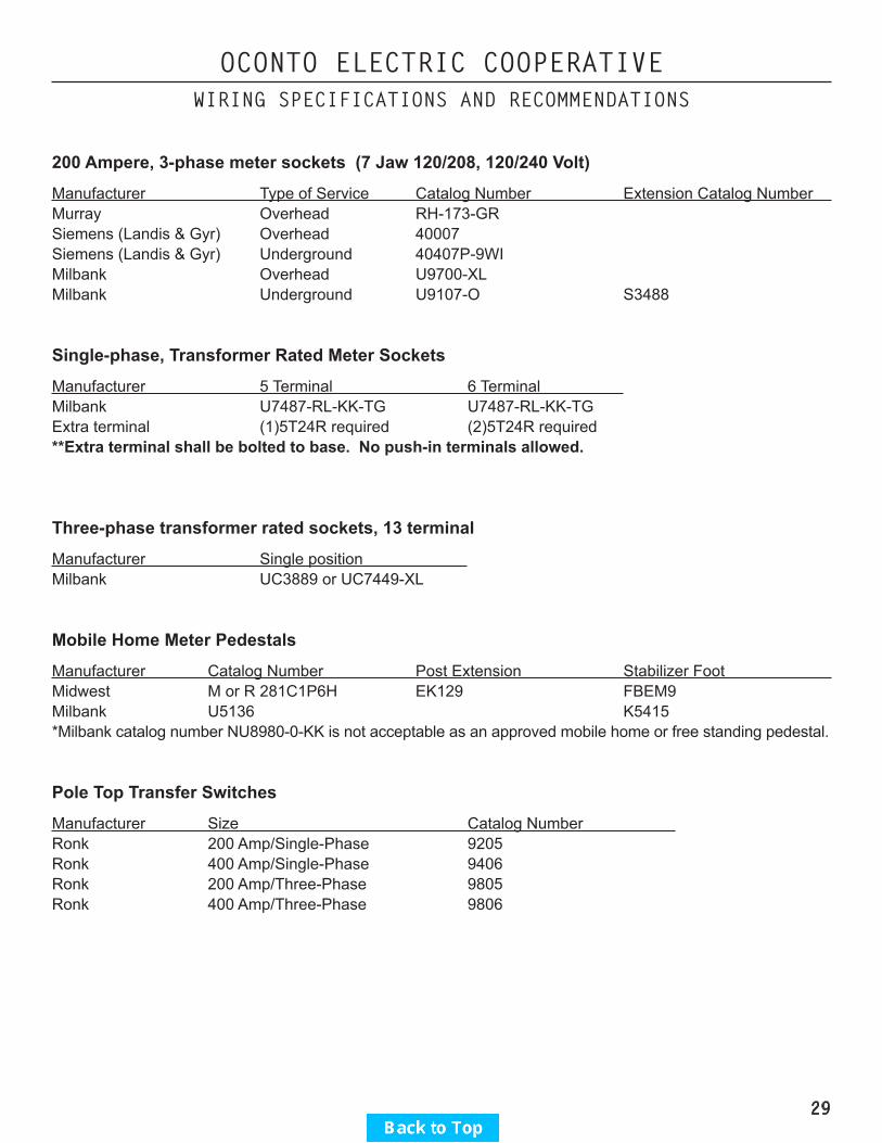
200 Ampere, 3-phase meter sockets (7 Jaw 120/208, 120/240 Volt)
Manufacturer Type of Service Catalog Number Extension Catalog Number Murray Overhead RH-173-GRSiemens (Landis & Gyr) Overhead 40007Siemens (Landis & Gyr) Underground 40407P-9WIMilbank Overhead U9700-XLMilbank Underground U9107-O S3488
Single-phase, Transformer Rated Meter Sockets
Manufacturer 5 Terminal 6 Terminal Milbank U7487-RL-KK-TG U7487-RL-KK-TGExtra terminal (1)5T24R required (2)5T24R required**Extra terminal shall be bolted to base. No push-in terminals allowed.
Three-phase transformer rated sockets, 13 terminal
Manufacturer Single position Milbank UC3889 or UC7449-XL
Mobile Home Meter Pedestals
Manufacturer Catalog Number Post Extension Stabilizer Foot Midwest M or R 281C1P6H EK129 FBEM9Milbank U5136 K5415*Milbank catalog number NU8980-0-KK is not acceptable as an approved mobile home or free standing pedestal.
Pole Top Transfer Switches
Manufacturer Size Catalog Number Ronk 200 Amp/Single-Phase 9205Ronk 400 Amp/Single-Phase 9406Ronk 200 Amp/Three-Phase 9805Ronk 400 Amp/Three-Phase 9806
29

OCONTO ELECTRIC COOPERATIVEWIRING SPECIFICATIONS AND RECOMMENDATIONS
Revised 4/5/17Single Phase OH Service on Building
200 Amps or LessPage 30 of 58
1. Cooperative shall furnish and install conductors to terminate at service mast.2. Cooperative shall furnish and install connectors to connect the Cooperative’s conductors to the Member’s
conductors. 3. Member shall furnish and supply mast, weatherhead, roof flashing, straps, conductors, and attachment
point. Weatherhead must be at least 6” above the attachment point. The mast shall be minimum 2” rigid steel conduit or steel Intermediate Metal Conduit (IMC). Aluminum and thinwall (EMT) are not acceptable. Cooperative will determine service location and mounting height of mast.
4. All mast type services must be guyed. Member shall furnish and install guy wire and roof attachments as required. No couplings are permitted above the point where the mast conduit enters the roof overhang.
5. Member shall furnish and install a meter socket, as required. Minimum is 100 amp, ringless style, horn or lever bypass, and provision for sealing. Socket must be securely attached to supporting structure.
6. Member shall furnish and install load conductors between the meter socket and the service disconnecting means. Service entrance conductors shall not extend over 8 feet into a building unless overcurrent protection is provided at the outer end.
7. Member shall furnish and install two 5/8” X 8’ copperclad steel ground rods and approved clamps. Ground rods and grounding conductors shall not be installed in front of the meter pedestal. Top of rods should be at least 12” below grade level. (There are other variations of grounding systems as described in the Wisconsin Electrical Code SPS 316 and NEC 250 Section III. These can be connected in addition to the ground rods if desired, but will not be accepted in place of the ground rods.)
8. The grounding electrode conductor from the ground rods shall not be spliced or terminated in the meter socket. Ground wire shall be minimum 4 AWG copper wire.
9. An intersystem bonding termination bar shall be provided external to the meter socket for connection of telephone, cable TV, or other utility grounding conductors.
10. Wiring shall be installed in compliance with state electrical code and any local requirements.
30

OCONTO ELECTRIC COOPERATIVEWIRING SPECIFICATIONS AND RECOMMENDATIONS
Revised 4/5/17Single Phase OH Service on Building
200 Amps or LessPage 31 of 58
31

OCONTO ELECTRIC COOPERATIVEWIRING SPECIFICATIONS AND RECOMMENDATIONS
Revised 4/5/17Single Phase OH to OH Service
200 Amps or Less on PolePage 32 of 58
1. Cooperative can furnish and install 30-foot pole, if requested. (fee applies)2. Cooperative shall furnish and install conductors to terminate at meter pole.3. Cooperative shall furnish and install connectors to connect the Cooperative’s conductors to the Member’s
conductors.4. Member shall furnish and install a meter socket, as required. Minimum is 100 amp, ringless style, horn or
lever bypass, and provision for sealing. Socket must be securely attached to supporting structure.5. Member shall furnish and install separate supply side and load side conduits complete with weatherhead,
straps, and conductors. Service entrance (SE) cable shall not be used on a pole.6. Member shall furnish and install a weatherproof disconnecting means. The disconnecting means shall be
located on the load side of the meter socket.7. Member shall furnish and install two 5/8” X 8’ copperclad steel ground rods with approved clamps. Top
of rods should be at least 12” below grade level. (There are other variations of grounding systems as described in the Wisconsin Electrical Code SPS 316 and NEC 250 Section III. These can be connected in addition to the ground rods if desired, but will not be accepted in place of the ground rods.)
8. The grounding electrode conductor from the ground rods shall not be spliced or terminated in the meter socket. Ground wire shall be minimum 4 AWG copper wire.
9. Wiring shall be installed in compliance with state electrical code and any local requirements.
32

OCONTO ELECTRIC COOPERATIVEWIRING SPECIFICATIONS AND RECOMMENDATIONS
Revised 4/5/17Single Phase OH to OH Service
200 Amps or Less on PolePage 33 of 58
33

OCONTO ELECTRIC COOPERATIVEWIRING SPECIFICATIONS AND RECOMMENDATIONS
Revised 4/5/17Single Phase UG Service
200 Amps or Less on BuildingPage 34 of 58
1. The Cooperative shall furnish and install the line conductors. Where the Cooperative’s wires will be covered by concrete or blacktop, the member shall provide conduit to extend at least 3 feet beyond the edge of the concrete or blacktop.
2. Member shall furnish and install a 200-amp meter pedestal approved by the Cooperative. (See “Approved Equipment List”) Maintain minimum 4” clear space between meter pedestal and adjacent equipment.
3. Member shall furnish and install load conductors between the meter pedestal and the service disconnecting means. Service entrance conductors shall not extend over 8 feet into a building unless overcurrent protection is provided at the outer end.
4. Member shall furnish and install two 5/8” X 8’ copperclad steel ground rods with approved clamps. Top of rods should be at least 12” below final grade level. (There are other variations of grounding systems as described in the Wisconsin Electrical Code SPS 316 and NEC 250 Section III. These can be connected in addition to the ground rods if desired, but will not be accepted in place of the ground rods.) Ground rods and grounding conductors shall not be installed in front of the meter pedestal or within 2 feet of the underground cable route.
5. The grounding electrode conductor from the ground rods shall not be spliced or terminated in the meter socket or utility portion of the pedestal. The grounding electrode conductor shall be accessible outside of and adjacent to the meter pedestal for connection of telephone, cable TV, or other utility grounding conductors. Ground wire shall be minimum 4 AWG copper wire.
6. Adequate space shall be provided for removal of the meter pedestal cover when concrete or blacktop covers the area in front of the meter pedestal.
7. Member shall furnish and install an extension for the pedestal, if required, to provide a minimum of 18” of pedestal below final grade level.
8. Meter pedestal shall not be installed under any windows.9. An intersystem bonding termination bar shall be provided external to the meter socket for connection of
telephone, cable TV, or other utility grounding conductors.10. Wiring shall be installed in compliance with state electrical code and any local requirements.
34

OCONTO ELECTRIC COOPERATIVEWIRING SPECIFICATIONS AND RECOMMENDATIONS
Revised 4/5/17Single Phase UG Service
200 Amps or Less on BuildingPage 35 of 58
35
OCONTO ELECTRIC COOPERATIVEWIRING SPECIFICATIONS AND RECOMMENDATIONS
Revised 4/5/17Single Phase UG Service with Breaker
200 Amps or LessPage 36 of 58
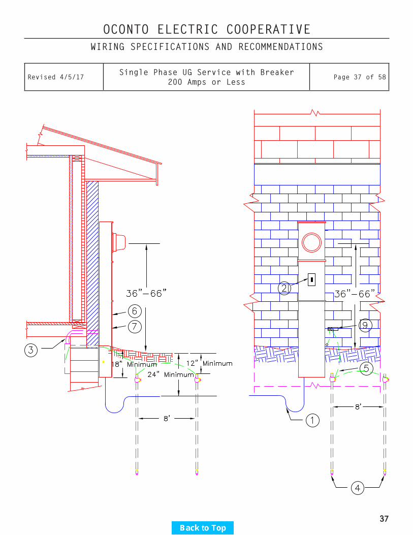
1. The Cooperative shall furnish and install the line conductors. Where the Cooperative’s wires will be covered by concrete or blacktop, the member shall provide conduit to extend at least 3 feet beyond the edge of the concrete or blacktop.
2. Member shall furnish and install a 200 amp meter pedestal with main breaker, approved by the Cooperative. (See “Approved Equipment List”) Maintain minimum 4” clear space between meter pedestal and adjacent equipment.
3. Member shall furnish and install load conductors between the meter pedestal and the breaker panel.4. Member shall furnish and install two 5/8” X 8’ copperclad steel ground rods with approved clamps. Top of
rods should be at least 12” below final grade level. (There are other variations of grounding systems as described in the Wisconsin Electrical Code SPS 316 and NEC 250 Section III. These can be connected in addition to the ground rods if desired, but will not be accepted in place of the ground rods.) Ground rods and grounding conductors shall not be installed in front of the meter pedestal or within 2 feet of the underground cable route.
5. The grounding electrode conductor from the ground rods shall not be spliced or terminated in the meter socket or utility portion of the pedestal. The grounding electrode conductor shall be accessible outside of and adjacent to the meter pedestal for connection of telephone, cable TV, or other utility grounding conductors. Ground wire shall be minimum 4 AWG copper wire.
6. Adequate space shall be provided for removal of the meter pedestal cover when concrete or blacktop covers the area in front of the meter pedestal.
7. Member shall furnish and install an extension for the pedestal, if required, to provide a minimum of 18” of pedestal below final grade level.
8. Meter pedestal shall not be installed under any windows.9. An intersystem bonding termination bar shall be provided external to the meter socket for connection of
telephone, cable TV, or other utility grounding conductors.10. Wiring shall be installed in compliance with state electrical code and any local requirements.
36
OCONTO ELECTRIC COOPERATIVEWIRING SPECIFICATIONS AND RECOMMENDATIONS
Revised 4/5/17Single Phase UG Service with Breaker
200 Amps or LessPage 37 of 58
37

OCONTO ELECTRIC COOPERATIVEWIRING SPECIFICATIONS AND RECOMMENDATIONS
Revised 4/5/17Single Phase UG Service
320 Amp Meter Pedestal-Residential OnlyPage 38 of 58
1. The Cooperative shall furnish and install the line conductors. Where the Cooperative’s wires will be covered by concrete or blacktop, the member shall provide conduit to extend at least 3 feet beyond the edge of the concrete or blacktop.
2. Member shall furnish and install a 320-amp meter pedestal approved by the Cooperative. (See “Approved Equipment List”) Maintain minimum 4” clear space between meter pedestal and adjacent equipment.
3. Member shall furnish and install load conductors between the meter pedestal and the service disconnecting means. Service entrance conductors shall not extend over 8 feet into a building unless overcurrent protection is provided at the outer end.
4. Member shall furnish and install two 5/8” X 8’ copperclad steel ground rods with approved clamps. Top of rods should be at least 12” below final grade level. (There are other variations of grounding systems as described in the Wisconsin Electrical Code SPS 316 and NEC 250 Section III. These can be connected in addition to the ground rods if desired, but will not be accepted in place of the ground rods.) Ground rods and grounding conductors shall not be installed in front of the meter pedestal or within 2 feet of the underground cable route.
5. The grounding electrode conductor from the ground rods shall not be spliced or terminated in the meter socket or utility portion of the pedestal. The grounding electrode conductor shall be accessible outside of and adjacent to the meter pedestal for connection of telephone, cable TV, or other utility grounding conductors. Ground wire shall be minimum 4 AWG copper wire.
6. Adequate space shall be provided for removal of the meter pedestal cover when concrete or blacktop covers the area in front of the meter pedestal.
7. Member shall furnish and install an extension for the pedestal, if required, to provide a minimum of 18” of pedestal below final grade level.
8. Meter pedestal shall not be installed under any windows.9. An intersystem bonding termination bar shall be provided external to the meter socket for connection of
telephone, cable TV, or other utility grounding conductors.10. Wiring shall be installed in compliance with state electrical code and any local requirements.
38

OCONTO ELECTRIC COOPERATIVEWIRING SPECIFICATIONS AND RECOMMENDATIONS
Revised 4/5/17Single Phase UG Service
320 Amp Meter Pedestal-Residential OnlyPage 39 of 58
39

OCONTO ELECTRIC COOPERATIVEWIRING SPECIFICATIONS AND RECOMMENDATIONS
Revised 4/5/17Single Phase OH to UG Service
200 Amps or Less on PolePage 40 of 58
1. Cooperative can furnish and install 30-foot pole, if requested. (fee applies)2. Cooperative shall furnish and install conductors to terminate at meter pole.3. Cooperative shall furnish and install connectors to connect the Cooperative’s conductors to the Member’s
conductors.4. Member shall furnish and install a meter socket, as required. Minimum is 100 amp, ringless style, horn or
lever bypass, and provision for sealing. Socket must be securely attached to supporting structure.5. Member shall furnish and install conduit complete with weatherhead, straps, and conductors. Service
entrance (SE) cable shall not be used on pole.6. Member shall furnish and install a weatherproof disconnecting means. The disconnecting means shall be
located on the load side of the meter socket. *7. Member shall furnish and install two 5/8” X 8’ copperclad steel ground rods with approved clamps. Top of
rods should be at least 12” below final grade level. (There are other variations of grounding systems as described in the Wisconsin Electrical Code SPS 316 and NEC 250 Section III. These can be connected in addition to the ground rods if desired, but will not be accepted in place of the ground rods.)
8. The grounding electrode conductor from the ground rods shall not be spliced or terminated in the meter socket. Ground wire shall be minimum 4 AWG copper wire.
9. Member shall furnish and install the feeder(s) to the loads served. ** 10. Wiring shall be installed in compliance with state electrical code and any local requirements.
*Mobile home service equipment shall be located adjacent to the mobile home with a minimum three-foot separation and not mounted in or on the mobile home. The service equipment or a disconnecting means suitable for use as service equipment shall be located in sight from and not more than 30 feet from the exterior wall of the mobile home it serves.
**For mobile homes, the feeder shall consist of 4 insulated conductors of which one shall be an insulated copper equipment-grounding conductor. The equipment-grounding conductor shall be minimum 6 AWG insulated copper.
40

OCONTO ELECTRIC COOPERATIVEWIRING SPECIFICATIONS AND RECOMMENDATIONS
Revised 4/5/17Single Phase OH to UG Service
200 Amps or Less on PolePage 41 of 58
41
OCONTO ELECTRIC COOPERATIVEWIRING SPECIFICATIONS AND RECOMMENDATIONS
Revised 4/4/17Single Phase UG Service
Free Standing 200 Amps or Less*Page 42 of 58
1. The Cooperative shall furnish and install the underground line conductors. Where the Cooperative’s wires will be covered by concrete or blacktop, the member shall provide conduit to extend at least 3 feet beyond the edge of the concrete or blacktop.
2. Member shall furnish and install a 200 amp meter pedestal (*) approved by the Cooperative. (See “Approved Equipment List”) Maintain minimum 4” clear space between meter pedestal and adjacent equipment.
3. Member shall furnish and install treated posts and backboard or other support structure approved by the Cooperative. Treated wood posts of 6” X 6” nominal dimension and treated planks of 2” X 6” nominal dimension will meet minimum requirements.
4. Member shall furnish and install a weatherproof disconnecting means and all connecting conduits and conductors.(*)
5. Member shall furnish and install two 5/8” X 8’ copperclad steel ground rods with approved clamps. Top of rods should be at least 12” below final grade level. (There are other variations of grounding systems as described in the Wisconsin Electrical Code SPS 316 and NEC 250 Section III. These can be connected in addition to the ground rods if desired, but will not be accepted in place of the ground rods.) Ground rods and grounding conductors shall not be installed in front of the meter pedestal or within 2 feet of the underground cable route.
6. The grounding electrode conductor from the ground rods shall not be spliced or terminated in the meter socket or utility portion of the pedestal. The grounding electrode conductor shall be accessible outside of and adjacent to the meter pedestal for connection of telephone, cable TV, or other utility grounding conductors. Ground wire shall be minimum 4 AWG copper wire.
7. Adequate space shall be provided for removal of the meter pedestal cover when concrete or blacktop covers the area in front of the meter pedestal.
8. Member shall furnish and install an extension for the pedestal, if required, to provide a minimum of 18” of pedestal below final grade level.
9. Member shall furnish and install the feeders to buildings or mobile home. For mobile homes, the feeder shall consist of 4 insulated conductors of which one shall be an insulated copper equipment-grounding conductor. The equipment-grounding conductor shall be minimum 6 AWG insulated copper.
10. Wiring shall be installed in compliance with state electrical code and any local requirements.
*It is also acceptable to use a meter pedestal with the breakers installed in the pedestal. See “Approved Equipment List”.
Mobile home service equipment shall be located adjacent to the mobile home with a minimum three-foot separation and not mounted in or on the mobile home. The service equipment or a disconnecting means suitable for use as service equipment shall be located in sight from and not more than 30 feet from the exterior wall of the mobile home it serves.
42

OCONTO ELECTRIC COOPERATIVEWIRING SPECIFICATIONS AND RECOMMENDATIONS
Revised 4/4/17Single Phase UG Service
Free Standing 200 Amps or Less*Page 43 of 58
43
OCONTO ELECTRIC COOPERATIVEWIRING SPECIFICATIONS AND RECOMMENDATIONS
Revised 4/5/17Single Phase UG Service
Free Standing 200 Pedestal-200 Amps or LessPage 44 of 58
1. The Cooperative shall furnish and install the line conductors. Where the Cooperative’s wires will be covered by concrete or blacktop, the member shall provide conduit to extend at least 3 feet beyond the edge of the concrete or blacktop.
2. Member shall furnish and install a 200 amp meter pedestal approved by the Cooperative. See “Approved Equipment List”. (*)
3. Member shall furnish and install a stabilizer foot approved by the Cooperative. Free standing pedestals require 4”X6” or 6”X6” treated wood post with a minimum of 4’ below ground and 4’ above ground. A 16” long treated wood 2”X6” is required at the base of the wood post. The meter pedestal shall be securely attached to the wood post. The manufactured stabilizer foot is not adequate support for free standing installations.
4. Member shall furnish and install the circuit breaker and all connecting conduits and conductors.5. Member shall furnish and install two 5/8” X 8’ copperclad steel ground rods with approved clamps. Top of
rods should be at least 12” below final grade level. (There are other variations of grounding systems as described in the Wisconsin Electrical Code SPS 316 and NEC 250 Section III. These can be connected in addition to the ground rods if desired, but will not be accepted in place of the ground rods.) Ground rods and grounding conductors shall not be installed in front of the meter pedestal or within 2 feet of the underground cable route.
6. The grounding electrode conductor from the ground rods shall not be spliced or terminated in the meter socket or utility portion of the pedestal. Ground wire shall be minimum 4 AWG copper wire.
7. Adequate space shall be provided for removal of the meter pedestal cover when concrete or blacktop covers the area in front of the meter pedestal.
8. Member shall install pedestal to provide a minimum of 24” of pedestal below final grade level.9. Member shall furnish and install the feeder(s) to buildings or other structures. (**) 10. Wiring shall be installed in compliance with state electrical code and any local requirements.
*Mobile home service equipment shall be located adjacent to the mobile home with a minimum three-foot separation and not mounted in or on the mobile home. The service equipment or a disconnecting means suitable for use as service equipment shall be located in sight from and not more than 30 feet from the exterior wall of the mobile home it serves.
**For mobile homes, the feeder shall consist of 4 insulated conductors of which one shall be an insulated copper equipment-grounding conductor. The equipment-grounding conductor shall be minimum 6 AWG insulated copper.
44
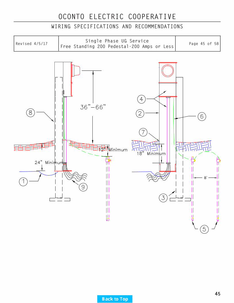
OCONTO ELECTRIC COOPERATIVEWIRING SPECIFICATIONS AND RECOMMENDATIONS
Revised 4/5/17Single Phase UG Service
Free Standing 200 Pedestal-200 Amps or LessPage 45 of 58
45

OCONTO ELECTRIC COOPERATIVEWIRING SPECIFICATIONS AND RECOMMENDATIONS
Revised 4/5/17Single Phase OH Service
200 to 600 Amps Pole Top SwitchPage 46 of 58
1. Cooperative can furnish and install 30-foot pole (fee applies).2. Cooperative shall furnish and install conductors to terminate outside of pole top disconnect. 3. Member shall furnish and install pole top disconnect. Disconnect shall be located a minimum of 15” from
top of pole to top of disconnect enclosure. Pole top disconnect shall have double throw capability for connecting standby generator.
4. Member shall furnish and install insulated conductors terminated in the pole top disconnect and extending 2 feet outside of disconnect enclosure for connection to utility supply conductors.
5. Cooperative shall furnish and install current transformer and metering conductors. 6. Member shall furnish and install a 1” conduit complete with weatherhead and straps, as required, for
metering conductors. Weatherhead to be 12 inches below item #5 location.7. Member shall furnish and install a 100-amp meter socket with 5th terminal in the 9 o’clock position. This
terminal shall be the bolt-in type. No push-in terminals allowed. See “Approved Equipment List”.8. Member shall furnish and install two 5/8” X 8’ copperclad steel ground rods with approved clamps. Top of
rods should be at least 12” below final grade level. (There are other variations of grounding systems as described in the Wisconsin Electrical Code SPS 316 and NEC 250 Section III. These can be connected in addition to the ground rods if desired, but will not be accepted in place of the ground rods.)
9. The grounding electrode conductor from the ground rods shall not be spliced or terminated in the meter socket. Ground wire shall be minimum 4 AWG copper wire.
10. Member shall bond disconnect handle to ground wire.11. Wiring shall be installed in compliance with state electrical code and any local requirements.
46
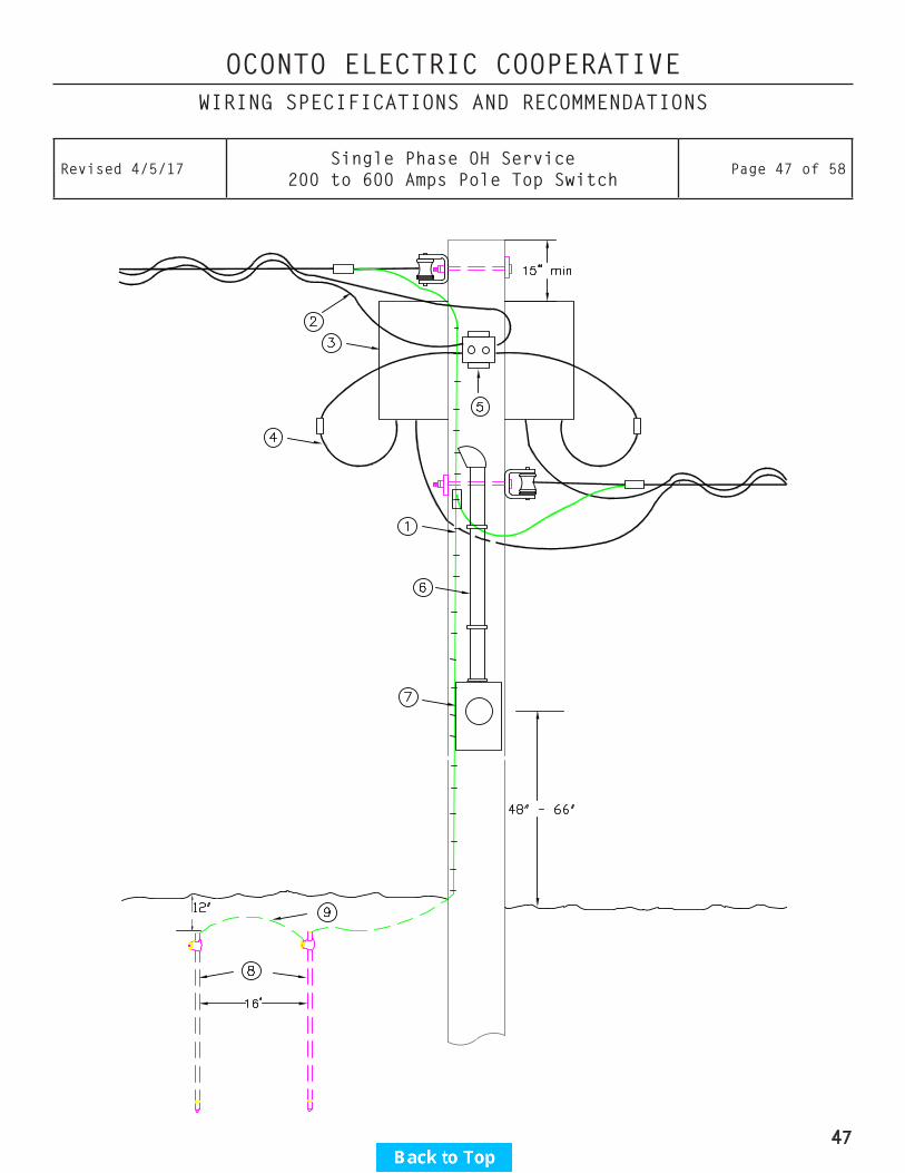
OCONTO ELECTRIC COOPERATIVEWIRING SPECIFICATIONS AND RECOMMENDATIONS
Revised 4/5/17Single Phase OH Service
200 to 600 Amps Pole Top SwitchPage 47 of 58
47

OCONTO ELECTRIC COOPERATIVEWIRING SPECIFICATIONS AND RECOMMENDATIONS
Revised 4/5/17Single Phase UG Service
201-600 Amps 120/240 VoltsPage 48 of 58
1. The Cooperative shall furnish and install the underground line conductors. Where the Cooperative’s wires will be covered by concrete or blacktop, the member shall provide conduit to extend at least 3 feet beyond the edge of the concrete or blacktop.
2. Member shall furnish and install treated posts and backboard or other support structure approved by the Cooperative. Treated wood posts of 6” X 6” nominal dimension and treated planks of 2” X 6” nominal dimension will meet minimum requirements.
3. Member shall furnish and install 3” minimum rigid steel or schedule 80 PVC to extend a minimum of 18” below finished grade.
4. Member shall furnish and install a Cooperative approved current transformer enclosure and all connecting conduit. (See “Approved Equipment List”) Maintain minimum 4” clear space between current transformer enclosure, meter socket, and adjacent equipment.
5. Member shall furnish and install a 100 amp meter socket with two 5th lug terminal kits, one in the 3 o’clock position and one in the 9 o’clock position and a minimum 1” connecting conduit. These terminals shall be the bolt-in type. No push-in terminals allowed.
6. Cooperative shall furnish and install current transformers.7. Cooperative shall furnish and install metering conductors.8. Member shall furnish and install double throw switch (required, if standby generator is used) and service
equipment, as required.9. Member shall furnish and install load conductors and connectors.10. Member shall furnish and install two 5/8” X 8’ copperclad steel ground rods with approved clamps. Top of
rods should be at least 12” below final grade level. (There are other variations of grounding systems as described in the Wisconsin Electrical Code SPS 316 and NEC 250 Section III. These can be connected in addition to the ground rods if desired, but will not be accepted in place of the ground rods.) Ground rods and grounding conductors shall not be installed in front of the metering equipment or within 2 feet of the underground cable route.
11. The grounding electrode conductor from the ground rods shall not be spliced or terminated in the meter socket or utility portion of the pedestal. The grounding electrode conductor from the ground rods shall not be spliced or terminated in the metering equipment. Ground wire shall be minimum 4 AWG copper wire.
12. Member shall furnish and install the bonding jumper from the neutral buss bar to the enclosure with approved bonding clamps and a minimum of 2/0 copper-stranded conductor, but no smaller than electrical code requirements.
13. Wiring shall be installed in compliance with state electrical code and any local requirements.
48
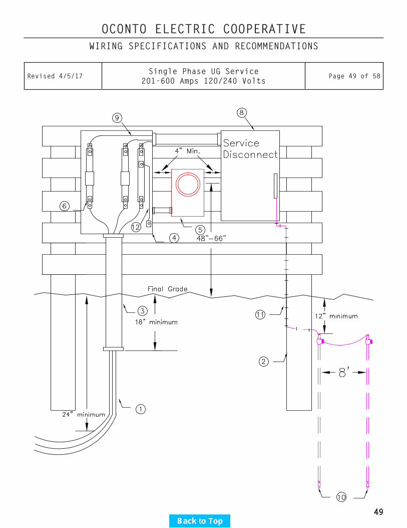
OCONTO ELECTRIC COOPERATIVEWIRING SPECIFICATIONS AND RECOMMENDATIONS
Revised 4/5/17Single Phase UG Service
201-600 Amps 120/240 VoltsPage 49 of 58
49
OCONTO ELECTRIC COOPERATIVEWIRING SPECIFICATIONS AND RECOMMENDATIONS
Revised 4/5/17Three Phase UG Service
200 Amps or Less 120/208 Volts on BuildingPage 50 of 58
1. The Cooperative shall furnish and install the line conductors. Where the Cooperative’s wires will be covered by concrete or blacktop, the member shall provide conduit to extend at least 3 feet beyond the edge of the concrete or blacktop.
2. Member shall furnish and install a 200-amp meter pedestal approved by the Cooperative. (See “Approved Equipment List”) Maintain minimum 4” clear space between meter pedestal and adjacent equipment.
3. Member shall furnish and install load conductors between the meter pedestal and the service disconnecting means. Service entrance conductors shall not extend over 8 feet into a building unless overcurrent protection is provided at the outer end.
4. Member shall furnish and install two 5/8” X 8’ copperclad steel ground rods with approved clamps. Top of rods should be at least 12” below final grade level. (There are other variations of grounding systems as described in the Wisconsin Electrical Code SPS 316 and NEC 250 Section III. These can be connected in addition to the ground rods if desired, but will not be accepted in place of the ground rods.) Ground rods and grounding conductors shall not be installed in front of the meter pedestal or within 2 feet of the underground cable route.
5. The grounding electrode conductor from the ground rods shall not be spliced or terminated in the meter socket or utility portion of the pedestal. The grounding electrode conductor shall be accessible outside of and adjacent to the meter pedestal for connection of telephone, cable TV, or other utility grounding conductors. Ground wire shall be minimum 4 AWG copper wire.
6. Adequate space shall be provided for removal of the meter pedestal cover when concrete or blacktop covers the area in front of the meter pedestal.
7. Member shall furnish and install an extension for the pedestal, if required, to provide a minimum of 18” of pedestal below final grade level.
8. Meter pedestal shall not be installed under any windows.9. An intersystem bonding termination bar shall be provided external to the meter socket for connection of
telephone, cable TV, or other utility grounding conductors.10. Wiring shall be installed in compliance with state electrical code and any local requirements.
50

OCONTO ELECTRIC COOPERATIVEWIRING SPECIFICATIONS AND RECOMMENDATIONS
Revised 4/5/17Three Phase UG Service
200 Amps or Less 120/208 Volts on BuildingPage 51 of 58
51
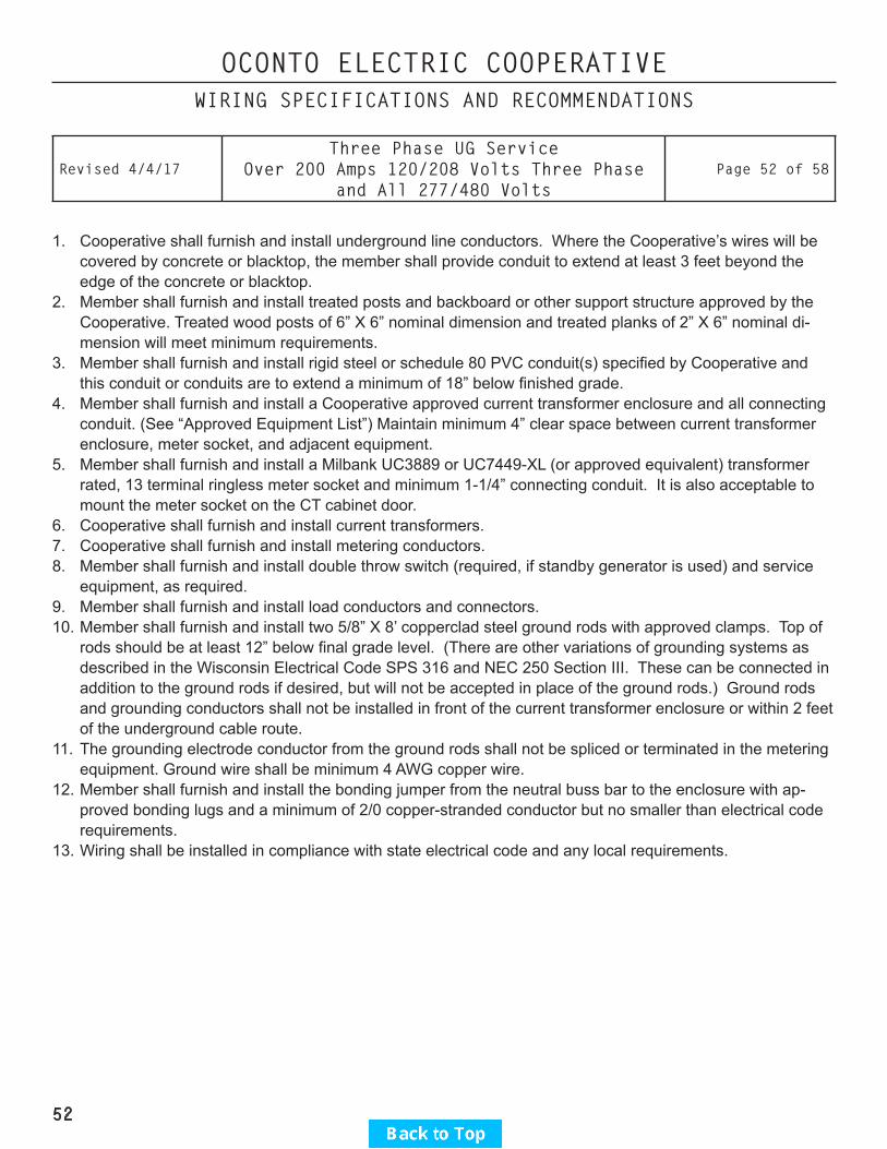
OCONTO ELECTRIC COOPERATIVEWIRING SPECIFICATIONS AND RECOMMENDATIONS
Revised 4/4/17Three Phase UG Service
Over 200 Amps 120/208 Volts Three Phase and All 277/480 Volts
Page 52 of 58
1. Cooperative shall furnish and install underground line conductors. Where the Cooperative’s wires will be covered by concrete or blacktop, the member shall provide conduit to extend at least 3 feet beyond the edge of the concrete or blacktop.
2. Member shall furnish and install treated posts and backboard or other support structure approved by the Cooperative. Treated wood posts of 6” X 6” nominal dimension and treated planks of 2” X 6” nominal di-mension will meet minimum requirements.
3. Member shall furnish and install rigid steel or schedule 80 PVC conduit(s) specified by Cooperative and this conduit or conduits are to extend a minimum of 18” below finished grade.
4. Member shall furnish and install a Cooperative approved current transformer enclosure and all connecting conduit. (See “Approved Equipment List”) Maintain minimum 4” clear space between current transformer enclosure, meter socket, and adjacent equipment.
5. Member shall furnish and install a Milbank UC3889 or UC7449-XL (or approved equivalent) transformer rated, 13 terminal ringless meter socket and minimum 1-1/4” connecting conduit. It is also acceptable to mount the meter socket on the CT cabinet door.
6. Cooperative shall furnish and install current transformers.7. Cooperative shall furnish and install metering conductors.8. Member shall furnish and install double throw switch (required, if standby generator is used) and service
equipment, as required.9. Member shall furnish and install load conductors and connectors.10. Member shall furnish and install two 5/8” X 8’ copperclad steel ground rods with approved clamps. Top of
rods should be at least 12” below final grade level. (There are other variations of grounding systems as described in the Wisconsin Electrical Code SPS 316 and NEC 250 Section III. These can be connected in addition to the ground rods if desired, but will not be accepted in place of the ground rods.) Ground rods and grounding conductors shall not be installed in front of the current transformer enclosure or within 2 feet of the underground cable route.
11. The grounding electrode conductor from the ground rods shall not be spliced or terminated in the metering equipment. Ground wire shall be minimum 4 AWG copper wire.
12. Member shall furnish and install the bonding jumper from the neutral buss bar to the enclosure with ap-proved bonding lugs and a minimum of 2/0 copper-stranded conductor but no smaller than electrical code requirements.
13. Wiring shall be installed in compliance with state electrical code and any local requirements.
52

OCONTO ELECTRIC COOPERATIVEWIRING SPECIFICATIONS AND RECOMMENDATIONS
Revised 4/4/17Three Phase UG Service
Over 200 Amps 120/208 Volts Three Phase and All 277/480 Volts
Page 53 of 58
53

OCONTO ELECTRIC COOPERATIVEWIRING SPECIFICATIONS AND RECOMMENDATIONS
Revised 4/11/17 Meter Ice and Snow Shield Page 54 of 58
Notes:1. The member will be required to provide a snow and ice shield on the pitched side of metal buildings. A
shield is highly recommended for other areas since the member is responsible for damage to the metering and meter sockets.
2. The shield must be capable of protecting the meter and meter sockets.3. Metal shields (min. of 10 gauge) shall be primed and painted with rust-resistant paint.4. Wood or plywood shields shall be supported by braces.
54

OCONTO ELECTRIC COOPERATIVEWIRING SPECIFICATIONS AND RECOMMENDATIONS
Revised 4/11/17 24 Volt Relay & TRF for Dryer Control Page 55 of 58
55

OCONTO ELECTRIC COOPERATIVEWIRING SPECIFICATIONS AND RECOMMENDATIONS
Revised 4/11/17 Current Transformer Wiring Diagram Page 56 of 58
56
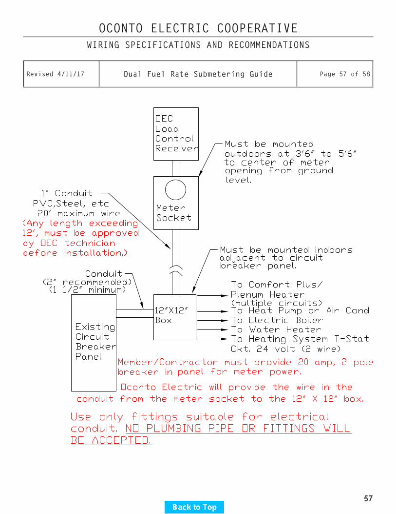
OCONTO ELECTRIC COOPERATIVEWIRING SPECIFICATIONS AND RECOMMENDATIONS
Revised 4/11/17 Dual Fuel Rate Submetering Guide Page 57 of 58
57

OCONTO ELECTRIC COOPERATIVEWIRING SPECIFICATIONS AND RECOMMENDATIONS
Revised 4/11/17 Load Management Receiver Wiring Guide Page 58 of 58
58


