WLD 151 SMAW Certification Practice: Unlimited Thickness Mild Steel This project was supported, in part, by the National Science Foundation Opinions expressed are those of the authors And not necessarily those of the Foundation. 1
Transcript
WLD 151 SMAW Certification Practice:
Unlimited Thickness Mild Steel
This project was supported, in part, by the National Science Foundation Opinions expressed are those of the authors And not necessarily those of the Foundation.
• Understand and practice personal safety by using proper protective gear.• Understand and practice hand tool and power tool safety.• Understand and practice equipment safety for welding and oxy-fuel cutting systems.• Understand and maintain a safe work area.
Recognize and report dangerous electrical and air/gas hose connections. Understand and practice fire prevention.
• Access and explain the importance of the Material Safety Data Sheets (MSDS).
Demonstrate professional work ethics (Habits)
• Track training hours on time card.• Perform projects in accordance to specifications and procedures.• Follow oral and written directions in a positive manner.• Manage time productively.• Respects equipment and others.• Demonstrate skill in problem solving and decision making.
Operate oxyacetylene portable welding units and manifold system
• Demonstrate correct setup and shutdown procedures for the portable welding tanks andmanifold system.
• Perform oxyacetylene welding practice.
Interpret drawing and symbols to accurately layout, prepare and assemble weld joints
• Interpret lines, symbols and verbiage on project drawing.• Layout material per drawing specifications.• Assemble weld project per specification.• Participate in shop cleanup.
Weld groove joints with E7018 welding process to code quality standards in the vertical, and overhead positions
• Develop a working knowledge of the vocabulary used in the welding industry.• Use correct terminology.• Define terms used in the Shielded Metal Arc Welding process.• Equipment identification, setup, shut down, and adjustment of equipment to settings
called for.Welding lead connections, inspection, and proper use Filler rod identification and classification, characteristics, and use
3
• Demonstrate how to adjust travel speed and amount of heat for thickness of material, andweld bead size.
• Demonstrate correct welding techniques with the SMAW welding process.Starting and stoppingOverlapping weldsFollow welding procedure
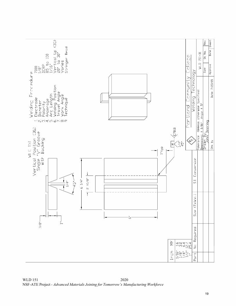
• Demonstrate correct welding techniques in the following joints:Vertical Position:
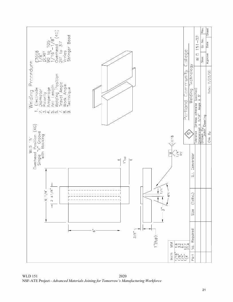
V-groove 3GOverhead Position:
V-Groove 4G• Demonstrate visual examination principles and practices
Know Visual inspection Criteria
Attendance Policy
Students are expected to attend all class meetings for which they are scheduled. Repeated absence will affect the student’s grade. Students are responsible to officially withdraw from a class when they stop attending. If a student has excessive absences and fails to withdraw, a grade of F will be assigned. If you do not attend or stop attending class(es) and fail to personally drop within the refund period, you will be responsible for all tuition and fees.
Full-time students (12 credits) are required to attend class daily for the entire class period.
Part-time students are required to schedule their days and hours of attendance with their instructor. Class dates are established at the beginning of the course. Absence from a scheduled class does not entitle a student to extend their course end date.
STUDENTS MAY ATTEND SCHEDULED HOURS ONLY, THERE ARE NO MAKE UP HOURS. YOUR INSTRUCTOR MUST APPROVE ANY CHANGE IN COURSE SCHEDULE.
Required Texts The Welding Principles and Applications: By Larry Jeffus
Reference List Welding Principles and Applications: by Larry Jeffus Standard Welding Terms and Definitions: ANSI/AWS A3.0-94 AWS D1.1 Structural Steel Welding Code
Timeline: Open-entry, open-exit instructional format allows the students to work their own pace. It is the student’s responsibility for completing all assignments in a timely manner. See your instructor for assistance.
Outcome Assessment Policy: The student will be assessed on his/her ability to demonstrate the development of course outcomes. The methods of assessment may include one or more of the following: oral or written examinations, quizzes, written assignments, visual inspection techniques, welding tests, safe work habits, task performance and work relations.
Contents of this Packet - Importance of Code Qualification- Why Mechanical Properties Testing?- AWS D1.1 Structural Welding Code – Steel- Significance of Bend Testing- Bend Testing of Welds deposited with E7018 and other Low Hydrogen Electrodes- Guided Bend vs. Free Bend Testing- Tensile Testing and Charpy V-Notch Impact Testing
Importance of Code Qualification In all industries, there are applicable codes and standards to assure the quality, reproducibility, and adequacy of welded joints. Depending upon the application, a welded joint may need certain mechanical properties; for example, welds on bridges must pass tests for strength, tensile ductility, bend ductility, and Charpy impact toughness. These codes are based on many years of experience. Changes to codes are ongoing to reflect the dynamic changes that taking place in the industry. There are many welding codes to ensure quality welding. For example, the following is a list of only a few typical industries and governing codes for welding quality.
Pressure Vessels ASME Boiler and Pressure Vessel Code (Vol. IX – Welding Qualifications)
Pipe and Pipelines API Standard 1104; Standard for Welding Pipelines and Related Facilities
Pressure Piping ASME Code for Pressure Piping B31 All Steel Structures AWS D1.1 Structural Welding Code – Steel Buildings AISC Specification for Structural steel Buildings Bridges AASHTO/AWS D1.5; Bridge Welding Code Ships ABS Rules for Building and Classing Steel Vessels Sheet Metal AWS D9.1; Sheet Metal Welding Code Automotive Frames ANSI/AWS D8.8; Specification for Automotive
Frame Weld Quality Aircraft MIL-STD-1595A; Qualification of Aircraft, Missile
and Aerospace Fusion Welders
Why Mechanical Properties Testing? In all codes for welded structures and pipe, various degrees of mechanical testing are performed to assure the quality and integrity of the structure. This includes both procedure qualification and welder qualification. For example, the procedure qualification for steel structures in accordance with the AWS D1.5 Bridge Welding Code–Steel requires that certain welds undergo all-weld-metal tensile testing, transverse-to-weld tensile testing, side bend testing, Charpy v-notch (CVN) impact testing as well as non-destructive testing. Mechanical testing is very important because it ensures that the welding procedure, welder qualification, consumables, and the resulting metallurgy of the weld and heat-affected zone are all acceptable.
AWS D1.1 Structural Steel Welding Code When a structure is going to be built, the owner and contractor agree on the appropriate welding code, which will be needed to govern the acceptability or rejection of structural welds being fabricated. AWS D1.1 Structural Welding Code – Steel is devised to provide welded joints with acceptable strength, ductility, and CVN impact toughness for the intended application, such as a building, general construction, motorized vehicle, etc. Not only are procedure qualification requirements but also welder qualification and certification. The qualification and certification tests for welders are specially designed to determine the welder’s ability to produce sound welds routinely. To achieve these quality standards, the welder qualification and certification provide the means to ensure acceptable welds.
Significance of Bend Testing Of all the tests prescribed by different welding codes, the bend test provides the best and most reliable measure of ductility of the entire weld joint, including the weld metal, heat-affected zone, and unaffected base metal. Welder qualification tests in AWS D1.1 always specify bend testing of welded joints. This is because the bend test is extremely sensitive to all types of metallurgical problems associated with welding. For example, weld joints which have inadequate ductility and fail the bend test may be have been affected by: (a) hydrogen assisted cracking, (b) micro fissuring due internal solidification cracking, (c) excessive slag inclusions, (d) excessive porosity, (e) wrong filler metal, causing embrittlement, (e) wrong welding parameters, causing embrittlement, and (f) other metallurgical factors affecting the ductility of the weld joint.
There are three types of bend tests, (1) side bend, (2) face bend, and (3) root bend. Side bend tests are generally required for welds that are greater than 3/8-inch thick for AWS D1.1 and over ½-inch thick for API-1104. For example, a 2-inch thick butt joint deposited by single-pass electroslag welding could not be tested by face or root bend testing, because the thickness is too great for practical testing. However, a 2-inch thick butt joint can be machined to several 3/8-inch thick side bend specimens and tested easily.
So, face and root bending are used to test the ductility of butt joints that are thinner than 3/8-inch. Whether face bends, root bends, or both face and root bends specimens are required depends upon the code used. In AWS D1.1 Structural Welding Code, both face and root bends are required in most cases. The root bend test determines the adequacy of the root preparation and soundness of the root portion of the weld joint. This is particularly important in open root welding applications. Similarly, the face bend test determines the adequacy of the weld metal deposited on the face of the joint. These specimens must be able to withstand bending strains that are produced when a plunger forces a 3/8-inch thick welded specimen into a guided bend fixture. The plunger, having a specified bend radius, forces the welded bend specimen into a die in order to endure a specified amount of bending (or plastic deformation), that is required by the code for structural applications. From Table 1, the plunger radius and plunger thickness increase with increasing yield strength of the base metal being tested. Bending becomes more difficult with increasing yield strength, because ductility decreases as the strength of the steel increases. Thus, AWS D1.1 permits the bend radius required for welder qualification to increase with increasing yield strength, as shown in Table 1.
Table 1 Specified Bending Parameters for Guided Bend Test for Steel Welds in accordance with AWS D1.1 Structural Welding Code - Steel
Yield Strength Of Base Metal
Plunger Thickness
Plunger Radius Interior Die Opening
Die Radius
50,000psi and less
1 ½” ¾” 2 3/8” 1 3/16”
Over 50,000psi to 90,000psi
2” 1” 2 7/8” 1 7/16”
90,000psi and greater
2 ½” 1 ¼” 3 3/8” 1 11/16”
Bend Testing of Welds deposited with E7018 and other Low Hydrogen electrodes The bend test for steel welds is very sensitive to the presence of diffusible hydrogen in the weld. Typically, these welds will fail in the heat-affected zone of high strength steels. Even if non-destructive testing shows a welded steel to be crack-free, the bend test can activate the hydrogen cracking mechanism in steel weld metal and the heat affected zone. If either the weld metal or heat-affected zone is susceptible to hydrogen cracking, the welded specimen will not pass the guided bend test. The use of E7018 and E7018M electrodes are low hydrogen and should prevent the occurrence of hydrogen assisted cracking in the heat-affected zone of steel welds. In addition to hydrogen assisted cracking, there are many other metallurgical causes for lack of adequate ductility in a welded structure, and the bend test is best suited to separate the “good” welds from the “bad” welds.
Guided Bend vs. Free Bend Testing The most widely used bend test, which is required by most welding codes, is the guided bend test. The benefit of the guided bend test, like that required by the AWS/AASHTO D1.5 Bridge Welding Code and AWS D1.1 Structural Welding Code is that the weld metal, heat affected zone and the unaffected base metal are subject to bending equally. This test requires expensive fixturing and a hydraulic ram to perform the guided bend test.
There is another test called the free bend test. The free bend testing apparatus is less expensive build and is hand-operated. The disadvantage of this test is that all of the zones of the weld joint (weld metal, heat affected zone and unaffected zone) are not bent equally. In free bend testing, the zone(s) having the lowest tensile strength will bend the most, while the zone(s) having the highest strength will bend the least. This effect may hide potential problems in the weld joint. This is why most codes insist on the guided bend test and not the free bend test.
Tensile Testing and Charpy V-Notch Impact Testing For welder qualification and certification in accordance with AWS D1.1, tensile testing and Charpy v- notch (CVN) testing of the test weld are not required. However, in other codes, these tests are also used for welder qualification (in addition to bend testing).
Groove Welding Techniques To make a quality weld when welding a groove joint is important because that weld will most likely be inspected by X-ray or Ultrasonic welding inspection techniques because it is a complete joint penetration (CJP) weld. Hence, here are a few techniques to make a successful weld.
First Adjust the travel speed to control the amount of weld metal deposition. Travel speed controls bead width and penetration. Varying the travel speed so that a consistent width weld will be the outcome. The reason for varying the travel speed is due to the heat build up while welding.
When the arc if first struck a plate is at a lower temperature as compared to when the weld is stopped approximately six inches later. This temperature difference can be approximately 400 degrees Fahrenheit, Hence, it is important to vary the travel speed to maintain a uniform amount of fill because as the plate gets hotter more weld metal will be deposited.
Second Maintaining an even filling of the groove is also essential. When welding, the heat input into the plate will cause a heavier deposition near the end of the weld as compare to the beginning of the weld. This can be corrected by not only adjusting your travel speed but also by adjusting your work angle. With this "side angle" adjustment you can deposit more or less metal on the groove face. This is important because when welding out a groove, it is critical to reference the top shoulder on the groove face to keep an even fill for the length of the weld. This will technique will provide for a smoother more even foundation for the cover passes (finish beads).
Review the effects of: • Travel speed• Electrode angle (both work and travel)• Bead placement and Planning• Inter-pass cleaning• Heat input control.
This section will familiarize the student with inspection criteria that will be applied to the evaluation of their projects. PCC Welding Department utilizes the visual inspection requirements set forth in AWS D1.1. The following criteria are gathered from this source.
Undercut Is a condition where the base metal has been melted away during the welding operation and there is insufficient filler metal deposited to adequately fill the resulting depression. These grooves vary in depth and length. Undercut can be present at a weld-to-weld junction or a weld to base metal junction (toe of weld). Undercut causes a stress concentration point (stress riser) that is a potential starting point for weld cracking.
Causes: Improper welding technique Arc length too long Oscillation too abrupt, not spending enough time on the sides of the puddle. Amperage too high Base material too hot Travel speed too fast
Maximum undercut allowed is 1/32” in depth for welder qualification requirements.
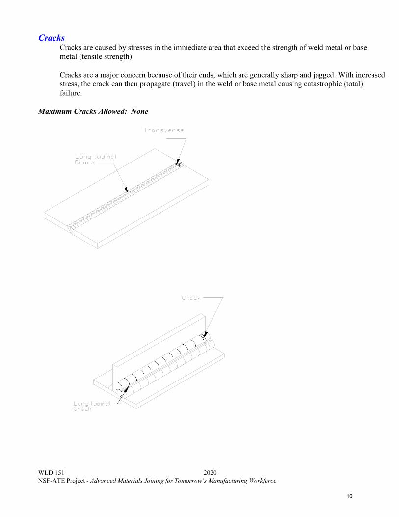
Cracks Cracks are caused by stresses in the immediate area that exceed the strength of weld metal or base metal (tensile strength).
Cracks are a major concern because of their ends, which are generally sharp and jagged. With increased stress, the crack can then propagate (travel) in the weld or base metal causing catastrophic (total) failure.
Porosity Cavity type discontinuities caused by gas trapped during weld solidification. Due to its spherical shape, porosity is considered the least detrimental discontinuity.
Causes: Loss of shielding gas Base metal contamination (oils, grease, water) Too long of an arc.
Visual porosity is unacceptable for welder qualification requirements.
Overlap (Also known as: Cold Lap, Roll Over or Cold Roll) Is the protrusion of weld metal beyond the weld toe or root. Due to its linearity and relatively sharp end condition, over lap represents a significant weld discontinuity.
Slag Inclusions Slag is a nonmetallic by product of the welding process. If slag is not cleaned out thoroughly prior to depositing the next pass it can be trapped. Or, if the previous weld(s) have poor weld profile slag can become trapped in the crevices when welded over.
Slag inclusions are most often caused by improper cleaning, improper electrode manipulation and or poor bead placement.
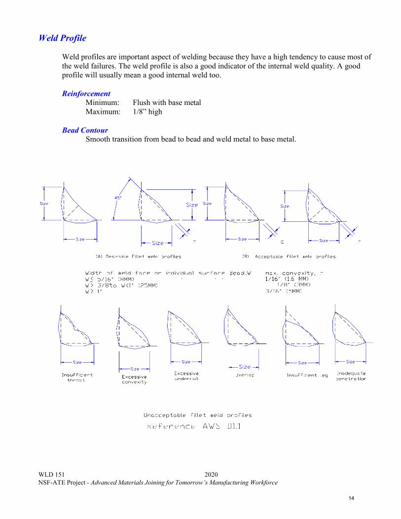
Weld profiles are important aspect of welding because they have a high tendency to cause most of the weld failures. The weld profile is also a good indicator of the internal weld quality. A good profile will usually mean a good internal weld too.
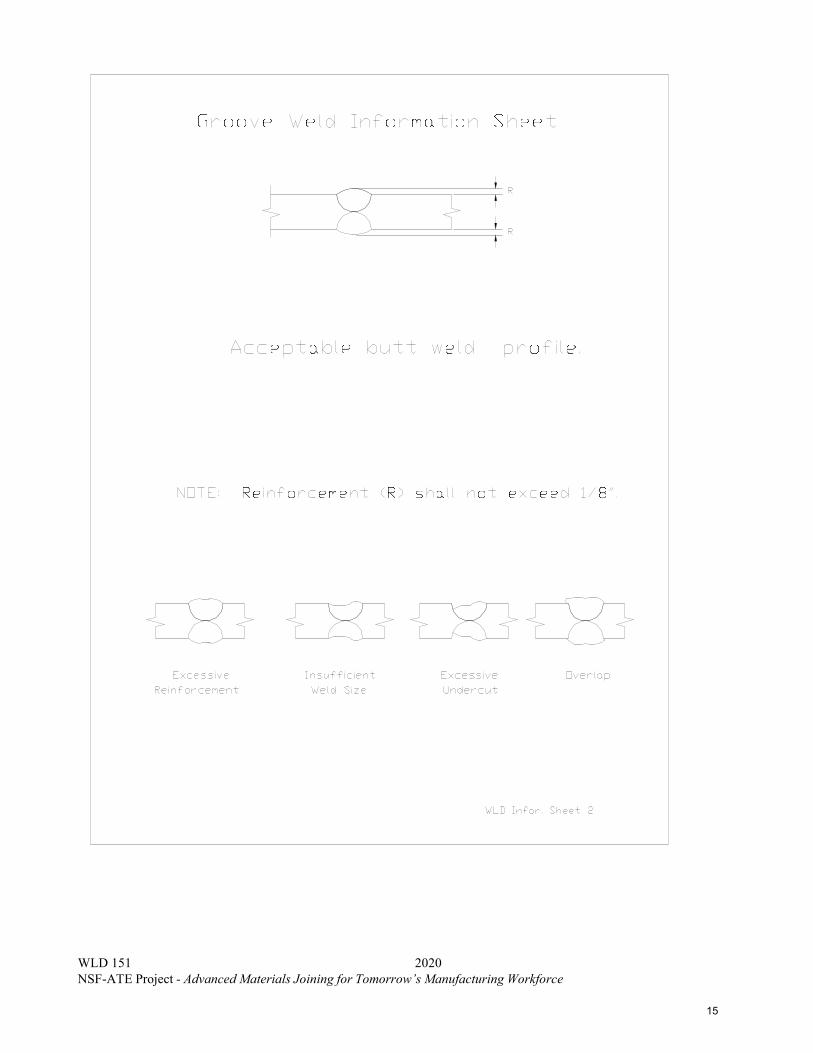
Reinforcement Minimum: Flush with base metal Maximum: 1/8” high
Bead Contour Smooth transition from bead to bead and weld metal to base metal.
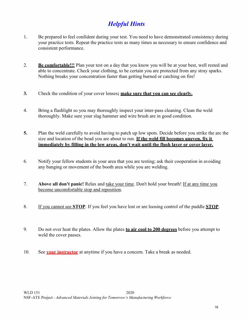
1. Be prepared to feel confident during your test. You need to have demonstrated consistency duringyour practice tests. Repeat the practice tests as many times as necessary to ensure confidence andconsistent performance.
2. Be comfortable!!! Plan your test on a day that you know you will be at your best, well rested andable to concentrate. Check your clothing, to be certain you are protected from any stray sparks.Nothing breaks your concentration faster than getting burned or catching on fire!
3. Check the condition of your cover lenses; make sure that you can see clearly.
4. Bring a flashlight so you may thoroughly inspect your inter-pass cleaning. Clean the weldthoroughly. Make sure your slag hammer and wire brush are in good condition.
5. Plan the weld carefully to avoid having to patch up low spots. Decide before you strike the arc thesize and location of the bead you are about to run. If the weld fill becomes uneven, fix itimmediately by filling in the low areas, don't wait until the flush layer or cover layer.
6. Notify your fellow students in your area that you are testing; ask their cooperation in avoidingany banging or movement of the booth area while you are welding.
7. Above all don't panic! Relax and take your time. Don't hold your breath! If at any time youbecome uncomfortable stop and reposition.
8. If you cannot see STOP. If you feel you have lost or are loosing control of the puddle STOP.
9. Do not over heat the plates. Allow the plates to air cool to 200 degrees before you attempt toweld the cover passes.
10. See your instructor at anytime if you have a concern. Take a break as needed.
The student should complete the following tasks prior to welding. 1. Thoroughly read each drawing.2. Make a cutting list for each project. Cut at least two project assemblies of metal at a time.
This will save a great amount of time.3. Assemble the welding projects per drawing specifications.4. Review the Welding Procedure portion of the prints to review welding parameter
information.5. See the instructor for the evaluation.
Factors for grading welding projects are based on the following criteria:
Metal Preparation Project Layout Post Weld Clean-up Oxyacetylene Cut quality Accurate (+/- 1/16”) Remove Slag/Spatter Grind all cut surfaces clean Limit waste Remove sharp edges
Example of a High Quality Weld
Weld Quality per AWS D1.1 VT Criteria Cover Pass Reinforcement (groove welds) Flush to 1/8” Fillet Weld Size See specification on drawing Undercut 1/32” deep Weld Contour Smooth Transition Penetration N/A Cracks None Allowed Arc Strikes None Allowed Fusion Complete Fusion Required Porosity None Allowed Overlap None Allowed
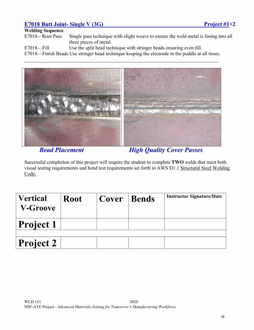
E7018 Butt Joint- Single V (3G) Project #1+2 Welding Sequence E7018-- Root Pass Single pass technique with slight weave to ensure the weld metal is fusing into all
three pieces of metal. E7018—Fill Use the split bead technique with stringer beads ensuring even fill. E7018—Finish Beads Use stringer bead technique keeping the electrode in the puddle at all times.
Bead Placement High Quality Cover Passes
Successful completion of this project will require the student to complete TWO welds that meet both visual testing requirements and bend test requirements set forth in AWS D1.1 Structural Steel Welding Code.
E7018 Butt Joint- Single V (4G) Project #3+4Welding Sequence E7018-- Root Pass Single pass technique with slight weave to ensure the weld metal is fusing
into all three pieces. E7018—Fill Use the split bead technique with stringer beads ensuring even fill. E7018—Finish Beads Use stringer bead technique keeping the electrode in the puddle at all
times.
Bead Placement High Quality Cover Passes
Successful completion of this project will require the student to complete TWO welds that meet both visual testing requirements and bend test requirements set forth in AWS D1.1 Structural Steel Welding Code.
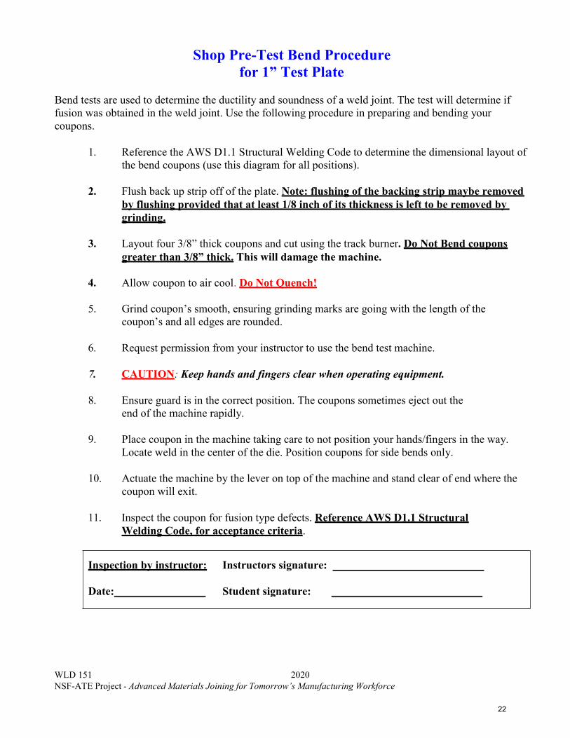
Bend tests are used to determine the ductility and soundness of a weld joint. The test will determine if fusion was obtained in the weld joint. Use the following procedure in preparing and bending your coupons.
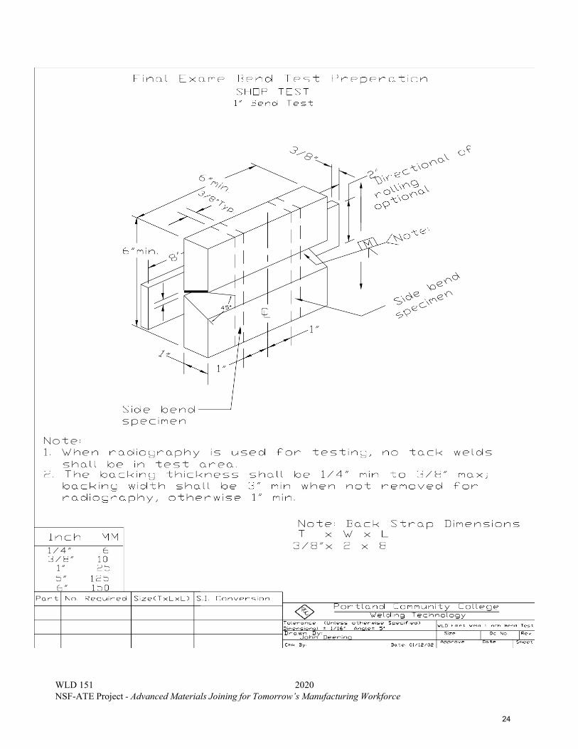
1. Reference the AWS D1.1 Structural Welding Code to determine the dimensional layout ofthe bend coupons (use this diagram for all positions).
2. Flush back up strip off of the plate. Note: flushing of the backing strip maybe removedby flushing provided that at least 1/8 inch of its thickness is left to be removed bygrinding.
3. Layout four 3/8” thick coupons and cut using the track burner. Do Not Bend couponsgreater than 3/8” thick. This will damage the machine.
4. Allow coupon to air cool. Do Not Quench!
5. Grind coupon’s smooth, ensuring grinding marks are going with the length of thecoupon’s and all edges are rounded.
6. Request permission from your instructor to use the bend test machine.
7. CAUTION: Keep hands and fingers clear when operating equipment.
8. Ensure guard is in the correct position. The coupons sometimes eject out theend of the machine rapidly.
9. Place coupon in the machine taking care to not position your hands/fingers in the way.Locate weld in the center of the die. Position coupons for side bends only.
10. Actuate the machine by the lever on top of the machine and stand clear of end where thecoupon will exit.
11. Inspect the coupon for fusion type defects. Reference AWS D1.1 StructuralWelding Code, for acceptance criteria.
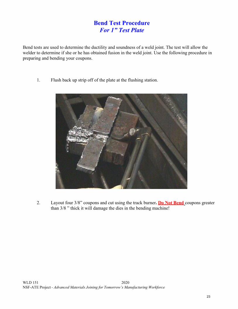
Bend tests are used to determine the ductility and soundness of a weld joint. The test will allow the welder to determine if she or he has obtained fusion in the weld joint. Use the following procedure in preparing and bending your coupons.
1. Flush back up strip off of the plate at the flushing station.
2. Layout four 3/8” coupons and cut using the track burner. Do Not Bend coupons greaterthan 3/8 ” thick it will damage the dies in the bending machine!
A. The test must be complete. The full length (6”) of the test plate will be visuallyinspected. Use your run off tabs throughout the test to insure quality results at the startand finish at both ends of the plates. All craters shall be filled to the full cross sectionof the weld.
B. Reinforcement layer (cover pass) height shall be Flush to 1/8” (3 mm) above theplate.
C. A reinforcement layer higher that 1/8” (3 mm) will not be accepted.
D. Weld width cannot exceed ¼” wider than original groove opening.
E. Weld shall merge smoothly with the base metal.
F. Weld must be free of porosity, slag inclusions, and/or cold lap.
G. Undercut shall not exceed 1/32 in. (1 mm).
H. Arc strikes outside of the weld area are NOT acceptable.
Part One The final exam is a closed book test. Consult your instructor to determine items that you may need to review. Once you determine that you are ready for final written exam see your instructor. Complete the exam and write all answers on the answer sheet. Once completed, return the exam to your instructor.
Part Two Using the Welding procedure in the packet, complete the practical test.
Directions Reference Chapter 19 and the index in your Welding Principles and Applications text and utilize that information to complete the questions on this work sheet. Answer the questions using complete sentences, and do not hesitate to reference other sections in the text to find an answer.
1. What are codes and standards?
2. Why is it important to select the correct welding code or standard?
3. What is the difference between welding codes or standards and welding specifications?
4. What does the following abbreviations stand for:
Directions: Read chapter 20 in the Welding Principles and Welding Applications text and utilize that information to complete the questions on this work sheet. Answer the questions using complete sentences, and do not hesitate to reference other sections in the text to find an answer.
1. Why are all welds not inspected to the same level or standard?
2. Why is the strength of all production parts not known if a sample number of parts aremechanically tested?
.
3. Why is it possible to do more than on nondestructive test on a weldment?
20. How can stress be reduced through a plate’s thickness to reduce lamellar tearing?
21. What would be the tensile strength in pounds per square inch of a specimenmeasuring 0.375 in. thick and 1.0 in. wide if it failed at 27,000 pounds?
22. What would be the elongation for a specimen for which the original gauge length was 2 in. andfinal gauge length was 2.5 in.?
23. How are the results of a stress test reported?
24. How are the specimens bent for a guided bend root, face, and side bend test?
25. What part of a fillet weld break test is examined?
26. Which nondestructive test is the most commonly used test?
45
Welder Certification
Name: Date:
Directions Reference chapter 21 and the index in the Welding Principles and Applications text and utilize that information to complete the questions on this work sheet. List the section where your answers were obtained in the code. Answer the questions using complete sentences, and do not hesitate to reference other sections in the code to find an answer.
1. How does applying for a welding job differ from most other types of jobs?
2. What is the major difference between a qualified welder and a certified welder?
3. What process can a welder be certified for?
4. List the variables that, if changed, would require that a new certification test be given.
5. What is required to become an AWS Certified Welder?
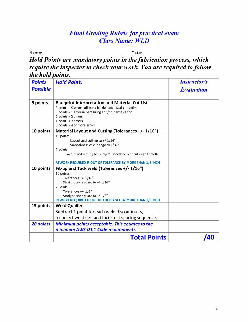
Final Grading Rubric for practical exam Class Name: WLD
Name: Date: Hold Points are mandatory points in the fabrication process, which require the inspector to check your work. You are required to follow the hold points. Points Possible
Hold Points Instructor’s Evaluation
5 points Blueprint Interpretation and Material Cut List 5 points = 0 errors, all parts labeled and sized correctly 3 points = 1 error in part sizing and/or identification 2 points = 2 errors 1 point = 3 errors 0 points = 4 or more errors
10 points Material Layout and Cutting (Tolerances +/- 1/16”) 10 points
Layout and cutting to +/-1/16” Smoothness of cut edge to 1/32”
7 points Layout and cutting to +/- 1/8” Smoothness of cut edge to 1/16
REWORK REQUIRED IF OUT OF TOLERANCE BY MORE THAN 1/8 INCH