73
2017-18

Workshop Practice 15WSL16/26
C.I.T, GUBBI. 1 Dept. of Mech. Engg.
2017-18

Workshop Practice 15WSL16/26
C.I.T, GUBBI. 2 Dept. of Mech. Engg.

Workshop Practice 15WSL16/26
C.I.T, GUBBI. 3 Dept. of Mech. Engg.
N a m e :_ __ __ __ __ __ __ __ __ __ __ ___ __ _
C las s/ S ec tio n : _ __ __ __ ___ __ __ __ __ __ _
R o ll N o . : __ __ __ __ __ ___ __ __ __ __ __ __ _
U S N : _ __ __ __ __ __ __ __ __ __ ___ __ __
has satisfactorily completed the course of
prescribed by the Visvesvaraya Technological University, Belagavi
in the Year __________
"WORKSHOP PRACTICE"
Signature of staff in-charge Signature of Head of the Department
Class Marks
20
This is to Certify that

Workshop Practice 15WSL16/26
C.I.T, GUBBI. 4 Dept. of Mech. Engg.

Workshop Practice 15WSL16/26
C.I.T, GUBBI. 5 Dept. of Mech. Engg.

Workshop Practice 15WSL16/26
C.I.T, GUBBI. 6 Dept. of Mech. Engg.
+ SAFETY IN SHOP +
Observe the following safety to avoid injury to your self and co-workers
1. Be well dressed i.e., avoid loose garments, roll up sleeves, put on suitable footwear
and remove watch and ring.
2. Keep the work place neat and clean i.e., place the tools at proper position. The
scraps and chips should be dropped in waste bins.
3. Concentrate on your job and avoid talking with co-workers.
4. The shops are no place to play. Running and pushing in the shop may cause
accidents.
5. Understand the use of tools and machines before handling.
6. Never use dull tools. The use may damage the tools completely or may lead to
injury.
7. In case you are in doubt contact the instructor.
8. Always chuck the fitting of the handle in the hammerhead.
9. Be familiar with the locations of First Aid Box and Fire Extinguisher in the shop.
In case of emergency one should reach them quickly.
10. Laziness and carelessness are your deadly enemies. Always be active and careful
in the shop.
PREVENTION IS BETTER THAN CURE

Workshop Practice 15WSL16/26
C.I.T, GUBBI. 7 Dept. of Mech. Engg.
SAFETY FIRST – WORK NEXT

Workshop Practice 15WSL16/26
C.I.T, GUBBI. 8 Dept. of Mech. Engg.
SYLLABUS
WORKSHOP PRACTICE LAB
Sub code : 15WSL16 / 15WSL26 IA Marks : 20
Labs / Tutorial Hours/Week 3 (1 hr Tut +2 hrs lab) Exam Hours: 03
Total Hours : 42 Exam Marks: 80
Course Objectives:
To impart knowledge and skill to use tools, machines, equipment, and measuring
instruments.
Educate students of Safe handling of machines and tools.
Students belonging to all branches of Engineering are trained in understanding fundamental
metal removing process like fitting and joining processes like welding and soldering.
1. Demonstration on use of Hand Tools: V-block, Marking Gauge, Files, Hack Saw, Drills,
Taps.Minimum 3 models involving Dove tail joint,Triangular joint and Semicircular joint.
2. Welding: Study of electric arc welding tools & equipments, Models: Butt Joint, Lap Joint,
T- Joint & L – Joint.
3. Sheet metal & soldering work:
Development & soldering of the models: Frustum of Cone, Prisms (Hexagon & pentagon),
Truncated Square Pyramid, Funnel.
Course outcomes: At the end of the course, the student will be able to:
1. Demonstrate and produce different types of fitting models.
2. Gain knowledge of development of sheet metal models with an understanding of their
applications.
3. Perform soldering and welding of different sheet metal & welded joints.
4. Understand the Basics of Workshop practices.
Reference Books:
1. Elements of workshop Technology:
Vol 1: Manufacturing Processes,
S K Hajra Choudhury A,
K Hajra Choudhury, 15th
Edition required 2013,
Media promoters & publishers Pvt Ltd, Mumbai.
Note: No mini drafters and drawing boards required. Drawings (Developments) can be
done on sketch sheets using scale, pencil and geometrical instruments.

Workshop Practice 15WSL16/26
C.I.T, GUBBI. 9 Dept. of Mech. Engg.
QMP 8.1
R/F Rev.1
Channabasaveshwara Institute of Technology
(Accredited by NBA & ISO 9001:2008 Certified Institution)
NH 206 (B.H. Road), Gubbi, Tumkur – 572 216. Karnataka.
DEPARTMENT OF MECHANICAL ENGINEERING
LECTURE PLAN
Faculty Name: Section:
Semester: Sub code: 15WSL16/26
Subject: WORKSHOP PRACTICE
Plan
No Date Topics Signature
LP1
Professional activities of an engineer.
What is workshop & their benefits, safety in workshop.
Syllabus:
Engineering drawing & their application to perform the job
2D, 3D & free hand sketch.
Information required to perform the job.
To draw the sketches of the Triangular Joint, Hexagonal & Pentagonal Prism.
Demonstration to make use of vernier height gauge
LP2
What is fitting & their application.
What is sheet metal working & their application?
Step by step working procedure to perform the fitting and sheet metal job.
Demonstration of preparing Triangular joint.
Demonstration of preparing Hexagonal & Pentagonal Prism
Continue to practice of the above said models.
LP3
What is development & their methods, template in sheet metal work.
Fitting operations. Continue to practice of triangular joint & complete it Continue to practice of making Hexagonal & Pentagonal prism &
Complete it.
LP4
Sheet metal operations & tools required to perform the sheet metal products.
Interchanging of fitting & sheet metal jobs.
Conducting viva voce.

Workshop Practice 15WSL16/26
C.I.T, GUBBI. 10 Dept. of Mech. Engg.
LP5
Instruction on welding & to show the Arc welding equipment’s.
Sheet metal: Instruction to perform Rectangular Tray, Dust Pan & Taper Tray.
Fitting: Instruction on Dovetail Joint, continue practice the above jobs.
Conducting viva voce.
LP6
Demonstration of the Arc welding & procedure to perform Arc welding joints.
To perform Dovetail joint.
To perform Tray, Dust pan & Taper Tray.
Conducting Viva Voce.
LP7
Instruction for preparing development of a funnel.
To Prepare Butt joint in welding.
To complete the tray, Dust pan & Taper Tray in sheet metal.
To Complete the Dovetail Joint.
Conducting Viva-Voce.
LP8
Study of engineering materials.
To prepare development of Funnel & perform the job.
Instruction of semicircular joint & continue to perform job.
To prepare LAP joint in Arc welding
Conducting Viva-voce.
LP9
Study of all fitting tools & Instruments.
Interchange of Semicircular joint & Funnel.
T Joint in Arc welding.
Conducting viva voce.
LP10
Instruction on fundamentals manufacturing process used in Engineering.
Comparison of Welding, Brazing & Soldering.
Instruction for preparing Truncated Square Pyramid.
To prepare corner Joint in Arc welding.
LP11 Workshop Internals
LP12 Workshop Internals
LP13
DEMONSTRATION OF PREPARING TAPPING & DIEING.
To prepare Truncated Square Pyramid.
To complete Semicircular Joint.
To conducting Viva-Voce.
LP14
Demonstration of power operated machine tools in Mechanical Engineering.
Complete all remaining work & submit for final evaluation.
To conducting viva voce
Staff in charge HOD

Workshop Practice 15WSL16/26
C.I.T, GUBBI. 11 Dept. of Mech. Engg.
Engineering:-
Engineering is a professional art of applying science and technology to optimize the
conversion of natural resources to the benefit of mankind. (Natural resources available
in the universe are Iron ore, Air, Sun, Water, Space, Human etc.)
Human resource is a supreme strength to develop Engineering to contribute the
welfare and progress of the society or to this nation.
Engineer:-
Engineer is a person having creative thoughts and ideas to develop technology for the
noble cause of the society or to nation.
All objects begins an idea, Conceived and visualized by the Engineer. He makes an
internal representation of the object in his mind and communicates it to others through
media of expression.
Professional activities of an engineer:
1. Planning: (Proposal of doing something)
It means a set of preparation is to do in order to achieve something or any kind of
task/work. (Preparation means programmes, drawings, Materials requirement and
their sources, time schedule, cost estimate, scheme and design and method of
preparation etc.)
It is a management function of defining goal of an individual / organizations.
It determines the task/work and resources necessary to achieve set goals.
It helps to save materials, labor, time, money efforts and process etc. so that any kind
of work/task can be performed successfully without having any difficulty with full
confidence.
2. Visualization (related to vision / creating picture in mind)
It is a behavioral technique of improving performance of his individual.
It encourage for creating mental picture for successful execution of any work.
3. Hard work and practice (doing something repeatedly)
There is no substitute for hard work. A spiritual person says that “Work is Worship”,
“Practice makes the man perfect”. Practice makes a person to acquire skill to use their
knowledge for gaining self assurance and confidence to handle any kind of work without any
difficulty.
4. Punctuality (being in time):
Punctuality is a moral goodness, which is to be practiced very well punctuality is nothing but
courtesy to others. By being punctual you respect the value of time of others. This is more
than anything else. It helps you to plan your activities and schedule with precision and
efficiency.
5. Work place Environment:
Workplace environment is to be maintained neat and clean, and spread happiness, cheerful,
love & affection around your work place, at home and also to the community.

Workshop Practice 15WSL16/26
C.I.T, GUBBI. 12 Dept. of Mech. Engg.
6. Efficiency: It is the ability to do what ever we expected of us as promptly accurately and
economically as possible.
These activities are to be performed by an engineer to maintain quality and integrity for
successful execution of any task & to face the challenge of globalization.
Workshop:-
It is a place of work for preparing variety of jobs/products by using different kinds of
Instruments, hand tools and Machines.
In order to prepare the products in W/s, the w/s is divided in to many branches according to
nature of work.
Ex: 1.Fitting shop
2. Welding shop
3. Sheet metal shop
4. M/c Shop
5. Foundry & Forging shop etc
What are the information required to prepare the product?
It is a common experience that when we want to prepare any product, the following
information are required. 1. Actual Shape
2. Accurate Size
3. Manufacturing Method
Before taking up the construction of a product, the person who prepares it must have a clear
picture of the shape and size of the object in his mind and to know the method of
manufacturing process for successful execution of the work.
Engineering Drawing:-
A graphic form of representation of an object which contains all the necessary information
like actual shape, accurate size, manufacturing methods etc. required for construction of an
object is called Engineering Drawing. It is prepared on certain basic principles, symbolic
representation, standard conventions, notations etc.
Engineering drawing is said to be the language of an engineer and it can be considered as a
powerful tool to convey his ideas.
In Engineering, it is a practice to record ideas in the form drawing. Since engineering
drawing is a graphical medium of expression of all technical details without the barrier of
word language. It is also called the universal language of an engineer.
1. Orthographic projection or view. : 2D
2. Isometric projection or view. 3D
Elements of Dimensioning
1. Aligned system.
2. Uni-directional systems
Line Conventions:
1. All visible out lines, edges are drawn in bold, i.e. thick continuous lines.
2. Dimension lines, projection line, leader lines are drawn thin continuous.
3. Arrowhead and dimension figure are shown thick.
35
35

Workshop Practice 15WSL16/26
C.I.T, GUBBI. 13 Dept. of Mech. Engg.
Free hand Sketching:
1. Drawing of 2D/3D sketches is drawn using only pencil and eraser is called Free Hand
Sketch.
2. Designers, teachers/ instructors and artists use this for immediate graphical
communications.
3. To start with Graph/grid sheets help in practice well
4. The parallel horizontal lines are to be drawn from left to right by right handed people
and right to left from left handed people.
5. Vertical lines are to be drawn from top to bottom.
6. Inclined lines are to be drawn from lower left to upper right.
7. Small arcs, circles and ellipses may be drawn in one motion on a trial basis.
8. Big circles and ellipses may drawn by box method.
Prime use of free hand sketches:
1. To serve teaching aid during discussion in class rooms.
2. To prepare tabular column.
3. To sketch circuit diagram of electrical engineering problem.
4. To prepare the layouts of laboratory, Buildings & Production shops etc.
5. To convey information regarding repair of machine on spot.
6. To help the designer is developing new ideas.
7. To covey the idea’s of the designer to the draughtsman, management etc.
8. To serve as a basis for discussion between engineers and workmen in the shop floor.
Orthographic View or Projection or 2 D:-
In the orthographic projection, two or more number of principle views are drawn to
show the shape and sizes of an object.
Front View: The object is viewed or seen from the front, the shape & size formed in
Vertical Plane is called the Front View or Elevation.
Top View: The object is viewed or seen from the Top, the shape & size is formed
in Horizontal Plane is called Top View or PLAN.
Side View: The object is viewed or seen from the left or right, the shape & size is
formed in Profile Plane is called Left or Right View.
NOTE: To obtains the view of an object to same size. The visual rays should run on parallel
to each other and perpendicular to plane of projections. All Orthographic views are
two dimensional.
ISOMETRIC PROJECTION (OR) Pictorial drawing:-
Isometric projection is a 3D (pictorial) view.
It enables the observer not only see the three dimensions of an object in a single view
but also measure them directly.
This is used to convey information to persons, who cannot visualize an object from
2D views and also to show complicated structures such as Air Craft, Rocket cell,
Service manual layout of pipelines, assembly and disassembly of parts required in
maintenance.

Workshop Practice 15WSL16/26
C.I.T, GUBBI. 14 Dept. of Mech. Engg.
ISOMETRIC CONSTRUCTION:-
When once the Orthographic projection are drawn using isometric scale, then simply
transferred the distances from the orthographic views to get the isometric projection.
Differences between isometric projection & isometric view or drawing
What are the fundamental manufacturing processes used in shaping the metal products?
There are four fundamental manufacturing processes used in Engineering.
1. Casting process: In this process, the shape is formed by pouring molten metal into a
mould (Hallow Cavity by refractory material)
2. Forging processes: In this process, the shape is formed by mechanical pressing or
forging in both hot and cold condition.
3. Machining process: In this process, the shape is formed by various machining
operations by machines (Drilling machines, Lathe, Grinding machine, Milling
Machine etc.)
4. Fabrication Process: It is the name given to the process of making the product from
pieces by joining.
The fabrication process itself can be further subdivided into :
1. Fitting: Mechanical joining by the use of interlocking joints, bolts & nuts, screws,
rivets, and fasteners.
2. Welding : Where metallurgical union is achieved between the parts to be joined by
application of heat and pressure.
3. Brazing and Soldering: Where metallurgical union is effected by inserting a metal
between the parts to be jointed. The metal having lower melting point than the parts.
4. Adhesive bonding: Where the metal parts are joined by use of resin or some other
adhesives. Eg. Grinding wheel, cutoff wheels.

Workshop Practice 15WSL16/26
C.I.T, GUBBI. 15 Dept. of Mech. Engg.
FITTING
It is a process of joining two or more metal pieces of metals by performing various operations
like measuring, marking, punching, drilling, hack sawing, chipping, filing, tapping and
dyeing to make a perfect fit is called Fitting.
Process to make the Joint Study of Drawing.
Separation of Two Pieces.
Note Down Marking Dimensions.
Filing of Shorter Edges and Rubbing.
Letters Punch A & B Pieces.
Marking.
Performing Fitting Operations.
Joining with Perfect Fit.
Practical Applications: Joining of Automobile and Machine parts.
Preparing a Key for Lock.
Some common fitting operations:
1. Measuring 8. Hack sawing
2. Marking 9. Chipping
3. Punching 10.Filing
4. Drilling 11.Scraping
5. Reaming 12. Tapping
6. Boring 13. Dieing
7. Counter Boring 14. Grinding
1 Measuring : It is a process of finding the dimensions of the work piece by
using steel scale, calipers, micrometer, gauge etc.
2 Marking : Making a series of definite lines on the job. These lines act as
guidelines to the fitter who works on the job.
3 Punching : It is the operation of making series of dent or punch marks on the
line of marking using center punch and ball peen hammer.
4 Drilling : It is the operation of producing holes in the solid materials using
Drilling Machine with suitable drill bit.
5 Reaming : It is the operation of smoothening the inner surface of the drilled
hole with a reamer.
6 Boring : Boring is the operation of enlarging the size of Previously drilled
hole.
7 Counter Boring : It is the operation of increasing the size of the hole at one end
through a small depth using counter bore tool.
8 Cutting or
Hack Sawing
: It is the operation of cutting flat, round rods, pipes etc. using
hacksaw frame with suitable blade.
9 Chipping : It is the operation or removing thick layer of metal using cold
chisel.

Workshop Practice 15WSL16/26
C.I.T, GUBBI. 16 Dept. of Mech. Engg.
10 Filing : It is the operation of removing thin layer of metal using different
types of files.
11 Scraping : It is the operation of producing a precision surface or smooth a
accurate surface. This is done with tools called scrapers, which
have very hard with no rake.
12 Tapping : It is the operation of cutting internal threads with a thread cutting
tool called taps. Drill size for taping= size of the tap- pitch of the
thread.
13 Dieing : It is the operation of cutting external threads using die set.
14 Grinding : Grinding is the process of removing metal using grinding wheel.
Grinding is a finishing operation used for accuracy and
smoothness. The accuracy in grinding is in the order of 25
microns.
What is the need for maintenance of machine and equipment? It is necessary to properly maintain machine and equipment to obtain long life of
machine. Maintenance can be done by cleaning of machines, oiling of various parts of
machines and by regular maintenance done daily, weekly, monthly or yearly. The life of
machine will increase it will avoid the sudden breakdown and machine will not stop and by
this production can be increased.
What are the advantages of preventive maintenance? Describe. Preventive maintenance means planning and scheduling the maintenance in advance.
1. To avoid sudden breakdown of machine
2. Damage of costly parts is avoided
3. Shut down of production is avoided
4. Longer life of equipment is ensured
5. Possibility of serious accidents is minimized
6. Preventive maintenance is less cost than breakdown maintenance
7. Preventive maintenance can be planned in advance.
What are the benefits of workshop practice?
1. This practice help in proper “Planning” and time scheduling of work while preparing an
object as it avoids unnecessary waste of time, material money and efforts and process.
2. It help in “Visualizing “the actual shape and size of the object.
3. The ability to read and draw the orthographic (2D) and Isometric projections (3D) as it
improve s the communication skill through “Graphic language”. (media of expression)
4. To know the name specification use and other details of “hand tools’, “instruments” and
“machines”.
5. It helps in learning a systematic working procedure ‘Work style and culture” as it
improves quality of work and for improving performance of body language.
6. The hard work and practice make the person to become more active, efficient, smart and
talented.
7. It helps to follow the work safety rules regulations to avoid injury and accident himself.
8. It is providing information in engineering work as it improves personality development
and self discipline.

Workshop Practice 15WSL16/26
C.I.T, GUBBI. 17 Dept. of Mech. Engg.
What are Engineering Materials?
Materials which are used in the Engineering practice/purpose are called engineering
materials. These have Physical, Mechanical and chemical Properties.
Engineering Materials
Metals Non Metals
Ferrous Metals Non-Ferrous Metal
Iron Steel
i. Pig iron
ii. Cast Iron
iii. Wrough Iron Plain Carbon Steel Alloy Steel
Dead Mild Steel Medium High Carbon
Mild Steel Carbon Steel Steel
METALS:
A metal is a solid (Expect Mercury) having weight. It is opaque and a good conductor of heat
and electricity.
NON- METALS:
These available in the form of liquids, gases or solids such as Wood, Stone, Rubber, Plastic,
Ceramic, Concrete, Asbestos etc.
FERROUS METALS:
Iron containing metals such as pig iron, wrought Iron, Cast Iron, Steel, Carbon Steel, Nickel
Steel etc, are called ferrous metals. These can be attracted by magnets and are susceptible to
rusting.
NON- FERROUS METALS:
Metals like Gold, Silver, Copper, Aluminium, Tin, Platinum, Zinc, neither rust nor can be
attracted by magnets.
IRON:
Metal like Pig Iron, Cast Iron, Wrought Iron containing small percentage of carbon with
Graphite, Silicon, Manganese, Sulphur & Rest Iron.
STEEL:
It is an alloy of iron and carbon in addition there are minute percentage of Silicon,
Phosphorus, Sulphur and Manganese.
ALLOY STEEL:
In addition to iron and Carbon, alloying elements such as chromium Nickel, Tungsten cobalt,
Vanadium are mixed. Ex. Stainless Steel (SS), High Speed Steel (H.S.S)
(in addition to Carbon & Iron, alloying elements such as Chromium, Nickel,
Tungsten, Cobalt, Vanadium are mixed. Ex. Stainless steel, High
Speed Steel (HSS))

Workshop Practice 15WSL16/26
C.I.T, GUBBI. 18 Dept. of Mech. Engg.
FERROUS METALS, COMPOSITION AND THEIR USES
Sl.
No.
METALS MAIN COMPOSITION
(General)
USES
1 Pig Iron
(White pig Iron)
(A Product from Blast
Furnace)
0.3 - 2% C with graphite and
small percentages silicon
sulphur, phosphorus and
manganese
To produce cast Iron and wrought
Iron. Also used in Iron Foundry
for common jobs
2 Cast Iron
(A product from cupola, a
mini blast furnace)
There are 7 types. Important
are grey C.I., White C.I
Malleable C.I. Alloy C.I. and
Chilled C.I.
1-4 % Iron carbide and
2-4% graphite 2-3% silicon and
with traces of, manganese,
phosphorus and sulphur, rest
iron.
To manufacture castings like
Frames, machine beds, engine
cylinders, pistons piston rings etc.
3 Wrought Iron (Pure Iron) (A
product by puddling process
or Aston process)
99.8 % Pure iron,
0.01 – 0.02% carbon
(With slag behind)
To manufacture chain links, crane
hooks, water pipes, Nails and
Farming Implements.
4 Dead mild steel
(Forging steel)
0.05 – 0.1 % Carbon Chains, Rivets, Nails, Pipes and
materials subjected to drawing
and pressing
5 Mild Steel
(Low Carbon Steel)
Medium carbon steel
0.1 – 0.3 % Carbon
0.3 – 0.8 % Carbon
Wires, Iron Sheets, Angles,
Fasteners etc.,
Shafts, drop forgings, chasis of
vehicles, ordinary tools, Leaf
springs, wheels of railway trains
etc.
6 High carbon Steel
0.8 – 1.5 % Carbon To manufacture Cutting tools for
woods. Milling machine, Lathe,
Hammers, dies for forging &
Pressing machine, Centre punch,
drifts, drills, reamers, Files,
gauges thick sheets, shearing
machine blades etc.
7 Stain Less Steel Less than 1% Carbon,
8% Nickel 18% chromium and
rest iron.
Daily use utensils, surgery
equipments, shaving blades, Fine
cutting tools, parts of automobile
and aircraft.
8 High Speed steel (H.S.S)
(Tool Steel)
14-18% Tungsten;
4% Chromium
1 – 1.5% Vanadium
2 - 3 % Cobalt
upto 1.0% Carbon, rest iron
To manufacture Lathe Cutting
tools, Drills, reamers and milling
Cutters, to cut at speeds 50-80
m/min.

Workshop Practice 15WSL16/26
C.I.T, GUBBI. 19 Dept. of Mech. Engg.
FITTING TOOLS AND INSTRUMENTS
Holding Tools Measuring Instruments Marking Instruments Punching Tools Cutting Tools Miscellaneous
Bench Vice
Leg Vice
Pipe Vice
Drill Vice
‘V” Block
Tap Wrench
Steel Scale
Out side Caliper
Inside Caliper
Divider
Try Square
Vernier Caliper
Micrometer
(Inside & Out side)
Wire gauge
Depth Gauge
Feeler Gauge
Radius Gauge
Steel Protractor
Pitch Gauge
Jenny Caliper
Vernier height Gauge
Surface gauge
Granite surface plate
Scriber
Centre Punch
Ball peen hammer
Anvil
Number Punch
Letter Punch
Smith hammer
Hack Saw
Chisels
Files
Scrapers
Drills
Reamers
Taps & Dies
Bolt cutters
Cutting Player
Screw driver
Nose Player
D.E spanner
Ring Spanner
Allen Keys
Adjustable
spanner
Instruments : The devices used for measuring and inspection are called instrument. Eg. Calipers, Micrometer, Gauges etc
Hand Tools : The devices used for preparing the job with various operations by hand are called hand tools.
Machine Tools : The devices used for making various operations with machines like, lathe, milling m/c, etc.

Workshop Practice 15WSL16/26
C.I.T, GUBBI. 20 Dept. of Mech. Engg.
Holding Tools
Sl. No.
Tools Specification Materials Uses
1 Maximum width of jaws :
75 mm to 300 mm
Body : Cast iron Screw spindle: medium carbon
steel Jaws : Tool steel Caps : To finished surfaces,
Al, Cu, or Brass to be used.
Bench vice is used to hold the job firmly & carry out different operations like Filing, Hacksawing, Tapping, Dieing, and Chipping etc.
2
Maximum width of jaws:
75 mm – 200 mm.
Body is made from forged steel and jaws are hardened steel
Leg vice is used in workshop while chipping, bending etc.
3
Maximum diameter of pipe :
Up to 150 mm
Body is made from forged steel and jaws are made from cast steel
It is used to hold pipe / rod while cutting and threading.
4 Machine Vice or drill Vice Maximum width of jaw its available from 50 mm to 200 mm
Screw spindle : M.S., Jaws : Tool Steel Body is made from cast iron
Machine vice used in workshop while drilling, reaming , etc.
Leg Vice
Pipe Vice
Bench Vice

Workshop Practice 15WSL16/26
C.I.T, GUBBI. 21 Dept. of Mech. Engg.
Sl. No.
Tools Specification Materials Uses
5
Size of ‘V’ Block
Length x Square
Eg. 75 x 50 x 50
Hardened steel or Cast Iron It is used for holding, supporting the
work piece while marking and to find
centre of round jobs.
6 Tap wrench Size of tap holding : 3 to 25 mm Medium carbon steel Holding the taps & reamers.
Measuring Instruments
1 Steel Scale
Available from 150 mm to 1000 mm Stainless steel It is used for linear measurement.
2 Out side caliper
Measured from the joint to the point.
Available in sizes: 75 to 1500 mm
Tool Steel It is used for measure the out side
diameter and thickness of any job
with the help of steel scale.
3 Inside caliper
Measure from the joint to the point .
Available in sizes : 75 to 1500 mm
Tool Steel It is used for measuring inside
diameter with the use of steel scale.
Block with Camp

Workshop Practice 15WSL16/26
C.I.T, GUBBI. 22 Dept. of Mech. Engg.
Sl. No.
Tools Specification Materials Uses
4 Divider
Measure from the joint to the point.
Available in sizes : 75 to 1500 mm
Tool steel It is used for construction of an Arc,
circle & to Find the distance
between two points.
5 Try square
Length of blade will be the size.
Available from : 75 to 450 mm.
Hardened Steel It is used for check the squareness,
surface level and perpendicularity
6
Vernier Caliper
Metric: 150 to 300 mm, L.C. 0.02
British 6” to 12”, L.C. 0.001”
Alloy Steel Used for measuring outside, inside
and depth of the job.

Workshop Practice 15WSL16/26
C.I.T, GUBBI. 23 Dept. of Mech. Engg.
Sl. No.
Tools Specification Materials Uses
7 Micrometer (inside and outside)
i. Range of micrometer, Viz. 0-25 mm
ii. Type of Micrometer,
iii. Shape of Micrometer
Alloy Steel Accurate measurement of out side,
inside diameter and thickness.
8 Wire gauge
To measure from
0.19 mm to 7.62 mm (63 G – 1 G)
Stainless Steel Used to find the thickness of sheet
and diameter of wire both in gauge
as well as in mm.
9 Depth gauge
To measure from 1 mm to 300 mm Stainless steel It is used for measuring the depth of
any job.
10 Feeler gauge
Set of each 100 mm long blades to
check the clearance.
Stainless steel It is used for measuring the gap or
clearance between two mating
parts.
11 Radius gauge
A set of 16 Convex and
16 Concave blade
Steel It is used for measure the radius of
concave and convex surface

Workshop Practice 15WSL16/26
C.I.T, GUBBI. 24 Dept. of Mech. Engg.
Sl. No.
Tools Specification Materials Uses
12 Steel protractor
0 – 180° Kristeel Used to set and mark 0 – 180°
13 Pitch gauge
Metric : 0.4 to 7 mm
British : 62 G – 8 G
Steel Used to determine the pitch of the
thread on a given bolt or nut
Marking instrument
1 Jenny caliper
Measured from the joint to the point.
Available in sizes 75 mm - 1500 mm
Tool steel It is used for marking purpose. One
leg for supporting and One leg for
scribing.
2 Vernier height gauge
Available from 150 mm - 300 mm
L.C. 0.02 mm.
Body : Alloy steel
Tip : HSS or Carbide
It is used for accurate marking of
various jobs placing on surface plate
and ‘V’ Block.

Workshop Practice 15WSL16/26
C.I.T, GUBBI. 25 Dept. of Mech. Engg.
Sl. No.
Tools Specification Materials Uses
3 Surface gauge
Spindle size and base Medium Carbon Steel It is used for marking the work piece
using steel scale & ‘V’ block placing
on surface plate.
4 Granite surface plate
Length x Beadth x Tickness
600 x 400 x 100 x grade ‘A’
Accuracy : 0.02 mm
Granite stone or Cast Iron It is used for marking & checking
surface of the job.
5 Scriber
Length of wire : 150 mm to 300 mm Carbon tool steel, hardened and
tempered
It is used for scribing lines.
Punching tools
1
Centre punch
Length and dot thickness (t) High carbon steel It is used to punch a centre for a
hole to be drilled.

Workshop Practice 15WSL16/26
C.I.T, GUBBI. 26 Dept. of Mech. Engg.
Sl. No.
Tools Specification Materials Uses
2 Ball peen hammer and smith hammer Cross peen hammers
Hammer are classified according to
the shape and weight
i. Straight peen
ii. ball peen
iii. Cross peen etc.
Weight from 0.2 kg to about 1 kg.
Tool steel
The face and peen are heat
treated to HRC 49 – 56
Made from structural and tool
steel
It is used for driving the chisels,
punches, number punchers,
flattening, riveting, bending and
similar operations.
3 Anvil
Available sizes in from 25 - 200 kgs. Wrought Iron
Top Hardened and Tempered
Used for block smiths and work shops
4 Number punch It is available in
1/16 “ to ½ “
Drop forged steel, hardened
finished in block designed.
It is used for making number punch

Workshop Practice 15WSL16/26
C.I.T, GUBBI. 27 Dept. of Mech. Engg.
Sl. No.
Tools Specification Materials Uses
5 Letter punches It is available in sizes
1/ 16 “ to ½ “ Drop forged steel Hardened finished in block designed
It is used for making letter punch.
Cutting tools
1 Hack saw
i. Fixed type or adjustable of frame
ii. Thickness of blade
iii. Length and width of blade
iv. No.of teeth as per nature of work.
v. class of blade(hardened or flexible)
Tool steel
Hardened and Tempered
It is used for cutting of the materials.
2 Chisels
Wedge angle
30°, 45°, 60° and 70°. Lesser angle
for soft materials and larger angles
for hard materials
Tool steel
(Hardened and Tempered)
It is used for cutting cold metals.

Workshop Practice 15WSL16/26
C.I.T, GUBBI. 28 Dept. of Mech. Engg.
Sl. No.
Tools Specification Materials Uses
3 Files
Files are specified according to the
length from point to heel, shape,
grade from 20TPI to 100 TPI and cut
of teeth
(single, double, rasp, spiral & curve)
High Carbon steel It is used for removing the thin layer
of material
4 Scrapers
Cross section with length and width
Sizes : 100 to 400 mm long
5 to 30 mm width
High carbon steel or tool steel It is used for removing high spot
after filing.
5 Reamers
According to their diameters
(straight shank and taper shank)
High speed steel or
High carbon steel
It is used for finishing the drilled
hole.

Workshop Practice 15WSL16/26
C.I.T, GUBBI. 29 Dept. of Mech. Engg.
Sl. No.
Tools Specification Materials Uses
6 Drills
Drills specification are
i. Size of drill
ii. Type of shank
iii. Material
iv. Special kinds
(according to the shape of body of
drill)
HSS or
High Carbon Steel
It is used for making a hole on the
material.
7 Bolt Cutter
According to length x size of the bolt
to cut.
Eg. 300 x 6 mm
Body : Forged steel
Blades : Tool Steel
Used for cutting bolts and Round
rod.
8 Tap set & Die set
According to diameter of
M-1 to M-27
Dies in M-1 to M-27
Carbon Steel or
High Carbon Steel or
H.S.S.
Taps are used for cutting internal
threads. Dies are used for cutting
external threads.

Workshop Practice 15WSL16/26
C.I.T, GUBBI. 30 Dept. of Mech. Engg.
Sl. No.
Tools Specification Materials Uses
Miscellaneous tools
1 Cutting pliers According to length
Sizes available in 100 mm to 200 mm
Drop forged steel It is used for Holding purpose,
Wire twisting and Wire cutting.
2 Nose player Specified total length. Available sizes
from 100 mm to 200mm
Drop forged It is used for electrical work and general
work holding purpose
3 Double ended Spanners
According to across flat on both ends
Sizes available from :
6 x 7 mm - 30 x 32 mm
Drop forged
Chrome vanadium steel
It is used for tightening and loosing of
bolt and nuts.
5 Ring spanner According to across flat on both ends
Sizes available from :
6 x 7 mm - 30 x 32 mm
Drop forged
Carbon steel
It is used for tightening and loosening of
bolt and nuts.
3 Screw driver According to specified total length.
Available in sizes 108 mm to 577 mm
High Grade Steel and
Transparent Green cellulose acetate
handle
It is used for screws tightening or
loosening.
6 Adjustable spanner Available size form 150 – 300 mm Drop forged,
Chrome vanadium steel
It is used for tightening or loosening of
small and big nuts/bolts.

Workshop Practice 15WSL16/26
C.I.T, GUBBI. 31 Dept. of Mech. Engg.
TYPES OF FILES Files are classified based on their cross section VIZ Hand file, square file, Round File etc., and type of cut Rough File, Smooth file etc., as follows.
Application of Files :
To finish different cross sectional surfaces, suitable
files should be selected as follows.
1. Flat File – General work
2. Hand File – To file steps or shoulders
3. Pillar File – For key ways, slots & grooves
4. Warding File – To file narrow slots
5. Mill File – For forming the radius on saw teeth & in
slots.
6. Square File – To file corners & slots
7. Triangular File - To file Square of shoulder & for
8. Round File – For opening out holes, slots, corners
etc.
9. Half Round File – To file curved surfaces
10. Knife Edge File – To finish sharp corners of
grooves & slots.
11. Needle File – For file work on sheet metal
Fig. 1.38 Types of Files (Based on Cross Section)

Workshop Practice 15WSL16/26
C.I.T, GUBBI. 32 Dept. of Mech. Engg.
METHOD OF READING A VERNIER CALIPER Note down the L.C. of the vernier caliper.
Generally its L.C. will be 50
1 mm or 0.02 mm.
Case 1: Here 49 main scale divisions are divided into 50 Vernier scale divisions.
Value of 1 msd = 1mm
Value of 1 vsd = 50
49mm
Least Count = 1 msd – 1 vsd
L.C. = mmmm 02.050
491
Example
In a given example the zero of the vernier reads 29 mm on main scale.
The 26th division on the vernier coincides with the graduations on the main scale.
The value of the reading is
= 29 mm + 26 x value of L.C.
= 29 mm + 26 x 0.02 mm = 29.52 mm

Workshop Practice 15WSL16/26
C.I.T, GUBBI. 33 Dept. of Mech. Engg.
mmmm
ThimbletheondivisionsofNo
BarreltheonScrewtheofPitchCL 01.0
50
5.0
...
METHOD OF READING A MICROMETER
LEAST COUNT (L.C.): Definition: It is the least possible measurement that can be made with the instrument. It is the ratio of pitch of the spindle screw to the number of division on the thimble
To read a micrometer
1. Note the number of millimeters visible on the barrel
2. Note the number of divisions on the thimble which matches with the datum
line. Multiply it from the L.C.
3. Add (1) and (2) to get final reading.
Example 1 (Fig. 1.40)
In this example there are 15.5 mm showing on the barrel 25th subdivision on the
thimble lines up with the datum line.
1) Reading on barrel is 15.5 mm
2) Reading on thimble is 25
L.C. = 0.01 mm
Total reading on Thimble = 25 x 0.01 = 0.25 mm
3) Final reading = (1) + (2) = 15.5 + 0.25 = 15.75 mm
Example 2 (Fig. 1.41)
1) Reading on barrel = 11.5 mm
2) Reading on thimble = 33 x 0.01 mm = 0.33 mm
3) Final reading = 11.5 + 0.33 = 11.83 mm

Workshop Practice 15WSL16/26
C.I.T, GUBBI. 34 Dept. of Mech. Engg.
Sequence of operation and methods for preparing Fitting Models
(Step by step procedure)
Sl.
No.
Sequence of
Operation
Method/ System adopted Tools/ Equipments required to
perform the operation
1 Sketching/
Drawing
Orthographic: 2D
Isometric: 3D
Using all conventions, notations
and symbolic representations
2 Sketching
separately A & B
Pieces
By Projection Shift ‘A’ pieces to left side
Shift ‘B’ pieces to right side
3 Note down the
marking
dimensions
By cumulative i) ‘A’ piece from right to left
ii) ‘B” piece from left to right
iii) Bottom to top for both ‘A’ &
‘B’
4 Filing shorter
edges to correct
level
Cross, draw and St. filling
To identify the reference line
for marking
i) Hand file or flat file (300 mm
rough)
ii) Hand file or flat file (200 mm
smooth)
iii) Try square (150 mm)
iv) Granite surface plate
5 Marking Similar dimensions to be
marked simultaneously to A
& B
i) Vernier height gauge (300mm)
ii) ‘V’ block
iii) Divider (150mm)
6 Punching Punch (thin mark) with
equal distance on the marked
lines
i) Center punch (100mm)
ii) Ball peen hammer (250mm)
iii) Anvil (50kg)
7 Deep punching Drilling purpose i) Center punch(100 mm)
ii) Smith hammer (500 gms0
8 Drilling Machining process Drilling machine 12.5 mm with 4
mm drill bit
9 Hack sawing or
cutting
i) ‘A’ piece outside the
punch mark
ii) ‘B’ piece inside the punch
mark
iii) keeping 0.5mm away
from punch mark
iv) To fix line of cutting is
perpendicular
i) Hack saw frame with suitable
blade(12” or 300mm)
ii) Teeth of the hacksaw blade in
forward direction
iii) Movement of hacksaw is
straight
iv) Apply pressure in forward
stroke only
10 Chipping
/Chiseling
Chipping/ chiseling on both
faces on the anvil
i) Flat chisel (150 x 12mm)
ii) Smith hammer (500 gms)
11 Filing i) Punch mark is parallel to
jaw plates of the vice
ii) keeping the horizontal
when filing
iii) Finish filing operation up
to half of the punch mark
Different shapes of files
12 Measurements Inspection / Check i) Vernier caliper (150mm)
ii) Micrometer (0-25mm)
iii) Temperature

Workshop Practice 15WSL16/26
C.I.T, GUBBI. 35 Dept. of Mech. Engg.
Model No. 1A
TRIANGULAR JOINT
Material : Bright Mild Steel Flat
Size : 50 x 32 x 6 = 2 Pcs. Note: All Dimensions are in mm only
Workshop Practice 15WSL16/26
C.I.T, GUBBI. 36 Dept. of Mech. Engg.
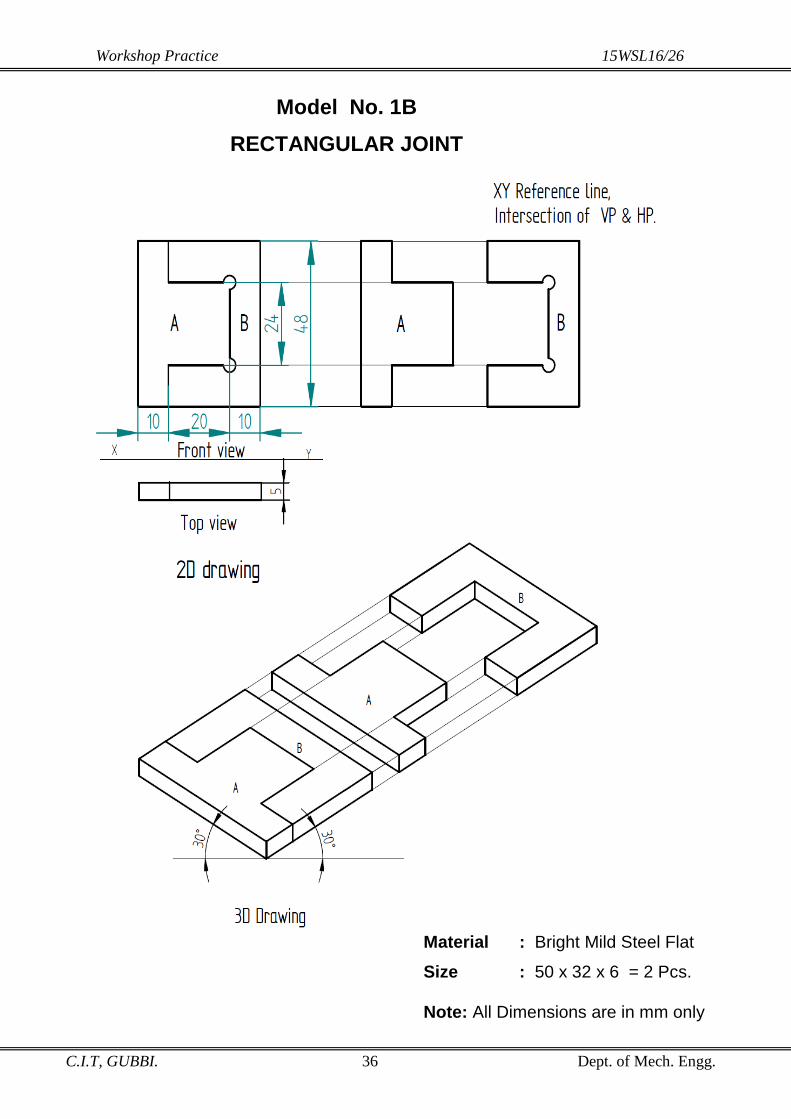
Model No. 1B
RECTANGULAR JOINT
Material : Bright Mild Steel Flat
Size : 50 x 32 x 6 = 2 Pcs. Note: All Dimensions are in mm only

Workshop Practice 15WSL16/26
C.I.T, GUBBI. 37 Dept. of Mech. Engg.
Model No. 2 DOVETAIL JOINT
Material : Bright Mild Steel Flat
Size : 50 x 32 x 6 = 2 Pcs.
Note: All Dimensions are in mm only

Workshop Practice 15WSL16/26
C.I.T, GUBBI. 38 Dept. of Mech. Engg.
Model No. 3 SEMI CIRCULAR JOINT
Material: Bright Mild Steel Flat Size: 50 x 32 x 6 = 2 Pcs.
Note: All Dimensions are in mm only

Workshop Practice 15WSL16/26
C.I.T, GUBBI. 39 Dept. of Mech. Engg.
Model No. 4
STEPPED JOINT
Material : Bright Mild Steel Flat
Size : 50 x 32 x 6 = 2 Pcs.
Note: All Dimensions are in mm only
Workshop Practice 15WSL16/26
C.I.T, GUBBI. 40 Dept. of Mech. Engg.
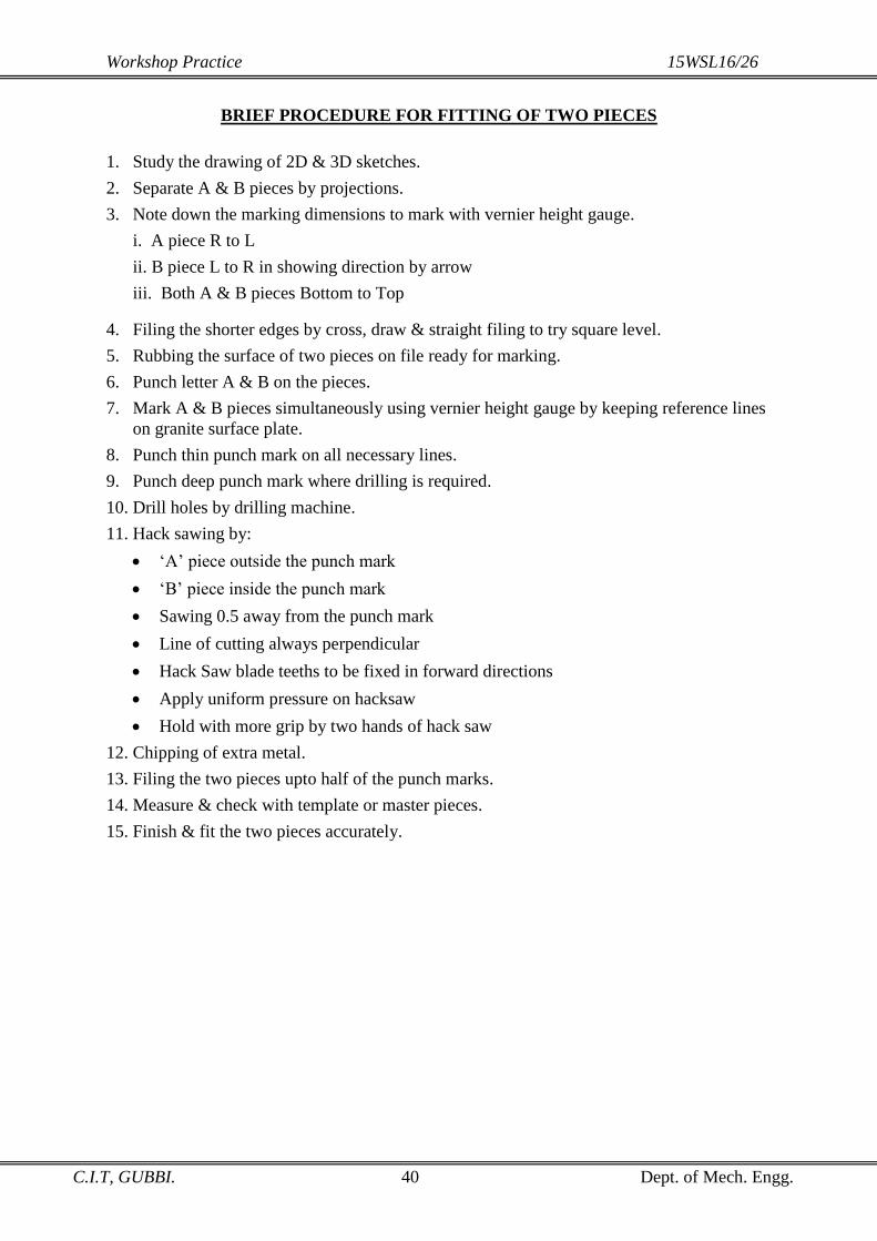
BRIEF PROCEDURE FOR FITTING OF TWO PIECES
1. Study the drawing of 2D & 3D sketches.
2. Separate A & B pieces by projections.
3. Note down the marking dimensions to mark with vernier height gauge.
i. A piece R to L
ii. B piece L to R in showing direction by arrow
iii. Both A & B pieces Bottom to Top
4. Filing the shorter edges by cross, draw & straight filing to try square level.
5. Rubbing the surface of two pieces on file ready for marking.
6. Punch letter A & B on the pieces.
7. Mark A & B pieces simultaneously using vernier height gauge by keeping reference lines
on granite surface plate.
8. Punch thin punch mark on all necessary lines.
9. Punch deep punch mark where drilling is required.
10. Drill holes by drilling machine.
11. Hack sawing by:
‘A’ piece outside the punch mark
‘B’ piece inside the punch mark
Sawing 0.5 away from the punch mark
Line of cutting always perpendicular
Hack Saw blade teeths to be fixed in forward directions
Apply uniform pressure on hacksaw
Hold with more grip by two hands of hack saw
12. Chipping of extra metal.
13. Filing the two pieces upto half of the punch marks.
14. Measure & check with template or master pieces.
15. Finish & fit the two pieces accurately.

Workshop Practice 15WSL16/26
C.I.T, GUBBI. 41 Dept. of Mech. Engg.
SHEET METAL WORK
The process of making shearing, notching, bending, hemming, piercing, blanking,
forming and finally the process of joining involved in making the sheet metal products is
called Sheet Metal Work.
SHEET METAL PROCESS
Study of Drawing.
Development.
Metal Sheets with Gauge Number.
Pattern or Template.
Sheet Metal Operations.
Joining by Soldering, Brazing or Welding.
PRACTICAL APPLICATIONS
Automobiles Industries.
Aircraft Industries.
Shipbuilding.
Packing.
Air Conditioning.
Hoppers.
Tin Containers.
Storage Tanks.
Chimney.
Boilers etc
Development
The complete surface of an object is opened to one plane is drawn on paper provided
with suitable allowances for seam and hem is called Development.
Methods of Developments:
1. Parallel line method of development: The surfaces of right prisms, cylinders, cubes,
Rectangular Trays & Similar objects.
2. Radial line method of development: The lateral surfaces of right pyramids and cones
may be developed by this method.
3. Triangulation method of development: The surfaces are made of a No of Triangular
strips laid out in their true size. Ex. Square to round Rectangular to square etc.
4. Approximate Method of development: This method is used to draw the development
of a sphere etc.
Pattern or Template
It is a metal sheet obtained from development shape is called pattern or template. It is used
for marking repeatedly to get consistency products in mass production work as it saves
valuable time in marking process.

Workshop Practice 15WSL16/26
C.I.T, GUBBI. 42 Dept. of Mech. Engg.
Metal used in sheet metal work
A large variety of metals are used in the form of sheet & plate. The specifications of metal
sheets are given in terms of their gauge numbers and length & width.
The gauge number correspond to thickness of sheet is measured by using standard wire
gauge. The higher the gauge no, the smaller the thickness and vice versa.
Common metal sheets used in Sheet metal work are,
1. BP or H. R sheets (Black Plain or Hot Rolled sheets)
2. CR Sheet(Cold Rolled sheets ) 0.1 – 0.3% carbon
3. G P sheets ( Galvanizing Zinc)
4. Aluminum sheets
5. Copper Sheet
6. Tin sheet
7. Stainless steel sheets ( Alloy Steel it contains 18% of chromium , 8 % Nickel, less
than 1% Carbon the rest is iron)
Gauge number corresponding to thickness of sheet or wire diameter.
Sl.
No. Gauge No
Thickness of sheet or
diameter of wire in mm
1 10G 3.25
2 12G 2.64
3 14G 2.03
4 16G 1.63
5 18G 1.22
6 20G 0.91
7 22G 0.71
8 24G 0.56
9 26G 0.46
10 28G 0.38
11 30G 0.30
Safety precautions in sheet metal shop
1. While working in sheet metal shop be careful with sharp cutting tools and sheet edges.
2. Wear well closed clothing, avoid wrist watches, Rings, Bracelets, necktie etc.
3. While working with screw driver or chisel do not hold small work in your hand.
4. Be cautions while using acids as soldering flux.
5. Testing a soldering copper for correct heat, Touch the heated copper to a solder, solder
begins to flow, the correct temperature as been achieved.

Workshop Practice 15WSL16/26
C.I.T, GUBBI. 43 Dept. of Mech. Engg.
Sheet Metal Operations
1. Measuring: - It is process of measuring length, width and thickness of sheet by using
steel scale, Standard wire gauge, Micrometer etc.
2. Marking: - It is a process of marking the desired shape on a given sheet (G P Sheet
28G) thin punch on line of bending with use of centre punch & Ball peen hammer.
3. Cutting & Shearing: - It is a process of cutting blank. The term shearing stands for
cutting of sheet metal by two parallel cutting edges moving in opposite direction. This
can be done either by hand snip or means of shearing m/c.
4. Notching: - It is a process of removal of excess material from the edge of strip to
avoid wrinkling or bulging to obtain correct shape.
Straight notch - l , Square Notch - ┐, V notch - V
5. Bending: - It is a process of bent the sheet in one plane. (┌)
6. Piercing and Punching: - It is a process in which a pointed bullet shaped punch is
forced enough to produce a hole on sheet. (О),(∩)
7. Nibbling:- It is a process of continuous cutting along a contour which may be a
straight line or on irregular profile is known as Nibbling by potable shearing machine.
8. Hemming:- It is a process of folding the edge of sheet to provide stiffness and safety
on hand for sheet metal products.
9. Seaming: - It is a process of interlocking of sheet metal products such as drums, cans,
bucket, funnel etc.
10. Forming: - It is a process of shaping sheet metal objects to give it desire shape and
size of the final product by using different shapes of stakes. (∆)
11. Planishing: - It is a process of giving good surface finish by Rubber, Nylon &
Wooden Mallets.
12. Swaging: - It is process of making the sheet into a ridge surface or corrugated.
Example: Rolling Shutters, Roof sheets etc.
13. Coining: - Coin, Medal and other similar parts are produced by this process by using
hand press with coining die and punch.
14. Stamping: - It is a process of printing letters, numbers and other figures on metal
using stamping dies and punch. A, B and 1, 2
15. Riveting: - It is a process joining permanent in which the end of the metal pin is
pressed over or spread out by hammering operation.

Workshop Practice 15WSL16/26
C.I.T, GUBBI. 44 Dept. of Mech. Engg.
Hand Tools required to perform Sheet Metal operations in sheet metal work
Sl.
No.
Name of the
Operation Tools Required
1 Measuring 1. Steel Scale,
2. Standard wire gauge, Micrometer/ Vernier Caliper
2 Marking Steel Square, Scriber, Divider, Sketch Pen & Trammel Point
3 Cutting & shearing Hand snip or Tin Cutter, hand Shearing Machine
4 Notching Hand Snip or Tin Cutter.
5 Bending Hand operated Toggle press with suitable punch & Die.
6 Piercing & Punching Hand operated Toggle press with suitable punch & Die.
7 Hemming or Edge
stiffening
Hand operated Toggle press with suitable punch & Die with
mallet
8 Forming Sheet metal stakes of different Shapes
9 Seaming Hand press with Mallet
10 Planishing Planishing hammer made out plastic, nylon, Rubber, Raw
hide Etc
11 Stamping Hand toggle press with top and bottom punch & die.
12 Coining Hand toggle press with top and bottom punch & die.
13 Swaging/ Crimping Hand toggle press with top and bottom punch & die.
14 Soldering Electric soldering iron & nose pliers.
15 Riveting Hand Toggle pressing machine
Sheet Metal Hand tools and accessories
1. Steel scale
2. Steel Square
3. Standard Wire gauge
4. Micrometer
5. Scriber, marker pen
6. Divider , centre punch
7. Trammel point
8. Hand snip or tin cutter, flat chisel
9. Hand operated toggle press with punch & Die
10. Sheet metal stakes of varies shapes
11. Wooden mallet
12. Soldering copper
13. Lever shearing machine

Workshop Practice 15WSL16/26
C.I.T, GUBBI. 45 Dept. of Mech. Engg.
Hand Operated Toggle Press:
Toggle press is used for performing sheet metal operations by using different press
tools. (Punch & Die)
Operations performed are,
1. Bending
2. Punching and piercing
3. Notching
4. Stamping
5. Shearing, Riveting, Crimping, Coining, Straitening etc.
Main Parts
1. A rigid C.I FRAME with bed providing holes for mounting press tools.
2. A RAM which exerts force upon work piece through a punch and die mounted on ram
and bed respectively.
A linear movement to the ram is transferred by the energy stored in toggle joint operated
by offset hand lever (600kg)
3. Toggle Joint
4. Offset hand lever
5. Spring loaded return motion
6. Punch and die
Objective Type Questions
Fill in the blanks/ Say Yes or No
1. The thicknesses of sheet are measured in ___________________ number.
2. The higher the gauge numbers the large the thickness and vice versa. ( )
3. The steel rule is particularly useful in measuring and laying out small work. ( )
4. Steel square is employed for checking and marking ____________ angles.
5. _____________ is also known as metal worker pencil.
6. Trammel points are used for drawing large circles and arcs that are beyond the limit of
dividers.( )
7. ______________ Stake has a tapered round working sheet.
8. A mallet is used for smoothing the sheets. ( )
9. Piercing is basically a hole punching operation. ( )
10. All lines of a development must be true length. ( )

Workshop Practice 15WSL16/26
C.I.T, GUBBI. 46 Dept. of Mech. Engg.

Workshop Practice 15WSL16/26
C.I.T, GUBBI. 47 Dept. of Mech. Engg.
Sequence of operation or Procedure to prepare Trays in Sheet metal.
Draw 2D/ 3D sketches as per scale.
Draw the development considering all lines must be a “ True Length”
Construct the base of the Tray.
Construct the two sides of the tray.
Construct the two ends of the tray.
Set 5mm extra, allowance on side face for joining the corners by seaming.
Notch the points to prevent bulging on seaming
Cut the development shape on lines by using paper cutting scissor
Place and fix the development on given G.P sheet by using Sticker.
Punch two points on each bending line.
Mark the boundary line by using Marking Pen.
Remove the paper development join the two punch points by a scriber or marking
pen.
Shear the boundary lines by hand snip.
Flattening the sheet by using mallet on flatter.
Always bend the seaming line first and remaining lines to get the desired shape by
forming.
Finish the surface keeping on stake to shape.
Solder the joint.
Finish surface finishing and complete the Tray.
Single Hem Double Hem Single Lap Seam
Making a Wired Edge
Making a Grooved Seam
Making a Double Seam
Dovetail Seam Joint
HEMS AND SEAMS

Workshop Practice 15WSL16/26
C.I.T, GUBBI. 48 Dept. of Mech. Engg.

Workshop Practice 15WSL16/26
C.I.T, GUBBI. 49 Dept. of Mech. Engg.
HEXOGONAL PRISM
CONSTRUCTION OF REGULAR HEXAGON OF SIZE 25MM SIDE.
Draw a line ab equal to 25mm.
From a & b draw a line 120o to af and bc.
Draw arc from a and b with radius equal to 25mm on them to get f and c respectively.
From c draw a line parallel af cut the arc of radius 25mm on it to get d.
From d draw a line parallel to ab and cut an arc of radius 25mm on to get e join ef and complete
the hexagon.
Locate the centre by joining any two diagonals say ad and be.
TO DRAW DEVELOPEMNT(PARALLEL LINE METHOD):
Draw the top view and Front view of the prism of the given dimensions.
Draw a stretch at line AA’ equal to 150mm.
Mark off the sides 25x6=150mm.i.e; AB,BC,CD ,DE,EF and FA each side 25mm.
Erect perpendicular through this point and mark the edges AA’,BB’,CC’,DD’,EE’,FF’ at a height
50mm.
Add 5mm extra adjacent to AA’ for seaming.
WORKING STEPS TO PERFORM THE PRISM:
Cut the development to shape on lines by using paper cutting scissor.
Place and fix the development on given G.P sheet by using sticker.
Punch two thin punch mark on each bending line.
Mark all bending and boundary line with scriber on that marking pen with reference to paper
development.
Shear the boundary line by Hand snip or Toggle press shearing machine.
Flatten the sheet by using mallet and flattener.
Always bend the seaming line first then the remaining lines to get the desired lines.
Form the shape by hexagonal stake to shape.
Solder the joints.
Finish the surface finishing and complete the job.
TO DRAW ISOMETRIC VIEW OR DRAWING OF HEXAGONAL PRISM:
The Hexagonal prism in the top view is enclosed in a rectangular box 1234.
Draw isometric drawing of this rectangular box by setting 300
on each side named as 1234 as
shown in the sketch.
On line 1,2 mark AB with reference to top view.
On line 2,3 mark C with reference to top view..
On line 3,4 mark DE with reference top view.
On line 4,1 mark F with reference top view.
Join AB,BC,CD,DE,EF and FA.
From points ABCDEF draw a perpendicular equal to height of hexagonal prism 50mm named as
A’B’C’D’F’.
Join AA’,BB’,CC’,DD’,EE’,FF’.
Join A’B’,B’C’,C’D’,D’E’,E’F’ and F’A’.
Complete the isometric drawing of hexagonal prism drawn by thick line.

Workshop Practice 15WSL16/26
C.I.T, GUBBI. 50 Dept. of Mech. Engg.

Workshop Practice 15WSL16/26
C.I.T, GUBBI. 51 Dept. of Mech. Engg.
PENTAGONAL PRISM
CONSTRUCTION OF REGULAR PENTAGON OF SIZE 30 MM SIDE
Draw a line ab equal to 30mm.
From a and b draw a line at 108o to ab.
With centre a & b radius equal to 30mm draw an arc to get ce.
With centre c & e radius equal to 30mm draw arcs to get the intersection point ‘d’.
Join line cd & de to complete the pentagon.
From any two corners draw perpendicular to opposite side.
The intersection point locate the centre.
TO DRAW DEVELOPEMNT(PARALLEL LINE METHOD) :
Draw the top and front view of the prism from the given dimensions.
Draw a stretch line AA’ equal to 150mm.
Mark off the sides 30x5=150mm.i.e; AB, BC, CD, DE and EA each side 30mm.
Erect perpendicular through this point and mark the edges AA’, BB’, CC’, DD’, EE’, AA’ at an
height of 50mm.
Add 5mm extra adjacent to AA’ for seaming.
WORKING STEPS TO PERFORM THE PENTAGONAL PRISM.
Cut the development to shape on lines by using paper cutting scissor.
Place and fix the development on given G.P sheet by using sticker.
Punch two thin punch mark on each bending line.
Mark all bending and boundry lines with scriber on that again with marking pen with reference to
paper development.
Shear the boundry line by Hand snip or Toggle press shearing attachment.
Flatten the sheet by using mallet and flatteners.
Always bend the seaming line first then the remaining lines to get the desired shape.
Form the shape by pentagonal stake.
Solder the joints.
Finish the surface finishing and complete the job.
TO DRAW ISOMETRIC VIEW OR DRAWING OF PENTAGONAL PRISM
The pentagonal prism in the top view is enclosed in a rectangular box 1234.
Draw isometric drawing of this rectangular box by setting 300
on each side named as 1234 as
shown in the sketch.
On line 1,2 mark AB with reference to top view.
On 2,3 mark C with reference to top view..
On line 3,4 mark D with reference top view.
On line 4,1 mark E with reference to top view.
Join AB,BC,CD,DE, and EA.
From points ABCDE draw a perpendicular equal to height of pentagonal prism 50mm named as
A’B’C’D’E’.
Join AA’,BB’,CC’,DD’,EE’.
Join A’B’,B’C’,C’D’,D’E’ and E’A’.
Complete the isometric drawing of pentagonal prism drawn by thick line.

Workshop Practice 15WSL16/26
C.I.T, GUBBI. 52 Dept. of Mech. Engg.
Model No. 3
Material : G.P. Sheet 28 G

Workshop Practice 15WSL16/26
C.I.T, GUBBI. 53 Dept. of Mech. Engg.
SEQUENCE OF OPERATION TO PREPARE TRAY AND DUSTPAN IN SHEET METAL
Draw 2D/3D sketch as per scale.
Draw the development considering all lines must be “TRUE LENGTH”.
Construct the base of the Tray/Dust pan.
Construct the two sides of the Tray /Dust pan.
Construct the two ends of the Tray or Dust pan.
Set 5mm extra allowance on side face for joining the corners by seaming.
Notch the point to prevent bulging in seaming.
Cut the development shape on lines by using scissor.
Place and fix the development on given G.P sheet by using Sticker.
Punch two thin points on each bending line.
Mark the boundary lines and bending lines with scriber and again mark with marking pen for
visible.
Shear the boundary line with hand snip or shearing machine.
Flatten the sheet by using the mallet on flatter.
Always bend seaming line first then the remaining lines to get the desired shape.
Perform the forming operation with using suitable stake.
Solder the joints.
Finish the surface finishing and complete the Tray or Dustpan.
Model No. 4
Material :
G.P. Sheet 28 G

Workshop Practice 15WSL16/26
C.I.T, GUBBI. 54 Dept. of Mech. Engg.

Workshop Practice 15WSL16/26
C.I.T, GUBBI. 55 Dept. of Mech. Engg.
TAPERED TRAY
I. To draw orthographic and isometric drawing as shown in the sketches.
II. To Draw The Development:
Draw the front view of the Tray as shown in the sketch.
With centre ab radius equal to ae, bf draw an arc to reach horizontal line at R & S.
Draw the XY reference line.
Project lines from front view R & S, e& f, a & b to top view.
Construct the base of the Tray ABCD 35x60mm from the centre of the reference line
draw below XY line.
Construct the two ends of the Tray ie, 35x50mm ie, BCFG & ADEH.
With centre ABCD radius equal to AE BF CG DH draw an arc to intersect at EFGH
on the projected line R, S.
Join EF HG AE BF CG DH which will be two sides of the tray.
Add extra 5mm for seam in all corners with Notching.
III. Working steps to perform the tapered tray
Cut the development to shape on lines by using paper cutting scissor.
Place and fix the development on given G.P sheet by using sticker.
Punch the two points on each bending lines.
Mark boundary line & bending line using scriber.
Remove the paper development.
Cut or Shear the boundary line by Hand snip or Toggle press (Shearing attachment).
Flatten the level of sheet by using mallet and flattener.
Always bend the seaming line first then the reaming lines to get the desired lines.
Perform Bending, forming, hemming on Tapered tray stakes.
Solder the joints.
Finish the surface finishing and complete the job.

Workshop Practice 15WSL16/26
C.I.T, GUBBI. 56 Dept. of Mech. Engg.
Model No. 6

Workshop Practice 15WSL16/26
C.I.T, GUBBI. 57 Dept. of Mech. Engg.
FRUSTUM OF CONE / FUNNEL
TO DRAW THE DEVELOPMENT OF FRUSTUM OF CONE/FUNNEL-
RADIAL LINE METHOD
Draw the front view of the right circular cone ab of base diameter is 60mm.
A section plane cuts perpendicular to the axis of the cone at 40mm height at cd above
the base.
With o as the centre & radius equal to slant generator oa or ob draw an arc. With same
center o is radius equal to oc or od draw another arc.
Find ɵ = 360x r where ɵ-Angle substended to cut the arc.
R r- Base radius of the cone ab/2.
R- Slant generator of the cone oa or ob.
Set an angle ɵ -161° at the point of vertex to cut the arc at point EFGH set 4 & 4+4 mm
extra on each end for seam joint.
The development of the Part II is in the same concept of Part I.
TO DRAW THE ISOMETRIC VIEW OR DRAWING OF A
(Funnel Four Centre Arc Method)
Enclose the circle in square abcd with mid points 1234 as shown in sketches.
Draw a rhombus ABCD to represents isometric view of the actual square abcd mark mid points
1234 as shown in sketches.
Connect the diagonal AC & BD is the Isometric view.
With centre A & C radius equal to A3, C1 respectively draw an arc.
Connect C1 & C4 intersect the diagonal BD at O1 & O2
With centre O1 & O2 radius equal to O1 3 & O2 1 respectively, draw an arc to complete the ellipse.
Find the mid-point O in the ellipse measure 40mm height of the frustum of the cone to represents
ø20mm.
Construct another free hand ellipse of ø20mm.
Extended 35mm height from the mid-point of ø20mm ellipse for 2nd
part of the funnel.
Construct another free hand ellipse of ø10mm to complete the Isometric view of the funnel.
Note: The view drawn to the actual scale is called isometric view or Drawing
The view drawn using Isometric scale is called Isometric projection (0.816).
i. It is time consuming.
ii. Isometric axis cannot be measured with actual scale.
WORKING STEPS TO PERFORM THE FUNNEL
Trace the paper development on GP sheet.
Mark all boundry line with scriber.
Shear the sheet by hand snip according to shape of the development in one stroke.
Fold 4mm extra allowance in clockwise & anticlockwise direction by keeping hacksaw
blade thickness & pressed.
Remove the hacksaw blade Bend the main body using on cone stack & lock the end
joints.
Repeats the same to part No2.
Finally solder the two parts with perfect alignment.

Workshop Practice 15WSL16/26
C.I.T, GUBBI. 58 Dept. of Mech. Engg.
Workshop Practice 15WSL16/26
C.I.T, GUBBI. 59 Dept. of Mech. Engg.
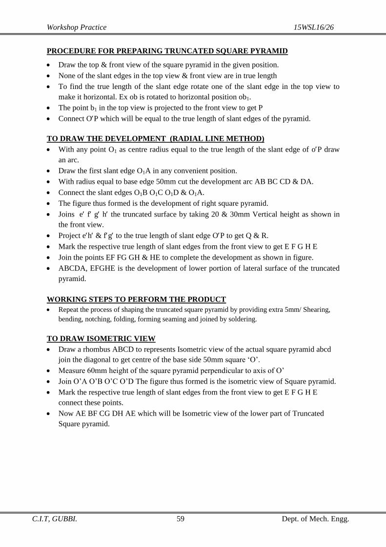
PROCEDURE FOR PREPARING TRUNCATED SQUARE PYRAMID
Draw the top & front view of the square pyramid in the given position.
None of the slant edges in the top view & front view are in true length
To find the true length of the slant edge rotate one of the slant edge in the top view to
make it horizontal. Ex ob is rotated to horizontal position ob1.
The point b1 in the top view is projected to the front view to get P
Connect OP which will be equal to the true length of slant edges of the pyramid.
TO DRAW THE DEVELOPMENT (RADIAL LINE METHOD)
With any point O1 as centre radius equal to the true length of the slant edge of oP draw
an arc.
Draw the first slant edge O1A in any convenient position.
With radius equal to base edge 50mm cut the development arc AB BC CD & DA.
Connect the slant edges O1B O1C O1D & O1A.
The figure thus formed is the development of right square pyramid.
Joins e f g h the truncated surface by taking 20 & 30mm Vertical height as shown in
the front view.
Project eh & fg to the true length of slant edge OP to get Q & R.
Mark the respective true length of slant edges from the front view to get E F G H E
Join the points EF FG GH & HE to complete the development as shown in figure.
ABCDA, EFGHE is the development of lower portion of lateral surface of the truncated
pyramid.
WORKING STEPS TO PERFORM THE PRODUCT
Repeat the process of shaping the truncated square pyramid by providing extra 5mm/ Shearing,
bending, notching, folding, forming seaming and joined by soldering.
TO DRAW ISOMETRIC VIEW
Draw a rhombus ABCD to represents Isometric view of the actual square pyramid abcd
join the diagonal to get centre of the base side 50mm square ‘O’.
Measure 60mm height of the square pyramid perpendicular to axis of O’
Join O’A O’B O’C O’D The figure thus formed is the isometric view of Square pyramid.
Mark the respective true length of slant edges from the front view to get E F G H E
connect these points.
Now AE BF CG DH AE which will be Isometric view of the lower part of Truncated
Square pyramid.

Workshop Practice 15WSL16/26
C.I.T, GUBBI. 60 Dept. of Mech. Engg.
WELDING
It is a process of joining two pieces of metals by heating them to a suitable temperature with
addition of filler metal or with application of pressure is called Welding.
Welding Process
Study of Drawing.
Setting of Arc Welding Plant.
Current Setting and Selection of Electrode.
Striking and Maintaining the Arc.
Tack Welding using Suitable Fixture.
Bead Welding using Suitable Fixture.
Chipping of Slag with Spectacles.
Clean the Bead by Wire Brush with Spectacles.
Practical application of welding:
Automobile Industries.
Railway Industries.
Ship Building.
Air Craft Industries.
Machine Tool Industries.
Repair Works.
Fabrication of all Metal Structures and Towers.
Now a day there is no industry which is not using welding process in the fabrication
of its products in some form or the other.
Advantage of welding process when comparing with other process of manufacturing.
Welding is the most acceptable method of fabrication for the following reasons
1. This is the most rapid and easiest way of fabrication and assembly of metal parts.
2. 10 to 40% material can be saved and weight reduction.
3. This process having more than 100% strength of the joint.
4. Greater flexibility in fabrication and erection.
5. Repair and maintenance is easier.
6. Better integrity of components.
Classification of welding:

Workshop Practice 15WSL16/26
C.I.T, GUBBI. 61 Dept. of Mech. Engg.
1. Fusion welding: The pieces of metals to be joined are heated to molten/liquid state with
addition of filter metal used during welding process and allowed to solidity. Eg. Arc
welding, Gas welding.
2. Plastic welding :The pieces of metal to be joined are heated to plastic// red hot! state with
application of pressure. E.g. Forge welding, Resistance welding.
ARC WELDING: The pieces of metal
to be joined are heated to molten or liquid
state by an electric arc with using flux
coated consumable electrode. The intense
heat of the electric arc will melt the work
pieces and electrode. This molten pool will
make a welding joint after solidification.
This process of is mostly used for welding
ferrous metals.
GAS WELDING: The pieces of metal
to be joined are brought to melting
temperature from OXY-acetylene flame
and then weld is completed by addition of
filler metal (Gas welding rods). The
process of welding is used for joining non-
ferrous metal and small / thin sections.
FORGE WELDING: The pieces of
metal to be joined are heated to plastic
state from coal/leco/charcoal/ in hearth or
forge then pressing together by hand
power hammering.
This is the oldest method of welding.
This process is used in block smith
shop for joining wrought iron and low
Carbon Steel.

Workshop Practice 15WSL16/26
C.I.T, GUBBI. 62 Dept. of Mech. Engg.
RESISTANCE WELDING:
In resistance welding a heavy electric
current is passed through the metal to be
joined over a limited area causing them to
be locally heated up to. Plastic state and
weld is completed by the application of
pressure for a prescribed period of time.
No addition of filler metal is required.
Resistance welding is employed mainly for
mass production. This is the only process
where heat can be controlled and which
permits a pressure action at the weld. The
operation is extremely rapid and simple.
E.g. Spot welding, Butt Welding, Seam
welding etc.
Arc Welding and its equipments:
When two conductor of an electric circuit of very high current and low voltage
(approximately 200 amps, 20 Volts) are connected with one to flux coated consumable
electrode and other one to work piece are brought nearer touch and separated in a small
distance of about 4 mm an electric arc is formed. The electric arc is protected from out side
atmosphere with gaseous shield around the arc from flux-coated electrode. The temperature
of arc is about 3000 to 4000°C. The heat of an electric are will melt the work pieces and
electrode. This molten pool will make a welding joint after solidification from the
atmosphere. Ensure safety apparel is worn.
Arc welding equipments:
1) AC or DC machines
2) Welding cable and its connectors
3) Electrode holder
4) Earthling clamps
5) Face shield or helmet
6) Goggles and spectacles.
7) Leather hand gloves.
8) Apron.
9) Chipping hammer and wire brush
10) Tongs.

Workshop Practice 15WSL16/26
C.I.T, GUBBI. 63 Dept. of Mech. Engg.
Safety precautions in Arc Welding:
Because of the intensity of heat and light rays from the electric arc the operator hands, face,
and eyes are to be protected while the arc is in use. Leather hand gloves are ‘worn and a hand
shield or a helmet with a window of colored glass should be used to protect the face and eyes
from the glaring effect of the arc rays. Also the space for the electric arc welding should be
screened off from the rest of the building to safe guard other workmen from the glare of arc.
Related applications of AC and DC welding:
AC Welding DC Welding Ac welding is a low cost efficient
performance and popular to weld heavy gauge
steel finds maximum use.
DC welding is best suitable for thinner,
sheet metals and non-ferrous metals.
Best suitable for flat and horizontal position of
welding
DC welding has a greater use in overhead
and vertical position.
The biggest advantages in AC welding
i) Complete absence of magnetic arc blow
(deflection arc is called arc blow)
ii) Arc is forceful and produces good
penetration. (Pierce or deep in sight)
TIG and MIG welding etc.
It is easier to strike and maintain a stable
arc. Polarity can be changed to +ve and -ve
to electrode
Base wire and light coated electrode can be
Easily used.
Skill Information required to perform various functions in an Electric Arc
Welding to produce good Arc welding joints.
1. Setting of arc welding plant.
2. Setting of welding current and selection of electrode according to plate thickness.
3. Strike and maintain the arc.
i. Scratching method.
ii. Tapping method
4. To deposit straight bead in a flat position.
i. Electrode position.
ii. Depositing straight beads by maintaining;
a. Correct arc length.
b. Correct travel speed.
c. Correct angle of electrode.
5 Clean the weldment and inspect for faults.
i. Remove the slag using chipping hammer and wire brush.
ii. Inspect the deposited bead.

Workshop Practice 15WSL16/26
C.I.T, GUBBI. 64 Dept. of Mech. Engg.
1. Setting of arc welding plant.
Check the working of power source for the welding
machine.
Remember electricity is a good servant but a bad
master.
Call an electrician for solving any electrical problems.
Connect the welding cables with the welding machines.
Ensure that the cable connections are clean, dry,
tight and are attached to the proper terminals of the
machine.
Attach tightly the earth cable with the welding table
at the proper place.
Keep the electrode-holder at a safe place.
If the machine is on D.C. power connect the cables in
correct polarity.
Polarity means changing of +ve and -ve to the electrode
is called polarity.
2. Current setting & selection of electrode according to
the thickness of plate to be joined.
Set the welding current and select the electrode as per the
thickness of the metal to be welded ref table.
Use alternative electrodes of nearest size in the case of
non-availability of the exact size of electrodes.
The electrode diameter should not be more than the
thickness of the metal to be welded.
Set the current on the welding machine 120-130 amps for
3.15mm M.S. electrode. If the thickness of metal to be welded is 5mm. Always follow the
current range chart for the electrodes in use.
3. Striking and maintaining an Arc.
Striking an arc is a basic operation in arc welding. It will occur every time the
welding is to be started. It is an essential basic skill to learn in arc welding.
i) Scratching method:
Hold the electrode about 25 mm above the job piece at
one end perpendicular to surface
Bring the welding screen in front of your eyes.
Ensure safety apparatus is worn.
Strike the arc by dragging the electrode quickly and softly
across the welding job, using wrist movement only.
Withdraw the electrode approximately 6 mm from the surface for a few seconds and then
lower it to (approximately) 4mm distance.
If the arc has been properly struck, a burst of light with a steady sharp crackling sound
will be produced.

Workshop Practice 15WSL16/26
C.I.T, GUBBI. 65 Dept. of Mech. Engg.
ii) Tapping method:
Strike the arc by moving the electrode down to
touch the job surface lightly.
Move the electrode slowly up approximately 6mm
for a few seconds and then lower it to
approximately 4 mm from the surface.
The tapping method is generally recommended as it
does not produce pit marks on the job surface
4. To deposit straight bead in a flat position.
i. Job setting
* Set the job in a flat position on the welding table.
* Ensure there is good electrical contact between the
job and the welding table.
ii. Electrode position
* Hold the electrode at an angle of 70o-80
o with the weld line and 90
o with the
adjoining plate surface.
BRIEF PROCEDURE FOR ARC WELDING
1. Set the arc welding plant by one cable connection to electrode with electrode holder another
connection for workpiece with earthing clamp.
2. Set the current range & electrode according to plate thickness.
Ex: 6mm plate i) Current range 120Amps
ii) Electrode size 3.2mm Dia or 10G
3. Set the workpiece for tack weld by fixing with C Clamp using suitable tack welding fixture.
4. Tack the pieces at both ends by scratching or tapping method.
5. Place the tack weld unit to full bead welding fixture as provided in working table.
6. Deposits full bead weld with correct i) Arc lengths 3 to 5mm ii) Electrode angle 700
to 80o
iii)
Travel speed 150mm/min iv) uniform Movement v) Direction towards your end.
7. Reverse the joint to perform full bead on other end.
8. Chip off all slag, remove spatters with using white spectacles
9. Clean the bead by wire brush with using white spectacles.
10. Inspect the weld bead.
Why Electrodes are coated?
During welding, the work pieces melts and at the same time, the tip of electrode also melts.
As the globules of molten metal pass from the electrode to the work piece, they absorb
Oxygen and Nitrogen from the atmospheric air. This causes the formation of some non-
metallic constituents that are trapped in the solidifying weld metal thereby decreasing the
strength of the welded joint. In order to avoid this, a flux is coated on the metallic wire.
During welding, the flux vaporizes and produces a gaseous shield around the molten weld
pool. The flux also performs a variety of functions depending on the constituents from which
it is made.

Workshop Practice 15WSL16/26
C.I.T, GUBBI. 66 Dept. of Mech. Engg.
Advantages of coated electrodes:
1 Stabilizes the arc.
2. Prevents oxidation of molten metal
3 Helps in removal of oxides and other undesirable substances present on the surface of the
work piece.
4. Chemically reacts with the oxides and forms a slag. The slag floats and covers the top
portion of the molten metal thereby preventing it from rapid cooling.
5. Reduces weld metal porosity.
6. Helps to produce minimum spatter adjacent to the weld
Comparison of Basic Jointing Processes
WELDING BRAZING SOLDERING
Definition
It is a process of jointing
two or more pieces of
similar or dissimilar
metals by heating them to
a suitable temperature
with or without addition
of filler metal
It is a process of joining
two or more pieces of
metal with the help of
some fusible alloy
known as ‘spelter’
having its melting point
above 600°C but lower
than the melting point of
the parts to be joined
It is a process of joining
two or more pieces of
metal with the help of
lower melting point
alloy known as ‘solder’
which has lower
melting point than the
metals being jointed.
Melting
temperature
Both base metal and filler
metal having the same
melting temperature
above 1200°C
Melting temperature of
spelter is from 600°C to
850 °C
Melting temperature of
solder is from 150°C to
350°C
Filler metal
Electrode
(Mild steel, cast Iron,
stainless steel, carbon
etc.)
Spelter
An alloy of copper and
zinc 60% and 40% An
alloy of silver copper and
zinc, 34%, 50% and16%.
Solder.
An alloy of lead and tin
50% and 50%
Source of
heat
Electric arc, gas and
chemical reaction etc.
By torch, furnace,
electric resistance,
immersion etc.
By electric current, coal
fire, gas etc.
Fluxes
Minerals, lime stone or
calcium carbonate, wood
pulp, sugar starch, ball
clay, asbestos, iron
powder, Ferro
manganese, mica etc.
Borax Zinc chloride
Ammonium chloride
Practical
application
1. Automobile industries
2. Aircraft Industries
3. Railway Industries
4. Ship Industries
5. Machining tool
industries
6. Repair works
7. Structural works
1. Evaporator coils
2. Motor cycle parts
3. Aircraft propellers
4. Joining of dissimilar
metals
5. Joining of pipes
1. Sheet metal works
and tin containers
(biscuit, cake, oil,
kerosene, paint tins
etc.)
2. Electrical junctions
3. Joining of electronic
parts etc.
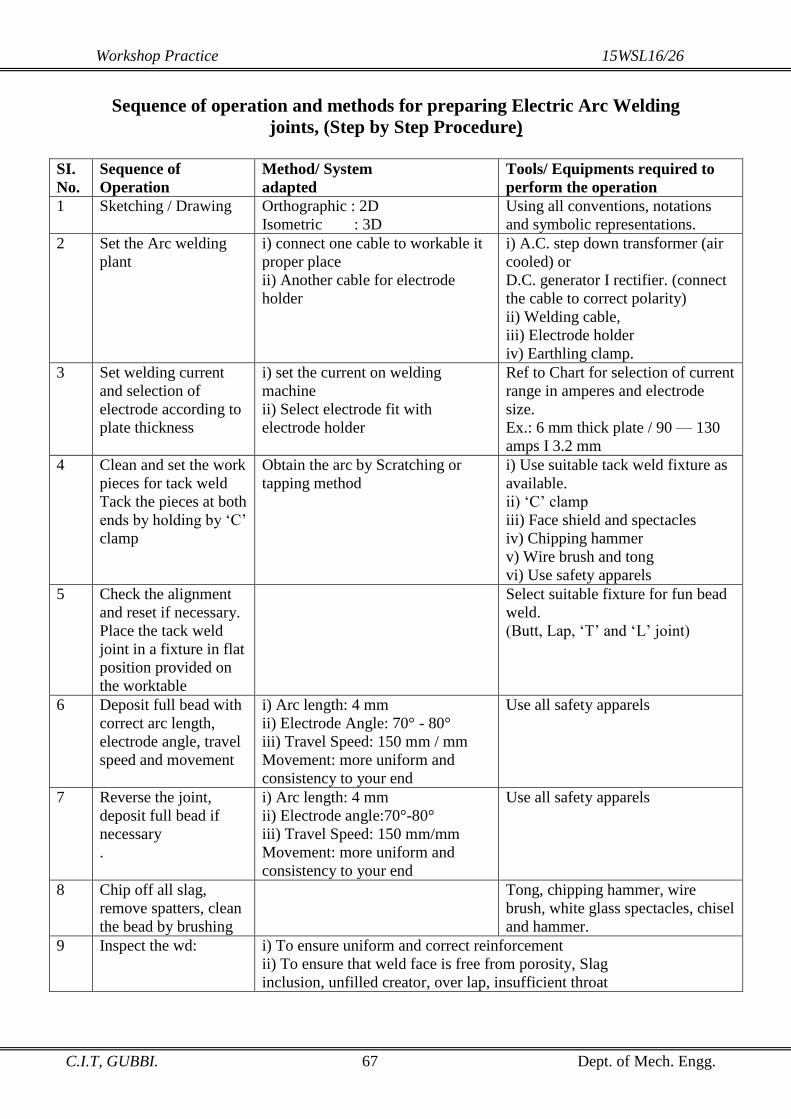
Workshop Practice 15WSL16/26
C.I.T, GUBBI. 67 Dept. of Mech. Engg.
Sequence of operation and methods for preparing Electric Arc Welding
joints, (Step by Step Procedure)
SI.
No.
Sequence of
Operation
Method/ System
adapted
Tools/ Equipments required to
perform the operation
1 Sketching / Drawing Orthographic : 2D
Isometric : 3D
Using all conventions, notations
and symbolic representations.
2 Set the Arc welding
plant
i) connect one cable to workable it
proper place
ii) Another cable for electrode
holder
i) A.C. step down transformer (air
cooled) or
D.C. generator I rectifier. (connect
the cable to correct polarity)
ii) Welding cable,
iii) Electrode holder
iv) Earthling clamp.
3 Set welding current
and selection of
electrode according to
plate thickness
i) set the current on welding
machine
ii) Select electrode fit with
electrode holder
Ref to Chart for selection of current
range in amperes and electrode
size.
Ex.: 6 mm thick plate / 90 — 130
amps I 3.2 mm
4 Clean and set the work
pieces for tack weld
Tack the pieces at both
ends by holding by ‘C’
clamp
Obtain the arc by Scratching or
tapping method
i) Use suitable tack weld fixture as
available.
ii) ‘C’ clamp
iii) Face shield and spectacles
iv) Chipping hammer
v) Wire brush and tong
vi) Use safety apparels
5 Check the alignment
and reset if necessary.
Place the tack weld
joint in a fixture in flat
position provided on
the worktable
Select suitable fixture for fun bead
weld.
(Butt, Lap, ‘T’ and ‘L’ joint)
6 Deposit full bead with
correct arc length,
electrode angle, travel
speed and movement
i) Arc length: 4 mm
ii) Electrode Angle: 70° - 80°
iii) Travel Speed: 150 mm / mm
Movement: more uniform and
consistency to your end
Use all safety apparels
7 Reverse the joint,
deposit full bead if
necessary
.
i) Arc length: 4 mm
ii) Electrode angle:70°-80°
iii) Travel Speed: 150 mm/mm
Movement: more uniform and
consistency to your end
Use all safety apparels
8 Chip off all slag,
remove spatters, clean
the bead by brushing
Tong, chipping hammer, wire
brush, white glass spectacles, chisel
and hammer.
9 Inspect the wd: i) To ensure uniform and correct reinforcement
ii) To ensure that weld face is free from porosity, Slag
inclusion, unfilled creator, over lap, insufficient throat

Workshop Practice 15WSL16/26
C.I.T, GUBBI. 68 Dept. of Mech. Engg.
Experiment No: - 1 Experiment No: - 2
Butt Joint Lap Joint
Lap Joint
Tack welding
Tack welding
Full Bead welding
Full Bead welding
A
B
A
B
A B
B A
B
A
A B
B
A
A B

Workshop Practice 15WSL16/26
C.I.T, GUBBI. 69 Dept. of Mech. Engg.
Experiment No: - 3 Experiment No:-4
Tee Joint V Joint
Tack Welding
Tack Welding
Full Bead Welding
Full Bead Welding

Workshop Practice 15WSL16/26
C.I.T, GUBBI. 70 Dept. of Mech. Engg.
QUESTIONNAIRE
Fill the questionnaire for state of learning in workshop practice.
1. Converting the natural resources for the benefit of mankind is called ______
2. _______ is a person having always creative thoughts & idea's to develop the technology for
the noble cause of the society or nation.
3. _______ is a place of work for preparing varieties of product by using Hand Tools, Machine
Tools & Instruments.
4. The information required to prepare the product are: i. ________ ii. ______ iii. _____
5. is a process of removing unwanted materials with the help of tools from a given stock for
making a component.
6. The shape is formed by pouring molten metal into a mould is called __________
7. The shape is formed by mechanically pressing or hammering in both hot and cold condition is
called _______________
8. The shape formed by various machining operations by machines is called_______.
9. The process of making the product from pieces by joining is called_________.
10. The process of finding the dimensions of the work piece by using calipers, micrometer, and
gauge is called________ (Marking, Punching, Chipping, Measuring)
11. Ferrous Metal contains _________. (Steel, Tungsten, hon, Zinc)
12. Steel is an alloy of __________ & _________(Iron & Carbon, Carbon & Steel, Steel & Iron)
13. _________ is not a Metal. (Iron, Mild Steel, Stone, Cobalt)
14. Iron containing metals are called ________( Non Metals, Ferrous Metals, Non ferrous metals)
15. Devices which are to use to perform work by hand are called (Machine Tools, Measuring
Tools, Hand tools)
16. Devices which are to use to perform the work by Machine are called___________.
(Measuring tools, machine Tools, Grinding Tools)
17. The operation of making series of dents on the marked lines is called ___________.
18. The operation of Producing a holes is called________
19. The operation of smoothening the inner surface of drilled hole is called _______.
20. The operation of enlarging the size of previously drilled hole is called _______.
21. The operation of increasing the size of the hole at one end through a small depth is called _____.
22. The operation of cutting flat, round rods, pipes are called_______.
23. The operation or removing thick layer of metal is called_______.
24. The operation of removing thin layer of metal is called _______.
25. The operation of cutting internal threads is called_______.
26. The operation of cutting external threads is called_______.
27. The process of removing metal using grinding wheel is called _______.
28. Least count of Vernier Caliper is_______mm.
29. Least Count of Micrometer is _______ mm.
30. Vernier Caliper Contains__________ & __________ scale.
31. Vernier Caliper Value of 1 VSD is _________ mm.
32. Micrometer contains ____________ & _________ scale.
33. Least count of Vernier Height Gauge is ________ mm.
34. Pitch of the Micrometer is ________mm.

Workshop Practice 15WSL16/26
C.I.T, GUBBI. 71 Dept. of Mech. Engg.
35. A process of joining 2 pieces of metal by heating then to a suitable temperature with additions
of filler metal with pressure is called _______ (Fitting, Welding' Drilling' Hack sawing)
36. ___________ welding, metals are heated up to plastic state
37. Melting temperature of welding is-.(10000,14000,12000,13000)
38. Melting temperature of Btazing are (5000 to 6000, 6000 to 850o, 850o to 900o)
39. Melting temperature of soldering is (200o to 300o, 350o to 900o, 150o to 350o)
40. Filler metal of welding is called as________.
41. Filler metal of brazing is called as ________.
42. Filler metal of soldering is called as _______.
43. _______ is the first sequence of operation for fitting. (Drawing, Punching, Marking, Filing.
44. _______ is the last sequence of operation for fitting.(Filing, Chipping, Measurements'
Drawing)
45. Why the electrodes are coating flux i)__________ ii) __________ iii) __________
46. Visible lines are drawn in continues line. (Thin, Thick)
47. Dimensioning line projection lines are drawn in _____________ lines. (Thin, Thick)
48. All hand cutting tools are made by ________steel. (Mild Steel, Hi Carbon, Steel, Stainless
Steel)
49. Stainless steel contains _____,_____,_____ & _____.
50. High Speed steel used for ________(Hand Cutting Tool, Fast Cutting Tool & Woodcutting
Tool)
51. Heating & cooling of metal in order to change the property is called __________.
52. Filing methods are ________, __________ & _______.
53. Drilling is an operation making for round holes with_________.(Reamer, Drill Bit, Hammer)
54. Sheet is cut to the particular shape, which is formed by development of surfaces and than
after notching' bending and forming appropriately is finally joined by soldering / welding is
called ______.
55. The complete surface of an object is opened to one plane is drawn on paper provided with
suitable allowances for seam and hem is called _______.
56. The whole surfaces of right prisms, cylinders and cubes are prepared by _________method.
57. The whole surfaces of right circular cone' pyramids are prepared by ________ method.
58. Name some of the products manufactured in sheet metal industry.
59. Name some of common sheets used in sheet metal shop.
60. Hand snip / Tin Cutter are used for _________ operation.
61. Toggle Press is used for____________ operation.
62. Stakes are used for_________ operation.
63. Wire gauge is used for measuring __________& _________.
64. Mallet is made out of ________.
65. Two or more number of principle views is drawn to show the shape & size of the object is
called _______
66. The object is viewed or seen from the front, the shape and size is formed in vertical plane is
called _______.
67. The object is viewed or seen from the top, the shape and size is formed in horizontal plane is
called ________.
68. The object is viewed or seen from the right or left, the shape and size is formed in profile
plane is called ________.

Workshop Practice 15WSL16/26
C.I.T, GUBBI. 72 Dept. of Mech. Engg.
MATCH THE FOLLOWING
(a) Visualization (a) Being in time [ ]
(b) Planning (b) Doing something repeatedly [ ]
(c) Practice (c)Work is work ship [ ]
(d) Hard Work (d) A set of preparation to perform perfect of work [ ]
(e) Punctuality (e) Creating picture in mind [ ]
(f) Work Place Environment (f) Ability to do the work accurately [ ]
(g) Efficiency (g) 2D [ ]
(h) Engineering Drawing (h) 3D [ ]
(i) Orthographic Projection (i) Neat and Clean [ ]
(j) Isometric Projection (j) It’s a media of expression all technical details [ ]
(k) Arc Welding (k) Source of heat by electric current [ ]
(l) Gas Welding (l) Source of heat by gases of oxygen and acetylene [ ]
(m) Forge Welding (m) Source of heat by electric arc [ ]
(n) Resistance Welding (n) Source of heat by blacksmith fire or Gas fire [ ]
TRUE or FALSE: TRUE [√] FALSE [x]
1) Metal is a good conductor of heat. [ ]
2) Non Ferrous metal contains iron & carbon. [ ]
3) Aluminum is a non ferrous metal. [ ]
4) Cast iron is used for manufacturing the body of bench vice. [ ]
5) Stainless steel contains silver & copper. [ ]
6) Try square is used for measuring the diameter. [ ]
7) Wire gauge is used for to measure the depth of the job. [ ]
8) Pitch gauge is used to measure the pitch of the thread. [ ]
9) Hammers are specified according to their length. [ ]
10) Files are classified according to cross section of the file. [ ]
11) Taps are used for cutting external threads. [ ]
12) Taper shank drill bit is made of High Speed Steel. [ ]
13) Screw driver is used for tightening of bolt & nut. [ ]
14) Drills are used for enlarge & finish the circular hole. [ ]
15) Mild steel is used for manufacturing of cutting tools. [ ]
16) Electrodes are classified according to the diameter. [ ]
17) Tack welding is made for aligning the2 pieces. [ ]

Workshop Practice 15WSL16/26
C.I.T, GUBBI. 73 Dept. of Mech. Engg.
Answers for the questions in Page No. 69, 70
1 Engineering
2 Engineer
3 Workshop
4 Actual Shape, Size,
& Manufacturing Method
5 Fitting
6 Casting
7 Forging
8 Machining
9 Fabrication
10 Measuring
11 Iron
12 Iron & Carbon
13 Stone
14 Ferrous Metals
15 Hand tools
16 Machine tools
17 Punching
18 Drilling
19 Reaming
20 Boring
21 Counter Sunking
22 Hack sawing/ cutting
23 Chipping
24 Filing
25 Tapping
26 Dieing
27 Grinding
28 0.02mm
29 0.01 mm
30 Main and Vernier
31 49/50 mm
32 Barrel and Thimble
33 0.02
34 0.5 mm
35 Welding
36 Plastic/ Forge
37 1500 °C
38 600 – 850°C
39 150 – 350 °C
40 Electrode
41 Spelter
42 Solder
43 Filing
44 Measurements
45 i) Prevent oxidation
ii) Stablizing the Arc
iii) Heat treatment
46 Thick
47 Thin
48 High Carbon Steel
49 Chromium, Nickal, Iron and Carbon
50 Fast cutting tools
51 Heat treatment
52 Cross, draw and straight
53 Drill bit
54 Sheet metal work
55 Development
56 Parallel Line
57 Trianglulation
58 Tin containers
59 CR, BP, SS, GP sheets
60 Shearing
61 Shearing, bending, seaming etc.
62 Forging
63 Sheet thickness and dia of wire
64 Wood
65 Orthographic projection
66 Front View
67 Top View
68 Side View
Answers for the questions in Page No. 44.
1. Gauge 2. No. 3. Yes 4. Right 5. Scriber 6. Yes 7. Cone 8. Yes 9. Yes 10. Yes.
Answers for the match the following questions in Page No. 71.
(a)=(e) (b)=(d) (c)=(b) (d)=(c) (e)=(a) (f)=(i) (g)=(f)
(h)=(i) (i)=(g) (j)=(h) (k)=(m) (l)=(l) (m)=(n) (n)=(k)
Answers for the YES/No questions in Page No. 71.
1) 2)x 3) 4) 5)x 6)x 7)x 8) 9)x 10) 11)x 12) 13)x 14)x 15)x 16) 17)


