World Radiocommunication Seminar 2016 Nayani Karunajeewa Radiocommunication Engineer Space Services Department International Telecommunication Union Creating Coordination Contours Around Earth Stations Using GIBC
Transcript
World Radiocommunication Seminar 2016
Nayani Karunajeewa
Radiocommunication Engineer
Space Services Department
International Telecommunication Union
Creating Coordination Contours Around Earth Stations
Using GIBC
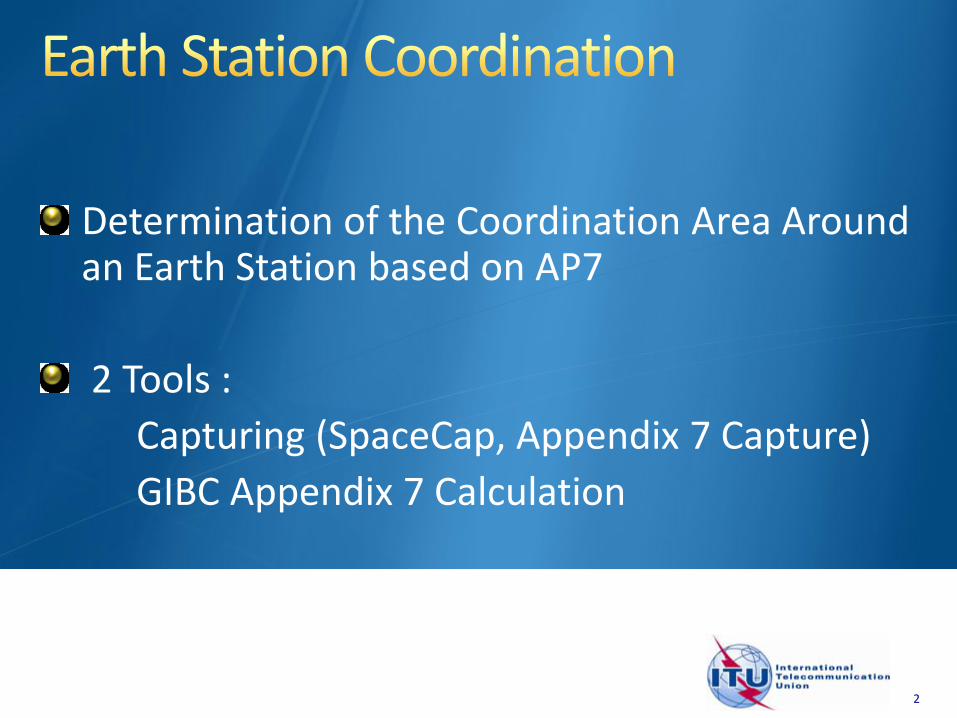
Determination of the Coordination Area Around an Earth Station based on AP7
2 Tools :
Capturing (SpaceCap, Appendix 7 Capture)
GIBC Appendix 7 Calculation
2
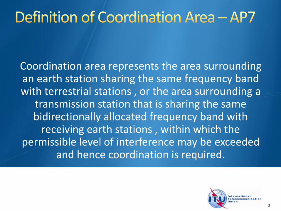
Coordination area represents the area surrounding an earth station sharing the same frequency band with terrestrial stations , or the area surrounding a
transmission station that is sharing the same bidirectionally allocated frequency band with
receiving earth stations , within which the permissible level of interference may be exceeded
and hence coordination is required.
3
0
45
90
135180
225
270
315
ALB
MKD
GRC
SUI
D
AUT
HNGF
E
ALG
TUN
LBY
EGY
ROU
BUL
TUR
I
YUG
SVN
HRV
BIH
SVK
MLT
Coordination Area-What does it mean?
Coordination Area-What does it mean?
Mode(1)
Mode(2)
Coordination contours with the greatest coordination distance
It represents a regulatory conceptbased on Worst Cases &
Conservative Assumptions.
However
i.e.
It’s not an exclusion zone.
means
More detailed calculations anddiscussions need to be performed.
44
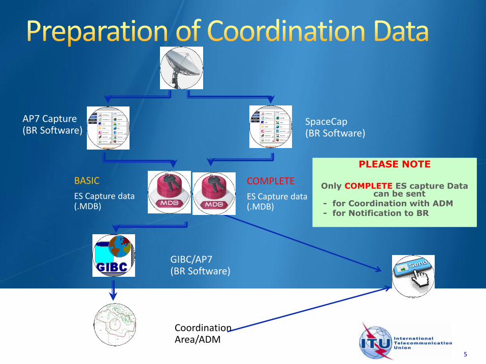
SpaceCap(BR Software)
COMPLETE
ES Capture data (.MDB)
5
BASIC
ES Capture data (.MDB)
AP7 Capture (BR Software)
PLEASE NOTE
Only COMPLETE ES capture Data can be sent
- for Coordination with ADM - for Notification to BR
PLEASE NOTE
Only COMPLETE ES capture Data can be sent
- for Coordination with ADM - for Notification to BR
GIBC/AP7(BR Software)
Coordination Area/ADM
6
GIBC Appendix 7 Calculation
o Software Installation
o Select input database
o Appendix 7 calculation
o Generate report document
o Include Auxiliary Contours
Proposed Exercises:
To generate Coordination Contours for FSS Transmitting and Receiving Earth Station in the 6/4 GHz band
To repeat the calculations to see the effect of the horizon elevation angles on the coordination contours
7
Install GIBC & Open
the application
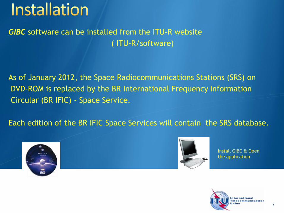
GIBC software can be installed from the ITU-R website
( ITU-R/software)
As of January 2012, the Space Radiocommunications Stations (SRS) on
DVD-ROM is replaced by the BR International Frequency Information
Circular (BR IFIC) - Space Service.
Each edition of the BR IFIC Space Services will contain the SRS database.
8
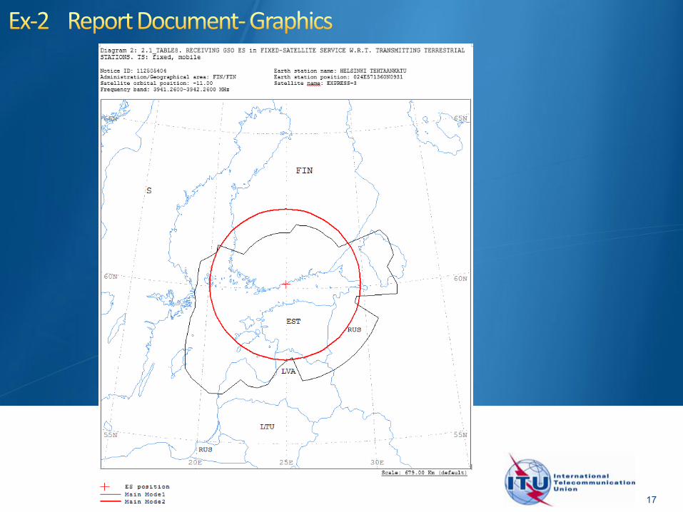
Generation of coordination contours:
FSS Transmitting and Receiving ES in the 6/4 GHz band
-Input example database (SNS format):
Tx&RxEarthStation@6&4GHz.mdb
-ES name: HELSINKI TEHTAANKATU
-ES Notice ID: Ex.1 112505405(with zero deg. horizon elevation angles)