WP-5530 Series Bezel Free All-in-One Modular Wall-Mount POS System User Manual Ver 1.0_2015/01/05 Before installing and operating the unit, please read this user manual thoroughly and retain for reference.
Transcript
WP-5530 Series Bezel Free All-in-One Modular Wall-Mount POS System
User Manual
Ver 1.0_2015/01/05
Before installing and operating the unit, please read this user manual thoroughly and retain for reference.
How to Use This Manual
This manual contains information to set up and use the WP-5530. In addition, instructions are included for added hardware, software, upgrades, and optional items. Chapter 1 An introduction to what you find in the box and an overview of product specifications,
appearance, and interface. Chapter 2 Detailed installation information for the base unit and upgrades, including the HDD, and
main memory. Chapter 3 Mounting procedures for optional devices, such as MSR, Fingerprint, I-Button, IC Card, WiFi,
Bluetooth, RFID, scanner, rear mount VFD, and swing arm kit. Chapter 4 IMB-151 and IMB-183 main board diagrams, locations of jumpers, and connectors. Chapter 5 Installation instructions for the Intel chipset driver, video driver, touch screen tools, audio,
LAN, RFID, Fingerprint, IC Card, system and OPOS drivers.
WARNING! Text set off in this manner indicates that failure to follow directions could result
in bodily harm or loss of life.
CAUTION: Text set off in this manner indicates that failure to follow directions could result in damage to equipment or loss of information.
NOTE: Text set off in this manner provides important supplemental information.
Federal Communications Commission (FCC) Notice
This equipment has been tested and found to comply with the limits for a Class A digital device, pursuant to Part 15 of the FCC Rules. These limits are designed to provide reasonable protection against harmful interference in a residential installation. This equipment generates, uses, and can radiate radio frequency energy and, if not installed and used in accordance with the instructions, may cause harmful interference to radio communications. However, there is no guarantee that interference will not occur in a particular installation. If this equipment does cause harmful interference to radio or television reception, which can be determined by turning the equipment off and on, the user is encouraged to try to correct the interference by one or more of the following measures:
Reorient or relocate the receiving antenna. Increase the separation between the equipment and the receiver.
Connect the equipment to an outlet on a circuit different from that to which the receiver is connected.
Consult the dealer or an experienced radio/TV technician for help.
NOTE: Shielded interconnect cables and shielded AC power cables must be employed
with this equipment to insure compliance with pertinent RF emission limits governing this device. Changes or modifications not expressly approved by the system’s manufacturer could void the user’s authority to operate the equipment.
This device complies with Part 15 of the FCC Rules. Operation is subject to the following two conditions:
1. This device may not cause harmful interference. 2. This device must accept any interference received, including interference that may cause undesired
1. Please read these safety instructions carefully. 2. Keep this User Manual for later reference. 3. Disconnect this equipment from the AC outlet before cleaning. Do not use liquid or spray detergent
for cleaning. Use only a moistened sheet or cloth. 4. For pluggable equipment, the socket outlet should be installed near the equipment and should be
easily accessible. 5. Avoid humidity and moisture. 6. Install equipment on a stable surface. 7. Do not leave this equipment running in an enclosed or non-air-circulated environment, nor store in
temperatures above 60°C. Such conditions may damage the equipment. 8. Ventilation openings on the unit are for air circulation and protect the equipment from overheating.
DO NOT COVER THE OPENINGS. 9. Check the voltage of the power source before connecting the equipment to the power outlet. 10. Place the power cord so that it will not be stepped on. Do not place anything over the power cord.
The power cord must be rated for the product and for the voltage and current marked on the product’s electrical ratings label. The voltage and current rating of the cord should be greater than the voltage and current rating marked on the product.
11. All cautions and warnings on the equipment should be noted. 12. If the equipment is not used for a long time, disconnect the equipment from the power outlet to
avoid damage. 13. Never allow any liquid into ventilation openings. This could cause fire or electrical shock. 14. Never open the equipment. For safety reasons, qualified service personnel should only open the
equipment. 15. If one of the following situations may arise, get the equipment checked by qualified service
personnel: a. The power cord or plug is damaged. b. Liquid has penetrated the equipment. c. The equipment has been exposed to moisture. d. The equipment does not work well or you cannot get it work according to the user manual. e. The equipment has been dropped and damaged. f. The equipment has obvious signs of damage.
WARNING! Not intended for outdoor use.
CAUTION: Danger of explosion if battery is incorrectly replaced. Replace only with same
type, and discard used batteries according to manufacturer's instructions.
Features ............................................................................................................................................. 1
2-in-1 Module (Magnetic Stripe Reader + IC Card Reader)
2-in-1 Module (Magnetic Stripe Reader + RFID)
VFD Customer Display: 9 mm height, 2 lines 20 characters each (rear mount type)
Wall Mount Swing Arm Kit
Stand Base:Counter Top Base, adjustable View Angle
Pole mount:Swing-arm mount, adjustable angle VESA
4
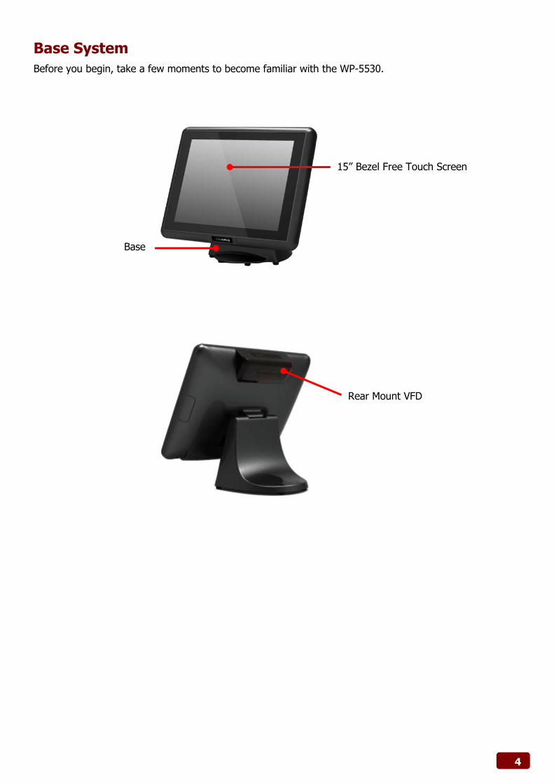
Base System
Before you begin, take a few moments to become familiar with the WP-5530.
15” Bezel Free Touch Screen
Base
Rear Mount VFD
5
Expandable Main Display
The four sides of the main display are specially designed for expandable functions and connect with one of the available internal USB ports or PS/2 for operation. Optimized for simple installation, these interfaces do not require any voltage setting adjustments.
RFID module (USB to COM interface) MSR (PS/2 interface) I-Button (PS/2 interface) Fingerprint (Fingerprint for USB interface) MSR+I-Button (PS/2 interface) MSR+Fingerprint (MSR for PS/2 interface, Fingerprint for USB interface) MSR+ IC Card Reader (MSR for PS/2 interface, IC Card Reader for USB interface)
MSR+ RFID (MSR for PS/2 interface, RFID for USB to COM interface)
NOTE: The Magnetic Stripe Reader module can only be installed to the right side of the front panel.
Optional: RFID I-Button Fingerprint MSR+ RFID MSR+I-Buttom MSR+Fingerprint MSR+ IC Card Reader
Single MSR
6
Convertible Pole-Type 2nd Display (optional)
The pole-type 2nd display is for use with the POS system to display purchase prices and change amounts to customers. It is also capable of displaying advertising messages and announcements. Five types of pole mount display choices are available: a 10.1” LCD monitor, a 12” LCD monitor and a 15” LCD monitor. The pole mount is located at the rear of the base and connects with the 2nd display port for operation. Whether installing a 10.1” LCD, 12” LCD or 15” LCD, there is no need to change any settings on the main board or I/O board.
Single Pole 2nd display choices: • 10.1” LCD • 12” LCD
• 15” LCD(shown)
7
Dimensions
(Unit: mm)
8
Connector Panel
The WP-5530's primary connector panel is located at the rear. For WP-5530-XX10
For WP-5530-XX20
Mic-In
12V POWERED USB
12V DC IN
2 x USB2.0
2 x USB3.0
Line-Out
HDMI
12V/24V Cash Drawer Switch
Cash Drawer
VGA COM1/2/3 (RI/5V/12V)
12V Output
LAN
DVI-I
mSATA
12V POWERED USB
VGA
2 x USB3.0
LAN Cash Drawer
12V/24V Cash Drawer Switch
COM1/2/3 (RI/5V/12V)
2 x USB2.0
12V DC IN
12V Output
Line-Out
Mic-In
HDMI
9
Chapter 2 Standard Hardware and Upgrades
Precautions
Before performing hardware changes, be sure to carefully read all of the applicable instructions, cautions, and warnings in this guide.
WARNING! To reduce the risk of personal injury from electrical shock, hot surfaces, or fire:
Disconnect the power cord from the wall outlet and allow the internal system components to cool before touching. Do not plug telecommunications or telephone connectors into the network interface controller receptacles. Do not disable the power cord grounding plug. The grounding plug is an important safety feature. Plug the power cord in a grounded (earthed) outlet that is easily accessible at all times.
CAUTION: Static electricity can damage the electrical components of the computer and/or
optional equipment. Before beginning these procedures, ensure that you are discharged of static electricity by briefly touching a grounded metal object. When the computer is plugged into an AC power source, voltage is always applied to the main board. You must disconnect the power cord from the power source before opening the unit to prevent damage to internal components.
10
Opening System Box
CAUTION: To prevent loss of work and damage to the system or drive:
If you are inserting or removing a drive, shut down the operating system properly, turn off the system, and unplug the power cord. Do not remove a drive while the system is on or in standby mode. Before handling a drive, ensure that you are discharged of static electricity. While handling a drive, avoid touching the connector.
1. Turn off the system power properly through the operating system, then turn off any external
devices.
2. Disconnect the power cord from the power outlet and disconnect any external devices.
WARNING! To avoid scratching the panel while dismantling the system, first place a piece of
cloth or cushion on your work surface.
3. For easier access place the main LCD display upside down, then pry VFD cover open with a flat
screw driver.
4. Detach the right side cover, left side cover and rear cover.
11
5. Unscrew six screws on the back cover of main LCD display as shown below to remove it.
6. Unscrew a screw on the HDD tray as shown below to remove it.
.
12
Clearing CMOS
The WP-5530's configuration (CMOS) may occasionally be corrupted. If it is, it will be necessary to clear the CMOS memory using jumper CLRCMOS1. Please refer to Chapter 4 for the exact CLRCMOS1 pin positions.
1. Turn off the system power properly through the operating system, then turn off any external devices.
2. Disconnect the power cord from the power outlet and disconnect any external devices.
CAUTION: Regardless of the power-on state, voltage is always present on the main board as
long as the system is plugged into an active AC outlet. The power cord must be disconnected from the power source before clearing the CMOS.
NOTE: All LEDs on the board should be OFF. Failure to ensure there is no power in the
system may damage the main board. You must disconnect the power cord to avoid damage to the internal components of the system.
3. Remove the system box and box cover.
4. Locate the JP1 jumper box on the main board IMB-151 and IMB-183. 5. Remove the jumper shunt from pins 2-3 and place over pins 1-2.
6. Wait 60 seconds to allow the CMOS to clear, then remove the jumper shunt and place it b ack in its
original position over pins 1-2.
7. Replace the box cover and system box into the system.
13
Memory Installation
The memory sockets on the main board can be populated with up to an industry-standard DIMM. The WP-5530 comes standard with one preinstalled DIMM. To achieve maximum memory performance, up to 8GB of memory for IMB-151 or up to 16GB of memory for IMB-183can be added.
CAUTION: You must disconnect the power cord and wait approximately 30 seconds for the
power to drain before adding or removing memory cards. Regardless of the power-on state, voltage is always supplied to the memory modules as long as the system is plugged into an active AC outlet. Adding or removing memory modules while voltage is present may cause irreparable damage to the memory modules or main board. If you see an LED light on the main board, voltage is still present.
The memory module sockets have gold-plated metal contacts. When upgrading the memory, it is important to use memory modules with gold-plated metal contacts to prevent corrosion and/or oxidation resulting from having incompatible metals in contact with each other.
Static electricity can damage the electronic components of the system or optional cards. Before beginning these procedures, ensure that you are discharged of static electricity by briefly touching a grounded metal object.
When handling a memory module, be careful not to touch any of the contacts. Doing so may damage the module.
1. Turn off the system power properly through the operating system, then turn off any external
devices.
2. Disconnect the power cord from the power outlet and disconnect any external devices.
CAUTION: Regardless of the power-on state, voltage is always present on the main board as
long as the system is plugged into an active AC outlet. You must disconnect the power cord to avoid damage to the internal components of the system.
WARNING! To reduce risk of personal injury from hot surfaces, allow the internal system
components to cool before touching.
3. For easier access place the main LCD display upside down, then pry VFD cover open with a flat screw driver.
14
4. Detach the right side cover, left side cover and rear cover.
5. Unscrew six screws on the back cover of main LCD display as shown below to remove it.
6. Unscrew a thumb screw on the HDD tray as shown below to remove it.
7. If an existing memory card or cards need to be replaced, pull the ends of both metal latches away
from the card to release it.
NOTE: A memory card can be installed in only one way. Match the notch on the card
with the tab in the memory socket.
15
8. Insert the new or replacement memory card into the socket, almost covering the gold contacts completely, then push the card down. If the card is fully inserted and properly seated, the metal latches will be in the closed position indicated.
9. Replace the RAM cover, then replace the system box.
10. Reconnect the power cord and any external devices, then turn on the system. The system should
automatically recognize the additional memory when powered up.
1 2
16
Removing and Replacing the SATA Hard Disk
NOTE: This system does not support Parallel ATA (PATA) hard drives.
Before removing the original hard drive, be sure to back up its data so that you can transfer the data to the replacement hard drive. Also, if you are replacing the primary hard drive, make sure you have a recovery disc set to restore the operating system, software drivers, and any software applications that were preinstalled on the system.
1. Turn off the system power properly through the operating system, then turn off any external
devices.
2. Disconnect the power cord from the power outlet and disconnect any external devices.
CAUTION: Regardless of the power-on state, voltage is always present on the main board as
long as the system is plugged into an active AC outlet. You must disconnect the power cord to avoid damage to the internal components of the system.
3. Detach the rear cover.
WARNING! To avoid scratching the panel during the dismantling process, first place a piece
of cloth or cushion underneath.
17
4. Unscrew a screw on the HDD tray as shown below to remove it.
5. Slide the HDD box off the main system.
6. Unscrew two screws on the HDD tray as shown below to remove it. Next, insert the replacement
hard disk into the HDD tray.
7. Slide the HDD tray back into the main system, ensuring that it is pressed all the way in and properly
seated.
8. Reattach a thumb screw that secure the HDD box.
9. Reattach the cover and screws.
10. Reconnect the power cord and any external devices, then turn on the system.
NOTE: The capacity of a sector is 4096 bytes for 320GB HDD of WD. They are only suitable for Win7 or OS developed later than Win7.
NOTE: The MSR module can only be installed to its designated position and socket; the
same with the wireless module. Their locations are not interchangeable.
1. Turn off the system power properly through the operating system, then turn off any external
devices.
2. Disconnect the power cord from the power outlet and disconnect any external devices.
CAUTION: Regardless of the power-on state, voltage is always present on the main board as
long as the system is plugged into an active AC outlet. You must disconnect the power cord to avoid damage to the internal components of the system.
3. Detach the right side cover.
4. Connect MSR cable into the socket.
5. Slide the MSR into the main LCD display. Reattach the two screws that secure the MSR to the main
system.
19
6. Reconnect the power cord and any external devices, then turn on the system.
NOTE: The MSR module configuration tool is in the included CD. If you need configure
MSR module, please execute the utility according to the procedure specified in Chapter 5.
20
Rear Mount VFD Installation
1. Turn off the system power properly through the operating system, then turn off any external
devices.
2. Disconnect the power cord from the power outlet and disconnect any external devices.
CAUTION: Regardless of the power-on state, voltage is always present on the main board as
long as the system is plugged into an active AC outlet. You must disconnect the power cord to avoid damage to the internal components of the system.
3. Pry VFD cover open with a flat screw driver.
4. Connect VFD cable or LCD cable into the KBTR connector of VFD KBTR board and then secure the
VFD module or LCD module.
5. Reconnect the power cord and any external devices, then turn on the system.
NOTE: The rear mount VFD module configuration utility is in the included CD. If you need
configure VFD module, please execute the utility according to the procedure specified in Chapter 5.
21
Cash Drawer Installation
NOTE: Before connecting cash drawer to the system, please make sure the driver
voltage and cable pin assignment of the cash drawer matches the definition of the system's cash drawer port.
Before installing the cash drawer to the system, please make sure the system driver has been installed.
1. Turn off the system power properly through the operating system, then turn off any external
devices.
2. Disconnect the power cord from the power outlet and disconnect any external devices.
CAUTION: Regardless of the power-on state, voltage is always present on the main board as
long as the system is plugged into an active AC outlet. You must disconnect the power cord to avoid damage to the internal components of the system.
3. Switch 12V/24V cash drawer switch according to your cash drawer’s specification, and then plug the
cash drawer cable into the cash drawer port.
4. Reconnect the power cord and any external devices, then turn on the system.
12V/24V Cash Drawer Switch
22
Chapter 4 Main Board Configuration
Jumper and Connector Locations of IMB-151
23
Connector Allocations
Connector Function
1 ATX Power Connector
2 2-pin UPS Module Power Input Connector
3 4-Pin CPU FAN Connector
4//5/6 PWR_COM6 / PWR_COM4 / PWR_COM3 Jumper
7 Internal COM Port Headers
8 Printer Port Header
9 PWR_COM1 Jumper
10 Digital Input / Output Pin Header
11 PWR_COM2 Jumper
12 Digital Input / Output Power Select
13 TPM Header
14 Chassis Intrusion Headers
15 SATA Power Output Connector
16 USB3.0 Connector
17 mSATA Select
18 PS2_KB_MS1
19 System Panel Header
20 CIR Header
21 Clear CMOS Header
22 USB2.0 Connectors
23 ATX/AT Mode Jumper
24 SPDIF Header
25 SATA2 Connectors
26 3-Pin Chassis FAN Connector
27 Backlight Power Connector
28 USB2.0 Connectors
29 3W Audio AMP Output Wafer
30 Backlight Power Selection
31 Panel Power Selection
32 Backlight Control Level
33 Audio Jack
34 Front Panel Audio Header
35 Audio Jack
36 Backlight Volume Control
37 HDMI Port
38 LVDS Panel Connector
39 USB3.0 Ports
40 VGA Port
41 VGA2
42 RJ45 LAN Port
43 USB2.0 Ports
44 DC Jack
24
Jumper Settings of IMB-151
To set jumper positions, place the jumper shunt over the pins designated in the table (SHORT) or remove
(NC) it from the jumper pins and store for future use. Default settings are indicated with a star symbol ().
ATX Power Connector (Input 9V-19V)
PIN No. Function
1-2 Short GND
3-4 Short DC Input
PWR_COM6/4/3 Jumper
PIN No. Function
1-2 Short 5V
2-3 Short 12V
PWR_COM1 Jumper
PIN No. Function
1-2 Short 5V
2-3 Short 12V
PWR_COM2 Jumper
PIN No. Function
1-2 Short 5V
2-3 Short 12V
3-4 Short 12V
4-5 Short 5VSB
Digital Input / Output Power Select
PIN No. Function
1-2 Short 12V
2-3 Short 5V
Chassis Intrusion Headers
PIN No. Function
Open Normal
Short Active case open
PWR_COM2
PWR_COM1
CI1
JGPIO_PWR11
PWR_COM6, PWR_COM4, PWR_COM3
ATX12V1
25
Chassis Intrusion Headers
PIN No. Function
Open Active case open
Short Normal
mSATA Select
PIN No. Function
1-2 Short SATA2_2 + mini-PCIe
2-3 Short mSATA, SATA2_2 no function
Clear CMOS Header
PIN No. Function
1-2 Short Normal
2-3 Short Clear CMOS
ATX/AT Mode Jumper
PIN No. Function
1-2 Short AT Mode
2-3 Short ATX Mode
Backlight Power Selection
PIN No. Function
1-2 Short LCD_BLT_VCC: +5V
2-3 Short LCD_BLT_VCC: +12V
4-5 Short LCD_BLT_VCC: DC_IN
Panel Power Selection
PIN No. Function
1-2 Short LVDD: +3V
2-3 Short LVDD: +5V
4-5 Short LVDD: 12V
PNL_PWR11
BKT_PWR1
ATX_AT1
CLRCOMS1
MSATA_SEL1
CI2
26
Backlight Control Level
PIN No. Function
1-2 Short +3V
2-3 Short +5V
BLT_PWM1
27
Jumper and Connector Locations of IMB-183
28
Connector Allocations
Connector Function
1 2-pin UPS Module Power Input Connector (UPS_IN1)
2 PS2 Keyboard/Mouse Header
3 4-pin ATX Power Input/Output Connector
4 USB2.0 Headers (USB4_5, USB8_9)
5 SATA3 Connectors (SATA3_1, SATA3_2)
6 Digital Input / Output Pin Header
7 SATA Power Output Connector (SATA_PWR1)
8 VCCM Power Selection
9 Digital Input / Output Power Selection
10/11/12/13 COM1, 2, 3, 4 Headers (COM1/2/3/4)
14 System Panel Header (PANEL1)
15 LVDS Panel Connector (LVDS1)
16 Panel Power Selection (PNL_PWR1)
17 BLT_CTL1
18 Backlight Power Selection (BKT_PWR1)
19 Backlight Control Level (BLT_PWM1)
20 Customer Solution Header (CS1)
21 ATX/AT Mode Selection
22 4-Pin CPU FAN Connector
23 DMIC Header
24 HDMI_SPDIF Header
25 Clear CMOS Header
26 3W Audio AMP Output Wafer
27 Audio Jack
28 Front Panel Audio Header
29 Audio Jack
30 TPM Header
31 USB2.0 Ports (USB23)
32 RJ45 LAN Port 1
33 Speaker Control
34 Top : eSATA Port (ESATA1), Bottom : HDMI Port (HDMI1)
35 VGA1
36 DVI Port (DVI1)
37 Chassis Intrusion Headers (CI1, CI2)
38 3-Pin Chassis FAN Connector (+12V)
39 USB3.0 Ports (USB01)
40 DC Jack1
29
Jumper Settings of IMB-183
To set jumper positions, place the jumper shunt over the pins designated in the table (SHORT) or remove
(NC) it from the jumper pins and store for future use. Default settings are indicated with a star symbol ().
VCCM Power Selection
PIN No. Function
Short 1.36V
Open Auto
Digital Input / Output Power Selection
PIN No. Function
1-2 Short 12V
2-3 Short 5V
Panel Power Selection
PIN No. Function
1-3 Short 3.3V
3-4 Short 12V
3-5 Short 5V
Backlight Power Selection
PIN No. Function
1-3 Short 5V
3-4 Short +VIN
3-5 Short 12V
Backlight Control Level
PIN No. Function
1-2 Short 3.3V
2-3 Short 5V
ATX/AT Mode Selection
PIN No. Function
1-2 Short AT mode
2-3 Short ATX mode
BKT_PWR1
PNL_PWR1
PWR_JP1
BLT_PWM1
JGPIO_PWR1
VCCM_PWR1
30
Clear CMOS Header
PIN No. Function
1-2 Short Normal
2-3 Short Clear CMOS
Chassis Intrusion Headers
PIN No. Function
Open Single
Short GND
Chassis Intrusion Headers
PIN No. Function
Open Single
Short GND
CI2
CI1
CLRCOMS1
31
Chapter 5 Software Setup
Pre-Installation Requirements
This system comes with a variety of drivers for different operating systems. A software CD is included in the package contents. The following section documents the procedures used to install the peripheral. 1. Insert sofeware CD into a system.
2. Run the setup.exe file on the CD.
3. Click 【Select Product】to select your POS model.
4. Click 【Select System】to select your operating system.
32
5. Select your POS model Number.
6. Select the peripheral driver that you want to install and then follow on-screen instructions to install
your driver or refer to following procedures specifying how every driver is to be installed.
3. Click Next on the Information screen. 4. Click Next to continue.
5. Select one of the options and click Finish.
34
Intel Graphics Driver Installation for IMB-151
1. Click Next on the Welcome screen. 2. Click Yes on the License Agreement screen.
3. Click Next on the readme File Information screen.
4. Click Install.
5. Click Install. 6. Click Next.
35
7. Select one of the options and click Finish.
36
Intel Graphics Driver Installation for IMB-183
1. Click Next on the Welcome screen. 2. Click Yes on the License Agreement screen.
3. Click Next on the readme File Information screen.
4. Click Next.
5. Select one of the options and click Finish.
37
Smart Connect Driver Installation For IMB-183
1. Click Next on the Welcome screen. 2. Click Next on the License Agreement screen.
3. Click OK. 4. Click Next.
5. Click Install to begin the installation. 6. Click the Finish to exit the Setup Wizard.
38
Management Engine Driver Installation For IMB-183
1. Click Next on the Welcome screen. 2. Click Yes on the License Agreement screen.
3. Click Next. 4. Select one of the options and click Finish..
39
TXE Driver Installation
1. Click Next on the Welcome screen. 2. Click Next on the License Agreement screen.
3. Click Next on the Information screen. 4. Click Install to install device software.
5. Click Finish.
40
Win8 BMI Driver Installation for IMB-151
1. Click Next on the Welcome screen. 2. Click Yes on the License Agreement screen.
3. Click Next to continue. 4. Select one option and click Finish.
41
ELO Touch Screen Driver Installation
1. Click OK on the Welcome screen. 2. Click Unzip on the WinZip Self-Extractor
screen.
3. Select language, click Next. 4. Click Next on welcome screen.
5. Click Yes on the License Agreement screen. 6. Select Auto-detect Elo Touchscreens, click
Next.
42
7. Select COM3, click Next. 8. Click Next to confirm COM port selection.
9. Click Finish.
43
Abon Touch Screen Driver Installation
1. Click Next on the Welcome screen. 2. Select the hid report mode, then click Next.
3. Check this option and click Next. 4. Check this option and click Next.
5. Select destination Location and then click Next.
6. Select start menu folde and then click Next.
44
7. Click Install to continue with the installlation. 8. Click Install to install this device software.
9. Click Yes to restart the computer now.
45
TPK Touch Screen Driver Installation
1. Click Next on the Welcome screen. 2. Select a destination folder, then click Next.
3. Check Finish.
46
Audio Driver Installation
1. Click Yes on the Welcome screen. 2. Select one of the options and click OK to finish
setup.
47
Ethernet Driver Installation For IMB-151
1. Click Next on the Welcome screen. 2. Click Install to begin the installation.
3. Click Finish.
48
Ethernet Driver Installation For IMB-183
1. Click Next on the Welcome screen. 2. Select one of the options and click Next on the
Agreement screen.
3. Click Next. 4. Click Install to begin installation.
5. Click Finish.
49
USB3.0 Driver Installation
1. Click Next on the Welcome screen. 2. Click Yes on the Agreement screen.
3. Click Next. 4. Click Next.
5. Select one of the options and Click Finish.
50
CIR Device Driver Installation for IMB-151
1. Choose Setup Language and click Next. 2. Click Next on the Welcome screen.
3. Click Finish.
51
Rear Mount VFD USB-to-Serial Driver Installation (optional)
The WP-5530 VFD port is a USB interface. The 9mm VFD uses a Serial interface, so in order to enable it, you must install the included USB-to-Serial interface driver.
1. First, plug in the VFD Module. 2. Enter the USB To COM Driver folder and then run utility program
PL2303_Prolific_driverInstaller_v130.
3. Click Next on the Welcome screen. 4. Wait as the driver is installed.
5. Click Finish.
52
RFID Driver Installation (optional)
1. First, plug in the RFID Module. 2. Driver Path.
X:\Peripheral\RFID\Windows 7_32Bit XP driver X:\Peripheral\RFID\Windows7_64Bit Driver
3. Device Manager (Install USB Serial converter) 4. Update device software.
3. For PS2 interface: Run the MSRfgSetup_V1_4R7_PSW00025.exe.
For USB interface: Enter the Software folder and then run the HISD_MSR_PSW00003.exe.
4. Follow on-screen instructions to install your MSR driver.
NOTE: MSR with PS2 interface don’t support 64 Bits OS.
56
Fingerprint Reader Driver Installation (optional)
1. Plug in the 2-in-1 Fingerprint Reader and MSR module. 2. Enter the SDK folder and then run the setup.exe.
3. Click Next on the Welcome screen. 4. Click Next on the License Agreement screen.
5. Click Next to accept the destination folder. 6. Click Next to begin installation.
7. To proceed with the installation, click Next. 8. Click Install to begin the installation.
57
9. Wait as the driver is installed. 10. Click Finish.
11. Click Yes to restart the system (required).
58
IC Card Reader Driver Installation (optional)
1. Plug in the 3-in-1 MSR/I-Button/IC Card Reader module. 2. Enter the EZ100PU Driver folder. 3. Select your POS operating system and then run the setup.exe.
4. Select language, click OK. 5. Click Next on the Welcome screen.
6. Click Install to begin the installation. 7. Wait as the driver is installed.
8. Click OK on the Note screen. 9. Click Finish.
59
System Driver Installation
1. Click Next on the Welcome screen. 2. Click Install on the Ready to Install screen.
3. Click Finish on the Completing installation screen. A system restart is required to complete the installation.
60
OPOS CCO Driver Installation
The OPOS driver for the WP-5530 supports the MSR, I-Button (KeyLock), RFID, VFD (Line-Display) and Scanner. Before installing the OPOS driver, please make sure the System Driver has been installed.
1. Click Next on the Welcome screen. 2. Click Next on the ReadMe screen.
3. Select the Destination Location and click Next. 4. Click Yes to backup the CCO files and select
backup file destination directory, then click Next.
5. Select Common Control Objects and OPOS Include Files, then Click Next.
6. Click Next on the Start Installation screen.
61
7. Click Finish on the Installation Complete screen.
62
OPOS Driver Installation
1. Click Next on the Welcome screen. 2. Click Install on the Setup screen.
3. Click Finish on the Completing installation screen.
63
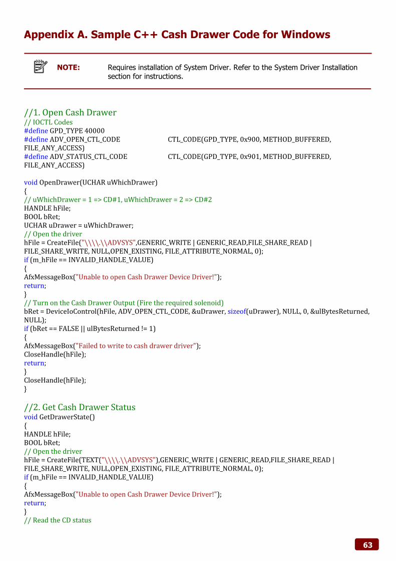
Appendix A. Sample C++ Cash Drawer Code for Windows
NOTE: Requires installation of System Driver. Refer to the System Driver Installation
section for instructions.
//1. Open Cash Drawer // IOCTL Codes #define GPD_TYPE 40000 #define ADV_OPEN_CTL_CODE CTL_CODE(GPD_TYPE, 0x900, METHOD_BUFFERED, FILE_ANY_ACCESS) #define ADV_STATUS_CTL_CODE CTL_CODE(GPD_TYPE, 0x901, METHOD_BUFFERED, FILE_ANY_ACCESS) void OpenDrawer(UCHAR uWhichDrawer) { // uWhichDrawer = 1 => CD#1, uWhichDrawer = 2 => CD#2 HANDLE hFile; BOOL bRet; UCHAR uDrawer = uWhichDrawer; // Open the driver hFile = CreateFile("\\\\.\\ADVSYS",GENERIC_WRITE | GENERIC_READ,FILE_SHARE_READ | FILE_SHARE_WRITE, NULL,OPEN_EXISTING, FILE_ATTRIBUTE_NORMAL, 0); if (m_hFile == INVALID_HANDLE_VALUE) { AfxMessageBox("Unable to open Cash Drawer Device Driver!"); return; } // Turn on the Cash Drawer Output (Fire the required solenoid) bRet = DeviceIoControl(hFile, ADV_OPEN_CTL_CODE, &uDrawer, sizeof(uDrawer), NULL, 0, &ulBytesReturned, NULL); if (bRet == FALSE || ulBytesReturned != 1) { AfxMessageBox("Failed to write to cash drawer driver"); CloseHandle(hFile); return; } CloseHandle(hFile); }
//2. Get Cash Drawer Status void GetDrawerState() { HANDLE hFile; BOOL bRet; // Open the driver hFile = CreateFile(TEXT("\\\\.\\ADVSYS"),GENERIC_WRITE | GENERIC_READ,FILE_SHARE_READ | FILE_SHARE_WRITE, NULL,OPEN_EXISTING, FILE_ATTRIBUTE_NORMAL, 0); if (m_hFile == INVALID_HANDLE_VALUE) { AfxMessageBox("Unable to open Cash Drawer Device Driver!"); return; } // Read the CD status
Appendix C. Sample VB6.0 Cash Drawer Code for Windows
NOTE: Requires installation of System Driver. Refer to the System Driver Installation
section for instructions.
Option Explicit On Private Declare Function CreateFile Lib "kernel32" Alias "CreateFileA" (ByVal lpFileName As String, ByVal dwDesiredAccess As Long, ByVal dwShareMode As Long, ByVal lpSecurityAttributes As SECURITY_ATTRIBUTES, ByVal dwCreationDisposition As Long, ByVal dwFlagsAndAttributes As Long, ByVal hTemplateFile As Long) As Long Private Declare Function DeviceIoControl Lib "kernel32" (ByVal hDevice As Long, ByVal dwIoControlCode As Long, ByVal lpInBuffer As Any, ByVal nInBufferSize As Long, ByVal lpOutBuffer As Any, ByVal nOutBufferSize As Long, ByVal lpBytesReturned As Long, ByVal lpOverlapped As OVERLAPPED) As Long Private Declare Function CloseHandle Lib "kernel32.dll" (ByVal hObject As Long) As Long 'CreateFile Custom Variables Private Type SECURITY_ATTRIBUTES nLength As Long lpSecurityDescriptor As Long bInheritHandle As Long End Type 'DeviceIoControl Custom Variables Private Type OVERLAPPED Internal As Long InternalHigh As Long offset As Long OffsetHigh As Long hEvent As Long End Type Dim DeviceHandle As Integer Dim SA As SECURITY_ATTRIBUTES Dim SA1 As OVERLAPPED Dim ADV_OPEN_CTL_CODE As Long Dim ADV_STATUS_CTL_CODE As Long Private Const GENERIC_READ As Long = &H80000000 Private Const GENERIC_WRITE As Long = &H40000000 Private Const FILE_SHARE_READ As Long = &H1 Private Const FILE_SHARE_WRITE As Long = &H2 Private Const OPEN_EXISTING As Long = &H3 Private Const FILE_ATTRIBUTE_NORMAL As Long = &H80 Private Const INVALID_HANDLE_VALUE As Long = &HFFFFFFFF Private Const METHOD_BUFFERED As Long = 0, FILE_ANY_ACCESS As Long = 0 Private Function CTL_CODE(ByVal lngDevFileSys As Long, ByVal lngFunction As Long, ByVal lngMethod As Long, ByVal lngAccess As Long) As Long CTL_CODE = (lngDevFileSys) Or (lngAccess * (2 ^ 14)) Or (lngFunction * (2 ^ 2)) Or lngMethod End Function
68
Private Sub Form_Load() '-1673527296 Come from c code (40000 <<16) ADV_OPEN_CTL_CODE = CTL_CODE(-1673527296, &H900, METHOD_BUFFERED, FILE_ANY_ACCESS) ADV_STATUS_CTL_CODE = CTL_CODE(-1673527296, &H901, METHOD_BUFFERED, FILE_ANY_ACCESS) DeviceHandle = CreateFile("\\.\ADVSYS", GENERIC_READ Or GENERIC_WRITE, FILE_SHARE_READ Or FILE_SHARE_WRITE, SA, OPEN_EXISTING, FILE_ATTRIBUTE_NORMAL, 0) If DeviceHandle = INVALID_HANDLE_VALUE Then 'Failed to Open Cash Drawer Driver MsgBox("Error opening ADVSYS.sys. Error = " & Err.LastDllError) End If End Sub Private Sub Command1_Click() Dim iBytesRtn As Long Dim iRet As Integer, iDrawer As Integer ' Open Drawer #1 iDrawer = &H1 iRet = DeviceIoControl(DeviceHandle, ADV_OPEN_CTL_CODE, iDrawer, 4, 0, 0, iBytesRtn, SA1) If (iRet = 0 Or iBytesRtn <> 1) Then MsgBox("Error opening ADVSYS.sys. Error = " & Err.LastDllError) End If End Sub Private Sub Command2_Click() Dim iBytesRtn As Long Dim iRet As Integer, iDrawer As Integer ' Open Drawer #2 iDrawer = &H2 iRet = DeviceIoControl(DeviceHandle, ADV_OPEN_CTL_CODE, iDrawer, 4, 0, 0, iBytesRtn, SA1) If (iRet = 0 Or iBytesRtn <> 1) Then MsgBox("Error opening ADVSYS.sys. Error = " & Err.LastDllError) End If End Sub Private Sub Timer1_Timer() Dim iBytesRtn As Long Dim iRet As Integer, iStatus As Integer ' Get Drawer Status iRet = DeviceIoControl(DeviceHandle, ADV_STATUS_CTL_CODE, 0, 0, iStatus, 4, iBytesRtn, SA1) If (iRet = 0 Or iBytesRtn <> 1) Then Timer1.Enabled = False MsgBox("Error opening ADVSYS.sys. Error = " & Err.LastDllError) End If If (iStatus = 0) Then Label1.Caption = "Cash Drawer(s) Closed" Else Label1.Caption = "Cash Drawer(s) Open" End If End Sub
69
Appendix D. Watch Dog C++ Sample Code for IMB-183
//1. Open Cash Drawer // IOCTL Codes #define GPD_TYPE 40000 #define ADV_WDOGSec_CTL_CODE CTL_CODE(ADVPORT_TYPE, 0x902, METHOD_BUFFERED, FILE_ANY_ACCESS) #define ADV_WDOGMin_CTL_CODE CTL_CODE(ADVPORT_TYPE, 0x903, METHOD_BUFFERED, FILE_ANY_ACCESS) #define ADV_COLSE_CTL_CODE CTL_CODE(ADVPORT_TYPE, 0x904, METHOD_BUFFERED, FILE_ANY_ACCESS) 2. //Open Second Mode void OpenWDOG(UCHAR uWhichdog) { // uWhichdog Number of seconds 1 to 255 HANDLE hFile; BOOL bRet; UCHAR uTime = uWhichdog; // Open the driver hFile = CreateFile("\\\\.\\ADVSYS",GENERIC_WRITE | GENERIC_READ,FILE_SHARE_READ | FILE_SHARE_WRITE, NULL,OPEN_EXISTING, FILE_ATTRIBUTE_NORMAL, 0); if (m_hFile == INVALID_HANDLE_VALUE) { AfxMessageBox("Unable to open Watch Dog Driver!"); return; } // Watch Dog timer setting to Seconds (Seconds & minutes, a second election) bRet = DeviceIoControl(hFile, ADV_WDOGSec_CTL_CODE, &uTime, sizeof(uTime), NULL, 0, &ulBytesReturned, NULL); if (bRet == FALSE || ulBytesReturned != 1) { AfxMessageBox("Failed to write to Watch Dog driver"); CloseHandle(hFile); return; } // Watch Dog timer setting to Minutes (Seconds & minutes, a second election) bRet = DeviceIoControl(hFile, ADV_WDOGMin_CTL_CODE, &uTime, sizeof(uTime), NULL, 0, &ulBytesReturned, NULL); if (bRet == FALSE || ulBytesReturned != 1) { AfxMessageBox("Failed to write to Watch Dog driver"); CloseHandle(hFile); return; } CloseHandle(hFile); } 3. //Close Watch Dog void CloseWDOG() { HANDLE hFile; BOOL bRet; UCHAR uTime = 0; // Number of 0 // Open the driver hFile = CreateFile("\\\\.\\ADVSYS",GENERIC_WRITE | GENERIC_READ,FILE_SHARE_READ |
70
FILE_SHARE_WRITE, NULL,OPEN_EXISTING, FILE_ATTRIBUTE_NORMAL, 0); if (m_hFile == INVALID_HANDLE_VALUE) { AfxMessageBox("Unable to open Watch Dog Driver!"); return; } // Close Watch Dog bRet = DeviceIoControl(hFile, ADV_COLSE_CTL_CODE CTL_CODE, &uTime, sizeof(uTime), NULL, 0, &ulBytesReturned, NULL); if (bRet == FALSE || ulBytesReturned != 1) { AfxMessageBox("Failed to write to Watch Dog driver"); CloseHandle(hFile); return; } CloseHandle(hFile); }
71
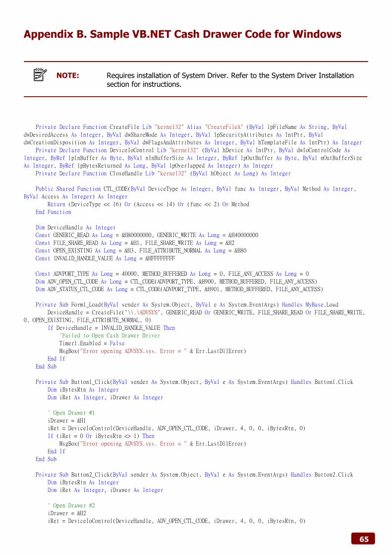
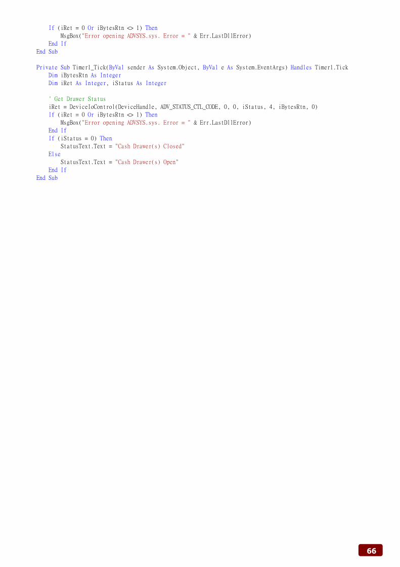
Appendix E. Watch Dog VB.NET Sample Code for IMB-183
Public Class Form1 Private Declare Function CreateFile Lib "kernel32" Alias "CreateFileA" (ByVal lpFileName As String, ByVal dwDesiredAccess As Integer, ByVal dwShareMode As Integer, ByVal lpSecurityAttributes As IntPtr, ByVal dwCreationDisposition As Integer, ByVal dwFlagsAndAttributes As Integer, ByVal hTemplateFile As IntPtr) As Integer Private Declare Function DeviceIoControl Lib "kernel32" (ByVal hDevice As IntPtr, ByVal dwIoControlCode As Integer, ByRef lpInBuffer As Byte, ByVal nInBufferSize As Integer, ByRef lpOutBuffer As Byte, ByVal nOutBufferSize As Integer, ByRef lpBytesReturned As Long, ByVal lpOverlapped As Integer) As Integer Private Declare Function CloseHandle Lib "kernel32" (ByVal hObject As Long) As Integer Public Shared Function CTL_CODE(ByVal DeviceType As Integer, ByVal func As Integer, ByVal Method As Integer, ByVal Access As Integer) As Integer Return (DeviceType << 16) Or (Access << 14) Or (func << 2) Or Method End Function Dim DeviceHandle As Integer Const GENERIC_READ As Long = &H80000000, GENERIC_WRITE As Long = &H40000000 Const FILE_SHARE_READ As Long = &H1, FILE_SHARE_WRITE As Long = &H2 Const OPEN_EXISTING As Long = &H3, FILE_ATTRIBUTE_NORMAL As Long = &H80 Const INVALID_HANDLE_VALUE As Long = &HFFFFFFFF Const ADVPORT_TYPE As Long = 40000, METHOD_BUFFERED As Long = 0, FILE_ANY_ACCESS As Long = 0 Dim ADV_WDOGSec_CTL_CODE As Long = CTL_CODE(ADVPORT_TYPE, &H902, METHOD_BUFFERED, FILE_ANY_ACCESS) Dim ADV_WDOGMin_CTL_CODE As Long = CTL_CODE(ADVPORT_TYPE, &H903, METHOD_BUFFERED, FILE_ANY_ACCESS) Dim ADV_COLSE_CTL_CODE As Long = CTL_CODE(ADVPORT_TYPE, &H904, METHOD_BUFFERED, FILE_ANY_ACCESS) Dim iBytesRtn As Integer Dim iRet As Integer, iDrawer As Integer Private Sub Form1_Load(ByVal sender As System.Object, ByVal e As System.EventArgs) Handles MyBase.Load DeviceHandle = CreateFile("\\.\WDOG", GENERIC_READ Or GENERIC_WRITE, FILE_SHARE_READ Or FILE_SHARE_WRITE, 0, OPEN_EXISTING, FILE_ATTRIBUTE_NORMAL, 0) If DeviceHandle = INVALID_HANDLE_VALUE Then 'Failed to Open Cash Drawer Driver MsgBox("Error opening ADVSYS.sys. Error = " & Err.LastDllError) End If End Sub Private Sub Button1_Click(ByVal sender As System.Object, ByVal e As System.EventArgs) Handles Button1.Click Label2.Text = 0 'Open Second Mode iDrawer = Val(TextBox1.Text) 'Number of seconds 1 to 255 iRet = DeviceIoControl(DeviceHandle, ADV_WDOGSec_CTL_CODE, iDrawer, 4, 0, 0, iBytesRtn, 0) If (iRet = 0 Or iBytesRtn <> 1) Then MsgBox("Error opening ADVSYS.sys. Error = " & Err.LastDllError) End If Timer1.Enabled = True End Sub Private Sub Button2_Click(ByVal sender As System.Object, ByVal e As System.EventArgs) Handles Button2.Click Label2.Text = 0 'Open Minute Mode iDrawer = Val(TextBox1.Text) 'Number of seconds 1 to 255 iRet = DeviceIoControl(DeviceHandle, ADV_WDOGMin_CTL_CODE, iDrawer, 4, 0, 0, iBytesRtn, 0) If (iRet = 0 Or iBytesRtn <> 1) Then MsgBox("Error opening ADVSYS.sys. Error = " & Err.LastDllError) End If Timer1.Enabled = True
72
End Sub Private Sub Button3_Click(ByVal sender As System.Object, ByVal e As System.EventArgs) Handles Button3.Click 'Close Watch Dog iDrawer = &H0 iRet = DeviceIoControl(DeviceHandle, ADV_COLSE_CTL_CODE, iDrawer, 4, 0, 0, iBytesRtn, 0) If (iRet = 0 Or iBytesRtn <> 1) Then MsgBox("Error opening ADVSYS.sys. Error = " & Err.LastDllError) End If Timer1.Enabled = False TextBox1.Text = 0 Label2.Text = 0 End Sub Private Sub Timer1_Tick(ByVal sender As System.Object, ByVal e As System.EventArgs) Handles Timer1.Tick Label2.Text = Val(Label2.Text) + 1 End Sub End Class
73
Appendix F. Watch Dog VB6 Sample Code for IMB-183
Option Explicit On Private Declare Function CreateFile Lib "kernel32" Alias "CreateFileA" (ByVal lpFileName As String, ByVal dwDesiredAccess As Long, ByVal dwShareMode As Long, ByVal lpSecurityAttributes As SECURITY_ATTRIBUTES, ByVal dwCreationDisposition As Long, ByVal dwFlagsAndAttributes As Long, ByVal hTemplateFile As Long) As Long Private Declare Function DeviceIoControl Lib "kernel32" (ByVal hDevice As Long, ByVal dwIoControlCode As Long, ByVal lpInBuffer As Any, ByVal nInBufferSize As Long, ByVal lpOutBuffer As Any, ByVal nOutBufferSize As Long, ByVal lpBytesReturned As Long, ByVal lpOverlapped As OVERLAPPED) As Long Private Declare Function CloseHandle Lib "kernel32.dll" (ByVal hObject As Long) As Long 'CreateFile Custom Variables Private Type SECURITY_ATTRIBUTES nLength As Long lpSecurityDescriptor As Long bInheritHandle As Long End Type 'DeviceIoControl Custom Variables Private Type OVERLAPPED Internal As Long InternalHigh As Long offset As Long OffsetHigh As Long hEvent As Long End Type Dim DeviceHandle As Integer Dim SA As SECURITY_ATTRIBUTES Dim SA1 As OVERLAPPED Dim ADV_WDOGSec_CTL_CODE As Long Dim ADV_WDOGMin_CTL_CODE As Long Dim ADV_COLSE_CTL_CODE As Long Dim iBytesRtn As Long Dim iRet As Integer, iDrawer As Integer Private Const GENERIC_READ As Long = &H80000000 Private Const GENERIC_WRITE As Long = &H40000000 Private Const FILE_SHARE_READ As Long = &H1 Private Const FILE_SHARE_WRITE As Long = &H2 Private Const OPEN_EXISTING As Long = &H3 Private Const FILE_ATTRIBUTE_NORMAL As Long = &H80 Private Const INVALID_HANDLE_VALUE As Long = &HFFFFFFFF Private Const METHOD_BUFFERED As Long = 0, FILE_ANY_ACCESS As Long = 0 Private Function CTL_CODE(ByVal lngDevFileSys As Long, ByVal lngFunction As Long, ByVal lngMethod As Long, ByVal lngAccess As Long) As Long CTL_CODE = (lngDevFileSys) Or (lngAccess * (2 ^ 14)) Or (lngFunction * (2 ^ 2)) Or lngMethod End Function Private Sub Form_Load() '-1673527296 Come from c code (40000 <<16) ADV_WDOGSec_CTL_CODE = CTL_CODE(-1673527296, &H902, METHOD_BUFFERED, FILE_ANY_ACCESS) ADV_WDOGMin_CTL_CODE = CTL_CODE(-1673527296, &H903, METHOD_BUFFERED, FILE_ANY_ACCESS) ADV_COLSE_CTL_CODE = CTL_CODE(-1673527296, &H904, METHOD_BUFFERED, FILE_ANY_ACCESS) DeviceHandle = CreateFile("\\.\WDOG", GENERIC_READ Or GENERIC_WRITE, FILE_SHARE_READ Or FILE_SHARE_WRITE, SA, OPEN_EXISTING, FILE_ATTRIBUTE_NORMAL, 0) If DeviceHandle = INVALID_HANDLE_VALUE Then 'Failed to Open Cash Drawer Driver MsgBox("Error opening WDOG.sys. Error = " & Err.LastDllError) End If End Sub Private Sub Command1_Click() 'Button1 Label2.Caption = 0
74
'Open Second Mode iDrawer = Val(Text1.Text) 'Number of seconds 1 to 255 iRet = DeviceIoControl(DeviceHandle, ADV_WDOGSec_CTL_CODE, iDrawer, 4, 0, 0, iBytesRtn, SA1) If (iRet = 0 Or iBytesRtn <> 1) Then MsgBox("Error opening WDOG.sys. Error = " & Err.LastDllError) End If Timer1.Enabled = True End Sub Private Sub Command2_Click() 'Button2 Label2.Caption = 0 'Open Minute Mode iDrawer = Val(Text1.Text) 'Number of minutes 1 to 255 iRet = DeviceIoControl(DeviceHandle, ADV_WDOGMin_CTL_CODE, iDrawer, 4, 0, 0, iBytesRtn, SA1) If (iRet = 0 Or iBytesRtn <> 1) Then MsgBox("Error opening WDOG.sys. Error = " & Err.LastDllError) End If Timer1.Enabled = True End Sub Private Sub Command3_Click() 'Button3 'Close Watch Dog Text1.Text = 0 iDrawer = 0 iRet = DeviceIoControl(DeviceHandle, ADV_COLSE_CTL_CODE, iDrawer, 4, 0, 0, iBytesRtn, SA1) If (iRet = 0 Or iBytesRtn <> 1) Then MsgBox("Error opening WDOG.sys. Error = " & Err.LastDllError) End If Label2.Caption = 0 Timer1.Enabled = False End Sub Private Sub Timer1_Timer() Label2.Caption = Val(Label2.Caption) + 1 End Sub