The Pixel Controller Electron is designed to be the smallest, most versatile pixel controller available with the ability to control most any type of addressable pixel. It features a 3-axis accelerometer for feedback and is optimized for flow toys, wearable applications, and dynamic lighting applications. Using the free software NLED Aurora Control, the user can create endlessly customizable color sequences and patterns, as well as P.O.V(Point of Vision) graphics. With 16 megabytes of onboard flash memory, accessible over micro USB and through addon WiFi or Bluetooth modules. No need for SD cards, readers, or extra equipment, all that is required is a micro USB cable same as your smart phone uses. It is compatible with voltages as low as 2 volts, no need for boost circuits or extra batteries. In addition to the the powerful stand-alone features, it also is capable of direct control of the outputs through TTL serial from external devices such as X-Bees, Arduinos, and FTDI adapters. It also supports DMX-512 reception, with a special stand-alone sequence control method, which allows sequences to be triggered and controlled. Designed and manufactured in the U.S.A. to high standards, this controller offers a 3 year warranty and satisfaction guarantee.
Features:
*See Mass Control firmware and Packet Cloning**Screw-down terminal, right angle polarized header, unpopulated(bare) or JST-SM harness, see pg. 10
- Up to 512 Channels in Stand-Alone Usage and Data Reception.(Future updates will allow 1024)- Supports Multiple Pixel Chipsets - WS2801, WS2811, WS2812, WS2812B, LPD8806, LPD6803, LPD1886, TM1803, APA102, APA104, APA106, P9823, SK6812, and more.- USB Connectivity - Control thousands of pixels over USB- Customizable Stand-Alone Color Sequences using NLED Aurora Control Software.- Utilizes a 3-Axis Accelerometerm great for flow toys such as poi, staves, or hoops.- Supports P.O.V., Point of Vision sequences. Display images in the air.- Incredibly small form factor, 0.6" x 1.25" x 0.2" thick. Fits in 5/8" ID tube.- Onboard 16 megabyte memory, NO SD card required. Accessible via native USB or addon WiFi/Bluetooth- Supports DMX-512 with add-on transciever. With DMX stand-alone sequence control.- Supports DMX-512 Master transmission via expansion header or Output header instead of pixel protocol.- Supports TTL Serial at all baud rates, control from an Arduino or other serial devices.- Supports WiFi via an ESP8266, XBee, or similar products. Or Bluetooth via modules.- Low voltage, 3.3v to 12 volt support. Power it and LED pixels from a single lithium ion battery.- Bootloader Support, easily apply future upgrades and bug fixes, using only a USB cable.- Designed and Manufactured in The United States. Includes 3 Year Warranty and Lifetime Support.
Need Another Pixel Chipset Supported? Contact [email protected] to request it.
Supported Pixel Chipsets
Many of the most popular pixel chipsets are compatible with this controller. Each chipset has an unique control protocol, hardware specifications, voltage requirements, and color order. You must select the correct chipset and color order for your pixels. The options can only be changed through the software or USB commands. See pg. xx for details on the configuration settings.
The pixels can be directly controlled over USB using USB Live Control. The standard Aurora compatible firmware supports 170 pixels for self-clocking(3 wire) types, and 550 pixels for the sychronous(4 wire) type of pixels. In addition, there is are separate firmware versions(Mass Control types) available that allows the controller to control up to 2048 pixels in a single strand over USB. But does not offer many stand-alone control options.
The Aurora firmware supports Pixel Packet Cloning, which allows pixel strands longer than than the maximum of 512 channels of LEDs to be controlled over stand-alone. It is described later in this datasheet and in the NLED Aurora Control Manual. Example: User wants to control 680 pixels, setup sequences for 170 pixels with a packet clone value of 4. Now pixel 1, 171, 341, 511 will all act the same, as will pixel 2, 172, 342, 512, as will pixel 170, 340, 510, 680.
Fig. 2a
WS2811, WS2812/B
SK6812
TM1814
APA102 / SK9822
WS2801 / WS2803
APA104 / APA106 / P9823
LPD6803
LPD8806
LPD1886
8-bit
8-bit
8-bit
8-bit
8-bit
8-bit
5-bit
7-bit
12-bit
800Khz
800Khz
800Khz
20Mhz
2.66MHz
800Khz
10MHz
8MHz
16Mhz
Name Bits* Data Speed Frequency
400Hz
400Hz
400Hz
20Khz
2.5kHz
400Hz
N/A
4kHz
400Hz
THIS LIST IS NOT COMPLETE, PLEASE SEE WEBSITE IF CHIPSET IS NOT LISTED
Visit www.NLEDshop.com/pixelchipsets for the up to date list of supported chipsets.
Color PWM
*Same as PWM Resolution, current firmware will down-convert higher resolutions to 8-bit**Aurora firmware supports 170(3-wire) or 550(4-wire), and the listed number with the Mass Control firmware version.
ControlMethod
Self Clock
Self Clock
Self Clock
Mod. SPI
Stnd. SPI
Self Clock
Mod. SPI
Mod. SPI
Self Clock
Wires
3
3
3
4
4
3
4
4
3
Color
RGB
RGBW
RGB
RGB
RGB
RGB
RGB
RGB
RGB
Max USBPixels**
1024
768
1024
2048
2048
1024
2048
2048
1024
Pg. 2
A new feature for version 2 is the ability to utilize the Pixel Output for DMX-512 master transmission. That can be set under the “Select The Pixel Chipset” configuration, then rather than sending out data for a pixel to receive, it will send out(over the DAT or CLK header) a DMX-512 universe at TTL levels. That signal can not be directly connected to DMX receivers(it can but not reliably) and would have to be converted to RS-485, or directed into a compatible controller(such as the Pixel Controller Mini or Micro)
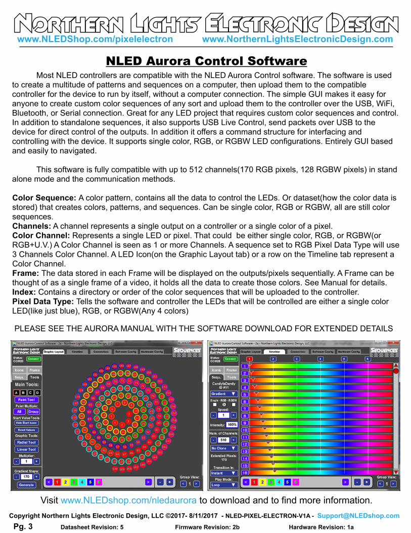
Visit www.NLEDshop.com/nledaurora to download and to find more information.
Color Sequence: A color pattern, contains all the data to control the LEDs. Or dataset(how the color data is stored) that creates colors, patterns, and sequences. Can be single color, RGB or RGBW, all are still color sequences.Channels: A channel represents a single output on a controller or a single color of a pixel.Color Channel: Represents a single LED or pixel. That could be either single color, RGB, or RGBW(or RGB+U.V.) A Color Channel is seen as 1 or more Channels. A sequence set to RGB Pixel Data Type will use 3 Channels Color Channel. A LED Icon(on the Graphic Layout tab) or a row on the Timeline tab represent a Color Channel.Frame: The data stored in each Frame will be displayed on the outputs/pixels sequentially. A Frame can be thought of as a single frame of a video, it holds all the data to create those colors. See Manual for details.Index: Contains a directory or order of the color sequences that will be uploaded to the controller.Pixel Data Type: Tells the software and controller the LEDs that will be controlled are either a single color LED(like just blue), RGB, or RGBW(Any 4 colors)
PLEASE SEE THE AURORA MANUAL WITH THE SOFTWARE DOWNLOAD FOR EXTENDED DETAILS
Pg. 3
Most NLED controllers are compatible with the NLED Aurora Control software. The software is used to create a multitude of patterns and sequences on a computer, then upload them to the compatible controller for the device to run by itself, without a computer connection. The simple GUI makes it easy for anyone to create custom color sequences of any sort and upload them to the controller over the USB, WiFi, Bluetooth, or Serial connection. Great for any LED project that requires custom color sequences and control. In addition to standalone sequences, it also supports USB Live Control, send packets over USB to the device for direct control of the outputs. In addition it offers a command structure for interfacing and controlling with the device. It supports single color, RGB, or RGBW LED configurations. Entirely GUI based and easily to navigated. This software is fully compatible with up to 512 channels(170 RGB pixels, 128 RGBW pixels) in stand alone mode and the communication methods.
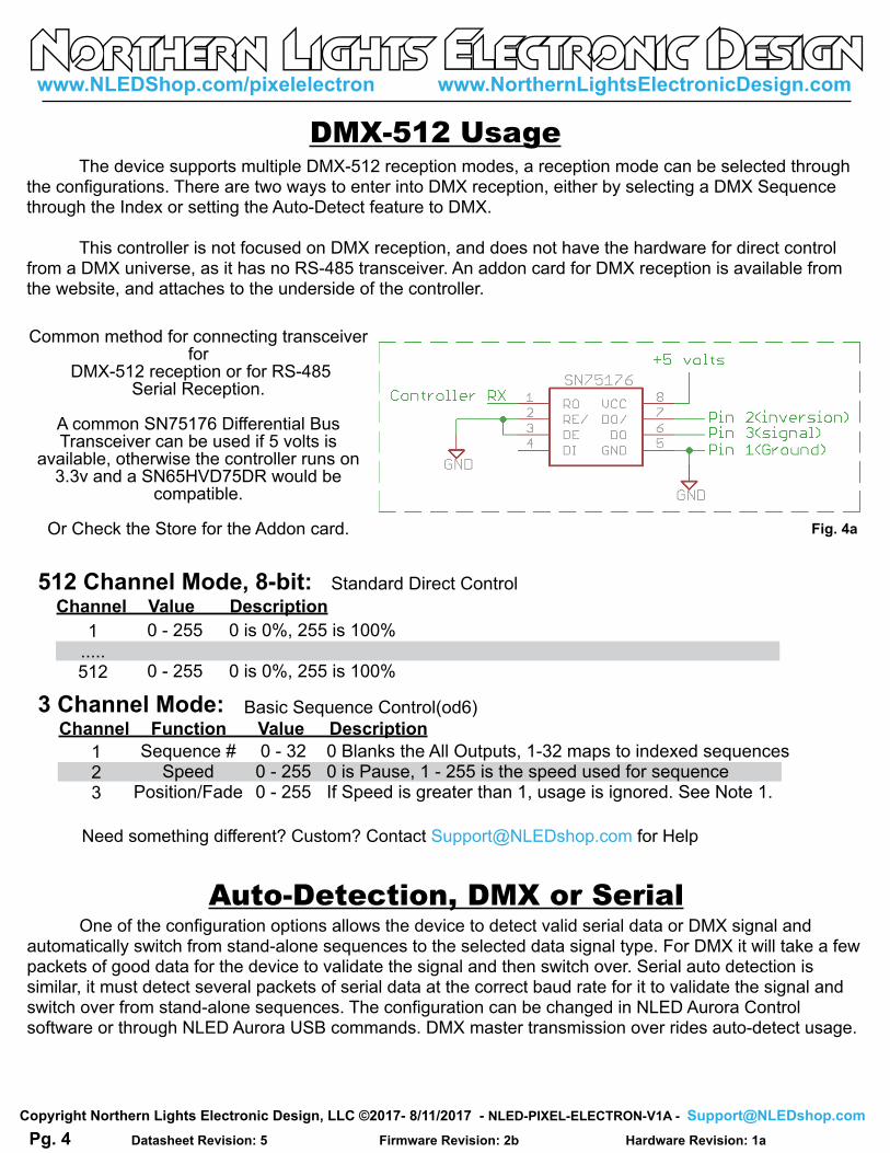
Auto-Detection, DMX or Serial One of the configuration options allows the device to detect valid serial data or DMX signal and automatically switch from stand-alone sequences to the selected data signal type. For DMX it will take a few packets of good data for the device to validate the signal and then switch over. Serial auto detection is similar, it must detect several packets of serial data at the correct baud rate for it to validate the signal and switch over from stand-alone sequences. The configuration can be changed in NLED Aurora Control software or through NLED Aurora USB commands. DMX master transmission over rides auto-detect usage.
1.....512
0 - 255
0 - 255
512 Channel Mode, 8-bit: Standard Direct Control
Need something different? Custom? Contact [email protected] for Help
Channel Value Description
DMX-512 Usage The device supports multiple DMX-512 reception modes, a reception mode can be selected through the configurations. There are two ways to enter into DMX reception, either by selecting a DMX Sequence through the Index or setting the Auto-Detect feature to DMX.
This controller is not focused on DMX reception, and does not have the hardware for direct control from a DMX universe, as it has no RS-485 transceiver. An addon card for DMX reception is available from the website, and attaches to the underside of the controller.
0 is 0%, 255 is 100%
0 is 0%, 255 is 100%
Common method for connecting transceiver for
DMX-512 reception or for RS-485Serial Reception.
A common SN75176 Differential Bus Transceiver can be used if 5 volts is
available, otherwise the controller runs on 3.3v and a SN65HVD75DR would be
compatible.
Or Check the Store for the Addon card. Fig. 4a
Basic Sequence Control(od6)
123
0 - 320 - 2550 - 255
Sequence #Speed
Position/Fade
0 Blanks the All Outputs, 1-32 maps to indexed sequences0 is Pause, 1 - 255 is the speed used for sequenceIf Speed is greater than 1, usage is ignored. See Note 1.
Serial reception can directly control the device’s outputs using a common serial transmission device. Such as a standard COM port with level translation, an FTDI adapter, Arduino, PIC UART, wireless XBee, or similar. The device receives data in packets, the size(in bytes) of the packet corresponds to how many channels will be controlled. Example: Sending a packet of 90 bytes will control 30 RGB pixels, sending 510 bytes would control 170 RGB pixels. There is a maximum of 5mS between bytes and a minimum of 5mS between packets(end-of-frame), to allow the data to latch. A delay between received data bytes of more than 5mS will reset the buffer pointer, framing the data. Partial packets will latch after the 5mS delay, or latching will occur immediately after receiving the last(512th) byte. Serial Reception can be enabled through the NLED Aurora Control software by adding it to an index, or by configuring auto-detection. Each method requires the use of the software. In the software, on the Hardware Tab, select the Auto-Detect Serial option to automatically enter Serial Reception when valid data is received. The device can take several packets to detect and validate the data before starting reception. The stock baud rate is 19,200, but the user can set the utilized baud rate using the software through the hardware tab by selecting the desired baud rate from the drop down menu. The byte formatting is the standard 8-N-1(8-bits, no parity, 1 stop bit) The controller accepts the data in regular RGB order and will reformat it to the required output order(to GRB, BRG etc) as per the configuration setting.
*Note: Percentage of error is within usable limits.
And won’t affect usage.
9,600
19,200
38,400
57,600
115,200
230,400
460,800
921,600
9,615
19,230
38,461
57,142
117,647
222,222
250,000
444,444
500,000
1,000,000
0.16%
0.16%
0.16%
0.64%
-0.79%
2.12%*
-3.55%*
8.51%
Closest
Common
Baud Rate
Actual
Device
Baud Error %
Fig. 5a
ID#
0
1
2
3
4
5
6
7
8
9
8-N-1
Serial Communication
As briefly mentioned in the NLED Aurora Control section this controller offers Dual Command Mode configuration(see Pg. xx). This allows the user to select wether to run the controller normally using USB as the primary communication port for commands and uploads. Or allow commands to be communicated from TTL serial devices and modules.
Disabled(Default): Aurora commands, such as sequence uploading and sequence control, can only be issued over the USB interface. All other serial and DMX functions work as normal.
Enabled: The controller will disable serial reception, DMX reception, and DMX master transmission. This allows for external TTL serial devices such as FTDI adapters, WiFi modules(X-Bee, ESP8266), Bluetooth modules, or Arduino’s to issue commands to the controller. The USB interface works concurrently with the external serial module and either can send and recieve commands.
Controller supports both 3.3 volt and 5 volt logic levels.
This device includes a bootloader feature. It allows the firmware on the device to be upgraded with new features and bug fixes using only an USB cable and a small computer program.
After the device is connected, please follow the instructions found at www.NLEDshop.com/bootloader. That is also where the software download links can be found.
Firmware Updates Using The Bootloader
Firmware updates are encrypted and protected with special code that prevents other devices from being programmed with the update firmware images. And prevents non-NLED firmwares from being programmed onto the devices. If a firmware image is loaded onto a microcontroller without the special protection code it will respond to commands and USB will work, but the outputs will be off . Contact Us for help restoring your device to original condition if your microcontroller was damaged, erased, ‘bricked’, or otherwise not working correctly.
Fig. 6a
The bootloader entry method is: - With the device powered off, while holding down the button or after making the jumper in Fig. 8a- Power up the device. Either by connecting the device to the computer with a USB cable. Or connect external power.- Wait a second or two. - The device’s notification LED should be full on if it entered bootloader mode and will blink steadily if in bootloader mode and successfully communicating with the host computer. When the software is started(or if it is already started) it will automatically connect to the device if one is found.
Or the device can enter the bootloader mode via USB commands. Either from NLED Aurora Control, using the button on the upper right on the Hardware Tab.
The command is:140 0 0 0 0
To Enter a command:- Open the correct COM port- Select any baud rate, doesn’t matter- Send as ASCII “NLED11”- Device will respond with “a9” - Send as ASCII “nled99”- Device will respond with “f0”- Send as Numbers “140 0 0 0 0”- Device will then enter bootloader mode(Note not all devices and firmware versions are compatbile)
Example shown is the third party software RealTerm.(NOT AFFILIATED)
The onboard accelerometer can be utilized for movement speed, movement detection, and double
tap presses. Its usage and function can be enabled or disabled through the configuration settings. Best for
flow toys such as poi, staves, and hoops. It also offers the ability to automatically turn off the controller when
not in use and to turn it back on when movement resumes. The configurations section on page 8 has the
details.
Automatic Shut Off/Resume & Time Out Value: This setting allows the device to detect when its not physically moving and shut off the LEDs/Pixels, saving power. Moving or shaking it will wake it back up and it will resume where it left off. Good for battery powered applications.
Enable Accelerometer Speed Adjustment: Option allows the controller to adjust the speed of POV and Instant color sequence based on the movemenet/rotation of the controller. Best or flow toy projects.
Enable Accelerometer Double Tap Button Press: Allows the controller to detect a user tapping the controller twice and will emulate a button press. Which would change the color sequence to the next one in the index. There are 3 sensitivity modes, from very sensitive to more robust.
Live Control & Aurora Command Protocol
Aurora compatible controllers have a specialized command set that is used to control and command the controller from the Aurora software or from user created software applications. It is a simple character exchange protocol based on ASCII and 8-bit numbers. Many NLED controllers have USB compatibility, the USB drivers make it appear as a standard legacy serial or COM port to computer. Other controllers may require a USB to Serial Adapter(such an FTDI) or other form of TTL(5 volt) serial converter in order to interface with the NLED controller. Some NLED controllers can use TTL serial and USB interchangeably and transparently to computer side software. The feature is listed as “Dual Command Mode” and must be selected through hardware configurations, it may interfere with other data communication methods such as DMX or Serial, see device datasheet. Whether the device is connected over USB or serial, the command protocol works the same and is transparent to the controller and software.
Any software language that can communicate with serial ports can interface with Aurora controllers. The command protocol is also so simple that commands can be issued from a serial terminal like RealTerm or HyperTerm.
Details and specifics can be found in the “NLED-Aurora-Control-Command-Sheet-vxx.pdf”
And an example software application can be found separately.
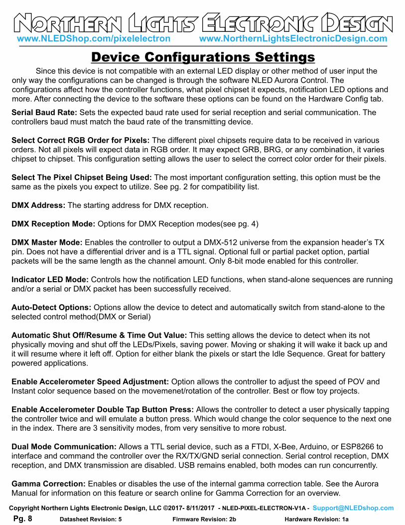
Since this device is not compatible with an external LED display or other method of user input the only way the configurations can be changed is through the software NLED Aurora Control. The configurations affect how the controller functions, what pixel chipset it expects, notification LED options and more. After connecting the device to the software these options can be found on the Hardware Config tab.
Device Configurations Settings
Serial Baud Rate: Sets the expected baud rate used for serial reception and serial communication. The controllers baud must match the baud rate of the transmitting device.
Select Correct RGB Order for Pixels: The different pixel chipsets require data to be received in various orders. Not all pixels will expect data in RGB order. It may expect GRB, BRG, or any combination, it varies chipset to chipset. This configuration setting allows the user to select the correct color order for their pixels.
Select The Pixel Chipset Being Used: The most important configuration setting, this option must be the same as the pixels you expect to utilize. See pg. 2 for compatibility list.
DMX Address: The starting address for DMX reception.
DMX Reception Mode: Options for DMX Reception modes(see pg. 4)
DMX Master Mode: Enables the controller to output a DMX-512 universe from the expansion header’s TX pin. Does not have a differential driver and is a TTL signal. Optional full or partial packet option, partial packets will be the same length as the channel amount. Only 8-bit mode enabled for this controller.
Indicator LED Mode: Controls how the notification LED functions, when stand-alone sequences are running and/or a serial or DMX packet has been successfully received.
Auto-Detect Options: Options allow the device to detect and automatically switch from stand-alone to the selected control method(DMX or Serial)
Automatic Shut Off/Resume & Time Out Value: This setting allows the device to detect when its not physically moving and shut off the LEDs/Pixels, saving power. Moving or shaking it will wake it back up and it will resume where it left off. Option for either blank the pixels or start the Idle Sequence. Great for battery powered applications.
Enable Accelerometer Speed Adjustment: Option allows the controller to adjust the speed of POV and Instant color sequence based on the movemenet/rotation of the controller. Best or flow toy projects.
Enable Accelerometer Double Tap Button Press: Allows the controller to detect a user physically tapping the controller twice and will emulate a button press. Which would change the color sequence to the next one in the index. There are 3 sensitivity modes, from very sensitive to more robust.
Dual Mode Communication: Allows a TTL serial device, such as a FTDI, X-Bee, Arduino, or ESP8266 to interface and command the controller over the RX/TX/GND serial connection. Serial control reception, DMX reception, and DMX transmission are disabled. USB remains enabled, both modes can run concurrently.
Gamma Correction: Enables or disables the use of the internal gamma correction table. See the Aurora Manual for information on this feature or search online for Gamma Correction for an overview.
The controller accepts an input voltage of 3.3 volts to 12 volts. The controller regulates the input voltage to 3.3v to power the MCU and peripherals. When connected over USB only the controller will be powered, it can be interfaced through the software without an external power connection. Depending on the pixel configuration, some or all of the pixels may attempt to function or will light up, but will not act properly until they receive an external power connection of the proper voltage. The controller must have adequately supplied power in order to function correctly. Using an under rated power supply or improper power distribution can cause the controller to function incorrectly or not at all.(Due to the controller receiving less than the minimum input voltage of 4 volts and browning-out or resetting) If a lower input voltage is required, the regulator can be bypassed and a direct input voltage of 2v to 3.3v could also be used by direct connection to the “3.3v” position. Voltages lower than 3.3v may not be compatible with the pixels.
The pixel amount and configuration must be considered when choosing a power supply. Ensure the power supply is of the proper voltage specified by the pixel manufacturer. Use the example formula to calculate the maximum amperage that would be required. This results with a the maximum value in amps that RGB(3 channels per pixel) pixels could draw if they were all turned on full intensity at the same time. Lower rated power supplies can and would work, but could result in problems such as unexpected controller resets or brown-outs, pixels acting strangely or not at all.
The required amperage rating can be estimated as follows:
Amount of Pixels x 60 = Required Rating in Milliamps, then add 10%, then divide by 1000 = Required Rating in Amps.
Ex: 170 WS2812B pixels, rated for 5 volts. 170 x 60mA = 10200mA, 10200 x 1.1 = 11220mA, 11220 / 1000 = 11.22 mA
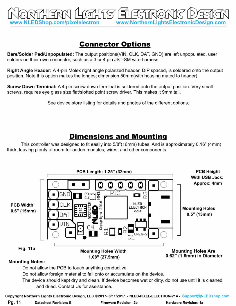
Do not allow the PCB to touch anything conductive.
Do not allow foreign material to fall onto or accumulate on the device.
The device should kept dry and clean. If device becomes wet or dirty, do not use until it is cleaned
and dried. Contact Us for assistance.
Mounting Holes Width
1.08” (27.5mm)
PCB Length: 1.25” (32mm)
Dimensions and Mounting
Mounting Holes Are 0.62” (1.6mm) in Diameter
Fig. 11a
Connector Options
Bare/Solder Pad/Unpopulated: The output positions(VIN, CLK, DAT, GND) are left unpopulated, user solders on their own connector, such as a 3 or 4 pin JST-SM wire harness.
Right Angle Header: A 4-pin Molex right angle polarized header, DIP spaced, is soldered onto the output position. Note this option makes the longest dimension 50mm(with housing mated to header)
Screw Down Terminal: A 4-pin screw down terminal is soldered onto the output position. Very small screws, requires eye glass size flat/slotted point screw driver. This makes it 9mm tall.
See device store listing for details and photos of the different options.
PCB Height
With USB Jack:
Approx: 4mm
This controller was designed to fit easily into 5/8”(16mm) tubes. And is approximately 0.16” (4mm) thick, leaving plenty of room for addon modules, wires, and other components.
Setup: It is recommended you also read the NLED Aurora Manual found in the download folder.1. Connect the controller to a computer using a micro USB cable.2. The controller is bus powered and should power up. Wait for the computer to load the driver(most systems should not need to install the driver or check the INF driver folder in the software folder). 4. Start the software, navigate to the hardware tab, on the left side select the controller’s COM port.5. The device should identify itself, and the Connect button should turn from red to green. The hardware configuration setting controls will also be displayed.6. Adjust the configuration setting controls on the Hardware Tab to suit your project see page 8 for details.7. Once the configuration settings are adjusted, navigate to the Connection Tab, and click the “Upload Configurations” button, you will be notified of a successful upload.8. Connect your LED pixels of choice as described on page 9.9. Apply suitable power to the controller and pixels, see page 10. The controller and pixels should start running a stand-alone color sequence, if not press the button or load new sequences.
Please Contact [email protected] with any Questions, Comments, or Bug Reports.
Have Any Ideas for Future Updates Northern Lights Electronic Design, LLC is constantly looking to make our products better and improve
upon our designs. If you have any ideas for future products, updates to current products, or features that you
would find useful, please Contact Us at [email protected]. There is a good chance your ideas could
be utilized, you could also receive coupons or free items for your feedback.
NLED is available to create new designs and deriatives of current designs customized to the clients
requirements, please Contact Us with your specifications.
Usage Instructions
Most issues can be resolved by power off the device, waiting a few seconds, and powering it back up.
Problem: Device with connected LEDs does not produce any light.
First ensure the LEDs are properly powered and wired to the controller and power source. Try to cycle
through the Sequences or modes using the button. And ensure you have selected the correct pixel chipset.
Problem: Device connected, LEDs are strobing or not working
Ensure you have selected then uploaded the correct Pixel Chipset configuration setting.
Problem: Device appears to be “bricked”, unresponsive to user inputs and/or communication(USB etc)
Attempt to upload a new firmware image via the Bootloader, see page 9 for details.
Problem: USB connection is not being established.
Check to make sure the USB cable is plugged and seated correctly. Check for connection via NLED Control
or your operating systems device manager, it should be listed as a COM port.
Problem: Operating systems indicates the driver can not be found.
The driver can be found possibly through Windows, or by locating and directing the operating system to the
INF driver file found in the NLED Aurora Control folder.