22
FlyingDream - v 0.00 – www.salrandazzo.it/fd 1 X-plane 11 – MD 82 Engine starting Tutorial Salvatore Randazzo
FlyingDream - v 0.00 – www.salrandazzo.it/fd 1
X-plane 11 – MD 82
Engine starting Tutorial Salvatore Randazzo

FlyingDream - v 0.00 – www.salrandazzo.it/fd 2
Why this tutorial
I always wanted to fly, but life broke my wings. I was too short-sighted to get the glider licence, and I had to
give up and switch to flight simulators.
I started with Sublogic or Microsoft (can’t remember) flight simulator on PC (DOS, of course!). We’re
talking about year 1990. The available airplane was a Cessna 172, just like now on x-plane. Sceneries were
so poor, just a little bit better than basic wire frame. But it was already a real emotion to push the throttle
and get aloft!, flying between the twin towers!
My hardware was really basic, i.e. a brand new Amstrad 1640. Airplane reactions to commands were so
slow that a real pilot told me that flying a real Cessna was much easier that flying the Simulated one.
I read a few books about how to fly, VFR, IFR and gliders. Just to understand how to use the simulator, even
thought my real dream was to fly for real, and not just in the passenger seat of some airliner.
To make a long story short, I built my own yoke, pedals and throttle and I spent so many hours reading
maps and learning how to fly VFR and IFR from Kennedy to La Guardia airport, and more.
Everything was quite easy, and then I started playing with clouds and wind, to make it harder.
Here I am, with my x-plane-11 demo copy. I want to play with it on my lap-top. Yes, I know that this
computer is too weak to support a real-time simulation. The frame rate is never above 11, and should be at
last 20. My plan is to learn the basics, then I’ll buy a complete x-plane-11 (xp11) licence and a computer
FlyingDream - v 0.00 – www.salrandazzo.it/fd 3
with good muscles, three monitors and some driving gadget like yoke, throttle and pedals at least. Then, if
passion won’t drop, some more instrument.
I already made my training with the default Cessna 172 plane. Easy to fly, easy to learn. In a couple of days
I learned by myself how to take off, fly and land in VFR mode using just the basic six gauges pack and VFR
maps.
Then I switched to IFR, learning how to use ADF, VOR, ILS and IFR maps.
Due to the fact that I’m using the demo version of the flight simulator program, my usual path is from
Tacoma KSEA airport to Olympia KOLM destination.
Feeling “expert” with the Cessna 172, I decided to switch to something more complicated, and the MD82
caught my attention.
The Mad Dog Family
The MD80 family got the “Mad Dog” nickname. There are many versions of the reason why the MD-80
family got this nickname. Someone says:
“It comes from the prefix M-D and it's easier to say than MD-80 on the radio. It sounds juvenile, but for
example, if Ground asks you to hold short of a taxiway to let an MD-80 pass, it's easier and quicker to
respond, "Ok, we'll give way to the mad dog," than to say, "Ok, we'll give way to the MD-80." That's the
only reason, and most pilots who commonly refer to MD-80s as mad dogs with any regularity are Atlantic
Southeast pilots in ATL who must yield to Delta's MD-88 fleet, and also the ASA pilots in DFW who must
work with both AA and DL MD-80s daily. Other than on the radio, I've never, ever heard an MD-80 aircraft
referred to as a "mad dog". It's just a playful use of the MD prefix.”
Panic
When first time I sat on the virtual left seat of the MD 82, I felt lost. Engines were already running, the
runway in front of me, flaps already at 15% ready for take-off. I pushed the throttle handle and heard
engines roaring, but nothing else happened. Panic. “Ok, ok, there is something missing. Brakes, of course!
Let’s find where is the handle”. But I didn’t find it, no leverage on the pedestal, where usually cars have it.
No handle under the cockpit, where the good old Cessna 172 has it. Believe it or not, I had to google for
“MD 82 parking brake”, so I discovered that it was there, near my left arm!
“Why didn’t you use the B key to toggle the parking brakes?”. Well, the thing is that I always want to play
with “real things”, as far as possible. There is no “B key” on a real MD 82, you’ve to know where the handle
is!
When I found the handle, I succeeded with my first MD 82 take-off. But then I thought “What if I want to
start from the scratch, with engines and everything else off? “. And this is the subject of this tutorial.

FlyingDream - v 0.00 – www.salrandazzo.it/fd 4
Absolute beginner
Please keep in mind that I’m not a professional pilot, nor an MD 82 expert. I’m just an absolute beginner,
and this is the spirit of this tutorial: to help other absolute beginners. Expert MD 82 pilots possibly will find
lot of errors, and I’ll be glad to receive their critics and to modify this pages according to their suggestions.
If you think that this tutorial could be useful, let me know (leave a comment on my website
www.salrandazzo.it/fd). Other tutorials are on the way to come.
Here I will try to explain how to start MD-82 engines using the APU and, more, I’ll try to explain how a jet
engine works.
FlyingDream - v 0.00 – www.salrandazzo.it/fd 5
Engine start procedure
Our procedure will start with all the engines off, electrical power off, and all valves closed, so that we’ll
have to describe the whole procedure step by step.
There will be no external power or compressed air, so that we’ll make use of the APU.
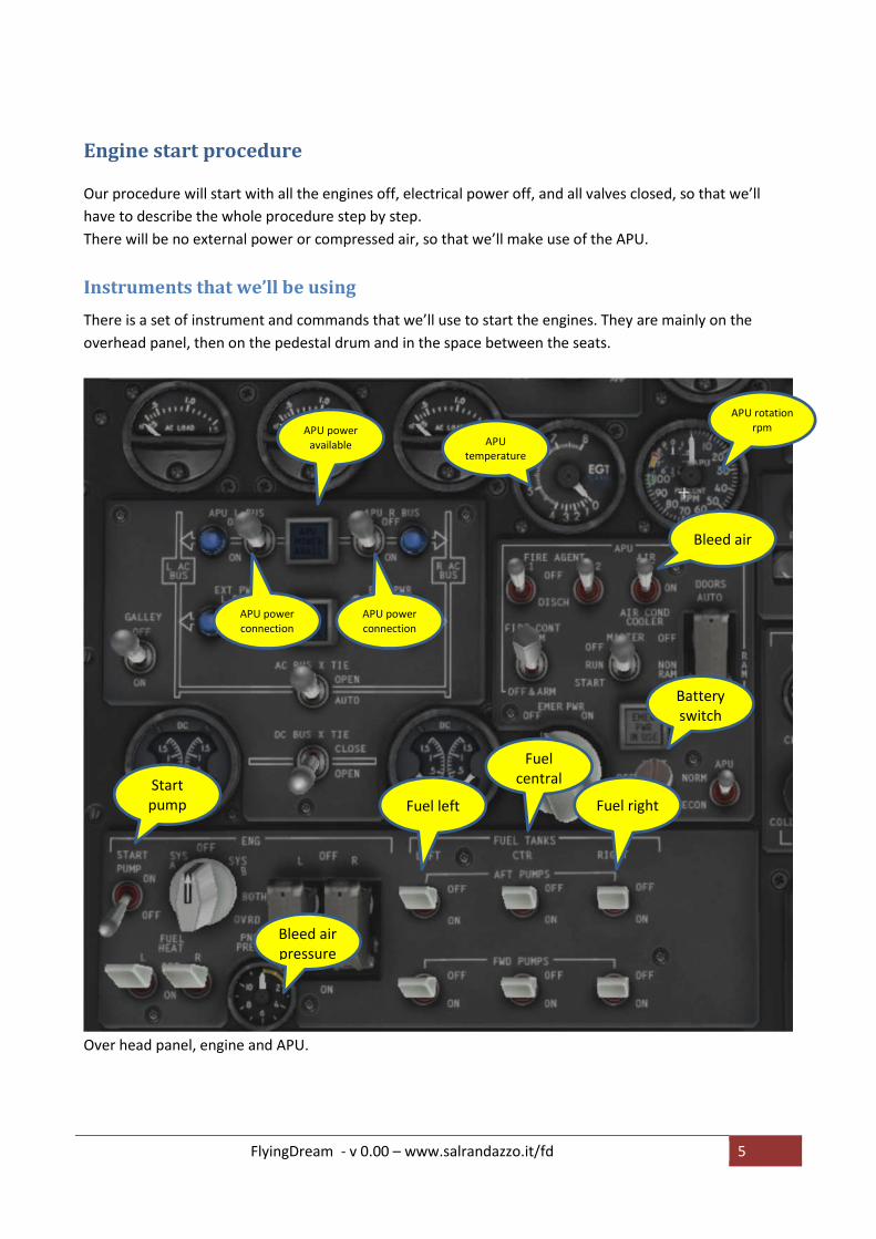
Instruments that we’ll be using
There is a set of instrument and commands that we’ll use to start the engines. They are mainly on the
overhead panel, then on the pedestal drum and in the space between the seats.
Over head panel, engine and APU.
Start pump
Battery switch
Bleed air
APU temperature
APU rotation rpm APU power
available
APU power connection
APU power connection
Fuel left
Fuel central
Fuel right
Bleed air pressure

FlyingDream - v 0.00 – www.salrandazzo.it/fd 6
Pedestal drum
Aft end of the pedestal, between the seats
Fuel valve left
Fuel valve right
Bleed air right
Bleed air left

FlyingDream - v 0.00 – www.salrandazzo.it/fd 7
Pre-start situation.
I f you want to make a complete engine start simulation, verify that each command is in its inactive state:
1. Battery switch off.
2. Start pump switch off
3. Bleed air swtich off.
4. APU main switch off
5. Start pump off
6. L & R APU AC BUS switches off
7. All six fuel tanks AFT and FWD switches off
8. L & R fuel handle at minimum position (fuel valve closed, no fuel)
9. L & R engine bleed air closed (no bleed air to/from engines
APU
The Auxiliary Power Unit is a turbine powered generator that supplies electrical power and compressed
(bleed) air when there is no ground assistance and engines are still off. When engines will be on, the APU
can be turned off because engines will provide both AC/DC power supply and compressed air.
When APU is on, it generates AC/DC energy to power all the instrument and bleed air to start the engines.
The APU is started using the airplane batteries.

FlyingDream - v 0.00 – www.salrandazzo.it/fd 8
Sequence
1. First we’ve to turn on the batteries, so that we’ll have energy enough to start the APU. Click on the
battery switch to put it in the ON position, then click again to secure the switch, just to avoid in-
flight unintentional power-off. With the battery switch ON all the
battery switch ON battery switch secured
2. With the battery switch ON some of the instrument will be powered, like the annunciator on the
overhead panel
3. Turn the start pump on
FlyingDream - v 0.00 – www.salrandazzo.it/fd 9
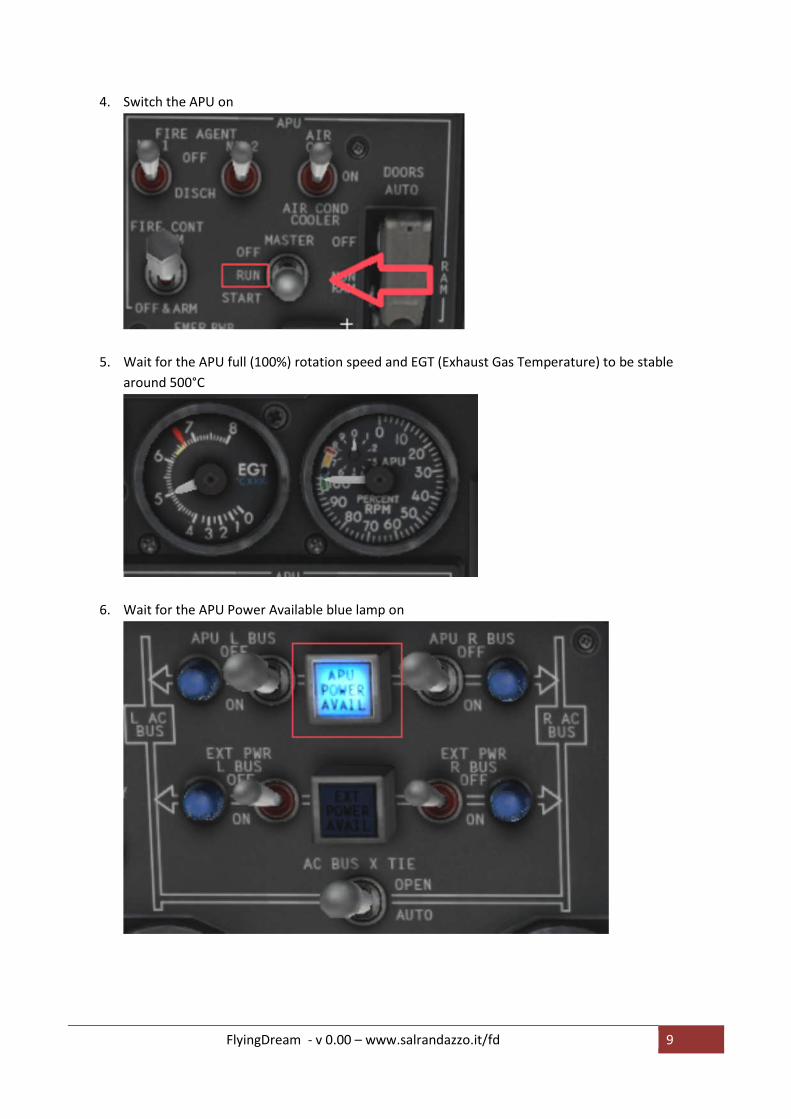
4. Switch the APU on
5. Wait for the APU full (100%) rotation speed and EGT (Exhaust Gas Temperature) to be stable
around 500°C
6. Wait for the APU Power Available blue lamp on
FlyingDream - v 0.00 – www.salrandazzo.it/fd 10
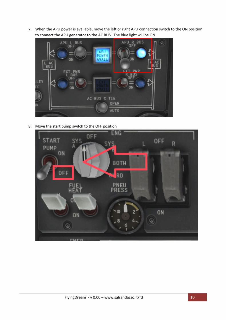
7. When the APU power is available, move the left or right APU connection switch to the ON position
to connect the APU generator to the AC BUS. The blue light will be ON
8. Move the start pump switch to the OFF position
FlyingDream - v 0.00 – www.salrandazzo.it/fd 11
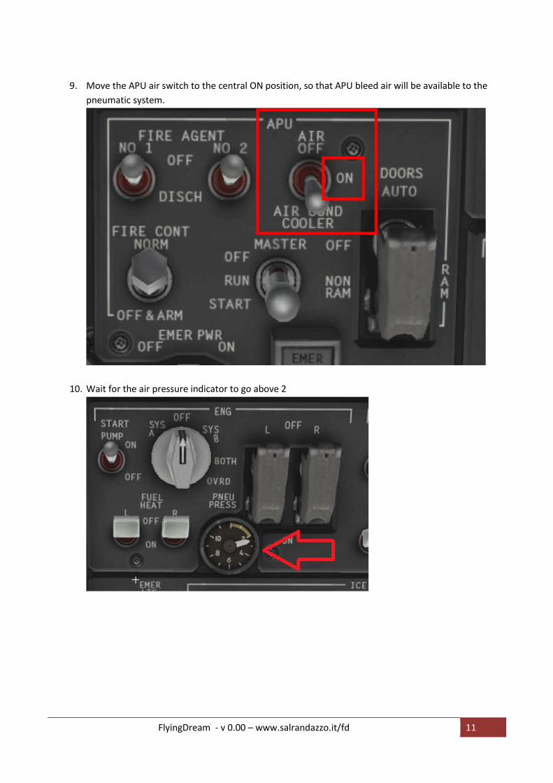
9. Move the APU air switch to the central ON position, so that APU bleed air will be available to the
pneumatic system.
10. Wait for the air pressure indicator to go above 2
FlyingDream - v 0.00 – www.salrandazzo.it/fd 12
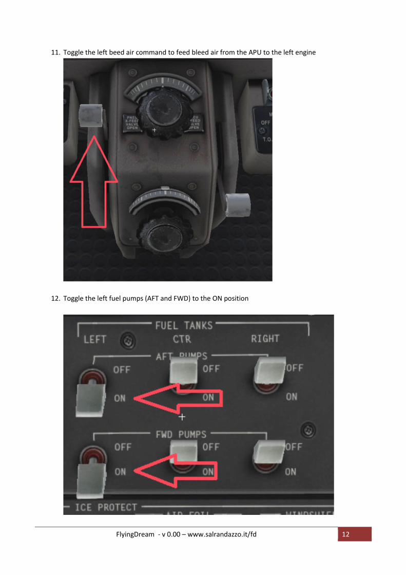
11. Toggle the left beed air command to feed bleed air from the APU to the left engine
12. Toggle the left fuel pumps (AFT and FWD) to the ON position
FlyingDream - v 0.00 – www.salrandazzo.it/fd 13
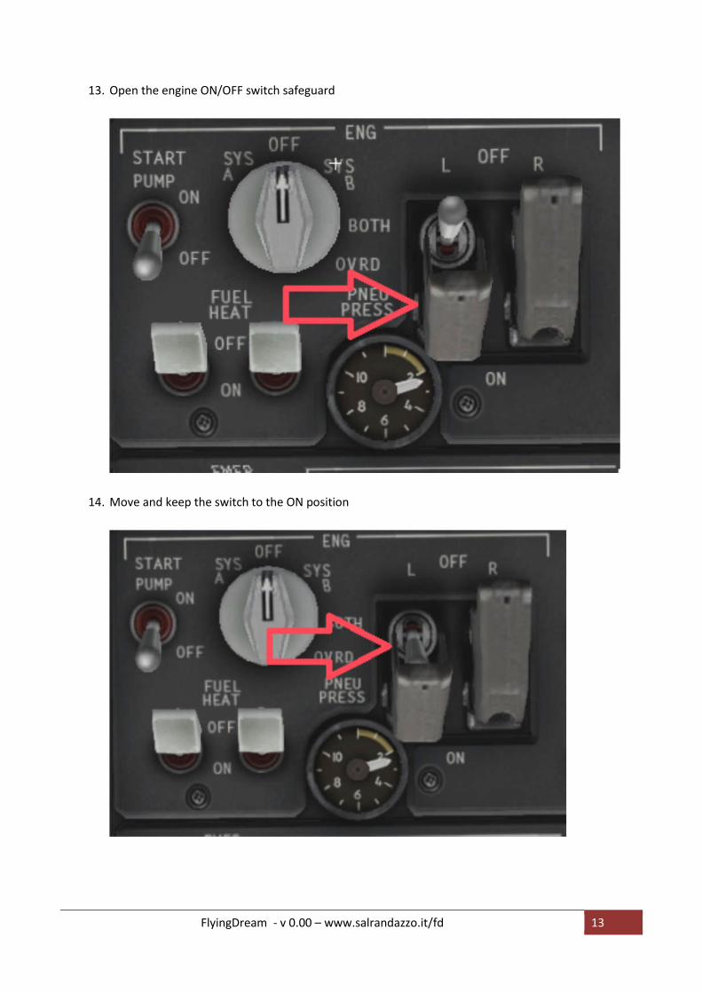
13. Open the engine ON/OFF switch safeguard
14. Move and keep the switch to the ON position
FlyingDream - v 0.00 – www.salrandazzo.it/fd 14
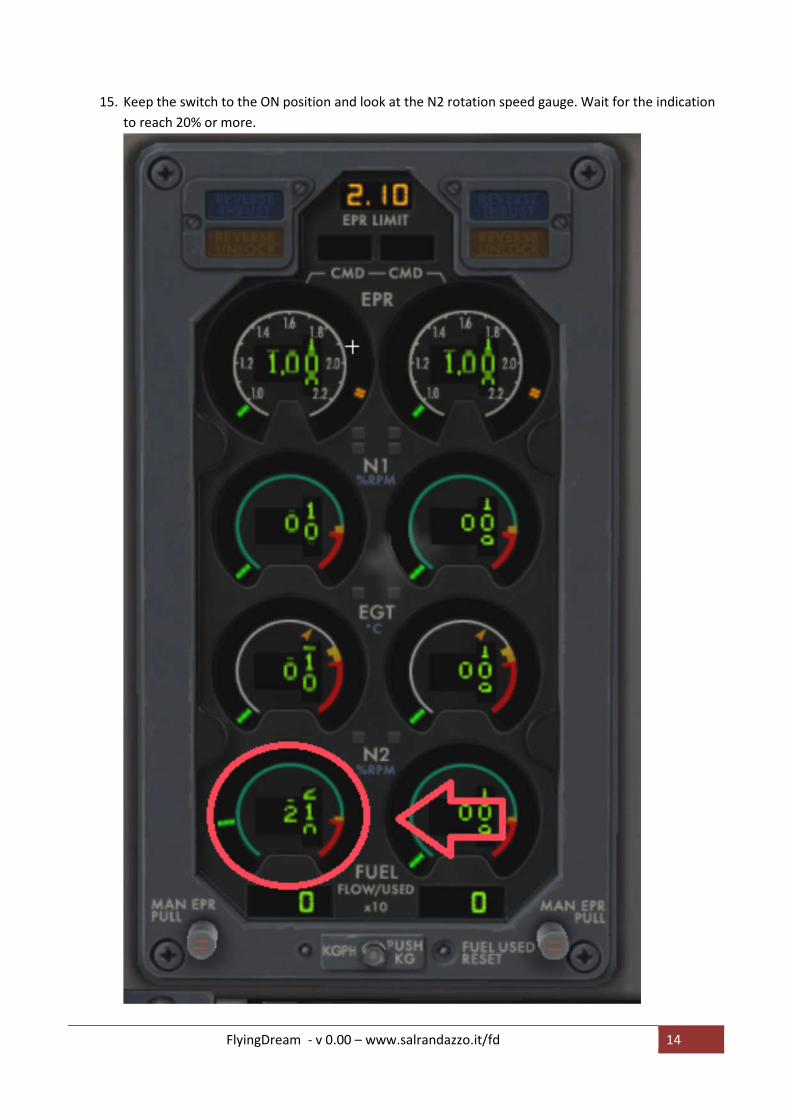
15. Keep the switch to the ON position and look at the N2 rotation speed gauge. Wait for the indication
to reach 20% or more.
FlyingDream - v 0.00 – www.salrandazzo.it/fd 15
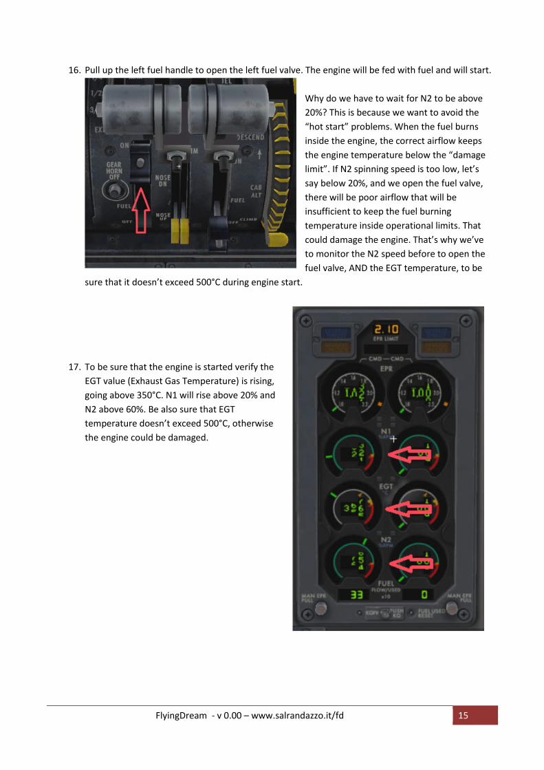
16. Pull up the left fuel handle to open the left fuel valve. The engine will be fed with fuel and will start.
Why do we have to wait for N2 to be above
20%? This is because we want to avoid the
“hot start” problems. When the fuel burns
inside the engine, the correct airflow keeps
the engine temperature below the “damage
limit”. If N2 spinning speed is too low, let’s
say below 20%, and we open the fuel valve,
there will be poor airflow that will be
insufficient to keep the fuel burning
temperature inside operational limits. That
could damage the engine. That’s why we’ve
to monitor the N2 speed before to open the
fuel valve, AND the EGT temperature, to be
sure that it doesn’t exceed 500°C during engine start.
17. To be sure that the engine is started verify the
EGT value (Exhaust Gas Temperature) is rising,
going above 350°C. N1 will rise above 20% and
N2 above 60%. Be also sure that EGT
temperature doesn’t exceed 500°C, otherwise
the engine could be damaged.

FlyingDream - v 0.00 – www.salrandazzo.it/fd 16
18. Repeat the same sequence for the right engine:
a. Open right bleed air
b. Switch on right fuel pumps
c. Open right engine start switch safeguard
d. Move right engine start switch to ON and keep it in this position
e. Wait for N2 > 20%
f. Open right fuel handle
g. Verify that N1>20%, N2>60%, EGT>350°C
19. Now that both engines are running, turn the APU off :
a. Start pump switch off
b. APU bleed air switch off
c. APU master switch off
d. APU L&R bus switch off
Set the Voltmeter Selector on L position and verify that AC volt > 120 and Freq > 400.
Repeat for the selector in the R position. This is to verify that both engines are generating AC power.
Now both your engines are ready to take you above the clouds!
There is, of course, still a long check list of parameters to be verified before your take off. But what we
did so far is just to start engines, and if you didn’t activate any failure, x-plane takes care that your
MD82 is ready to fly.

FlyingDream - v 0.00 – www.salrandazzo.it/fd 17
A bit of theory
Now that you know how to start the engine, a bit of theory could help you to understand what you do and
how it works. Our MD-82 is pushed by two Pratt & Whitney JT8D-217A/C turbofan engines.
Let’s understand how a jet engine works.
First of all you’ve FUEL.
When you burn fuel, you get exhaust gas.
Put fuel into a container and let it burn. Exhaust gas will generate high pressure. Put a nozzle at one end of
the container, and exhaust gas will escape from the container where the burning fuel is, generating a
thrust.
But fuel by itself doesn’t generate so much thrust. Experience says that it works much better if you mix fuel
and high pressure air.
Put a fan that pushes air into the container, mix fuel and burn. On the nozzle side you’ll have much more
pressure and much more thrust.
FlyingDream - v 0.00 – www.salrandazzo.it/fd 18
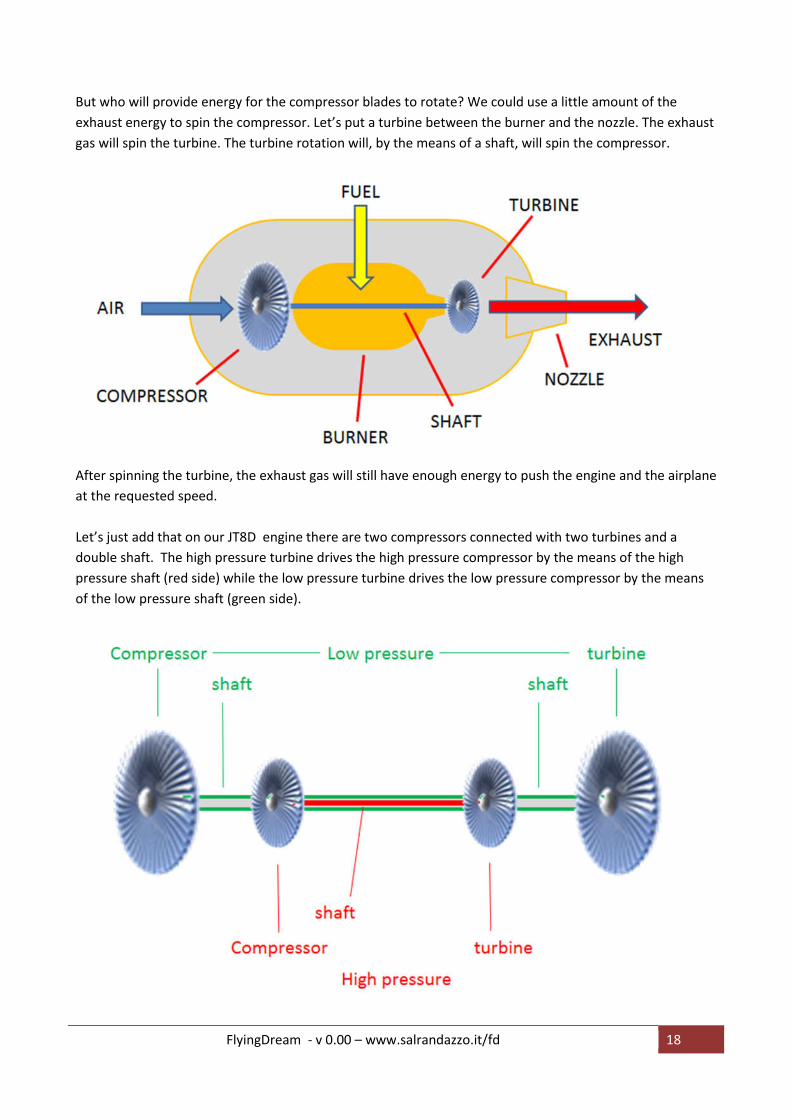
But who will provide energy for the compressor blades to rotate? We could use a little amount of the
exhaust energy to spin the compressor. Let’s put a turbine between the burner and the nozzle. The exhaust
gas will spin the turbine. The turbine rotation will, by the means of a shaft, will spin the compressor.
After spinning the turbine, the exhaust gas will still have enough energy to push the engine and the airplane
at the requested speed.
Let’s just add that on our JT8D engine there are two compressors connected with two turbines and a
double shaft. The high pressure turbine drives the high pressure compressor by the means of the high
pressure shaft (red side) while the low pressure turbine drives the low pressure compressor by the means
of the low pressure shaft (green side).
FlyingDream - v 0.00 – www.salrandazzo.it/fd 19
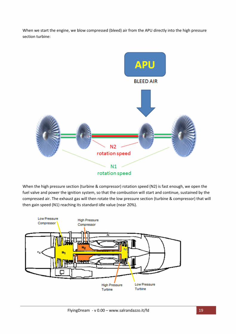
When we start the engine, we blow compressed (bleed) air from the APU directly into the high pressure
section turbine:
When the high pressure section (turbine & compressor) rotation speed (N2) is fast enough, we open the
fuel valve and power the ignition system, so that the combustion will start and continue, sustained by the
compressed air. The exhaust gas will then rotate the low pressure section (turbine & compressor) that will
then gain speed (N1) reaching its standard idle value (near 20%).

FlyingDream - v 0.00 – www.salrandazzo.it/fd 20
A turbofan engine works more or less like the piston engine of your car, following the four strokes schema:
1. Intake: the air comes in at the air intake stage
2. Compression: the air gets compressed by the compression section.
3. Combustion: fuel is added to the hot compressed air. The air/fuel mixture burns, producing a great
quantity of hot gas
4. Exhaust: the hot gas, passing through the turbine stage, produces the power to drive the
compressor stage (see stroke 2). Then the hot exhaust gas, getting out of the nozzle, gives the
thrust that pushes the airplane.
The main difference between your car engine and a JT8d turbofan is that the four “strokes” happen in a
continuous way, while in the piston engine they happen in different subsequent phases.
Compressors and turbines are just like a fan,
but there are a lot of subsequent stages. On
compressors, each stage pushes the air a bit
more, to the next stage that will push even
more and son on. The compressor has to be
driven by some kind of engine that gives the energy.
The turbine acts in a reverse way: hot exhaust gas, coming from the
combustion chamber, pushes the blades. As we saw above, just after the combustion chamber the gas will
have a great pressure that will be enough to spin turbines and to give the thrust to push the airplane.
1
2
3 4

FlyingDream - v 0.00 – www.salrandazzo.it/fd 21
Conclusion
This tutorial is just the first one of a series about using MD 82 with x-plane (v11). I used the English
language because we all know that this is somehow the “official language” of the flying world.
Unfortunately my ability with this language is not so good, because I never studied it at school time. That’s
why every correction and advice will be welcome.
I’m sure that real MD-82 pilots will find lot of mistakes. Please let me know about them, and I’ll do my best
to correct this tutorial.
Please, email me at [email protected] or leave a comment on my website www.salrandazzo.it/fd
Look at my website www.salrandazzo.it/fd for updates.

FlyingDream - v 0.00 – www.salrandazzo.it/fd 22
Release history
V 0.0 20-may-2017 Original document.


