124
Partial Reconfiguration User Guide UG702 (v14.1) April 24, 2012
[Guide Subtitle] [optional]
UG702 (v14.1) April 24, 2012 [optional]
Partial ReconfigurationUser Guide
UG702 (v14.1) April 24, 2012

Partial Reconfiguration User Guide www.xilinx.com UG702 (v14.1) April 24, 2012
Xilinx is disclosing this user guide, manual, release note, and/or specification (the “Documentation”) to you solely for use in the development of designs to operate with Xilinx hardware devices. You may not reproduce, distribute, republish, download, display, post, or transmit the Documentation in any form or by any means including, but not limited to, electronic, mechanical, photocopying, recording, or otherwise, without the prior written consent of Xilinx. Xilinx expressly disclaims any liability arising out of your use of the Documentation. Xilinx reserves the right, at its sole discretion, to change the Documentation without notice at any time. Xilinx assumes no obligation to correct any errors contained in the Documentation, or to advise you of any corrections or updates. Xilinx expressly disclaims any liability in connection with technical support or assistance that may be provided to you in connection with the Information.
THE DOCUMENTATION IS DISCLOSED TO YOU “AS-IS” WITH NO WARRANTY OF ANY KIND. XILINX MAKES NO OTHER WARRANTIES, WHETHER EXPRESS, IMPLIED, OR STATUTORY, REGARDING THE DOCUMENTATION, INCLUDING ANY WARRANTIES OF MERCHANTABILITY, FITNESS FOR A PARTICULAR PURPOSE, OR NONINFRINGEMENT OF THIRD-PARTY RIGHTS. IN NO EVENT WILL XILINX BE LIABLE FOR ANY CONSEQUENTIAL, INDIRECT, EXEMPLARY, SPECIAL, OR INCIDENTAL DAMAGES, INCLUDING ANY LOSS OF DATA OR LOST PROFITS, ARISING FROM YOUR USE OF THE DOCUMENTATION.
CRITICAL APPLICATIONS DISCLAIMERXILINX PRODUCTS (INCLUDING HARDWARE, SOFTWARE AND/OR IP CORES) ARE NOT DESIGNED OR INTENDED TO BE FAIL-SAFE, OR FOR USE IN ANY APPLICATION REQUIRING FAIL-SAFE PERFORMANCE, SUCH AS IN LIFE-SUPPORT OR SAFETY DEVICES OR SYSTEMS, CLASS III MEDICAL DEVICES, NUCLEAR FACILITIES, APPLICATIONS RELATED TO THE DEPLOYMENT OF AIRBAGS, OR ANY OTHER APPLICATIONS THAT COULD LEAD TO DEATH, PERSONAL INJURY OR SEVERE PROPERTY OR ENVIRONMENTAL DAMAGE (INDIVIDUALLY AND COLLECTIVELY, “CRITICAL APPLICATIONS”). FURTHERMORE, XILINX PRODUCTS ARE NOT DESIGNED OR INTENDED FOR USE IN ANY APPLICATIONS THAT AFFECT CONTROL OF A VEHICLE OR AIRCRAFT, UNLESS THERE IS A FAIL-SAFE OR REDUNDANCY FEATURE (WHICH DOES NOT INCLUDE USE OF SOFTWARE IN THE XILINX DEVICE TO IMPLEMENT THE REDUNDANCY) AND A WARNING SIGNAL UPON FAILURE TO THE OPERATOR. CUSTOMER AGREES, PRIOR TO USING OR DISTRIBUTING ANY SYSTEMS THAT INCORPORATE XILINX PRODUCTS, TO THOROUGHLY TEST THE SAME FOR SAFETY PURPOSES. TO THE MAXIMUM EXTENT PERMITTED BY APPLICABLE LAW, CUSTOMER ASSUMES THE SOLE RISK AND LIABILITY OF ANY USE OF XILINX PRODUCTS IN CRITICAL APPLICATIONS.
AUTOMOTIVE APPLICATIONS DISCLAIMERXILINX PRODUCTS ARE NOT DESIGNED OR INTENDED TO BE FAIL-SAFE, OR FOR USE IN ANY APPLICATION REQUIRING FAIL-SAFE PERFORMANCE, SUCH AS APPLICATIONS RELATED TO: (I) THE DEPLOYMENT OF AIRBAGS, (II) CONTROL OF A VEHICLE, UNLESS THERE IS A FAIL-SAFE OR REDUNDANCY FEATURE (WHICH DOES NOT INCLUDE USE OF SOFTWARE IN THE XILINX DEVICE TO IMPLEMENT THE REDUNDANCY) AND A WARNING SIGNAL UPON FAILURE TO THE OPERATOR, OR (III) USES THAT COULD LEAD TO DEATH OR PERSONAL INJURY. CUSTOMER ASSUMES THE SOLE RISK AND LIABILITY OF ANY USE OF XILINX PRODUCTS IN SUCH APPLICATIONS.
© Copyright 2012 Xilinx, Inc. XILINX, the Xilinx logo, Virtex, Spartan, ISE, and other designated brands included herein are trademarks of Xilinx in the United States and other countries. All other trademarks are the property of their respective owners.
UG702 (v14.1) April 24, 2012 www.xilinx.com Partial Reconfiguration User Guide
Revision HistoryThe following table shows the revision history for this document.
Date Version Revision
05/03/10 12.1 Initial release for ISE 12.1
07/23/10 12.2 Revisions to manual for ISE 12.2 release.
10/05/10 12.3 Revisions to manual for ISE 12.3 release.
03/01/11 13.1 Revisions to manual for ISE 13.1 release.
07/06/11 13.2 Revisions to manual for ISE 13.2 release:
• Additions throughout manual to indicate 7 Series PR support and to document how PR features apply to 7 series devices.
• Documented use of -g USR_ACCESS option to BitGen in PR flow.• Documented rules applicable to PR flow for stacked silicon interconnect (SSI) devices.• Updated regional clocking description as it applies to 7 series devices.• Updated known issues and known limitations for 13.2 release.• Reordered documentation list in Additional Resources appendix.
10/19/11 13.3 Revisions to manual for ISE 13.3 release:
• In Chapter 4, PlanAhead Support, modified procedures to conform to 13.3 PlanAhead design flow.
• In Chapter 4, PlanAhead Support, updated dialog box figures to reflect 13.3 versions of dialog boxes.
• Added information that a local reset must be issued to reconfigured logic to Design Requirements and Guidelines in Chapter 1.
• Added method by which command line users can save data about previously promoted Configurations. See Partitions and Import in Chapter 3.
01/18/12 13.4 Revisions to manual for ISE 13.4 release.
• Removed all references to SSI device support.
• Updated list of supported devices in Design Requirements and Guidelines section.
• Updated list of logic that must be placed in static logic and must not be placed in an RP. See Design Elements Inside Reconfigurable Modules.
• Added clarification to some issues in the Partial Reconfiguration Design Checklist section. Added information about resetting logic in an RM after reconfiguration.
04/24/12 14.1 Revisions to manual for ISE 14.1 release.
• Updated list of supported devices in Design Requirements and Guidelines section.
• In Chapter 4, PlanAhead Support, updated PlanAhead interface and dialog box figures to reflect 14.1 versions of interface and dialog boxes.
• Updated information about additional logic that cannot be placed in a reconfigurable partition. Removed all references to IO blocks and MGTs in RPs.
• Added information about BRAMs and FIFOS to Known Limitations section.

Partial Reconfiguration User Guide www.xilinx.com UG702 (v14.1) April 24, 2012

Partial Reconfiguration User Guide www.xilinx.com 5UG702 (v14.1) April 24, 2012
Revision History . . . . . . . . . . . . . . . . . . . . . . . . . . . . . . . . . . . . . . . . . . . . . . . . . . . . . . . . . . . . . 3
Chapter 1: IntroductionPartial Reconfiguration Overview . . . . . . . . . . . . . . . . . . . . . . . . . . . . . . . . . . . . . . . . . . . . 7Terminology . . . . . . . . . . . . . . . . . . . . . . . . . . . . . . . . . . . . . . . . . . . . . . . . . . . . . . . . . . . . . . . . . 8Partial Reconfiguration Design Criteria for ISE 14.1. . . . . . . . . . . . . . . . . . . . . . . . . . 10
Chapter 2: Common ApplicationsNetworked Multiport Interface . . . . . . . . . . . . . . . . . . . . . . . . . . . . . . . . . . . . . . . . . . . . . . 13Configuration by Means of PCIe Interface . . . . . . . . . . . . . . . . . . . . . . . . . . . . . . . . . . . 15Dynamically Reconfigurable Packet Processor . . . . . . . . . . . . . . . . . . . . . . . . . . . . . . . 16Asymmetric Key Encryption. . . . . . . . . . . . . . . . . . . . . . . . . . . . . . . . . . . . . . . . . . . . . . . . . 17Summary . . . . . . . . . . . . . . . . . . . . . . . . . . . . . . . . . . . . . . . . . . . . . . . . . . . . . . . . . . . . . . . . . . . 18
Chapter 3: Software Tools FlowExample Design Structure . . . . . . . . . . . . . . . . . . . . . . . . . . . . . . . . . . . . . . . . . . . . . . . . . . . 20Example Project File Structure . . . . . . . . . . . . . . . . . . . . . . . . . . . . . . . . . . . . . . . . . . . . . . . 21Synthesis . . . . . . . . . . . . . . . . . . . . . . . . . . . . . . . . . . . . . . . . . . . . . . . . . . . . . . . . . . . . . . . . . . . 22Configurations . . . . . . . . . . . . . . . . . . . . . . . . . . . . . . . . . . . . . . . . . . . . . . . . . . . . . . . . . . . . . . 23Constraints . . . . . . . . . . . . . . . . . . . . . . . . . . . . . . . . . . . . . . . . . . . . . . . . . . . . . . . . . . . . . . . . . 24Partitions and Import . . . . . . . . . . . . . . . . . . . . . . . . . . . . . . . . . . . . . . . . . . . . . . . . . . . . . . . 33Implementation . . . . . . . . . . . . . . . . . . . . . . . . . . . . . . . . . . . . . . . . . . . . . . . . . . . . . . . . . . . . . 36Generating BIT Files . . . . . . . . . . . . . . . . . . . . . . . . . . . . . . . . . . . . . . . . . . . . . . . . . . . . . . . . 38Report Files . . . . . . . . . . . . . . . . . . . . . . . . . . . . . . . . . . . . . . . . . . . . . . . . . . . . . . . . . . . . . . . . . 39pr_verify . . . . . . . . . . . . . . . . . . . . . . . . . . . . . . . . . . . . . . . . . . . . . . . . . . . . . . . . . . . . . . . . . . . . 48Flow Differences . . . . . . . . . . . . . . . . . . . . . . . . . . . . . . . . . . . . . . . . . . . . . . . . . . . . . . . . . . . . 51
Chapter 4: PlanAhead SupportCreating a Partial Reconfiguration Project . . . . . . . . . . . . . . . . . . . . . . . . . . . . . . . . . . . 53Setting the Project as a PR Project . . . . . . . . . . . . . . . . . . . . . . . . . . . . . . . . . . . . . . . . . . . 55Opening the Netlist Design . . . . . . . . . . . . . . . . . . . . . . . . . . . . . . . . . . . . . . . . . . . . . . . . . 56Defining the Reconfigurable Instances . . . . . . . . . . . . . . . . . . . . . . . . . . . . . . . . . . . . . . 57Adding Reconfigurable Modules to the Project . . . . . . . . . . . . . . . . . . . . . . . . . . . . . . 59Running Partial Reconfiguration Design Rule Checks . . . . . . . . . . . . . . . . . . . . . . . 66Creating Configurations. . . . . . . . . . . . . . . . . . . . . . . . . . . . . . . . . . . . . . . . . . . . . . . . . . . . . 67Controlling Configurations. . . . . . . . . . . . . . . . . . . . . . . . . . . . . . . . . . . . . . . . . . . . . . . . . . 70Verifying Configurations . . . . . . . . . . . . . . . . . . . . . . . . . . . . . . . . . . . . . . . . . . . . . . . . . . . 75Generating BIT Files . . . . . . . . . . . . . . . . . . . . . . . . . . . . . . . . . . . . . . . . . . . . . . . . . . . . . . . . 77PlanAhead Project Directory Structure. . . . . . . . . . . . . . . . . . . . . . . . . . . . . . . . . . . . . . . 78
Table of Contents
6 www.xilinx.com Partial Reconfiguration User GuideUG702 (v14.1) April 24, 2012
Chapter 5: Command Line ScriptingTcl Scripts . . . . . . . . . . . . . . . . . . . . . . . . . . . . . . . . . . . . . . . . . . . . . . . . . . . . . . . . . . . . . . . . . . 79Data.tcl Format . . . . . . . . . . . . . . . . . . . . . . . . . . . . . . . . . . . . . . . . . . . . . . . . . . . . . . . . . . . . . . 80Recommended Flow. . . . . . . . . . . . . . . . . . . . . . . . . . . . . . . . . . . . . . . . . . . . . . . . . . . . . . . . . 85Required Files and Directory Structure . . . . . . . . . . . . . . . . . . . . . . . . . . . . . . . . . . . . . . 86
Chapter 6: Configuring the FPGA DeviceConfiguration Modes . . . . . . . . . . . . . . . . . . . . . . . . . . . . . . . . . . . . . . . . . . . . . . . . . . . . . . . 90Downloading a Full Bit File . . . . . . . . . . . . . . . . . . . . . . . . . . . . . . . . . . . . . . . . . . . . . . . . . 90Downloading a Partial Bit File. . . . . . . . . . . . . . . . . . . . . . . . . . . . . . . . . . . . . . . . . . . . . . . 91System Design for Configuring an FPGA Device . . . . . . . . . . . . . . . . . . . . . . . . . . . . 92Partial Bit File Integrity . . . . . . . . . . . . . . . . . . . . . . . . . . . . . . . . . . . . . . . . . . . . . . . . . . . . . 93Partial Bitstream CRC Checking . . . . . . . . . . . . . . . . . . . . . . . . . . . . . . . . . . . . . . . . . . . . . 94Configuration Frames . . . . . . . . . . . . . . . . . . . . . . . . . . . . . . . . . . . . . . . . . . . . . . . . . . . . . . . 95Configuration Time . . . . . . . . . . . . . . . . . . . . . . . . . . . . . . . . . . . . . . . . . . . . . . . . . . . . . . . . . 96Configuration Debugging . . . . . . . . . . . . . . . . . . . . . . . . . . . . . . . . . . . . . . . . . . . . . . . . . . . 97
Chapter 7: Design ConsiderationsDesign Hierarchy . . . . . . . . . . . . . . . . . . . . . . . . . . . . . . . . . . . . . . . . . . . . . . . . . . . . . . . . . . 101Global Clocking Rules . . . . . . . . . . . . . . . . . . . . . . . . . . . . . . . . . . . . . . . . . . . . . . . . . . . . . 104Active Low Resets and Clock Enables . . . . . . . . . . . . . . . . . . . . . . . . . . . . . . . . . . . . . . 105Decoupling Functionality . . . . . . . . . . . . . . . . . . . . . . . . . . . . . . . . . . . . . . . . . . . . . . . . . . 105Design Revision Checks. . . . . . . . . . . . . . . . . . . . . . . . . . . . . . . . . . . . . . . . . . . . . . . . . . . . 106Defining Reconfigurable Partition Boundaries . . . . . . . . . . . . . . . . . . . . . . . . . . . . . 106Proxy Logic . . . . . . . . . . . . . . . . . . . . . . . . . . . . . . . . . . . . . . . . . . . . . . . . . . . . . . . . . . . . . . . . 107Black Boxes . . . . . . . . . . . . . . . . . . . . . . . . . . . . . . . . . . . . . . . . . . . . . . . . . . . . . . . . . . . . . . . . 108Module-Level Constraint Files . . . . . . . . . . . . . . . . . . . . . . . . . . . . . . . . . . . . . . . . . . . . . 108Implementation Strategies . . . . . . . . . . . . . . . . . . . . . . . . . . . . . . . . . . . . . . . . . . . . . . . . . 109Simulation and Verification . . . . . . . . . . . . . . . . . . . . . . . . . . . . . . . . . . . . . . . . . . . . . . . . 109Using High Speed Transceivers . . . . . . . . . . . . . . . . . . . . . . . . . . . . . . . . . . . . . . . . . . . . 110Interaction with Other Xilinx Tools . . . . . . . . . . . . . . . . . . . . . . . . . . . . . . . . . . . . . . . . . 110Partial Reconfiguration Design Checklist . . . . . . . . . . . . . . . . . . . . . . . . . . . . . . . . . . . 112
Appendix A: Known Issues and Known LimitationsKnown Issues . . . . . . . . . . . . . . . . . . . . . . . . . . . . . . . . . . . . . . . . . . . . . . . . . . . . . . . . . . . . . . 115Known Limitations . . . . . . . . . . . . . . . . . . . . . . . . . . . . . . . . . . . . . . . . . . . . . . . . . . . . . . . . 115
Appendix B: Partial Reconfiguration Migration GuideDifferences Between the Early Access and Production Solutions . . . . . . . . . . . . 117Migrating a Design. . . . . . . . . . . . . . . . . . . . . . . . . . . . . . . . . . . . . . . . . . . . . . . . . . . . . . . . . 119Summary . . . . . . . . . . . . . . . . . . . . . . . . . . . . . . . . . . . . . . . . . . . . . . . . . . . . . . . . . . . . . . . . . . 122
Appendix C: Additional Resources
Partial Reconfiguration User Guide www.xilinx.com 7UG702 (v14.1) April 24, 2012
Chapter 1
Introduction
Partial Reconfiguration is the modification of an operating FPGA design by loading a partial configuration file. This guide describes how to create and implement an FPGA design that is partially reconfigurable using a modular design technique called Partitioning. Module instances in the design are translated into partial BIT files which define the new hardware function. Other techniques such as the differencing method described in the Application Note: Differencing Method for Partial Reconfiguration (XAPP290) are not covered in this guide. For supplemental material, see Appendix C, Additional Resources.
This guide:
• Is intended for designers who want to create a Partially Reconfigurable FPGA design.
• Assumes familiarity with FPGA design software, particularly Xilinx® ISE® Design Suite and the PlanAhead™ toolset.
• Has been written specifically for ISE Design Suite Release 14.1. This release supports Partial Reconfiguration for Virtex®-4, Virtex-5, Virtex-6, Artix™-7, Kintex™-7, and Virtex-7 devices only.
• Describes Partial Reconfiguration as implemented in the ISE/PlanAhead toolset. Partial Reconfiguration is not currently supported in the Vivado Design Suite.
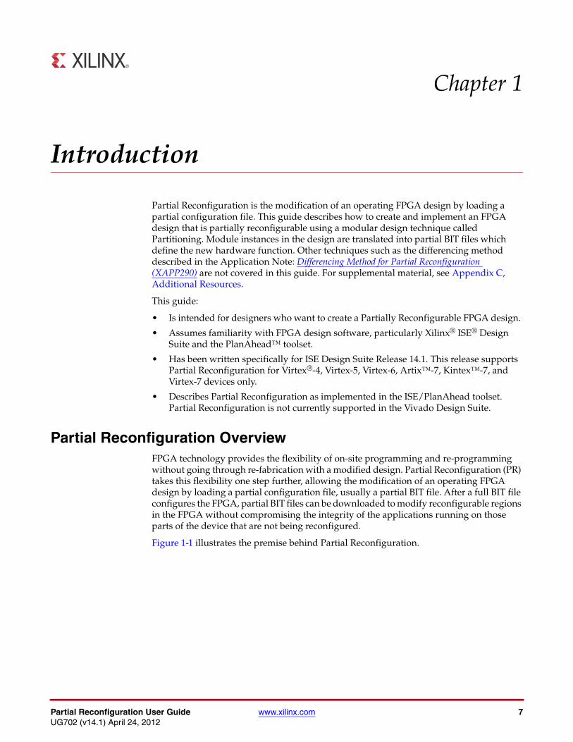
Partial Reconfiguration OverviewFPGA technology provides the flexibility of on-site programming and re-programming without going through re-fabrication with a modified design. Partial Reconfiguration (PR) takes this flexibility one step further, allowing the modification of an operating FPGA design by loading a partial configuration file, usually a partial BIT file. After a full BIT file configures the FPGA, partial BIT files can be downloaded to modify reconfigurable regions in the FPGA without compromising the integrity of the applications running on those parts of the device that are not being reconfigured.
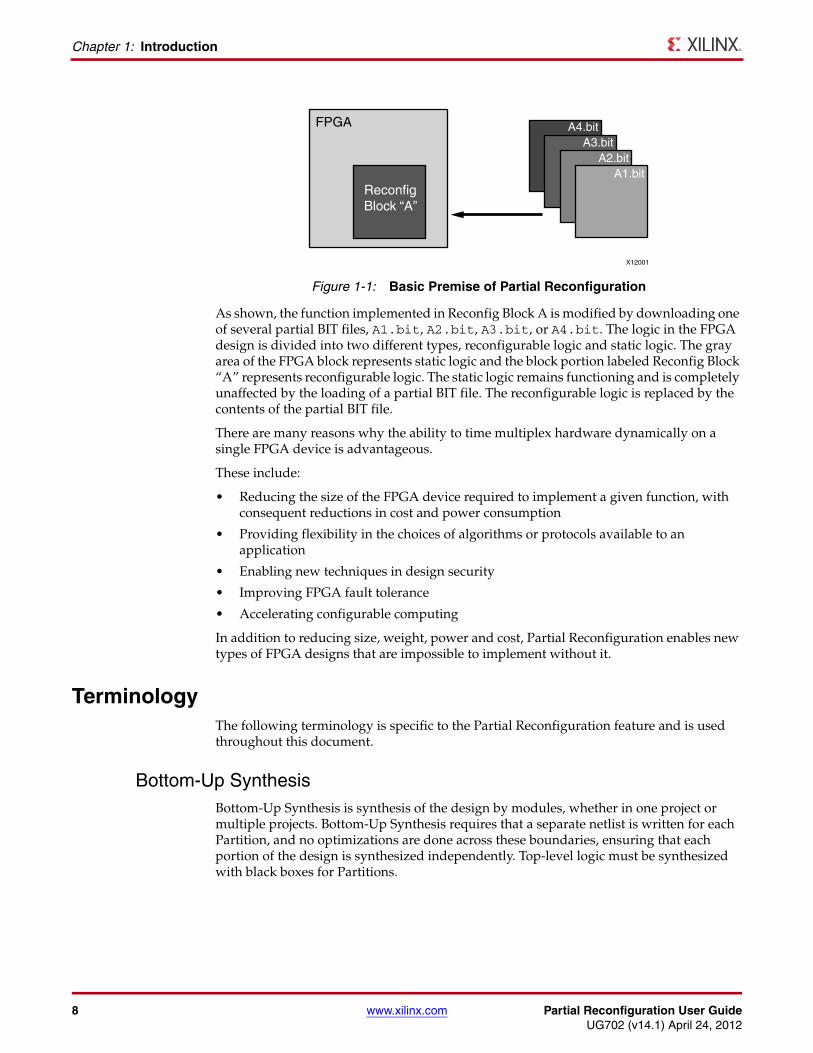
Figure 1-1 illustrates the premise behind Partial Reconfiguration.
8 www.xilinx.com Partial Reconfiguration User GuideUG702 (v14.1) April 24, 2012
Chapter 1: Introduction
As shown, the function implemented in Reconfig Block A is modified by downloading one of several partial BIT files, A1.bit, A2.bit, A3.bit, or A4.bit. The logic in the FPGA design is divided into two different types, reconfigurable logic and static logic. The gray area of the FPGA block represents static logic and the block portion labeled Reconfig Block “A” represents reconfigurable logic. The static logic remains functioning and is completely unaffected by the loading of a partial BIT file. The reconfigurable logic is replaced by the contents of the partial BIT file.
There are many reasons why the ability to time multiplex hardware dynamically on a single FPGA device is advantageous.
These include:
• Reducing the size of the FPGA device required to implement a given function, with consequent reductions in cost and power consumption
• Providing flexibility in the choices of algorithms or protocols available to an application
• Enabling new techniques in design security
• Improving FPGA fault tolerance
• Accelerating configurable computing
In addition to reducing size, weight, power and cost, Partial Reconfiguration enables new types of FPGA designs that are impossible to implement without it.
TerminologyThe following terminology is specific to the Partial Reconfiguration feature and is used throughout this document.
Bottom-Up SynthesisBottom-Up Synthesis is synthesis of the design by modules, whether in one project or multiple projects. Bottom-Up Synthesis requires that a separate netlist is written for each Partition, and no optimizations are done across these boundaries, ensuring that each portion of the design is synthesized independently. Top-level logic must be synthesized with black boxes for Partitions.
X-Ref Target - Figure 1-1
Figure 1-1: Basic Premise of Partial Reconfiguration
FPGA
ReconfigBlock “A”
A4.bitA3.bit
A2.bitA1.bit
X12001
Partial Reconfiguration User Guide www.xilinx.com 9UG702 (v14.1) April 24, 2012
Terminology
ConfigurationA Configuration is a complete design that has one Reconfigurable Module for each Reconfigurable Partition. There may be many Configurations in a Partial Reconfiguration FPGA project. Each Configuration generates one full BIT file as well as one partial BIT file for each Reconfigurable Module.
Configuration FrameConfiguration frames are the smallest addressable segments of the FPGA configuration memory space. Reconfigurable frames are built from discrete numbers of these lowest-level elements.
FrameFrames (in all references other than “configuration frames” in this guide) represent the smallest reconfigurable region within an FPGA device. Bitstream sizes of reconfigurable frames vary depending on the types of logic contained within the frame.
Internal Configuration Access Port (ICAP)The Internal Configuration Access Port (ICAP) is essentially an internal version of the SelectMAP interface. For more information, see the family-specific Configuration User Guides.
Partial Reconfiguration (PR)Partial Reconfiguration (PR) is modifying a subset of logic in an operating FPGA design by downloading a partial configuration file.
PartitionA Partition is a logical section of the design, defined by the user at a hierarchical boundary, to be considered for design reuse. A Partition is either implemented as new or preserved from a previous implementation. A Partition that is preserved maintains not only identical functionality but also identical implementation.
Partition PinPartition Pins are the logical and physical connection between static logic and reconfigurable logic. Partition Pins are automatically created for all Reconfigurable Partition ports.
Proxy LogicProxy Logic is a single LUT1 element automatically inserted by the software for each Partition Pin except for dedicated routes. Proxy Logic is required to be a fixed, known point as an interface between static and reconfigurable logic.
10 www.xilinx.com Partial Reconfiguration User GuideUG702 (v14.1) April 24, 2012
Chapter 1: Introduction
Reconfigurable LogicReconfigurable Logic is any logical element that is part of a Reconfigurable Module. These logical elements are modified when a partial BIT file is loaded. Many types of logical components may be reconfigured such as LUTs, flip-flops, BRAM, and DSP blocks.
Reconfigurable Module (RM)A Reconfigurable Module (RM) is the netlist or HDL description that is implemented when instantiated by an instance that is a Reconfigurable Partition. There may be multiple Reconfigurable Modules for one Reconfigurable Partition.
Reconfigurable Partition (RP)Reconfigurable Partition (RP) is an attribute set on an instantiation that defines the instance as reconfigurable. Software tools such as NGDBuild, MAP, and PAR detect the Reconfigurable Partition attribute on the instance and process it correctly.
The term Reconfigurable Partition is often used interchangeably with instance if the instance is a Reconfigurable Partition.
Static LogicStatic Logic is any logical element that is not part of a Reconfigurable Partition. The logical element is never partially reconfigured and is always active when Reconfigurable Partitions are being reconfigured. Static Logic is also known as Top-level Logic.
Partial Reconfiguration Design Criteria for ISE 14.1Partial Reconfiguration (PR) is an expert flow within the ISE® Design Suite. While many significant advances have been made within this software, prospective customers must understand the following requirements and expectations before embarking on a PR project.
Each of the topics below is covered in greater detail in later sections of this user guide.
Design Requirements and Guidelines• Partial Reconfiguration requires the use of ISE 12.1 or newer.
• Device support: Virtex-4, Virtex-5, Virtex-6, Artix-7, Kintex-7, and Virtex-7
• All variants of Virtex-4, Virtex-5, and Virtex-6 devices are supported.
• All 7 series (Artix-7, Kintex-7, and Virtex-7) devices are supported, except for Virtex®-7 FPGAs that use stacked silicon interconnect (SSI) technology.
• Bitstream generation for Artix-7 devices is disabled, pending hardware verification. When bitstream generation is enabled for Artix-7 devices, designs will have to be re-implemented before generating bitstreams.
• Zynq™-7000 devices will be supported in future releases of ISE software.
• PR is supported via the PlanAhead™ software or command line only; there is no Project Navigator support.
• Floorplanning is required to define reconfigurable regions, per element type.
• For greatest efficiency, align to frame/clock region boundaries when possible.
Partial Reconfiguration User Guide www.xilinx.com 11UG702 (v14.1) April 24, 2012
Partial Reconfiguration Design Criteria for ISE 14.1
• Bottom-up synthesis (to create multiple netlist files) and management of reconfigurable module netlist files is the responsibility of the user.
• Synthesis done outside of PlanAhead - any synthesis tool may be used.
• Decoupling logic is highly recommended to disconnect the reconfigurable region from the static portion of the design during the act of Partial Reconfiguration.
• If the reconfigurable element is an output of the FPGA, the decoupling should be performed off-chip.
• A local reset must be issued to reconfigured logic to ensure a known good starting state, since the Global Set/Reset (GSR) command is not issued after a Partial Reconfiguration.
• Standard timing constraints are supported, and additional timing budgeting capabilities are available if needed.
• A unique set of Design Rule Checks (DRCs) has been established to guide users on a successful path to design completion.
• A PR design must consider the initiation of Partial Reconfiguration as well as the delivery of partial BIT files, either within the FPGA or as part of the system design.
• Not all implementation options are available to the PR flow. The -global_opt option to the MAP command and its child options and SmartGuide™ cannot be used with Partitions or PR, since these techniques perform optimization across the entire design.
• The -power switch is allowed for both MAP and PAR, but not all options can be used.
The high and xe values for MAP initiate the Intelligent Clock Gating feature, which requires flattening of the design, and is not permitted for Partial Reconfiguration.
• A reconfigurable partition must contain a super set of all pins to be used by the varying reconfigurable modules implemented for the partition. It is expected that this will lead to unused inputs or outputs for some module variants, and is designed into the flexibility of the PR solution. The unused inputs will be left dangling inside of the module and will cause the implementation tools to issue messages that you may ignore. In the case of a black box RM (no logic) all partition pin outputs will be driven by a constant Logic 1. In the case of a logic RM where there are unused partition pins, these outputs will be tied to constants, but the value may be a Logic 0 or a Logic 1. If your design requires a specific value, these ports should be tied off to the required values in the RM.
Because the reconfigurable partitions may have pins that are used in one variant and not another, the BoundaryOpt attribute, applied to a partition in a PXML file, cannot be used in the PR flow.
Design Performance• Performance metrics will vary from design to design, and negative effects will be
minimized by following the Hierarchical Design techniques documented in Hierarchical Design Methodology Guide, (UG748), and Repeatable Results with Design Preservation, (WP362). However, the additional restrictions that are required for silicon isolation are expected to have an impact on most designs.
In general:
• Expect 10% degradation in Clock Frequency.
• Expect to not exceed 80% slices in Packing Density.
12 www.xilinx.com Partial Reconfiguration User GuideUG702 (v14.1) April 24, 2012
Chapter 1: Introduction
• Longer Design Runtimes are expected in most cases, as these additional requirements are factored into the overall solution. MAP will display the greatest impact, but NGDBuild and PAR could also show the effects of processing a PR design.
• Routing challenges may occur if the reconfigurable region is too small or is constructed of non-rectangular shapes.
Design Considerations• Some component types can be reconfigured and some cannot.
• Clocks and Clock Modifying Logic must reside in the static region.
- Includes BUFG, BUFR, MMCM, PLL, DCM, and similar
• The following components must reside in the static region:
- I/O and I/O related components
- MGT (Multi-Gigabit Transceivers) and related components
- Individual architecture feature components (such as BSCAN, STARTUP, etc.) must remain in the static region of the design
• Global clocking resources to Reconfigurable Partitions are limited, depending on the device and on the clock regions occupied by these Reconfigurable Partitions. See Global Clocking Rules in Chapter 7 for more information.
• IP restrictions may occur due to components used to implement the IP. Examples include:
• ChipScope ICON (BUFG)
• EDK blocks with global buffers
• MIG controller (MMCM)
• No bidirectional interfaces are permitted between static and reconfigurable regions, except in the case where there is a dedicated route. For example, a bidirectional I/O buffer (such as IOBUF) in the reconfigurable region routed to a top level I/O pad in the static logic can cross between the reconfigurable region and static logic via a bidirectional interface.
• Dedicated encryption support is available natively for 7 series and Virtex-6 devices and via an IP core for Virtex-5.
• Users are free to build their own software encryption engine to modify partial BIT files, and a hardware decryption engine within the FPGA fabric to handle encryption needs.
• While 7 series and Virtex devices do have dedicated CRC functionality at the end of a Partial Reconfiguration, validation of the integrity of partial BIT files can be checked using an IP core inserted as part of a BIT file delivery mechanism.
• While a specific IP solution is available (see PRC/EPRC: Data Integrity and Security Controller for Partial Reconfiguration, (XAPP887) users are again welcome to develop their own solution for CRC checking within their design.
Partial Reconfiguration is a powerful capability within Xilinx FPGAs, and understanding the capabilities of the silicon and software is instrumental to success with this technology. While trade-offs must be recognized and considered during the development process, the overall result will be a more flexible implementation of your FPGA design.
Partial Reconfiguration is fully supported by the Xilinx Support, Design Services and Titanium Engineering teams. These expert resources are available to help meet any design needs.
Partial Reconfiguration User Guide www.xilinx.com 13UG702 (v14.1) April 24, 2012
Chapter 2
Common Applications
The basic premise of Partial Reconfiguration is that the FPGA hardware resources can be time-multiplexed similar to the ability of a microprocessor to switch tasks. Because the FPGA device is switching tasks in hardware, it has the benefit of both flexibility of a software implementation and the performance of a hardware implementation. A number of different scenarios are presented here to illustrate the power of this technology.
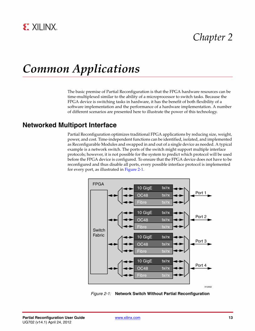
Networked Multiport Interface Partial Reconfiguration optimizes traditional FPGA applications by reducing size, weight, power, and cost. Time-independent functions can be identified, isolated, and implemented as Reconfigurable Modules and swapped in and out of a single device as needed. A typical example is a network switch. The ports of the switch might support multiple interface protocols; however, it is not possible for the system to predict which protocol will be used before the FPGA device is configured. To ensure that the FPGA device does not have to be reconfigured and thus disable all ports, every possible interface protocol is implemented for every port, as illustrated in Figure 2-1.X-Ref Target - Figure 2-1
Figure 2-1: Network Switch Without Partial Reconfiguration
OC48
10 GigE tx/rx
tx/rx
tx/rx
OC48
Fibre
10 GigE tx/rx
tx/rx
tx/rx
OC48
Fibre
10 GigE tx/rx
tx/rx
tx/rx
OC48
Fibre
FPGA
SwitchFabric
Port 1
Port 2
Port 3
Port 4
X12002
10 GigE tx/rx
tx/rx
tx/rx Fibre
14 www.xilinx.com Partial Reconfiguration User GuideUG702 (v14.1) April 24, 2012
Chapter 2: Common Applications
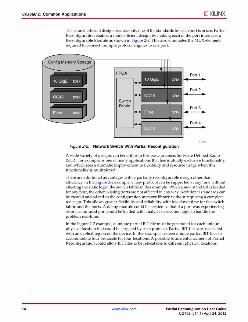
This is an inefficient design because only one of the standards for each port is in use. Partial Reconfiguration enables a more efficient design by making each of the port interfaces a Reconfigurable Module as shown in Figure 2-2. This also eliminates the MUX elements required to connect multiple protocol engines to one port.
A wide variety of designs can benefit from this basic premise. Software Defined Radio (SDR), for example, is one of many applications that has mutually exclusive functionality, and which sees a dramatic improvement in flexibility and resource usage when this functionality is multiplexed.
There are additional advantages with a partially reconfigurable design other than efficiency. In the Figure 2-2 example, a new protocol can be supported at any time without affecting the static logic, the switch fabric in this example. When a new standard is loaded for any port, the other existing ports are not affected in any way. Additional standards can be created and added to the configuration memory library without requiring a complete redesign. This allows greater flexibility and reliability with less down time for the switch fabric and the ports. A debug module could be created so that if a port was experiencing errors, an unused port could be loaded with analysis/correction logic to handle the problem real-time.
In the Figure 2-2 example, a unique partial BIT file must be generated for each unique physical location that could be targeted by each protocol. Partial BIT files are associated with an explicit region on the device. In this example, sixteen unique partial BIT files to accommodate four protocols for four locations. A possible future enhancement of Partial Reconfiguration could allow BIT files to be relocatable to different physical locations.
X-Ref Target - Figure 2-2
Figure 2-2: Network Switch With Partial Reconfiguration
Config Memory Storage
tx/rxFibre
tx/rxOC48
tx/rx10 GigE 10 GigE tx/rx
tx/rxOC48
tx/rxFibre
tx/rxOC48
SwitchFabric
FPGA Port 1
Port 2
Port 3
Port 4
X12003
Partial Reconfiguration User Guide www.xilinx.com 15UG702 (v14.1) April 24, 2012
Configuration by Means of PCIe Interface
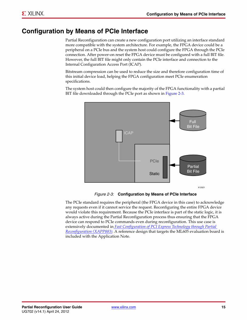
Configuration by Means of PCIe InterfacePartial Reconfiguration can create a new configuration port utilizing an interface standard more compatible with the system architecture. For example, the FPGA device could be a peripheral on a PCIe bus and the system host could configure the FPGA through the PCIe connection. After power-on reset the FPGA device must be configured with a full BIT file. However, the full BIT file might only contain the PCIe interface and connection to the Internal Configuration Access Port (ICAP).
Bitstream compression can be used to reduce the size and therefore configuration time of this initial device load, helping the FPGA configuration meet PCIe enumeration specifications.
The system host could then configure the majority of the FPGA functionality with a partial BIT file downloaded through the PCIe port as shown in Figure 2-3.
The PCIe standard requires the peripheral (the FPGA device in this case) to acknowledge any requests even if it cannot service the request. Reconfiguring the entire FPGA device would violate this requirement. Because the PCIe interface is part of the static logic, it is always active during the Partial Reconfiguration process thus ensuring that the FPGA device can respond to PCIe commands even during reconfiguration. This use case is extensively documented in Fast Configuration of PCI Express Technology through Partial Reconfiguration (XAPP883). A reference design that targets the ML605 evaluation board is included with the Application Note.
X-Ref Target - Figure 2-3
Figure 2-3: Configuration by Means of PCIe Interface
Full Bit File
ICAP
PCIe
Static
PartialBit File
X12021
16 www.xilinx.com Partial Reconfiguration User GuideUG702 (v14.1) April 24, 2012
Chapter 2: Common Applications
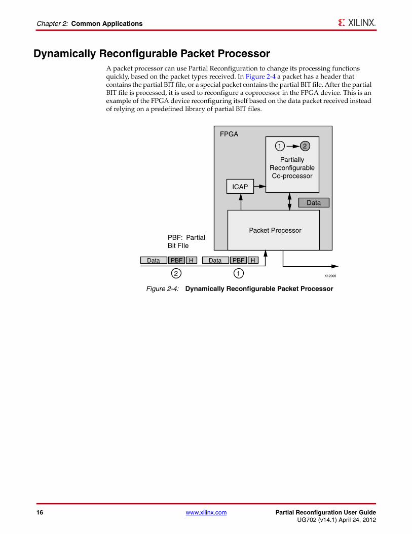
Dynamically Reconfigurable Packet Processor A packet processor can use Partial Reconfiguration to change its processing functions quickly, based on the packet types received. In Figure 2-4 a packet has a header that contains the partial BIT file, or a special packet contains the partial BIT file. After the partial BIT file is processed, it is used to reconfigure a coprocessor in the FPGA device. This is an example of the FPGA device reconfiguring itself based on the data packet received instead of relying on a predefined library of partial BIT files.X-Ref Target - Figure 2-4
Figure 2-4: Dynamically Reconfigurable Packet Processor
FPGA
Packet Processor
ICAP
Data
PartiallyReconfigurableCo-processor
1 2
2 1
PBF: PartialBit FIle
Data PBF H Data HPBF
X12005
Partial Reconfiguration User Guide www.xilinx.com 17UG702 (v14.1) April 24, 2012
Asymmetric Key Encryption
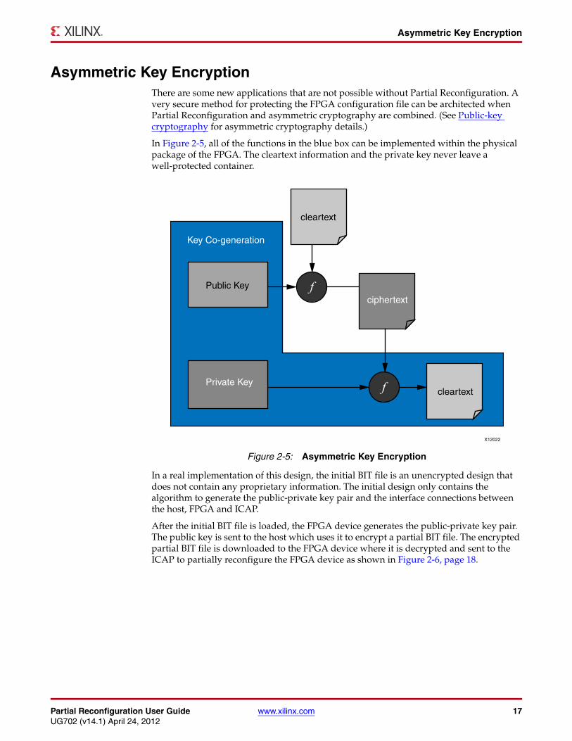
Asymmetric Key EncryptionThere are some new applications that are not possible without Partial Reconfiguration. A very secure method for protecting the FPGA configuration file can be architected when Partial Reconfiguration and asymmetric cryptography are combined. (See Public-key cryptography for asymmetric cryptography details.)
In Figure 2-5, all of the functions in the blue box can be implemented within the physical package of the FPGA. The cleartext information and the private key never leave a well-protected container.
In a real implementation of this design, the initial BIT file is an unencrypted design that does not contain any proprietary information. The initial design only contains the algorithm to generate the public-private key pair and the interface connections between the host, FPGA and ICAP.
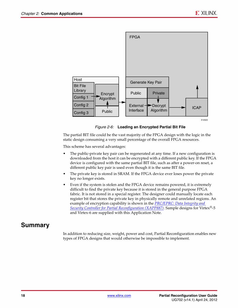
After the initial BIT file is loaded, the FPGA device generates the public-private key pair. The public key is sent to the host which uses it to encrypt a partial BIT file. The encrypted partial BIT file is downloaded to the FPGA device where it is decrypted and sent to the ICAP to partially reconfigure the FPGA device as shown in Figure 2-6, page 18.
X-Ref Target - Figure 2-5
Figure 2-5: Asymmetric Key Encryption
X12022
cleartext
cleartext
ciphertext
Public Key
Private Key
Key Co-generation
f
f
18 www.xilinx.com Partial Reconfiguration User GuideUG702 (v14.1) April 24, 2012
Chapter 2: Common Applications
The partial BIT file could be the vast majority of the FPGA design with the logic in the static design consuming a very small percentage of the overall FPGA resources.
This scheme has several advantages:
• The public-private key pair can be regenerated at any time. If a new configuration is downloaded from the host it can be encrypted with a different public key. If the FPGA device is configured with the same partial BIT file, such as after a power-on reset, a different public key pair is used even though it is the same BIT file.
• The private key is stored in SRAM. If the FPGA device ever loses power the private key no longer exists.
• Even if the system is stolen and the FPGA device remains powered, it is extremely difficult to find the private key because it is stored in the general purpose FPGA fabric. It is not stored in a special register. The designer could manually locate each register bit that stores the private key in physically remote and unrelated regions. An example of encryption capability is shown in the PRC/EPRC: Data Integrity and Security Controller for Partial Reconfiguration (XAPP887). Sample designs for Virtex®-5 and Virtex-6 are supplied with this Application Note.
SummaryIn addition to reducing size, weight, power and cost, Partial Reconfiguration enables new types of FPGA designs that would otherwise be impossible to implement.
X-Ref Target - Figure 2-6
Figure 2-6: Loading an Encrypted Partial Bit File
X12023
FPGA
Generate Key PairHost
Bit FileLibrary
Config 1Encrypt
Algorithm
Public
Config 2
Config 3
Public
ExternalInterface
DecryptAlgorithm
ICAP
Private
Partial Reconfiguration User Guide www.xilinx.com 19UG702 (v14.1) April 24, 2012
Chapter 3
Software Tools Flow
This chapter explains the underlying software tools flow, how to build a system that supports a partially reconfigurable FPGA and structure a partially reconfigurable design, and the application of constraints.
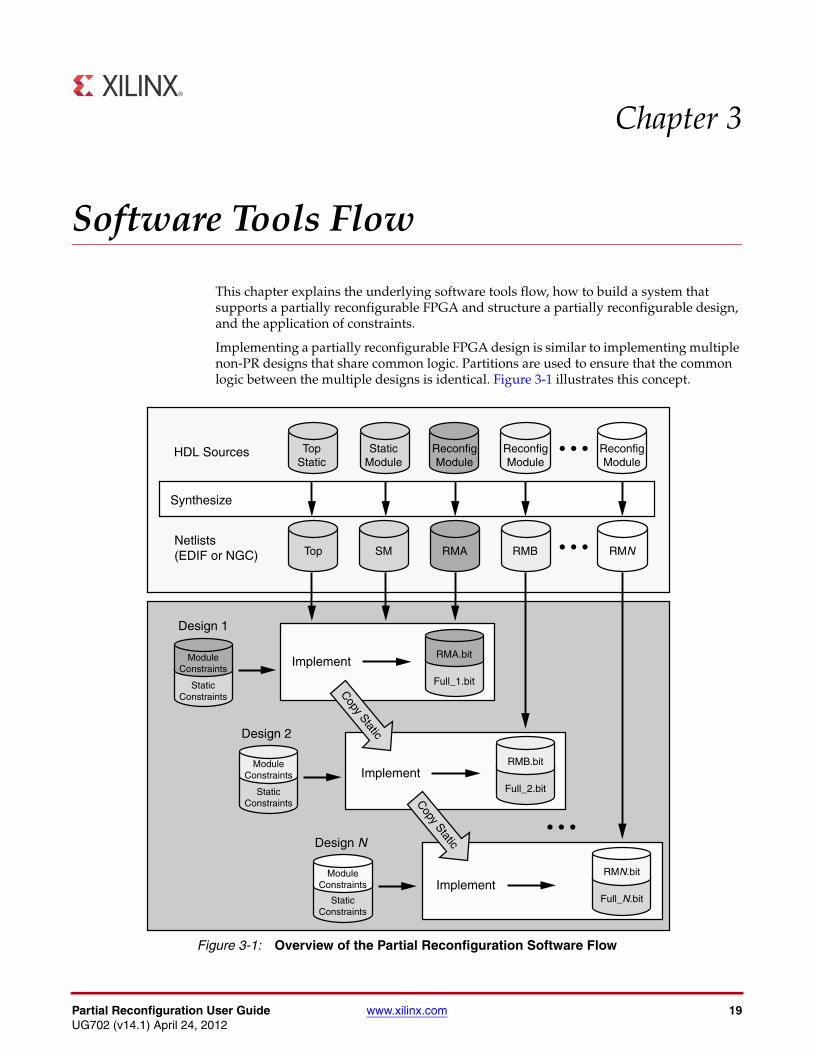
Implementing a partially reconfigurable FPGA design is similar to implementing multiple non-PR designs that share common logic. Partitions are used to ensure that the common logic between the multiple designs is identical. Figure 3-1 illustrates this concept.
X-Ref Target - Figure 3-1
Figure 3-1: Overview of the Partial Reconfiguration Software Flow
TopStatic
Top SM RMA RMB RMN
StaticModule
ReconfigModule
ReconfigModule
ReconfigModule
HDL Sources
Implement
Design 1
Design 2
Design N
Synthesize
Netlists(EDIF or NGC)
Implement
Implement
Copy Static
Copy Static
Full_1.bit
Full_2.bit
Full_N.bit
StaticConstraints
StaticConstraints
StaticConstraints
ModuleConstraints
ModuleConstraints
ModuleConstraints
RMN.bit
RMB.bit
RMA.bit
20 www.xilinx.com Partial Reconfiguration User GuideUG702 (v14.1) April 24, 2012
Chapter 3: Software Tools Flow
The top gray box represents the synthesis of HDL source to netlists for each module. The appropriate netlists are implemented in each design to generate the full and partial BIT files for that configuration. The static logic from the first implementation is shared among all subsequent design implementations.
Example Design Structure Throughout this guide, the Color2 sample design is used to illustrate design flow and techniques. This design displays on a DVI support monitor color bars of primary color red, blue, and non-primary green as well as the different shades of mixing the primary colors. The partial Reconfigurable Modules are the red, blue and green modules. The variants of each of the modules are fast and slow for each red, blue and green. The speed of the color represents how fast the LEDs are blinking on the demo board – this design targets the Virtex®-6 ML-605 Evaluation Platform.
Design files for the referenced design can be downloaded from:
http://www.xilinx.com/tools/partial-reconfiguration
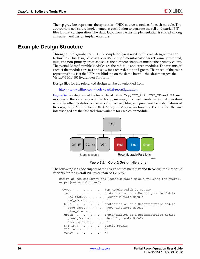
Figure 3-2 is a diagram of the hierarchical netlist. Top, IIC_init, DVI_IF, and VGA are modules in the static region of the design, meaning this logic maintains normal operation while the other modules can be reconfigured. red, blue, and green are the instantiations of Reconfigurable Module for the Red, Blue, and Green functionality. The modules that are interchanged are the fast and slow variants for each color module.
The following is a code snippet of the design source hierarchy and Reconfigurable Module variants for the overall PR Project named Color2:
Design source hierarchy and Reconfigurable Module variants for overall PR project named Color2: Top.v . . . . . . . . . top module which is static red. . . . . . . . . . instantiation of a Reconfigurable Module red_fast.v. . . . . . Reconfigurable Module red_slow.v. . . . . . "" blue . . . . . . . . . instantiation of a Reconfigurable Module blue_fast.v . . . . . Reconfigurable Module blue_slow.v . . . . . "" green. . . . . . . . . instantiation of a Reconfigurable Module green_fast.v. . . . . Reconfigurable Module green_slow.v. . . . . "" DVI_IF.v . . . . . . . static module IIC_init.v . . . . . . "" VGA.v. . . . . . . . . ""
X-Ref Target - Figure 3-2
Figure 3-2: Color2 Design HierarchyX12025
TOP
DVI_IF VGA Red Blue GreenICC_init
Static Modules Reconfigurable Partitions
Partial Reconfiguration User Guide www.xilinx.com 21UG702 (v14.1) April 24, 2012
Example Project File Structure
Red, Green, and Blue are partially reconfigurable instances. All other logic in the design is static.
The instances Red, Green, and Blue do not contain any logic, they are simply instantiation statements; the module definitions such as red_fast and blue_slow contain the logic to be implemented.
Example Project File StructureA partially reconfigurable FPGA design project is more complex than an average FPGA design project. A clearly defined file and directory structure eases the task of project management.
There are multiple Reconfigurable Modules for each Reconfigurable Partition in the overall project. The modules are synthesized in a bottom-up fashion, resulting in many netlists associated with each Reconfigurable Partition. The implementation is then done top-down, which defines a specific set of netlists, called a Configuration.
To eliminate confusion between sources, constraints, synthesis results, and implementation results, separate directories are recommended for each step in the design implementation. A commonly used (though not required) directory structure for a PR design is shown in the following file snippet.
project_name . . . . . name of the overall project Docs. . . . . . . . . user or design documents Implementation. . . . Xilinx software implementation results modules. . . . . . . static or Reconfig Module netlists configurations . . . Configuration implementation results Source. . . . . . . . source files modules. . . . . . . HDL source files for static and Reconfig Modules UCF. . . . . . . . . constraint files Synth . . . . . . . . synthesis results modules. . . . . . . netlists for each static and Reconfig Module Tools . . . . . . . . Tcl scripts or any other user scripts
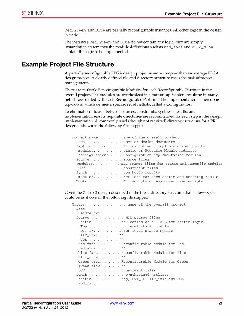
Given the Color2 design described in the file, a directory structure that is flow-based could be as shown in the following file snippet:
Color2. . . . . . . . . . name of the overall project Docs readme.txt Source . . . . . . . . HDL source files Static. . . . . . . collection of all HDL for static logic Top . . . . . . . top level static module DVI_IF. . . . . . lower level static module IIC_init. . . . . "" VGA . . . . . . . "" red_fast. . . . . . Reconfigurable Module for Red red_slow. . . . . . "" blue_fast . . . . . Reconfigurable Module for Blue blue_slow . . . . . "" green_fast. . . . . Reconfigurable Module for Green green_slow. . . . . "" UCF . . . . . . . . constraint files Synth. . . . . . . . . synthesized netlists static. . . . . . . top, DVI_IF, IIC_init and VGA red_fast
22 www.xilinx.com Partial Reconfiguration User GuideUG702 (v14.1) April 24, 2012
Chapter 3: Software Tools Flow
red_slow blue_fast blue_slow green_fast green_slow Implementation . . . . implementation results from scripted runs FastConfig. . . . . contains implementation results and BIT files SlowConfig. . . . . "" FSFConfig . . . . . "" BlankConfig . . . . contains black boxes for the three colors PlanAhead. . . . . . . implementation results from PlanAhead runs FFF . . . . . . . . contains implementation results and BIT files SSS . . . . . . . . "" FSF . . . . . . . . "" BB. . . . . . . . . contains black boxes for the three colors Tools. . . . . . . . . Tcl scripts or any other user scripts
SynthesisEach Reconfigurable Module is synthesized independently from the others in a bottom-up fashion. This can be done through the use of independent projects, either through a graphical interface or on the command line. For each module, be sure to disable I/O insertion, as the ports of these modules (in most cases) do not connect to package pins, but to the static logic above it.
The static modules can be synthesized together to generate one netlist or individually to generate multiple static netlists. The NGDBuild utility merges the static and reconfigurable modules, and the Reconfigurable Partition definitions denote the interfaces between the static and reconfigurable logic. Different options can be used for any of the static or reconfigurable module synthesis.
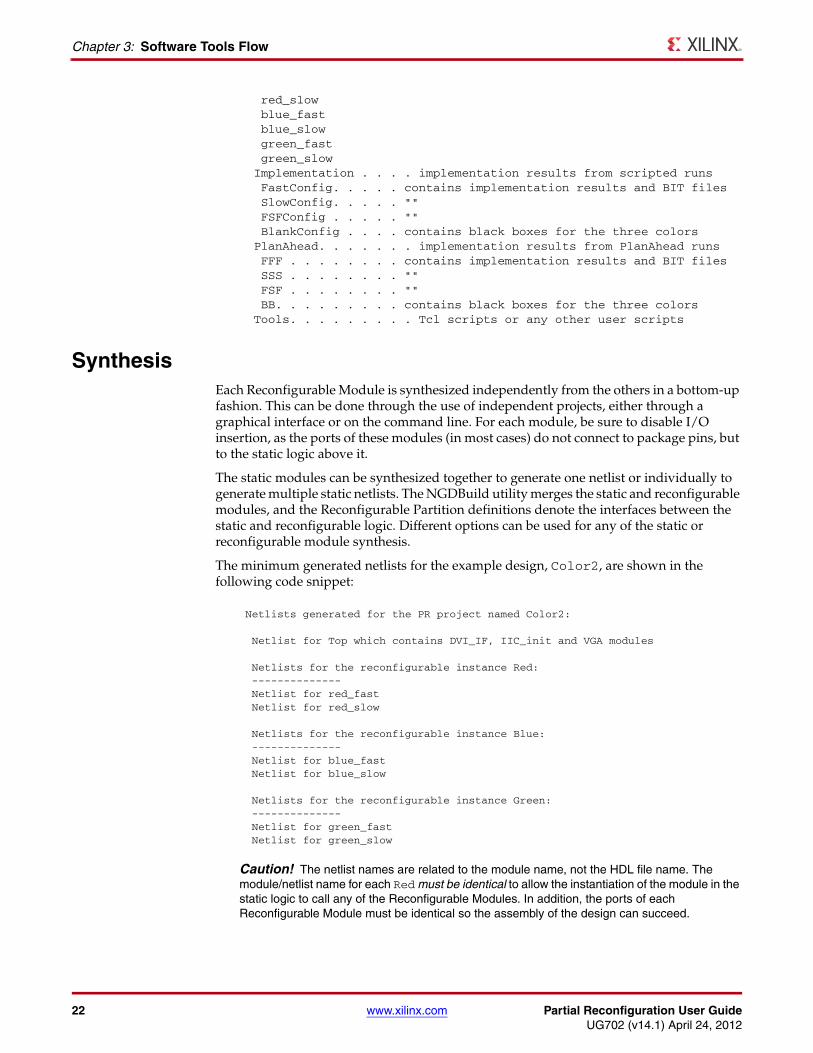
The minimum generated netlists for the example design, Color2, are shown in the following code snippet:
Caution! The netlist names are related to the module name, not the HDL file name. The module/netlist name for each Red must be identical to allow the instantiation of the module in the static logic to call any of the Reconfigurable Modules. In addition, the ports of each Reconfigurable Module must be identical so the assembly of the design can succeed.
Netlists generated for the PR project named Color2: Netlist for Top which contains DVI_IF, IIC_init and VGA modules
Netlists for the reconfigurable instance Red: -------------- Netlist for red_fast Netlist for red_slow
Netlists for the reconfigurable instance Blue: -------------- Netlist for blue_fast Netlist for blue_slow
Netlists for the reconfigurable instance Green: -------------- Netlist for green_fast Netlist for green_slow
Partial Reconfiguration User Guide www.xilinx.com 23UG702 (v14.1) April 24, 2012
Configurations
Each instantiation of a reconfigurable module must have a unique module name. In this sample design, Red can be instantiated only once. This allows the implementation tools to determine which Reconfigurable Modules are associated with which Reconfigurable Partition.
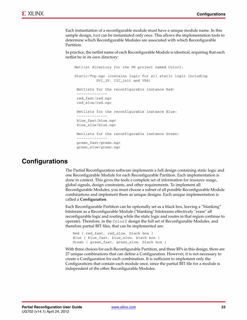
In practice, the netlist name of each Reconfigurable Module is identical, requiring that each netlist be in its own directory:
Configurations The Partial Reconfiguration software implements a full design containing static logic and one Reconfigurable Module for each Reconfigurable Partition. Each implementation is done in context. This gives the tools a complete set of information for resource usage, global signals, design constraints, and other requirements. To implement all Reconfigurable Modules, you must choose a subset of all possible Reconfigurable Module combinations and implement them as unique designs. Each unique implementation is called a Configuration.
Each Reconfigurable Partition can be optionally set as a black box, leaving a “blanking” bitstream as a Reconfigurable Module ("blanking" bitstreams effectively "erase" all reconfigurable logic and routing while the static logic and routes in that region continue to operate). Therefore, in the Color2 design the full set of Reconfigurable Modules, and therefore partial BIT files, that can be implemented are:
Red { red_fast, red_slow, black box }Blue { blue_fast, blue_slow, black box }Green { green_fast, green_slow, black box }
With three choices for each Reconfigurable Partition, and three RPs in this design, there are 27 unique combinations that can define a Configuration. However, it is not necessary to create a Configuration for each combination. It is sufficient to implement only the Configurations that contain each module once, since the partial BIT file for a module is independent of the other Reconfigurable Modules.
Netlist directory for the PR project named Color2: Static/Top.ngc (contains logic for all static logic including DVI_IF, IIC_init and VGA) Netlists for the reconfigurable instance Red: -------------- red_fast/red.ngc red_slow/red.ngc Netlists for the reconfigurable instance Blue: -------------- blue_fast/blue.ngc blue_slow/blue.ngc
Netlists for the reconfigurable instance Green: -------------- green_fast/green.ngc green_slow/green.ngc
24 www.xilinx.com Partial Reconfiguration User GuideUG702 (v14.1) April 24, 2012
Chapter 3: Software Tools Flow
In the Color2 design, one minimal set is as shown in the following snippet:
Minimum number of FPGA designs (Configurations) required to implement the PR project Color2: First Configuration Second Configuration Third Configuration------------------- -------------------- ------------------- Top Top Top Red Red Red red_fast red_slow black box Blue Blue Blue blue_fast blue_slow black box Green Green Green green_fast green_slow black box DVI_IF DVI_IF DVI_IF IIC_init IIC_init IIC_init VGA VGA VGA
There are three different modules each for Red, Green, and Blue. Accordingly, a minimum of just three Configurations is necessary to implement all Reconfigurable Modules. If desired, further Configurations can be created to achieve unique full BIT files.
For example, a Fourth Configuration containing modules red_fast, blue_slow, and green_fast can be created. All three Reconfigurable Modules are re-used in this Configuration. The implementation results and partial BIT files for these modules are identical between the multiple Configurations.
Once a partial bitstream is created, it can be loaded in the FPGA device in any combination of full or partial bitstreams created within that PR project; however, to validate that a particular combination works as expected, it might be necessary to create a Configuration for that combination of modules. Full design-level simulation and verification flows for Partial Reconfiguration designs are no different than for standard designs.
ConstraintsConstraints for the static logic are usually stored in the UCF file and are shared among all Configurations. By using the ngdbuild -uc option, one common UCF file can be shared among all Configurations to ensure that all static constraints are identical.
There may be module specific constraints that cannot be included in the static logic constraints. For example, if a timing constraint is set on a path that only exists in red_fast then the constraint can only be applied to the First Configuration above. This can be accomplished by using the PlanAhead™ software to manage the constraint files, or by embedding the constraint within the specific module netlist. The ngdbuild -uc switch can be used multiple times per command line invocation, so more than one UCF can be specified per run.
Area Group ConstraintsAn AREA_GROUP is a grouping constraint that associates logical design elements with a particular label or group. AREA_GROUP constraints and Partition definitions are necessary to delineate the static (non-reconfigurable) logic from the reconfigurable logic, preventing logic in the static design from merging with logic in the RMs, and vice versa. The AREA_GROUP constraints must be defined for each Reconfigurable Partition. The following example shows an AREA_GROUP constraint called pblock_reconfig_red for a Reconfigurable Partition named reconfig_red:
INST “reconfig_red” AREA_GROUP = “pblock_reconfig_red”;
Partial Reconfiguration User Guide www.xilinx.com 25UG702 (v14.1) April 24, 2012
Constraints
At least one and possibly more AREA_GROUP RANGE constraints must be defined for each reconfigurable region to set the shape and placement of the PR region. The primary range constraint is usually a Slice range that defines which Slices are part of the PR region. The Slice contains the basic LUT and FF logical elements. If the RMs also contain block RAM or other types of logical components, then additional range constraints must be created for them.
There are a few requirements when setting AREA_GROUP RANGE constraints, and PlanAhead will help manage many of these aspects:
• AREA_GROUP RANGE constraints are required for each Reconfigurable Partition, as they define the size and shape of those regions.
• All device resources (such as Slices, block RAM, and DSP blocks) that are part of any Reconfigurable Module that are placed in that Reconfigurable Partition must each have corresponding AREA_GROUP RANGE constraints. Even single-site resources must have an associated RANGE constraint.
• Do NOT create AREA_GROUP RANGE constraints for elements that should not be (or are not allowed to be) reconfigured. For example, do not create AREA_GROUP RANGE constraints for DCM, PLL, or BUFG elements.
• If a single Reconfigurable Partition is defined by multiple AREA_GROUP RANGE constraints, they must be contiguous.
• The AREA_GROUP RANGE constraints of a given Reconfigurable Partition must not overlap the AREA_GROUP RANGE constraints of any other Reconfigurable Partition. Moreover, no two Reconfigurable Partitions may occupy the same reconfigurable frame.
• PR Slice regions should be defined from the lower left corner (minX, minY) to the upper right corner (maxX, maxY). For example:
INST “reconfig_red” AREA_GROUP = “pblock_reconfig_red”;AREA_GROUP “pblock_reconfig_red” RANGE = SLICE_X20Y76:SLICE_X25Y79;
INST “reconfig_blue” AREA_GROUP = “pblock_reconfig_blue”;AREA_GROUP “pblock_reconfig_blue” RANGE = SLICE_X28Y64:SLICE_X33Y67;
INST “reconfig_green” AREA_GROUP = “pblock_reconfig_green”;AREA_GROUP “pblock_reconfig_green” RANGE = SLICE_X20Y50:SLICE_X25Y53;
• Some logic types can be in a Reconfigurable Partition and some cannot. Slices, Block RAM, and DSP48 logic can be in an RP. Global clocking logic, including clock modifying logic like the DCM, PLL, or PMCD, I/O and related components, and MGTs and MGT-related components must be in a static module. For more information on Reconfigurable Partition regulations, see Chapter 7, Design Considerations.
• The Slice range must be on a CLB boundary (not split a CLB). Following this rule ensures that any AREA_GROUP RANGE constraint fully encapsulates CLBs for Virtex-5 devices:
• AREA_GROUP Slice range horizontal coordinates (minX) is always EVEN.
• AREA_GROUP Slice range horizontal coordinates (maxX) is always ODD.
This rule ensures that a Reconfigurable Partition's RANGE falls on CLB boundaries in a Virtex-5 device. It does not ensure that any reconfigurable frame rules are followed. Be sure to follow the frame rules described in Chapter 7, Design Considerations
• The AREA_GROUP RANGE for block RAM has coordinates (minX, minY) and (maxX, maxY) which can be either odd or even. The AREA_GROUP block RAM range can be determined by looking in PlanAhead or the FPGA Editor.
26 www.xilinx.com Partial Reconfiguration User GuideUG702 (v14.1) April 24, 2012
Chapter 3: Software Tools Flow
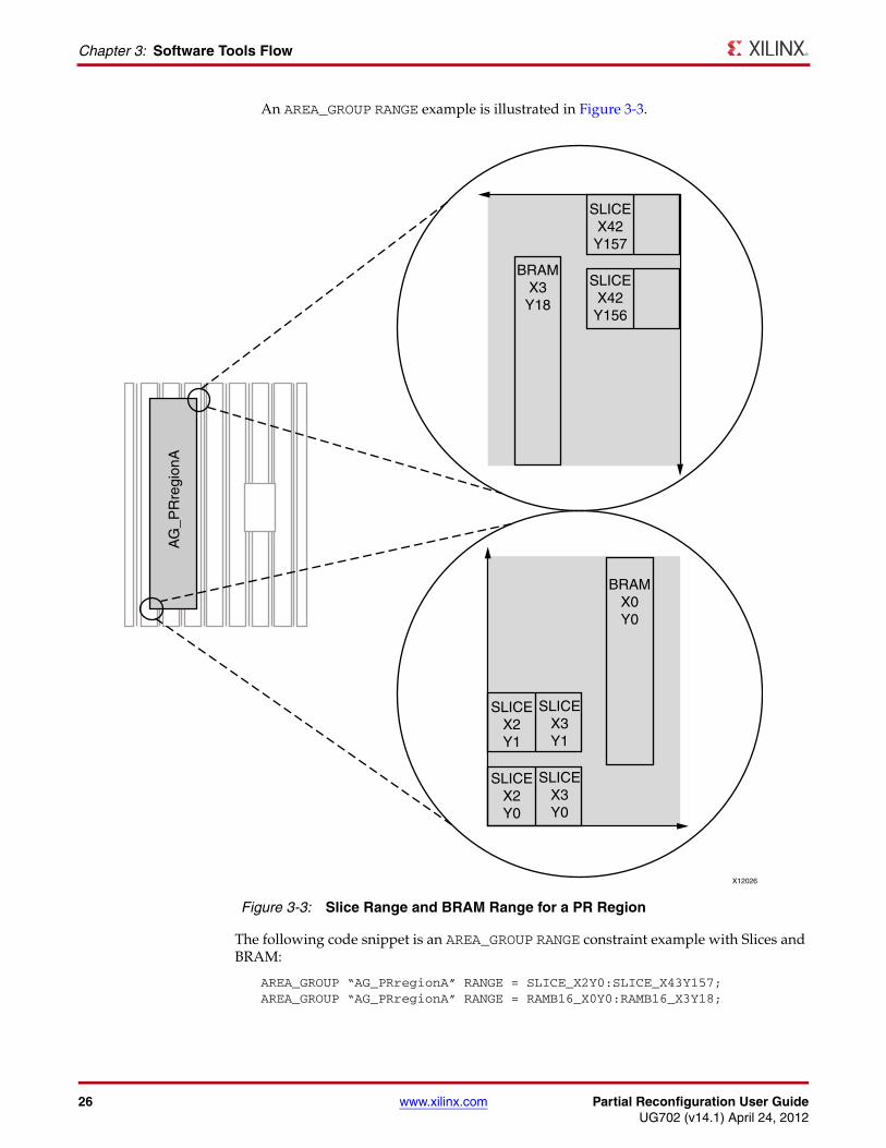
An AREA_GROUP RANGE example is illustrated in Figure 3-3.
The following code snippet is an AREA_GROUP RANGE constraint example with Slices and BRAM:
AREA_GROUP “AG_PRregionA” RANGE = SLICE_X2Y0:SLICE_X43Y157;AREA_GROUP “AG_PRregionA” RANGE = RAMB16_X0Y0:RAMB16_X3Y18;
X-Ref Target - Figure 3-3
Figure 3-3: Slice Range and BRAM Range for a PR Region
X12026
BRAMX0Y0
BRAMX3Y18
SLICEX42
Y157
SLICEX42
Y156
SLICEX2Y1
SLICEX3Y1
SLICEX2Y0
SLICEX3Y0
AG
_PR
regi
onA
Partial Reconfiguration User Guide www.xilinx.com 27UG702 (v14.1) April 24, 2012
Constraints
The PlanAhead software estimates the size of each RM and displays the resources used, which is useful in determining if an AREA_GROUP RANGE is necessary for Block RAM or I/O.
However, the tools cannot make recommendations as to the shape or placement of the Reconfigurable Partition. The AREA_GROUP RANGE must be large enough to accommodate the largest RM for each resource type (that is, the RM using the most Slices might not be the RM using the most BRAM), and it must be shaped and placed in a way that allows the design to meet timing.
Partition PinsPR designs contain special components named Partition Pins at the port boundary between static logic and reconfigurable logic. Partition Pins are necessary to guarantee that the circuit connections between the static logic and the different RMs for each RP are identical. The Partition Pin is also a convenient component for creating timing constraints on nets that pass to, from, or through the RP boundary.
Partition Pins are inserted automatically by the implementation software. No special instantiations or other considerations are required of the designer, with the exception of controlled routes, which is described in Chapter 7, Design Considerations.
Note: Partition Pins can be input or output connections to a reconfigurable region. Partition Pins cannot be bidirectional.
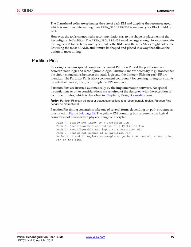
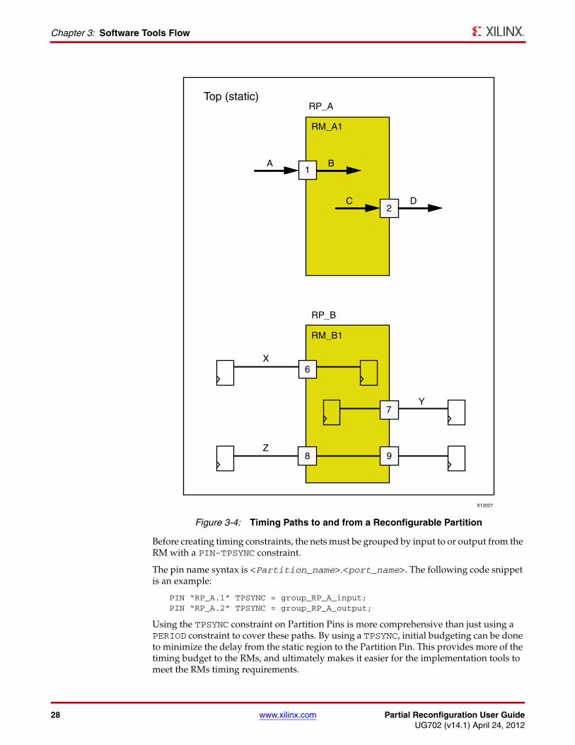
Partition Pin timing constraints take one of several forms depending on path structure as illustrated in Figure 3-4, page 28. The yellow RM bounding box represents the logical boundary, not necessarily a physical range or floorplan.
Path A) Static net input to a Partition PinPath B) Reconfigurable net output of a Partition PinPath C) Reconfigurable net input to a Partition PinPath D) Static net output of a Partition PinPaths X, Y and Z) Register-to-register paths that contain a Partition Pin in the path
28 www.xilinx.com Partial Reconfiguration User GuideUG702 (v14.1) April 24, 2012
Chapter 3: Software Tools Flow
Before creating timing constraints, the nets must be grouped by input to or output from the RM with a PIN-TPSYNC constraint.
The pin name syntax is <Partition_name>.<port_name>. The following code snippet is an example:
PIN “RP_A.1” TPSYNC = group_RP_A_input;PIN “RP_A.2” TPSYNC = group_RP_A_output;
Using the TPSYNC constraint on Partition Pins is more comprehensive than just using a PERIOD constraint to cover these paths. By using a TPSYNC, initial budgeting can be done to minimize the delay from the static region to the Partition Pin. This provides more of the timing budget to the RMs, and ultimately makes it easier for the implementation tools to meet the RMs timing requirements.
X-Ref Target - Figure 3-4
Figure 3-4: Timing Paths to and from a Reconfigurable Partition
X12027
Top (static)RP_A
RP_B
RM_A1
RM_B1
X
A B
C D
6
1
2
7
8 9
Y
Z
Partial Reconfiguration User Guide www.xilinx.com 29UG702 (v14.1) April 24, 2012
Constraints
The PIN-TPSYNC grouping constraint supports standard UCF wildcard conventions. For example, if there was a data bus input to RP_A it could be added to the input group in the previous example with this constraint:
PIN “RP_A.data*” TPSYNC = group_RP_A_input;
To create timing constraints for all static nets going to Partition Pin RP_A.1 and all reconfigurable nets going from Partition Pin RP_A.1 (paths A & B above), use this convention:
TIMESPEC TS_from_static_to_PP_input = TO “group_RP_A_input” 4.5 ns;TIMESPEC TS_from_PP_input_to_RM = FROM “group_RP_A_input” 4.5 ns;
To create timing constraints for all reconfigurable nets going to Partition Pin RP_A.2 and all static nets going from Partition Pin RP_A.2 (paths C & D above) use this convention:
TIMESPEC TS_from_RM_to_PP_output = TO “group_RP_A_output” 4.5 ns;TIMESPEC TS_from_PP_output_to_static = FROM “group_RP_A_output” 4.5 ns;
Because these constraints might cover asynchronous paths, Xilinx® recommends that all paths to and from Reconfigurable Partitions be synchronous.
During an initial implementation, only one of the RMs is considered for timing purposes. The tool-generated timing budget might not provide enough timing margin for all of the other RMs to meet timing when they are implemented later. The TPSYNC option allows you to constrain the static portion of the design separately from each RM. This helps ensure that an adequate timing budget is allocated to the static region and to each RM.
For more information on a TPSYNC limitation, see Appendix A, Known Issues and Known Limitations.
A standard period timing constraint is used for register-to-register paths that contain Partition Pins. Nets X, Y & Z above would be constrained by the following:
NET clk TNM_NET = clk_group;TIMESPEC TS_clk_period = PERIOD clk_group 10 ns;
This constraint ensures that the register-to-register path, including Partition Pin delay, meets the timing constraint. It does not specify what portion of the net delay is allocated to static and reconfigurable parts of the net. Therefore, the PERIOD constraint should be used in combination with FROM, TO, and FROM:TO constraints to accurately budget the entire path.
Connecting input pads directly into a Partition, or outputs from a Partition directly to an output pad, could result in suboptimal timing performance. The Partition Pins are made of combinatorial logic and add path delay. The Partition Pins also prevent IOB packing which could lead to timing failures for the inputs and outputs if that packing were required.
Xilinx® strongly recommends that all signals, except global clocks, passing through the Reconfigurable Partition boundary are registered to simplify timing constraints and to increase the likelihood that timing constraints are met. However, if pads are connected directly to a synchronous component in a Reconfigurable Partition, then OFFSET constraints can be used to correctly constrain the path.
If an input pad drives a synchronous component inside of a Partition, an OFFSET IN constraint can be applied to constrain the input. This correctly takes the Partition Pin delay into account. A global OFFSET IN that could apply:
OFFSET = IN 3 ns VALID 8 ns BEFORE “clk”;
If a synchronous component drives the output of a Partition and the Partition output drives an output pad, an OFFSET OUT constraint can be applied to constrain that output.
30 www.xilinx.com Partial Reconfiguration User GuideUG702 (v14.1) April 24, 2012
Chapter 3: Software Tools Flow
This correctly takes the Partition Pin delay into account. A global OFFSET OUT that could apply:
OFFSET = OUT 5 ns AFTER “clk”;
Optionally, a Partition Pin can be physically locked to a site within the area_group range of the RP. This is not required, as they are placed automatically by the PR software, but can be done to gain an additional level of control in the implementation results. This methodology should be used as a last resort, and only after automatic placement, with timing constraints, has been explored. The following UCF command physically locks the Partition Pin to a site:
PIN “RP_A.1” LOC = SLICE_X4Y4;
Timing Constraints for the ICAPIf the Internal Configuration Access Port (ICAP) is used as the configuration port for partially reconfiguring the FPGA, timing constraints can be very useful to understand the potential performance of this interface.
7 Series and Virtex-6 ICAP Timing Constraints
In 7 series and Virtex-6 FPGAs, the ICAP is modeled as a synchronous component in TRACE. This means that PERIOD, FROM:TO, and all group based constraints will correctly cover paths to and from the ICAP site. No additional constraints are required, as long as the ICAP component is added to the applicable time groups.
Virtex-5 and Virtex-4 ICAP Timing Constraints
For Virtex-5 and Virtex-4 FPGAs, it is important to understand that the paths to the ICAP and from the ICAP are not covered by PERIOD constraints. The ICAP inputs and outputs are not considered synchronous by TRACE. This is also true for the BUSY, CE, and WRITE signals. This means that the inputs to and the outputs from the ICAP must be constrained using the exception constraint: NET MAXDELAY.
Using NET MAXDELAY constraints, the syntax looks like this:
NET “to_icap<*>” MAXDELAY = 15 ns;NET “from_icap<*>” MAXDELAY = 15 ns;NET “busy_from_icap” MAXDELAY = 15 ns;NET “write_to_icap” MAXDELAY = 15 ns;NET “ce_to_icap” MAXDELAY = 15 ns;
In this example, the to_icap and from_icap networks are buses of any width. The asterisk represents the entire bus (that is, 0, 1, 2, …). The NET MAXDELAY constraint constrains only the net delay. It does not take the setup time or clock-to-out time into consideration.
The ICAP component cannot be added to time groups because it is not considered a synchronous element. Therefore, the ICAP cannot be made a synchronous component by use of a TPSYNC constraint. The ICAP component is a special type of component and must given special consideration for timing when it is used in a design.
Partial Reconfiguration User Guide www.xilinx.com 31UG702 (v14.1) April 24, 2012
Constraints
Extracting Partition Pin informationPartition Pins are added by the implementation tools and do not exist in the logical source design. Partition Pins are named in a predictable fashion but to be absolutely sure that the correct names are used, the design must be run through implementation. The Partition Pin placement can then be extracted from an implemented design using the pr2ucf utility. Run the utility on the placed and routed NCD file within the Configuration directory:
pr2ucf design_routed.ncd –o partition_pins.ucf
The PIN location constraints can be back-annotated to the design UCF file by copying them from the partition_pins.ucf file to the design.ucf file, though this is not necessary to maintain placement from one Configuration to the next.
Even though Partition Pins are physically located within the reconfigurable regions, they are logically part of the static logic, and any constraints placed upon them must reside in the top-level UCF. Partition Pins can be viewed within FPGA Editor to see their placement in relation to other logic in the design.
Constraints EditorThe Constraints Editor can be used to create the Partition Pin groups and timing constraints after an initial implementation has been run on at least one Configuration.
When prompted for design files, select any NGD file in an up-to-date Configuration; however, the UCF must be a new file (created before the Constraints Editor is opened), not the name of the UCF file that has already been imported into the PlanAhead software or one that currently exists with a Configuration.
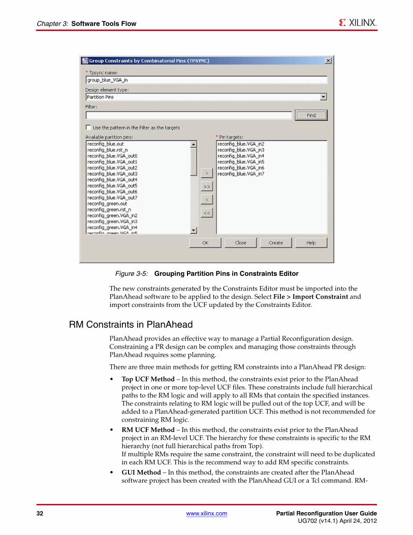
Within the Constraints Editor, there is a Group Constraints category in the Constraint Type window. Select By Combinatorial Pins to create TPSYNC constraints based on Partition Pins. In the dialog that opens, the Design element type field can be set to Partition Pins to find the instances easily within the design. Use groups created here to define timing specifications. Figure 3-5 shows the Group Constraints by Combinatorial Pins dialog box.
32 www.xilinx.com Partial Reconfiguration User GuideUG702 (v14.1) April 24, 2012
Chapter 3: Software Tools Flow
The new constraints generated by the Constraints Editor must be imported into the PlanAhead software to be applied to the design. Select File > Import Constraint and import constraints from the UCF updated by the Constraints Editor.
RM Constraints in PlanAheadPlanAhead provides an effective way to manage a Partial Reconfiguration design. Constraining a PR design can be complex and managing those constraints through PlanAhead requires some planning.
There are three main methods for getting RM constraints into a PlanAhead PR design:
• Top UCF Method – In this method, the constraints exist prior to the PlanAhead project in one or more top-level UCF files. These constraints include full hierarchical paths to the RM logic and will apply to all RMs that contain the specified instances. The constraints relating to RM logic will be pulled out of the top UCF, and will be added to a PlanAhead-generated partition UCF. This method is not recommended for constraining RM logic.
• RM UCF Method – In this method, the constraints exist prior to the PlanAhead project in an RM-level UCF. The hierarchy for these constraints is specific to the RM hierarchy (not full hierarchical paths from Top). If multiple RMs require the same constraint, the constraint will need to be duplicated in each RM UCF. This is the recommend way to add RM specific constraints.
• GUI Method – In this method, the constraints are created after the PlanAhead software project has been created with the PlanAhead GUI or a Tcl command. RM-
X-Ref Target - Figure 3-5
Figure 3-5: Grouping Partition Pins in Constraints Editor
Partial Reconfiguration User Guide www.xilinx.com 33UG702 (v14.1) April 24, 2012
Partitions and Import
specific constraints will only apply to the RM active at the time the constraints were created, and will be added to PlanAhead Generated RM UCF (they will not show up in the top-level target UCF). Instead, it is recommend to manually add these constraints to each user defined RM UCF, and then update the RM using the Update Reconfigurable Module command.
PlanAhead UCF Recommendations
There are rules regarding UCF constraints that should be followed when using the PlanAhead flow. Note that these rules will likely change as the constraint management system is modified in future releases of PlanAhead. However, for the 13.4 ISE® software, these rules should be followed:
• Use the Copy into Project option when specifying UCFs for a PlanAhead project. PlanAhead does some manipulation of RM constraints that are read into the tools. Following this rule will ensure that any changes done by PlanAhead only affect a local copy of the UCF.
• Put all RM constraints into RM-specific UCF files. Putting RM constraints into the top- level UCF or using the GUI to create RM UCFs can lead to undesirable behavior.
PlanAhead UCF Known Issues
• If the top-level UCF contains RM specific constraints, they will not be loaded properly until the RMs have been defined for appropriate RPs. If this occurs, the Netlist Design must be closed and reopened after the RM netlists have been added. This is a known issue that will be fixed in a future release, but can be avoided by following the recommendations above.
• The Netlist Design view should be opened for before launching a run. This will ensure that all constraints are properly applied to RM logic before the run files are written.
• If you make changes to constraints in the PlanAhead GUI, save the project, and then close and reopen the Netlist Design view before launching a run.
Partitions and Import Partitions guarantee that shared modules such as static logic are identical among all Configurations. A Partition is an attribute set on an instance (or top level module) which directs the Xilinx software to implement the logic in a particular way. The Partition itself has attributes such as RECONFIGURABLE and STATE that further direct the Xilinx software regarding how the Partition logic should be implemented.
The RECONFIGURABLE attribute determines whether the instance or module is implemented in a way that ultimately results in a partial BIT file. Because a reconfigurable module has many physical requirements that are not necessary for a non-reconfigurable module, the RECONFIGURABLE attribute must be set prior to running the implementation tool flow. This has a significant impact on the final implementation of the module.
The STATE attribute determines whether the module is implemented or imported (preserved) from a previously implemented design.
If the Partition is imported, then its implementation, including placement and routing, is identical to the design from which it was imported. For example, the first Configuration implements the static logic, and the user exports (promotes) this result. All subsequent implementations import the static Partition from the promoted Configuration. If the static logic is modified and re-exported, then the subsequent Configurations must be updated by importing the new static logic and re-implementing those Configurations.
34 www.xilinx.com Partial Reconfiguration User GuideUG702 (v14.1) April 24, 2012
Chapter 3: Software Tools Flow
Implementation tools use prior results to import Partition information. PlanAhead manages promoted Configuration data automatically, and command line users can manage this easily themselves. Simply copy the Configuration to a safe location to prevent these files from being overwritten when iterations on that Configuration are done. When importing from this Configuration, set the ImportLocation in the xpartition.pxml file to this directory. The important files in this directory include the xpartition.pxml and all of the *_prev_* files. In a PlanAhead project, these files are named <design>_prev_built.ngd, <design>_prev_mapped.ncd, <design>_prev_mapped.ngm, and <design>_routed_prev_routed.ncd. PlanAhead also keeps the report files for each step, to help document the Configuration that has been saved.
The Role of PXML FilesThe Partition information is stored in the xpartition.pxml file located in the implementation directory. Each Configuration has its own PXML file stored in its design directory.
The xpartition.pxml file:
• Is a text file using XML format
• Is generated automatically by the PlanAhead software or the provided gen_xp.tcl script. For more information on gen_xp.tcl see Chapter 5, Command Line Scripting.
• Can be user-created or modified
• Is treated by the implementation tools (such as MAP and PAR) as an input
• Can be considered a source for revision control needs
Xilinx software such as NGDBuild, MAP, and PAR looks automatically for and uses the xpartition.pxml file in the implementation directory. The XML file with the Partition information must be named xpartition.pxmland must reside in the implementation directory. Otherwise, the Reconfigurable Partitions are not recognized.
When the xpartition.pxml file is modified, portions of the flow must be rerun. If the STATE attribute is changed, then MAP or PAR can be re-run. If you re-run both MAP and PAR, placement and routing takes the STATE from the xpartition.pxml file. If you re-run just PAR, placement keeps the STATE from the previous run and the routing takes the STATE from the current xpartition.pxml. If the ImportLocation or Reconfigurable attributes are changed, NGDBuild, MAP, and PAR must all be re-run.
Note: The BoundaryOpt attribute, which is attached to a partition in a PXML file, cannot be used in a Partial Reconfiguration flow.
The following subsections show first, second, and third Configuration PXML files.
Partial Reconfiguration User Guide www.xilinx.com 35UG702 (v14.1) April 24, 2012
Partitions and Import
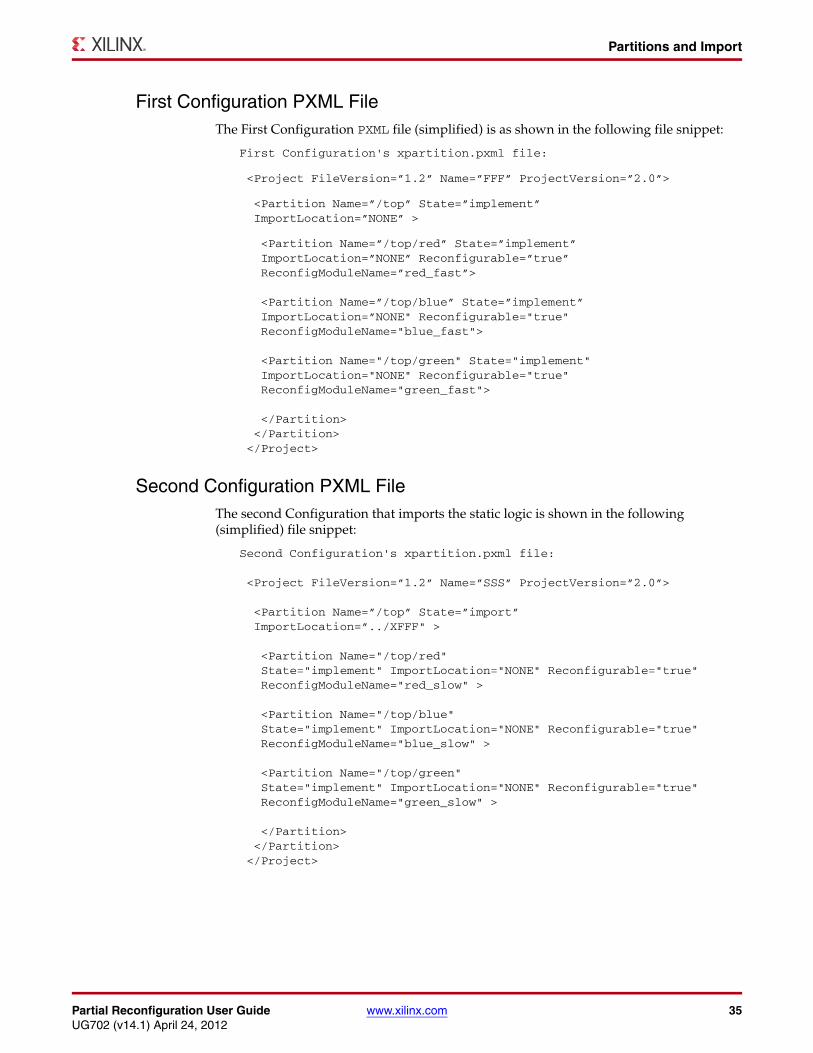
First Configuration PXML File The First Configuration PXML file (simplified) is as shown in the following file snippet:
First Configuration's xpartition.pxml file: <Project FileVersion=”1.2” Name=”FFF” ProjectVersion=”2.0”> <Partition Name=”/top” State=”implement” ImportLocation=”NONE” > <Partition Name=”/top/red” State=”implement” ImportLocation=”NONE” Reconfigurable=”true” ReconfigModuleName=”red_fast”>
<Partition Name=”/top/blue” State=”implement” ImportLocation=”NONE" Reconfigurable="true" ReconfigModuleName="blue_fast">
<Partition Name="/top/green" State="implement" ImportLocation="NONE" Reconfigurable="true" ReconfigModuleName="green_fast"> </Partition> </Partition> </Project>
Second Configuration PXML File The second Configuration that imports the static logic is shown in the following (simplified) file snippet:
Second Configuration's xpartition.pxml file: <Project FileVersion=”1.2” Name=”SSS” ProjectVersion=”2.0”> <Partition Name=”/top” State=”import” ImportLocation=”../XFFF" > <Partition Name="/top/red" State="implement" ImportLocation="NONE" Reconfigurable="true" ReconfigModuleName="red_slow" > <Partition Name="/top/blue" State="implement" ImportLocation="NONE" Reconfigurable="true" ReconfigModuleName="blue_slow" >
<Partition Name="/top/green" State="implement" ImportLocation="NONE" Reconfigurable="true" ReconfigModuleName="green_slow" > </Partition> </Partition> </Project>
36 www.xilinx.com Partial Reconfiguration User GuideUG702 (v14.1) April 24, 2012
Chapter 3: Software Tools Flow
Third Configuration PXML File The third Configuration which imports both static and all three Reconfigurable Modules is shown in the following (simplified) file snippet:
Third Configuration's xpartition.pxml file: <Project FileVersion="1.2“ Name=”FSF" ProjectVersion="2.0"> <Partition Name="/top" State="import" ImportLocation="../XFFF" > <Partition Name="/top/red" State="import" ImportLocation="../XFFF" Reconfigurable="true" ReconfigModuleName="red_fast" >
<Partition Name="/top/blue" State="import" ImportLocation="../XSSS" Reconfigurable="true" ReconfigModuleName="blue_slow" >
<Partition Name="/top/green" State="import" ImportLocation="../XFFF" Reconfigurable="true" ReconfigModuleName="green_fast" > </Partition> </Partition> </Project>
The static logic, along with the Red and Green modules, is imported from the first configuration. The Blue module is imported from the second Configuration.
ImplementationTo implement the FPGA design, run NGDBuild, MAP, and PAR in a similar fashion to a non-PR design. Most of the PR-specific information is contained in the xpartition.pxmlfile and the UCF file. There are no PR-specific command line switches. The following example shows the commands to implement a PR design:
ngdbuild -sd ../red_fast -sd ../blue_fast –sd ../green_fast -uc ../UCF/design.ucf ../Static/top.edf FFF.ngdmap -w -o FFF_map.ncd FFF.ngd FFF.pcfpar -w FFF_map.ncd FFF.ncd FFF.pcf
Not all Implementation options are available for Partial Reconfiguration. Options not available are:
• The -global_opt option to the MAP command and its child options
• The high and xe values for the -power option to the MAP command
• The BoundaryOpt attribute, which is applied to a partition in a PXML file
• SmartGuide™
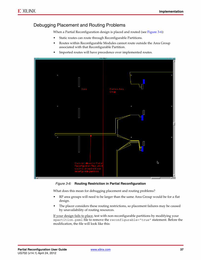
Partial Reconfiguration User Guide www.xilinx.com 37UG702 (v14.1) April 24, 2012
Implementation
Debugging Placement and Routing ProblemsWhen a Partial Reconfiguration design is placed and routed (see Figure 3-6):
• Static routes can route through Reconfigurable Partitions.
• Routes within Reconfigurable Modules cannot route outside the Area Group associated with that Reconfigurable Partition.
• Imported routes will have precedence over implemented routes.
What does this mean for debugging placement and routing problems?
• RP area groups will need to be larger than the same Area Group would be for a flat design.
• The placer considers these routing restrictions, so placement failures may be caused by unavailability of routing resources.
If your design fails to place, test with non-reconfigurable partitions by modifying your xpartition.pxml file to remove the reconfigurable=”true” statement. Before the modification, the file will look like this:
X-Ref Target - Figure 3-6
Figure 3-6: Routing Restriction in Partial Reconfiguration
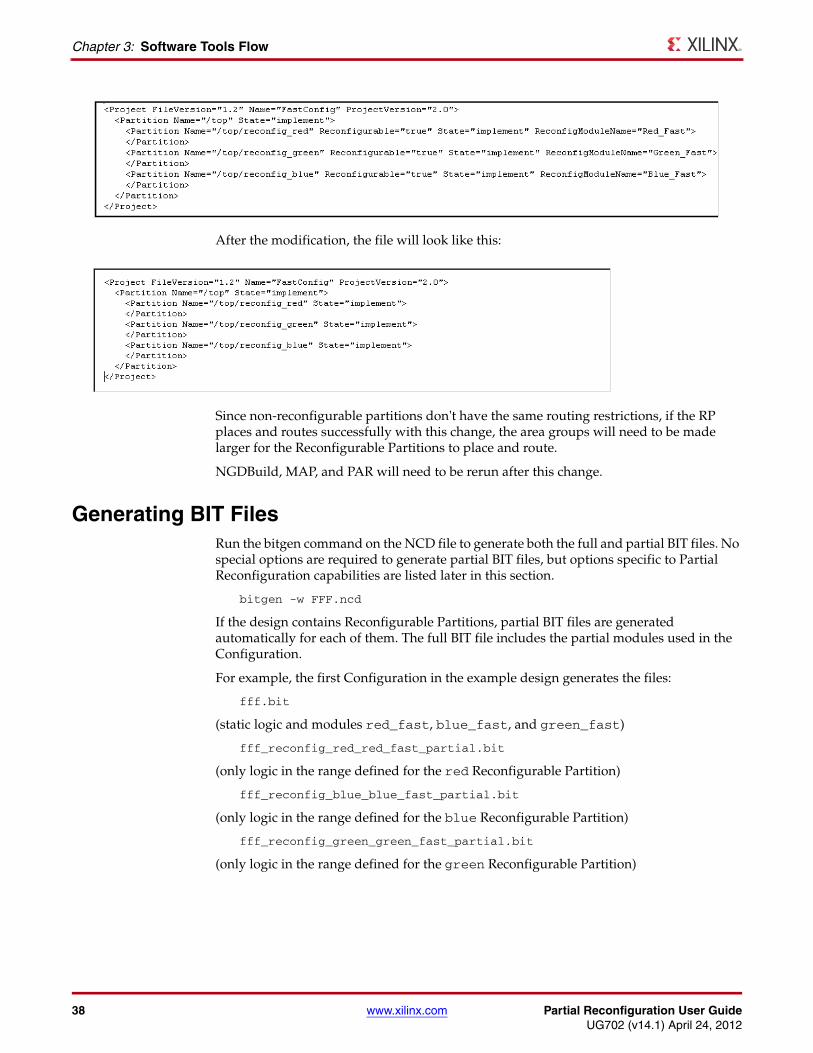
38 www.xilinx.com Partial Reconfiguration User GuideUG702 (v14.1) April 24, 2012
Chapter 3: Software Tools Flow
After the modification, the file will look like this:
Since non-reconfigurable partitions don't have the same routing restrictions, if the RP places and routes successfully with this change, the area groups will need to be made larger for the Reconfigurable Partitions to place and route.
NGDBuild, MAP, and PAR will need to be rerun after this change.
Generating BIT FilesRun the bitgen command on the NCD file to generate both the full and partial BIT files. No special options are required to generate partial BIT files, but options specific to Partial Reconfiguration capabilities are listed later in this section.
bitgen -w FFF.ncd
If the design contains Reconfigurable Partitions, partial BIT files are generated automatically for each of them. The full BIT file includes the partial modules used in the Configuration.
For example, the first Configuration in the example design generates the files:
fff.bit
(static logic and modules red_fast, blue_fast, and green_fast)
fff_reconfig_red_red_fast_partial.bit
(only logic in the range defined for the red Reconfigurable Partition)
fff_reconfig_blue_blue_fast_partial.bit
(only logic in the range defined for the blue Reconfigurable Partition)
fff_reconfig_green_green_fast_partial.bit
(only logic in the range defined for the green Reconfigurable Partition)
Partial Reconfiguration User Guide www.xilinx.com 39UG702 (v14.1) April 24, 2012
Report Files
The following BitGen options should be set for Partial Reconfiguration designs where applicable.
• –g ActiveReconfig:Yes
The ActiveReconfig option is typically used in PR to prevent shutting down the FPGA (prevents GHIGH and GSR assertion).
• -g Binary:Yes
This will generate a binary configuration with configuration data only (same as BIT file minus header information). Because the BIT file has header information of varying length (does not always fall on a Word boundary), a BIN file is often a preferred format to use for custom configuration interfaces.
• -g ConfigFallback:Disable
Use this option to prevent triggering a full device configuration after a configuration error (CRC error) on a partial bitstream. Use this option for Virtex-5 and newer architectures.
• –g CRC:enable
This is the default, and disabling the CRC is not recommended.
• -g Persist:Yes
Prohibits the use of the dual-purpose configuration pins as user I/O, which is required if Slave SelectMAP or Slave Serial modes are to be used for Partial Reconfiguration. This option should be used in conjunction with the CONFIG_MODE constraint to select the proper set of configuration pins to be reserved for post-configuration use. Consult the Constraints Guide (UG625) for the complete set of values for CONFIG_MODE (examples: S_SELECTMAP, S_SERIAL).
Do not use the BitGen -r option with the Partition-based Partial Reconfiguration flow. The -r switch supports the difference-based flow, where minor edits are made to a routed design and this option compares the changes in order to build a partial BIT file.
For more information on these and other BitGen Options, see the chapter titled “BitGen” in the Command Line Tools User Guide, (UG628).
Report FilesThe report files for NGDBuild, MAP, PAR, TRACE, and BitGen contain specific information for Reconfigurable Partitions. The report files are:
• NGDBuild Report
• MAP Report
• PAR Report
• TRACE Report
• Bitgen Report
The following sample reports are in a simplified format.
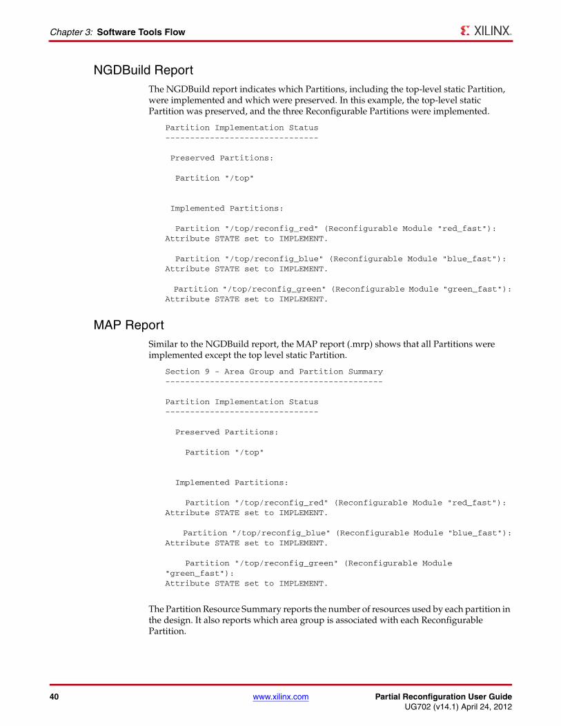
40 www.xilinx.com Partial Reconfiguration User GuideUG702 (v14.1) April 24, 2012
Chapter 3: Software Tools Flow
NGDBuild Report The NGDBuild report indicates which Partitions, including the top-level static Partition, were implemented and which were preserved. In this example, the top-level static Partition was preserved, and the three Reconfigurable Partitions were implemented.
Partition Implementation Status-------------------------------
Preserved Partitions:
Partition "/top"
Implemented Partitions:
Partition "/top/reconfig_red" (Reconfigurable Module "red_fast"):Attribute STATE set to IMPLEMENT.
Partition "/top/reconfig_blue" (Reconfigurable Module "blue_fast"):Attribute STATE set to IMPLEMENT.
Partition "/top/reconfig_green" (Reconfigurable Module "green_fast"):Attribute STATE set to IMPLEMENT.
MAP ReportSimilar to the NGDBuild report, the MAP report (.mrp) shows that all Partitions were implemented except the top level static Partition.
Section 9 - Area Group and Partition Summary--------------------------------------------
Partition Implementation Status-------------------------------
Preserved Partitions:
Partition "/top"
Implemented Partitions:
Partition "/top/reconfig_red" (Reconfigurable Module "red_fast"):Attribute STATE set to IMPLEMENT.
Partition "/top/reconfig_blue" (Reconfigurable Module "blue_fast"):Attribute STATE set to IMPLEMENT.
Partition "/top/reconfig_green" (Reconfigurable Module "green_fast"):Attribute STATE set to IMPLEMENT.
The Partition Resource Summary reports the number of resources used by each partition in the design. It also reports which area group is associated with each Reconfigurable Partition.
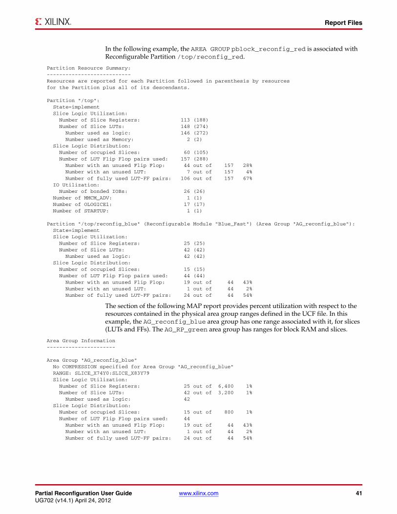
Partial Reconfiguration User Guide www.xilinx.com 41UG702 (v14.1) April 24, 2012
Report Files
In the following example, the AREA GROUP pblock_reconfig_red is associated with Reconfigurable Partition /top/reconfig_red.
Partition Resource Summary:---------------------------Resources are reported for each Partition followed in parenthesis by resourcesfor the Partition plus all of its descendants.
Partition "/top": State=implement Slice Logic Utilization: Number of Slice Registers: 113 (188) Number of Slice LUTs: 148 (274) Number used as logic: 146 (272) Number used as Memory: 2 (2) Slice Logic Distribution: Number of occupied Slices: 60 (105) Number of LUT Flip Flop pairs used: 157 (288) Number with an unused Flip Flop: 44 out of 157 28% Number with an unused LUT: 7 out of 157 4% Number of fully used LUT-FF pairs: 106 out of 157 67% IO Utilization: Number of bonded IOBs: 26 (26) Number of MMCM_ADV: 1 (1) Number of OLOGICE1: 17 (17) Number of STARTUP: 1 (1)
Partition "/top/reconfig_blue" (Reconfigurable Module "Blue_Fast") (Area Group "AG_reconfig_blue"): State=implement Slice Logic Utilization: Number of Slice Registers: 25 (25) Number of Slice LUTs: 42 (42) Number used as logic: 42 (42) Slice Logic Distribution: Number of occupied Slices: 15 (15) Number of LUT Flip Flop pairs used: 44 (44) Number with an unused Flip Flop: 19 out of 44 43% Number with an unused LUT: 1 out of 44 2% Number of fully used LUT-FF pairs: 24 out of 44 54%
The section of the following MAP report provides percent utilization with respect to the resources contained in the physical area group ranges defined in the UCF file. In this example, the AG_reconfig_blue area group has one range associated with it, for slices (LUTs and FFs). The AG_RP_green area group has ranges for block RAM and slices.
Area Group Information----------------------
Area Group "AG_reconfig_blue" No COMPRESSION specified for Area Group "AG_reconfig_blue" RANGE: SLICE_X74Y0:SLICE_X83Y79 Slice Logic Utilization: Number of Slice Registers: 25 out of 6,400 1% Number of Slice LUTs: 42 out of 3,200 1% Number used as logic: 42 Slice Logic Distribution: Number of occupied Slices: 15 out of 800 1% Number of LUT Flip Flop pairs used: 44 Number with an unused Flip Flop: 19 out of 44 43% Number with an unused LUT: 1 out of 44 2% Number of fully used LUT-FF pairs: 24 out of 44 54%
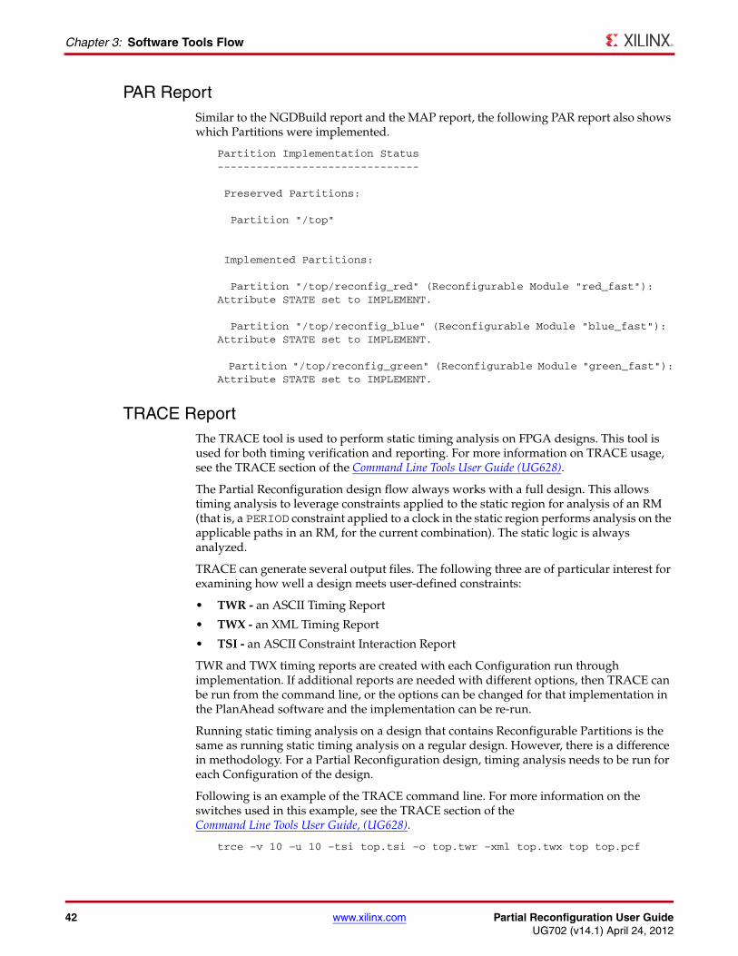
42 www.xilinx.com Partial Reconfiguration User GuideUG702 (v14.1) April 24, 2012
Chapter 3: Software Tools Flow
PAR ReportSimilar to the NGDBuild report and the MAP report, the following PAR report also shows which Partitions were implemented.
Partition Implementation Status-------------------------------
Preserved Partitions:
Partition "/top"
Implemented Partitions:
Partition "/top/reconfig_red" (Reconfigurable Module "red_fast"):Attribute STATE set to IMPLEMENT.
Partition "/top/reconfig_blue" (Reconfigurable Module "blue_fast"):Attribute STATE set to IMPLEMENT.
Partition "/top/reconfig_green" (Reconfigurable Module "green_fast"):Attribute STATE set to IMPLEMENT.
TRACE ReportThe TRACE tool is used to perform static timing analysis on FPGA designs. This tool is used for both timing verification and reporting. For more information on TRACE usage, see the TRACE section of the Command Line Tools User Guide (UG628).
The Partial Reconfiguration design flow always works with a full design. This allows timing analysis to leverage constraints applied to the static region for analysis of an RM (that is, a PERIOD constraint applied to a clock in the static region performs analysis on the applicable paths in an RM, for the current combination). The static logic is always analyzed.
TRACE can generate several output files. The following three are of particular interest for examining how well a design meets user-defined constraints:
• TWR - an ASCII Timing Report
• TWX - an XML Timing Report
• TSI - an ASCII Constraint Interaction Report
TWR and TWX timing reports are created with each Configuration run through implementation. If additional reports are needed with different options, then TRACE can be run from the command line, or the options can be changed for that implementation in the PlanAhead software and the implementation can be re-run.
Running static timing analysis on a design that contains Reconfigurable Partitions is the same as running static timing analysis on a regular design. However, there is a difference in methodology. For a Partial Reconfiguration design, timing analysis needs to be run for each Configuration of the design.
Following is an example of the TRACE command line. For more information on the switches used in this example, see the TRACE section of theCommand Line Tools User Guide, (UG628).
trce –v 10 –u 10 –tsi top.tsi –o top.twr –xml top.twx top top.pcf
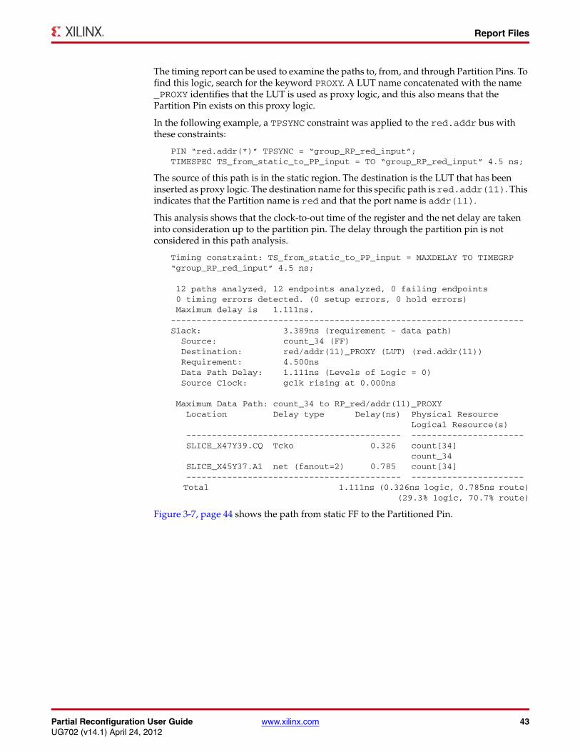
Partial Reconfiguration User Guide www.xilinx.com 43UG702 (v14.1) April 24, 2012
Report Files
The timing report can be used to examine the paths to, from, and through Partition Pins. To find this logic, search for the keyword PROXY. A LUT name concatenated with the name _PROXY identifies that the LUT is used as proxy logic, and this also means that the Partition Pin exists on this proxy logic.
In the following example, a TPSYNC constraint was applied to the red.addr bus with these constraints:
PIN “red.addr(*)” TPSYNC = “group_RP_red_input”;TIMESPEC TS_from_static_to_PP_input = TO “group_RP_red_input” 4.5 ns;
The source of this path is in the static region. The destination is the LUT that has been inserted as proxy logic. The destination name for this specific path is red.addr(11). This indicates that the Partition name is red and that the port name is addr(11).
This analysis shows that the clock-to-out time of the register and the net delay are taken into consideration up to the partition pin. The delay through the partition pin is not considered in this path analysis.
Timing constraint: TS_from_static_to_PP_input = MAXDELAY TO TIMEGRP “group_RP_red_input” 4.5 ns;
12 paths analyzed, 12 endpoints analyzed, 0 failing endpoints 0 timing errors detected. (0 setup errors, 0 hold errors) Maximum delay is 1.111ns.---------------------------------------------------------------------Slack: 3.389ns (requirement - data path) Source: count_34 (FF) Destination: red/addr(11)_PROXY (LUT) (red.addr(11)) Requirement: 4.500ns Data Path Delay: 1.111ns (Levels of Logic = 0) Source Clock: gclk rising at 0.000ns
Maximum Data Path: count_34 to RP_red/addr(11)_PROXY Location Delay type Delay(ns) Physical Resource Logical Resource(s) ------------------------------------------ ---------------------- SLICE_X47Y39.CQ Tcko 0.326 count[34] count_34 SLICE_X45Y37.A1 net (fanout=2) 0.785 count[34] ------------------------------------------ ---------------------- Total 1.111ns (0.326ns logic, 0.785ns route) (29.3% logic, 70.7% route)
Figure 3-7, page 44 shows the path from static FF to the Partitioned Pin.
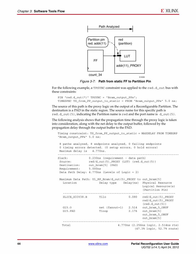
44 www.xilinx.com Partial Reconfiguration User GuideUG702 (v14.1) April 24, 2012
Chapter 3: Software Tools Flow
For the following example, a TPSYNC constraint was applied to the red.d_out bus with these constraints:
PIN "red.d_out(*)" TPSYNC = "Bram_output_PPs";TIMESPEC TS_from_PP_output_to_static = FROM "Bram_output_PPs" 5.0 ns;
The source of this path is the proxy logic on the output of a Reconfigurable Partition. The destination is a PAD in the static region. The source name for this specific path is red.d_out(5), indicating the Partition name is red and the port name is d_out(5).
The following analysis shows that the propagation time through the proxy logic is taken into consideration, along with the net delay to the output buffer, followed by the propagation delay through the output buffer to the PAD.
Timing constraint: TS_from_PP_output_to_static = MAXDELAY FROM TIMEGRP "Bram_output_PPs" 5.0 ns;
8 paths analyzed, 8 endpoints analyzed, 0 failing endpoints 0 timing errors detected. (0 setup errors, 0 hold errors) Maximum delay is 4.770ns.----------------------------------------------------------------------Slack: 0.230ns (requirement - data path) Source: red/d_out(5)_PROXY (LUT) (red.d_out(5)) Destination: out_bram[5] (PAD) Requirement: 5.000ns Data Path Delay: 4.770ns (Levels of Logic = 2)
Maximum Data Path: U1_RP_Bram/d_out(5)_PROXY to out_bram[5] Location Delay type Delay(ns) Physical Resource Logical Resource(s) (Partition Pin) -------------------------------------------- ------------------- SLICE_X33Y38.B Tilo 0.080 red/d_out(5)_PROXY red/d_out(5)_PROXY (red.d_out(5)) G15.O net (fanout=1) 2.514 out_bram_5_OBUF G15.PAD Tioop 2.176 out_bram[5] out_bram_5_OBUF out_bram[5] -------------------------------------------- --------------------- Total 4.770ns (2.256ns logic, 2.514ns rte) (47.3% logic, 52.7% route)
X-Ref Target - Figure 3-7
Figure 3-7: Path from static FF to Partition PinX12028
Path Analyzed
count_34
Partition pinred. addr(11)
red(partition)
LUTFF
addr(11)_PROXY
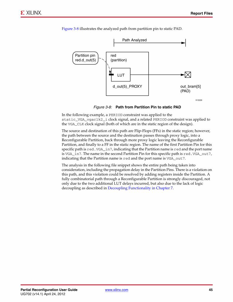
Partial Reconfiguration User Guide www.xilinx.com 45UG702 (v14.1) April 24, 2012
Report Files
Figure 3-8 illustrates the analyzed path from partition pin to static PAD.
In the following example, a PERIOD constraint was applied to the static_VGA_vgaclk2_i clock signal, and a related PERIOD constraint was applied to the VGA_CLK clock signal (both of which are in the static region of the design).
The source and destination of this path are Flip-Flops (FFs) in the static region; however, the path between the source and the destination passes through proxy logic, into a Reconfigurable Partition, back through more proxy logic leaving the Reconfigurable Partition, and finally to a FF in the static region. The name of the first Partition Pin for this specific path is red.VGA_in7, indicating that the Partition name is red and the port name is VGA_in7. The name in the second Partition Pin for this specific path is red.VGA_out7, indicating that the Partition name is red and the port name is VGA_out7.
The analysis in the following file snippet shows the entire path being taken into consideration, including the propagation delay in the Partition Pins. There is a violation on this path, and this violation could be resolved by adding registers inside the Partition. A fully combinatorial path through a Reconfigurable Partition is strongly discouraged, not only due to the two additional LUT delays incurred, but also due to the lack of logic decoupling as described in Decoupling Functionality in Chapter 7.
X-Ref Target - Figure 3-8
Figure 3-8: Path from Partition Pin to static PAD
X12029
Path Analyzed
Partition pinred.d_out(5)
red(partition)
LUT
d_out(5)_PROXY out_bram[5](PAD)
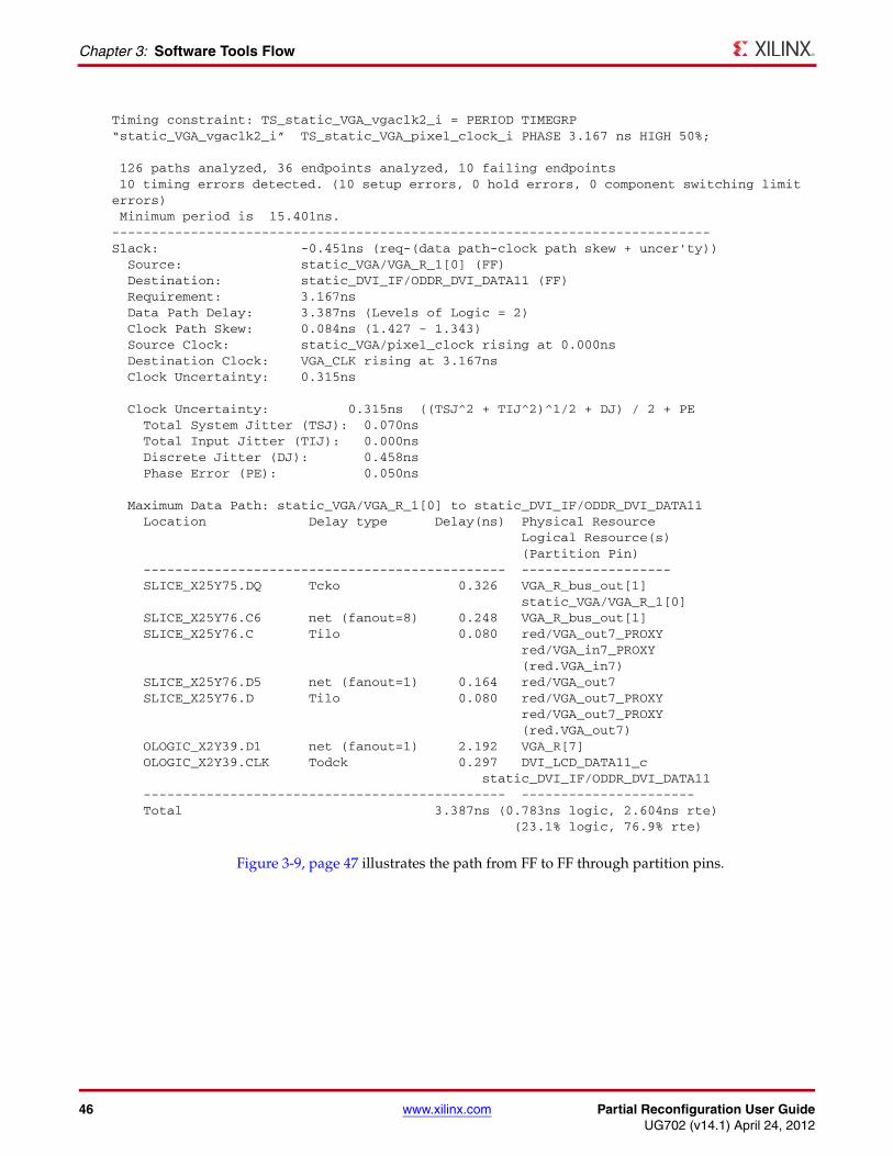
46 www.xilinx.com Partial Reconfiguration User GuideUG702 (v14.1) April 24, 2012
Chapter 3: Software Tools Flow
Figure 3-9, page 47 illustrates the path from FF to FF through partition pins.
Timing constraint: TS_static_VGA_vgaclk2_i = PERIOD TIMEGRP “static_VGA_vgaclk2_i” TS_static_VGA_pixel_clock_i PHASE 3.167 ns HIGH 50%;
126 paths analyzed, 36 endpoints analyzed, 10 failing endpoints 10 timing errors detected. (10 setup errors, 0 hold errors, 0 component switching limit errors) Minimum period is 15.401ns.----------------------------------------------------------------------------Slack: -0.451ns (req-(data path-clock path skew + uncer'ty)) Source: static_VGA/VGA_R_1[0] (FF) Destination: static_DVI_IF/ODDR_DVI_DATA11 (FF) Requirement: 3.167ns Data Path Delay: 3.387ns (Levels of Logic = 2) Clock Path Skew: 0.084ns (1.427 - 1.343) Source Clock: static_VGA/pixel_clock rising at 0.000ns Destination Clock: VGA_CLK rising at 3.167ns Clock Uncertainty: 0.315ns
Clock Uncertainty: 0.315ns ((TSJ^2 + TIJ^2)^1/2 + DJ) / 2 + PE Total System Jitter (TSJ): 0.070ns Total Input Jitter (TIJ): 0.000ns Discrete Jitter (DJ): 0.458ns Phase Error (PE): 0.050ns
Maximum Data Path: static_VGA/VGA_R_1[0] to static_DVI_IF/ODDR_DVI_DATA11 Location Delay type Delay(ns) Physical Resource Logical Resource(s) (Partition Pin) ---------------------------------------------- ------------------- SLICE_X25Y75.DQ Tcko 0.326 VGA_R_bus_out[1] static_VGA/VGA_R_1[0] SLICE_X25Y76.C6 net (fanout=8) 0.248 VGA_R_bus_out[1] SLICE_X25Y76.C Tilo 0.080 red/VGA_out7_PROXY red/VGA_in7_PROXY (red.VGA_in7) SLICE_X25Y76.D5 net (fanout=1) 0.164 red/VGA_out7 SLICE_X25Y76.D Tilo 0.080 red/VGA_out7_PROXY red/VGA_out7_PROXY (red.VGA_out7) OLOGIC_X2Y39.D1 net (fanout=1) 2.192 VGA_R[7] OLOGIC_X2Y39.CLK Todck 0.297 DVI_LCD_DATA11_c static_DVI_IF/ODDR_DVI_DATA11 ---------------------------------------------- ---------------------- Total 3.387ns (0.783ns logic, 2.604ns rte) (23.1% logic, 76.9% rte)
Partial Reconfiguration User Guide www.xilinx.com 47UG702 (v14.1) April 24, 2012
Report Files
Bitgen ReportThe Bitgen executable creates a report file for the full BIT file in addition to each partial BIT file. The full BIT file report lists all of the Reconfigurable Modules included in the full BIT file and indicates that it is not a partial BIT file with the ActiveReconfig = No setting.
...Partition “/top/reconfig_red” (Reconfigurable Module “red_fast”)Partition “/top/reconfig_blue” (Reconfigurable Module “blue_fast”)Partition “/top/reconfig_green” (Reconfigurable Module “green_fast”)...Summary of Bitgen Options:+----------------------+----------------------+| ActiveReconfig | No* |+----------------------+----------------------+| Partial | (Not Specified)* |+----------------------+----------------------+...* Default setting.
The report for the partial BIT file indicates that it is a partial BIT file and which Partition and Reconfigurable Module to which it is associated.
...Summary of Bitgen Options:+----------------------+----------------------+| ActiveReconfig | Yes |+----------------------+----------------------+| Partial | reconfig_red |+----------------------+----------------------+...Creating bit stream for Partition “/top/reconfig_red” (Reconfigurable Module “red_fast”)Creating bit map...Saving bit stream in “fff_reconfig_red_red_fast_partial.bit”.
X-Ref Target - Figure 3-9
Figure 3-9: Path from FF to FF through Partition Pins
X12030
Path Analyzed
static_VGA/VGA_R_1[0]
static_DVI_IF/ODDR_DVI_DATA11
Partition pinred. VGA_out7
Partition pinred. VGA_in7
red(partition)
LUT
FF FF
LUT
VGA_in7_PROXY VGA_out7_PROXY
48 www.xilinx.com Partial Reconfiguration User GuideUG702 (v14.1) April 24, 2012
Chapter 3: Software Tools Flow
pr_verifyFor Partial Reconfigurable designs to work in hardware, static logic's placement and routing must be consistent between all configurations. In addition, proxy logic must be placed in the same locations and clock spine routing must match. The pr_verify utility is used to compare routed NCD files from two or more configurations created for a Partial Reconfiguration design to validate that all imported resources match. These resources include:
• Global Clock Spines – Each global clock must have clock spines routed within the same clock regions in all configurations.
• Regional Clock Spines – For architectures except for Virtex-5, each regional clock must have clock spines routed within the same clock regions in all configurations.
• Proxy logic – Proxy logic, although logically part of the static design, must be placed at the same locations within the Area Groups allocated for the Reconfigurable Partitions.
• Partition Interfaces – Each RP must have the same ports in and out of the RM in each configuration.
pr_verify Usage pr_verify can be run either in PlanAhead or on the command line. For information on running it within PlanAhead, see Verifying Configurations in Chapter 4.
Command Line Syntax
pr_verify [-verbose] <design1[.ncd]> <design2[.ncd]> [<design[.ncd]>][-o <outfile>]
-verbose – Report all messages
-o <outfile> – Specify the output file name, including extension. If this option is not used, the default file pr_verify.log is created.
<design*[.ncd]> – Enter a list of at least two NCD files to be compared.
For the example design appearing in this user guide, the pr_verify command line would be as follows.
pr_verify -verbose ./FastConfig/FastConfig.ncd ./SlowConfig/SlowConfig.ncd ./FSFConfig/FSFConfig.ncd ./BlankConfig/BlankConfig.ncd
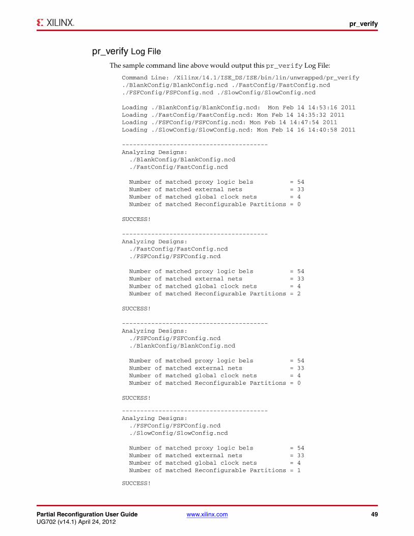
Partial Reconfiguration User Guide www.xilinx.com 49UG702 (v14.1) April 24, 2012
pr_verify
pr_verify Log File
The sample command line above would output this pr_verify Log File:
Command Line: /Xilinx/14.1/ISE_DS/ISE/bin/lin/unwrapped/pr_verify./BlankConfig/BlankConfig.ncd ./FastConfig/FastConfig.ncd./FSFConfig/FSFConfig.ncd ./SlowConfig/SlowConfig.ncd
Loading ./BlankConfig/BlankConfig.ncd: Mon Feb 14 14:53:16 2011Loading ./FastConfig/FastConfig.ncd: Mon Feb 14 14:35:32 2011Loading ./FSFConfig/FSFConfig.ncd: Mon Feb 14 14:47:54 2011Loading ./SlowConfig/SlowConfig.ncd: Mon Feb 14 16 14:40:58 2011
----------------------------------------Analyzing Designs: ./BlankConfig/BlankConfig.ncd ./FastConfig/FastConfig.ncd
Number of matched proxy logic bels = 54 Number of matched external nets = 33 Number of matched global clock nets = 4 Number of matched Reconfigurable Partitions = 0
SUCCESS!
----------------------------------------Analyzing Designs: ./FastConfig/FastConfig.ncd ./FSFConfig/FSFConfig.ncd
Number of matched proxy logic bels = 54 Number of matched external nets = 33 Number of matched global clock nets = 4 Number of matched Reconfigurable Partitions = 2
SUCCESS!
----------------------------------------Analyzing Designs: ./FSFConfig/FSFConfig.ncd ./BlankConfig/BlankConfig.ncd
Number of matched proxy logic bels = 54 Number of matched external nets = 33 Number of matched global clock nets = 4 Number of matched Reconfigurable Partitions = 0
SUCCESS!
----------------------------------------Analyzing Designs: ./FSFConfig/FSFConfig.ncd ./SlowConfig/SlowConfig.ncd
Number of matched proxy logic bels = 54 Number of matched external nets = 33 Number of matched global clock nets = 4 Number of matched Reconfigurable Partitions = 1
SUCCESS!
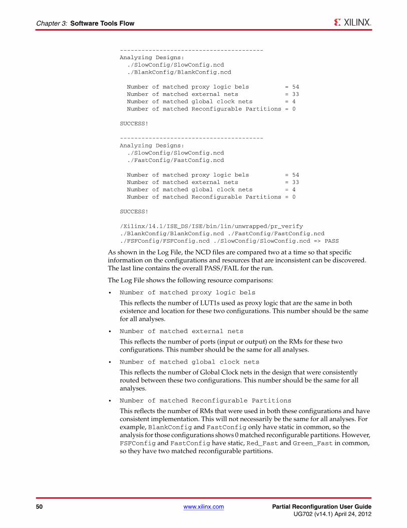
50 www.xilinx.com Partial Reconfiguration User GuideUG702 (v14.1) April 24, 2012
Chapter 3: Software Tools Flow
----------------------------------------Analyzing Designs: ./SlowConfig/SlowConfig.ncd ./BlankConfig/BlankConfig.ncd
Number of matched proxy logic bels = 54 Number of matched external nets = 33 Number of matched global clock nets = 4 Number of matched Reconfigurable Partitions = 0
SUCCESS!
----------------------------------------Analyzing Designs: ./SlowConfig/SlowConfig.ncd ./FastConfig/FastConfig.ncd
Number of matched proxy logic bels = 54 Number of matched external nets = 33 Number of matched global clock nets = 4 Number of matched Reconfigurable Partitions = 0
SUCCESS!
/Xilinx/14.1/ISE_DS/ISE/bin/lin/unwrapped/pr_verify./BlankConfig/BlankConfig.ncd ./FastConfig/FastConfig.ncd./FSFConfig/FSFConfig.ncd ./SlowConfig/SlowConfig.ncd => PASS
As shown in the Log File, the NCD files are compared two at a time so that specific information on the configurations and resources that are inconsistent can be discovered. The last line contains the overall PASS/FAIL for the run.
The Log File shows the following resource comparisons:
• Number of matched proxy logic bels
This reflects the number of LUT1s used as proxy logic that are the same in both existence and location for these two configurations. This number should be the same for all analyses.
• Number of matched external nets
This reflects the number of ports (input or output) on the RMs for these two configurations. This number should be the same for all analyses.
• Number of matched global clock nets
This reflects the number of Global Clock nets in the design that were consistently routed between these two configurations. This number should be the same for all analyses.
• Number of matched Reconfigurable Partitions
This reflects the number of RMs that were used in both these configurations and have consistent implementation. This will not necessarily be the same for all analyses. For example, BlankConfig and FastConfig only have static in common, so the analysis for those configurations shows 0 matched reconfigurable partitions. However, FSFConfig and FastConfig have static, Red_Fast and Green_Fast in common, so they have two matched reconfigurable partitions.
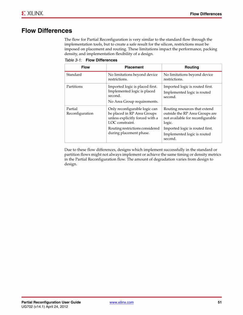
Partial Reconfiguration User Guide www.xilinx.com 51UG702 (v14.1) April 24, 2012
Flow Differences
Flow DifferencesThe flow for Partial Reconfiguration is very similar to the standard flow through the implementation tools, but to create a safe result for the silicon, restrictions must be imposed on placement and routing. These limitations impact the performance, packing density, and implementation flexibility of a design.
Due to these flow differences, designs which implement successfully in the standard or partition flows might not always implement or achieve the same timing or density metrics in the Partial Reconfiguration flow. The amount of degradation varies from design to design.
Table 3-1: Flow Differences
Flow Placement Routing
Standard No limitations beyond device restrictions.
No limitations beyond device restrictions.
Partitions Imported logic is placed first. Implemented logic is placed second.
No Area Group requirements.
Imported logic is routed first.
Implemented logic is routed second.
Partial Reconfiguration
Only reconfigurable logic can be placed in RP Area Groups unless explicitly forced with a LOC constraint.
Routing restrictions considered during placement phase.
Routing resources that extend outside the RP Area Groups are not available for reconfigurable logic.
Imported logic is routed first.
Implemented logic is routed second.

52 www.xilinx.com Partial Reconfiguration User GuideUG702 (v14.1) April 24, 2012
Chapter 3: Software Tools Flow
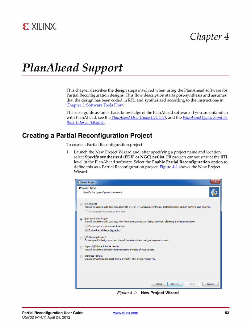
Partial Reconfiguration User Guide www.xilinx.com 53UG702 (v14.1) April 24, 2012
Chapter 4
PlanAhead Support
This chapter describes the design steps involved when using the PlanAhead software for Partial Reconfiguration designs. This flow description starts post-synthesis and assumes that the design has been coded in RTL and synthesized according to the instructions in Chapter 3, Software Tools Flow.
This user guide assumes basic knowledge of the PlanAhead software. If you are unfamiliar with PlanAhead, see the PlanAhead User Guide (UG632), and the PlanAhead Quick Front to Back Tutorial (UG673).
Creating a Partial Reconfiguration ProjectTo create a Partial Reconfiguration project:
1. Launch the New Project Wizard and, after specifying a project name and location, select Specify synthesized (EDIF or NGC) netlist. PR projects cannot start at the RTL level in the PlanAhead software. Select the Enable Partial Reconfiguration option to define this as a Partial Reconfiguration project. Figure 4-1 shows the New Project Wizard.
X-Ref Target - Figure 4-1
Figure 4-1: New Project Wizard
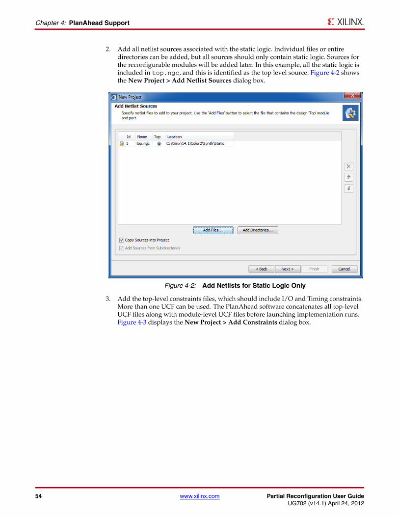
54 www.xilinx.com Partial Reconfiguration User GuideUG702 (v14.1) April 24, 2012
Chapter 4: PlanAhead Support
2. Add all netlist sources associated with the static logic. Individual files or entire directories can be added, but all sources should only contain static logic. Sources for the reconfigurable modules will be added later. In this example, all the static logic is included in top.ngc, and this is identified as the top level source. Figure 4-2 shows the New Project > Add Netlist Sources dialog box.
3. Add the top-level constraints files, which should include I/O and Timing constraints. More than one UCF can be used. The PlanAhead software concatenates all top-level UCF files along with module-level UCF files before launching implementation runs. Figure 4-3 displays the New Project > Add Constraints dialog box.
X-Ref Target - Figure 4-2
Figure 4-2: Add Netlists for Static Logic Only
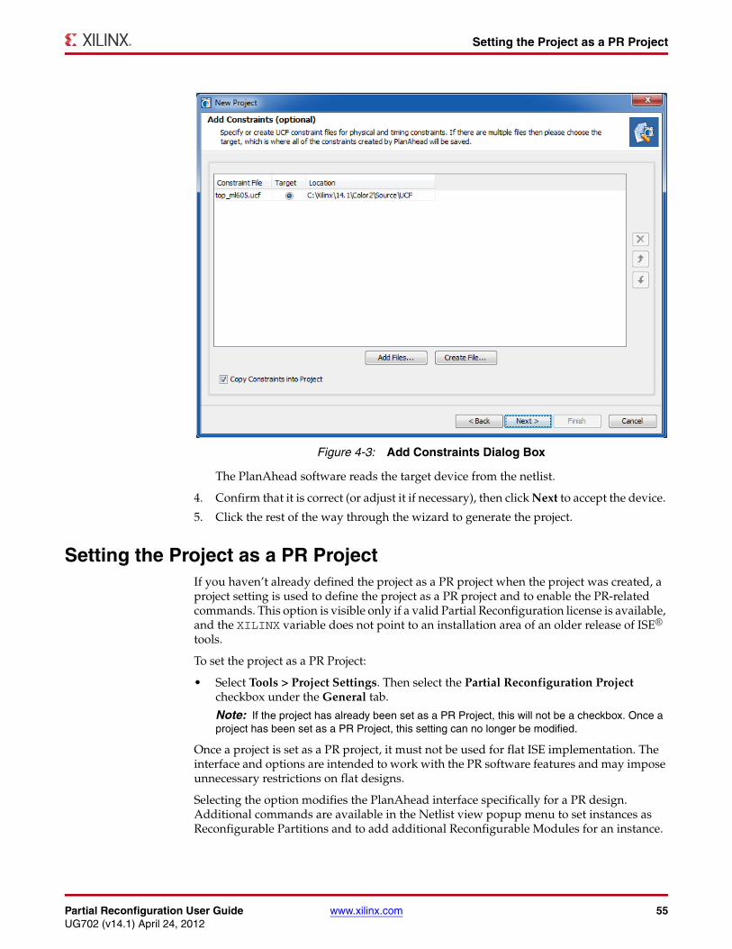
Partial Reconfiguration User Guide www.xilinx.com 55UG702 (v14.1) April 24, 2012
Setting the Project as a PR Project
The PlanAhead software reads the target device from the netlist.
4. Confirm that it is correct (or adjust it if necessary), then click Next to accept the device.
5. Click the rest of the way through the wizard to generate the project.
Setting the Project as a PR ProjectIf you haven’t already defined the project as a PR project when the project was created, a project setting is used to define the project as a PR project and to enable the PR-related commands. This option is visible only if a valid Partial Reconfiguration license is available, and the XILINX variable does not point to an installation area of an older release of ISE® tools.
To set the project as a PR Project:
• Select Tools > Project Settings. Then select the Partial Reconfiguration Project checkbox under the General tab.
Note: If the project has already been set as a PR Project, this will not be a checkbox. Once a project has been set as a PR Project, this setting can no longer be modified.
Once a project is set as a PR project, it must not be used for flat ISE implementation. The interface and options are intended to work with the PR software features and may impose unnecessary restrictions on flat designs.
Selecting the option modifies the PlanAhead interface specifically for a PR design. Additional commands are available in the Netlist view popup menu to set instances as Reconfigurable Partitions and to add additional Reconfigurable Modules for an instance.
X-Ref Target - Figure 4-3
Figure 4-3: Add Constraints Dialog Box
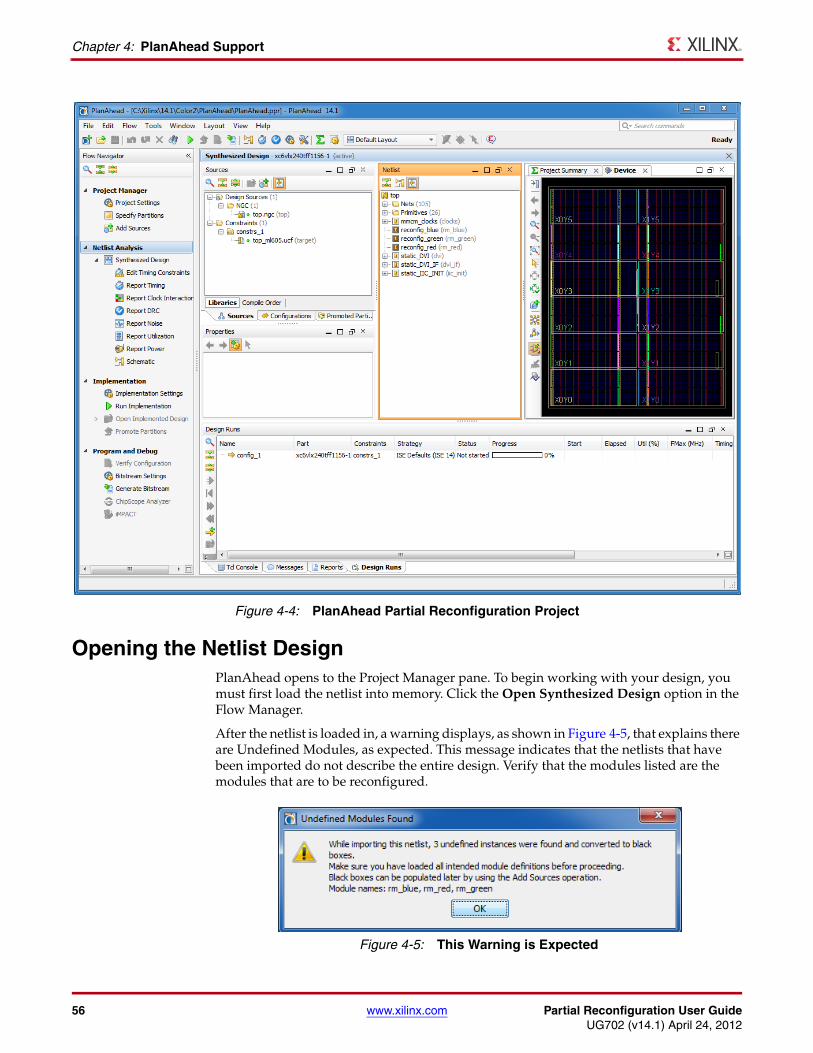
56 www.xilinx.com Partial Reconfiguration User GuideUG702 (v14.1) April 24, 2012
Chapter 4: PlanAhead Support
Opening the Netlist DesignPlanAhead opens to the Project Manager pane. To begin working with your design, you must first load the netlist into memory. Click the Open Synthesized Design option in the Flow Manager.
After the netlist is loaded in, a warning displays, as shown in Figure 4-5, that explains there are Undefined Modules, as expected. This message indicates that the netlists that have been imported do not describe the entire design. Verify that the modules listed are the modules that are to be reconfigured.
X-Ref Target - Figure 4-4
Figure 4-4: PlanAhead Partial Reconfiguration Project
X-Ref Target - Figure 4-5
Figure 4-5: This Warning is Expected
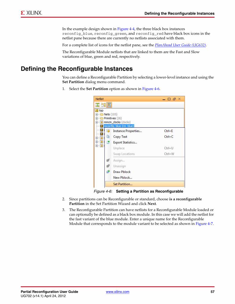
Partial Reconfiguration User Guide www.xilinx.com 57UG702 (v14.1) April 24, 2012
Defining the Reconfigurable Instances
In the example design shown in Figure 4-4, the three black box instances reconfig_blue, reconfig_green, and reconfig_red have black box icons in the netlist pane because there are currently no netlists associated with them.
For a complete list of icons for the netlist pane, see the PlanAhead User Guide (UG632).
The Reconfigurable Module netlists that are linked to them are the Fast and Slow variations of blue, green and red, respectively.
Defining the Reconfigurable InstancesYou can define a Reconfigurable Partition by selecting a lower-level instance and using the Set Partition dialog menu command.
1. Select the Set Partition option as shown in Figure 4-6.
2. Since partitions can be Reconfigurable or standard, choose is a reconfigurable Partition in the Set Partition Wizard and click Next.
3. The Reconfigurable Partition can have netlists for a Reconfigurable Module loaded or can optionally be defined as a black box module. In this case we will add the netlist for the fast variant of the blue module. Enter a unique name for the Reconfigurable Module that corresponds to the module variant to be selected as shown in Figure 4-7.
X-Ref Target - Figure 4-6
Figure 4-6: Setting a Partition as Reconfigurable
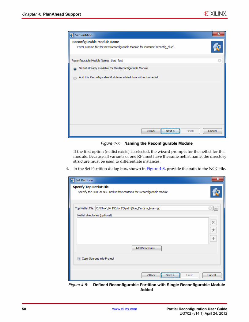
58 www.xilinx.com Partial Reconfiguration User GuideUG702 (v14.1) April 24, 2012
Chapter 4: PlanAhead Support
If the first option (netlist exists) is selected, the wizard prompts for the netlist for this module. Because all variants of one RP must have the same netlist name, the directory structure must be used to differentiate instances.
4. In the Set Partition dialog box, shown in Figure 4-8, provide the path to the NGC file.
X-Ref Target - Figure 4-7
Figure 4-7: Naming the Reconfigurable Module
X-Ref Target - Figure 4-8
Figure 4-8: Defined Reconfigurable Partition with Single Reconfigurable Module Added
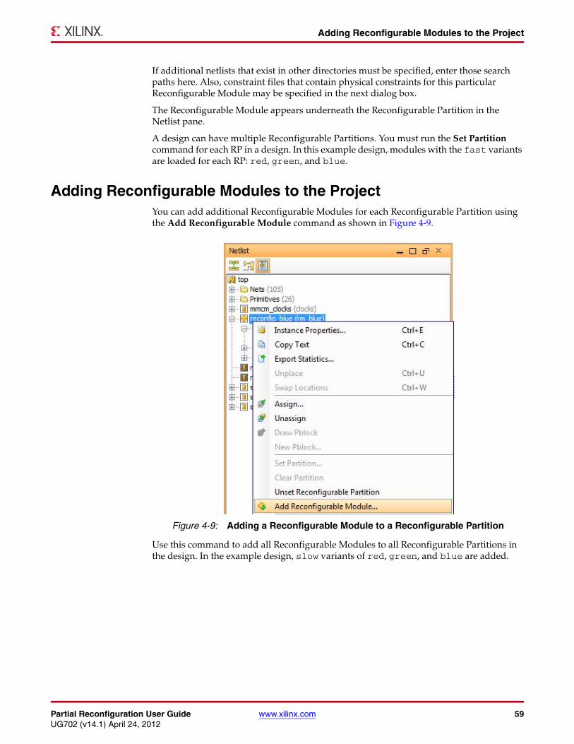
Partial Reconfiguration User Guide www.xilinx.com 59UG702 (v14.1) April 24, 2012
Adding Reconfigurable Modules to the Project
If additional netlists that exist in other directories must be specified, enter those search paths here. Also, constraint files that contain physical constraints for this particular Reconfigurable Module may be specified in the next dialog box.
The Reconfigurable Module appears underneath the Reconfigurable Partition in the Netlist pane.
A design can have multiple Reconfigurable Partitions. You must run the Set Partition command for each RP in a design. In this example design, modules with the fast variants are loaded for each RP: red, green, and blue.
Adding Reconfigurable Modules to the ProjectYou can add additional Reconfigurable Modules for each Reconfigurable Partition using the Add Reconfigurable Module command as shown in Figure 4-9.
Use this command to add all Reconfigurable Modules to all Reconfigurable Partitions in the design. In the example design, slow variants of red, green, and blue are added.
X-Ref Target - Figure 4-9
Figure 4-9: Adding a Reconfigurable Module to a Reconfigurable Partition
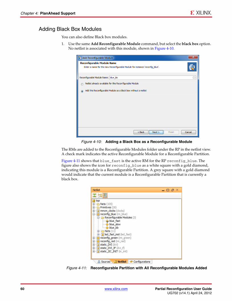
60 www.xilinx.com Partial Reconfiguration User GuideUG702 (v14.1) April 24, 2012
Chapter 4: PlanAhead Support
Adding Black Box ModulesYou can also define Black box modules.
1. Use the same Add Reconfigurable Module command, but select the black box option. No netlist is associated with this module, shown in Figure 4-10.
The RMs are added to the Reconfigurable Modules folder under the RP in the netlist view. A check mark indicates the active Reconfigurable Module for a Reconfigurable Partition.
Figure 4-11 shows that blue_fast is the active RM for the RP reconfig_blue. The figure also shows the icon for reconfig_blue as a white square with a gold diamond, indicating this module is a Reconfigurable Partition. A grey square with a gold diamond would indicate that the current module is a Reconfigurable Partition that is currently a black box.
X-Ref Target - Figure 4-10
Figure 4-10: Adding a Black Box as a Reconfigurable Module
X-Ref Target - Figure 4-11
Figure 4-11: Reconfigurable Partition with All Reconfigurable Modules Added
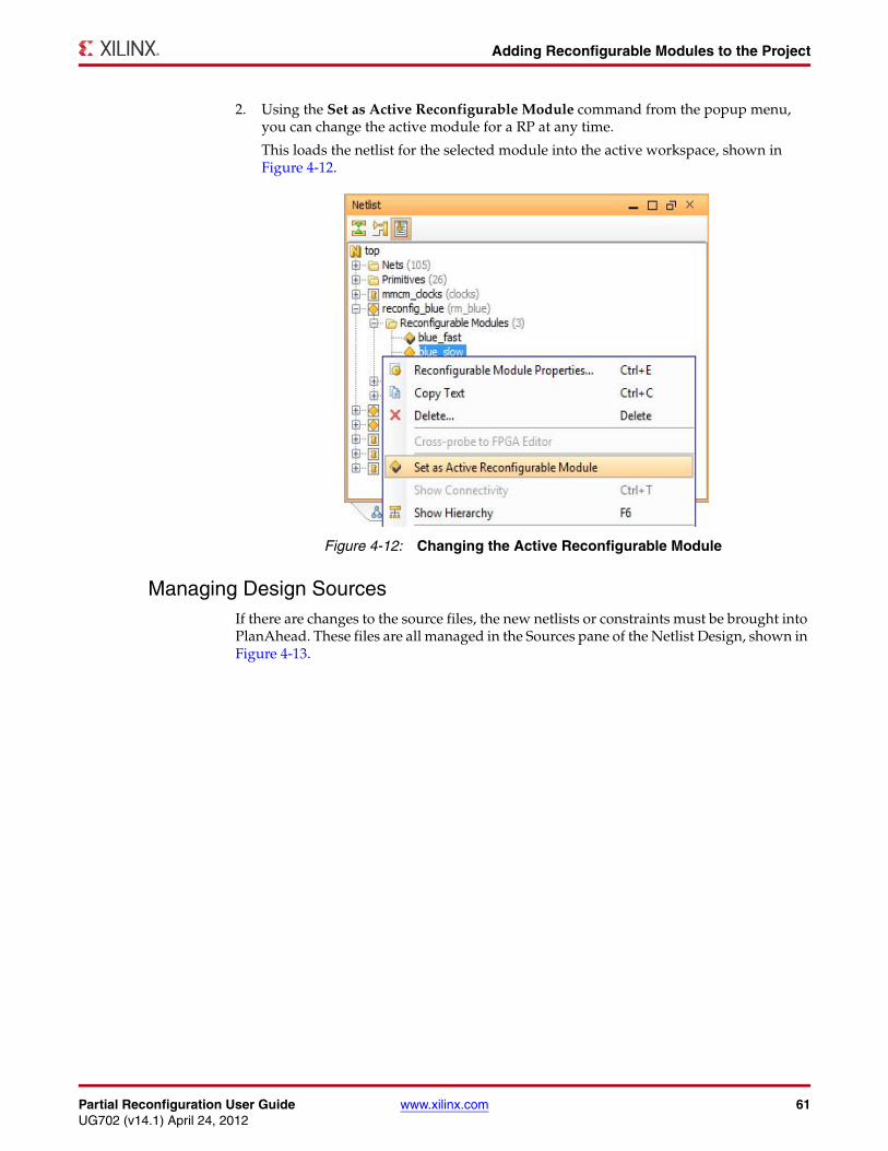
Partial Reconfiguration User Guide www.xilinx.com 61UG702 (v14.1) April 24, 2012
Adding Reconfigurable Modules to the Project
2. Using the Set as Active Reconfigurable Module command from the popup menu, you can change the active module for a RP at any time.
This loads the netlist for the selected module into the active workspace, shown in Figure 4-12.
Managing Design SourcesIf there are changes to the source files, the new netlists or constraints must be brought into PlanAhead. These files are all managed in the Sources pane of the Netlist Design, shown in Figure 4-13.
X-Ref Target - Figure 4-12
Figure 4-12: Changing the Active Reconfigurable Module
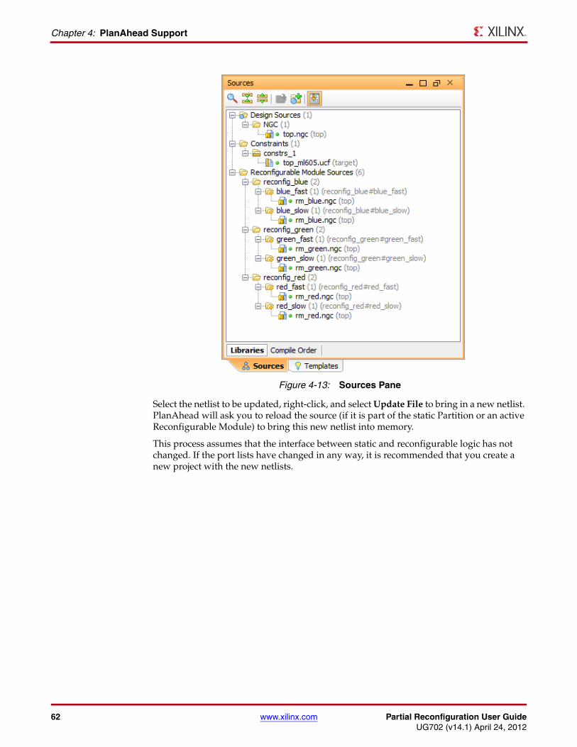
62 www.xilinx.com Partial Reconfiguration User GuideUG702 (v14.1) April 24, 2012
Chapter 4: PlanAhead Support
Select the netlist to be updated, right-click, and select Update File to bring in a new netlist. PlanAhead will ask you to reload the source (if it is part of the static Partition or an active Reconfigurable Module) to bring this new netlist into memory.
This process assumes that the interface between static and reconfigurable logic has not changed. If the port lists have changed in any way, it is recommended that you create a new project with the new netlists.
X-Ref Target - Figure 4-13
Figure 4-13: Sources Pane
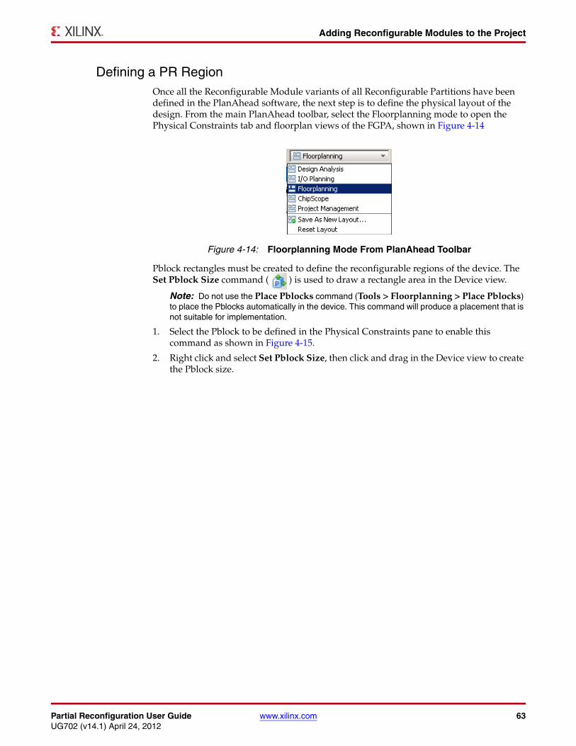
Partial Reconfiguration User Guide www.xilinx.com 63UG702 (v14.1) April 24, 2012
Adding Reconfigurable Modules to the Project
Defining a PR RegionOnce all the Reconfigurable Module variants of all Reconfigurable Partitions have been defined in the PlanAhead software, the next step is to define the physical layout of the design. From the main PlanAhead toolbar, select the Floorplanning mode to open the Physical Constraints tab and floorplan views of the FGPA, shown in Figure 4-14
Pblock rectangles must be created to define the reconfigurable regions of the device. The Set Pblock Size command ( ) is used to draw a rectangle area in the Device view.
Note: Do not use the Place Pblocks command (Tools > Floorplanning > Place Pblocks) to place the Pblocks automatically in the device. This command will produce a placement that is not suitable for implementation.
1. Select the Pblock to be defined in the Physical Constraints pane to enable this command as shown in Figure 4-15.
2. Right click and select Set Pblock Size, then click and drag in the Device view to create the Pblock size.
X-Ref Target - Figure 4-14
Figure 4-14: Floorplanning Mode From PlanAhead Toolbar
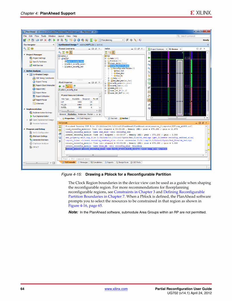
64 www.xilinx.com Partial Reconfiguration User GuideUG702 (v14.1) April 24, 2012
Chapter 4: PlanAhead Support
The Clock Region boundaries in the device view can be used as a guide when shaping the reconfigurable region. For more recommendations for floorplanning reconfigurable regions, see Constraints in Chapter 3 and Defining Reconfigurable Partition Boundaries in Chapter 7. When a Pblock is defined, the PlanAhead software prompts you to select the resources to be constrained in that region as shown in Figure 4-16, page 65.
Note: In the PlanAhead software, submodule Area Groups within an RP are not permitted.
X-Ref Target - Figure 4-15
Figure 4-15: Drawing a Pblock for a Reconfigurable Partition
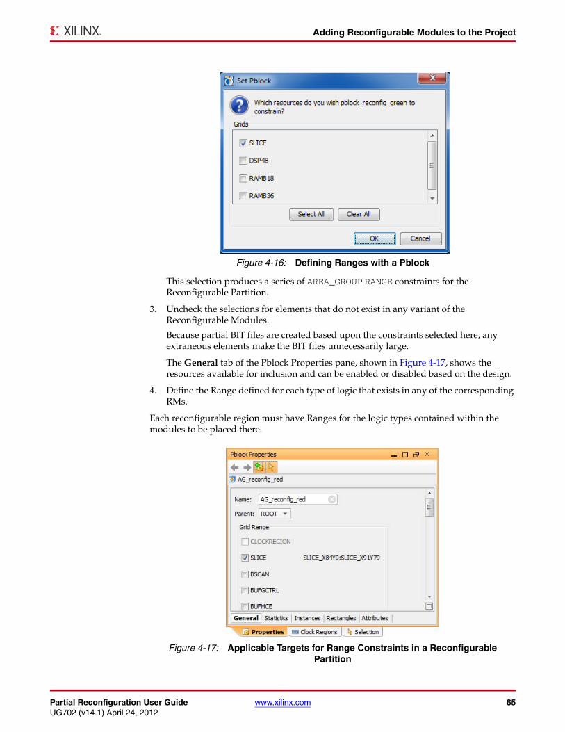
Partial Reconfiguration User Guide www.xilinx.com 65UG702 (v14.1) April 24, 2012
Adding Reconfigurable Modules to the Project
This selection produces a series of AREA_GROUP RANGE constraints for the Reconfigurable Partition.
3. Uncheck the selections for elements that do not exist in any variant of the Reconfigurable Modules.
Because partial BIT files are created based upon the constraints selected here, any extraneous elements make the BIT files unnecessarily large.
The General tab of the Pblock Properties pane, shown in Figure 4-17, shows the resources available for inclusion and can be enabled or disabled based on the design.
4. Define the Range defined for each type of logic that exists in any of the corresponding RMs.
Each reconfigurable region must have Ranges for the logic types contained within the modules to be placed there.
X-Ref Target - Figure 4-16
Figure 4-16: Defining Ranges with a Pblock
X-Ref Target - Figure 4-17
Figure 4-17: Applicable Targets for Range Constraints in a Reconfigurable Partition
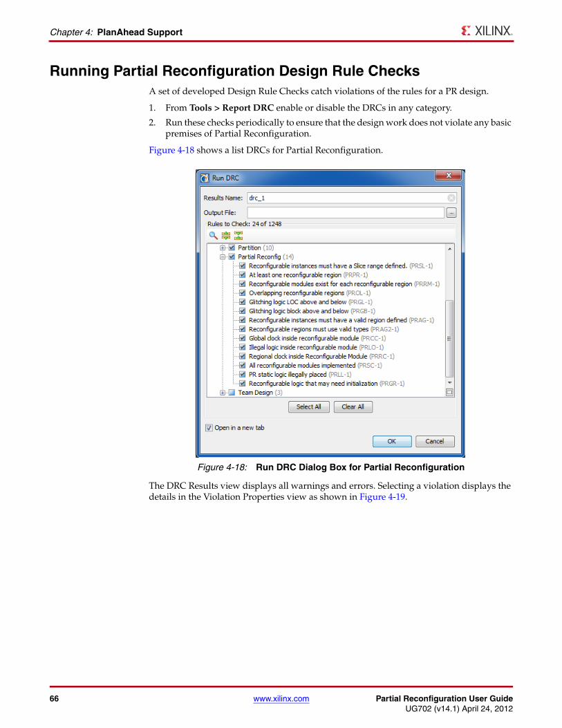
66 www.xilinx.com Partial Reconfiguration User GuideUG702 (v14.1) April 24, 2012
Chapter 4: PlanAhead Support
Running Partial Reconfiguration Design Rule ChecksA set of developed Design Rule Checks catch violations of the rules for a PR design.
1. From Tools > Report DRC enable or disable the DRCs in any category.
2. Run these checks periodically to ensure that the design work does not violate any basic premises of Partial Reconfiguration.
Figure 4-18 shows a list DRCs for Partial Reconfiguration.
The DRC Results view displays all warnings and errors. Selecting a violation displays the details in the Violation Properties view as shown in Figure 4-19.
X-Ref Target - Figure 4-18
Figure 4-18: Run DRC Dialog Box for Partial Reconfiguration
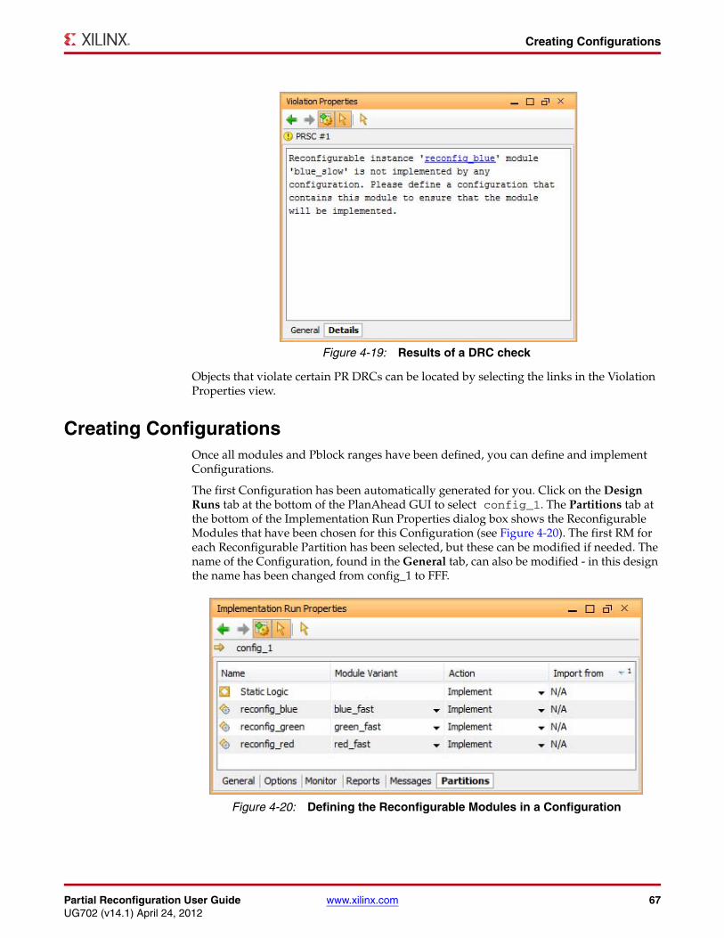
Partial Reconfiguration User Guide www.xilinx.com 67UG702 (v14.1) April 24, 2012
Creating Configurations
Objects that violate certain PR DRCs can be located by selecting the links in the Violation Properties view.
Creating ConfigurationsOnce all modules and Pblock ranges have been defined, you can define and implement Configurations.
The first Configuration has been automatically generated for you. Click on the Design Runs tab at the bottom of the PlanAhead GUI to select config_1. The Partitions tab at the bottom of the Implementation Run Properties dialog box shows the Reconfigurable Modules that have been chosen for this Configuration (see Figure 4-20). The first RM for each Reconfigurable Partition has been selected, but these can be modified if needed. The name of the Configuration, found in the General tab, can also be modified - in this design the name has been changed from config_1 to FFF.
X-Ref Target - Figure 4-19
Figure 4-19: Results of a DRC check
X-Ref Target - Figure 4-20
Figure 4-20: Defining the Reconfigurable Modules in a Configuration
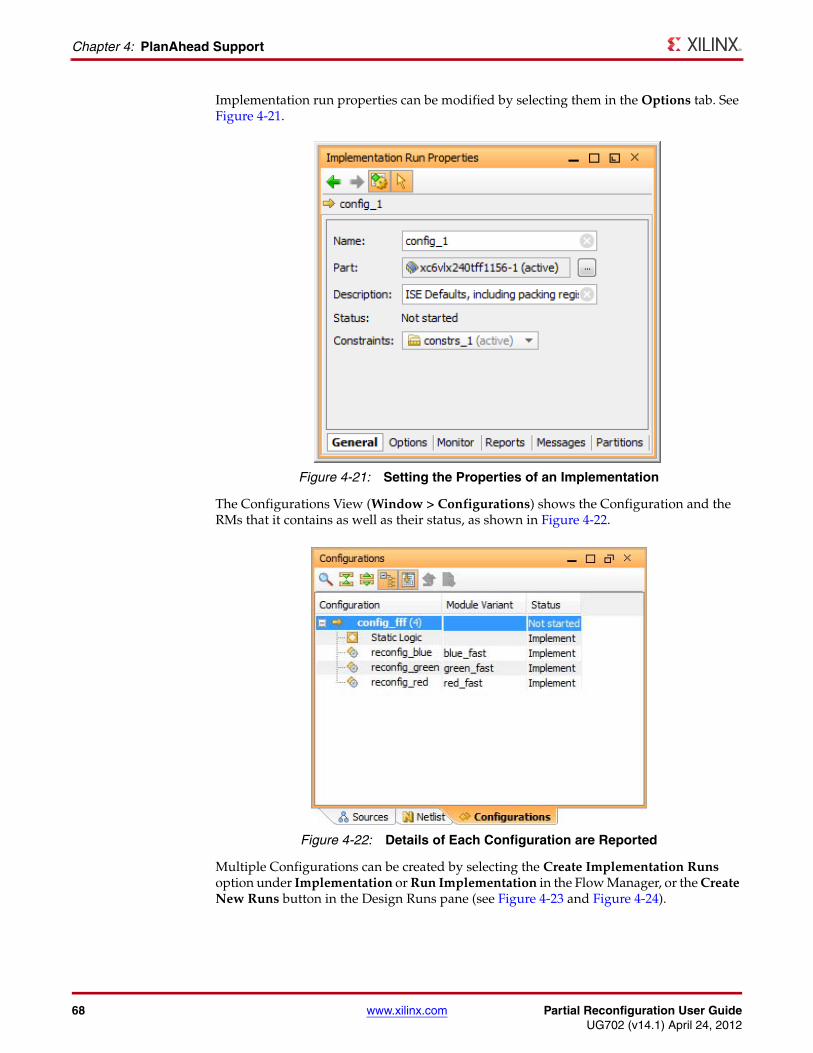
68 www.xilinx.com Partial Reconfiguration User GuideUG702 (v14.1) April 24, 2012
Chapter 4: PlanAhead Support
Implementation run properties can be modified by selecting them in the Options tab. See Figure 4-21.
The Configurations View (Window > Configurations) shows the Configuration and the RMs that it contains as well as their status, as shown in Figure 4-22.
Multiple Configurations can be created by selecting the Create Implementation Runs option under Implementation or Run Implementation in the Flow Manager, or the Create New Runs button in the Design Runs pane (see Figure 4-23 and Figure 4-24).
X-Ref Target - Figure 4-21
Figure 4-21: Setting the Properties of an Implementation
X-Ref Target - Figure 4-22
Figure 4-22: Details of Each Configuration are Reported
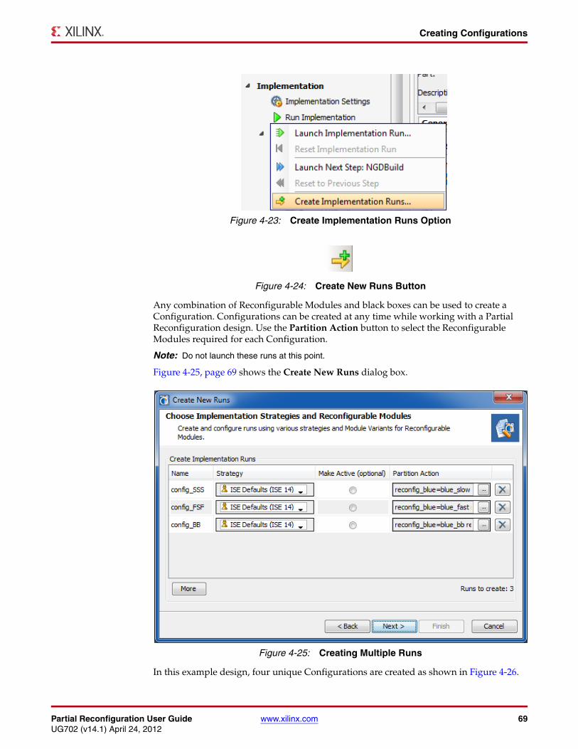
Partial Reconfiguration User Guide www.xilinx.com 69UG702 (v14.1) April 24, 2012
Creating Configurations
Any combination of Reconfigurable Modules and black boxes can be used to create a Configuration. Configurations can be created at any time while working with a Partial Reconfiguration design. Use the Partition Action button to select the Reconfigurable Modules required for each Configuration.
Note: Do not launch these runs at this point.
Figure 4-25, page 69 shows the Create New Runs dialog box.
In this example design, four unique Configurations are created as shown in Figure 4-26.
X-Ref Target - Figure 4-23
Figure 4-23: Create Implementation Runs Option
X-Ref Target - Figure 4-24
Figure 4-24: Create New Runs Button
X-Ref Target - Figure 4-25
Figure 4-25: Creating Multiple Runs
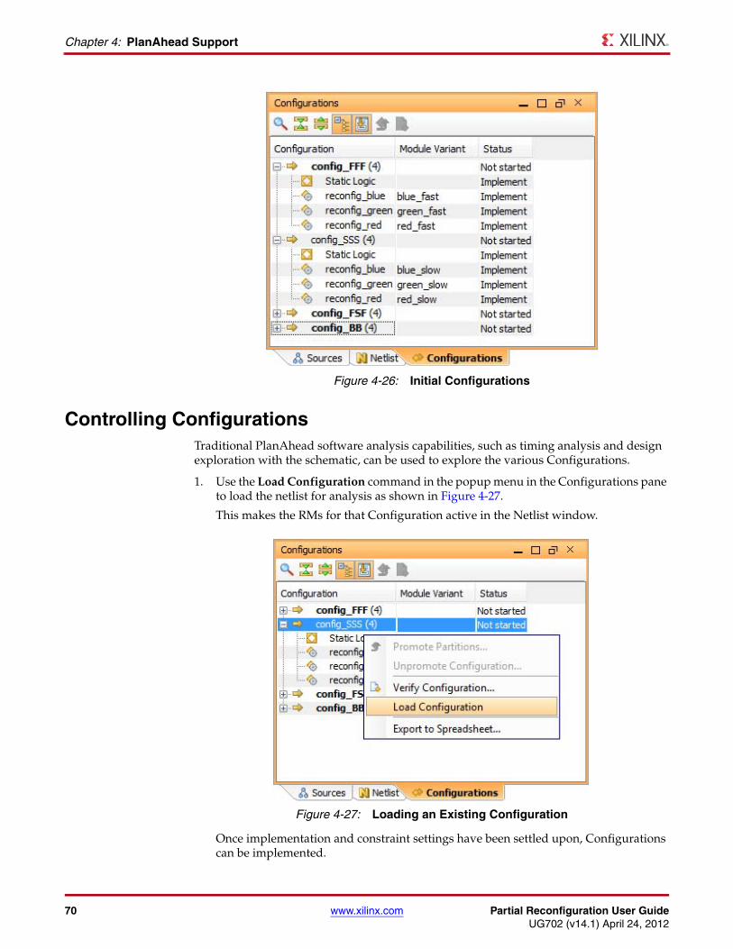
70 www.xilinx.com Partial Reconfiguration User GuideUG702 (v14.1) April 24, 2012
Chapter 4: PlanAhead Support
Controlling ConfigurationsTraditional PlanAhead software analysis capabilities, such as timing analysis and design exploration with the schematic, can be used to explore the various Configurations.
1. Use the Load Configuration command in the popup menu in the Configurations pane to load the netlist for analysis as shown in Figure 4-27.
This makes the RMs for that Configuration active in the Netlist window.
Once implementation and constraint settings have been settled upon, Configurations can be implemented.
X-Ref Target - Figure 4-26
Figure 4-26: Initial Configurations
X-Ref Target - Figure 4-27
Figure 4-27: Loading an Existing Configuration
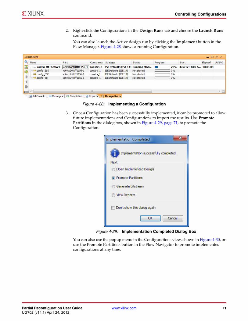
Partial Reconfiguration User Guide www.xilinx.com 71UG702 (v14.1) April 24, 2012
Controlling Configurations
2. Right-click the Configurations in the Design Runs tab and choose the Launch Runs command.
You can also launch the Active design run by clicking the Implement button in the Flow Manager. Figure 4-28 shows a running Configuration.
3. Once a Configuration has been successfully implemented, it can be promoted to allow future implementations and Configurations to import the results. Use Promote Partitions in the dialog box, shown in Figure 4-29, page 71, to promote the Configuration.
You can also use the popup menu in the Configurations view, shown in Figure 4-30, or use the Promote Partitions button in the Flow Navigator to promote implemented configurations at any time.
X-Ref Target - Figure 4-28
Figure 4-28: Implementing a Configuration
X-Ref Target - Figure 4-29
Figure 4-29: Implementation Completed Dialog Box
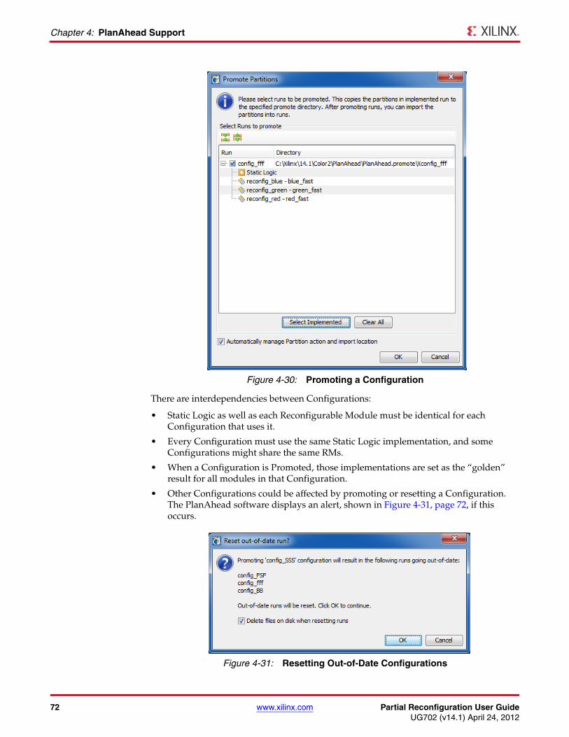
72 www.xilinx.com Partial Reconfiguration User GuideUG702 (v14.1) April 24, 2012
Chapter 4: PlanAhead Support
There are interdependencies between Configurations:
• Static Logic as well as each Reconfigurable Module must be identical for each Configuration that uses it.
• Every Configuration must use the same Static Logic implementation, and some Configurations might share the same RMs.
• When a Configuration is Promoted, those implementations are set as the “golden” result for all modules in that Configuration.
• Other Configurations could be affected by promoting or resetting a Configuration. The PlanAhead software displays an alert, shown in Figure 4-31, page 72, if this occurs.
X-Ref Target - Figure 4-30
Figure 4-30: Promoting a Configuration
X-Ref Target - Figure 4-31
Figure 4-31: Resetting Out-of-Date Configurations
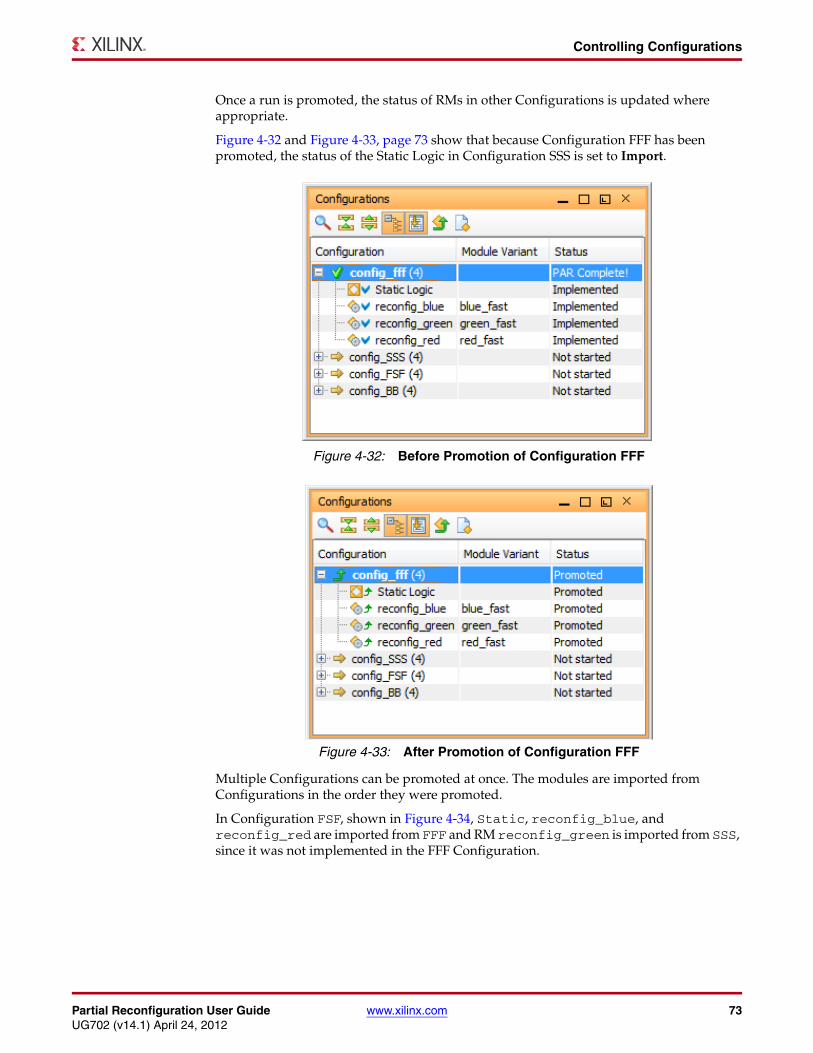
Partial Reconfiguration User Guide www.xilinx.com 73UG702 (v14.1) April 24, 2012
Controlling Configurations
Once a run is promoted, the status of RMs in other Configurations is updated where appropriate.
Figure 4-32 and Figure 4-33, page 73 show that because Configuration FFF has been promoted, the status of the Static Logic in Configuration SSS is set to Import.
Multiple Configurations can be promoted at once. The modules are imported from Configurations in the order they were promoted.
In Configuration FSF, shown in Figure 4-34, Static, reconfig_blue, and reconfig_red are imported from FFF and RM reconfig_green is imported from SSS, since it was not implemented in the FFF Configuration.
X-Ref Target - Figure 4-32
Figure 4-32: Before Promotion of Configuration FFF
X-Ref Target - Figure 4-33
Figure 4-33: After Promotion of Configuration FFF
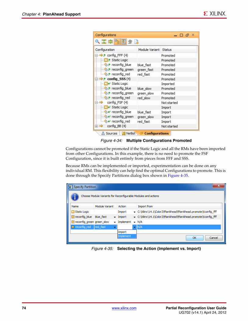
74 www.xilinx.com Partial Reconfiguration User GuideUG702 (v14.1) April 24, 2012
Chapter 4: PlanAhead Support
Configurations cannot be promoted if the Static Logic and all the RMs have been imported from other Configurations. In this example, there is no need to promote the FSF Configuration, since it is built entirely from pieces from FFF and SSS.
Because RMs can be implemented or imported, experimentation can be done on any individual RM. This flexibility can help find the optimal Configurations to promote. This is done through the Specify Partitions dialog box shown in Figure 4-35.
X-Ref Target - Figure 4-34
Figure 4-34: Multiple Configurations Promoted
X-Ref Target - Figure 4-35
Figure 4-35: Selecting the Action (Implement vs. Import)
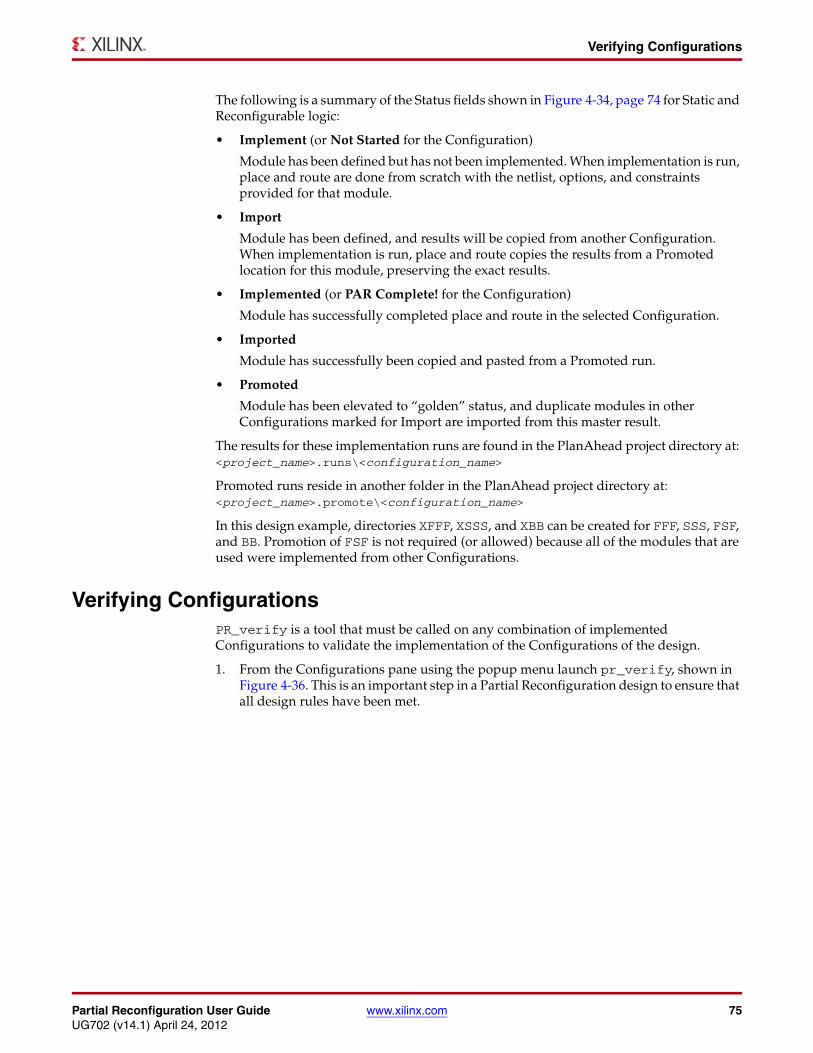
Partial Reconfiguration User Guide www.xilinx.com 75UG702 (v14.1) April 24, 2012
Verifying Configurations
The following is a summary of the Status fields shown in Figure 4-34, page 74 for Static and Reconfigurable logic:
• Implement (or Not Started for the Configuration)
Module has been defined but has not been implemented. When implementation is run, place and route are done from scratch with the netlist, options, and constraints provided for that module.
• Import
Module has been defined, and results will be copied from another Configuration. When implementation is run, place and route copies the results from a Promoted location for this module, preserving the exact results.
• Implemented (or PAR Complete! for the Configuration)
Module has successfully completed place and route in the selected Configuration.
• Imported
Module has successfully been copied and pasted from a Promoted run.
• Promoted
Module has been elevated to “golden” status, and duplicate modules in other Configurations marked for Import are imported from this master result.
The results for these implementation runs are found in the PlanAhead project directory at: <project_name>.runs\<configuration_name>
Promoted runs reside in another folder in the PlanAhead project directory at: <project_name>.promote\<configuration_name>
In this design example, directories XFFF, XSSS, and XBB can be created for FFF, SSS, FSF, and BB. Promotion of FSF is not required (or allowed) because all of the modules that are used were implemented from other Configurations.
Verifying ConfigurationsPR_verify is a tool that must be called on any combination of implemented Configurations to validate the implementation of the Configurations of the design.
1. From the Configurations pane using the popup menu launch pr_verify, shown in Figure 4-36. This is an important step in a Partial Reconfiguration design to ensure that all design rules have been met.
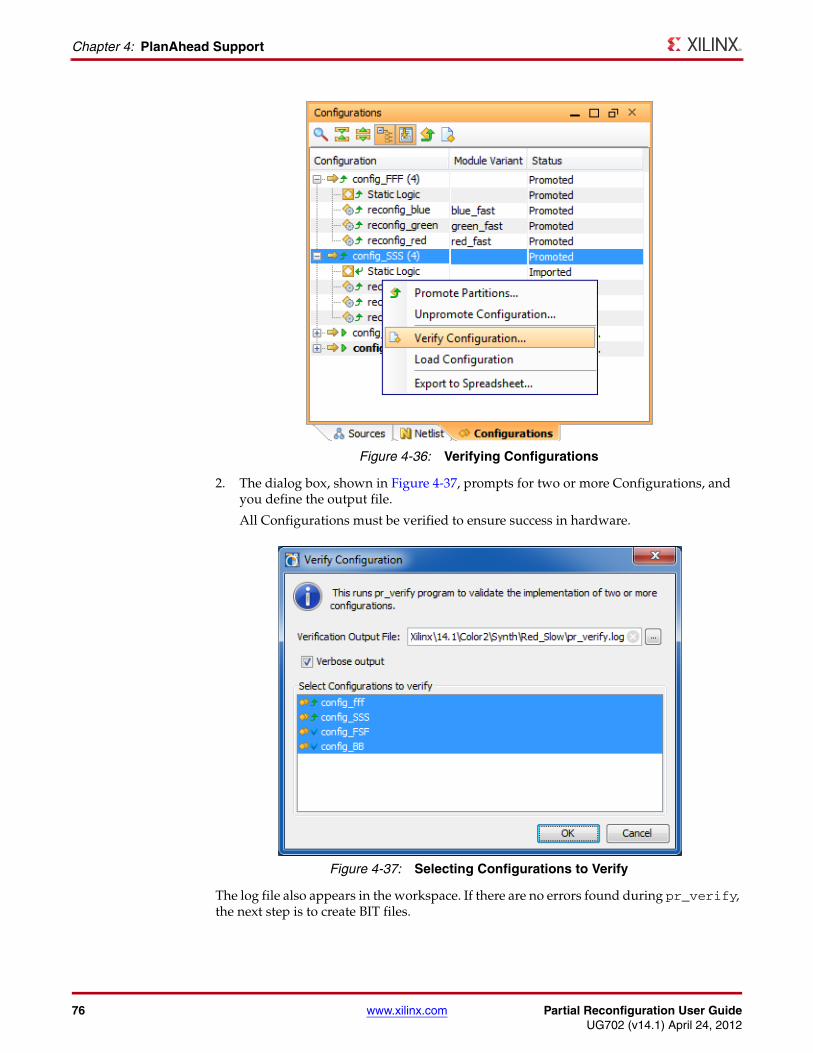
76 www.xilinx.com Partial Reconfiguration User GuideUG702 (v14.1) April 24, 2012
Chapter 4: PlanAhead Support
2. The dialog box, shown in Figure 4-37, prompts for two or more Configurations, and you define the output file.
All Configurations must be verified to ensure success in hardware.
The log file also appears in the workspace. If there are no errors found during pr_verify, the next step is to create BIT files.
X-Ref Target - Figure 4-36
Figure 4-36: Verifying Configurations
X-Ref Target - Figure 4-37
Figure 4-37: Selecting Configurations to Verify
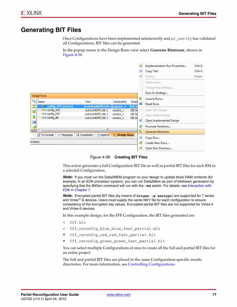
Partial Reconfiguration User Guide www.xilinx.com 77UG702 (v14.1) April 24, 2012
Generating BIT Files
Generating BIT FilesOnce Configurations have been implemented satisfactorily and pr_verify has validated all Configurations, BIT files can be generated.
In the popup menu in the Design Runs view select Generate Bitstream, shown in Figure 4-38.
This action generates a full Configuration BIT file as well as partial BIT files for each RM in a selected Configuration.
Note: If you must run the Data2MEM program on your design to update block RAM contents (for example, in an EDK processor system), you can run Data2Mem as part of bitstream generation by specifying that the BitGen command will run with the -bd switch. For details, see Interaction with EDK in Chapter 7.
Note: Encrypted partial BIT files (by means of bitgen -g encrypt) are supported for 7 series and Virtex®-6 devices. Users must supply the same NKY file for each configuration to ensure consistency of the encryption key values. Encrypted partial BIT files are not supported for Virtex-4 and Virtex-5 devices.
In this example design, for the FFF Configuration, the BIT files generated are:
• fff.bit
• fff_reconfig_blue_blue_fast_partial.bit
• fff_reconfig_red_red_fast_partial.bit
• fff_reconfig_green_green_fast_partial.bit
You can select multiple Configurations at once to create all the full and partial BIT files for an entire project.
The full and partial BIT files are placed in the same Configuration-specific results directories. For more information, see Controlling Configurations.
X-Ref Target - Figure 4-38
Figure 4-38: Creating BIT Files
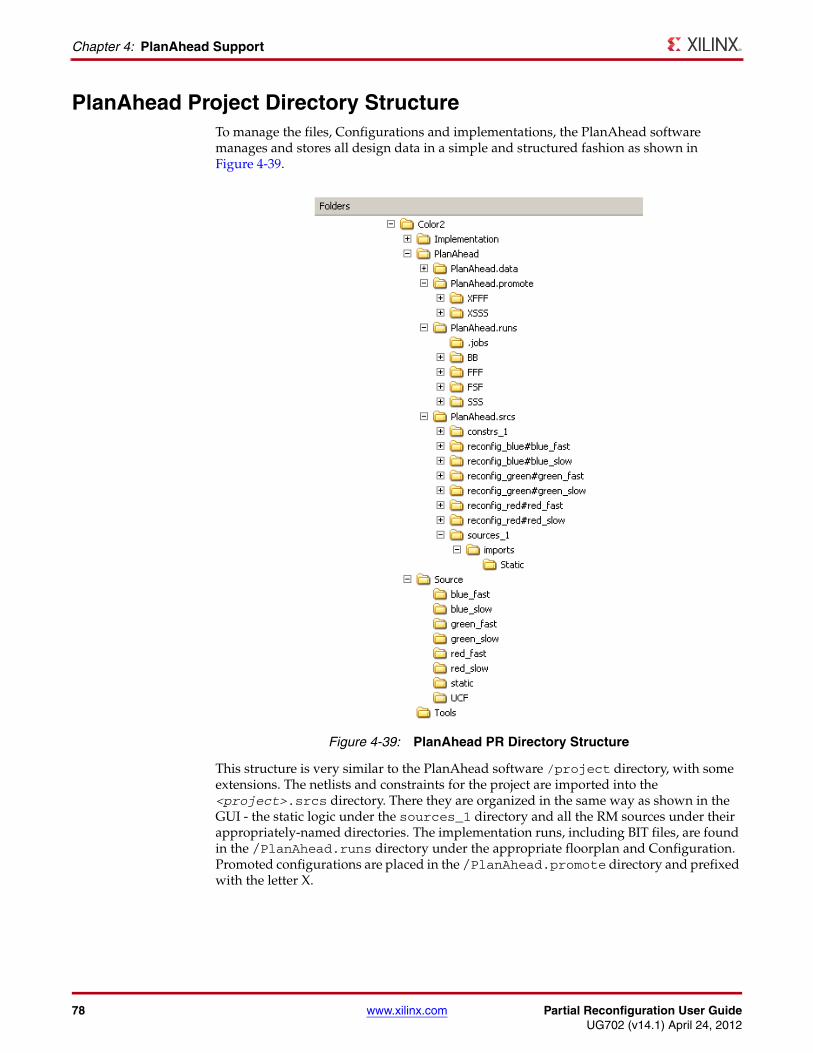
78 www.xilinx.com Partial Reconfiguration User GuideUG702 (v14.1) April 24, 2012
Chapter 4: PlanAhead Support
PlanAhead Project Directory StructureTo manage the files, Configurations and implementations, the PlanAhead software manages and stores all design data in a simple and structured fashion as shown in Figure 4-39.
This structure is very similar to the PlanAhead software /project directory, with some extensions. The netlists and constraints for the project are imported into the <project>.srcs directory. There they are organized in the same way as shown in the GUI - the static logic under the sources_1 directory and all the RM sources under their appropriately-named directories. The implementation runs, including BIT files, are found in the /PlanAhead.runs directory under the appropriate floorplan and Configuration. Promoted configurations are placed in the /PlanAhead.promote directory and prefixed with the letter X.
X-Ref Target - Figure 4-39
Figure 4-39: PlanAhead PR Directory Structure
Partial Reconfiguration User Guide www.xilinx.com 79UG702 (v14.1) April 24, 2012
Chapter 5
Command Line Scripting
This chapter gives instructions and recommendations on how to automate the flow through the toolset, without the use of a GUI.
Xilinx® provides a set of example Tcl scripts to define and implement a Partition-based Partial Reconfiguration Design. These scripts work for a general flow and provide a template that can be modified for custom flows.
A Tcl shell must be available to run these scripts. Many Linux distributions have Tcl installed in the /usr/bin directory, which is found by default. If a Tcl shell is not installed, you can download one for free from http://www.activestate.com/activetcl. The scripts in this guide have been tested with Tcl version 8.4.
Tcl Scripts• xpartition.tcl
Defines and implements a Partition-based Partial Reconfiguration Design. It calls three other Tcl scripts to perform these functions. Xilinx® recommends that this script be used to run the complete flow.
• gen_xp.tcl
Creates and/or modifies the necessary Partition files for each project. It is called by the xpartition.tcl script.
• implement.tcl
Implements a Partition-based PR Configuration. It is called from the xpartition.tcl script.
• export.tcl
Exports the necessary files to import a Partition into future runs. It is called from the xpartition.tcl script.
The xpartition.tcl file takes a data.tcl file as an argument. The data.tcl file contains Partition definitions, Configurations, and options for implementation. This file allows for modification of the design and its options without changing the Tcl scripts.
Following is a sample command line calling the Tcl scripts. This is launched from the root folder of a PR project as described in Chapter 3, Software Tools Flow.
xtclsh .\Tools\xpartition.tcl .\Tools\data.tcl
80 www.xilinx.com Partial Reconfiguration User GuideUG702 (v14.1) April 24, 2012
Chapter 5: Command Line Scripting
Data.tcl FormatThe data.tcl file is divided into three main sections. The data.tcl uses # to mark comments outside of list or array declarations. Members of lists and arrays must be deleted or commented outside of the list or array, to have them be ignored.
In the Color2 sample design there are several versions of the data file provided. They can be used interchangeably in the xtclsh command shown above. These data files are provided as reference and can be modified to meet your needs.
• data.tcl - Runs synthesis and implementation and should be used when starting the scripted flow from scratch.
• data_synth.tcl - Runs synthesis only and is useful when running synthesis from the command line and implementation using the PlanAhead software.
• data_impl.tcl - Runs implementation only and is useful when synthesis has already been run but small changes are needed for implementation, like adjusting a timing or physical constraint.
Section 1: Set Project OptionsSection 1: Set Project Options lets you set variables, including environment variables, part, constraints file, Partitions, and Reconfigurable Modules.
# 1:environment variables for all configurations
Define any environment variables that are required for implementation here using the format below. These variables are used for all Configurations.
set ::env(VARIABLE) value
# 1:environment variables for all configurationsset ::env(XIL_TIMING_ALLOW_IMPOSSIBLE) 1
# 2:part definitionset PART xc5vlx50t-3-ff1136
# 3:constraints fileset UCF ../../Source/UCF/top_ml505.ucf
# 4:Partition names# These names must match the actual instance names in the designset TOP_PART /topset RED_PART ${TOP_PART}/reconfig_redset GREEN_PART ${TOP_PART}/reconfig_greenset BLUE_PART ${TOP_PART}/reconfig_blue
# 5:RM names set RED_FAST Red_Fastset RED_SLOW Red_Slowset RED_BB Red_Blankset GREEN_FAST Green_Fastset GREEN_SLOW Green_Slowset GREEN_BB Green_Blankset BLUE_FAST Blue_Fastset BLUE_SLOW Blue_Slowset BLUE_BB Blue_Blankset STATIC Static
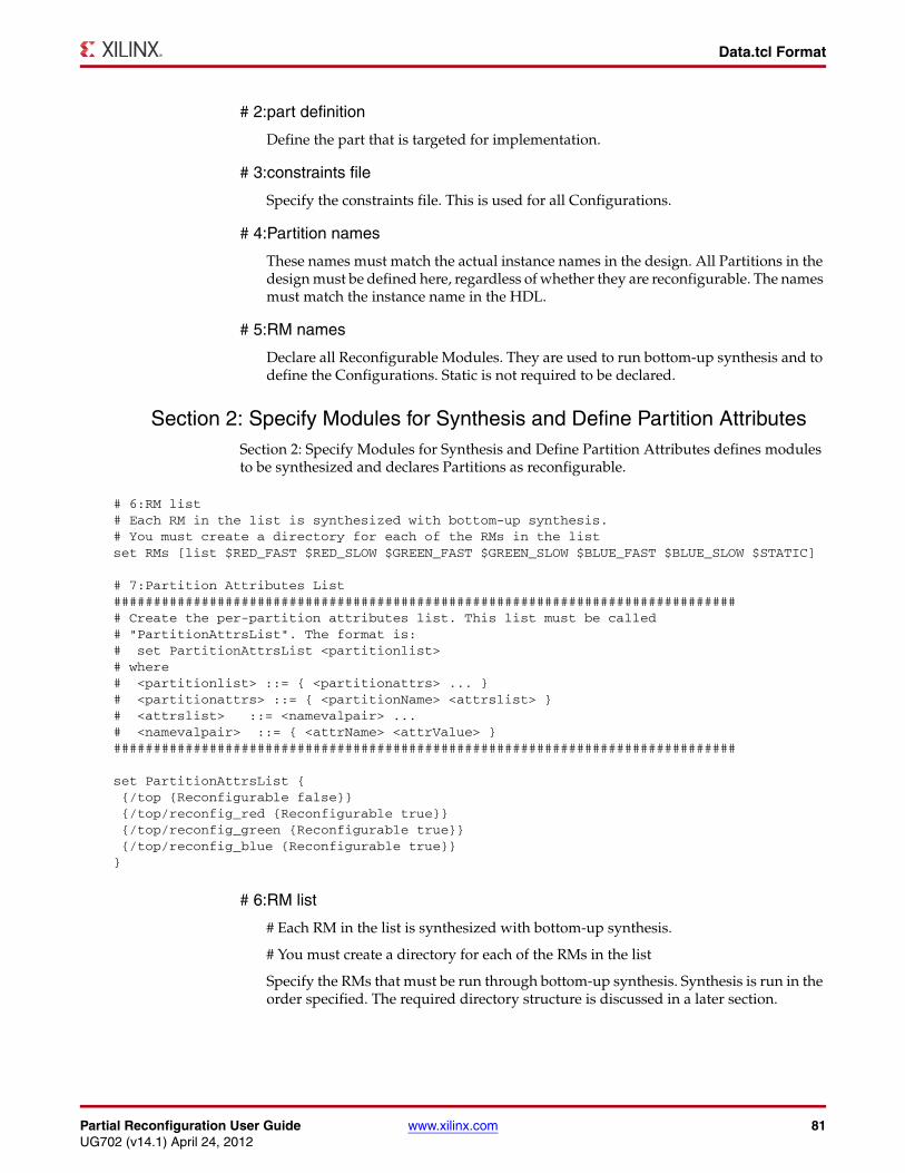
Partial Reconfiguration User Guide www.xilinx.com 81UG702 (v14.1) April 24, 2012
Data.tcl Format
# 2:part definition
Define the part that is targeted for implementation.
# 3:constraints file
Specify the constraints file. This is used for all Configurations.
# 4:Partition names
These names must match the actual instance names in the design. All Partitions in the design must be defined here, regardless of whether they are reconfigurable. The names must match the instance name in the HDL.
# 5:RM names
Declare all Reconfigurable Modules. They are used to run bottom-up synthesis and to define the Configurations. Static is not required to be declared.
Section 2: Specify Modules for Synthesis and Define Partition AttributesSection 2: Specify Modules for Synthesis and Define Partition Attributes defines modules to be synthesized and declares Partitions as reconfigurable.
# 6:RM list
# Each RM in the list is synthesized with bottom-up synthesis.
# You must create a directory for each of the RMs in the list
Specify the RMs that must be run through bottom-up synthesis. Synthesis is run in the order specified. The required directory structure is discussed in a later section.
# 6:RM list# Each RM in the list is synthesized with bottom-up synthesis.# You must create a directory for each of the RMs in the listset RMs [list $RED_FAST $RED_SLOW $GREEN_FAST $GREEN_SLOW $BLUE_FAST $BLUE_SLOW $STATIC]
# 7:Partition Attributes List############################################################################### Create the per-partition attributes list. This list must be called # "PartitionAttrsList". The format is:# set PartitionAttrsList <partitionlist># where# <partitionlist> ::= { <partitionattrs> ... }# <partitionattrs> ::= { <partitionName> <attrslist> }# <attrslist> ::= <namevalpair> ...# <namevalpair> ::= { <attrName> <attrValue> }##############################################################################
set PartitionAttrsList { {/top {Reconfigurable false}} {/top/reconfig_red {Reconfigurable true}} {/top/reconfig_green {Reconfigurable true}} {/top/reconfig_blue {Reconfigurable true}}}
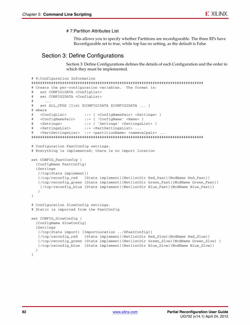
82 www.xilinx.com Partial Reconfiguration User GuideUG702 (v14.1) April 24, 2012
Chapter 5: Command Line Scripting
# 7:Partition Attributes List
This allows you to specify whether Partitions are reconfigurable. The three RPs have Reconfigurable set to true, while top has no setting, as the default is False.
Section 3: Define ConfigurationsSection 3: Define Configurations defines the details of each Configuration and the order in which they must be implemented.
# 8:Configuration Information############################################################################### Create the per-configuration variables. The format is:# set CONFIG1DATA <ConfigList># set CONFIG2DATA <ConfigList># ...# set ALL_CFGS [list $CONFIG1DATA $CONFIG2DATA ... ]# where# <ConfigList> ::= { <ConfigNamePair> <Settings> }# <ConfigNamePair> ::= { 'ConfigName' <Name> }# <Settings> ::= { 'Settings' <SettingsList> }# <SettingsList> ::= <PartSettingsList> ...# <PartSettingsList> ::= <partitionName> <namevalpair> ...##############################################################################
# Configuration FastConfig settings.# Everything is implemented; there is no import location
set CONFIG_FastConfig { {ConfigName FastConfig} {Settings {/top{State implement}} {/top/reconfig_red {State implement}{NetlistDir Red_Fast}{ModName Red_Fast}} {/top/reconfig_green {State implement}{NetlistDir Green_Fast}{ModName Green_Fast}} {/top/reconfig_blue {State implement}{NetlistDir Blue_Fast}{ModName Blue_Fast}} }}
# Configuration SlowConfig settings.# Static is imported from the FastConfig
set CONFIG_SlowConfig { {ConfigName SlowConfig} {Settings {/top{State import} {ImportLocation ../XFastConfig}} {/top/reconfig_red {State implement}{NetlistDir Red_Slow}{ModName Red_Slow}} {/top/reconfig_green {State implement}{NetlistDir Green_Slow}{ModName Green_Slow} } {/top/reconfig_blue {State implement}{NetlistDir Blue_Slow}{ModName Blue_Slow}} }}
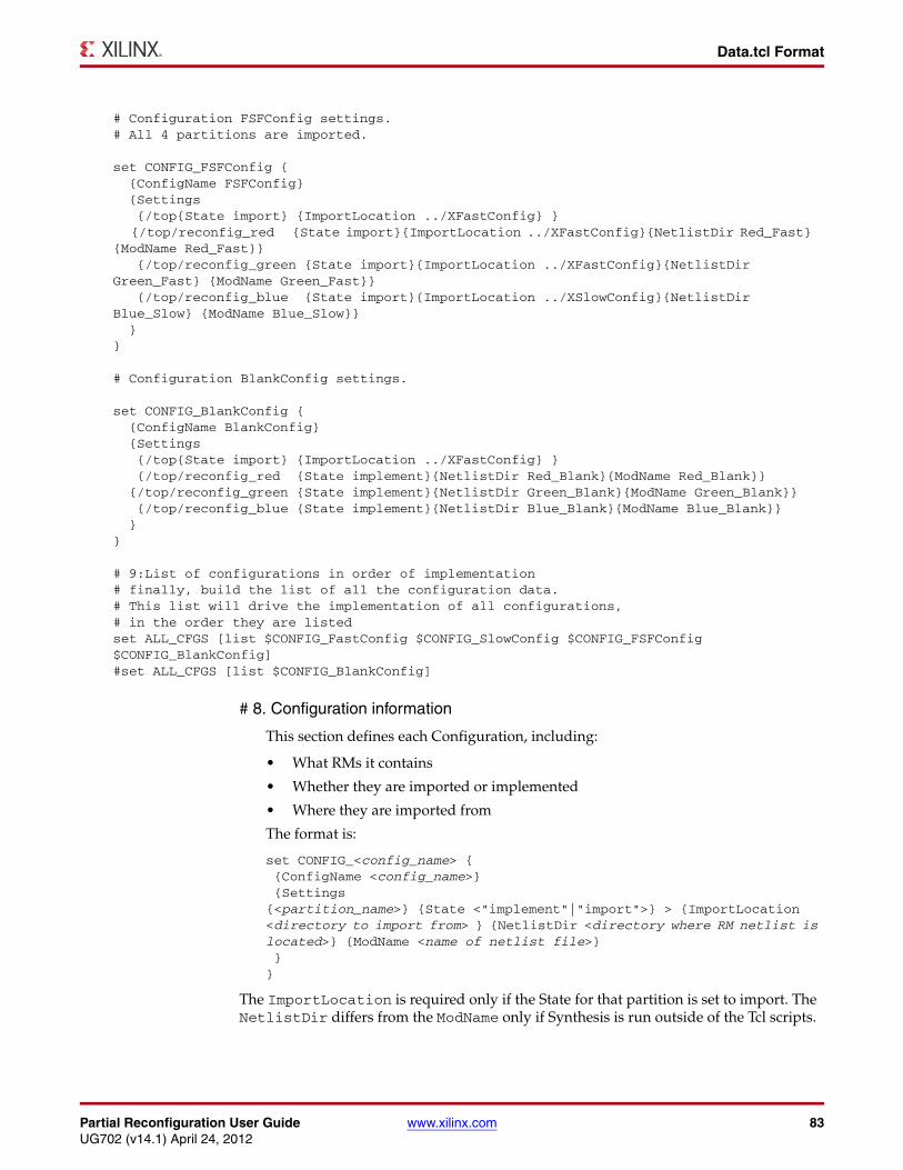
Partial Reconfiguration User Guide www.xilinx.com 83UG702 (v14.1) April 24, 2012
Data.tcl Format
# 8. Configuration information
This section defines each Configuration, including:
• What RMs it contains
• Whether they are imported or implemented
• Where they are imported from
The format is:
set CONFIG_<config_name> { {ConfigName <config_name>} {Settings{<partition_name>} {State <"implement"|"import">} > {ImportLocation <directory to import from> } {NetlistDir <directory where RM netlist is located>} {ModName <name of netlist file>} }}
The ImportLocation is required only if the State for that partition is set to import. The NetlistDir differs from the ModName only if Synthesis is run outside of the Tcl scripts.
# Configuration FSFConfig settings.# All 4 partitions are imported.
set CONFIG_FSFConfig { {ConfigName FSFConfig} {Settings {/top{State import} {ImportLocation ../XFastConfig} } {/top/reconfig_red {State import}{ImportLocation ../XFastConfig}{NetlistDir Red_Fast} {ModName Red_Fast}} {/top/reconfig_green {State import}{ImportLocation ../XFastConfig}{NetlistDir Green_Fast} {ModName Green_Fast}} {/top/reconfig_blue {State import}{ImportLocation ../XSlowConfig}{NetlistDir Blue_Slow} {ModName Blue_Slow}} }}
# Configuration BlankConfig settings.
set CONFIG_BlankConfig { {ConfigName BlankConfig} {Settings {/top{State import} {ImportLocation ../XFastConfig} } {/top/reconfig_red {State implement}{NetlistDir Red_Blank}{ModName Red_Blank}} {/top/reconfig_green {State implement}{NetlistDir Green_Blank}{ModName Green_Blank}} {/top/reconfig_blue {State implement}{NetlistDir Blue_Blank}{ModName Blue_Blank}} }}
# 9:List of configurations in order of implementation# finally, build the list of all the configuration data. # This list will drive the implementation of all configurations, # in the order they are listedset ALL_CFGS [list $CONFIG_FastConfig $CONFIG_SlowConfig $CONFIG_FSFConfig $CONFIG_BlankConfig]#set ALL_CFGS [list $CONFIG_BlankConfig]
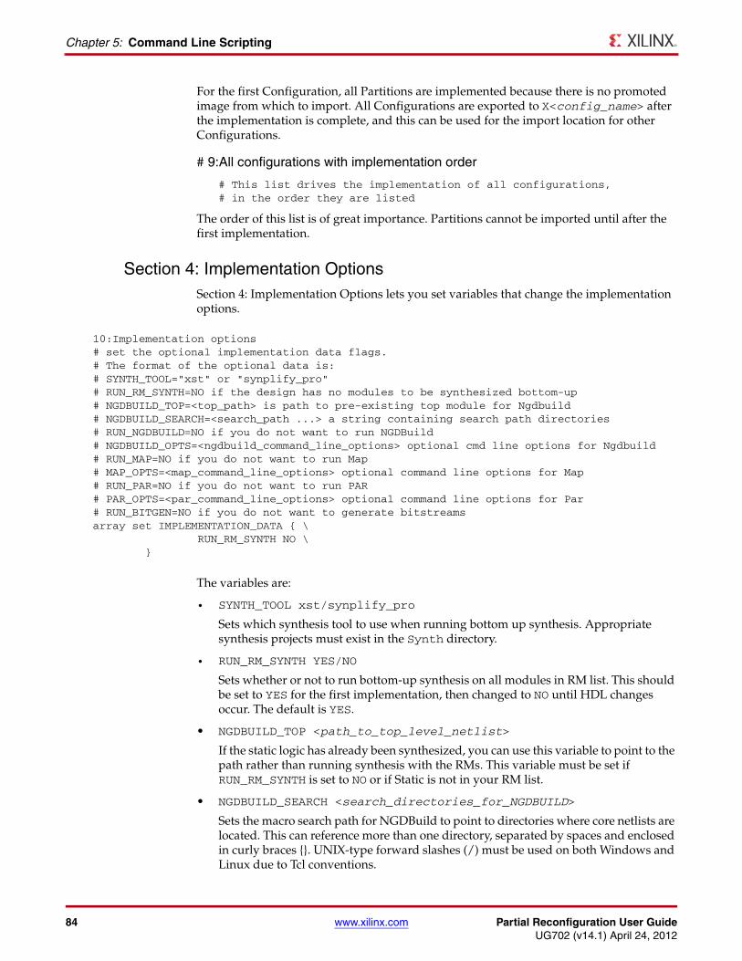
84 www.xilinx.com Partial Reconfiguration User GuideUG702 (v14.1) April 24, 2012
Chapter 5: Command Line Scripting
For the first Configuration, all Partitions are implemented because there is no promoted image from which to import. All Configurations are exported to X<config_name> after the implementation is complete, and this can be used for the import location for other Configurations.
# 9:All configurations with implementation order
# This list drives the implementation of all configurations, # in the order they are listed
The order of this list is of great importance. Partitions cannot be imported until after the first implementation.
Section 4: Implementation OptionsSection 4: Implementation Options lets you set variables that change the implementation options.
The variables are:
• SYNTH_TOOL xst/synplify_pro
Sets which synthesis tool to use when running bottom up synthesis. Appropriate synthesis projects must exist in the Synth directory.
• RUN_RM_SYNTH YES/NO
Sets whether or not to run bottom-up synthesis on all modules in RM list. This should be set to YES for the first implementation, then changed to NO until HDL changes occur. The default is YES.
• NGDBUILD_TOP <path_to_top_level_netlist>
If the static logic has already been synthesized, you can use this variable to point to the path rather than running synthesis with the RMs. This variable must be set if RUN_RM_SYNTH is set to NO or if Static is not in your RM list.
• NGDBUILD_SEARCH <search_directories_for_NGDBUILD>
Sets the macro search path for NGDBuild to point to directories where core netlists are located. This can reference more than one directory, separated by spaces and enclosed in curly braces {}. UNIX-type forward slashes (/) must be used on both Windows and Linux due to Tcl conventions.
10:Implementation options# set the optional implementation data flags. # The format of the optional data is:# SYNTH_TOOL="xst" or "synplify_pro"# RUN_RM_SYNTH=NO if the design has no modules to be synthesized bottom-up# NGDBUILD_TOP=<top_path> is path to pre-existing top module for Ngdbuild# NGDBUILD_SEARCH=<search_path ...> a string containing search path directories# RUN_NGDBUILD=NO if you do not want to run NGDBuild# NGDBUILD_OPTS=<ngdbuild_command_line_options> optional cmd line options for Ngdbuild# RUN_MAP=NO if you do not want to run Map# MAP_OPTS=<map_command_line_options> optional command line options for Map# RUN_PAR=NO if you do not want to run PAR# PAR_OPTS=<par_command_line_options> optional command line options for Par# RUN_BITGEN=NO if you do not want to generate bitstreamsarray set IMPLEMENTATION_DATA { \ RUN_RM_SYNTH NO \ }
Partial Reconfiguration User Guide www.xilinx.com 85UG702 (v14.1) April 24, 2012
Recommended Flow
• RUN_NGDBUILD YES/NO
Controls whether or not NGDBuild is run on all implementations.
• RUN_MAP YES/NO
Controls whether or not MAP is run on all implementations.
• RUN_PAR YES/NO
Controls whether or not PAR is run on all implementations.
• RUN_BITGEN YES/NO
Controls whether or not BitGen is run on all implementations.
Each implementation process may also have customized command line options. In the current software, customized options are set for all Configurations. To customize the command line tools, use the following three variables. The default for all three variables is to use the default implementation options. For more information on available command line options, see the Command Line Tools User Guide (UG628).
• NGDBUILD_OPTS <ngdbuild_options>
Optional NGDBuild command line options.
• MAP_OPTS <map_options>
Optional MAP command line options.
• PAR_OPTS <par_options>
Optional PAR command line options.
These options apply to implementation of all Configurations. To specify different command line options for a specific Configuration, use the –f option to select a command file in each directory. For example:
MAP_OPTS=<-f ./map.opt>
Looks for a map.opt file in the directory for each implementation and uses the options in it. For more information on the –f option, see the Command Line Tools User Guide (UG628).
Recommended FlowCurrently these scripts do not run pr_verify, although this is being investigated for a future release. You must still run pr_verify prior to configuring the device with the generated bitstreams.
The recommended method to incorporate this step into the flow is:
1. Run the complete flow, including bitgen, using the Tcl scripts.
2. Run the pr_verify command line prior to configuring the device. If the log reports PASS, you are safe to use the generated bitstreams.
For more information on running pr_verify, see Verifying Configurations in Chapter 4.
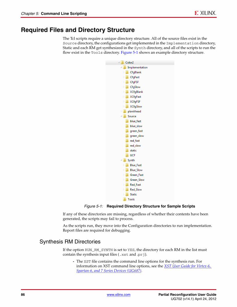
86 www.xilinx.com Partial Reconfiguration User GuideUG702 (v14.1) April 24, 2012
Chapter 5: Command Line Scripting
Required Files and Directory StructureThe Tcl scripts require a unique directory structure. All of the source files exist in the Source directory, the configurations get implemented in the Implementation directory, Static and each RM get synthesized in the Synth directory, and all of the scripts to run the flow exist in the Tools directory. Figure 5-1 shows an example directory structure.
If any of these directories are missing, regardless of whether their contents have been generated, the scripts may fail to process.
As the scripts run, they move into the Configuration directories to run implementation. Report files are required for debugging.
Synthesis RM DirectoriesIf the option RUN_RM_SYNTH is set to YES, the directory for each RM in the list must contain the synthesis input files (.xst and .prj).
- The XST file contains the command line options for the synthesis run. For information on XST command line options, see the XST User Guide for Virtex-6, Spartan-6, and 7 Series Devices (UG687).
X-Ref Target - Figure 5-1
Figure 5-1: Required Directory Structure for Sample Scripts
Partial Reconfiguration User Guide www.xilinx.com 87UG702 (v14.1) April 24, 2012
Required Files and Directory Structure
The following code is an example XST file.
run-ifn red.prj-ifmt mixed-ofn red-ofmt NGC-p xc5vlx50t-3-ff1136-top red-opt_mode Speed-opt_level 1-power NO-iuc NO-keep_hierarchy NO-netlist_hierarchy as_optimized-rtlview Yes-glob_opt AllClockNets-read_cores YES-write_timing_constraints NO-hierarchy_separator /-bus_delimiter <>-case maintain-slice_utilization_ratio 100-bram_utilization_ratio 100-dsp_utilization_ratio 100-reduce_control_sets off-verilog2001 YES-fsm_extract YES -fsm_encoding Auto-safe_implementation No-fsm_style lut
The XST file specifies the appropriate PRJ file as the input file. The PRJ file contains all the HDL files for an RM as well as the language and library to into which to compile the source. For example:
verilog work "../../Source/red_fast/led_fast.v"verilog work "../../Source/red_fast/red_fast.v"
Examples of both the .xst and .prj files can also be seen in theXST User Guide for Virtex-6, Spartan-6, and 7 Series Devices (UG687), or generated from the ISE® Design Suite.
In the example, the required directories are Red_Fast, Red_Slow, Red_Blank, Green_Fast, Green_Slow, Green_Blank, Blue_Fast, Blue_Slow, Blue_Blank and Static. If the NGDBUILD_TOP variable is used and $STATIC is removed from the RM list, the /Static directory is not required.
If the option RUN_RM_SYNTH is set to NO, the directory for each RM must contain the netlist for each module.
Configuration DirectoriesThese directories do not require any specific content, but must be created for implementation to run. In the example above, they are the CfgFast, CfgSlow, CfgFSF, and CfgBlank directories.

88 www.xilinx.com Partial Reconfiguration User GuideUG702 (v14.1) April 24, 2012
Chapter 5: Command Line Scripting
Export DirectoriesExport directories are created by the script to hold Configurations which have completed implementation. The names are based on the Configuration name (X<config_name>) and in the example are XCfgFast, XCfgSlow, XCfgFSF, and XCfgBlank. The files in these directories are overwritten each time the scripts are run. To save runs for analysis or comparison, save copies in a new location.
Partial Reconfiguration User Guide www.xilinx.com 89UG702 (v14.1) April 24, 2012
Chapter 6
Configuring the FPGA Device
This chapter describes the system design considerations when configuring the FPGA device with a partial BIT file, as well as architectural features in the FPGA that facilitate Partial Reconfiguration.
Because most aspects of Partial Reconfiguration are no different than standard full configuration, this section concentrates on the details that are unique to PR.
Any of the following configuration ports can be used to load the partial bitstream: SelectMAP, Serial, JTAG, or ICAP (Internal Configuration Access Port).
To use SelectMAP or Serial modes for loading a partial BIT file, these pins must be reserved for use after the initial device configuration. This is achieved by using the UCF constraint CONFIG_MODE (only needed to select a width of 16 or 32) and the bitgen -g persist option.
Partial bitstreams contain all the configuration commands and data necessary for Partial Reconfiguration. The task of loading a partial bitstream into an FPGA does not require knowledge of the physical location of the RM because configuration frame addressing information is included in the partial bitstream. A partial bitstream cannot be sent to the wrong part of the FPGA device.
A Partial Reconfiguration controller retrieves the partial bitstream from nonvolatile memory, then delivers it to a configuration port. The Partial Reconfiguration control logic can either reside in an external device (for example a processor) or in the fabric of the FPGA device to be reconfigured. A user-designed internal PR controller loads partial bitstreams through the ICAP interface. As with any other logic in the static design, the internal Partial Reconfiguration control circuitry operates without interruption throughout the Partial Reconfiguration process.
Internal configuration can consist of either a custom state machine, or an embedded processor such as MicroBlaze™ processor or PowerPC® 405 processor (PPC405).
As an aid in debugging Partial Reconfiguration designs and PR control logic, the Xilinx® iMPACT™ tool can be used to load full and partial bitstreams into an FPGA device by means of the JTAG port.
For more information on loading a bitstream into the configuration ports, see the ”Configuration Interfaces” chapter in:
• Virtex-4 FPGA Configuration User Guide (UG071)
• Virtex-5 FPGA Configuration User Guide (UG191)
• Virtex-6 FPGA Configuration User Guide (UG360)
• 7 Series FPGAs Configuration User Guide (UG470)
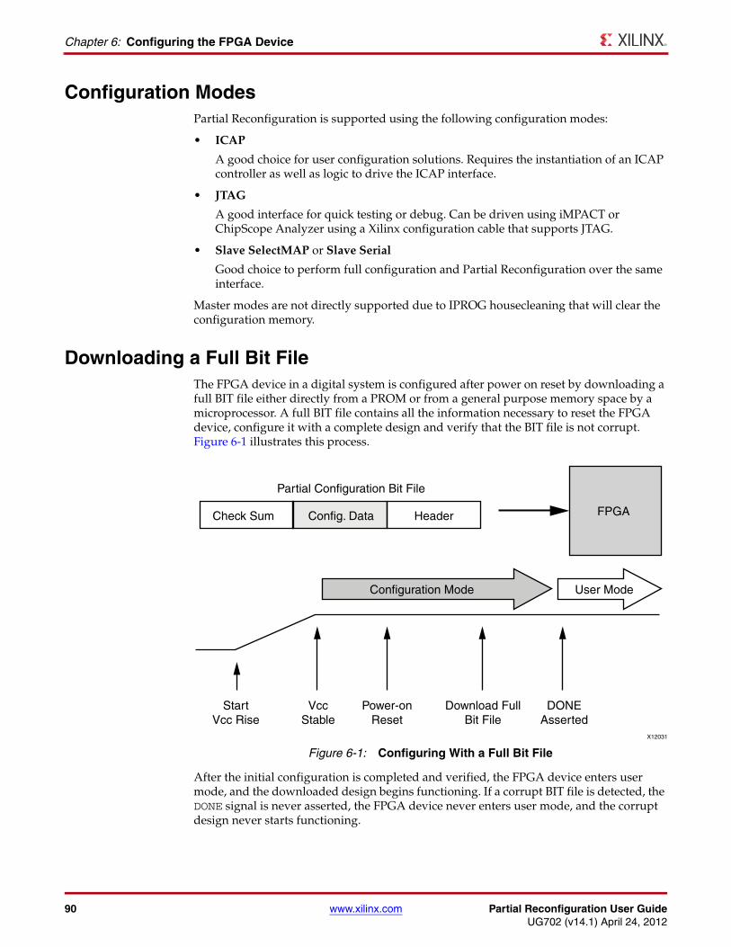
90 www.xilinx.com Partial Reconfiguration User GuideUG702 (v14.1) April 24, 2012
Chapter 6: Configuring the FPGA Device
Configuration ModesPartial Reconfiguration is supported using the following configuration modes:
• ICAP
A good choice for user configuration solutions. Requires the instantiation of an ICAP controller as well as logic to drive the ICAP interface.
• JTAG
A good interface for quick testing or debug. Can be driven using iMPACT or ChipScope Analyzer using a Xilinx configuration cable that supports JTAG.
• Slave SelectMAP or Slave Serial
Good choice to perform full configuration and Partial Reconfiguration over the same interface.
Master modes are not directly supported due to IPROG housecleaning that will clear the configuration memory.
Downloading a Full Bit FileThe FPGA device in a digital system is configured after power on reset by downloading a full BIT file either directly from a PROM or from a general purpose memory space by a microprocessor. A full BIT file contains all the information necessary to reset the FPGA device, configure it with a complete design and verify that the BIT file is not corrupt. Figure 6-1 illustrates this process.
After the initial configuration is completed and verified, the FPGA device enters user mode, and the downloaded design begins functioning. If a corrupt BIT file is detected, the DONE signal is never asserted, the FPGA device never enters user mode, and the corrupt design never starts functioning.
X-Ref Target - Figure 6-1
Figure 6-1: Configuring With a Full Bit File
X12031
Partial Configuration Bit File
Config. Data HeaderCheck Sum
Configuration Mode User Mode
FPGA
StartVcc Rise
VccStable
Power-onReset
Download FullBit File
DONEAsserted
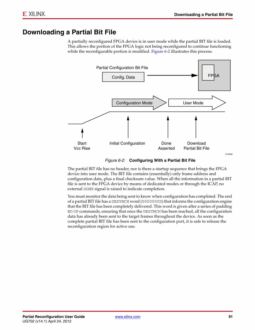
Partial Reconfiguration User Guide www.xilinx.com 91UG702 (v14.1) April 24, 2012
Downloading a Partial Bit File
Downloading a Partial Bit FileA partially reconfigured FPGA device is in user mode while the partial BIT file is loaded. This allows the portion of the FPGA logic not being reconfigured to continue functioning while the reconfigurable portion is modified. Figure 6-2 illustrates this process.
The partial BIT file has no header, nor is there a startup sequence that brings the FPGA device into user mode. The BIT file contains (essentially) only frame address and configuration data, plus a final checksum value. When all the information in a partial BIT file is sent to the FPGA device by means of dedicated modes or through the ICAP, no external DONE signal is raised to indicate completion.
You must monitor the data being sent to know when configuration has completed. The end of a partial BIT file has a DESYNCH word (0000000D) that informs the configuration engine that the BIT file has been completely delivered. This word is given after a series of padding NO OP commands, ensuring that once the DESYNCH has been reached, all the configuration data has already been sent to the target frames throughout the device. As soon as the complete partial BIT file has been sent to the configuration port, it is safe to release the reconfiguration region for active use.
X-Ref Target - Figure 6-2
Figure 6-2: Configuring With a Partial Bit File
X12032
Partial Configuration Bit File
Config. Data
Configuration Mode User Mode
FPGA
StartVcc Rise
Initial Configuration DoneAsserted
DownloadPartial Bit File
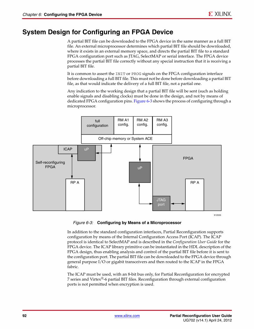
92 www.xilinx.com Partial Reconfiguration User GuideUG702 (v14.1) April 24, 2012
Chapter 6: Configuring the FPGA Device
System Design for Configuring an FPGA DeviceA partial BIT file can be downloaded to the FPGA device in the same manner as a full BIT file. An external microprocessor determines which partial BIT file should be downloaded, where it exists in an external memory space, and directs the partial BIT file to a standard FPGA configuration port such as JTAG, SelectMAP or serial interface. The FPGA device processes the partial BIT file correctly without any special instruction that it is receiving a partial BIT file.
It is common to assert the INIT or PROG signals on the FPGA configuration interface before downloading a full BIT file. This must not be done before downloading a partial BIT file, as that would indicate the delivery of a full BIT file, not a partial one.
Any indication to the working design that a partial BIT file will be sent (such as holding enable signals and disabling clocks) must be done in the design, and not by means of dedicated FPGA configuration pins. Figure 6-3 shows the process of configuring through a microprocessor.
In addition to the standard configuration interfaces, Partial Reconfiguration supports configuration by means of the Internal Configuration Access Port (ICAP). The ICAP protocol is identical to SelectMAP and is described in the Configuration User Guide for the FPGA device. The ICAP library primitive can be instantiated in the HDL description of the FPGA design, thus enabling analysis and control of the partial BIT file before it is sent to the configuration port. The partial BIT file can be downloaded to the FPGA device through general purpose I/O or gigabit transceivers and then routed to the ICAP in the FPGA fabric.
The ICAP must be used, with an 8-bit bus only, for Partial Reconfiguration for encrypted 7 series and Virtex®-6 partial BIT files. Reconfiguration through external configuration ports is not permitted when encryption is used.
X-Ref Target - Figure 6-3
Figure 6-3: Configuring by Means of a Microprocessor
X12033
Self-reconfiguringFPGA
ICAP uP
uP
RP A
JTAGport
RP A
FPGA
fullconfiguration
RM A1config.
RM A2config.
RM A3config.
Off-chip memory or System ACE
Partial Reconfiguration User Guide www.xilinx.com 93UG702 (v14.1) April 24, 2012
Partial Bit File Integrity
Partial Bit File IntegrityError detection and recovery of partial BIT files have unique requirements compared to loading a full BIT file. If an error is detected in a full BIT file when it is being loaded into an FPGA device, the FPGA device never enters user mode. The error is detected after the corrupt design has been loaded into configuration memory, and specific signals are asserted to indicate an error condition. Because the FPGA device never enters user mode, the corrupt design never becomes active. The designer determines the system behavior for recovering from a configuration error such as downloading a different BIT file if the error condition is detected.
Downloading partial BIT files cannot use this methodology for error detection and recovery. The FPGA device is by definition already in user mode when the partial BIT file is loaded. Because the configuration circuitry supports error detection only after a BIT file has been loaded, a corrupt partial BIT file can become active, potentially damaging the FPGA device if left operating for an extended period of time.
If a CRC error is detected during a partial reconfiguration, it will assert the INIT_B pin of the FPGA (INIT_B goes low to indicate a CRC error). It is important to note that if a system monitors INIT_B for CRC errors during the initial configuration, a CRC error during a partial reconfiguration may trigger the same response. To detect the presence of a CRC error from within the FPGA, the CRC status can be monitored through the ICAP block. The Status Register (STAT) indicates that the partial BIT file has a CRC error by asserting the CRC_ERROR flag (bit 0).
There are two types of partial BIT file errors to consider: data errors and address errors (the partial BIT file is essentially address and data information).
If the error is in the data portion then recovery is relatively simple. Load a new partial BIT file (or even a “blank” partial BIT file) and the corruption is resolved.
If the error occurs in the address portion of the partial BIT file, recovery is more invasive. The corruption could have modified the static portion of the FPGA design. In this case, the only method for safe recovery is to download a new full BIT file to ensure the state of the static logic, which requires the entire FPGA device to be reset.
Many systems do not need a complex recovery mechanism because resetting the entire FPGA device is not critical, or the partial BIT file is stored locally. In that case, the chance of BIT file corruption is not appreciable. Systems where the BIT files have a risk of becoming corrupted, such as sending the partial BIT file over a radio link, should contain design circuitry to mitigate the problem. One possibility is to process the partial BIT file locally in the FPGA fabric immediately before it is loaded into the ICAP to partially reconfigure the device.
The static logic of the FPGA design could contain a circuit that analyzes the partial BIT file before it is sent to the ICAP. If an error is detected, the Partial Reconfiguration is stopped and retried, or a known good partial BIT file is loaded instead. Figure 6-4, page 94 illustrates this process.
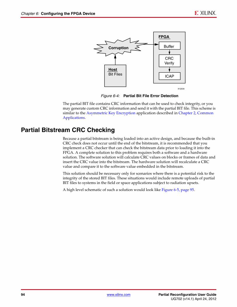
94 www.xilinx.com Partial Reconfiguration User GuideUG702 (v14.1) April 24, 2012
Chapter 6: Configuring the FPGA Device
The partial BIT file contains CRC information that can be used to check integrity, or you may generate custom CRC information and send it with the partial BIT file. This scheme is similar to the Asymmetric Key Encryption application described in Chapter 2, Common Applications.
Partial Bitstream CRC CheckingBecause a partial bitstream is being loaded into an active design, and because the built-in CRC check does not occur until the end of the bitstream, it is recommended that you implement a CRC checker that can check the bitstream data prior to loading it into the FPGA. A complete solution to this problem requires both a software and a hardware solution. The software solution will calculate CRC values on blocks or frames of data and insert the CRC value into the bitstream. The hardware solution will recalculate a CRC value and compare it to the software value embedded in the bitstream.
This solution should be necessary only for scenarios where there is a potential risk to the integrity of the stored BIT files. These situations would include remote uploads of partial BIT files to systems in the field or space applications subject to radiation upsets.
A high level schematic of such a solution would look like Figure 6-5, page 95.
X-Ref Target - Figure 6-4
Figure 6-4: Partial Bit File Error Detection
Buffer
FPGA
CRCVerify
ICAP
Corruption
HostBit Files
X12034
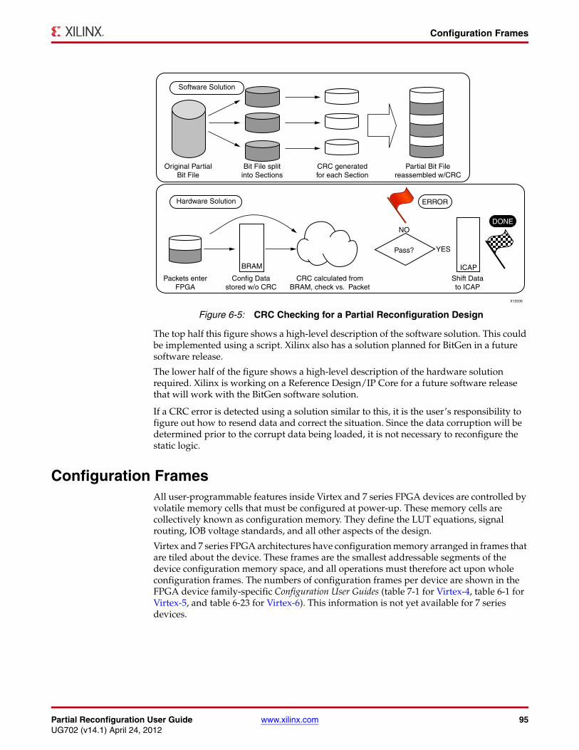
Partial Reconfiguration User Guide www.xilinx.com 95UG702 (v14.1) April 24, 2012
Configuration Frames
The top half this figure shows a high-level description of the software solution. This could be implemented using a script. Xilinx also has a solution planned for BitGen in a future software release.
The lower half of the figure shows a high-level description of the hardware solution required. Xilinx is working on a Reference Design/IP Core for a future software release that will work with the BitGen software solution.
If a CRC error is detected using a solution similar to this, it is the user’s responsibility to figure out how to resend data and correct the situation. Since the data corruption will be determined prior to the corrupt data being loaded, it is not necessary to reconfigure the static logic.
Configuration FramesAll user-programmable features inside Virtex and 7 series FPGA devices are controlled by volatile memory cells that must be configured at power-up. These memory cells are collectively known as configuration memory. They define the LUT equations, signal routing, IOB voltage standards, and all other aspects of the design.
Virtex and 7 series FPGA architectures have configuration memory arranged in frames that are tiled about the device. These frames are the smallest addressable segments of the device configuration memory space, and all operations must therefore act upon whole configuration frames. The numbers of configuration frames per device are shown in the FPGA device family-specific Configuration User Guides (table 7-1 for Virtex-4, table 6-1 for Virtex-5, and table 6-23 for Virtex-6). This information is not yet available for 7 series devices.
X-Ref Target - Figure 6-5
Figure 6-5: CRC Checking for a Partial Reconfiguration Design
Software Solution
Hardware Solution
Original PartialBit File
Bit File splitinto Sections
CRC generatedfor each Section
Partial Bit Filereassembled w/CRC
BRAM ICAP
Pass?
NO
YES
ERROR
DONE
CRC calculated fromBRAM, check vs. Packet
Config Datastored w/o CRC
Packets enterFPGA
Shift Datato ICAP
X12035
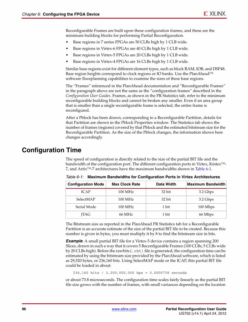
96 www.xilinx.com Partial Reconfiguration User GuideUG702 (v14.1) April 24, 2012
Chapter 6: Configuring the FPGA Device
Reconfigurable Frames are built upon these configuration frames, and these are the minimum building blocks for performing Partial Reconfiguration.
• Base regions in 7 series FPGAs are 50 CLBs high by 1 CLB wide.
• Base regions in Virtex-6 FPGAs are 40 CLBs high by 1 CLB wide.
• Base regions in Virtex-5 FPGAs are 20 CLBs high by 1 CLB wide.
• Base regions in Virtex-4 FPGAs are 16 CLBs high by 1 CLB wide.
Similar base regions exist for different element types, such as block RAM, IOB, and DSP48. Base region heights correspond to clock regions or IO banks. Use the PlanAhead™ software floorplanning capabilities to examine the sizes of these base regions.
The “Frames” referenced in the PlanAhead documentation and “Reconfigurable Frames” in the paragraph above are not the same as the “configuration frames” described in the Configuration User Guides. Frames, as shown in the PR Statistics tab, refer to the minimum reconfigurable building blocks and cannot be broken any smaller. Even if an area group that is smaller than a single reconfigurable frame is selected, the entire frame is reconfigured.
After a Pblock has been drawn, corresponding to a Reconfigurable Partition, details for that Partition are shown in the Pblock Properties window. The Statistics tab shows the number of frames (regions) covered by that Pblock and the estimated bitstream size for the Reconfigurable Partition. As the size of the Pblock changes, the information shown here changes accordingly.
Configuration TimeThe speed of configuration is directly related to the size of the partial BIT file and the bandwidth of the configuration port. The different configuration ports in Virtex, Kintex™-7, and Artix™-7 architectures have the maximum bandwidths shown in Table 6-1.
The Bitstream size as reported in the PlanAhead PR Statistics tab for a Reconfigurable Partition is an accurate estimate of the size of the partial BIT file to be created. Because this number is given in bytes, you must multiply it by 8 to find the bitstream size in bits.
Example: A small partial BIT file for a Virtex-5 device contains a region spanning 200 Slices, drawn in such a way that it covers 5 Reconfigurable Frames (100 CLBs; 5 CLBs wide by 20 CLBs high). Before the rawbits (.rbt) file is generated, the configuration time can be estimated by using the bitstream size provided by the PlanAhead software, which is listed as 29,520 bytes, or 236,160 bits. Using SelectMAP mode or the ICAP, this partial BIT file could be loaded in about:
236,160 bits / 3,200,000,000 bps = 0.0000738 seconds
or about 73.8 microseconds. The configuration time scales fairly linearly as the partial BIT file size grows with the number of frames, with small variances depending on the location
Table 6-1: Maximum Bandwidths for Configuration Ports in Virtex Architectures
Configuration Mode Max Clock Rate Data Width Maximum Bandwidth
ICAP 100 MHz 32 bit 3.2 Gbps
SelectMAP 100 MHz 32 bit 3.2 Gbps
Serial Mode 100 MHz 1 bit 100 Mbps
JTAG 66 MHz 1 bit 66 Mbps
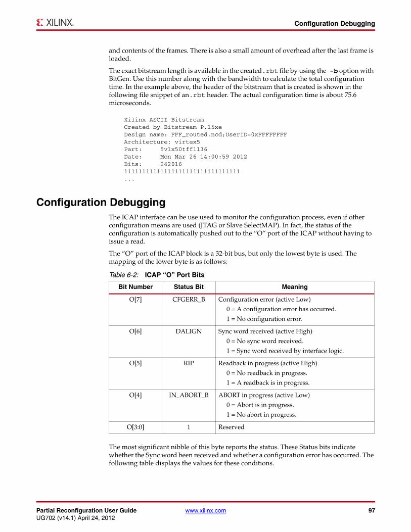
Partial Reconfiguration User Guide www.xilinx.com 97UG702 (v14.1) April 24, 2012
Configuration Debugging
and contents of the frames. There is also a small amount of overhead after the last frame is loaded.
The exact bitstream length is available in the created.rbt file by using the -b option with BitGen. Use this number along with the bandwidth to calculate the total configuration time. In the example above, the header of the bitstream that is created is shown in the following file snippet of an.rbt header. The actual configuration time is about 75.6 microseconds.
Configuration DebuggingThe ICAP interface can be use used to monitor the configuration process, even if other configuration means are used (JTAG or Slave SelectMAP). In fact, the status of the configuration is automatically pushed out to the “O” port of the ICAP without having to issue a read.
The “O” port of the ICAP block is a 32-bit bus, but only the lowest byte is used. The mapping of the lower byte is as follows:
The most significant nibble of this byte reports the status. These Status bits indicate whether the Sync word been received and whether a configuration error has occurred. The following table displays the values for these conditions.
Xilinx ASCII BitstreamCreated by Bitstream P.15xeDesign name: FFF_routed.ncd;UserID=0xFFFFFFFFArchitecture: virtex5Part: 5vlx50tff1136Date: Mon Mar 26 14:00:59 2012Bits: 24201611111111111111111111111111111111...
Table 6-2: ICAP “O” Port Bits
Bit Number Status Bit Meaning
O[7] CFGERR_B Configuration error (active Low)
0 = A configuration error has occurred.
1 = No configuration error.
O[6] DALIGN Sync word received (active High)
0 = No sync word received.
1 = Sync word received by interface logic.
O[5] RIP Readback in progress (active High)
0 = No readback in progress.
1 = A readback is in progress.
O[4] IN_ABORT_B ABORT in progress (active Low)
0 = Abort is in progress.
1 = No abort in progress.
O[3:0] 1 Reserved
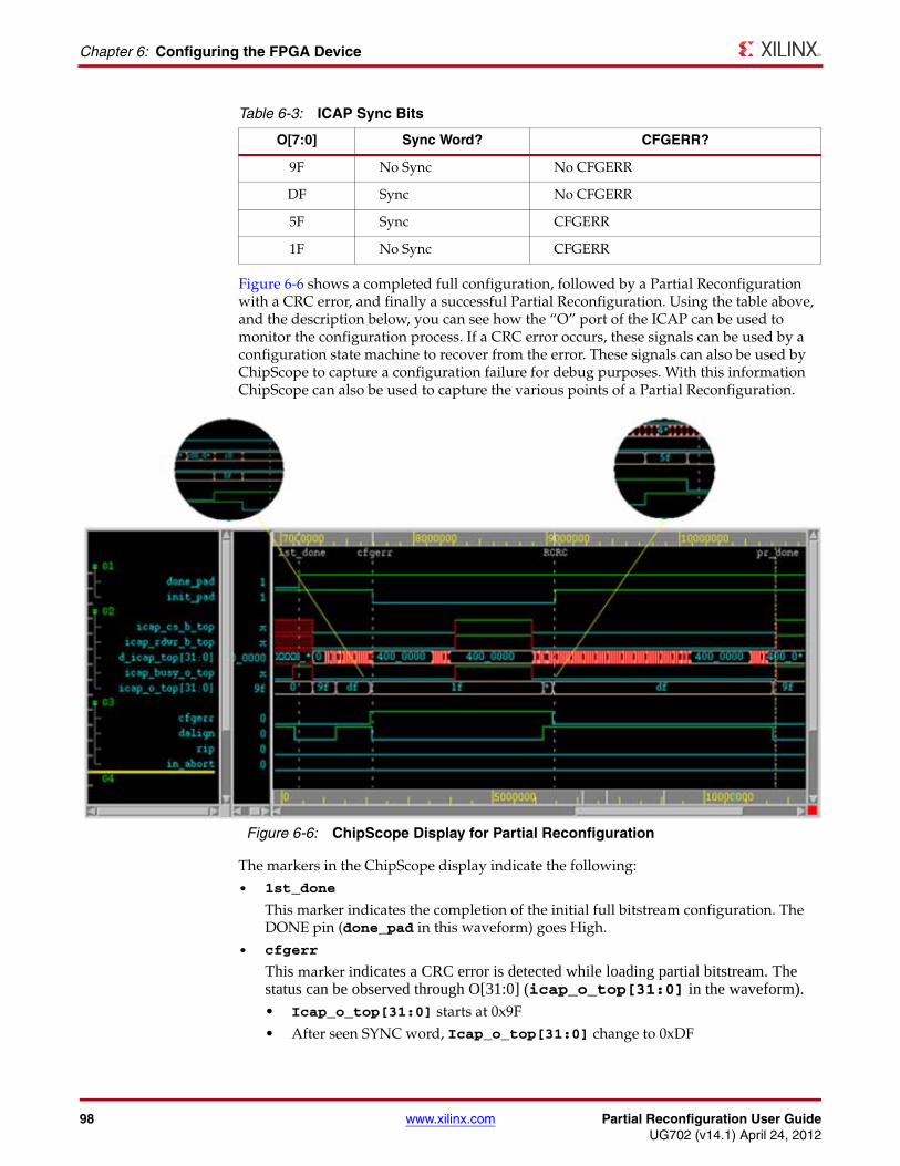
98 www.xilinx.com Partial Reconfiguration User GuideUG702 (v14.1) April 24, 2012
Chapter 6: Configuring the FPGA Device
Figure 6-6 shows a completed full configuration, followed by a Partial Reconfiguration with a CRC error, and finally a successful Partial Reconfiguration. Using the table above, and the description below, you can see how the “O” port of the ICAP can be used to monitor the configuration process. If a CRC error occurs, these signals can be used by a configuration state machine to recover from the error. These signals can also be used by ChipScope to capture a configuration failure for debug purposes. With this information ChipScope can also be used to capture the various points of a Partial Reconfiguration.
The markers in the ChipScope display indicate the following:• 1st_done
This marker indicates the completion of the initial full bitstream configuration. The DONE pin (done_pad in this waveform) goes High.
• cfgerr
This marker indicates a CRC error is detected while loading partial bitstream. The status can be observed through O[31:0] (icap_o_top[31:0] in the waveform).• Icap_o_top[31:0] starts at 0x9F• After seen SYNC word, Icap_o_top[31:0] change to 0xDF
Table 6-3: ICAP Sync Bits
O[7:0] Sync Word? CFGERR?
9F No Sync No CFGERR
DF Sync No CFGERR
5F Sync CFGERR
1F No Sync CFGERR
X-Ref Target - Figure 6-6
Figure 6-6: ChipScope Display for Partial Reconfiguration
Partial Reconfiguration User Guide www.xilinx.com 99UG702 (v14.1) April 24, 2012
Configuration Debugging
• After detect CRC error, Icap_o_top[31:0] change to 0x5F for one cycle, and then switches to 0x1F
• INIT_B pin is pulled low (init_pad in the waveform)
• RCRC
This marker indicates when the partial bitstream is loaded again. The RCRC command resets the cfgerr status, and removes the pull-down on the INIT_B pin (init_pad in this waveform).
• Icap_o_top[31:0] change from 0x1F to 0x5F when the SYNC word is seen
• Icap_o_top[31:0] change from ‘0x5F’ to ‘0xDF’ when RCRC command is received
• pr_done
This marker indicates a successful Partial Reconfiguration.
• Icap_o_top[31:0] change from 0xDF to 0x9F when the DESYNC command is received and no configuration error is detected.
It is important to note that a Partial Reconfiguration does not perform a CRC check until the entire partial BIT file has been loaded, so corrupted data will have already been loaded into the FPGA. If the corruption occurred on an address bit, the static logic could potentially be corrupted, and that status is indicated at the INIT_B configuration register bit. In a system requiring high reliability, it is important to do a CRC check on the partial bitstream prior to sending it to the configuration interface. Information on performing a CRC check on partial bitstreams prior to loading is given in the Partial Bitstream CRC Checking section of this chapter.
If a CRC error occurs, by default the configuration interface will try to issue a full reconfiguration of the device. This is usually not the desired behavior. To prevent this from happening, follow the recommendations given in Generating BIT Files in Chapter 3.

100 www.xilinx.com Partial Reconfiguration User GuideUG702 (v14.1) April 24, 2012
Chapter 6: Configuring the FPGA Device
Partial Reconfiguration User Guide www.xilinx.com 101UG702 (v14.1) April 24, 2012
Chapter 7
Design Considerations
This chapter explains design requirements that are unique to Partial Reconfiguration, and covers specific PR features within the Xilinx® FPGA design software tools.
To take advantage of the Partial Reconfiguration capability of Xilinx FPGA devices, you must analyze the design specification thoroughly, and consider the requirements, characteristics, and limitations associated with PR designs. This simplifies both the design and debug processes, and avoids potential future risks of malfunction in the design.
Design HierarchyGood hierarchical design practices resolve many complexities and difficulties when implementing a Partially Reconfigurable FPGA design. A clear design instance hierarchy simplifies physical and timing constraints. Registering signals at the boundary between static and reconfigurable logic eases timing closure. Grouping logic that is packed together in the same hierarchical level is necessary.
These are all well known design practices that are often not followed in general FPGA designs. Following these design rules is not strictly required in a partially reconfigurable design, but the potential negative effects of not following them are more pronounced. The benefits of Partial Reconfiguration are great, but the extra complexity in design could be more challenging to debug, especially in hardware.
For additional information about design hierarchy, see:
• Repeatable Results with Design Preservation (WP362), and
• Hierarchical Design Methodology Guide (UG748).
102 www.xilinx.com Partial Reconfiguration User GuideUG702 (v14.1) April 24, 2012
Chapter 7: Design Considerations
Design Elements Inside Reconfigurable ModulesNot all logic is permitted to be actively reconfigured. Global logic and clocking resources must be placed in the static region to not only remain operational during reconfiguration, but to benefit from the initialization sequence that occurs at the end of a full device configuration.
Logic that can be placed in an RP includes:
• All logic components that are mapped to a CLB slice in the FPGA. This includes LUTs (look-up tables), FFs (flip-flops), SRLs (shift registers), RAMs, and ROMs.
• Block RAM (BRAM) and FIFO:
• RAMB16, RAMB32_S64_ECC, RAMB18, RAMB36, RAMB18SDP, RAMB36SDP, RAMB18E1, RAMB36E1, BRAM_SDP_MACRO, BRAM_SINGLE_MACRO, BRAM_TDP_MACRO
• FIFO16, FIFO18, FIFO18_36, FIFO36, FIFO36_72, FIFO18E1, FIFO36E1, FIFO_DUALCLOCK_MACRO, FIFO_SYNC_MACRO
Note: The IN_FIFO and OUT_FIFO design elements (7 series only) cannot be placed in an RP. These design elements must remain in static logic.
• DSP blocks: DSP48, DSP48E, DSP48E1
• PCIe (PCI Express) - Entered using PCIe IP
All other logic must remain in static logic, and must not be placed in an RP, including:
• Clocks and Clock Modifying Logic - Includes BUFG, BUFR, MMCM, PLL, DCM, and similar components
• I/O and I/O related components
• MGT (Multi-Gigabit Transceivers) and related components
• Individual architecture feature components (such as BSCAN, STARTUP, etc.)
Dynamic Reconfiguration Using the DRPLogic that must remain in the static region, and therefore is not available for Partial Reconfiguration, can still be reconfigured dynamically through the DRP (Dynamic Reconfiguration Port). The DRP can be used to configure logic blocks such as MMCMs, PLLs, and Multi-Gigabit Transceivers (MGTs).
Information about the DRP and dynamic reconfiguration can be found in these documents:
• Virtex-4 FPGAs Configuration User Guide (UG071)
• Virtex-5 FPGAs Configuration User Guide (UG191)
• Virtex-6 FPGAs Configuration User Guide (UG360)
• 7 Series FPGAs Configuration User Guide (UG470)
Information about using the DRP to configure specific logic blocks can be found in these documents:
• 7 Series FPGAs GTX Transceivers User Guide (UG476)
• Virtex-6 FPGA GTX Transceivers User Guide (UG366)
• MMCM and PLL Dynamic Reconfiguration (7 Series) (XAPP888)
• MMCM Dynamic Reconfiguration (Virtex-6) (XAPP878)
Partial Reconfiguration User Guide www.xilinx.com 103UG702 (v14.1) April 24, 2012
Design Hierarchy
Packing LogicAny logic that must be packed together must be placed in the same group, whether it is static or reconfigurable. For example, I/O registers must remain with the I/O port. Partition boundaries are barriers to optimization. Choose the hierarchical boundaries wisely, since the insertion of proxy logic may result in suboptimal results or routes that are impossible to achieve.
Packing Input/Output Registers in the IOBWhenever possible, it is recommended that input and output registers belong to the same partition as the associated input or output buffer. This will allow the implementation tools to see when a register is connected to I/O logic. When a partition boundary exists between the register and the associated buffer, the tools cannot see across the partition boundary to correctly place the register in the I/O logic.
When this is not possible the implementation tools do have the ability to handle this situation if the following rules are followed:
• The register must have an IOB=FORCE UCF constraint. This will allow the tools to see through the partition boundary and see the register is connected to an I/O buffer, thus allowing the tools to place the register in the I/O logic (ILOGIC/OLOGIC). Using the IOB=FORCE will cause an error in the implementation tools if the register cannot be placed in the I/O logic. This is the desired behavior for situations that require that a register is placed in the I/O logic (for example if a register is clocked by a BUFIO, or when an interface timing requires a fixed delay). In this case using the map -pr b option will not place a register in the I/O logic like it could in a flat flow, or when the buffer and register are in the same partition.
• The IOB=FORCE constraint must be set on the instance name of the register (INST “rp_module/out1_ff” IOB=FORCE;) Do not put this constraint on the register's output or input net.
• The output port of the RP must have the PARTITION_PIN_DIRECT_ROUTE constraint to prevent the tools from inserting proxy logic between the buffer and the register (which would prevent the register from being packed in the I/O logic). Also, this forces all RMs variants associated with this RP to have the same IOB=FORCE constraint, and disables the ability to generate a black box RM for this RP.
Design Instance HierarchyThe simplest method is to instantiate the Reconfigurable Partitions in the top-level module. Each Reconfigurable Partition must correspond to exactly one instance. The instance has multiple modules with which it is associated.
Submodules in Reconfigurable ModulesAll the logic for a Reconfigurable Module must exist in the same directory. If an RM requires submodule netlist files, the PlanAhead™ software loads them only if they exist in the same local folder as the root RM netlist. PlanAhead needs the full contents of each Reconfigurable Module to both constrain and implement each Configuration.
If other netlists (IP core netlists, for example) must be merged in from other directories, the ngcbuild utility can be used to pre-assemble an RM into a single netlist that is easily referenced in a Partial Reconfiguration project. NGCBuild takes EDIF and/or NGC sources, along with the full set of options that are valid for ngdbuild (including -sd and -uc), and produces a single, constraint-annotated NGC file.
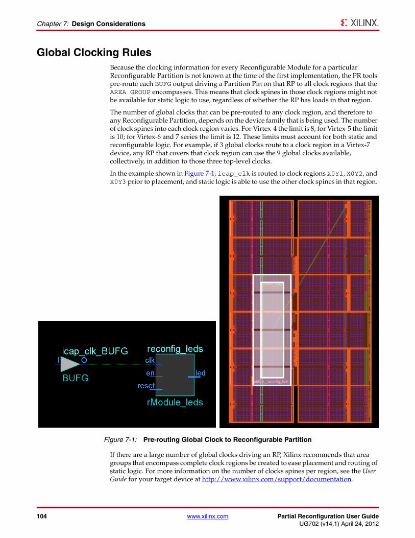
104 www.xilinx.com Partial Reconfiguration User GuideUG702 (v14.1) April 24, 2012
Chapter 7: Design Considerations
Global Clocking RulesBecause the clocking information for every Reconfigurable Module for a particular Reconfigurable Partition is not known at the time of the first implementation, the PR tools pre-route each BUFG output driving a Partition Pin on that RP to all clock regions that the AREA GROUP encompasses. This means that clock spines in those clock regions might not be available for static logic to use, regardless of whether the RP has loads in that region.
The number of global clocks that can be pre-routed to any clock region, and therefore to any Reconfigurable Partition, depends on the device family that is being used. The number of clock spines into each clock region varies. For Virtex-4 the limit is 8; for Virtex-5 the limit is 10; for Virtex-6 and 7 series the limit is 12. These limits must account for both static and reconfigurable logic. For example, if 3 global clocks route to a clock region in a Virtex-7 device, any RP that covers that clock region can use the 9 global clocks available, collectively, in addition to those three top-level clocks.
In the example shown in Figure 7-1, icap_clk is routed to clock regions X0Y1, X0Y2, and X0Y3 prior to placement, and static logic is able to use the other clock spines in that region.
If there are a large number of global clocks driving an RP, Xilinx recommends that area groups that encompass complete clock regions be created to ease placement and routing of static logic. For more information on the number of clocks spines per region, see the User Guide for your target device at http://www.xilinx.com/support/documentation.
X-Ref Target - Figure 7-1
Figure 7-1: Pre-routing Global Clock to Reconfigurable Partition
Partial Reconfiguration User Guide www.xilinx.com 105UG702 (v14.1) April 24, 2012
Active Low Resets and Clock Enables
Active Low Resets and Clock EnablesIn current Xilinx FPGA architectures there are no local inverters on control signals (resets or clock enables).
The following description uses a reset as the example, but the same applies for clock enables.
If a design uses an active low reset a LUT must be used to invert the signal. In non-partition designs that use all active low resets multiple LUTs will be inferred, but can be combined into a single LUT and pushed into the I/O elements (LUT goes away). In non-partition designs that use a mix of high and low, the LUT inverters can be combined into one LUT that remains in the design, but that has minimal effect on routing and the timing of the reset net (output of LUT can still be put on global resources). However, for a design that uses active low resets on a partition, it is possible to get inverters inferred inside of the partition that cannot be pulled out and combined. This makes it impossible to put the reset on global resources, and can lead to poor reset timing and to routing issues if the design is already congested.
The best way to avoid this is to avoid using active low control signals. However, there are cases where this is not possible (for example, when using an IP core with an Advanced eXtensible Interface (AXI) interface). In these cases the design should assign the Active- low reset to a signal at the top level, and use that new signal everywhere in the design.
As an example:
reset_n <= !reset;
Use reset_n signal for all cases, and do not use the !reset assignments on signals or ports.
This will ensure that a LUT will be inferred only for the reset net for the whole design, and will have a minimal effect on design performance.
Decoupling FunctionalityBecause the reconfigurable logic is modified while the FPGA device is operating, the static logic connected to outputs of Reconfigurable Modules must ignore data from Reconfigurable Modules during Partial Reconfiguration. The Reconfigurable Modules will not output valid data until Partial Reconfiguration is complete and the reconfigured logic is reset. A common design practice to mitigate this issue is to register all output signals (on the static side of the interface) from the Reconfigurable Module. An enable signal can be used to isolate the logic until it is completely reconfigured.
The static portion should include the logic required for the data and interface management. It can implement mechanisms such as handshaking or disabling interfaces (which might be required for bus structures to avoid invalid transactions). It is also useful to consider the down-time performance effect of a PR module (that is, the unavailability of any shared resources included in a PR module during or after reconfiguration).
You must assert local reset in the reconfigured logic after reconfiguration has completed to ensure a known good starting state. Unlike a full device configuration, there are no dedicated functions such as GSR (global set-reset) or GTS (global tri-state) to force logic to an initial state. Because the logic surrounding a reconfiguring frame is operating during the reconfiguration, it is impossible to predict the state or activity of the new logic when it is released for use. This is true for I/O logic as well as general fabric logic.
106 www.xilinx.com Partial Reconfiguration User GuideUG702 (v14.1) April 24, 2012
Chapter 7: Design Considerations
Design Revision ChecksA partial bitstream contains programming information and little else, as described in Chapter 6, Configuring the FPGA Device. While you do not need to identify the target location of the bitstream (the die location is determined by the addressing that is part of the BIT file), there are no checks in the hardware to ensure the partial bitstream is compatible with the currently operating design. Loading a partial bitstream into a static design that was not implemented with that reconfigurable module variant revision can lead to unpredictable behavior.
Xilinx suggests that you prefix a partial bitstream with a unique identifier indicating the particular design, revision and module variant that follows. This identifier can be interpreted by your configuration controller to validate that the partial bitstream is compatible with the resident design - a mismatch can be detected and the incompatible bitstream can be rejected before being loaded into configuration memory. This functionality must be part of your design, and would be similar to or in conjunction with decryption and/or CRC checks, as described in PRC/EPRC: Data Integrity and Security Controller for Partial Reconfiguration (XAPP887).
A BitGen feature provides a simple mechanism for tagging a design revision. The -g USR_ACCESS switch allows you to enter a revision ID directly into the bitstream. This ID is placed in the USR_ACCESS register, accessible from the FPGA fabric through a library primitive of the same name. Partial Reconfiguration designs can read this value and compare it to information in a partial bitstream to confirm the revisions of the design match. More information on this switch can be found in the “BitGen” chapter in the Command Line Tools User Guide, (UG628) and in Bitstream Identification with USR_ACCESS (XAPP497).
Defining Reconfigurable Partition BoundariesPartial reconfiguration is done on a frame-by-frame basis. As such, when partial BIT files are created, they are built with a discrete number of configuration frames. When the physical region for a Partition is defined, the PlanAhead software reports the number of reconfigurable regions that are consumed, as well as an estimate for the corresponding bitstream size. The estimates from PlanAhead are accurate within 2-3%.
Partition boundaries do not have to align to reconfigurable frame boundaries, but the most efficient place and route results are achieved when this is done. Static logic is permitted to exist in a frame that will be reconfigured, as long as:
• It is outside the area group defined by the Pblock (unless forced inside with a LOC constraint), and
• It does not contain dynamic elements such as bock RAM, Distributed (LUT) RAM, or SRLs.
When static logic is placed in a reconfigured frame, the exact functionality of the static logic is rewritten, and is guaranteed not to glitch.
Irregular shaped Partitions (such as a T or L shapes) are permitted but discouraged. Placement and routing in such regions can become challenging, because routing resources must be entirely contained within these regions. Boundaries of Partitions can touch, but this is not recommended, as some separation helps mitigate potential routing restriction issues. Nested or overlapping Reconfigurable Partitions (Partitions within Partitions) are not permitted. Design rule checks (Tools > Report DRC) validate the Partitions and settings in a PR project.
Partial Reconfiguration User Guide www.xilinx.com 107UG702 (v14.1) April 24, 2012
Proxy Logic
The partial BIT files that are created are based upon the AREA_GROUP RANGE constraints set by the user. To generate the smallest BIT files possible, and to avoid complications or errors, only define AREA_GROUP RANGE constraints for the elements that exist in the full set of Reconfigurable Modules for a Reconfigurable Partition. If you are using PlanAhead, this means unchecking any unnecessary element type in the General tab of the Pblock Properties pane (see Figure 4-17, page 65).
Finally, only one Reconfigurable Partition can exist per physical Reconfigurable Frame.
A Reconfigurable Frame is the smallest size physical region that can be reconfigured, and aligns with clock region or IO bank boundaries. A Reconfigurable Frame cannot contain logic from more than one Reconfigurable Partition. If it were to contain logic from more than one Reconfigurable Partition, it would be very easy to reconfigure the region with information from an incorrect Reconfigurable Module, thus creating contention. The software tools are designed to avoid that potentially dangerous occurrence.
Proxy LogicPartition Pins are defined as the interface between static and reconfigurable logic. No special logic or tags are required to accommodate this definition. The software handles these points automatically. In most cases, a LUT1 is inserted at this interface point to represent this node. Since this LUT exists in the hierarchical level of the static logic, it exists in the same logical and physical location for every Configuration. Since the physical location itself is within the Reconfigurable Partition to which it connects, reconfiguration accommodates connecting logic internal to the RM to this known interface point.
As noted in Constraints in Chapter 3, proxy logic can be constrained in the UCF. The pr2ucf utility generates constraints for all the proxy logic from a Configuration that has been implemented. Providing location constraints for proxy logic is not required. This section also includes information for setting timing constraints to and from individual and grouped Partition Pins.
Controlled RoutesIn general all pins of a reconfigurable partition have associated proxy logic, except for global nets (nets driven by a global buffer). However, if appropriate the PARTITION_PIN_DIRECT_ROUTE constraint can be used to prevent the insertion of proxy logic on individual partition pins. The use of the constraint has the following requirements:
• The driver and loads of the net must exist in every configuration of the design.
• Black box modules are not supported with this constraint.
• The route must use identical routing resources in every configuration. For general routing resources this requires the use of Directed Routing constraints. For information on Directed Routing constraints refer to the Constraints Guide (UG625).
The syntax for the PARTITION_PIN_DIRECT_ROUTE constraint is as follows:
PIN "<Partition_Name>.<PinName>" PARTITION_PIN_DIRECT_ROUTE = TRUE;
108 www.xilinx.com Partial Reconfiguration User GuideUG702 (v14.1) April 24, 2012
Chapter 7: Design Considerations
Black BoxesThe Partial Reconfiguration software allows black boxes to be implemented as Reconfigurable Modules. This is an effective way to reduce the size of full configuration BIT file, and therefore reduce the initial configuration time. To create a black box Partition, create a Reconfigurable Module with no associated netlist file. The source shown in PlanAhead is listed as Blackbox module.
Even though a black box has no user logic contained in the logical representation of the design, the physical region is not entirely empty. As noted in the Proxy Logic section above, a LUT1 is inserted for each Partition Pin as the interface to the Reconfigurable Partition. Because these proxy LUTs must exist within the reconfigurable region, they appear in the black box, along with their connections outside the region.
The BitGen compression (-g compress) feature may be enabled to reduce the size of BIT files. This option looks for repeated configuration frame structures to reduce the amount of configuration data that must be stored in the BIT file. This savings is seen in reduced configuration and reconfiguration time. When the compression option is applied to a routed PR design, all of the BIT files (full and partial) are created as compressed BIT files. This option is especially useful when coupled with the technique of building a PR design with black box RMs.
Module-Level Constraint FilesIn order to adequately constrain the entire design, you must supply constraints for both the static and reconfigurable portions of the design. This can be done in a number of ways. The static logic is controlled by any constraints in the top-level netlists and the main UCFs supplied to the PlanAhead software or the Tcl scripts. Constraints, such as I/O location constraints, to be shared across all variants of the Reconfigurable Partitions must be included in the top-level UCFs.
If constraints apply only to specific Reconfigurable Modules, they may be supplied in one of three different methods:
• As part of the netlist itself
Because synthesis tools can embed constraints within the design netlist, these constraints are read in with the rest of the contents of that file.
• In a UCF placed alongside the RM netlist
When a netlist is loaded into PlanAhead as a Reconfigurable Module, a UCF can be supplied at the same time (see Figure 7-2). The constraints in this UCF must be scoped to the module level – references to instances within the RM must not have the full hierarchical path to the instance.
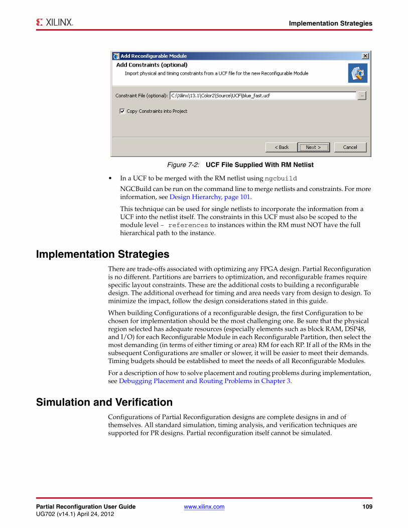
Partial Reconfiguration User Guide www.xilinx.com 109UG702 (v14.1) April 24, 2012
Implementation Strategies
• In a UCF to be merged with the RM netlist using ngcbuild
NGCBuild can be run on the command line to merge netlists and constraints. For more information, see Design Hierarchy, page 101.
This technique can be used for single netlists to incorporate the information from a UCF into the netlist itself. The constraints in this UCF must also be scoped to the module level – references to instances within the RM must NOT have the full hierarchical path to the instance.
Implementation StrategiesThere are trade-offs associated with optimizing any FPGA design. Partial Reconfiguration is no different. Partitions are barriers to optimization, and reconfigurable frames require specific layout constraints. These are the additional costs to building a reconfigurable design. The additional overhead for timing and area needs vary from design to design. To minimize the impact, follow the design considerations stated in this guide.
When building Configurations of a reconfigurable design, the first Configuration to be chosen for implementation should be the most challenging one. Be sure that the physical region selected has adequate resources (especially elements such as block RAM, DSP48, and I/O) for each Reconfigurable Module in each Reconfigurable Partition, then select the most demanding (in terms of either timing or area) RM for each RP. If all of the RMs in the subsequent Configurations are smaller or slower, it will be easier to meet their demands. Timing budgets should be established to meet the needs of all Reconfigurable Modules.
For a description of how to solve placement and routing problems during implementation, see Debugging Placement and Routing Problems in Chapter 3.
Simulation and VerificationConfigurations of Partial Reconfiguration designs are complete designs in and of themselves. All standard simulation, timing analysis, and verification techniques are supported for PR designs. Partial reconfiguration itself cannot be simulated.
X-Ref Target - Figure 7-2
Figure 7-2: UCF File Supplied With RM Netlist
110 www.xilinx.com Partial Reconfiguration User GuideUG702 (v14.1) April 24, 2012
Chapter 7: Design Considerations
Using High Speed TransceiversXilinx high speed transceivers (GT11, GTP, GTX) have dedicated connections to many of their pins. These dedicated connections require that the I/O connected to these pins be handled differently than general purpose I/O. For the tools to recognize the direct connection, the transceivers and all associated I/O logic must be contained within the same Partition. This includes all the pads and buffers as well as all transceiver logic.
Interaction with Other Xilinx ToolsThis section discusses Interaction with Other Xilinx Tools, and includes:
• Interaction with ChipScope Pro
• Interaction with System Generator for DSP and CORE Generator
Interaction with ChipScope ProChipScope™ Pro analyzer inserts logic analyzer, bus analyzer, and virtual I/O low-profile software cores directly into a design, allowing you to view any internal signal or node, including embedded hard or soft processors. Instrumentation of designs can be done by means of two methods, the:
• Xilinx CORE Generator™ software, or
• ChipScope Pro Core Inserter.
Both methods can be used in conjunction with Partial Reconfiguration, but limitations do exist.
When using the Xilinx CORE Generator software, you create netlist-based cores to be instantiated in the design. As long as the boundaries of the Reconfigurable Partitions are not modified, these cores can be instantiated easily to debug the portion of the design in question. This is easy to manage when all the ChipScope Pro cores are placed within the static portion of the design. The ICON core must remain in the static logic due to the fact that it contains both BUFG and BSCAN elements.
If ILA or VLO cores are instantiated in a Reconfigurable Partition, additional measures must be taken. The bounding region in the floorplan must include all the necessary elements to implement the ChipScope Pro cores, specifically enough block RAM to build the requested functionality. Given the size and physical location of this requirement, this could have a significant impact on the Reconfigurable Partition.
The CONTROL bus that connects the ICON core and the ILA or VIO cores is defined as bidirectional, to simplify HDL instantiation. In truth, this bus is actually a collection of 35 signals going from ICON to ILA, and one signal going the opposite direction. Bidirectional signals are not permitted on Reconfigurable Partition interfaces due to proxy logic insertion, so a wrapper for each ChipScope Pro core must be created to convert these inout ports to input and output ports.
For a complete description of how ChipScope Pro cores are inserted into Reconfigurable Modules, including samples of the HDL wrappers for ICON, ILA, and VIO cores, see Answer Record 42899.
If there is a need to debug signals in multiple regions (static and reconfigurable), this can be done, but the appropriate signals (data, trigger, and/or control bus) must be threaded up from the individual Reconfigurable Partitions to the top-level. This requires
Partial Reconfiguration User Guide www.xilinx.com 111UG702 (v14.1) April 24, 2012
Interaction with Other Xilinx Tools
modifications to the Partition interface and must be done for each Reconfigurable Module. This strategy is supported for the CORE Generator flow only.
The ChipScope Pro Core Inserter software modifies the design at the netlist itself, rather than the HDL source. This flow is supported in PlanAhead, but probe points are limited to signals that exist in the static logic. If an attempt to probe logic in a Reconfigurable Module is made, the tool reports that this modification changes the Partition interface, and is therefore not allowed.
Interaction with System Generator for DSP and CORE GeneratorWhen using advanced tools and IP from Xilinx or third party sources, rules similar to those for ChipScope Pro software must be followed. Because these tools build and modify designs at the HDL or netlist level, they work smoothly with a bottom-up synthesis approach required by the Partial Reconfiguration flow. Considerations must be made for the definition of the reconfigurable regions (to ensure the proper elements are contained within) and for timing in and out of the Reconfigurable Partition, but other than these general requirements, these tools will work well with Partial Reconfiguration.
One significant consideration for use of Partial Reconfiguration with advanced tools and IP is the contents of these design blocks. No global clocks or clock modifying logic (BUFG, DCM, PLL, etc.) may exist in any module to be reconfigured.
Like the ChipScope ICON core, certain blocks will be required to remain in static logic if they contain non-reconfigurable design elements.
Interaction with EDKTo understand the Partial Reconfiguration flow for a processor design developed in EDK, see the Partial Reconfiguration of a Processor Peripheral Tutorial (UG744). This tutorial can be downloaded from the Partial Reconfiguration web page at:
http://www.xilinx.com/tools/partial-reconfiguration
Details of the Partial Reconfiguration interaction with EDK:
• When you create a PlanAhead project and specify the top-level netlist for a design developed in EDK, specify the top-level netlist in the synthesis directory (../synthesis/top_level_filename.ngc)instead of the netlist in the implementation directory (../implementation/top_level_filename.ngc).
Any netlists that you intend to use as reconfigurable modules should be removed from the EDK implementation directory prior to launching PlanAhead. Since the removed netlists are called out in the top-level netlist in the EDK synthesis directory, PlanAhead will offer you the choice of treating these netlists as black boxes. After allowing PlanAhead to create the black boxes, you can create netlists with the same port definitions as the removed netlists outside of EDK and add these netlists as new reconfigurable modules with PlanAhead.
• When generating BIT files for a design that is an EDK processor system, you must run the Data2MEM program on the BIT file to update block RAM contents with the compiled software program. When running in the PlanAhead environment, there are no direct links to call the Data2MEM program. However, you can have BitGen call Data2MEM directly using the BitGen -bd switch. In PlanAhead, when you choose the Generate Bitstream command, a dialog box with available BitGen options opens. In the list of options there will be a -bd switch. In the value field for the -bd switch, you can browse to the ELF file generated by EDK.
112 www.xilinx.com Partial Reconfiguration User GuideUG702 (v14.1) April 24, 2012
Chapter 7: Design Considerations
You can also use this switch from the BitGen command line, instead of running Data2MEM separately. An example command is shown below:
bitgen -bd <path_to_ELF_file>/executable.elf
Partial Reconfiguration Design ChecklistConsider the following items for a design using Partial Reconfiguration:
• Are you using Global Clock Buffers, Regional Clock Buffers, or Clock Modifying Blocks (DCM, MMCM, PLL)?
• Global Clock Buffers, Regional Clock Buffers, and Clock Modifying Blocks must be in static logic.
- See the Design Elements Inside Reconfigurable Modules section of this chapter for more information.
- See the Global Clocking Rules section of this chapter for complete details on global clock implementation.
• Are you using device features blocks (BSCAN, CAPTURE, DCIRESET, FRAME_ECC, ICAP, KEY_CLEAR, STARTUP, USR_ACCESS)?
• Device feature blocks are recommended to be in static logic.
- See the Design Elements Inside Reconfigurable Modules section of this chapter for more information.
• Is all logic that must be packed together in the same Reconfigurable Partition?
• Any logic that must be packed together must be in the same RP/RM.
- See the Packing Logic section of this chapter for more information.
• Are critical paths contained within the same partition?
• Reconfigurable partition boundaries limits some optimization and packing, so critical paths should be contained within the same partition.
- See the Packing Logic section of this chapter for more information.
• Do you have I/Os in reconfigurable modules?
• All I/Os must reside in static logic.
• Have you created decoupling logic on the outputs of your RMs?
• During reconfiguration the outputs of RPs are in a indeterminate state, so decoupling logic must be used to prevent data corruption.
- See the Decoupling Functionality section of this chapter for more information.
• Are you resetting the logic in an RM after reconfiguration?
• After reconfiguration, new logic may have moved on from its initial value. A local reset must be used to ensure it comes up as expected when decoupling is released.
- See the Decoupling Functionality section of this chapter for more information.
• Do you have high speed transceivers in your design?
• High speed transceivers must remain in the static Partition.
- See the Using High Speed Transceivers section of this chapter for specific requirements.
Partial Reconfiguration User Guide www.xilinx.com 113UG702 (v14.1) April 24, 2012
Partial Reconfiguration Design Checklist
• Are you using ChipScope Pro Analyzer with your Partial Reconfiguration design?
• ChipScope Pro can be used with Partial Reconfiguration, but certain requirements must be met.
- See the Interaction with ChipScope Pro section of this chapter for more information.
• Are you using System Generator for DSP or CORE Generator with your Partial Reconfiguration design?
• Both System Generator and CORE Generator can be used with Partial Reconfiguration, but certain requirements must be met.
- See the Interaction with System Generator for DSP and CORE Generator section of this chapter for more information.
• Are you using EDK with your Partial Reconfiguration design?
• EDK can be used with Partial Reconfiguration, if certain requirements are met.
- See the Interaction with EDK section of this chapter for more information.
- See the Partial Reconfiguration of a Processor Peripheral Tutorial (UG744) for more information. This tutorial can be downloaded from the Partial Reconfiguration web page at: http://www.xilinx.com/tools/partial-reconfiguration.htm
• Do you need to have encrypted partial BIT files with a Virtex-4 or Virtex-5 design?
• This is not directly supported for Virtex-4 or Virtex-5.
- See Known Limitations in Appendix A for more information.
- See Xilinx Application Note, PRC/EPRC: Data Integrity and Security Controller for Partial Reconfiguration (XAPP887) for information on building encrypted partial BIT files for Virtex-5.
• Do you need to update block RAM contents?
• Data2MEM is not supported for partial bitstreams.
- See Known Limitations in Appendix A for more information.
• Do all of your RPs have Area Groups following Xilinx Guidelines?
• There are several requirements for Area Group ranges for RPs.
- See Area Group Constraints in Chapter 3 for more information.
• Have you created your Reconfigurable Partition Area Groups in an efficient manner?
• Partial Reconfiguration is done on a frame by frame basis, so Xilinx has recommendations for how to create them.
- See the Defining Reconfigurable Partition Boundaries section of this chapter for more information.
• Have you validated consistency between all configurations?
• pr_ verify is used to ensure that all configurations have matching imported resources.
- See pr_verify in Chapter 3 for more information.
• Are you aware of the particular configuration requirements for your device?
• Each family has specific configuration considerations.
- See Chapter 6, Configuring the FPGA Device.
- See the Configuration User Guide for your device family. Configuration User Guides are listed in Appendix C, Additional Resources.

114 www.xilinx.com Partial Reconfiguration User GuideUG702 (v14.1) April 24, 2012
Chapter 7: Design Considerations
Partial Reconfiguration User Guide www.xilinx.com 115UG702 (v14.1) April 24, 2012
Appendix A
Known Issues and Known Limitations
This appendix lists the known issues and limitations for the 14.1 Partial Reconfiguration software.
Known IssuesFor a complete listing of Partial Reconfiguration Known Issues, see Answer Record 35019.
Known Issues are:
• Typos in Tcl scripts might be silently ignored.
When using the sample Tcl scripts supplied with the Color2 design, names of instances (such as Configurations, Reconfigurable Modules, and paths) must be modified to accommodate user designs. If a name is misspelled or otherwise incorrect, no error messaging is returned to communicate that mistake back to the user. Closely examine the report files to ensure all the correct files and settings have been applied during the synthesis and implementation runs.
Known LimitationsFollowing are known limitations:
• No Spartan® device families are supported by Partial Reconfiguration software.
• Bitstream generation for Artix™-7 devices is currently disabled, pending hardware verification.
• Partial Reconfiguration cannot be implemented in ISE software for Virtex®-7 FPGAs that use stacked silicon interconnect (SSI) technology.
• ISE® Design Suite 14.1 restricts the component types that are permitted in reconfigurable regions. Multi-gigabit transceivers (MGTs), configuration components (STARTUP, BSCAN, ICAP, etc.) and IO and related components (ILOGIC/OLOGIC, IODELAY, SERDES, etc., plus BUFR) must remain in the static part of the design. Recent testing has uncovered rare scenarios where specific components do not function perfectly after reconfiguration, so it was decided for the safety of all partial reconfiguration designs to remove these resource types from consideration. Unfortunately this requires limiting all component types that reside in these reconfiguration frames. Xilinx® is currently investigating methods to ensure design safety while re-enabling these components in a future software release.
• In PlanAhead, submodule Area Groups within an RP are not permitted.
• Encrypted partial BIT files (by means of bitgen -g encrypt) are not directly supported for Virtex-4 and Virtex-5 devices. Xilinx Application Note:
116 www.xilinx.com Partial Reconfiguration User GuideUG702 (v14.1) April 24, 2012
Appendix A: Known Issues and Known Limitations
PRC/EPRC: Data Integrity and Security Controller for Partial Reconfiguration (XAPP887) shows how to build encrypted partial BIT files for Virtex-5 devices.
Encrypted partial BIT files are supported for 7 series and Virtex-6 devices. Users must supply the same NKY file for each configuration to ensure consistency of the encryption key values.
The ICAP must be used, with an 8-bit bus only, for Partial Reconfiguration for encrypted Virtex-6 partial BIT files. Reconfiguration through external configuration ports is not permitted when encryption is used.
• If a Reconfigurable Partition (RP) contains BRAM or FIFO blocks, these special considerations apply:
• If RAMB18 are used, the entire RAMB36 block must be included in the AREA_GROUP range. You cannot break a RAMB36 into two RAMB18 with one belonging to the RP and one belonging to static logic. The entire RAMB36 must belong to the same partition.
• If using cascade mode, the smallest unit should be a RAMB36 because there are shared signals between the two RAMB18.
• When on BRAM/FIFO is used, all BRAM/FIFO within the clock region are reconfigured. For this reason BRAM/FIFO that belong to static logic cannot be placed in the same configuration frame as BRAM/FIFO that belong to the RP. It is recommended that all RPs are aligned to clock region boundaries or configuration frame boundaries, and this is especially true for RPs that contain BRAM/FIFO blocks.
• In PlanAhead, the Data2MEM program cannot be run directly to update block RAM contents (for example, in an EDK processor system). You can, however, run Data2MEM as part of bitstream generation by specifying that the BitGen command will run with the -bd switch. For details, see Interaction with EDK in Chapter 7.
• Bi-directional Partition Pins are not supported; the interface between static and reconfigurable logic must use unidirectional pins only.
Partial Reconfiguration User Guide www.xilinx.com 117UG702 (v14.1) April 24, 2012
Appendix B
Partial Reconfiguration Migration Guide
This Partial Reconfiguration (PR) Migration Guide provides step-by-step instructions to migrate designs created with the 9.2.04i Modular Design Early Access PR (EA) solution to the Partition-based ISE® 14 solution described in this user guide.
The basic ISE 14 Partial Reconfiguration design flow is the same as the ISE 13 design flow, and the method of migration is also the same whether the destination is ISE 13 or ISE 14.
Differences Between the Early Access and Production Solutions
Compatible Designs for MigrationAny EA design that targets Virtex®-4 or newer can be migrated to the ISE 14 solution. Users will need to create a new PlanAhead™ software project in ISE 14. To create this project, simply follow the instructions found in Chapter 4, PlanAhead Support.
Bus Macro instantiations no longer requiredBus Macros (BMs) are no longer needed. Partition Pins are automatically managed, and this automation replaces some of the aspects of Bus Macro functionality. Both Synchronous and Asynchronous Bus Macros were available in the EA solution. To follow good hierarchical design practices in registering boundaries and to decouple the reconfigurable logic, you can add registers in HDL to replace the functionality of the output registers delivered within Synchronous Bus Macros.
It is very important to register the partition boundaries, and to use enables with these registers. During reconfiguration, the activity in these regions is indeterminate and could lead to design corruption if the output of the reconfiguring logic is used. Therefore, you should register boundaries with enables to disable the reconfigurable region during reconfiguration.
PR-Specific Environment Variables DeprecatedThe EA solution required several different environment variables to be set. These are no longer required for the ISE 14 solution. Please make sure to unset all environment variables that were set specifically for the EA solution.
118 www.xilinx.com Partial Reconfiguration User GuideUG702 (v14.1) April 24, 2012
Appendix B: Partial Reconfiguration Migration Guide
MODE Constraint DeprecatedWith the EA solution, the tools had to be explicitly told which area groups were reconfigurable. This was handled by specific constraints added to the UCF (MODE=RECONFIG). These constraints are no longer required. This functionality has been replaced by using the ‘Set Reconfigurable’ option in PlanAhead which in turn adds the ‘Reconfigurable=TRUE’ information to the xpartition.pxml.
'NGDBuild -modular' Switch DeprecatedIt is no longer necessary to specifically tell NGDBuild that you are running a PR design. This concept is now handled by an xpartition.pxml file. See the following section for more details.
Partition Information is Stored in the xpartition.pxml FileIn the ISE 14 solution, a PXML file manages partition-specific information. This file is named xpartition.pxml, and this name cannot be changed. This file is ASCII XML and is created for each implementation. Most of the PR-specific information (everything save for Area Group Range constraints) is contained in the xpartition.pxml file. The tools will automatically check for the xpartition.pxml file. Any design with reconfigurable partitions requires that the xpartition.pxml file be present and have at least one partition defined. If it is not found, the design is treated as a ‘flat’ design.
The xpartition.pxml file is generated by PlanAhead, and should not be edited. If you are using the Xilinx® HD Tcl scripting method to implement the design, the file will be created when the implementation script is run.
Tcl Flow is the Only Command Line OptionIn the EA solution, the tools could be run directly from command line. While the tools can also be run in ISE 14 from command line, the difference is that the PXML file needs to exist before the ISE 14 tools will treat the design as a PR design. This requires the user to script the flow in Tcl to generate the PXML file.
Note: To help get started with the Xilinx HD Tcl scripting method, some basic ‘flat flow’ scripts can be generated using the ‘Generate Scripts Only’ option when creating runs. To write Xilinx HD Tcl scripts that leverage the Reconfigurable Partition promoting, implementing, and importing functionality, see Chapter 5, Command Line Scripting.
UCF Only Required in NGDBuildThere was also a requirement that the UCF be available for post-Translate implementation processes (MAP and PAR) in the EA solution. This is no longer the case, and all information that is required for downstream implementation processes is embedded in the design database files.
Manage Full-Design Timing ConstraintsAs ISE 14 implements complete designs in context, timing constraints and timing budgets should be established. Review the recommendations for timing management in Chapter 3, Software Tools Flow.
Partial Reconfiguration User Guide www.xilinx.com 119UG702 (v14.1) April 24, 2012
Migrating a Design
BUFRs Require Partition Pins in Virtex-5In the EA solution, BUFRs had several restrictions, but the network did not require Bus Macros. In the ISE 14 solution, Partition Pins are added to the BUFR networks to meet clock region pre-routing requirements. This is only true for Virtex-5.
Migrating a DesignEA designs can easily be migrated to the ISE 14 solution. The first step is to remove or replace the Bus Macros in the HDL and regenerate (resynthesize) the appropriate netlists. Once the netlists are correctly set up, a new PlanAhead project must be created in the ISE 14 solution. Do not attempt to directly migrate a 9.2.04i PlanAhead project to 14.1 PlanAhead.
Bus Macro RemovalThe first step in design migration is removal of the Bus Macros, and this is done in HDL. There are two general ways to remove BMs:
• Remove Bus Macro Instantiations
• PRO: Leaves cleaner HDL
• CON: This is time consuming and must be done for all instances
• Redefine Bus Macros
• PRO: This is the fastest way to replace large numbers of BMs
• CON: This leaves BM instantiations littered throughout a design
If you fail to make any attempt to remove the BMs and remove the BM NMC files, then you will receive the following error in Translate (NGDBuild):
ERROR:NgdBuild:604 - logical block 'my_RP/my_BM_GENERATE[7].my_BM' with type 'busmacro_xc5v_async_enable' could not be resolved. A pin name misspelling can cause this, a missing edif or ngc file, case mismatch between the block name and the edif or ngc file name, or the misspelling of a type name. Symbol 'busmacro_xc5v_async_enable' is not supported in target 'virtex5'.
VHDL Bus Macro Removal
Remove Only Bus Macros Instantiations
In the following example, an asynchronous BM is used. To simplify the BM removal process in this example, the BM inputs are connected directly to the BM outputs. However, this is not necessary and a single network could replace the BM inputs and BM outputs. Conversely, several BMs have associated control logic and these BM types would require both input and output signals to be preserved, as the control logic will interface the two signals.
In a later section, the Redefine Bus Macro process is explained.
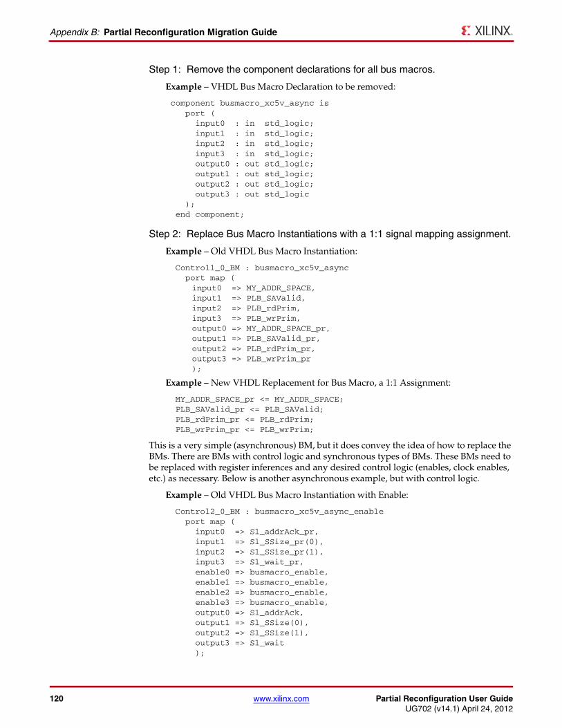
120 www.xilinx.com Partial Reconfiguration User GuideUG702 (v14.1) April 24, 2012
Appendix B: Partial Reconfiguration Migration Guide
Step 1: Remove the component declarations for all bus macros.
Example – VHDL Bus Macro Declaration to be removed:
component busmacro_xc5v_async is port ( input0 : in std_logic; input1 : in std_logic; input2 : in std_logic; input3 : in std_logic; output0 : out std_logic; output1 : out std_logic; output2 : out std_logic; output3 : out std_logic ); end component;
Step 2: Replace Bus Macro Instantiations with a 1:1 signal mapping assignment.
Example – Old VHDL Bus Macro Instantiation:
Control1_0_BM : busmacro_xc5v_async port map (
input0 => MY_ADDR_SPACE, input1 => PLB_SAValid, input2 => PLB_rdPrim, input3 => PLB_wrPrim, output0 => MY_ADDR_SPACE_pr, output1 => PLB_SAValid_pr, output2 => PLB_rdPrim_pr, output3 => PLB_wrPrim_pr
);
Example – New VHDL Replacement for Bus Macro, a 1:1 Assignment:
MY_ADDR_SPACE_pr <= MY_ADDR_SPACE; PLB_SAValid_pr <= PLB_SAValid; PLB_rdPrim_pr <= PLB_rdPrim; PLB_wrPrim_pr <= PLB_wrPrim;
This is a very simple (asynchronous) BM, but it does convey the idea of how to replace the BMs. There are BMs with control logic and synchronous types of BMs. These BMs need to be replaced with register inferences and any desired control logic (enables, clock enables, etc.) as necessary. Below is another asynchronous example, but with control logic.
Example – Old VHDL Bus Macro Instantiation with Enable:
Control2_0_BM : busmacro_xc5v_async_enable port map ( input0 => Sl_addrAck_pr, input1 => Sl_SSize_pr(0), input2 => Sl_SSize_pr(1), input3 => Sl_wait_pr, enable0 => busmacro_enable, enable1 => busmacro_enable, enable2 => busmacro_enable, enable3 => busmacro_enable, output0 => Sl_addrAck, output1 => Sl_SSize(0), output2 => Sl_SSize(1), output3 => Sl_wait );
Partial Reconfiguration User Guide www.xilinx.com 121UG702 (v14.1) April 24, 2012
Migrating a Design
Example – New VHDL Replacement for Bus Macro with Enable:
Sl_addrAck <= Sl_addrAck_pr and busmacro_enable; Sl_SSize(0) <= Sl_SSize_pr(0) and busmacro_enable; Sl_SSize(1) <= Sl_SSize_pr(1) and busmacro_enable; Sl_wait <= Sl_wait_pr and busmacro_enable;
Redefine Bus Macros
The BMs can be replaced with a newly created netlist that matches the BMs old name. This method is recommended for Synchronous Bus Macros, as they can be used directly for logic decoupling needs. The task of re-validating the PR solution is greatly simplified, as the logic design will remain equivalent.
Create a netlist with the same interface as a BM from HDL, with the internal assignments defined as desired. During synthesis, ensure that I/O buffer insertion is disabled (for example, in XST the option is named ‘Add I/O Buffers [-iobuf]’).
Note: These logic modules will exist in static logic, regardless of whether or not the replaced BM was an input or an output of a Reconfigurable Partition.
Example – VHDL Bus Macro Redefined for ‘busmacro_xc5v_async’:
library IEEE;use IEEE.STD_LOGIC_1164.ALL;entity busmacro_xc5v_async is Port ( input0 : in STD_LOGIC; input1 : in STD_LOGIC; input2 : in STD_LOGIC; input3 : in STD_LOGIC; output0 : out STD_LOGIC; output1 : out STD_LOGIC; output2 : out STD_LOGIC; output3 : out STD_LOGIC);end busmacro_xc5v_async;architecture Behavioral of busmacro_xc5v_async isbeginoutput0 <= input0;output1 <= input1;output2 <= input2;output3 <= input3;
end Behavioral;
While this may seem like more work up front, if a design has hundreds of BMs throughout, this will make the conversion much easier and quicker, as each of those instances do not have to be changed. As you begin to redefine these bus macros, any problems with the module can be fixed and the change will be consistent with all BMs of that type throughout the design. Below is another asynchronous example, but with control logic.
122 www.xilinx.com Partial Reconfiguration User GuideUG702 (v14.1) April 24, 2012
Appendix B: Partial Reconfiguration Migration Guide
Example – VHDL Bus Macro with Enable Redefined for ‘busmacro_xc5v_async_enable’:
library IEEE;use IEEE.STD_LOGIC_1164.ALL;entity busmacro_xc5v_async_enable is Port ( input0 : in STD_LOGIC; input1 : in STD_LOGIC; input2 : in STD_LOGIC; input3 : in STD_LOGIC; enable0 : in STD_LOGIC; enable1 : in STD_LOGIC; enable2 : in STD_LOGIC; enable3 : in STD_LOGIC; output0 : out STD_LOGIC; output1 : out STD_LOGIC; output2 : out STD_LOGIC; output3 : out STD_LOGIC);end busmacro_xc5v_async_enable;architecture Behavioral of busmacro_xc5v_async_enable isbeginoutput0 <= input0 and enable0;output1 <= input1 and enable1;output2 <= input2 and enable2;output3 <= input3 and enable3;
end Behavioral;
Verilog Bus Macro Removal
The flow is exactly the same as the VHDL flow, except the Verilog flow does not have module declarations. Follow the VHDL flow but use Verilog syntax.
Create a PlanAhead Project in 14.1 To create this project, follow the instructions in Creating a Partial Reconfiguration Project in Chapter 4.
If the Redefine Bus Macro process was used, then the BM replacement netlists need to be included as static logic source files for PlanAhead when the project is created.
SummaryDesigns created and implemented with the Modular Design Early Access Partial Reconfiguration tools can be easily converted to the Partition-based ISE 14 solution. Bus macros must be removed or replaced, decoupling logic should be considered, and Modular Design-specific options can be removed. In no time at all you will be implementing designs with the latest Partial Reconfiguration software.
Partial Reconfiguration User Guide www.xilinx.com 123UG702 (v14.1) April 24, 2012
Appendix C
Additional Resources
To find additional documentation, see the Xilinx website at:
http://www.xilinx.com/literature
To search the Answer Database of silicon, software, and IP questions and answers, or to create a technical support WebCase, see the Xilinx website at:
http://www.xilinx.com/support
For additional information to help build Partial Reconfiguration designs, see:
• Partial Reconfiguration of Virtex FPGAs in ISE 12 (WP374): http://www.xilinx.com/support/documentation/white_papers/wp374_Partial_Reconfig_Virtex_FPGAs.pdf
• Overview of the Partial Reconfiguration Flow (UG743): http://www.xilinx.com/support/documentation/sw_manuals/xilinx13_4/PlanAhead_Tutorial_Partial_Reconfiguration.pdf
• Partial Reconfiguration of a Processor Peripheral Tutorial (UG744): http://www.xilinx.com/support/documentation/sw_manuals/xilinx13_4/PlanAhead_Tutorial_Reconfigurable_Processor.pdf
• Fast Configuration of PCI Express Technology through Partial Reconfiguration (XAPP883) http://www.xilinx.com/support/documentation/application_notes/xapp883_Fast_Config_PCIe.pdf
• PRC/EPRC: Data Integrity and Security Controller for Partial Reconfiguration (XAPP887): http://www.xilinx.com/support/documentation/application_notes/xapp887_PRC_EPRC.pdf
• Differencing Method for Partial Reconfiguration (XAPP290): http://www.xilinx.com/support/documentation/application_notes/xapp290.pdf
• Hierarchical Design Methodology Guide (UG748): http://www.xilinx.com/support/documentation/sw_manuals/xilinx13_4/Hierarchical_Design_Methodolgy_Guide.pdf
• Repeatable Results with Design Preservation (WP362): http://www.xilinx.com/support/documentation/white_papers/wp362.pdf
• PlanAhead User Guide (UG632): http://www.xilinx.com/support/documentation/sw_manuals/xilinx13_4/PlanAhead_UserGuide.pdf
• Command Line Tools User Guide (UG628): http://www.xilinx.com/support/documentation/sw_manuals/xilinx13_4/devref.pdf
• Constraints Guide (UG625): http://www.xilinx.com/support/documentation/sw_manuals/xilinx13_4/cgd.pdf
• 7 Series FPGAs Configuration User Guide (UG470):http://www.xilinx.com/support/documentation/user_guides/ug470_7Series_Config.pdf
124 www.xilinx.com Partial Reconfiguration User GuideUG702 (v14.1) April 24, 2012
Appendix C: Additional Resources
• Virtex-6 FPGA Configuration User Guide (UG360):http://www.xilinx.com/support/documentation/user_guides/ug360.pdf
• Virtex-5 FPGA Configuration User Guide (UG191):http://www.xilinx.com/support/documentation/user_guides/ug191.pdf
• Virtex-4 FPGA Configuration User Guide (UG071): http://www.xilinx.com/support/documentation/user_guides/ug071.pdf
• XST User Guide for Virtex-4, Virtex-5, Spartan-3, and Newer CPLD Devices (UG627): http://www.xilinx.com/support/documentation/sw_manuals/xilinx13_4/xst.pdf
• XST User Guide for Virtex-6, Spartan-6, and 7 Series Devices (UG687): http://www.xilinx.com/support/documentation/sw_manuals/xilinx13_4/xst_v6s6.pdf


