122
R LogiCORE™ IP MOST ® NIC v1.4 User Guide UG336 September 19, 2008 Discontinued IP

R
LogiCORE™ IPMOST® NIC v1.4
User GuideUG336 September 19, 2008
Discontinued IP
www.xilinx.com MOST NIC v1.4 User GuideUG336 September 19, 2008
Xilinx is disclosing this Document and Intellectual Property (hereinafter “the Design”) to you for use in the development of designs to operate on, or interface with Xilinx FPGAs. Except as stated herein, none of the Design may be copied, reproduced, distributed, republished, downloaded, displayed, posted, or transmitted in any form or by any means including, but not limited to, electronic, mechanical, photocopying, recording, or otherwise, without the prior written consent of Xilinx. Any unauthorized use of the Design may violate copyright laws, trademark laws, the laws of privacy and publicity, and communications regulations and statutes.
Xilinx does not assume any liability arising out of the application or use of the Design; nor does Xilinx convey any license under its patents, copyrights, or any rights of others. You are responsible for obtaining any rights you may require for your use or implementation of the Design. Xilinx reserves the right to make changes, at any time, to the Design as deemed desirable in the sole discretion of Xilinx. Xilinx assumes no obligation to correct any errors contained herein or to advise you of any correction if such be made. Xilinx will not assume any liability for the accuracy or correctness of any engineering or technical support or assistance provided to you in connection with the Design.
THE DESIGN IS PROVIDED “AS IS” WITH ALL FAULTS, AND THE ENTIRE RISK AS TO ITS FUNCTION AND IMPLEMENTATION IS WITH YOU. YOU ACKNOWLEDGE AND AGREE THAT YOU HAVE NOT RELIED ON ANY ORAL OR WRITTEN INFORMATION OR ADVICE, WHETHER GIVEN BY XILINX, OR ITS AGENTS OR EMPLOYEES. XILINX MAKES NO OTHER WARRANTIES, WHETHER EXPRESS, IMPLIED, OR STATUTORY, REGARDING THE DESIGN, INCLUDING ANY WARRANTIES OF MERCHANTABILITY, FITNESS FOR A PARTICULAR PURPOSE, TITLE, AND NONINFRINGEMENT OF THIRD-PARTY RIGHTS.
IN NO EVENT WILL XILINX BE LIABLE FOR ANY CONSEQUENTIAL, INDIRECT, EXEMPLARY, SPECIAL, OR INCIDENTAL DAMAGES, INCLUDING ANY LOST DATA AND LOST PROFITS, ARISING FROM OR RELATING TO YOUR USE OF THE DESIGN, EVEN IF YOU HAVE BEEN ADVISED OF THE POSSIBILITY OF SUCH DAMAGES. THE TOTAL CUMULATIVE LIABILITY OF XILINX IN CONNECTION WITH YOUR USE OF THE DESIGN, WHETHER IN CONTRACT OR TORT OR OTHERWISE, WILL IN NO EVENT EXCEED THE AMOUNT OF FEES PAID BY YOU TO XILINX HEREUNDER FOR USE OF THE DESIGN. YOU ACKNOWLEDGE THAT THE FEES, IF ANY, REFLECT THE ALLOCATION OF RISK SET FORTH IN THIS AGREEMENT AND THAT XILINX WOULD NOT MAKE AVAILABLE THE DESIGN TO YOU WITHOUT THESE LIMITATIONS OF LIABILITY.
The Design is not designed or intended for use in the development of on-line control equipment in hazardous environments requiring fail-safe controls, such as in the operation of nuclear facilities, aircraft navigation or communications systems, air traffic control, life support, or weapons systems (“High-Risk Applications”). Xilinx specifically disclaims any express or implied warranties of fitness for such High-Risk Applications. You represent that use of the Design in such High-Risk Applications is fully at your risk.
© 2007-2008 Xilinx, Inc. All rights reserved. XILINX, the Xilinx logo, and other designated brands included herein are trademarks of Xilinx, Inc. All other trademarks are the property of their respective owners.
Revision HistoryThe following table shows the revision history for this document.
Date Version Revision
05/17/07 1.1 Initial Xilinx release
08/08/07 1.2 Support for Spartan-3A DSP added.
04/25/08 1.3 No functional change.
09/19/08 1.4 Automatic lock detection enhancement.
R
Discontinued IP

MOST NIC v1.4 User Guide www.xilinx.comUG336 September 19, 2008
Schedule of Figures . . . . . . . . . . . . . . . . . . . . . . . . . . . . . . . . . . . . . . . . . . . . . . . . . . . . . . . . . . 7
Schedule of Tables . . . . . . . . . . . . . . . . . . . . . . . . . . . . . . . . . . . . . . . . . . . . . . . . . . . . . . . . . . . 9
Preface: About This GuideContents . . . . . . . . . . . . . . . . . . . . . . . . . . . . . . . . . . . . . . . . . . . . . . . . . . . . . . . . . . . . . . . . . . . . 13Additional Resources . . . . . . . . . . . . . . . . . . . . . . . . . . . . . . . . . . . . . . . . . . . . . . . . . . . . . . . 14Conventions . . . . . . . . . . . . . . . . . . . . . . . . . . . . . . . . . . . . . . . . . . . . . . . . . . . . . . . . . . . . . . . . 14
Typographical . . . . . . . . . . . . . . . . . . . . . . . . . . . . . . . . . . . . . . . . . . . . . . . . . . . . . . . . . . . . 14Online Document . . . . . . . . . . . . . . . . . . . . . . . . . . . . . . . . . . . . . . . . . . . . . . . . . . . . . . . . . 15
Chapter 1: IntroductionAbout the Core . . . . . . . . . . . . . . . . . . . . . . . . . . . . . . . . . . . . . . . . . . . . . . . . . . . . . . . . . . . . . . 17Recommended Design Experience . . . . . . . . . . . . . . . . . . . . . . . . . . . . . . . . . . . . . . . . . . . 17Additional Core Resources . . . . . . . . . . . . . . . . . . . . . . . . . . . . . . . . . . . . . . . . . . . . . . . . . . 17Technical Support. . . . . . . . . . . . . . . . . . . . . . . . . . . . . . . . . . . . . . . . . . . . . . . . . . . . . . . . . . . 18Feedback. . . . . . . . . . . . . . . . . . . . . . . . . . . . . . . . . . . . . . . . . . . . . . . . . . . . . . . . . . . . . . . . . . . . 18
Core . . . . . . . . . . . . . . . . . . . . . . . . . . . . . . . . . . . . . . . . . . . . . . . . . . . . . . . . . . . . . . . . . . . . 18Document . . . . . . . . . . . . . . . . . . . . . . . . . . . . . . . . . . . . . . . . . . . . . . . . . . . . . . . . . . . . . . . 18
Chapter 2: Core ArchitectureModule Architecture . . . . . . . . . . . . . . . . . . . . . . . . . . . . . . . . . . . . . . . . . . . . . . . . . . . . . . . . 19
Receive Recovery . . . . . . . . . . . . . . . . . . . . . . . . . . . . . . . . . . . . . . . . . . . . . . . . . . . . . . . . . 20Receive MAC . . . . . . . . . . . . . . . . . . . . . . . . . . . . . . . . . . . . . . . . . . . . . . . . . . . . . . . . . . . . 20Receive Routing Engine . . . . . . . . . . . . . . . . . . . . . . . . . . . . . . . . . . . . . . . . . . . . . . . . . . . 20Clocking and Reset . . . . . . . . . . . . . . . . . . . . . . . . . . . . . . . . . . . . . . . . . . . . . . . . . . . . . . . 21MOST Controller Design Parameters . . . . . . . . . . . . . . . . . . . . . . . . . . . . . . . . . . . . . . . . 22
Core Interfaces . . . . . . . . . . . . . . . . . . . . . . . . . . . . . . . . . . . . . . . . . . . . . . . . . . . . . . . . . . . . . . 22MOST NIC Interfaces . . . . . . . . . . . . . . . . . . . . . . . . . . . . . . . . . . . . . . . . . . . . . . . . . . . . . 22Host Interface . . . . . . . . . . . . . . . . . . . . . . . . . . . . . . . . . . . . . . . . . . . . . . . . . . . . . . . . . . . . 23Streaming Port Interface . . . . . . . . . . . . . . . . . . . . . . . . . . . . . . . . . . . . . . . . . . . . . . . . . . . 25
Chapter 3: MOST Link Layer BackgroundIntroduction . . . . . . . . . . . . . . . . . . . . . . . . . . . . . . . . . . . . . . . . . . . . . . . . . . . . . . . . . . . . . . . . 31
Ring Topology . . . . . . . . . . . . . . . . . . . . . . . . . . . . . . . . . . . . . . . . . . . . . . . . . . . . . . . . . . . 32Modulation and Clocking . . . . . . . . . . . . . . . . . . . . . . . . . . . . . . . . . . . . . . . . . . . . . . . . . . . 33
Frame Encoding . . . . . . . . . . . . . . . . . . . . . . . . . . . . . . . . . . . . . . . . . . . . . . . . . . . . . . . . . . 33Master Clock . . . . . . . . . . . . . . . . . . . . . . . . . . . . . . . . . . . . . . . . . . . . . . . . . . . . . . . . . . . . . 33
Frame Format . . . . . . . . . . . . . . . . . . . . . . . . . . . . . . . . . . . . . . . . . . . . . . . . . . . . . . . . . . . . . . . 33Header Field . . . . . . . . . . . . . . . . . . . . . . . . . . . . . . . . . . . . . . . . . . . . . . . . . . . . . . . . . . . . . 34Synchronous Field . . . . . . . . . . . . . . . . . . . . . . . . . . . . . . . . . . . . . . . . . . . . . . . . . . . . . . . . 34Asynchronous Field . . . . . . . . . . . . . . . . . . . . . . . . . . . . . . . . . . . . . . . . . . . . . . . . . . . . . . . 34
Table of Contents
Discontinued IP

www.xilinx.com MOST NIC v1.4 User GuideUG336 September 19, 2008
R
Control Message Field . . . . . . . . . . . . . . . . . . . . . . . . . . . . . . . . . . . . . . . . . . . . . . . . . . . . . 34Trailer . . . . . . . . . . . . . . . . . . . . . . . . . . . . . . . . . . . . . . . . . . . . . . . . . . . . . . . . . . . . . . . . . . . 35Block and Super Block . . . . . . . . . . . . . . . . . . . . . . . . . . . . . . . . . . . . . . . . . . . . . . . . . . . . . 36
Synchronous Channels . . . . . . . . . . . . . . . . . . . . . . . . . . . . . . . . . . . . . . . . . . . . . . . . . . . . . . 37Application Example . . . . . . . . . . . . . . . . . . . . . . . . . . . . . . . . . . . . . . . . . . . . . . . . . . . . . . 38
Asynchronous Channel . . . . . . . . . . . . . . . . . . . . . . . . . . . . . . . . . . . . . . . . . . . . . . . . . . . . . 40Packet Format . . . . . . . . . . . . . . . . . . . . . . . . . . . . . . . . . . . . . . . . . . . . . . . . . . . . . . . . . . . . 40Arbitration. . . . . . . . . . . . . . . . . . . . . . . . . . . . . . . . . . . . . . . . . . . . . . . . . . . . . . . . . . . . . . . 41
Control Message Channel . . . . . . . . . . . . . . . . . . . . . . . . . . . . . . . . . . . . . . . . . . . . . . . . . . . 41Format . . . . . . . . . . . . . . . . . . . . . . . . . . . . . . . . . . . . . . . . . . . . . . . . . . . . . . . . . . . . . . . . . . 41Arbitration. . . . . . . . . . . . . . . . . . . . . . . . . . . . . . . . . . . . . . . . . . . . . . . . . . . . . . . . . . . . . . . 43Checksum . . . . . . . . . . . . . . . . . . . . . . . . . . . . . . . . . . . . . . . . . . . . . . . . . . . . . . . . . . . . . . . 43Transmission Status . . . . . . . . . . . . . . . . . . . . . . . . . . . . . . . . . . . . . . . . . . . . . . . . . . . . . . . 43Control Message Types . . . . . . . . . . . . . . . . . . . . . . . . . . . . . . . . . . . . . . . . . . . . . . . . . . . . 45Normal Control Message . . . . . . . . . . . . . . . . . . . . . . . . . . . . . . . . . . . . . . . . . . . . . . . . . . 45Allocation Message . . . . . . . . . . . . . . . . . . . . . . . . . . . . . . . . . . . . . . . . . . . . . . . . . . . . . . . 46Deallocation Message . . . . . . . . . . . . . . . . . . . . . . . . . . . . . . . . . . . . . . . . . . . . . . . . . . . . . 48Remote Read Message . . . . . . . . . . . . . . . . . . . . . . . . . . . . . . . . . . . . . . . . . . . . . . . . . . . . . 50Remote Write Message . . . . . . . . . . . . . . . . . . . . . . . . . . . . . . . . . . . . . . . . . . . . . . . . . . . . 52Get Source Message . . . . . . . . . . . . . . . . . . . . . . . . . . . . . . . . . . . . . . . . . . . . . . . . . . . . . . . 53Source and Destination Addresses . . . . . . . . . . . . . . . . . . . . . . . . . . . . . . . . . . . . . . . . . . 54Network Information . . . . . . . . . . . . . . . . . . . . . . . . . . . . . . . . . . . . . . . . . . . . . . . . . . . . . 55
Synchronous Channel Resource Mechanism . . . . . . . . . . . . . . . . . . . . . . . . . . . . . . . . . 57Startup and Synchronization . . . . . . . . . . . . . . . . . . . . . . . . . . . . . . . . . . . . . . . . . . . . . . . . 57
Lock and Unlock . . . . . . . . . . . . . . . . . . . . . . . . . . . . . . . . . . . . . . . . . . . . . . . . . . . . . . . . . 57Bypass . . . . . . . . . . . . . . . . . . . . . . . . . . . . . . . . . . . . . . . . . . . . . . . . . . . . . . . . . . . . . . . . . . 58Unlocked Slave . . . . . . . . . . . . . . . . . . . . . . . . . . . . . . . . . . . . . . . . . . . . . . . . . . . . . . . . . . . 58Unlocked Master . . . . . . . . . . . . . . . . . . . . . . . . . . . . . . . . . . . . . . . . . . . . . . . . . . . . . . . . . 58Device Wakeup . . . . . . . . . . . . . . . . . . . . . . . . . . . . . . . . . . . . . . . . . . . . . . . . . . . . . . . . . . 59
Chapter 4: Generating the CoreGraphical User Interface . . . . . . . . . . . . . . . . . . . . . . . . . . . . . . . . . . . . . . . . . . . . . . . . . . . . 61
Component Name . . . . . . . . . . . . . . . . . . . . . . . . . . . . . . . . . . . . . . . . . . . . . . . . . . . . . . . . 61OPB Address Support . . . . . . . . . . . . . . . . . . . . . . . . . . . . . . . . . . . . . . . . . . . . . . . . . . . . . 63
Output Generation . . . . . . . . . . . . . . . . . . . . . . . . . . . . . . . . . . . . . . . . . . . . . . . . . . . . . . . . . . 63
Chapter 5: Constraining the CoreRequired Constraints. . . . . . . . . . . . . . . . . . . . . . . . . . . . . . . . . . . . . . . . . . . . . . . . . . . . . . . . 65
Device, Package, and Speedgrade Selection . . . . . . . . . . . . . . . . . . . . . . . . . . . . . . . . . . 65I/O Location Constraints . . . . . . . . . . . . . . . . . . . . . . . . . . . . . . . . . . . . . . . . . . . . . . . . . . 65Placement Constraints . . . . . . . . . . . . . . . . . . . . . . . . . . . . . . . . . . . . . . . . . . . . . . . . . . . . . 65Timing Constraints . . . . . . . . . . . . . . . . . . . . . . . . . . . . . . . . . . . . . . . . . . . . . . . . . . . . . . . 65
Chapter 6: Configuration SpaceSummary . . . . . . . . . . . . . . . . . . . . . . . . . . . . . . . . . . . . . . . . . . . . . . . . . . . . . . . . . . . . . . . . . . . 67
Reserved Bits. . . . . . . . . . . . . . . . . . . . . . . . . . . . . . . . . . . . . . . . . . . . . . . . . . . . . . . . . . . . . 67Byte Enable Support . . . . . . . . . . . . . . . . . . . . . . . . . . . . . . . . . . . . . . . . . . . . . . . . . . . . . . 67
MOST Controller Registers . . . . . . . . . . . . . . . . . . . . . . . . . . . . . . . . . . . . . . . . . . . . . . . . . 70Version Register . . . . . . . . . . . . . . . . . . . . . . . . . . . . . . . . . . . . . . . . . . . . . . . . . . . . . . . . . . 70
Discontinued IP

www.xilinx.com MOST NIC v1.4 User GuideUG336 September 19, 2008
R
Soft Reset Register . . . . . . . . . . . . . . . . . . . . . . . . . . . . . . . . . . . . . . . . . . . . . . . . . . . . . . . . 70Mode Select Register . . . . . . . . . . . . . . . . . . . . . . . . . . . . . . . . . . . . . . . . . . . . . . . . . . . . . . 72Status Register (SR) . . . . . . . . . . . . . . . . . . . . . . . . . . . . . . . . . . . . . . . . . . . . . . . . . . . . . . . 75Channel Control Register . . . . . . . . . . . . . . . . . . . . . . . . . . . . . . . . . . . . . . . . . . . . . . . . . . 76Maximum and Current Position and Delay Register . . . . . . . . . . . . . . . . . . . . . . . . . . . 77Logical Address Register . . . . . . . . . . . . . . . . . . . . . . . . . . . . . . . . . . . . . . . . . . . . . . . . . . 78Alternate Address Register. . . . . . . . . . . . . . . . . . . . . . . . . . . . . . . . . . . . . . . . . . . . . . . . . 78Group Address Register . . . . . . . . . . . . . . . . . . . . . . . . . . . . . . . . . . . . . . . . . . . . . . . . . . . 79Flush Control Register . . . . . . . . . . . . . . . . . . . . . . . . . . . . . . . . . . . . . . . . . . . . . . . . . . . . . 79Transmit Buffer Error Register . . . . . . . . . . . . . . . . . . . . . . . . . . . . . . . . . . . . . . . . . . . . . . 80Receive Buffer Error Register . . . . . . . . . . . . . . . . . . . . . . . . . . . . . . . . . . . . . . . . . . . . . . . 81
MOST Control Processing . . . . . . . . . . . . . . . . . . . . . . . . . . . . . . . . . . . . . . . . . . . . . . . . . . . 82Message Retry Count and Delay Register . . . . . . . . . . . . . . . . . . . . . . . . . . . . . . . . . . . . 82Control Transmit Status Register . . . . . . . . . . . . . . . . . . . . . . . . . . . . . . . . . . . . . . . . . . . . 83Control Receive Status Register . . . . . . . . . . . . . . . . . . . . . . . . . . . . . . . . . . . . . . . . . . . . . 83Control Transmit FIFO . . . . . . . . . . . . . . . . . . . . . . . . . . . . . . . . . . . . . . . . . . . . . . . . . . . . 84Control Transmit Response FIFO . . . . . . . . . . . . . . . . . . . . . . . . . . . . . . . . . . . . . . . . . . . 86Control Receive FIFO . . . . . . . . . . . . . . . . . . . . . . . . . . . . . . . . . . . . . . . . . . . . . . . . . . . . . 87
Interrupt Control and Status Registers . . . . . . . . . . . . . . . . . . . . . . . . . . . . . . . . . . . . . . . 88MOST Interrupt Control and Status Registers. . . . . . . . . . . . . . . . . . . . . . . . . . . . . . . . . 89Buffer Interrupt Control and Status Registers . . . . . . . . . . . . . . . . . . . . . . . . . . . . . . . . . 92
Routing Table. . . . . . . . . . . . . . . . . . . . . . . . . . . . . . . . . . . . . . . . . . . . . . . . . . . . . . . . . . . . . . . 94Common Routing Table . . . . . . . . . . . . . . . . . . . . . . . . . . . . . . . . . . . . . . . . . . . . . . . . . . . 94Logical Channel Enable . . . . . . . . . . . . . . . . . . . . . . . . . . . . . . . . . . . . . . . . . . . . . . . . . . . . 96Slave Active Register 1 . . . . . . . . . . . . . . . . . . . . . . . . . . . . . . . . . . . . . . . . . . . . . . . . . . . . 97Slave Active Register 2 . . . . . . . . . . . . . . . . . . . . . . . . . . . . . . . . . . . . . . . . . . . . . . . . . . . . 97Master Allocation Table . . . . . . . . . . . . . . . . . . . . . . . . . . . . . . . . . . . . . . . . . . . . . . . . . . . 98
Streaming Port MMR . . . . . . . . . . . . . . . . . . . . . . . . . . . . . . . . . . . . . . . . . . . . . . . . . . . . . . . 99MOST PLL Control Registers. . . . . . . . . . . . . . . . . . . . . . . . . . . . . . . . . . . . . . . . . . . . . . . 100
PLL Reference Count Register . . . . . . . . . . . . . . . . . . . . . . . . . . . . . . . . . . . . . . . . . . . . . 100External PLL Reset Count . . . . . . . . . . . . . . . . . . . . . . . . . . . . . . . . . . . . . . . . . . . . . . . . . 100
Transmit / Receive Buffer . . . . . . . . . . . . . . . . . . . . . . . . . . . . . . . . . . . . . . . . . . . . . . . . . . 101Transmit Buffer . . . . . . . . . . . . . . . . . . . . . . . . . . . . . . . . . . . . . . . . . . . . . . . . . . . . . . . . . 101Receive Buffer . . . . . . . . . . . . . . . . . . . . . . . . . . . . . . . . . . . . . . . . . . . . . . . . . . . . . . . . . . . 103
Chapter 7: Programming the CoreConfiguring the Controller . . . . . . . . . . . . . . . . . . . . . . . . . . . . . . . . . . . . . . . . . . . . . . . . . 107
For a Ring (Slave) . . . . . . . . . . . . . . . . . . . . . . . . . . . . . . . . . . . . . . . . . . . . . . . . . . . . . . . . 107Configuring the Controller . . . . . . . . . . . . . . . . . . . . . . . . . . . . . . . . . . . . . . . . . . . . . . . . . 108
For a Ring (Master) . . . . . . . . . . . . . . . . . . . . . . . . . . . . . . . . . . . . . . . . . . . . . . . . . . . . . . 108Configuring a Transmit Synchronous Channel . . . . . . . . . . . . . . . . . . . . . . . . . . . . . 108Transmitting Synchronous or Asynchronous Data . . . . . . . . . . . . . . . . . . . . . . . . . . 109Receiving Synchronous Data . . . . . . . . . . . . . . . . . . . . . . . . . . . . . . . . . . . . . . . . . . . . . . . 109Receiving Asynchronous Data . . . . . . . . . . . . . . . . . . . . . . . . . . . . . . . . . . . . . . . . . . . . . . 110Flushing a Synchronous or Asynchronous Buffer . . . . . . . . . . . . . . . . . . . . . . . . . . . 111
To Remove the Data in the Current Stream . . . . . . . . . . . . . . . . . . . . . . . . . . . . . . . . . . 111Due to an Overflow or Underflow Condition . . . . . . . . . . . . . . . . . . . . . . . . . . . . . . . . 111
Using the Streaming Ports . . . . . . . . . . . . . . . . . . . . . . . . . . . . . . . . . . . . . . . . . . . . . . . . . . 112Control Message Procedure . . . . . . . . . . . . . . . . . . . . . . . . . . . . . . . . . . . . . . . . . . . . . . . . 112
Discontinued IP

MOST NIC v1.4 User Guide www.xilinx.comUG336 September 19, 2008
R
Transmit Message Procedure . . . . . . . . . . . . . . . . . . . . . . . . . . . . . . . . . . . . . . . . . . . . . . 112Response Message Procedure . . . . . . . . . . . . . . . . . . . . . . . . . . . . . . . . . . . . . . . . . . . . . 113Receive Message Procedure . . . . . . . . . . . . . . . . . . . . . . . . . . . . . . . . . . . . . . . . . . . . . . . 113
Flushing a Control Buffer due to a Deadlock Condition . . . . . . . . . . . . . . . . . . . . . 114Controlling the State of Light on the Ring . . . . . . . . . . . . . . . . . . . . . . . . . . . . . . . . . . 114
Stopping the Transmission of Light on the Ring. . . . . . . . . . . . . . . . . . . . . . . . . . . . . . 114Starting the Reception of Light from the Ring . . . . . . . . . . . . . . . . . . . . . . . . . . . . . . . . 114Starting the Transmission of Light to the Ring . . . . . . . . . . . . . . . . . . . . . . . . . . . . . . . 115
Configuring the Controller for Test Modes . . . . . . . . . . . . . . . . . . . . . . . . . . . . . . . . . 115Ring Break Diagnostics . . . . . . . . . . . . . . . . . . . . . . . . . . . . . . . . . . . . . . . . . . . . . . . . . . . 115For Loopback . . . . . . . . . . . . . . . . . . . . . . . . . . . . . . . . . . . . . . . . . . . . . . . . . . . . . . . . . . . 115
Special Considerations . . . . . . . . . . . . . . . . . . . . . . . . . . . . . . . . . . . . . . . . . . . . . . . . . . . . . 116Disabling MENA for an Active Core . . . . . . . . . . . . . . . . . . . . . . . . . . . . . . . . . . . . . . . 116SBD Change . . . . . . . . . . . . . . . . . . . . . . . . . . . . . . . . . . . . . . . . . . . . . . . . . . . . . . . . . . . . 116Multicast Addressing for Control Messages . . . . . . . . . . . . . . . . . . . . . . . . . . . . . . . . . 117Using the Core in Loopback . . . . . . . . . . . . . . . . . . . . . . . . . . . . . . . . . . . . . . . . . . . . . . . 117
Glossary of Terms. . . . . . . . . . . . . . . . . . . . . . . . . . . . . . . . . . . . . . . . . . . . . . . . . . . . . . . . . . 119
Discontinued IP
MOST NIC v1.4 User Guide www.xilinx.comUG336 September 19, 2008
Chapter 2: Core ArchitectureFigure 2-1: MOST NIC Block Diagram . . . . . . . . . . . . . . . . . . . . . . . . . . . . . . . . . . . . . . . . . . 19Figure 2-2: MOST Core Interfaces. . . . . . . . . . . . . . . . . . . . . . . . . . . . . . . . . . . . . . . . . . . . . . . 22Figure 2-3: Receive Streaming Port Read. . . . . . . . . . . . . . . . . . . . . . . . . . . . . . . . . . . . . . . . . 30Figure 2-4: Receive Streaming Port Write . . . . . . . . . . . . . . . . . . . . . . . . . . . . . . . . . . . . . . . . 30
Chapter 3: MOST Link Layer BackgroundFigure 3-1: MOST Ring Topology. . . . . . . . . . . . . . . . . . . . . . . . . . . . . . . . . . . . . . . . . . . . . . . 32Figure 3-2: MOST Frame Format . . . . . . . . . . . . . . . . . . . . . . . . . . . . . . . . . . . . . . . . . . . . . . . . 33Figure 3-3: MOST Block and Super Block. . . . . . . . . . . . . . . . . . . . . . . . . . . . . . . . . . . . . . . . 37Figure 3-4: Synchronous Application Example . . . . . . . . . . . . . . . . . . . . . . . . . . . . . . . . . . . 38Figure 3-5: Asynchronous Packet Format . . . . . . . . . . . . . . . . . . . . . . . . . . . . . . . . . . . . . . . . 40Figure 3-6: Control Message Format . . . . . . . . . . . . . . . . . . . . . . . . . . . . . . . . . . . . . . . . . . . . . 42Figure 3-7: Transmission Status Format. . . . . . . . . . . . . . . . . . . . . . . . . . . . . . . . . . . . . . . . . . 44Figure 3-8: Normal Message Format . . . . . . . . . . . . . . . . . . . . . . . . . . . . . . . . . . . . . . . . . . . . . 46Figure 3-9: Allocation Request Format. . . . . . . . . . . . . . . . . . . . . . . . . . . . . . . . . . . . . . . . . . . 47Figure 3-10: Allocation Response Format . . . . . . . . . . . . . . . . . . . . . . . . . . . . . . . . . . . . . . . . 47Figure 3-11: Deallocation Request Format. . . . . . . . . . . . . . . . . . . . . . . . . . . . . . . . . . . . . . . . 49Figure 3-12: Deallocation Response Format . . . . . . . . . . . . . . . . . . . . . . . . . . . . . . . . . . . . . . 49Figure 3-13: Remote Read Request Format . . . . . . . . . . . . . . . . . . . . . . . . . . . . . . . . . . . . . . . 51Figure 3-14: Remote Read Response Format . . . . . . . . . . . . . . . . . . . . . . . . . . . . . . . . . . . . . . 51Figure 3-15: Remote Write Request Format. . . . . . . . . . . . . . . . . . . . . . . . . . . . . . . . . . . . . . . 52Figure 3-16: Get Source Request Format . . . . . . . . . . . . . . . . . . . . . . . . . . . . . . . . . . . . . . . . . 53Figure 3-17: Get Source Response Format . . . . . . . . . . . . . . . . . . . . . . . . . . . . . . . . . . . . . . . . 54Figure 3-18: Network Information Format . . . . . . . . . . . . . . . . . . . . . . . . . . . . . . . . . . . . . . . 56
Chapter 4: Generating the CoreFigure 4-1: Main Screen. . . . . . . . . . . . . . . . . . . . . . . . . . . . . . . . . . . . . . . . . . . . . . . . . . . . . . . . 61
Schedule of Figures
Discontinued IP

www.xilinx.com MOST NIC v1.4 User GuideUG336 September 19, 2008
R
Discontinued IP

MOST NIC v1.4 User Guide www.xilinx.comUG336 September 19, 2008
Chapter 2: Core ArchitectureTable 2-1: MOST Ring Interface . . . . . . . . . . . . . . . . . . . . . . . . . . . . . . . . . . . . . . . . . . . . . . . . 23Table 2-2: MOST Host Interface . . . . . . . . . . . . . . . . . . . . . . . . . . . . . . . . . . . . . . . . . . . . . . . . 24Table 2-3: MOST Streaming Port Interface . . . . . . . . . . . . . . . . . . . . . . . . . . . . . . . . . . . . . . . 26
Chapter 3: MOST Link Layer BackgroundTable 3-1: Control Message Type . . . . . . . . . . . . . . . . . . . . . . . . . . . . . . . . . . . . . . . . . . . . . . . 43Table 3-2: Control Message Transmission Status. . . . . . . . . . . . . . . . . . . . . . . . . . . . . . . . . . 44Table 3-3: Allocation Response Status . . . . . . . . . . . . . . . . . . . . . . . . . . . . . . . . . . . . . . . . . . . 48Table 3-4: Deallocation Response Status . . . . . . . . . . . . . . . . . . . . . . . . . . . . . . . . . . . . . . . . . 50Table 3-5: Message Type Multicast Support . . . . . . . . . . . . . . . . . . . . . . . . . . . . . . . . . . . . . . 55
Chapter 4: Generating the CoreTable 4-1: Ingress / Egress Buffer Mapping. . . . . . . . . . . . . . . . . . . . . . . . . . . . . . . . . . . . . . . 62Table 4-2: Word Count Parameters . . . . . . . . . . . . . . . . . . . . . . . . . . . . . . . . . . . . . . . . . . . . . . 63Table 4-3: MOST NIC Controller Design Parameter . . . . . . . . . . . . . . . . . . . . . . . . . . . . . . . 63
Chapter 6: Configuration SpaceTable 6-1: Xilinx MOST Controller Register . . . . . . . . . . . . . . . . . . . . . . . . . . . . . . . . . . . . . . 67Table 6-2: Version Register . . . . . . . . . . . . . . . . . . . . . . . . . . . . . . . . . . . . . . . . . . . . . . . . . . . . . 70Table 6-3: Soft Reset Register . . . . . . . . . . . . . . . . . . . . . . . . . . . . . . . . . . . . . . . . . . . . . . . . . . . 71Table 6-4: Mode Select Register . . . . . . . . . . . . . . . . . . . . . . . . . . . . . . . . . . . . . . . . . . . . . . . . . 72Table 6-5: Status Register . . . . . . . . . . . . . . . . . . . . . . . . . . . . . . . . . . . . . . . . . . . . . . . . . . . . . . 75Table 6-6: Channel Control Register . . . . . . . . . . . . . . . . . . . . . . . . . . . . . . . . . . . . . . . . . . . . . 77Table 6-7: Maximum and Current Position and Delay Register . . . . . . . . . . . . . . . . . . . . . 77Table 6-8: Logical Address Register Description . . . . . . . . . . . . . . . . . . . . . . . . . . . . . . . . . . 78Table 6-9: Alternate Address Register . . . . . . . . . . . . . . . . . . . . . . . . . . . . . . . . . . . . . . . . . . . 78Table 6-10: Group Address Register . . . . . . . . . . . . . . . . . . . . . . . . . . . . . . . . . . . . . . . . . . . . . 79Table 6-11: Flush Control Register Description . . . . . . . . . . . . . . . . . . . . . . . . . . . . . . . . . . . 79Table 6-12: Transmit Buffer Error Register Bits . . . . . . . . . . . . . . . . . . . . . . . . . . . . . . . . . . . 80Table 6-13: Transmit Buffer Error Register . . . . . . . . . . . . . . . . . . . . . . . . . . . . . . . . . . . . . . . 81Table 6-14: Receive Buffer Error Register Bits . . . . . . . . . . . . . . . . . . . . . . . . . . . . . . . . . . . . 81Table 6-15: Receive Buffer Error Bit Description . . . . . . . . . . . . . . . . . . . . . . . . . . . . . . . . . . 82Table 6-16: Message Retry Count and Delay Register Description . . . . . . . . . . . . . . . . . . 82Table 6-17: Control Transmit Status Register Bit Description. . . . . . . . . . . . . . . . . . . . . . . 83Table 6-18: Control Receive Status Register Bit Description . . . . . . . . . . . . . . . . . . . . . . . . 83Table 6-19: Control Transmit FIFO Bit Description. . . . . . . . . . . . . . . . . . . . . . . . . . . . . . . . 84Table 6-20: Control TX MSG: First Word . . . . . . . . . . . . . . . . . . . . . . . . . . . . . . . . . . . . . . . . . 84Table 6-21: Control TX MSG: Second Word . . . . . . . . . . . . . . . . . . . . . . . . . . . . . . . . . . . . . . 84Table 6-22: Control TX MSG: Third through Sixth Word. . . . . . . . . . . . . . . . . . . . . . . . . . . 84
Schedule of Tables
Discontinued IP
www.xilinx.com MOST NIC v1.4 User GuideUG336 September 19, 2008
R
Table 6-23: Message Type Encoding and Actions . . . . . . . . . . . . . . . . . . . . . . . . . . . . . . . . . 85Table 6-24: Control Transmit Response FIFO Bit Description . . . . . . . . . . . . . . . . . . . . . . 86Table 6-25: Control TX Response MSG: First Word . . . . . . . . . . . . . . . . . . . . . . . . . . . . . . . 87Table 6-26: Control TX Response MSG: Second Word . . . . . . . . . . . . . . . . . . . . . . . . . . . . . 87Table 6-27: Control TX Response MSG: Third to Sixth Word . . . . . . . . . . . . . . . . . . . . . . . 87Table 6-28: Control TX Response MSG: Seventh Word . . . . . . . . . . . . . . . . . . . . . . . . . . . . 87Table 6-29: Control Receive FIFO Bit Description . . . . . . . . . . . . . . . . . . . . . . . . . . . . . . . . . 88Table 6-30: Control RX MSG: First Word . . . . . . . . . . . . . . . . . . . . . . . . . . . . . . . . . . . . . . . . . 88Table 6-31: Control RX MSG: Second Word . . . . . . . . . . . . . . . . . . . . . . . . . . . . . . . . . . . . . . 88Table 6-32: Control RX MSG: Third to Sixth Word . . . . . . . . . . . . . . . . . . . . . . . . . . . . . . . . 88Table 6-33: MOST Interrupt Register Bit Positions . . . . . . . . . . . . . . . . . . . . . . . . . . . . . . . . 90Table 6-34: MOST Interrupt Register . . . . . . . . . . . . . . . . . . . . . . . . . . . . . . . . . . . . . . . . . . . . 90Table 6-35: Buffer Interrupt Register bits . . . . . . . . . . . . . . . . . . . . . . . . . . . . . . . . . . . . . . . . 93Table 6-36: Common Routing Table . . . . . . . . . . . . . . . . . . . . . . . . . . . . . . . . . . . . . . . . . . . . . 94Table 6-37: Synchronous Routing Table Word Organization . . . . . . . . . . . . . . . . . . . . . . . 95Table 6-38: Synchronous Routing Table Bits . . . . . . . . . . . . . . . . . . . . . . . . . . . . . . . . . . . . . 95Table 6-39: Asynchronous Routing Table Word Organization . . . . . . . . . . . . . . . . . . . . . . 96Table 6-40: Asynchronous Routing Table Bit . . . . . . . . . . . . . . . . . . . . . . . . . . . . . . . . . . . . . 96Table 6-41: Logical Channel Enable Register Bits . . . . . . . . . . . . . . . . . . . . . . . . . . . . . . . . . 96Table 6-42: Logical Channel Enable Bit Description . . . . . . . . . . . . . . . . . . . . . . . . . . . . . . . 97Table 6-43: Slave Active Register 1 Bits . . . . . . . . . . . . . . . . . . . . . . . . . . . . . . . . . . . . . . . . . . 97Table 6-44: Slave Active Register 1-bit Description. . . . . . . . . . . . . . . . . . . . . . . . . . . . . . . . 97Table 6-45: Slave Active Register 2 Bits . . . . . . . . . . . . . . . . . . . . . . . . . . . . . . . . . . . . . . . . . . 98Table 6-46: Slave Active Register 2-bit Description. . . . . . . . . . . . . . . . . . . . . . . . . . . . . . . . 98Table 6-47: Master Allocation Table . . . . . . . . . . . . . . . . . . . . . . . . . . . . . . . . . . . . . . . . . . . . . 98Table 6-48: Master Allocation Table Word Organization . . . . . . . . . . . . . . . . . . . . . . . . . . . 99Table 6-49: Routing Table Time Slot Organization . . . . . . . . . . . . . . . . . . . . . . . . . . . . . . . . 99Table 6-50: PLL Reference Count Register Organization . . . . . . . . . . . . . . . . . . . . . . . . . . 100Table 6-51: External PLL Reset Count Organization . . . . . . . . . . . . . . . . . . . . . . . . . . . . . . 100Table 6-52: Transmit Buffer Memory Map . . . . . . . . . . . . . . . . . . . . . . . . . . . . . . . . . . . . . . 101Table 6-53: Transmit Buffer Byte Organization . . . . . . . . . . . . . . . . . . . . . . . . . . . . . . . . . . 102Table 6-54: Asynchronous Message: First Word (Header) . . . . . . . . . . . . . . . . . . . . . . . . . 102Table 6-55: Asynchronous Message: Second Word (Header) . . . . . . . . . . . . . . . . . . . . . . . 102Table 6-56: Asynchronous Message: Third to Nth Word . . . . . . . . . . . . . . . . . . . . . . . . . . 102Table 6-57: Receive Buffer Memory Map. . . . . . . . . . . . . . . . . . . . . . . . . . . . . . . . . . . . . . . . 103Table 6-58: Receive Buffer Byte Organization . . . . . . . . . . . . . . . . . . . . . . . . . . . . . . . . . . . 104Table 6-59: Asynchronous Message: First Word (Header) . . . . . . . . . . . . . . . . . . . . . . . . . 104Table 6-60: Asynchronous Message: Second Word (Header) . . . . . . . . . . . . . . . . . . . . . . . 104Table 6-61: Asynchronous Message: Third to Nth Word . . . . . . . . . . . . . . . . . . . . . . . . . . 104Table 6-62: Asynchronous Message: Last Word . . . . . . . . . . . . . . . . . . . . . . . . . . . . . . . . . . 105Table 6-63: Status Encoding . . . . . . . . . . . . . . . . . . . . . . . . . . . . . . . . . . . . . . . . . . . . . . . . . . . 105
Discontinued IP

MOST NIC v1.4 User Guide www.xilinx.com 13UG336 September 19, 2008
ContentsR
Preface
About This Guide
The MOST® NIC User Guide provides information about the LogiCORE™ IP Media Oriented System Transport (MOST) Network Interface Controller (NIC) core, including information about using, designing with, customizing, and implementing the core.
ContentsThis guide contains the following chapters:
• Preface, “About this Guide” introduces the organization and purpose of this guide, a list of additional resources, and the conventions used in this document.
• Chapter 1, “Introduction” describes the core and related information, including recommended design experience, additional resources, technical support, and submitting feedback to Xilinx.
• Chapter 2, “Core Architecture” provides an overview of the core and describes the interfaces of the MOST NIC NGC netlist.
• Chapter 3, “MOST Link Layer Background” introduces the basic link structure and messaging format of the MOST protocol.
• Chapter 4, “Generating the Core” describes the graphical user interface (GUI) parameters used to generate and customize the core.
• Chapter 5, “Constraining the Core” defines the MOST NIC core constraint requirements.
• Chapter 6, “Configuration Space” defines and describes the user-programmable configuration registers for the MOST NIC core.
• Chapter 7, “Programming the Core” describes how to program the configuration registers for typical use modes of the MOST NIC core.
• “Glossary,” provides a description of MOST protocol terms.
Discontinued IP

14 www.xilinx.com MOST NIC v1.4 User GuideUG336 September 19, 2008
Preface: About This GuideR
Additional ResourcesFor additional information and resources, see www.xilinx.com/support. To go directly to a specific area of the support site, click a link in the table below.
ConventionsThis document uses the following conventions.
TypographicalThe following typographical conventions are used in this document:
Resource Description/URL
Tutorials Tutorials covering Xilinx design flows, from design entry to verification and debugging
www.xilinx.com/support/techsup/tutorials/index.htm
Answer Browser Database of Xilinx solution records
www.xilinx.com/xlnx/xil_ans_browser.jsp
Application Notes Descriptions of device-specific design techniques and approaches
www.xilinx.com/xlnx/xweb/xil_publications_index.jsp?category=Application+Notes
Data Sheets Device-specific information on Xilinx device characteristics, including readback, boundary scan, configuration, length count, and debugging
www.xilinx.com/xlnx/xweb/xil_publications_index.jsp
Problem Solvers Interactive tools that allow you to troubleshoot your design issues
www.xilinx.com/support/troubleshoot/psolvers.htm
Tech Tips Latest news, design tips, and patch information for the Xilinx design environment
www.xilinx.com/xlnx/xil_tt_home.jsp
Convention Meaning or Use Example
Courier fontMessages, prompts, and program files that the system displays
speed grade: - 100
Courier boldLiteral commands you enter in a syntactical statement ngdbuild design_name
Italics
References to other manuals See the User Guide for details.
Emphasis in textIf a wire is drawn so that it overlaps the pin of a symbol, the two nets are not connected.
Discontinued IP

MOST NIC v1.4 User Guide www.xilinx.com 15UG336 September 19, 2008
ConventionsR
Online DocumentThe following conventions are used in this document for cross-references and links to URLs.
Shading Unsupported or reserved items This feature is not supported
Square brackets [ ]
Optional entry or parameter, with the exception of bus specifications. For bus specifications, brackets are required, for example bus[7:0].
ngdbuild [option_name] design_name
Braces { } A list of items from which you must choose one or more lowpwr ={on|off}
Vertical bar | Separates items in a list of choices lowpwr ={on|off}
Vertical ellipsis...
Omitted repetitive material
IOB #1: Name = QOUT’ IOB #2: Name = CLKIN’...
Horizontal ellipsis . . . Omitted repetitive material allow block block_name loc1 loc2 ... locn;
Notations
The prefix ‘0x’ or the suffix ‘h’ indicate hexadecimal notation
A read of address 0x00112975 returns 45524943h
An ‘_n’ means the signal is active low usr_teof_n is active low
Convention Meaning or Use Example
Convention Meaning or Use Example
Blue textCross-reference link to a location in the current document
See “Additional Resources” for more information.
See “Title Formats” in Chapter 1 for detailed information.
Blue, underlined text Hyperlink to a website (URL) Go to www.xilinx.com for the latest speed files.
Discontinued IP

16 www.xilinx.com MOST NIC v1.4 User GuideUG336 September 19, 2008
Preface: About This GuideR
Discontinued IP

MOST NIC v1.4 User Guide www.xilinx.com 17UG336 September 19, 2008
About the CoreR
Chapter 1
Introduction
This chapter introduces the MOST NIC core and provides related information, including recommended design experience, additional resources, technical support, and submitting feedback to Xilinx. The MOST NIC core is a fully verified controller designed to the MOST Protocol Specification revision 2.4 and can be used to implement master or slave controllers on a MOST compatible ring. It supports both Verilog and VHDL design environments, and the example design delivered with the core is provided in both Verilog and VHDL.
About the CoreThe MOST NIC core is a Xilinx CORE Generator™ IP core, included in the latest IP Update on the Xilinx IP Center. For detailed information about the core, see the MOST NIC product page: www.xilinx.com/xlnx/xebiz/designResources/ip_product_details.jsp?key=DO-DI-MOST. For information about licensing options, see “Chapter 2, Licensing the Core,” in the MOST NIC Getting Started Guide.
Recommended Design ExperienceAlthough the MOST NIC core is a fully verified solution, the challenge associated with implementing a complete design varies depending on the configuration and functionality of the application. For best results, previous experience building high performance, pipelined FPGA designs using Xilinx implementation software and user constraints files (UCF) is recommended.
Contact your local Xilinx representative for a closer review and estimation for your specific requirements.
Additional Core ResourcesFor detailed information and updates about the MOST NIC core, see the MOST NIC product page, located at www.xilinx.com/xlnx/xebiz/designResources/ip_product_details.jsp?key=DO-DI-MOST.
In addition, see the following associated documents provided with the core:
• MOST NIC Data Sheet
• MOST NIC Getting Started Guide
• MOST NIC Release Notes (available after generating the core)
Discontinued IP
18 www.xilinx.com MOST NIC v1.4 User GuideUG336 September 19, 2008
Chapter 1: IntroductionR
Technical SupportFor technical support, go to www.xilinx.com/support. Questions are routed to a team with expertise using the MOST NIC core.
Xilinx will provide technical support for use of this product as described in the MOST NIC User Guide and the MOST NIC Getting Started Guide. Xilinx cannot guarantee timing, functionality, or support of this product for designs that do not follow these guidelines.
FeedbackXilinx welcomes comments and suggestions about the MOST NIC core and the accompanying documentation.
CoreFor comments or suggestions about the MOST NIC core, please submit a WebCase from www.xilinx.com/support/clearexpress/websupport.htm. Be sure to include the following information:
• Product name
• Core version number
• Explanation of your comments
DocumentFor comments or suggestions about the MOST NIC core, please submit a WebCase from www.xilinx.com/support/clearexpress/websupport.htm. Be sure to include the following information:
• Document title
• Document number
• Page number(s) to which your comments refer
• Explanation of your comments
Discontinued IP

MOST NIC v1.4 User Guide www.xilinx.com 19UG336 September 19, 2008
Module ArchitectureR
Chapter 2
Core Architecture
This chapter provides an overview of the MOST NIC core architecture. The MOST NIC core is a full-featured soft IP core incorporating all necessary logic to interface to a MOST ring. The core supports the transmission and reception of synchronous, asynchronous, and control data to and from the MOST ring.
Module ArchitectureFigure 2-1 illustrates the major sub-modules of the MOST NIC.
Figure 2-1: MOST NIC Block Diagram
RX_REC RX_MAC RX_RE RX_BUF
TX_BYPASS TX_MAC TX_RE TX_BUF
CONTROL COM_ROUTE MM_REG
MOST RX
OPB
TS,ASYNC
toLC
By LC
RX IngressRX Egress
LC to TS
ASYNC
blockRAM
By LC
TX EgressTX Ingress
StateMachine
Reg
Syn
cS
ync
Ext
ract
,Tag
Inse
rt fi
elds
Alli
gn
blockRAM
MOST TX
Discontinued IP

20 www.xilinx.com MOST NIC v1.4 User GuideUG336 September 19, 2008
Chapter 2: Core ArchitectureR
Receive Recovery The Receive Recovery (RX_REC) module synchronizes the incoming MOST data to the recovered/corrected MOST clock from the off-chip PLL.
Receive MAC The Receive MAC (RX_MAC) module decodes the received MOST frame. It has several functions including frame decode, serial to parallel conversion and timing decode.
Receive Routing Engine The Receive Routing Engine (RX_RE) receives the decoded MOST frame and allocates data to the appropriate buffer for further processing. The RX_RE module utilizes a shared lookup table with the following information:
• Indication of which data to keep and which to discard
• Mapping of received synchronous timeslot data to logical channels
Asynchronous and Synchronous data is written to the appropriate location in the receive buffer (RX_BUF) based on the look up table.
Receive Buffer
The Receive Buffer (RX_BUF) contains sufficient storage for synchronous and asynchronous receive data. Data is organized on a logical channel basis.
Transmit Buffer
The Transmit Buffer (TX_BUF) contains sufficient storage for synchronous and asynchronous transmit data. Data is organized on a logical channel basis.
Transmit Routing Engine
The Transmit Routing Engine (TX_RE) maps logical channels to timeslots.
Transmit MAC
The Transmit MAC (TX_MAC) module encodes synchronous, asynchronous and control data into the transmit MOST frame. This module has several functions including frame encode, and parallel to serial conversion.
Transmit Bypass
The Transmit Bypass (TX_BYPASS) module muxes in the receive serial stream, in the event that this MOST NIC core is operating in a bypass mode.
Common Routing Table
This Common Routing Table (COM_ROUTE) module is a common RAM resource shared by both the receive and transmit paths as a look-up table.
Control Processor
The control (CONTROL) processor processes received control messages. Processing of control messages is contained within the MOST NIC core. This sub-module decodes the
Discontinued IP

MOST NIC v1.4 User Guide www.xilinx.com 21UG336 September 19, 2008
Module ArchitectureR
control messages and also generates a suitable response to received control messages. Any received normal message is forwarded through the Memory Mapped Register to the external microprocessor.
The control processor can hold up to two receive messages and up to two transmit messages in addition to the most recent transmit message with the response received on the ring. Any messages that require external processing are forwarded via the Memory Mapped Register interface. These messages are processed via an interrupt driven register interface.
Memory Mapped Registers
The Memory Mapped Registers (MMR) module contains all registers for control and status of the MOST NIC controller. All registers are 32-bits wide. For detailed information about all registers, see Chapter 7, “Programming the Core.”
Clocking and Reset
Clocking
The MOST Controller contains three input clocks: MOST Clocks (MOST_PLL_CLK, MOST_COM_CLK) and OPB Clock (OPB_Clk). The following conditions apply to clock frequencies:
• MOST_PLL_CLK and MOST_COM_CLK can be either 45.1584 MHz or 49.152 MHz and are frequency locked to each other.
• OPB_Clk is asynchronous to the MOST clocks, and may have a minimum clock frequency of 0.7 times the MOST_PLL_CLK. The maximum will depend on the device selected, but all devices will allow at least 75 MHz. The requirements for the DCM must also be met.
• An external clock source is required for Master and Loopback modes.
• An external clock and data recovery PLL is required for MOST_PLL_CLK operation.
• The streaming port clock (STR_CLK) is an output and identical to the OPB Clock, where the core forwards this clock on behalf of the user.
Reset Mechanism
Two reset mechanisms are provided for the MOST NIC controller: the OPB_Rst input is a hard reset (Table 2-2 on page 24), and a software-controlled soft reset is provided through a user configuration register. Both the hard and soft resets cause all logic within the MOST NIC controller to return to the default state.
Hard Reset
Assertion of OPB_Rst causes all logic within the MOST NIC controller to return to the default state. All configuration registers not located in block RAM are returned to their default values as indicated in the memory map description. Read/Write transactions cannot be performed while the OPB_Rst input is asserted.
Soft Reset
Assertion of the soft reset signal causes all logic within the MOST NIC controller to return to the default state. All configuration registers not located in block RAM with the exception of the soft reset control register are returned to their default values as indicated in the
Discontinued IP

22 www.xilinx.com MOST NIC v1.4 User GuideUG336 September 19, 2008
Chapter 2: Core ArchitectureR
memory map description. Read/Write OPB transactions can be performed starting at the next valid transaction window.
MOST Controller Design ParametersThe MOST NIC core is configurable through a set of design parameters accessible through the CORE Generator Graphical User Interface (GUI). For information about configuring the design parameters, see Chapter 4, “Generating the Core.”
Core InterfacesThis section describes the interface signals of the MOST NIC core. The fundamental MOST NIC interfaces include the following:
• MOST Ring Interface• Host Interface• Streaming Port Interface
MOST NIC InterfacesFigure 2-2 illustrates the MOST NIC interfaces. All signals are defined in their respective sections following the illustration.
Figure Top x-ref 1
Figure 2-2: MOST Core Interfaces
MOST HostInterface
RX_BUF
MACs
MOST RingInterface
TX_BUF
MOST StreamingPort Interface forRegister Configuation
MOST StreamingPort Interface forRX Ingress
MOST StreamingPort Interface forRX Egress
MOST StreamingPort Interface for
TX Egress
MOST StreamingPort Interface for
TX Ingress
MMRs
Discontinued IP

MOST NIC v1.4 User Guide www.xilinx.com 23UG336 September 19, 2008
Core InterfacesR
MOST Ring Interface
Table 2-1 defines the signals (MOST_) interfacing to the MOST ring via an external PHY and DCM.
Host InterfaceTable 2-2 defines the MOST host interface signals (OPB_*/Sln_*). The MOST NIC contains a 32-bit OPB slave interface bus to interface to the PowerPC, MicroBlaze, or other microprocessors. There are separate read and write data buses with a shared address bus. The host interfaces is used to access control registers as well as transmit / receive data.
Table 2-1: MOST Ring Interface
Signal Name Direction Description
MOST_TX Output Transmit MOST Data: The serial bit stream transmitted onto the MOST ring.
MOST_RX Input Receive MOST Data: The serial bit stream received from the MOST ring.
MOST_PLL_CLK Input MOST Clock: The clock recovered from the external PLL. Received data is sampled with this clock.
MOST_COM_CLK Input MOST Common Clock: The clock used internally to the core. For a slave-only core, the MOST common clock can be connected to MOST_PLL_CLK. For a master-slave core, the source when in Master mode is the external crystal, and the source when in slave mode is MOST_PLL_CLK.
MOST_EXT_NRESET Output MOST External Not-Reset: This active-low signal can be used to drive a reset externally to the core. It is suggested to connect this to the reset of the PLL, in order to reset the PLL directly from software.
MOST_EXT_BYPASS Output MOST External Bypass: This signal can be used to control the state of the external PLL by placing it into bypass mode. This signal is not related to the programming of the MOST NIC LogiCORE into BYPASS mode.
MOST_FOR_STATUS Input Fiber Optic Receiver Status: Used to forward the availability of the external FOR.
MOST_PLL_LOCK Input PLL Lock: The external PLL lock status negates this signal to indicate the receive clock is locked. This connection is not mandatory as the core examines the quality of the input clock to detect a loss of lock.
MOST_MASTER Output MOST Master: Indicates if this node is acting as the master. This is used to control the input of the off chip PLL to be either the RX line (for acting slaves) or an off chip crystal (for acting masters). This is applicable for master configured nodes as well as slaves in Ring Break Diagnostics acting as a master.
Discontinued IP

24 www.xilinx.com MOST NIC v1.4 User GuideUG336 September 19, 2008
Chapter 2: Core ArchitectureR
Byte Enable Functionality
The MOST NIC core implements a superset of the standard OPB interface with regards to byte enables. All OPB accesses are considered long word aligned accesses, that is, bits 0 and 1 of the address are ignored, and assumed to be 00b. The byte enable signals are used to qualify which byte(s) are selected within the long word access.
If OPB_BE[0] is asserted, OPB_DBus[0:7] are selected for access
If OPB_BE[1] is asserted, OPB_DBus[8:15] are selected for access
If OPB_BE[2] is asserted, OPB_DBus[16:23] are selected for access
if OPB_BE[3] is asserted, OPB_DBus[24:31] are selected for access
The OPB_BE[0:3] bus can be driven with any value from 0x0 to 0xF.
Burst Support
The OPB interface accepts both burst and single cycle transactions to the control registers. However, only the TX Buffer (TXBUFF), RX Buffer (RXBUFF), Common Routing Table (CRT), and Master Allocation Tables (MAT) provide optimized pipelined data acknowledgement for burst requests. Burst requests to all other registers are treated as consecutive single-cycle access.
Table 2-2: MOST Host Interface
Signal Name Direction Description
System Signals
OPB_Clk Input Clock: All host interface signals are synchronous to this clock.
OPB_Rst Input Reset: The MOST core is reset to the default state on assertion of this signal.
MOST_Irpt Output Interrupt: Asserted to indicate a MOST Controller Status interrupt condition to the microprocessor or interrupt controller.
BUFFER_Irpt Output Interrupt: Asserted to indicate a Buffer interrupt condition to the microprocessor or interrupt controller.
OPB Slave Request Signals
OPB_select Input Select: Indicates an active read or write access. This signal qualifies all bus inputs from the OPB master.
OPB_RNW Input Read not Write: A logic ’1’ indicates a read access to the location address by OPB_ABus. A logic ’0’ indicates a write access to the location addressed by OPB_ABus.
OPB_seqAddr Input Sequential Transfer: Indicates that the transfer being performed will be followed with a transfer to the next sequential address in the same direction, read or write. For any given burst transaction, OPB_seqAddr needs to be asserted for every address except the last
OPB_ABus[0:31] Input Address: Bus used to specify the address being accessed either for a read or write.
Discontinued IP

MOST NIC v1.4 User Guide www.xilinx.com 25UG336 September 19, 2008
Core InterfacesR
Streaming Port InterfaceTable 2-3 defines the MOST NIC steaming port signals (STR_*). The streaming port has five main components: the Memory Map Register and the four Data Transfer interfaces.
Memory Map Register
A subset of the MOST NIC memory map is reserved for the streaming port. Access to these locations are forwarded to the streaming port. An external module interface to the streaming port can then implement control register specific to that module (but accessed through the MOST NIC controller memory map). This group also contains an interrupt port such that the external module can assert an interrupt source within the MOST NIC.
Data Transfer
The MOST NIC core includes one receive and one transmit streaming port based on the LocalLink interface for data transfer. The streaming ports are used to access synchronous channel data in the transmit and receive FIFOs on a logical channel basis. Both the transmit and receive streaming ports have ingress and egress capabilities. For example, a logical channel receive FIFO can be ingress or egress using the streaming port.
OPB_DBus[0:31] Input Write Data Bus: Data to be written to the address specified by OPB_ABus. The write is acknowledged by Sln_xferAck when complete.
OPB_BE[0:3] Input Byte Enable: Selects which byte lane of the data bus is being accessed.
Sln_DBus[0:31] Output Read_Data: Data read from the address OPB_ABus. Data is valid when a read request followed by an acknowledge (Sln_xfer Ack) is asserted.
Sln_xferAck Output Acknowledge: Acknowledgement of a completed read or write transfer. Following a read request, indicates that the data on Sln_DBus is valid. Following a write request, indicates that the data on OPB_DBus was accepted.
Sln_Retry Output Retry: Asserted to indicate the MOST core is unable to perform the transfer requested at this time. This signal will be asserted instead of Sln_xferAck when required. This signal is not used for this release of the core.
Sln_ToutSup Output Time Out Suppress: Asserted to indicate the OPB arbiter that the bus operation will be delayed for an extended period of time. This signal is not used for this release of the core.
Sln_ErrAck Output Error Acknowledge: Asserted to indicate an error was encountered during the requested transfer. Asserted coincident with Sln_xferAck if asserted. This signal will be asserted when a transaction forwarded to the streaming memory map does not respond within the required time
Table 2-2: MOST Host Interface (Continued)
Signal Name Direction Description
Discontinued IP

26 www.xilinx.com MOST NIC v1.4 User GuideUG336 September 19, 2008
Chapter 2: Core ArchitectureR
As a general rule, the logical channel width is 4 bits. However, for the streaming ports, the logical channels are split by port type. Internal to the core, all egress logical channel values have a prefix of 11b and all ingress logical channel values have a prefix of 10b.
The streaming port contains interrupt signals to indicate logical channel buffer word count status. The word count interrupt signals indicate when the logical channel buffers have enough data to be processed, as defined by the full and empty word count parameters. For information about the word count parameters, see “Buffer Word Count Triggers,” page 62. The interrupt is a one-clock wide active high pulse; synchronous to the STR_CLK.
The interrupts are generated by this controller and processed as required by the external module. In the case of egress buffers, an interrupt is asserted when there is sufficient data in the FIFO that can be read by the streaming port. In the case of ingress buffers, an interrupt is asserted when there is sufficient free space in the FIFO to allow for additional write data from the streaming port.
Table 2-3: MOST Streaming Port Interface
Signal Name Direction Description
Common to All Interfaces
STR_CLK Output Clock: All signals on the streaming port are synchronous to this clock
STR_RST Output Reset: An active high reset signal that is asserted when ever the MOST core is reset (by either hard or soft reset)
Memory Map
STR_MMR_REQ Output Memory Map Request: Assertion indicates an active read or write to the streaming port memory mapped signals. The REQ signal qualifies all other streaming port memory map signals. The REQ signal is deasserted when the transfer is complete (STR_MMR_ACK) sampled high.
STR_MMR_RNW Output Memory Map Read / Write: Indicates the direction of the memory map transfer. Logic ’1’ indicates reads. Logic ’0’ indicates writes. Asserted coincident with STR_MMR_REQ. The STR_MMR_RNW signal must remain constant during the memory map access.
STR_MMR_ADDR[0:7] Output Memory Map Address: The address being written to or read from.
STR_MMR_BE[0:3] Output Memory Map Byte Enable: Selects which byte lane of the data bus is being accessed.
STR_MMR_WDATA[0:31] Output Memory Map Write Data: The data being written to the streaming port. Asserted coincident with STR_MMR_REQ. The STR_MMR_WDATA signals will remain constant during the memory map access. This signal is only valid when MMR_RNW = ’0.’
Discontinued IP

MOST NIC v1.4 User Guide www.xilinx.com 27UG336 September 19, 2008
Core InterfacesR
STR_MMR_RDATA[0:31] Input Memory Map Read Data: Data read from the streaming port external module. Data is valid when a read request followed by an acknowledgment STR_MMR_ACK is asserted
STR_MMR_ACK Input Memory Map Acknowledge: Asserted by the target to indicate completion of a write or read cycle. When asserted the cycle is complete and returned read data is latched. The STR_MMR_REQ signal is deasserted immediately after assertion of ACK to complete the transaction.
STR_MMR_INT Input Interrupt In: The target asserts this signal for 1 clock duration to set the MOST interrupt status register bit assigned to the streaming port. If enabled this will cause an interrupt to the external microprocessor. The STR_MMR_INT signal must be asserted for 1 clock duration only.
Data Transfer: Receive Streaming Port–Egress
STR_RE_LC[0:1] Input Receive Egress Logical Channel: Logical channel for the data being requested
STR_RE_DATA [0:7] Output Receive Egress Data: Data read from to the logical channel selected on STR_RE_LC. Data is valid when a read request followed by an acknowledgment by requestor (SRC_RDY) and target (DST_RDY) is asserted
STR_RE_BIF_AVAIL[0:3] Output Receive Egress Buffer Interface Available: When asserted, data is available in the given logical channel buffer. This signal is deasserted when the core is not enabled and triggers low in the event of the logical channel flush from the Host Interface.
STR_RE_SRC_RDY Output Receive Egress Source Ready: Read data on the STR_RE_DATA is available and valid.
STR_RE_DST_RDY Input Receive Egress Destination Ready: The requestor is ready for data for this logical channel (STR_RE_LC)
STR_RE_WCINT[0:3] Output Receive Egress Interrupt: Asserted for 1 clock when the receive egress logical channel buffer has crossed the word count as configured by the full word count parameter (C_FWC). There is one signal for each receive read logical channel.
Data Transfer: Receive Streaming Port–Ingress
STR_RI_LC[0:1] Input Receive Ingress Logical Channel: Logical channel for the data being written.
Table 2-3: MOST Streaming Port Interface (Continued)
Signal Name Direction Description
Discontinued IP

28 www.xilinx.com MOST NIC v1.4 User GuideUG336 September 19, 2008
Chapter 2: Core ArchitectureR
STR_RI_DATA[0:7] Input Receive Ingress Data: Data being written the logical channel selected on STR_RI_LC. Data is accepted when a write request followed by an acknowledgment by requestor (SRC_RDY) and target (DST_RDY) is asserted
STR_RI_BIF_AVAIL[0:3] Output Receive Ingress Buffer Interface Available: When asserted, data is available in the given logical channel buffer. This signal is deasserted when the core is not enabled and triggers low in the event of the logical channel flush from the Host Interface.
STR_RI_SRC_RDY Input Receive Ingress Source Ready: Write data on the STR_RI_DATA is available and valid.
STR_RI_DST_RDY Output Receive Ingress Destination Ready: The target has accepted the write data for this logical channel (STR_RI_LC)
STR_RI_WCINT[0:3] Output Receive Ingress Interrupt: Asserted for 1 clock when the receive ingress logical channel buffer has crossed the word count as configured by the empty word count parameter (C_EWC). There is one signal for each receive write logical channel.
Data Transfer: Transmit Streaming Port–Egress
STR_TE_LC[0:1] Input Transmit Egress Logical Channel: Logical channel for the data being requested
STR_TE_DATA [0:7] Output Transmit Egress Data: Data read from the logical channel selected on STR_TE_LC. Data is valid when a read request followed by an acknowledgment by requestor (SRC_RDY) and target (DST_RDY) is asserted
STR_TE_BIF_AVAIL[0:3] Output Transmit Egress Buffer Interface Available: When asserted, data is available in the given logical channel buffer. This signal is deasserted when the core is not enabled and triggers low in the event of the logical channel flush from the Host Interface.
STR_TE_SRC_RDY Output Transmit Egress Source Ready: Read data on the STR_TE_DATA is available and valid.
STR_TE_DST_RDY Input Transmit Egress Destination Ready: The requestor is ready for data for this logical channel (STR_TE_LC)
Table 2-3: MOST Streaming Port Interface (Continued)
Signal Name Direction Description
Discontinued IP

MOST NIC v1.4 User Guide www.xilinx.com 29UG336 September 19, 2008
Core InterfacesR
Streaming Port Receive Egress (Read from Streaming Port)
The streaming ports use LocalLink signaling, where either the core or the external requesting interface are free to negate ready, indicating that a transmission is stalled for this cycle. A transfer occurs only when both source and destination ready are asserted. The user can change the logical channel at any time as long *_DST_RDY is deasserted the previous cycle, although this can result in less than full throughput. Typically, the number of bytes read should match four times the word count as configured by the full word count parameter (C_FWC). Figure 2-3 illustrates two example transactions where the external
STR_TE_WCINT[0:3] Output Transmit Egress Interrupt: Asserted for 1 clock when the transmit egress logical channel buffer has crossed the word count as configured by the full word count parameter (C_FWC). There is one signal for each transmit read logical channel
Data Transfer: Transmit Streaming Port–Ingress
STR_TI_LC[0:1] Input Transmit Ingress Logical Channel: Logical channel for the data being written
STR_TI_DATA[0:7] Input Transmit Ingress Data: Data being written to the logical channel selected on STR_TI_LC. Data is accepted when a write request followed by an acknowledgment by requestor (SRC_RDY) and target (DST_RDY) is asserted
STR_TI_BIF_AVAIL[0:3] Output Transmit Ingress Buffer Interface Available: When asserted, data is available in the given logical channel buffer. This signal is deasserted when the core is not enabled and triggers low in the event of the logical channel flush from the Host Interface.
STR_TI_SRC_RDY Input Transmit Ingress Source Ready: Write data on the STR_TI_DATA is available and valid.
STR_TI_DST_RDY Output Transmit Ingress Destination Ready: The target has accepted the write data for this logical channel (STR_TI_LC)
STR_TI_WCINT[0:3] Output Transmit Ingress Interrupt: Asserted for 1 clock when the transmit ingress logical channel buffer has crossed the word count as configured by the empty word count parameter (C_EWC). There is one signal for each transmit write logical channel.
Table 2-3: MOST Streaming Port Interface (Continued)
Signal Name Direction Description
Discontinued IP

30 www.xilinx.com MOST NIC v1.4 User GuideUG336 September 19, 2008
Chapter 2: Core ArchitectureR
requestor stalls the access on logical channel 0, and the MOST NIC stalls the access on logical channel 1.
Streaming Port Receive Ingress (Write to Streaming Port)
The write port is similar to the read port. Typically, the number of bytes written should match four times the word count, as configured by the empty word count parameter (C_EWC). An application can watch the standard word count flags to trigger this access, or, alternatively, the hardware component can keep accessing data from any given channel, which the core will provide as long as data exists. Figure 2-4 illustrates sample transactions where the external requestor is stalling on logical channel 0, and the MOST NIC is stalling on logical channel 1.
Streaming Port Transmit Egress and Ingress
The operation of the Transmit Egress streaming port is similar to the Receive Egress streaming port. The operation of the Transmit Ingress streaming port is similar to the Receive Ingress streaming port.
Figure Top x-ref 2
Figure 2-3: Receive Streaming Port Read
OPB_CLK
STR_RE_SRC_RDY
STR_RE_LC LC req 0
STR_RE_DATA
STR_RE_DST_RDY
d2d0 d1
LC req 1
d3
Figure Top x-ref 3
Figure 2-4: Receive Streaming Port Write
OPB_CLK
STR_RI_SRC_RDY
STR_RI_LC
STR_RI_DATA
STR_RI_DST_RDY
LC req 0
d0
LC req 1
d1 d2 d3 d4
Discontinued IP

MOST NIC v1.4 User Guide www.xilinx.com 31UG336 September 19, 2008
IntroductionR
Chapter 3
MOST Link Layer Background
This chapter defines the fundamental aspects of the MOST Link Layer protocol and provides some implementation details about a MOST NIC. Unless specifically noted, MOST NIC refers to a generic MOST Network Interface Controller and does not represent the Xilinx LogiCORE MOST NIC core. In addition, the information in this chapter does not represent a complete Link Layer specification for the MOST protocol.
IntroductionMOST is used in automotive infotainment networks, which do not have the same reliability needs as other networks in the car, for example, networks for engine control. Infotainment networks require much higher bandwidth than other automotive networks due to the transfer of audio and video.
A typical infotainment network is comprised of the following:
• Head Unit
• Other nodes, possibly including:
♦ Amplifier node
♦ Phone node
♦ Radio node
♦ Media Player node
♦ Navigation node
♦ A gateway to other networks in the car
The Head Unit, placed in the center stack in the car, has the main Man-Machine Interface (MMI) and is usually the node that controls the functions in the other nodes. Any node can be connected to any other node through the MOST network, with the Head Unit acting as the main controller.
The MOST network carries the data from any of these sources to the amplifier. For example, audio is carried on the Synchronous Channels in the MOST protocol. The Synchronous Channels are a timeslot-based protocol, and the timeslots are made available anywhere in the MOST network.
In some cases, it is also useful to transfer large bulk data that does not have the same real- time requirement as audio. Typically during software update of nodes, the new software is transferred using the Asynchronous Packet channel.
All control information, such as application messages, carried over the MOST network use the Control Message Channel of the MOST protocol.
Depending on the system clock, the total bandwidth in MOST is between 23 and 25 Mbps. The Control Message channel has a net bandwidth between 363 and 395 Kbps, and the
Discontinued IP

32 www.xilinx.com MOST NIC v1.4 User GuideUG336 September 19, 2008
Chapter 3: MOST Link Layer BackgroundR
Synchronous channels and Asynchronous Packet channel share a bandwidth of between 21 to 23 Mbps. It is possible to select different allotments for the Synchronous channels and Asynchronous Packet Channel depending on the system need. All nodes use the Control Message channel for application-control information. However, the use of the Synchronous and Asynchronous channels is application specific.
Ring TopologyMOST uses a ring topology. Each node has one outgoing signal and one incoming signal, with the nodes connected as a ring. One node in the ring is the MOST master node (also called the MOST timing master), and all other nodes are slave nodes. The master generates frames at the rate of CD or DVD sample rates, where each frame being 64 bytes in size. The master generates frames that propagate around the ring and are then received again.
Because there is only one incoming and one outgoing signal at each node, the ring has only one direction. Following the direction of the propagating frame is often referred to as downstream, and the opposite direction upstream. The same terminology is used for describing relationships with other nodes.
From the master node perspective, all other nodes (slaves) can be considered upstream or downstream nodes. The master node, seen from a slave perspective, has the same double relationship. An easy way of relating to this is to imagine the master split into a receiving half (terminating) and a transmitting half (generating).
Figure 3-1: MOST Ring Topology
Master
Slave C Slave A
Slave B
Discontinued IP
MOST NIC v1.4 User Guide www.xilinx.com 33UG336 September 19, 2008
Modulation and ClockingR
Modulation and Clocking
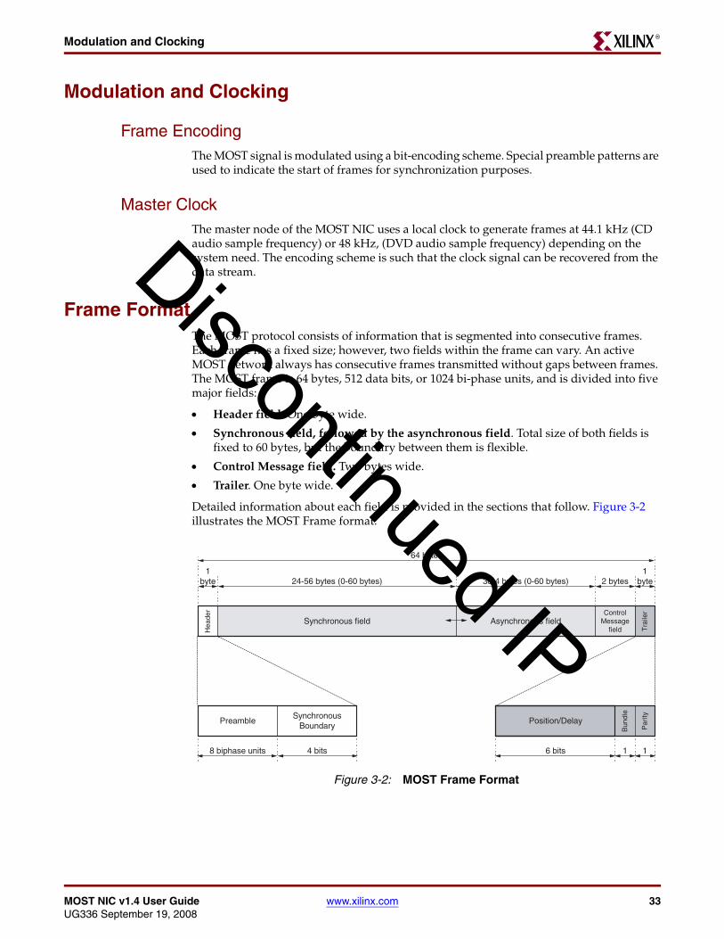
Frame EncodingThe MOST signal is modulated using a bit-encoding scheme. Special preamble patterns are used to indicate the start of frames for synchronization purposes.
Master ClockThe master node of the MOST NIC uses a local clock to generate frames at 44.1 kHz (CD audio sample frequency) or 48 kHz, (DVD audio sample frequency) depending on the system need. The encoding scheme is such that the clock signal can be recovered from the data stream.
Frame FormatThe MOST protocol consists of information that is segmented into consecutive frames. Each frame has a fixed size; however, two fields within the frame can vary. An active MOST network always has consecutive frames transmitted without gaps between frames. The MOST frame is 64 bytes, 512 data bits, or 1024 bi-phase units, and is divided into five major fields:
• Header field. One byte wide.
• Synchronous field, followed by the asynchronous field. Total size of both fields is fixed to 60 bytes, but the boundary between them is flexible.
• Control Message field. Two bytes wide.
• Trailer. One byte wide.
Detailed information about each field is provided in the sections that follow. Figure 3-2 illustrates the MOST Frame format.
Figure 3-2: MOST Frame Format
Synchronous fieldControl
Messagefield
Asynchronous field
Position/Delay
64 bytes
1byte2 bytes24-56 bytes (0-60 bytes) 36-4 bytes (0-60 bytes)
PreambleSynchronous
Boundary
8 biphase units 4 bits
Tra
iler
Hea
der
Par
ity
Bun
dle
6 bits 11
1byte
Discontinued IP

34 www.xilinx.com MOST NIC v1.4 User GuideUG336 September 19, 2008
Chapter 3: MOST Link Layer BackgroundR
Header FieldThe Header field is divided into two fields. The Preamble and Synchronous Boundary Descriptor (SBD) are each four bits wide. The Preamble is used for synchronization and the SBD is used to define where the synchronous field ends.
Preamble
The preamble field indicates the start of the frame and has three purposes:
• To create preamble patterns so that it is possible to synchronize with the MOST frame
• To use an encoding that makes it possible to synchronize to higher levels of state in ring: Block, which allows Control Channel transmission, and Super Block, which uses Control Channel bandwidth for status communication in the ring
• Distribute the wakeup event in the ring
The wakeup preamble event has no relation to the device wakeup described in the MOST specification. This preamble can be used to wake up the MOST NIC to a responsive state.
Synchronous Boundary Descriptor
The synchronous boundary descriptor field delineates where the synchronous field ends and the asynchronous field starts in the frame. The Synchronous Boundary value defines how many quadlets should be used for the synchronous field. Quadlets are groups of four consecutive bytes aligned to the start of the field. The asynchronous field starts where the synchronous field ends and their combined size is always 60 bytes.
Synchronous FieldThe Synchronous field size is a multiple of quadlets and can be in the range 4*N. The MOST Specification 2.4 only allows sizes where N is in the range [6..14]. The Xilinx MOST NIC core is a superset of the MOST specification and allows N to be in the range of [1..15]. The size is controlled by the Synchronous Boundary Descriptor.
Each byte is a separate timeslot for streaming data. Any number of these timeslots can be connected together into one single stream for the application. The grouping of channels is handled at application level. The MOST Specification 2.4 only allows one source of data per timeslot. The timeslot also needs to be allocated (owned) by that source.
Asynchronous FieldThe Asynchronous field size is a multiple of quadlets and can be in the range 4*N. The MOST Specification 2.4 only allows sizes where N is in the range [1..9]. The Xilinx MOST NIC core is a superset of the MOST specification and allows N to be in the range of [0..14]. The size is controlled by the Synchronous Boundary Descriptor.
The asynchronous field is used to transfer large data packets between nodes in the MOST ring network. A packet can be between 2 and 1014 bytes. The Asynchronous field implements an integrity check with a CRC mechanism; no handshaking or retransmission is implemented.
Control Message FieldThe Control Message channel utilizes the bandwidth in the Control Message field in the frame. All nodes in the MOST ring network use the Control Message channel to transfer
Discontinued IP

MOST NIC v1.4 User Guide www.xilinx.com 35UG336 September 19, 2008
Frame FormatR
messages. The Control Message channel implements arbitration, integrity check, and handshaking.
In addition, the Control Message channel is occasionally used to transmit network information around the ring. Sharing of this field is done using a static assignment within the frame protocol. The Control Message channel is available for control messages approximately 97% of the time.
TrailerThe Trailer of the frame is divided into three fields. First is the Position and Delay field, followed by the Bundle flag and the Parity bit. The Position and Delay field is used for position determination and synchronous data delay determination, while the Bundle flag is used together with the Asynchronous field only and the Parity is used for a simple Parity check of the frame.
Position and Delay
In 1022 frames within the Super Block (see Block and Super Block), this field represents the position of the node. In the remaining 2 frames, this field represents the synchronous delay of the node. Only after achieving lock to the Super Block is it possible to process this field correctly, and provide delay information to the application.
Position
When this field contains position information, it represents the position of the current node in the ring as described below.
Master node
The Master always sends 0 as the position value being the first MOST NIC in the ring network. When the master receives this field back from the ring, the stored value plus one is the Max Position value, which is available to the user through the MOST NIC host interface. The Max Position is also redistributed to the slaves.
Slave node
An active slave always increments this field by one. All active slaves or nodes in Bypass store the received position and make it available for the user through the MOST NIC host interface.
Delay
When this field contains delay information, it is represents the synchronous data delay in frames accumulated in the ring. Each MOST NIC activated as slave or master will transmit the delay value.
The delay value, combined with the max delay value, can be used to calculate any delay of synchronous data between any two nodes. In very large systems this can be useful information. For example, when two amplifiers are playing audio from the same synchronous channels, but are 100 samples apart from each other in the network.
Master Node
The master always sends 0 as the delay value. When the master receives this field back from the ring, the stored value plus one is the Maximum Delay value, which is available to
Discontinued IP

36 www.xilinx.com MOST NIC v1.4 User GuideUG336 September 19, 2008
Chapter 3: MOST Link Layer BackgroundR
the user through the MOST NIC host interface. The Maximum Delay is also redistributed to the slaves.
Slave Node
An active slave will increments this field by one if it is introducing a frame of delay of synchronous data (Synchronous Data Delay). If the slave is not introducing the delay it will forward the field as is. All active slaves or nodes in Bypass mode store the received delay and make it available for the user through the MOST NIC host interface.
Bundle
This bit is used to bundle together the asynchronous fields from a group of frames in order to create an asynchronous packet. Only the MOST NIC transmitting the packet modifies the Bundle flag. For more information, see “Asynchronous Channel,” page 40.
Parity
This bit is used for parity check of the frame and is calculated over the whole frame with the exception of the preamble and parity bit. Every active node recalculates this bit. In addition, every locked node (master, slave, or all bypass) also checks the parity and makes error information available to the user through the MOST NIC host interface.
Block and Super BlockA Block is comprised of 16 frames. To synchronize to the first frame in the Block, the normal Frame preamble is replaced by the Block preamble. Only the Control Message Channel needs alignment to Blocks. There is no other channels or fields in the frame with a relationship to Blocks.
A Super Block is comprised of 64 Blocks. The same method used to synchronize to Blocks is used for synchronization to Super Blocks except the first two block preambles are replaced with Super Block preambles.
Discontinued IP
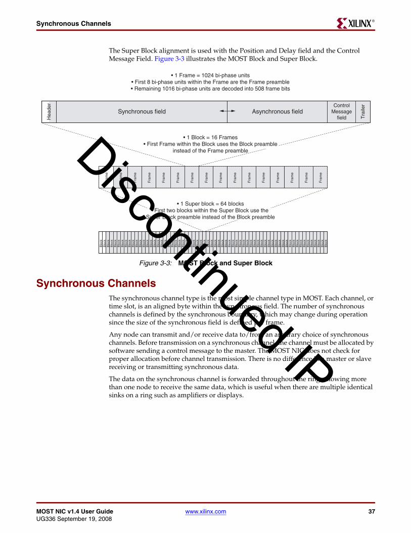
MOST NIC v1.4 User Guide www.xilinx.com 37UG336 September 19, 2008
Synchronous ChannelsR
The Super Block alignment is used with the Position and Delay field and the Control Message Field. Figure 3-3 illustrates the MOST Block and Super Block.
Synchronous ChannelsThe synchronous channel type is the most simple channel type in MOST. Each channel, or time slot, is an aligned byte within the synchronous field. The number of synchronous channels is defined by the synchronous boundary, which may change during operation since the size of the synchronous field is defined per frame.
Any node can transmit and/or receive data to/from an arbitrary choice of synchronous channels. Before transmission on a synchronous channel, the channel must be allocated by software sending a control message to the master. The MOST NIC does not check for proper allocation before channel transmission. There is no difference in a master or slave receiving or transmitting synchronous data.
The data on the synchronous channel is forwarded throughout the ring, allowing more than one node to receive the same data, which is useful when there are multiple identical sinks on a ring such as amplifiers or displays.
Figure 3-3: MOST Block and Super Block
Synchronous fieldControl
Messagefield
Asynchronous field
Tra
iler
Fra
me
Fra
me
Fra
me
Fra
me
Fra
me
Fra
me
Fra
me
Fra
me
Fra
me
Fra
me
Fra
me
Fra
me
Fra
me
Fra
me
Fra
me
Fra
me
Blo
ckB
lock
Blo
ckB
lock
Blo
ckB
lock
Blo
ckB
lock
Blo
ckB
lock
Blo
ckB
lock
Blo
ckB
lock
Blo
ckB
lock
Blo
ckB
lock
Blo
ckB
lock
Blo
ckB
lock
Blo
ckB
lock
Blo
ckB
lock
Blo
ckB
lock
Blo
ckB
lock
Blo
ckB
lock
Blo
ckB
lock
Blo
ckB
lock
Blo
ckB
lock
Blo
ckB
lock
Blo
ckB
lock
Blo
ckB
lock
Blo
ckB
lock
Blo
ckB
lock
Blo
ckB
lock
Blo
ckB
lock
Blo
ckB
lock
Blo
ckB
lock
Blo
ckB
lock
Blo
ckB
lock
Blo
ckB
lock
Blo
ckB
lock
Hea
der
• 1 Frame = 1024 bi-phase units• First 8 bi-phase units within the Frame are the Frame preamble• Remaining 1016 bi-phase units are decoded into 508 frame bits
• 1 Super block = 64 blocks• First two blocks within the Super Block use the
Super Block preamble instead of the Block preamble
• 1 Block = 16 Frames• First Frame within the Block uses the Block preamble
instead of the Frame preambleDiscontinued IP

38 www.xilinx.com MOST NIC v1.4 User GuideUG336 September 19, 2008
Chapter 3: MOST Link Layer BackgroundR
Application ExampleFigure 3-4 illustrates the general use of synchronous channels, including control message exchange and the use of the allocation mechanism. For detailed information about the example, see “Control Message Channel,” page 41.
The application example shows a simple network, constructed in the following way:
• A Head Unit with an Man-Machine Interface (MMI) (Master A), a CD player (Slave B), a radio tuner (Slave E), and two amplifiers (Slaves C and D).
• Before the message sequence occurs, the car has been started and the network initialized up to application level.
• Most messages in the message sequence are application messages.
• The application message protocol is implemented in software and transfers application information between the software in two separate nodes. Application messages are constructed using one or many normal control messages.
• Application messages in the message sequence are labeled AM, and in the sequence, the direction of the messages is shown as A > B, where A is the sending node and B is the receiving node.
Message Sequence One
The system starts playing a CD:
1. CD is selected by pushing a button on the MMI
Figure 3-4: Synchronous Application Example
Master A
MMI
Slave B
CD Player
Slave C
Amplifier 1
Slave D
Amplifier 2
Slave E
Tuner
Discontinued IP

MOST NIC v1.4 User Guide www.xilinx.com 39UG336 September 19, 2008
Synchronous ChannelsR
2. A > B AM: Allocate channels for the CD audio
3. B > A: An allocation control message request of 4 channels. The request is granted by the master node and channels 0, 5, 7, 8 are allocated.
4. B > A AM: Channels 0, 5, 7, 8 have been allocated for the CD audio
5. A > B AM: Connect source to the channels allocated for CD audio (start transmitting)
6. A > C AM: Connect sink to the CD audio channels 0,5,7,8 (start receiving)
7. A > D AM: Connect sink to the CD audio channels 0,5,7,8 (start receiving)
8. A > B AM: Play track 3 on the CD
9. Audio from track 3 is heard in both amplifiers
These sequences are specified in detail by the OEM for a specific system or infotainment platform, but there are also recommendations and specifications in the MOST specification.
In the sequence above, the initial data transmitted from the CD player is silence. Next, the amplifier is asked to connect when there is valid data (when the CD has started to transmit). In some systems, an amplifier gets or stays connected even when the source is known to transmit garbage, or not transmit at all, but in these cases the amplifier is informed via an application message to mute the output or ignore the data from the synchronous channels.
Message Sequence Two
Reusing the synchronous channels when switching from the playing a CD (from the previous sequence) to the tuner. While the CD has been playing, synchronous channels number 3 and number 4 have been deallocated by another function in the car.
1. Tuner is selected by pushing a button on the MMI
2. A > C AM: Disconnect from the CD audio channels (stop receiving)
3. A > D AM: Disconnect from the CD audio channels (stop receiving)
4. A > B AM: Disconnect from the CD audio channels (stop transmitting)
5. A > B AM: Deallocate the channels used for CD audio
6. B > A: A deallocate control message request using connection label 0. The request is granted by the master node and the channels are deallocated
7. B > A AM: The channels used for audio have been deallocated
8. A > E AM: Allocate channels to be used for radio tuner audio
9. E > A An allocation control message request of 4 channels. The request is granted by the master node and channels 0, 3, 4, 5 are allocated. channels
10. E > A AM: Channels 0, 3, 4, 5 are allocated for the radio tuner audio
11. A > E AM: Connect source to the channels allocated for radio tuner audio (start transmitting)
12. A > C AM: Connect sink to the radio tuner audio channels 0, 3, 4, 5 (start receiving)
13. A > D AM: Connect sink to the radio tuner audio channels 0, 3, 4, 5 (start receiving)
14. Audio from the radio tuner can be heard on both amplifiers.
Discontinued IP

40 www.xilinx.com MOST NIC v1.4 User GuideUG336 September 19, 2008
Chapter 3: MOST Link Layer BackgroundR
Asynchronous ChannelThe asynchronous packet channel can be used to send large amounts of data from one node to one or several nodes. A packet can be sent from any node in the network to any other node(s). The packet is variable in size and the data portion can be up to 1014 bytes long, where packet integrity is protected using CRC.
The asynchronous packet protocol is the same between master and slave. Neither the sending or the receiving node needs to know the type (master or slave) of the other node(s); an asynchronous packet sent to the master looks the same way for both sides as a packet sent from a slave to another slave or a packet sent from the master to a slave.
Packet FormatThe asynchronous packet is constructed from a header portion, a data portion, and a trailer portion. The header contains destination address, source address, and length, and the trailer is only a CRC.
Address Method
The asynchronous packet uses two types of addresses: logical address and alternate address. Both address types are 16 bits and use an exclusive range of values.
Logical Address
See Logical Address in the Control Channel section.
Alternate Address
The alternate address is set by the user through the MOST NIC host interface and can be any value in the range of 0x0000-0xFFFF. The alternate address can be used as both source address and destination address in the asynchronous packet header fields.
Destination Address
The destination address is the address to be used as destination. It can be a logical address or an alternate address.
Source Address
The source address is intended to be the logical address or the alternate address of the MOST NIC sending the packet.
Length
The length field defines the size of the data field in the asynchronous packet. The relationship between the size of the data field in bytes and the length value is outlined below:
Figure 3-5: Asynchronous Packet Format
Data2-1014 bytes
Destination Address2 bytes
Source Address2 bytes
Length1 byte
CRC2 bytes
Header (5 bytes) Data (2-1014 bytes) Trailer (2 bytes)
Discontinued IP
MOST NIC v1.4 User Guide www.xilinx.com 41UG336 September 19, 2008
Control Message ChannelR
Size in bytes = ( ( Length - 1 ) * 4 ) + 2
Example: If the length value is 5, the size of the data field would be
( 5 - 1 ) * 4 + 2 = 18 bytes
The range of the length value is 1 to 254, which provides possible data field sizes from 2 to 1014 bytes.
Data
The data portion of the asynchronous packet does not fill any other function in the link layer protocol, other than being the payload for the packet. The size of the data field is specified using the length field. All data is byte-oriented.
CRC
The content of the asynchronous packet is protected using CRC.
ArbitrationAs there is only one asynchronous field in the frame, nodes that want to send asynchronous data arbitrate for access to the asynchronous portion of the frame. The precise mechanism is beyond the scope of this document. However, the Xilinx MOST NIC will arbitrate when there is any asynchronous data to transmit.
Control Message ChannelThe Control Channel is available for a single control message per Block and each MOST NIC can arbitrate for the Control Channel at the start of every Block. The control channel implements a priority based and fair arbitration mechanism, an integrity check and handshaking. If no node is arbitrating, the control message channel will be unused in that Block.
Control messages are primarily used by the application through the Network Services software for signals at application and network administration level.
There are six types of messages. Only one message type is received by the MOST NIC user through the MOST NIC host interface. The other types are system control messages, which are processed by the MOST NIC. The MOST NIC responds automatically to these system control messages.
FormatThe Block contains 32 bytes of consolidated control message fields from 16 frames. Arbitration, message sending, and acknowledgement all occur within these 32 bytes.
Each control message consists of a five-byte header common for all six message types, and a message body of a different size depending on the message type specified in the header.
Discontinued IP

42 www.xilinx.com MOST NIC v1.4 User GuideUG336 September 19, 2008
Chapter 3: MOST Link Layer BackgroundR
The first part of the header is the destination address, followed by the source address and the message type.
Address Method
The control message uses four types of 16 bit addresses: position address, logical address, broadcast address, and groupcast address.
Position Address
Position address is based on the node position. Each MOST NIC has the address 0x0400 + Position. The range 0x0400-0x04FF is reserved for position addresses even though the maximum number of nodes in the same MOST ring network is 64.
The position address will be unique for all nodes in the MOST ring network and is only used as destination address in the control message header.
Logical Address
The logical address is set by the user through the MOST NIC host interface. The logical address can be any value in the range 0x0001-0x02FF or in the range 0x0500-0xFFFF. The default value is 0x0FFF.
The logical address is intended to be unique for all nodes in the MOST ring network and is always used as source address in the control message header.
Broadcast Address
The broadcast address is 0x03C8.
The broadcast address is only used as destination address in the control message header. When the broadcast address is used the control message is intended for all nodes in the MOST ring network, sending node excluded.
Groupcast Address
The groupcast address can be any value in the range 0x0300-0x03C7 or 0x03C9-0x03FF.
The groupcast address is only used as destination address in the control message header. When the groupcast address is used the control message is intended for all nodes with the that address in the MOST ring network, sending node excluded.
Destination Address
The destination address is the address to be used as destination. It can be a logical address, a position address, a groupcast address, or the broadcast address. The destination address is selected through the MOST NIC host interface.
Figure 3-6: Control Message Format
Header5 bytes
Message Body (Normal Message or Requests)3-19 bytes
Destination Address16 bits
Source Address16 bits
Message Type3 bits
Reserved5 bits
Discontinued IP

MOST NIC v1.4 User Guide www.xilinx.com 43UG336 September 19, 2008
Control Message ChannelR
Source Address
The source address is the logical address of the MOST NIC sending the control message. The source address is part of the header, even though it is only used by the receiving node(s) when using the normal message type.
Message Type
The message type is a 3-bit value that defines the type of message body to follow the control message header. The message type is selected through the MOST NIC host interface. There are six message types:
ArbitrationAs there is only one control field in the frame, nodes that want to send control data arbitrate for access to the control portion of the frame (the precise mechanism being beyond the scope of this document). However, the Xilinx MOST NIC arbitrates when there is any control data to transmit.
ChecksumAll control message types uses a full integrity protection using a checksum that is calculated over the complete message including the header.
Transmission StatusThe transmission status field is used to acknowledge (ACK) and not acknowledge (NAK) with error information. The transmission status value is used to determine if retransmission is needed. Depending on the message type the transmission status will be generated at different stages.
Format
The transmission status field is two bytes wide and split in half. Each half should contain identical information, and is one byte wide, containing two sub fields: ACK/NAK and Status. The ACK/NAK field contains the ACK flag and NAK flag, and the status field contains a status value that must be interpreted using the ACK/NAK field as shown in Figure 3-7.
Table 3-1: Control Message Type
Message Type Description
0x0 Normal Message
0x1 Remote Read Request
0x2 Remote Write Request
0x3 Allocation Request
0x4 Deallocation Request
0x5 Get Source Request
Discontinued IP
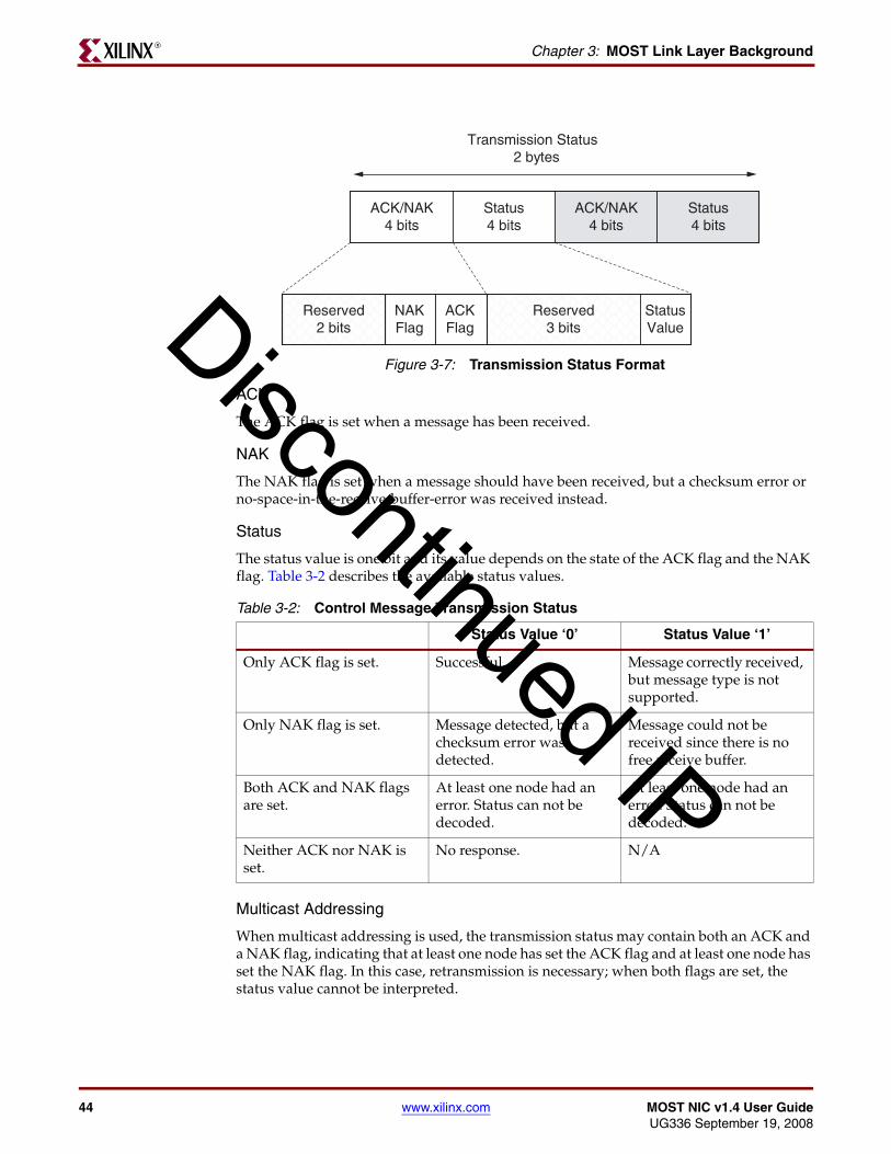
44 www.xilinx.com MOST NIC v1.4 User GuideUG336 September 19, 2008
Chapter 3: MOST Link Layer BackgroundR
ACK
The ACK flag is set when a message has been received.
NAK
The NAK flag is set when a message should have been received, but a checksum error or no-space-in-the-receive-buffer-error was received instead.
Status
The status value is one bit and its value depends on the state of the ACK flag and the NAK flag. Table 3-2 describes the available status values.
Multicast Addressing
When multicast addressing is used, the transmission status may contain both an ACK and a NAK flag, indicating that at least one node has set the ACK flag and at least one node has set the NAK flag. In this case, retransmission is necessary; when both flags are set, the status value cannot be interpreted.
Figure 3-7: Transmission Status Format
Table 3-2: Control Message Transmission Status
Status Value ‘0’ Status Value ‘1’
Only ACK flag is set. Successful. Message correctly received, but message type is not supported.
Only NAK flag is set. Message detected, but a checksum error was detected.
Message could not be received since there is no free receive buffer.
Both ACK and NAK flags are set.
At least one node had an error. Status can not be decoded.
At least one node had an error. Status can not be decoded.
Neither ACK nor NAK is set.
No response. N/A
ACK/NAK4 bits
Transmission Status2 bytes
Status4 bits
ACK/NAK4 bits
Status4 bits
ACKFlag
NAKFlag
Reserved2 bits
Reserved3 bits
StatusValueDiscontinued IP
MOST NIC v1.4 User Guide www.xilinx.com 45UG336 September 19, 2008
Control Message ChannelR
Retransmission
If the transmission status is other than successful (ACK='1' and Status='0'), the message will be retransmitted by the MOST NIC. A retransmission means that the MOST NIC needs to arbitrate for a new opportunity to send the complete message.
The host will configure two parameters in the MOST NIC that will control the behavior of the retransmissions. These parameters are the amount of retries and the back-off time between the retries.
The amount of retries will tell the MOST NIC how many times it can retransmit the same message when there are continuous failures. Once the MOST NIC has reach this many retransmission without success it will stop the retransmissions and let the host know the last transmission status value. The MOST NIC can be configured to do no retransmissions at all using this parameter.
The back-off time between retransmissions is specified in number of arbitration opportunities that are skipped. When there has been an unsuccessful transmission it is sometimes better to wait some time before trying to transmit again. By skipping arbitration opportunities it will be possible to create the back-off time for this purpose.
The ranges of the number of retransmissions and the back-off time parameters are described in the MOST NIC control register section.
Control Message TypesThere are six message types:
• Normal Control Message
• Allocation Message
• Deallocation Message
• Remote Read Message
• Remote Write Message
• Get Source Message
Each message type has its own format and transmission sequence. Detailed information about each message type is provided in the sections that follow. All reserved fields should be set to equal zero.
Normal Control MessageThe normal control message type is used when sending a message from software on one node to the software on another node.
This message type is the only message type that can be received using the MOST NIC host interface. The other message types will be received and handled by the MOST NIC internally.
The host software implements another protocol layer that is used on top of the normal messages. Messages sent and received using this software protocol layer are called Application Messages. At software application level only the Application Messages are seen and not the normal control messages.
For the normal control message type, the source address field in the header is often used by the receiving application to send new messages back to the sending application.
Discontinued IP

46 www.xilinx.com MOST NIC v1.4 User GuideUG336 September 19, 2008
Chapter 3: MOST Link Layer BackgroundR
Format
Figure 3-8 illustrates the normal message format.
Data
The data field of a normal control message can hold arbitrary information. The size of the data field is 17 bytes when using a singlecast address (not a groupcast address or the broadcast address). When using multicast addressing (a groupcast address or the broadcast address) the size of the data field is only 16 bytes to make room for the multicast counter field.
Multicast Counter
The multicast counter is used when sending groupcast or broadcast messages. The field will contain the value of a local counter, which resides in each node. At the completion of any transmission of a normal control message with multicast addressing the counter will increment by one in the sending node.
When receiving a retransmitted multicast message, the Xilinx MOST NIC core automatically discards messages it has already forwarded to the user.
Checksum
The checksum is calculated over the complete control message including the control message header.
Transmission Status
When a node has received a complete normal message, it will set the proper bits in transmission status value. The transmission status will then be received by the node sending the message.
Allocation MessageThe allocation message is used to allocate synchronous channels within the synchronous field. The master node has a resource mechanism built in the MOST NIC to handle allocation message requests. All nodes must send the allocation message requests to the master node. Typically, the address 0x0400 is used as destination address to ensure that it is sent to the correct node.
Figure 3-8: Normal Message Format
Normal Message19 bytes
Data16 or 17 bytes
Multicast Counter0 or 1 byte
Checksum2 bytesDiscontinued IP

MOST NIC v1.4 User Guide www.xilinx.com 47UG336 September 19, 2008
Control Message ChannelR
The number of synchronous channels that can be allocated per message is between one and eight depending on the need. If more channels need to be allocated, multiple allocation requests are required.
The MOST NIC that receives an allocation message request will generate the allocation response automatically without the need of intervention by the host software.
Request Format
Figure 3-9 illustrates the allocation request format.
Number of Channels
The number of channels field is used to specify the number of synchronous channels, from one to eight, that need to be allocated.
Response Format
Figure 3-10 illustrates the allocation response format.
Figure 3-9: Allocation Request Format
Reserved1 byte
Allocation Request3 bytes
Number of Channels1 byte
Reserved1 byte
Figure 3-10: Allocation Response Format
Allocation Response12 bytes
Status1 byte
Free Count1 byte
Channel List8 bytes
Checksum2 bytes
Discontinued IP

48 www.xilinx.com MOST NIC v1.4 User GuideUG336 September 19, 2008
Chapter 3: MOST Link Layer BackgroundR
Status
When generating the allocation response, the following status codes in Table 3-3 are used.
If the number of requested channels is greater than the number available, the allocation is denied, and if the Number of channels field in the request is out of range (illegal value) the Out of range status code is used (0x04).
Free Count
The free count field shows the number of available synchronous channels at the responding node after the allocation sequence completes.
Channel List
The channel list field contains the first 8 free synchronous channels in the responding nodes allocation table. If there are not enough available synchronous channels to fill out the complete field, the field content is padded with the value 0xFF.
The master node always tries to fill all 8 bytes in the list with free channels independently of the number requested in the Number of Channels field of the allocation request. If the allocation is successful, the first channel number in the channel list is also the connection label for the allocated group of channels.
Checksum
Checksum is calculated by the responding MOST NIC over the complete sequence including the header, request, and response.
Transmission Status
The transmission status is generated and transmitted by the MOST NIC sending the allocation request after the checksum verification has been made over the complete message. If there are errors in the transmission status, the allocation is canceled.
The MOST NIC sending the request only generates a transmission status if there was a response generated, which is determined by a non-zero response.
Deallocation MessageDeallocation messages are used to deallocate synchronous channels previously allocated using the allocation message type. As with the allocation message type, the deallocation request must be sent to the master node. The MOST NIC receiving a deallocation message
Table 3-3: Allocation Response Status
Status Description
0x01 Allocation granted
0x02 Resource mechanism is busy
0x03 Allocation denied
0x04 Out of range
0x05 Target is a slave device
0x00, 0x06-0xFF Reserved
Discontinued IP

MOST NIC v1.4 User Guide www.xilinx.com 49UG336 September 19, 2008
Control Message ChannelR
request generates the deallocation response automatically without intervention by the host software.
Request Format
Figure 3-11 illustrates the deallocation request format.
Connection label
The connection label field is used to specify the group of channels to be deallocated. The intention is to use the same connection label during the deallocation request as that provided by the allocation response, which is the first channel in an allocation sequence.
The range of the value for this field is [0x00..(4*(current SBD)-1)], 0x7F]. 0x7F as a connection label is a deallocate all request.
Response Format
Figure 3-12 illustrates the deallocation response format.
Figure 3-11: Deallocation Request Format
Deallocation Request3 bytes
Reserved1 byte
Connection Label1 byte
Reserved1 byte
Figure 3-12: Deallocation Response Format
Deallocation Response4 bytes
Checksum2 bytes
Reserved1 byte
Status1 byte
Discontinued IP

50 www.xilinx.com MOST NIC v1.4 User GuideUG336 September 19, 2008
Chapter 3: MOST Link Layer BackgroundR
Status
When generating the deallocation response, status 0x01, 0x04, or 0x05 are used. Table 3-4 describes the deallocation status codes.
If the connection label value is not within range, the Out of range value must be used (0x04). Because deallocation cannot be denied, the Deallocation granted status value (0x01) should be generated independently of the actual deallocation taking place.
Checksum
The checksum is calculated over the complete sequence including the header, request, and response.
Transmission Status
The transmission status is generated and transmitted by the MOST NIC sending the deallocation request after the checksum verification has been made over the complete message. If there are errors in the transmission status, the deallocation is canceled.
The MOST NIC sending the request only generates a transmission status if there was a response generated, which is determined by a non-zero response.
Remote Read MessageThe remote read message type, used only by network analysis tools, can be used to request a memory read from another MOST NIC. The MOST NIC that receives a remote read message request generates the remote read response automatically without intervention by the host software. The Xilinx MOST NIC always reports all zeroes to any remote read request.
Table 3-4: Deallocation Response Status
Status Description
0x01 Deallocation granted
0x02 Resource mechanism is busy
0x04 Out of range
0x05 Target is a slave device
0x00, 0x06-0xFF ReservedDiscontinued IP

MOST NIC v1.4 User Guide www.xilinx.com 51UG336 September 19, 2008
Control Message ChannelR
Request Format
Figure 3-13 illustrates the read request format.
Memory Address
The memory address field defines the memory location at the receiving node to begin reading data.
Response Format
Figure 3-14 illustrates the remote read response format.
Memory Data
The memory data field is the 8 following bytes of data starting at the memory address specified in the request.
Checksum
The checksum is calculated over the complete sequence including the header, request, and response.
Transmission Status
No transmission status is transmitted when using the remote read message type. However, the host software still needs to know the request status being sent by the MOST
Figure 3-13: Remote Read Request Format
Remote Read Request3 bytes
Reserved1 byte
Memory Address1 byte
Reserved1 byte
Figure 3-14: Remote Read Response Format
Remote Read Response10 bytes
Checksum2 bytes
Memory Data8 bytes
Discontinued IP

52 www.xilinx.com MOST NIC v1.4 User GuideUG336 September 19, 2008
Chapter 3: MOST Link Layer BackgroundR
NIC. The Xilinx MOST NIC core generates a transmission status anyway for use by the host software.
Remote Write MessageThe remote write message type, used only by network analysis tools, can be used to request a memory write from another MOST NIC.
The MOST NIC receiving a remote write message request generates the remote write response automatically, without intervention by the host software. The Xilinx MOST NIC does not support this message type, and returns Message Type Not Supported in the Transmission Status field.
Request Format
Memory Address
The memory address field contains the memory address of the receiving node where the write access shall start.
Number of Bytes
The number of bytes field defines how many bytes from the data field shall be written to memory. This value can be in the range 0 to 8.
Memory Data
This memory data field contains the data to be written into the memory of the receiving MOST NIC.
Checksum
The checksum is calculated over the complete request including the control message header.
Transmission Status
The transmission status (similar to the Normal Control message type) is generated by the MOST NIC receiving the request. If there is a checksum error the request is cancelled and no bytes are written to memory.
Figure 3-15: Remote Write Request Format
Remote Write Request13 bytes
Reserved1 byte
Memory Address1 byte
Number of Bytes1 byte
Memory Data8 bytes
Checksum2 bytes
Discontinued IP

MOST NIC v1.4 User Guide www.xilinx.com 53UG336 September 19, 2008
Control Message ChannelR
Get Source MessageThe Get Source message can be used to find which node is transmitting on specific synchronous channels. If a get source request is sent using a multicast address only the node that is transmitting on the synchronous channel mentioned in the request will reply. The node will reply with information about itself for identification, e.g. position in the ring and address. Typically, this message type is not used in networks nor in network analysis tools.
The MOST NIC that receives a Get Source Message request generates the get source response automatically, without the need of intervention by the host software.
Request Format
Figure 3-16 illustrates the get source request format.
Synchronous Channel
The synchronous channel field contains the synchronous channel number used in the query. If any of the addressed nodes is currently transmitting to this synchronous channel those nodes will respond to this request. If the value of the synchronous channel is 0xff, then any node that matches the destination address field will respond as if it was transmitting.
Following the MOST protocol, only one node should be transmitting on the same synchronous channel which should be the node that allocated the synchronous channel. However, it is still feasible for nodes to transmit on the same channel, thus overwriting the data transmitted by others. In such a case multiple nodes could respond to this message. No special handling is implemented in the MOST NIC to handle this. The response received at the requesting node will be what was sent from the closest responding node upstream of the requesting node, i.e. the last node to overwrite the response from the other node(s).
Figure 3-16: Get Source Request Format
Get Source Request3 bytes
Reserved1 byte
Synchronous Channel1 byte
Reserved1 byte
Discontinued IP

54 www.xilinx.com MOST NIC v1.4 User GuideUG336 September 19, 2008
Chapter 3: MOST Link Layer BackgroundR
Response Format
Figure 3-17 illustrates the get source request format.
Position
The position field contains the node position of the responding node.
Group Address
The group address field contains the lower byte of the groupcast address of the responding node.
Logical Address
The logical address field contains the logical address of the responding node.
Checksum
The checksum is calculated over the complete sequence including the header, request, and response.
Transmission Status
There is no transmission status transmitted when the Get Source message is used. However, the host needs to know the status of the request being sent by the MOST NIC. The Xilinx MOST NIC core generates a transmission status for use by the host software.
Source and Destination Addresses
Self Addressing
As a general rule, there is no requirement that a MOST NIC be able to transmit messages to itself. However, the master MOST NIC must be able to perform both allocations and deallocations. The Xilinx MOST NIC supports self-addressing of all message types, with the exception that it never receives multicast messages sent to a multicast address when it is the transmitting node.
Message Type and Multicast
All message types support singlecast addressing (logical or position address) as the destination address.
Figure 3-17: Get Source Response Format
Get Source Response5 bytes
Reserved3 bytes
Synchronous Channel1 byte
Reserved1 byteDiscontinued IP

MOST NIC v1.4 User Guide www.xilinx.com 55UG336 September 19, 2008
Control Message ChannelR
The use of multicast addressing (groupcast or broadcast address) depends on the message type. Table 3-5 describes both supported and unsupported message types for use with multicast addressing in the Xilinx MOST NIC.
Network InformationThe Control Message Channel also contains network information that is distributed once per Super Block. The master distributes connection labels in the allocation table, maximum position, and maximum delay to the slaves in the network. Slaves modify the channel active flags during the transmission depending on the transmit state of the corresponding synchronous channels in the slave node.
Application software in slave nodes occasionally makes use of the received network information. In some cases, the application software can use this information to see which synchronous channels are associated with a certain connection label. Because the network information is only transmitted once per Super Block, the slave must be certain the allocation of the channels takes place prior to reception. Application software in slave nodes also uses the maximum position and the maximum delay. As with the allocation information, the maximum position and maximum delay values are not fresh information because they are only distributed once per Super Block.
Table 3-5: Message Type Multicast Support
Message Type Multicast addressing
Normal Supported
Allocation Not supported
Deallocation Not supported
Remote Read Not supported
Remote Write Supported
Get Source Supported
Discontinued IP

56 www.xilinx.com MOST NIC v1.4 User GuideUG336 September 19, 2008
Chapter 3: MOST Link Layer BackgroundR
Format
Figure 3-18 illustrates the network information provided in the Super Block.
Synchronous Channel Resource Table
The Synchronous Channel Resource Table is 60 bytes, of which each byte is divided into into a connection label and an Active flag. The position in the table corresponds to the synchronous channel in the synchronous field. The table is sent in order of connection label.
When the synchronous field is fewer than 60 bytes wide, the Synchronous Channel Resource table is padded with 0x70, which indicates that the synchronous channel is not allocated.
Connection Label
The connection label value defines a group of channels, which has been allocated using a single allocation request. There is one connection label per synchronous channel.
Active Flag
The channel active flag indicates if a synchronous channel is used for transmission. When the master transmits the synchronous channel resource table, this bit is always cleared to '0.'
If a slave node is transmitting on a synchronous channel, it sets this bit to '1' for the corresponding position in the synchronous channel resource table. The criteria for setting this bit is the same as responding to a Get Source Request message. For the positions in the synchronous channel resource table where the slave node is not transmitting on the corresponding synchronous channels, this bit is forwarded like any other information in the control message field.
Maximum Position
The maximum position represents the number of nodes in the network; valid values are 1 to 64.
Figure 3-18: Network Information Format
60 bytes of allocation table
7 bits of connection label
(not allocated = 0x70)Active
32 bytes of control message channel within a Block
64 bytes of control message channel within first two Blocks in the Super Block
32 bytes of control message channel within a Block
Blo
ck
Blo
ck
Blo
ck
Blo
ck
Blo
ck
Blo
ck
Blo
ck
Blo
ck
Blo
ck
Blo
ck
Blo
ck
Blo
ck
Blo
ck
Blo
ck
Blo
ck
Blo
ck
Blo
ck
Blo
ck
Blo
ck
Blo
ck
Blo
ck
Blo
ck
Blo
ck
Blo
ck
Blo
ck
Blo
ck
Blo
ck
Blo
ck
Blo
ck
Blo
ck
Blo
ck
Blo
ck
Blo
ck
Blo
ck
Blo
ck
Blo
ck
Blo
ck
Blo
ck
Blo
ck
Blo
ck
Blo
ck
Blo
ck
Blo
ck
Blo
ck
Blo
ck
Blo
ck
Blo
ck
Blo
ck
Blo
ck
Blo
ck
Blo
ck
Blo
ck
Blo
ck
Blo
ck
Blo
ck
Blo
ck
Blo
ck
Blo
ck
Blo
ck
Blo
ck
Blo
ck
Blo
ck
Blo
ck
Blo
ck
4 bytesystemdata
Max
Delay
Max
PositionReserved Reserved
One byte entry in the allocation table
Discontinued IP

MOST NIC v1.4 User Guide www.xilinx.com 57UG336 September 19, 2008
Synchronous Channel Resource MechanismR
Maximum Delay
The maximum delay represents the number of nodes in the network using synchronous data delay.
Synchronous Channel Resource MechanismThe synchronous channel resource mechanism only resides in the master node. The master node allocates and deallocates the synchronous channels on remote or local requests. To allocate and deallocate synchronous channels, the Allocation and Deallocation message are used, respectively.
When allocating synchronous channels, the resource mechanism in the master always chooses the first available (free/not allocated) synchronous channels from the synchronous field. If there are fewer available channels than requested in the allocation message, the allocation is rejected, and if there was a checksum error in the allocation message, the allocation is cancelled.
Every successful allocation results in a group of channels being allocated and marked with the connection label in the synchronous channel resource table. The connection label is the same value as the position of the first synchronous channel in the synchronous field among the group of channels allocated. Synchronous channels are allocated in groups, of one to eight channels.
When deallocating messages, the connection label is used to tell which channel group should be deallocated. Consecutive allocations and deallocations of different sizes cause a fragmentation of the synchronous channel resource table. An allocation being made when the table is fragmented can cause the allocated group of channels to be spread out over the synchronous field.
After a change of the synchronous boundary, the synchronous channel resource mechanism in the MOST NIC is invalid and has to be reset by the reception of a deallocate all message.
The MOST specification specifies how synchronous channels are allocated by the node that will transmitting on the synchronous channels. This behavior is guaranteed by the application software; the MOST NIC does not care if the synchronous channels are allocated before use.
Startup and SynchronizationAny MOST NIC needs to synchronize to frame patterns generated by the master MOST NIC. After the MOST NIC is synchronized, synchronization is lost only if the preamble pattern does not match the expected value. Change of synchronous boundary does not cause loss of synchronization.
Lock and UnlockAfter the clock has been recovered by the MOST NIC, it synchronizes to Frames, Blocks, and Super Blocks.
Synchronize to Frames
To synchronize to frames, the Xilinx MOST NIC first matches one of the four preambles. The MOST NIC continuously monitors to make sure that one of the four preambles occurs
Discontinued IP

58 www.xilinx.com MOST NIC v1.4 User GuideUG336 September 19, 2008
Chapter 3: MOST Link Layer BackgroundR
at the right position. If the MOST NIC finds at least one other preamble (after the first one) at the correct position, it generates a lock event for the host.
If the Xilinx MOST NIC is already synchronized to frames and does not find any of the four preambles at the expected position, it generates an unlock event for the host and immediately tries to synchronize again.
When a MOST NIC is Frame synchronized, it handles these parts of the frame:
• Preamble checking
• Synchronous boundary detection
• Synchronous channels
• Asynchronous packet channel
• Position detection and increment
• Parity check and generation
Synchronize beyond Frames
To Block or Super Block synchronize, the MOST NIC must be synchronized to Frames and find the appropriate preamble.
• When a MOST NIC is Block synchronized, it handles all parts of the frame covered by frame synchronization, and additionally, makes available the Control Message Channel.
• When a MOST NIC is Super Block synchronized, it handles all parts of the frame covered by Block synchronization, and additionally, makes available network information and delay detection and increment.
• If a Xilinx LogiCORE MOST NIC is Block or Super Block synchronized, and no preamble is found in the correct condition, an unlock event is generated, and it immediately starts to synchronize again.
• If a Xilinx MOST NIC is Block or Super Block synchronized, it falls back to Frame synchronized if a Frame preamble replaces a Block or Super Block preamble.
• If a Xilinx MOST NIC is Super Block synchronized, it falls back to Block synchronized if a Block preamble replaces a Super Block preamble.
BypassA MOST NIC slave starts out in the bypass state, where the MOST signal is directly forwarded from the input to the output pin. During bypass, synchronization is active, and the MOST NIC attempts full synchronization.
Unlocked SlaveAn unlocked slave node that is not Frame synchronized attempts full synchronization while forwarding and retiming the MOST signal from the input to the output pin.
Unlocked MasterThe master generates the complete preamble sequence regardless of the synchronization state with respect to the received signal. If the master MOST NIC is not synchronized to the input it has no data to transfer to the next frame, so it fills out the frame with dummy data of all zeros.
Discontinued IP

MOST NIC v1.4 User Guide www.xilinx.com 59UG336 September 19, 2008
Startup and SynchronizationR
Device WakeupSlaves start out in bypass state with an idle ring. Eventually, the master node starts transmitting light, and all slave nodes forward this incoming signal, and transition to the bypass state.
Discontinued IP
60 www.xilinx.com MOST NIC v1.4 User GuideUG336 September 19, 2008
Chapter 3: MOST Link Layer BackgroundR
Discontinued IP
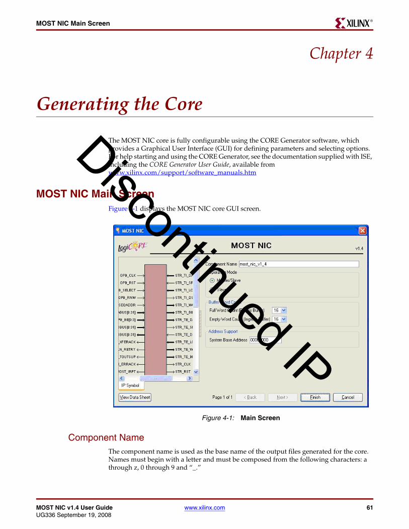
MOST NIC v1.4 User Guide www.xilinx.com 61UG336 September 19, 2008
MOST NIC Main ScreenR
Chapter 4
Generating the Core
The MOST NIC core is fully configurable using the CORE Generator software, which provides a Graphical User Interface (GUI) for defining parameters and selecting options. For help starting and using the CORE Generator, see the documentation supplied with ISE, including the CORE Generator User Guide, available from www.xilinx.com/support/software_manuals.htm
MOST NIC Main ScreenFigure 4-1 displays the MOST NIC core GUI screen.
Component NameThe component name is used as the base name of the output files generated for the core. Names must begin with a letter and must be composed from the following characters: a through z, 0 through 9 and “_.”
Figure 4-1: Main Screen
Discontinued IP

62 www.xilinx.com MOST NIC v1.4 User GuideUG336 September 19, 2008
Chapter 4: Generating the CoreR
Operating Mode
Select one of the following operating modes:
• Master/Slave: The MOST NIC is configured to operate as a master or slave on the MOST ring in regular operation. The master/slave configuration is further controlled through user-programmable control registers.
• Slave Only: The MOST NIC is configured to operate as a slave node on the MOST ring in regular operation.
Buffer Word Count Triggers
The MOST core supports 16 logical channel buffers for the receive and transmit directions for a total of 32 logical channel buffers. Each logical channel buffer can hold 32 words of data.
Ingress and egress are defined from the reference point of the core. An ingress transaction is synonymous with a write from the user interface. An egress transaction is synonymous with a read from the user interface. Table 4-1 summarizes the user interface access types, and identifies the buffer type, ingress or egress.
In each direction, eight logical channels are dedicated for OPB, four for streaming ingress (write) and four for streaming egress (read). All buffers can assert interrupts to an external microprocessor to indicate that the buffer requires processing; however, neither the ingress receive buffer nor the egress transmit buffers assert an interrupt on the OPB interface. The word count at which the interrupt is asserted is configurable as defined below. Word counts may be chosen separately for ingress buffers, and egress buffers. All ingress buffers use the same word counts. All egress buffers use the same word counts.
Full Word Count (Egress Buffer)
An interrupt is generated every time C_FWC number words have been filled in the egressbuffer. The number of words can be 8 or 16. The default value is 16.
Setting the C_FWC to 8 generates a buffer interrupt when eight words have been written to the buffer by the source. Another buffer interrupt is generated when an additional 8 words are written by the source, or a MOST interrupt when an end-of- packet is received for asynchronous data.
Empty Word Count (Ingress Buffer)
An interrupt is generated when there are at least C_EWC number of unused word locations in the ingress buffer. The number of words can be 8 or 16. The default value is 16.
Table 4-1: Ingress / Egress Buffer Mapping
Access Buffer Type Word Count
RX OPB Read Egress Full word count
RX Streaming Read Egress Full word count
RX Streaming Write Ingress Empty word count
TX OPB Write Ingress Empty word count
TX Streaming Read Egress Full word count
TX Streaming Write Ingress Empty word count
Discontinued IP

MOST NIC v1.4 User Guide www.xilinx.com 63UG336 September 19, 2008
Output GenerationR
Setting the C_EWC to 8 generates a buffer interrupt when there is room for at least 8 words to be written to the ingress buffer. When the interrupt is asserted, there is an assumption that the external processor will write 8 words to the ingress buffer. In essence, 8 locations of the buffer are now reserved and no longer considered unused. When there are 8 more unused word locations, an additional buffer interrupt is generated.
OPB Address SupportThe MOST NIC controller is an OPB slave. The address of the MOST NIC controller can beconfigured through the CORE Generator GUI.
Output GenerationThe output files generated by the CORE Generator are placed in the project directory. See the MOST NIC Getting Started Guide for a complete description of the CORE Generator output files. A summary of the output files includes
• The netlist file for the core
• Source code for the low-level drivers for the core
• Supporting CORE Generator files
• Release notes and documentation
• Subdirectories containing an HDL example design
• Scripts to run the core through the back-end tools and to simulate the core using the Mentor ModelSim® simulator
Table 4-2: Word Count Parameters
NamePossible Values
Default Description
C_FWC 8, 16 16 Full Word Count. The received word count at which an interrupt is generated.
C_EWC 16, 8 16 Empty Word Count. The available transmit word count at which an interrupt is generated.
Table 4-3: MOST NIC Controller Design Parameter
Name Possible Values Default Description
C_BASEADDR Valid address range: 0x00000000 - 0xffffc000, where bits 18-31 must be 0b
0x00000000 Base Address for the core
Discontinued IP

64 www.xilinx.com MOST NIC v1.4 User GuideUG336 September 19, 2008
Chapter 4: Generating the CoreR
Discontinued IP

MOST NIC v1.4 User Guide www.xilinx.com 65UG336 September 19, 2008
Required ConstraintsR
Chapter 5
Constraining the Core
This chapter defines the MOST NIC core constraints, implemented in the example designUCF delivered with the core. Portions of the UCF are copied into the descriptions below toprovide examples, and should be studied in conjunction with the HDL source code for theexample design.
Required Constraints
Device, Package, and Speedgrade SelectionThe MOST NIC core can be implemented in the following devices using the followingspeed grades, provided they are large enough to accommodate the core:
• Virtex-II Pro, -5
• Virtex-4, -10
• Spartan-3/XA, -4
• Spartan-3E/XA, -4
• Spartan-3A, -4
• Spartan-3A DSP, -4
I/O Location ConstraintsNo specific I/O location constraints are required.
Placement ConstraintsNo specific placement constraints are required.
Timing ConstraintsThe core can have up to two clock domains:
• OPB_Clk for the main system clock for the core
• MOST_COM_CLK and MOST_PLL_CLK for the MAC transmitter and receiver
These clock nets and the signals within the core that cross these clock domains must beconstrained appropriately in a UCF.
Discontinued IP

66 www.xilinx.com MOST NIC v1.4 User GuideUG336 September 19, 2008
Chapter 5: Constraining the CoreR
PERIOD Constraints for Clock Nets
OPB_Clk
The clock provided to OPB_Clk must be constrained to the appropriate frequency. Thefrequency allowed will vary across devices, but will be at least 75 MHz for allimplementations. In addition, OPB_Clk must be at least 7/10 of the frequency ofMOST_PLL_CLK.
The following UCF syntax shows the necessary constraints being applied to the OPB_Clk signal for a 50 MHz clock:
# Set the Reference clock period constraints:NET "OPB_Clk" TNM_NET = "OPB_Clk";TIMEGRP "OPB_clock" = "OPB_Clk";TIMESPEC "TS_OPB_clock" = PERIOD "OPB_clock" 20000 ps HIGH 50 %;
MOST_COM_CLK and MOST_PLL_CLK
The clock provided to MOST_*_CLK must be constrained to the desired managementinterface operating frequency, where the two clocks are frequency locked to one another.In addition, there are requirements set on the two clocks depending on the mode of thecore that are fully depicted in the clock wrapper file provided in the example design. For afull master/slave core, there is a BUFGMUX in order to select the correct source for thereceived data. For a slave-only core, the two clocks are connected together.
Note: For normal slave operation, the clock should be tied to the recovery clock. For slave operation in loopback mode, the clock should be tied to the crystal clock. In order to switch between normal and loopback modes, the master/slave circuit can be used to change these sources while in operation.
The following UCF syntax shows a 45.158 MHz (CD audio rate) period constraint beingapplied to the MOST_PLL_CLK:
# Set the crystal clock period constraints:NET "MOST_PLL_CLK" TNM_NET = "MOST_PLL_CLK";TIMEGRP "MOST_PLL_CLOCK" = "MOST_PLL_CLK";TIMESPEC "TS_MOST_PLL_CLOCK" = PERIOD "MOST_PLL_CLOCK" 22144.274 ps HIGH 50 %;
Timespecs for Critical Logic within the Core
No specific timespecs for critical logic within the core required.
Discontinued IP

MOST NIC v1.4 User Guide www.xilinx.com 67UG336 September 19, 2008
SummaryR
Chapter 6
Configuration Space
This chapter describes the MOST NIC programming and status registers.
SummaryTable 6-1 defines the MOST Controller registers, all of which are 32-bits wide and represented in big endian format, where bit 0 is the MSB on left, and bit 31 is the LSB on the right, that is, 0:31.
Reserved BitsReads to reserved bits or unused bits return zero(s). Writes to read-only registers are ignored. Reads from write-only registers return zero(s).
Byte Enable SupportByte enable support is provided to the locations indicated in Table 6-1. Locations that do not support byte enables ignore the OPB_BE[0:3] signals and provide 32-bit writes and reads. Locations that do support byte enables qualify writes with the assertion of OPB_BE[0:3]. Read access ignores the OPB_BE[0:3] signal and provides 32-bit read data.
Table 6-1: Xilinx MOST Controller Register
Register Name AddressSize
(Words)Access
Byte Enable
Support
Reserved for Future Use
Reserved C_BASEADDR + 0x0000 -
C_BASEADDR + 0x00FC
64 Read only N
MOST Controller Registers
Version Register (VR) C_BASEADDR + 0x0100 1 Read only N
Soft Reset Register (SRR) C_BASEADDR + 0x0104 1 Read/write Y
Mode Select Register (MSR) C_BASEADDR + 0x0108 1 Read/write Y
Status Register (SR) C_BASEADDR + 0x010C 1 Read only N
Channel Control Register (CCR) C_BASEADDR + 0x0110 1 Read/write Y
Maximum and Current Position and Delay Register (MCPDR)
C_BASEADDR + 0x0114 1 Read only N
Discontinued IP

68 www.xilinx.com MOST NIC v1.4 User GuideUG336 September 19, 2008
Chapter 6: Configuration SpaceR
Logical Address Register (LAR) C_BASEADDR + 0x0118 1 Read/write Y
Alternate Address Register (AAR)
C_BASEADDR + 0x011C 1 Read/write Y
Group Address Register (GAR) C_BASEADDR + 0x0120 1 Read/write Y
Flush Control Register (FCR) C_BASEADDR + 0x0124 1 Write only Y
TX Buffer Error Register (TXBER)
C_BASEADDR + 0x0128 1 Read only N
RX Buffer Error Register (RXBER)
C_BASEADDR + 0x012C 1 Read only N
MOST Control Processing
Message Retry Count and Delay Register (MRCDR)
C_BASEADDR + 0x0130 1 Read/write Y
Control TX Status (CTXS) C_BASEADDR + 0x0134 1 Read/write Y
Control RX Status (CRXS) C_BASEADDR + 0x0138 1 Read only N
Control TX FIFO (CTXFIFO) C_BASEADDR + 0x013C 1 Write only N
Control TX Response FIFO (CTXRESFIFO)
C_BASEADDR + 0x0140 1 Read only N
Control RX FIFO (CRXFIFO) C_BASEADDR + 0x0144 1 Read only N
Reserved C_BASEADDR + 0x0148 2 Read only N
Interrupt Status / Control
MOST Interrupt Status Register (MISR)
C_BASEADDR + 0x0150 1 Read/write Y
MOST Interrupt Pending Register (MIPR)
C_BASEADDR + 0x0154 1 Read only N
MOST Interrupt Enable Register (MIER)
C_BASEADDR + 0x0158 1 Read/write Y
MOST Interrupt Clear Register (MICR)
C_BASEADDR + 0x015C 1 Write only Y
Buffer Interrupt Status Register (BISR)
C_BASEADDR + 0x0160 1 Read/write Y
Buffer Interrupt Pending Register (BIPR)
C_BASEADDR + 0x0164 1 Read only N
Buffer Interrupt Enable Register (BIER)
C_BASEADDR + 0x0168 1 Read/write Y
Buffer Interrupt Clear Register (BICR)
C_BASEADDR + 0x016C 1 Write only Y
Reserved C_BASEADDR + 0x0170 36 Read only N
Table 6-1: Xilinx MOST Controller Register (Continued)
Register Name AddressSize
(Words)Access
Byte Enable
Support
Discontinued IP

MOST NIC v1.4 User Guide www.xilinx.com 69UG336 September 19, 2008
SummaryR
Routing Table
Common Routing Table (CRT) C_BASEADDR + 0x0200 32 Read/write N
Logical Channel Enable (LCE) C_BASEADDR + 0x0280 1 Read/write Y
Reserved C_BASEADDR + 0x0284 7 Read only N
Slave Active Register 1 (SAR1) C_BASEADDR + 0x02A0 1 Read only N
Slave Active Register 2 (SAR2) C_BASEADDR + 0x02A4 1 Read only N
Reserved C_BASEADDR + 0x02A8 2 Read only N
Master Allocation Table (MAT) C_BASEADDR + 0x02C0 16 Read only N
Streaming Port MMR
Streaming Port MMR (SMMR) C_BASEADDR + 0x0300 64 Read/write Y
MOST PLL Control Registers
PLL Reference Count Register
(PRCR)
C_BASEADDR + 0x0400 1 Read/write Y
External PLL Reset Count
(EPRC)
C_BASEADDR + 0x0404 1 Read only N
Reserved
Reserved C_BASEADDR + 0x0408 766 Read only N
Transmit / Receive Buffer
Transmit Buffer (TXBUFF) C_BASEADDR + 0x1000 1024 Write only N
Receive Buffer (RXBUFF) C_BASEADDR + 0x2000 1024 Read only N
Reserved
Reserved C_BASEADDR + 0x3000 -
C_BASEADDR + 0x3FFC
1024 Read only N
Table 6-1: Xilinx MOST Controller Register (Continued)
Register Name AddressSize
(Words)Access
Byte Enable
Support
Discontinued IP
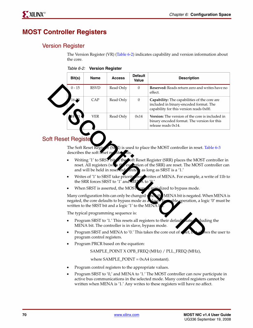
70 www.xilinx.com MOST NIC v1.4 User GuideUG336 September 19, 2008
Chapter 6: Configuration SpaceR
MOST Controller Registers
Version RegisterThe Version Register (VR) (Table 6-2) indicates capability and version information about the core.
Soft Reset RegisterThe Soft Reset Register (SRR) is used to place the MOST controller in reset. Table 6-3 describes the soft reset register bits.
• Writing ’1’ to SRST bit of the Soft Reset Register (SRR) places the MOST controller in reset. All registers (with the exception of the SRR) are reset. The MOST controller can and will be held in reset indefinitely as long as SRST is a ‘1.’
• Writes of ’1’ to SRST take priority over writes of MENA. For example, a write of 11b to the SRR forces SRST to ’1’ and MENA to ’0.’
• When SRST is asserted, the MOST core is initialized to bypass mode.
Many configuration bits can only be changed when the MENA bit is negated. When MENA is negated, the core defaults to bypass mode as a slave. To enable operation, a logic ’0’ must be written to the SRST bit and a logic ’1’ to the MENA bit.
The typical programming sequence is:
• Program SRST to ’1.’ This resets all registers to their default state, including the MENA bit. The controller is in slave, bypass mode.
• Program SRST and MENA to ’0.’ This takes the core out of reset, but allows the user to program control registers.
• Program PRCR based on the equation:
SAMPLE_POINT X OPB_FREQ (MHz) / PLL_FREQ (MHz),
where SAMPLE_POINT = 0xA4 (constant).
• Program control registers to the appropriate values.
• Program SRST to ’0,’ and MENA to ’1.’ The MOST controller can now participate in active bus communications in the selected mode. Many control registers cannot be written when MENA is ’1.’ Any writes to these registers will have no affect.
Table 6-2: Version Register
Bit(s) Name AccessDefault Value
Description
0 - 15 RSVD Read Only 0 Reserved: Reads return zero and writes have no effect.
16-23 CAP Read Only 0 Capability: The capabilities of the core are included in binary-encoded format. The capability for this version reads 0x00.
24 -31 VER Read Only 0x14 Version: The version of the core is included in binary encoded format. The version for this release reads 0x14.
Discontinued IP

MOST NIC v1.4 User Guide www.xilinx.com 71UG336 September 19, 2008
MOST Controller RegistersR
• MENA can be deasserted at any point, but this also forces the MOST controller into a bypass mode. In addition all buffers are flushed, and all logical channels disabled.
Table 6-3: Soft Reset Register
Bit(s) Name AccessDefault Value
Description
0 - 29 RSVD Read/Write 0 Reserved: Reads return zero and writes have no effect.
30 MENA Read/Write 0 MOST Enable: The MOST controller is enabled when this bit is asserted. When negated operational and configuration modes may be set.
The MOST controller will be operational when MENA is ‘1.’ When set to ‘0,’ the MOST controller is forced to the bypass mode as a slave and the controller is disabled
This bit is reset to ’0’ on assertion of SRST.
31 SRST Read/Write 0 Soft Reset: The MOST controller is reset if this bit is set to ’1.’ When asserted, all MOST controller registers, (except the SRST) are reset. When negated, operation of the MOST controller resumes - subject to the status of MENA
Discontinued IP

72 www.xilinx.com MOST NIC v1.4 User GuideUG336 September 19, 2008
Chapter 6: Configuration SpaceR
Mode Select RegisterThe Mode Select Register (MSR) configures the operating mode of the controller. This register can be read back to determine that it has been programmed correctly. However, to determine the actual state of the core, the Status Register (SR) must be read. Table 6-4 describes the mode select register bits.
• The MNSLV, RBDT, BYPASS, and LBACK bits can only be written when the MENA bit in the SRR is negated. When MENA bit is asserted, the MSR register is sampled, and the appropriate mode is enabled.
• Master/Slave operation is configured via the MNSLV bit.
• The RBDT, BYPASS and LBACK bits are mutually exclusive. Only one of these bits may be set at a time. Normal mode is enabled when RBDT, BYPASS, and LBACK are all ‘0’. If more than one bit is set, BYPASS takes priority, and then LBACK.
• A node configured as a master node (MNSLV = 1) cannot be put into BYPASS mode. To place the core into BYPASS, the core will need to configured to be a slave node (MNSLV = 0)
• When MENA is changed from a ’1’ to a ’0’ the RBDT, BYPASS, and LBACK bits are initialized to the default states (BYPASS mode)
• In Normal mode, the MOST controller participates in normal network operation.
• The default state of the MOST controller is BYPASS mode as a slave.
Table 6-4: Mode Select Register
Bit(s) Name AccessDefault Value
Description
0 - 17 RSVD Read Only 0 Reserved: Reads return zero and writes have no effect.
18 EBYPASS Read/Write 1 External bypass: The value in this bit is forwarded to the MOST_EXT_BYPASS pin in order to drive a bypass state to external circuitry, such as a PLL. This bit is not related to the BYPASS mode of the core (bit 30 of this register).
19 TCTL Read/Write 0 Transmit control synchronization override: Allows transmission of normal control messages for a master when the ring is not stable.
1 = enables transmission of normal messages even when node is not block synchronized
0 = regular operation
This bit can only be written when MENA in the SRR is negated. This bit can only be asserted when MNSLV is also asserted.
20 ENRST Read/Write 1 External not-reset: The value in this bit is forwarded to the MOST_EXT_NRESET pin in order to drive a reset to external circuitry, such as a PLL.
21- 24 RSVD Read Only 0 Reserved: Reads return zero and writes have no effect.
Discontinued IP

MOST NIC v1.4 User Guide www.xilinx.com 73UG336 September 19, 2008
MOST Controller RegistersR
25 DAZ Read/Write 0 Drive all Zeros: Forces the transmit pin to be 1’b0.
1 = drive all Zero’s on the tx pin.
0 = drive normal data
26 STRON Read/Write 0 Stream On: Indicates if there is an external module attached to the streaming port
1 = external module is attached to the streaming port.
0 = external module is not attached to the streaming port
If an external module is not attached to the streaming port, then all MMR access to the streaming port will be terminated by the MOST controller directly.
This bit can only be written when MENA in the SRR is negated
27 MNSLV Read/Write 0 Master - Not Slave: This bit selects the master or slave functionality. Writes to this bit position have no effect if the operating mode is Slave Only unless RBDT is also asserted.
1 = set the controller to Master mode
0 = set the controller to Slave mode
This bit can only be written when MENA in the SRR is negated
28 RBDT Read/Write 0 Ring Break Diagnosis Test Mode Selection: RBD test mode select bit.
1 = enables the core for an RBD test mode.
0 = does not enable the core for an RBD test mode
This bit can only be written when MENA in the SRR is negated.When MNSLV is also asserted in a slave-only core, this will force the core into a pseudo-master mode, which will provide valid traffic on the MOST_TX line. For all other programming, this bit will have no effect on the operation of the core.
Table 6-4: Mode Select Register (Continued)
Bit(s) Name AccessDefault Value
Description
Discontinued IP

74 www.xilinx.com MOST NIC v1.4 User GuideUG336 September 19, 2008
Chapter 6: Configuration SpaceR
Transmit control synchronization override
Control messages may only be sent or received when the node is at least Block synchronized. For a Master node, this does not happen until all nodes on the rings are also synchronized. However, a Master node initiates the preamble generation for the ring. If this mode is set, the synchronization state of the present Master node will be ignored, and the node may transmit the request portion of a normal control message.
Note: Even with this setting active, all transmissions are guaranteed to fail, since an acknowledgement for the message will never be received.
Ring Break Diagnosis Test Mode
The Ring Break Diagnosis (RBD) mode lets the user diagnose a fatal error in the network which prevents the propagation of light through the network. Four conditions cause a fatal error:
1. The device has an insufficient or no distribution voltage.
2. An optical receiver is defective.
3. An optical transmitter is defective.
4. The optical connection between the transmitter and the receiver is interrupted.
Bypass Mode
In Bypass mode, the signal received at the input (MOST_RX) port is forwarded to the output (MOST_TX) port. As long as the node is in BYPASS mode, it is transparent to the network (that is, the position count is not incremented) and this node does not transmit any frames. However, the node receives any frame, stores the position and delay value, and performs parity checking. Bypass mode is also set when MENA=0.
29 LBACK Read/Write 0 Loopback Selection: The Loopback mode select bit.
1 = enable Loopback mode
0 = disable Loopback mode
This bit can only be written when MENA in the SRR is negated
30 BYPASS Read/Write 1 Bypass mode Selection: The Bypass mode select bit.
1 = enable Bypass Mode
0 = disable Bypass Mode.
This bit can only be written when MENA in the SRR is negated and the core is configured as a Slave (MNSLV = 0)
Bypass mode is also forced active when MENA is reset to’0’
31 RSVD Read Only 0 Reserved: Reads return zero and writes have no effect.
Table 6-4: Mode Select Register (Continued)
Bit(s) Name AccessDefault Value
Description
Discontinued IP

MOST NIC v1.4 User Guide www.xilinx.com 75UG336 September 19, 2008
MOST Controller RegistersR
Loopback Mode
In Loopback mode, the MOST controller transmits a frame onto the MOST bus. Any transmitted frame is looped back internally to the core to the RX line and is acknowledged if it is a control message. It does not participate in normal bus communication and does not receive any frames transmitted by other MOST nodes.
Normal Mode
In Normal mode, the MOST controller participates in bus communication by transmitting and receiving frames. The Drive All Zeros (DAZ) control bit overrides the output of the TX pin in any operational mode. When this bit is set, the TX output is forced to ‘0’.
Status Register (SR)The Status Register (Table 6-5) shows the current status of the MOST controller.
Table 6-5: Status Register
Bit(s) Name AccessDefault Value
Description
0 - 17 RSVD Read Only 0 Reserved: Reads return zero and writes have no effect.
18 EBYPASS Read Only 1 External bypass: The current value of the MOST_EXT_BYPASS pin.
19 TCTL Read Only 0 Transmit control synchronization override: Indicates that transmission of normal control messages enabled for any synchronization state
1 = transmission of normal messages is enabled even when node is not block synchronized
0 = regular operation
20 ENRST Read Only 1 External not-reset: The current value of the MOST_EXT_NRESET pin.
21 DAZ Read Only 0 Drive all zeros: Indicates the DAZ bit is set
1 = DAZ is set, and as such the TX output has been forced to ‘0’.
0 = The DAZ bit is not set
22 SBLCK Read Only 0 Super Block Lock: Indicates synchronization to the super block
1 = controller is phase and frequency locked to the bit stream and synchronized to the super block
0 = controller is not synchronized to super block
23 BLCK Read Only 0 Block Lock: Indicates synchronization to the block
1 = controller is phase and frequency locked to the bit stream and synchronized to the block
0 = the controller is not synchronized to block
Discontinued IP

76 www.xilinx.com MOST NIC v1.4 User GuideUG336 September 19, 2008
Chapter 6: Configuration SpaceR
Channel Control Register The Channel Control Register (CCR) (Table 6-6) configures information for the synchronous, asynchronous, and control channels.
• The SBD bits control the portion of the MOST frame dedicated to synchronous and asynchronous data. This value determines the boundary between the synchronous and asynchronous data area in the frame.
For example, a value of 10 indicates that there are 10 quadlets (10*4 bytes) of synchronous data and 5 quadlets (5*4 bytes) of asynchronous data in the frame.
24 FLCK Read Only 0 Frame Lock: Indicates synchronization to the frame
1 = controller is phase and frequency locked to the bit stream and synchronized to the frame
0 = controller is not phase and frequency locked to the bit stream and not synchronized to the frame
25 FOS Read Only 0 Fibre Optic Status: Indicates the signal being received on the MOST_FOR_STATUS pin.
26 STRON Read Only 0 Stream On: Indicates if there is an external module attached to the streaming port
1 = external module is attached to the streaming port.
0 = external module is not attached to the streaming port
27 MNSLV Read Only 1 Master/Not slave: Indicates that the MOST controller is master or slave
1 = MOST controller is configured as a master
0 = MOST controller is configured as a slave
28 RBDT Read Only 0 Ring Break Diagnosis Test: Indicates that the MOST controller is in RBD test mode
1 = in RBD test mode
0 = not in RBD test mode
29 LBACK Read Only 0 Loopback: Indicates that the MOST controller is in Loopback mode
1 = in Loopback mode
0 = not in Loopback mode
30 BYPASS Read Only 1 Bypass: Indicates that the MOST controller is in Bypass mode
1 = in Bypass mode
0 = not in Bypass mode
31 RSVD Read Only 0 Reserved: Reads return zero and writes have no effect.
Table 6-5: Status Register (Continued)
Bit(s) Name AccessDefault Value
Description
Discontinued IP

MOST NIC v1.4 User Guide www.xilinx.com 77UG336 September 19, 2008
MOST Controller RegistersR
• The SBD value may change at any time during operation. However, after a change of the synchronous boundary, the synchronous channel resource mechanism becomes invalid and has to be reset by the reception of a deallocate all message.
• The minimum legal value for SBD is 1 (0x1). Writes of 0 are treated as a write of 1.
• The SBD bits can only be written when this node is programmed as a master. The value read from the register will always be the active SBD state in the ring. If this node is not enabled, the value read will always be the default value. If this node is acting as a master, this will be the value previously programmed. If this node is acting as a slave, it will be the SBD received from the ring.
Maximum and Current Position and Delay RegisterThe Maximum and Current Position and Delay Register (MCPDR) (Table 6-7) provides the maximum number of devices (position) and the maximum delay value of the MOST network. For a slave node, this maximum position and delay are derived from the Network Information Channel on the MOST ring; as a result, this register takes some time to stabilize at initialization and after every unlock event. It also provides the current position and delay value of the device.
Table 6-6: Channel Control Register
Bit(s) Name AccessDefault Value
Description
0 - 27 RSVD Read/Write 0 Reserved: Reads to return zero and writes have no effect.
28 - 31 SBD Read/Write 6 Synchronous Boundary Descriptor: Reads indicates the boundary between the synchronous and asynchronous data areas in the frame.
The SBD bits can only be written when this node is configured as a master as set by MNSLV in MSR. When the core is enabled as a Master, this will automatically take effect
Table 6-7: Maximum and Current Position and Delay Register
Bit(s) Name AccessDefault Value
Description
0 RSVD Read Only 0 Reserved: Reads return zero and writes have no effect.
1 - 7 MAXDELAY Read Only 0 Maximum Delay Value: Indicates the total number of node/frame delays for synchronous data within the MOST network.
8 RSVD Read Only 0 Reserved: Reads return zero and writes have no effect.
9- 15 MAXPSTN Read Only 0 Maximum Position Value: Indicates the total number of active nodes within the MOST network.
16 RSVD Read Only 0 Reserved: Reads return zero and writes have no effect.
Discontinued IP

78 www.xilinx.com MOST NIC v1.4 User GuideUG336 September 19, 2008
Chapter 6: Configuration SpaceR
Logical Address Register This Logical Address Register (LAR) (Table 6-8) indicates the logical address of this node, which is used by all nodes to address a single node, and is unique even if there are multiple devices of the same type. The logical address is always used as source address in the control message header, but can also be used as destination address in the asynchronous packet header. Valid ranges are 0x0001-0x02FF and 0x0500-0xFFFF. No checking of a valid LAR is performed in hardware. Users must ensure this register is programmed with a valid value.
Alternate Address RegisterThe Alternate Address Register (AAR) (Table 6-9) indicates the alternate address of this node, and is used by all nodes to address a single node. This address is unique, even if there are multiple devices of same type. The alternate address is set by the user and can be given any value in the range 0x0000–0xFFFF. The alternate address can be used as both source address and destination address in the asynchronous packet header fields.
17 - 23 NODEDELAY Read Only 0 Node Delay Value: Indicates the number of node delay from the timing master downstream to this node, for synchronous data. This value will be 0 in case of timing master.
24 RSVD Read Only 0 Reserved: Reads return zero and writes have no effect.
25 - 31 NODEPSTN Read Only 0 Node Position: Indicates the physical position of the node in the MOST network. All the active slave nodes will increment this value by 1. This value will be 0 in case of timing master.
Table 6-7: Maximum and Current Position and Delay Register (Continued)
Bit(s) Name AccessDefault Value
Description
Table 6-8: Logical Address Register Description
Bit(s) Name AccessDefault Value
Description
0 - 15 RSVD Read/Write 0 Reserved: Reads return zero and writes have no effect.
16 - 31 LAR Read/Write 0x0FFF Logical Address: Configures the logical address of the node in the MOST ring
Table 6-9: Alternate Address Register
Bit(s) Name AccessDefault Value
Description
0 - 15 RSVD Read/Write 0 Reserved: Reads return zero and writes have no effect.
16 - 31 AAR Read/Write 0x0000 Alternate Address: Configures the alternate address of the node in the MOST ring.
Discontinued IP

MOST NIC v1.4 User Guide www.xilinx.com 79UG336 September 19, 2008
MOST Controller RegistersR
Group Address Register The Group Address Register (GAR) (Table 6-10) indicates the group address of this node, and provides access to a group of devices. The group address can be set by the application, and is typically used to control several devices of same type (for example, active speakers).
The grouping of devices must be established during definition/initialization of the system. Groups can be dynamically built by modifying the group address. The group address can be any value in the range 0x0300–0x03C7 or 0x03C9–0x03FF. The default address (0x03C8) is reserved for multicast; the user should change the GAR from this default value.
Note: The high byte of GAR may not be modified by the user, because all group addresses must start with 0x03.
Flush Control RegisterThe Flush Control Register (FCR) (Table 6-11) register allows the Synchronous, Asynchronous, and Control Buffers to be flushed.
Table 6-10: Group Address Register
Bit(s) Name AccessDefault Value
Description
0 - 15 RSVD Read/Write 0 Reserved: Reads return zero and writes have no effect.
16 - 23 GAR (high) Read Only 0x03 Group Address High Byte: Configures the group address of the node in the MOST ring- hard coded to group address range of 0x03
24 - 31 GAR (low) Read/Write 0xC8 Group Address Low Byte: Configures the group address of the node in the MOST ring, and can be set to any value.
Table 6-11: Flush Control Register Description
Bit(s) Name AccessDefault Value
Description
0 - 23 RSVD Write Only 0 Reserved: Reads return zero and writes have no effect.
24-27 FCHN Write Only 0 Flush Channel: Configures the logical channel to be flushed.
28 FDIR Write Only 0 Flush Direction.
1 = Flush the transmit buffer
0 = Flush the receive buffer
Discontinued IP

80 www.xilinx.com MOST NIC v1.4 User GuideUG336 September 19, 2008
Chapter 6: Configuration SpaceR
Transmit Buffer Error Register The Transmit Buffer Error Register (TXBER) indicates the transmit logical channel buffers with underflow or overflow errors. Tables 6-12 and 6-13 summarize and describe the register bits.
• TXBER bits are cleared when the appropriate buffer has been flushed via the FCR. The bits are set on subsequent underflow or overflow conditions.
• When an error condition sets any of the TXBER bits, the TXBUFERR bit is set in the MOST interrupt status register, if enabled.
29 RSVD Write Only 0 Reserved: Reads return zero and writes have no effect.
30 FLCB Write Only 0 Flush Logical Channel Buffer: Enables a logical channel buffer to be flushed
1 = Flush the logical channel buffer as indicated by FDIR and FCHN.
0 = Do not flush a logical channel buffer
31 FCTB Write Only 0 Flush Control Buffer: Enables a control buffer to be flushed
1 = Flush the control buffer as indicated by FDIR
0 = Do not flush a control buffer
This bit only needs to be written once with a ’1’ to flush the appropriate buffer. The bit will automatically return to ‘0’
Table 6-11: Flush Control Register Description (Continued)
Bit(s) Name AccessDefault Value
Description
Table 6-12: Transmit Buffer Error Register Bits
0 1 2 3 4 5 6 7
TXOLC15 TXOLC14 TXOLC13 TXOLC12 TXOLC11 TXOLC10 TXOLC9 TXOLC8
8 9 10 11 12 13 14 15
TXOLC7 TXOLC6 TXOLC5 TXOLC4 TXOLC3 TXOLC2 TXOLC1 TXOLC0
16 17 18 19 20 21 22 23
TXULC15 TXULC14 TXULC13 TXULC12 TXULC11 TXULC10 TXULC9 TXULC8
24 25 26 27 28 29 30 31
TXULC7 TXULC6 TXULC5 TXULC4 TXULC3 TXULC2 TXULC1 TXULC0
Discontinued IP

MOST NIC v1.4 User Guide www.xilinx.com 81UG336 September 19, 2008
MOST Controller RegistersR
Receive Buffer Error RegisterThe Receive Buffer Error Register (RXBER) indicates which receive logical channel buffers have underflow or overflow errors. Tables 6-14 and 6-15 summarize and describe the register bits.
• RXBER bits are cleared when the appropriate buffer has been flushed (via the FCR). The bits are set on subsequent underflow or overflow conditions.
• When an error condition sets any of the RXBER bits, the RXBUFERR bit is set in the MOST interrupt status register, if enabled.
Table 6-13: Transmit Buffer Error Register
Bit(s) Name AccessDefault Value
Description
0 - 15 TXOLC_N_ Read Only
0 Transmit Overflow Logical Channel: Indicates a logic channel has overflowed.
1 = The indicated (_N_) logical channel has overflowed
0 = The indicated (_N_) logical channel has not overflowed.
16 - 31 TXULC_N_ Read Only
0 Transmit Underflow Logical Channel: Indicates a logic channel has underflowed.
1 = The indicated (_N_) logical channel has underflowed
0 = The indicated (_N_) logical channel has not underflowed.
Table 6-14: Receive Buffer Error Register Bits
0 1 2 3 4 5 6 7
RXOLC15 RXOLC14 RXOLC13 RXOLC12 RXOLC11 RXOLC10 RXOLC9 RXOLC8
8 9 10 11 12 13 14 15
RXOLC7 RXOLC6 RXOLC5 RXOLC4 RXOLC3 RXOLC2 RXOLC1 RXOLC0
16 17 18 19 20 21 22 23
RXULC15 RXULC14 RXULC13 RXULC12 RXULC11 RXULC10 RXULC9 RXULC8
24 25 26 27 28 29 30 31
RXULC7 RXULC6 RXULC5 RXULC4 RXULC3 RXULC2 RXULC1 RXULC0
Discontinued IP

82 www.xilinx.com MOST NIC v1.4 User GuideUG336 September 19, 2008
Chapter 6: Configuration SpaceR
MOST Control Processing
Message Retry Count and Delay Register The Message Retry Count and Delay Register (MRCDR) ((Table 6-16) contains the retry count and delay value for the re-transmission of the control messages. The count value configures how many times the re-transmission should take place and the delay value configures the gap between the re-transmission. This register should not be changed during the transmission of a control message, as the changes may not propagate to the active message.
Table 6-15: Receive Buffer Error Bit Description
Bit(s) Name AccessDefault Value
Description
0 - 15 RXOLC_N_ Read Only 0 Receive Overflow Logical Channel: Indicates a logic channel has overflowed.
1 = The indicated (_N_) logical channel has overflowed
0 = The indicated (_N_) logical channel has not overflowed
16 - 31 RXULC_N_ Read Only 0 Receive Underflow Logical Channel: Indicates a logic channel has underflowed.
1 = The indicated (_N_) logical channel has underflowed
0 = The indicated (_N_) logical channel has not underflowed
Table 6-16: Message Retry Count and Delay Register Description
Bit(s) Name AccessDefault Value
Description
0 - 15 RSVD Read/Write 0 Reserved: Reads return zero and writes have no effect.
16 - 23 DLYVALUE Read/Write 1 Delay Value: Configures the gap between the re-transmission of control messages. The time unit is always measured as blocks within the control channel. Valid values are 0x00 to 0xFF.
24 - 31 RTRYCNT Read/Write 1 Retry Count: Configures the number of re-transmission. Valid values are 0x00 to 0xFF.
Discontinued IP

MOST NIC v1.4 User Guide www.xilinx.com 83UG336 September 19, 2008
MOST Control ProcessingR
Control Transmit Status RegisterThe Control Transmit Status (CTXS) register (Table 6-17) contains status and control for the transmission of control messages.
Control Receive Status Register The Control Receive Status (CRXS) register (Table 6-18) contains status and control for the transmission of control messages.
Table 6-17: Control Transmit Status Register Bit Description
Bit(s) Name AccessDefault Value
Description
0 - 29 RSVD Read/Write 0 Reserved: Reads return zero and writes have no effect.
30 CTXOCC Read 0 Transmit Occupancy: Indicates the number of control messages currently queued for transmission in the CTXFIFO. (The Control module can also queue 1 message in progress) Users should not add any control message if this register indicates ‘1.’
31 CNEWTX Write 0 New Transmit Message: Write a ‘1’ to indicate that a new transmit message has been added to the transmit control message buffer. Reads always return’0.’
Table 6-18: Control Receive Status Register Bit Description
Bit(s) Name AccessDefault Value
Description
0 - 29 RSVD Read Only 0 Reserved: Reads return zero and writes have no effect.
30 CRXOCC Read Only 0 Receive Occupancy: Indicates if there is any control message currently queued for reception. Users should not try to read a control message if this register indicates ‘0’
31 CNEWRX Read Only 0 New Receive Message: Indicate that a new receive message was received since the last read to this register. This bit is cleared on reads. It is set when a receive message is successfully received from the MOST ring and added to the CRXFIFO
Discontinued IP

84 www.xilinx.com MOST NIC v1.4 User GuideUG336 September 19, 2008
Chapter 6: Configuration SpaceR
Control Transmit FIFO The Control Transmit FIFO (CTXFIFO) register (Table 6-19) is a write buffer used to add control messages for transmission.
Control messages can be two to six words in length. The control transmit message FIFO contains sufficient storage to hold one complete message. The control module within the core will also queue a message, for a total storage capacity for 2 messages. The FIFO is accessed by writing words sequentially to the CTXFIFO, where all reserved bits must be written with zeroes. The order in which words of the message must be added are as follows:
Control Transmit Message Structure
The first write contains the destination and source addresses. Destination Address (DSTA) is the destination of the control message. Source Address (SRCA) is the source of the message–which should be set to the current logical address of the core.
The second write contains the message priority, type, and the first three bytes of the message. The bytes are added to the Control Transmit FIFO in network order.
The Message Type (MSGT) is a 3-bit binary encoded message type. The user can write any type of control message to the CTXFIFO. Bytes 0-N are written with control fields or data as necessary. The remaining fields in the second word contain the first three bytes of the message, as indicated in Table 6-21.
The third to sixth write contains the remaining bytes of the message. Only as many bytes as are required need to be written to the CTXFIFO.
Table 6-19: Control Transmit FIFO Bit Description
Bit(s) Name AccessDefault Value
Description
0 - 31 TXMSG Write Only Not
initialized
Transmit Message: Transmit messages are added to the control transmit message FIFO by writing to this registers
Table 6-20: Control TX MSG: First Word
0 - 15 16-31
DSTA SRCA
Table 6-21: Control TX MSG: Second Word
0 1 - 4 5 - 7 8 - 15 16- 23 24 - 31
RSVD PRIOR MSGT Byte0 Byte1 Byte2
Table 6-22: Control TX MSG: Third through Sixth Word
0 - 7 8 - 15 16- 23 24 - 31
ByteN ByteN+1 ByteN+2 ByteN+3
Discontinued IP

MOST NIC v1.4 User Guide www.xilinx.com 85UG336 September 19, 2008
MOST Control ProcessingR
Control Message Encoding and Response
Any type of control message can be sent from user software using CTXFIFO. Responses to transmitted messages are returned in the CTXRESFIFO. Any messages which receive a NAK in the transmission field or are otherwise errored are automatically retried by hardware, subject to the retry values in the MRCDR registers.
The CTLTXFAIL interrupt is asserted if the counters expire and the message was not successfully transmitted. Table 6-23 describes the message type encoding and response of both the CTLTKOK interrupt and the returned receive message.
Table 6-23: Message Type Encoding and Actions
MSGTMessage
TypeCTLTXOKAssertion
CTLTXFAILAssertion
Response
3’b000 Normal On successful ACK received from the destination.
ACK not received and message retried as dictated by MRCDR
The original message and transmission status are returned in the CTXRESFIFO
3’b001 Remote Read Request
On successful reception of the read response
Response not received and message retried as dictated by MRCDR
The remote read response is returned as a received control message in the CTXRESFIFO. The message in the CTXRESFIFO includes the original request, response, and transmissions status.
3’b010 Remote Write Request
On successful ACK received from the destination
ACK not received and message retried as dictated by MRCDR
The original message and transmission status are returned in the CTXRESFIFO
3’b011 Allocation Request
On the successful reception of an allocation response, and successful transmission of the ACK from this node.
Response not received and message retried as dictated by MRCDR
The allocation response is returned as a received control message in the CTXRESFIFO. The message in the CTXRESFIFO will include the original request, response as well as the transmission status.
Discontinued IP

86 www.xilinx.com MOST NIC v1.4 User GuideUG336 September 19, 2008
Chapter 6: Configuration SpaceR
Note: Non-legal encodings are not checked by hardware, likely resulting in a corrupted MOST ring.
Control Transmit Response FIFO The Control Transmit Response FIFO (CTXRESFIFO) register (Table 6-24) is a read buffer used to read transmit message responses and status.
Control messages can be from two to six words in length. A seventh word is used to return the transmission status. The control transmit response FIFO contains sufficient storage to hold one complete message, response, and status. The buffer is accessed by reading words sequentially from the CTXRESFIFO.
This FIFO contains response messages received from destination nodes as a result of a transmitted control message from this node. The received message includes the original request, the response containing both the message answer (as well as checksum), and transmission status indicating transmission success or failure. Responses are received for allocation, deallocation, remote read, and get source control messages.
All seven words must be read for each message, even if the message contains fewer than seven words, and the seventh word always contains the transmission status. The order in which words of the message must be read is defined in Tables 6-25 through 6-28.
3’b100 Deallocation Request
On the successful reception of a deallocation response, and successful transmission of the ACK from this node.
Response not received and message retried as dictated by MRCDR
The deallocation response is returned as a received control message in the CTXRESFIFO. The message in the CTXRESFIFO will include the original request, the response as well as the transmission status.
3’b101 Get Source Request
On successful ACK on ring.
ACK not received and message retried as dictated by MRCDR
The Get Source Response is returned as a received control message in the CTXRESFIFO. The message in the CTXRESFIFO will include the original request, response and transmission status
3’b110,
3’b111
Reserved - do not use
n/a n/a n/a
Table 6-23: Message Type Encoding and Actions (Continued)
MSGTMessage
TypeCTLTXOKAssertion
CTLTXFAILAssertion
Response
Table 6-24: Control Transmit Response FIFO Bit Description
Bit(s) Name AccessDefault Value
Description
0 - 31 CTXRES Read Only
Not
initialized
Transmit Message Response: The original transmit message, response, and status is read via this register.
Discontinued IP
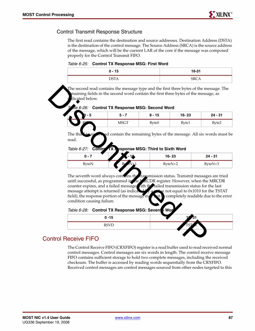
MOST NIC v1.4 User Guide www.xilinx.com 87UG336 September 19, 2008
MOST Control ProcessingR
Control Transmit Response Structure
The first read contains the destination and source addresses. Destination Address (DSTA) is the destination of the control message. The Source Address (SRCA) is the source address of the message, which will be the current LAR of the core if the message was composed properly for the Control Transmit FIFO.
The second read contains the message type and the first three bytes of the message. The remaining fields in the second word contain the first three bytes of the message, as indicated below.
The third to sixth read contain the remaining bytes of the message. All six words must beread.
The seventh word always contains the transmission status. Transmit messages are tried until successful, as programmed in the MRCDR register. However, when the MRCDR counter expires, and a failed message with the failed transmission status for the last message attempt is returned (as indicated by a value not equal to 0x1010 for the TSTAT field), the response portion of the message may not be completely readable due to the error condition causing failure.
Control Receive FIFOThe Control Receive FIFO (CRXFIFO) register is a read buffer used to read received normal control messages. Control messages are six words in length. The control receive message FIFO contains sufficient storage to hold two complete messages, including the received checksum. The buffer is accessed by reading words sequentially from the CRXFIFO. Received control messages are control messages sourced from other nodes targeted to this
Table 6-25: Control TX Response MSG: First Word
0 - 15 16-31
DSTA SRCA
Table 6-26: Control TX Response MSG: Second Word
0 - 5 5 - 7 8 - 15 16- 23 24 - 31
RSVD MSGT Byte0 Byte1 Byte2
Table 6-27: Control TX Response MSG: Third to Sixth Word
0 - 7 8 - 15 16- 23 24 - 31
ByteN ByteN+1 ByteN+2 ByteN+3
Table 6-28: Control TX Response MSG: Seventh Word
0 -15 16- 31
RSVD TSTAT
Discontinued IP
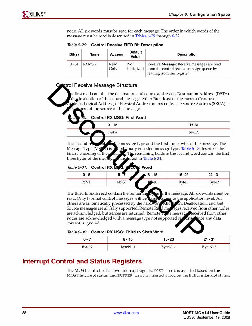
88 www.xilinx.com MOST NIC v1.4 User GuideUG336 September 19, 2008
Chapter 6: Configuration SpaceR
node. All six words must be read for each message. The order in which words of the message must be read is described in Tables 6-29 through 6-32.
Control Receive Message Structure
The first read contains the destination and source addresses. Destination Address (DSTA) is the destination of the control message–either Broadcast or the current Groupcast Address, Logical Address, or Physical Address of this node. The Source Address (SRCA) is the address of the source of the message.
The second read contains the message type and the first three bytes of the message. The Message Type (MSGT) is a 3-bit binary encoded message type. Table 6-23 describes the binary encoding of the messages. The remaining fields in the second word contain the first three bytes of the message as indicated in Table 6-31.
The third to sixth read contain the remaining bytes of the message. All six words must be read. Only Normal control messages will be passed along to the application level. All others are automatically processed by the hardware. Allocation, Deallocation, and Get Source messages are all fully supported. Remote Read messages received from other nodes are acknowledged, but zeroes are returned. Remote Write messages received from other nodes are acknowledged with a message type not supported response since any data content is ignored.
Interrupt Control and Status RegistersThe MOST controller has two interrupt signals: MOST_irpt is asserted based on the MOST Interrupt status, and BUFFER_irpt is asserted based on the Buffer interrupt status.
Table 6-29: Control Receive FIFO Bit Description
Bit(s) Name AccessDefault Value
Description
0 - 31 RXMSG Read Only
Not initialized
Receive Message: Receive messages are read from the control receive message queue by reading from this register
Table 6-30: Control RX MSG: First Word
0 - 15 16-31
DSTA SRCA
Table 6-31: Control RX MSG: Second Word
0 - 5 5 - 7 8 - 15 16- 23 24 - 31
RSVD MSGT Byte0 Byte1 Byte2
Table 6-32: Control RX MSG: Third to Sixth Word
0 - 7 8 - 15 16- 23 24 - 31
ByteN ByteN+1 ByteN+2 ByteN+3
Discontinued IP

MOST NIC v1.4 User Guide www.xilinx.com 89UG336 September 19, 2008
Interrupt Control and Status RegistersR
MOST Interrupt Control and Status RegistersMOST interrupts are controlled using four registers:
• Status (MISR): Indicates the interrupt status bits. These bits are set and cleared regardless of the status of the corresponding bit in the Interrupt Enable Register (MIER).
• Pending (MIPR): Indicates the interrupts that are actually indicated to software. In effect, bit wise it is the MISR register ANDed with the MIER register.
• Enable (MIER): Determines if an interrupt is generated or not.
• Clear (MICR): Clears the status bits in the MISR and MIPR register when a ’1’ is written to the corresponding bit in the Interrupt Clear Register (MICR).
Triggering MOST Interrupts
Two conditions cause the MOST Interrupt signal to assert:
• If a bit in the MISR is ’1’ and the corresponding bit in the MIER is ’1’
• Changing an MIER bit from ’0’ to ’1’ when the corresponding bit in the MISR is already ’1’
An interrupt is generated and the Pending Register bit (MIPR) is set if the corresponding mask bit in the Enable Register (MIER) is set.
Clearing MOST Interrupts
Two conditions cause the MOST Interrupt signal to deassert:
• Clearing a bit with a value of ‘1’ in the MISR/MIPR (by writing a ’1’ to the corresponding bit in the MICR)
• Changing an MIER bit from ’1’ to ’0,’when the corresponding bit in the MISR is ’1’
When deassertion and assertion conditions occur simultaneously, the MOST line is deasserted first, and then reasserted if the assertion condition remains true.
Common Bit Map
As the Status, Pending, Enable, and Clear registers have common mapping between registers, only a single mapping is depicted. Each has a unique register and address map, as indicated in Table 6-1. Each bit has a suffix:
• Status: INT
• Pending: PEN
• Enable: ENA
• Clear: CLR
Discontinued IP

90 www.xilinx.com MOST NIC v1.4 User GuideUG336 September 19, 2008
Chapter 6: Configuration SpaceR
Table 6-33: MOST Interrupt Register Bit Positions
0 1 2 3 4 5 6 7
RSVD RSVD RSVD RSVD RSVD STRINT RXBUFERR TXBUFERR
8 9 10 11 12 13 14 15
RXASYNEOP TXASYNEOP CTLRXNAK CTLRXNEW CTLTXFREE CTLTXFAIL CTLTXOK CTLARBLST
16 17 18 19 20 21 22 23
ARXCRCERR RSVD PERR BPCV MDLYCHG MPOSCHG DLYCHG POSCHG
24 25 26 27 28 29 30 31
RSVD LONCHG SBDCHG SYNCCHG RSVD RWP RSVD RSVD
Table 6-34: MOST Interrupt Register
Bit(s) Name Description
0 - 4 RSVD Reserved: Reads return zero and writes have no effect.
5 STRINT Streaming Interrupt: Indicates assertion of the streaming port interrupt signal strm_irpt
6 RXBUFERR RX Buffer Error: Indicates that a receive buffer has encountered an underflow or overflow error. The RXBER contains each LC buffer status.
7 TXBUFERR TX Buffer Error: Indicates that a transmit buffer has encountered an underflow of overflow error. The TXBER contains each LC buffer status.
8 RXASYNEOP RX ASYNC End of Packet: Indicates the RX asynchronous channel has received the end of the packet.
9 TXASYNEOP TX ASYNC End of Packet: Indicates the TX asynchronous channel has transmitted the end of packet
10 CTLRXNAK Control Message Not Acknowledged: Indicates a receive message could not be ACKed because the Control Message Receive FIFO was full.
11 CTLRXNEW Control Message Reception New: Indicates a new receive control message has been received into the Control Message Receive FIFO
12 CTLTXFREE Control Message Transmission Free: Indicates that a control message has just been de-queued from the Control Message Transmit FIFO. A user can now add another transmit control message.
13 CTLTXFAIL Control Message Transmission Failed: Indicates that the control message transmission failed (expired retry).(from the user Transmit Control Message FIFO)
14 CTLTXOK Control Message Transmission Completed: Indicates that a control message transmission successfully completed - Ack received. (from the user Transmit Control Message FIFO)
Discontinued IP

MOST NIC v1.4 User Guide www.xilinx.com 91UG336 September 19, 2008
Interrupt Control and Status RegistersR
MOST Interrupt Status Register
The MOST Interrupt Status Register (MISR) contains bits that are set when a specific interrupt condition occurs. If the corresponding mask bit in the MOST Interrupt Enable Register (MIER) is set, an interrupt is generated.
Interrupt bits in the MISR can be cleared by writing to the Interrupt Clear Register (MICR) or by directly writing the appropriate bit with ’0.’ For all bits in the MISR, a set condition takes priority over the clear condition, and the bit remains ‘1’.
The MISR is a read/write register and bits can be directly set and cleared under user control for diagnostic purposes. All bits are initialized to ’0’ on the assertion of reset.
MOST Interrupt Pending Register
The MOST Interrupt Pending Register (MIPR) indicates the interrupts that are actually indicated to software. In effect, it is the MISR register bit wise ANDed with the MIER. The
15 CTLARBLST Control Message Arb Lost: Indicates that arbitration to transmit a new control message was lost.
16 ACRCRXERR Async Receive CRC Error: Indicates that a CRC error occurred during the reception of a an asynchronous message. (note that the message is still received)
17 RSVD Reserved: Reads return zero and writes have no effect.
18 PERR Parity Error : Indicates that a parity error occurred during reception.
19 BPCV Bi-phase Coding Violation Occurred: Indicates that a coding violation has occurred during reception (outside of a preamble).
20 MDLYCHG Max Delay Change: Indicates a change in maximum delay has occurred.
21 MPOSCHG Max Position Change: Indicates a change in the maximum position has occurred
22 DLYCHG Delay Change: Indicates a change in delay has occurred
23 POSCHG Position Change: Indicates a change in position has occurred.
24 RSVD Reserved: Reads return zero and writes have no effect.
25 LONCHG LON Change: Indicates a change in the LON has occurred.
26 SBDCHG SBD Change: Indicates a change in the SBD has occurred.
27 SYNCCHG SYNC Change: Indicates a change in the frame, block or super block sync has occurred. The Status Register (SR) indicates the synchronization level obtained.
28 RSVD Reserved: Reads return zero and writes have no effect.
29 RWP Received Wake-up Preamble: Indicates that the MOST controller has received a wake-up preamble.
30-31 RSVD Reserved: Reads return zero and writes have no effect.
Table 6-34: MOST Interrupt Register (Continued)
Bit(s) Name Description
Discontinued IP

92 www.xilinx.com MOST NIC v1.4 User GuideUG336 September 19, 2008
Chapter 6: Configuration SpaceR
MIPR is a read-only register; writes have no effect. All bits are initialized to ’0’ on the assertion of reset.
MOST Interrupt Enable Register
The MOST Interrupt Enable Register (MIER) is used to enable or disable the generation of the interrupts. Interrupts are enabled by setting the appropriate bit in the MIER. MIER is a read/write register. All bits are initialized to ’0’ on the assertion of reset.
MOST Interrupt Clear Register
The MOST Interrupt Clear Register (MICR) is used to clear interrupt status bits. Writes of ’1’ clear the appropriate bit in the MOST Interrupt Status Register (MISR) and correspondingly, the MIPR.
This is a write-1-to-clear register. Users must write a ’1’ to the appropriate bit position to clear the indicated interrupt. Reads return ’0’ in each bit position. All bits are initialized to ’0’ on the assertion of reset.
Buffer Interrupt Control and Status RegistersBuffer interrupts are controlled through four registers:
• Status (BISR): Indicates the interrupt status bits, which are set and cleared regardless of the status of the corresponding bit in the Interrupt Enable Register (BIER).
• Pending (BIPR): Indicates the interrupts that are actually indicated to software. In effect, it is the BISR register bit-wise ANDed with the BIER.
• Enable (BIER): Determines if an interrupt is generated or not.
• Clear (BICR): Clears the status bits in the BISR and BIPR register when a ’1’ is written to the corresponding bit in the Interrupt Clear Register (BICR).
Triggering Buffer Interrupts
Two conditions cause the Buffer Interrupt signal to assert:
• If a bit in the BISR is ’1’ and the corresponding bit in the BIER is ’1’
• Changing an BIER bit from ’0’ to ’1’ when the corresponding bit in the BISR is already ’1’
An interrupt is generated and the Pending Register bit (BIPR) is set if the corresponding mask bit in the Enable Register (BIER) is set.
Clearing Buffer Interrupts
Two conditions cause the Buffer Interrupt signal to deassert:
• Clearing a bit in the BISR/BIPR that is ’1’ (by writing a ’1’ to the corresponding bit in the MICR)
• Changing an BIER bit from ’1’ to ’0’; when the corresponding bit in the BISR is ’1’
When deassertion and assertion conditions occur simultaneously, the Buffer interrupt line is deasserted first, and then reasserted if the assertion condition remains true.
Discontinued IP

MOST NIC v1.4 User Guide www.xilinx.com 93UG336 September 19, 2008
Interrupt Control and Status RegistersR
Common Bit Map
As the Status, Pending, Enable and Clear register have common mapping between registers, only a single mapping is depicted. Each has a unique register and address map as defined in table Table 6-1 on page 67. Each bit has a suffix:
• Interrupt Status: INT
• Pending: PEN
• Enable: ENA
• Clear: CLR
Buffer Interrupt Status Register
The Buffer Interrupt Status Register (BISR) contains bits that are set when a specific interrupt condition occurs. If the corresponding mask bit in the Buffer Interrupt Enable Register (BIER) is set, BUFFER_irpt is generated. Interrupt bits in the BISR can be cleared by writing to the Interrupt Clear Register (BICR) or by directly writing the appropriate bit with a ’0.’ For all bits in the BISR, a set condition takes priority over the clear condition, and the bit remains 1.
A Buffer Interrupt bit is set when the threshold for the logical channel buffer indicated is crossed and that particular logical channel is enabled (LCE =1). For example, with the FW parameter set to 1/4 for a receive buffer, a buffer interrupt is asserted when the buffer receives 8, 16, 24, or 32 words, and that logical channel is enabled through the corresponding LCE bit. Because there is no read access of the RX egress channels or write access to the TX ingress channels through the Host Interface, these bits are reserved.
BISR is a read/write register and bits can be directly set and cleared under user control for diagnostic purposes. All bits are initialized to ’0’ on the assertion of reset.
Buffer Interrupt Pending Register
The Pending register (BIPR) indicates the interrupts that are actually indicated to software. In effect it is the BISR register bit wise ANDed with the BIER register. BIPR is a read-only register; writes have no effect. All bits are initialized to ’0’ on the assertion of reset.
Buffer Interrupt Enable Register
The Buffer Interrupt Enable Register (BIER) is used to enable or disable the generation of the interrupts. Interrupts are enabled by setting the appropriate bit in the BIER. BIER is a read/write register. All bits are initialized to ’0’ on the assertion of reset.
Table 6-35: Buffer Interrupt Register bits
0 1 2 3 4 5 6 7
TXLC15 TXLC14 TXLC13 TXLC12 RSVD RSVD RSVD RSVD
8 9 10 11 12 13 14 15
TXLC7 TXLC6 TXLC5 TXLC4 TXLC3 TXLC2 TXLC1 TXLC0
16 17 18 19 20 21 22 23
RSVD RSVD RSVD RSVD RXLC11 RXLC10 RXLC9 RXLC8
24 25 26 27 28 29 30 31
RXLC7 RXLC6 RXLC5 RXLC4 RXLC3 RXLC2 RXLC1 RXLC0
Discontinued IP

94 www.xilinx.com MOST NIC v1.4 User GuideUG336 September 19, 2008
Chapter 6: Configuration SpaceR
Buffer Interrupt Clear Register
The Buffer Interrupt Clear Register (BICR) is used to clear interrupt status bits. Writes of ’1’ clear the appropriate bit in the Buffer Interrupt Status Register (BISR) and the BIPR
BICR is a write-1-to-clear register. Users must write a ’1’ to the appropriate bit position to clear the indicated interrupt; reads return ’0’ in each bit position. All bits are initialized to ’0’ on the assertion of reset.
Routing Table
Common Routing TableThe Common Routing Table (CRT) is used to configure the mapping of time slots to logical channels for both the transmit and receive data paths of the MOST controller.
The MOST frame contains 60 bytes of synchronous or asynchronous data. Up to 60 bytes can be defined as synchronous time slots; the remaining bytes belong to the asynchronous channel. Each word in the routing table controls the mapping of four time slots. Logical channel number 0 is reserved for asynchronous data and as such can not be used for any synchronous timeslots. Mapping a timeslot to a transmit egress channel or a receive ingress channel is not permitted because there no connection from these channels to a ring. If this is done, the core either transmits or receives corrupted data; however, any frames remain well-formed.
The Common Routing Table is stored in internal RAM, and for this reason is not initialized on reset. Table 6-36 describes the Transmit Routing table memory map.
Table 6-36: Common Routing Table
Time Slots Direction Address Size (Words) Access
0:3 Transmit C_BASEADDR + 0x0200 1 Read/Write
4:7 Transmit C_BASEADDR + 0x0204 1 Read/Write
8:11 Transmit C_BASEADDR + 0x0208 1 Read/Write
12:15 Transmit C_BASEADDR + 0x020C 1 Read/Write
16:19 Transmit C_BASEADDR + 0x0210 1 Read/Write
20:23 Transmit C_BASEADDR + 0x0214 1 Read/Write
24:27 Transmit C_BASEADDR + 0x0218 1 Read/Write
28:31 Transmit C_BASEADDR + 0x021C 1 Read/Write
32:35 Transmit C_BASEADDR + 0x0220 1 Read/Write
36:39 Transmit C_BASEADDR + 0x0224 1 Read/Write
40:43 Transmit C_BASEADDR + 0x0228 1 Read/Write
44:47 Transmit C_BASEADDR + 0x022C 1 Read/Write
48:51 Transmit C_BASEADDR + 0x0230 1 Read/Write
52:55 Transmit C_BASEADDR + 0x0234 1 Read/Write
56:59 Transmit C_BASEADDR + 0x0238 1 Read/Write
Async Transmit C_BASEADDR + 0x023C 1 Read/Write
Discontinued IP

MOST NIC v1.4 User Guide www.xilinx.com 95UG336 September 19, 2008
Routing TableR
Synchronous Routing Table Word Organization
Table 6-37 identifies how synchronous timeslots are organized within each word.
Synchronous Routing Table Timeslot/Async Organization
Table 6-38 identifies how synchronous time slots are configured within each byte.
0:3 Receive C_BASEADDR + 0x0240 1 Read/Write
4:7 Receive C_BASEADDR + 0x0244 1 Read/Write
8:11 Receive C_BASEADDR + 0x0248 1 Read/Write
12:15 Receive C_BASEADDR + 0x024C 1 Read/Write
16:19 Receive C_BASEADDR + 0x0250 1 Read/Write
20:23 Receive C_BASEADDR + 0x0254 1 Read/Write
24:27 Receive C_BASEADDR + 0x0258 1 Read/Write
28:31 Receive C_BASEADDR + 0x025C 1 Read/Write
32:35 Receive C_BASEADDR + 0x0260 1 Read/Write
36:39 Receive C_BASEADDR + 0x0264 1 Read/Write
40:43 Receive C_BASEADDR + 0x0268 1 Read/Write
44:47 Receive C_BASEADDR + 0x026C 1 Read/Write
48:51 Receive C_BASEADDR + 0x0270 1 Read/Write
52:55 Receive C_BASEADDR + 0x0274 1 Read/Write
56:59 Receive C_BASEADDR + 0x0278 1 Read/Write
Async Receive C_BASEADDR + 0x027C 1 Read/Write
Table 6-36: Common Routing Table (Continued)
Table 6-37: Synchronous Routing Table Word Organization
0 - 7 8 - 15 16- 23 24 - 31
Time slot N Time slot N+1 Time slot N+2 Time slot N+3
Table 6-38: Synchronous Routing Table Bits
Bit(s) Name AccessDefault Value
Description
0 Enable Read/Write 0 Enable: Controls whether or not the MOST controller receives or transmits on this time slot.
1 = MOST controller uses this time slot
0 = MOST controller does not use this timeslot
1-3 RSVD Read/Write 0 Reserved: Reads to return zero and writes have no effect
4-7 LC# Read/Write 0 Logical Channel Number: Indicates which logical channel the timeslot is mapped to. May not be 0x0.
Discontinued IP

96 www.xilinx.com MOST NIC v1.4 User GuideUG336 September 19, 2008
Chapter 6: Configuration SpaceR
Asynchronous Routing Word Organization
Table 6-39 identifies how the asynchronous channel is organized within each word.
Asynchronous Routing Table Organization
Table 6-40 shows how the asynchronous byte is configured.
Logical Channel EnableThe Logical Channel Enable (LCE) register (Table 6-41) is used to enable/disable channels on a logical channel basis. Writes to the ELC take effect at the next frame boundary; reads indicate the current state of the logical channels.
Table 6-39: Asynchronous Routing Table Word Organization
0 - 7 8 - 15 16- 23 24 - 31
Async RSVD RSVD RSVD
Table 6-40: Asynchronous Routing Table Bit
Bit(s) Name AccessDefault Value
Description
0 Enable Read/Write 0 Enable: Controls whether or not the MOST controller receives or transmits on the asynchronous channel.
1 = MOST controller uses the async channel
0 = MOST controller does not use the async channel
1-3 RSVD Read/Write 0 Reserved: Reads to return zero and writes have no effect
4-7 LC# Read/Write 0 Logical Channel Number: Indicates which logical channel the async channel is mapped to. Must be 0x0.
Table 6-41: Logical Channel Enable Register Bits
0 1 2 3 4 5 6 7
TXELC15 TXELC14 TXELC13 TXELC12 TXELC11 TXELC10 TXELC9 TXELC8
8 9 10 11 12 13 14 15
TXELC7 TXELC6 TXELC5 TXELC4 TXELC3 TXELC2 TXELC1 TXELC0
16 17 18 19 20 21 22 23
RXELC15 RXELC14 RXELC13 RXELC12 RXELC11 RXELC10 RXELC9 RXELC8
24 25 26 27 28 29 30 31
RXELC7 RXELC6 RXELC5 RXELC4 RXELC3 RXELC2 RXELC1 RXELC0
Discontinued IP

MOST NIC v1.4 User Guide www.xilinx.com 97UG336 September 19, 2008
Routing TableR
Slave Active Register 1 The Slave Active Register (SAR1) reflects the active bits set by slave nodes during the transmission of the Network Information Channel on the MOST ring. As a result, this register takes some time to stabilize at initialization and after every unlock event. Not all bits are accurate; accuracy depends on the node’s position within the ring.
Slave Active Register 2The Slave Active Register (SAR2) reflects the active bits set by slave nodes during the transmission of the Network Information Channel on the MOST Ring, as a result, this
Table 6-42: Logical Channel Enable Bit Description
Bit(s) Name AccessDefault Value
Description
0 - 31 (R/T)XELC_N_ Read/Write 0 Enable Logical Channel: Enables or disables a logical channel.
1 = Enable the indicated (_N_) logical channel
0 = Disable the indicated (_N_) logical channel.
Table 6-43: Slave Active Register 1 Bits
0 1 2 3 4 5 6 7
ACT31 ACT30 ACT29 ACT28 ACT27 ACT26 ACT25 ACT24
8 9 10 11 12 13 14 15
ACT23 ACT22 ACT21 ACT20 ACT19 ACT18 ACT17 ACT16
16 17 18 19 20 21 22 23
ACT15 ACT14 ACT13 ACT12 ACT11 ACT10 ACT9 ACT8
24 25 26 27 28 29 30 31
ACT7 ACT6 ACT5 ACT4 ACT3 ACT2 ACT1 ACT0
Table 6-44: Slave Active Register 1-bit Description
Bit(s) Name AccessDefault Value
Description
0 - 31 ACT_N_ Read Only Not initialized
Active: Slave reports timeslot active status.
1 = Time slot indicated (_N_) is active
0 = Timeslot indicated (_N_) is not active, or not reported yet, due to owning node being downstream.
Discontinued IP

98 www.xilinx.com MOST NIC v1.4 User GuideUG336 September 19, 2008
Chapter 6: Configuration SpaceR
register will take some time to stabilize at initialization and after every unlock event. Not all bits are necessarily accurate, depending on the node’s position within the ring.
Master Allocation TableThe Master Allocation Table (MAT) is used to read the assignments of synchronous timeslots to various controllers on the ring. This table is only valid when the core is in Master mode. The table is not cleared when changing the operating mode from Master to Slave. If this is a requirement, send a self-addressed message to the node deallocating all the channels, or apply a soft reset to the core to ensure an empty table. Self-deallocation of all channels can also be used in the event of a synchronous boundary descriptor change.
Each word in the table reports the mapping of 4 time slots. The last word (0x02FC) is unused and the value returned will be indeterminate.
The Master Allocation Table is stored in internal RAM, and for this reason is not initialized on reset, though it will be loaded with unallocated tags as the core starts operation.Time slots are configured as follows for each byte. For an allocated time slot, the connection label is the first time slot of that allocation cluster. For an unallocated time slot, the connection label is the unallocated tag. Table 6-47 describes the memory map.
Table 6-45: Slave Active Register 2 Bits
0 1 2 3 4 5 6 7
RSVD RSVD RSVD RSVD ACT59 ACT58 ACT57 ACT56
8 9 10 11 12 13 14 15
ACT55 ACT54 ACT53 ACT52 ACT51 ACT50 ACT49 ACT48
16 17 18 19 20 21 22 23
ACT47 ACT46 ACT45 ACT44 ACT43 ACT42 ACT41 ACT40
24 25 26 27 28 29 30 31
ACT39 ACT38 ACT37 ACT36 ACT35 ACT34 ACT33 ACT32
Table 6-46: Slave Active Register 2-bit Description
Bit(s) Name AccessDefault Value
Description
0 - 31 ACT_N_ Read Only Not initialized
Active: Slave reports timeslot active status.
1 = Time slot indicated (_N_) is active
0 = Timeslot indicated (_N_) is not active, or not reported yet, due to owning node being downstream.
Table 6-47: Master Allocation Table
Time Slots Address Size (Words) Access
0:3 C_BASEADDR + 0x02C0 1 Read Only
4:7 C_BASEADDR + 0x02C4 1 Read Only
8:11 C_BASEADDR + 0x02C8 1 Read Only
Discontinued IP

MOST NIC v1.4 User Guide www.xilinx.com 99UG336 September 19, 2008
Streaming Port MMRR
Master Allocation Table Word Organization
Time slots are organized as follows within each word.
Master Allocation Table Time slot Organization
Time slots are configured as follows within each byte.
Streaming Port MMRThis portion of the memory map is dedicated to external modules connected to the streaming ports. Any accesses to this portion of the memory mapped are forwarded to the streaming port via the Streaming Port MMR bus (STR_MMR).
Writes from the OPB bus to the STR_MMR bus are not posted. As such, the Streaming PORT MMR acknowledge must be asserted within 12 cycles.
If the STRON bit in the MSR is set to ‘0,’ MMR accesses to the streaming port are disabled. The MOST controller will ACK OPB access in this circumstance, and return zeroes and the Read data and discard Write data.
12:15 C_BASEADDR + 0x02CC 1 Read Only
16:19 C_BASEADDR + 0x02D0 1 Read Only
20:23 C_BASEADDR + 0x02D4 1 Read Only
24:27 C_BASEADDR + 0x02D8 1 Read Only
28:31 C_BASEADDR + 0x02DC 1 Read Only
32:35 C_BASEADDR + 0x02E0 1 Read Only
36:39 C_BASEADDR + 0x02E4 1 Read Only
40:43 C_BASEADDR + 0x02E8 1 Read Only
44:47 C_BASEADDR + 0x02EC 1 Read Only
48:51 C_BASEADDR + 0x02F0 1 Read Only
52:55 C_BASEADDR + 0x02F4 1 Read Only
56:59 C_BASEADDR + 0x02F8 1 Read Only
Unused C_BASEADDR + 0x02FC 1 Read Only
Table 6-47: Master Allocation Table (Continued)
Table 6-48: Master Allocation Table Word Organization
0 - 7 8 - 15 16- 23 24 - 31
Time slot N Time slot N+1 Time slot N+2 Time slot N+3
Table 6-49: Routing Table Time Slot Organization
0 1:7
Allocated Connection Label (6:0)
Discontinued IP
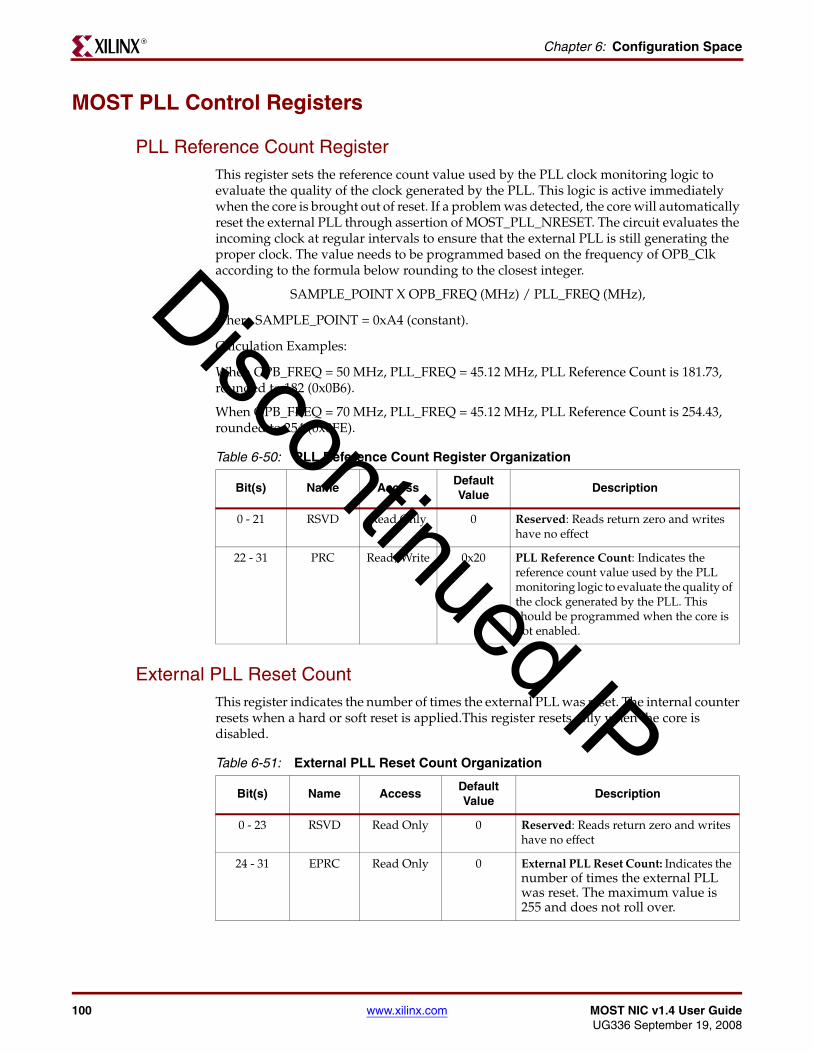
100 www.xilinx.com MOST NIC v1.4 User GuideUG336 September 19, 2008
Chapter 6: Configuration SpaceR
MOST PLL Control Registers
PLL Reference Count RegisterThis register sets the reference count value used by the PLL clock monitoring logic to evaluate the quality of the clock generated by the PLL. This logic is active immediately when the core is brought out of reset. If a problem was detected, the core will automatically reset the external PLL through assertion of MOST_PLL_NRESET. The circuit evaluates the incoming clock at regular intervals to ensure that the external PLL is still generating the proper clock. The value needs to be programmed based on the frequency of OPB_Clk according to the formula below rounding to the closest integer.
SAMPLE_POINT X OPB_FREQ (MHz) / PLL_FREQ (MHz),
where SAMPLE_POINT = 0xA4 (constant).
Calculation Examples:
When OPB_FREQ = 50 MHz, PLL_FREQ = 45.12 MHz, PLL Reference Count is 181.73, rounded to 182 (0x0B6).
When OPB_FREQ = 70 MHz, PLL_FREQ = 45.12 MHz, PLL Reference Count is 254.43, rounded to 254 (0x0FE).
External PLL Reset CountThis register indicates the number of times the external PLL was reset. The internal counter resets when a hard or soft reset is applied.This register resets only when the core is disabled.
Table 6-50: PLL Reference Count Register Organization
Bit(s) Name AccessDefault Value
Description
0 - 21 RSVD Read Only 0 Reserved: Reads return zero and writes have no effect
22 - 31 PRC Read/Write 0x20 PLL Reference Count: Indicates the reference count value used by the PLL monitoring logic to evaluate the quality of the clock generated by the PLL. This should be programmed when the core is not enabled.
Table 6-51: External PLL Reset Count Organization
Bit(s) Name AccessDefault Value
Description
0 - 23 RSVD Read Only 0 Reserved: Reads return zero and writes have no effect
24 - 31 EPRC Read Only 0 External PLL Reset Count: Indicates the number of times the external PLL was reset. The maximum value is 255 and does not roll over.
Discontinued IP

MOST NIC v1.4 User Guide www.xilinx.com 101UG336 September 19, 2008
Transmit / Receive BufferR
Transmit / Receive Buffer
Transmit BufferThis portion of the memory map allows for FIFO based access to the transmit buffers. Sufficient memory map address space is provided to allow random access to the transmit buffer or to allow incrementing of addresses in the case of a burst transaction. However, the core is currently implemented to provide FIFO based access to the transmit buffer.
The transmit buffer is organized on a logical channel basis. The transmit buffer supports a total of 16 logical channels. Each buffer contains 32 words. To ease in programming, the Logical Channel Number forms the 3rd Most Significant Nibble of the Transmit Buffer Address. As such the address space supports 64 words per logical channel, where an access to any word in the space is forwarded to the appropriate channel, even though the underlying memory content is only 32 words deep. Table 6-52 describes the Transmit Buffer memory map.
Accessing the Transmit Buffer
The logical channel transmit buffers must be accessed as a FIFO - that is each word for transmission must be written to the appropriate FIFO in sequential order. The lowest 8 bits
Table 6-52: Transmit Buffer Memory Map
Logical Channel #
Function AddressSize
(Words)Access
0x0 OPB access C_BASEADDR + 0x1000 64 OPB Write; MOST Read
0x1 OPB access C_BASEADDR + 0x1100 64 OPB Write; MOST Read
0x2 OPB access C_BASEADDR + 0x1200 64 OPB Write; MOST Read
0x3 OPB access C_BASEADDR + 0x1300 64 OPB Write; MOST Read
0x4 OPB access C_BASEADDR + 0x1400 64 OPB Write; MOST Read
0x5 OPB access C_BASEADDR + 0x1500 64 OPB Write; MOST Read
0x6 OPB access C_BASEADDR + 0x1600 64 OPB Write; MOST Read
0x7 OPB access C_BASEADDR + 0x1700 64 OPB Write; MOST Read
0x8 Streaming Ingress C_BASEADDR + 0x1800 64 STR Write; MOST Read
0x9 Streaming Ingress C_BASEADDR + 0x1900 64 STR Write; MOST Read
0xA Streaming Ingress C_BASEADDR + 0x1A00 64 STR Write; MOST Read
0xB Streaming Ingress C_BASEADDR + 0x1B00 64 STR Write, MOST Read
0xC OPB access/ Streaming Egress
C_BASEADDR + 0x1C00 64 OPB Write; STR Read
0xD OPB access/ Streaming Egress
C_BASEADDR + 0x1D00 64 OPB Write; STR Read
0xE OPB access/ Streaming Egress
C_BASEADDR + 0x1E00 64 OPB Write; STR Read
0xF OPB access/ Streaming Egress
C_BASEADDR + 0x1F00 64 OPB Write; STR Read
Discontinued IP

102 www.xilinx.com MOST NIC v1.4 User GuideUG336 September 19, 2008
Chapter 6: Configuration SpaceR
of the address are ignored when accessing the transmit buffer. The only bits of significance are the logical channel bits.
The bytes within each word are ordered as follows
The first word written to the transmit buffer will be the first word transmitted on theMOST ring.
Transmit Synchronous Message Format
Synchronous data has no header information; the content is raw data. As such the transmit buffer is written with data ordered as indicated in Table 6-53. A user always writes data in words. The last word may contain less than 4 bytes of actual data. In such a case the user should pad unused data locations with 0x00 in order to mute the channel on completion of transmission.
Transmit Asynchronous Message Format
Asynchronous data contains a header field for the destination address, length and source address, followed by data. The format is as follows:
The first word of the Asynchronous message contains the destination address, and length. The hardware will only transmit as many bytes as indicated by length. Length is calculated in the following way:
Length (in bytes) = (Packet Length -1)*4 +2
The second word of the transmit asynchronous message contains the Source address.
The 3rd to Nth word contains the actual data of the transmit message. A user always writes data in words. The last word may contain less than 4 bytes of actual data. In such a case the user should pad unused data locations with 0x00.
The asynchronous message CRC is calculated and appended automatically by hardware.
Table 6-53: Transmit Buffer Byte Organization
0 - 7 8 - 15 16- 23 24 - 31
Byte N Byte N+1 Byte N+2 Byte N+3
Table 6-54: Asynchronous Message: First Word (Header)
0-15 16-23 24-31
Destination Address Length RSVD
Table 6-55: Asynchronous Message: Second Word (Header)
0-15 16-31
Source Address RSVD
Table 6-56: Asynchronous Message: Third to Nth Word
0 - 7 8 - 15 16- 23 24 - 31
Data Byte N Data Byte N+1 Data Byte N+2 Data Byte N+3
Discontinued IP

MOST NIC v1.4 User Guide www.xilinx.com 103UG336 September 19, 2008
Transmit / Receive BufferR
The TXBER will indicate any overflow or underflow error conditions on a logical channel basis. If enabled, the TXBUFERR in the MISR will be asserted on any TX buffer errors.
Receive BufferThis portion of the memory map allows for FIFO based access to the receive buffers. Sufficient memory map address space is provided to allow random access to the receive buffer. However, the core is currently implemented to provide FIFO based access to the receive buffer.
The receive buffer is organized on a logical channel basis. The receive buffer supports a total of 16 logical channels. Each buffer contains 32 words. To ease in programming the Logical Channel Number forms the 3rd Most Significant Nibble of the Receive Buffer Address. As such the address space supports 64 words per logical channel, where an access to any word in the space is forwarded to the appropriate channel, even though the underlying memory content is only 32 words deep. Table 6-57 defines the Receive Buffer Memory Map.
Table 6-57: Receive Buffer Memory Map
Logical Channel
Function AddressSize
(words)Access
0x0 OPB access C_BASEADDR + 0x2000 64 MOST Write/OPB Read
0x1 OPB access C_BASEADDR + 0x2100 64 MOST Write/OPB Read
0x2 OPB access C_BASEADDR + 0x2200 64 MOST Write/OPB Read
0x3 OPB access C_BASEADDR + 0x2300 64 MOST Write/OPB Read
0x4 OPB access C_BASEADDR + 0x2400 64 MOST Write/OPB Read
0x5 OPB access C_BASEADDR + 0x2500 64 MOST Write/OPB Read
0x6 OPB access C_BASEADDR + 0x2600 64 MOST Write/OPB Read
0x7 OPB access C_BASEADDR + 0x2700 64 MOST Write/OPB Read
0x8 OPB access/
Streaming Ingress
C_BASEADDR + 0x2800 64 STR Write/OPB Read
0x9 OPB access/
Streaming Ingress
C_BASEADDR + 0x2900 64 STR Write/OPB Read
0xA OPB access/
Streaming Ingress
C_BASEADDR + 0x2A00 64 STR Write/OPB Read
0xB OPB access/
Streaming Ingress
C_BASEADDR + 0x2B00 64 STR Write. OPB Read
0xC Streaming Egress C_BASEADDR + 0x2C00 64 MOST Write. STR Read
0xD Streaming Egress C_BASEADDR + 0x2D00 64 MOST Write. STR Read
0xE Streaming Egress C_BASEADDR + 0x2E00 64 MOST Write. STR Read
0xF Streaming Egress C_BASEADDR + 0x2F00 64 MOST Write. STR Read
Discontinued IP

104 www.xilinx.com MOST NIC v1.4 User GuideUG336 September 19, 2008
Chapter 6: Configuration SpaceR
Accessing the Receive Buffer
The logical channel receive buffers must be accessed as a FIFO; that is, each word for reception must be read from the appropriate FIFO in sequential order. The lowest 8 bits of the address are ignored when accessing the receive buffer. The only bits of significance are the logical channel bits. Table 6-58 defines the byte organization of the Receive Buffer. The first word read from the receive buffer is the first word received on the MOST ring.
Receive Synchronous Message Format
Synchronous data has no header information. The content is raw data. As such the receive buffer is read with data ordered as indicated in Table 6-58. A user always reads data in words. The last word may contain less than 4 bytes of actual data.
Receive Asynchronous Message Format
Asynchronous data contains a header field for the destination address, length, source address and address mode, followed by data, followed by the CRC, and including a status field. Table 6-59 defines the format.
The first word of the receive asynchronous message contains the Destination address and Length. The hardware will only receive as many bytes as indicated by Length. The second word of the receive asynchronous message contains the Source address.
The 3rd to Nth word contains the actual data of the receive message. A user always reads data in words. The last word may contain less than 4 bytes of actual data. In such a case the unused data locations will be padded with 0x00.
Table 6-58: Receive Buffer Byte Organization
0 - 7 8 - 15 16- 23 24 - 31
Byte N Byte N+1 Byte N+2 Byte N+3
Table 6-59: Asynchronous Message: First Word (Header)
0-15 16-23 24-31
Destination Address Length RSVD
Table 6-60: Asynchronous Message: Second Word (Header)
0-15 16-31
Source Address RSVD
Table 6-61: Asynchronous Message: Third to Nth Word
0 - 7 8 - 15 16- 23 24 - 31
Data Byte N Data Byte N+1 Data Byte N+2 Data Byte N+3
Discontinued IP

MOST NIC v1.4 User Guide www.xilinx.com 105UG336 September 19, 2008
Transmit / Receive BufferR
The last word contains the status for the message. CRC checking is done by hardware and reported. Status is encoded as defined in Tables 6-62 and 6-63.
The RXBER indicates any overflow or underflow error conditions on a logical channel basis. If enabled, the RXBUFERR in the MISR will be asserted on any RX buffer errors.
Interrupt Processing for Receive Asynchronous Data
Receive Asynchronous data can be shorter than the Full Word Count trigger. However, a user will want to be notified and receive this packet of data before the full word count threshold is crossed by receiving subsequent asynchronous packets.
When the end of an asynchronous packet is reached, the RXASYNEOP interrupt is triggered. The internal logic pads the buffer up to the next word count location in the buffer, and the word count logic is also reset.
The Logical Channel Buffer interrupt for an asynchronous buffer is triggered only when the word count threshold is crossed. The RXASYNEOP interrupt is triggered on every end of asynchronous packet reception.
The user only has to read the valid data of the packet. After the user reads the last word (which contains the status), the buffer is automatically cleared up to the next word count boundary.
Table 6-62: Asynchronous Message: Last Word
0 - 3 4 - 7 8 - 31
RSVD Status RSVD
Table 6-63: Status Encoding
Value Meaning
0000b RX message is valid
0001b RX message has a CRC error
001xb RX message has a length error
0100b - 1111b reserved - not used
Discontinued IP

106 www.xilinx.com MOST NIC v1.4 User GuideUG336 September 19, 2008
Chapter 6: Configuration SpaceR
Discontinued IP

MOST NIC v1.4 User Guide www.xilinx.com 107UG336 September 19, 2008
Configuring the ControllerR
Chapter 7
Programming the Core
This chapter describes how to program the MOST controller for a variety of operations.
Configuring the Controller
For a Ring (Slave)After a hard or soft reset, follow these steps to configure the controller for a ring (slave):
1. Ensure the core is reset by writing a ‘1’ to the SRST bit. This resets the core and forces MENA to be negated. This can be read back via the SRR.
2. Write a ‘0’ to the SRST bit, and a ‘0’ to the MENA to take the core out of reset, but allow configuration of the core.
3. Configure the controller for initial Bypass mode by writing ‘0’ to each of MNSLV, RBDT, and LBACK, and ‘1’ into BYPASS.
4. Program PRCR based on the OPB clock frequency and PLL clock frequency.
5. Program the logical address in the LAR.
6. Program the alternate address in the AAR.
7. Program the group address in the GAR.
8. Program the message retry count in the MRCDR.
9. Confirm the status of the controller by reading the SR, which reports the current state of the core. To read back what was programmed to the core, read MSR.
10. Enable appropriate interrupts by writing ‘1’ to locations as needed in the MIER
11. Clear all MOST interrupts by writing 0xFFFF to the MICR
12. Enable the controller by writing a ‘0’ to SRST and ‘1’ to MENA. The core then operates in Bypass mode, which allows synchronization without disturbing the ring.
13. Via interrupts or polling, confirm full synchronization is achieved by reading the SR. The SBLCK, BLCK, and FLCK bits indicate the synchronization level.
14. After synchronization is achieved, disable the controller again by writing ‘0’ into both SRST and MENA.
15. Configure the controller to Normal mode by writing ‘0’ to each of MNSLV, RBDT, LBACK, and BYPASS.
16. Re-enable the controller by writing a ‘0’ to SRST and ‘1’ to MENA. The core then starts Normal operations.
17. Read the value for the synchronous boundary descriptor in the CCR.
18. Read the value for the delay and position registers in the MCPDR.
Discontinued IP
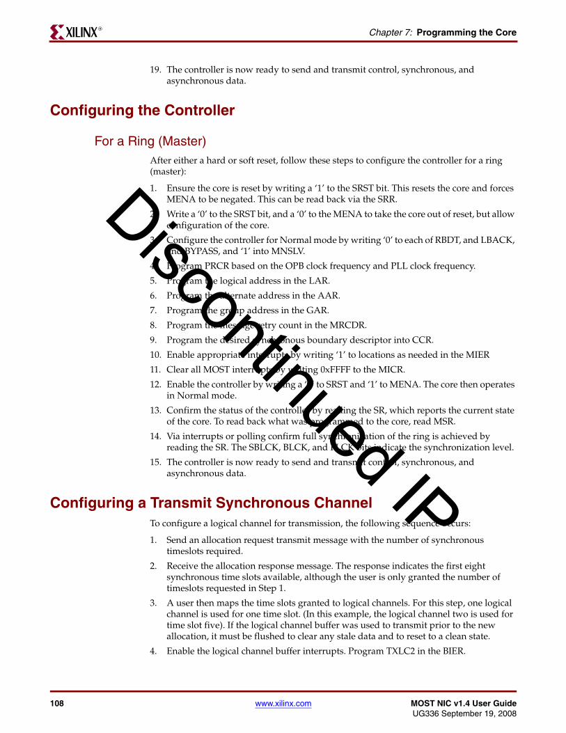
108 www.xilinx.com MOST NIC v1.4 User GuideUG336 September 19, 2008
Chapter 7: Programming the CoreR
19. The controller is now ready to send and transmit control, synchronous, and asynchronous data.
Configuring the Controller
For a Ring (Master)After either a hard or soft reset, follow these steps to configure the controller for a ring (master):
1. Ensure the core is reset by writing a ‘1’ to the SRST bit. This resets the core and forces MENA to be negated. This can be read back via the SRR.
2. Write a ‘0’ to the SRST bit, and a ‘0’ to the MENA to take the core out of reset, but allow configuration of the core.
3. Configure the controller for Normal mode by writing ‘0’ to each of RBDT, and LBACK, and BYPASS, and ‘1’ into MNSLV.
4. Program PRCR based on the OPB clock frequency and PLL clock frequency.
5. Program the logical address in the LAR.
6. Program the alternate address in the AAR.
7. Program the group address in the GAR.
8. Program the message retry count in the MRCDR.
9. Program the desired synchronous boundary descriptor into CCR.
10. Enable appropriate interrupts by writing ‘1’ to locations as needed in the MIER
11. Clear all MOST interrupts by writing 0xFFFF to the MICR.
12. Enable the controller by writing a ‘0’ to SRST and ‘1’ to MENA. The core then operates in Normal mode.
13. Confirm the status of the controller by reading the SR, which reports the current state of the core. To read back what was programmed to the core, read MSR.
14. Via interrupts or polling confirm full synchronization of the ring is achieved by reading the SR. The SBLCK, BLCK, and FLCK bits indicate the synchronization level.
15. The controller is now ready to send and transmit control, synchronous, and asynchronous data.
Configuring a Transmit Synchronous ChannelTo configure a logical channel for transmission, the following sequence occurs:
1. Send an allocation request transmit message with the number of synchronous timeslots required.
2. Receive the allocation response message. The response indicates the first eight synchronous time slots available, although the user is only granted the number of timeslots requested in Step 1.
3. A user then maps the time slots granted to logical channels. For this step, one logical channel is used for one time slot. (In this example, the logical channel two is used for time slot five). If the logical channel buffer was used to transmit prior to the new allocation, it must be flushed to clear any stale data and to reset to a clean state.
4. Enable the logical channel buffer interrupts. Program TXLC2 in the BIER.
Discontinued IP

MOST NIC v1.4 User Guide www.xilinx.com 109UG336 September 19, 2008
Transmitting Synchronous or Asynchronous DataR
5. Program the routing table. Program time slot five (Address C_BASEADDR + 0x0204) to be set to logical channel two by programming the appropriate byte with 0x02.
6. Prime the logical channel buffer as described below.
7. Enable the logical channel by writing a 1 to TXELC2 in the Logical Channel Enable Register (LCE). At the next frame boundary, the controller starts to transmit data from the logical channel buffer on to the MOST ring.
8. Queue data for transmission by writing logical channel two’s transmit buffer as buffer interrupts are received.
Transmitting Synchronous or Asynchronous DataTo transmit data in conjunction with the configuration sequence above, use the following seqeuence:
1. After reset, initialize the configuration and interrupt control registers as required.
2. Enable the core for Normal mode, and assert MENA in the SRR.
3. Allocate channels for synchronous data via sending allocation control messages.
4. Program the routing table (CRT) as required.
5. Prime the Logical Channel Buffer with data. Ideally the user would fill the entire buffer with valid transmit data. At a minimum, at least an empty word’s count worth of data should be written to the logical channel buffer, or an entire asynchronous packet when the packet is smaller than this value.
6. Enable the appropriate logical channel enable (LCE) as required
7. At the next Start of Frame, the data in the transmit logical channel buffer starts to be consumed. An appropriate interrupt from the BISR is asserted depending on the number of free locations in the transmit buffer. If the user primed the buffer with a full 32 words, an interrupt is not generated until at least a word’s count of data had been transmitted.
8. The Interrupt routine should then do the following:
a. Clear the interrupt by writing the BICR.
b. Write data to the appropriate transmit buffer. Table 6-52, page 101 indicates the address to use. All accesses must be word accesses. As many words should be written to satisfy the logical channel word count settings (see Table 4-2). If the C_EWC is set to ‘16,’ then at least 16 words should be written. If the C_EWC is to ‘8,’ then at least 8 words should be written (or until the end of an asynchronous packet).
c. In the case of the asynchronous channel 0, the controller arbitrates on the ring to send the asynchronous packet after the first two words of the packet are available. The controller also automatically pads out the last frame in the packet, and triggers ATXASYNEOP to alert the application that the packet has exited the core.
9. A new interrupt is generated when the C_EWC threshold is reached again.
Note: If a bit in the MISR is asserted, and a second interrupt for that bit is triggered, the second interrupt will be hidden in the first. Failure to service interrupts when they are first triggered will result in a memory leak for that buffer.
Receiving Synchronous DataTo receive data on a synchronous logical channel, the following seqeuence occurs:
Discontinued IP
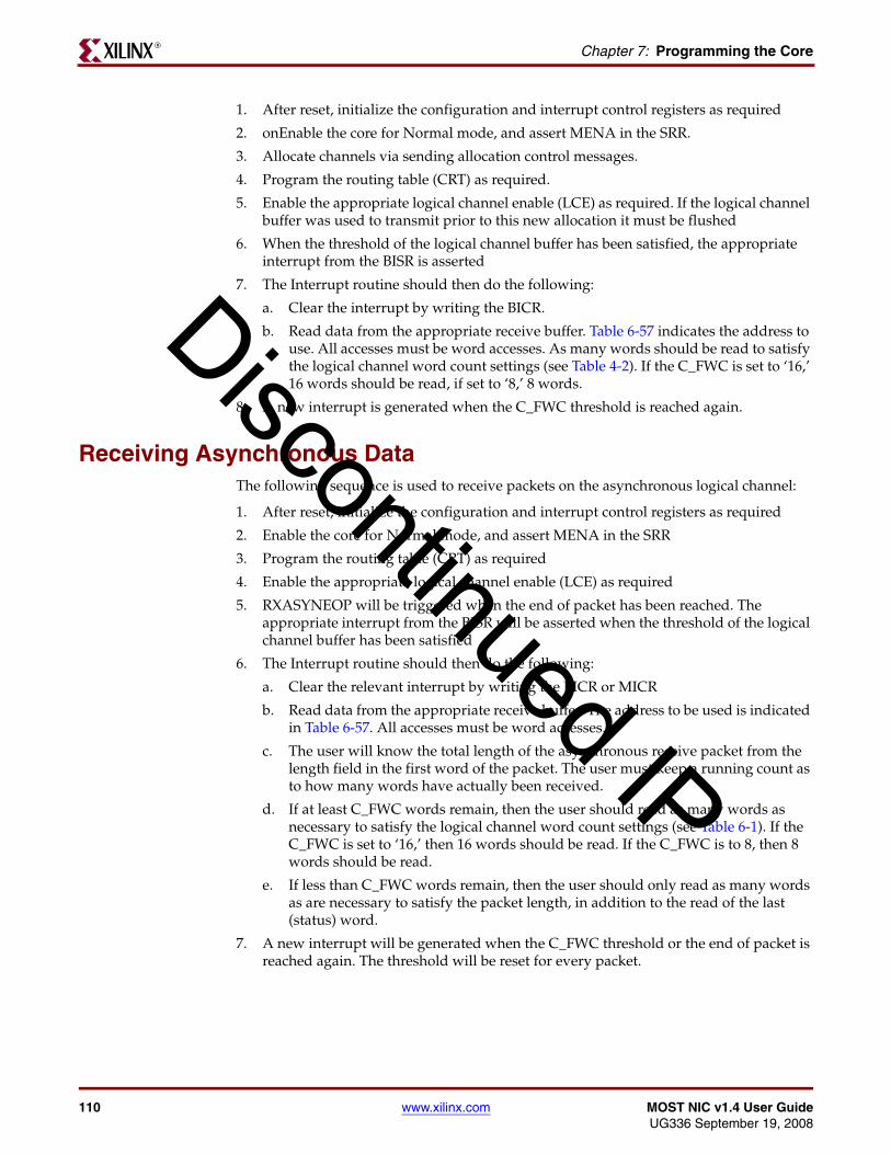
110 www.xilinx.com MOST NIC v1.4 User GuideUG336 September 19, 2008
Chapter 7: Programming the CoreR
1. After reset, initialize the configuration and interrupt control registers as required
2. onEnable the core for Normal mode, and assert MENA in the SRR.
3. Allocate channels via sending allocation control messages.
4. Program the routing table (CRT) as required.
5. Enable the appropriate logical channel enable (LCE) as required. If the logical channel buffer was used to transmit prior to this new allocation it must be flushed
6. When the threshold of the logical channel buffer has been satisfied, the appropriate interrupt from the BISR is asserted
7. The Interrupt routine should then do the following:
a. Clear the interrupt by writing the BICR.
b. Read data from the appropriate receive buffer. Table 6-57 indicates the address to use. All accesses must be word accesses. As many words should be read to satisfy the logical channel word count settings (see Table 4-2). If the C_FWC is set to ‘16,’ 16 words should be read, if set to ‘8,’ 8 words.
8. A new interrupt is generated when the C_FWC threshold is reached again.
Receiving Asynchronous DataThe following sequence is used to receive packets on the asynchronous logical channel:
1. After reset, initialize the configuration and interrupt control registers as required
2. Enable the core for Normal mode, and assert MENA in the SRR
3. Program the routing table (CRT) as required
4. Enable the appropriate logical channel enable (LCE) as required
5. RXASYNEOP will be triggered when the end of packet has been reached. The appropriate interrupt from the BISR will be asserted when the threshold of the logical channel buffer has been satisfied
6. The Interrupt routine should then do the following:
a. Clear the relevant interrupt by writing the BICR or MICR
b. Read data from the appropriate receive buffer. The address to be used is indicated in Table 6-57. All accesses must be word accesses.
c. The user will know the total length of the asynchronous receive packet from the length field in the first word of the packet. The user must keep a running count as to how many words have actually been received.
d. If at least C_FWC words remain, then the user should read as many words as necessary to satisfy the logical channel word count settings (see Table 6-1). If the C_FWC is set to ‘16,’ then 16 words should be read. If the C_FWC is to 8, then 8 words should be read.
e. If less than C_FWC words remain, then the user should only read as many words as are necessary to satisfy the packet length, in addition to the read of the last (status) word.
7. A new interrupt will be generated when the C_FWC threshold or the end of packet is reached again. The threshold will be reset for every packet.
Discontinued IP

MOST NIC v1.4 User Guide www.xilinx.com 111UG336 September 19, 2008
Flushing a Synchronous or Asynchronous BufferR
Flushing a Synchronous or Asynchronous Buffer
To Remove the Data in the Current StreamThe following sequence is used to flush a buffer when the data in the buffer is no longer desired:
1. Determine the current active channels by reading the logical channel enable (LCE) register.
2. Write the returned value back to the LCE by setting the bit for the desired logical to 0
3. Flush the appropriate logical channel buffers by writing the Flush Control Register (FCR) with the appropriate Logical Channel Number (FCHN), direction (FDIR) and the flush bit (FLCB). This will reset the pointers in the buffer and reset the word count values in that the channel. For asynchronous data in receive logical channel 0, the flush needs to occur after receiving the ASYNCEOP interrupt to ensure that the incoming packet is not partially flushed.
4. If it is a transmit logical channel, prime the buffer as described above in Transmitting Synchronous or Asynchronous Data
5. Determine the current active channels by reading the logical channel enable (LCE) register.
6. Write the returned value back to the LCE by setting the bit for the desired logical to ‘1’
Due to an Overflow or Underflow ConditionThe following sequence is used to flush a buffer due to an underflow or overflow condition
1. After reset, initialize the configuration and interrupt control registers as required
2. Enable the core for Normal mode, and assert MENA in the SRR
3. Allocate channels via sending allocation control messages
4. Program the routing table (CRT) as required
5. Enable the appropriate logical channel enable (LCE) as required
6. Enable the RXBUFERR and TXBUFERR bits in the Most Interrupt Enable Register (MIER)
7. The appropriate interrupt from the BISR will be asserted when either an underflow or overflow condition has occurred
8. The Interrupt routine should then do the following:
a. Read the TXBER for Transmit buffer issues, and the RXBER for Receive buffer issues. These registers will indicate which logical channel buffer overflow or underflowed.
b. Disable the appropriate logical channel by setting the corresponding bit in the Logical Channel Enable Register (LCE) to ‘0’.
c. Flush the appropriate logical channel buffers by writing the Flush Control Register (FCR) with the appropriate Logical Channel number (FCHN), direction (FDIR) and the flush bit (FLCB). This will reset the pointers in the buffer and reset the corresponding bit in the TXBER or RXBER register
d. Clear the interrupt by writing the MICR
Discontinued IP

112 www.xilinx.com MOST NIC v1.4 User GuideUG336 September 19, 2008
Chapter 7: Programming the CoreR
9. As it is likely that the error condition may have been triggered by an error condition in the ring, it is recommended that the user deallocate all timeslots for the logical channel, and restart the sequence of configuring a logical channel.
Using the Streaming PortsWhen using the streaming port interfaces, the following considerations occur:
1. First, the user must configure the logical channel for the streaming port
a. If the data is being received from the MOST ring or transmitted to the MOST ring, follow the sequence to configure the logical channels as above. The interrupt procedure for the OPB interface does not need to be followed, since the OPB interface will never see the data transfers on this interface. However, any priming procedures must still be followed
b. If the data is being received from the OPB interface or transmitted to the OPB interface, all that needs to be done is to enable the correct bit in the logical channel enable (LCE), because no data is seen on the ring. However, the interrupt procedure for data reception/transmission on the OPB interface must still be followed.
2. When the user asserts OPB_Rst, this is passed to the user as STR_RST.
3. When a buffer is flushed for any reason, this notification is passed along to the user as rising edge transition on STR_<interface>_BIF_AVAIL, where there is a specific bit for each logical channel. The core will not transfer any data when this signal is low.
4. For the TX and RX datapaths, the ingress and egress channels share common resources. The means that only the ingress or the egress may be active at any given time. For both datapaths, ingress has higher priority over egress, which ensures that neither interface will be starved when both are active.
5. When changing the logical channel on an egress port, one cycle of dead time where <interface>_DST_RDY is deasserted is required.
6. While the signaling for these interfaces is LocalLink, word count interrupts are provided to the user for use in determine full or empty status in the buffers. <interface>_SRC_RDY and <interface>_DST_RDY are deasserted when the core is unable to accept/transmit data. This determination is combined across logical channels, which means for example, that a full ingress buffer will block any ingress buffer.
Control Message Procedure
Transmit Message ProcedureAfter a controller has been configured, communication between the controllers is required to obtain information about configuration and to send/receive control messages to request allocation time slots, and so forth.
To add new Control Transmit Messages, the following sequence occurs:
1. Poll the Control Transmit Status Register (CTXS) occupancy bits (CTXOCC) until the occupancy is ‘0,’ which indicates that there is room for a new transmit control message.
2. Write as many words as necessary in the order described above to the Control Transmit FIFO (CTXFIFO).
Discontinued IP

MOST NIC v1.4 User Guide www.xilinx.com 113UG336 September 19, 2008
Control Message ProcedureR
3. When all words have been written to the CTXFIFO, set the new message bit (CNEWTX) in the Control Transmit Status Register (CTXS). This will queue the transmit message for transmission on the MOST ring. The occupancy bit (CTXOCC) is set to ‘1’ after the CNEWTX bit is written.
4. An interrupt (CTLTKFREE) is asserted after a message is de-queued from the Control Transmit FIFO. The CTXOCC is deasserted at the same time.
5. The user receives either a CTLTXOK interrupt (if successful) or a CTLTXFAIL interrupt (if not successful) to indicate the success of message transmission. Only one of these two interrupts is asserted for each transmit message. The core automatically attempts to retransmit messages according to the gap and retry programming set by the user in MRCDR.
6. On completion, the entire message is returned to the user, including the original request, response, and transmission status in the CTXRESFIFO
Note: No overflow notification or protection is provided for writes to a full Control Transmit Message FIFO. Writes to a full FIFO will corrupt the existing contents and may corrupt the state of the control channel in the MOST ring. This also implies that in case of back-to-back transmissions of control messages, the user must read the contents from the CTXRESFIFO within 2 frames of receiving the CTLTXOK interrupt for the first message or this content will be overwritten.
Response Message ProcedureTo read a response for a Control Transmit Message, the following sequence occurs:
1. Either the CTLTXOK and CTLTXFAIL interrupt are asserted on completion of the transmit message and reception of any response and status. A CTLTXFAIL interrupt is only asserted after the message transmission has been retried subject to the value programmed in the MRCDR register.
2. Read seven words in the order defined above from the Transmit Response FIFO (CTXRESFIFO). A valid message has a value of 0x1010 in the TSTAT field, and the entire message is useful. A failed message has a TSTAT value set to the transmission status of the received message for the last transmit attempt (not equal to 0x1010), and the response portion may be missing.
Note: No underflow notification or protection is provided for reads to an empty Transmit Response FIFO Reads to an empty FIFO corrupt future transmit response reception.
Receive Message ProcedureTo read new normal Control Receive Messages, the following sequence is used. Note that low-level messages, for example, allocation and deallocation, are directly handled by the core, and do not go to the user.
1. A CTLRXNEW interrupt is asserted on reception of each new receive control message. The CRXOCC is set to ‘1’ at the same time. Wait for the interrupt indicating a new Control Message has been received.
2. Optionally, read the Control Receive Status Register (CRXS) occupancy bits (CRXOCC) to ensure the occupancy is not ‘0’. This indicates if there is any control message to receive.
3. Read six words in the order described above to the Control Receive FIFO (CRXFIFO)
4. When all words have been read from the CRXFIFO, the occupancy is automatically set to ‘0’. If another message was received in the time it took to read the first message and clear the interrupt, the occupancy automatically accounts for this. If the occupancy bit
Discontinued IP

114 www.xilinx.com MOST NIC v1.4 User GuideUG336 September 19, 2008
Chapter 7: Programming the CoreR
(CRXOCC) is still ‘1,’ another message is available in the CRXFIFO. If CRXOCC is ‘0,’ no more messages are available.
5. If the CRXFIFOs are not serviced by the user, the core will not acknowledge (NAK) messages it receives until room is made available.
Note: No underflow notification or protection is provided for reads to an empty Control Receive Message FIFO. Reads to an empty FIFO will corrupt future message reception.
Flushing a Control Buffer due to a Deadlock ConditionThe following sequence is used to flush a control buffer. In general, flushing of control buffers is not recommended, however, if a deadlock state occurs where a very low priority message is not able to win arbitration, this method can be used to allow the high priority message to be transmitted.
1. The user must set a software timer to determine that this condition will be necessary
2. The user must then wait for an interrupt. A CTLTXOK interrupt will mean that the message was finally transmitted. A CTLTXFAIL will indicate that the retry count has been exceeded, and the message has been flushed automatically. Nothing more needs to be done for these first two conditions. A CTLARBLST will indicate that this low priority message has failed again- the rest of the steps must be followed.
3. The user must flush the transmit control buffers by writing the Flush Control Register (FCR) with the appropriate Logical Channel Number (FCHN), direction (FDIR) and the flush bit (FLCB). This event must occur within a few frames of receiving the CTLARBLST to ensure that the ring is not corrupted.
4. All messages written to the control buffers will then be flushed. The user must reload the messages in the new order, with the high priority message first.
Controlling the State of Light on the Ring
Stopping the Transmission of Light on the RingThe following sequence is used to ensure that there is no light on an inactive ring
1. At some point the Application layer will decide to stop transmitting data.
2. Ensure there is no more TX activity in the core- deallocate all channels, and cease writing to the transmit buffers (logical channel and control), which will minimize the number of active nodes in the device
3. To force zero transmission at any time, the DAZ bit can be set in any mode with the exception of BYPASS.
Starting the Reception of Light from the RingThe following sequence is used to enter into Normal mode from an inactive ring
1. At some point, the FOT will detect light, and this will trigger the LONCHG interrupt in the MISR
2. The user can then use the correct sequence in configuring the core to regain synchronization
Discontinued IP

MOST NIC v1.4 User Guide www.xilinx.com 115UG336 September 19, 2008
Configuring the Controller for Test ModesR
Starting the Transmission of Light to the RingThe following sequence is used to start traffic on an inactive ring
1. Force the core to master or a pseudo-master by setting MNSLV to ’1,’ BYPASS and LBACK to ‘0,’ and RBDT to ‘0’ for a Master/Slave core and to ‘1’ for a Slave only core.
2. The core will start sending empty frames. Eventually, when the ring is complete, the FOT will detect light and this will trigger the LONCHG interrupt
3. The user can then use the correct sequence in configuring the core to get back into normal mode for re-synchronization.
Configuring the Controller for Test Modes
Ring Break DiagnosticsThe procedure for Ring Break Testing is specified in the MOST Specification. The core is enabled to assist the user in this mode.
1. Ensure the core is reset by writing a ‘1’ to the SRST bit. This will reset the core and force MENA to be negated. This can be read back via the SRR.
2. Write a ‘0’ to the SRST bit, and a ‘0’ to the MENA to take the core out of reset, but allow configuration of the core.
3. For a full Master/Slave core or a slave-only, program MNSLV to the desired setting for Ring Break. In addition, program RBDT to ‘1’. Program BYPASS and LBACK to ‘0.’
4. Enable the core by writing ‘1’ to MENA and keeping SRST set to ‘0.’
5. Detect whether the ring is connected by looking for the LON interrupt. For a full Master/Slave core, complete reception is enabled. For a slave-only core, corrupt data will be received, but with the LON interrupt the user will know that there could be reception from that point.
For LoopbackFor any asynchronous or synchronous data, a loopback configuration requires no special considerations. Any control message type with a single-address value can be sent to itself with the core responding appropriately to the message and triggering all of the correct interrupts in the system. Note that because the node acts as both upstream and downstream from itself, the sequence on the transmit side may not reflect exactly a regular transmission to another node. However, the stream of data received by the NIC will always look consistent. The following sequence should be followed after a reset (either hard or soft).
1. Ensure the core is reset by writing a ‘1’ to the SRST bit. This will reset the core and force MENA to be negated. This can be read-back via the SRR.
2. Write a ‘0’ to the SRST bit, and a ‘0’ to the MENA to take the core out of reset, but allow configuration of the core.
3. Configure the controller for immediate transmission by writing ‘0’ to each of BYPASS and RBDT, the desired mode into MNSLV, and ‘1’ into LBACK. This must be done because the core will not be able to lock onto an incoming stream unless the core is also transmitting a stream. Note that the transmit output can be observed on the MOST_TX signal, which is routed internally in the core to the MOST_RX line. No external optical cables are required.
Discontinued IP
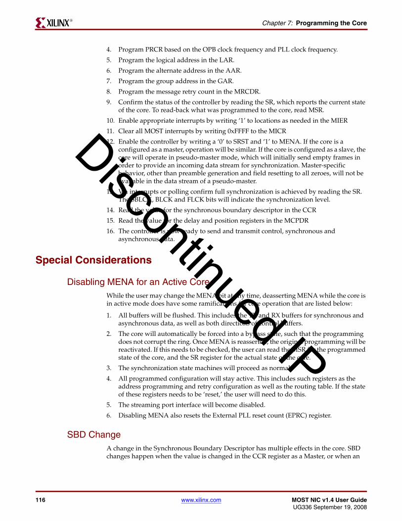
116 www.xilinx.com MOST NIC v1.4 User GuideUG336 September 19, 2008
Chapter 7: Programming the CoreR
4. Program PRCR based on the OPB clock frequency and PLL clock frequency.
5. Program the logical address in the LAR.
6. Program the alternate address in the AAR.
7. Program the group address in the GAR.
8. Program the message retry count in the MRCDR.
9. Confirm the status of the controller by reading the SR, which reports the current state of the core. To read-back what was programmed to the core, read MSR.
10. Enable appropriate interrupts by writing ‘1’ to locations as needed in the MIER
11. Clear all MOST interrupts by writing 0xFFFF to the MICR
12. Enable the controller by writing a ‘0’ to SRST and ‘1’ to MENA. If the core is a configured as a master, operation will be similar. If the core is configured as a slave, the core will operate in pseudo-master mode, which will initially send empty frames in order to provide an incoming data stream for synchronization. Master-specific behavior, other than preamble generation and field resetting to all zeroes, will not be available in the data stream of a pseudo-master.
13. Via interrupts or polling confirm full synchronization is achieved by reading the SR. The SBLCK, BLCK and FLCK bits will indicate the synchronization level.
14. Read the value for the synchronous boundary descriptor in the CCR
15. Read the value for the delay and position registers in the MCPDR
16. The controller is now ready to send and transmit control, synchronous and asynchronous data.
Special Considerations
Disabling MENA for an Active CoreWhile the user may change the MENA bit at any time, deasserting MENA while the core is in active mode does have some ramifications for core operation that are listed below:
1. All buffers will be flushed. This includes the TX and RX buffers for synchronous and asynchronous data, as well as both directions of control buffers.
2. The core will automatically be forced into a bypass state, such that the programming does not corrupt the ring. Once MENA is reasserted, the original programming will be reactivated. If this needs to be checked, the user can read the MSR for the programmed state of the core, and the SR register for the actual state of the core.
3. The synchronization state machines will proceed as normal.
4. All programmed configuration will stay active. This includes such registers as the address programming and retry configuration as well as the routing table. If the state of these registers needs to be ‘reset,’ the user will need to do this.
5. The streaming port interface will become disabled.
6. Disabling MENA also resets the External PLL reset count (EPRC) register.
SBD ChangeA change in the Synchronous Boundary Descriptor has multiple effects in the core. SBD changes happen when the value is changed in the CCR register as a Master, or when an
Discontinued IP

MOST NIC v1.4 User Guide www.xilinx.com 117UG336 September 19, 2008
Special ConsiderationsR
SBDCHG interrupt is detected as a Slave. The following steps should be handled by the user application to ensure that this event does not corrupt the ring.
1. If the MOST NIC is configured as a Master Node, the user should send a deallocate all message to itself. This will ensure that the allocation table stays within the bounds of the current descriptor. MAT registers will be out of date until this occurs, and SAR registers will be out of date until updated by the ring.
2. All nodes should reallocate their synchronous data transmission channels.
3. The user should flush the asynchronous buffer (LC 0), since some messages may be in transmit, and an SBD event will stop the transmission. Any pending messages should be retransmitted.
4. The user should reprogram the CRT to take into affect the new synchronous channel timeslots.
Multicast Addressing for Control Messages While multiple addressing modes of broadcast and groupcast are supported by the NIC, consider the following:
1. Only message types of Normal, Remote Write, and Get Source are supported. If the NIC receives a message with a multicast address that does not match one of these types, it is dropped silently.
2. The NIC never responds to a multicast address for a message it has sent. For this reason, in test modes such as loopback, these messages never result in a successful transmission.
Using the Core in LoopbackWhen using the core in loopback mode, the user software processes both the receive and transmit interrupts at the same time. If the MOST NIC is used in a design where the system clock (OPB_Clk) is slow, there may be difficultly servicing the normal rate interrupts.
1. For asynchronous packets, the lower the SBD value, the more asynchronous data valid in any given frame. In this condition, the user may want to keep the length of the packet down to a value close to the depth of the buffer to prevent underflow/overflow conditions in the buffers when the user routine cannot service both the RX and TX data paths at the same rate.
2. For synchronous data, the user should not try to enable all of the timeslots, particularly on the same logical channel.
3. For control data, there are no limitations. When the RX buffers are filled to capacity, the core automatically retransmits failing TX packets. However, because the node acts as both upstream and downstream to itself, the sequence on the transmit side may not reflect the exact transmission sequence to a different node on the ring. Even so, the stream of data received by the MOST NIC will always look consistent.
Discontinued IP
118 www.xilinx.com MOST NIC v1.4 User GuideUG336 September 19, 2008
Chapter 7: Programming the CoreR
Discontinued IP

MOST NIC v1.4 User Guide www.xilinx.com 119UG336 September 19, 2008
R
Glossary
Click on a letter or scroll down to view the entire glossary.
A B C D F G L M N P P Q R S T U
Glossary of Terms
A
Allocation TableTable with the connection label and active flag for all synchronous channels.
Alternate Address16-bit address used in the asynchronous channel.
Asynchronous ChannelChannel used to send packets between nodes.
B
Bi-phase CodingCoding of a serial data stream using two bi-phase units-per-data bit.
Bi-phase UnitTwo bi-phase units are used to code one data bit.
BlockA group of 16 frames, aligned to a special preamble.
Broadcast AddressA fixed 16-bit address (0x3C8) used in the control message channel.
Discontinued IP
120 www.xilinx.com MOST NIC v1.4 User GuideUG336 September 19, 2008
R
BundleA field used to group asynchronous data spread across multiple frames into a single packet.
BypassA direct connection between Rx and Tx in the MOST NIC that does not modify the MOST signal.
C
Channel (Logical)A collection of time slots or asynchronous data mapped to a transmit or receive buffer.
Channel (Physical)A time slot (byte) in the synchronous field.
Connection labelA tag used by the synchronous channel allocation mechanism to track allocations.
Control Message ChannelChannel used to send messages between nodes.
CRCCyclic Redundancy Check
D
DelayThe number of MOST NICs introducing synchronous data delay, excluding all downstream nodes.
DeviceA MOST NIC with network stack and application.
Downstream NodeA node that is positioned after this node in the ring.
F
Fair CounterCounter whose value is used as part of the arbitration value.
Discontinued IP
MOST NIC v1.4 User Guide www.xilinx.com 121UG336 September 19, 2008
R
FrameThe frame of 64 bytes in size that is sent with the network sample frequency.
G
Groupcast Address16-bit address used in the control message channel to send a message from one node to a group of nodes simultaneously.
L
Logical Address16-bit address used in the control message channel or the asynchronous channel to send a message to a single node.
LSBLeast Significant Bit
M
MasterThe MOST NIC acting as the clock master and synchronization master.
Max DelayNumber of MOST NICs in the node delaying the synchronous field by two frames each.
Max PositionNumber of active MOST NICs in the ring network.
MOSTMedia Oriented Systems Transport
MSBMost Significant Bit
N
Network ServicesSoftware used on top of the MOST NIC.
Discontinued IP

122 www.xilinx.com MOST NIC v1.4 User GuideUG336 September 19, 2008
R
NICNetwork Interface Controller
NodeSame as device.
P
PositionThe position of the MOST NIC in the ring.
Position Address16-bit address used in the control message channel to send a message to a single node selected by its position.
Q
Quadlet4 bytes with aligned to a 4 byte boundary in the synchronous channel.
R
RBDRing Break Diagnosis
RxThe pin on the MOST NIC used to receive the MOST signal.
S
SlaveAn active MOST NIC in the ring network that is not master.
Super BlockA group of 64 Blocks, aligned to a special preamble. Largest repeating pattern in MOST.
Synchronous Boundary DescriptorValue that defines the border between the synchronous field and asynchronous field.
Discontinued IP

MOST NIC v1.4 User Guide www.xilinx.com 123UG336 September 19, 2008
R
Synchronous ChannelChannel used to send streaming data from a single node.
Synchronous Channel Active FlagFlag that indicates whether a MOST NIC is currently transmitting data on a synchronous channel.
Synchronous Data DelayThe delay introduced by buffering the complete synchronous field in the MOST NIC, only to be forwarded two frames later.
T
Transmission StatusHandshaking mechanism used in the control message channel.
TxThe pin on the MOST NIC used to transmit the MOST signal to the next MOST NIC in the MOST ring network.
U
Upstream nodeA node that is positioned before the reference node in the ring.
Discontinued IP

124 www.xilinx.com MOST NIC v1.4 User GuideUG336 September 19, 2008
R
Discontinued IP


