180
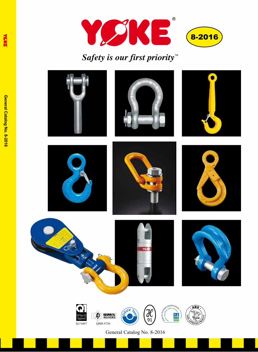
General Catalog No. 8-2016 8-2016 TM Safety is our first priority General Catalog No. 8-2016
| Date post: | 11-Apr-2018 |
| Category: |
Documents |
| Upload: | vuongxuyen |
| View: | 221 times |
| Download: | 2 times |
www.yoke.net
An ISO 9001 Registered Company
TM Safety is our first priority
YOKE products distributed by:
General C
atalog No. 8-2016
YOKE INDUSTRIAL CORP. #39, 33rd Road,
Taichung Industrial Park, Taichung 407,
TAIWAN Tel:+886-4-2350-8088
Fax:+886-4-2350-1001 E-mail: [email protected]
Gen
eral
Cat
alog
No.
8-2
016/
1050
121/
210X
297
Eur
ope-
100
8-2016
TM Safety is our first priority
General Catalog No. 8-2016

Product code
Size
Working Load Limit
Producer logo
size
Warning Application Standard
size
size
NEVER EXCEED PUBLISHED WORKING LOAD LIMIT
WARNINGCopyright © 2016
YOKE Industrial Corp.All Rights Reserved.2

Product code
Size
Working Load Limit
Producer logo
size
Warning Application Standard
size
size
Worldwide Quality Type Approval And Certificate:
NEVER EXCEED PUBLISHED WORKING LOAD LIMIT
WARNINGCopyright © 2016 YOKE Industrial Corp.All Rights Reserved. 3
NEVER EXCEED PUBLISHED WORKING LOAD LIMIT
WARNINGCopyright © 2016
YOKE Industrial Corp.All Rights Reserved.
■■ Magnaflux■Crack■Detection:■
All forged components, each individually
magnaflux detected after heat treatment.
■■ Proof■Load■Testing:■
Chain and components are proof load tested at 2.5 times the Working Load Limits with resultant permanent
deformation within 1%.
■■ Dynamic■Fatigue■Testing:■
Batch samples of chain and components are Dynamic Fatigue Tested at 1.5 times Working Load Limit for
20,000 cycles.
■■ Ultimate■Breaking■Load■Testing:
Batch samples are Break Load Tested in a static tensile testing machine to ultimate failure. The minimum
ultimate force is equal to the Working Load Limit times the safety factor.
■■ Spectrographic■Analysis:
To assure of the proper metallurgy content of all raw materials.
■■ Eddy■Current■Detection:■
All load pins are 100% individually inspected after heat treatment.
Quality Control, Testing, and Detecting during manufacturing
YOKE runs a constant and strict production facility with quality control in every manufacturing stage from raw
materials to the completed product. YOKE is an ISO 9001 certified company and has Type Approval by the major
international authorities from SABS, ZU, ABS, API, and DNV. YOKE has achieved CNLA certification - Chinese
National Laboratory Accreditation which ensures a quality research and development (R&D) department and
unsurpassed product engineering.
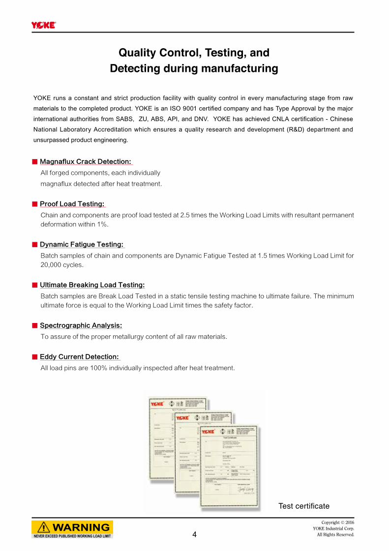
Test certificate
4

NEVER EXCEED PUBLISHED WORKING LOAD LIMIT
WARNINGCopyright © 2016 YOKE Industrial Corp.All Rights Reserved. 5
Copyright © 2016YOKE Industrial Corp.All Rights Reserved. 6

Copyright © 2016YOKE Industrial Corp.All Rights Reserved.
Safety is our first priority ™- Quality, Reliability, Innovation -
Wire Rope Socket
&
Sleeves
DA Shackles
ROV
Hooks, Shackles
Carbon Shackle
Alloy Shackles
Wide Body Shackle
Hoist Rings
&
Lifting Points
Grade 100 Lifting
Chain Fittings
Angular Contact
Bearing Swivels
Hoist Hooks
Snatch Blocks
Hay Fork Pulleys
Trawl & Blocks
Grade 80 Lifting
Chain Fittings
RFF™RingForged-Fabricated™
Heavy Duty Oilfield Sheaves7
Copyright © 2016YOKE Industrial Corp.All Rights Reserved.
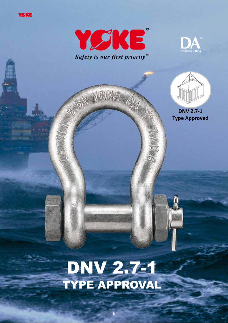
DNV 2.7-1TYPE APPROVAL
DNV 2.7-1Type Approved
8
Offshore Lifting
NEVER EXCEED PUBLISHED WORKING LOAD LIMIT
WARNINGCopyright © 2016 YOKE Industrial Corp.All Rights Reserved.
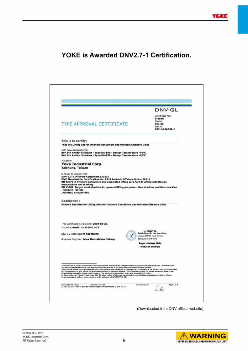
YOKE is Awarded DNV2.7-1 Certification.
(Downloaded from DNV official website)
9

NEVER EXCEED PUBLISHED WORKING LOAD LIMIT
WARNINGCopyright © 2016
YOKE Industrial Corp.All Rights Reserved.
YOKE Industrial Corporation, a market leading designer and manufacturer of lifting components for the oil and gas industry, is excited to announce the launch of its new range of DNV Type Approved Grade 6 and Grade 8 lifting shackles. The bolt, nut and cotter shackles meet DNV Standard 2.7-1 Offshore Containers Specifications and DNV 2.7-3 Portable Offshore Units and come complete with certification.The new range of DATM (DNV Approved) Shackles meet the demanding requirements of the offshore industry, including impact strength of 42J @-40C (DA808). The shackle range DA838 (Grade 6) and DA808 (Grade 8) are closed die forgings, ensuring you receive the performance characteristics and clear embossed markings demanded, for ease of identification for years to come. These markings have become the Riggers choice, and offer you the assurance you need from a forged shackle. YOKE DATM Shackles also comply with the European Standard (EN13889), USA Federal Specifications (RR-C-271F Type IVA Grade A, Class 3) and other international and national standards. YOKE DATM Shackles can also be used in your other day to day lifting applications, giving you the confidence for each and every lift. There is no longer a need for you to carry dual stocks of different shackles; DA808 and DA838 give you the solution to all your needs.YOKE DATM Shackles also offer the highest design factors in the industry, up to 8:1 (DA808), ensuring that you have confidence in every lifting application, even in the harshest environments. Each shackle is supplied with certification as required by DNV. Traceability from the raw material, through the production process to the finished product. YOKE DATM Shackles are clearly embossed with the YOKE brand, WLL, size, traceability code, grade and CE mark. The bolts are also clearly embossed with the YOKE logo, traceability code and grade. Each shackle is hot dipped galvanized to ensure performance in the harshest conditions.Riggers in the industry have long recognized the benefits of the strength, ductility and impact properties of a closed die forged shackle. Embossed markings ensure easy and clear identification for years to come, and traceability against your DNV Offshore Container certificates reduces overall rigging cost.YOKE continues to develop its range of lifting products for critical lifting applications, be it for energy, cold temperature environments, construction, manufacturing, ship building and other demanding industries who continue to call upon YOKE to work with them to provide a safe lifting solution. “Safety is our first priority”
A Grand Announcement of
DNV Type Approved Offshore Container Lifting Shackles
by YOKE
10
NEVER EXCEED PUBLISHED WORKING LOAD LIMIT
WARNINGCopyright © 2016 YOKE Industrial Corp.All Rights Reserved.
The Features of YOKEDATM Offshore Container Lifting Shackles
YOKE DATM Shackles are manufactured to meet the requirements
of DNV 2.7-1 for offshore container lifting to fulfill the need for the
critical requirements of charpy impact, strength and ductility.
Lower Temperature Demand
YOKE DATM Shackles are designed to withstand impacts in extreme
environments up to maximum -40° C.
Higher Safety Factors
YOKE DATM Shackles have a design factor of 6 for Grade 6
Shackles and a design factor of 8 for Grade 8 shackles to enable
them to operate in the harshest environments.
DNV 2.7-1 Specified Test Certificate
Test certificate with material and manufacturing process specified in
DNV 2.7-1 for complete traceability.
To perform in the harshest weather and roughest sea conditions,
YOKE DATM Shackles are specially designed, manufactured and
tested for the operating in the offshore container industry.
11

NEVER EXCEED PUBLISHED WORKING LOAD LIMIT
WARNINGCopyright © 2016
YOKE Industrial Corp.All Rights Reserved.
YOKE Offshore Container Lifting Shackles
DNV 2.7-1 Type Approved
Producer logo
Grade
Size
Batch Code links to Test Certification sheet
DA Series
Working Load Limit
Pin with - producer logo - grade - batch code
12

NEVER EXCEED PUBLISHED WORKING LOAD LIMIT
WARNINGCopyright © 2016 YOKE Industrial Corp.All Rights Reserved.
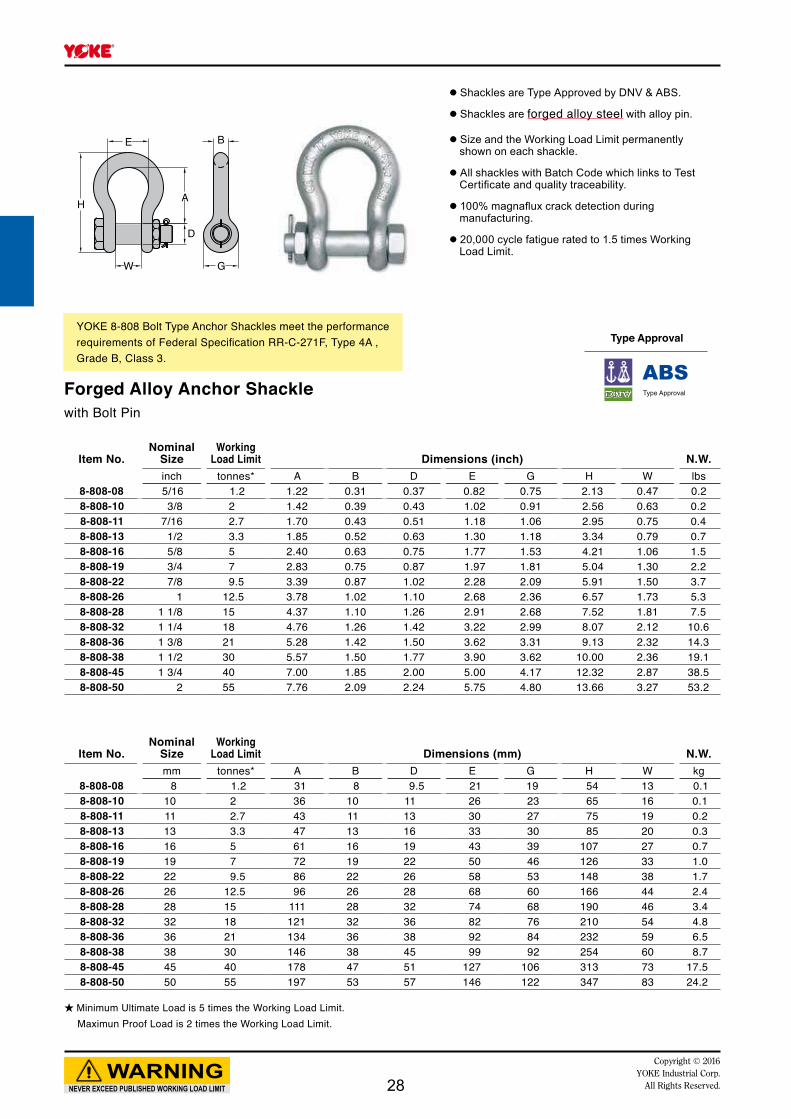
DA 838 Shackle Grade 6 - Meets the following performance requirements:
- DNV 2.7-1 - EN 13889 - U.S. Fed. Spec. RR-C-271F Type IVA, Grade A, Class 3 - ASME B30.26
- Hot dip galvanized - 20,000 cycle fatigue rated to 1.5 times Working Load Limit- Charpy test of 42 joules (31ft. lbs.) at - 20°C ( - 4°F)
-20°C
Item No.Nominal
SizeWorking
Load Limit Dimensions (inch) N.W.inch tonnes* A B D E G H W lbs
DA-838-13 1/2 2.00 1.85 0.52 0.63 1.30 1.18 3.34 0.79 0.9DA-838-16 5/8 3.25 2.40 0.63 0.75 1.70 1.50 4.17 1.06 1.5DA-838-19 3/4 4.75 2.83 0.75 0.87 1.97 1.81 5.04 1.30 2.2DA-838-22 7/8 6.50 3.39 0.87 1.02 2.28 2.09 5.91 1.50 3.7DA-838-26 1 8.50 3.78 1.02 1.10 2.68 2.40 6.57 1.73 5.3DA-838-28 1- 1/8 9.50 4.37 1.10 1.26 2.91 2.68 7.52 1.81 7.5DA-838-32 1- 1/4 12.00 4.76 1.26 1.42 3.30 2.99 8.07 2.12 10.6DA-838-36 1- 3/8 13.50 5.28 1.42 1.50 3.62 3.31 9.13 2.32 14.3DA-838-38 1- 1/2 17.00 5.57 1.50 1.69 3.90 3.62 10.00 2.36 19.4DA-838-45 1- 3/4 25.00 7.00 1.85 2.00 5.00 4.17 12.32 2.87 38.5DA-838-50 2 35.00 7.76 2.09 2.24 5.75 4.80 13.66 3.27 53.2
*Minimum Ultimate Load is 6 times the Working Load Limit.
*Minimum Ultimate Load is 6 times the Working Load Limit.
Item No.Nominal
SizeWorking
Load Limit Dimensions (mm) N.W.mm tonnes* A B D E G H W kg
DA-838-13 13 2.00 47 13 16 33 30 85 20 0.4DA-838-16 16 3.25 61 16 19 43 38 106 27 0.7DA-838-19 19 4.75 72 19 22 50 46 126 33 1.0DA-838-22 22 6.50 86 22 26 58 53 148 38 1.7DA-838-26 26 8.50 96 26 28 68 61 166 44 2.4DA-838-28 28 9.50 111 28 32 74 68 190 46 3.4DA-838-32 32 12.00 121 32 36 84 76 210 54 4.8DA-838-36 36 13.50 134 36 38 92 84 232 59 6.5DA-838-38 38 17.00 146 38 43 99 92 254 60 8.8DA-838-45 45 25.00 178 47 51 127 106 313 73 17.5DA-838-50 50 35.00 197 53 57 146 122 347 83 24.2
13

NEVER EXCEED PUBLISHED WORKING LOAD LIMIT
WARNINGCopyright © 2016
YOKE Industrial Corp.All Rights Reserved.
DA 808 Shackle Grade 8 - Meets the following performance requirements:
- DNV 2.7-1 - EN 13889 - U.S. Fed. Spec. RR-C-271F Type IVA, Grade A, Class 3 - ASME B30.26
- Hot dip galvanized - 20,000 cycle fatigue rated to 1.5 times Working Load Limit- Charpy test of 42 joules (31ft. lbs.) at - 40°C ( - 40°F)
-40°C
*Minimum Ultimate Load is 8 times the Working Load Limit.
*Minimum Ultimate Load is 8 times the Working Load Limit.
Item No.Nominal
SizeWorking
Load Limit Dimensions (inch) N.W.inch tonnes* A B D E G H W lbs
DA-808-13 1/2 2.00 1.85 0.52 0.63 1.30 1.18 3.34 0.79 0.9DA-808-16 5/8 3.25 2.40 0.63 0.75 1.70 1.50 4.17 1.06 1.5DA-808-19 3/4 4.75 2.83 0.75 0.87 1.97 1.81 5.04 1.30 2.2DA-808-22 7/8 6.50 3.39 0.87 1.02 2.28 2.09 5.91 1.50 3.7DA-808-26 1 8.50 3.78 1.02 1.10 2.68 2.40 6.57 1.73 5.3DA-808-28 1- 1/8 9.50 4.37 1.10 1.26 2.91 2.68 7.52 1.81 7.5DA-808-32 1- 1/4 12.00 4.76 1.26 1.42 3.30 2.99 8.07 2.12 10.6DA-808-36 1- 3/8 13.50 5.28 1.42 1.50 3.62 3.31 9.13 2.32 14.3DA-808-38 1- 1/2 17.00 5.57 1.50 1.77 3.90 3.62 10.00 2.36 19.4DA-808-45 1- 3/4 25.00 7.00 1.85 2.00 5.00 4.17 12.32 2.87 38.5DA-808-50 2 35.00 7.76 2.09 2.24 5.75 4.80 13.66 3.27 53.2
Item No.Nominal
SizeWorking
Load Limit Dimensions (mm) N.W.mm tonnes* A B D E G H W kg
DA-808-13 13 2.00 47 13 16 33 30 85 20 0.4DA-808-16 16 3.25 61 16 19 43 38 106 27 0.7DA-808-19 19 4.75 72 19 22 50 46 126 33 1.0DA-808-22 22 6.50 86 22 26 58 53 148 38 1.7DA-808-26 26 8.50 96 26 28 68 61 166 44 2.4DA-808-28 28 9.50 111 28 32 74 68 190 46 3.4DA-808-32 32 12.00 121 32 36 84 76 210 54 4.8DA-808-36 36 13.50 134 36 38 92 84 232 59 6.5DA-808-38 38 17.00 146 38 45 99 92 254 60 8.8DA-808-45 45 25.00 178 47 51 127 106 313 73 17.5DA-808-50 50 35.00 197 53 57 146 122 347 83 24.2
14

Copyright © 2016YOKE Industrial Corp.All Rights Reserved. 15
WC
D1
B
A
L1
D d
KL
Item No.Rope Size Before Swage Dimensions (inch)
Max. AfterSwage Dim. N.W.
S.C.* Galvanized inch A B C D D1 d K L L1 W inch lbs8-730-06 8-730-06G 1/4 1.50 1.38 0.35 0.50 0.67 0.27 4.02 4.80 2.17 0.67 0.46 0.78-730-08 8-730-08G 5/16 1.77 1.65 0.47 0.77 0.79 0.34 5.31 6.26 3.15 0.79 0.71 1.38-730-10 8-730-10G 3/8 1.77 1.65 0.47 0.77 0.79 0.41 5.31 6.26 3.15 0.79 0.71 1.58-730-11 8-730-11G 7/16 1.96 2.00 0.55 0.98 0.98 0.48 6.85 7.83 4.33 1.00 0.91 2.48-730-13 8-730-13G 1/2 1.96 2.00 0.55 0.98 1.19 0.55 6.85 7.83 4.33 1.00 0.91 2.48-730-14 8-730-14G 9/16 2.25 2.36 0.68 1.25 1.19 0.62 8.27 9.45 5.31 1.22 1.16 5.38-730-16 8-730-16G 5/8 2.25 2.36 0.68 1.25 1.19 0.67 8.27 9.45 5.31 1.22 1.16 5.18-730-19 8-730-19G 3/4 2.75 2.75 0.79 1.55 1.38 0.82 10.07 11.61 6.34 1.50 1.42 8.88-730-22 8-730-22G 7/8 3.23 3.15 0.94 1.70 1.63 0.94 11.81 13.39 7.44 1.77 1.55 13.08-730-26 8-730-26G 1 3.86 3.94 1.02 1.98 2.00 1.06 13.58 15.55 8.50 2.00 1.80 20.28-730-28 8-730-28G 1 1/8 4.26 4.06 1.19 2.25 2.20 1.19 15.08 17.40 9.37 2.25 2.05 28.28-730-32 8-730-32G 1 1/4 4.72 4.45 1.34 2.53 2.48 1.33 16.50 19.06 10.59 2.48 2.30 39.28-730-36 8-730-36G 1 3/8 5.20 5.00 1.38 2.80 2.44 1.45 18.23 21.02 11.69 2.52 2.56 48.08-730-38 8-730-38G 1 1/2 5.75 5.51 1.69 3.08 2.52 1.61 19.75 22.88 12.40 3.00 2.81 63.68-730-45 8-730-45G 1 3/4 6.75 6.70 2.11 3.39 3.50 1.86 23.00 26.53 14.88 3.50 3.06 96.88-730-50 8-730-50G 2 8.00 8.00 2.37 3.94 3.75 2.11 26.88 31.44 16.96 4.00 3.56 160.8
Item No.Rope Size Before Swage Dimensions (mm)
Max. AfterSwage Dim. N.W.
S.C.* Galvanized mm A B C D D1 d K L L1 W mm kg8-730-06 8-730-06G 6- 7 38 35 9 13 18 7 102 122 55 17 12 0.38-730-08 8-730-08G 8 45 42 12 20 21 9 135 159 80 20 18 0.68-730-10 8-730-10G 9-10 45 42 12 20 21 10 135 159 80 20 18 0.78-730-11 8-730-11G 11-12 50 50 14 25 25 12 174 199 110 25 23 1.18-730-13 8-730-13G 13 50 50 14 25 25 14 174 199 110 25 23 1.18-730-14 8-730-14G 14-15 57 60 17 32 30 16 210 240 135 31 30 2.48-730-16 8-730-16G 16 57 60 17 32 30 17 210 240 135 31 30 2.38-730-19 8-730-19G 18-20 70 70 20 39 35 21 256 295 161 38 36 4.08-730-22 8-730-22G 22-23 82 80 24 43 41 24 300 340 189 45 40 5.98-730-26 8-730-26G 24-25 98 100 26 50 51 27 345 395 216 50 46 9.18-730-28 8-730-28G 28 108 103 30 57 57 30 383 442 238 57 52 12.88-730-32 8-730-32G 32 120 113 34 64 64 34 419 484 269 63 59 17.88-730-36 8-730-36G 35-36 132 127 35 71 64 37 463 534 297 64 65 21.88-730-38 8-730-38G 38 146 140 43 78 70 41 502 581 315 76 72 28.98-730-45 8-730-45G 44-45 171 170 54 86 89 47 584 674 378 89 78 44.08-730-50 8-730-50G 48-51 203 203 60 100 95 54 682 798 431 101 91 73.1
NEVER EXCEED PUBLISHED WORKING LOAD LIMIT
WARNINGCopyright © 2016
YOKE Industrial Corp.All Rights Reserved.
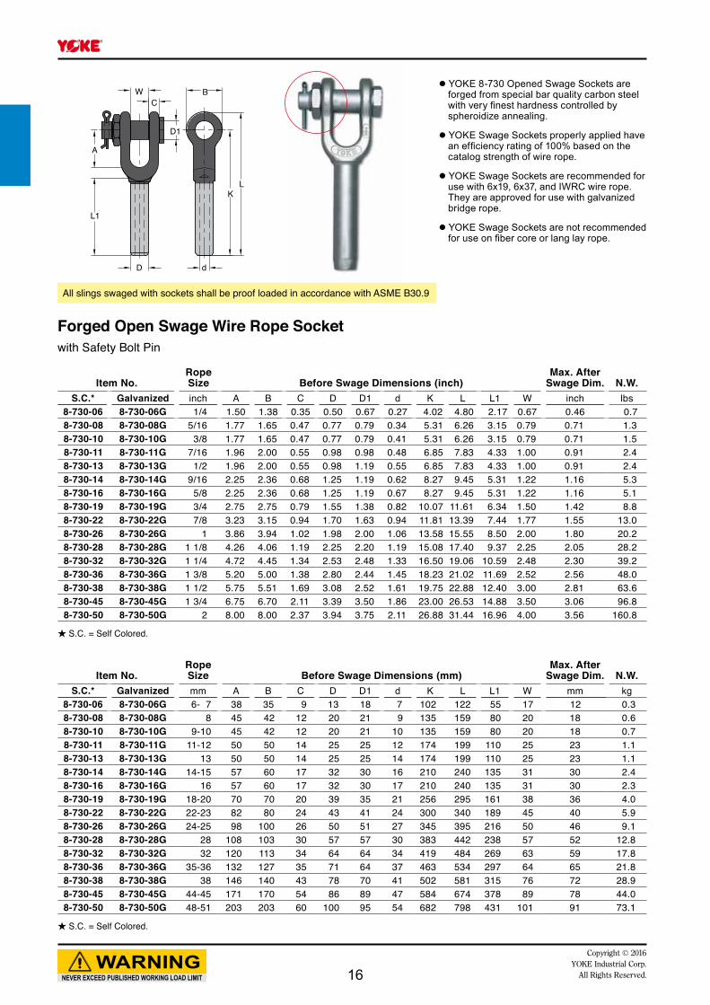
All slings swaged with sockets shall be proof loaded in accordance with ASME B30.9
Forged Open Swage Wire Rope Socketwith Safety Bolt Pin
● YOKE 8-730 Opened Swage Sockets are forged from special bar quality carbon steel with very finest hardness controlled by spheroidize annealing.
● YOKE Swage Sockets properly applied have an efficiency rating of 100% based on the catalog strength of wire rope.
● YOKE Swage Sockets are recommended for use with 6x19, 6x37, and IWRC wire rope. They are approved for use with galvanized bridge rope.
● YOKE Swage Sockets are not recommended for use on fiber core or lang lay rope.
★ S.C. = Self Colored.
★ S.C. = Self Colored.
16

D1
CW B
LK
dD
L1
A
Item No.Rope Size Before Swage Dimensions (inch)
Max. AfterSwage Dim. N.W.
S.C.* Galvanized inch A B C D D1 d K L L1 W inch lbs8-731-06 8-731-06G 1/4 1.50 1.38 0.35 0.50 0.69 0.27 4.02 4.80 2.17 0.67 0.46 0.78-731-08 8-731-08G 5/16 1.77 1.65 0.47 0.77 0.81 0.34 5.31 6.26 3.15 0.79 0.71 1.58-731-10 8-731-10G 3/8 1.77 1.65 0.47 0.77 0.81 0.41 5.31 6.26 3.15 0.79 0.71 1.38-731-11 8-731-11G 7/16 1.96 2.00 0.55 0.98 1.00 0.48 6.85 7.83 4.33 1.00 0.91 2.68-731-13 8-731-13G 1/2 1.96 2.00 0.55 0.98 1.00 0.55 6.85 7.83 4.33 1.00 0.91 2.48-731-14 8-731-14G 9/16 2.25 2.36 0.68 1.25 1.19 0.62 8.27 9.45 5.31 1.22 1.16 4.68-731-16 8-731-16G 5/8 2.25 2.36 0.68 1.25 1.19 0.67 8.27 9.45 5.31 1.22 1.16 4.68-731-19 8-731-19G 3/4 2.75 2.75 0.79 1.55 1.38 0.82 10.07 11.61 6.34 1.50 1.42 8.48-731-22 8-731-22G 7/8 3.23 3.15 0.94 1.70 1.63 0.94 11.81 13.39 7.44 1.77 1.55 11.98-731-26 8-731-26G 1 3.86 3.94 1.02 1.98 2.00 1.06 13.58 15.55 8.50 2.00 1.80 17.88-731-28 8-731-28G 1 1/8 4.26 4.06 1.19 2.25 2.20 1.19 15.08 17.40 9.37 2.25 2.05 27.58-731-32 8-731-32G 1 1/4 4.72 4.45 1.34 2.53 2.25 1.33 16.50 19.06 10.59 2.48 2.30 38.58-731-36 8-731-36G 1 3/8 5.20 5.00 1.38 2.80 2.50 1.45 18.23 21.02 11.69 2.52 2.56 468-731-38 8-731-38G 1 1/2 5.75 5.51 1.69 3.08 2.52 1.61 19.75 22.88 12.40 3.00 2.81 668-731-45 8-731-45G 1 3/4 6.75 6.70 2.11 3.39 3.50 1.86 23.00 26.53 14.88 3.50 3.06 88.78-731-50 8-731-50G 2 8.00 8.00 2.37 3.94 3.75 2.11 26.88 31.44 16.96 4.00 3.56 146.1
Item No.Rope Size Before Swage Dimensions (mm)
Max. AfterSwage Dim. N.W.
S.C.* Galvanized mm A B C D D1 d K L L1 W mm kg8-731-06 8-731-06G 6- 7 38 35 9 13 18 7 102 122 55 17 12 0.38-731-08 8-731-08G 8 45 42 12 20 21 9 135 159 80 20 18 0.78-731-10 8-731-10G 9-10 45 42 12 20 21 10 135 159 80 20 18 0.68-731-11 8-731-11G 11-12 50 50 14 25 25 12 174 199 110 25 23 1.28-731-13 8-731-13G 13 50 50 14 25 25 14 174 199 110 25 23 1.18-731-14 8-731-14G 14-15 70 60 17 32 30 16 210 240 135 31 30 2.18-731-16 8-731-16G 16 57 60 17 32 30 17 210 240 135 31 30 2.18-731-19 8-731-19G 18-20 70 70 20 39 35 21 256 295 161 38 36 3.88-731-22 8-731-22G 22-23 82 80 24 43 41 24 300 340 189 45 40 5.48-731-26 8-731-26G 24-25 98 100 26 50 51 27 345 395 216 50 46 8.18-731-28 8-731-28G 28 108 103 30 57 57 30 383 442 238 57 52 12.58-731-32 8-731-32G 32 120 113 34 64 64 34 419 484 269 63 59 17.58-731-36 8-731-36G 35-36 132 127 35 71 64 37 463 534 297 64 65 20.98-731-38 8-731-38G 38 146 140 43 78 70 41 502 581 315 76 72 30.08-731-45 8-731-45G 44-45 171 170 54 86 89 47 584 674 378 89 78 40.38-731-50 8-731-50G 48-51 203 203 60 100 95 54 682 798 431 101 91 66.4
NEVER EXCEED PUBLISHED WORKING LOAD LIMIT
WARNINGCopyright © 2016 YOKE Industrial Corp.All Rights Reserved.
● YOKE 8-731 Opened Swage Sockets are forged from special bar quality carbon steel with very finest hardness controlled by spheroidize annealing.
● YOKE Swage Sockets properly applied have an efficiency rating of 100% based on the catalog strength of wire rope.
● YOKE Swage Sockets are recommended for use with 6x19, 6x37, and IWRC wire rope. They are approved for use with galvanized bridge rope.
● YOKE Swage Sockets are not recommended for use on fiber core or lang lay rope.
All slings swaged with sockets shall be proof loaded in accordance with ASME B30.9
Forged Open Swage Socketwith Round Pin
★ S.C. = Self Colored.
★ S.C. = Self Colored.
17
H
B
LK
Dd
L1
D1
Item No.Rope Size Before Swage Dimensions (inch)
Max. AfterSwage Dim. N.W.
S.C.* Galvanized inch B D D1 d H K L L1 inch lbs8-732-06 8-732-06G 1/4 1.38 0.50 0.75 0.27 0.50 3.50 4.33 2.13 0.46 0.48-732-08 8-732-08G 5/16 1.63 0.77 0.89 0.34 0.67 4.50 5.50 3.15 0.71 0.78-732-10 8-732-10G 3/8 1.63 0.77 0.89 0.41 0.67 4.50 5.50 3.15 0.71 0.78-732-11 8-732-11G 7/16 2.00 0.98 1.06 0.48 0.89 5.75 6.93 4.25 0.91 1.58-732-13 8-732-13G 1/2 2.00 0.98 1.06 0.55 0.89 5.75 6.93 4.25 0.91 1.38-732-14 8-732-14G 9/16 2.40 1.25 1.26 0.62 1.14 7.28 8.70 5.31 1.16 3.18-732-16 8-732-16G 5/8 2.40 1.25 1.26 0.67 1.14 7.28 8.70 5.31 1.16 2.98-732-19 8-732-19G 3/4 2.87 1.55 1.44 0.82 1.31 8.54 10.20 6.38 1.42 5.18-732-22 8-732-22G 7/8 3.11 1.70 1.70 0.94 1.50 10.16 11.97 7.44 1.55 6.88-732-26 8-732-26G 1 3.62 1.98 2.05 1.06 1.77 11.54 13.46 8.50 1.80 10.68-732-28 8-732-28G 1 1/8 4.02 2.25 2.32 1.19 2.00 12.72 15.04 9.57 2.05 14.78-732-32 8-732-32G 1 1/4 4.50 2.53 2.56 1.33 2.25 14.33 16.97 10.63 2.30 21.68-732-36 8-732-36G 1 3/8 5.00 2.80 2.56 1.45 2.25 15.83 18.70 11.69 2.56 28.68-732-38 8-732-38G 1 1/2 5.50 3.08 2.81 1.61 2.52 17.01 20.12 12.75 2.81 38.18-732-45 8-732-45G 1 3/4 6.26 3.39 3.54 1.86 3.00 20.00 23.54 14.88 3.06 52.88-732-50 8-732-50G 2 7.24 3.94 3.82 2.13 3.27 23.00 27.64 17.01 3.56 89.1
Item No.Rope Size Before Swage Dimensions (mm)
Max. AfterSwage Dim. N.W.
S.C.* Galvanized mm B D D1 d H K L L1 mm kg8-732-06 8-732-06G 6- 7 35 13 19 7 13 89 110 54 12 0.28-732-08 8-732-08G 8 41 20 22 9 17 114 140 80 18 0.38-732-10 8-732-10G 9-10 41 20 22 11 17 114 140 80 18 0.38-732-11 8-732-11G 11-12 51 25 27 12 22 146 176 108 23 0.78-732-13 8-732-13G 13 51 25 27 14 22 146 176 108 23 0.68-732-14 8-732-14G 14-15 61 32 32 16 29 185 221 135 30 1.48-732-16 8-732-16G 16 61 32 32 17 29 185 221 135 30 1.38-732-19 8-732-19G 18-20 73 39 36 21 33 217 259 162 36 2.38-732-22 8-732-22G 22-23 79 43 43 24 38 258 304 189 39 3.18-732-26 8-732-26G 24-25 92 50 52 27 45 293 342 216 46 4.78-732-28 8-732-28G 28 102 57 59 30 51 323 382 243 52 6.78-732-32 8-732-32G 32 114 64 65 34 57 364 431 270 58 9.88-732-36 8-732-36G 35-36 127 71 65 37 57 402 475 297 65 13.08-732-38 8-732-38G 38 140 78 71 41 64 432 511 323 71 17.38-732-45 8-732-45G 44-45 159 86 90 47 76 508 598 378 78 24.08-732-50 8-732-50G 48-51 184 100 97 54 83 584 702 432 90 40.5
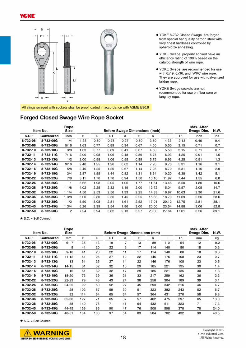
NEVER EXCEED PUBLISHED WORKING LOAD LIMIT
WARNINGCopyright © 2016
YOKE Industrial Corp.All Rights Reserved.
★ S.C. = Self Colored.
● YOKE 8-732 Closed Swage are forged from special bar quality carbon steel with very finest hardness controlled by spheroidize annealing.
● YOKE Swage properly applied have an efficiency rating of 100% based on the catalog strength of wire rope.
● YOKE Swage are recommended for use with 6x19, 6x36, and IWRC wire rope. They are approved for use with galvanized bridge rope.
● YOKE Swage sockets are not recommended for use on fiber core or lang lay rope.
All slings swaged with sockets shall be proof loaded in accordance with ASME B30.9
Forged Closed Swage Wire Rope Socket
★ S.C. = Self Colored.
18

AD1
L
dD
H
T
K
B
W
Item No. Rope Dia.Structural
Strand Dia. Dimensions (inch) N.W.S.C.* Galvanized inch inch A B D D1 d H K L T W lbs
8-735-06 8-735-06G 1/4 -- 1.50 0.50 0.71 0.88 0.43 2.25 1.73 4.50 1.50 0.50 0.78-735-10 8-735-10G 5/16 - 3/8 -- 1.69 0.62 0.83 0.98 0.50 2.25 2.00 4.88 1.70 0.71 0.98-735-13 8-735-13G 7/16 - 1/2 -- 2.00 0.71 0.98 1.19 0.55 2.52 2.25 5.43 1.96 0.87 1.58-735-16 8-735-16G 9/16 - 5/8 1/2 2.63 0.83 1.12 1.41 0.71 3.00 2.52 6.31 2.50 0.98 2.68-735-19 8-735-19G 3/4 9/16 - 5/8 3.00 1.06 1.26 1.61 0.81 3.50 3.00 7.58 2.75 1.26 4.48-735-22 8-735-22G 7/8 11/16 - 3/4 3.63 1.26 1.50 1.89 0.94 3.98 3.50 8.75 3.46 1.50 7.98-735-26 8-735-26G 1 13/16 - 7/8 4.13 1.38 1.77 2.28 1.14 4.50 4.02 9.88 3.78 1.77 10.88-735-28 8-735-28G 1 1/8 15/16 - 1 4.50 1.50 2.00 2.56 1.26 5.00 4.50 10.98 4.12 2.00 15.88-735-36 8-735-36G 1 1/4 - 1 3/8 1 1/16 - 1 1/8 5.31 1.63 2.25 2.80 1.50 5.50 5.00 12.31 4.75 2.25 23.18-735-38 8-735-38G 1 1/2 1 3/16 - 1 1/4 5.31 1.93 2.75 3.19 1.63 6.00 6.00 13.94 5.25 2.52 31.5
Item No. Rope Dia.Structural
Strand Dia. Dimensions (mm) N.W.S.C.* Galvanized mm mm A B D D1 d H K L T W kg
8-735-06 8-735-06G 6- 7 -- 38 13 18 22 11 57 44 114 38 13 0.38-735-10 8-735-10G 8-10 -- 43 16 21 25 13 57 51 124 43 18 0.48-735-13 8-735-13G 11-13 -- 51 18 25 30 14 64 57 138 50 22 0.78-735-16 8-735-16G 14-16 13 67 21 28 36 18 76 64 160 63 25 1.28-735-19 8-735-19G 18-20 14-16 76 27 32 41 21 89 76 192 70 32 2.08-735-22 8-735-22G 22-23 18-20 92 32 38 48 24 101 89 222 88 38 3.68-735-26 8-735-26G 24-26 22-23 104 35 45 58 29 114 102 251 96 45 4.98-735-28 8-735-28G 28-30 24-25 114 38 51 65 32 127 114 279 105 50 7.28-735-36 8-735-36G 32-35 26-28 135 41 57 71 38 140 127 308 121 57 10.58-735-38 8-735-38G 36-39 30-32 135 49 70 81 41 152 152 354 133 64 14.3
NEVER EXCEED PUBLISHED WORKING LOAD LIMIT
WARNINGCopyright © 2016 YOKE Industrial Corp.All Rights Reserved.
● YOKE Spelter are forged from special bar quality carbon steel with very finest hardness controlled.
● YOKE Spelter properly applied have an efficiency rating of 100% based on the catalog strength of wire rope.
● Socket size 1/4" thru 3/4" use one groove, 7/8" thru 1-1/2" use 2 grooves.
● Closed Spelter sockets meet the performance requirements of Federal Specification RR-S-550E,Type B.
In accordance with ASME B30.9 all assembly slings with poured spelter , shall be proof loaded.
Forged Closed Spelter Wire Rope Socket
★ S.C. = Self Colored.
★ S.C. = Self Colored.
19

C W
D1
K
A
L
H
d
DT
Item No. Rope Dia.Structural
Strand Dia. Dimensions (inch) N.W.S.C.* Galvanized inch inch A C D D1 d H K L T W lbs
8-734-06 8-734-06G 1/4 -- 1.31 0.35 0.71 0.67 0.43 2.25 1.56 4.65 1.54 0.91 1.18-734-10 8-734-10G 5/16 - 3/8 -- 1.50 0.44 0.83 0.79 0.51 2.25 1.77 4.84 1.73 0.83 1.38-734-13 8-734-13G 7/16 - 1/2 -- 1.91 0.50 0.98 0.98 0.56 2.48 2.13 5.62 1.96 1.00 2.48-734-16 8-734-16G 9/16 - 5/8 1/2 2.28 0.55 1.14 1.19 0.70 3.00 2.52 6.77 2.25 1.26 4.08-734-19 8-734-19G 3/4 9/16 - 5/8 2.64 0.62 1.26 1.38 0.81 3.62 3.00 7.96 2.64 1.50 5.78-734-22 8-734-22G 7/8 11/16 - 3/4 3.17 0.80 1.50 1.63 0.94 4.02 3.50 9.25 3.35 1.77 10.38-734-26 8-734-26G 1 13/16 - 7/8 3.78 0.91 1.75 2.00 1.14 4.48 4.02 10.55 3.75 2.05 16.38-734-28 8-734-28G 1 1/8 15/16 - 1 4.12 1.00 2.00 2.25 1.26 5.00 4.62 11.81 4.12 2.25 22.28-734-36 8-734-36G 1 1/4 - 1 3/8 1 1/16 - 1 1/8 4.75 1.14 2.25 2.50 1.50 5.51 5.00 13.20 4.72 2.52 32.88-734-38 8-734-38G 1 1/2 1 3/16 - 1 1/4 5.38 1.19 2.75 2.75 1.63 6.00 6.00 15.12 5.25 3.00 45.5
Item No. Rope Dia.Structural
Strand Dia. Dimensions (mm) N.W.S.C.* Galvanized mm mm A C D D1 d H K L T W kg
8-734-06 8-734-06G 6 - 7 -- 33 9 18 17 11 57 40 115 39 23 0.58-734-10 8-734-10G 8 - 10 -- 38 11 21 20 13 57 45 123 44 21 0.68-734-13 8-734-13G 11 - 13 -- 48 13 25 25 15 63 54 142 50 25 1.18-734-16 8-734-16G 14 - 16 13 58 14 29 30 18 76 64 172 57 32 1.88-734-19 8-734-19G 18 - 20 14 - 16 67 16 32 35 22 92 76 202 67 38 2.68-734-22 8-734-22G 22 - 23 18 - 20 80 20 38 41 24 102 89 235 85 45 4.78-734-26 8-734-26G 24 - 26 22 - 23 96 23 44 51 29 114 102 268 95 52 7.48-734-28 8-734-28G 28 - 30 24 - 25 105 25 51 56 32 127 117 300 105 57 10.18-734-36 8-734-36G 32 - 35 26 - 28 121 29 57 62 38 140 127 335 120 64 14.98-734-38 8-734-38G 36 - 39 30 - 32 137 30 70 70 41 152 152 384 133 76 20.7
NEVER EXCEED PUBLISHED WORKING LOAD LIMIT
WARNINGCopyright © 2016
YOKE Industrial Corp.All Rights Reserved.
● YOKE Spelter Sockets are forged from special bar quality carbon steel with very finest hardness controlled.
● YOKE Spelter Sockets properly applied have an efficiency rating of 100% based on the catalog strength of wire rope.
● Socket size 1/4" thru 3/4" use one groove, 7/8" thru 1-1/2" use 2 grooves.
● Open Spelter sockets meet the performance requirements of Federal Specification RR-S-550D,Type A.
In accordance with ASME B30.9 all assembly slings with poured Spelter , shall be proof loaded.
Forged Open Spelter Wire Rope Socketwith Round Pin
★ S.C. = Self Colored.
★ S.C. = Self Colored.
20

A
K
H
T
L
D1
WC
d
D
Item No. Rope Dia.Structural
Strand Dia. Dimensions (inch) N.W.S.C.* Galvanized inch inch A C D D1 d H K L T W lbs
8-733-06 8-733-06G 1/4 -- 1.31 0.35 0.71 0.67 0.43 2.25 1.56 4.65 1.54 0.91 1.58-733-10 8-733-10G 5/16 - 3/8 -- 1.50 0.44 0.83 0.79 0.51 2.25 1.77 4.84 1.73 0.83 2.08-733-13 8-733-13G 7/16 - 1/2 -- 1.91 0.50 0.98 0.98 0.56 2.48 2.13 5.62 1.96 1.00 3.58-733-16 8-733-16G 9/16 - 5/8 1/2 2.28 0.55 1.14 1.19 0.70 2.99 2.52 6.77 2.25 1.26 4.98-733-19 8-733-19G 3/4 9/16 - 5/8 2.64 0.62 1.26 1.38 0.81 3.62 3.00 7.96 2.64 1.50 7.58-733-22 8-733-22G 7/8 11/16 - 3/4 3.17 0.80 1.50 1.63 0.94 4.02 3.50 9.25 3.35 1.77 11.98-733-26 8-733-26G 1 13/16 - 7/8 3.78 0.91 1.75 2.00 1.14 4.48 4.02 10.55 3.75 2.05 18.78-733-28 8-733-28G 1 1/8 15/16 - 1 4.12 1.00 2.00 2.25 1.26 5.00 4.62 11.81 4.12 2.25 25.68-733-36 8-733-36G 1 1/4 - 1 3/8 1 1/16 - 1 1/8 4.75 1.14 2.25 2.50 1.50 5.51 5.00 13.20 4.72 2.52 35.28-733-38 8-733-38G 1 1/2 1 3/16 - 1 1/4 5.38 1.19 2.75 2.75 1.63 5.98 5.98 15.12 5.25 2.99 52.9
Item No. Rope Dia.Structural
Strand Dia. Dimensions (mm) N.W.S.C.* Galvanized mm mm A C D D1 d H K L T W kg
8-733-06 8-733-06G 6 - 7 -- 33 9 18 17 11 57 40 115 39 23 0.78-733-10 8-733-10G 8 - 10 -- 38 11 21 20 13 57 45 123 44 21 0.98-733-13 8-733-13G 11 - 13 -- 48 13 25 25 15 63 54 142 50 25 1.68-733-16 8-733-16G 14 - 16 13 58 14 29 30 18 76 64 172 57 32 2.28-733-19 8-733-19G 18 - 20 14 - 16 67 16 32 35 22 92 76 202 67 38 3.48-733-22 8-733-22G 22 - 23 18 - 20 80 20 38 41 24 102 89 235 85 45 5.48-733-26 8-733-26G 24 - 26 22 - 23 96 23 44 51 29 114 102 268 95 52 8.58-733-28 8-733-28G 28 - 30 24 - 25 105 25 51 56 32 127 117 300 105 57 11.68-733-36 8-733-36G 32 - 35 26 - 28 121 29 57 62 38 140 127 335 120 64 16.08-733-38 8-733-38G 36 - 39 30 - 32 137 30 70 70 41 152 152 384 133 76 24.0
NEVER EXCEED PUBLISHED WORKING LOAD LIMIT
WARNINGCopyright © 2016 YOKE Industrial Corp.All Rights Reserved.
★ S.C. = Self Colored.
★ S.C. = Self Colored.
● YOKE Spelter Sockets are forged from special bar quality carbon steel with very finest hardness controlled.
● YOKE Spelter Sockets properly applied have an efficiency rating of 100% based on the catalog strength of wire rope.
● Socket size 1/4" thru 3/4" use one groove, 7/8" thru 1-1/2" use 2 grooves.
● Open Spelter sockets meet the performance requirements of Federal Specification RR-S-550D,Type A.
In accordance with ASME B30.9 all assembly slings with poured Spelter , shall be proof loaded.
Forged Open Spelter Wire Rope Socketwith Safety Bolt Pin
21

R
DE
L
H
T
C
PP1
G
Item No.Rope Size Hook
Feature code
WorkingLoad Limit Dimensions (inch)
Max.After Swage Dim. N.W.
with latch without latch inch tonnes* C D E G H L P P1 R T inch lbs8-739.SC-0075 8-739.SC/0-0075 3/6 AA 0.4 0.97 0.70 0.44 3.07 0.75 5.32 1.02 0.95 2.00 0.63 0.40 0.78-739.SC-01 8-739.SC/0-01 1/4 BB 0.7 0.97 0.90 0.50 3.15 0.87 5.75 1.06 1.00 2.30 0.71 0.46 0.98-739.SC-015 8-739.SC/0-015 5/16 CC 1.1 1.03 1.02 0.67 3.58 1.00 6.46 1.14 1.06 2.60 0.88 0.58 1.38-739.SC-02 8-739.SC/0-02 5/16 DD 1.1 1.03 1.14 0.77 4.02 1.18 7.28 1.22 1.18 2.80 0.94 0.71 1.88-739.SC-02D 8-739.SC/0-02D 3/8 DD 1.6 1.16 1.14 0.77 4.02 1.18 7.28 1.22 1.18 2.80 0.94 0.71 1.88-739.SC-03 8-739.SC/0-03 7/16 EE 2.1 1.53 1.18 0.98 5.12 1.46 8.89 1.61 1.42 3.40 1.31 0.91 3.78-739.SC-03D 8-739.SC/0-03D 1/2 EE 2.8 1.53 1.18 0.98 5.12 1.46 8.89 1.61 1.42 3.40 1.31 0.91 3.58-739.SC-05 8-739.SC/0-05 9/16 FF 3.5 1.94 1.49 1.25 6.54 1.82 10.98 2.13 1.69 3.80 1.66 1.16 7.58-739.SC-05D 8-739.SC/0-05D 5/8 FF 4.3 1.94 1.49 1.25 6.54 1.82 10.98 2.13 1.69 3.80 1.66 1.16 7.38-739.SC-075 8-739.SC/0-075 3/4 GG 6.2 2.46 1.77 1.53 7.72 2.28 12.91 2.40 2.24 5.00 1.88 1.42 12.88-739.SC-10 8-739.SC/0-10 7/8 HH 8.3 2.59 2.00 1.70 8.70 2.60 13.54 2.83 2.44 5.00 2.19 1.55 18.78-739.SC-15 8-739.SC/0-15 1 JJ 11.0 2.81 2.63 1.98 10.91 3.01 16.97 3.39 3.19 5.80 2.69 1.80 34.18-739.SC-20 8-739.SC/0-20 1 1/8 KK 14.0 3.44 2.75 2.25 13.90 3.62 23.07 3.50 3.27 10.00 3.00 2.05 66.4
Item No.Rope Size Hook
Feature code
WorkingLoad Limit Dimensions (mm)
Max.After Swage Dim. N.W.
with latch without latch mm tonnes* C D E G H L P P1 R T mm kg8-739.SC-0075 8-739.SC/0-0075 5 AA 0.4 25 18 11 78 19 135 26 24 51 16 10 0.38-739.SC-01 8-739.SC/0-01 6- 7 BB 0.7 25 23 13 80 22 146 27 25 58 18 12 0.48-739.SC-015 8-739.SC/0-015 8 CC 1.1 26 26 17 91 25 164 29 27 66 22 15 0.68-739.SC-02 8-739.SC/0-02 8 DD 1.1 29 29 20 102 30 185 31 30 71 24 18 0.88-739.SC-02D 8-739.SC/0-02D 9-10 DD 1.6 29 29 20 102 30 185 31 30 71 24 18 0.88-739.SC-03 8-739.SC/0-03 11-12 EE 2.1 38 30 25 130 38 226 41 36 86 33 23 1.78-739.SC-03D 8-739.SC/0-03D 13 EE 2.8 38 30 25 130 38 226 41 36 86 33 23 1.68-739.SC-05 8-739.SC/0-05 14-15 FF 3.5 49 38 32 166 46 279 54 43 97 42 30 3.48-739.SC-05D 8-739.SC/0-05D 16 FF 4.3 49 38 32 166 46 279 54 43 97 42 30 3.38-739.SC-075 8-739.SC/0-075 18-20 GG 6.2 62 45 39 196 58 328 61 57 127 48 36 5.88-739.SC-10 8-739.SC/0-10 22-23 HH 8.3 65 51 43 221 66 344 72 62 127 56 39 8.58-739.SC-15 8-739.SC/0-15 24-25 JJ 11.0 71 67 50 277 77 431 86 81 147 68 46 15.58-739.SC-20 8-739.SC/0-20 28 KK 14.0 87 70 57 353 92 586 89 83 254 76 52 30.2
NEVER EXCEED PUBLISHED WORKING LOAD LIMIT
WARNINGCopyright © 2016
YOKE Industrial Corp.All Rights Reserved.
● YOKE Swaging Hoist Hooks are forged from special bar quality carbon steel with very special Quenched and Tempered.
● YOKE Swaging Hoist Hooks properly applied have an efficiency rating of 95% based on the catalog strength of wire rope.
● YOKE Swaging Hoist Hooks are recommended for use with 6 x 19 or 6 x 37, IPS or XIP, FC or IWRC wire rope.
● YOKE Swaging Hoist Hooks are not recommended for use on fiber core or lang lay rope.
All slings swaged with shall be proof loaded in accordance with ANSI B30.9
Swaging Hoist Hook
★ S.C. = Self Colored.
★ S.C. = Self Colored.
22
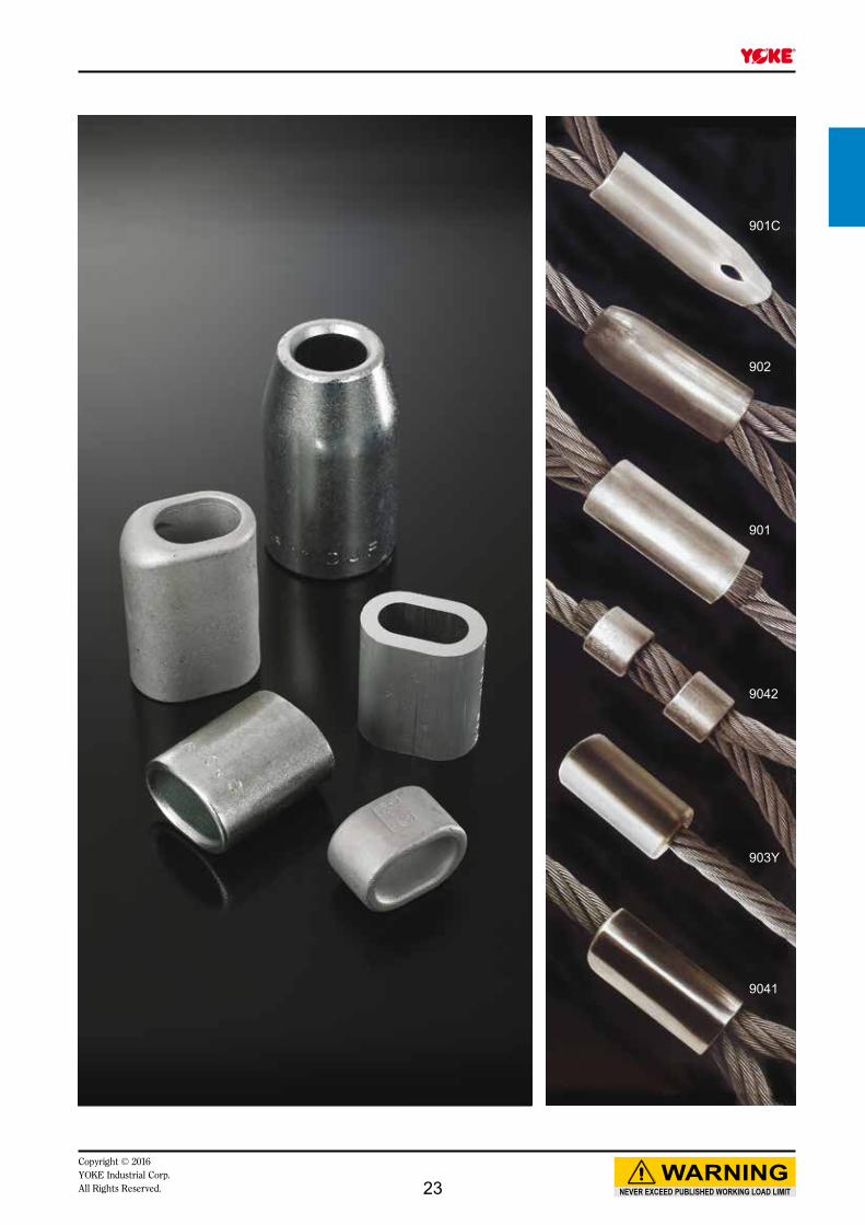
901C
901
903Y
902
9042
9041
NEVER EXCEED PUBLISHED WORKING LOAD LIMIT
WARNINGCopyright © 2016 YOKE Industrial Corp.All Rights Reserved. 23
A
D
B
E
G
A
B
L
T
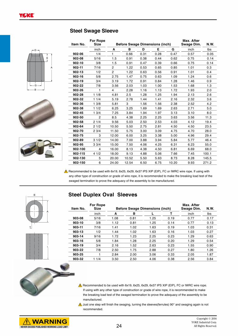
Item No.For Rope
Size Before Swage Dimensions (inch)Max. After
Swage Dim. N.W.inch A B D E G inch lbs
902-06 1/4 1 0.66 0.31 0.28 0.47 0.57 0.05902-08 5/16 1.5 0.91 0.38 0.44 0.62 0.75 0.14902-10 3/8 1.5 0.91 0.47 0.39 0.66 0.75 0.14902-11 7/16 2 1.22 0.53 0.65 0.85 1.01 0.3902-13 1/2 2 1.22 0.63 0.56 0.91 1.01 0.4902-16 5/8 2.75 1.47 0.75 0.63 1.09 1.24 0.6902-19 3/4 3.19 1.72 0.91 0.84 1.28 1.46 0.9902-22 7/8 3.56 2.03 1.03 1.00 1.53 1.68 1.3902-26 1 4 2.28 1.16 1.13 1.72 1.93 2.0902-28 1 1/8 4.81 2.5 1.28 1.25 1.94 2.13 2.6902-32 1 1/4 5.19 2.78 1.44 1.41 2.16 2.32 3.6902-36 1 3/8 5.81 3 1.56 1.56 2.38 2.52 4.2902-38 1 1/2 6.25 3.25 1.69 1.69 2.63 2.71 5.0902-45 1 3/4 7.25 3.84 1.94 1.97 3.13 3.10 8.0902-50 2 8.5 4.38 2.25 2.25 3.63 3.56 11.3902-58 2 1/4 9.56 5.03 2.50 2.53 4.03 4.12 19.4902-64 2 1/2 10.50 5.50 2.75 2.81 4.50 4.50 23.5902-70 2 3/4 11.50 5.75 3.00 3.09 4.75 4.70 28.0902-75 3 12.00 6.00 3.25 3.38 5.00 4.96 29.4902-89 3 1/2 14.00 7.00 3.88 3.94 5.84 5.77 46.4902-95 3 3/4 15.00 7.50 4.06 4.25 6.31 6.23 55.0902-100 4 16.00 8.13 4.38 4.50 6.81 6.69 68.0902-115 4 1/2 18.00 9.13 4.88 5.06 7.66 7.45 100.1902-130 5 20.00 10.52 5.50 5.63 8.73 8.28 145.5902-150 6 24.00 12.54 6.50 6.75 10.20 9.93 271.2
Item No.For Rope
Size Before Swage Dimensions (inch)Max. After
Swage Dim. N.W.inch A B L T inch lbs
903-08 5/16 1.08 0.81 1.25 0.19 0.77 0.17903-10 3/8 1.12 0.81 1.25 0.14 0.77 0.13903-11 7/16 1.41 1.02 1.63 0.19 1.03 0.31903-13 1/2 1.44 1.02 1.63 0.16 1.03 0.27903-14 9/16 1.72 1.23 2.25 0.23 1.29 0.63903-16 5/8 1.84 1.28 2.25 0.20 1.29 0.54903-19 3/4 2.16 1.52 2.63 0.23 1.55 0.90903-22 7/8 2.50 1.75 2.88 0.27 1.80 1.26903-25 1 2.84 2.00 3.06 0.33 2.05 1.87903-32 1 1/4 3.50 2.50 4.06 0.38 2.56 3.84
NEVER EXCEED PUBLISHED WORKING LOAD LIMIT
WARNINGCopyright © 2016
YOKE Industrial Corp.All Rights Reserved.
Steel Swage Sleeve
Recommended to be used with 6x19, 6x25, 6x29, 6x37 IPS XIP (EIP), FC or IWRC wire rope. If using with any other type of construction or grade of wire rope, it is recommended to make the breaking load test of the swaged termination to prove the adequacy of the assembly to be manufactured.
Recommended to be used with 6x19, 6x25, 6x29, 6x37 IPS XIP (EIP), FC or IWRC wire rope. If using with any other type of construction or grade of wire rope, it is recommended to make the breaking load test of the swaged termination to prove the adequacy of the assembly to be manufactured.Just one step will finish the swaging, turning the sleeves(ferrules) 90° and swaging again is not recommended.
Steel Duplex Oval Sleeves
24

D
B
L
A
B
L
A
B
L
B D L903Y-03 1/8 0.44 0.14 0.50 0.40 0.02903Y-05 3/16 0.56 0.20 0.70 0.52 0.04903Y-06 1/4 0.63 0.30 1.06 0.58 0.08903Y-08 5/16 0.88 0.36 1.13 0.77 0.16903Y-10 3/8 0.88 0.42 1.48 0.77 0.15903Y-11 7/16 1.13 0.48 1.63 1.03 0.30903Y-13 1/2 1.31 0.55 1.89 1.16 0.50903Y-14 9/16 1.44 0.61 2.02 1.29 0.70903Y-16 5/8 1.56 0.67 2.42 1.42 1.00903Y-19 3/4 1.69 0.79 2.73 1.55 1.31903Y-22 7/8 2.00 0.94 3.27 1.80 2.20903Y-25 1 2.25 1.06 3.67 2.05 3.10903Y-28 1 1/8 2.56 1.19 4.05 2.30 4.50903Y-32 1 1/4 2.81 1.33 4.58 2.56 6.51
A B L9041-06 1/4 3/4 9/16 7/8 0.53 0.03 9041-08 5/16 1 1/8 25/32 1 19/32 0.76 0.18 9041-10 3/8 1 1/8 13/16 1 23/32 0.76 0.14 9041-11 7/16 1 7/16 1 1/32 2 1/32 1.01 0.35 9041-13 1/2 1 7/16 1 2 1.01 0.31 9041-14 9/16 1 3/4 1 3/16 2 1/4 1.27 0.60 9041-16 5/8 1 13/16 1 1/4 2 3/8 1.27 0.60 9041-19 3/4 2 1/8 1 7/16 3 1/16 1.53 1.00 9041-22 7/8 2 1/2 3 3/8 3 1/4 1.76 1.50 9041-25 1 2 7/8 3 7/8 3 3/4 2.04 2.00
A B L9042-13 1/2 1 3/8 15/16 1 1/16 1.01 0.20 9042-14 9/16 1 11/16 1 3/16 1 1/4 1.27 0.31 9042-16 5/8 1 13/16 1 13/16 1 1/16 1.27 0.30 9042-19 3/4 2 1/8 1 3/8 1 3/16 1.53 0.50 9042-22 7/8 2 1/2 1 4/3 1 3/8 1.76 0.70 9042-25 1 2 3/4 1 13/16 1 9/16 2.04 1.00 9042-28 1 1/8 3 3/16 2 1 7/8 2.26 1.50 9042-32 1 1/4 3 3/8 2 3/8 2 1/8 2.51 2.00 9042-35 1 3/8 3 9/16 2 5/16 2 1/8 2.51 2.00 9042-38 1 1/2 3 7/8 2 1/2 2 1/4 2.70 2.00 9042-42 1 5/8 4 5/16 2 13/16 2 3/8 3.08 3.00 9042-45 1 3/4 4 7/16 2 13/16 2 1/2 3.08 3.30 9042-50 2 5 3 3/16 2 7/8 3.52 4.30 9042-57 2 1/4 5 11/16 3 3/4 3 1/8 4.02 6.51 9042-64 2 1/2 6 3/8 4 3 1/8 4.39 7.51
NEVER EXCEED PUBLISHED WORKING LOAD LIMIT
WARNINGCopyright © 2016 YOKE Industrial Corp.All Rights Reserved.
Steel Swage Buttons
Stainless Steel One-Piece Sleeves
Stainless Steel Two-Piece Sleeves
Recommended to be used with 6x19, 6x25, 6x29, 6x37 IPS XIP (EIP), FC or IWRC wire rope. If using with any other type of construction or grade of wire rope, it is recommended to make the breaking load test of the swaged termination to prove the adequacy of the assembly to be manufactured.
Recommended to be used with 6x19, 6x25, 6x29, 6x37 IPS XIP (EIP), FC or IWRC wire rope. If using with any other type of construction or grade of wire rope, it is recommended to make the breaking load test of the swaged termination to prove the adequacy of the assembly to be manufactured.Just one step will finish the swaging, turning the sleeves(ferrules) 90° and swaging again is not recommended.
Recommended to be used with 6x19, 6x25, 6x29, 6x37 IPS XIP (EIP), FC or IWRC wire rope. If using with any other type of construction or grade of wire rope, it is recommended to make the breaking load test of the swaged termination to prove the adequacy of the assembly to be manufactured.Just one step will finish the swaging, turning the sleeves(ferrules) 90° and swaging again is not recommended.
Item No.For Rope
Size Before Swage Dimensions (inch)Max. After
Swage Dim. N.W.inch inch lbs
Item No.For Rope
Size Before Swage Dimensions (inch)Max. After
Swage Dim. N.W.inch inch lbs
Item No.For Rope
Size Before Swage Dimensions (inch)Max. After
Swage Dim. N.W.inch inch lbs
25

A
T
L
B
Item No.For Rope
Size Before Swage Dimensions (mm)Max. After
Swage Dim. N.W.
(PER 1000 PC)mm A B L T mm kg
901-001 1 1.20 2.40 5 0.65 2 0.094901-001P5 1.5 1.70 3.40 6 0.75 3 0.211901-002 2 2.20 4.40 7 0.85 4 0.375901-002P5 2.5 2.70 5.40 9 1.05 5 0.499901-003 3 3.30 6.60 11 1.25 6 0.843901-003P5 3.5 3.80 7.60 13 1.50 7 1.32901-004 4 4.40 8.80 14 1.70 8 1.81901-004P5 4.5 4.90 9.80 16 1.90 9 2.61901-005 5 5.50 11.00 18 2.10 10 3.57901-006 6 6.60 13.20 21 2.50 12 5.86901-006P5 6.5 7.20 14.40 23 2.70 13 7.55901-007 7 7.80 15.60 25 2.90 14 9.50901-008 8 8.80 17.60 28 3.30 16 13.70901-009 9 9.90 19.80 32 3.70 18 19.80901-010 10 10.90 21.80 35 4.10 20 26.40901-011 11 12.10 24.20 39 4.50 22 35.80901-012 12 13.20 26.40 42 4.90 24 45.80901-013 13 14.20 28.40 46 5.40 26 59.70901-014 14 15.30 30.60 49 5.80 28 73.50901-016 16 17.50 35.00 56 6.70 32 111901-018 18 19.60 39.20 63 7.60 36 156901-020 20 21.70 43.40 70 8.40 40 217901-022 22 24.30 48.60 77 9.20 44 292901-024 24 26.40 52.80 84 10.00 48 376901-026 26 28.50 57.00 91 10.90 52 481901-028 28 31.00 62.00 98 11.70 56 603901-030 30 33.10 66.20 105 12.50 60 739901-032 32 35.20 70.40 112 13.40 64 897901-034 34 37.80 75.60 119 14.20 68 1077901-036 36 39.80 79.60 126 15.00 72 1275901-038 38 41.90 83.80 133 15.80 76 1503901-040 40 44.00 88.00 140 16.60 80 1734901-042 42 46.20 92.40 147 17.50 84 2024901-044 44 48.40 96.80 154 18.30 88 2314901-046 46 50.60 101.20 161 19.20 92 2662901-048 48 52.80 105.60 168 20.00 96 3010901-050 50 55.00 110.00 175 20.80 100 3412901-052 52 57.20 114.40 182 21.60 104 3813901-054 54 59.40 118.80 189 22.50 108 4293901-056 56 61.60 123.20 196 23.30 112 4772901-058 58 63.80 127.60 203 24.20 116 5326901-060 60 66.00 132.00 210 25.00 120 5880
NEVER EXCEED PUBLISHED WORKING LOAD LIMIT
WARNINGCopyright © 2016
YOKE Industrial Corp.All Rights Reserved.
Aluminum FerrulesSpec. acc. to EN13411-3 (DIN 3093)
※ Sizes not mentioned in the EN13411-3 (DIN3093) and others up to #104 are all available.
Just one step will finish the swaging, turning the sleeves(ferrules) 90° and swaging again is not recommended.
26

Copyright © 2016YOKE Industrial Corp.All Rights Reserved. 27
D
W
H
E
A
B
G
Item No.Nominal
SizeWorking
Load Limit Dimensions (inch) N.W.inch tonnes* A B D E G H W lbs
8-808-08 5/16 1.2 1.22 0.31 0.37 0.82 0.75 2.13 0.47 0.28-808-10 3/8 2 1.42 0.39 0.43 1.02 0.91 2.56 0.63 0.28-808-11 7/16 2.7 1.70 0.43 0.51 1.18 1.06 2.95 0.75 0.48-808-13 1/2 3.3 1.85 0.52 0.63 1.30 1.18 3.34 0.79 0.78-808-16 5/8 5 2.40 0.63 0.75 1.77 1.53 4.21 1.06 1.58-808-19 3/4 7 2.83 0.75 0.87 1.97 1.81 5.04 1.30 2.28-808-22 7/8 9.5 3.39 0.87 1.02 2.28 2.09 5.91 1.50 3.78-808-26 1 12.5 3.78 1.02 1.10 2.68 2.36 6.57 1.73 5.38-808-28 1 1/8 15 4.37 1.10 1.26 2.91 2.68 7.52 1.81 7.58-808-32 1 1/4 18 4.76 1.26 1.42 3.22 2.99 8.07 2.12 10.68-808-36 1 3/8 21 5.28 1.42 1.50 3.62 3.31 9.13 2.32 14.38-808-38 1 1/2 30 5.57 1.50 1.77 3.90 3.62 10.00 2.36 19.18-808-45 1 3/4 40 7.00 1.85 2.00 5.00 4.17 12.32 2.87 38.58-808-50 2 55 7.76 2.09 2.24 5.75 4.80 13.66 3.27 53.2
Item No.Nominal
SizeWorking
Load Limit Dimensions (mm) N.W.mm tonnes* A B D E G H W kg
8-808-08 8 1.2 31 8 9.5 21 19 54 13 0.18-808-10 10 2 36 10 11 26 23 65 16 0.18-808-11 11 2.7 43 11 13 30 27 75 19 0.28-808-13 13 3.3 47 13 16 33 30 85 20 0.38-808-16 16 5 61 16 19 43 39 107 27 0.78-808-19 19 7 72 19 22 50 46 126 33 1.08-808-22 22 9.5 86 22 26 58 53 148 38 1.78-808-26 26 12.5 96 26 28 68 60 166 44 2.48-808-28 28 15 111 28 32 74 68 190 46 3.48-808-32 32 18 121 32 36 82 76 210 54 4.88-808-36 36 21 134 36 38 92 84 232 59 6.58-808-38 38 30 146 38 45 99 92 254 60 8.78-808-45 45 40 178 47 51 127 106 313 73 17.58-808-50 50 55 197 53 57 146 122 347 83 24.2
NEVER EXCEED PUBLISHED WORKING LOAD LIMIT
WARNINGCopyright © 2016
YOKE Industrial Corp.All Rights Reserved.
YOKE 8-808 Bolt Type Anchor Shackles meet the performance requirements of Federal Specification RR-C-271F, Type 4A , Grade B, Class 3.
Forged Alloy Anchor Shacklewith Bolt Pin
★ Minimum Ultimate Load is 5 times the Working Load Limit. Maximun Proof Load is 2 times the Working Load Limit.
● Shackles are Type Approved by DNV & ABS.
● Shackles are forged alloy steel with alloy pin.
● Size and the Working Load Limit permanently shown on each shackle.
● All shackles with Batch Code which links to Test Certificate and quality traceability.
● 100% magnaflux crack detection during manufacturing.
● 20,000 cycle fatigue rated to 1.5 times Working Load Limit.
Type Approval
28

D
A
E
H
W
B
G
Item No.Nominal
SizeWorking
Load Limit Dimensions (inch) N.W.inch tonnes* A B D E G H W lbs
8-807-08 5/16 1.2 1.22 0.31 0.37 0.83 0.75 2.13 0.47 0.28-807-10 3/8 2 1.42 0.39 0.43 1.02 0.91 2.56 0.63 0.28-807-11 7/16 2.7 1.70 0.43 0.51 1.18 1.06 2.95 0.75 0.48-807-13 1/2 3.3 1.85 0.52 0.63 1.30 1.18 3.34 0.79 0.78-807-16 5/8 5 2.40 0.63 0.75 1.77 1.53 4.21 1.06 1.38-807-19 3/4 7 2.83 0.75 0.87 1.97 1.81 4.96 1.30 2.28-807-22 7/8 9.5 3.39 0.87 1.02 2.28 2.09 5.82 1.50 3.38-807-26 1 12.5 3.78 1.02 1.10 2.68 2.36 6.53 1.73 5.18-807-28 1 1/8 15 4.37 1.10 1.26 2.91 2.68 7.48 1.81 7.08-807-32 1 1/4 18 4.76 1.26 1.42 3.22 2.99 8.26 2.12 9.78-807-36 1 3/8 21 5.28 1.42 1.50 3.62 3.31 9.13 2.32 13.2
Item No.Nominal
SizeWorking
Load Limit Dimensions (mm) N.W.mm tonnes* A B D E G H W kg
8-807-08 8 1.2 31 8 9.5 21 19 54 12 0.1 8-807-10 10 2 36 10 11 26 23 65 16 0.18-807-11 11 2.7 43 11 13 30 27 75 19 0.28-807-13 13 3.3 47 13 16 33 30 85 20 0.38-807-16 16 5 61 16 19 43 39 107 27 0.68-807-19 19 7 72 19 22 50 46 126 33 1.08-807-22 22 9.5 86 22 26 58 53 148 38 1.58-807-26 26 12.5 96 26 28 68 60 166 44 2.38-807-28 28 15 111 28 32 74 68 190 46 3.28-807-32 32 18 121 32 36 84 76 210 54 4.48-807-36 36 21 134 36 38 92 84 232 59 6.0
NEVER EXCEED PUBLISHED WORKING LOAD LIMIT
WARNINGCopyright © 2016 YOKE Industrial Corp.All Rights Reserved.
★ Minimum Ultimate Load is 5 times the Working Load Limit. Maximun Proof Load is 2 times the Working Load Limit.
Type Approval YOKE 8-807 Screw Pin Anchor Shackles meet the performance requirements of Federal Specification RR-C-271F, Type 4A , Grade B, Class 2.
Forged Alloy Anchor shacklewith Screw Pin
● Shackles are Type Approved by DNV & ABS.
● Shackles are forged alloy steel with alloy pin.
● Size and the Working Load Limit permanently shown on each shackle.
● All shackles with Batch Code which links to Test Certificate and quality traceability.
● 100% magnaflux crack detection during manufacturing.
● 20,000 cycle fatigue rated to 1.5 times Working Load Limit.
29
E
H
W
D
A
B
G
Item No.Nominal
SizeWorking
Load Limit Dimensions (inch) N.W.inch tonnes* A B D E G H W lbs
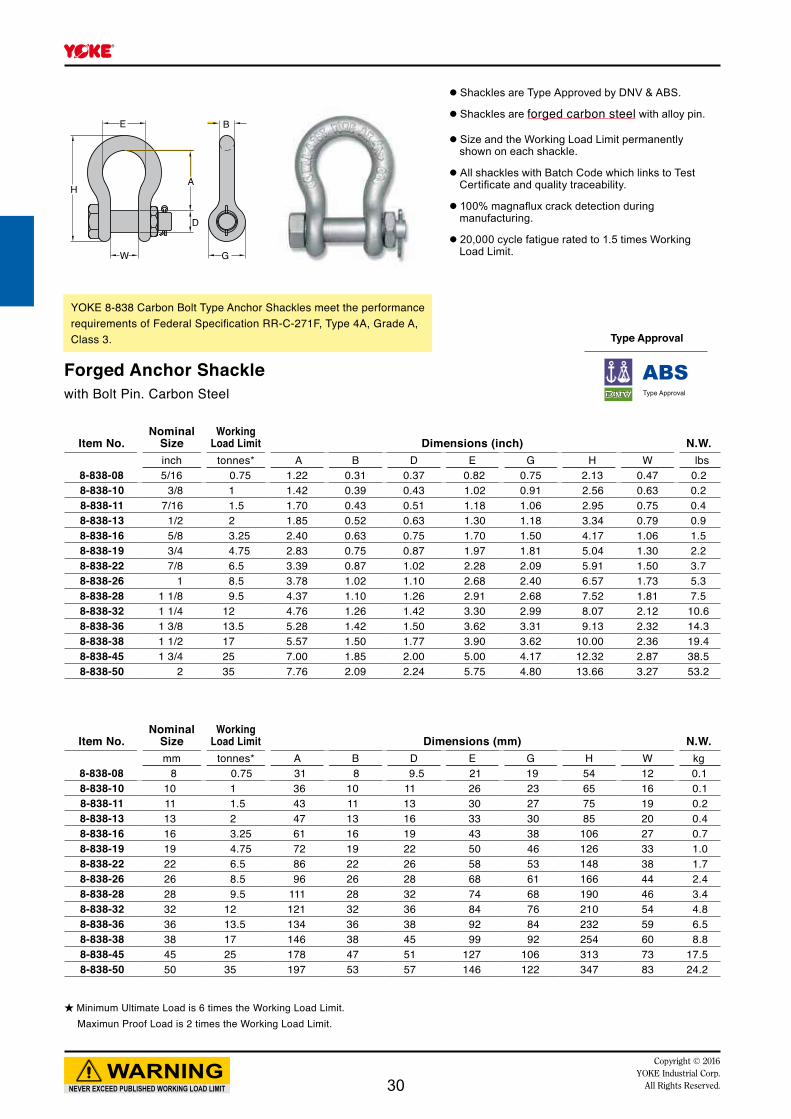
8-838-08 5/16 0.75 1.22 0.31 0.37 0.82 0.75 2.13 0.47 0.28-838-10 3/8 1 1.42 0.39 0.43 1.02 0.91 2.56 0.63 0.28-838-11 7/16 1.5 1.70 0.43 0.51 1.18 1.06 2.95 0.75 0.4 8-838-13 1/2 2 1.85 0.52 0.63 1.30 1.18 3.34 0.79 0.98-838-16 5/8 3.25 2.40 0.63 0.75 1.70 1.50 4.17 1.06 1.58-838-19 3/4 4.75 2.83 0.75 0.87 1.97 1.81 5.04 1.30 2.28-838-22 7/8 6.5 3.39 0.87 1.02 2.28 2.09 5.91 1.50 3.78-838-26 1 8.5 3.78 1.02 1.10 2.68 2.40 6.57 1.73 5.38-838-28 1 1/8 9.5 4.37 1.10 1.26 2.91 2.68 7.52 1.81 7.58-838-32 1 1/4 12 4.76 1.26 1.42 3.30 2.99 8.07 2.12 10.68-838-36 1 3/8 13.5 5.28 1.42 1.50 3.62 3.31 9.13 2.32 14.38-838-38 1 1/2 17 5.57 1.50 1.77 3.90 3.62 10.00 2.36 19.48-838-45 1 3/4 25 7.00 1.85 2.00 5.00 4.17 12.32 2.87 38.58-838-50 2 35 7.76 2.09 2.24 5.75 4.80 13.66 3.27 53.2
Item No.Nominal
SizeWorking
Load Limit Dimensions (mm) N.W.mm tonnes* A B D E G H W kg
8-838-08 8 0.75 31 8 9.5 21 19 54 12 0.18-838-10 10 1 36 10 11 26 23 65 16 0.18-838-11 11 1.5 43 11 13 30 27 75 19 0.28-838-13 13 2 47 13 16 33 30 85 20 0.48-838-16 16 3.25 61 16 19 43 38 106 27 0.78-838-19 19 4.75 72 19 22 50 46 126 33 1.08-838-22 22 6.5 86 22 26 58 53 148 38 1.78-838-26 26 8.5 96 26 28 68 61 166 44 2.48-838-28 28 9.5 111 28 32 74 68 190 46 3.48-838-32 32 12 121 32 36 84 76 210 54 4.88-838-36 36 13.5 134 36 38 92 84 232 59 6.58-838-38 38 17 146 38 45 99 92 254 60 8.88-838-45 45 25 178 47 51 127 106 313 73 17.58-838-50 50 35 197 53 57 146 122 347 83 24.2
NEVER EXCEED PUBLISHED WORKING LOAD LIMIT
WARNINGCopyright © 2016
YOKE Industrial Corp.All Rights Reserved.
YOKE 8-838 Carbon Bolt Type Anchor Shackles meet the performance requirements of Federal Specification RR-C-271F, Type 4A, Grade A, Class 3.
Forged Anchor Shacklewith Bolt Pin. Carbon Steel
★ Minimum Ultimate Load is 6 times the Working Load Limit. Maximun Proof Load is 2 times the Working Load Limit.
● Shackles are Type Approved by DNV & ABS.
● Shackles are forged carbon steel with alloy pin.
● Size and the Working Load Limit permanently shown on each shackle.
● All shackles with Batch Code which links to Test Certificate and quality traceability.
● 100% magnaflux crack detection during manufacturing.
● 20,000 cycle fatigue rated to 1.5 times Working Load Limit.
Type Approval
30
D
A
E
H
W G
B
Item No.Nominal
SizeWorking
Load Limit Dimensions (inch) N.W.inch tonnes* A B D E G H W lbs
8-837-05 3/16 0.3 0.87 0.2 0.25 0.69 0.57 1.48 0.38 0.058-837-06 1/4 0.5 1.10 0.26 0.32 0.80 0.63 1.85 0.47 0.18-837-08 5/16 0.75 1.22 0.31 0.37 0.82 0.75 2.13 0.47 0.28-837-10 3/8 1 1.42 0.39 0.43 1.02 0.91 2.56 0.63 0.28-837-11 7/16 1.5 1.70 0.43 0.51 1.18 1.06 2.95 0.75 0.48-837-13 1/2 2 1.85 0.52 0.63 1.30 1.18 3.34 0.79 0.78-837-16 5/8 3.25 2.40 0.63 0.75 1.70 1.50 4.17 1.06 1.38-837-19 3/4 4.75 2.83 0.75 0.87 1.96 1.81 5.04 1.30 2.28-837-22 7/8 6.5 3.39 0.87 1.02 2.28 2.08 5.91 1.50 3.38-837-26 1 8.5 3.78 1.02 1.10 2.68 2.67 6.57 1.73 5.18-837-28 1 1/8 9.5 4.37 1.10 1.26 2.91 2.68 7.52 1.81 7.08-837-32 1 1/4 12 4.76 1.26 1.42 3.30 2.99 8.07 2.12 9.98-837-36 1 3/8 13.5 5.28 1.42 1.50 3.62 3.30 9.13 2.32 13.98-837-38 1 1/2 17 5.75 1.50 1.77 3.90 3.62 10.00 2.36 17.88-837-45 1 3/4 25 7.00 1.85 2.00 5.00 4.17 12.32 2.87 35.98-837-50 2 35 7.76 2.09 2.24 5.75 4.80 13.66 3.27 51.0
Item No.Nominal
SizeWorking
Load Limit Dimensions (mm) N.W.mm tonnes* A B D E G H W kg
8-837-05 5 0.3 22 5 6 17 15 38 10 0.0218-837-06 6 0.5 28 6.5 8 20 16 47 12 0.058-837-08 8 0.75 31 8 9.5 21 19 54 12 0.18-837-10 10 1 36 10 11 26 23 65 16 0.18-837-11 11 1.5 43 11 13 30 27 75 19 0.28-837-13 13 2 47 13 16 33 30 85 20 0.38-837-16 16 3.25 61 16 19 43 38 106 27 0.68-837-19 19 4.75 72 19 22 50 46 126 33 1.08-837-22 22 6.5 86 22 26 58 53 148 38 1.58-837-26 26 8.5 96 26 28 69 61 166 44 2.38-837-28 28 9.5 111 28 32 74 68 190 46 3.28-837-32 32 12 121 32 36 84 76 210 54 4.58-837-36 36 13.5 134 36 38 92 84 232 59 6.38-837-38 38 17 146 38 45 99 92 254 60 8.18-837-45 45 25 178 47 51 127 106 313 73 16.38-837-50 50 35 197 53 57 146 122 347 83 23.2
NEVER EXCEED PUBLISHED WORKING LOAD LIMIT
WARNINGCopyright © 2016 YOKE Industrial Corp.All Rights Reserved.
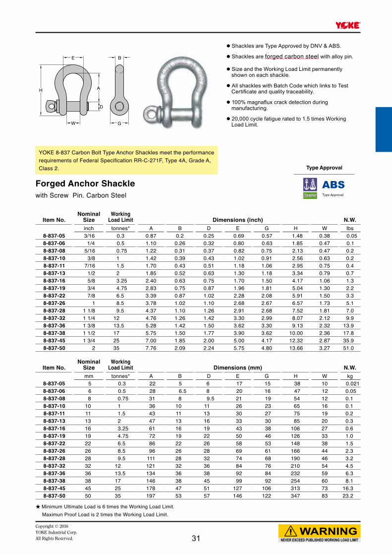
YOKE 8-837 Carbon Bolt Type Anchor Shackles meet the performance requirements of Federal Specification RR-C-271F, Type 4A, Grade A, Class 2.
Forged Anchor Shacklewith Screw Pin. Carbon Steel
★ Minimum Ultimate Load is 6 times the Working Load Limit. Maximun Proof Load is 2 times the Working Load Limit.
● Shackles are Type Approved by DNV & ABS.
● Shackles are forged carbon steel with alloy pin.
● Size and the Working Load Limit permanently shown on each shackle.
● All shackles with Batch Code which links to Test Certificate and quality traceability.
● 100% magnaflux crack detection during manufacturing.
● 20,000 cycle fatigue rated to 1.5 times Working Load Limit.
Type Approval
31
E
K
A
C C
H
D
W
B
G
R
E
K
A
C C
H
D
W
B
G
R
Item No.Nominal
SizeWorking
Load Limit Dimensions (inch) N.W.inch tonnes* A B C D E G H K R W lbs
8-809-19 3/4 7 3.58 1.61 0.70 0.87 1.26 1.81 5.90 4.09 1.26 1.30 3.78-809-26 1 12.5 4.64 2.12 0.91 1.14 1.61 2.40 7.64 5.51 1.38 1.73 8.48-809-32 1 1/4 18 5.83 2.52 1.18 1.42 2.00 2.68 9.37 6.77 1.50 2.13 14.78-809-38 1 1/2 30 6.93 3.15 1.38 1.77 2.50 3.50 11.38 8.50 1.77 2.36 27.5
Item No.Nominal
SizeWorking
Load Limit Dimensions (mm) N.W.mm tonnes* A B C D E G H K R W kg
8-809-19 19 7 91 41 18 22 32 46 150 104 32 33 1.78-809-26 26 12.5 118 54 23 29 41 61 194 140 35 44 3.88-809-32 32 18 148 64 30 36 51 68 238 172 38 54 6.78-809-38 38 30 176 80 35 45 64 89 289 216 45 60 12.5
Fig. 1
Fig. 2
NEVER EXCEED PUBLISHED WORKING LOAD LIMIT
WARNINGCopyright © 2016
YOKE Industrial Corp.All Rights Reserved.
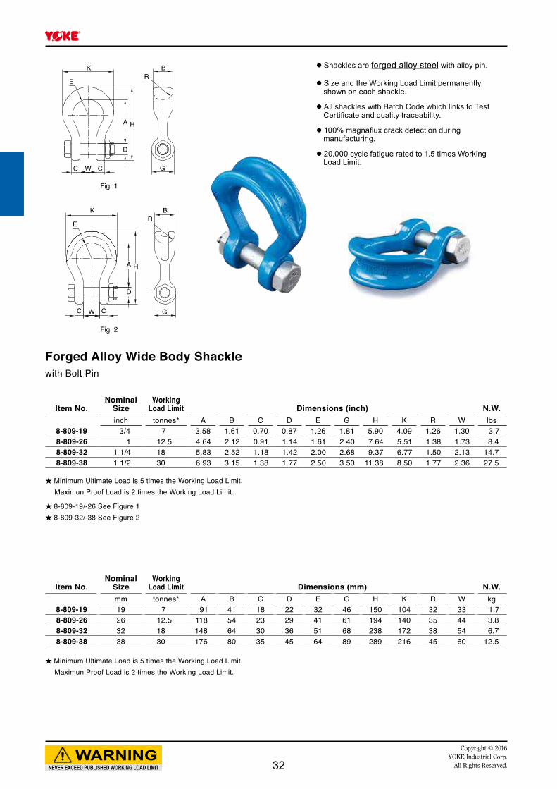
Forged Alloy Wide Body Shacklewith Bolt Pin
★ Minimum Ultimate Load is 5 times the Working Load Limit. Maximun Proof Load is 2 times the Working Load Limit.
★ Minimum Ultimate Load is 5 times the Working Load Limit. Maximun Proof Load is 2 times the Working Load Limit.
● Shackles are forged alloy steel with alloy pin.
● Size and the Working Load Limit permanently shown on each shackle.
● All shackles with Batch Code which links to Test Certificate and quality traceability.
● 100% magnaflux crack detection during manufacturing.
● 20,000 cycle fatigue rated to 1.5 times Working Load Limit.
★ 8-809-19/-26 See Figure 1★ 8-809-32/-38 See Figure 2
32

D
A
G
B
W
H
G
B
A
D
W
H
Type Approval
Type Approval
Item No.Nominal
SizeWorking
Load Limit Dimensions (mm) N.W.inch tonnes* A B D G H W kg
8-804-08 5/16 1.2 31 8 9.5 19 52 13 0.18-804-10 3/8 2 36 10 11 23 63 16 0.18-804-11 7/16 2.7 43 11 13 27 74 19 0.28-804-13 1/2 3.3 47 13 16 30 83 20 0.38-804-16 5/8 5 60 16 19 38 106 27 0.68-804-19 3/4 7 71 19 22 46 126 33 0.98-804-22 7/8 9.5 87 22 26 53 148 38 1.48-804-26 1 12.5 95 26 28 60 166 44 2.28-804-28 1 1/8 15 108 28 32 68 190 46 3.08-804-32 1 1/4 18 119 32 36 76 210 52 4.28-804-36 1 3/8 21 133 36 38 84 232 57 5.7
Item No.Nominal
SizeWorking
Load Limit Dimensions (mm) N.W.inch tonnes* A B D G H W kg
8-805-16 5/8 5 60 16 19 38 106 27 0.68-805-19 3/4 7 71 19 22 46 126 33 1.08-805-22 7/8 9.5 87 22 26 53 148 38 1.68-805-26 1 12.5 95 26 28 60 166 44 2.48-805-28 1 1/8 15 108 28 32 68 190 46 3.38-805-32 1 1/4 18 119 32 36 76 210 52 4.68-805-36 1 3/8 21 133 36 38 84 232 57 6.2
NEVER EXCEED PUBLISHED WORKING LOAD LIMIT
WARNINGCopyright © 2016 YOKE Industrial Corp.All Rights Reserved.
YOKE 8-805 Bolt Type Chain Shackles meet the performance requirements of Federal Specification RR-C-271F, Type 4B , Grade B, Class 3.
YOKE 8-804 Screw Type Chair Shackles meet the performance requirements of Federal Specification RR-C-271F, Type 4B , Grade B, Class 2.
Forged Alloy Chain Shacklewith Bolt Pin
Forged Alloy Chain Shacklewith Screw Pin
★ Minimum Ultimate Load is 5 times the Working Load Limit. Maximun Proof Load is 2 times the Working Load Limit.
★ Minimum Ultimate Load is 5 times the Working Load Limit. Maximun Proof Load is 2 times the Working Load Limit.
● Shackles are Type Approved by ABS.
● Shackles are forged alloy steel with alloy pin.
● Size and the Working Load Limit permanently shown on each shackle.
● All shackles with Batch Code which links to Test Certificate and quality traceability.
● 100% magnaflux crack detection during manufacturing.
● 20,000 cycle fatigue rated to 1.5 times Working Load Limit.
● Shackles are Type Approved by DNV & ABS.
● Shackles are forged alloy steel with alloy pin.
● Size and the Working Load Limit permanently shown on each shackle.
● All shackles with Batch Code which links to Test Certificate and quality traceability.
● 100% magnaflux crack detection during manufacturing.
● 20,000 cycle fatigue rated to 1.5 times Working Load Limit.
33

D
A
G
B
W
H
G
B
W
D
H
A
Item No.Nominal
SizeWorking
Load Limit Dimensions (mm) N.W.inch tonnes* A B D G H W kg
8-835-08 5/16 0.75 31 8 9.5 19 52 13 0.18-835-10 3/8 1 36 10 11 23 63 16 0.18-835-11 7/16 1.5 43 11 13 27 74 19 0.28-835-13 1/2 2 57 13 16 30 83 20 0.38-835-16 5/8 3.25 60 16 19 38 106 27 0.68-835-19 3/4 4.75 71 19 22 46 126 33 1.08-835-22 7/8 6.5 87 22 26 53 148 38 1.68-835-26 1 8.5 95 26 28 60 166 44 2.48-835-28 1 1/8 9.5 108 28 32 68 190 46 3.28-835-32 1 1/4 12 119 32 36 76 210 52 4.58-835-36 1 3/8 13.5 133 36 38 84 232 57 6.1
Item No.Nominal
SizeWorking
Load Limit Dimensions (mm) N.W.inch tonnes* A B D G H W kg
8-834-08 5/16 0.75 31 8 9.5 19 52 13 0.18-834-10 3/8 1 36 10 11 23 63 16 0.18-834-11 7/16 1.5 43 11 13 27 74 19 0.28-834-13 1/2 2 57 13 16 30 83 20 0.38-834-16 5/8 3.25 60 16 19 38 106 27 0.68-834-19 3/4 4.75 71 19 22 46 126 33 1.08-834-22 7/8 6.5 87 22 26 53 148 38 1.58-834-26 1 8.5 95 26 28 60 166 44 2.28-834-28 1 1/8 9.5 108 28 32 68 190 46 3.08-834-32 1 1/4 12 119 32 36 76 210 52 4.28-834-36 1 3/8 13.5 133 36 38 84 232 57 5.7
NEVER EXCEED PUBLISHED WORKING LOAD LIMIT
WARNINGCopyright © 2016
YOKE Industrial Corp.All Rights Reserved.
YOKE 8-835 Bolt Type Anchor Shackles meet the performance requirements of Federal Specification RR-C-271F, Type 4B , Grade A, Class 3.
YOKE 8-834 Screw Pin Chain Shackles meet the performance requirements of Federal Specification RR-C-271F, Type 4B , Grade A, Class 2.
Forged Chain Shacklewith Bolt Pin
Forged Chain Shacklewith Screw Pin
★ Minimum Ultimate Load is 6 times the Working Load Limit. Maximun Proof Load is 2 times the Working Load Limit.
★ Minimum Ultimate Load is 6 times the Working Load Limit. Maximun Proof Load is 2 times the Working Load Limit.
● Shackles are Type Approved by ABS.
● Shackles are forged carbon steel with alloy pin.
● Size and the Working Load Limit permanently shown on each shackle.
● All shackles with Batch Code which links to Test Certificate and quality traceability.
● 100% magnaflux crack detection during manufacturing.
● 20,000 cycle fatigue rated to 1.5 times Working Load Limit.
Type Approval
Type Approval
34
Copyright © 2016YOKE Industrial Corp.All Rights Reserved. 35

H
O
P W S
A
E
QT
Item No.Nominal
SizeWorking
Load Limit Dimensions (inch) N.W.inch mm tonnes* A E H O P Q S T W lbs
8-911-22 7/8 22 6.5 3.39 2.28 5.91 1.96 2.48 1.18 0.74 0.39 1.50 4.08-911-26 1 26 8.5 3.78 2.68 6.57 1.96 2.55 1.18 0.78 0.39 1.73 5.58-911-28 1 1/8 28 9.5 4.37 2.91 7.52 2.75 3.46 1.38 0.82 0.47 1.81 7.98-911-32 1 1/4 32 12.0 4.76 3.30 8.07 2.75 3.46 1.38 0.98 0.47 2.12 10.68-911-36 1 3/8 36 13.5 5.28 3.62 9.13 2.95 3.77 1.57 1.06 0.59 2.32 15.08-911-38 1 1/2 38 17.0 5.75 3.90 10.00 2.95 3.85 1.57 1.06 0.59 2.36 18.38-911-45 1 3/4 45 25.0 7.00 5.00 12.32 3.54 4.48 1.97 1.18 0.78 2.87 36.58-911-50 2 50 35.0 7.76 5.75 13.66 4.17 5.19 2.36 1.18 0.78 3.27 51.5
Item No.Nominal
SizeWorking
Load Limit Dimensions (mm) N.W.inch mm tonnes* A E H O P Q S T W kg
8-911-22 7/8 22 6.5 86 58 148 50 63 30 19 10 38 1.88-911-26 1 26 8.5 96 69 166 50 65 30 20 10 44 2.58-911-28 1 1/8 28 9.5 111 74 190 70 88 35 21 12 46 3.68-911-32 1 1/4 32 12.0 121 84 210 70 88 35 25 12 54 4.88-911-36 1 3/8 36 13.5 134 92 232 75 96 40 27 15 59 6.88-911-38 1 1/2 38 17.0 146 99 254 75 98 40 27 15 60 8.38-911-45 1 3/4 45 25.0 178 127 313 90 114 50 30 20 73 16.68-911-50 2 50 35.0 197 146 347 106 132 60 30 20 83 23.4
NEVER EXCEED PUBLISHED WORKING LOAD LIMIT
WARNINGCopyright © 2016
YOKE Industrial Corp.All Rights Reserved.
★ Minimum Ultimate Load is 5 times the Working Load Limit. Maximun Proof Load is 2 times the Working Load Limit.
★ Minimum Ultimate Load is 5 times the Working Load Limit. Maximun Proof Load is 2 times the Working Load Limit.
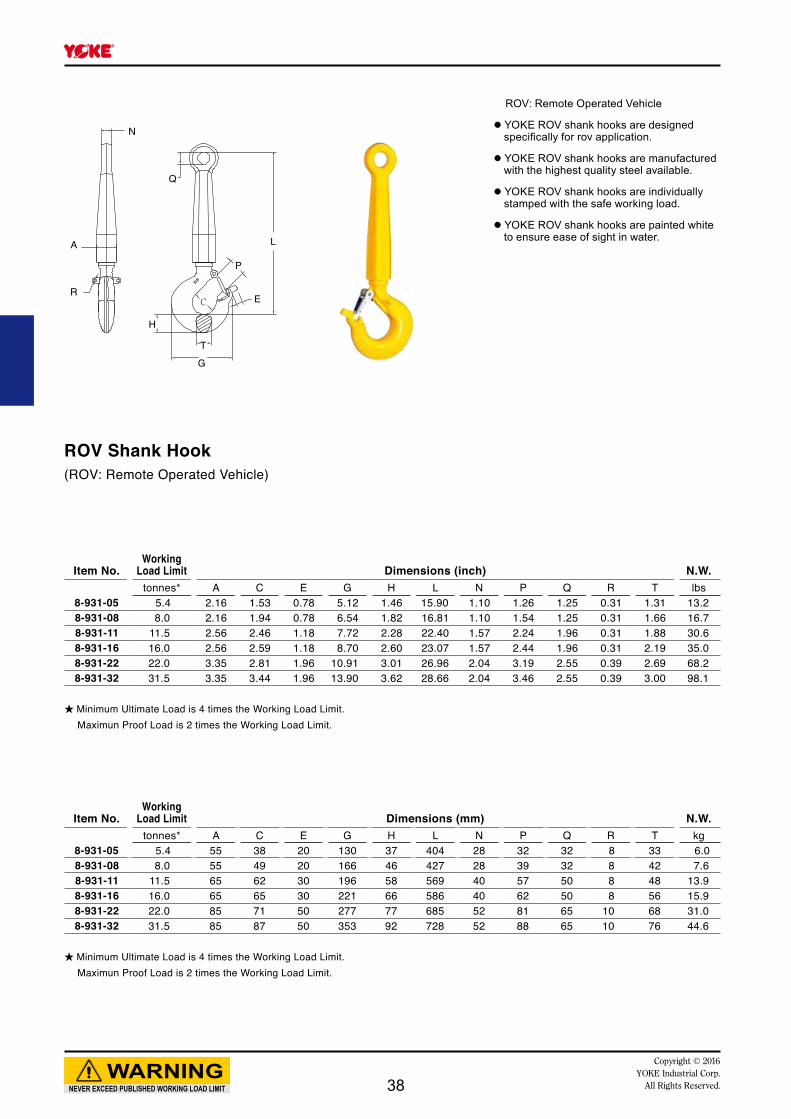
ROV: Remote Operated Vehicle
● YOKE ROV shackles are designed specifically for ROV application.
● YOKE ROV shackles are manufactured with the highest quality steel available.
● YOKE ROV shackles are individually stamped with the safe working load.
● YOKE ROV shackles are painted white to ensure ease of sight in water.
ROV Anchor Shackle with Safety Pin(ROV: Remote Operated Vehicle)
36

d
A
K R
H
T
D
E
P
Item No.Working
Load Limit Dimensions (inch) N.W.tonnes* A D d E H K P R T lbs
8-921-03 3.0 1.26 0.98 0.59 0.78 1.14 4.80 0.98 0.31 0.95 2.28-921-05 5.0 1.57 1.22 0.71 0.78 1.46 5.87 1.22 0.31 1.22 4.68-921-07 7.0 2.00 1.54 0.95 0.78 1.82 7.56 1.54 0.31 1.46 8.88-921-11 11.0 2.44 2.24 1.10 1.18 2.28 9.13 2.24 0.31 1.89 15.48-921-15 15.0 2.84 2.44 1.26 1.18 2.60 10.10 2.44 0.31 2.20 20.78-921-22 22.0 3.54 3.19 1.57 1.96 3.01 12.50 3.19 0.39 2.68 40.98-921-30 30.0 3.54 3.27 1.77 1.96 3.62 14.10 3.27 0.39 2.99 68.6
Item No.Working
Load Limit Dimensions (mm) N.W.tonnes A D d E H K P R T kg
8-921-03 3.0 32 25 15 20 29 122 25 8 24 1.08-921-05 5.0 40 31 18 20 37 149 31 8 31 2.18-921-07 7.0 51 39 24 20 46 192 39 8 37 4.08-921-11 11.0 62 57 28 30 58 232 57 8 48 7.08-921-15 15.0 72 62 32 30 66 256 62 8 56 9.48-921-22 22.0 90 81 40 50 77 318 81 10 68 18.68-921-30 30.0 90 83 45 50 92 357 83 10 76 31.2
NEVER EXCEED PUBLISHED WORKING LOAD LIMIT
WARNINGCopyright © 2016 YOKE Industrial Corp.All Rights Reserved.
★ Minimum Ultimate Load is 4 times the Working Load Limit. Maximun Proof Load is 2 times the Working Load Limit.
★ Minimum Ultimate Load is 4 times the Working Load Limit. Maximun Proof Load is 2 times the Working Load Limit.
ROV: Remote Operated Vehicle
● YOKE ROV hooks are designed specifically for ROV application.
● YOKE ROV hooks are manufactured with the highest quality steel available.
● YOKE ROV hooks are painted white to ensure ease of sight in water.
ROV Eye Sling Hook(ROV: Remote Operated Vehicle)
37
A
R
N
P
Q
L
E
T
G
H
Item No.Working
Load Limit Dimensions (inch) N.W.tonnes* A C E G H L N P Q R T lbs
8-931-05 5.4 2.16 1.53 0.78 5.12 1.46 15.90 1.10 1.26 1.25 0.31 1.31 13.28-931-08 8.0 2.16 1.94 0.78 6.54 1.82 16.81 1.10 1.54 1.25 0.31 1.66 16.78-931-11 11.5 2.56 2.46 1.18 7.72 2.28 22.40 1.57 2.24 1.96 0.31 1.88 30.68-931-16 16.0 2.56 2.59 1.18 8.70 2.60 23.07 1.57 2.44 1.96 0.31 2.19 35.08-931-22 22.0 3.35 2.81 1.96 10.91 3.01 26.96 2.04 3.19 2.55 0.39 2.69 68.28-931-32 31.5 3.35 3.44 1.96 13.90 3.62 28.66 2.04 3.46 2.55 0.39 3.00 98.1
Item No.Working
Load Limit Dimensions (mm) N.W.tonnes* A C E G H L N P Q R T kg
8-931-05 5.4 55 38 20 130 37 404 28 32 32 8 33 6.08-931-08 8.0 55 49 20 166 46 427 28 39 32 8 42 7.68-931-11 11.5 65 62 30 196 58 569 40 57 50 8 48 13.98-931-16 16.0 65 65 30 221 66 586 40 62 50 8 56 15.98-931-22 22.0 85 71 50 277 77 685 52 81 65 10 68 31.08-931-32 31.5 85 87 50 353 92 728 52 88 65 10 76 44.6
NEVER EXCEED PUBLISHED WORKING LOAD LIMIT
WARNINGCopyright © 2016
YOKE Industrial Corp.All Rights Reserved.
★ Minimum Ultimate Load is 4 times the Working Load Limit. Maximun Proof Load is 2 times the Working Load Limit.
★ Minimum Ultimate Load is 4 times the Working Load Limit. Maximun Proof Load is 2 times the Working Load Limit.
ROV: Remote Operated Vehicle
● YOKE ROV shank hooks are designed specifically for rov application.
● YOKE ROV shank hooks are manufactured with the highest quality steel available.
● YOKE ROV shank hooks are individually stamped with the safe working load.
● YOKE ROV shank hooks are painted white to ensure ease of sight in water.
ROV Shank Hook(ROV: Remote Operated Vehicle)
38

Copyright © 2016YOKE Industrial Corp.All Rights Reserved.
Bolt Lifting Points
39

8-271Swivel Point
8-231Anchor Point
8-203Hoist Ring
Num
ber o
f leg
s
Load
dire
ctio
n
Item
No.
Thre
ad S
ize
M 8
M 10
M 12
M 16
M 20
M 24
M 30
M 36
M 42
M 48
M 52
M 56
M 64
M 72
M 80
M 90
M 8
M 10
M 12
M 14
M 16
M 18
M 20
M 24
M 27
M 30
M 36
M 42
M 48
M 56
M 64
M 8
M 10
M 12
M 16
M 20
M 20
M 24
M 30
M 36
M 42
M48
1 0° 0.6 0.9 1.2 2.6 4 7 10 15 17 18 25 28 28 50 50 50 0.5 0.7 1 1.5 2 2.5 3 5 5.6 7.8 12.5 15.6 20 22 22.5 0.5 0.55 1.3 2.4 2.7 3.75 5.25 8.75 13.75 15.6 16.9
2 0° 1.2 1.8 2.4 5.2 8 14 20 30 34 36 50 56 56 100 100 100 1 1.4 2 3 4 5 6 10 11.2 15.6 25 31.2 40 44 45 1 1.1 2.6 4.8 5.4 7.5 10.5 17.5 27.5 31.2 33.8
1 90° 0.3 (0.4)
0.45 (0.6)
0.6 (0.7)
1.3 (1.5)
2 (2.5)
3.5 (4)
5 (6)
8 (10)
13 (13)
14 (16)
20 (20)
20 (22)
20 (22)
40(40)
40 (48)
40 (48) 0.5 0.7 1 1.5 2 2.5 3 5 5.6 7.8 12.5 15.6 20 22 22.5 0.5 0.55 1.3 2.4 2.7 3.75 5.25 8.75 13.75 15.6 16.9
2 90° 0.6 (0.8)
0.9 (1.2)
1.2 (1.5)
2.6 (3)
4 (5)
7 (8)
10 (12)
16 (20)
26 (26)
28 (32)
40 (40)
40 (44)
40 (44)
80 (80)
80 (96)
80 (96) 1 1.4 2 3 4 5 6 10 11.2 15.6 25 31.2 40 44 45 1 1.1 2.6 4.8 5.4 7.5 10.5 17.5 27.5 31.2 33.5
2 0-45° 0.4 0.6 0.8 1.8 2.8 4.9 7 11.2 (14)
18.2(18.2)
19.6(22.4)
28 (28)
28 (30.8)
28 (30.8)
56 (56)
56 (67.2)
56 (67.2) 0.7 1 1.4 2.1 2.8 3.5 4.2 7 7.8 10.9 17.5 21.8 28 30.8 31.5 0.7 0.77 1.82 3.36 3.78 5.25 7.35 12.25 19.25 21.84 23.66
2 45-60° 0.3 0.4 0.6 1.3 2 3.5 5 8 (10)
13(13)
14 (16)
20 (20)
20 (22)
20 (22)
40 (40)
40 (48)
40 (48) 0.5 0.7 1 1.5 2 2.5 3 5 5.6 7.8 12.5 15.6 20 22 22.5 0.5 0.55 1.3 2.4 2.7 3.75 5.25 8.75 13.75 15.6 16.9
2
unsy
mm.
0.3 0.4 0.6 1.3 2 3.5 5 8 (10)
13 (13)
14 (16)
20 (20)
20 (22)
20 (22)
40 (40)
40 (48)
40 (48) 0.5 0.7 1 1.5 2 2.5 3 5 5.6 7.8 12.5 15.6 20 22 22.5 0.5 0.55 1.3 2.4 2.7 3.75 5.25 8.75 13.75 15.6 16.9
3-4 0-45° 0.6 0.9 1.2 2.7 4.2 7.3 10.5 16.8 (21)
27.3 (27.3)
29.4 (33.6)
42 (42)
42 (46.2)
42 (46.2)
84 (84)
84 (100)
84 (100) 1.1 1.5 2.1 3.2 4.2 5.3 6.3 10.5 11.8 16.4 26.3 32.8 42 46.2 47.3 1.05 1.16 2.73 5.04 5.67 7.88 11.03 18.38 28.88 32.76 35.49
3-4 45-60° 0.4 0.6 0.9 1.9 3 5.2 7.5 12 (15)
19.5 (19.5)
21 (24)
30 (30)
30 (33)
30 (33)
60 (60)
60 (72)
60 (72) 0.8 1.1 1.5 2.3 3 3.8 4.5 7.5 8.4 11.7 18.8 23.4 30 33 33.8 0.75 0.83 1.95 3.6 4.05 5.63 7.88 13.13 20.63 23.4 25.35
3-4
unsy
mm.
0.3 0.4 0.6 1.3 2 3.5 5 8 (10)
13 (13)
14 (16)
20 (20)
20 (22)
20 (22)
40 (40)
40 (48)
40 (48) 0.5 0.7 1 1.5 2 2.5 3 5 5.6 7.8 12.5 15.6 20 22 22.5 0.5 0.55 1.3 2.4 2.7 3.75 5.25 8.75 13.75 15.6 16.9
Thread Size
M 8
M 10
M 12
M 16
M 20
M 24
M 30
M 36
M 42
M 48
M 52
M 56
M 64
M 72
M 80
M 90
M 8
M 10
M 12
M 14
M 16
M 18
M 20
M 24
M 27
M 30
M 36
M 42
M 48
M 56
M 64
M 8
M 10
M 12
M 16
M 20
M 20
M 24
M 30
M 36
M 42
M 48
8-27
1-00
3
8-27
1-00
4
8-27
1-00
6
8-27
1-01
3
8-27
1-02
0
8-27
1-03
5
8-27
1-06
0
8-27
1-08
0
8-27
1-12
0
8-27
1-13
0
8-27
1-14
0
8-27
1-16
0
8-27
1-16
1
8-27
1-31
0
8-27
1-35
0
8-27
1-40
0
8-23
1-00
5
8-23
1-00
7
8-23
1-01
0
8-23
1-01
5
8-23
1-02
0
8-23
1-02
5
8-23
1-03
0
8-23
1-05
0
8-23
1-05
6
8-23
1-07
8
8-23
1-12
5
8-23
1-15
6
8-23
1-20
0
8-23
1-22
0
8-23
1-22
5
8-20
3-00
4
8-20
3-00
5
8-20
3-01
0
8-20
3-01
9
8-20
3-02
1
8-20
3-03
0
8-20
3-04
2
8-20
3-07
0
8-20
3-11
0
8-20
3-12
5
8-20
3-13
5
NEVER EXCEED PUBLISHED WORKING LOAD LIMIT
WARNINGCopyright © 2016
YOKE Industrial Corp.All Rights Reserved.40

8-271Swivel Point
8-231Anchor Point
8-203Hoist Ring
Num
ber o
f leg
s
Load
dire
ctio
n
Item
No.
Thre
ad S
ize
M 8
M 10
M 12
M 16
M 20
M 24
M 30
M 36
M 42
M 48
M 52
M 56
M 64
M 72
M 80
M 90
M 8
M 10
M 12
M 14
M 16
M 18
M 20
M 24
M 27
M 30
M 36
M 42
M 48
M 56
M 64
M 8
M 10
M 12
M 16
M 20
M 20
M 24
M 30
M 36
M 42
M48
1 0° 0.6 0.9 1.2 2.6 4 7 10 15 17 18 25 28 28 50 50 50 0.5 0.7 1 1.5 2 2.5 3 5 5.6 7.8 12.5 15.6 20 22 22.5 0.5 0.55 1.3 2.4 2.7 3.75 5.25 8.75 13.75 15.6 16.9
2 0° 1.2 1.8 2.4 5.2 8 14 20 30 34 36 50 56 56 100 100 100 1 1.4 2 3 4 5 6 10 11.2 15.6 25 31.2 40 44 45 1 1.1 2.6 4.8 5.4 7.5 10.5 17.5 27.5 31.2 33.8
1 90° 0.3 (0.4)
0.45 (0.6)
0.6 (0.7)
1.3 (1.5)
2 (2.5)
3.5 (4)
5 (6)
8 (10)
13 (13)
14 (16)
20 (20)
20 (22)
20 (22)
40(40)
40 (48)
40 (48) 0.5 0.7 1 1.5 2 2.5 3 5 5.6 7.8 12.5 15.6 20 22 22.5 0.5 0.55 1.3 2.4 2.7 3.75 5.25 8.75 13.75 15.6 16.9
2 90° 0.6 (0.8)
0.9 (1.2)
1.2 (1.5)
2.6 (3)
4 (5)
7 (8)
10 (12)
16 (20)
26 (26)
28 (32)
40 (40)
40 (44)
40 (44)
80 (80)
80 (96)
80 (96) 1 1.4 2 3 4 5 6 10 11.2 15.6 25 31.2 40 44 45 1 1.1 2.6 4.8 5.4 7.5 10.5 17.5 27.5 31.2 33.5
2 0-45° 0.4 0.6 0.8 1.8 2.8 4.9 7 11.2 (14)
18.2(18.2)
19.6(22.4)
28 (28)
28 (30.8)
28 (30.8)
56 (56)
56 (67.2)
56 (67.2) 0.7 1 1.4 2.1 2.8 3.5 4.2 7 7.8 10.9 17.5 21.8 28 30.8 31.5 0.7 0.77 1.82 3.36 3.78 5.25 7.35 12.25 19.25 21.84 23.66
2 45-60° 0.3 0.4 0.6 1.3 2 3.5 5 8 (10)
13(13)
14 (16)
20 (20)
20 (22)
20 (22)
40 (40)
40 (48)
40 (48) 0.5 0.7 1 1.5 2 2.5 3 5 5.6 7.8 12.5 15.6 20 22 22.5 0.5 0.55 1.3 2.4 2.7 3.75 5.25 8.75 13.75 15.6 16.9
2
unsy
mm.
0.3 0.4 0.6 1.3 2 3.5 5 8 (10)
13 (13)
14 (16)
20 (20)
20 (22)
20 (22)
40 (40)
40 (48)
40 (48) 0.5 0.7 1 1.5 2 2.5 3 5 5.6 7.8 12.5 15.6 20 22 22.5 0.5 0.55 1.3 2.4 2.7 3.75 5.25 8.75 13.75 15.6 16.9
3-4 0-45° 0.6 0.9 1.2 2.7 4.2 7.3 10.5 16.8 (21)
27.3 (27.3)
29.4 (33.6)
42 (42)
42 (46.2)
42 (46.2)
84 (84)
84 (100)
84 (100) 1.1 1.5 2.1 3.2 4.2 5.3 6.3 10.5 11.8 16.4 26.3 32.8 42 46.2 47.3 1.05 1.16 2.73 5.04 5.67 7.88 11.03 18.38 28.88 32.76 35.49
3-4 45-60° 0.4 0.6 0.9 1.9 3 5.2 7.5 12 (15)
19.5 (19.5)
21 (24)
30 (30)
30 (33)
30 (33)
60 (60)
60 (72)
60 (72) 0.8 1.1 1.5 2.3 3 3.8 4.5 7.5 8.4 11.7 18.8 23.4 30 33 33.8 0.75 0.83 1.95 3.6 4.05 5.63 7.88 13.13 20.63 23.4 25.35
3-4
unsy
mm.
0.3 0.4 0.6 1.3 2 3.5 5 8 (10)
13 (13)
14 (16)
20 (20)
20 (22)
20 (22)
40 (40)
40 (48)
40 (48) 0.5 0.7 1 1.5 2 2.5 3 5 5.6 7.8 12.5 15.6 20 22 22.5 0.5 0.55 1.3 2.4 2.7 3.75 5.25 8.75 13.75 15.6 16.9
Thread Size
M 8
M 10
M 12
M 16
M 20
M 24
M 30
M 36
M 42
M 48
M 52
M 56
M 64
M 72
M 80
M 90
M 8
M 10
M 12
M 14
M 16
M 18
M 20
M 24
M 27
M 30
M 36
M 42
M 48
M 56
M 64
M 8
M 10
M 12
M 16
M 20
M 20
M 24
M 30
M 36
M 42
M 48
8-27
1-00
3
8-27
1-00
4
8-27
1-00
6
8-27
1-01
3
8-27
1-02
0
8-27
1-03
5
8-27
1-06
0
8-27
1-08
0
8-27
1-12
0
8-27
1-13
0
8-27
1-14
0
8-27
1-16
0
8-27
1-16
1
8-27
1-31
0
8-27
1-35
0
8-27
1-40
0
8-23
1-00
5
8-23
1-00
7
8-23
1-01
0
8-23
1-01
5
8-23
1-02
0
8-23
1-02
5
8-23
1-03
0
8-23
1-05
0
8-23
1-05
6
8-23
1-07
8
8-23
1-12
5
8-23
1-15
6
8-23
1-20
0
8-23
1-22
0
8-23
1-22
5
8-20
3-00
4
8-20
3-00
5
8-20
3-01
0
8-20
3-01
9
8-20
3-02
1
8-20
3-03
0
8-20
3-04
2
8-20
3-07
0
8-20
3-11
0
8-20
3-12
5
8-20
3-13
5
NEVER EXCEED PUBLISHED WORKING LOAD LIMIT
WARNINGCopyright © 2016 YOKE Industrial Corp.All Rights Reserved. 41

NEVER EXCEED PUBLISHED WORKING LOAD LIMIT
WARNINGCopyright © 2016
YOKE Industrial Corp.All Rights Reserved.42
8-211 Lifting Point
8-291K / 8-291Eye Point
Num
ber o
f leg
s
Load
dire
ctio
n
Item
No.
Thre
ad S
ize
M 8
M 10
M 12
M 14
M 16
M 18
M 20
M 24
M 27
M 30
M 36
M 36
M 42
M 42
M 48
M 8
M 10
M 12
M 16
M 20
M 24
M 30
M 36
M 42
M 48
M56
M64
1 0° 0.3 0.63 1 1.2 1.5 2 2.5 4 4 5 7 8 10 15 20 1 1 2 4 6 8 12 16 24 32 32 32
2 0° 0.6 1.26 2 2.4 3 4 5 8 8 10 14 16 20 30 40 2 2 4 8 12 16 24 32 48 64 64 64
1 90° 0.3 0.63 1 1.2 1.5 2 2.5 4 4 5 7 8 10 15 20 0.3 0.4 0.75 1.5 2.3 3.2 4.5 7 9 12 12 12
2 90° 0.6 1.26 2 2.4 3 4 5 8 8 10 14 16 20 30 40 0.6 0.8 1.5 3 4.6 6.4 9 14 18 24 24 24
2 0-45° 0.42 0.88 1.4 1.7 2.1 2.8 3.5 5.6 5.6 7 9.8 11.2 14 21 28 0.42 0.56 1 2.1 3.2 4.5 6.3 9.8 12.6 16.8 16.8 16.8
2 45-60° 0.3 0.63 1 1.2 1.5 2 2.5 4 4 5 7 8 10 15 20 0.3 0.4 0.75 1.5 2.3 3.2 4.5 7 9 12 12 12
2
unsy
mm.
0.3 0.63 1 1.2 1.5 2 2.5 4 4 5 7 8 10 15 20 0.3 0.4 0.75 1.5 2.3 3.2 4.5 7 9 12 12 12
3-4 0-45° 0.63 1.32 2.1 2.5 3.1 4.2 5.2 8.4 8.4 10.5 14.7 16.8 21 31.5 42 0.63 0.8 1.5 3.1 4.8 6.7 9.4 14.7 18.9 25 25 25
3-4 45-60° 0.45 0.95 1.5 1.8 2.2 3 3.7 6 6 7.5 10.5 12 15 22.5 30 0.45 0.6 1.1 2.2 3.4 4.8 6.7 10.5 13.5 18 18 18
3-4
unsy
mm.
0.3 0.63 1 1.2 1.5 2 2.5 4 4 5 7 8 10 15 20 0.3 0.4 0.75 1.5 2.3 3.2 4.5 7 9 12 12 12
Thread Size
M 8
M 10
M 12
M 14
M 16
M 18
M 20
M 24
M 27
M 30
M 36
M 36
M 42
M 42
M 48
M 8
M 10
M 12
M 16
M 20
M 24
M 30
M 36
M 42
M 48
M56
M64
8-21
1-00
3
8-21
1-00
6
8-21
1-01
0
8-21
1-01
2
8-21
1-01
5
8-21
1-02
0
8-21
1-02
5
8-21
1-04
0
8-21
1-04
2
8-21
1-05
0
8-21
1-07
0
8-21
1-08
0
8-21
1-10
0
8-21
1-15
0
8-21
1-20
0
8-29
1K-0
03
8-29
1K-0
04
8-29
1K-0
07
8-29
1K-0
15
8-29
1K-0
23
8-29
1K-0
32
8-29
1K-0
45
8-29
1K-0
70
8-29
1K-0
90
8-29
1K-1
20
8-29
1K-1
40
8-29
1K-1
50
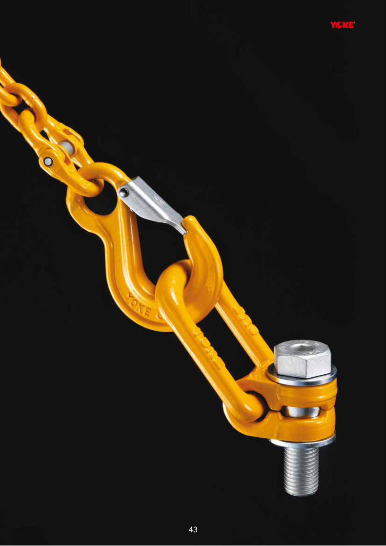
Copyright © 2016YOKE Industrial Corp.All Rights Reserved. 43
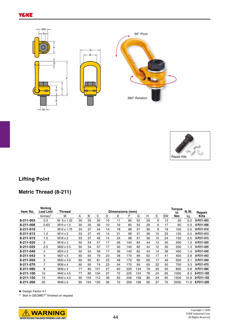
E
M
H C
F
A
D
G
B
SSW
360° Rotation
90° Pivot
Item No.Working
Load Limit Thread Dimensions (mm)Torque
inNm
N.W. Repair Kitstonnes* M A B C D E F G H S SW kg
8-211-003 0.3 M 8 x 1.25 30 35 35 10 11 85 55 29 6 13 30 0.2 8-P211-0038-211-006 0.63 M10 x 1.5 30 35 36 10 16 85 55 29 6 17 60 0.3 8-P211-0068-211-010 1 M12 x 1.75 33 37 44 14 18 98 57 36 8 19 100 0.5 8-P211-0108-211-012 1.2 M14 x 2 33 37 45 14 21 98 57 36 10 22 120 0.5 8-P211-0128-211-015 1.5 M16 x 2 33 37 46 14 24 98 57 36 10 24 150 0.5 8-P211-0158-211-020 2 M18 x 2 50 54 57 17 26 140 82 44 12 30 200 1.3 8-P211-0208-211-025 2.5 M20 x 2.5 50 54 57 17 30 140 82 44 12 30 250 1.3 8-P211-0258-211-040 4 M24 x 3 50 54 59 17 36 140 82 44 14 36 400 1.4 8-P211-0408-211-042 4 M27 x 3 60 65 79 23 38 170 99 62 17 41 400 2.8 8-P211-0428-211-050 5 M30 x 3.5 60 65 81 23 48 170 99 62 17 46 500 3.1 8-P211-0508-211-070 7 M36 x 4 60 65 74 23 54 170 99 65 22 55 700 3.3 8-P211-0708-211-080 8 M36 x 4 77 85 101 27 62 225 124 78 22 55 800 5.8 8-P211-0808-211-100 10 M42 x 4.5 77 85 104 27 72 225 124 78 24 65 1000 6.3 8-P211-1008-211-150 15 M42 x 4.5 95 104 112 36 63 256 158 86 24 65 1500 10.8 8-P211-1508-211-200 20 M48 x 5 95 104 120 36 72 259 158 90 27 75 2000 11.6 8-P211-200
★ Design Factor 4:1** Bolt in GEOMET® finished on request
NEVER EXCEED PUBLISHED WORKING LOAD LIMIT
WARNINGCopyright © 2016
YOKE Industrial Corp.All Rights Reserved.
Lifting Point
Metric Thread (8-211)
Repair Kits
44
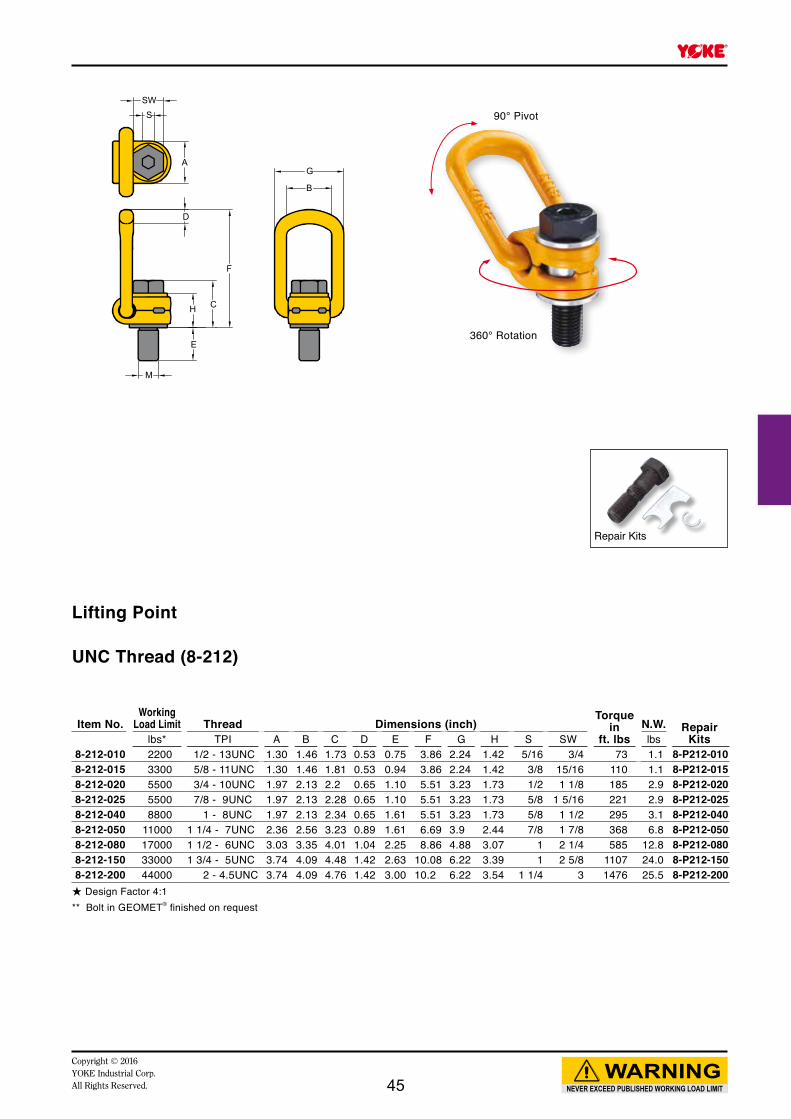
E
M
H C
F
A
D
G
B
SSW
360° Rotation
90° Pivot
Item No.Working
Load Limit Thread Dimensions (inch)Torque
inft. lbs
N.W. Repair Kitslbs* TPI A B C D E F G H S SW lbs
8-212-010 2200 1/2 - 13UNC 1.30 1.46 1.73 0.53 0.75 3.86 2.24 1.42 5/16 3/4 73 1.1 8-P212-0108-212-015 3300 5/8 - 11UNC 1.30 1.46 1.81 0.53 0.94 3.86 2.24 1.42 3/8 15/16 110 1.1 8-P212-0158-212-020 5500 3/4 - 10UNC 1.97 2.13 2.2 0.65 1.10 5.51 3.23 1.73 1/2 1 1/8 185 2.9 8-P212-0208-212-025 5500 7/8 - 9UNC 1.97 2.13 2.28 0.65 1.10 5.51 3.23 1.73 5/8 1 5/16 221 2.9 8-P212-0258-212-040 8800 1 - 8UNC 1.97 2.13 2.34 0.65 1.61 5.51 3.23 1.73 5/8 1 1/2 295 3.1 8-P212-0408-212-050 11000 1 1/4 - 7UNC 2.36 2.56 3.23 0.89 1.61 6.69 3.9 2.44 7/8 1 7/8 368 6.8 8-P212-0508-212-080 17000 1 1/2 - 6UNC 3.03 3.35 4.01 1.04 2.25 8.86 4.88 3.07 1 2 1/4 585 12.8 8-P212-0808-212-150 33000 1 3/4 - 5UNC 3.74 4.09 4.48 1.42 2.63 10.08 6.22 3.39 1 2 5/8 1107 24.0 8-P212-1508-212-200 44000 2 - 4.5UNC 3.74 4.09 4.76 1.42 3.00 10.2 6.22 3.54 1 1/4 3 1476 25.5 8-P212-200★ Design Factor 4:1** Bolt in GEOMET® finished on request
NEVER EXCEED PUBLISHED WORKING LOAD LIMIT
WARNINGCopyright © 2016 YOKE Industrial Corp.All Rights Reserved.
Repair Kits
Lifting Point
UNC Thread (8-212)
45
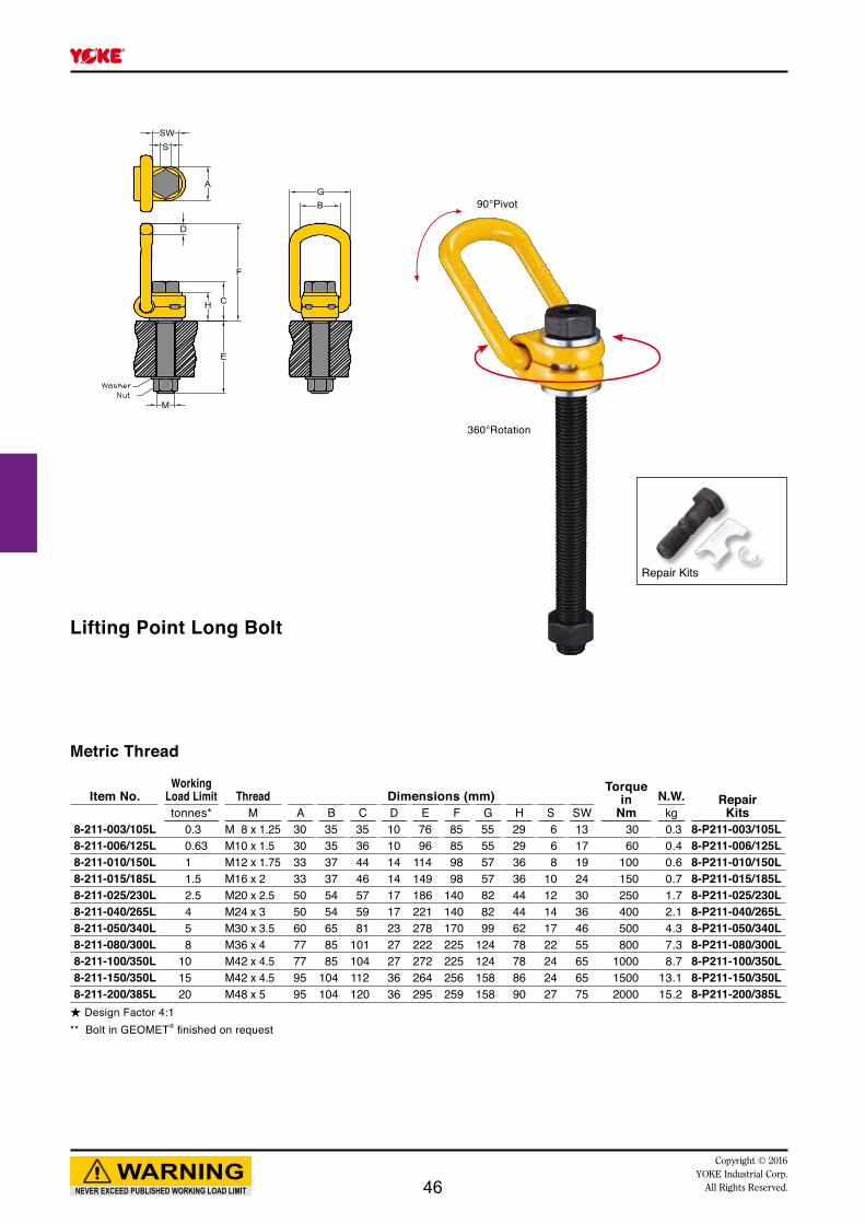
MM
EE
HH
DD
CC
FF
AA
SSSWSW
GGBB 90°Pivot
Repair Kits
360°Rotation
Lifting Point Long Bolt
Metric Thread
Item No.Working
Load Limit Thread Dimensions (mm)Torque
inNm
N.W. RepairKitstonnes* M A B C D E F G H S SW kg
8-211-003/105L 0.3 M 8 x 1.25 30 35 35 10 76 85 55 29 6 13 30 0.3 8-P211-003/105L8-211-006/125L 0.63 M10 x 1.5 30 35 36 10 96 85 55 29 6 17 60 0.4 8-P211-006/125L8-211-010/150L 1 M12 x 1.75 33 37 44 14 114 98 57 36 8 19 100 0.6 8-P211-010/150L8-211-015/185L 1.5 M16 x 2 33 37 46 14 149 98 57 36 10 24 150 0.7 8-P211-015/185L8-211-025/230L 2.5 M20 x 2.5 50 54 57 17 186 140 82 44 12 30 250 1.7 8-P211-025/230L8-211-040/265L 4 M24 x 3 50 54 59 17 221 140 82 44 14 36 400 2.1 8-P211-040/265L8-211-050/340L 5 M30 x 3.5 60 65 81 23 278 170 99 62 17 46 500 4.3 8-P211-050/340L8-211-080/300L 8 M36 x 4 77 85 101 27 222 225 124 78 22 55 800 7.3 8-P211-080/300L8-211-100/350L 10 M42 x 4.5 77 85 104 27 272 225 124 78 24 65 1000 8.7 8-P211-100/350L8-211-150/350L 15 M42 x 4.5 95 104 112 36 264 256 158 86 24 65 1500 13.1 8-P211-150/350L8-211-200/385L 20 M48 x 5 95 104 120 36 295 259 158 90 27 75 2000 15.2 8-P211-200/385L
★ Design Factor 4:1** Bolt in GEOMET® finished on request
NEVER EXCEED PUBLISHED WORKING LOAD LIMIT
WARNINGCopyright © 2016
YOKE Industrial Corp.All Rights Reserved.46

Copyright © 2016YOKE Industrial Corp.All Rights Reserved. 4747

Key
360° Rotation
Key Eye Point
CC
DD
AA
FF
EE
MM
BB
WW
SS
PatentX
X
X
X
X
X
Load direction
-Nominal WLL- Vertical load-straight pull-
()-Values
z
Metric Thread (8-291K)
Item No.Working
Load Limit Thread Dimensions (mm)Torque
in Nm
N.W.tonnes* M A B C D E F S W kg Key
x ( z )8-291K-003 0.3 ( 1) M 8 x 1.25 36 25 8 9 12 25 6 44 10 0.1 8-P291K-0048-291K-004 0.4 ( 1) M10 x 1.5 36 25 8 9 15 25 6 44 10 0.1 8-P291K-0048-291K-007 0.75 ( 2) M12 x 1.75 45 30 10 11 18 33 8 52 10 0.2 8-P291K-0078-291K-015 1.5 ( 4) M16 x 2 52 35 14 13 24 35 10 61 30 0.3 8-P291K-0158-291K-023 2.3 ( 6) M20 x 2.5 60 40 16 15 30 44 12 70 70 0.6 8-P291K-0238-291K-032 3.2 ( 8) M24 x 3 72 48 19 18 36 52 14 84 150 1.0 8-P291K-0328-291K-045 4.5 (12) M30 x 3.5 90 60 24 22 45 60 17 105 350 1.8 8-P291K-0458-291K-070 7.0 (16) M36 x 4 109 72 29 27 54 76 22 126 410 3.2 8-P291K-0708-291K-090 9.0 (24) M42 x 4.5 123 82 34 32 63 88 24 147 550 5.0 8-P291K-0908-291K-120 12.0 (32) M48 x 5 144 94 38 37 72 104 27 168 550 7.6 8-P291K-1208-291K-140 12.0 (32) M56 x 5.5 147 102 40 43 84 124 27 178 800 9.2 8-P291K-1508-291K-150 12.0 (32) M64 x 6 147 102 40 43 95 124 27 178 800 10.0 8-P291K-150
★ Design Factor 4:1** Bolt in GEOMET® finished on request
UNC Thread (8-292K)
Item No.Working
Load Limit Thread Dimensions (inch)Torque
inft. lbs
N.W.Keylbs* TPI A B C D E F S W lbs
x ( z )8-292K-003 660 ( 2200) 5/16 - 18UNC 1.42 0.98 0.31 0.35 0.47 0.98 0.25 1.73 7 0.2 8-P292K-0048-292K-004 880 ( 2200) 3/8 - 16UNC 1.42 0.98 0.31 0.35 0.57 0.98 0.25 1.73 7 0.2 8-P292K-0048-292K-007 1650 ( 4400) 1/2 - 13UNC 1.77 1.18 0.39 0.43 0.75 1.30 0.31 2.05 7 0.4 8-P292K-0078-292K-015 3300 ( 8800) 5/8 - 11UNC 2.05 1.38 0.55 0.51 0.94 1.38 0.37 2.40 20 0.7 8-P292K-0158-292K-023 5060 (13200) 3/4 - 10UNC 2.36 1.57 0.63 0.59 1.13 1.73 0.50 2.76 50 1.3 8-P292K-0238-292K-025 5060 (13200) 7/ 8 - 9UNC 2.36 1.57 0.63 0.59 1.31 1.73 0.50 2.76 50 1.3 8-P292K-0258-292K-032 7040 (17600) 1 - 8UNC 2.83 1.89 0.75 0.71 1.50 2.05 0.56 3.31 110 2.2 8-P292K-0328-292K-045 9900 (26400) 1 1/4 - 7UNC 3.54 2.36 0.94 0.87 1.88 2.36 0.63 4.13 250 4.0 8-P292K-0458-292K-070 15400 (35200) 1 1/2 - 6UNC 4.29 2.83 1.14 1.06 2.25 2.99 0.87 4.96 300 7.0 8-P292K-0708-292K-090 19800 (52800) 1 3/4 - 5UNC 4.84 3.23 1.34 1.26 2.63 3.46 1.00 5.79 400 11.0 8-P292K-0908-292K-120 26400 (70400) 2 - 4.5UNC 5.67 3.70 1.50 1.46 3.00 4.09 1.00 6.61 400 16.7 8-P292K-120
★ Design Factor 4:1** Bolt in GEOMET® finished on request
NEVER EXCEED PUBLISHED WORKING LOAD LIMIT
WARNINGCopyright © 2016
YOKE Industrial Corp.All Rights Reserved.48

360° Rotation
Patent
Eye Point
CC
DD
AA
FF
EE
MM
BB
WW
SS
Repair Kits
Load direction
-Nominal WLL- Vertical load-straight pull-
()-Values
z
Metric Thread (8-291)
Item No.Working
Load Limit Thread Dimensions (mm)Torque
in Nm
N.W. RepairKitstonnes* M A B C D E F S W kg
x ( z )8-291-003 0.3 ( 1) M 8 x 1.25 36 25 8 9 12 25 6 44 10 0.1 8-P291-0038-291-004 0.4 ( 1) M10 x 1.5 37 25 8 9 15 25 6 44 10 0.1 8-P291-0048-291-007 0.75 ( 2) M12 x 1.75 45 30 10 11 18 33 8 52 10 0.2 8-P291-0078-291-015 1.5 ( 4) M16 x 2 52 35 14 13 24 35 10 61 30 0.3 8-P291-0158-291-023 2.3 ( 6) M20 x 2.5 60 40 16 15 30 44 12 70 70 0.6 8-P291-0238-291-032 3.2 ( 8) M24 x 3 72 48 19 18 36 52 14 84 150 1.0 8-P291-0328-291-045 4.5 (12) M30 x 3.5 90 60 24 22 45 60 17 105 350 1.8 8-P291-0458-291-070 7.0 (16) M36 x 4 109 72 29 27 54 76 22 126 410 3.2 8-P291-0708-291-090 9.0 (24) M42 x 4.5 123 82 34 32 63 88 24 147 550 5.0 8-P291-0908-291-120 12.0 (32) M48 x 5 144 94 38 37 72 104 27 168 550 7.6 8-P291-1208-291-140 12.0 (32) M56 x 5.5 147 102 40 43 84 124 27 178 800 9.2 8-P291-1408-291-150 12.0 (32) M64 x 6 147 102 40 43 95 124 27 178 800 10.0 8-P291-150
★ Design Factor 4:1** Bolt in GEOMET® finished on request
UNC Thread (8-292)
Item No.Working
Load Limit Thread Dimensions (inch)Torque
inft. lbs
N.W. RepairKitslbs* TPI A B C D E F S W lbs
x ( z )8-292-003 660 ( 2200) 5/16 - 18UNC 1.42 0.98 0.31 0.35 0.47 0.98 0.25 1.73 7 0.2 8-P292-0038-292-004 880 ( 2200) 3/8 - 16UNC 1.46 0.98 0.31 0.35 0.57 0.98 0.25 1.73 7 0.2 8-P292-0048-292-007 1650 ( 4400) 1/2 - 13UNC 1.77 1.18 0.39 0.43 0.75 1.30 0.31 2.05 7 0.4 8-P292-0078-292-015 3300 ( 8800) 5/8 - 11UNC 2.05 1.38 0.55 0.51 0.94 1.38 0.37 2.40 20 0.7 8-P292-0158-292-023 5060 (13200) 3/4 - 10UNC 2.36 1.57 0.63 0.59 1.13 1.73 0.50 2.76 50 1.3 8-P292-0238-292-025 5060 (13200) 7/ 8 - 9UNC 2.36 1.57 0.63 0.59 1.31 1.73 0.50 2.76 50 1.3 8-P292-0258-292-032 7040 (17600) 1 - 8UNC 2.83 1.89 0.75 0.71 1.50 2.05 0.56 3.31 110 2.2 8-P292-0328-292-045 9900 (26400) 1 1/4 - 7UNC 3.54 2.36 0.94 0.87 1.88 2.36 0.63 4.13 250 4.0 8-P292-0458-292-070 15400 (35200) 1 1/2 - 6UNC 4.29 2.83 1.14 1.06 2.25 2.99 0.87 4.96 300 7.0 8-P292-0708-292-090 19800 (52800) 1 3/4 - 5UNC 4.84 3.23 1.34 1.26 2.63 3.46 1.00 5.79 400 11.0 8-P292-0908-292-120 26400 (70400) 2 - 4.5UNC 5.67 3.70 1.50 1.46 3.00 4.09 1.00 6.61 400 16.7 8-P292-120
★ Design Factor 4:1** Bolt in GEOMET® finished on request
NEVER EXCEED PUBLISHED WORKING LOAD LIMIT
WARNINGCopyright © 2016 YOKE Industrial Corp.All Rights Reserved. 49

E
M K
CC
BB
AADD
FF
G
Metric Thread (8-271)
Item No.Working
Load Limit Thread Dimensions (mm)Torque
in Nm
N.W.tonnes* M A B C D E F G K kg
x ( y ) [ z ]
8-271-003 0.3 (0.4) [0.6] M 8 x 1.25 29 32 40 8 12 72 35 30 10 0.28-271-004 0.45 (0.6) [0.9] M10 x 1.5 29 32 40 8 15 72 35 30 10 0.28-271-006 0.6 (0.7) [1.2] M12 x 1.75 35 50 45 10 18 95 40 36 10 0.38-271-013 1.3 (1.5) [2.6] M16 x 2 38 50 54 13 24 104 46 41 30 0.58-271-020 2 (2.5) [ 4] M20 x 2.5 38 54 68 13 30 122 62 55 70 1.08-271-035 3.5 ( 4) [ 7] M24 x 3 40 66 88 19 36 154 78 70 150 2.28-271-060 5 ( 6) [ 10] M30 x 3.5 50 86 120 22 46 206 90 80 350 4.58-271-080 8 ( 10) [ 15] M36 x 4 50 86 120 22 55 206 90 80 410 4.68-271-120 13 ( 13) [ 17] M42 x 4.5 65 110 122 25 64 235 98 84 550 5.58-271-130 14 ( 16) [ 18] M48 x 5 65 110 122 25 73 235 98 84 550 6.18-271-140 20 ( 20) [ 25] M52 x 5 70 120 150 32 79 270 120 94 750 10.58-271-160 20 ( 22) [ 28] M56 x 5.5 70 120 150 32 85 270 120 94 800 10.78-271-161 20 ( 22) [ 28] M64 x 6 70 120 150 32 95 270 120 94 800 11.68-271-310 40 ( 40) [ 50] M72 x 6 90 130 210 45 108 340 170 145 1200 30.68-271-350 40 ( 48) [ 50] M80 x 6 90 130 210 45 120 340 170 145 1500 31.98-271-400 40 ( 48) [ 50] M90 x 6 90 130 210 45 135 340 170 145 2000 33.9
★ Design Factor 4:1※ Thread M33, M39, M45, up to M150 are available upon request
Swivel Point
x y
zLoad direction
Worst case -Nominal WLL-Ring not adjusted to pull direction
Manually adjusted-increased WLL-( )-Values
Vertical load-straight pull-[ ]-Values
180° Pivot
360° Rotation
Ball Bearing Inside
NEVER EXCEED PUBLISHED WORKING LOAD LIMIT
WARNINGCopyright © 2016
YOKE Industrial Corp.All Rights Reserved.50

E
M K
CC
BB
AADD
FF
G
UNC Thread (8-272)
Item No.Working
Load Limit Thread Dimensions (inch)Torque
inft. lbs
N.W.lbs* TPI A B C D E F G K lbs
x ( y ) [ z ]
8-272-006 1320 ( 1550) [ 2650] 1/2 - 13UNC 1.38 1.97 1.77 0.39 0.75 3.74 1.57 1.42 7 0.78-272-013 2860 ( 3300) [ 5720] 5/8 - 11UNC 1.50 1.97 2.13 0.51 0.94 4.09 1.81 1.61 20 1.28-272-018 3960 ( 4400) [ 7900] 3/4 - 10UNC 1.50 1.97 2.68 0.51 1.13 4.09 1.81 1.61 20 1.28-272-020 4400 ( 5500) [ 8800] 7/8 - 9UNC 1.50 2.13 2.68 0.51 1.31 4.80 2.44 2.17 50 2.28-272-035 7700 ( 8800) [ 15400] 1 - 8UNC 1.57 2.60 3.46 0.75 1.50 6.06 3.07 2.76 110 4.88-272-060 11000 ( 13200) [ 22000] 1 1/4 - 7UNC 1.97 3.39 4.72 0.87 1.88 8.11 3.54 3.15 250 9.98-272-080 17600 ( 22000) [ 33000] 1 1/2 - 6UNC 1.97 3.39 4.72 0.87 2.25 8.11 3.54 3.15 300 10.08-272-120 28600 ( 28600) [ 37400] 1 3/4 - 5UNC 2.56 4.33 4.80 0.98 2.63 9.25 3.86 3.31 400 12.18-272-130 30800 ( 35200) [ 39600] 2 - 4.5UNC 2.56 4.33 4.80 0.98 3.00 9.25 3.86 3.31 400 13.58-272-140 44000 ( 44000) [ 55000] 2 1/4 - 4.5UNC 2.76 4.72 5.91 1.26 3.38 10.63 4.72 3.70 550 23.18-272-160 44000 ( 48400) [ 61600] 2 1/2 - 4UNC 2.76 4.72 5.91 1.26 3.75 10.63 4.72 3.70 590 23.58-272-310 88000 ( 88000) [110000] 3 - 4UNC 3.54 5.12 8.27 1.77 4.50 13.39 6.69 5.71 880 67.38-272-350 92400 (105600) [110000] 3 1/2 - 4UNC 3.54 5.12 8.27 1.77 5.25 13.39 6.69 5.71 1100 70.28-272-400 92400 (105600) [110000] 4 - 4UNC 3.54 5.12 8.27 1.77 6.00 13.39 6.69 5.71 1470 74.6
★ Design Factor 4:1※ Thread up to 6" are available upon request
Swivel Point
180° Pivot
360° Rotation
Ball Bearing Inside
x y
zLoad direction
Worst case -Nominal WLL-Ring not adjusted to pull direction
Manually adjusted-increased WLL-( )-Values
Vertical load-straight pull-[ ]-Values
NEVER EXCEED PUBLISHED WORKING LOAD LIMIT
WARNINGCopyright © 2016 YOKE Industrial Corp.All Rights Reserved. 51

Patent PendingAnchor Point
UNC Thread (8-232)
Item No.
Working Load Limit Thread Dimensions (inch)
Torquein
ft. lbsRepair
Kitslbs* TPI A B C D E F G H R S SW lbs8-232-010 1700 1/2 - 13 UNC 1.3 1.57 1.2 0.41 0.81 3.17 2.28 0.9 0.67 5/16 3/4 73 1.8 8-P232-0108-232-020 3500 5/8 - 11 UNC 1.97 2.13 1.81 0.65 1.13 4.61 3.54 1.42 1.06 3/8 15/16 110 2.0 8-P232-0208-232-030 5300 3/4 - 10 UNC 1.97 2.07 1.89 0.65 1.54 4.61 3.54 1.42 1.06 1/2 1 1/8 185 2.2 8-P232-0308-232-038 6700 7/8 - 9 UNC 2.56 2.99 2.28 0.79 1.42 6.02 4.25 1.73 1.34 5/8 1 5/16 221 4.3 8-P232-0388-232-050 8800 1 - 8 UNC 2.81 3.17 2.34 0.98 1.61 6.38 4.92 1.73 1.46 5/8 1 1/2 295 5.7 8-P232-0508-232-078 13700 1 1/4 - 7 UNC 3.43 3.66 3.23 1.18 2.09 8.07 5.83 2.44 1.79 7/8 1 7/8 368 11.0 8-P232-0788-232-125 22000 1 1/2 - 6 UNC 4.29 4.38 3.87 1.42 2.4 9.92 7.40 3.07 2.22 1 2 1/4 585 21.2 8-P232-1258-232-200 35200 2 - 4.5 UNC 4.61 3.80 4.46 1.42 3.00 9.93 7.71 3.35 2.38 1 1/4 3 1476 25.6 8-P232-200★ Design Factor 5:1** Bolt in GEOMET® finished on request
Metric Thread (8-231)
Item No.
Working LoadLimit Thread Dimensions (mm)
Torquein
NmN.W. Repair
Kitstonnes* M A B C D E F G H R S SW kg5:1 4:1
8-231-005 0.4 0.5 M 8 x 1.25 33 42 28 11 12 80 58 23 17 6 13 30 0.3 8-P231-0058-231-007 0.56 0.7 M10 x 1.5 33 41 29 11 15 80 58 23 17 6 17 60 0.3 8-P231-0078-231-010 0.8 1.0 M12 x 1.75 33 40 31 11 20 80 58 23 17 8 19 100 0.3 8-P231-0108-231-015 1.2 1.5 M14 x 2 50 56 45 17 21 117 90 36 27 10 22 120 0.9 8-P231-0158-231-020 1.6 2.0 M16 x 2 50 54 46 17 24 117 90 36 27 10 24 150 0.9 8-P231-0208-231-025 2.0 2.5 M18 x 2.5 65 78 57 20 26 153 108 44 34 12 30 200 1.9 8-P231-0258-231-030 2.4 3.0 M20 x 2.5 50 52 49 17 30 117 90 36 27 12 30 250 1.0 8-P231-0308-231-050 4.0 5.0 M24 x 3 72 81 59 25 36 163 125 44 37 14 36 400 2.6 8-P231-0508-231-056 4.5 5.6 M27 x 3 87 96 79 30 38 204 148 62 46 17 41 400 4.9 8-P231-0568-231-078 6.25 7.8 M30 x 3.5 87 94 81 30 48 204 148 62 46 17 46 500 5.0 8-P231-0788-231-125 10.0 12.5 M36 x 4 110 112 98 36 54 247 188 75 57 22 55 1000 9.6 8-P231-1258-231-156 12.5 15.6 M42 x 4.5 110 101 108 36 63 247 188 83 57 24 65 1500 10.9 8-P231-1568-231-200 16.0 20.0 M48 x 5 110 97 113 36 72 248 188 83 57 27 75 2000 11.6 8-P231-2008-231-220 17.6 22.0 M56 x 5.5 123 116 121 36 84 274 202 91 64 27 85 2100 15.0 8-P231-2208-231-225 18.0 22.5 M64 x 6 123 111 126 36 100 274 202 91 64 32 95 2200 16.3 8-P231-225
* Proof Load is 2.5 times the Working Load Limit on the 4:1 design factor.** Bolt in GEOMET® finished on request
RD
SSW
BF
C
E
H
MAG
180° Pivot
360°Rotation
Repair Kits
NEVER EXCEED PUBLISHED WORKING LOAD LIMIT
WARNINGCopyright © 2016
YOKE Industrial Corp.All Rights Reserved.52

Patent Pending
E
C
FB
RD
SSW
H
MAG
Repair Kits
180° Pivot
360°Rotation
Anchor Point Long Bolt
Metric Thread
Item No.
Working LoadLimit Thread Dimensions (mm)
Torquein
NmN.W. Repair
Kitstonnes* M A B C D E F G H R S SW kg5:1 4:1
8-231-005/105L 0.4 0.5 M 8 x 1.25 33 42 28 11 83 80 58 23 17 6 13 30 0.3 8-P231-005/105L8-231-007/125L 0.56 0.7 M10 x 1.5 33 41 29 11 103 80 58 23 17 6 17 60 0.4 8-P231-007/125L8-231-010/150L 0.80 1 M12 x 1.75 33 40 31 11 128 80 58 23 17 8 19 100 0.4 8-P231-010/150L8-231-020/185L 1.6 2 M16 x 2 50 54 46 17 149 117 90 36 27 10 24 150 1.1 8-P231-020/185L8-231-030/230L 2.4 3 M20 x 2.5 50 52 49 17 194 117 90 36 27 12 30 250 1.4 8-P231-030/230L8-231-050/265L 4 5 M24 x 3 72 81 59 25 221 163 125 44 37 14 36 400 3.2 8-P231-050/265L8-231-078/340L 6.25 7.8 M30 x 3.5 87 94 81 30 278 204 148 62 46 17 46 500 6.3 8-P231-078/340L8-231-125/300L 10 12.5 M36 x 4 110 112 98 36 225 247 188 75 57 22 55 1000 10.9 8-P231-125/300L8-231-156/350L 12.5 15.6 M42 x 4.5 110 101 108 36 268 247 188 83 57 24 65 1500 13.9 8-P231-156/350L8-231-200/385L 16 20 M48 x 5 110 97 113 36 303 248 188 83 57 27 75 2000 14.7 8-P231-200/385L* Proof Load is 2.5 times the Working Load Limit on the 4:1 design factor.** Bolt in GEOMET® finished on request
NEVER EXCEED PUBLISHED WORKING LOAD LIMIT
WARNINGCopyright © 2016 YOKE Industrial Corp.All Rights Reserved. 53

NEVER EXCEED PUBLISHED WORKING LOAD LIMIT
WARNINGCopyright © 2016
YOKE Industrial Corp.All Rights Reserved.
YOKE HOIST RINGS
Introduction: ● Designed for lifting heavy loads, YOKE Hoist Ring is innovative and meets all requirements of occupational health and safety.
● Modern design and construction provide the most dependable lifting and lashing mean with the easiest fitting for heavy loads of different material and shape.
● Due to its ball bearing construction, YOKE Hoist Ring rotates freely through 360º. This free movement makes it easy to handle and turns it automatically in direction of load.
Main Features: ● Easy to install – needs only one tap hole. ● Supplying both Bushing type and Ball bearing inside.
● Rotates thru 360º Pivots thru 180º ● Designed safety factor 5:1. ● 100% rated at 90º angle. ● 100% magnaflux crack detection. ● Proof load tested to 2.5 times W.L.L. and certified. ● 20,000 cycle fatigue rated to 1.5 times W.L.L. ● Each product has a batch code for material traceability and links to Test Certificate.
● Drop forged Suspension Ring. ● The Bolt has a result of Charpy-V-test according to
EN 10045, part 1 of at least 27 Joules at -20º C. ● Bolt are both UNC grade 8 per ASTM A 574 and
Metric Grade 12.9 per DIN EN ISO 4762. ● Multi directional loading. ● Self aligns in direction of load. ● Avoids torsion forces to the suspension ring
- more safety. ● No friction transferred to the bolt as it turns
- longer lifetime. ● The Bolt with galvanized alternative Phosphate
treatment for increased corrosion protection.
54
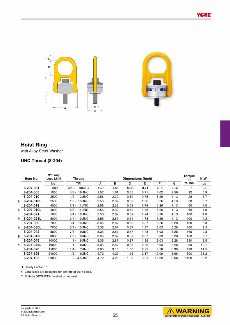
F
E
G
D
B
AM
Item No.Working
Load Limit Thread Dimensions (inch)Torque
inft. lbs
N.W.lbs* TPI A B D E F G lbs
8-204-004 800 5/16 - 18UNC 1.57 1.61 0.35 0.71 4.02 2.56 7 0.98-204-005 1000 3/8 - 16UNC 1.57 1.61 0.35 0.71 4.02 2.56 12 0.98-204-010 2500 1/2 - 13UNC 2.56 2.32 0.59 0.75 6.26 4.13 28 3.78-204-010L 2500 1/2 - 13UNC 2.56 2.32 0.59 1.26 6.26 4.13 28 3.78-204-019 4000 5/8 - 11UNC 2.56 2.32 0.59 0.74 6.26 4.13 60 4.08-204-019L 4000 5/8 - 11UNC 2.56 2.32 0.59 1.75 6.26 4.13 60 4.08-204-021 5000 3/4 - 10UNC 2.56 2.87 0.59 1.24 6.26 4.13 100 4.08-204-021L 5000 3/4 - 10UNC 2.56 2.87 0.59 1.73 6.26 4.13 100 4.28-204-030 7000 3/4 - 10UNC 3.35 2.87 0.59 0.87 6.26 5.28 100 8.88-204-030L 7000 3/4 - 10UNC 3.35 2.87 0.87 1.87 8.03 5.28 100 9.58-204-042 8000 7/8 - 9UNC 3.35 2.87 0.87 1.43 8.03 5.28 160 9.38-204-042L 8000 7/8 - 9UNC 3.35 2.87 0.87 2.37 8.03 5.28 160 9.78-204-045 10000 1 - 8UNC 3.35 2.87 0.87 1.36 8.03 5.28 230 9.58-204-045L 10000 1 - 8UNC 3.35 2.87 0.87 2.36 8.03 5.28 230 10.18-204-070 15000 1 1/4 - 7UNC 3.95 3.15 1.00 2.25 8.58 6.30 470 14.58-204-125 24000 1 1/2 - 6UNC 4.72 4.29 1.38 2.17 12.09 8.66 800 35.28-204-135 30000 2 - 4.5UNC 4.72 4.29 1.38 3.01 12.09 8.66 1100 35.2
§
§
§
§
§
§
NEVER EXCEED PUBLISHED WORKING LOAD LIMIT
WARNINGCopyright © 2016 YOKE Industrial Corp.All Rights Reserved.
Hoist Ringwith Alloy Steel Washer UNC Thread (8-204)
★ Safety Factor 5:1§ Long Bolts are designed for soft metal work piece. ** Bolts in GEOMET® finished on request.
55

F
D
B
G
E
AM
NEVER EXCEED PUBLISHED WORKING LOAD LIMIT
WARNINGCopyright © 2016
YOKE Industrial Corp.All Rights Reserved.
Hoist Ringwith Ball Bearing
UNC Thread (8-202)
★ Safety Factor 5:1§ Long Bolts are designed for soft metal work piece. ** Bolts in GEOMET® finished on request.
PatentBall Bearing Inside
Item No.Working
Load Limit Thread Dimensions (inch)Torque
inft. lbs
N.W.lbs* TPI A B D E F G lbs
8-202-004 800 5/16 - 18UNC 1.57 1.61 0.35 0.71 4.02 2.56 7 0.98-202-005 1000 3/8 - 16UNC 1.57 1.61 0.35 0.71 4.02 2.56 12 0.98-202-010 2500 1/2 - 13UNC 2.56 2.32 0.59 1.07 6.26 4.13 28 3.78-202-010L 2500 1/2 - 13UNC 2.56 2.32 0.59 1.26 6.26 4.13 28 4.18-202-019 4000 5/8 - 11UNC 2.56 2.32 0.59 0.74 6.26 4.13 60 3.78-202-019L 4000 5/8 - 11UNC 2.56 2.32 0.59 1.75 6.26 4.13 60 4.08-202-021 5000 3/4 - 10UNC 2.56 2.87 0.59 1.24 6.26 4.13 100 4.08-202-021L 5000 3/4 - 10UNC 2.56 2.87 0.59 1.73 6.26 4.13 100 4.08-202-030 7000 3/4 - 10UNC 3.35 2.87 0.59 0.87 6.26 5.28 100 9.08-202-030L 7000 3/4 - 10UNC 3.35 2.87 0.87 1.87 8.03 5.28 100 9.08-202-042 8000 7/8 - 9UNC 3.35 2.87 0.87 1.43 8.03 5.28 160 9.28-202-042L 8000 7/8 - 9UNC 3.35 2.87 0.87 2.37 8.03 5.28 160 9.58-202-045 10000 1 - 8UNC 3.35 2.87 0.87 1.36 8.03 5.28 230 9.38-202-045L 10000 1 - 8UNC 3.35 2.87 0.87 2.36 8.03 5.28 230 9.7
§
§
§
§
§
§
56

F
E
MA
G
D
B
Hoist Ringwith Alloy Steel Washer
Item No.Working
Load Limit Thread Dimensions (mm)Torque
inNm
N.W.tonnes* M A B D E F G kg
5 : 1 4 : 18-203-004 0.40 0.50 M 8 x 1.25 40 41 9 17 102 65 10 0.48-203-005 0.45 0.55 M10 x 1.5 40 41 9 11 102 65 16 0.58-203-005L 0.45 0.55 M10 x 1.5 40 41 9 26 102 65 16 0.5 8-203-010 1.05 1.30 M12 x 1.75 65 64 15 15 158 105 38 1.78-203-010L 1.05 1.30 M12 x 1.75 65 64 15 30 158 105 38 1.78-203-019 1.90 2.40 M16 x 2 65 64 15 20 158 105 81 1.88-203-019L 1.90 2.40 M16 x 2 65 64 15 35 158 105 81 1.88-203-021 2.15 2.70 M20 x 2.5 65 64 15 25 158 105 136 1.88-203-021L 2.15 2.70 M20 x 2.5 65 64 15 45 158 105 136 1.98-203-030 3.00 3.75 M20 x 2.5 85 79 19 25 204 134 136 4.08-203-030L 3.00 3.75 M20 x 2.5 85 79 19 45 204 134 136 5.28-203-042 4.20 5.25 M24 x 3 85 79 19 26 204 134 312 4.28-203-042L 4.20 5.25 M24 x 3 85 79 19 56 204 134 312 4.38-203-070 7.00 8.75 M30 x 3.5 100 100 25 81 241 160 637 6.68-203-110 11.00 13.75 M36 x 4 120 111 30 76 286 194 1005 15.08-203-125 12.50 15.60 M42 x 4.5 120 111 30 65 286 220 1005 16.08-203-135 13.50 16.90 M48 x 5 120 111 30 70 286 220 1350 16.08-203-155 15.50 19.40 M56 x 5.5 138 109 34 79 308 241 1350 19.18-203-223 22.30 27.90 M64 x 6 138 100 38 98 312 241 2847 23.0
§
§
§
§
§
§
Metric Thread (8-203)
* Proof Load is 2.5 times the Working Load Limit on the 4:1 design factor.** Bolt in GEOMET® finished on request§ Long Bolts are designed for soft metal work piece.
NEVER EXCEED PUBLISHED WORKING LOAD LIMIT
WARNINGCopyright © 2016 YOKE Industrial Corp.All Rights Reserved. 57
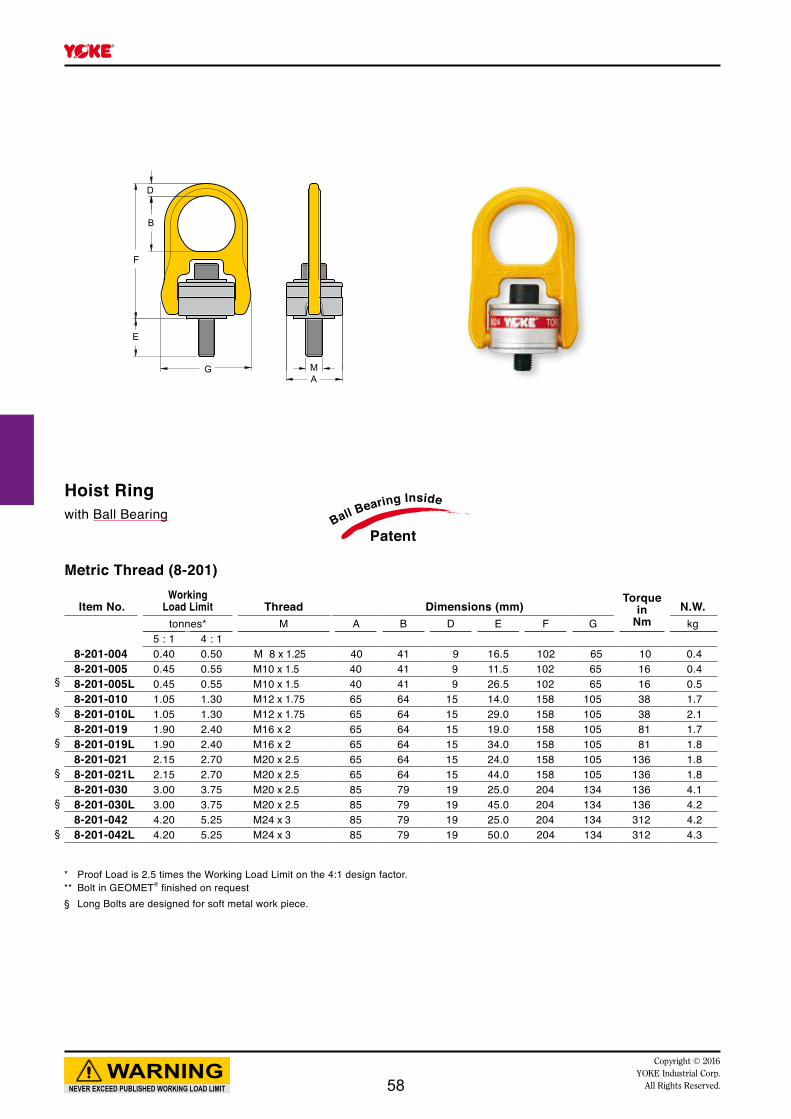
F
E
MA
G
D
B
Item No.Working
Load Limit Thread Dimensions (mm)Torque
inNm
N.W.tonnes* M A B D E F G kg
5 : 1 4 : 18-201-004 0.40 0.50 M 8 x 1.25 40 41 9 16.5 102 65 10 0.48-201-005 0.45 0.55 M10 x 1.5 40 41 9 11.5 102 65 16 0.48-201-005L 0.45 0.55 M10 x 1.5 40 41 9 26.5 102 65 16 0.5 8-201-010 1.05 1.30 M12 x 1.75 65 64 15 14.0 158 105 38 1.78-201-010L 1.05 1.30 M12 x 1.75 65 64 15 29.0 158 105 38 2.18-201-019 1.90 2.40 M16 x 2 65 64 15 19.0 158 105 81 1.78-201-019L 1.90 2.40 M16 x 2 65 64 15 34.0 158 105 81 1.88-201-021 2.15 2.70 M20 x 2.5 65 64 15 24.0 158 105 136 1.88-201-021L 2.15 2.70 M20 x 2.5 65 64 15 44.0 158 105 136 1.88-201-030 3.00 3.75 M20 x 2.5 85 79 19 25.0 204 134 136 4.18-201-030L 3.00 3.75 M20 x 2.5 85 79 19 45.0 204 134 136 4.28-201-042 4.20 5.25 M24 x 3 85 79 19 25.0 204 134 312 4.28-201-042L 4.20 5.25 M24 x 3 85 79 19 50.0 204 134 312 4.3
§
§
§
§
§
§
* Proof Load is 2.5 times the Working Load Limit on the 4:1 design factor.** Bolt in GEOMET® finished on request§ Long Bolts are designed for soft metal work piece.
NEVER EXCEED PUBLISHED WORKING LOAD LIMIT
WARNINGCopyright © 2016
YOKE Industrial Corp.All Rights Reserved.
PatentBall Bearing InsideHoist Ring
with Ball Bearing
Metric Thread (8-201)
58
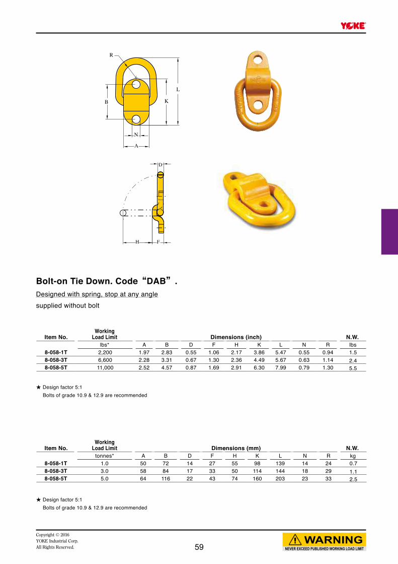
A B D F H K L N R8-058-1T 1.0 50 72 14 27 55 98 139 14 24 0.78-058-3T 3.0 58 84 17 33 50 114 144 18 29 1.18-058-5T 5.0 64 116 22 43 74 160 203 23 33 2.5
A B D F H K L N R8-058-1T 2,200 1.97 2.83 0.55 1.06 2.17 3.86 5.47 0.55 0.94 1.58-058-3T 6,600 2.28 3.31 0.67 1.30 2.36 4.49 5.67 0.63 1.14 2.48-058-5T 11,000 2.52 4.57 0.87 1.69 2.91 6.30 7.99 0.79 1.30 5.5
NEVER EXCEED PUBLISHED WORKING LOAD LIMIT
WARNINGCopyright © 2016 YOKE Industrial Corp.All Rights Reserved.
★ Design factor 5:1 Bolts of grade 10.9 & 12.9 are recommended
★ Design factor 5:1 Bolts of grade 10.9 & 12.9 are recommended
Item No.Working
Load Limit Dimensions (mm) N.W.tonnes* kg
Item No.Working
Load Limit Dimensions (inch) N.W.lbs* lbs
A
N
K
L
B
R
H F
D
Bolt-on Tie Down. Code“DAB”.Designed with spring, stop at any anglesupplied without bolt
59

L
W
A
Dd
NEVER EXCEED PUBLISHED WORKING LOAD LIMIT
WARNINGCopyright © 2016
YOKE Industrial Corp.All Rights Reserved.
Item No.Working
Load Limit
ForGrade 80
Chain Dimensions (mm) N.W.tonnes* mm A W D d min** L kg
8-098-06 1.12 6 6 37 28 17L min=2xd min
0.48-098-07 2.0 7,8 9 50 30 22 0.68-098-10 3.15 10 11 60 34.5 28 0.9
Item No.Working
Load Limit
ForGrade 80
Chain Dimensions (inch) N.W.lbs* inch A W D d min** L lbs
8-098-06 2100 7/32 0.24 1.46 1.10 0.67L min=2xd min
0.98-098-07 4500 1/4~5/16 0.35 1.97 1.18 0.87 1.38-098-10 7100 3/8 0.43 2.36 1.36 1.10 2.0
Plug-in Connector
★ Minimun Ultimate Load is 4 times the Working Load Limit.★ Proof Load is 2.5 times the Working Load Limit.
★ Minimun Ultimate Load is 4 times the Working Load Limit.★ Proof Load is 2.5 times the Working Load Limit.
60

Copyright © 2016YOKE Industrial Corp.All Rights Reserved.
Weld-on Lifting Points
61
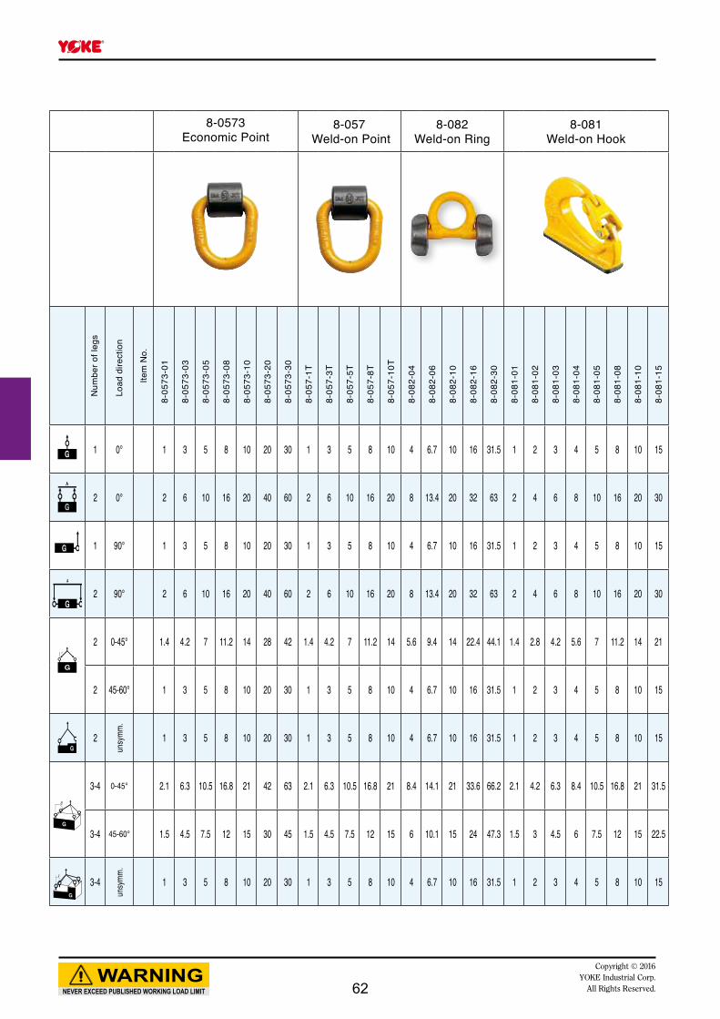
NEVER EXCEED PUBLISHED WORKING LOAD LIMIT
WARNINGCopyright © 2016
YOKE Industrial Corp.All Rights Reserved.
8-0573Economic Point
8-057 Weld-on Point
8-082Weld-on Ring
8-081Weld-on Hook
Num
ber o
f leg
s
Load
dire
ctio
n
Item
No.
1 0° 1 3 5 8 10 20 30 1 3 5 8 10 4 6.7 10 16 31.5 1 2 3 4 5 8 10 15
2 0° 2 6 10 16 20 40 60 2 6 10 16 20 8 13.4 20 32 63 2 4 6 8 10 16 20 30
1 90° 1 3 5 8 10 20 30 1 3 5 8 10 4 6.7 10 16 31.5 1 2 3 4 5 8 10 15
2 90° 2 6 10 16 20 40 60 2 6 10 16 20 8 13.4 20 32 63 2 4 6 8 10 16 20 30
2 0-45° 1.4 4.2 7 11.2 14 28 42 1.4 4.2 7 11.2 14 5.6 9.4 14 22.4 44.1 1.4 2.8 4.2 5.6 7 11.2 14 21
2 45-60° 1 3 5 8 10 20 30 1 3 5 8 10 4 6.7 10 16 31.5 1 2 3 4 5 8 10 15
2
unsy
mm.
1 3 5 8 10 20 30 1 3 5 8 10 4 6.7 10 16 31.5 1 2 3 4 5 8 10 15
3-4 0-45° 2.1 6.3 10.5 16.8 21 42 63 2.1 6.3 10.5 16.8 21 8.4 14.1 21 33.6 66.2 2.1 4.2 6.3 8.4 10.5 16.8 21 31.5
3-4 45-60° 1.5 4.5 7.5 12 15 30 45 1.5 4.5 7.5 12 15 6 10.1 15 24 47.3 1.5 3 4.5 6 7.5 12 15 22.5
3-4
unsy
mm.
1 3 5 8 10 20 30 1 3 5 8 10 4 6.7 10 16 31.5 1 2 3 4 5 8 10 15
8-05
73-0
1
8-05
73-0
3
8-05
73-0
5
8-05
73-0
8
8-05
73-1
0
8-05
73-2
0
8-05
73-3
0
8-05
7-1T
8-05
7-3T
8-05
7-5T
8-05
7-8T
8-05
7-10
T
8-08
2-04
8-08
2-06
8-08
2-10
8-08
2-16
8-08
2-30
8-08
1-01
8-08
1-02
8-08
1-03
8-08
1-04
8-08
1-05
8-08
1-08
8-08
1-10
8-08
1-15
62
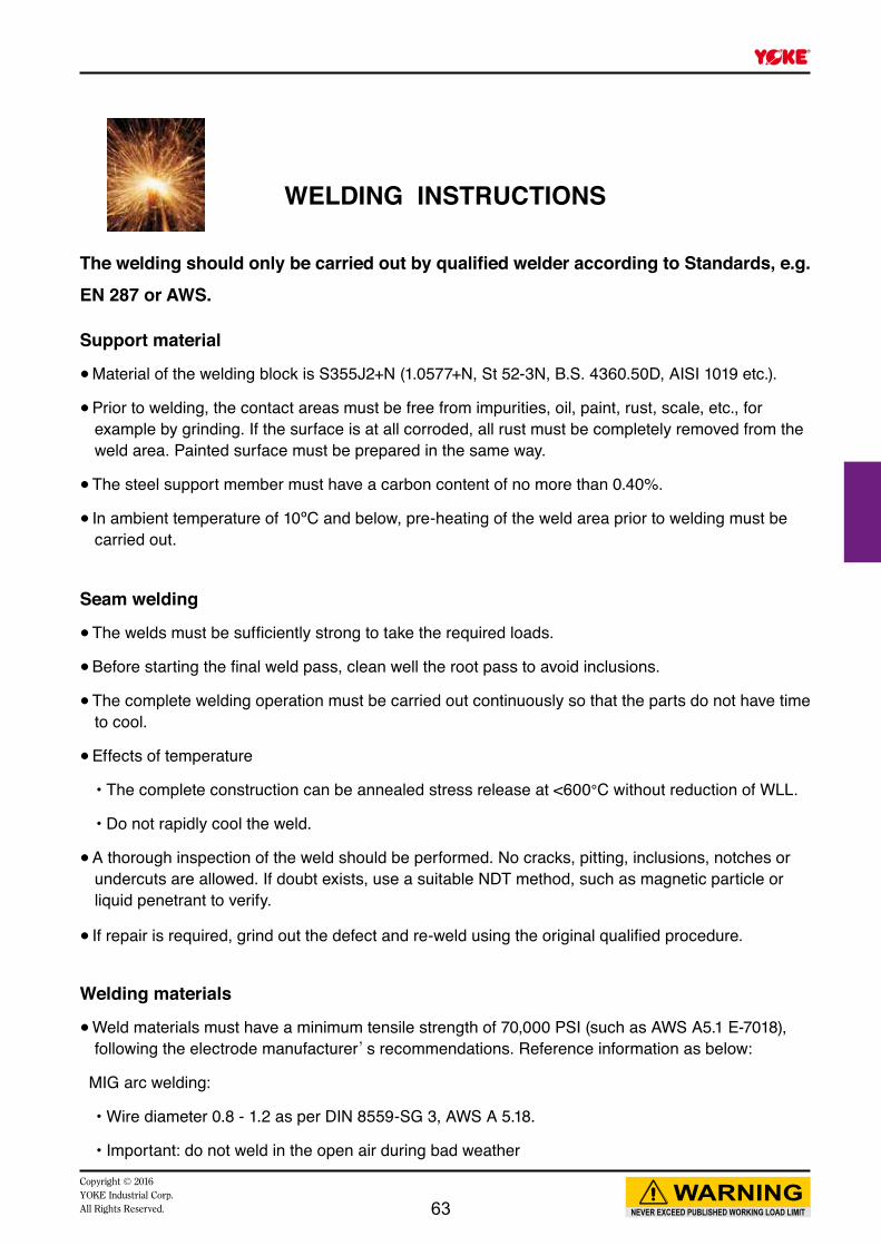
NEVER EXCEED PUBLISHED WORKING LOAD LIMIT
WARNINGCopyright © 2016 YOKE Industrial Corp.All Rights Reserved.
WELDING INSTRUCTIONS
The welding should only be carried out by qualified welder according to Standards, e.g. EN 287 or AWS.
Support material ● Material of the welding block is S355J2+N (1.0577+N, St 52-3N, B.S. 4360.50D, AISI 1019 etc.).
● Prior to welding, the contact areas must be free from impurities, oil, paint, rust, scale, etc., for example by grinding. If the surface is at all corroded, all rust must be completely removed from the weld area. Painted surface must be prepared in the same way.
● The steel support member must have a carbon content of no more than 0.40%.
● In ambient temperature of 10ºC and below, pre-heating of the weld area prior to welding must be carried out.
Seam welding ● The welds must be sufficiently strong to take the required loads.
● Before starting the final weld pass, clean well the root pass to avoid inclusions.
● The complete welding operation must be carried out continuously so that the parts do not have time to cool.
● Effects of temperature
• The complete construction can be annealed stress release at <600°C without reduction of WLL.
• Do not rapidly cool the weld.
● A thorough inspection of the weld should be performed. No cracks, pitting, inclusions, notches or undercuts are allowed. If doubt exists, use a suitable NDT method, such as magnetic particle or liquid penetrant to verify.
● If repair is required, grind out the defect and re-weld using the original qualified procedure.
Welding materials ● Weld materials must have a minimum tensile strength of 70,000 PSI (such as AWS A5.1 E-7018), following the electrode manufacturer’s recommendations. Reference information as below:
MIG arc welding:
• Wire diameter 0.8 - 1.2 as per DIN 8559-SG 3, AWS A 5.18.
• Important: do not weld in the open air during bad weather
63

A
W
MLT
H
P
F
Item No.Working
Load Limit Dimensions (mm) N.W. RepairKitstonnes* A F H L M P T W kg
8-081-01 1.0 7 25 27 72 6 18 17 95 0.6 8-P081-018-081-02 2.0 8 30 31 88 8 25 20 115 1.0 8-P081-028-081-03 3.0 9 35 30 107 10 28 23 133 1.4 8-P081-038-081-04 4.0 10 42 38 112 11 28 30 141 2.0 8-P081-048-081-05 5.0 12 44 46 133 13 30 31 167 3.0 8-P081-058-081-08 8.0 12 50 54 137 14 32 39 175 3.8 8-P081-088-081-10 10.0 13 56 56 168 16 44 42 222 6.3 8-P081-108-081-15 15.0 14 61 67 184 17 54 45 241 7.9 8-P081-15
NEVER EXCEED PUBLISHED WORKING LOAD LIMIT
WARNINGCopyright © 2016
YOKE Industrial Corp.All Rights Reserved.
Weld-on Hook. Code“YX”.
★ Design factor 5:1 YOKE recommends that the working load limit is reduced to meet any appropriate legislative requirements, if welding on
to an excavator. Please contact your YOKE distributors for further information.
★ Design factor 5:1 YOKE recommends that the working load limit is reduced to meet any appropriate legislative requirements, if welding on
to an excavator. Please contact your YOKE distributors for further information.
Item No.Working
Load Limit Dimensions (inch) N.W. RepairKitslbs* A F H L M P T W lbs
8-081-01 2,200 0.28 0.98 1.06 2.83 0.24 0.71 0.67 3.74 1.3 8-P081-018-081-02 4,400 0.31 1.18 1.22 3.46 0.31 0.98 0.79 4.53 2.2 8-P081-028-081-03 6,600 0.35 1.38 1.18 4.21 0.39 1.10 0.91 5.24 3.1 8-P081-038-081-04 8,800 0.39 1.65 1.50 4.41 0.43 1.10 1.18 5.55 4.4 8-P081-048-081-05 11,000 0.47 1.73 1.81 5.24 0.51 1.18 1.22 6.57 6.6 8-P081-058-081-08 17,600 0.47 1.97 2.13 5.39 0.55 1.26 1.54 6.89 8.4 8-P081-088-081-10 22,000 0.51 2.20 2.20 6.61 0.63 1.73 1.65 8.74 13.9 8-P081-108-081-15 33,000 0.55 2.40 2.64 7.24 0.67 2.13 1.77 9.49 17.4 8-P081-15
Repair Kits
64

Item No.Working
Load Limit Dimensions (mm) N.W.tonnes* D F H K L R W kg
8-0573-01 1.0 14 26 56 37 105 24 48 0.58-0573-03 3.0 17 31 63 48 112 29 54 0.98-0573-05 5.0 22 37 66 56 154 33 56 1.38-0573-08 8.0 26 47 88 68 169 34 55 2.48-0573-10 10.0 20 47 88 68 191 41 70 2.88-0573-20 20.0** 25 70 123 93 234 50 91 6.58-0573-30 30.0** 35 98 145 130 328 70 127 17.2
R
W
K
L
D
FH
180° Pivot
NEVER EXCEED PUBLISHED WORKING LOAD LIMIT
WARNINGCopyright © 2016 YOKE Industrial Corp.All Rights Reserved.
★ Design factor 5:1** Design factor 4:1
Economic PointEconomic Type without Spring Inside
Economic Type
65

R
W
K
L
D
FH
180° Pivot
Stop at Any Angle
Item No.Working
Load Limit Dimensions (inch) N.W.lbs* D F H K L R W lbs
8-057-1T 2,200 0.55 1.06 2.17 1.50 4.13 0.94 1.97 1.18-057-3T 6,600 0.67 1.34 2.36 1.89 4.41 1.14 2.28 1.88-057-5T 11,000 0.87 1.69 2.91 2.40 6.06 1.30 2.52 4.08-057-8T 17,000 1.05 2.12 3.22 2.87 6.65 1.33 2.40 5.78-057-10T 22,000 0.78 2.12 4.06 2.87 7.52 1.61 2.95 6.8
Item No.Working
Load Limit Dimensions (mm) N.W.tonnes* D F H K L R W kg
8-057-1T 1.0 14 27 55 38 105 24 50 0.58-057-3T 3.0 17 34 60 48 112 29 58 0.98-057-5T 5.0 22 43 74 61 154 33 64 1.38-057-8T 8.0 26 54 82 73 169 34 61 2.68-057-10T 10.0 20 54 103 73 191 41 75 3.1
NEVER EXCEED PUBLISHED WORKING LOAD LIMIT
WARNINGCopyright © 2016
YOKE Industrial Corp.All Rights Reserved.
★ Design factor 5:1
★ Design factor 5:1
Weld-on Point. Code“DAA”.Designed with spring, stop at any angle
66

NEVER EXCEED PUBLISHED WORKING LOAD LIMIT
WARNINGCopyright © 2016 YOKE Industrial Corp.All Rights Reserved.
B
A
L
180° Pivot
°
FE
b
a
M
D
C180° Pivot
Weld-on Ring
★ Design Factor 4:1
Item No.Working
Load Limit Dimensions (mm) N.W.tonnes* A B C D E F L M a° b kg
8-082-04 4 66 14 30 48 65 70 135 76 45 5 0.68-082-06 6.7 85 20 39 60 89 91 171 98 45 5 1.58-082-10 10 95 21 46 65 100 100 196 106 45 7 2.48-082-16 16 127 30 57 90 130 136 263 149 45 8 5.58-082-30 31.5 178 42 78 130 160 195 375 213 45 15 15.8
67

Copyright © 2016YOKE Industrial Corp.All Rights Reserved. 68

AB
C
D
KL
H
Item No.
Wire Line Size
WorkingLoad Limit Dimensions (inch) N.W.
inch Tons* B K L C A D H lbs8-301-0075 1/4 0.75 1.30 4.00 5.00 0.50 0.60 0.40 0.90 1.18-301-015 3/8 1.5 1.60 4.40 5.70 0.60 0.70 0.50 1.00 1.78-301-03 1/2 3 2.00 6.30 8.00 0.90 0.90 0.60 1.20 4.48-301-05 5/8 5 2.50 8.00 10.30 1.20 1.30 0.90 1.50 8.78-301-085 3/4 8.5 3.00 9.50 12.30 1.40 1.50 1.00 2.00 14.88-301-10 7/8 10 4.00 12.50 16.00 1.80 1.70 1.50 2.10 40.08-301-15 1 15 4.30 12.50 16.00 1.80 2.00 1.50 2.20 46.28-301-25 1 1/4 25 5.20 14.70 19.50 2.40 2.50 2.00 2.70 80.58-301-35 1 1/2 35 5.20 14.70 19.50 2.40 2.50 2.00 2.70 94.4
Item No.
Wire Line Size
WorkingLoad Limit Dimensions (mm) N.W.
mm Tons* B K L C A D H kg8-301-0075 6 0.75 32 103 126 12 15 10 22 0.58-301-015 10 1.5 40 112 144 16 18 11 26 0.88-301-03 13 3 51 159 203 23 23 16 31 2.08-301-05 16 5 64 200 262 31 32 22 37 4.08-301-085 19 8.5 76 242 312 35 37 25 50 6.78-301-10 22 10 102 317 408 46 42 38 53 18.28-301-15 25 15 108 317 408 46 48 38 56 21.08-301-25 32 25 132 374 495 61 62 51 69 36.58-301-35 38 35 132 374 495 61 62 51 69 42.9
NEVER EXCEED PUBLISHED WORKING LOAD LIMIT
WARNINGCopyright © 2016 YOKE Industrial Corp.All Rights Reserved.
★ Minimum Ultimate Load is 5 times the Working Load Limit. Maximun Proof Load is 2 times the Working Load Limit.
★ Minimum Ultimate Load is 5 times the Working Load Limit. Maximun Proof Load is 2 times the Working Load Limit.
Angular Contact Bearing Swivels - Bullet Style
● YOKE Swivels are manufactured using the highest grade of material available.
● YOKE Swivels are designed with a safety factor of 5:1.
● YOKE Swivels are available in sizes from 3/4 Tons to 35 Tons.
● YOKE Swivels are available for wire lines 1/4" to 1-1/2".
● YOKE Swivels are zinc plated for corrosion resistance and longer life.
● YOKE Swivels are manufactured with grease fittings for superior performance.
● YOKE Swivels are designed for low starting torque and high rotation speed.
● All Swivels parts are 100% magnaflux crack detected.
● 20,000 cycle fatigue rate to 1.5 times working load limit.
● All parts with batch number for quality certified and traceability.
69

K
A
B
CD
G
L
H
Item No.
Wire Line Size
WorkingLoad Limit Dimensions (inch) N.W.
inch Tons* A B C D G H K L lbs8-303-0075 1/4 0.75 0.60 1.30 0.50 0.40 0.20 0.90 4.10 5.00 1.18-303-015 3/8 1.5 0.70 1.60 0.80 0.50 0.30 1.00 4.40 6.00 2.08-303-03 1/2 3 0.90 2.00 1.00 0.80 0.40 1.30 6.20 8.20 5.18-303-05 5/8 5 1.30 2.50 1.20 0.90 0.60 1.50 8.00 10.30 9.78-303-085 3/4 8.5 1.60 3.00 1.30 1.20 0.60 2.10 10.00 12.60 16.88-303-10 7/8 10 1.70 4.00 1.90 1.50 1.00 2.10 12.40 16.20 43.08-303-15 1 15 1.90 4.30 2.00 1.50 1.00 2.20 12.40 16.50 47.88-303-25 1 1/4 25 2.40 5.20 2.60 2.00 1.20 2.80 14.70 20.00 87.08-303-35 1 1/2 35 2.40 5.20 2.60 2.00 1.20 2.80 14.70 20.00 102.0
Item No.
Wire Line Size
WorkingLoad Limit Dimensions (mm) N.W.
mm Tons* A B C D G H K L kg8-303-0075 6 0.75 15 32 13 10 6 22 103 128 0.58-303-015 10 1.5 18 40 20 13 8 26 112 152 0.98-303-03 13 3 23 51 25 19 10 32 158 208 2.38-303-05 16 5 32 64 31 22 14 37 200 261 4.48-303-085 19 8.5 40 76 34 30 14 54 252 320 7.68-303-10 22 10 42 102 48 38 25 54 316 412 19.58-303-15 25 15 48 108 52 38 25 57 316 420 21.78-303-25 32 25 62 132 65 51 30 70 374 503 39.58-303-35 38 35 62 132 65 51 30 70 374 503 46.2
NEVER EXCEED PUBLISHED WORKING LOAD LIMIT
WARNINGCopyright © 2016
YOKE Industrial Corp.All Rights Reserved.
● YOKE Swivels are manufactured using the highest grade of material available.
● YOKE Swivels are designed with a safety factor of 5:1.
● YOKE Swivels are available in sizes from 3/4 Tons to 35 Tons.
● YOKE Swivels are available for wire lines 1/4" to 1-1/2".
● YOKE Swivels are zinc plated for corrosion resistance and longer life.
● YOKE Swivels are manufactured with grease fittings for superior performance.
● YOKE Swivels are designed for low starting torque and high rotation speed.
● All Swivels parts are 100% magnaflux crack detected.
● 20,000 cycle fatigue rate to 1.5 times working load limit.
● All parts with batch number for quality certified and traceability.
Angular Contact Bearing Swivels - Jaw + Jaw
★ Minimum Ultimate Load is 5 times the Working Load Limit. Maximun Proof Load is 2 times the Working Load Limit.
★ Minimum Ultimate Load is 5 times the Working Load Limit. Maximun Proof Load is 2 times the Working Load Limit.
70

K
AB
D
L
H
G
IJ W
T
Item No.
Wire Line Size
WorkingLoad Limit Dimensions (inch) N.W.
inch Tons* A B D G H I J K L T W lbs8-304-0075 1/4 0.75 0.60 1.30 0.40 0.20 0.90 0.70 0.80 4.10 5.30 0.50 1.50 1.18-304-015 3/8 1.5 0.70 1.60 0.50 0.30 1.00 0.90 0.90 4.50 6.10 0.60 1.70 2.08-304-03 1/2 3 0.90 2.00 0.80 0.40 1.30 1.10 1.10 6.20 8.30 0.80 2.00 4.88-304-05 5/8 5 1.30 2.50 0.90 0.60 1.50 1.30 1.30 8.10 10.60 1.00 2.30 9.78-304-085 3/4 8.5 1.60 3.00 1.20 0.60 2.10 1.50 1.50 9.80 12.70 1.30 3.20 16.38-304-10 7/8 10 1.70 4.00 1.50 1.00 2.10 2.00 1.70 12.30 16.20 1.70 3.50 39.08-304-15 1 15 1.90 4.30 1.50 1.00 2.20 2.50 2.10 12.50 17.10 1.90 4.30 47.68-304-25 1 1/4 25 2.40 5.20 2.00 1.20 2.80 2.80 2.60 15.40 20.60 2.40 5.10 87.38-304-35 1 1/2 35 2.40 5.20 2.00 1.20 2.80 2.80 2.60 15.40 20.60 2.40 5.10 102.3
Item No.
Wire Line Size
WorkingLoad Limit Dimensions (mm) N.W.
mm Tons* A B D G H I J K L T W kg8-304-0075 6 0.75 15 32 10 6 22 18 19 103 134 12 37 0.58-304-015 10 1.5 18 40 13 7 26 22 23 115 156 15 43 0.98-304-03 13 3 23 51 19 10 32 28 27 158 211 20 51 2.28-304-05 16 5 32 64 22 14 37 33 33 205 269 26 59 4.48-304-085 19 8.5 40 76 30 14 54 38 37 250 322 32 82 7.48-304-10 22 10 42 102 38 25 54 52 44 312 412 42 90 17.58-304-15 25 15 48 108 38 25 57 64 54 317 434 49 110 21.68-304-25 32 25 62 132 51 30 70 70 66 390 524 60 130 39.78-304-35 32 35 62 132 51 30 70 70 66 390 524 60 130 46.4
NEVER EXCEED PUBLISHED WORKING LOAD LIMIT
WARNINGCopyright © 2016 YOKE Industrial Corp.All Rights Reserved.
Angular Contact Bearing Swivels - Jaw + Eye
● YOKE Swivels are manufactured using the highest grade of material available.
● YOKE Swivels are designed with a safety factor of 5:1.
● YOKE Swivels are available in sizes from 3/4 Tons to 35 Tons.
● YOKE Swivels are available for wire lines 1/4" to 1-1/2".
● YOKE Swivels are zinc plated for corrosion resistance and longer life.
● YOKE Swivels are manufactured with grease fittings for superior performance.
● YOKE Swivels are designed for low starting torque and high rotation speed.
● All Swivels parts are 100% magnaflux crack detected.
● 20,000 cycle fatigue rate to 1.5 times working load limit.
● All parts with batch number for quality certified and traceability.
★ Minimum Ultimate Load is 5 times the Working Load Limit. Maximun Proof Load is 2 times the Working Load Limit.
★ Minimum Ultimate Load is 5 times the Working Load Limit. Maximun Proof Load is 2 times the Working Load Limit.
71

I
A
K
T
JW
B G
D
L
H
Item No.
Wire Line Size
WorkingLoad Limit Dimensions (inch) N.W.
inch Tons* A B D G H I J K L T W lbs8-305-0075 1/4 0.75 0.60 1.30 0.40 0.20 0.90 0.70 0.80 4.06 5.28 0.50 1.50 1.18-305-015 3/8 1.5 0.70 1.60 0.50 0.30 1.00 0.90 0.90 4.53 6.14 0.60 1.70 2.08-305-03 1/2 3 0.90 2.00 0.80 0.40 1.30 1.10 1.10 6.22 8.31 0.80 2.00 4.88-305-05 5/8 5 1.30 2.50 0.90 0.60 1.50 1.30 1.30 8.07 10.60 1.00 2.30 9.78-305-085 3/4 8.5 1.60 3.00 1.20 0.60 2.10 1.50 1.50 9.84 12.68 1.30 3.20 16.48-305-10 7/8 10 1.70 4.00 1.50 1.00 2.10 2.00 1.70 12.28 16.22 1.70 3.50 39.68-305-15 1 15 1.90 4.30 1.50 1.00 2.20 2.50 2.10 12.50 17.10 1.90 4.30 46.78-305-25 1 1/4 25 2.40 5.20 2.00 1.20 2.80 2.80 2.60 15.35 20.63 2.40 5.10 88.08-305-35 1 1/2 35 2.40 5.20 2.00 1.20 2.80 2.80 2.60 15.35 20.63 2.40 5.10 103.0
Item No.
Wire Line Size
WorkingLoad Limit Dimensions (mm) N.W.
mm Tons* A B D G H I J K L T W kg8-305-0075 6 0.75 15 32 10 6 22 18 19 103 134 12 37 0.58-305-015 10 1.5 18 40 13 7 26 22 23 115 156 15 43 0.98-305-03 13 3 23 51 19 10 32 28 27 158 211 20 51 2.28-305-05 16 5 32 64 22 14 37 33 33 204 268 26 59 4.48-305-085 19 8.5 40 76 30 14 54 38 37 250 322 32 82 7.48-305-10 22 10 42 102 38 25 54 52 44 313 413 42 90 18.08-305-15 25 15 48 108 38 25 57 64 54 314 430 49 110 21.28-305-25 32 25 62 132 51 30 70 70 66 391 526 60 130 40.0 8-305-35 38 35 62 132 51 30 70 70 66 391 526 60 130 46.7
NEVER EXCEED PUBLISHED WORKING LOAD LIMIT
WARNINGCopyright © 2016
YOKE Industrial Corp.All Rights Reserved.
Angular Contact Bearing Swivels - Eye + Jaw
● YOKE Swivels are manufactured using the highest grade of material available.
● YOKE Swivels are designed with a safety factor of 5:1.
● YOKE Swivels are available in sizes from 3/4 Tons to 35 Tons.
● YOKE Swivels are available for wire lines 1/4" to 1-1/2".
● YOKE Swivels are zinc plated for corrosion resistance and longer life.
● YOKE Swivels are manufactured with grease fittings for superior performance.
● YOKE Swivels are designed for low starting torque and high rotation speed.
● All Swivels parts are 100% magnaflux crack detected.
● 20,000 cycle fatigue rate to 1.5 times working load limit.
● All parts with batch number for quality certified and traceability.
★ Minimum Ultimate Load is 5 times the Working Load Limit. Maximun Proof Load is 2 times the Working Load Limit.
★ Minimum Ultimate Load is 5 times the Working Load Limit. Maximun Proof Load is 2 times the Working Load Limit.
72

B
K L
T
W JI
Item No.
Wire Line Size
WorkingLoad Limit Dimensions (inch) N.W.
inch Tons* B I J K L T W lbs8-306-0075 1/4 0.75 1.30 0.70 0.70 4.10 5.50 0.50 1.50 1.18-306-015 3/8 1.50 1.60 0.90 0.90 4.60 6.30 0.60 1.70 2.08-306-03 1/2 3 2.00 1.10 1.10 6.20 8.40 0.80 2.00 4.68-306-05 5/8 5 2.50 1.30 1.30 8.30 10.90 1.00 2.30 9.78-306-085 3/4 8.50 3.00 1.50 1.50 9.80 12.80 1.30 3.20 16.18-306-10 7/8 10 4.00 2.10 2.00 12.20 16.30 1.70 3.50 37.48-306-15 1 15 4.30 2.50 2.50 12.40 17.40 1.90 4.30 46.38-306-25 1 1/4 25 5.20 2.80 2.80 16.00 21.50 2.40 5.10 86.08-306-35 1 1/2 35 5.20 2.80 2.80 16.00 21.50 2.40 5.10 101.0
Item No.
Wire Line Size
WorkingLoad Limit Dimensions (mm) N.W.
mm Tons* B I J K L T W kg8-306-0075 6 0.75 32 18 19 103 139 12 37 0.58-306-015 10 1.50 40 22 23 117 160 15 43 0.98-306-03 13 3 51 28 27 158 214 20 51 2.18-306-05 16 5 64 33 33 210 276 26 59 4.48-306-085 19 8.50 76 38 37 249 325 32 82 7.38-306-10 22 10 102 52 44 310 413 42 90 17.08-306-15 25 15 108 64 54 316 443 49 110 21.08-306-25 32 25 132 70 66 407 547 60 130 39.08-306-35 38 35 132 70 66 407 547 60 130 45.8
NEVER EXCEED PUBLISHED WORKING LOAD LIMIT
WARNINGCopyright © 2016 YOKE Industrial Corp.All Rights Reserved.
Angular Contact Bearing Swivels - Eye + Eye
● YOKE Swivels are manufactured using the highest grade of material available.
● YOKE Swivels are designed with a safety factor of 5:1.
● YOKE Swivels are available in sizes from 3/4 Tons to 35 Tons.
● YOKE Swivels are available for wire lines 1/4" to 1-1/2".
● YOKE Swivels are zinc plated for corrosion resistance and longer life.
● YOKE Swivels are manufactured with grease fittings for superior performance.
● YOKE Swivels are designed for low starting torque and high rotation speed.
● All Swivels parts are 100% magnaflux crack detected.
● 20,000 cycle fatigue rate to 1.5 times working load limit.
● All parts with batch number for quality certified and traceability.
★ Minimum Ultimate Load is 5 times the Working Load Limit. Maximun Proof Load is 2 times the Working Load Limit.
★ Minimum Ultimate Load is 5 times the Working Load Limit. Maximun Proof Load is 2 times the Working Load Limit.
73

K
I
W
T B
R
G
P
Item No.
Wire Line Size
WorkingLoad Limit Dimensions (mm) N.W.
mm Tons* B G I K P R T W kg8-307-0075 6 0.75 32 80 18 157 25 21 10 40 0.78-307-015 10 1.5 40 102 22 185 30 29 15 48 1.48-307-03 13 3 51 130 27 243 36 36 22 53 3.28-307-05 16 5 64 166 33 316 43 47 26 70 6.58-307-085 19 8.5 76 221 37 381 62 66 32 87 13.38-307-10 22 10 102 277 44 467 81 76 42 106 25.98-307-15 25 15 108 277 54 485 81 76 49 124 28.98-307-25 32 25 132 353 66 583 83 92 59 145 54.5
Item No.
Wire Line Size
WorkingLoad Limit Dimensions (inch) N.W.
inch Tons* B G I K P R T W lbs8-307-0075 1/4 0.75 1.30 3.15 0.71 6.20 1.00 0.83 0.39 1.57 1.58-307-015 3/8 1.5 1.60 4.02 0.87 7.30 1.20 1.14 0.59 1.92 3.18-307-03 1/2 3 2.00 5.13 1.06 9.60 1.40 1.42 0.87 2.09 7.08-307-05 5/8 5 2.50 6.54 1.29 12.44 1.70 1.85 1.02 2.76 14.38-307-085 3/4 8.5 3.00 8.69 1.46 15.00 2.40 2.60 1.26 3.43 29.38-307-10 7/8 10 4.00 10.91 3.19 18.38 3.20 3.00 1.65 4.17 57.08-307-15 1 15 4.30 10.91 3.19 19.10 3.20 3.00 1.93 4.88 63.68-307-25 1 1/4 25 5.20 13.89 3.27 22.95 3.30 3.62 2.32 5.71 119.9
NEVER EXCEED PUBLISHED WORKING LOAD LIMIT
WARNINGCopyright © 2016
YOKE Industrial Corp.All Rights Reserved.
★ Minimum Ultimate Load is 5 times the Working Load Limit. Maximun Proof Load is 2 times the Working Load Limit.
Angular Contact Bearing Swivels - Eye + Hook
● YOKE Swivels are manufactured using the highest grade of material available.
● YOKE Swivels are designed with a safety factor of 5:1.
● YOKE Swivels are available in sizes from 3/4 Tons to 35 Tons.
● YOKE Swivels are available for wire lines 1/4" to 1-1/4".
● YOKE Swivels are zinc plated for corrosion resistance and longer life.
● YOKE Swivels are manufactured with grease fittings for superior performance.
● YOKE Swivels are designed for low starting torque and high rotation speed.
● All Swivels parts are 100% magnaflux crack detected.
● 20,000 cycle fatigue rate to 1.5 times working load limit.
● All parts with batch number for quality certified and traceability.
★ Minimum Ultimate Load is 5 times the Working Load Limit. Maximun Proof Load is 2 times the Working Load Limit.
74

K
A
DH
C B
R
G
P
Item No.
Wire Line Size
WorkingLoad Limit Dimensions (inch) N.W.
inch Tons* A B C D G H K P R lbs8-308-0075 1/4 0.75 0.40 1.30 0.50 0.40 3.15 0.90 5.48 1.00 0.83 1.58-308-015 3/8 1.5 0.50 1.60 0.80 0.50 4.02 1.00 6.33 1.20 1.14 3.38-308-03 1/2 3 0.75 2.00 0.91 0.75 5.13 1.30 8.66 1.40 1.42 7.38-308-05 5/8 5 0.87 2.50 1.20 0.87 6.54 1.50 10.99 1.70 1.85 14.18-308-085 3/4 8.5 1.18 3.00 1.37 1.18 8.69 1.97 13.58 2.40 2.60 29.58-308-10 7/8 10 1.50 4.00 1.89 1.50 10.91 2.10 16.49 3.20 3.00 60.08-308-15 1 15 1.50 4.30 2.02 1.50 10.91 2.20 16.57 3.20 3.00 63.78-308-25 1 1/4 25 2.00 5.20 2.56 2.00 13.89 2.74 19.53 3.30 3.62 124.5
Item No.
Wire Line Size
WorkingLoad Limit Dimensions (mm) N.W.
mm Tons* A B C D G H K P R kg8-308-0075 6 0.75 15 32 13 10 80 22 139 25 21 0.78-308-015 10 1.5 18 40 20 13 102 26 161 30 29 1.58-308-03 13 3 23 51 23 19 130 32 220 36 36 3.38-308-05 16 5 32 64 31 22 166 37 279 43 47 6.48-308-085 19 8.5 37 76 35 30 221 50 335 62 66 13.48-308-10 22 10 42 102 48 38 277 54 419 81 76 27.28-308-15 25 15 48 108 52 38 277 56 421 81 76 28.98-308-25 32 25 62 132 65 51 353 69 496 83 92 56.6
NEVER EXCEED PUBLISHED WORKING LOAD LIMIT
WARNINGCopyright © 2016 YOKE Industrial Corp.All Rights Reserved.
★ Minimum Ultimate Load is 5 times the Working Load Limit. Maximun Proof Load is 2 times the Working Load Limit.
★ Minimum Ultimate Load is 5 times the Working Load Limit. Maximun Proof Load is 2 times the Working Load Limit.
Angular Contact Bearing Swivels - Jaw + Hook
● YOKE Swivels are manufactured using the highest grade of material available.
● YOKE Swivels are designed with a safety factor of 5:1.
● YOKE Swivels are available in sizes from 3/4 Tons to 35 Tons.
● YOKE Swivels are available for wire lines 1/4" to 1-1/4".
● YOKE Swivels are zinc plated for corrosion resistance and longer life.
● YOKE Swivels are manufactured with grease fittings for superior performance.
● YOKE Swivels are designed for low starting torque and high rotation speed.
● All Swivels parts are 100% magnaflux crack detected.
● 20,000 cycle fatigue rate to 1.5 times working load limit.
● All parts with batch number for quality certified and traceability.
75

Copyright © 2016YOKE Industrial Corp.All Rights Reserved. 76

d min**
D
C
P
P1
R
H
G
T
L
NEVER EXCEED PUBLISHED WORKING LOAD LIMIT
WARNINGCopyright © 2016 YOKE Industrial Corp.All Rights Reserved.
● YOKE alloy shank hoist hook are manufactured from the finest quality alloy steel.
● YOKE shank hoist hook are quenched and tempered.
● 20,000 cycle fatigue rate to 1.5 times working load limit.
● All shank hoist hooks are 100% magnaflux crack detected.
● All parts with batch number for quality certified and traceability.
● YOKE Shank Hoist Hooks are proof tested to 2 times the working load limit..
● YOKE Shank Hoist Hooks are supplied without threads
● YOKE Shank Hoist Hooks are Predrilled to accept a YOKE latch kits.
● YOKE Shank Hoist Hooks are supplied with certification for each hook.
Alloy Shank Hoist HookSelf Colored
★ Minimum Ultimate Load is 5 times the Working Load Limit. Maximun Proof Load is 2 times the Working Load Limit. **d min.:After machining the shank, proof loading must be carried out.*S.C.=Self Colored
★ Minimum Ultimate Load is 5 times the Working Load Limit. Maximun Proof Load is 2 times the Working Load Limit. **d min.:After machining the shank, proof loading must be carried out.*S.C.=Self Colored
Item No.
WorkingLoad Limit
Hook Feature
CodeDimensions (inch) N.W.
with latch without latch tonnes* C D d min** G H L P P1 R T lbs8-171.SC-01 8-171.SC/0-01 1 AA 0.97 0.79 0.53 3.07 0.75 5.39 1.02 0.87 2.00 0.63 0.98-171.SC-015 8-171.SC/0-015 1.5 BB 0.97 0.66 0.62 3.15 0.87 5.98 0.95 0.75 2.45 0.71 1.38-171.SC-02 8-171.SC/0-02 2 CC 1.03 0.72 0.66 3.58 1.00 6.38 1.06 0.79 2.56 0.88 1.88-171.SC-03 8-171.SC/0-03 3 DD 1.16 0.88 0.81 4.02 1.18 7.72 1.22 0.98 2.91 0.94 2.68-171.SC-05 8-171.SC/0-05 5 EE 1.53 1.26 1.03 5.12 1.46 9.45 1.42 1.22 3.50 1.31 5.18-171.SC-07 8-171.SC/0-07 7 FF 1.94 1.41 1.27 6.54 1.82 11.18 1.77 1.54 3.89 1.66 9.28-171.SC-11 8-171.SC/0-11 11 GG 2.46 1.81 1.52 7.72 2.28 12.91 2.40 2.24 4.41 1.88 15.48-171.SC-15 8-171.SC/0-15 15 HH 2.59 2.00 1.75 8.70 2.60 13.54 2.83 2.44 4.53 2.19 20.98-171.SC-22 8-171.SC/0-22 22 JJ 2.81 2.56 2.00 10.91 3.01 16.97 3.39 3.19 5.91 2.69 41.88-171.SC-30 8-171.SC/0-30 30 KK 3.44 3.12 2.50 13.90 3.62 23.07 3.50 3.27 10.00 3.00 74.8
Item No.
WorkingLoad Limit
Hook Feature
CodeDimensions (mm) N.W.
with latch without latch tonnes* C D d min** G H L P P1 R T kg8-171.SC-01 8-171.SC/0-01 1 AA 25 20 13 78 19 137 25 26 51 16 0.48-171.SC-015 8-171.SC/0-015 1.5 BB 25 23 15 80 22 152 24 27 62 18 0.68-171.SC-02 8-171.SC/0-02 2 CC 26 26 16 91 25 162 24 27 65 22 0.88-171.SC-03 8-171.SC/0-03 3 DD 29 29 20 102 30 196 28 31 74 24 1.28-171.SC-05 8-171.SC/0-05 5 EE 38 32 26 130 37 240 35 37 89 33 2.38-171.SC-07 8-171.SC/0-07 7 FF 49 39 32 166 46 284 43 46 99 42 4.28-171.SC-11 8-171.SC/0-11 11 GG 62 45 38 196 58 328 61 64 112 48 7.08-171.SC-15 8-171.SC/0-15 15 HH 65 51 44 221 66 344 72 75 115 56 9.58-171.SC-22 8-171.SC/0-22 22 JJ 71 67 50 277 77 431 92 95 150 68 19.08-171.SC-30 8-171.SC/0-30 30 KK 87 70 63 353 92 586 89 93 254 76 34.0
77

R
C
P
P1
H
G
T
L
d min**
D
Item No.
WorkingLoad Limit
Hook Feature
CodeDimensions (mm) N.W.
with latch without latch tonnes* C D d min** G H L P P1 R T kg8-191.SC-0075 8-191.SC/0-0075 0.75 AA 25 20 13 78 19 137 25 26 51 16 0.48-191.SC-01 8-191.SC/0-01 1 BB 25 23 15 80 22 152 24 27 62 18 0.68-191.SC-015 8-191.SC/0-015 1.5 CC 26 26 16 91 25 162 24 27 65 22 0.88-191.SC-02 8-191.SC/0-02 2 DD 29 29 20 102 30 196 28 31 74 24 1.28-191.SC-03 8-191.SC/0-03 3 EE 38 32 26 130 37 240 35 37 89 33 2.38-191.SC-05 8-191.SC/0-05 5 FF 49 38 32 166 46 284 43 46 99 42 4.38-191.SC-075 8-191.SC/0-075 7.5 GG 62 45 38 196 58 328 61 64 112 48 7.08-191.SC-10 8-191.SC/0-10 10 HH 65 51 44 221 66 344 72 75 115 56 9.58-191.SC-15 8-191.SC/0-15 15 JJ 71 67 50 277 77 431 92 95 150 68 18.58-191.SC-20 8-191.SC/0-20 20 KK 87 70 63 353 92 586 89 93 254 76 34.2
Item No.
WorkingLoad Limit
Hook Feature
CodeDimensions (inch) N.W.
with latch without latch tonnes* C D d min** G H L P P1 R T lbs8-191.SC-0075 8-191.SC/0-0075 0.75 AA 0.97 0.79 0.53 3.07 0.75 5.39 0.98 1.02 2.00 0.63 0.98-191.SC-01 8-191.SC/0-01 1 BB 0.97 0.66 0.62 3.15 0.87 5.98 0.94 1.06 2.45 0.71 1.38-191.SC-015 8-191.SC/0-015 1.5 CC 1.03 0.72 0.66 3.58 1.00 6.38 0.94 1.06 2.56 0.88 1.88-191.SC-02 8-191.SC/0-02 2 DD 1.16 0.88 0.81 4.02 1.18 7.72 1.16 1.22 2.91 0.94 2.68-191.SC-03 8-191.SC/0-03 3 EE 1.53 1.26 1.03 5.12 1.46 9.45 1.38 1.46 3.50 1.31 5.18-191.SC-05 8-191.SC/0-05 5 FF 1.94 1.41 1.27 6.54 1.82 11.18 1.69 1.81 3.89 1.66 9.58-191.SC-075 8-191.SC/0-075 7.5 GG 2.46 1.81 1.52 7.72 2.28 12.91 2.40 2.51 4.41 1.88 15.48-191.SC-10 8-191.SC/0-10 10 HH 2.59 2.00 1.75 8.70 2.60 13.54 2.83 2.95 4.53 2.19 20.98-191.SC-15 8-191.SC/0-15 15 JJ 2.81 2.56 2.00 10.91 3.01 16.97 3.63 3.74 5.91 2.69 40.78-191.SC-20 8-191.SC/0-20 20 KK 3.44 3.12 2.50 13.90 3.62 23.07 3.50 3.66 10.00 3.00 75.2
NEVER EXCEED PUBLISHED WORKING LOAD LIMIT
WARNINGCopyright © 2016
YOKE Industrial Corp.All Rights Reserved.
● YOKE carbon shank hoist hook are manufactured from the finest quality carbon steel.
● YOKE shank hoist hook are quenched and tempered.
● 20,000 cycle fatigue rate to 1.5 times working load limit.
● All shank hoist hooks are 100% magnaflux crack detected.
● All parts with batch number for quality certified and traceability.
● YOKE Shank Hoist Hooks are proof tested to 2 times the working load limit.
● YOKE Shank Hoist Hooks are supplied without threads.
● YOKE Shank Hoist Hooks are Predrilled to accept a YOKE latch kits.
● YOKE Shank Hoist Hooks are supplied with certification for each hook.
Carbon Shank Hoist HookSelf Colored
★ Minimum Ultimate Load is 5 times the Working Load Limit. Maximun Proof Load is 2 times the Working Load Limit. **d min.:After machining the shank, proof loading must be carried out.*S.C.=Self Colored
★ Minimum Ultimate Load is 5 times the Working Load Limit. Maximun Proof Load is 2 times the Working Load Limit. **d min.:After machining the shank, proof loading must be carried out.*S.C.=Self Colored
78

A
K
T
P1
P
D
d
H
Item No.Working
Load Limit
G100 Working
Load LimitHook
FeatureCode
Dimensions (inch) N.W.with latch without latch tonnes* A D d H K P P1 T lbs
5 : 1 4 : 18-173-01 8-173/0-01 1 - AA 0.91 0.87 0.39 0.75 3.27 1.02 0.87 0.59 0.78-173-015 8-173/0-015 1.5 1.4 BB 0.91 0.75 0.43 0.83 3.74 1.02 0.75 0.67 0.98-173-02 8-173/0-02 2 2.5 CC 1.14 0.79 0.51 1.02 4.17 1.10 0.79 0.83 1.58-173-03 8-173/0-03 3 4 DD 1.26 0.98 0.59 1.14 4.80 1.22 0.98 0.95 2.08-173-05 8-173/0-05 5 6.7 EE 1.57 1.22 0.71 1.46 5.87 1.45 1.22 1.22 4.48-173-07 8-173/0-07 7 10 FF 2.00 1.54 0.95 1.85 7.56 1.81 1.54 1.46 8.88-173-11 8-173/0-11 11 16 GG 2.44 2.24 1.10 2.28 9.13 2.40 2.24 1.89 15.48-173-15 8-173/0-15 15 19 HH 2.84 2.44 1.26 2.60 10.10 2.68 2.44 2.20 20.78-173-22 8-173/0-22 22 26.5 JJ 3.54 3.19 1.57 3.00 12.50 3.62 3.19 2.68 41.18-173-30 8-173/0-30 30 - KK 3.54 3.27 1.77 3.66 14.10 3.50 3.27 2.99 68.9
Item No.Working
Load Limit
G100 Working
Load LimitHook
FeatureCode
Dimensions (mm) N.W.with latch without latch tonnes* A D d H K P P1 T kg
5 : 1 4 : 18-173-01 8-173/0-01 1 - AA 23 22 10 19 83 26 22 15 0.38-173-015 8-173/0-015 1.5 1.4 BB 23 19 11 21 95 26 19 17 0.48-173-02 8-173/0-02 2 2.5 CC 29 20 13 26 106 28 20 21 0.78-173-03 8-173/0-03 3 4 DD 32 25 15 29 122 31 25 24 0.98-173-05 8-173/0-05 5 6.7 EE 40 31 18 37 149 37 31 31 2.08-173-07 8-173/0-07 7 10 FF 51 39 24 47 192 46 39 37 4.08-173-11 8-173/0-11 11 16 GG 62 57 28 58 232 61 57 48 7.08-173-15 8-173/0-15 15 19 HH 72 62 32 66 256 68 62 56 9.48-173-22 8-173/0-22 22 26.5 JJ 90 81 40 76 318 92 81 68 18.78-173-30 8-173/0-30 30 - KK 90 83 45 93 357 89 83 76 31.3
NEVER EXCEED PUBLISHED WORKING LOAD LIMIT
WARNINGCopyright © 2016 YOKE Industrial Corp.All Rights Reserved.
● YOKE alloy eye hoist hook are manufactured from the finest quality alloy steel.
● YOKE eye hoist hook are quenched and tempered.
● 20,000 cycle fatigue rated to 1.5 times of 4:1 WLL, Hook Code AA and KK to 1.5 times of 5:1 WLL.
● All eye hoist hooks are 100% magnaflux crack detected.
● All parts with batch number for quality certified and traceability.
● YOKE Eye Hoist Hooks are proof tested to 2.5 times of 4:1 WLL, Hook Code AA and KK to 2 times of 5:1 WLL.
● YOKE Eye Hoist Hooks are Predrilled to accept a YOKE latch kits.
● YOKE Eye Hoist Hooks are supplied with certification.
Alloy Eye Hoist Hook
★ Hook Code BB to JJ also categorized as G100 components.★ Hook Code BB to JJ proof tested to 2.5 times of 4:1 WLL as G100 components.★ Hook Code AA and KK proof tested to 2 times of 5:1 WLL.
★ Hook Code BB to JJ also categorized as G100 components.★ Hook Code BB to JJ proof tested to 2.5 times of 4:1 WLL as G100 components.★ Hook Code AA and KK proof tested to 2 times of 5:1 WLL.
79
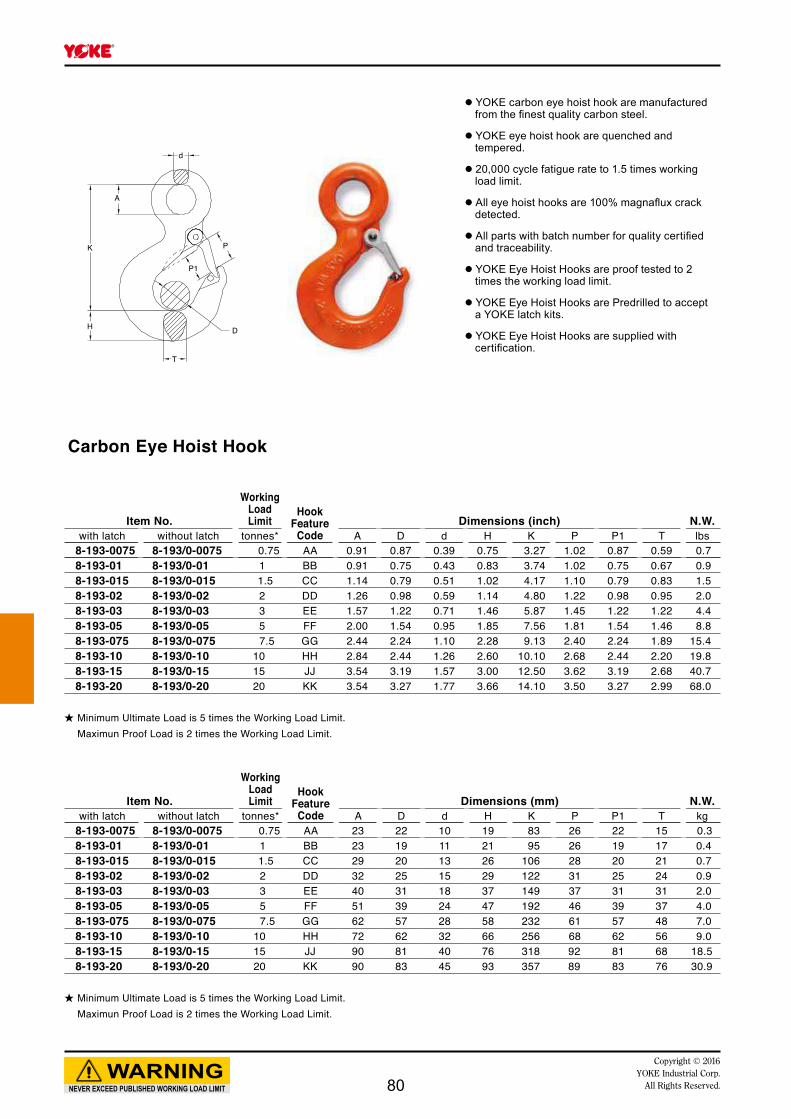
A
K
T
P1
P
D
d
H
NEVER EXCEED PUBLISHED WORKING LOAD LIMIT
WARNINGCopyright © 2016
YOKE Industrial Corp.All Rights Reserved.
● YOKE carbon eye hoist hook are manufactured from the finest quality carbon steel.
● YOKE eye hoist hook are quenched and tempered.
● 20,000 cycle fatigue rate to 1.5 times working load limit.
● All eye hoist hooks are 100% magnaflux crack detected.
● All parts with batch number for quality certified and traceability.
● YOKE Eye Hoist Hooks are proof tested to 2 times the working load limit.
● YOKE Eye Hoist Hooks are Predrilled to accept a YOKE latch kits.
● YOKE Eye Hoist Hooks are supplied with certification.
Carbon Eye Hoist Hook
★ Minimum Ultimate Load is 5 times the Working Load Limit. Maximun Proof Load is 2 times the Working Load Limit.
★ Minimum Ultimate Load is 5 times the Working Load Limit. Maximun Proof Load is 2 times the Working Load Limit.
Item No.
WorkingLoad Limit
Hook Feature
CodeDimensions (mm) N.W.
with latch without latch tonnes* A D d H K P P1 T kg8-193-0075 8-193/0-0075 0.75 AA 23 22 10 19 83 26 22 15 0.38-193-01 8-193/0-01 1 BB 23 19 11 21 95 26 19 17 0.48-193-015 8-193/0-015 1.5 CC 29 20 13 26 106 28 20 21 0.78-193-02 8-193/0-02 2 DD 32 25 15 29 122 31 25 24 0.98-193-03 8-193/0-03 3 EE 40 31 18 37 149 37 31 31 2.08-193-05 8-193/0-05 5 FF 51 39 24 47 192 46 39 37 4.08-193-075 8-193/0-075 7.5 GG 62 57 28 58 232 61 57 48 7.08-193-10 8-193/0-10 10 HH 72 62 32 66 256 68 62 56 9.08-193-15 8-193/0-15 15 JJ 90 81 40 76 318 92 81 68 18.58-193-20 8-193/0-20 20 KK 90 83 45 93 357 89 83 76 30.9
Item No.
WorkingLoad Limit
Hook Feature
CodeDimensions (inch) N.W.
with latch without latch tonnes* A D d H K P P1 T lbs8-193-0075 8-193/0-0075 0.75 AA 0.91 0.87 0.39 0.75 3.27 1.02 0.87 0.59 0.78-193-01 8-193/0-01 1 BB 0.91 0.75 0.43 0.83 3.74 1.02 0.75 0.67 0.98-193-015 8-193/0-015 1.5 CC 1.14 0.79 0.51 1.02 4.17 1.10 0.79 0.83 1.58-193-02 8-193/0-02 2 DD 1.26 0.98 0.59 1.14 4.80 1.22 0.98 0.95 2.08-193-03 8-193/0-03 3 EE 1.57 1.22 0.71 1.46 5.87 1.45 1.22 1.22 4.48-193-05 8-193/0-05 5 FF 2.00 1.54 0.95 1.85 7.56 1.81 1.54 1.46 8.88-193-075 8-193/0-075 7.5 GG 2.44 2.24 1.10 2.28 9.13 2.40 2.24 1.89 15.48-193-10 8-193/0-10 10 HH 2.84 2.44 1.26 2.60 10.10 2.68 2.44 2.20 19.88-193-15 8-193/0-15 15 JJ 3.54 3.19 1.57 3.00 12.50 3.62 3.19 2.68 40.78-193-20 8-193/0-20 20 KK 3.54 3.27 1.77 3.66 14.10 3.50 3.27 2.99 68.0
80

B
AD
C
PP1
K
H
GT
L
NEVER EXCEED PUBLISHED WORKING LOAD LIMIT
WARNINGCopyright © 2016 YOKE Industrial Corp.All Rights Reserved.
● YOKE alloy swivel hoist hook are manufactured from the finest quality alloy steel.
● YOKE swivel hoist hook are quenched and tempered.
● 20,000 cycle fatigue rated to 1.5 times of 4:1 WLL, Hook Code AA and KK to 1.5 times of 5:1 WLL.
● All swivel hoist hooks are 100% magnaflux crack detected.
● All parts with batch number for quality certified and traceability.
● YOKE Swivel Hoist Hooks are proof tested to 2.5 times of 4:1 WLL. Hook Code AA and KK to 2 times of 5:1 WLL.
● YOKE Swivel Hoist Hooks are Predrilled to accept a YOKE latch kits.
Alloy Swivel Hoist Hookwith Brass Washer
Item No.
WorkingLoad Limit
G100Working
Load Limit
Hook Feature
CodeDimensions (mm) N.W.
with latch without latch tonnes* A B C D G H K L P P1 T kg5 : 1 4 : 1
8-175-01 8-175/0-01 1 - AA 32 23 25 12 78 19 123 154 26 22 16 0.68-175-015 8-175/0-015 1.5 1.4 BB 32 23 25 12 80 21 126 158 24 19 18 0.78-175-02 8-175/0-02 2 2.5 CC 36 29 26 13 91 25 143 181 27 20 22 1.08-175-03 8-175/0-03 3 4 DD 41 35 29 16 102 29 172 217 28 25 24 1.58-175-05 8-175/0-05 5 6.7 EE 46 44 38 21 130 36 211 269 36 31 31 3.28-175-07 8-175/0-07 7 10 FF 61 51 49 23 166 46 258 328 45 39 42 5.78-175-11 8-175/0-11 11 16 GG 74 82 62 25 196 58 326 409 61 57 48 9.58-175-15 8-175/0-15 15 19 HH 97 96 65 33 221 64 372 471 72 62 56 16.58-175-22 8-175/0-22 22 26.5 JJ 123 116 71 51 277 76 469 599 86 81 68 33.48-175-30 8-175/0-30 30 - KK 123 116 87 51 353 93 503 651 89 83 76 45.9
Item No.
WorkingLoad Limit
G100Working
Load Limit
Hook Feature
CodeDimensions (inch) N.W.
with latch without latch tonnes* A B C D G H K L P P1 T lbs5 : 1 4 : 1
8-175-01 8-175/0-01 1 - AA 1.26 0.91 0.97 0.45 3.06 0.75 4.86 6.06 1.02 0.87 0.63 1.38-175-015 8-175/0-015 1.5 1.4 BB 1.26 0.91 0.97 0.45 3.15 0.84 4.96 6.23 0.95 0.75 0.71 1.58-175-02 8-175/0-02 2 2.5 CC 1.42 1.14 1.03 0.49 3.66 1.00 5.63 7.15 1.06 0.79 0.88 2.28-175-03 8-175/0-03 3 4 DD 1.62 1.38 1.16 0.63 4.02 1.13 7.73 8.36 1.22 0.98 0.95 3.38-175-05 8-175/0-05 5 6.7 EE 1.83 1.73 1.53 0.83 5.14 1.41 8.32 10.58 1.42 1.22 1.22 7.08-175-07 8-175/0-07 7 10 FF 2.40 1.99 1.94 0.89 6.60 1.82 10.18 12.92 1.77 1.54 1.42 12.58-175-11 8-175/0-11 11 16 GG 2.92 3.25 2.46 0.99 7.72 2.28 12.84 16.11 2.40 2.24 1.89 20.98-175-15 8-175/0-15 15 19 HH 3.83 3.78 2.59 1.30 8.70 2.53 14.64 18.55 2.83 2.44 2.20 36.38-175-22 8-175/0-22 22 26.5 JJ 4.83 4.55 2.81 1.64 10.91 3.00 18.42 23.58 3.39 3.19 2.69 73.58-175-30 8-175/0-30 30 - KK 4.83 4.24 3.44 1.64 13.90 3.60 19.67 25.63 3.50 3.27 3.00 101.0
★ Hook Code BB to JJ also categorized as G100 components.★ Hook Code BB to JJ proof tested to 2.5 times of 4:1 WLL as G100 components.★ Hook Code AA and KK proof tested to 2 times of 5:1 WLL.
★ Hook Code BB to JJ also categorized as G100 components.★ Hook Code BB to JJ proof tested to 2.5 times of 4:1 WLL as G100 components.★ Hook Code AA and KK proof tested to 2 times of 5:1 WLL.
81

B
AD
C
PP1
K
H
GT
L
NEVER EXCEED PUBLISHED WORKING LOAD LIMIT
WARNINGCopyright © 2016
YOKE Industrial Corp.All Rights Reserved.
● YOKE alloy swivel hoist hook are manufactured from the finest quality alloy steel.
● YOKE swivel hoist hook are quenched and tempered.
● 20,000 cycle fatigue rated to 1.5 times of 4:1 WLL, Hook Code AA and KK to 1.5 times of 5:1 WLL.
● All swivel hoist hooks are 100% magnaflux crack detected.
● All parts with batch number for quality certified and traceability.
● YOKE Swivel Hoist Hooks are proof tested to 2.5 times of 4:1 WLL. Hook Code AA and KK to 2 times of 5:1 WLL.
● YOKE Swivel Hoist Hooks are Predrilled to accept a YOKE latch kits.
Alloy Swivel Bearing Hoist Hookwith Ball Bearing, which performs full swivel under load
Item No.
WorkingLoad Limit
G100Working
Load Limit
Hook Feature
CodeDimensions (mm) N.W.
with latch without latch tonnes* A B C D G H K L P P1 T kg5 : 1 4 : 1
8-175N-01 8-175N/0-01 1 - AA 32 23 25 12 78 19 123 154 26 22 16 0.68-175N-015 8-175N/0-015 1.5 1.4 BB 32 23 25 12 80 21 126 158 24 19 18 0.78-175N-02 8-175N/0-02 2 2.5 CC 36 29 26 13 91 25 143 181 27 20 22 1.08-175N-03 8-175N/0-03 3 4 DD 41 35 29 16 102 29 172 217 28 25 24 1.68-175N-05 8-175N/0-05 5 6.7 EE 46 44 38 21 130 36 211 269 36 31 31 3.38-175N-07 8-175N/0-07 7 10 FF 61 51 49 23 166 46 258 328 45 39 42 5.68-175N-11 8-175N/0-11 11 16 GG 74 82 62 25 196 58 326 409 61 57 48 9.58-175N-15 8-175N/0-15 15 19 HH 97 96 65 33 221 64 372 471 72 62 56 16.08-175N-22 8-175N/0-22 22 26.5 JJ 123 116 71 51 277 76 469 599 86 81 68 33.58-175N-30 8-175N/0-30 30 - KK 123 116 87 51 353 93 503 651 89 83 76 45.0
Item No.
WorkingLoad Limit
G100Working
Load Limit
Hook Feature
CodeDimensions (inch) N.W.
with latch without latch tonnes* A B C D G H K L P P1 T lbs5 : 1 4 : 1
8-175N-01 8-175N/0-01 1 - AA 1.26 0.91 0.97 0.45 3.06 0.75 4.86 6.06 1.02 0.87 0.63 1.38-175N-015 8-175N/0-015 1.5 1.4 BB 1.26 0.91 0.97 0.45 3.15 0.84 4.96 6.23 0.95 0.75 0.71 1.58-175N-02 8-175N/0-02 2 2.5 CC 1.42 1.14 1.03 0.49 3.66 1.00 5.63 7.15 1.06 0.79 0.88 2.28-175N-03 8-175N/0-03 3 4 DD 1.62 1.38 1.16 0.63 4.02 1.13 7.73 8.36 1.22 0.98 0.95 3.58-175N-05 8-175N/0-05 5 6.7 EE 1.83 1.73 1.53 0.83 5.14 1.41 8.32 10.58 1.42 1.22 1.22 7.38-175N-07 8-175N/0-07 7 10 FF 2.40 1.99 1.94 0.89 6.60 1.82 10.18 12.92 1.77 1.54 1.42 12.38-175N-11 8-175N/0-11 11 16 GG 2.92 3.25 2.46 0.99 7.72 2.28 12.84 16.11 2.40 2.24 1.89 20.98-175N-15 8-175N/0-15 15 19 HH 3.83 3.78 2.59 1.30 8.70 2.53 14.64 18.55 2.83 2.44 2.20 35.28-175N-22 8-175N/0-22 22 26.5 JJ 4.83 4.55 2.81 2.01 10.91 3.00 18.42 23.58 3.39 3.19 2.69 73.78-175N-30 8-175N/0-30 30 - KK 4.83 4.24 3.44 2.01 13.90 3.60 19.67 25.63 3.50 3.27 3.00 99.0
★ Hook Code BB to JJ also categorized as G100 components.★ Hook Code BB to JJ proof tested to 2.5 times of 4:1 WLL as G100 components.★ Hook Code AA and KK proof tested to 2 times of 5:1 WLL.
★ Hook Code BB to JJ also categorized as G100 components.★ Hook Code BB to JJ proof tested to 2.5 times of 4:1 WLL as G100 components.★ Hook Code AA and KK proof tested to 2 times of 5:1 WLL.
82

B
AD
C
PP1
K
H
GT
L
NEVER EXCEED PUBLISHED WORKING LOAD LIMIT
WARNINGCopyright © 2016 YOKE Industrial Corp.All Rights Reserved.
● YOKE carbon swivel hoist hook are manufactured from the finest quality carbon steel.
● YOKE swivel hoist hook are quenched and tempered.
● 20,000 cycle fatigue rate to 1.5 times working load limit.
● All swivel hoist hooks are 100% magnaflux crack detected.
● All parts with batch number for quality certified and traceability.
● YOKE Swivel Hoist Hooks are proof tested to 2 times the working load limit.
● YOKE Swivel Hoist Hooks are Predrilled to accept a YOKE latch kits.
Carbon Swivel Hoist Hook with Brass Washer
★ Minimum Ultimate Load is 5 times the Working Load Limit. Maximun Proof Load is 2 times the Working Load Limit.
★ Minimum Ultimate Load is 5 times the Working Load Limit. Maximun Proof Load is 2 times the Working Load Limit.
Item No.
WorkingLoad Limit
Hook Feature
CodeDimensions (mm) N.W.
with latch without latch tonnes* A B C D G H K L P P1 T kg8-195-0075 8-195/0-0075 0.75 AA 32 23 25 12 78 19 123 154 22 26 16 0.68-195-01 8-195/0-01 1 BB 32 23 25 12 80 21 126 158 19 24 18 0.78-195-015 8-195/0-015 1.5 CC 36 29 26 13 91 25 143 181 20 27 22 1.08-195-02 8-195/0-02 2 DD 41 35 29 16 102 29 196 212 25 31 24 1.58-195-03 8-195/0-03 3 EE 46 44 38 21 130 36 211 269 31 36 31 3.28-195-05 8-195/0-05 5 FF 61 51 49 23 166 46 258 328 39 45 42 5.68-195-075 8-195/0-075 7.5 GG 74 82 62 25 196 58 326 409 57 61 48 9.58-195-10 8-195/0-10 10 HH 97 96 65 33 221 64 372 471 62 72 56 16.08-195-15 8-195/0-15 15 JJ 123 116 71 51 277 76 469 599 81 86 68 33.3
Item No.
WorkingLoad Limit
Hook Feature
CodeDimensions (inch) N.W.
with latch without latch tonnes* A B C D G H K L P P1 T lbs8-195-0075 8-195/0-0075 0.75 AA 1.26 0.91 0.97 0.45 3.06 0.75 4.86 6.06 1.02 0.87 0.63 1.38-195-01 8-195/0-01 1 BB 1.26 0.91 0.97 0.45 3.15 0.84 4.96 6.23 0.95 0.75 0.71 1.58-195-015 8-195/0-015 1.5 CC 1.42 1.14 1.03 0.49 3.66 1.00 5.63 7.15 1.06 0.79 0.88 2.28-195-02 8-195/0-02 2 DD 1.62 1.38 1.16 0.63 4.02 1.13 7.73 8.36 1.22 0.98 0.95 3.38-195-03 8-195/0-03 3 EE 1.83 1.73 1.53 0.83 5.14 1.41 8.32 10.58 1.42 1.22 1.22 7.08-195-05 8-195/0-05 5 FF 2.40 1.99 1.94 0.89 6.60 1.82 10.18 12.92 1.77 1.54 1.42 12.38-195-075 8-195/0-075 7.5 GG 2.92 3.25 2.46 0.99 7.72 2.28 12.84 16.11 2.40 2.24 1.89 20.98-195-10 8-195/0-10 10 HH 3.83 3.78 2.59 1.30 8.70 2.53 14.64 18.55 2.83 2.44 2.20 35.28-195-15 8-195/0-15 15 JJ 4.83 4.55 2.81 2.01 10.91 3.00 18.42 23.05 3.39 3.39 2.69 73.3
WARNING INFORMATION:This hook is a positioning device and is not intended to rotate under load. For swivel hooks designed to rotate under load, see pages 76 8-195N.
WARNING INFORMATION:This hook is a positioning device and is not intended to rotate under load. For swivel hooks designed to rotate under load, see pages 76 8-195N.
83
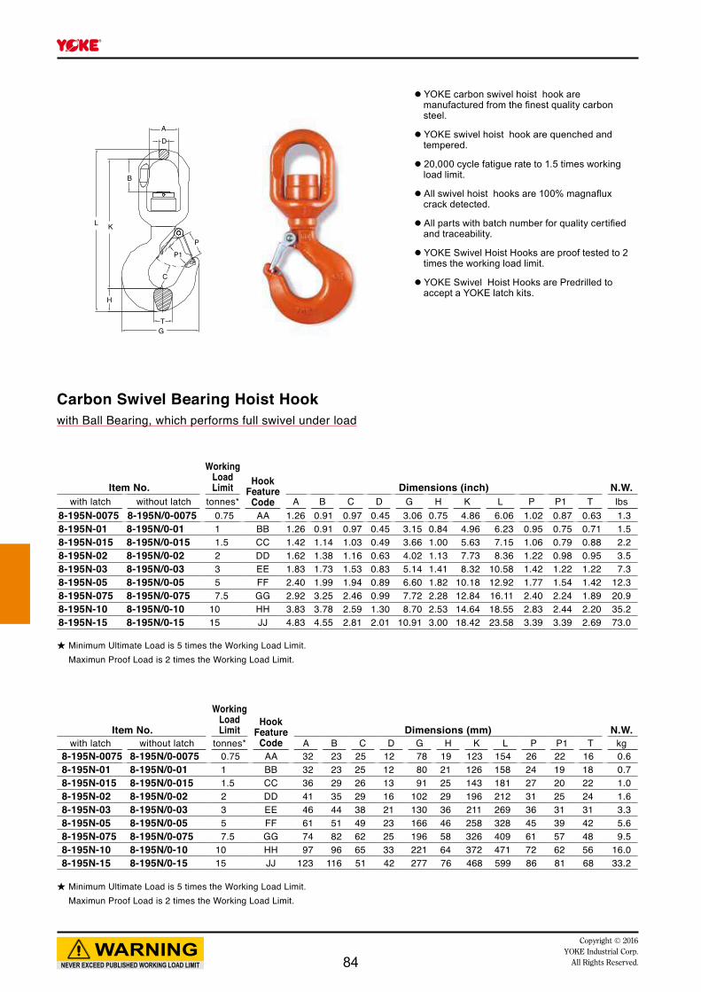
B
AD
C
PP1
K
H
GT
L
NEVER EXCEED PUBLISHED WORKING LOAD LIMIT
WARNINGCopyright © 2016
YOKE Industrial Corp.All Rights Reserved.
● YOKE carbon swivel hoist hook are manufactured from the finest quality carbon steel.
● YOKE swivel hoist hook are quenched and tempered.
● 20,000 cycle fatigue rate to 1.5 times working load limit.
● All swivel hoist hooks are 100% magnaflux crack detected.
● All parts with batch number for quality certified and traceability.
● YOKE Swivel Hoist Hooks are proof tested to 2 times the working load limit.
● YOKE Swivel Hoist Hooks are Predrilled to accept a YOKE latch kits.
Carbon Swivel Bearing Hoist Hookwith Ball Bearing, which performs full swivel under load
★ Minimum Ultimate Load is 5 times the Working Load Limit. Maximun Proof Load is 2 times the Working Load Limit.
★ Minimum Ultimate Load is 5 times the Working Load Limit. Maximun Proof Load is 2 times the Working Load Limit.
Item No.
WorkingLoad Limit
Hook Feature
CodeDimensions (mm) N.W.
with latch without latch tonnes* A B C D G H K L P P1 T kg8-195N-0075 8-195N/0-0075 0.75 AA 32 23 25 12 78 19 123 154 26 22 16 0.68-195N-01 8-195N/0-01 1 BB 32 23 25 12 80 21 126 158 24 19 18 0.78-195N-015 8-195N/0-015 1.5 CC 36 29 26 13 91 25 143 181 27 20 22 1.08-195N-02 8-195N/0-02 2 DD 41 35 29 16 102 29 196 212 31 25 24 1.68-195N-03 8-195N/0-03 3 EE 46 44 38 21 130 36 211 269 36 31 31 3.38-195N-05 8-195N/0-05 5 FF 61 51 49 23 166 46 258 328 45 39 42 5.68-195N-075 8-195N/0-075 7.5 GG 74 82 62 25 196 58 326 409 61 57 48 9.58-195N-10 8-195N/0-10 10 HH 97 96 65 33 221 64 372 471 72 62 56 16.08-195N-15 8-195N/0-15 15 JJ 123 116 51 42 277 76 468 599 86 81 68 33.2
Item No.
WorkingLoad Limit Hook
FeatureCode
Dimensions (inch) N.W.with latch without latch tonnes* A B C D G H K L P P1 T lbs
8-195N-0075 8-195N/0-0075 0.75 AA 1.26 0.91 0.97 0.45 3.06 0.75 4.86 6.06 1.02 0.87 0.63 1.38-195N-01 8-195N/0-01 1 BB 1.26 0.91 0.97 0.45 3.15 0.84 4.96 6.23 0.95 0.75 0.71 1.58-195N-015 8-195N/0-015 1.5 CC 1.42 1.14 1.03 0.49 3.66 1.00 5.63 7.15 1.06 0.79 0.88 2.28-195N-02 8-195N/0-02 2 DD 1.62 1.38 1.16 0.63 4.02 1.13 7.73 8.36 1.22 0.98 0.95 3.58-195N-03 8-195N/0-03 3 EE 1.83 1.73 1.53 0.83 5.14 1.41 8.32 10.58 1.42 1.22 1.22 7.38-195N-05 8-195N/0-05 5 FF 2.40 1.99 1.94 0.89 6.60 1.82 10.18 12.92 1.77 1.54 1.42 12.38-195N-075 8-195N/0-075 7.5 GG 2.92 3.25 2.46 0.99 7.72 2.28 12.84 16.11 2.40 2.24 1.89 20.98-195N-10 8-195N/0-10 10 HH 3.83 3.78 2.59 1.30 8.70 2.53 14.64 18.55 2.83 2.44 2.20 35.28-195N-15 8-195N/0-15 15 JJ 4.83 4.55 2.81 2.01 10.91 3.00 18.42 23.58 3.39 3.39 2.69 73.0
84

NEVER EXCEED PUBLISHED WORKING LOAD LIMIT
WARNINGCopyright © 2016 YOKE Industrial Corp.All Rights Reserved.
8-173
AlloyEye Hoist Hook
8-193
Carbon Eye Hoist Hook
8-175
AlloySwivel Hoist
Hookbrass washer
8-175N
AlloySwivel Hoist
Hookball bearing
8-195
CarbonSwivel Hoist
Hookbrass washer
8-195N
CarbonSwivel Hoist
Hookball bearing
8-171
AlloyShank Hoist Hook
8-191
CarbonShank Hoist Hook
Hook Feature
Working Load Limit Replacement
tonnes*Code Alloy Carbon Latch kits
AA 1 0.75 8-P801-AABB 1.5 1 8-P801-BBCC 2 1.5 8-P801-CCDD 3 2 8-P801-DDEE 5 3 8-P801-EEFF 7 5 8-P801-FFGG 11 7.5 8-P801-GGHH 15 10 8-P801-HHJJ 22 15 8-P801-JJKK 30 20 8-P801-KK
Latch kits
85

Copyright © 2016YOKE Industrial Corp.All Rights Reserved. 86

p.94
p.91
p.93
p.90
8-501 8-502 8-503
8-541 8-542 8-543
8-551 8-552 8-553
8-561 8-562 8-563
8-571 8-572 8-573
8-591 8-591G
8-512 8-514 8-515
8-521 8-522 8-531
p.105
Light Snatch Block
Forged Snatch Block
Super Snatch Block
p.100
p.103
p.109
p.95
p.92
p.101
p.104
p.114
p.98
p.110
p.113
p.97
p.99
p.102
p.108
p.105
p.112
p.96
Alloy Snatch Block
Alloy HC Snatch Block
Hay Fork Pulley
Oilfield Block
Trawl Block
Quick index of YOKE Snatch Block & Trawl Block
8-532
NEVER EXCEED PUBLISHED WORKING LOAD LIMIT
WARNINGCopyright © 2016 YOKE Industrial Corp.All Rights Reserved. 87

YSB sheaves are closed die drop forged steel. Available in size from 3” to 12” satisfying your heavy duty applications.
Groove bottom hardened to 35 Rc maximizes durability of Snatch Blocks.
Superior Design Featuresof YOKE Snatch Blocks
Quality approval by:
NEVER EXCEED PUBLISHED WORKING LOAD LIMIT
WARNINGCopyright © 2016
YOKE Industrial Corp.All Rights Reserved.88

NEVER EXCEED PUBLISHED WORKING LOAD LIMIT
WARNINGCopyright © 2016 YOKE Industrial Corp.All Rights Reserved. 89

Light Snatch Block with Shackle
Item No.Sheave
Dia. BearingType
Wire Rope Size
Working Load Limit N.W. Replacement
Sheaveinch mm t* lbs kg8-501-02 3 BB 8-10 2 4 2 8-500-028-501-04 4.5 BB 10-13 4 13 6 8-500-048-501-08 6 BB 16-19 8 29 13 8-500-088-501-0808 8 BB 16-19 8 44 20 8-500-08088-501-0810 10 BB 16-19 8 46 21 8-500-08108-501-0812-16 12 BB 16 8 49 22 8-500-0812-168-501-0812-19 12 BB 19 8 49 22 8-500-0812-198-501-0814-16 14 BB 16 8 56 25 8-500-0814-168-501-0814-19 14 BB 19 8 56 25 8-500-0814-19
*Minimum Ultimate Load is 4 times the Working Load Limit.**Available from August, 2015
Sheave by Closed Die Forged Steel
8-501-028-501-04
8-501-08 and up
********
NEVER EXCEED PUBLISHED WORKING LOAD LIMIT
WARNINGCopyright © 2016
YOKE Industrial Corp.All Rights Reserved.
● YOKE Light Snatch Blocks are manufactured of the highest quality tensile steel.
● Available from 2 tonnes to 8 tonnes, for wire rope sizes 8mm to 19mm.
● Part number, wire rope size and working load limit are marked on each block.
● Permanent batch codes link to test certificates for easy traceability.
● Supplied with bronze bushings and 4.5”-14” with pressure lube fittings.
● Meets or exceeds all requirements of ASME B30.26.
● Safety factor 4:1
● Fatigue rated
90
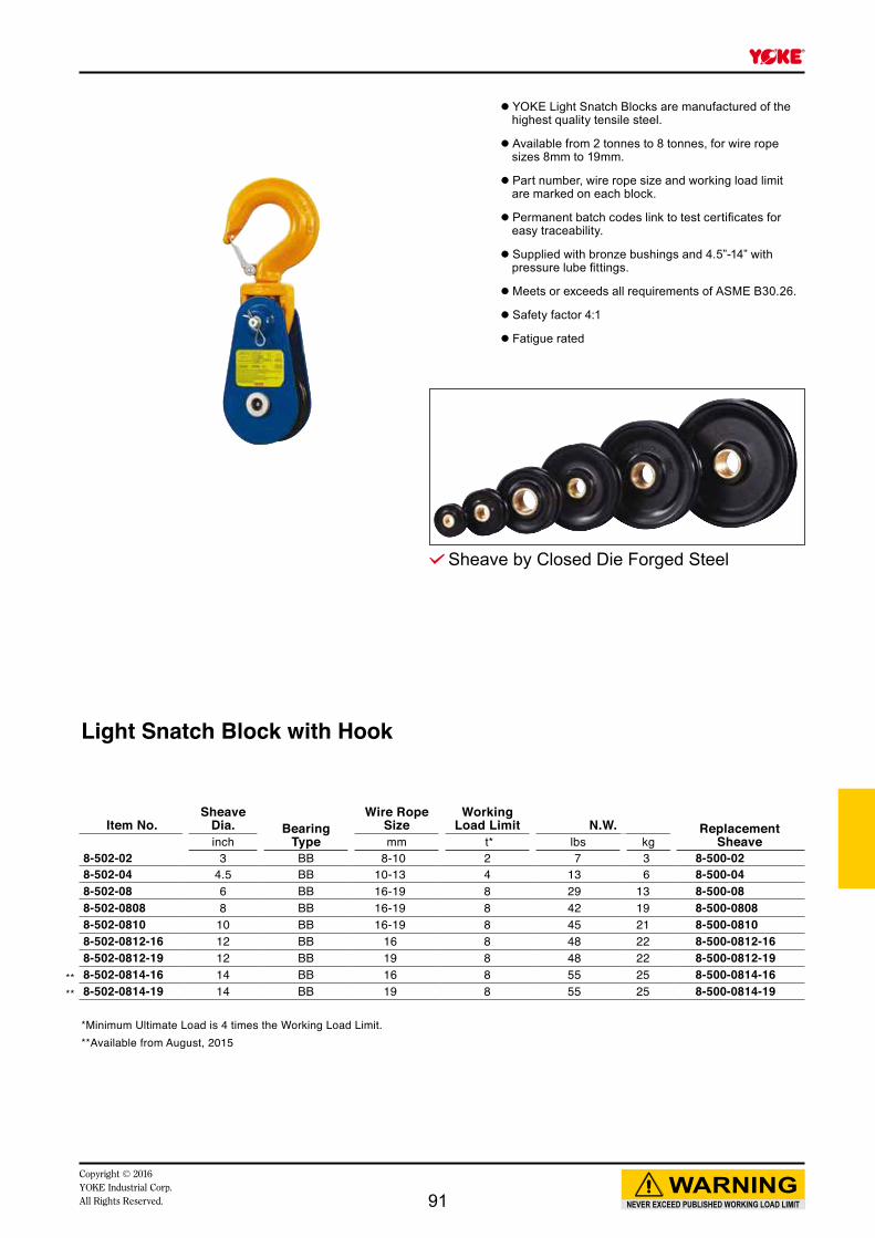
Light Snatch Block with Hook
Item No.Sheave
Dia. BearingType
Wire Rope Size
Working Load Limit N.W. Replacement
Sheaveinch mm t* lbs kg8-502-02 3 BB 8-10 2 7 3 8-500-028-502-04 4.5 BB 10-13 4 13 6 8-500-048-502-08 6 BB 16-19 8 29 13 8-500-088-502-0808 8 BB 16-19 8 42 19 8-500-08088-502-0810 10 BB 16-19 8 45 21 8-500-08108-502-0812-16 12 BB 16 8 48 22 8-500-0812-168-502-0812-19 12 BB 19 8 48 22 8-500-0812-198-502-0814-16 14 BB 16 8 55 25 8-500-0814-168-502-0814-19 14 BB 19 8 55 25 8-500-0814-19
*Minimum Ultimate Load is 4 times the Working Load Limit.**Available from August, 2015
Sheave by Closed Die Forged Steel
****
NEVER EXCEED PUBLISHED WORKING LOAD LIMIT
WARNINGCopyright © 2016 YOKE Industrial Corp.All Rights Reserved.
● YOKE Light Snatch Blocks are manufactured of the highest quality tensile steel.
● Available from 2 tonnes to 8 tonnes, for wire rope sizes 8mm to 19mm.
● Part number, wire rope size and working load limit are marked on each block.
● Permanent batch codes link to test certificates for easy traceability.
● Supplied with bronze bushings and 4.5”-14” with pressure lube fittings.
● Meets or exceeds all requirements of ASME B30.26.
● Safety factor 4:1
● Fatigue rated
91

Light Tail Board
Item No.Sheave
Dia. BearingType
Wire Rope Size
Working Load Limit N.W. Replacement
Sheaveinch mm t* lbs kg8-503-02 3 BB 8-10 2 4 2 8-500-028-503-04 4.5 BB 10-13 4 8 4 8-500-048-503-08 6 BB 16-19 8 15 7 8-500-088-503-0808 8 BB 16-19 8 28 13 8-500-08088-503-0810 10 BB 16-19 8 29 13 8-500-08108-503-0812-16 12 BB 16 8 36 16 8-500-0812-168-503-0812-19 12 BB 19 8 36 16 8-500-0812-198-503-0814-16 14 BB 16 8 43 20 8-500-0814-168-503-0814-19 14 BB 19 8 43 20 8-500-0814-19
*Minimum Ultimate Load is 4 times the Working Load Limit.**Available from August, 2015
Sheave by Closed Die Forged Steel
****
NEVER EXCEED PUBLISHED WORKING LOAD LIMIT
WARNINGCopyright © 2016
YOKE Industrial Corp.All Rights Reserved.
● YOKE Light Snatch Blocks are manufactured of the highest quality tensile steel.
● Available from 2 tonnes to 8 tonnes, for wire rope sizes 8mm to 19mm.
● Part number, wire rope size and working load limit are marked on each block.
● Permanent batch codes link to test certificates for easy traceability.
● Supplied with bronze bushings and 4.5”-14” with pressure lube fittings.
● Meets or exceeds all requirements of ASME B30.26.
● Safety factor 4:1
● Fatigue rated
92

Forged Snatch Block with Shackle
Item No.Sheave
Dia. BearingType
Wire Rope Size
Working Load Limit N.W. Replacement
Sheaveinch mm t* lbs kg8-541-12 6 BB 19-22 12 52 24 8-500-128-541-15 8 BB 19-22 15 61 28 8-500-158-541-1510 10 BB 19-22 15 90 41 8-500-1510
*Minimum Ultimate Load is 4 times the Working Load Limit.
Sheave by Closed Die Forged Steel
NEVER EXCEED PUBLISHED WORKING LOAD LIMIT
WARNINGCopyright © 2016 YOKE Industrial Corp.All Rights Reserved.
● YOKE Forged Snatch Blocks are manufactured of the highest quality forged alloy steel.
● Available from 12 tonnes to 15 tonnes, for wire rope sizes 19mm to 22mm.
● Part number, wire rope size and working load limit are marked on each block.
● Permanent batch codes link to test certificates for easy traceability.
● Supplied with bronze bushings and pressure lube fittings.
● Meets or exceeds all requirements of ASME B30.26.
● Safety factor 4:1
● Fatigue rated
93
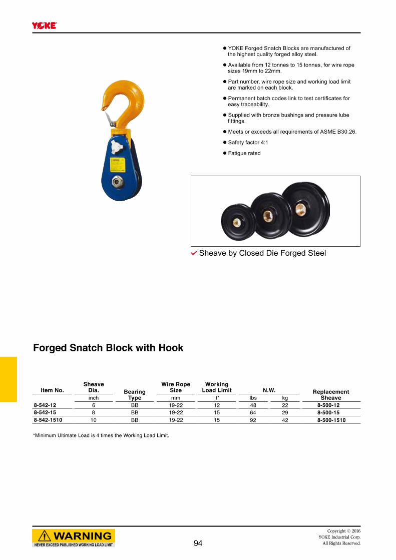
Forged Snatch Block with Hook
Item No.Sheave
Dia. BearingType
Wire Rope Size
Working Load Limit N.W. Replacement
Sheaveinch mm t* lbs kg8-542-12 6 BB 19-22 12 48 22 8-500-128-542-15 8 BB 19-22 15 64 29 8-500-158-542-1510 10 BB 19-22 15 92 42 8-500-1510
*Minimum Ultimate Load is 4 times the Working Load Limit.
Sheave by Closed Die Forged Steel
NEVER EXCEED PUBLISHED WORKING LOAD LIMIT
WARNINGCopyright © 2016
YOKE Industrial Corp.All Rights Reserved.
● YOKE Forged Snatch Blocks are manufactured of the highest quality forged alloy steel.
● Available from 12 tonnes to 15 tonnes, for wire rope sizes 19mm to 22mm.
● Part number, wire rope size and working load limit are marked on each block.
● Permanent batch codes link to test certificates for easy traceability.
● Supplied with bronze bushings and pressure lube fittings.
● Meets or exceeds all requirements of ASME B30.26.
● Safety factor 4:1
● Fatigue rated
94

Forged Tail Board
Item No.Sheave
Dia. BearingType
Wire Rope Size
Working Load Limit N.W. Replacement
Sheaveinch mm t* lbs kg8-543-12 6 BB 19-22 12 29 14 8-500-128-543-15 8 BB 19-22 15 38 17 8-500-158-543-1510 10 BB 19-22 15 67 31 8-500-1510
*Minimum Ultimate Load is 4 times the Working Load Limit.
Sheave by Closed Die Forged Steel
NEVER EXCEED PUBLISHED WORKING LOAD LIMIT
WARNINGCopyright © 2016 YOKE Industrial Corp.All Rights Reserved.
● YOKE Forged Snatch Blocks are manufactured of the highest quality forged alloy steel.
● Available from 12 tonnes to 15 tonnes, for wire rope sizes 19mm to 22mm.
● Part number, wire rope size and working load limit are marked on each block.
● Permanent batch codes link to test certificates for easy traceability.
● Supplied with bronze bushings and pressure lube fittings.
● Meets or exceeds all requirements of ASME B30.26.
● Safety factor 4:1
● Fatigue rated
95

Super Snatch Block with Shackle
Item No.Sheave
Dia. BearingType
Wire Rope Size
Working Load Limit N.W. Replacement
Sheaveinch mm t* lbs kg8-551-20 8 BB 25-29 20 92 42 8-500-208-551-2010 10 BB 25-29 20 119 54 8-500-20108-551-2012-25 12 BB 25 20 139 63 8-500-2012-258-551-2012-29 12 BB 29 20 139 63 8-500-2012-298-551-2015-25 14 BB 25 20 150 68 8-500-2015-258-551-2015-29 14 BB 29 20 150 68 8-500-2015-298-551-2518-25 18 BB 25 25 260 118 8-500-2518-258-551-2518-29 18 BB 29 25 260 118 8-500-2518-298-551-3020-29 20 BB 29 30 398 181 8-500-3020-298-551-3020-32 20 BB 32 30 400 182 8-500-3020-328-551-3024-29 24 BB 29 30 475 216 8-500-3024-298-551-3024-32 24 BB 32 30 475 216 8-500-3024-32
* Minimum Ultimate Load is 4 times the Working Load Limit.** Available from August, 2015
Sheave by Closed Die Forged Steel
**************
NEVER EXCEED PUBLISHED WORKING LOAD LIMIT
WARNINGCopyright © 2016
YOKE Industrial Corp.All Rights Reserved.
● YOKE Super Snatch Blocks are manufactured of the highest quality tensile steel.
● Available from 20 tonnes to 30 tonnes, for wire rope sizes 25mm to 32mm.
● Part number, wire rope size and working load limit are marked on each block.
● Permanent batch codes link to test certificates for easy traceability.
● Supplied with bronze bushings and pressure lube fittings.
● Meets or exceeds all requirements of ASME B30.26.
● Safety factor 4:1
● Fatigue rated
96
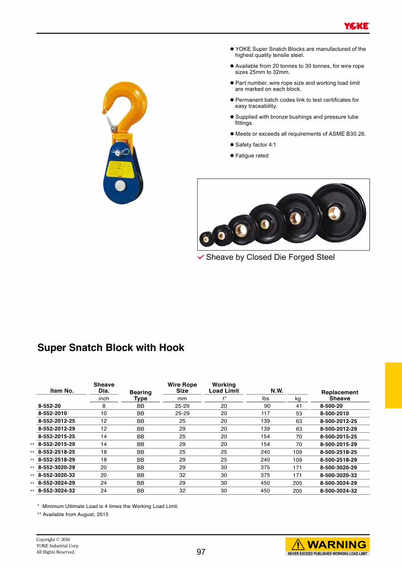
Super Snatch Block with Hook
Item No.Sheave
Dia. BearingType
Wire Rope Size
Working Load Limit N.W. Replacement
Sheaveinch mm t* lbs kg8-552-20 8 BB 25-29 20 90 41 8-500-208-552-2010 10 BB 25-29 20 117 53 8-500-20108-552-2012-25 12 BB 25 20 139 63 8-500-2012-258-552-2012-29 12 BB 29 20 139 63 8-500-2012-298-552-2015-25 14 BB 25 20 154 70 8-500-2015-258-552-2015-29 14 BB 29 20 154 70 8-500-2015-298-552-2518-25 18 BB 25 25 240 109 8-500-2518-258-552-2518-29 18 BB 29 25 240 109 8-500-2518-298-552-3020-29 20 BB 29 30 375 171 8-500-3020-298-552-3020-32 20 BB 32 30 375 171 8-500-3020-328-552-3024-29 24 BB 29 30 450 205 8-500-3024-298-552-3024-32 24 BB 32 30 450 205 8-500-3024-32
* Minimum Ultimate Load is 4 times the Working Load Limit.** Available from August, 2015
Sheave by Closed Die Forged Steel
**************
NEVER EXCEED PUBLISHED WORKING LOAD LIMIT
WARNINGCopyright © 2016 YOKE Industrial Corp.All Rights Reserved.
● YOKE Super Snatch Blocks are manufactured of the highest quality tensile steel.
● Available from 20 tonnes to 30 tonnes, for wire rope sizes 25mm to 32mm.
● Part number, wire rope size and working load limit are marked on each block.
● Permanent batch codes link to test certificates for easy traceability.
● Supplied with bronze bushings and pressure lube fittings.
● Meets or exceeds all requirements of ASME B30.26.
● Safety factor 4:1
● Fatigue rated
97

Super Tail Board
Item No.Sheave
Dia. BearingType
Wire Rope Size
Working Load Limit N.W. Replacement
Sheaveinch mm t* lbs kg8-553-20 8 BB 25-29 20 51 23 8-500-208-553-2010 10 BB 25-29 20 77 35 8-500-20108-553-2012-25 12 BB 25 20 99 45 8-500-2012-258-553-2012-29 12 BB 29 20 99 45 8-500-2012-298-553-2015-25 14 BB 25 20 112 51 8-500-2015-258-553-2015-29 14 BB 29 20 112 51 8-500-2015-298-553-2518-25 18 BB 25 25 165 75 8-500-2518-258-553-2518-29 18 BB 29 25 165 75 8-500-2518-298-553-3020-29 20 BB 29 30 215 98 8-500-3020-298-553-3020-32 20 BB 32 30 215 98 8-500-3020-328-553-3024-29 24 BB 29 30 290 132 8-500-3024-298-553-3024-32 24 BB 32 30 290 132 8-500-3024-32
* Minimum Ultimate Load is 4 times the Working Load Limit.** Available from August, 2015
Sheave by Closed Die Forged Steel
● YOKE Super Snatch Blocks are manufactured of the highest quality tensile steel.
● Available from 20 tonnes to 30 tonnes, for wire rope sizes 25mm to 32mm.
● Part number, wire rope size and working load limit are marked on each block.
● Permanent batch codes link to test certificates for easy traceability.
● Supplied with bronze bushings and pressure lube fittings.
● Meets or exceeds all requirements of ASME B30.26.
● Safety factor 4:1
● Fatigue rated
**************
NEVER EXCEED PUBLISHED WORKING LOAD LIMIT
WARNINGCopyright © 2016
YOKE Industrial Corp.All Rights Reserved.98
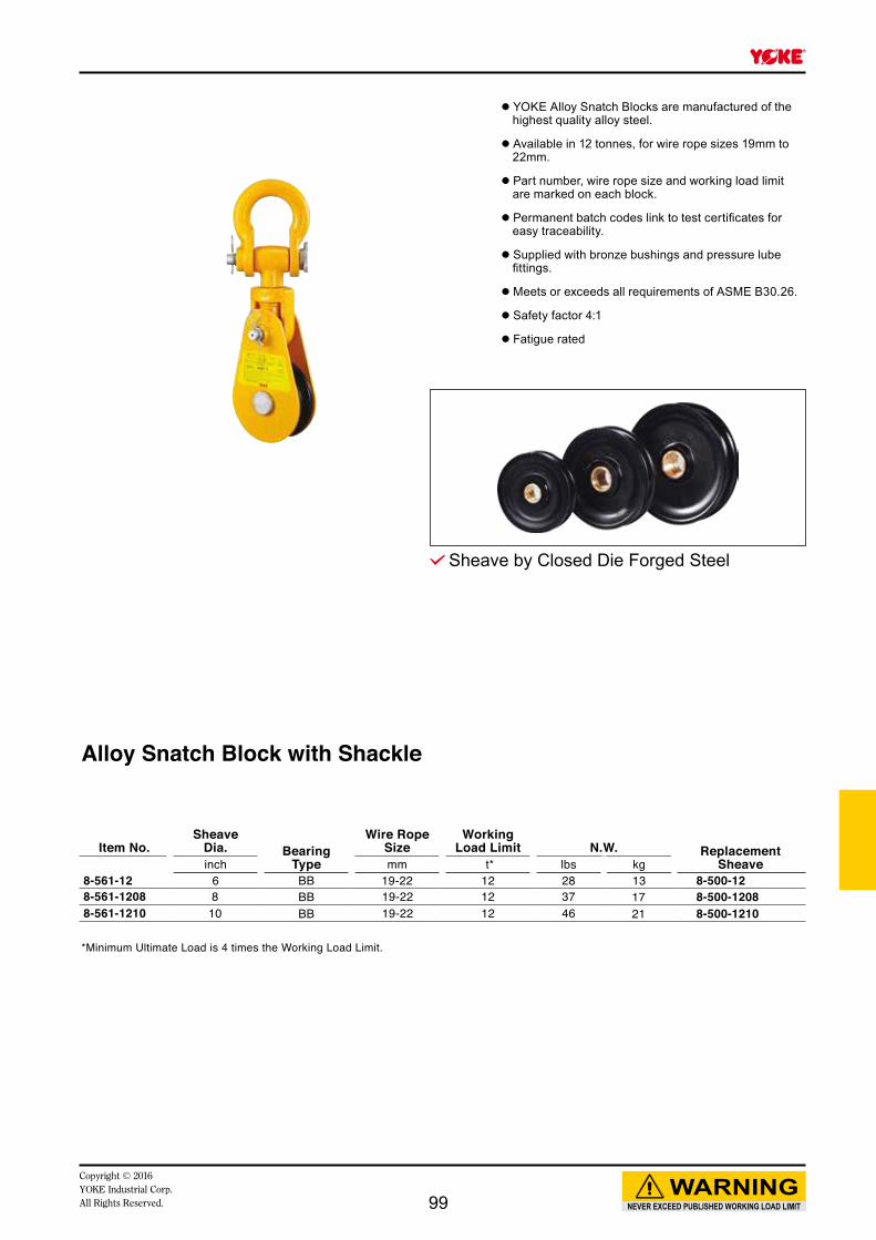
Alloy Snatch Block with Shackle
Item No.Sheave
Dia. BearingType
Wire Rope Size
Working Load Limit N.W. Replacement
Sheaveinch mm t* lbs kg8-561-12 6 BB 19-22 12 28 13 8-500-128-561-1208 8 BB 19-22 12 37 17 8-500-12088-561-1210 10 BB 19-22 12 46 21 8-500-1210
*Minimum Ultimate Load is 4 times the Working Load Limit.
Sheave by Closed Die Forged Steel
● YOKE Alloy Snatch Blocks are manufactured of the highest quality alloy steel.
● Available in 12 tonnes, for wire rope sizes 19mm to 22mm.
● Part number, wire rope size and working load limit are marked on each block.
● Permanent batch codes link to test certificates for easy traceability.
● Supplied with bronze bushings and pressure lube fittings.
● Meets or exceeds all requirements of ASME B30.26.
● Safety factor 4:1
● Fatigue rated
NEVER EXCEED PUBLISHED WORKING LOAD LIMIT
WARNINGCopyright © 2016 YOKE Industrial Corp.All Rights Reserved. 99
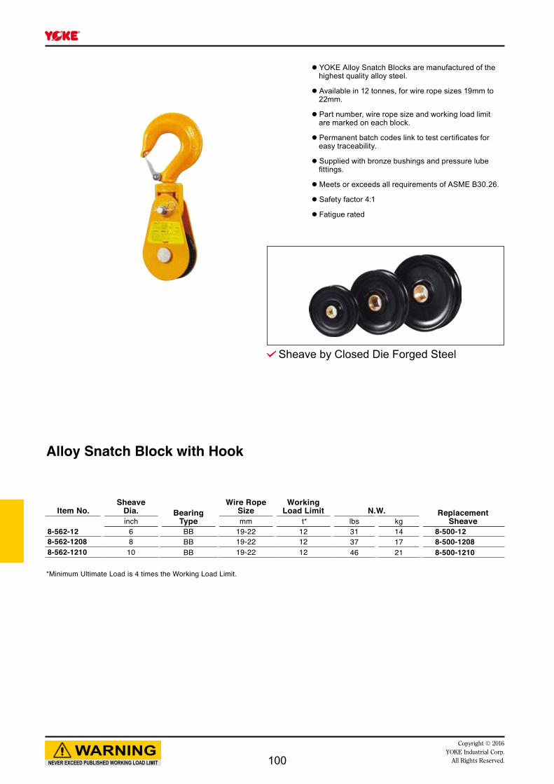
Alloy Snatch Block with Hook
Item No.Sheave
Dia. BearingType
Wire Rope Size
Working Load Limit N.W. Replacement
Sheaveinch mm t* lbs kg8-562-12 6 BB 19-22 12 31 14 8-500-128-562-1208 8 BB 19-22 12 37 17 8-500-12088-562-1210 10 BB 19-22 12 46 21 8-500-1210
*Minimum Ultimate Load is 4 times the Working Load Limit.
Sheave by Closed Die Forged Steel
● YOKE Alloy Snatch Blocks are manufactured of the highest quality alloy steel.
● Available in 12 tonnes, for wire rope sizes 19mm to 22mm.
● Part number, wire rope size and working load limit are marked on each block.
● Permanent batch codes link to test certificates for easy traceability.
● Supplied with bronze bushings and pressure lube fittings.
● Meets or exceeds all requirements of ASME B30.26.
● Safety factor 4:1
● Fatigue rated
NEVER EXCEED PUBLISHED WORKING LOAD LIMIT
WARNINGCopyright © 2016
YOKE Industrial Corp.All Rights Reserved.100
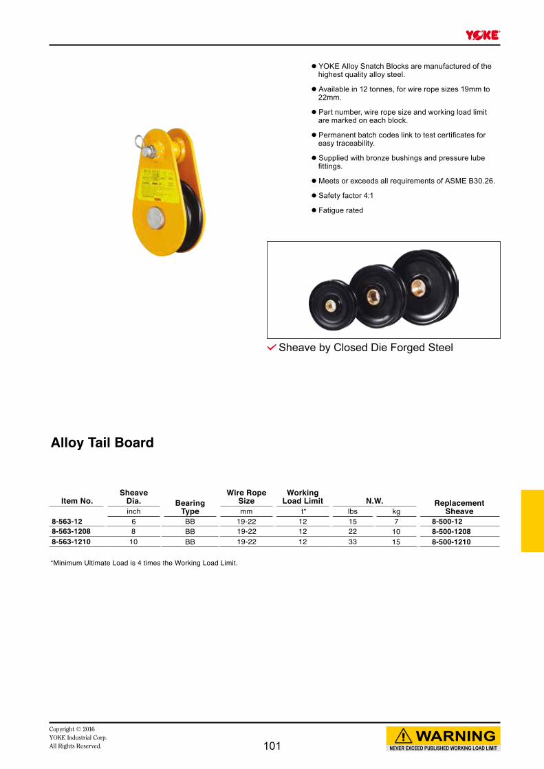
Alloy Tail Board
Item No.Sheave
Dia. BearingType
Wire Rope Size
Working Load Limit N.W. Replacement
Sheaveinch mm t* lbs kg8-563-12 6 BB 19-22 12 15 7 8-500-128-563-1208 8 BB 19-22 12 22 10 8-500-12088-563-1210 10 BB 19-22 12 33 15 8-500-1210
*Minimum Ultimate Load is 4 times the Working Load Limit.
Sheave by Closed Die Forged Steel
● YOKE Alloy Snatch Blocks are manufactured of the highest quality alloy steel.
● Available in 12 tonnes, for wire rope sizes 19mm to 22mm.
● Part number, wire rope size and working load limit are marked on each block.
● Permanent batch codes link to test certificates for easy traceability.
● Supplied with bronze bushings and pressure lube fittings.
● Meets or exceeds all requirements of ASME B30.26.
● Safety factor 4:1
● Fatigue rated
NEVER EXCEED PUBLISHED WORKING LOAD LIMIT
WARNINGCopyright © 2016 YOKE Industrial Corp.All Rights Reserved. 101

Alloy HC Snatch Block with Shackle
Item No.Sheave
Dia. BearingType
Wire Rope Size
Working Load Limit N.W. Replacement
Sheaveinch mm t* lbs kg8-571-2508-25 8 BB 25 25 90 41 8-500-2508-258-571-2508-29 8 BB 29 25 90 41 8-500-2508-298-571-2510-25 10 BB 25 25 107 49 8-500-2510-258-571-2510-29 10 BB 29 25 107 49 8-500-2510-298-571-2510-32 10 BB 32 25 107 49 8-500-2510-328-571-3012-25 12 BB 25 30 165 75 8-500-3012-258-571-3012-29 12 BB 29 30 165 75 8-500-3012-298-571-3014-25 14 BB 25 30 180 82 8-500-3014-258-571-3014-29 14 BB 29 30 180 82 8-500-3014-29
* Minimum Ultimate Load is 4 times the Working Load Limit.** Avai lable f rom August, 2015
Sheave by Closed Die Forged Steel
● YOKE Alloy HC Snatch Blocks are manufactured of the highest quality alloy steel.
● Available from 25 tonnes to 30 tonnes, for wire rope sizes 25mm to 32mm.
● Part number, wire rope size and working load limit are marked on each block.
● Permanent batch codes link to test certificates for easy traceability.
● Supplied with bronze bushings and pressure lube fittings.
● Meets or exceeds all requirements of ASME B30.26.
● Safety factor 4:1
● Fatigue rated
****
NEVER EXCEED PUBLISHED WORKING LOAD LIMIT
WARNINGCopyright © 2016
YOKE Industrial Corp.All Rights Reserved.102

Alloy HC Snatch Block with Hook
Item No.Sheave
Dia. BearingType
Wire Rope Size
Working Load Limit N.W. Replacement
Sheaveinch mm t* lbs kg8-572-2508-25 8 BB 25 25 90 41 8-500-2508-258-572-2508-29 8 BB 29 25 90 41 8-500-2508-298-572-2510-25 10 BB 25 25 107 49 8-500-2510-258-572-2510-29 10 BB 29 25 107 49 8-500-2510-298-572-2510-32 10 BB 32 25 107 49 8-500-2510-328-572-3012-25 12 BB 25 30 165 75 8-500-3012-258-572-3012-29 12 BB 29 30 165 75 8-500-3012-298-572-3014-25 14 BB 25 30 180 82 8-500-3014-258-572-3014-29 14 BB 29 30 180 82 8-500-3014-29
* Minimum Ultimate Load is 4 times the Working Load Limit.** Avai lable f rom August, 2015
Sheave by Closed Die Forged Steel
● YOKE Alloy HC Snatch Blocks are manufactured of the highest quality alloy steel.
● Available from 25 tonnes to 30 tonnes, for wire rope sizes 25mm to 32mm.
● Part number, wire rope size and working load limit are marked on each block.
● Permanent batch codes link to test certificates for easy traceability.
● Supplied with bronze bushings and pressure lube fittings.
● Meets or exceeds all requirements of ASME B30.26.
● Safety factor 4:1
● Fatigue rated
****
NEVER EXCEED PUBLISHED WORKING LOAD LIMIT
WARNINGCopyright © 2016 YOKE Industrial Corp.All Rights Reserved. 103

Sheave by Closed Die Forged Steel
Alloy HC Tail Board
Item No.Sheave
Dia. BearingType
Wire Rope Size
Working Load Limit N.W. Replacement
Sheaveinch mm t* lbs kg8-573-2508-25 8 BB 25 25 50 23 8-500-2508-258-573-2508-29 8 BB 29 25 50 23 8-500-2508-298-573-2510-25 10 BB 25 25 65 30 8-500-2510-258-573-2510-29 10 BB 29 25 65 30 8-500-2510-298-573-2510-32 10 BB 32 25 65 30 8-500-2510-328-573-3012-25 12 BB 25 30 95 43 8-500-3012-258-573-3012-29 12 BB 29 30 95 43 8-500-3012-298-573-3014-25 14 BB 25 30 110 50 8-500-3014-258-573-3014-29 14 BB 29 30 110 50 8-500-3014-29
*Minimum Ultimate Load is 4 times the Working Load Limit.**Avai lable f rom August, 2015
● YOKE Alloy HC Snatch Blocks are manufactured of the highest quality alloy steel.
● Available from 25 tonnes to 30 tonnes, for wire rope sizes 25mm to 32mm.
● Part number, wire rope size and working load limit are marked on each block.
● Permanent batch codes link to test certificates for easy traceability.
● Supplied with bronze bushings and pressure lube fittings.
● Meets or exceeds all requirements of ASME B30.26.
● Safety factor 4:1
● Fatigue rated
****
NEVER EXCEED PUBLISHED WORKING LOAD LIMIT
WARNINGCopyright © 2016
YOKE Industrial Corp.All Rights Reserved.104

Galvanized
Oilfield Hoist Block
Item No. Item No.Sheave
Dia. BearingType
Wire Rope Size
Working Load Limit N.W.
inch mm t* lbs kg8-591-0408 8-591-0408G 8 TB 10-13 4 35 168-591-0810-13 8-591-0810-13G 10 TB 10-13 8 55 258-591-0810-15 8-591-0810-15G 10 TB 13-15 8 55 258-591-1210-15 8-591-1210-15G 10 TB 13-15 12 55 258-591-1214-16 8-591-1214-16G 14 TB 16 12 95 438-591-1214-19 8-591-1214-19G 14 TB 19 12 95 438-591-1516-22 8-591-1516-22G 16 TB 22 15 150 688-591-1516-26 8-591-1516-26G 16 TB 26 15 150 688-591-2518 8-591-2518G 18 TB 29 25 260 1188-591-3020 8-591-3020G 20 TB 32 30 675 307
*Minimum Ultimate Load is 4 times the Working Load Limit. TB=Tapered Bearing
● YOKE Oilfield Hoist Blocks are manufactured of the highest quality alloy steel.
● Available from 4 tonnes to 30 tonnes for wire rope sizes 8mm to 20mm.
● Part number, wire rope size and working load limit are marked on each block.
● Permanent batch codes link to test certificates for easy traceability.
● Supplied with sealed tapered bearings for extended product life and faster line speeds.
● Safety factor 4:1
● Manufactured by an API Q1 Certified facility.
NEVER EXCEED PUBLISHED WORKING LOAD LIMIT
WARNINGCopyright © 2016 YOKE Industrial Corp.All Rights Reserved. 105
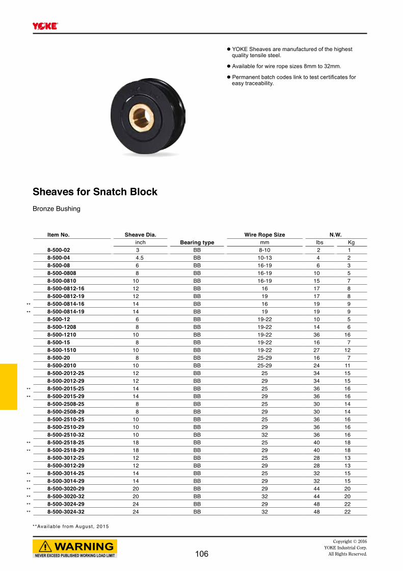
Sheaves for Snatch BlockBronze Bushing
Item No. Sheave Dia.Bearing type
Wire Rope Size N.W.inch mm lbs Kg
8-500-02 3 BB 8-10 2 18-500-04 4.5 BB 10-13 4 28-500-08 6 BB 16-19 6 38-500-0808 8 BB 16-19 10 58-500-0810 10 BB 16-19 15 78-500-0812-16 12 BB 16 17 88-500-0812-19 12 BB 19 17 88-500-0814-16 14 BB 16 19 98-500-0814-19 14 BB 19 19 98-500-12 6 BB 19-22 10 58-500-1208 8 BB 19-22 14 68-500-1210 10 BB 19-22 36 168-500-15 8 BB 19-22 16 78-500-1510 10 BB 19-22 27 128-500-20 8 BB 25-29 16 78-500-2010 10 BB 25-29 24 118-500-2012-25 12 BB 25 34 158-500-2012-29 12 BB 29 34 158-500-2015-25 14 BB 25 36 168-500-2015-29 14 BB 29 36 168-500-2508-25 8 BB 25 30 148-500-2508-29 8 BB 29 30 148-500-2510-25 10 BB 25 36 168-500-2510-29 10 BB 29 36 168-500-2510-32 10 BB 32 36 168-500-2518-25 18 BB 25 40 188-500-2518-29 18 BB 29 40 188-500-3012-25 12 BB 25 28 138-500-3012-29 12 BB 29 28 138-500-3014-25 14 BB 25 32 158-500-3014-29 14 BB 29 32 158-500-3020-29 20 BB 29 44 208-500-3020-32 20 BB 32 44 208-500-3024-29 24 BB 29 48 228-500-3024-32 24 BB 32 48 22
**Avai lable f rom August, 2015
● YOKE Sheaves are manufactured of the highest quality tensile steel.
● Available for wire rope sizes 8mm to 32mm.
● Permanent batch codes link to test certificates for easy traceability.
****
****
****
************
NEVER EXCEED PUBLISHED WORKING LOAD LIMIT
WARNINGCopyright © 2016
YOKE Industrial Corp.All Rights Reserved.106

Snatch Block with Swivel Eye
Item No.Sheave
Dia. BearingType
Wire Rope Size
Working Load Limit N.W. Replacement
Sheaveinch mm t* lbs kg8-504-02 3 BB 8-10 2 5 2 8-500-02
*Minimum Ultimate Load is 4 times the Working Load Limit.
Sheave by Closed Die Forged Steel
● YOKE Snatch Blocks are manufactured of the highest quality tensile steel.
● Part number, wire rope size and working load limit are marked on each block.
● Permanent batch codes link to test certificates for easy traceability.
● Supplied with bronze bushings and pressure lube fittings.
● Meets or exceeds all requirements of ASME B30.26.
● Safety factor 4:1
● Fatigue rated
NEVER EXCEED PUBLISHED WORKING LOAD LIMIT
WARNINGCopyright © 2016 YOKE Industrial Corp.All Rights Reserved. 107

Hay Fork Pulley with Swivel Hook
★ Minimum Ultimate Load is 4 times the Working Load Limit.
Item No.Working
Load LimitSheave
Dia.RopeCode
RopeSize N.W.
t* inch mm lbs kg8-512-01MR 1 4.5 Manila Rope 32 9 48-512-01WL 1 4.5 Wire Line 10 - 13 9 48-512-02MR 2 6 Manila Rope 38 15 78-512-02WL 2 6 Wire Line 16 15 7
● YOKE Hay Fork Pulley features one piece pressed steel shell and forged hook.
● Rounded edges to prevent rope damages.
● Supplied with bronze bushings and pressure lube fittings.
● Manila rope and wire line applications
NEVER EXCEED PUBLISHED WORKING LOAD LIMIT
WARNINGCopyright © 2016
YOKE Industrial Corp.All Rights Reserved.108
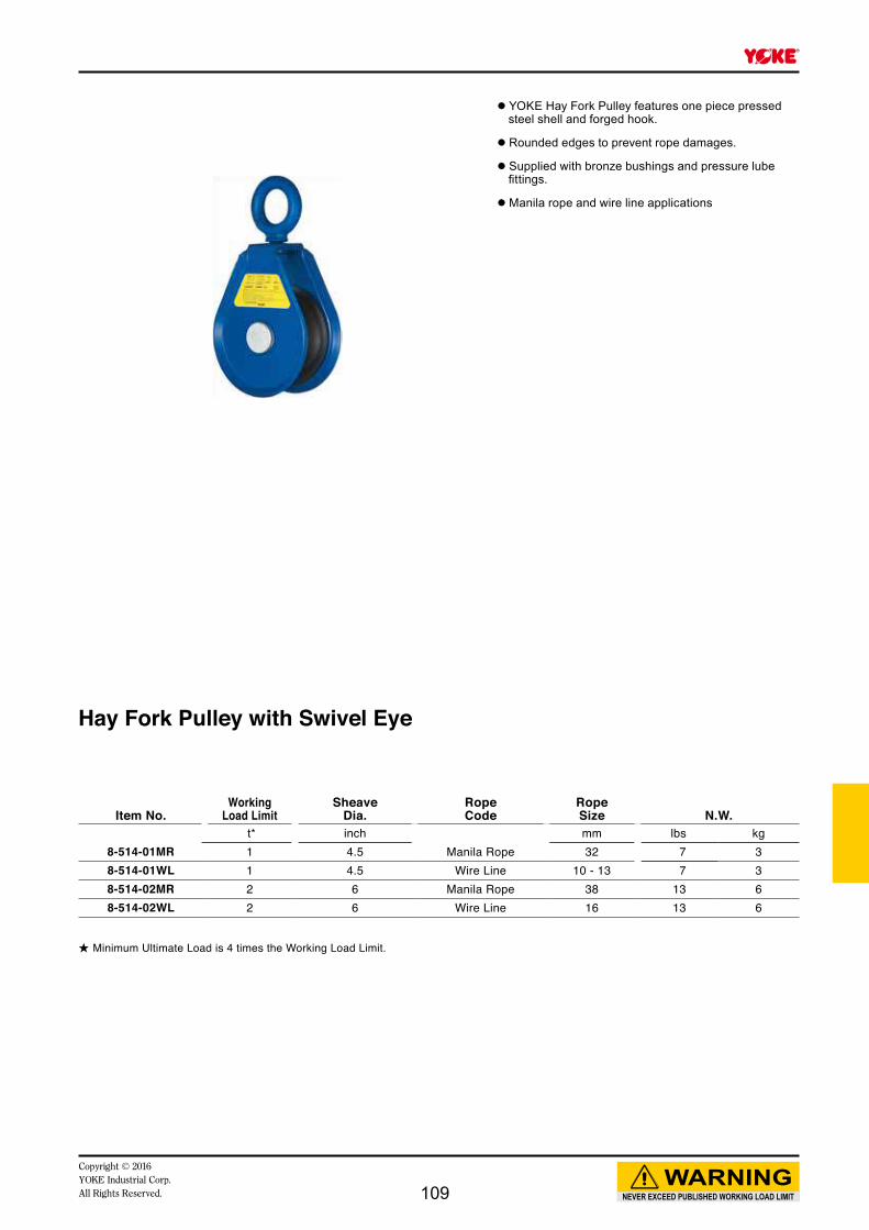
Item No.Working
Load LimitSheave
Dia.RopeCode
RopeSize N.W.
t* inch mm lbs kg8-514-01MR 1 4.5 Manila Rope 32 7 38-514-01WL 1 4.5 Wire Line 10 - 13 7 38-514-02MR 2 6 Manila Rope 38 13 68-514-02WL 2 6 Wire Line 16 13 6
Hay Fork Pulley with Swivel Eye
★ Minimum Ultimate Load is 4 times the Working Load Limit.
● YOKE Hay Fork Pulley features one piece pressed steel shell and forged hook.
● Rounded edges to prevent rope damages.
● Supplied with bronze bushings and pressure lube fittings.
● Manila rope and wire line applications
NEVER EXCEED PUBLISHED WORKING LOAD LIMIT
WARNINGCopyright © 2016 YOKE Industrial Corp.All Rights Reserved. 109

Item No.Working
Load LimitSheave
Dia.RopeCode
RopeSize N.W.
t* inch Wire Line
mm lbs kg8-515-02WL 2 8 13 13 6
Hay Fork Pulley with Swivel Eye
★ Minimum Ultimate Load is 4 times the Working Load Limit.
● YOKE Hay Fork Pulley features one piece pressed steel shell and forged hook.
● Rounded edges to prevent rope damages.
● Supplied with bronze bushings and pressure lube fittings.
● Manila rope and wire line applications
NEVER EXCEED PUBLISHED WORKING LOAD LIMIT
WARNINGCopyright © 2016
YOKE Industrial Corp.All Rights Reserved.110

Copyright © 2016YOKE Industrial Corp.All Rights Reserved. 111

Item No.Sheave
Dimensions (inch) Bearing TypeWorking
Load Limit N.W.inch Rim Thickness
Needle bearing t* lbs kg
8-521-05 6 2 3/4 5 27 12
Item No.Sheave
Dimensions (inch) Bearing TypeWorking
Load Limit N.W.inch Rim Thickness
Tapered bearing t* lbs kg
8-523-10 8 2 7/8 10 44 20
Trawl Blockwith Swivel Eye
Trawl Blockwith Swivel Eye
★ Minimum Ultimate Load is 4 times the Working Load Limit.
★ Minimum Ultimate Load is 4 times the Working Load Limit.
● All parts are forged: swivel eye, side plates and sheave.
● Hot dipped galvanized finish provides corrosive resistance in salt water environment.
● Supplied with needle bearings and pressure lube fittings.
● Individually tested for maximum safety.
● All parts are forged: swivel eye, side plates and sheave.
● Hot dipped galvanized finish provides corrosive resistance in salt water environment.
● Supplied with tapered bearings and pressure lube fittings.
● Individually tested for maximum safety.
NEVER EXCEED PUBLISHED WORKING LOAD LIMIT
WARNINGCopyright © 2016
YOKE Industrial Corp.All Rights Reserved.112

Item No.Sheave
Dimensions (inch) Bearing TypeWorking
Load Limit N.W.inch Rim Thickness
Bronze bushed t* lbs kg
8-522-05 6 2 3/4 5 32 15
Trawl Blockwith Swivel Eye
★ Minimum Ultimate Load is 4 times the Working Load Limit.
● Forged swivel eye and sheave, pressed side plates with extra throat opening allowing nets and fittings to pass through.
● Hot dipped galvanized finish provides corrosive resistance in salt water environment.
● Supplied with bronze bushing and pressure lube fittings.
● Individually tested for maximum safety.
NEVER EXCEED PUBLISHED WORKING LOAD LIMIT
WARNINGCopyright © 2016 YOKE Industrial Corp.All Rights Reserved. 113
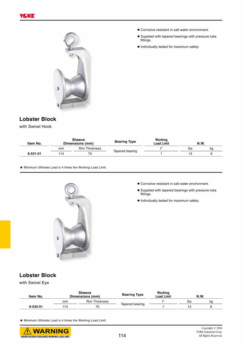
Lobster Blockwith Swivel Hook
Lobster Blockwith Swivel Eye
★ Minimum Ultimate Load is 4 times the Working Load Limit.
★ Minimum Ultimate Load is 4 times the Working Load Limit.
Item No.Sheave
Dimensions (mm) Bearing Type WorkingLoad Limit N.W.
mm Rim ThicknessTapered bearing
t* lbs kg8-531-01 114 70 1 13 6
Item No.Sheave
Dimensions (mm) Bearing Type WorkingLoad Limit N.W.
mm Rim ThicknessTapered bearing
t* lbs kg8-532-01 114 70 1 13 6
● Corrosive resistant in salt water environment.
● Supplied with tapered bearings with pressure lube fittings.
● Individually tested for maximum safety.
● Corrosive resistant in salt water environment.
● Supplied with tapered bearings with pressure lube fittings.
● Individually tested for maximum safety.
NEVER EXCEED PUBLISHED WORKING LOAD LIMIT
WARNINGCopyright © 2016
YOKE Industrial Corp.All Rights Reserved.114

100
Copyright © 2016YOKE Industrial Corp.All Rights Reserved. 115
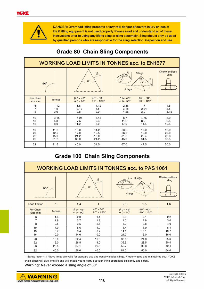
678
20222632
1.41.92.5
16.019.026.540.0
2.02.73.5
22.426.537.156.0
1.41.92.5
16.019.026.540.0
2.94.05.3
33.639.955.784.0
2.12.93.8
24.028.539.860.0
2.23.04.0
101316
4.06.7
10.0
5.69.4
14.0
4.06.7
10.0
8.414.121.0
6.010.115.0
6.410.716.025.630.442.464.0
1 1.4 1 2.1 1.5 1.6
NEVER EXCEED PUBLISHED WORKING LOAD LIMIT
WARNINGCopyright © 2016
YOKE Industrial Corp.All Rights Reserved.
DANGER:■Overhead■lifting■presents■a■very■real■danger■of■severe■injury■or■loss■of■
life■if■lifting■equipment■is■not■used■properly.Please■read■and■understand■all■of■these■
instructions■prior■to■using■any■lifting■sling■or■sling■assembly.■Sling■should■only■be■used■
by■qualified■persons■who■are■responsible■for■the■sling■selection,■inspection■and■use.■
WORKING■LOAD■LIMITS■IN■TONNES■acc.■to■EN1677■
Grade 80 Chain Sling Components
Grade 100 Chain Sling Components
WORKING■LOAD■LIMITS■IN■TONNES■acc.■to■PAS■1061
** Safety factor 4:1 Above limits are valid for standard use and equally loaded slings. Properly used and maintained your YOKE chain slings will give long life and will enable you to carry out your lifting operations efficiently and safety.Warning:■Never■exceed■a■sling■angle■of■30°■
For chainsize mm Tonnes
Tonnes
3 legs
3 legs
4 legs
4 legs
For ChainSize mm
Load Factor
Choke endless sling
Choke endless sling
116
NEVER EXCEED PUBLISHED WORKING LOAD LIMIT
WARNINGCopyright © 2016 YOKE Industrial Corp.All Rights Reserved.
SAFE USE ● Never load in excess of the rated capacity for the application. ● Keep a record of all slings in use. ● User should remove all twists from a chain leg before lifting and, should never knot a chain. ● Always use YOKE shortening hook or clutch when chain slings should be shortened. ● Always inspect to insure that chain is free from damage or wear before use. ● Always inspect all sling components prior to each use. ● Ensure that chain is protected from any sharp corners on the load. ● Ensure that the master link articulates freely on the hook of the crane or other lifting appliance. ● Never tip load hooks. The load should always be supported correctly in the bowl of the hook. ● Always use the correct size sling for the load, allowing for the included angle and the possibility of unequal loading.
● Personnel must keep all body parts from between the sling and the load, and from between the sling and the crane/hoist hook. Persons shall never ride the chain sling/rope sling or web sling or the load during lifting or while suspended. Persons must stand clear of all loads while lifting or while suspended. During lifting, with or without the load, personnel must be alert for possible snagging of the load or the chain sling.
MAINTENANCE ● A thorough examination should be carried out by a competent person at intervals at least every year or more frequently according to statutory regulations, type of use and past records.
● Chains with bent links or with cracks or gouges in the link should be replaced , as should deformed components such as bent master links , deformed hooks and any fittings showing signs of damage.
● Chain and components wear should never exceed 10%of the original dimensions. ● Once a chain sling has been overloaded it must be taken out of service. ● Store chain slings on a properly designed rack. They should not be left lying on the floor where they may suffer mechanical or corrosion damage or may be lost.
LIMITATION ON USE ● YOKE alloy chain or chain slings should not be used in acid or caustic solutions nor in heavily acidic or caustic laden atmospheres. The high tensile strength of the heat treated alloy material in alloy steel chains and components is susceptible to hydrogen embrittlement when exposed to acids.
● YOKE slings must not be heat-treated, galvanized, plated, coated or subject to any process involving heating or picking. Each of these processes can have dangerous effects and will invalidate the manufacturer certificate.
● YOKE slings may be used at temperatures between -40°C to 200°C with no reduction in the working load limit . The use of YOKE chain slings within the permissible temperature range in the table below does not require any permanent reduction in working load limit when the chain sling is returned to normal temperatures. A sling accidentally exposed to temperatures in excess of the maximum permissible should be withdrawn form service immediately and returned to the distributor for thorough examination.
● When using YOKE slings in exceptionally hazardous conditions, the degree of hazard should be assessed by a competent person and the Working Load Limit adjusted accordingly. Examples are lifting of potentially dangerous loads such as molten metals, corrosive materials or fissile material and including certain offshore activities.
Sling■temperatureReduction■in■working■
Load■Limit■■■
-40℃ to 200℃ None
200℃ to 300℃ 10%
300℃ to 400℃ 25%
Above 400℃ Do not use.
117

NEVER EXCEED PUBLISHED WORKING LOAD LIMIT
WARNINGCopyright © 2016
YOKE Industrial Corp.All Rights Reserved.
Examples Of Chain Slings
118

NEVER EXCEED PUBLISHED WORKING LOAD LIMIT
WARNINGCopyright © 2016 YOKE Industrial Corp.All Rights Reserved.
Examples Of Wire Rope Sling & Web Sling
119
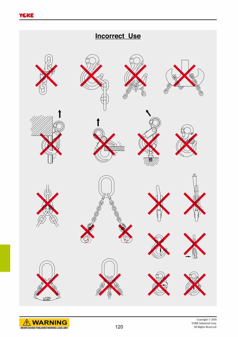
>120›
NEVER EXCEED PUBLISHED WORKING LOAD LIMIT
WARNINGCopyright © 2016
YOKE Industrial Corp.All Rights Reserved.
Incorrect Use
120

IL
D
IW
B
A
K
D
D
B
A
K
NEVER EXCEED PUBLISHED WORKING LOAD LIMIT
WARNINGCopyright © 2016YOKE Industrial Corp.All Rights Reserved.
100
special pin and sleeve designed for more often re-use purpose.
★ Design factor 4:1 proof tested and certified.
★ Design factor 4:1 proof tested and certified.
Item No.Working
Load Limit
ForGrade 100
Chain Dimensions (mm) N.W.tonnes* mm A B D K kg
X-015-06 1.4 6 15 18 7 45 0.08X-015-07 2.5 7, 8 18 25 9 59 0.2X-015-10 4.0 10 25 28 11 69 0.3X-015-13 6.7 13 30 38 16 92 0.7X-015-16 10.0 16 36 41 19 101 1.2X-015-20 16.0 20 42 50 23 122 2.1X-015-22 19.0 22 49 63 24 152 3.5X-015-26 26.5 26 55 66 30 162 4.8X-015-32 40.0 32 69 85 36 203 9.0
Item No.Working
Load Limit
ForGrade 100
Chain Dimensions (mm) N.W.tonnes* mm A B D K kg
X-M015-06 1.4 6 15 18 7 45 0.08X-M015-07 2.5 7, 8 18 25 9 59 0.2X-M015-10 4.0 10 25 28 11 69 0.3X-M015-13 6.7 13 30 38 16 92 0.7X-M015-16 10.0 16 36 41 19 101 1.2X-M015-20 16.0 20 42 50 23 122 2.1X-M015-22 19.0 22 49 63 24 152 3.5X-M015-26 26.5 26 55 66 30 162 4.9X-M015-32 40.0 32 69 85 36 203 9.3
Item No.WLL
β0-45°
ForGrade 100
Chain (mm)Dimensions
(mm) N.W.tonnes* 1 Leg 2 Leg D IL IW kg
X-003-06 ※ 1.4 6 -- 11 100 60 0.2X-003-0806 ※ 2.9 7, 8 6 14 120 70 0.5X-003-1008 ※ 5.3 10 7, 8 17 140 80 0.7X-003-13 ※ 6.7 13 -- 19 150 90 1.1X-003-1310 ※ 8.4 13 10 22 160 95 1.5X-003-16 ※ 10.0 16 -- 25 190 110 2.3X-003-1613 ※ 14.1 16 13 28 180 105 2.7X-003-19 ※ 16.0 19, 20 -- 30 200 120 3.5X-003-2216 ※ 21.0 22 16 34 240 140 5.3X-003-26 ※ 26.5 26 -- 38 250 150 7.4X-003-2619 ※ 33.6 26 19, 20 40 250 150 8.2X-003-3222 ※ 39.9 32 22 45 300 180 12.3
G-100 Oblong Master Link
G-100 Connecting Link
Connecting LinkDacromet® surface finish**
★ Forged Oblong Master Links. Design factor 4:1 proof tested and certified.
121
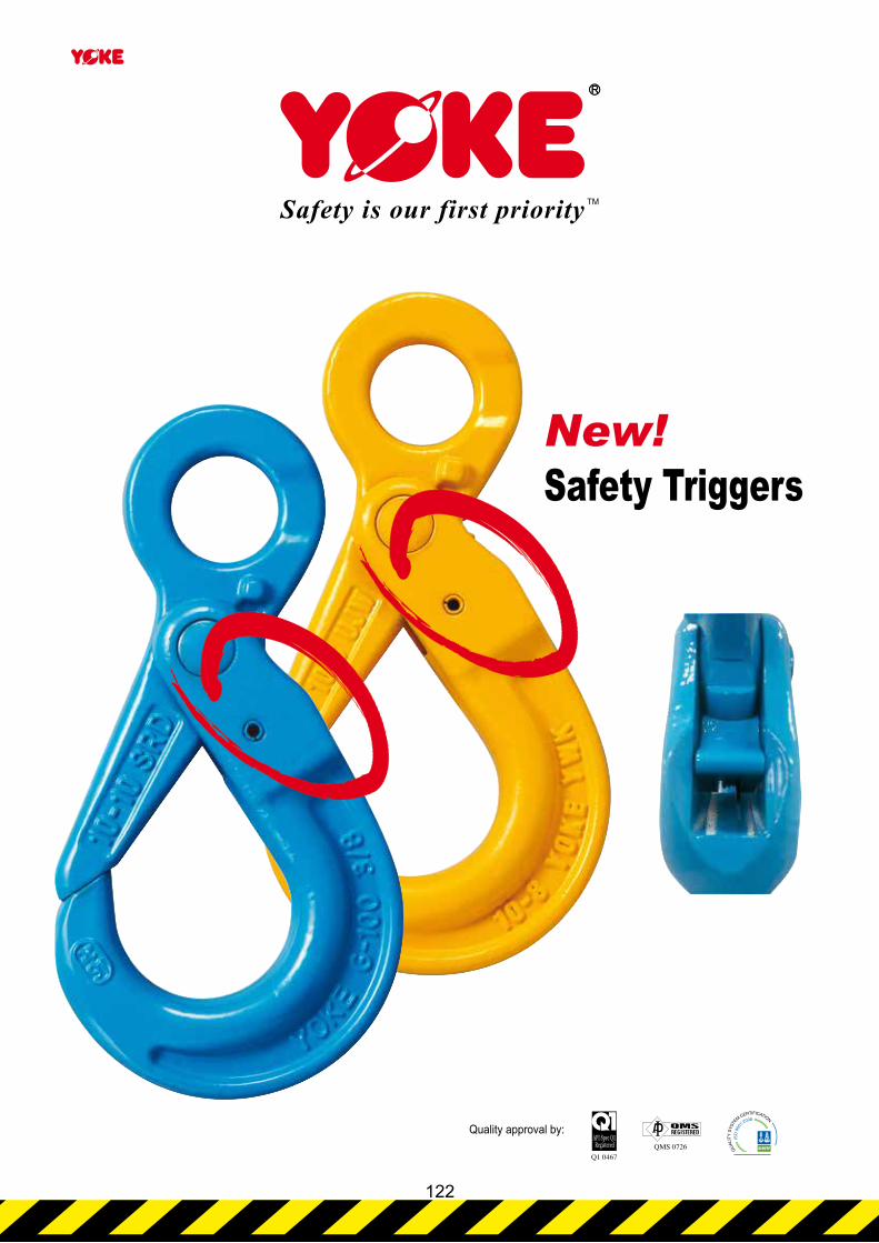
Quality approval by:
New!Safety Triggers
122

D
K
H
T
P
A
P
K
H
T
A
PP
NEVER EXCEED PUBLISHED WORKING LOAD LIMIT
WARNINGCopyright © 2016YOKE Industrial Corp.All Rights Reserved.
100
★ Design factor 4:1 proof tested and certified.
★ Design factor 4:1 proof tested and certified.
★ Design factor 4:1 proof tested and certified.
Item No.Working
Load Limit
ForGrade 100
Chain N.W.tonnes* mm A B D H K P T kg
X-027-06 1.4 6 32 22 12 19 149 28 15 0.7X-027-07 2.5 7, 8 36 29 13 24 186 34 20 1.2X-027-10 4.0 10 41 34 16 30 218 44 26 2.0X-027-13 6.7 13 46 43 21 39 276 51 30 4.1X-027-16 10.0 16 61 50 23 49 329 60 36 7.2X-027-20 16.0 20 74 82 25 65 387 70 53 13.0X-027-22 19.0 22 97 95 33 63 457 80 49 20.0X-027-26 26.5 26 123 115 42 69 535 99 56 33.0
Item No.Working
Load Limit
ForGrade 100
Chain Dimensions (mm) N.W.tonnes* mm A H K P T kg
X-026-06 1.4 6 6 19 93 28 15 0.4X-026-07 2.5 7, 8 9 24 119 34 20 0.9X-026-10 4.0 10 11 30 142 44 26 1.4X-026-13 6.7 13 14 39 178 51 30 3.0X-026-16 10.0 16 18 49 213 60 36 5.0X-026-20 16.0 20 21 65 244 70 53 11.0X-026-22 19.0 22 24 63 273 80 49 13.5
G-100 Eye Self Locking Hook
G-100 Clevis Self Locking Hook
G-100 Swivel Self Locking HookWith Brass Bushing
Item No.Working
Load Limit
ForGrade 100
Chain Dimensions (mm) N.W.tonnes* mm A D H K P T kg
X-025-06 1.4 6 21 10 19 110 28 15 0.5X-025-07 2.5 7, 8 25 11 24 136 34 20 0.8X-025-10 4.0 10 32 13 30 167 44 26 1.5X-025-13 6.7 13 40 16 39 207 51 30 3.0X-025-16 10.0 16 50 21 49 252 60 36 5.8X-025-20 16.0 20 60 23 65 290 70 53 10.0X-025-22 19.0 22 70 24 63 319 80 49 12.5X-025-26 26.5 26 80 25 69 343 99 56 15.0
WARNING INFORMATION:This hook is a positioning device and is not intended to rotate under load. For swivel hooks designed to rotate under load, see p.116 X-027N.
123
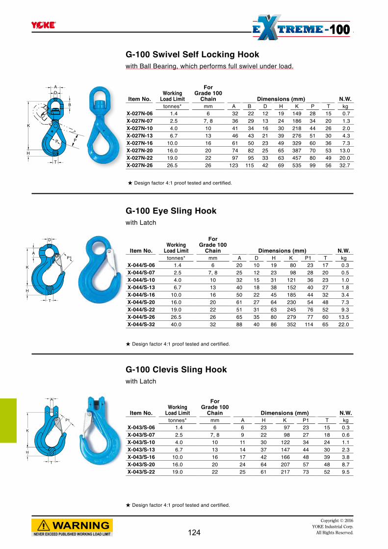
D
A
K
H
T
P1
P1
T
H
K
A
NEVER EXCEED PUBLISHED WORKING LOAD LIMIT
WARNINGCopyright © 2016
YOKE Industrial Corp.All Rights Reserved.
100
★ Design factor 4:1 proof tested and certified.
★ Design factor 4:1 proof tested and certified.
★ Design factor 4:1 proof tested and certified.
Item No.Working
Load Limit
ForGrade 100
Chain Dimensions (mm) N.W.tonnes* mm A B D H K P T kg
X-027N-06 1.4 6 32 22 12 19 149 28 15 0.7X-027N-07 2.5 7, 8 36 29 13 24 186 34 20 1.3X-027N-10 4.0 10 41 34 16 30 218 44 26 2.0X-027N-13 6.7 13 46 43 21 39 276 51 30 4.3X-027N-16 10.0 16 61 50 23 49 329 60 36 7.3X-027N-20 16.0 20 74 82 25 65 387 70 53 13.0X-027N-22 19.0 22 97 95 33 63 457 80 49 20.0X-027N-26 26.5 26 123 115 42 69 535 99 56 32.7
Item No.Working
Load Limit
ForGrade 100
Chain Dimensions (mm) N.W.tonnes* mm A D H K P1 T kg
X-044/S-06 1.4 6 20 10 19 80 23 17 0.3X-044/S-07 2.5 7, 8 25 12 23 98 28 20 0.5X-044/S-10 4.0 10 32 15 31 121 36 23 1.0X-044/S-13 6.7 13 40 18 38 152 40 27 1.8X-044/S-16 10.0 16 50 22 45 185 44 32 3.4X-044/S-20 16.0 20 61 27 64 230 54 48 7.3X-044/S-22 19.0 22 51 31 63 245 76 52 9.3X-044/S-26 26.5 26 65 35 80 279 77 60 13.5X-044/S-32 40.0 32 88 40 86 352 114 65 22.0
Item No.Working
Load Limit
ForGrade 100
Chain Dimensions (mm) N.W.tonnes* mm A H K P1 T kg
X-043/S-06 1.4 6 6 23 97 23 15 0.3X-043/S-07 2.5 7, 8 9 22 98 27 18 0.6X-043/S-10 4.0 10 11 30 122 34 24 1.1X-043/S-13 6.7 13 14 37 147 44 30 2.3X-043/S-16 10.0 16 17 42 166 48 39 3.8X-043/S-20 16.0 20 24 64 207 57 48 8.7X-043/S-22 19.0 22 25 61 217 73 52 9.5
G-100 Swivel Self Locking Hookwith Ball Bearing, which performs full swivel under load.
G-100 Eye Sling Hookwith Latch
G-100 Clevis Sling Hookwith Latch
124
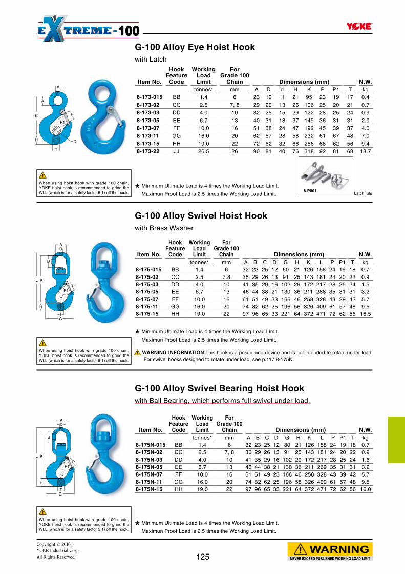
8-P801
A
d
D
P
P1K
H
T
B
AD
C
PP1
K
H
GT
L
B
AD
C
PP1
K
H
GT
L
NEVER EXCEED PUBLISHED WORKING LOAD LIMIT
WARNINGCopyright © 2016YOKE Industrial Corp.All Rights Reserved.
100
★ Minimum Ultimate Load is 4 times the Working Load Limit. Maximun Proof Load is 2.5 times the Working Load Limit.
G-100 Alloy Eye Hoist Hookwith Latch
Item No.
HookFeature
Code
WorkingLoad Limit
ForGrade 100
Chain Dimensions (mm) N.W.tonnes* mm A D d H K P P1 T kg
8-173-015 BB 1.4 6 23 19 11 21 95 23 19 17 0.48-173-02 CC 2.5 7, 8 29 20 13 26 106 25 20 21 0.78-173-03 DD 4.0 10 32 25 15 29 122 28 25 24 0.98-173-05 EE 6.7 13 40 31 18 37 149 36 31 31 2.08-173-07 FF 10.0 16 51 38 24 47 192 45 39 37 4.08-173-11 GG 16.0 20 62 57 28 58 232 61 67 48 7.08-173-15 HH 19.0 22 72 62 32 66 256 68 62 56 9.4 8-173-22 JJ 26.5 26 90 81 40 76 318 92 81 68 18.7
★ Minimum Ultimate Load is 4 times the Working Load Limit. Maximun Proof Load is 2.5 times the Working Load Limit.
G-100 Alloy Swivel Hoist Hookwith Brass Washer
Item No.
HookFeature
Code
WorkingLoad Limit
ForGrade 100
Chain Dimensions (mm) N.W.tonnes* mm A B C D G H K L P P1 T kg
8-175-015 BB 1.4 6 32 23 25 12 60 21 126 158 24 19 18 0.78-175-02 CC 2.5 7.8 35 29 26 13 91 25 143 181 24 20 22 0.98-175-03 DD 4.0 10 41 35 29 16 102 29 172 217 28 25 24 1.58-175-05 EE 6.7 13 46 44 38 21 130 36 211 288 35 31 31 3.28-175-07 FF 10.0 16 61 51 49 23 166 46 258 328 43 39 42 5.78-175-11 GG 16.0 20 74 82 62 25 196 56 326 409 61 57 48 9.58-175-15 HH 19.0 22 97 96 65 33 221 64 372 471 72 62 56 16.5
★ Minimum Ultimate Load is 4 times the Working Load Limit. Maximun Proof Load is 2.5 times the Working Load Limit.
G-100 Alloy Swivel Bearing Hoist Hookwith Ball Bearing, which performs full swivel under load.
Item No.
HookFeature
Code
WorkingLoad Limit
ForGrade 100
Chain Dimensions (mm) N.W.tonnes* mm A B C D G H K L P P1 T kg
8-175N-015 BB 1.4 6 32 23 25 12 80 21 126 158 24 19 18 0.78-175N-02 CC 2.5 7, 8 36 29 26 13 91 25 143 181 24 20 22 0.98-175N-03 DD 4.0 10 41 35 29 16 102 29 172 217 28 25 24 1.68-175N-05 EE 6.7 13 46 44 38 21 130 36 211 269 35 31 31 3.28-175N-07 FF 10.0 16 61 51 49 23 166 46 258 328 43 39 42 5.78-175N-11 GG 16.0 20 74 82 62 25 196 58 326 409 61 57 48 9.58-175N-15 HH 19.0 22 97 96 65 33 221 64 372 471 72 62 56 16.0
When using hoist hook with grade 100 chain, YOKE hoist hook is recommended to grind the WLL (which is for a safety factor 5:1) off the hook.
When using hoist hook with grade 100 chain, YOKE hoist hook is recommended to grind the WLL (which is for a safety factor 5:1) off the hook.
When using hoist hook with grade 100 chain, YOKE hoist hook is recommended to grind the WLL (which is for a safety factor 5:1) off the hook.
WARNING INFORMATION:This hook is a positioning device and is not intended to rotate under load. For swivel hooks designed to rotate under load, see p.117 8-175N.
Latch Kits
125

P
K
A
G
F
D
A
K
H
T
P
A
PK
H
T
★ Design factor 4:1 proof tested and certified.
★ Design factor 4:1 proof tested and certified.
G-100 Eye Foundry Hook
Grade 100 Clevis Foundry Hook
Item No.Working
Load Limit
ForGrade 100
Chain Dimensions (mm) N.W.tonnes* mm A D H K P T kg
X-047-07 2.5 7, 8 24 12 27 123 62 19 0.8X-047-10 4.0 10 32 15 32 149 74 23 1.6X-047-13 6.7 13 40 19 39 180 88 32 2.6X-047-16 10.0 16 50 25 47 213 98 41 4.5X-047-20 16.0 20 60 26 57 248 113 46 9.3
Item No.Working
Load Limit
ForGrade 100
Chain Dimensions (mm) N.W.tonnes* mm A F G K P kg
X-041-06 1.4 6 13 26 8 50 8 0.2X-041-07 2.5 7, 8 16 30 9 62 10 0.3X-041-10 4.0 10 20 40 13 82 13 0.6X-041-13 6.7 13 26 52 16 107 17 1.4X-041-16 10.0 16 30 57 20 132 21 2.4X-041-20 16.0 20 38 73 24 147 23 4.0X-041-22 19.0 22 38 70 26 164 26 5.0X-041-26 26.5 26 50 100 32 207 33 10.1
Item No.Working
Load Limit
ForGrade 100
Chain Dimensions (mm) N.W.tonnes* mm A H K P T kg
X-046-07 2.5 7, 8 9 27 133 62 19 0.95X-046-10 4.0 10 11 32 163 74 23 1.8X-046-13 6.7 13 14 39 200 88 32 3.6X-046-16 10.0 16 18 47 239 98 41 6.4X-046-20 16.0 20 21 62 305 113 46 11.2
NEVER EXCEED PUBLISHED WORKING LOAD LIMIT
WARNINGCopyright © 2016
YOKE Industrial Corp.All Rights Reserved.
100
★ Design factor 4:1 proof tested and certified.
G-100 Eye Grab Hook Not for use with Omega Link.No reduction of working load limit, thanks to supportingwings which prevent chain link deformation.
126

A
K
H
P
L
F
A
PL
K
BC
HT
A
P
K
H
L
F
NEVER EXCEED PUBLISHED WORKING LOAD LIMIT
WARNINGCopyright © 2016YOKE Industrial Corp.All Rights Reserved.
100
★ Design factor 4:1 proof tested and certified.
★ Design factor 4:1 proof tested and certified.
Item No.Working
Load Limit
ForGrade 100
Chain Dimensions (mm) N.W.tonnes* mm A F H K L P kg
X-042-06 1.4 6 7 25 18 47 79 8 0.2X-042-07 2.5 7, 8 10 30 22 54 93 10 0.4X-042-10 4.0 10 11 41 29 77 128 13 0.8X-042-13 6.7 13 15 52 38 99 165 17 1.6X-042-16 10.0 16 18 57 45 114 195 21 2.7X-042-20 16.0 20 22 73 52 130 222 23 4.8X-042-22 19.0 22 24 70 56 139 247 26 6.4
Item No.Working
Load Limit
ForGrade 100
Chain Dimensions (mm) N.W.tonnes* mm A F H K L P kg
X-0421-06 1.4 6 7 13 18 47 79 8 0.2X-0421-07 2.5 7, 8 10 16 22 54 93 10 0.4X-0421-10 4.0 10 12 22 29 77 128 13 0.8X-0421-13 6.7 13 15 26 38 99 165 17 1.6X-0421-16 10.0 16 18 33 45 114 195 21 2.7X-0421-20 16.0 20 22 38 52 130 222 24 4.8X-0421-22 19.0 22 25 42 56 139 247 27 6.3
Item No.Working
Load Limit
ForGrade 100
Chain Dimensions (mm) N.W.tonnes* mm A B C H K L P T kg
X-077-06 1.4 6 7 7 17 18 102 135 22 16 0.5X-077-07 2.5 7, 8 10 10 24 24 123 171 26 18 0.9X-077-10 4.0 10 12 12 28 34 149 213 34 24 1.7X-077-13 6.7 13 15 16 29 37 179 256 43 30 3.4X-077-16 10.0 16 20 19 48 42 212 305 46 39 5.7
G-100 Clevis Grab Hook
G-100 Clevis Grab Hook - Without Cradle
G-100 Clutch Sling Hook - Locking Clutch
Not for use with Omega Link.No reduction of working load limit, thanks to supportingwings which prevent chain link deformation.
Not for use with Omega Link.
★ Design factor 4:1 proof tested and certified.
Patent
127
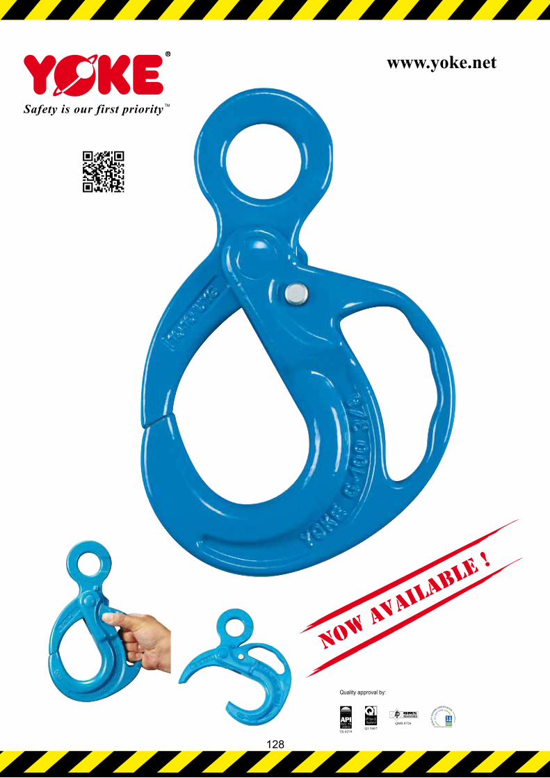
NOW AVAILABLE !
Quality approval by:
www.yoke.net
128

Patent
Patent Pending
Patent Pending
Item No.Working
Load Limit
For Grade 100
Chain Dimensions (mm) N.W.tonnes* mm A D H K O P T W kg
X-950-10 4.0 10 32 13 31 175 49 71 27 139 1.9X-950-13 6.7 13 40 16 39 227 57 80 34 174 3.0X-950-16 10.0 16 50 21 47 277 78 114 39 212 6.3X-950-20 16.0 20 60 23 56 329 91 127 54 250 11.7X-950-22 19.0 22 70 24 59 350 105 151 56 260 14.5
Item No.Working
Load Limit
For Grade 100
Chain Dimensions (mm) N.W.tonnes* (mm) A H K O P T W kg
X-951-10 4.0 10 11 31 153 49 71 27 139 1.9X-951-13 6.7 13 14 39 206 57 80 34 174 4.1X-951-16 10.0 16 18 47 243 78 114 39 212 6.4X-951-20 16.0 20 21 56 310 91 127 54 250 12.7X-951-22 19.0 22 24 59 300 105 151 56 260 14.1
Item No.Working
Load Limit
ForGrade 100
Chain Dimensions (mm) N.W.tonnes* (mm) A B D H K O P T W kg
X-952N-10 4.0 10 41 34 16 31 225 49 71 27 139 2.4X-952N-13 6.7 13 46 44 21 39 285 57 80 34 174 5.2X-952N-16 10.0 16 61 50 23 47 345 78 114 39 212 8.4X-952N-20 16.0 20 74 82 25 56 433 91 127 54 250 14.5X-952N-22 19.0 22 97 95 33 59 475 105 151 56 260 19.9
NEVER EXCEED PUBLISHED WORKING LOAD LIMIT
WARNINGCopyright © 2016YOKE Industrial Corp.All Rights Reserved.
100
★ Design factor 4:1 proof tested and certified
★ Design factor 4:1 proof tested and certified
★ Design factor 4:1 proof tested and certified
Eye Grip Safe Locking Hook
Clevis Grip Safe Locking Hook
Swivel Grip Safe Locking Hook
129

AD
K
W
B
W
K
H
T
P
NEVER EXCEED PUBLISHED WORKING LOAD LIMIT
WARNINGCopyright © 2016
YOKE Industrial Corp.All Rights Reserved.
100
★ Design factor 4:1 proof tested and certified.
★ Design factor 4:1 proof tested and certified.
★ Design factor 5:1 proof tested and certified.
G-100 Web Sling Connector
G-100 Web Sling Hook
G-100 Round Sling Self Locking Hook
Item No.Working
Load Limit
For Grade 100
Chain Dimensions (mm) N.W.tonnes* mm A B D K W kg
X-016-06 1.4 6 15 17 7 55 38 0.2X-016-07 2.5 7, 8 18 22 9 62 40 0.3X-016-10 4.0 10 25 26 11 78 47 0.6X-016-13 6.7 13 30 35 16 95 53 1.1X-016-16 10.0 16 36 38 19 115 67 2.0X-016-20 16.0 20 42 46 22 132 80 3.2X-016-22 19.0 22 49 59 24 187 125 7.7
Item No.Working
Load Limit
ForGrade 100
Chain Dimensions (mm) N.W.tonnes* mm H K P T W kg
X-028-06 1.4 6 19 138 29 15 38 0.6X-028-07 2.5 7, 8 24 169 34 20 40 1.1X-028-10 4.0 10 30 196 44 26 47 1.8X-028-13 6.7 13 39 253 52 30 53 3.9X-028-16 10.0 16 49 305 60 36 67 6.9X-028-20 16.0 20 62 328 90 48 80 12.0X-028-22 19.0 22 63 416 80 49 125 18.6
Item No.Working
Load Limit Dimensions (mm) N.W.tonnes* H K P T W kg
X-032-01 1 20 89 25 15 43 0.7X-032-02 2 27 116 30 20 53 1.5X-032-03 3 32 119 32 26 64 2.4X-032-05 5 44 145 45 38 61 3.5
130
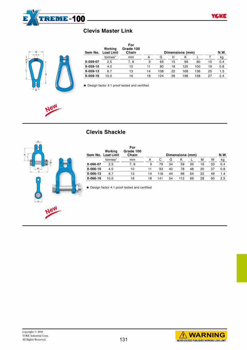
K
T
A
H
L
G Item No.Working
Load Limit
ForGrade 100
Chain Dimensions (mm) N.W.tonnes* mm A G H K L T kg
X-059-07 2.5 7, 8 9 65 15 99 80 15 0.4X-059-10 4.0 10 11 80 18 125 100 19 0.8X-059-13 6.7 13 14 108 22 168 136 25 1.5X-059-16 10.0 16 18 124 26 198 158 27 2.4
NEVER EXCEED PUBLISHED WORKING LOAD LIMIT
WARNINGCopyright © 2016YOKE Industrial Corp.All Rights Reserved.
100Clevis Master Link
★ Design factor 4:1 proof tested and certified
G
KL
W
A
C
M
Clevis Shackle
★ Design factor 4:1 proof tested and certified
Item No.Working
Load Limit
ForGrade 100
Chain Dimensions (mm) N.W.tonnes* mm A C G K L M W kg
X-066-07 2.5 7, 8 9 79 34 59 35 16 33 0.4X-066-10 4.0 10 11 93 40 78 48 20 37 0.8X-066-13 6.7 13 14 118 44 98 64 22 49 1.4X-066-16 10.0 16 18 141 54 112 69 28 60 2.5
131

Copyright © 2016YOKE Industrial Corp.All Rights Reserved. 132

IL
D
IW
D
IL
IW
NEVER EXCEED PUBLISHED WORKING LOAD LIMIT
WARNINGCopyright © 2016 YOKE Industrial Corp.All Rights Reserved.
Grade 80 Fittings
Extra width inside allows better works on large crane hooks.
Oblong Master Link, Code "MF". Connected to Chain with "YA" connecting link.
※ Forged Oblong Master Links. Design factor 4:1 proof tested and certified Tested acc. to EN 1677
※ Forged Oblong Master Links. ★ Design factor 4:1 Proof tested and certified WLL=Working Load Limit Tested acc. to EN 1677
Item No.WLL
ß 0-45°
ForGrade 80
Chain(mm) Dimensions (mm) N.W.tonnes* 1 Leg 2 Leg D IL IW kg
8-003-06 ※ 1.25 6 -- 11 100 60 0.28-003-0806 ※ 2.5 7, 8 6 14 120 70 0.48-003-1008 ※ 4.0 10 7, 8 17 140 80 0.78-003-13 ※ 5.4 13 -- 19 150 90 1.18-003-1310 ※ 7.5 13 10 22 160 95 1.58-003-16 ※ 10.0 16 -- 25 190 110 2.28-003-1613 ※ 10.0 16 13 28 180 105 2.88-003-19 ※ 12.0 19, 20 -- 30 200 120 3.88-003-2216 ※ 17.0 22 16 34 240 140 5.58-003-26 ※ 25.0 26 -- 38 250 150 7.08-003-2619 ※ 28.0 26 19, 20 40 250 150 8.08-003-3222 ※ 37.0 32 22 45 300 180 12.7
Item No.WLL
ß 0-45°
ForGrade 80
Chain(mm) Dimensions (mm) N.W.tonnes* 1 Leg 2 Leg D IL IW kg
8-003F-06 ※ 1.25 6 -- 11 100 60 0.28-003F-0806 ※ 2.5 7, 8 6 14 120 70 0.48-003F-1008 ※ 4.0 10 7, 8 17 141 80 0.78-003F-1310 ※ 7.5 13 10 23 163 95 1.58-003F-1613 ※ 10.0 16 13 29 180 105 2.88-003F-2216 ※ 17.0 20 16 34 245 140 5.38-003F-2619 ※ 25.0 -- 19, 20 40 257 150 8.0
Oblong Master Link with Flat. Code"MFF"Connected to Chain with "YO" Omega Link.
133
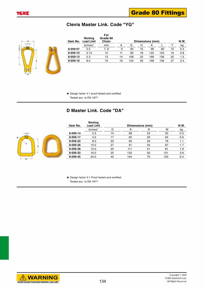
K
T
A
H
L
G
D
R
W
K
NEVER EXCEED PUBLISHED WORKING LOAD LIMIT
WARNINGCopyright © 2016
YOKE Industrial Corp.All Rights Reserved.
Grade 80 Fittings
Item No.Working
Load Limit
ForGrade 80
Chain Dimensions (mm) N.W.tonnes* mm A G H K L T kg
8-059-07 2.0 7, 8 9 65 15 99 80 15 0.48-059-10 3.15 10 11 80 18 125 100 19 0.88-059-13 5.3 13 14 108 22 168 136 25 1.58-059-16 8.0 16 18 124 26 198 158 27 2.4
Item No.Working
Load Limit Dimensions (mm) N.W.tonnes* D K R W kg
8-056-14 2.5 14 68 24 55 0.38-056-17 4.0 17 65 29 64 0.68-056-22 8.0 22 93 33 76 1.18-056-26 10.0 27 91 34 67 1.78-056-28 12.0 20 111 41 81 1.98-056-32 16.0 25 132 50 101 3.98-056-45 24.0 45 194 75 150 9.4
Clevis Master Link. Code "YG"
D Master Link. Code "DA"
★ Design factor 4:1 proof tested and certified Tested acc. to EN 1677
★ Design factor 5:1 Proof tested and certified Tested acc. to EN 1677
134

B
A
K
D
D
B
A
K
KD
P
T
8-PM015
NEVER EXCEED PUBLISHED WORKING LOAD LIMIT
WARNINGCopyright © 2016 YOKE Industrial Corp.All Rights Reserved.
Grade 80 Fittings
Connecting LinkCode " YA "
★ Design factor 4:1 proof tested and certified Tested acc. to EN 1677
Item No.Working
Load Limit
ForGrade 80
Chain Dimensions (mm) N.W.tonnes* mm A B D K kg
8-015-05 0.8 5 10 13 6 35 0.048-015-06 1.12 6 15 17 7 44 0.088-015-07 2.0 7, 8 18 22 9 57 0.28-015-10 3.15 10 25 26 11 68 0.38-015-13 5.3 13 30 35 16 91 0.78-015-16 8.0 16 36 38 19 100 1.18-015-20 12.5 18, 20 42 46 22 122 1.98-015-22 15.0 22 49 59 24 152 3.08-015-26 21.2 26 55 62 30 162 5.08-015-32 31.5 32 69 79 36 202 9.0
Connecting LinkDacromet® Surface Finish.**
★ Design factor 4:1 proof tested and certified Tested acc. to EN 1677
Item No.Working
Load Limit
ForGrade 80
Chain Dimensions (mm) N.W.tonnes* mm A B D K kg
8-M015-06 1.12 6 15 17 7 44 0.168-M015-07 2.0 7, 8 18 22 9 57 0.168-M015-10 3.15 10 25 26 11 68 0.38-M015-13 5.3 13 30 35 16 91 0.78-M015-16 8.0 16 36 38 19 100 1.28-M015-20 12.5 18, 20 42 46 22 122 1.98-M015-22 15.0 22 49 59 24 152 3.08-M015-26 21.2 26 55 62 30 162 4.68-M015-32 31.5 32 69 79 36 202 8.5
Item No.Working
Load Limit
ForGrade 80
Chain Dimensions (mm) N.W.tonnes* mm D K P T kg
8-018-06 1.12 6 21 30 8 9 0.18-018-07 2.0 7, 8 27 36 9 11 0.28-018-10 3.15 10 32 44 12 15 0.48-018-13 5.3 13 42 55 16 17 0.88-018-16 8.0 16 50 69 18 22 1.68-018-20 12.5 18, 20 58 71 21 28 2.1
Omega Link. Code"YO"
★ Design factor 4:1 proof tested and certified Tested acc. to EN 1677
special pin and sleeve designed for more often re-use purpose.
135

D
K
H
T
P
A
P
K
H
T
A
PP
NEVER EXCEED PUBLISHED WORKING LOAD LIMIT
WARNINGCopyright © 2016
YOKE Industrial Corp.All Rights Reserved.
Grade 80 FittingsHow to use YOKE Self Locking Hook?
★ Design factor 4:1 proof tested and certified Tested acc. to EN 1677
★ Design factor 4:1 proof tested and certified Tested acc. to EN 1677
Item No.Working
Load Limit
ForGrade 80
Chain Dimensions (mm) N.W.tonnes* mm A D H K P T kg
8-025-06 1.12 6 21 10 19 110 29 15 0.58-025-07 2.0 7,8 25 11 24 136 34 20 0.88-025-10 3.15 10 32 13 30 167 44 26 1.48-025-13 5.3 13 40 16 39 207 52 30 3.08-025-16 8.0 16 52 21 49 252 60 36 5.88-025-20 12.5 18, 20 64 23 62 282 90 48 8.58-025-22 15.0 22 70 24 63 319 80 49 12.58-025-26 21.2 26 80 25 69 343 99 56 14.08-025-28 25.0 28 90 28 81 401 120 63 26.0
Item No.Working
Load Limit
ForGrade 80
Chain Dimensions (mm) N.W.tonnes* mm A H K P T kg
8-026-06 1.12 6 6 19 100 29 15 0.58-026-07 2.0 7, 8 9 24 119 34 20 0.88-026-10 3.15 10 11 30 143 44 26 1.48-026-13 5.3 13 14 39 179 52 30 2.98-026-16 8.0 16 18 49 212 60 36 5.68-026-20 12.5 18, 20 21 62 243 90 48 9.08-026-22 15.0 22 24 63 273 80 49 13.0
Eye Self Locking Hook. Code "YC"
Clevis Self Locking Hook. Code"YD"
Push trigger to open Hook
136
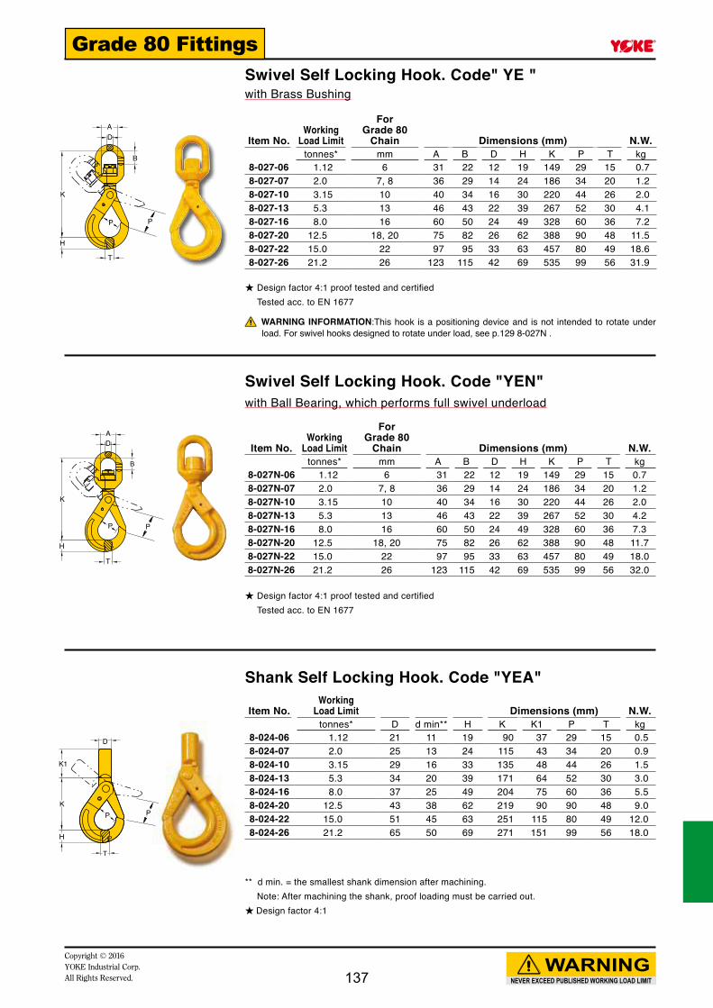
NEVER EXCEED PUBLISHED WORKING LOAD LIMIT
WARNINGCopyright © 2016 YOKE Industrial Corp.All Rights Reserved.
Grade 80 FittingsSwivel Self Locking Hook. Code" YE " with Brass Bushing
Swivel Self Locking Hook. Code "YEN"with Ball Bearing, which performs full swivel underload
Shank Self Locking Hook. Code "YEA"
★ Design factor 4:1 proof tested and certified Tested acc. to EN 1677
★ Design factor 4:1 proof tested and certified Tested acc. to EN 1677
** d min. = the smallest shank dimension after machining. Note: After machining the shank, proof loading must be carried out.★ Design factor 4:1
Item No.Working
Load Limit
ForGrade 80
Chain Dimensions (mm) N.W.tonnes* mm A B D H K P T kg
8-027-06 1.12 6 31 22 12 19 149 29 15 0.78-027-07 2.0 7, 8 36 29 14 24 186 34 20 1.28-027-10 3.15 10 40 34 16 30 220 44 26 2.08-027-13 5.3 13 46 43 22 39 267 52 30 4.18-027-16 8.0 16 60 50 24 49 328 60 36 7.28-027-20 12.5 18, 20 75 82 26 62 388 90 48 11.58-027-22 15.0 22 97 95 33 63 457 80 49 18.68-027-26 21.2 26 123 115 42 69 535 99 56 31.9
Item No.Working
Load Limit
ForGrade 80
Chain Dimensions (mm) N.W.tonnes* mm A B D H K P T kg
8-027N-06 1.12 6 31 22 12 19 149 29 15 0.78-027N-07 2.0 7, 8 36 29 14 24 186 34 20 1.28-027N-10 3.15 10 40 34 16 30 220 44 26 2.08-027N-13 5.3 13 46 43 22 39 267 52 30 4.28-027N-16 8.0 16 60 50 24 49 328 60 36 7.38-027N-20 12.5 18, 20 75 82 26 62 388 90 48 11.78-027N-22 15.0 22 97 95 33 63 457 80 49 18.08-027N-26 21.2 26 123 115 42 69 535 99 56 32.0
Item No.Working
Load Limit Dimensions (mm) N.W.tonnes* D d min** H K K1 P T kg
8-024-06 1.12 21 11 19 90 37 29 15 0.58-024-07 2.0 25 13 24 115 43 34 20 0.98-024-10 3.15 29 16 33 135 48 44 26 1.58-024-13 5.3 34 20 39 171 64 52 30 3.08-024-16 8.0 37 25 49 204 75 60 36 5.58-024-20 12.5 43 38 62 219 90 90 48 9.08-024-22 15.0 51 45 63 251 115 80 49 12.08-024-26 21.2 65 50 69 271 151 99 56 18.0
WARNING INFORMATION:This hook is a positioning device and is not intended to rotate under load. For swivel hooks designed to rotate under load, see p.129 8-027N .
137

A
K
H
T
P P
AD
B
K
H
P
T
AD
B
K
H
T
P
NEVER EXCEED PUBLISHED WORKING LOAD LIMIT
WARNINGCopyright © 2016
YOKE Industrial Corp.All Rights Reserved.
Grade 80 Fittings
★ Design factor 4:1 proof tested and certified Tested acc. to EN 1677
★ Design factor 4:1 proof tested and certified Tested acc. to EN 1677
★ Design factor 4:1 proof tested and certified Tested acc. to EN 1677
Clevis Swivel Self Locking Hook. Code " KP "with Ball Bearing, which performs full swivel under load
Eye Swivel Hook. Code " YSW "with Brass Bushing
Eye Swivel Hook. Code "YSWN " with Ball Bearing, which performs full swivel under load
Item No.Working
Load Limit
ForGrade 80
Chain Dimensions (mm) N.W.tonnes* mm A H K P T kg
8-022-06 1.12 6 6 19 156 29 15 0.88-022-07 2.0 7, 8 9 24 188 34 20 1.38-022-10 3.15 10 11 30 215 44 26 2.28-022-13 5.3 13 14 39 275 52 30 4.68-022-16 8.0 16 18 49 323 60 36 7.98-022-20 12.5 18, 20 21 62 417 90 48 13.0
Item No.Working
Load Limit
ForGrade 80
Chain Dimensions (mm) N.W.tonnes* mm A B D H K P T kg
8-049-06 1.12 6 32 23 11 19 136 24 16 0.68-049-07 2.0 7,8 36 27 12 22 155 26 18 0.98-049-10 3.15 10 41 37 16 29 189 36 23 1.68-049-13 5.3 13 46 40 21 35 233 42 28 3.28-049-16 8.0 16 60 50 22 44 280 50 35 5.38-049-20 12.5 18, 20 74 82 25 65 356 56 49 9.5
Item No.Working
Load Limit
ForGrade 80
Chain Dimensions (mm) N.W.tonnes* mm A B D H K P T kg
8-049N-06 1.12 6 32 23 11 19 136 24 16 0.68-049N-07 2.0 7, 8 36 27 12 22 155 26 18 0.98-049N-10 3.15 10 41 37 16 29 189 36 23 1.68-049N-13 5.3 13 46 40 21 35 233 42 28 3.48-049N-16 8.0 16 60 50 22 44 280 50 35 5.18-049N-20 12.5 18, 20 74 82 25 65 356 56 49 9.5
WARNING INFORMATION:This hook is a positioning device and is not intended to rotate under load. For swivel hooks designed to rotate under load, see p.130 8-049N.
138

D
A
K
H
T
P1
D
A
K
H
T
P
D
A
K
H
T
P
NEVER EXCEED PUBLISHED WORKING LOAD LIMIT
WARNINGCopyright © 2016 YOKE Industrial Corp.All Rights Reserved.
Grade 80 Fittings
to protect latch to protect latch
★ Design factor 4:1 proof tested and certified Tested acc. to EN 1677
★ Design factor 4:1 proof tested and certified Tested acc. to EN 1677
★ Design factor 4:1 proof tested and certified Tested acc. to EN 1677
Eye Sling Hook. Code "YP"with Latch
Item No.Working
Load Limit
ForGrade 80
Chain Dimensions (mm) N.W.tonnes* mm A D H K P1 T kg
8-044/S-06 1.12 6 20 9 20 80 23 16 0.38-044/S-07 2.0 7, 8 25 11 23 98 28 20 0.58-044/S-10 3.15 10 32 14 31 121 36 23 1.08-044/S-13 5.3 13 40 18 38 152 40 28 1.78-044/S-16 8.0 16 50 22 47 184 44 32 3.28-044/S-20 12.5 18, 20 60 26 48 218 45 43 5.58-044/S-22 15.0 22 50 31 62 244 73 50 9.08-044/S-26 21.2 26 64 35 80 279 77 60 13.58-044/S-32 31.5 32 88 40 86 352 114 65 20.0
Item No.Working
Load Limit
ForGrade 80
Chain Dimensions (mm) N.W.tonnes* mm A D H K P T kg
8-039-06 1.12 6 20 9 19 80 23 16 0.38-039-07 2.0 7, 8 26 16 23 109 28 24 0.78-039-10 3.15 10 34 19 30 137 33 26 1.28-039-13 5.3 13 42 23 37 173 40 35 2.58-039-16 8.0 16 52 28 46 185 44 36 3.8
Item No.Working
Load Limit
ForGrade 80
Chain Dimensions (mm) N.W.tonnes* mm A D H K P T kg
8-047-07 2.0 7, 8 24 12 30 122 61 20 0.78-047-10 3.15 10 31 15 34 150 74 24 1.38-047-13 5.3 13 40 20 42 180 88 34 2.38-047-16 8.0 16 49 24 50 215 98 43 4.18-047-20 12.5 18,20 60 28 57 248 112 46 9.3
Eye Sling Hook. Code "EL"with Latch
Eye Foundry Hook. Code "YN"
139

P1
T
H
K
A
G
KL
W
A
C
M
K
H
T
P
A
NEVER EXCEED PUBLISHED WORKING LOAD LIMIT
WARNINGCopyright © 2016
YOKE Industrial Corp.All Rights Reserved.
Grade 80 FittingsClevis Sling Hook. Code"YM"with Latch
Clevis Shackle. Code"YR"
Clevis C Hook. Code"FE"
★ Design factor 4:1 proof tested and certified Tested acc. to EN 1677
★ Design factor 4:1 proof tested and certified Tested acc. to EN 1677
★ Design factor 4:1 proof tested and certified Tested acc. to EN 1677
Item No.Working
Load Limit
ForGrade 80
Chain Dimensions (mm) N.W.tonnes* mm A H K P1 T kg
8-043/S-06 1.12 6 6 18 79 23 15 0.38-043/S-07 2.0 7, 8 9 22 98 27 18 0.68-043/S-10 3.15 10 11 29 121 34 23 1.28-043/S-13 5.3 13 14 37 147 44 30 2.38-043/S-16 8.0 16 18 42 166 48 39 3.78-043/S-20 12.5 18, 20 21 50 200 56 47 6.5
Item No.Working
Load Limit
ForGrade 80
Chain Dimensions (mm) N.W.tonnes* mm A C G K L M W kg
8-066-07 2.0 7, 8 9 79 34 59 35 16 33 0.48-066-10 3.15 10 11 93 40 78 48 20 34 0.88-066-13 5.3 13 14 118 44 98 64 22 49 1.48-066-16 8.0 16 18 141 54 112 69 28 60 2.4
Item No.Working
Load Limit
ForGrade 80
Chain Dimensions (mm) N.W.tonnes* mm A H K P T kg
8-097-07 2.0 7, 8 9 22 80 19 18 0.58-097-10 3.15 10 11 26 105 26 24 0.98-097-13 5.3 13 14 34 138 34 32 2.18-097-16 8.0 16 18 45 170 38 37 3.8
140

A
K
T
C
P
E
L
D
B
NEVER EXCEED PUBLISHED WORKING LOAD LIMIT
WARNINGCopyright © 2016 YOKE Industrial Corp.All Rights Reserved.
Grade 80 Fittings
Clevis Forest Hook. Code"YT"
Clevis Choker. Code"YF"
Item No.8-Tag-03Sling Tag, Steel.
Item No.8-Tag-04Sling Tag, Stainless
Item No.Working
Load Limit
ForGrade 80
Chain Dimensions (mm) N.W.tonnes* mm A C K P T kg
8-075-06 1.12 6 8 26 47 8 17 0.38-075-07 2.0 7,8 9 32 58 10 18 0.58-075-10 3.15 10 13 45 82 12 21 0.98-075-13 5.3 13 14 47 100 16 27 1.7
Item No.Working
Load Limit
ForGrade 80
Chain Dimensions (mm) N.W.tonnes* mm B D E L kg
8-091-06 1.5 6, 7 14 16 8.9 78 0.58-091-08 2.0 8 15 17 9.4 82 0.6
★ Design factor 4:1 proof tested and certified Tested acc. to EN 1677
★ Design factor 4:1 proof tested and certified Tested acc. to EN 1677
141

P
K
A
G
F
A
K
H
P
L
F
F D
E
A
B
C
NEVER EXCEED PUBLISHED WORKING LOAD LIMIT
WARNINGCopyright © 2016
YOKE Industrial Corp.All Rights Reserved.
Grade 80 Fittings
Spring Locking Pin, for safety purpose.
Push to Release
Eye Grab Hook. Code"YH"
Clevis Grab Hook.Code "YK"
Clevis Clutch - Locking Type. Code"KCK"
Not for use with Omega Link Item. 8-018 No reduction of working load limit, thanks to supporting wings which prevent chain link deformation.
Not for use with Omega Link Item. 8-018 No reduction of working load limit, thanks to supporting wings which prevent chain link deformation.
Item No.Working
Load Limit
ForGrade 80
Chain Dimensions (mm) N.W.tonnes* mm A F G K P kg
8-041-06 1.12 6 13 30 8 51 8 0.28-041-07 2.0 7, 8 15 30 9 60 10 0.38-041-10 3.15 10 20 41 13 84 13 0.68-041-13 5.3 13 25 52 15 102 16 1.48-041-16 8.0 16 30 57 20 114 20 2.38-041-20 12.5 18, 20 36 73 24 132 23 3.98-041-22 15.0 22 38 70 26 165 26 4.78-041-26 21.2 26 41 100 32 187 29 9.98-041-32 31.5 32 61 127 40 230 37 21.4
Item No.Working
Load Limit
ForGrade 80
Chain Dimensions (mm) N.W.tonnes* mm A F H K L P kg
8-042-06 1.12 6 7 25 16 41 79 7 0.28-042-07 2.0 7, 8 9 30 25 55 93 10 0.38-042-10 3.15 10 12 41 35 77 128 13 0.88-042-13 5.3 13 15 53 42 97 152 16 1.68-042-16 8.0 16 17 58 45 102 180 20 2.88-042-20 12.5 18, 20 23 98 54 124 217 23 4.8
Item No.Working
Load Limit
ForGrade 80
Chain Dimensions (mm) N.W.tonnes* mm A B C D E F kg
8-061-06 1.12 6 7 7 10 7 18 50 0.38-061-07 2.0 7, 8 10 10 10 10 24 56 0.58-061-10 3.15 10 12 12 12 12 28 66 0.98-061-13 5.3 13 15 15 16 16 39 88 2.28-061-16 8.0 16 18 21 19 19 48 103 3.78-061-20 12.5 18, 20 22 23 23 21 55 132 5.8
★ Design factor 4:1 proof tested and certified. Tested acc. to EN 1677
★ Design factor 4:1 proof tested and certified. Tested acc. to EN 1677
★ Design factor 4:1 proof tested and certified. Tested acc. to EN 1677
142

A
C
B
E
FD
G
K
A
T
F
B
C
A
LK
NEVER EXCEED PUBLISHED WORKING LOAD LIMIT
WARNINGCopyright © 2016 YOKE Industrial Corp.All Rights Reserved.
Grade 80 Fittings
Clevis Clutch. Code "KC"
Eye Shortening Hook. Code"KD"
Clevis Traveling Clutch. Code "KR"
Item No.Working
Load Limit
ForGrade 80
Chain Dimensions (mm) N.W.tonnes* mm A B C D E F kg
8-060-06 1.12 6 6 6 8 7 11 45 0.28-060-07 2.0 7, 8 8 9 10 9 16 62 0.48-060-10 3.15 10 12 12 14 12 25 87 1.08-060-13 5.3 13 16 17 17 15 32 115 2.08-060-16 8.0 16 20 20 19 19 39 143 3.28-060-20 12.5 18, 20 21 23 23 22 46 152 5.0
★ Design factor 4:1 proof tested and certified. Tested acc. to EN 1677
★ Design factor 4:1 proof tested and certified. Tested acc. to EN 1677
★ Design factor 4:1 proof tested and certified. Tested acc. to EN 1677
Item No.Working
Load Limit
ForGrade 80
Chain Dimensions (mm) N.W.tonnes* mm A F G K T kg
8-062-06 1.12 6 20 35 38 54 10 0.28-062-07 2.0 7, 8 25 44 49 67 12 0.58-062-10 3.15 10 32 57 60 75 14 0.98-062-13 5.3 13 40 73 80 106 19 1.98-062-16 8.0 16 50 88 97 131 22 3.28-062-20 12.5 18, 20 60 107 114 160 27 5.8
Item No.Working
Load Limit
ForGrade 80
Chain Dimensions (mm) N.W.tonnes* mm A B C K L kg
8-064-06 1.12 5, 6 7 31 8 64 86 0.28-064-07 2.0 7, 8 9 44 10 73 104 0.48-064-10 3.15 10 11 61 13 82 121 0.7
143

A
PLK
BC
HT
L
A
K
B
NEVER EXCEED PUBLISHED WORKING LOAD LIMIT
WARNINGCopyright © 2016
YOKE Industrial Corp.All Rights Reserved.
Grade 80 Fittings
Clutch Sling Hook - Locking Clutch. Code"EF"
New Solution Old Fashion
★ Design factor 4:1 proof tested and certified. Tested acc. to EN 1677
Item No.Working
Load LimitFor Grade 80
Chain Dimensions (mm) N.W.tonnes* mm A B C H K L P T kg
8-077-06 1.12 6 7 7 17 18 102 135 22 16 0.58-077-07 2.0 7, 8 10 10 24 24 123 171 26 18 0.98-077-10 3.15 10 12 12 28 34 149 213 34 24 1.88-077-13 5.3 13 15 16 29 37 179 256 43 30 3.48-077-16 8.0 16 20 19 48 42 212 305 46 39 5.8
Double End Claw, with fixed pin. Code"KT"
★ Design factor 4:1 proof tested and certified. Tested acc. to EN 1677
Item No.Working
Load Limit
ForGrade 80
Chain Dimensions (mm) N.W.tonnes* mm A B K L kg
8-065-06 1.12 6 7 37 73 94 0.38-065-07 2.0 7, 8 10 48 99 124 0.68-065-10 3.15 10 13 60 124 155 1.38-065-13 5.3 13 15 75 150 195 2.68-065-16 8.0 16 19 94 193 247 5.2
Patent
INNOVATION
144

B
A
C
L F D
E
D
K
F
E
G
A
H
C
NEVER EXCEED PUBLISHED WORKING LOAD LIMIT
WARNINGCopyright © 2016 YOKE Industrial Corp.All Rights Reserved.
Grade 80 Fittings
Item No.Working
Load LimitFor Grade 80
Chain Dimensions (mm) N.W.tonnes* mm A,B C D E F L kg
8-072-07 2.0 7, 8 12 20 10 23 70 127 0.68-072-10 3.15 10 13 26 12 29 87 157 1.18-072-13 5.3 13 15 33 16 37 115 202 2.58-072-16 8.0 16 21 39 19 46 143 254 4.8
Shortening Clutch. Code"EX"
Shortening Clutchwith Half Link
★ Design factor 4:1 proof tested and certified. Tested acc. to EN 1677
★ Design factor 4:1 proof tested and certified. Tested acc. to EN 1677
Item No.Working
Load LimitFor Grade 80
Chain Dimensions (mm) N.W.tonnes* mm A C D E F H G K kg
8-078-07 2.0 7, 8 12 20 10 23 70 22 9 128 0.78-078-10 3.15 10 13 26 12 29 87 26 11 154 1.38-078-13 5.3 13 15 33 16 37 115 36 15 203 2.88-078-16 8.0 16 21 39 19 46 143 39 19 248 5.3
145

A
A
8-067-45LT
8-067-45RH
8-067-STR
NEVER EXCEED PUBLISHED WORKING LOAD LIMIT
WARNINGCopyright © 2016
YOKE Industrial Corp.All Rights Reserved.
Grade 80 Fittings
Item No. Dsc.Working
Load Limit Dimensions (mm) N.W.tonnes* E F G H K T kg
8-067-STR Straight 12.5 70 45 75 48 192 25 3.98-067-45LT Left 45° 12.5 70 45 75 48 192 25 3.98-067-45RH Right 45° 12.5 70 45 75 48 192 25 3.9
Item No.Working
Load LimitFor Grade 80
Chain Dimensions (mm) N.W.tonnes* mm A C H K P T kg
8-068-13 5.3 13 14 52 44 190 55 28 3.5
Item No.Working
Load LimitFor Grade 80
Chain Dimensions (mm) N.W.tonnes* mm A B K L W kg
8-069-13 5.3 13 14 125 141 57 65 1.8
Eye Container Hook. Code"KA"
Clevis Container Hook. Code"KB"
Clevis Container Link. Code"KU"with Spring Gate
★ Design factor 4:1 proof tested and certified.
★ Design factor 4:1 proof tested and certified. Tested acc. to EN 1677
★ Design factor 4:1 proof tested and certified. Tested acc. to EN 1677
146
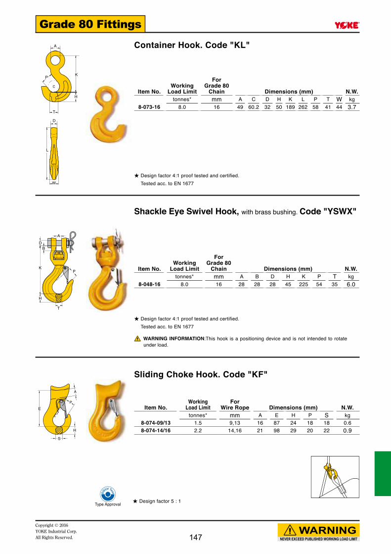
A
DB
K
H
T
P
T
H
C
A
KP
L
W
D
E
S
H
P
A
NEVER EXCEED PUBLISHED WORKING LOAD LIMIT
WARNINGCopyright © 2016 YOKE Industrial Corp.All Rights Reserved.
Grade 80 Fittings
Container Hook. Code "KL"
Shackle Eye Swivel Hook, with brass bushing. Code "YSWX"
Item No.Working
Load Limit
ForGrade 80
Chain Dimensions (mm) N.W.tonnes* mm A B D H K P T kg
8-048-16 8.0 16 28 28 28 45 225 54 35 6.0
Sliding Choke Hook. Code "KF"
Item No.Working
Load LimitFor
Wire Rope Dimensions (mm) N.W.tonnes* mm A E H P S kg
8-074-09/13 1.5 9,13 16 87 24 18 18 0.68-074-14/16 2.2 14,16 21 98 29 20 22 0.9
★ Design factor 4:1 proof tested and certified. Tested acc. to EN 1677
★ Design factor 4:1 proof tested and certified. Tested acc. to EN 1677
★ Design factor 5 : 1
Item No.Working
Load Limit
ForGrade 80
Chain Dimensions (mm) N.W.tonnes* mm A C D H K L P T W kg
8-073-16 8.0 16 49 60.2 32 50 189 262 58 41 44 3.7
WARNING INFORMATION:This hook is a positioning device and is not intended to rotate under load.
147

A
K
K
C
T
P
K
W
E
W
K
NEVER EXCEED PUBLISHED WORKING LOAD LIMIT
WARNINGCopyright © 2016
YOKE Industrial Corp.All Rights Reserved.
Grade 80 Fittings
Item No.Working
Load Limit
ForGrade 80
Chain Dimensions (mm) N.W.tonnes* mm A C K kg
8-063-07 2.0 7, 8 32 19 95 0.48-063-10 3.15 10 41 21 116 0.88-063-13 5.3 13 50 27 150 2.08-063-16 8.0 16 67 32 185 3.1
Item No.Working
Load Limit
ForGrade 80
Chain Dimensions (mm) N.W.tonnes* mm E K W kg
8-071-07 1.6 7, 8 38 133 50 0.9
Item No.Working
Load LimitFor
Wire Rope Dimensions (mm) N.W.tonnes* mm K P T W kg
8-076-0.5 0.5 8 72 19 12 18 0.48-076-01 1.0 13 72 19 20 18 0.58-076-02 2.0 16 89 19 28 26 1.18-076-04 4.0 20 109 25 32 34 1.9
Twist Eye Choke Hook. Code "KE"
Rapid Double End Choker. Code "KS"
Barrel Hook. Code "KK"
★ Design factor 4:1 proof tested and certified. Tested acc. to EN 1677
★ Design factor 4:1 proof tested and certified.
★ Design factor 5:1 proof tested and certified.
148

D
L
KM
T
P
H
A
D
C
T
B
K
H
NEVER EXCEED PUBLISHED WORKING LOAD LIMIT
WARNINGCopyright © 2016 YOKE Industrial Corp.All Rights Reserved.
Grade 80 Fittings
Item No.Working
Load Limit
ForGrade 80
Chain Dimensions (mm) N.W.tonnes* mm D H K L M P T dmin** kg
8-045-10 3.15 10 35 43 211 46 140 42 32 M20 1.6
Shank Sling Hook. Code "FH"
Tractor Hook. Code "FG"
Super Lock Hook
**d min.: the smallest shank dimension after machining.Note: After machining the shank proof loading must be carried out.★ Design factor 4:1
★ Design factor 4:1 proof tested and certified.
★ Design factor 5:1 proof tested and certified.
Item No.Working
Load Limit Dimensions (mm) N.W.tonnes* A B K L P T kg
8-092-38 8.5 32 43 183 265 30 42 5.68-092-45 11 32 43 215 300 34 46 7.0
Item No.Working
Load Limit Dimensions (mm) N.W.tonnes* A B C D H K P T kg
8-019-02 2 32 177 41 16 30 290 108 29 3.58-019-03 3 32 177 41 16 30 290 108 29 3.5
149

A
BOL
C
W
OL
W
D
C
B
E
F
P
G
A
K
H
T
D
NEVER EXCEED PUBLISHED WORKING LOAD LIMIT
WARNINGCopyright © 2016
YOKE Industrial Corp.All Rights Reserved.
Grade 80 Fittings
Item No.Working
Load Limit
ForGrade 80
Chain Dimensions (mm) N.W.tonnes* mm A B C W OL kg
8-080-06 1.12 6 22 120 32 55 143 0.68-080-07 2.0 7, 8 29 140 36 60 165 0.88-080-10 3.15 10 35 166 40 73 198 1.48-080-13 5.3 13 43 212 45 88 254 3.08-080-16 8.0 16 50 250 60 107 296 4.68-080-20 12.5 18, 20 82 337 74 128 387 7.68-080-22 15.0 22 95 412 97 168 478 15.78-080-26 21.2 26 115 519 122 211 602 37.5
Item No.Working
Load Limit
For Grade 80
Chain Dimensions (mm) N.W.tonnes* mm B C D E F W OL kg
8-089-10 3.15 10 80 41 30 2.5 25 69 115 0.78-089-13 5.3 13 95 48 36 2.5 30 81 135 1.28-089-16 8.0 16 108 50 42 2.5 36 97 155 2.0
Item No.Working
Load Limit
For Grade 80
Chain Dimensions (mm) N.W.tonnes* mm A D G H K P T kg
8-093-10 3.15 10 32 15 20 23 75 12 21 0.48-093-13 5.3 13 38 18 28 28 93 14 25 0.98-093-16 8.0 16 50 22 32 34 118 17 32 1.78-093-19 11.5 19 59 26 38 44 144 21 37 3.3
Eye Swivels
Quick Connector. Code "EM"
Quick Hook. Code "FA"
★ Design factor 4:1 proof tested and certified. Tested acc. to EN 1677
★ Design factor 4:1 proof tested and certified.
★ Design factor 4:1 proof tested and certified.
WARNING INFORMATION:This hook is a positioning device and is not intended to rotate under load.
150

Copyright © 2016YOKE Industrial Corp.All Rights Reserved. 151
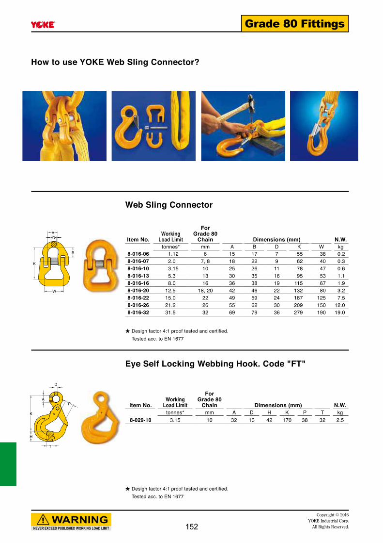
AD
K
W
B
D
A
K
H
T
P
NEVER EXCEED PUBLISHED WORKING LOAD LIMIT
WARNINGCopyright © 2016
YOKE Industrial Corp.All Rights Reserved.
Grade 80 Fittings
How to use YOKE Web Sling Connector?
Web Sling Connector
Eye Self Locking Webbing Hook. Code "FT"
★ Design factor 4:1 proof tested and certified. Tested acc. to EN 1677
★ Design factor 4:1 proof tested and certified. Tested acc. to EN 1677
Item No.Working
Load Limit
ForGrade 80
Chain Dimensions (mm) N.W.tonnes* mm A B D K W kg
8-016-06 1.12 6 15 17 7 55 38 0.28-016-07 2.0 7, 8 18 22 9 62 40 0.38-016-10 3.15 10 25 26 11 78 47 0.68-016-13 5.3 13 30 35 16 95 53 1.18-016-16 8.0 16 36 38 19 115 67 1.98-016-20 12.5 18, 20 42 46 22 132 80 3.28-016-22 15.0 22 49 59 24 187 125 7.58-016-26 21.2 26 55 62 30 209 150 12.08-016-32 31.5 32 69 79 36 279 190 19.0
Item No.Working
Load Limit
ForGrade 80
Chain Dimensions (mm) N.W.tonnes* mm A D H K P T kg
8-029-10 3.15 10 32 13 42 170 38 32 2.5
152
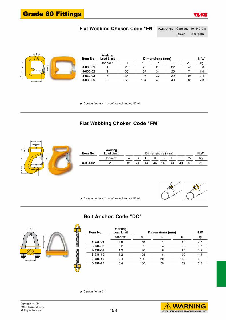
K
T
H
W
P
AD
B
K
H
T
W
P
K
A
D
NEVER EXCEED PUBLISHED WORKING LOAD LIMIT
WARNINGCopyright © 2016 YOKE Industrial Corp.All Rights Reserved.
Grade 80 Fittings
Flat Webbing Choker. Code "FN"
Flat Webbing Choker. Code "FM"
Bolt Anchor. Code "DC"
Patent■No. : Germany 40144213.8 Taiwan 90301916
★ Design factor 4:1 proof tested and certified.
★ Design factor 4:1 proof tested and certified.
★ Design factor 5:1
Item No.Working
Load Limit Dimensions (mm) N.W.tonnes* H K P T W kg
8-030-01 1 26 79 28 22 45 0.88-030-02 2 35 87 34 25 71 1.68-030-03 3 38 96 37 29 104 2.48-030-05 5 50 154 40 40 185 7.3
Item No.Working
Load Limit Dimensions (mm) N.W.tonnes* A B D H K P T W kg
8-031-02 2.0 81 24 14 44 140 44 40 80 2.2
Item No.Working
Load Limit Dimensions (mm) N.W.tonnes* A D K kg
8-036-05 2.5 55 14 59 0.78-036-06 3.2 65 14 75 0.78-036-07 4.2 80 16 85 1.28-036-10 4.2 105 16 109 1.48-036-12 6.4 132 20 135 2.28-036-15 6.4 160 20 172 3.2
153

W
K
H
T
P
NEVER EXCEED PUBLISHED WORKING LOAD LIMIT
WARNINGCopyright © 2016
YOKE Industrial Corp.All Rights Reserved.
Grade 80 Fittings
Round Sling Self Locking Hook
★ Design factor 4:1 proof tested and certified.
Item No.Working
Load Limit
ForGrade 80
Chain Dimensions (mm) N.W.tonnes* mm H K P T W kg
8-028-06 1.12 6 19 138 29 15 38 0.68-028-07 2.0 7, 8 24 169 34 20 40 1.18-028-10 3.15 10 30 196 44 26 47 1.88-028-13 5.3 13 39 253 52 30 53 3.78-028-16 8.0 16 49 305 60 36 67 7.08-028-20 12.5 18, 20 62 328 90 48 80 11.08-028-22 15.0 22 63 416 80 49 125 17.08-028-26 21.2 26 69 459 99 56 150 25.0
YOKE Roundsling Self Locking Hook is designed in a way to solve your synthetic end-fitting problems. The Roundsling Self Locking Hook presents following utmost benefits :1. The Round Shape is designed to provide great protection to your synthetic roundsling on everyloading.2. Offer complete range of hooks from 1 tonnes up to 21.2 tonnes.3. Assembly is fast and easy with only a hammer required.4. The hook with Self■Locking■function meets
real safe and safer required.5. Acquired certificate approved by BG
German company.
154

D
H
KP
T
B
W
D
H
KP
T
B
W
H
T
PK
D
B
w
H
T
PK
D
B
w
T
H
w
K
D
B
P
NEVER EXCEED PUBLISHED WORKING LOAD LIMIT
WARNINGCopyright © 2016 YOKE Industrial Corp.All Rights Reserved.
Grade 80 FittingsShackle Swivel Self Hook. Code "EH"with Brass Bushing
Shackle Swivel Self Hook. Code " EHN "with Ball Bearing, which performs full swivel under load
Shackle Swivel Hook. Code " EHY "with Brass Bushing
Shackle Swivel Hook. Code " EHYN " with Ball Bearing, which performs full swivel swivel under load
★ Design factor 4:1 proof tested and certified. Tested acc. to EN 1677
★ Design factor 4:1 proof tested and certified. Tested acc. to EN 1677
★ Design factor 4:1 proof tested and certified. Tested acc. to EN 1677
★ Design factor 4:1 proof tested and certified. Tested acc. to EN 1677
Item No.Working
Load Limit
Synthetic RopeSize Dimensions (mm) N.W.
tonnes* mm B D H K P T W kg8-020-07 2.0 14-16 45 19 24 204 34 20 21 1.58-020-10 3.15 18-20 60 20 30 243 44 27 27 2.78-020-13 5.3 22-27 75 22 39 307 51 33 34 5.2
Item No.Working
Load Limit
Synthetic RopeSize Dimensions (mm) N.W.
tonnes* mm B D H K P T W kg8-021-07 2.0 14-16 45 19 22 172 26 18 21 1.38-021-10 3.15 18-20 60 20 28 214 36 23 27 2.48-021-13 5.3 22-27 75 22 37 265 42 28 34 4.4
Item No.Working
Load Limit
Synthetic RopeSize Dimensions (mm) N.W.
tonnes* mm B D H K P T W kg8-021N-07 2.0 14-16 45 19 22 172 26 18 21 1.38-021N-10 3.15 18-20 60 20 28 214 36 23 27 2.48-021N-13 5.3 22-27 75 22 37 265 42 28 34 4.4
Item No.Working
Load Limit
Synthetic RopeSize Dimensions (mm) N.W.
tonnes* mm B D H K P T W kg8-020N-07 2.0 14-16 45 19 24 204 34 20 21 1.48-020N-10 3.15 18-20 60 20 30 243 44 27 27 2.88-020N-13 5.3 22-27 75 22 39 307 51 33 34 5.3
WARNING INFORMATION:This hook is a positioning device and is not intended to rotate under load. For swivel hooks designed to rotate under load, see p.147 8-020N.
WARNING INFORMATION:This hook is a positioning device and is not intended to rotate under load. For swivel hooks designed to rotate under load, see p.147 8-021N.
155

NEVER EXCEED PUBLISHED WORKING LOAD LIMIT
WARNINGCopyright © 2016
YOKE Industrial Corp.All Rights Reserved.
Grade 80 Fittings
1000 Volts Resistance
156
YOKE Insulation Solution
● YOKE Insulated Swivel is designed for winch protection in overhead crane during welding operations.
● Heavy hoisting with a strong but lightweight system.
● Individual swivels & components are 100% proof load tested to a minimum of 2.5 times the working load limit.
● All Swivels are individually tested during manufacturing to assure 1000 Volts insulating property. Test certificate is packaged with each unit shipped.
● YOKE Insulated Swivels are designed with ball bearing which performs to fully swivel under Load.
● Acquired certificate approved by Deutsche Gesetzliche Unfallversicherung (DGUV) .
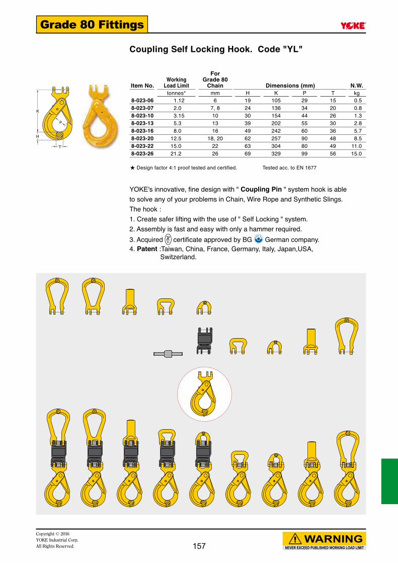
K
H
T
NEVER EXCEED PUBLISHED WORKING LOAD LIMIT
WARNINGCopyright © 2016 YOKE Industrial Corp.All Rights Reserved.
Grade 80 Fittings
Coupling Self Locking Hook. Code "YL"
Item No.Working
Load Limit
ForGrade 80
Chain Dimensions (mm) N.W.tonnes* mm H K P T kg
8-023-06 1.12 6 19 105 29 15 0.58-023-07 2.0 7, 8 24 136 34 20 0.88-023-10 3.15 10 30 154 44 26 1.38-023-13 5.3 13 39 202 55 30 2.88-023-16 8.0 16 49 242 60 36 5.78-023-20 12.5 18, 20 62 257 90 48 8.58-023-22 15.0 22 63 304 80 49 11.08-023-26 21.2 26 69 329 99 56 15.0
YOKE's innovative, fine design with " Coupling Pin " system hook is able to solve any of your problems in Chain, Wire Rope and Synthetic Slings. The hook :1. Create safer lifting with the use of " Self Locking " system.2. Assembly is fast and easy with only a hammer required.3. Acquired certificate approved by BG German company.4. Patent :Taiwan, China, France, Germany, Italy, Japan,USA,
Switzerland.
★ Design factor 4:1 proof tested and certified. Tested acc. to EN 1677
157

WT
H
K
A
L
D
WT
H
LK
NEVER EXCEED PUBLISHED WORKING LOAD LIMIT
WARNINGCopyright © 2016
YOKE Industrial Corp.All Rights Reserved.
Grade 80 Fittings
Insulated Blank Swivels. Code " BSI "with Ball BearingIndividually tested to resist 1000 Volts insulated with Test Certificate.Design for protection of overhead crane during welding operations on suspended loads.
Coupling Master Link. Code "EC"
Closed Coupling Master Link. Code "ECO"
★ Design factor 4:1 proof tested and certified. Tested acc. to EN 1677
★ Design factor 4:1 proof tested and certified. Tested acc. to EN 1677
★ Design factor 4:1 proof tested and certified. Tested acc. to EN 1677
Item No.Working
Load Limit
ForGrade 80
Chain Dimensions (mm) N.W.tonnes* mm D L kg
8-088-07 2.0 7, 8 50 75 0.68-088-10 3.15 10 62 94 1.28-088-13 5.3 13 77 123 2.48-088-16 8.0 16 94 143 4.28-088-20 12.5 18, 20 109 164 6.7
Item No.Working
Load Limit
ForGrade 80
Chain Dimensions (mm) N.W.tonnes* mm A H K T W kg
8-051-07 2.0 7, 8 15 15 100 15 50 0.38-051-10 3.15 10 19 19 127 19 66 0.68-051-13 5.3 13 25 22 145 23 72 1.08-051-16 8.0 16 30 26 174 25 80 1.68-051-20 12.5 18, 20 36 36 202 31 104 2.8
Item No.Working
Load Limit
ForGrade 80
Chain Dimensions (mm) N.W.tonnes* mm H K L T W kg
8-052-07 2.0 7, 8 15 100 78 15 50 0.38-052-10 3.15 10 19 127 101 19 65 0.78-052-13 5.3 13 22 145 113 23 72 1.18-052-16 8.0 16 26 174 137 25 80 1.78-052-20 12.5 18, 20 36 202 165 31 104 3.0
1000 Volts Resistance
158

K
H
T
P
D
L1
L2
W
NEVER EXCEED PUBLISHED WORKING LOAD LIMIT
WARNINGCopyright © 2016 YOKE Industrial Corp.All Rights Reserved.
Grade 80 Fittings
Shank Coupling. Code "EA"
Coupling Sling Hook. Code "EB"
Round Sling Coupling. Code "YW"
** d min.: the smallest shank dimension after machining. Note: After machining the shank, proof loading must be carried out.
★ Design factor 4:1 proof tested and certified. Tested acc. to EN 1677
★ Design factor 4:1 proof tested and certified.
Item No.Working
Load Limit
ForGrade 80
Chain Dimensions (mm) N.W.tonnes* mm D d min.** L1 L2 kg
8-050-07 2.0 7, 8 30 13 69 30 0.58-050-10 3.15 10 35 16 70 32 0.78-050-13 5.3 13 42 20 105 39 1.68-050-16 8.0 16 50 25 120 46 2.68-050-20 12.5 18, 20 75 30 90 59 5.6
Item No.Working
Load Limit
ForGrade 80
Chain Dimensions (mm) N.W.tonnes* mm H K P T kg
8-055-07 2.0 7, 8 23 93 30 19 0.48-055-10 3.15 10 31 115 36 23 0.98-055-13 5.3 13 36 141 42 28 1.88-055-16 8.0 16 45 166 47 32 3.08-055-20 12.5 18, 20 48 191 52 43 4.7
Item No.Working
Load Limit
ForGrade 80
Chain Dimensions (mm) N.W.tonnes* mm A B K W kg
8-053-06 1.12 6 15 22 33 38 0.28-053-07 2.0 7, 8 18 24 33 40 0.28-053-10 3.15 10 25 29 42 47 0.48-053-13 5.3 13 30 35 51 53 0.78-053-16 8.0 16 36 44 63 67 1.38-053-20 12.5 18, 20 42 52 71 80 2.18-053-22 15.0 22 49 72 112 125 5.78-053-26 21.2 26 55 84 130 150 9.08-053-32 31.5 32 69 85 165 190 14.0
159

D
K L
A
NEVER EXCEED PUBLISHED WORKING LOAD LIMIT
WARNINGCopyright © 2016
YOKE Industrial Corp.All Rights Reserved.
Grade 80 Fittings
Half Coupling Link. Code "BST"with Coupling Pin and Sleeve Locking
★ Design factor 4:1 proof tested and certified. Tested acc. to EN 1677
Item No.Working
Load Limit
ForGrade 80
Chain Dimensions (mm) N.W.tonnes* mm A D K L kg
8-054-06 1.12 6 15 7 17 22 0.18-054-07 2.0 7, 8 18 9 22 28 0.18-054-10 3.15 10 25 11 26 34 0.28-054-13 5.3 13 30 16 35 45 0.48-054-16 8.0 16 36 19 38 50 0.68-054-20 12.5 18, 20 42 22 46 60 1.18-054-22 15.0 22 49 24 59 76 1.78-054-26 21.2 26 55 30 62 80 2.78-054-32 31.5 32 69 36 79 100 5.0
160

D
L1
L
H
T
L1
D
L
HT
AD
L
H
T
NEVER EXCEED PUBLISHED WORKING LOAD LIMIT
WARNINGCopyright © 2016 YOKE Industrial Corp.All Rights Reserved.
Grade 80 FittingsInsulated Swivelswith Shank & Coupling Sling Hook
Insulated Swivelswith Shank & Coupling Self Locking Hook
Insulated Swivelswith Half Link & Coupling Self Locking Hook
Item No.Working
Load Limit
ForGrade 80
Chain Dimensions (mm) N.W.tonnes* mm D H L L1 T kg
8-132-07 2.0 7, 8 30 23 266 69 19 1.88-132-10 3.15 10 35 31 310 70 23 2.98-132-13 5.3 13 42 36 409 105 28 5.88-132-16 8.0 16 50 45 474 120 32 12.08-132-20 12.5 18, 20 75 48 502 90 43 17.1
Item No.Working
Load Limit
ForGrade 80
Chain Dimensions (mm) N.W.tonnes* mm D H L L1 T kg
8-121-07 2.0 7, 8 30 24 310 69 20 2.48-121-10 3.15 10 35 30 350 70 26 4.88-121-13 5.3 13 42 39 470 105 30 8.08-121-16 8.0 16 50 49 551 120 36 24.08-121-20 12.5 18, 20 75 62 568 90 48 22.0
Item No.Working
Load Limit
ForGrade 80
Chain Dimensions (mm) N.W.tonnes* mm A D H L T kg
8-122-07 2.0 7, 8 18 9 24 239 20 1.58-122-10 3.15 10 25 11 30 282 26 2.88-122-13 5.3 13 30 16 39 371 30 5.78-122-16 8.0 16 36 19 49 435 36 11.08-122-20 12.5 18, 20 42 22 62 482 48 15.9
★ Design factor 4:1 proof tested and certified
★ Design factor 4:1 proof tested and certified
★ Design factor 4:1 proof tested and certified Tested acc. to EN 1677
1000 Volts Resistance
1000 Volts Resistance
1000 Volts Resistance
161

L
AD
L
W
HT
t
Wt
L
H
T
NEVER EXCEED PUBLISHED WORKING LOAD LIMIT
WARNINGCopyright © 2016
YOKE Industrial Corp.All Rights Reserved.
Grade 80 Fittings
Insulated Swivelswith 2 Half Links
Insulated Swivelswith Open Master Link & Coupling Self Locking Hook
Insulated Swivelswith Open Master Link & Sling Hook
★ Design factor 4:1 proof tested and certified Tested acc. to EN 1677
★ Design factor 4:1 proof tested and certified Tested acc. to EN 1677
★ Design factor 4:1 proof tested and certified Tested acc. to EN 1677
Item No.Working
Load Limit
ForGrade 80
Chain Dimensions (mm) N.W.tonnes* mm A D L kg
8-123-07 2.0 7, 8 18 9 131 0.78-123-10 3.15 10 25 11 162 1.58-123-13 5.3 13 30 16 214 3.28-123-16 8.0 16 36 19 243 5.48-123-20 12.5 18, 20 42 22 285 9.0
Item No.Working
Load Limit
ForGrade 80
Chain Dimensions (mm) N.W.tonnes* mm H L T W t kg
8-124-07 2.0 7, 8 24 310 20 50 15 1.88-124-10 3.15 10 30 374 26 65 19 3.38-124-13 5.3 13 39 471 30 72 23 6.78-124-16 8.0 16 49 560 36 80 25 12.08-124-20 12.5 18, 20 62 624 48 104 31 18.0
Item No.Working
Load Limit
ForGrade 80
Chain Dimensions (mm) N.W.tonnes* mm H L T W t kg
8-125-07 2.0 7, 8 23 267 19 50 15 1.38-125-10 3.15 10 31 335 23 65 19 3.08-125-13 5.3 13 36 410 28 72 23 5.58-125-16 8.0 16 45 484 32 80 25 9.58-125-20 12.5 18, 20 48 558 43 104 31 14.7
1000 Volts Resistance
1000 Volts Resistance
1000 Volts Resistance
162

wt
L
DA
W
D
P K
D
K
H
WT
Item No. Working
Load Limit
ForGrade 80
Chain Dimensions(mm) N.W.tonnes* mm L A D W t kg
8-126-07 2.0 7, 8 202 18 9 50 15 1.68-126-10 3.15 10 255 25 11 65 19 2.18-126-13 5.3 13 313 30 16 72 23 4.08-126-16 8.0 16 368 36 19 80 25 6.78-126-20 12.5 18, 20 427 42 22 104 31 12.0
Item No. Working
Load Limit
ForGrade 80
Chain Dimensions(mm) N.W.tonnes* mm D H K T W kg
8-128-07 2.0 7, 8 9 15 121 15 50 0.48-128-10 3.15 10 11 19 149 19 65 0.88-128-13 5.3 13 16 22 187 23 72 1.88-128-16 8.0 16 19 26 216 25 80 2.48-128-20 12.5 18, 20 22 36 252 31 104 4.8
Item No. Working
Load Limit
ForGrade 80
Chain Dimensions(mm) N.W.tonnes* mm D K P W kg
8-130-07 2.0 7, 8 9 136 76 40 0.88-130-10 3.15 10 11 170 94 47 1.88-130-13 5.3 13 16 219 123 53 3.68-130-16 8.0 16 19 256 142 67 6.58-130-20 12.5 18, 20 22 295 164 80 10.1
NEVER EXCEED PUBLISHED WORKING LOAD LIMIT
WARNINGCopyright © 2016 YOKE Industrial Corp.All Rights Reserved.
Grade 80 Fittings
Insulated Swivelswith Open Master Link & Half Link
Insulated Swivelswith Half Link & Web Sling Connector
Open Master Link with Half Link
★ Design factor 4:1 proof tested and certified Tested acc. to EN 1677
★ Design factor 4:1 proof tested and certified
★ Design factor 4:1 proof tested and certified Tested acc. to EN 1677
1000 Volts Resistance
1000 Volts Resistance
163

WT
H
K
D
D
K
H
T
P
W
t
K
H
T
Item No. Working
Load Limit
ForGrade 80
Chain Dimensions(mm) N.W.tonnes* mm D H K T W kg
8-129-07 2.0 7, 8 9 15 121 15 50 0.48-129-10 3.15 10 11 19 149 19 65 0.98-129-13 5.3 13 16 22 187 23 72 1.38-129-16 8.0 16 19 26 216 25 80 2.48-129-20 12.5 18, 20 22 36 252 31 104 4.8
Item No. Working
Load Limit
ForGrade 80
Chain Dimensions(mm) N.W.tonnes* mm D H K P T kg
8-131-07 2.0 7, 8 9 23 123 30 19 0.68-131-10 3.15 10 11 31 149 36 23 1.18-131-13 5.3 13 16 36 187 42 28 2.28-131-16 8.0 16 19 45 216 47 32 3.78-131-20 12.5 18, 20 22 48 252 52 43 6.0
Item No. Working
Load Limit
ForGrade 80
Chain Dimensions(mm) N.W.tonnes* mm H K T t W kg
8-127-07 2.0 7, 8 24 228 20 15 50 1.28-127-10 3.15 10 30 268 26 19 65 2.18-127-13 5.3 13 39 343 30 23 72 4.08-127-16 8.0 16 49 408 36 25 80 7.78-127-20 12.5 18, 20 62 448 48 31 104 11.6
NEVER EXCEED PUBLISHED WORKING LOAD LIMIT
WARNINGCopyright © 2016
YOKE Industrial Corp.All Rights Reserved.
Grade 80 Fittings
Closed Master Link with Half Link
Sling Hook with Half Link
Coupling Self Locking Hook with Open Master Link
★ Design factor 4:1 proof tested and certified Tested acc. to EN 1677
★ Design factor 4:1 proof tested and certified Tested acc. to EN 1677
★ Design factor 4:1 proof tested and certified Tested acc. to EN 1677
164

Item No. Tap Size Dimensions (inch) N.W.A B D H J K W lbs
8-9400-05 No.10 — 32UNF 0.20 0.45 0.32 0.57 0.19 1.03 0.37 0.028-9400-06 1/ 4 — 28UNF 0.29 0.63 0.42 0.75 0.25 1.25 0.19 0.078-9400-08 5/16 — 24UNF 0.35 0.76 0.50 0.81 0.31 1.44 0.60 0.118-9400-10 3/ 8 — 24UNF 0.44 0.88 0.63 0.87 0.37 1.63 0.69 0.188-9400-11 7/16 — 20UNF 0.50 1.01 0.72 0.99 0.44 1.89 0.81 0.268-9400-13 1/ 2 — 20UNF 0.56 1.13 0.81 1.11 0.50 1.89 0.94 0.358-9400-16 5/ 8 — 18UNF 0.69 1.38 1.06 1.20 0.63 3.73 1.19 0.86
NEVER EXCEED PUBLISHED WORKING LOAD LIMIT
WARNINGCopyright © 2016 YOKE Industrial Corp.All Rights Reserved.
Grade 80 Fittings
165
A
Tap Size
K
H
D
W
J
B
Item No. Tap Size Dimensions (mm) N.W.A B D H J K W kg
8-9400-05 No.10 — 32UNF 5 11 8 14 5 26 9 0.018-9400-06 1/ 4 — 28UNF 7 16 11 19 6 32 12 0.038-9400-08 5/16 — 24UNF 9 19 13 21 8 37 15 0.058-9400-10 3/ 8 — 24UNF 11 22 16 22 10 41 18 0.088-9400-11 7/16 — 20UNF 13 26 18 25 11 48 21 0.128-9400-13 1/ 2 — 20UNF 14 29 21 28 13 48 24 0.168-9400-16 5/ 8 — 18UNF 17 35 27 31 16 95 30 0.39
Yoke End (clevis end)Threaded
● Forged, low carbon steel.
● Adjustable Yoke End (also) called "clevis ends" are typically assembled to the end of a rod, pope, tube or cable linkage and are then attached via a clevis pin to a mounting point.

Copyright © 2016YOKE Industrial Corp.All Rights Reserved. 166
Designed and Manufacturedaccording to
API Spec 8C
8C-0283
RFF TM RingForged-Fabricated TM
Heavy Duty Oilfield Sheave

NEVER EXCEED PUBLISHED WORKING LOAD LIMIT
WARNINGCopyright © 2016 YOKE Industrial Corp.All Rights Reserved. 167
8C-0283
YOKE INDUSTRIAL CORP.No. 39, 33rd Road Taichung Industrial Park
TaichungTaiwan
API-8C
8C-0283
The scope of this license includes the following: Hoisting Sheaves at PSL 1, PSL 2
QMS Exclusions: No Exclusions Identified as Applicable
Effective Date:Expiration Date:
JANUARY 8, 2015MARCH 30, 2018
Feb 1st, 2015
YOKE Industrial Corporation of Taiwan are pleased to announce that following significant capital investment in Taichung manufacturing facility, that we have been awarded API 8C certification for the manufacture of large diameter heavy duty oilfield sheave. Steven Hong, Chairman of YOKE said " I am very proud of all our employees who have all worked extremely hard to achieve API 8C certification, whilst continuing to maintain our API Q1 facility, particularly the design, engineering and manufacturing people, On our 30 year anniversary this year in 2015, it is a significant milestone, being one of only a few global sheave manufacturers who have the technical and manufacturing capabilities to manufacture RFFTM RingForged-FabricatedTM Heavy Duty Oilfield Sheaves for the ever increasing demands of the energy industry."
YOKE continues to invest in advanced manufacturing techniques in order to meet our partners demands for high performance sheaves used in Drilling Blocks, Travelling Blocks, Tubing Blocks, Crown Blocks, Draw Works, Diverters and Motion Compensation sheaves both on Drill Ships, Land and Offshore Drilling Rigs and other energy related applications. YOKE's investment in capital equipment in 2014, a project to manufacture and supply large diameter RFFTM RingForged-FabricatedTM Heavy Duty Oilfield Sheaves by early 2015 came to its pinnacle this month, with the award of the API 8C certification.YOKE's geographic manufacturing location close to many of the major drill ship and oil rig fabrication yards greatly reduces the lead time faced by many of its competitors. YOKE will work closely with its WDC and OEM partners to ensure that its range of API 8C sheaves are available in all the major energy related hubs around the globe.
This capital investment in larger diameter API 8C sheaves enhances YOKE's current range of YSB Snatch blocks and forged sheaves which already form a major section of their product offering of chain and wire rope fittings. YOKE continues to expand its range of material handling and lifting products in order to become the partner of choice in the energy industry.
YOKE also offers third party type approval on the range of YOKE RFFTM RingForged-FabricatedTM Heavy Duty Oilfield Sheaves, such as DNV, ABS, LRS and other major organizations.
A Grand Announcement ofRFFTM RingForged-FabricatedTM Sheave
by YOKE

NEVER EXCEED PUBLISHED WORKING LOAD LIMIT
WARNINGCopyright © 2016
YOKE Industrial Corp.All Rights Reserved.168
YOKE RFFTM RingForged-FabricatedTM sheave offers maximum strength with minimum weight, utilizing the advanced manufacturing techniques, it has developed for YOKE RFFTM RingForged-FabricatedTM sheave program for ultimate performance in the field. Full penetration robot welding, stress relieving, groove profiling and hardening, balancing and final coating means that YOKE can offer a short lead time, for both of the shelf sheaves and customer designed, equipped with or without high performance bearings. YOKE's design of RFFTM RingForged-FabricatedTM sheaves enables them to offer other benefits, such as increased rim wall thickness for large fleet angles, different levels of groove depth and hardness without having to sacrifice an increase in total sheave weight. YOKE Engineering can use modeling to develop the best mix of rim, web and hub to suit the application minimizing the weight but maintaining the strength, integrity and performance expected of a YOKE RFFTM RingForged-FabricatedTM sheave. This unique design offers a very competitive sheave and can enhance the lifetime performance.
8C-0283
The Features of YOKE
RFFTM RingForged-FabricatedTM Heavy Duty Oilfield Sheave
Groove angle Profile
API STYLE
Domed Type

NEVER EXCEED PUBLISHED WORKING LOAD LIMIT
WARNINGCopyright © 2016 YOKE Industrial Corp.All Rights Reserved. 169
The Specification of YOKE
RFFTM RingForged-FabricatedTM Sheave
(Under Development)
* YOKE RFFTM RingForged-FabricatedTM Sheave Production on Demand.
* For further detail in engineering services, please contact
YOKE RFFTM Engineered Product Group at [email protected]
Nominal OutsideDiameter
(inch)
Wire Line Size(inch)
42 1-1/8 1-1/4
48 1-1/8 1-1/4
52 1-3/4
60 1-3/8 1-1/2 1-5/8
72 1-3/4 2 2-1/4
78 1-3/4 2 2-1/4
90 2-1/2 2-3/4

NEVER EXCEED PUBLISHED WORKING LOAD LIMIT
WARNINGCopyright © 2016
YOKE Industrial Corp.All Rights Reserved.170
RFFTM RingForged-FabricatedTM
Heavy Duty Domed Crown Oilfield Sheave

NEVER EXCEED PUBLISHED WORKING LOAD LIMIT
WARNINGCopyright © 2016 YOKE Industrial Corp.All Rights Reserved. 171
RFFTM RingForged-FabricatedTM
Heavy Duty Web Oilfield Sheave
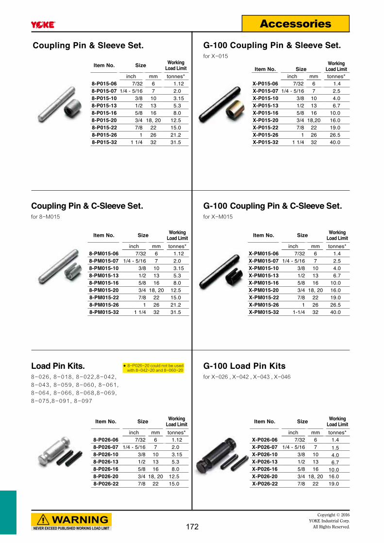
Item No. Size WorkingLoad Limit
inch mm tonnes* 8-P015-06 7/32 6 1.128-P015-07 1/4 - 5/16 7 2.08-P015-10 3/8 10 3.158-P015-13 1/2 13 5.38-P015-16 5/8 16 8.08-P015-20 3/4 18, 20 12.58-P015-22 7/8 22 15.08-P015-26 1 26 21.28-P015-32 1 1/4 32 31.5
Item No. Size WorkingLoad Limit
inch mm tonnes* 8-PM015-06 7/32 6 1.128-PM015-07 1/4 - 5/16 7 2.08-PM015-10 3/8 10 3.158-PM015-13 1/2 13 5.38-PM015-16 5/8 16 8.08-PM015-20 3/4 18, 20 12.58-PM015-22 7/8 22 15.08-PM015-26 1 26 21.28-PM015-32 1 1/4 32 31.5
Item No. Size WorkingLoad Limit
inch mm tonnes* X-PM015-06 7/32 6 1.4 X-PM015-07 1/4 - 5/16 7 2.5 X-PM015-10 3/8 10 4.0X-PM015-13 1/2 13 6.7X-PM015-16 5/8 16 10.0X-PM015-20 3/4 18, 20 16.0 X-PM015-22 7/8 22 19.0X-PM015-26 1 26 26.5X-PM015-32 1-1/4 32 40.0
Item No. SizeWorking
Load Limitinch mm tonnes*
X-P015-06 7/32 6 1.4X-P015-07 1/4 - 5/16 7 2.5X-P015-10 3/8 10 4.0X-P015-13 1/2 13 6.7X-P015-16 5/8 16 10.0X-P015-20 3/4 18,20 16.0X-P015-22 7/8 22 19.0X-P015-26 1 26 26.5X-P015-32 1 1/4 32 40.0
NEVER EXCEED PUBLISHED WORKING LOAD LIMIT
WARNINGCopyright © 2016
YOKE Industrial Corp.All Rights Reserved.
Accessories
Coupling Pin & Sleeve Set. G-100 Coupling Pin & Sleeve Set.for X-015
Coupling Pin & C-Sleeve Set.for 8-M015
G-100 Coupling Pin & C-Sleeve Set.for X-M015
Item No. Size WorkingLoad Limit
inch mm tonnes* 8-P026-06 7/32 6 1.128-P026-07 1/4 - 5/16 7 2.0 8-P026-10 3/8 10 3.158-P026-13 1/2 13 5.3 8-P026-16 5/8 16 8.08-P026-20 3/4 18, 20 12.58-P026-22 7/8 22 15.0
Item No. Size WorkingLoad Limit
inch mm tonnes* X-P026-06 7/32 6 1.4X-P026-07 1/4 - 5/16 7 1.5X-P026-10 3/8 10 4.0X-P026-13 1/2 13 6.7X-P026-16 5/8 16 10.0X-P026-20 3/4 18, 20 16.0X-P026-22 7/8 22 19.0
Load Pin Kits.8-026, 8-018, 8-022,8-042,
8-043, 8-059, 8-060, 8-061,
8-064, 8-066, 8-068,8-069,
8-075,8-091, 8-097
★ 8-P026-20 could not be used with 8-042-20 and 8-060-20
G-100 Load Pin Kitsfor X-026 , X-042 , X-043 , X-046
172

Item No. Sizetonnes*
8-P081-01 18-P081-02 28-P081-03 38-P081-04 48-P081-05 58-P081-08 88-P081-10 108-P081-15 15
Item No. SizeWorking
Load Limitinch mm tonnes*
8-P072-07 1/4 - 5/16 7 2.0 8-P072-10 3/8 10 3.15 8-P072-13 1/2 13 5.3 8-P072-16 5/8 16 8.0
Item No. Sizeinch mm
8-P044-06 7/32 68-P044-07 1/4 - 5/16 78-P044-10 3/8 108-P044-13 1/2 138-P044-16 5/8 16.08-P044-20 3/4 18, 208-P044-22 7/8 228-P044-26 1 268-P044-32 1 1/4 32
Item No. Sizeinch mm
8-P074-09/13 3/8 9,139/16 14,16
Item No. Sizeinch mm
8-P049-06 7/32 68-P049-07 1/4 - 5/16 78-P049-10 3/8 108-P049-13 1/2 138-P049-16 5/8 16.08-P049-20 3/4 18, 20
NEVER EXCEED PUBLISHED WORKING LOAD LIMIT
WARNINGCopyright © 2016 YOKE Industrial Corp.All Rights Reserved.
Accessories
Latch Kits.for 8-081
Latch Kits.for 8-921, 8-931
Load Pin Kits.for 8-072
Latch Kits.for 8-074
Latch Kits.for 8-044, 8-043, X-044, X-043
Latch Kits.for 8-049
Item No. Sizetonnes*
8-P921-03 38-P921-05 58-P921-07 78-P921-11 118-P921-15 158-P921-22 228-P921-30 30
173

Item No. Sizeinch mm
8-P025-06 7/32 68-P025-07 1/4-5/16 78-P025-10 3/8 108-P025-13 1/2 138-P025-16 5/8 168-P025-20 3/4 18,208-P025-22 7/8 228-P025-26 1 268-P025-28 1-1/1/8 28
Item No. SizeWorking
Load Limitinch mm tonnes*
8-P950-10 3/8 10 4.0 8-P950-13 1/2 13 6.7 8-P950-16 5/8 16 10.08-P950-20 3/4 20,22 16.0
**For G100 size 20mm: X-P025-20
NEVER EXCEED PUBLISHED WORKING LOAD LIMIT
WARNINGCopyright © 2016
YOKE Industrial Corp.All Rights Reserved.
Accessories
Trigger Kits for G80 and G100 Self Locking Hooks
Trigger Kits For Grip Self Locking HooksFor X-950, X-951, X-952N
New Trigger Kits for Self Locking Hooks size 20mm, 26mm, and 28mm after design change
G80 size 20mm Item No. Size
inch mm8-P025T-20 3/4 18,20
G80 and G100 size 26mm Item No. Size
inch mm8-P025T-26 1 26
G80 size 28mm Item No. Size
inch mm8-P025T-28 1-1/8 28
Width of the body increased, choose original trigger kits.
Triggers recessed, choose New trigger kits.
Type I
Before Change
Type II
After change
174

NEVER EXCEED PUBLISHED WORKING LOAD LIMIT
WARNINGCopyright © 2016 YOKE Industrial Corp.All Rights Reserved. 175
NOTE

NEVER EXCEED PUBLISHED WORKING LOAD LIMIT
WARNINGCopyright © 2016
YOKE Industrial Corp.All Rights Reserved.176
NOTE

NEVER EXCEED PUBLISHED WORKING LOAD LIMIT
WARNINGCopyright © 2016 YOKE Industrial Corp.All Rights Reserved. 177
NOTE

NEVER EXCEED PUBLISHED WORKING LOAD LIMIT
WARNINGCopyright © 2016
YOKE Industrial Corp.All Rights Reserved.178
NOTE
By Item. Number Code & Number
INDEX
Item No. Page8-003 1338-003F 1338-015 1358-016 1528-018 1358-019 1498-020 1558-020N 1558-021 1558-021N 1558-022 1388-023 1578-024 1378-025 1368-026 1368-027 1378-027N 1378-028 1548-029 1528-030 1538-031 1538-036 1538-039 1398-041 1428-042 1428-043/S 1408-044/S 1398-045 1498-047 1398-048 1478-049 1388-049N 1388-050 1598-051 1588-052 1588-053 1598-054 1608-055 1598-056 1348-057 668-0573 658-058 598-059 1348-060 1438-061 1428-062 1438-063 1488-064 1438-065 1448-066 1408-067 1468-068 1468-069 1468-071 1488-072 1458-073 1478-074 1478-075 141
Item No. Page8-076 1488-077 1448-078 1458-080 1508-081 648-082 678-088 1588-089 1508-091 1418-092 1498-093 1508-097 1408-098 608-121 1618-122 1618-123 1628-124 1628-125 1628-126 1638-127 1648-128 1638-129 1648-130 1638-131 1648-132 1618-171.SC 778-171.SC/0 77
8-173 79125
8-173/0 79
8-175 81125
8-175/0 81
8-175N 82125
8-175N/0 82
8-191.SC 78
8-191.SC/0 78
8-193 808-193/0 808-195 838-195/0 838-195N 848-195N/0 848-201 588-202 568-203 578-204 558-211 448-211/L 468-212 458-215 478-231 528-231/L 538-232 52
Item No. Page8-271 508-272 518-291 498-291K 488-292 498-292K 488-301 698-303 708-304 718-305 728-306 738-307 748-308 758-500 1068-501 908-502 918-503 928-504 1078-512 1088-514 1098-515 1108-521 1128-522 1138-523 1128-531 1148-532 1148-541 938-542 948-543 958-551 968-552 978-553 988-561 998-562 1008-563 1018-571 1028-572 1038-573 1048-591 1058-730 168-731 178-732 188-733 218-734 208-735 198-739.SC 228-739.SC/0 228-804 338-805 338-807 298-808 288-809 328-834 348-835 348-837 318-838 308-911 368-921 37
Item No. Page8-931 388-9400 1658-M015 1358-P015 1728-P025 1748-P026 1728-P044 1738-P049 1738-P072 1738-P074 1738-P081 1738-P211 448-P212 458-P801 858-P921 1738-P950 1748-PM015 1728-Tag 141X-003 121X-015 121X-016 130X-025 123X-026 123X-027 123X-027N 124X-028 130X-032 130X-041 126X-042 127X-0421 127X-043/S 124X-044/S 124X-046 126X-047 126X-059 131X-066 131X-077 127X-950 129X-951 129X-952N 129X-M015 121X-P015 172X-P025 174X-P026 172X-PM015 172901 26902 24903 24903Y 259041 259042 25DA-838 13DA-808 14
Code PageBSI 158BST 160DA 134DAA 66DAB 59DC 153EA 159EB 159EC 158ECO 158EF 144EH 155EHN 155EHY 155EHYN 155EL 139EM 150EX 145FA 150FE 140FG 149FH 149FM 153FN 153FT 152KA 146KB 146KC 143KCK 142KD 143KE 148KF 147KK 148KL 147KP 138KR 143KS 148KT 144KU 146MF 133MFF 133YA 135YC 136YD 136YE 137YEA 137
Code PageYEN 137YF 141YG 134YH 142YK 142YL 157YM 139YN 139YO 135YP 139YR 140YSW 138YSWN 138YSWX 147YT 141YW 159YX 64
Code Item No.BSI 8-088BST 8-054DA 8-056DAA 8-057DAB 8-058DC 8-036EA 8-050EB 8-055EC 8-051ECO 8-052EF 8-077EH 8-020EHN 8-020NEHY 8-021EHYN 8-021NEL 8-039EM 8-089EX 8-072FA 8-093FE 8-097FG 8-092FH 8-045FM 8-031FN 8-030FT 8-029KA 8-067KB 8-068KC 8-060KCK 8-061KD 8-062KE 8-063KF 8-074KK 8-071KL 8-073KP 8-022KR 8-064KS 8-076KT 8-065KU 8-069MF 8-003MFF 8-003FYA 8-015YC 8-025YD 8-026YE 8-027YEA 8-024
Code Item No.YEN 8-027NYF 8-091YG 8-059YH 8-041YK 8-042YL 8-023YM 8-043/SYN 8-047YO 8-018YP 8-044/SYR 8-066YSW 8-049YSWN 8-049NYSWX 8-048YT 8-075YW 8-053YX 8-081
NEVER EXCEED PUBLISHED WORKING LOAD LIMIT
WARNINGCopyright © 2016 YOKE Industrial Corp.All Rights Reserved. 179

www.yoke.net
An ISO 9001 Registered Company
TM Safety is our first priority
YOKE products distributed by:
General C
atalog No. 8-2016
YOKE INDUSTRIAL CORP. #39, 33rd Road,
Taichung Industrial Park, Taichung 407,
TAIWAN Tel:+886-4-2350-8088
Fax:+886-4-2350-1001 E-mail: [email protected]
Gen
eral
Cat
alog
No.
8-2
016/
1050
121/
210X
297
Eur
ope-
100
8-2016
TM Safety is our first priority
General Catalog No. 8-2016


