SPLIT AIR CONDITIONER WITH GAS FURNACE ® USER'S INFORMATION MANUAL (602) 943-3426 9828 North 19th Avenue Phoenix, AZ 85021-1992 www.ChasRoberts.com (520) 292-6858 4065 East Illinois Street Tucson, AZ 85714-2106
Transcript
SPLIT AIR CONDITIONER WITH GAS FURNACE
®
USER'SINFORMATION
MANUAL
(602) 943-3426
9828 North 19th AvenuePhoenix, AZ 85021-1992
www.ChasRoberts.com
(520) 292-6858
4065 East Illinois StreetTucson, AZ 85714-2106
Important Facts You Should Know AboutYour Gas Furnace and Air Conditioner
• If You Smell Gas – Call your gas company, at once, from a neighbor’s phone. DO NOT touch any electrical switches or light any flames.
• If Smoke Appears – Don’t be alarmed, THIS IS NORMAL, the first time the furnace is started. Your smoke alarms may sound, but they will reset when the smoke clears. The reason this happens is because the factory applies a layer of oil inside the furnace to protect it during shipment. The burners will burn away this oil the first time the furnace is started. The furnace will smoke this one time only.
• Before you call for service, check these simple items first:
• If you have checked all these things, and the furnace still does not operate, CALL your builder or Chas Roberts Air Conditioning.
• Important, more detailed information on your furnace should be reviewed in your homeowner’s operation and maintenance manual.
Is the furnace plugged in and are the breakers and disconnects turned on? Is the thermostat set above the room temperature? Is the thermostat switch set in the heat position: Is the gas line connected to the furnace? If not, call you builder or plumbing contractor. Is the gas manual shut off valve open? The gas valve handle is located just outside the furnace
and the handle should be turned parallel with the gas pipe to be on. If it is turned at a right angle, it is off.
Is the air filter dirty or full of lint? A dirty filter will block needed air flow to the furnace and shut it down prematurely.
• During the cooling season, your gas furnace provides air flow for your air conditioning.
• Do Not turn the air conditioning system off. Part-time cooling is poor economy. If the system is left off during the morning, the home will soak up heat and be more difficult to cool in the afternoon. You can actually save money by letting the thermostat determine when cooling is needed.
• During the hot, dry seasons, we recommend keeping the air conditioner blower on continuously. The air conditioning unit cools more evenly when the blower switch is in the ON position. The blower provides refreshing air movement and even temperatures throughout the home. The blower also circulates air through the filter, which helps remove dust, lint and other pollutants more efficiently.
• During the more humid monsoon season, we recommend switching the blower to the AUTO position to help dehumidify the air more efficiently. Check you condensate drain to make sure the moisture being removed from the house is draining properly. The bottom drain outside your house should be dripping and the emergency overflow drain above should be dry.
• Shades, drapes, shutters, or screens should be installed on windows that are exposed to direct sunlight. Also, plant a tress or put up a canopy to protect your windows from the direct sun.
• For cooling and heating . . . Leave your thermostat alone. When you have found a temperature that you prefer, it is best to leave the thermostat at that setting.
• Clean or replace the filters frequently. Dirty filters will lower performance and efficiency of your cooling. The filters are usually located at the return grille or at the indoor section of your unit.
Gas Furnace
Air Conditioner
(602) 943-3426 or (520) 292-6858www.ChasRoberts.com
126114-UUM-I-0608
USER’S INFORMATION MANUALOUTDOOR SPLIT-SYSTEM AIR CONDITIONERMODELS: 13, 14+ SEER SERIES 1 TO 5 TONS
LISTEDISO 9001
Certified QualityManagement System
This high efficiency air conditioning system has been precision engi-neered, manufactured of high quality materials, and passed many rigor-ous tests and inspections to ensure years of satisfactory service. That’swhy you can rely on efficient, trouble-free operation.Your system is fully automatic. Set the thermostat and forget it. And it’sautomatically protected from damage by voltage fluctuations or exces-sive heating or cooling demands.Your split system air conditioner consists of two units - one installed out-doors and one installed indoors. The indoor unit may be installed in abasement, attic, or crawl space.
HOW YOUR AIR CONDITIONER WORKSIf your hand is wet and you blow on it, it feels cool because some of themoisture is evaporating and becoming a vapor. This process requiresheat. The heat is being taken from your hand, so your hand feels cool.That’s what happens with an air conditioner. During the cooling cycle,your system will remove heat and humidity from your home and willtransfer this heat to the outdoor air.
SYSTEM OPERATIONYour thermostat puts full control of the comfort level in your home atyour fingertips. DO NOT switch your thermostat rapidly “On” and “Off”or between “Heat” to “Cool” This could damage your equipment. Alwaysallow at least 5 minutes between changes.
SETTING THE THERMOSTATAlthough thermostats may vary widely in appearance, they are alldesigned to perform the same basic function: to control the operation ofyour air conditioning or heat pump system. Regardless of size or shape,each thermostat will feature a temperature indicator; a dial, arm, orpush button for selection of the desired temperature; a fan switch tochoose the indoor fan operation; and a comfort switch for you to selectthe system mode of operation.
Only approved thermostats have been tested and are fully compatiblewith this equipment. Please be aware that many different thermostatsoperate on batteries or “power stealing” principals. These types of ther-mostats can not be supported as trouble free when used with this product.A complete operating instruction is provided by the manufacturer foreach thermostat. Familiarize yourself with its proper operation to obtainthe maximum comfort with minimum energy consumption.If your system has been designed to allow both cooling and heatingoperation, you may have either a manual change-over type, or a pro-grammable electronic type thermostat.Manual change-over simply means that the comfort switch must bemanually positioned every time you wish to switch from the cooling toheating or heating to cooling modes of operation.The computerized electronic thermostat is actually a sophisticated elec-tronic version of a manual change-over type. This thermostat includesfeatures which allow “set-back” temperature variations for periods ofsleep, or while you are away during the day, and means energy savingsfor you. The thermostat also features a digital clock.
The main power to the system must be kept “ON” at all times toprevent damage to the outdoor unit compressor. If necessary,the thermostat control switch should be used to turn the system“OFF”. Should the main power be disconnected or interruptedfor 8 hours or longer, DO NOT attempt to start the system for 8hours after the power has been restored to the outdoor unit. Ifheat is needed during this 8 hour period, use emergency heat.
CONTACT INFORMATION• Go to website at www.york.com click on “contact”, then click on “contact form” and follow the instructions.• Contact us by mail:
Johnson Controls Unitary ProductsConsumer Relations
Fan Operation SelectionA multi-position fan switch allows you to choose the type of fan opera-tion of the indoor fan.AUTO - With the thermostat fan switch set to “AUTO”, the fan will runintermittently as required for either heating or cooling. This position willprovide the lowest operating cost. If you purchased one of our thermo-stats, they have an Intelligent fan mode which continually circulates theair during occupied modes or when you are at home, and can cycle thefan during unoccupied mode or during the night while you sleep to fur-ther conserve energy.ON - If the fan switch is set to “ON”, the indoor fan will not shut off. How-ever, the system will still operate as required by room temperatures.This provides continuous air filtering and more even temperature distri-bution throughout the house, which is especially useful in houses withbasements.Usually during spring and fall, when neither heating nor cooling isrequired, you may want to run only the fan to ventilate, circulate, and fil-ter the air in your home or building. Set the comfort control switch to“OFF” and the fan switch to “ON”. Be sure to return the switches to theiroriginal positions for normal operation.
MANUAL CHANGE-OVER THERMOSTATCOOLING YOUR HOME: With the comfort control switch in the“COOL” position, the system will operate as follows: When the indoortemperature rises above the level indicated by the temperature adjust-ment setting, the system will start. The outdoor unit will operate and theindoor fan will circulate cool, filtered air. When the room temperature islowered to the setting selected, the system will shut off. HEATING YOUR HOME: If your system includes a heating unit and thecomfort control switch is in the “HEAT” position, the system will operateas follows: When the indoor temperature drops below the level indi-cated by the temperature adjustment setting, the system will start. Theheating system will operate and the indoor fan will circulate warm, fil-tered air. When the room temperature rises to the setting selected, thesystem will shut off. Whether heating or cooling, the fan will continue to operate if the fanswitch was set in the “ON or Intelligent” position. The “AUTO” setting onthe fan switch will allow the fan to shut off when your system does.
ELECTRONIC THERMOSTATThe computerized electronic thermostat, when programmed, will func-tion automatically to operate the system as follows: When the indoortemperature rises above the higher (COOL) setting, the outdoor unit willoperate and the indoor fan will circulate cool, filtered air. When the roomtemperature is lowered to the selected level, the system will shut off.When the indoor temperature drops below the lower (HEAT) setting, theheating system will operate, and the indoor fan will circulate the warm,filtered air. When the indoor temperature rises to the selected setting,the system will shut off. The indoor fan will either shut off or run continu-ously, depending upon your choice of fan switch setting.
TO MAXIMIZE OPERATING EFFICIENCYHEATING CONSERVATIONFor the most efficient operation, keep storm windows and doors closedall year long. They not only help insulate against heat and cold, but theyalso keep out dirt, pollen, and noise. Closing drapes at night, keeping fireplace dampers closed when not inuse, and running exhaust fans only when necessary will help you toretain the air you have already paid to heat. Keep lamps, televisions, or other heat producing sources away from thethermostat. The thermostat will sense this extra heat and will not beable to maintain the inside temperature to the desired comfort level.
COOLING CONSERVATIONTo comfortably cool your home, your air conditioner must remove bothheat and humidity. Don’t turn your system off even though you will beaway all day. On a hot day, your system may have to operate between 8to 12 hours to reduce the temperature in your home to a normal comfortlevel. Keep windows closed after sundown. While the outdoor temperature atnight may be lower than indoors, the air is generally loaded with mois-ture which is soaked up by furniture, carpets, and fabrics. This moisturemust be removed when you restart your system. The hotter the outside temperature, the greater the load on your sys-tem. Therefore do not be alarmed when your system continues to runafter the sun has set on a hot day. Heat is stored in your outside wallsduring the day and will continue to flow into your home for several hoursafter sunset. Use your kitchen exhaust fan when cooking. One surface burner on“HIGH” requires one ton of cooling. Turn on your bathroom exhaust fanwhile showering to remove humidity. However, exhaust fans should notbe run excessively. It would decrease efficiency by removing condi-tioned air. You can also help your system in the summer by closing drapes orblinds and by lowering awnings on windows that get direct sunlight.
CARE OF SYSTEMIMPORTANT: The owner/user should not attempt to disassemble theequipment nor perform periodic maintenance unless they are experi-enced and qualified to do so.A periodic inspection, cleaning, lubrication, and adjustment of your heatpump is available from your dealer. Be sure to ask him about this ser-vice.For those who prefer to do-it-yourself, follow the instructions below tocare for your system.
COIL CAREKeep the outdoor unit free of loose snow, foliage, grass clippings,leaves, paper, and any other material which could restrict the proper airflow in and out of the unit. The coil may be vacuumed to remove anydebris from between the fins. However, don’t knock ice off the outdoorunit’s coil surface following an ice or severe snowstorm. The blowscould mash the coil fins shut (blocking air passage), or break the refrig-erant tubing allowing the refrigerant to escape. If the coil becomes excessively dirty, turn the main disconnect switch to“OFF” and wash the coil with your garden hose. Avoid getting water intothe fan motor and control box. Flush dirt from base pan after cleaningthe coil.
CARE OF FAN MOTORSSome fan motors are provided with lubrication ports. Inspect yourindoor and outdoor units to determine whether or not lubrication portsare provided. The fan motor is shipped with an oil supply which will last for severalyears under normal operating conditions. After this time, each motorbearing should be oiled with 10-15 drops (approximately 1/4 teaspoon)of SAE 20 non-detergent electric motor oil or automobile oil. DO NOTuse definite purpose oils such as sewing machine, cleaning, rust pre-ventative, cutting, household, etc.
SCHEDULE FOR RELUBRICATIONRunning Hours
Per DayEnvironment
Normal Dirty0-8 Every 5 Yrs. Every 4 Yrs.9-16 Every 4 Yrs. Every 3 Yrs.17-24 Every 3 Yrs. Every 2 Yrs.
Do not over oil
126114-UUM-I-0608
Johnson Controls Unitary Products 3
If your system is an add-on type, (installed in conjunction with a stan-dard furnace) inspect your furnace blower motor and care for it in thesame way.
FILTER CAREInspect the air filter(s) at least once a month. If they are dirty, washreusable filters with a mild detergent per manufacturer’s recommenda-tions. Replace disposable filters with new filters.
Install the clean filters with “air flow” arrow in the same direction as theair flow in your duct. Filters should be clean to assure maximum effi-ciency and adequate air circulation. Drapes, furniture or other obstruc-tions blocking your supply and return air grilles will also decreaseefficiency.
OUTDOOR UNIT FINISHIf you wish to maintain the finish of the outdoor unit, it can be polishedwith car wax. It is recommended the unit be cleaned with soap andwater prior to waxing.
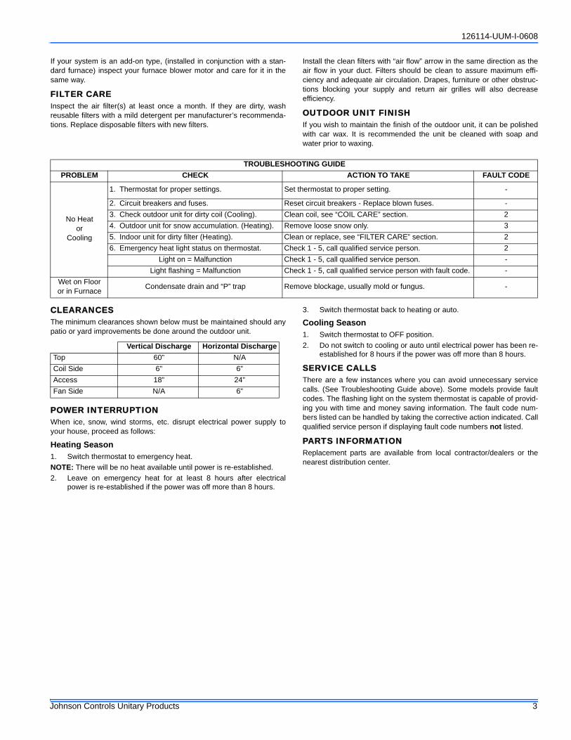
CLEARANCESThe minimum clearances shown below must be maintained should anypatio or yard improvements be done around the outdoor unit.
POWER INTERRUPTIONWhen ice, snow, wind storms, etc. disrupt electrical power supply toyour house, proceed as follows:
Heating Season1. Switch thermostat to emergency heat.NOTE: There will be no heat available until power is re-established.2. Leave on emergency heat for at least 8 hours after electrical
power is re-established if the power was off more than 8 hours.
3. Switch thermostat back to heating or auto.
Cooling Season1. Switch thermostat to OFF position.2. Do not switch to cooling or auto until electrical power has been re-
established for 8 hours if the power was off more than 8 hours.
SERVICE CALLSThere are a few instances where you can avoid unnecessary servicecalls. (See Troubleshooting Guide above). Some models provide faultcodes. The flashing light on the system thermostat is capable of provid-ing you with time and money saving information. The fault code num-bers listed can be handled by taking the corrective action indicated. Callqualified service person if displaying fault code numbers not listed.
PARTS INFORMATIONReplacement parts are available from local contractor/dealers or thenearest distribution center.
TROUBLESHOOTING GUIDEPROBLEM CHECK ACTION TO TAKE FAULT CODE
No Heator
Cooling
1. Thermostat for proper settings. Set thermostat to proper setting. -
2. Circuit breakers and fuses. Reset circuit breakers - Replace blown fuses. -3. Check outdoor unit for dirty coil (Cooling). Clean coil, see “COIL CARE” section. 24. Outdoor unit for snow accumulation. (Heating). Remove loose snow only. 35. Indoor unit for dirty filter (Heating). Clean or replace, see “FILTER CARE” section. 26. Emergency heat light status on thermostat. Check 1 - 5, call qualified service person. 2
Light on = Malfunction Check 1 - 5, call qualified service person. -Light flashing = Malfunction Check 1 - 5, call qualified service person with fault code. -
Wet on Floor or in Furnace Condensate drain and “P” trap Remove blockage, usually mold or fungus. -
Vertical Discharge Horizontal DischargeTop 60” N/ACoil Side 6” 6”Access 18” 24”Fan Side N/A 6”
Chas Roberts Air Conditioning is proud to be a family owned and operated business, serving Arizona since 1942.
As your HVAC system Installer, we can provide you with services to meet all of your Heating and Air Conditioning needs after you have taken possession of your new home:
• Sales• Service & Repair• Extended Warranties• Preventative Maintenance
We are available to speak with you Monday-Friday 7am to 8pm, Saturday 7am to 5pm, and Sunday 9am to 4pm with extended hours during the summer.
Please call, or visit our website, with all of your HVAC questions or concerns.
Limited WarrantyUPG warrants this product to be free from defects in factory workmanship and material under normal use and service and will, at its option, repair or replaceany parts that prove to have such defects according to the terms outlined on this warranty. This warranty covers only the equipment described by the ProductModel Number and Serial Number listed on the Warranty Registration Card.For your benefit and protection, return the Warranty Registration Card to UPG promptly after installation. This will initiate the warranty period and allow us tocontact you, should it become necessary. In the absence of a recorded Warranty Registration Card, the warranty period will begin upon product shipment fromUPG.This warranty extends only to the original consumer purchaser and is non-transferable. For this warranty to apply, the product must be installed according toUPG recommendations and specifications, and in accordance with all local, state, and national codes; and the product must not be removed from its place oforiginal installation. The warranty period for repair or replacement parts provided hereunder shall not extend beyond the warranty period stated below.
UPG strongly recommends regular periodic preventative maintenance on this equipment. The person most familiar with the equipment in your HVAC system isa UPG dealer. The UPG dealer can ensure your maintenance program meets the conditions of the "UPG Warranty", maximize the efficiency of the equipment,and service your unit within the mandated guidelines with regard to unlawful discharge of refrigerants into the atmosphere.This warranty applies only to products installed in the United States and Canada.
EXCLUSIONSThis warranty does not cover any:1. Shipping, labor, or material charges.2. Damages resulting from transportation, installation, or servicing.3. Damages resulting from accident, abuse, fire, flood, alteration, or acts of God (tampering, altering, defacing or removing the product serial number will
serve to void this warranty).4. Damages resulting from use of the product in a corrosive atmosphere.5. Damages resulting from inadequacy or interruption of electrical service or fuel supply, improper voltage conditions, blown fuses, or other like damages.6. Cleaning or replacement of filters.7. Damages resulting from failure to properly and regularly clean air and/or water side of condenser and evaporator.8. Damages resulting from: (I) freezing of condenser water or condensate; (II) inadequate or interrupted water supply; (III) use of corrosive water; (IV) fouling
or restriction of the water circuit by foreign material or like causes.9. Damages resulting from operation with inadequate supply of air or water.10. Damages resulting from use of components or accessories not approved by UPG (vent dampers, etc.).11. Increase in fuel or electric cost.
THIS WARRANTY IS IN LIEU OF ALL OTHER WARRANTIES, EXPRESSED OR IMPLIED, INCLUDING THE IMPLIED WARRANTIES OF MERCHANTABIL-ITY AND FITNESS FOR A PARTICULAR PURPOSE.SOME STATES DO NOT ALLOW THE DISCLAIMER OF IMPLIED WARRANTY, SO THAT THE ABOVE DISCLAIMER MAY NOT APPLY TO YOU.SOME STATES ALLOW ONLY A PARTIAL LIMITATION ON IMPLIED WARRANTIES TO LIMIT THE DURATION OF IMPLIED WARRANTIES TO THE DURA-TION OF THE EXPRESS WARRANTY. IN SUCH STATES, THE DURATION OF IMPLIED WARRANTIES IS HEREBY EXPRESSLY LIMITED TO THE DURA-TION OF THE EXPRESS WARRANTY ON THE FACE HEREOF.IN NO EVENT, WHETHER AS A RESULT OF BREACH OF WARRANTY OR CONTRACT, TORT (INCLUDING NEGLIGENCE) STRICT LIABILITY OR OTH-ERWISE, SHALL UPG BE LIABLE FOR SPECIAL, INCIDENTAL, OR CONSEQUENTIAL DAMAGES, INCLUDING BUT NOT LIMITED TO LOSS OF USE OFTHE EQUIPMENT OR ASSOCIATED EQUIPMENT, LOST REVENUES OR PROFITS, COST OF SUBSTITUTE EQUIPMENT OR COST OF FUEL OR ELEC-TRICITY. THE ABOVE LIMITATIONS SHALL INURE TO THE BENEFIT OF UPG'S SUPPLIERS AND SUBCONTRACTORS. THE ABOVE LIMITATION ONCONSEQUENTIAL DAMAGES SHALL NOT APPLY TO INJURIES TO PERSONS IN THE CASE OF CONSUMER GOODS.SOME STATES DO NOT ALLOW THE EXCLUSION OR LIMITATION OF LIABILITY FOR CONSEQUENTIAL OR INCIDENTAL DAMAGES, OR FOR STRICTLIABILITY IN TORT, SO THAT THE ABOVE EXCLUSIONS AND LIMITATIONS MAY NOT APPLY TO YOU.UPG DOES NOT ASSUME, OR AUTHORIZE ANY OTHER PERSON TO ASSUME FOR UPG, ANY OTHER LIABILITY FOR THE SALE OF THIS PRODUCT.THIS WARRANTY GIVES YOU SPECIFIC LEGAL RIGHTS. YOU MAY ALSO HAVE OTHER RIGHTS WHICH VARY FROM STATE TO STATE.For Owner's Information:
CONDENSING UNITS1
1. All 3 phase condensing units have 5-year compressor and 1-year parts (Model Numbers with 25/46 or T/W voltage codes).
PRODUCT MODEL. NO. ____________________ INSTALLATION DATE ______________________________UNIT SERIAL NO. _________________________ INSTALLING DEALER ______________________________
268895-UUM-A-0407
USER’S INFORMATION,MAINTENANCE AND SERVICE MANUALHIGH EFFICIENCYTUBULAR HEAT EXCHANGER SERIESMODELS: GY8S*DH / GM8S*DH / LY8S*DH / LM8S*DH(Single Stage Downflow/Horizontal / Standard & Low NOx)
EFFICIENCYRATINGCERTIFIED
ISO 9001Certified Quality
Management System
The manufacturer recommends that the user read all sections of thismanual and keep the manual for future reference.
SECTION I: USER’S INFORMATIONSAFETY1. The furnace area must be kept clear and free of combustible mate-
rials, gasoline and other flammable vapors and liquids.2. Insulating materials may be combustible. The furnace must be
kept free and clear of insulating materials. The furnace area mustbe examined when installed in an attic or other insulated space orwhen insulation is added to be sure that the insulation material hasbeen kept away from the furnace.
3. The furnace needs air for combustion in order to operate properlyand safely. Do not block or obstruct air openings on the furnace,air openings to the area where the furnace is installed, or spacesaround the furnace.
4. Follow the instructions exactly as shown on the OPERATINGINSTRUCTION LABEL or the Start-up and Shutdown Instructionson Page 3 of this manual when lighting the furnace or turning thefurnace off.
5. Should the gas supply fail to shut off or if overheating occurs, shutoff the gas valve to the furnace before shutting off the electricalsupply.
6. Do not use this furnace if any part has been under water. A flood-damaged furnace is extremely dangerous. Attempts to use the fur-nace can result in fire or explosion. A qualified service agencyshould be contacted to inspect the furnace and replace all gascontrols, control system parts, electrical parts that have been wetor the furnace if deemed necessary.
FIRE OR EXPLOSION HAZARD - Failure to follow safetywarnings exactly could result in serious injury, death, or prop-erty damage.— Do not store or use gasoline or other flammable
vapors and liquids in the vicinity of this or any otherappliance.
— WHAT TO DO IF YOU SMELL GAS:• Do not try to light any appliance.• Do not touch any electrical switch; do not use any phone
(including cell phone) in your building.• Leave the building immediately.• Immediately call your gas supplier from a neighbor’s
phone. Follow the gas supplier’s instructions.• If you cannot reach your gas supplier, call the fire depart-
ment.— Installation and service must be performed by a quali-
fied installer, service agency or the gas supplier.
CONTACT INFORMATION• Go to website at www.york.com click on “contact”, then click on “contact form” and follow the instructions.• Contact us by mail:
7. NEVER . . .Store flammable materials of any kind near your fur-nace. Gasoline, solvents, and other volatile liquids should bestored only in approved containers outside your home. Thesematerials vaporize easily and are extremely dangerous.
8. NEVER . . .Store cleaning materials near your furnace. Materialssuch as bleaches, detergents, powdered cleansers, etc., cancause corrosion of the heat exchangers.
9. NEVER . . . Use the area around your furnace as a storage areafor items which could block the normal flow of air. This flow of air isrequired for ventilation of the various furnace components.
INSTRUCTIONS FOR EXAMINING THE FURNACE INSTALLATIONIt is the owner’s responsibility to ensure that an annual inspection of theentire heating portion of the unit is made by a qualified service agency.Examine the furnace as outlined below in steps “1 - 6” before eachheating season. Use Figure 3 for visual reference.1. Examine the heat exchanger, vent pipe, combustion air passes-
ges, vent connectors and chimney to be sure they are clear andfree of obstructions.
2. Examine the vent pipe making sure it is firmly in place, that itslopes slightly upward and is physically sound without holes andall of the connections are secure.
3. Examine the return-air duct connections to make sure they arephysically sound, sealed to the furnace casing, and the ducts ter-minate outside the space containing the furnace.
4. Examine the furnace casing making sure the physical support issound without sagging, cracks or gaps. Examine the furnace basemaking sure it is physically sound without cracks, gaps or saggingand has a good seal.
5. Examine the furnace casing for obvious signs of deterioration.6. Examine the burner flames to make sure they are in good adjust-
ment. Refer to the pictorial sketch shown in Figure 2 as a compari-son to the actual flame.
FIGURE 1: Component Locations
FIRE OR EXPLOSION HAZARDThis furnace is designed and approved for use with Nat-ural Gas and (LP) Propane Gas ONLY. DO NOT BURNANY LIQUID FUEL OR SOLID FUEL IN THIS FURNACE.Burning any unapproved fuel will result in damage to thefurnace heat exchanger, which could result in Fire, Per-sonal Injury, and/or Property Damage.
VENT PIPE
PRESUURESWITCH
SILICONETUBE
GAS VALVE
FLAMESENSOR
INDUCED DRAFTASSEMBLY
INDUCED DRAFTMOTOR
LIMITSWITCH
IGNITOR
MANIFOLDPIPE
SAFETY SHUTOFFSWITCH
CONTROLBOARD
FLUECOLLAR
ELECTRICALJUNCTION BOX
FIGURE 2: Burner Flame Drawing
BLUE CONE PORTION OF FLAME SHOULDENTER HEAT EXCHANGER TUBE
5 EXAMINE ENTIREFURNACE CASINGSHOWN IN ALLDRAWINGS
3
4 EXAMINEFURNACECASING
EXAMINERETURN AIRDUCTCONNECTION
3
1
REMOVEPANELTO EXAMINEBURNERFLAMES
6
EXAMINE EXTERNALVENT PIPE
268895-UUM-A-0407
Unitary Products Group 3
HOW YOUR GAS FURNACE WORKSYour furnace is a very easy appliance to take for granted. Season afterseason, it sits there in your home, keeping you warm and comfortable.For this reason, you may never have given much thought to the wayyour furnace operates. In order to get the safest and most efficient oper-ation from your furnace, you should understand how your furnace doesits job.When you set your thermostat to provide more heat in your home, youare starting the heating cycle of the furnace. First, the inducer motorstarts to purge the heat exchanger of any remaining gases. Next, thehot surface ignitor glows and after a warm-up period the gas valveopens and ignition occurs. A short time later, the blower starts and dis-tributes the warm air throughout the home. When the temperature set-ting on your thermostat is reached, the gas valve closes, the mainburners are turned off, and the blower continues to run until the remain-ing warm air in the system is distributed. When the blower stops, theheating cycle has ended.
START-UP AND SHUTDOWN INSTRUCTIONSRead the Instructions Below Before Trying to Start the Furnace
A. This appliance does not have a pilot. It is equipped with an ignitiondevice which automatically lights the burner. Do not try to light theburner by hand.
B. BEFORE OPERATING; smell all around the appliance area forgas. Be sure to smell next to the floor because some gas isheavier than air and will settle on the floor.
C. Use only your hand to push the gas control switch to the “on” posi-tion. Never use tools. If the switch will not operate by hand, don’ttry to repair it, call a qualified service technician. Force orattempted repair may result in a fire or explosion.
D. Do not use this appliance if any part has been under water. Imme-diately call a qualified service technician to inspect the applianceand to replace any part of the control system and any gas control,which has been under water.
Operating Instructions:1. STOP! Read the safety information above.2. Set the thermostat to the lowest setting.3. Turn off all electric power to the appliance.4. Remove furnace door.5. Move gas control switch to the “OFF” position. Do not force. See
Figure 4.6. Wait five (5) minutes to clear out any gas. If you then smell gas,
STOP! Follow “B” in the safety information above. If you don’tsmell gas, go to next step.
7. Move gas control switch to the “ON” position. Do not force. SeeFigure 4.
8. Replace burner access panel.9. Turn on all electric power to the appliance.10. Set thermostat to the desired setting. Burner will light, which may
take 30-60 seconds.11. After three (3) trials for ignition, if the appliance will not operate fol-
low the instructions, “TO TURN OFF THE APPLIANCE” and callyour service technician or gas supplier.
To Turn Off the Appliance:1. Set the thermostat to lowest setting.2. Turn off all electric power to the appliance if service is to be per-
formed.3. Remove burner access panel.4. Move gas control switch to the “OFF” position. See Figure 4.5. Replace burner access panel.
NOTE: The spring-loaded safety cut-off switch, mounted under theblower deck will automatically cut off the electrical power supply to thefurnace when the blower panel is removed. As a safety precaution, allelectrical power and the gas supply to the furnace should be turned offbefore servicing.
FURNACE USER MAINTENANCE
If you do not follow these instructions exactly, a fire orexplosion may result causing property damage, personalinjury, and/or loss of life.
Should overheating occur, or the gas valve fail to shut off,turn the external manual gas valve in the gas supply line tothe furnace to the “off” position and let the furnace cool offbefore shutting off the electrical power supply. Refer toFigure 5.
FIGURE 4: Gas Valve - White Rodgers
FIGURE 5: Gas Piping
Before proceeding, be sure the area is well ventilated. Turnthe thermostat OFF. If the blower is running, wait until itstops automatically. Turn OFF the gas and electrical powersupplies to the furnace. Check all metal parts and surfacesto be sure they have cooled to room temperature beforeyou begin.
INLET
WRENCHBOSS
INLETPRESSUREPORT
ON
OFF
ON/OFF SWITCH(Shown in ON position)
MAIN REGULATORADJUSTMENT
OUTLET
OUTLETPRESSUREPORT
VENT PORT
EXTERNAL MANUALSHUTOFF VALVE
TO GASSUPPLY
TO GASSUPPLY
GROUNDED JOINT UNIONMAY BE INSTALLEDINSIDE OR OUTSIDE UNIT.
DRIPLEG
268895-UUM-A-0407
4 Unitary Products Group
Every time the filters are changed the following items should be visuallyinspected:
• Check combustion air and vent pipe for blockage or leakage.• Check all components to be sure they are in good condition and
that there are no obvious signs of deterioration.• Check the drain lines to make sure there are no cracks or leaks.• Check for dirt or lint on any surfaces or on components. Do not try
to clean any of the surfaces or components. Cleaning of the fur-nace and its components must be done by a qualified service pro-fessional.
If during the inspection of your furnace, you find any of the followingconditions:
• Excessive amounts of dust and lint on components.• Damaged or deteriorated components or surfaces.• Leaks or blockage in the vent pipe passages.• Water on any surface inside or outside of the furnace.
Do not operate the furnace, call a certified dealer / servicing contractorto check and / or clean your furnace, or for more information if you havequestions about the operation of your furnace.If all components appear to be in good operating condition, replace thefront panels. Turn ON the gas and electrical power supplies to the fur-nace, and set thermostat to the desired temperature.
Air FiltersDirty filters greatly restrict the flow of air and may cause damage to themoving parts of the furnace. If the filters become clogged the heatexchangers and blower motor could overheat resulting in a potentiallydangerous situation. The filters should be checked every 3 months. Onnew construction, check the filters every week for the first four weeksand every three weeks after that, especially if the indoor fan is runningcontinuously. When replacing the filter(s) you must use filters that arethe same size as those recommended in Table 1 to be sure you installthe right size filter for your furnace. Never operate your furnace withouta suitable air filter.
Removing FiltersExternally Mounted Air FiltersSome installations may have the air filter in a rack attached to the cas-ing of the furnace or placed in the return air duct. You can gain accessto the filter by pulling on the door or unscrewing the retaining screw,then slide the filter(s) out of its channel. Replace throw away filter(s)with the same size new filter(s). Throw away filter(s) may be replacedwith cleanable filter(s) at this time. Cleanable filter(s) may be cleaned asdescribed in the manufacturer instructions or as described below andthen re-installed.To replace the filter after cleaning you must do the following:1. Slide filter into place.2. Snap the door on or place the door in position and tighten the
retaining screws, if provided.3. Make sure the door is secure to the end of the filter rack.
NOTES: 1. Air velocity through throwaway type filters may not exceed 300 feet per minute. All velocities over this require the use of high velocity fil-ters.
How to Clean your FilterHigh-velocity filters may be cleaned with a vacuum cleaner or washedwith a garden hose. Be sure to shake off excess water and allow filter tocompletely dry before re-installing the filter.
Blower CareEven with good filters properly in place, blower wheels and motors willbecome dust laden after long months of operation. The entire blowerassembly should be inspected annually. If the motor and wheel areheavily coated with dust, they can be brushed and cleaned with a vac-uum cleaner. If the blower cannot be properly cleaned without removingit from the furnace, then this service must be performed by a qualifiedservice agency.
Motor LubricationThe motors in these furnaces are permanently lubricated, and do notrequire periodic oiling.
SECTION II: SERVICE AND MAINTENANCE MANUALSAFETY SECTIONThe following safety rules must be followed when servicing thefurnace.
FURNACE MAINTENANCE SECTIONThe furnace should be cleaned and adjusted by a certified dealer orqualified service contractor once a year or before the start of everyheating season. The following items must be cleaned and serviced orreplaced if there are signs of deterioration.1. The vent terminal.2. The furnace vent and combustion air intake passageways. Should
it be necessary to service the vent/air intake system, the manufac-turer recommends this service be conducted by a qualified serviceagency. The operation of this appliance requires the reassemblyand resealing of the vent/air intake system.
3. The furnace burners, ignitor and flame sensor.4. The condensate collection and disposal system. If any disassem-
bly of components containing flue or vent gases is required, aqualified service agency must perform the service.
TABLE 1: Recommended Filter Sizes
Cabinet Size Top Return (in) Top Return (cm)A (2) 14 x 20 (2) 35.6 x 50.8B (2) 14 x 20 (2) 35.6 x 50.8C (2) 14 x 20 (2) 35.6 x 50.8D (2) 14 x 20 (2) 35.6 x 50.8
Make sure you DO NOT move the clip on weight on theindoor fan wheel when cleaning the wheel. This weight isused to balance the wheel. Moving the weight will causethe fan wheel to vibrate.
ELECTRIC SHOCK, FIRE OR EXPLOSION HAZARDFailure to follow safety warnings exactly could result indangerous operation, serious injury, death or propertydamage.Improper servicing could result in dangerous operation,serious injury, and death or property damage.• Before servicing, disconnect all electrical power to the fur-
nace. • When servicing controls, label all wires prior to disconnect-
ing. Reconnect wires correctly. • Verify proper operation after servicing.
Label all wires prior to disconnection when servicingcontrols. Wiring errors can cause improper and danger-ous operation. Verify proper operation after servicing.
268895-UUM-A-0407
Unitary Products Group 5
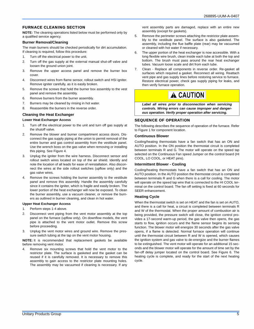
FURNACE CLEANING SECTIONNOTE: The cleaning operations listed below must be performed only bya qualified service agency.
Burner Removal/CleaningThe main burners should be checked periodically for dirt accumulation.If cleaning is required, follow this procedure:1. Turn off the electrical power to the unit.2. Turn off the gas supply at the external manual shut-off valve and
loosen the ground union joint.3. Remove the upper access panel and remove the burner box
cover.4. Disconnect wires from flame sensor, rollout switch and HSI igniter.
Remove igniter carefully, as it is easily broken.5. Remove the screws that hold the burner box assembly to the vest
panel and remove the assembly.6. Remove burners from the burner assembly.7. Burners may be cleaned by rinsing in hot water.8. Reassemble the burners in the reverse order.
Cleaning the Heat ExchangerLower Heat Exchanger Access1. Turn off the electrical power to the unit and turn off gas supply at
the shutoff valve.2. Remove the blower and burner compartment access doors. Dis-
connect the gas supply piping at the union to permit removal of theentire burner and gas control assembly from the vestibule panel.Use the wrench boss on the gas valve when removing or installingthis piping. See Figure 4.
3. Unplug the igniter from the wire harness. Disconnect sensor androllout switch wires located on top of the air shield. Identify andnote the location of all leads for ease of reinstallation. Also discon-nect the wires at the side rollout switches (upflow only) and thegas valve wires.
4. Remove the screws holding the burner assembly to the vestibulepanel and remove this assembly. Handle the assembly carefullysince it contains the igniter, which is fragile and easily broken. Thelower portion of the heat exchanger will now be exposed. To cleanthe burner assembly, use a vacuum cleaner, or remove the burn-ers as outlined in burner cleaning, and clean in hot water.
Upper Heat Exchanger Access1. Perform steps 1-4 above.2. Disconnect vent piping from the vent motor assembly at the top
panel on the furnace (upflow only). On downflow models, the ventpipe is attached to the vent motor outlet. Remove this screwbefore proceeding.
3. Unplug the vent motor wires and ground wire. Remove the pres-sure switch tubing at the tap on the vent motor housing.
NOTE: It is recommended that replacement gaskets be availablebefore removing vent motor.4. Remove six mounting screws that hold the vent motor to the
restrictor plate. The surface is gasketed and the gasket can bereused if it is carefully removed. It is necessary to remove thisassembly to gain access to the restrictor plate mounting holes.The assembly may be vacuumed if cleaning is necessary. If any
vent assembly parts are damaged, replace with an entire newassembly (except for gaskets).
5. Remove the perimeter screws attaching the restrictor plate assem-bly to the vestibule panel. The surface is also gasketed. Theassembly, including the flue baffle plate (rear) may be vacuumedor cleaned with hot water if necessary.
6. The upper portion of the heat exchanger is now accessible. With along flexible wire brush, clean inside each tube at both the top andbottom. The brush must pass around the rear heat exchangertubes. Vacuum loose scale and dirt from each tube.
7. Clean - Replace all components in reverse order. Re-gasket allsurfaces which required a gasket. Reconnect all wiring. Reattachvent pipe and gas supply lines before restoring service to furnace.Restore electrical power, check gas supply piping for leaks, andthen verify furnace operation.
SEQUENCE OF OPERATIONThe following describes the sequence of operation of the furnace. Referto Figure 1 for component location.
Continuous BlowerCooling/heating thermostats have a fan switch that has an ON andAUTO position. In the ON position the thermostat circuit is completedbetween terminals R and G. The motor will operate on the speed tapselected on the Continuous Fan speed Jumper on the control board (HICOOL, LO COOL, or HEAT pins).
Intermittent Blower - CoolingCooling/heating thermostats have a fan switch that has an ON andAUTO position. In the AUTO position the thermostat circuit is completedbetween terminals R and G when there is a call for cooling. The motorwill operate on the speed tap wire that is connected to the HI COOL ter-minal on the control board. The fan off setting is fixed at 60 seconds forSEER enhancement.
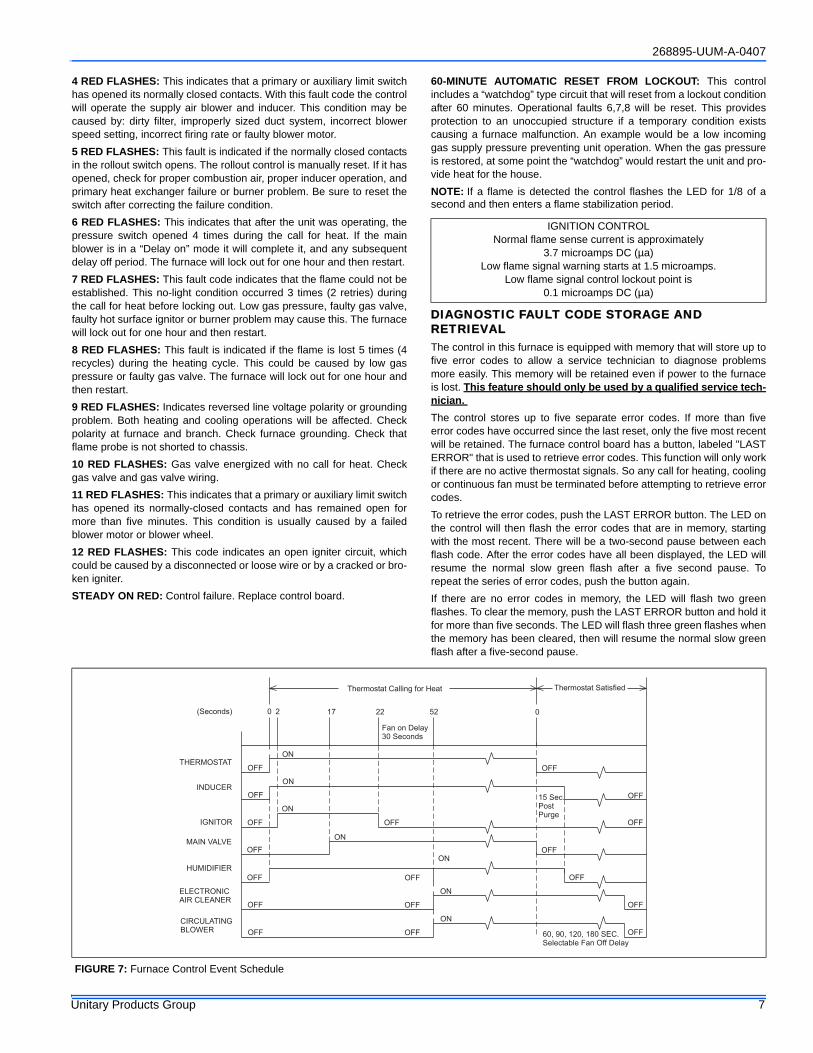
Heating CycleWhen the thermostat switch is set on HEAT and the fan is set on AUTO,and there is a call for heat, a circuit is completed between terminals Rand W of the thermostat. When the proper amount of combustion air isbeing provided, the pressure switch will close, the ignition control pro-vides a 17-second warm-up period, the gas valve then opens, the gasstarts to flow, ignition occurs and the flame sensor begins its sensingfunction. The blower motor will energize 30 seconds after the gas valveopens, if a flame is detected. Normal furnace operation will continueuntil the thermostat circuit between R and W is opened, which causesthe ignition system and gas valve to de-energize and the burner flamesto be extinguished. The vent motor will operate for an additional 15 sec-onds and the blower motor will operate for the amount of time set by thefan-off delay jumper located on the control board. See Figure 6. Theheating cycle is complete, and ready for the start of the next heatingcycle.
Label all wires prior to disconnection when servicingcontrols. Wiring errors can cause improper and danger-ous operation. Verify proper operation after servicing.
268895-UUM-A-0407
6 Unitary Products Group
If the flame is not detected within 7 seconds of the gas valve opening,the gas valve is shut off and a retry operation begins. If the flame is lostfor 2 seconds during the 10-second stabilization period, the gas valve isshut off and a retry operation begins. During a retry operation, the ventmotor starts a 15 second inter-purge and the ignitor warm-up time isextended to 27 seconds. If the flame is established for more than 10seconds after ignition during a retry, the control will clear the ignitionattempt (retry) counter. If three retries occur during a call for heat, thefurnace will shut down for one hour. If at the end of the one hour shutdown there is a call for heat, the furnace will initiate a normal start cycle.If the problem has not been corrected the furnace will again lockoutafter three retries.A momentary loss of gas supply, flame blowout, or a faulty flame probecircuit will result in a disruption in the flame and be sensed within 1.0seconds. The gas valve will de-energize and the control will begin arecycle operation. A normal ignition sequence will begin after a 15 sec-ond inter-purge. If during the five recycles the gas supply does notreturn, or the fault condition is not corrected the ignition control will lock-out for 60 minutes.During burner operation, a momentary loss of power for 50 millisecondsor longer will de-energize the gas valve. When the power is restored,the gas valve will remain de-energized and the ignition sequence willimmediately restart.
Hot Surface Ignition System
TROUBLESHOOTINGThe following visual checks should be made before troubleshooting:1. Check to see that the power to the furnace and the ignition control
module is ON.2. The manual shut-off valves in the gas line to the furnace must be
open.3. Make sure all wiring connections are secure.4. Review the sequence of operation. Start the system by setting the
thermostat above the room temperature. Observe the system’sresponse. Then use the troubleshooting section in this manual tocheck the system’s operation.
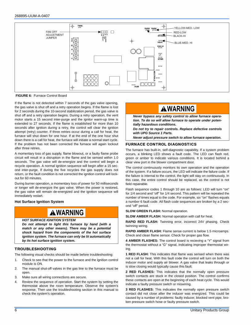
FURNACE CONTROL DIAGNOSTICSThe furnace has built-in, self-diagnostic capability. If a system problemoccurs, a blinking LED shows a fault code. The LED can flash red,green or amber to indicate various conditions. It is located behind aclear view port in the blower compartment door.The control continuously monitors its own operation and the operationof the system. If a failure occurs, the LED will indicate the failure code. Ifthe failure is internal to the control, the light will stay on continuously. Inthis case, the entire control should be replaced, as the control is notfield repairable.Flash sequence codes 1 through 10 are as follows: LED will turn “on”for 1/4 second and “off” for 1/4 second. This pattern will be repeated thenumber of times equal to the code. For example, six “on” flashes equalsa number 6 fault code. All flash code sequences are broken by a 2 sec-ond “off” period.SLOW GREEN FLASH: Normal operation.SLOW AMBER FLASH: Normal operation with call for heat.RAPID RED FLASH: Twinning error, incorrect 24V phasing. Checktwinning wiring.RAPID AMBER FLASH: Flame sense current is below 1.5 microamps.Check and clean flame sensor. Check for proper gas flow.4 AMBER FLASHES: The control board is recieving a “Y” signal fromthe thermostat without a “G” signal, indicating improper thermostat wir-ing.1 RED FLASH: This indicates that flame was sensed when there wasnot a call for heat. With this fault code the control will turn on both theinducer motor and supply air blower. A gas valve that leaks through oris slow closing would typically cause this fault.2 RED FLASHES: This indicates that the normally open pressureswitch contacts are stuck in the closed position. The control confirmsthese contacts are open at the beginning of each heat cycle. This wouldindicate a faulty pressure switch or miswiring.3 RED FLASHES: This indicates the normally open pressure switchcontact did not close after the inducer was energized. This could becaused by a number of problems: faulty inducer, blocked vent pipe, bro-ken pressure switch hose or faulty pressure switch.
FIGURE 6: Furnace Control Board
PARK PARK
HI COOL
HEAT
EAC-H
L1
XFMR
NE
UT
RA
LS
HUM
TWIN
60
90
120
180
BL
OW
ER
OF
F
DE
LA
Y
Y/Y
2W
RG
C
FAN OFFADJUSTMENTJUMPER
RED-LOW
YELLOW-MED. LOW
BLACK-HI
BLUE-MED. HI
HOT SURFACE IGNITION SYSTEMDo not attempt to light this furnace by hand (with amatch or any other means). There may be a potentialshock hazard from the components of the hot surfaceignition system. The furnace can only be lit automaticallyby its hot surface ignition system.
Never bypass any safety control to allow furnace opera-tion. To do so will allow furnace to operate under poten-tially hazardous conditions.Do not try to repair controls. Replace defective controlswith UPG Source 1 Parts.Never adjust pressure switch to allow furnace operation.
268895-UUM-A-0407
Unitary Products Group 7
4 RED FLASHES: This indicates that a primary or auxiliary limit switchhas opened its normally closed contacts. With this fault code the controlwill operate the supply air blower and inducer. This condition may becaused by: dirty filter, improperly sized duct system, incorrect blowerspeed setting, incorrect firing rate or faulty blower motor.5 RED FLASHES: This fault is indicated if the normally closed contactsin the rollout switch opens. The rollout control is manually reset. If it hasopened, check for proper combustion air, proper inducer operation, andprimary heat exchanger failure or burner problem. Be sure to reset theswitch after correcting the failure condition.6 RED FLASHES: This indicates that after the unit was operating, thepressure switch opened 4 times during the call for heat. If the mainblower is in a “Delay on” mode it will complete it, and any subsequentdelay off period. The furnace will lock out for one hour and then restart.7 RED FLASHES: This fault code indicates that the flame could not beestablished. This no-light condition occurred 3 times (2 retries) duringthe call for heat before locking out. Low gas pressure, faulty gas valve,faulty hot surface ignitor or burner problem may cause this. The furnacewill lock out for one hour and then restart.8 RED FLASHES: This fault is indicated if the flame is lost 5 times (4recycles) during the heating cycle. This could be caused by low gaspressure or faulty gas valve. The furnace will lock out for one hour andthen restart.9 RED FLASHES: Indicates reversed line voltage polarity or groundingproblem. Both heating and cooling operations will be affected. Checkpolarity at furnace and branch. Check furnace grounding. Check thatflame probe is not shorted to chassis.10 RED FLASHES: Gas valve energized with no call for heat. Checkgas valve and gas valve wiring.11 RED FLASHES: This indicates that a primary or auxiliary limit switchhas opened its normally-closed contacts and has remained open formore than five minutes. This condition is usually caused by a failedblower motor or blower wheel.12 RED FLASHES: This code indicates an open igniter circuit, whichcould be caused by a disconnected or loose wire or by a cracked or bro-ken igniter.STEADY ON RED: Control failure. Replace control board.
60-MINUTE AUTOMATIC RESET FROM LOCKOUT: This controlincludes a “watchdog” type circuit that will reset from a lockout conditionafter 60 minutes. Operational faults 6,7,8 will be reset. This providesprotection to an unoccupied structure if a temporary condition existscausing a furnace malfunction. An example would be a low incominggas supply pressure preventing unit operation. When the gas pressureis restored, at some point the “watchdog” would restart the unit and pro-vide heat for the house.NOTE: If a flame is detected the control flashes the LED for 1/8 of asecond and then enters a flame stabilization period.
DIAGNOSTIC FAULT CODE STORAGE AND RETRIEVALThe control in this furnace is equipped with memory that will store up tofive error codes to allow a service technician to diagnose problemsmore easily. This memory will be retained even if power to the furnaceis lost. This feature should only be used by a qualified service tech-nician. The control stores up to five separate error codes. If more than fiveerror codes have occurred since the last reset, only the five most recentwill be retained. The furnace control board has a button, labeled "LASTERROR" that is used to retrieve error codes. This function will only workif there are no active thermostat signals. So any call for heating, coolingor continuous fan must be terminated before attempting to retrieve errorcodes. To retrieve the error codes, push the LAST ERROR button. The LED onthe control will then flash the error codes that are in memory, startingwith the most recent. There will be a two-second pause between eachflash code. After the error codes have all been displayed, the LED willresume the normal slow green flash after a five second pause. Torepeat the series of error codes, push the button again.If there are no error codes in memory, the LED will flash two greenflashes. To clear the memory, push the LAST ERROR button and hold itfor more than five seconds. The LED will flash three green flashes whenthe memory has been cleared, then will resume the normal slow greenflash after a five-second pause.
IGNITION CONTROLNormal flame sense current is approximately
3.7 microamps DC (µa)Low flame signal warning starts at 1.5 microamps.
Low flame signal control lockout point is0.1 microamps DC (µa)
REPLACEMENT PART CONTACT INFORMATIONThis is a generic parts list. To request a complete parts list, refer to the contact information below:
• Visit our website at www.source1parts.com for the following information:1. Search for a part or browse the catalog.2. Find a dealer or distributor.3. Customer Service contact information.
a. Click on the “Brand Links” button
b. Click on the “Customer Service” button• You can contact us by mail. Just send a written request to:
York InternationalConsumer Relations
5005 York DriveNorman, OK 73069
268895-UUM-A-0407
Unitary Products Group 11
SECTION IV: WIRING DIAGRAM
FIGURE 8: Wiring Diagram
*268834*
Chas Roberts Air Conditioning is proud to be a family owned and operated business, serving Arizona since 1942.
As your HVAC system Installer, we can provide you with services to meet all of your Heating and Air Conditioning needs after you have taken possession of your new home:
• Sales• Service & Repair• Extended Warranties• Preventative Maintenance
We are available to speak with you Monday-Friday 7am to 8pm, Saturday 7am to 5pm, and Sunday 9am to 4pm with extended hours during the summer.
Please call, or visit our website, with all of your HVAC questions or concerns.
Unitary 5005 NormanProducts York OKGroup Drive 73069
Limited WarrantyUPG warrants this product to be free from defects in factory workmanship and material under normal use and service and will, at its option, repair or replaceany parts that prove to have such defects according to the terms outlined on this warranty. This warranty covers only the equipment described by the ProductModel Number and Serial Number listed on the Warranty Registration Card.UPG warrants the primary heat exchangers in the product to be free from defects in factory workmanship and material under normal use and service and will atits option, repair or furnish a replacement heat exchanger, either new or reconditioned, that meets the intended fit, use and function of the original heatexchanger for any heat exchanger furnished by UPG which proves to have such defects within the duration of warranty coverage. Alternatively, UPG may, at itsoption, extend a replacement allowance to be applied toward the purchase of a new furnace or packaged unit marketed by UPG. The exact amount of theallowance will be determined at the discretion of UPG, based upon current market conditions, but in no case shall this allowance exceed thirty (30) percent ofthe original consumer purchase price of the furnace, excluding such items as ductwork, wiring, piping and installation costs. UPG shall have no responsibilityhereunder for installation, shipping, handling or other charges except as specifically provided herein.For your benefit and protection, return the Warranty Registration Card to UPG promptly after installation. This will initiate the warranty period and allow us tocontact you, should it become necessary. In the absence of a recorded Warranty Registration Card, the warranty period will begin upon product shipment fromUPG.This warranty extends only to the original consumer purchaser and is non-transferable. For this warranty to apply, the product must be installed according toUPG recommendations and specifications, and in accordance with all local, state, and national codes; and the product must not be removed from its place oforiginal installation. The warranty period for repair or replacement parts provided hereunder shall not extend beyond the warranty period stated on this war-ranty.
UPG strongly recommends regular periodic preventative maintenance on this equipment. The person most familiar with the equipment in your HVAC system isa UPG dealer. The UPG dealer can ensure your maintenance program meets the conditions of the "UPG Warranty", maximize the efficiency of the equipment,and service your unit within the mandated guidelines with regard to unlawful discharge of refrigerants into the atmosphere.This warranty applies only to products installed in the United States and Canada.
EXCLUSIONSThis warranty does not cover any:1. Shipping, labor, or material charges.2. Damages resulting from transportation, installation, or servicing.3. Damages resulting from accident, abuse, fire, flood, alteration, or acts of God (tampering, altering, defacing or removing the product serial number will
serve to void this warranty).4. Damages resulting from use of the product in a corrosive atmosphere.5. Damages resulting from inadequacy or interruption of electrical service or fuel supply, improper voltage conditions, blown fuses, or other like damages.6. Cleaning or replacement of filters.7. Damages resulting from failure to properly and regularly clean air and/or water side of condenser and evaporator.8. Damages resulting from: (I) freezing of condenser water or condensate; (II) inadequate or interrupted water supply; (III) use of corrosive water; (IV) fouling
or restriction of the water circuit by foreign material or like causes.9. Damages resulting from operation with inadequate supply of air or water.10. Damages resulting from use of components or accessories not approved by UPG (vent dampers, etc.).11. Increase in fuel or electric cost.THIS WARRANTY IS IN LIEU OF ALL OTHER WARRANTIES, EXPRESSED OR IMPLIED, INCLUDING THE IMPLIED WARRANTIES OF MERCHANTABIL-ITY AND FITNESS FOR A PARTICULAR PURPOSE.SOME STATES DO NOT ALLOW THE DISCLAIMER OF IMPLIED WARRANTY, SO THAT THE ABOVE DISCLAIMER MAY NOT APPLY TO YOU.SOME STATES ALLOW ONLY A PARTIAL LIMITATION ON IMPLIED WARRANTIES TO LIMIT THE DURATION OF IMPLIED WARRANTIES TO THE DURA-TION OF THE EXPRESS WARRANTY. IN SUCH STATES, THE DURATION OF IMPLIED WARRANTIES IS HEREBY EXPRESSLY LIMITED TO THE DURA-TION OF THE EXPRESS WARRANTY ON THE FACE HEREOF.IN NO EVENT, WHETHER AS A RESULT OF BREACH OF WARRANTY OR CONTRACT, TORT (INCLUDING NEGLIGENCE) STRICT LIABILITY OR OTH-ERWISE, SHALL UPG BE LIABLE FOR SPECIAL, INCIDENTAL, OR CONSEQUENTIAL DAMAGES, INCLUDING BUT NOT LIMITED TO LOSS OF USE OFTHE EQUIPMENT OR ASSOCIATED EQUIPMENT, LOST REVENUES OR PROFITS, COST OF SUBSTITUTE EQUIPMENT OR COST OF FUEL OR ELEC-TRICITY. THE ABOVE LIMITATIONS SHALL INURE TO THE BENEFIT OF UPG'S SUPPLIERS AND SUBCONTRACTORS. THE ABOVE LIMITATION ONCONSEQUENTIAL DAMAGES SHALL NOT APPLY TO INJURIES TO PERSONS IN THE CASE OF CONSUMER GOODS.SOME STATES DO NOT ALLOW THE EXCLUSION OR LIMITATION OF LIABILITY FOR CONSEQUENTIAL OR INCIDENTAL DAMAGES, OR FOR STRICTLIABILITY IN TORT, SO THAT THE ABOVE EXCLUSIONS AND LIMITATIONS MAY NOT APPLY TO YOU.UPG DOES NOT ASSUME, OR AUTHORIZE ANY OTHER PERSON TO ASSUME FOR UPG, ANY OTHER LIABILITY FOR THE SALE OF THIS PRODUCT.THIS WARRANTY GIVES YOU SPECIFIC LEGAL RIGHTS. YOU MAY ALSO HAVE OTHER RIGHTS WHICH VARY FROM STATE TO STATE.For Owner's Information:


![1. Ps42b430p2wxxh Chas f65a[P_hd]_b430](https://static.documents.pub/doc/80x56/540cfd877bef0aff298b46c0/1-ps42b430p2wxxh-chas-f65aphdb430.jpg)


