Page 1
INSTRUCTION MANUAL INSTRUCTION MANUAL INSTRUCTION MANUAL INSTRUCTION MANUAL
MODEL:NF-816
ORIGINAL AUTHENTIC
ed produnt cte tsa ,Ping noteit arf lte lon wu eo dC
ORIGINAL AUTHENTIC
REV1.0
Your excellent helper in cable test!
Underground Wire Locator
Page 2
1.DESCRIPTION ....................................................................1
2.OPERATION .......................................................................2
A.Transmitter Connection ......................................................2
B.Locating & Tracking Buried Wires ...................................2
C.Measuring Depth .................................................................3
D.Tracking Behind Walls ......................................................3
E.Locating Circuit Breaker .....................................................4
F. Pinpointing Drill Sites ........................................................5
G.Determining Which Receptacles
are on Specific Circuits ..........................................................6
H.Locating Alarm, Sound & Computer Wires .....................6
I. External Earphone .............................................................6
J.Locating Hidden Receptacles ............................................6
K.White LED Flash Light ........................................................6
3.SPECIFICATIONS ..............................................................7
4.MAINTENANCE .................................................................8
Diagram of series products .............................................9
Your excellent helper in cable test!
Contents
Page 3
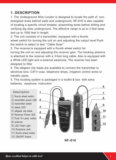
1. DESCRIPTION1. The Underground Wire Locator is designed to locate the path of non-
energized wires behind walls and underground. NF-816 is also capable
of locating a specific circuit breaker, pinpointing wires before drilling and
verifying dig sites underground. The effective range is up to 3 feet deep
and up to 1000 feet in length.
2. The unit consists of a transmitter, equipped with a thumb
wheel switch for turning the unit on and adjusting the output level Push
the switch to select to test“Cable Scan”
3. The receiver,is equipped with a thumb wheel switch for
turning the unit on and adjusting the receiver gain. The tracking antenna
is attached to the receiver with a 3-foot long cable. Also is equipped with
a White LED light and a external earphone, The receiver has been
designed to filter
4. The alligator clip leads are available to connect the transmitter to
electrical wire, CATV coax, telephone drops, irrigation control wires or
metallic pipes.
5. This locating system is packaged in a toolkit & box with extra
batteries, earphone instruction
[1]
[2]transmitter power LED
[3]transmitter switch
[4]status LED
[5]alligator clip leads
[6]Receiver Power LED
[7]Push To Lamp button
[8]antenna
[9]LED Flash Light
[10]Earphone Jack
[11]
[12]ON/OFF Switch
thumb wheel switch
thumb wheel switch
Description
NF-816
1
2
3
4
5
6
7
8
9
10
11
12NF-816
Your excellent helper in cable test! 1
Page 4
2. OPERATION
A. Transmitter Connection
To locate non-energized cable, Push transmitter switch to“Cable Scan”.
There are two options for connection. You can connect one lead of the
transmitter to the cable and the other lead to grounded earth or you can
connect one conductor with grounded earth of a non-shielded drop wire.
You can also connect two conductors to non-shielded drop wire.
B. Locating & Tracking Buried Wires
To locate buried electrical wires, CATV coax, telephone drops, irrigation
control wires or metallic pipes, Push transmitter switch to“Cable Scan”
attach one alligator clip lead of the 816T to an independent grounded
earth with a grounding stake or screwdriver. Do not connect to common
ground such as a metal water pipe or the pedestal ground as they can
cause cancellation of the reflected signal or produce false locating
signals. Theother lead is attached to the cable or metallic pipe in the
following manner:
1. Non-energized Electrical Wires: Attach alligator clip lead to wires.
2. CATV Coax: Attach lead to the shield. This aviods signal disruption.
3. Telephone Drops: Attach controller lead to sheath. This aviods signal
disruption.
4. Irrigation Controller Wires: Attach lead to common wire or station wire.
5. Gas Pipes with Pilot Wire: Attach lead to pilot wire.
6. Metallic Pipes: Attach lead to pipe.
Once the transmitter is attached to the cable, turn thumb wheel switch to
high tone. swing the receiver antenna close to the ground and approxim
-ately ten to fifteen feet away from the transmitter location. The tone will
be heard on either side of the path with a null (absence of tone) directly
over the path. Proceed along the path following the“null”. direction adjust
the transmitter and receiver controls to achieve further distances.
Your excellent helper in cable test!2
Page 5
D. Tracking Behind Walls
Hold the receiver in one hand and the antenna in the other. Position
the antenna flat along the wall and at a right angle to the wire, approxi
-mately five feet away from the transmitter. Gently sweep around the
subject area until a PEAK signal is found. Follow the PEAK signal to
track the path of the wire.
Peak signal will become
weaker as the antenna
gets further away from
the path of the wire.
Adjust the receiver
gain first, then if
necessary, also adjust
the transmitter output
for best results.
(Fig.02)
C. Measuring Depth
Once the path has been
determined, mark the ground
at a null point along the path.
Hold the receiver antenna at
a 45-degree angle to the
ground and move at a right
angle away from the path of
the wire until another null is
found. Mark this point.
The distance between the
two marks is the approximate
depth of the wire.(Fig.01)
Fig·01-Measuring Depth
Receiver
Antenna
NullPoints 45
。
Ground LevelCable or Pipe
Fade
Peak
±5 Feet
Fade
NF-816
Your excellent helper in cable test! 3
Page 6
E. Locating Circuit Breakers (Light Commercial & Residential Applications)
To locate the circuit breaker for a specific outlet, the hookup procedure
is the same Proceed to the breaker box and remove the panel so the
wires leading into the breakers are exposed and turn the receiver on
the high tone.
NOTE: Due to varying installation techniques, the signal might be strong
on more than one wire
on the same phase and
AC interference or
computer data buzz may
be present. Scan each
breaker wire by pointing
the antenna at the wires.
The wire in question will
have a distinct NULL
(absence of tone) when
the antenna tip is on the
subject wire with tone
on either side. (Fig.03)
Check signal strength on each subject wire by sliding the antenna in and
out along each side of these wires. The loudest signal will be received
when the wire is
approximately one inch
from the tip of the
antenna. Choose the
loudest, clearest
conductor and with the
antenna still held
against the suspect
wire, turn the breaker
off. The signal will
cease, positively
identifying that
breaker.(Fig.04)
Fig·03-Locating Circuit Breakers
Tone
Null
Tone
In
Out
Fade
Loudest 1〃
Fig·04-Locating Circuit Breakers
Your excellent helper in cable test!4
Page 7
Fig·05-Idetifying The Phase
ABCABCABC
ABCABCABC
To
ne
Nu
ll
To
ne
Tone Tone
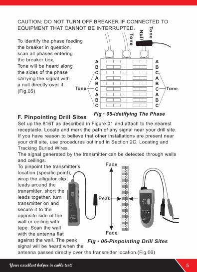
CAUTION: DO NOT TURN OFF BREAKER IF CONNECTED TO
EQUIPMENT THAT CANNOT BE INTERRUPTED.
To identify the phase feeding
the breaker in question,
scan all phases entering
the breaker box.
Tone will be heard along
the sides of the phase
carrying the signal with
a null directly over it.
(Fig.05)
Fig·06-Pinpointing Drill Sites
Fade
Fade
Peak
NF-816
Your excellent helper in cable test! 5
F. Pinpointing Drill Sites
Set up the 816T as described in and attach to the nearest
receptacle. Locate and mark the path of any signal near your drill site.
If you have reason to believe that other installations are present near
your drill site, use procedures outlined in Section 2C, Locating and
Tracking Buried Wires.
The signal generated by the transmitter can be detected through walls
and ceilings.
To pinpoint the transmitter's
location (specific point),
wrap the alligator clip
leads around the
transmitter, short the
leads together, turn
transmitter on and
secure it to the
opposite side of the
wall or ceiling with
tape. Scan the wall
with the antenna flat
against the wall. The peak
signal will be heard when the
antenna passes directly over the transmitter location.(Fig.06)
Figure 01
Page 8
G. Determining Which Receptacles are on Specific Circuits
Set up 816T as outlined in Figure 01 and radius adjacent outlets with
antenna. You will have a tone at the receptacle/outlet if it is in the
circuit. If a clear signal is not received, that outlet is not part of the
circuit you are detecting.
H. Locating Alarm, Sound & Computer Wires
To locate other wires, it is best to disconnect the wire in question and
directly attach only one transmitter lead to the subject wire, letting the
other lead hang. Trace the path as outlined in, then trace the part of
wire.
I. External Earphone
User can connect a 3.5mm earphone
to the Receiver Earphone Jack Under
noisy environment to improve the
operating efficiency.(Fig.07)
J. Locating Hidden Receptacles
To locate receptacles that have been covered up by drywall, attach one
transmitter lead to the wire at the breaker and let the other lead hang.
Scan the walls in the room with the antenna flat against the wall
following the path or peak signal. The signal will be lost or fade rapidly
once the tone get closer to the end of the wire.
K. White LED Flash Light
User can activate LED flash light
if user press the“Push To Lamp”
button.(Fig.08)
Fig·07
Fig·08
Your excellent helper in cable test!6
Page 9
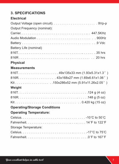
3. SPECIFICATIONS
Electrical
Output Voltage (open circuit). . . . . . . . . . . . . . . . . . . . . . . . 9Vp-p
Output Frequency (nominal):
Carrier. . . . . . . . . . . . . . . . . . . . . . . . . . . . . . . . . . . .. . 447.5KHz
Audio Modulation . . . . . . . . . . . . . . . . . . . . . . . . . . . . . . . 900Hz
Battery . . . . . . . . . . . . . . . . . . . . . . . . . . . . . . . . . . . . . . . .9 Vdc
Battery Life (nominal)
816T. . . . . . . . . . . . . . . . . . . . . . . . . . . . . . . . . . .. . . . . . . 35 hrs
816R . . . . . . . . . . . . . . . . . . . . . . . . . . . . . . . . . . . . . . . . 20 hrs
Physical
Measurements
816T. . . . . . . . . . . . . . . . . . . . . . 49x135x33 mm (1.93x5.31x1.3″)
816R. . . . . . . . . . . . . . . . . . . . 43x168x27 mm (1.69x6.61x1.06″)
Kit . . . . . . . . . . . . . . . . . . . .150x286x52 mm (5.91x11.26x2.05″)
Weight
816T. . . . . . . . . . . . . . . . . . . . . . . . . . . . . . . . . . . . . .124 g (4 oz)
816R. . . . . . . . . . . . . . . . . . . . . . . . . . . . . . . .. . . . . .148 g (5 oz)
Kit . . . . . . . . . . . . . . . . . . . . . . . . . . . . . . . . . . . 0.420 kg (15 oz)
Operating/Storage Conditions
Operating Temperature:
Celsius. . . . . . . . . . . . . . . . . . . . . . . . . . . . . . . . . . -10°C to 5 0° C
Fahrenheit. . . . . . . . . . . . . . . . . . . . . . . .. . . .. . . . . 14°F t o 1 22°F
Storage Temperature:
Celsius. . . . . . . . . . . . . . . . . . . . . . . . . . . .. . . . . . . .-17°C to 7 5°C
Fahrenheit. . . . . . . . . . . . . . . . . . . . . . . . . . . . . . . . .0°F to 1 67°F
Your excellent helper in cable test! 7
Page 10
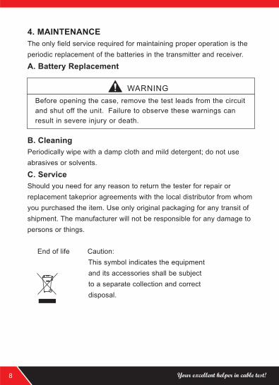
4. MAINTENANCE
The only field service required for maintaining proper operation is the
periodic replacement of the batteries in the transmitter and receiver.
A. Battery Replacement
B. Cleaning
Periodically wipe with a damp cloth and mild detergent; do not use
abrasives or solvents.
C. Service
Should you need for any reason to return the tester for repair or
replacement takeprior agreements with the local distributor from whom
you purchased the item. Use only original packaging for any transit of
shipment. The manufacturer will not be responsible for any damage to
persons or things.
End of life Caution:
This symbol indicates the equipment
and its accessories shall be subject
to a separate collection and correct
disposal.
WARNING
Before opening the case, remove the test leads from the circuit
and shut off the unit. Failure to observe these warnings can
result in severe injury or death.
Your excellent helper in cable test!8
Page 11
Your excellent helper in cable test! 9
NF-388 NF-903 NF-906A
NF-268
NF-468L NF-3468 NF8108-M
NF-801B NF-806R
NF-306 NF-868 NF-8208
Page 12
Your excellent helper in cable test!
SHENZHEN NOYAFA ELECTRONIC CO.,LTD