100


Your Partner in Safe Power Solutions
33
Red Sea Cables Company (RESCAB) was established as a closed joint stock company in 2008 in the Kingdom of Saudi Arabia with a capital of 370 million SAR. RESCAB is a member of Al-Abdullatif group of companies. The largest two shareholders in RESCAB are Al-Abdullatif Group Holding Company and Al-Abdullatif Industrial Investment Company.
RESCAB manufactures and distributes power cables and wires of all types and sizes and caters to the growing demand of the local market, as well as exports to other markets especially in neighboring countries.
RESCAB plant is located in Yanbu city in the Industrial Area of the Royal Commission of Jubail and Yanbu. The 100,000-square-meter plant is built with state-of-the-art international technologies and is based on best European know-how in the field of wire and cable production conforming to the international standards to manufacture products of highest quality.
RESCAB offers its products to various sectors like power, oil & gas, infrastructure, utilities, industries and residential sectors. The company is technically well equipped to adapt to special requirements in line with the progress in the field of wire and cable manufacturing technologies.
RESCAB has ISO: 9001:2008 certification.
RESCAB vision is to supply safe and reliable products complying with best quality standards, continually enhance product quality through efficient quality management systems and provide efficient after-sales service.
About RESCAB

4 5
Table of Contents Page No.
5 - 36
37 - 97
Part 1: Technical Information
Part 2: Product Range
4 5
Your Partner in Safe Power Solutions
Part 1: Technical Information
6 7
Technical Information and Cable Construction
VOLTAGE DESIGNATION:
3-Phase Alternating Current transmission system is mostly used all over the World. The Rated Voltage of the Cable for a given application shall be suitable for the operating conditions in the system in which the cable is used. The design or Rated Voltage of the Cables is expressed in the form Uo/U (formerly Eo/E).
The Rated Voltage Uo/U (Um) of the Cables considered in this Catalogue are 0.6 / 1 (1.2) kV and 1.8 / 3(3.6) kV .
Uo= the Rated Power frequency Voltage between conductor and earth or metallic screen for which the Cable is designed.U= the Rated Power frequency Voltage between conductors for which the Cable is designed.Um= the maximum Value of the “highest system voltage” for which the equipment may be used with reference to IEC 60038.It should be noted that in a system where an earth fault is not automatically and promptly isolated, the extra stress on the insulation of cables during the earth fault reduces the life of cable to a certain degree.
CONDUCTORS:
A conductor is a metallic current carrying component of the Cable. The conductors are in accordance with BS EN 60228. Plain Annealed soft drawn Copper conductors with Conductivity 100% IACS standard are usually used.
Aluminium Conductors are also being used due to the everyday increasing prices of Copper. The conductivity of Aluminum is 61% IACS standard.
RESCAB is using Electrolytic Copper in accordance with ASTM B-49 and Aluminium as per ASTM B-233 and producing both metal Conductors in accordance with BS EN 60228 for the manufacturing of Electric Cables.The Conductors are designated with their Nominal area, minimum number of wires and Maximum D.C Resistance in BSEN 60228. RESCAB Cables are produced with the following classes and shapes of conductors in accordance with BSEN 60228:
Class I - Round solid conductors
Class II- Round stranded or, round Compacted or Shaped Stranded conductors
Class V- Round Flexible conductors.
6 7
Your Partner in Safe Power Solutions
Technical Information and Cable Construction
INSULATION:
The Conductors are insulated by the extruded dielectric materials like Polyvinyl Chloride (PVC) and Cross Linked Polyethylene (XLPE). Following Grades of Insulation are being used in RESCAB in accordance with EN BS 50363- 3, BS 6346, BS 5467, BS 7655 and IEC 60502- 1.
TI 1 or PVC/A – it is suitable for a continuous permissible conductor temperature of 70 deg C
TI 3 – it is suitable for a continuous permissible conductor temperature of 90 deg C.
XLPE (GP8) - it is suitable for a continuous permissible conductor temperature of 90 deg C.
Special Insulation material for Hazardous area application is available with LSFOH and fire retardant thermosetting insulation. All RESCAB Insulations are subjected to online SPARK testing Application in accordance with BS EN 62230 and BS 5099.
Ultraviolet (UV) stabilized Colors for sunlight protection are used for the identification of Phase and Neutral conductors; usually the color codes Red, Yellow, Blue are used for Phase, Black for Neutral and Green/Yellow for Earth conductor. Core Identification will be provided as per customer requirements.
The color codes are given as below:
ASSEMBLY:
The individual multi cores of cables are subject to core assembly and lay up together to form a reasonable circular shape. The Interstices between the cores are filled with Non-hygroscopic Polypropylene Strings fillers wherever required. Polypropylene binder tapes are applied helically to keep the assembled cores intact and also served as a separator between the insulation and inner sheath or separation sheath as applicable.
INNER COVERING AND BEDDING:
The inner covering and bedding is an extruded layer of PVC material provided above the Multi-Core assembly. It is compatible with the insulation material. PVC bedding is applied under the Armour (Steel wire or Alum wire.etc) in accordance with IEC 60502- 1, BS 5467 and BS 6346. The application of Inner covering may be omitted in the construction of un-armoured cables and cables without collective metallic layer provided the outer shape of the cable remains practically circular and no adhesion occurs between cores and sheath.
No of CoresColor code as per
IEC 60502 - 1Color code as per
BS 5467, 6346 Latest
1 Red or Black Brown or Blue
2 Red and Black Brown and Blue
3 Red, Yellow and Blue Brown, Black and Grey
4 Red, Yellow, Blue and Black Blue, Brown, Black and Grey
5 Red, Yellow, Blue, Black and Green/ Yellow Green/ Yellow, Blue, Brown, Black and Grey

8 9
ARMOUR:
The Armouring is used usually for direct burial underground Cables. It may be used for Earthing and provides protection against mechanical damage. It consist of Aluminium wire, Aluminium tape, Galvanized Steel wire or Double Steel Tape Armour applied helically over the bedding in accordance with IEC 60502- 1, BS EN 10257, BS 5467, BS 6346. Armouring for single core Cables will be Non-Magnetic.
OUTER SHEATH:
It is also known as Outer jacket of Cable and consists of a Black Extruded layer of PVC Type ST2 or Type 9 in accordance with IEC 60502- 1, BS 5467 and BS 6346 respectively. RESCAB Cables are having PVC outer sheath Fire Retardant to IEC 60332 -1. It can resists moisture, acid and alkaline content present in normal soil.Special properties for Hazardous area or potentially explosive gas atmosphere and Fire Retardant application with minimum Oxygen Index 30 or more are available upon requirements.Anti-Termite, Anti-Rodent, LSFOH, HDPE, MDPE, etc are also available.
RECOMMENDATIONS FOR INSTALLATION:
There are various methods and measures recommended for the installation of Low Voltage Cables. Some of them are given below:
• Cables should be installed and used in association with other equipment in accordance with BS 7671, 17th Edition.• Un-armoured Cables are not recommended for direct burial application. They are usually used on cable Trays and in ducts.• Armoured Cables are usually recommended for underground and under Road crossings applications.• Care should be exercised during installation to avoid any mechanical damage or damage of Cable Coverings or outer sheath before and during the installation, recommended maximum pulling tension and pulling tooling to be used. This is important in wet or other aggressive environments. • If Cables are to be installed in ducts, the correct size of duct should be used. Reference should be made to ERA publication 69 - 30, Part III. • The cables should not be bent during installation to a radius smaller than the Minimum bending radius given below. Minimum bending radius during installation must be maintained larger wherever possible to avoid the damage of the cable.
Technical Information and Cable Construction
D: Outer diameter of cable.
•The Protective End caps should not be removed from the Cable ends until immediately prior to termination or jointing especially for Cables that do not have extruded bedding. When the end caps have been removed the unprotected ends of the cable should not be exposed to moisture.•It is to be noted that owing the absence of a metal sheath, all earth fault currents will return through the armour unless there is a parallel bonding connection to relieve them of some of the Fault current. In either event it is necessary to ensure that there is no discontinuity in the return current via armour and the resistance added by bonds and clamps is kept to a minimum.
Cable TypeArmoured/Un-armoured
Cable Min. Bending Radius
Circular Copper Conductor 6D
Shaped Copper/ Aluminium Conductor 8D

8 9
Your Partner in Safe Power Solutions
•The Cable support system should be such as to avoid damage or danger under normal or fault conditions. Bonding Clamps in joints should be electrically connected with a conducting material having conductance at least equal to that of the length of the armour it replaces, and with adequate thermal capacity to avoid excessive overheating under short circuit conditions, where excessive amount of short circuit current will flow in initial seconds. The type of jointing and filling compounds employed should be chemically compatible with the cable materials.•It is recommended that the Cables to be installed only when both the cable and ambient temperature are above 0 degree C and have been so for the previous 24 hours, or where special precautions have been taken to maintain the cable above this temperature.
1.0 GENERAL BASIS OF AMPACITY DETERMINATION:
The Electric cables suffers electrical losses during service. These losses are usually referred as Ohmic and Induced Losses and generate heat in the conductor, insulation and metallic components. The heat evolved must be transmitted to the ambient Earth or Air.
The Ampacity or Current Rating of Cable is dependent on the way this heat is transmitted to the Cable surface and then dissipated to the sourrounding. Temperature is clearly an important factor and is expressed as a conductor temperature to establish a datum for the Cable itself. A maximum conductor temperature is fixed which is commonly the limit for the insulation material, without undue ageing, for a resonable maximum life then, by choosing a base ambient temperature for the sourroundings, a permissible temperature rise is available from which a maximum cable Ampacity can be calculated for a particular environment.
Under steady state conditions the difference between the conductor temperature and the external ground or ambient temperature is related to the total heat losses and the Law of heat flow is very similar to Ohm>s Law. Heat flow corresponds to Current, Tempearture difference to voltage and the total thermal resistance in the cable and sourroundings to Electrical resistance. Using this analogy it is possible to construct a circuit diagram as illustrated in Fig.1. This shows how the heat generated at several positions has to flow through a number of layers of different thermal resistances. By measuring values for the materials, Ampacity or current Ratings calculation can then be made.
Technical Information and Cable Construction
Fig. 1: Circuit Diagram to represnt heat generated in a 3-core Metal sheathed Cable.
AMPACITY OF CABLES
10 11
Technical Information
AMPACITY OF CABLES
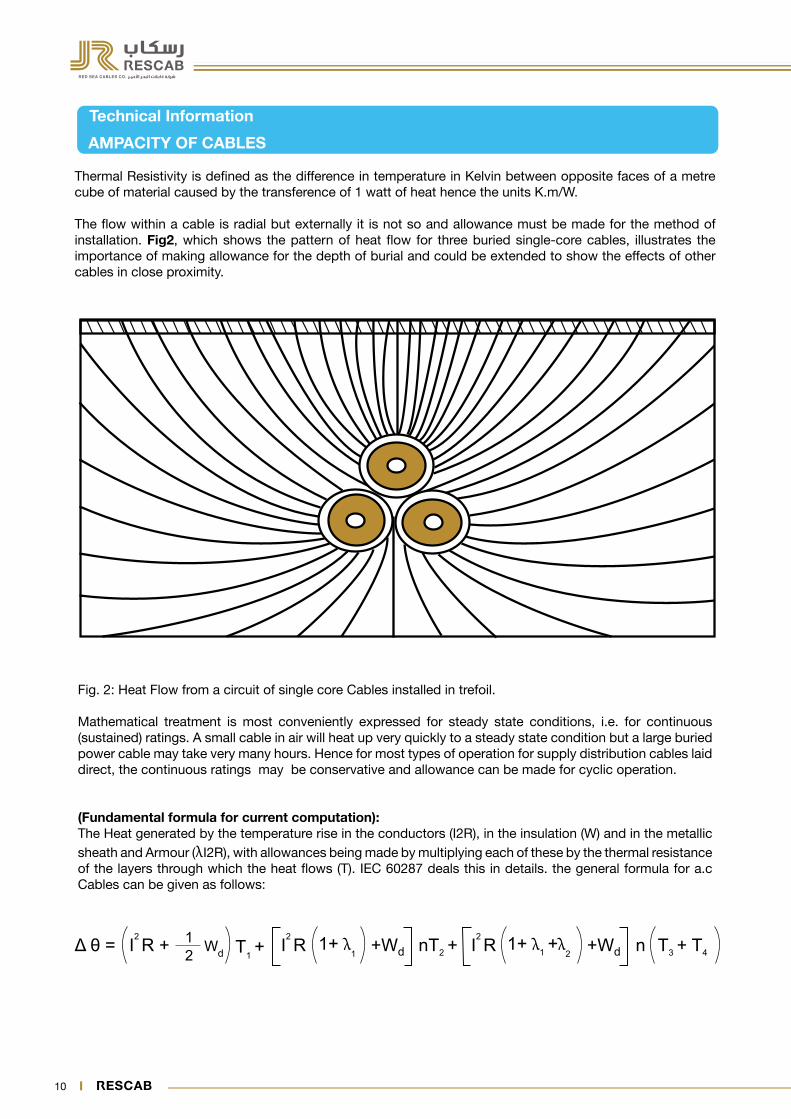
Thermal Resistivity is defined as the difference in temperature in Kelvin between opposite faces of a metre cube of material caused by the transference of 1 watt of heat hence the units K.m/W.
The flow within a cable is radial but externally it is not so and allowance must be made for the method of installation. Fig2, which shows the pattern of heat flow for three buried single-core cables, illustrates the importance of making allowance for the depth of burial and could be extended to show the effects of other cables in close proximity.
Fig. 2: Heat Flow from a circuit of single core Cables installed in trefoil.
Mathematical treatment is most conveniently expressed for steady state conditions, i.e. for continuous (sustained) ratings. A small cable in air will heat up very quickly to a steady state condition but a large buried power cable may take very many hours. Hence for most types of operation for supply distribution cables laid direct, the continuous ratings may be conservative and allowance can be made for cyclic operation.
(Fundamental formula for current computation):The Heat generated by the temperature rise in the conductors (I2R), in the insulation (W) and in the metallic sheath and Armour (λI2R), with allowances being made by multiplying each of these by the thermal resistance of the layers through which the heat flows (T). IEC 60287 deals this in details. the general formula for a.c Cables can be given as follows:

10 11
Your Partner in Safe Power Solutions
Technical Information
AMPACITY OF CABLES
Δ θ = Conductor temperature rise (K)I = Current Flowing in one conductor (A)R = Alternating resistance per unit length of the conductor at maximum operating temperature (Ω/m).Wd = Dielectric loss per unit length for the insulation surrounding the conductor (W/m).T1 = Thermal resistance per unit length between one conductor and metallic sheath (K.m/W).T2 = Thermal resistance per unit length of the bedding between sheath and armor (K.m/W).T3 = Thermal resistance per unit length of the external serving/ outer sheath of the cable (K.m/W).T4 = Thermal resistance per unit length between the cable surface and the surrounding medium (K.m/W).n = No. of load carrying conductors in the cable (conductors of equal size and carrying the same load).λ1 = Ratio of losses in the metal sheath to total losses in all conductors in that cable.λ1 = Ratio of losses in the armoring to total losses in all conductors in that cable.
The Formula may be written as follows to obtain the permissible current rating:
Please note that the above formula only provides ratings for the prescribed representative conditions. it does not allow for heat generation from any other source, such as other cables in close proximity, or from exposure to direct solar radiation. We can refer to IEC 60287 for further details in this regard.
Conisdering a 4 core-600 / 1000 Volts Power Cable, '' n '' may be assumed to be 3 if the fourth conductor is neutral or is a protective conductor. this assumes that the neutral conductor is not carrying current, which is due to the presence of Harmonics. Where Triple harmonic currents, particularly the Third Harmonic, are present in a system they do not cancel in the neutral. This means that all four conductors will be loaded and measurements have shown that the current in the neutral conductor may be higher than 50Hz current in phase currents. Therefore, the use of Power cable with reduced neutral conductor usually known as 3 1 /2 - core cable must be avoided.
Presently Electrical Engineers are using Neher - McGrath Calculating method, IEEE Stand Power Cable Ampacity Tables and IEC 60287 Group of Standard for computing the Ampacities of Electric Cables.Ampacity Tables are available in the catalogues of Cable Manufacturers are based on the same for many conductor sizes and various types of Cables. These Tables are designed to cover most common installation conditions.

12 13
Technical Information
AMPACITY OF CABLES
Cable design parameters and dimensions of cables are based on IEC 60502 -1, which may have a slight variation in practical values applied in cable manufacturing to the best common Engineering practices.
Red Sea Cables Company (RESCAB) offers our standard products having PVC Insulation TypeTI -1 ( 70 Deg.C ), Heat resistant PVC Type TI-3 ( 90 Deg.C )and Cross-linked Polyethylene XLPE (90 Deg.C ).
The basis of the standard conditions is the climatic condition of the Kingdom of Saudi Arabia, having following details:
Ambient Air Temperature: 40 °C Ambient Ground Temperature: 35 °C Depth of laying in ground: 0.50 m Soil Thermal Resistivity 1.2 K.m/W
For other Installation conditions or any value of different air/ground temperature, depth of laying, different soil thermal resistivity, the customer is advised to multiply the tabulated current rating by the de-rating factor values as in tables 1 to 5 for direct buried cables in ground and tables 7 to 10 for cables installed in ducts.
2.0 INSTALLATION CONDITIONS FOR DIRECT BURIAL CABLES
For a cable installed direct buried, the following tables will be used to calculate the current rates based on the actual soil thermal resistivity, Ground ambient temperature and the Depth of Laying.
Table 1: Rating Factors for Ground temperature variations
Ground Temperature 15°C 20°C 25°C 30°C 35°C 40°C 45°C 50°C 55°C
Cable Type
PVC Insulated 70°C 1.25 1.20 1.13 1.07 1 0.93 0.85 0.76 0.65
PVC Insulated 90°C 1.17 1.13 1.09 1.04 1 0.95 0.90 0.85 0.80
XLPE Insulated 1.16 1.13 1.09 1.03 1 0.95 0.90 0.85 0.80

12 13
Your Partner in Safe Power Solutions
Technical Information
AMPACITY OF CABLES
Table 2: Rating Factors for depth of Laying (to center of cable or trefoil group of cables)
Depth of Laying (m) upto 70 mm² 95 mm² to 240 mm² 300 mm² and bove
0.50 1.00 1.00 1.00
0.60 0.99 0.98 0.97
0.80 0.97 0.96 0.94
1.00 0.95 0.93 0.92
1.25 0.94 0.92 0.98
1.50 0.93 0.90 0.87
1.75 0.92 0.89 0.86
2.00 0.91 0.88 0.85
2.50 0.90 0.87 0.84
Table 3: Rating Factors for variations in thermal resistivity of soil (average values)
Size of Cables (mm)2
Soil Thermal Resistivity (°C m/W)
0.8 0.9 1.0 1.5 2.0 2.5 3.0
Single Core Cables
Upto 150 1.16 1.12 1.07 0.91 0.81 0.73 0.66
From 185 to 300 1.17 1.12 1.07 0.91 0.80 0.73 0.66
From 400 to 1000 1.17 1.12 1.07 0.91 0.80 0.73 0.66
Multi Core Cables
Upto 16 1.12 1.08 1.05 0.93 0.84 0.77 0.72
From 25 to 150 1.14 1.10 1.06 0.92 0.82 0.75 0.69
From 185 to 500 1.15 1.10 1.07 0.92 0.81 0.74 0.67

14 15
Technical Information
AMPACITY OF CABLES
Table 4: Group rating factors for circuits of three single core cables in trefoil or laid flat touching, in horizontal formation
Table 5: Group rating Factors for multicore cables in Horizontal formation
Num
ber
of
circ
uits
Cables Touching Cable to Cable Clearance A
Trefoil Flat Laying 0.15 m 0.30 m 0.45 m 0.60 m
2 0.78 0.81 0.83 0.88 0.91 0.93
3 0.66 0.70 0.73 0.79 0.84 0.87
4 0.61 0.64 0.68 0.73 0.79 0.85
5 0.56 0.60 0.64 0.73 0.79 0.85
6 0.53 0.57 0.61 0.71 0.78 0.82
Number of Cables in Group
Cable to Cable Clearance A
Touching 0.15 m 0.30 m 0.45 m 0.60 m
2 0.81 0.87 0.91 0.93 0.95
3 0.70 0.78 0.84 0.88 0.90
4 0.63 0.74 0.81 0.86 0.89
5 0.59 0.70 0.78 0.84 0.87
6 0.55 0.68 0.77 0.83 0.87
A
Spacing
A
SpacingAA
Spacing
3.0 INSTALLATION CONDITIONS FOR CABLES IN DUCTS
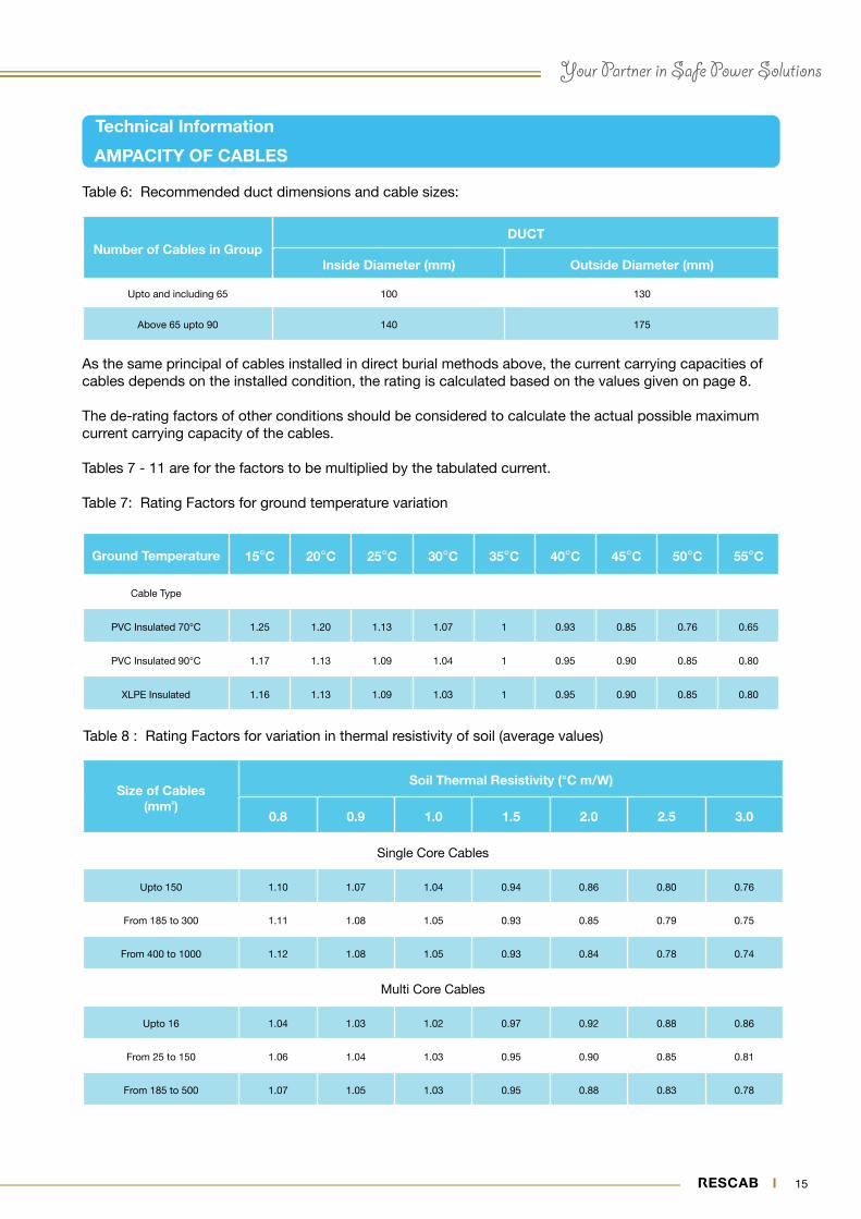
A duct is an enclosure of metal or insulating material other than conduits or cable trunking, intended for the protection of cables which are drawn in after errection of the ducting. The recommended relation between the cable size and duct size is as in table 6.
A
14 15
Your Partner in Safe Power Solutions
Technical Information
AMPACITY OF CABLES
As the same principal of cables installed in direct burial methods above, the current carrying capacities of cables depends on the installed condition, the rating is calculated based on the values given on page 8.
The de-rating factors of other conditions should be considered to calculate the actual possible maximum current carrying capacity of the cables.
Tables 7 - 11 are for the factors to be multiplied by the tabulated current.
Table 7: Rating Factors for ground temperature variation
Number of Cables in GroupDUCT
Inside Diameter (mm) Outside Diameter (mm)
Upto and including 65 100 130
Above 65 upto 90 140 175
Ground Temperature 15°C 20°C 25°C 30°C 35°C 40°C 45°C 50°C 55°C
Cable Type
PVC Insulated 70°C 1.25 1.20 1.13 1.07 1 0.93 0.85 0.76 0.65
PVC Insulated 90°C 1.17 1.13 1.09 1.04 1 0.95 0.90 0.85 0.80
XLPE Insulated 1.16 1.13 1.09 1.03 1 0.95 0.90 0.85 0.80
Table 8 : Rating Factors for variation in thermal resistivity of soil (average values)
Table 6: Recommended duct dimensions and cable sizes:
Size of Cables (mm²)
Soil Thermal Resistivity (°C m/W)
0.8 0.9 1.0 1.5 2.0 2.5 3.0
Single Core Cables
Upto 150 1.10 1.07 1.04 0.94 0.86 0.80 0.76
From 185 to 300 1.11 1.08 1.05 0.93 0.85 0.79 0.75
From 400 to 1000 1.12 1.08 1.05 0.93 0.84 0.78 0.74
Multi Core Cables
Upto 16 1.04 1.03 1.02 0.97 0.92 0.88 0.86
From 25 to 150 1.06 1.04 1.03 0.95 0.90 0.85 0.81
From 185 to 500 1.07 1.05 1.03 0.95 0.88 0.83 0.78

16 17
Technical Information
AMPACITY OF CABLES
Table 9 : Rating Factors of depth of Laying (to center of duct or trefoil group of ducts)
Depth of Laying of Cables (m) Single Core Cables Multi Core Cables
0.50 1.00 1.00
0.60 0.98 0.99
0.80 0.95 0.98
1.00 0.93 0.96
1.25 0.91 0.95
1.50 0.89 0.94
1.75 0.88 0.94
2.00 0.87 0.93
2.50 0.86 0.92
3.00 or more 0.85 0.91
Table10: Group rating factors for single core cables in trefoil single way ducts, horizontal formation (average values)
Number of Circuits
Cable to Cable Clearance A
Touching 0.45 m 0.60 m
2 0.87 0.91 0.93
3 0.78 0.84 0.87
4 0.74 0.81 0.85
5 0.70 0.79 0.83
6 0.69 0.78 0.82
SpacingA

16 17
Your Partner in Safe Power Solutions
Technical Information
AMPACITY OF CABLES
Table 11: Group rating factors for Multicore cables in single way ducts horizontal formation (average values)
Number of Cables in Group
Cable to Cable Clearance A
Cables Touching 0.30 m 0.45 m 0.60 m
2 0.90 0.93 0.95 0.96
3 0.83 0.88 0.91 0.93
4 0.79 0.85 0.89 0.92
5 0.75 0.83 0.88 0.91
6 0.73 0.82 0.87 0.90
2 0.88 0.91 0.93 0.94
3 0.80 0.85 0.88 0.90
4 0.76 0.81 0.85 0.88
5 0.72 0.78 0.83 0.86
6 0.69 0.76 0.81 0.85
SpacingA

18 19
Technical Information
AMPACITY OF CABLES
4.0 INSTALLATION CONDITIONS FOR CABLES IN AIR
Cables installed in air could have many forms of installation methods as described in BS 7671 IEE wiring regulation 17th edition. Some of these methods are like A or B (for cables on Trefoil format laying as in table 12) or like C or D (For cables Laid Flat vertically or horizontally as in table 12). It is assumed that the cables are not exposed to the direct sunlight and away from any external heat sources.
Table 12: Installation Method for Cables
Installation Method DescriptionCurrent carrying Capacity
Reference Method
Single Core or multi core cables:
Fixed on (Clipped direct) or space less than 0.3 times the cable diameter from a wall
A
Multi Core cable in conduit, spaced less than 0.3 times conduit diameter B
Cables run horizontally or vertically flat on perforated tray
For multi core cable De= Cable diameter, And for 3 single core cables De = 3 times cable diameter
C OR D

18 19
Your Partner in Safe Power Solutions
Technical Information
AMPACITY OF CABLES
Important note for Single core cables:
The conductors of an A.C. circuit installed in an Iron pipes or ferromagnetic enclosure shall be arranged so that all line conductors and the neutral conductor, if any, and the appropriate protective conductor are contained in the same enclosure.
When such conductors enter an Iron pipes or ferrous enclosure, they shall be arranged such that the conductors are only collectively surrounded by ferrous material.
Table 13: Rating factors for other ambient air temperatures
Air Temperature 25°C 30°C 35°C 40°C 45°C 50°C 55°C 60°C
Cable Type
PVC Insulated 70°C 1.22 1.15 1.08 1.00 0.91 0.82 0.71 0.58
PVC Insulated 90°C 1.14 1.10 1.05 1.00 0.95 0.90 0.84 0.78
XLPE Insulated 1.14 1.10 1.05 1.00 0.95 0.90 0.84 0.78
20 21
Technical Information
AMPACITY
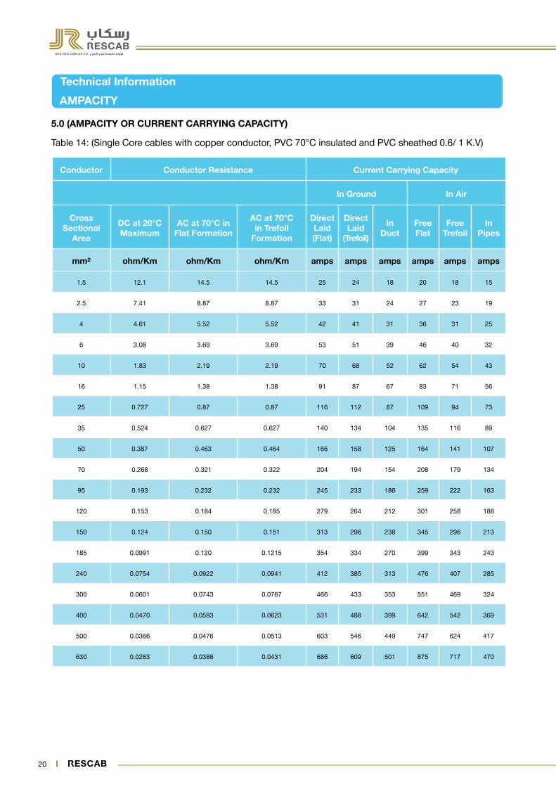
5.0 (AMPACITY OR CURRENT CARRYING CAPACITY)
Table 14: (Single Core cables with copper conductor, PVC 70°C insulated and PVC sheathed 0.6/ 1 K.V)
Conductor Conductor Resistance Current Carrying Capacity
In Ground In Air
Cross Sectional
Area
DC at 20°C Maximum
AC at 70°C in Flat Formation
AC at 70°C in Trefoil
Formation
Direct Laid(Flat)
Direct Laid
(Trefoil)
In Duct
Free Flat
Free Trefoil
In Pipes
mm² ohm/Km ohm/Km ohm/Km amps amps amps amps amps amps
1.5 12.1 14.5 14.5 25 24 18 20 18 15
2.5 7.41 8.87 8.87 33 31 24 27 23 19
4 4.61 5.52 5.52 42 41 31 36 31 25
6 3.08 3.69 3.69 53 51 39 46 40 32
10 1.83 2.19 2.19 70 68 52 62 54 43
16 1.15 1.38 1.38 91 87 67 83 71 56
25 0.727 0.87 0.87 116 112 87 109 94 73
35 0.524 0.627 0.627 140 134 104 135 116 89
50 0.387 0.463 0.464 166 158 125 164 141 107
70 0.268 0.321 0.322 204 194 154 208 179 134
95 0.193 0.232 0.232 245 233 186 259 222 163
120 0.153 0.184 0.185 279 264 212 301 258 188
150 0.124 0.150 0.151 313 296 238 345 296 213
185 0.0991 0.120 0.1215 354 334 270 399 343 243
240 0.0754 0.0922 0.0941 412 385 313 476 407 285
300 0.0601 0.0743 0.0767 466 433 353 551 469 324
400 0.0470 0.0593 0.0623 531 488 399 642 542 369
500 0.0366 0.0476 0.0513 603 546 449 747 624 417
630 0.0283 0.0386 0.0431 686 609 501 875 717 470

20 21
Your Partner in Safe Power Solutions
Technical Information
AMPACITY
Table 15: (Three and Four core cable with copper conductor, PVC 70°C insulated and PVC sheathed 0.6 / 1K.V)
Conductor Conductor Resistance In Ground In Air
Unarmoured Armoured Unarmoured Armoured
Cross Sectional
Area
DC at 20°C Maximum
AC at 70°C Direct Laid
Laid in
Duct
Direct Laid
Free In pipes
Method AFree
mm² ohm/Km ohm/Km amps amps amps amps amps amps
1.5 12.1 14.5 21 18 - 16 14 -
2.5 7.41 8.87 27 23 - 22 19 -
4 4.61 5.52 36 30 36 29 24 29
6 3.08 3.69 45 37 45 37 31 37
10 1.83 2.19 60 50 60 50 41 51
16 1.15 1.38 78 65 78 66 54 66
25 0.727 0.87 100 83 100 87 70 88
35 0.524 0.628 125 101 124 106 84 109
50 0.387 0.464 149 121 147 130 102 133
70 0.268 0.323 183 148 180 163 126 167
95 0.193 0.232 219 178 215 201 154 204
120 0.153 0.185 249 203 245 233 177 235
150 0.124 0.151 280 229 273 268 202 268
185 0.0991 0.121 315 259 306 308 230 305
240 0.0754 0.0939 364 301 349 364 269 355
300 0.0601 0.0764 409 339 387 417 306 401
400 0.0470 0.0619 465 386 428 485 352 454
500 0.0366 0.0507 520 441 468 554 406 506

22 23
Technical Information
AMPACITY
Table 16: (Single Core cables with copper conductor, XLPE insulated and PVC sheathed, 0.6 / 1 K.V)
Conductor Conductor Resistance Current Carrying Capacity
In Ground In Air
Cross Sectional
Area
DC at 20°C Maximum
AC at 90°C in Flat Formation
AC at 90°C in Trefoil
Formation
Direct Laid(Flat)
Direct Laid
(Trefoil)
In Duct
Free Flat
Free Trefoil
In Pipes
mm² ohm/Km ohm/Km ohm/Km amps amps amps amps amps amps
1.5 12.1 15.2 15.2 31 30 22 27 22 19
2.5 7.41 9.45 9.45 40 39 29 36 29 24
4 4.61 5.88 5.88 52 50 38 47 38 32
6 3.08 3.93 3.93 65 63 47 60 49 40
10 1.83 2.33 2.33 87 83 63 82 66 54
16 1.15 1.47 1.47 112 107 82 109 88 70
25 0.727 0.927 0.927 144 137 105 145 116 92
35 0.524 0.668 0.669 172 165 127 178 143 112
50 0.387 0.494 0.494 204 195 151 218 175 134
70 0.268 0.342 0.343 251 238 187 277 222 168
95 0.193 0.247 0.248 301 286 225 344 274 205
120 0.153 0.196 0.197 345 327 258 409 326 237
150 0.124 0.159 0.160 385 363 290 461 367 269
185 0.0991 0.128 0.129 436 410 330 534 425 308
240 0.0754 0.098 0.100 507 447 382 638 505 361
300 0.0601 0.079 0.0815 573 532 431 740 583 411
400 0.0470 0.0629 0.0661 645 600 489 865 676 469
500 0.0366 0.0504 0.0543 744 673 550 1009 779 533
630 0.0283 0.0407 0.0453 847 752 615 1184 900 603

22 23
Your Partner in Safe Power Solutions
Technical Information
AMPACITY
Table 17: (Three and Four core cable with copper conductor, XLPE insulated and PVC sheathed, 0.6 / 1 KV)
Conductor Conductor Resistance In Ground In Air
Unarmoured Armoured Unarmoured Armoured
Cross Sectional
Area
DC at 20°C Maximum
AC at 90°C Direct Laid
Laid in
DuctDirect Laid Free
In pipes
Free
mm² ohm/Km ohm/Km amps amps amps amps amps amps
1.5 12.1 15.4 27 22 - 22 18 -
2.5 7.41 9.45 35 29 - 29 24 -
4 4.61 5.88 45 37 46 38 31 39
6 3.08 3.93 56 46 57 48 39 50
10 1.83 2.33 76 62 76 67 52 67
16 1.15 1.47 98 80 98 88 68 89
25 0.727 0.927 128 104 128 118 90 120
35 0.524 0.669 157 125 158 142 107 149
50 0.387 0.494 187 149 188 175 129 182
70 0.268 0.343 229 183 229 220 161 229
95 0.193 0.248 276 220 274 272 196 280
120 0.153 0.197 313 251 310 316 226 322
150 0.124 0.160 350 283 346 363 258 368
185 0.0991 0.129 395 321 387 418 295 420
240 0.0754 0.0998 458 372 444 496 346 491
300 0.0601 0.0812 516 420 494 571 394 557
400 0.0470 0.0656 584 478 549 665 454 635
500 0.0366 0.0536 655 538 597 760 515 705

24 25
Technical Information
AMPACITY
Table 18: (Single Core cables with Aluminium conductor, XLPE insulated and PVC sheathed, 0.6 / 1 K.V)
Conductor Conductor Resistance Current Carrying Capacity
In Ground In Air
Cross Sectional
Area
DC at 20°C Maximum
AC at 90°C in Flat Formation
AC at 90°C in Trefoil
Formation
Direct Laid(Flat)
Direct Laid
(Trefoil)
In Duct
Free Flat
Free Trefoil
In Pipes
mm² ohm/Km ohm/Km ohm/Km amps amps amps amps amps amps
16 1.91 2.45 2.45 87 83 63 85 68 54
25 1.2 1.54 1.54 111 107 82 112 90 71
35 0.868 1.113 1.113 133 128 98 138 111 87
50 0.641 0.822 0.822 158 151 117 169 135 104
70 0.443 0.568 0.569 194 185 145 215 172 131
95 0.32 0.411 0.411 233 222 175 266 213 159
120 0.253 0.325 0.325 266 252 201 312 249 184
150 0.206 0.265 0.265 298 282 226 357 285 209
185 0.164 0.211 0.212 339 320 257 416 332 241
240 0.125 0.161 0.163 395 371 300 497 396 283
300 0.100 0.130 0.131 448 419 340 578 459 324
400 0.0778 0.1016 0.1037 514 479 390 681 540 375
500 0.0605 0.0799 0.0826 590 546 446 801 631 432
630 0.0469 0.0632 0.0666 681 621 509 954 746 498

24 25
Your Partner in Safe Power Solutions
Technical Information
AMPACITY
Table 19: (Three and Four core cable with Aluminium conductor, XLPE insulated and PVC sheathed, 0.6/ 1 KV)
Conductor Conductor Resistance In Ground In Air
Unarmoured Armoured Unarmoured Armoured
Cross Sectional
Area
DC at 20°C Maximum
AC at 90°C Direct Laid
Laid in Duct
Direct Laid
Free In pipes Free
mm² ohm/Km ohm/Km amps amps amps amps amps amps
16 1.91 2.45 76 62 76 68 53 69
25 1.20 1.54 99 81 99 92 70 93
35 0.868 1.113 121 96 122 110 83 115
50 0.641 0.822 145 116 146 136 100 141
70 0.443 0.569 178 142 178 171 125 178
95 0.320 0.411 214 171 213 211 152 218
120 0.253 0.325 243 195 242 246 176 252
150 0.206 0.265 272 220 270 282 200 288
185 0.164 0.212 309 250 305 326 230 331
240 0.125 0.163 359 282 352 388 271 390
300 0.100 0.131 406 331 395 449 310 445
400 0.0778 0.1034 466 381 447 530 362 516
500 0.0605 0.0822 529 434 497 614 416 586

26 27
Technical Information
6.0 Voltage Drop
Voltage drop is one the important factor to be considered for cable selection. According to BS 7671 IEE Wiring Regulation 17th edition under normal service conditions the voltage at the terminals of any fixed current-using equipment shall be greater than the lower limit corresponding to the product standard relevant to the equipment and where fixed current using equipment is not the subject of product standard the voltage at the terminals shall be such as not to impair the safe functioning of the equipment.
Table 20: (Approximate voltage drop at 60 Hz for single core stranded plain Copper/ Aluminium conductors, PVC insulated, PVC sheathed).
Nominal Area of Conductor
Copper Conductor mV/ amp/ m Aluminium Conductor mV/ amp/ m
PVC Rated 70° C PVC Rated 70° C PVC Rated 70° C PVC Rated 70° C
mm² Flat Trefoil Flat Trefoil
1.5 22.6 22.5 - -
2.5 13.9 13.8 - -
4 8.70 8.70 - -
6 5.80 5.80 - -
10 3.50 3.50 - -
16 2.30 2.20 3.70 3.70
25 1.50 1.50 2.40 2.30
35 1.10 1.10 1.70 1.70
50 0.83 0.82 1.30 1.30
70 0.61 0.6 0.94 0.92
95 0.47 0.45 0.71 0.69
120 0.39 0.38 0.58 0.56
150 0.34 0.33 0.49 0.48
185 0.29 0.28 0.41 0.4
240 0.25 0.24 0.34 0.33
300 0.22 0.21 0.29 0.28
400 0.2 0.18 0.25 0.24
500 0.18 0.17 0.22 0.21
630 0.16 0.15 0.19 0.18

26 27
Your Partner in Safe Power Solutions
Technical Information
Voltage Drop
Table 21: (Approximate voltage drop at 60 Hz for Three and Four core stranded plain copper/ aluminium conductors, PVC insulated, PVC sheathed).
Nominal Area of Conductor
Copper Conductor Aluminium Conductor
mV/ amp/ m mV/ amp/ m
mm² PVC Rated 70 °C PVC Rated 70 °C
1.5 22.6 -
2.5 13.8 -
4 8.60 -
6 5.80 -
10 3.50 -
16 2.20 3.60
25 1.40 2.30
35 1.10 1.70
50 0.80 1.30
70 0.58 0.91
95 0.44 0.68
120 0.37 0.55
150 0.32 0.47
185 0.27 0.39
240 0.23 0.32
300 0.20 0.27
400 0.18 0.23
500 0.15 0.2

28 29
Technical Information
Voltage Drop
Table 22: (Approximate voltage drop at 60 Hz for single core stranded plain copper/ aluminium conductors, XLPE insulated, PVC sheathed).
Nominal Area of Conductor
Copper Conductor mV/ amp/ m Aluminium Conductor mV/ amp/ m
XLPE Rated 90°C XLPE Rated 90°C XLPE Rated 90°C XLPE Rated 90°C
mm² Flat Trefoil Flat Trefoil
1.5 22.9 22.8 - -
2.5 14.1 14.1 - -
4 8.80 8.70 - -
6 5.90 5.90 - -
10 3.60 3.60 - -
16 2.30 2.30 3.70 3.70
25 1.50 1.50 2.40 2.40
35 1.10 1.10 1.80 1.70
50 0.84 0.83 1.30 1.30
70 0.61 0.6 0.95 0.93
95 0.47 0.46 0.71 0.7
120 0.39 0.38 0.58 0.57
150 0.34 0.33 0.5 0.48
185 0.29 0.28 0.42 0.4
240 0.25 0.24 0.34 0.33
300 0.22 0.21 0.29 0.28
400 0.19 0.18 0.25 0.24
500 0.17 0.16 0.22 0.21
630 0.16 0.15 0.19 0.18

28 29
Your Partner in Safe Power Solutions
Technical Information
Voltage Drop
Table 23: (Approximate voltage drop at 60 Hz for Three and Four core stranded plain copper/ aluminium conductors, XLPE insulated, PVC sheathed).
Nominal Area of Conductor
Copper Conductor Aluminium Conductor
mV/ amp/ m mV/ amp/ m
mm² XLPE Rated 90° C XLPE Rated 90° C
1.5 22.8 -
2.5 14 -
4 8.70 -
6 5.90 -
10 3.50 -
16 2.20 3.70
25 1.50 2.40
35 1.10 1.70
50 0.81 1.30
70 0.58 0.92
95 0.44 0.68
120 0.37 0.56
150 0.31 0.47
185 0.27 0.39
240 0.23 0.32
300 0.2 0.27
400 0.18 0.23
500 0.15 0.2

30 31
Technical Information
7.0 (Short Circuit Rating - Conductors)
Short circuit rating is based on, IEC 60724. for an insulated conductor with operating temperature of 70 °C for PVC and 90 °C for XLPE, the maximum temperature during the fault is 140 °C or 160 °C for PVC insulated cables, small sizes and big sizes respectively, and up to 250 °C for XLPE cables.
Tables 24 and 25 represents the short circuit current rating at duration of fault time equal to 1 second. For any other values graph 1,2,3 and 4 may be used.
Table 24: (PVC Insulated 70 °C type TI-1 or 90 °C type TI-3) cables copper and Aluminium conductor).
Conductor Size
Short circuit ratings for 1 second in k amp
Copper Conductor Aluminium Conductor
10 1.03 0.68
16 1.65 1.09
25 2.58 1.7
35 3.60 2.38
50 5.15 3.40
70 7.21 1.76
95 9.79 6.46
120 12.36 8.16
150 15.45 10.2
185 19.1 12.6
240 24.72 16.32
300 34.5 22.8
400 46.00 30.4
500 57.5 38.0
630 72.45 47.88
800 92.0 60.8
1000 115 76.00

30 31
Your Partner in Safe Power Solutions
Technical Information
Short Circuit Rating - Conductors
Table 25: XLPE cables copper and Aluminium conductor.
Conductor Size
Short circuit ratings for 1 second in k amp
Copper Conductor Aluminium Conductor
10 1.43 0.94
16 2.29 1.50
25 3.58 2.35
35 5.00 3.29
50 7.15 4.70
70 10.01 6.58
95 13.59 8.93
120 17.16 11.28
150 21.45 14.10
185 26.46 17.39
240 34.32 22.56
300 42.90 28.20
400 57.20 37.60
500 71.5 47
630 90.09 59.22
800 114.40 75.20
1000 143.00 94.00

32 33
Technical Information
Short Circuit Rating - Conductors
Graph 1: PVC (70 °C type) insulated cables short circuit (Copper Conductor)

32 33
Your Partner in Safe Power Solutions
Technical Information
Short Circuit Rating - Conductors
Graph 2: PVC (70 °C type) insulated cables short circuit (Aluminium Conductor)

34 35
Technical Information
Short Circuit Rating - Conductors
Graph 3: XLPE insulated cables short circuit (Copper Conductor)

34 35
Your Partner in Safe Power Solutions
Technical Information
Short Circuit Rating - Conductors
Graph 4: XLPE insulated cables short circuit (Aluminium Conductor)

36 37
Part 2: Product Range

36 37
Your Partner in Safe Power Solutions
Soft Drawn Bare Stranded Conductor
Copper SDBC Conductor
IEC 60228
Nominal Cross Section Area of
Conductor
No. & Nominal Diameter of
Wires
Approximate Overall Daimeter
Maximum DC Resistance at
20° C
Net Approx. Weight
Standard Packing
mm² No.x mm mm Ω/Km Kg/Km m
2.5 7 x 0.66 2.0 7.41 21 2000
4 7 x 0.84 2.5 4.61 34 2000
6 7 x 1.02 3.1 3.08 51 2000
10 7 x 1.33 4.0 1.83 86 2000
16 7 x 1.68 5.1 1.15 137 2000
25 7 x 2.11 6.4 0.727 217 2000
35 7 x 2.48 7.5 0.524 312 2000
50 19 x 1.75 8.8 0.387 408 1000
70 19 x 2.11 10.6 0.268 589 1000
95 19 x 2.48 12.4 0.193 818 1000
120 37 x 2.00 14.0 0.153 1032 1000
150 37 x 2.22 15.5 0.124 1273 1000
185 37 x 2.48 17.4 0.099 1593 1000
240 61 x 2.22 20.3 0.075 2094 1000
300 61 x 2.48 22.9 0.060 2650 1000
400 61 x 2.81 25.7 0.047 3400 500
500 61 x 3.18 28.8 0.037 4314 500
38 39
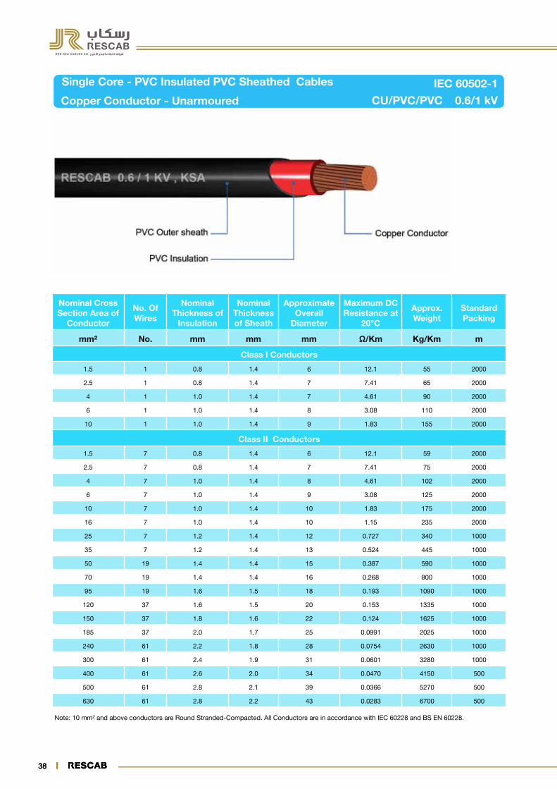
Single Core - PVC Insulated PVC Sheathed Cables
Copper Conductor - Unarmoured CU/PVC/PVC 0.6/1 kV
IEC 60502-1
Nominal Cross Section Area of
Conductor
No. Of Wires
Nominal Thickness of
Insulation
Nominal Thickness of Sheath
Approximate Overall
Diameter
Maximum DC Resistance at
20°C
Approx. Weight
Standard Packing
mm² No. mm mm mm Ω/Km Kg/Km m
Class I Conductors
1.5 1 0.8 1.4 6 12.1 55 2000
2.5 1 0.8 1.4 7 7.41 65 2000
4 1 1.0 1.4 7 4.61 90 2000
6 1 1.0 1.4 8 3.08 110 2000
10 1 1.0 1.4 9 1.83 155 2000
Class II Conductors
1.5 7 0.8 1.4 6 12.1 59 2000
2.5 7 0.8 1.4 7 7.41 75 2000
4 7 1.0 1.4 8 4.61 102 2000
6 7 1.0 1.4 9 3.08 125 2000
10 7 1.0 1.4 10 1.83 175 2000
16 7 1.0 1.4 10 1.15 235 2000
25 7 1.2 1.4 12 0.727 340 1000
35 7 1.2 1.4 13 0.524 445 1000
50 19 1.4 1.4 15 0.387 590 1000
70 19 1.4 1.4 16 0.268 800 1000
95 19 1.6 1.5 18 0.193 1090 1000
120 37 1.6 1.5 20 0.153 1335 1000
150 37 1.8 1.6 22 0.124 1625 1000
185 37 2.0 1.7 25 0.0991 2025 1000
240 61 2.2 1.8 28 0.0754 2630 1000
300 61 2.4 1.9 31 0.0601 3280 1000
400 61 2.6 2.0 34 0.0470 4150 500
500 61 2.8 2.1 39 0.0366 5270 500
630 61 2.8 2.2 43 0.0283 6700 500
Note: 10 mm² and above conductors are Round Stranded-Compacted. All Conductors are in accordance with IEC 60228 and BS EN 60228.
3838

38 39
Your Partner in Safe Power Solutions
3939
Two Cores - PVC Insulated PVC Sheathed Cables
Copper Conductor - Unarmoured CU/PVC/PVC 0.6/1 kV
IEC 60502-1
Note: 10 mm² and above conductors are Round Stranded-Compacted. All Conductors are in accordance with IEC 60228 and BS EN 60228
No. of Cores x Nominal Cross Section Area
No. Of Wires
Nominal Thickness of
Insulation
Nominal Thickness of Sheath
Approximate Overall
Diameter
Maximum DC Resistance at
20°C
Approx. Weight
Standard Packing
mm² No. mm mm mm Ω/Km Kg/Km m
Class I Conductors
2x1.5 1 0.8 1.8 12 12.1 200 1000
2x2.5 1 0.8 1.8 13 7.41 225 1000
2x4 1 1.0 1.8 15 4.61 325 1000
2x6 1 1.0 1.8 16 3.08 375 1000
2x10 1 1.0 1.8 18 1.83 500 1000
Class II Conductors
2x1.5 7 0.8 1.8 13 12.1 215 1000
2x2.5 7 0.8 1.8 14 7.41 260 1000
2x4 7 1.0 1.8 16 4.61 350 1000
2x6 7 1.0 1.8 17 3.08 425 1000
2x10 7 1.0 1.8 19 1.83 560 1000
2x16 7 1.0 1.8 21 1.15 730 1000
2x25 7 1.2 1.8 24 0.727 960 1000
2x35 7 1.2 1.8 26 0.524 1210 1000

Three Cores - PVC Insulated PVC Sheathed Cables
Copper Conductor - Unarmoured CU/PVC/PVC 0.6/1 kV
IEC 60502-1
No. of Cores x Nominal Cross Section Area
No. Of Wires
Nominal Thickness of
Insulation
Nominal Thickness of Sheath
Approximate Overall
Diameter
Maximum DC Resistance
at 20°C
Approx. Weight
Standard Packing
mm² No. mm mm mm Ω/Km Kg/Km m
Class I Conductors
3x1.5 1 0.8 1.8 13 12.1 225 1000
3x2.5 1 0.8 1.8 14 7.41 275 1000
3x4 1 1.0 1.8 16 4.61 375 1000
3x6 1 1.0 1.8 17 3.08 450 1000
3x10 1 1.0 1.8 20 1.83 600 1000
Class II Conductors
3x1.5 7 0.8 1.8 13 12.1 240 1000
3x2.5 7 0.8 1.8 14 7.41 295 1000
3x4 7 1.0 1.8 16 4.61 405 1000
3x6 7 1.0 1.8 18 3.08 500 1000
3x10 7 1.0 1.8 20 1.83 675 1000
3x16 7 1.0 1.8 22 1.15 880 1000
3x25 7 1.2 1.8 25 0.727 1280 1000
3x35 7 1.2 1.8 28 0.524 1640 1000
3x50 7 1.4 1.8 31 0.387 1980 500
3x70 19 1.4 1.9 35 0.268 2690 500
3x95 19 1.6 2.1 40 0.193 3630 500
3x120 37 1.6 2.2 43 0.153 4420 500
3x150 37 1.8 2.3 48 0.124 5470 500
3x185 37 2.0 2.5 52 0.0991 6750 250
3x240 61 2.2 2.7 59 0.0754 8770 250
3x300 61 2.4 2.9 65 0.0601 10840 250
3x400 61 2.6 3.1 73 0.0470 13770 250
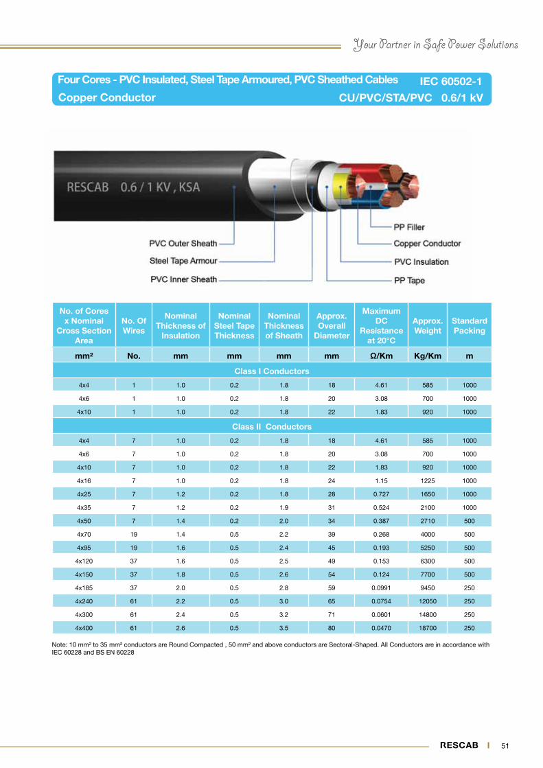
Note: 10 mm² to 35 mm² conductors are Round Compacted , 50 mm² and above conductors are Sectoral-Shaped. All Conductors are in accordance with IEC 60228 and BS EN 60228.
40

Your Partner in Safe Power Solutions
41
Note: 10 mm² to 35 mm² conductors are Round Compacted , 50 mm² and above conductors are Sectoral-Shaped. All Conductors are in accordance with IEC 60228 and BS EN 60228
Four Cores - PVC Insulated PVC Sheathed Cables
Copper Conductor - Unarmoured CU/PVC/PVC 0.6/1 kV
IEC 60502-1
No. of Cores x Nominal Cross Section Area
No. Of Wires
Nominal Thickness of
Insulation
Nominal Thickness of Sheath
Approximate Overall
Diameter
Maximum DC Resistance at
20°C
Approx. Weight
Standard Packing
mm² No. mm mm mm Ω/Km Kg/Km m
Class I Conductors
4x1.5 1 0.8 1.8 14 12.1 280 1000
4x2.5 1 0.8 1.8 15 7.41 345 1000
4x4 1 1.0 1.8 17 4.61 475 1000
4x6 1 1.0 1.8 18 3.08 595 1000
4x10 1 1.0 1.8 20 1.83 820 1000
Class II Conductors
4x1.5 7 0.8 1.8 14 12.1 280 1000
4x2.5 7 0.8 1.8 15 7.41 350 1000
4x4 7 1.0 1.8 18 4.61 480 1000
4x6 7 1.0 1.8 19 3.08 600 1000
4x10 7 1.0 1.8 21 1.83 820 1000
4x16 7 1.0 1.8 23 1.15 1090 1000
4x25 7 1.2 1.8 28 0.727 1490 1000
4x35 7 1.2 1.8 30 0.524 1920 1000
4x50 7 / 19 1.4 1.9 33 0.387 2480 500
4x70 19 1.4 2.1 37 0.268 3400 500
4x95 19 1.6 2.2 42 0.193 4550 500
4x120 37 1.6 2.3 46 0.153 5600 500
4x150 37 1.8 2.5 50 0.124 6900 500
4x185 37 2.0 2.7 56 0.0991 8600 250
4x240 61 2.2 2.9 62 0.0754 11100 250
4x300 61 2.4 3.1 68 0.0601 13760 250
4x400 61 2.6 3.4 77 0.0470 17500 250

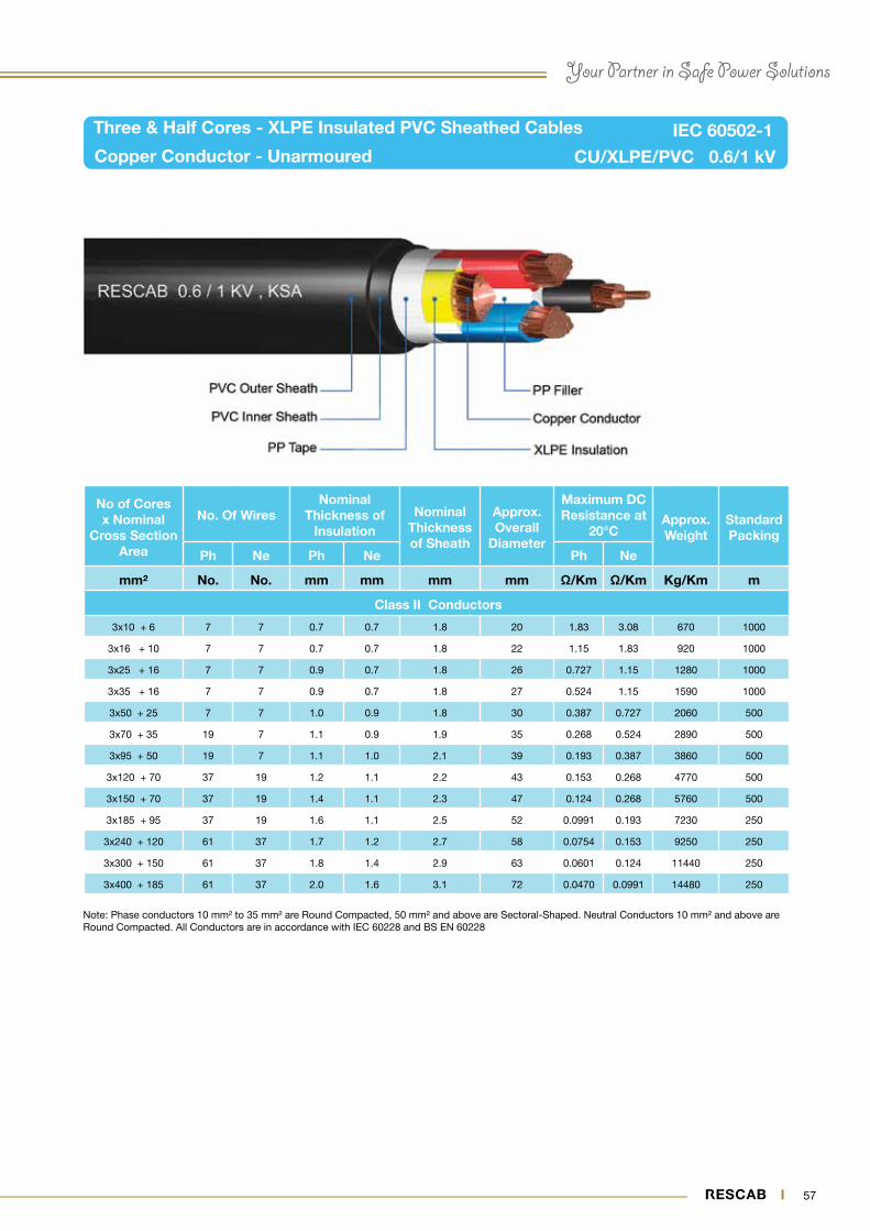
Three & Half Cores - PVC Insulated PVC Sheathed Cables
Copper Conductor - Unarmoured CU/PVC/PVC 0.6/1 kVIEC 60502-1
Note: Phase conductors 10 mm² to 35 mm² are Round Compacted, 50 mm² and above are Sectoral-Shaped. Neutral Conductors 10 mm² and above are Round Compacted. All Conductors are in accordance with IEC 60228 and BS EN 60228
No of Cores x Nominal
Cross Section Area
No. Of WiresNominal
Thickness of Insulation
Nominal Thickness of Sheath
Approx. Overall
Diameter
Maximum DC Resistance at
20°CApprox. Weight
Standard Packing
Ph Ne Ph Ne Ph Ne
mm² No. No. mm mm mm mm Ω/Km Ω/Km Kg/Km m
Class II Conductors
3x10 + 6 7 7 1.0 1.0 1.8 21 1.83 3.08 770 1000
3x16 + 10 7 7 1.0 1.0 1.8 23 1.15 1.83 1030 1000
3x25 + 16 7 7 1.2 1.0 1.8 27 0.727 1.15 1375 1000
3x35 + 16 7 7 1.2 1.0 1.8 29 0.524 1.15 1690 1000
3x50 + 25 7 7 1.4 1.2 1.9 32 0.387 0.727 2200 500
3x70 + 35 19 7 1.4 1.2 2.0 36 0.268 0.524 3020 500
3x95 + 50 19 7 1.6 1.4 2.2 40 0.193 0.387 4060 500
3x120 + 70 37 19 1.6 1.4 2.3 44 0.153 0.268 5080 500
3x150 + 70 37 19 1.8 1.4 2.4 48 0.124 0.268 6050 500
3x185 + 95 37 19 2.0 1.6 2.6 53 0.0991 0.193 7580 250
3x240 + 120 61 37 2.2 1.6 2.8 59 0.0754 0.153 9780 250
3x300 + 150 61 37 2.4 1.8 3.0 65 0.0601 0.124 12090 250
3x400 + 185 61 37 2.6 2.0 3.2 74 0.0470 0.0991 15270 250
42

Your Partner in Safe Power Solutions
43
Note: 10 mm² and above conductors are Round Stranded-Compacted. All Conductors are in accordance with IEC 60228 and BS EN 60228
Single Core - PVC Insulated, AL Wire Armoured PVC Sheathed Cables
Copper Conductor CU/PVC/AWA/PVC 0.6/1 kV
IEC 60502-1
Nominal Cross Section
Area of Conductor
No. Of Wires
Nominal Thickness
of Insulation
Nominal Aluminium Wire Dia.
Nominal Thickness of Sheath
Approx. Overall
Diameter
Maximum DC Resistance at
20°C
Approx. Weight
Standard Packing
mm² No. mm mm mm mm Ω/Km Kg/Km m
Class II Conductors
10 7 1.0 0.8 1.8 14 1.83 310 2000
16 7 1.0 0.8 1.8 15 1.15 380 2000
25 7 1.2 0.8 1.8 16 0.727 510 1000
35 7 1.2 0.8 1.8 18 0.524 640 1000
50 19 1.4 1.25 1.8 20 0.387 860 1000
70 19 1.4 1.25 1.8 22 0.268 1100 1000
95 19 1.6 1.6 1.8 24 0.193 1420 1000
120 37 1.6 1.8 1.8 26 0.153 1740 1000
150 37 1.8 1.8 1.8 28 0.124 2080 1000
185 37 2.0 1.8 1.8 32 0.0991 2510 1000
240 61 2.2 1.8 1.9 34 0.0754 3180 1000
300 61 2.4 2.0 2.0 37 0.0601 4000 500
400 61 2.6 2.0 2.1 41 0.0470 4990 500
500 61 2.8 2.0 2.2 45 0.03766 6200 500
630 61 2.8 2.0 2.4 51 0.0283 7800 500

44 45
Note: 10 mm² and above conductors are Round Stranded-Compacted. All Conductors are in accordance with IEC 60228 and BS EN 60228
Two Cores - PVC Insulated, Steel Wire Armoured PVC Sheathed Cables
Copper Conductor CU/PVC/SWA/PVC 0.6/1 kV
IEC 60502-1
No. of Cores x Nominal Cross Section Area
No. Of Wires
Nominal Thickness
of Insulation
Nominal Steel
Wire Dia.
Nominal Thickness of Sheath
Approx. Overall
Diameter
Maximum DC
Resistance at 20°C
Approx. Weight
Standard Packing
mm² No. mm mm mm mm Ω/Km Kg/Km m
Class I Conductors
2x4 1 1.0 0.8 1.8 17 4.61 540 1000
2x6 1 1.0 1.25 1.8 19 3.08 800 1000
2x10 1 1.0 1.25 1.8 21 1.83 980 1000
Class II Conductors
2x2.5 7 0.8 0.8 1.8 15 7.41 440 1000
2x4 7 1.0 0.8 1.8 17 4.61 540 1000
2x6 7 1.0 1.25 1.8 19 3.08 800 1000
2x10 7 1.0 1.25 1.8 21 1.83 980 1000
2x16 7 1.0 1.25 1.8 23 1.15 1190 1000
2x25 7 1.2 1.6 1.8 27 0.727 1760 1000
2x35 7 1.2 1.6 1.8 29 0.524 2125 1000

44 45
Your Partner in Safe Power Solutions
Note: 10 mm² to 35 mm² conductors are Round Compacted , 50 mm² and above conductors are Sectoral-Shaped. All Conductors are in accordance with IEC 60228 and BS EN 60228.
Three Cores - PVC Insulated, Steel Wire Armoured, PVC Sheathed Cables
Copper Conductor CU/PVC/SWA/PVC 0.6/1 kV
IEC 60502-1
No. of Cores x Nominal Cross Section Area
No. Of Wires
Nominal Thickness of
Insulation
Nominal Steel
Wire Dia.
Nominal Thickness of Sheath
Approx. Overall
Diameter
Maximum DC
Resistance at 20°C
Approx. Weight
Standard Packing
mm² No. mm mm mm mm Ω/Km Kg/Km m
Class I Conductors
3x2.5 1 0.8 0.8 1.8 16 7.41 480 1000
3x4 1 1.0 1.25 1.8 18 4.61 740 1000
3x6 1 1.0 1.25 1.8 19 3.08 870 1000
3x10 1 1.0 1.25 1.8 22 1.83 1070 1000
Class II Conductors
3x2.5 7 0.8 0.8 1.8 16 7.41 480 1000
3x4 7 1.0 1.25 1.8 19 4.61 740 1000
3x6 7 1.0 1.25 1.8 20 3.08 890 1000
3x10 7 1.0 1.25 1.8 23 1.83 1090 1000
3x16 7 1.0 1.25 1.8 24 1.15 1360 1000
3x25 7 1.2 1.6 1.8 29 0.727 1990 1000
3x35 7 1.2 1.6 1.8 31 0.524 2510 1000
3x50 7 1.4 1.6 2.0 35 0.387 2940 500
3x70 19 1.4 2.0 2.1 39 0.268 4050 500
3x95 19 1.6 2.0 2.2 45 0.193 5180 500
3x120 37 1.6 2.0 2.3 48 0.153 6070 500
3x150 37 1.8 2.5 2.5 55 0.124 7800 500
3x185 37 2.0 2.5 2.7 58 0.0991 9400 250
3x240 61 2.2 2.5 2.9 65 0.0754 11800 250
3x300 61 2.4 2.5 3.1 72 0.0601 14300 250
3x400 61 2.6 3.15 3.4 82 0.0470 18800 250

46 47
Note: 10 mm² to 35 mm² conductors are Round Compacted , 50 mm² and above conductors are Sectoral-Shaped. All Conductors are in accordance with IEC 60228 and BS EN 60228
Four Core - PVC Insulated, Steel Wire Armoured, PVC Sheathed Cables
Copper Conductor CU/PVC/SWA/PVC 0.6/1 kV
IEC 60502-1
No. of Cores x Nominal Cross Section Area
No. Of Wires
Nominal Thickness
of Insulation
Nominal Steel
Wire Dia.
Nominal Thickness of Sheath
Approx. Overall
Diameter
Maximum DC
Resistance at 20°C
Approx. Weight
Standard Packing
mm² No. mm mm mm mm Ω/Km Kg/Km m
Class I Conductors
4x4 1 1.0 1.25 1.8 19 4.61 830 1000
4x6 1 1.0 1.25 1.8 21 3.08 1010 1000
4x10 1 1.0 1.25 1.8 23 1.83 1280 1000
Class II Conductors
4x4 7 1.0 1.25 1.8 20 4.61 830 1000
4x6 7 1.0 1.25 1.8 21 3.08 1010 1000
4x10 7 1.0 1.25 1.8 24 1.83 1280 1000
4x16 7 1.0 1.6 1.8 26 1.15 1735 1000
4x25 7 1.2 1.6 1.8 31 0.727 2210 1000
4x35 7 1.2 1.6 1.9 33 0.524 2780 1000
4x50 7 1.4 2.0 2.1 38 0.387 3750 500
4x70 19 1.4 2.0 2.2 42 0.268 4750 500
4x95 19 1.6 2.5 2.5 48 0.193 6530 500
4x120 37 1.6 2.5 2.5 52 0.153 7700 500
4x150 37 1.8 2.5 2.7 57 0.124 9220 500
4x185 37 2.0 2.5 2.9 62 0.0991 10970 250
4x240 61 2.2 2.5 3.1 68 0.0754 14000 250
4x300 61 2.4 2.5 3.3 76 0.0601 17000 250
4x400 61 2.6 3.15 3.6 85 0.0470 22100 250

46 47
Your Partner in Safe Power Solutions
Note: Phase conductors 10 mm² to 35 mm² are Round Compacted, 50 mm² and above are Sectoral-Shaped. Neutral Conductors 10 mm² and above are Round Compacted. All Conductors are in accordance with IEC 60228 and BS EN 60228
Three & Half Cores - PVC Insulated, Steel Wire Armoured, PVC Sheathed Cables
Copper Conductor CU/PVC/SWA/PVC 0.6/1 kV
IEC 60502-1
No. of Cores x Nominal Cross Section Area
No. Of Wires
Nominal Thickness of
InsulationNominal
Steel Wire Dia.
Nominal Thickness of Sheath
Approx. Overall
Diameter
Maximum DC
Resistance at 20°C
Approx. Weight
Standard Packing
Ph Ne Ph Ne Ph Ne
mm² No. No. mm mm mm mm mm Ω/Km Ω/Km Kg/Km m
Class II Conductors
3x10 + 6 7 7 1.0 1.0 1.25 1.8 23 1.83 3.08 1240 1000
3x16 + 10 7 7 1.0 1.0 1.6 1.8 26 1.15 1.83 1700 1000
3x25 + 16 7 7 1.2 1.0 1.6 1.8 30 0.727 1.15 2100 1000
3x35 + 16 7 7 1.2 1.0 1.6 1.9 32 0.524 1.15 2510 1000
3x50 + 25 7 7 1.4 1.2 2.0 2.0 36 0.387 0.727 3350 500
3x70 + 35 19 7 1.4 1.2 2.0 2.1 40 0.268 0.524 4300 500
3x95 + 50 19 7 1.6 1.4 2.0 2.3 45 0.193 0.387 5540 500
3x120 + 70 37 19 1.6 1.4 2.5 2.5 50 0.153 0.268 7095 500
3x150 + 70 37 19 1.8 1.4 2.5 2.6 53 0.124 0.268 8270 500
3x185 + 95 37 19 2.0 1.6 2.5 2.7 58 0.0991 0.193 9980 250
3x240 + 120 61 37 2.2 1.6 2.5 2.9 65 0.0754 0.153 12510 250
3x300 + 150 61 37 2.4 1.8 2.5 3.1 72 0.0601 0.124 15070 250
3x400 + 185 61 37 2.6 2.0 3.15 3.4 82 0.0470 0.0991 19600 250

48 49
Single Core - PVC Insulated, AL Tape Armoured, PVC Sheathed Cables
Copper Conductor CU/PVC/ATA/PVC 0.6/1 kV
IEC 60502-1
Nominal Cross Section
Area of Conductor
No. Of Wires
Nominal Thickness
of Insulation
Nominal Alumi. Tape Thickness
Nominal Thickness of Sheath
Approx. Overall
Diameter
Maximum DC
Resistance at 20°C
Approx. Weight
Standard Packing
mm² No. mm mm mm mm Ω/Km Kg/Km m
Class II Conductors
10 7 1.0 0.5 1.8 14 1.83 310 2000
16 7 1.0 0.5 1.8 15 1.15 380 2000
25 7 1.2 0.5 1.8 17 0.727 510 1000
35 7 1.2 0.5 1.8 18 0.524 640 1000
50 19 1.4 0.5 1.8 21 0.387 800 1000
70 19 1.4 0.5 1.8 22 0.268 1050 1000
95 19 1.6 0.5 1.8 25 0.193 1360 1000
120 37 1.6 0.5 1.8 26 0.153 1590 1000
150 37 1.8 0.5 1.8 28 0.124 1925 1000
185 37 2.0 0.5 1.8 30 0.0991 2350 1000
240 61 2.2 0.5 1.9 34 0.0754 3000 1000
300 61 2.4 0.5 1.9 37 0.0601 3650 500
400 61 2.6 0.5 2.1 42 0.0470 4650 500
500 61 2.8 0.5 2.2 45 0.0366 5800 500
630 61 2.8 0.5 2.3 50 0.0283 7300 500
Note: 10 mm² and above conductors are Round Stranded-Compacted. All Conductors are in accordance with IEC 60228 and BS EN 60228

48 49
Your Partner in Safe Power Solutions
Two Cores - PVC Insulated, Steel Tape Armoured, PVC Sheathed Cables
Copper Conductor CU/PVC/STA/PVC 0.6/1 kV
IEC 60502-1
Note: 10 mm² and above conductors are Round Stranded-Compacted. All Conductors are in accordance with IEC 60228 and BS EN 60228
No. of Cores x Nominal
Cross Section Area
No. Of Wires
Nominal Thickness
of Insulation
Nominal Steel Tape Thickness
Nominal Thickness of Sheath
Approx. Overall
Diameter
Maximum DC
Resistance at 20°C
Approx. Weight
Standard Packing
mm² No. mm mm mm mm Ω/Km Kg/Km m
Class I Conductors
2x2.5 1 0.8 0.2 1.8 15 7.41 315 1000
2x4 1 1.0 0.2 1.8 16 4.61 430 1000
2x6 1 1.0 0.2 1.8 18 3.08 530 1000
2x10 1 1.0 0.2 1.8 19 1.83 670 1000
Class II Conductors
2x2.5 7 0.8 0.2 1.8 15 7.41 315 1000
2x4 7 1.0 0.2 1.8 16 4.61 430 1000
2x6 7 1.0 0.2 1.8 18 3.08 530 1000
2x10 7 1.0 0.2 1.8 19 1.83 670 1000
2x16 7 1.0 0.2 1.8 21 1.15 850 1000
2x25 7 1.2 0.2 1.8 25 0.727 1100 1000
2x35 7 1.2 0.2 1.8 27 0.524 1380 1000

50 51
Three Cores - PVC Insulated, Steel Tape Armoured, PVC Sheathed Cables
Copper Conductor CU/PVC/STA/PVC 0.6/1 kV
IEC 60502-1
Note: 10 mm² to 35 mm² conductors are Round Compacted , 50 mm² and above conductors are Sectoral-Shaped. All Conductors are in accordance with IEC 60228 and BS EN 60228.
No. of Cores x Nominal
Cross Section Area
No. Of Wires
Nominal Thickness
of Insulation
Nominal Steel Tape Thickness
Nominal Thickness of Sheath
Approx. Overall
Diameter
Maximum DC
Resistance at 20°C
Approx. Weight
Standard Packing
mm² No. mm mm mm mm Ω/Km Kg/Km m
Class I Conductors
3x2.5 1 0.8 0.2 1.8 15 7.41 370 1000
3x4 1 1.0 0.2 1.8 17 4.61 490 1000
3x6 1 1.0 0.2 1.8 18 3.08 610 1000
3x10 1 1.0 0.2 1.8 21 1.83 780 1000
Class II Conductors
3x2.5 7 0.8 0.2 1.8 15 7.41 370 1000
3x4 7 1.0 0.2 1.8 17 4.61 490 1000
3x6 7 1.0 0.2 1.8 18 3.08 610 1000
3x10 7 1.0 0.2 1.8 21 1.83 780 1000
3x16 7 1.0 0.2 1.8 23 1.15 1010 1000
3x25 7 1.2 0.2 1.8 26 0.727 1430 1000
3x35 7 1.2 0.2 1.8 29 0.524 1800 1000
3x50 7 1.4 0.2 1.9 32 0.387 2190 500
3x70 19 1.4 0.2 2.0 36 0.268 2900 500
3x95 19 1.6 0.5 2.2 42 0.193 4280 500
3x120 37 1.6 0.5 2.3 45 0.153 5150 500
3x150 37 1.8 0.5 2.5 52 0.124 6300 500
3x185 37 2.0 0.5 2.6 54 0.0991 7630 250
3x240 61 2.2 0.5 2.8 61 0.0754 9800 250
3x300 61 2.4 0.5 3.0 67 0.0601 12000 250
3x400 61 2.6 0.5 3.3 75 0.0470 15050 250
50 51
Your Partner in Safe Power Solutions
Four Cores - PVC Insulated, Steel Tape Armoured, PVC Sheathed Cables
Copper Conductor CU/PVC/STA/PVC 0.6/1 kV
IEC 60502-1
Note: 10 mm² to 35 mm² conductors are Round Compacted , 50 mm² and above conductors are Sectoral-Shaped. All Conductors are in accordance with IEC 60228 and BS EN 60228
No. of Cores x Nominal
Cross Section Area
No. Of Wires
Nominal Thickness of
Insulation
Nominal Steel Tape Thickness
Nominal Thickness of Sheath
Approx. Overall
Diameter
Maximum DC
Resistance at 20°C
Approx. Weight
Standard Packing
mm² No. mm mm mm mm Ω/Km Kg/Km m
Class I Conductors
4x4 1 1.0 0.2 1.8 18 4.61 585 1000
4x6 1 1.0 0.2 1.8 20 3.08 700 1000
4x10 1 1.0 0.2 1.8 22 1.83 920 1000
Class II Conductors
4x4 7 1.0 0.2 1.8 18 4.61 585 1000
4x6 7 1.0 0.2 1.8 20 3.08 700 1000
4x10 7 1.0 0.2 1.8 22 1.83 920 1000
4x16 7 1.0 0.2 1.8 24 1.15 1225 1000
4x25 7 1.2 0.2 1.8 28 0.727 1650 1000
4x35 7 1.2 0.2 1.9 31 0.524 2100 1000
4x50 7 1.4 0.2 2.0 34 0.387 2710 500
4x70 19 1.4 0.5 2.2 39 0.268 4000 500
4x95 19 1.6 0.5 2.4 45 0.193 5250 500
4x120 37 1.6 0.5 2.5 49 0.153 6300 500
4x150 37 1.8 0.5 2.6 54 0.124 7700 500
4x185 37 2.0 0.5 2.8 59 0.0991 9450 250
4x240 61 2.2 0.5 3.0 65 0.0754 12050 250
4x300 61 2.4 0.5 3.2 71 0.0601 14800 250
4x400 61 2.6 0.5 3.5 80 0.0470 18700 250

52 53
Three & Half Cores - PVC Insulated, Steel Tape Armoured, PVC Sheathed Cables
Copper Conductor CU/PVC/STA/PVC 0.6/1 kV
IEC 60502
Note: Phase conductors 10 mm² to 35 mm² are Round Compacted, 50 mm² and above are Sectoral-Shaped. Neutral Conductors 10 mm² and above are Round Compacted. All Conductors are in accordance with IEC 60228 and BS EN 60228
No of Cores x Nominal Cross Section Area
No. Of Wires
Nominal Thickness of
InsulationNominal
Steel Tape Thickness
Nominal Thickness of Sheath
Approx. Overall
Diameter
Maximum DC Resistance at
20°CApprox. Weight
Standard Packing
Ph Ne Ph Ne Ph Ne
mm² No. No. mm mm mm mm mm Ω/Km Ω/Km Kg/Km m
Class II Conductors
3x10 + 6 7 7 1.0 1.0 0.2 1.8 21 1.83 3.08 895 1000
3x16 + 10 7 7 1.0 1.0 0.2 1.8 24 1.15 1.83 1190 1000
3x25 + 16 7 7 1.2 1.0 0.2 1.8 28 0.727 1.15 1550 1000
3x35 + 16 7 7 1.2 1.0 0.2 1.8 30 0.524 1.15 1850 1000
3x50 + 25 7 7 1.4 1.2 0.2 1.9 33 0.387 0.727 2400 500
3x70 + 35 19 7 1.4 1.2 0.2 2.1 37 0.268 0.524 3250 500
3x95 + 50 19 7 1.6 1.4 0.5 2.3 43 0.193 0.387 4700 500
3x120 + 70 37 19 1.6 1.4 0.5 2.4 47 0.153 0.268 5750 500
3x150 + 70 37 19 1.8 1.4 0.5 2.5 51 0.124 0.268 6810 500
3x185 + 95 37 19 2.0 1.6 0.5 2.7 56 0.0991 0.193 8400 250
3x240 + 120 61 37 2.2 1.6 0.5 2.9 62 0.0754 0.153 10700 250
3x300 + 150 61 37 2.4 1.8 0.5 3.1 68 0.0601 0.124 13100 250
3x400 + 185 61 37 2.6 2.0 0.5 3.3 77 0.0470 0.0991 16400 250

52 53
Your Partner in Safe Power Solutions
Single Core - XLPE Insulated PVC Sheathed Cables
Copper Conductor - Unarmoured CU/XLPE/PVC 0.6/1 kV
IEC 60502-1
Note: 10 mm² and above conductors are Round Stranded-Compacted. All Conductors are in accordance with IEC 60228 and BS EN 60228
Nominal Cross Section Area of
Conductor
No. Of Wires
Nominal Thickness of
Insulation
Nominal Thickness of
Sheath
Approximate Overall
Diameter
Maximum DC
Resistance at 20°C
Approx. Weight
Standard Packing
mm² No. mm mm mm Ω/Km Kg/Km m
Class I Conductors
1.5 1 0.7 1.4 6 12.1 55 2000
2.5 1 0.7 1.4 7 7.41 65 2000
4 1 0.7 1.4 7 4.61 85 2000
6 1 0.7 1.4 9 3.08 105 2000
Class II Conductors
1.5 7 0.7 1.4 6 12.1 55 2000
2.5 7 0.7 1.4 7 7.41 65 2000
4 7 0.7 1.4 7 4.61 85 2000
6 7 0.7 1.4 9 3.08 105 2000
10 7 0.7 1.4 10 1.83 155 2000
16 7 0.7 1.4 10 1.15 205 2000
25 7 0.9 1.4 11 0.727 305 1000
35 7 0.9 1.4 13 0.524 405 1000
50 19 1.0 1.4 14 0.387 535 1000
70 19 1.1 1.4 16 0.268 740 1000
95 19 1.1 1.5 17 0.193 1015 1000
120 37 1.2 1.5 19 0.153 1235 1000
150 37 1.4 1.6 21 0.124 1525 1000
185 37 1.6 1.6 24 0.0991 1900 1000
240 61 1.7 1.7 27 0.0754 2480 1000
300 61 1.8 1.8 29 0.0601 3080 1000
400 61 2.0 1.9 32 0.0470 3900 500
500 61 2.2 2.0 37 0.0366 4995 500
630 61 2.4 2.2 42 0.0283 6430 500

54 55
Two Cores - XLPE Insulated PVC Sheathed Cables
Copper Conductor - Unarmoured CU/XLPE/PVC 0.6/1 kV
IEC 60502-1
Note: 10 mm² and above conductors are Round Stranded-Compacted. All Conductors are in accordance with IEC 60228 and BS EN 60228
No. of Cores x Nominal Cross Section Area
No. Of Wires
Nominal Thickness of
Insulation
Nominal Thickness of
Sheath
Approximate Overall
Diameter
Maximum DC
Resistance at 20°C
Approx. Weight
Standard Packing
mm² No. mm mm mm Ω/Km Kg/Km m
Class I Conductors
2x1.5 1 0.7 1.8 12 12.1 215 1000
2x2.5 1 0.7 1.8 13 7.41 218 1000
2x4 1 0.7 1.8 14 4.61 275 1000
2x6 1 0.7 1.8 15 3.08 370 1000
Class II Conductors
2x1.5 7 0.7 1.8 13 12.1 215 1000
2x2.5 7 0.7 1.8 13 7.41 218 1000
2x4 7 0.7 1.8 14 4.61 275 1000
2x6 7 0.7 1.8 16 3.08 370 1000
2x10 7 0.7 1.8 17 1.83 485 1000
2x16 7 0.7 1.8 19 1.15 655 1000
2x25 7 0.9 1.8 23 0.727 870 1000
2x35 7 0.9 1.8 25 0.524 1130 1000
54 55
Your Partner in Safe Power Solutions
Three Cores - XLPE Insulated PVC Sheathed Cables
Copper Conductor - Unarmoured CU/XLPE/PVC 0.6/1 kV
IEC 60502-1
Note: 10 mm² to 35 mm² conductors are Round Compacted , 50 mm² and above conductors are Sectoral-Shaped. All Conductors are in accordance with IEC 60228 and BS EN 60228.
No. of Cores x Nominal Cross Section Area
No. Of Wires
Nominal Thickness of
Insulation
Nominal Thickness of
Sheath
Approximate Overall
Diameter
Maximum DC
Resistance at 20°C
Approx. Weight
Standard Packing
mm² No. mm mm mm Ω/Km Kg/Km m
Class I Conductors
3x1.5 1 0.7 1.8 13 12.1 220 1000
3x2.5 1 0.7 1.8 14 7.41 270 1000
3x4 1 0.7 1.8 15 4.61 340 1000
3x6 1 0.7 1.8 16 3.08 425 1000
Class II Conductors
3x1.5 7 0.7 1.8 13 12.1 220 1000
3x2.5 7 0.7 1.8 14 7.41 270 1000
3x4 7 0.7 1.8 15 4.61 340 1000
3x6 7 0.7 1.8 16 3.08 425 1000
3x10 7 0.7 1.8 18 1.83 595 1000
3x16 7 0.7 1.8 20 1.15 800 1000
3x25 7 0.9 1.8 24 0.727 1190 1000
3x35 7 0.9 1.8 26 0.524 1550 1000
3x50 7 1.0 1.8 29 0.387 1820 500
3x70 19 1.1 1.9 33 0.268 2540 500
3x95 19 1.1 2.0 36 0.193 3320 500
3x120 37 1.2 2.1 41 0.153 4200 500
3x150 37 1.4 2.3 47 0.124 5200 500
3x185 37 1.6 2.4 50 0.0991 6450 250
3x240 61 1.7 2.6 56 0.0754 8350 250
3x300 61 1.8 2.8 63 0.0601 10430 250
3x400 61 2.0 3.1 70 0.0470 13200 250
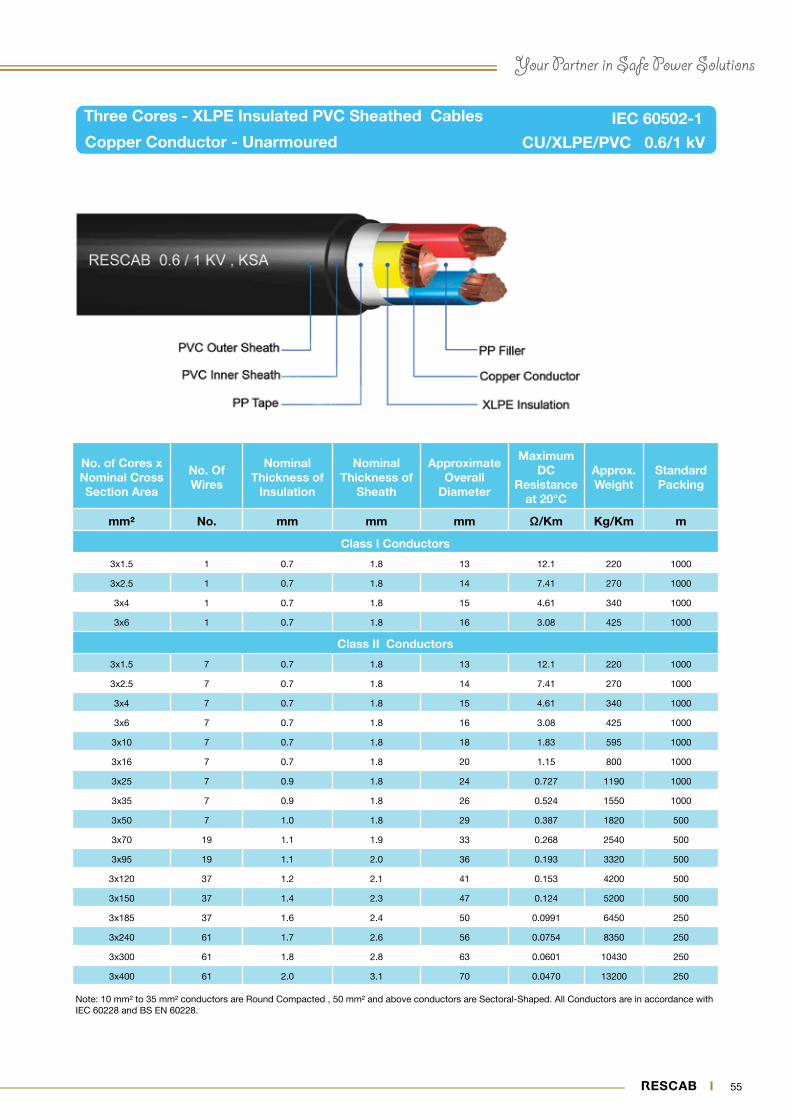
56 57
Four Cores - XLPE Insulated PVC Sheathed Cables
Copper Conductor - Unarmoured CU/XLPE/PVC 0.6/1 kV
IEC 60502-1
Note: 10 mm² to 35 mm² conductors are Round Compacted , 50 mm² and above conductors are Sectoral-Shaped. All Conductors are in accordance with IEC 60228 and BS EN 60228
No. of Cores x Nominal Cross Section Area
No. Of Wires
Nominal Thickness of
Insulation
Nominal Thickness of
Sheath
Approximate Overall
Diameter
Maximum DC
Resistance at 20°C
Approx. Weight
Standard Packing
mm² No. mm mm mm Ω/Km Kg/Km m
Class I Conductors
4x1.5 1 0.7 1.8 14 12.1 250 1000
4x2.5 1 0.7 1.8 15 7.41 310 1000
4x4 1 0.7 1.8 16 4.61 405 1000
4x6 1 0.7 1.8 18 3.08 510 1000
Class II Conductors
4x1.5 7 0.7 1.8 14 12.1 250 1000
4x2.5 7 0.7 1.8 15 7.41 310 1000
4x4 7 0.7 1.8 16 4.61 405 1000
4x6 7 0.7 1.8 18 3.08 510 1000
4x10 7 0.7 1.8 20 1.83 720 1000
4x16 7 0.7 1.8 22 1.15 985 1000
4x25 7 0.9 1.8 26 0.727 1460 1000
4x35 7 0.9 1.8 29 0.524 1830 1000
4x50 7 1.0 1.9 31 0.387 2250 500
4x70 19 1.1 2.0 36 0.268 3140 500
4x95 19 1.1 2.1 40 0.193 4200 500
4x120 37 1.2 2.3 44 0.153 5250 500
4x150 37 1.4 2.4 49 0.124 6460 500
4x185 37 1.6 2.6 53 0.0991 8010 250
4x240 61 1.7 2.8 59 0.0754 10320 250
4x300 61 1.8 3.0 65 0.0601 12780 250
4x400 61 2.0 3.3 74 0.0470 16330 250
56 57
Your Partner in Safe Power Solutions
Three & Half Cores - XLPE Insulated PVC Sheathed Cables
CU/XLPE/PVC 0.6/1 kV
IEC 60502-1
Note: Phase conductors 10 mm² to 35 mm² are Round Compacted, 50 mm² and above are Sectoral-Shaped. Neutral Conductors 10 mm² and above are Round Compacted. All Conductors are in accordance with IEC 60228 and BS EN 60228
Copper Conductor - Unarmoured
No of Cores x Nominal
Cross Section Area
No. Of WiresNominal
Thickness of Insulation
Nominal Thickness of Sheath
Approx. Overall
Diameter
Maximum DC Resistance at
20°CApprox. Weight
Standard Packing
Ph Ne Ph Ne Ph Ne
mm² No. No. mm mm mm mm Ω/Km Ω/Km Kg/Km m
Class II Conductors
3x10 + 6 7 7 0.7 0.7 1.8 20 1.83 3.08 670 1000
3x16 + 10 7 7 0.7 0.7 1.8 22 1.15 1.83 920 1000
3x25 + 16 7 7 0.9 0.7 1.8 26 0.727 1.15 1280 1000
3x35 + 16 7 7 0.9 0.7 1.8 27 0.524 1.15 1590 1000
3x50 + 25 7 7 1.0 0.9 1.8 30 0.387 0.727 2060 500
3x70 + 35 19 7 1.1 0.9 1.9 35 0.268 0.524 2890 500
3x95 + 50 19 7 1.1 1.0 2.1 39 0.193 0.387 3860 500
3x120 + 70 37 19 1.2 1.1 2.2 43 0.153 0.268 4770 500
3x150 + 70 37 19 1.4 1.1 2.3 47 0.124 0.268 5760 500
3x185 + 95 37 19 1.6 1.1 2.5 52 0.0991 0.193 7230 250
3x240 + 120 61 37 1.7 1.2 2.7 58 0.0754 0.153 9250 250
3x300 + 150 61 37 1.8 1.4 2.9 63 0.0601 0.124 11440 250
3x400 + 185 61 37 2.0 1.6 3.1 72 0.0470 0.0991 14480 250
58 59
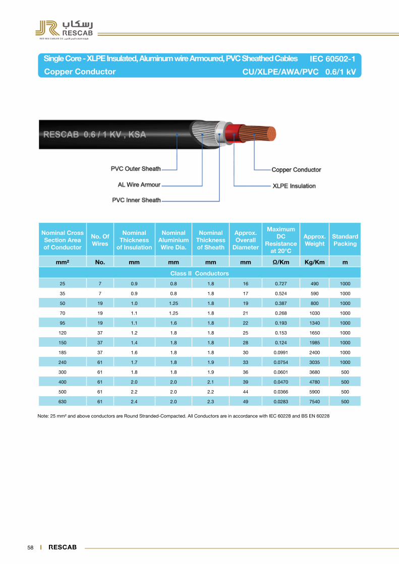
Single Core - XLPE Insulated, Aluminum wire Armoured, PVC Sheathed Cables
Copper Conductor CU/XLPE/AWA/PVC 0.6/1 kV
IEC 60502-1
Note: 25 mm² and above conductors are Round Stranded-Compacted. All Conductors are in accordance with IEC 60228 and BS EN 60228
Nominal Cross Section Area of Conductor
No. Of Wires
Nominal Thickness
of Insulation
Nominal Aluminium Wire Dia.
Nominal Thickness of Sheath
Approx. Overall
Diameter
Maximum DC
Resistance at 20°C
Approx. Weight
Standard Packing
mm² No. mm mm mm mm Ω/Km Kg/Km m
Class II Conductors
25 7 0.9 0.8 1.8 16 0.727 490 1000
35 7 0.9 0.8 1.8 17 0.524 590 1000
50 19 1.0 1.25 1.8 19 0.387 800 1000
70 19 1.1 1.25 1.8 21 0.268 1030 1000
95 19 1.1 1.6 1.8 22 0.193 1340 1000
120 37 1.2 1.8 1.8 25 0.153 1650 1000
150 37 1.4 1.8 1.8 28 0.124 1985 1000
185 37 1.6 1.8 1.8 30 0.0991 2400 1000
240 61 1.7 1.8 1.9 33 0.0754 3035 1000
300 61 1.8 1.8 1.9 36 0.0601 3680 500
400 61 2.0 2.0 2.1 39 0.0470 4780 500
500 61 2.2 2.0 2.2 44 0.0366 5900 500
630 61 2.4 2.0 2.3 49 0.0283 7540 500

58 59
Your Partner in Safe Power Solutions
Two Cores - XLPE Insulated, Steel Wire Armoured, PVC Sheathed Cables
Copper Conductor CU/XLPE/SWA/PVC 0.6/1 kV
IEC 60502-1
Note: 10 mm² and above conductors are Round Stranded-Compacted. All Conductors are in accordance with IEC 60228 and BS EN 60228
No. of Cores x Nominal Cross Section Area
No. Of Wires
Nominal Thickness
of Insulation
Nominal Steel Wire
Dia.
Nominal Thickness of Sheath
Approx. Overall
Diameter
Maximum DC
Resistance at 20°C
Approx. Weight
Standard Packing
mm² No. mm mm mm mm Ω/Km Kg/Km m
Class I Conductors
2x4 1 0.7 0.8 1.8 16 4.61 475 1000
2x6 1 0.7 0.8 1.8 17 3.08 550 1000
Class II Conductors
2x4 7 0.7 0.8 1.8 16 4.61 475 1000
2x6 7 0.7 0.8 1.8 17 3.08 550 1000
2x10 7 0.7 1.25 1.8 20 1.83 840 1000
2x16 7 0.7 1.25 1.8 22 1.15 1050 1000
2x25 7 0.9 1.6 1.8 26 0.727 1580 1000
2x35 7 0.9 1.6 1.8 28 0.524 1925 1000

60 61
Three Cores - XLPE Insulated, Steel Wire Armoured, PVC Sheathed Cables
Copper Conductor CU/XLPE/SWA/PVC 0.6/1 kV
IEC 60502-1
Note: 10 mm² to 35 mm² conductors are Round Compacted , 50 mm² and above conductors are Sectoral-Shaped. All Conductors are in accordance with IEC 60228 and BS EN 60228.
No. of Cores x Nominal Cross Section Area
No. Of Wires
Nominal Thickness
of Insulation
Nominal Steel
Wire Dia.
Nominal Thickness of Sheath
Approx. Overall
Diameter
Maximum DC
Resistance at 20°C
Approx. Weight
Standard Packing
mm² No. mm mm mm mm Ω/Km Kg/Km m
Class I Conductors
3x4 1 0.7 0.8 1.8 17 4.61 550 1000
3x6 1 0.7 0.8 1.8 18 3.08 665 1000
Class II Conductors
3x4 7 0.7 0.8 1.8 17 4.61 550 1000
3x6 7 0.7 1.25 1.8 18 3.08 665 1000
3x10 7 0.7 1.25 1.8 21 1.83 980 1000
3x16 7 0.7 1.25 1.8 23 1.15 1250 1000
3x25 7 0.9 1.6 1.8 27 0.727 1890 1000
3x35 7 0.9 1.6 1.8 29 0.524 2390 1000
3x50 7 1.0 1.6 1.9 32 0.387 2680 500
3x70 19 1.1 2.0 2.0 37 0.268 3835 500
3x95 19 1.1 2.0 2.2 40 0.193 4760 500
3x120 37 1.2 2.0 2.3 45 0.153 5825 500
3x150 37 1.4 2.5 2.5 53 0.124 7430 500
3x185 37 1.6 2.5 2.6 55 0.0991 8930 250
3x240 61 1.7 2.5 2.8 62 0.0754 11200 250
3x300 61 1.8 2.5 3.0 68 0.0601 13550 250
3x400 61 2.0 2.5 3.2 75 0.0470 16610 250

60 61
Your Partner in Safe Power Solutions
Four Cores - XLPE Insulated, Steel Wire Armoured, PVC Sheathed Cables
Copper Conductor CU/XLPE/SWA/PVC 0.6/1 kV
IEC 60502-1
Note: 10 mm² to 35 mm² conductors are Round Compacted , 50 mm² and above conductors are Sectoral-Shaped. All Conductors are in accordance with IEC 60228 and BS EN 60228
No. of Cores x Nominal Cross Section Area
No. Of Wires
Nominal Thickness
of Insulation
Nominal Steel
Wire Dia.
Nominal Thickness of Sheath
Approx. Overall
Diameter
Maximum DC
Resistance at 20°C
Approx. Weight
Standard Packing
mm² No. mm mm mm mm Ω/Km Kg/Km m
Class I Conductors
4x4 1 0.7 0.8 1.8 18 4.61 600 1000
4x6 1 0.7 1.25 1.8 20 3.08 850 1000
Class II Conductors
4x4 7 0.7 1.25 1.8 18 4.61 600 1000
4x6 7 0.7 1.25 1.8 20 3.08 850 1000
4x10 7 0.7 1.25 1.8 22 1.83 1150 1000
4x16 7 0.7 1.6 1.8 25 1.15 1590 1000
4x25 7 0.9 1.6 1.8 30 0.727 2125 1000
4x35 7 0.9 1.6 1.9 32 0.524 2635 1000
4x50 7 1.0 1.6 2.0 35 0.387 3100 500
4x70 19 1.1 2.0 2.2 40 0.268 4440 500
4x95 19 1.1 2.0 2.3 43 0.193 5630 500
4x120 37 1.2 2.5 2.5 49 0.153 7260 500
4x150 37 1.4 2.5 2.6 54 0.124 8680 500
4x185 37 1.6 2.5 2.8 59 0.0991 10455 250
4x240 61 1.7 2.5 3.0 65 0.0754 13170 250
4x300 61 1.8 2.50 3.2 70 0.0601 15920 250
4x400 61 2.0 3.15 3.5 80 0.0470 20830 250
62 63
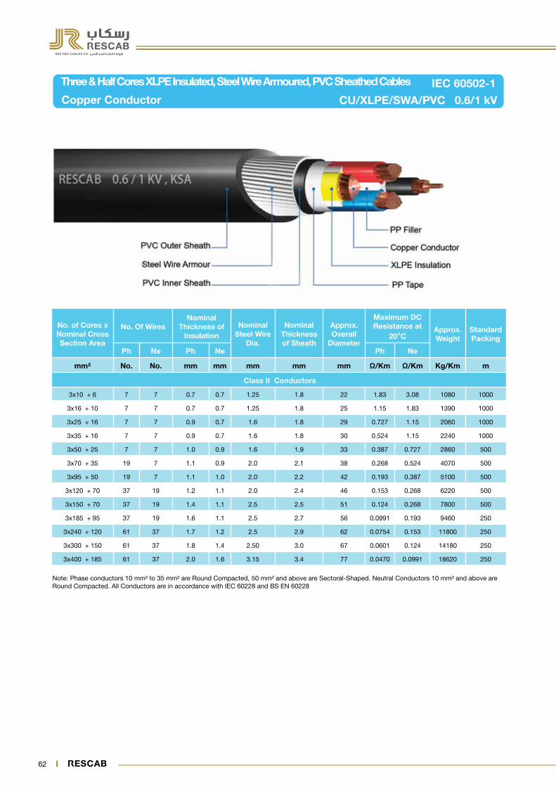
Three & Half Cores XLPE Insulated, Steel Wire Armoured, PVC Sheathed Cables
Copper Conductor CU/XLPE/SWA/PVC 0.6/1 kV
IEC 60502-1
Note: Phase conductors 10 mm² to 35 mm² are Round Compacted, 50 mm² and above are Sectoral-Shaped. Neutral Conductors 10 mm² and above are Round Compacted. All Conductors are in accordance with IEC 60228 and BS EN 60228
No. of Cores x Nominal Cross Section Area
No. Of WiresNominal
Thickness of Insulation
Nominal Steel Wire
Dia.
Nominal Thickness of Sheath
Approx. Overall
Diameter
Maximum DC Resistance at
20°CApprox. Weight
Standard Packing
Ph Ne Ph Ne Ph Ne
mm² No. No. mm mm mm mm mm Ω/Km Ω/Km Kg/Km m
Class II Conductors
3x10 + 6 7 7 0.7 0.7 1.25 1.8 22 1.83 3.08 1080 1000
3x16 + 10 7 7 0.7 0.7 1.25 1.8 25 1.15 1.83 1390 1000
3x25 + 16 7 7 0.9 0.7 1.6 1.8 29 0.727 1.15 2060 1000
3x35 + 16 7 7 0.9 0.7 1.6 1.8 30 0.524 1.15 2240 1000
3x50 + 25 7 7 1.0 0.9 1.6 1.9 33 0.387 0.727 2860 500
3x70 + 35 19 7 1.1 0.9 2.0 2.1 38 0.268 0.524 4070 500
3x95 + 50 19 7 1.1 1.0 2.0 2.2 42 0.193 0.387 5100 500
3x120 + 70 37 19 1.2 1.1 2.0 2.4 46 0.153 0.268 6220 500
3x150 + 70 37 19 1.4 1.1 2.5 2.5 51 0.124 0.268 7800 500
3x185 + 95 37 19 1.6 1.1 2.5 2.7 56 0.0991 0.193 9460 250
3x240 + 120 61 37 1.7 1.2 2.5 2.9 62 0.0754 0.153 11800 250
3x300 + 150 61 37 1.8 1.4 2.50 3.0 67 0.0601 0.124 14180 250
3x400 + 185 61 37 2.0 1.6 3.15 3.4 77 0.0470 0.0991 18620 250

62 63
Your Partner in Safe Power Solutions
Single Core - XLPE Insulated, Aluminum Tape Armoured, PVC Sheathed Cables
Copper Conductor CU/XLPE/ATA/PVC 0.6/1 kV
IEC 60502-1
Note: 25 mm² and above conductors are Round Stranded-Compacted. All Conductors are in accordance with IEC 60228 and BS EN 60228
Nominal Cross Section
Area of Conductor
No. Of Wires
Nominal Thickness
of Insulation
Nominal Aluminium
Tape Thickness
Nominal Thickness of Sheath
Approx. Overall
Diameter
Maximum DC
Resistance at 20°C
Approx. Weight
Standard Packing
mm² No. mm mm mm mm Ω/Km Kg/Km m
Class II Conductors
25 7 0.9 0.5 1.8 16 0.727 490 1000
35 7 0.9 0.5 1.8 17 0.524 590 1000
50 19 1.0 0.5 1.8 19 0.387 775 1000
70 19 1.1 0.5 1.8 21 0.268 1005 1000
95 19 1.1 0.5 1.8 22 0.193 1290 1000
120 37 1.2 0.5 1.8 24 0.153 1530 1000
150 37 1.4 0.5 1.8 27 0.124 1840 1000
185 37 1.6 0.5 1.8 29 0.0991 2220 1000
240 61 1.7 0.5 1.8 32 0.0754 2830 1000
300 61 1.8 0.5 1.9 35 0.0601 3500 500
400 61 2.0 0.5 2.0 37 0.0470 4415 500
500 61 2.2 0.5 2.1 42 0.0366 5560 500
630 61 2.4 0.5 2.3 47 0.0283 7090 500

64 65
Two Cores - XLPE Insulated, Steel Tape Armoured, PVC Sheathed Cables
Copper Conductor CU/XLPE/STA/PVC 0.6/1 kV
IEC 60502-1
Note: 10 mm² and above conductors are Round Stranded-Compacted. All Conductors are in accordance with IEC 60228 and BS EN 60228
No. of Cores x Nominal
Cross Section Area
No. Of Wires
Nominal Thickness
of Insulation
Nominal Steel Tape Thickness
Nominal Thickness of Sheath
Approx. Overall
Diameter
Maximum DC
Resistance at 20°C
Approx. Weight
Standard Packing
mm² No. mm mm mm mm Ω/Km Kg/Km m
Class I Conductors
2x4 1 0.7 0.2 1.8 15 4.61 390 1000
2x6 1 0.7 0.2 1.8 16 3.08 470 1000
Class II Conductors
2x4 7 0.7 0.2 1.8 15 4.61 390 1000
2x6 7 0.7 0.2 1.8 16 3.08 470 1000
2x10 7 0.7 0.2 1.8 18 1.83 600 1000
2x16 7 0.7 0.2 1.8 20 1.15 790 1000
2x25 7 0.9 0.2 1.8 24 0.727 1130 1000
2x35 7 0.9 0.2 1.8 26 0.524 1420 1000

64 65
Your Partner in Safe Power Solutions
Three Cores - XLPE Insulated, Steel Tape Armoured, PVC Sheathed Cables
Copper Conductor CU/XLPE/STA/PVC 0.6/1 kV
IEC 60502-1
Note: 10 mm² to 35 mm² conductors are Round Compacted , 50 mm² and above conductors are Sectoral-Shaped. All Conductors are in accordance with IEC 60228 and BS EN 60228.
No. of Cores x Nominal
Cross Section Area
No. Of Wires
Nominal Thickness
of Insulation
Nominal Steel Tape Thickness
Nominal Thickness of Sheath
Approx. Overall
Diameter
Maximum DC
Resistance at 20°C
Approx. Weight
Standard Packing
mm² No. mm mm mm mm Ω/Km Kg/Km m
Class I Conductors
3x4 1 0.7 0.2 1.8 16 4.61 430 1000
3x6 1 0.7 0.2 1.8 16 3.08 475 1000
Class II Conductors
3x4 7 0.7 0.2 1.8 16 4.61 430 1000
3x6 7 0.7 0.2 1.8 17 3.08 525 1000
3x10 7 0.7 0.2 1.8 19 1.83 710 1000
3x16 7 0.7 0.2 1.8 21 1.15 950 1000
3x25 7 0.9 0.2 1.8 25 0.727 1370 1000
3x35 7 0.9 0.2 1.8 27 0.524 1600 1000
3x50 7 1.0 0.2 1.8 31 0.387 2075 500
3x70 19 1.1 0.2 2.0 35 0.268 2860 500
3x95 19 1.1 0.5 2.1 39 0.193 3750 500
3x120 37 1.2 0.5 2.3 45 0.153 5070 500
3x150 37 1.4 0.5 2.4 50 0.124 6140 500
3x185 37 1.6 0.5 2.6 55 0.0991 7470 250
3x240 61 1.7 0.5 2.7 62 0.0754 9500 250
3x300 61 1.8 0.5 2.9 68 0.0601 11600 250
3x400 61 2.0 0.5 3.2 75 0.0470 14650 250

66 67
Four Cores - XLPE Insulated, Steel Tape Armoured, PVC Sheathed Cables
Copper Conductor CU/XLPE/STA/PVC 0.6/1 kV
IEC 60502-1
Note: 10 mm² to 35 mm² conductors are Round Compacted , 50 mm² and above conductors are Sectoral-Shaped. All Conductors are in accordance with IEC 60228 and BS EN 60228
No. of Cores x Nominal
Cross Section Area
No. Of Wires
Nominal Thickness
of Insulation
Nominal Steel Tape Thickness.
Nominal Thickness of Sheath
Approx. Overall
Diameter
Maximum DC
Resistance at 20°C
Approx. Weight
Standard Packing
mm² No. mm mm mm mm Ω/Km Kg/Km m
Class I Conductors
4x4 1 0.7 0.2 1.8 17 4.61 500 1000
4x6 1 0.7 0.2 1.8 18 3.08 630 1000
Class II Conductors
4x4 7 0.7 0.2 1.8 17 4.61 500 1000
4x6 7 0.7 0.2 1.8 18 3.08 630 1000
4x10 7 0.7 0.2 1.8 20 1.83 840 1000
4x16 7 0.7 0.2 1.8 23 1.15 1160 1000
4x25 7 0.9 0.2 1.8 27 0.727 1680 1000
4x35 7 0.9 0.2 1.8 28 0.524 1890 1000
4x50 7 1.0 0.2 1.9 32 0.387 2470 500
4x70 19 1.1 0.5 2.1 38 0.268 3400 500
4x95 19 1.1 0.5 2.3 42 0.193 4910 500
4x120 37 1.2 0.5 2.4 46 0.153 6030 500
4x150 37 1.4 0.5 2.6 51 0.124 7330 500
4x185 37 1.6 0.5 2.7 55 0.0991 8900 250
4x240 61 1.7 0.5 2.9 62 0.0754 11400 250
4x300 61 1.8 0.5 3.1 67 0.0601 14000 250
4x400 61 2.0 0.5 3.4 76 0.0470 17760 250

66 67
Your Partner in Safe Power Solutions
Three & Half Cores XLPE Insulated, Steel Tape Armoured, PVC Sheathed Cables
Copper Conductor CU/XLPE/STA/PVC 0.6/1 kV
IEC 60502-1
Note: Phase conductors 10 mm² to 35 mm² are Round Compacted, 50 mm² and above are Sectoral-Shaped. Neutral Conductors 10 mm² and above are Round Compacted. All Conductors are in accordance with IEC 60228 and BS EN 60228
No. of Cores x Nominal Cross Section Area
No. Of WiresNominal
Thickness of Insulation
Nominal Steel Tape Thickness
Nominal Thickness of Sheath
Approx. Overall
Diameter
Maximum DC Resistance at
20°CApprox. Weight
Standard Packing
Ph Ne Ph Ne Ph Ne
mm² No. No. mm mm mm mm mm Ω/Km Ω/Km Kg/Km m
Class II Conductors
3x10 + 6 7 7 0.7 0.7 0.2 1.8 20 1.83 3.08 780 1000
3x16 + 10 7 7 0.7 0.7 0.2 1.8 23 1.15 1.83 1060 1000
3x25 + 16 7 7 0.9 0.7 0.2 1.8 26 0.727 1.15 1535 1000
3x35 + 16 7 7 0.9 0.7 0.2 1.8 27 0.524 1.15 1690 1000
3x50 + 25 7 7 1.0 0.9 0.2 1.9 30 0.387 0.727 2235 500
3x70 + 35 19 7 1.1 0.9 0.2 2.0 34 0.268 0.524 3070 500
3x95 + 50 19 7 1.1 1.0 0.5 2.2 40 0.193 0.387 4330 500
3x120 + 70 37 19 1.2 1.1 0.5 2.3 44 0.153 0.268 5350 500
3x150 + 70 37 19 1.4 1.1 0.5 2.5 48 0.124 0.268 6400 500
3x185 + 95 37 19 1.6 1.1 0.5 2.6 53 0.0991 0.193 7900 250
3x240 + 120 61 37 1.7 1.2 0.5 2.8 59 0.0754 0.153 11000 250
3x300 + 150 61 37 1.8 1.4 0.5 3.0 64 0.0601 0.124 12370 250
3x400 + 185 61 37 2.0 1.6 0.5 3.3 72 0.0470 0.0991 15550 250

68 69
Note: 16 mm² and above conductors are Round Stranded-Compacted. All Conductors are in accordance with IEC 60228 and BS EN 60228
Single Core - PVC Insulated PVC Sheathed Cables
Aluminium Conductor - Unarmoured AL/PVC/PVC 0.6/1 kV
IEC 60502-1
Nominal Cross Section Area of Conductor
No. Of Wires
Nominal Thickness of
Insulation
Nominal Thickness of Sheath
Approximate Overall
Diameter
Maximum DC Resistance at
20 C
Approx. Weight
Standard Packing
mm² No. mm mm mm Ω/Km Kg/Km m
Class II Conductors
16 7 1.0 1.4 10 1.91 138 2000
25 7 1.2 1.4 12 1.20 188 1000
35 7 1.2 1.4 13 0.868 227 1000
50 7 1.4 1.4 15 0.641 310 1000
70 19 1.4 1.4 16 0.443 380 1000
95 19 1.6 1.5 18 0.320 510 1000
120 19 1.6 1.5 20 0.253 605 1000
150 19 1.8 1.6 22 0.206 735 1000
185 37 2.0 1.7 25 0.164 910 1000
240 37 2.2 1.8 28 0.125 1160 1000
300 37 2.4 1.9 31 0.100 1410 1000
400 61 2.6 2.0 34 0.778 1750 500
500 61 2.8 2.1 39 0.0605 2210 500
630 61 2.8 2.2 43 0.0469 2725 500

68 69
Your Partner in Safe Power Solutions
Note: 16 mm² and above conductors are Round Stranded-Compacted. All Conductors are in accordance with IEC 60228 and BS EN 60228
Two Cores - PVC Insulated PVC Sheathed Cables
Aluminium Conductor - Unarmoured AL/PVC/PVC 0.6/1 kV
IEC 60502-1
No. of Cores x Nominal Cross Section Area
No. Of Wires
Nominal Thickness of
Insulation
Nominal Thickness of Sheath
Approximate Overall
Diameter
Maximum DC Resistance at
20°C
Approx. Weight
Standard Packing
mm² No. mm mm mm Ω/Km Kg/Km m
Class II Conductors
2x16 7 1.0 1.8 20 1.91 530 1000
2x25 7 1.2 1.8 24 1.20 730 1000
2x35 7 1.2 1.8 26 0.868 870 1000
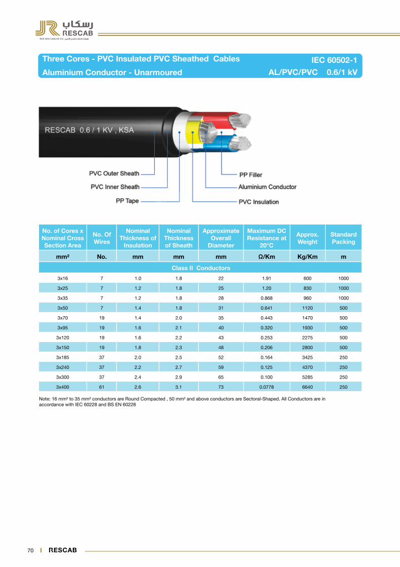
70 71
Note: 16 mm² to 35 mm² conductors are Round Compacted , 50 mm² and above conductors are Sectoral-Shaped. All Conductors are in accordance with IEC 60228 and BS EN 60228
Three Cores - PVC Insulated PVC Sheathed Cables
Aluminium Conductor - Unarmoured AL/PVC/PVC 0.6/1 kV
IEC 60502-1
No. of Cores x Nominal Cross Section Area
No. Of Wires
Nominal Thickness of
Insulation
Nominal Thickness of Sheath
Approximate Overall
Diameter
Maximum DC Resistance at
20°C
Approx. Weight
Standard Packing
mm² No. mm mm mm Ω/Km Kg/Km m
Class II Conductors
3x16 7 1.0 1.8 22 1.91 600 1000
3x25 7 1.2 1.8 25 1.20 830 1000
3x35 7 1.2 1.8 28 0.868 960 1000
3x50 7 1.4 1.8 31 0.641 1120 500
3x70 19 1.4 2.0 35 0.443 1470 500
3x95 19 1.6 2.1 40 0.320 1930 500
3x120 19 1.6 2.2 43 0.253 2275 500
3x150 19 1.8 2.3 48 0.206 2800 500
3x185 37 2.0 2.5 52 0.164 3425 250
3x240 37 2.2 2.7 59 0.125 4370 250
3x300 37 2.4 2.9 65 0.100 5285 250
3x400 61 2.6 3.1 73 0.0778 6640 250

70 71
Your Partner in Safe Power Solutions
Note 16 mm² to 35 mm² conductors are Round Compacted , 50 mm² and above conductors are Sectoral-Shaped. All Conductors are in accordance with IEC 60228 and BS EN 60228
Four Cores - PVC Insulated PVC Sheathed Cables
Aluminium Conductor - Unarmoured AL/PVC/PVC 0.6/1 kV
IEC 60502-1
No. of Cores x Nominal Cross Section Area
No. Of Wires
Nominal Thickness of
Insulation
Nominal Thickness of Sheath
Approximate Overall
Diameter
Maximum DC Resistance at
20°C
Approx. Weight
Standard Packing
mm² No. mm mm mm Ω/Km Kg/Km m
Class II Conductors
4x16 7 1.0 1.8 23 1.91 695 1000
4x25 7 1.2 1.8 28 1.20 940 1000
4x35 7 1.2 1.8 30 0.868 990 1000
4x50 7 1.4 1.9 33 0.641 1290 500
4x70 19 1.4 2.1 37 0.443 1660 500
4x95 19 1.6 2.2 42 0.320 2160 500
4x120 37 1.6 2.4 46 0.253 2610 500
4x150 37 1.8 2.5 50 0.206 3170 500
4x185 37 2.0 2.7 56 0.164 3910 250
4x240 37 2.2 2.9 62 0.125 4980 250
4x300 37 2.4 3.1 68 0.100 6055 250
4x400 61 2.6 3.4 77 0.0778 7695 250

72 73
Note: Phase conductors 25 mm² and 35 mm² are Round Compacted, 50 mm² and above are Sectoral-Shaped. Neutral Conductors 16 mm² and above are Round Compacted. All Conductors are in accordance with IEC 60228 and BS EN 60228
Three & Half Cores - PVC Insulated PVC Sheathed Cables
Aluminium Conductor - Unarmoured AL/PVC/PVC 0.6/1 kV
IEC 60502-1
No of Cores x Nominal
Cross Section Area
No. Of WiresNominal
Thickness of Insulation
Nominal Thickness of Sheath
Approx. Overall
Diameter
Maximum DC Resistance at
20°CApprox. Weight
Standard Packing
Ph Ne Ph Ne Ph Ne
mm² No. No. mm mm mm mm Ω/Km Ω/Km Kg/Km m
Class II Conductors
3x25 + 16 7 7 1.2 1.0 1.8 27 1.20 1.91 860 1000
3x35 + 16 7 7 1.2 1.0 1.8 29 0.868 1.91 925 1000
3x50 + 25 7 7 1.4 1.2 1.9 32 0.641 1.20 1180 500
3x70 + 35 19 7 1.4 1.2 2.0 36 0.443 0.868 1510 500
3x95 + 50 19 7 1.6 1.4 2.2 40 0.320 0.641 1990 500
3x120 + 70 37 19 1.6 1.4 2.3 44 0.253 0.443 2425 500
3x150 + 70 37 19 1.8 1.4 2.4 48 0.206 0.443 2860 500
3x185 + 95 37 19 2.0 1.6 2.6 53 0.164 0.320 3525 250
3x240 + 120 37 37 2.2 1.6 2.8 59 0.125 0.253 4495 250
3x300 + 150 37 37 2.4 1.8 3.0 65 0.100 0.206 5484 250
3x400 + 185 61 37 2.6 2.0 3.2 74 0.0778 0.164 6885 250

72 73
Your Partner in Safe Power Solutions
Note: 16 mm² and above conductors are Round Stranded-Compacted. All Conductors are in accordance with IEC 60228 and BS EN 60228
Single Core - PVC Insulated, AL Wire Armoured PVC Sheathed Cables
Aluminium Conductor AL/PVC/AWA/PVC 0.6/1 kV
IEC 60502-1
Nominal Cross Section
Area of Conductor
No. Of Wires
Nominal Thickness
of Insulation
Nominal Aluminium Wire Dia.
Nominal Thickness of Sheath
Approx. Overall
Diameter
Maximum DC
Resistance at 20°C
Approx. Weight
Standard Packing
mm² No. mm mm mm mm Ω/Km Kg/Km m
Class II Conductors
16 7 1.0 0.8 1.8 15 1.91 280 2000
25 7 1.2 0.8 1.8 16 1.20 360 1000
35 7 1.2 0.8 1.8 18 0.868 410 1000
50 7 1.4 1.25 1.8 20 0.641 570 1000
70 19 1.4 1.25 1.8 22 0.443 690 1000
95 19 1.6 1.6 1.8 24 0.320 845 1000
120 19 1.6 1.6 1.8 26 0.253 1025 1000
150 19 1.8 1.6 1.8 28 0.206 1185 1000
185 37 2.0 1.6 1.8 32 0.164 1385 1000
240 37 2.2 1.6 1.9 34 0.125 1670 1000
300 37 2.4 2.0 2.0 37 0.100 2100 500
400 61 2.6 2.0 2.1 41 0.0778 2560 500
500 61 2.8 2.0 2.2 45 0.0605 3130 500
630 61 2.8 2.0 2.4 51 0.0469 3735 500
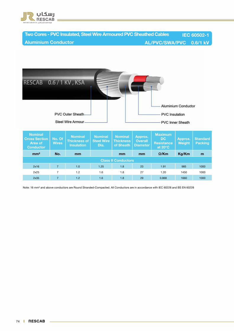
74 75
Note: 16 mm² and above conductors are Round Stranded-Compacted. All Conductors are in accordance with IEC 60228 and BS EN 60228
Two Cores - PVC Insulated, Steel Wire Armoured PVC Sheathed Cables
Aluminium Conductor AL/PVC/SWA/PVC 0.6/1 kV
IEC 60502-1
Nominal Cross Section
Area of Conductor
No. Of Wires
Nominal Thickness of
Insulation
Nominal Steel Wire
Dia.
Nominal Thickness of Sheath
Approx. Overall
Diameter
Maximum DC
Resistance at 20°C
Approx. Weight
Standard Packing
mm² No. mm mm mm Ω/Km Kg/Km m
Class II Conductors
2x16 7 1.0 1.25 1.8 23 1.91 985 1000
2x25 7 1.2 1.6 1.8 27 1.20 1450 1000
2x35 7 1.2 1.6 1.8 29 0.868 1660 1000

74 75
Your Partner in Safe Power Solutions
Note: 10 mm² to 35 mm² conductors are Round Compacted , 50 mm² and above conductors are Sectoral-Shaped. All Conductors are in accordance with IEC 60228 and BS EN 60228.
Three Cores - PVC Insulated, Steel Wire Armoured, PVC Sheathed Cables
Aluminium Conductor AL/PVC/SWA/PVC 0.6/1 kV
IEC 60502-1
No of Cores x Nominal
Cross Section Area
No. Of Wires
Nominal Thickness
of Insulation
Nominal Steel Wire
Dia.
Nominal Thickness of Sheath
Approx. Overall
Diameter
Maximum DC
Resistance at 20°C
Approx. Weight
Standard Packing
mm² No. mm mm mm mm Ω/Km Kg/Km m
Class II Conductors
3x16 7 1.0 1.25 1.8 24 1.91 1060 1000
3x25 7 1.2 1.6 1.8 29 1.20 1540 1000
3x35 7 1.2 1.6 1.8 31 0.868 1800 1000
3x50 7 1.4 1.6 2.0 35 0.641 2050 500
3x70 19 1.4 2.0 2.1 39 0.443 2820 500
3x95 19 1.6 2.0 2.2 45 0.320 3470 500
3x120 19 1.6 2.0 2.3 48 0.253 3915 500
3x150 19 1.8 2.5 2.5 55 0.206 5125 500
3x185 37 2.0 2.5 2.7 58 0.164 6040 250
3x240 37 2.2 2.5 2.9 65 0.125 7290 250
3x300 37 2.4 2.5 3.1 72 0.100 8580 250
3x400 61 2.6 3.15 3.4 82 0.0778 11395 250

76 77
Note: 16 mm² to 35 mm² conductors are Round Compacted , 50 mm² and above conductors are Sectoral-Shaped. All Conductors are in accordance with IEC 60228 and BS EN 60228
Four Core - PVC Insulated, Steel Wire Armoured, PVC Sheathed Cables
Aluminium Conductor AL/PVC/SWA/PVC 0.6/1 kV
IEC 60502-1
No of Cores x Nominal
Cross Section Area
No. Of Wires
Nominal Thickness
of Insulation
Nominal Steel Wire
Dia.
Nominal Thickness of Sheath
Approx. Overall
Diameter
Maximum DC
Resistance at 20°C
Approx. Weight
Standard Packing
mm² No. mm mm mm mm Ω/Km Kg/Km m
Class II Conductors
4x16 7 1.0 1.6 1.8 26 1.91 1340 1000
4x25 7 1.2 1.6 1.8 31 1.20 1650 1000
4x35 7 1.2 1.6 1.9 33 0.868 1870 1000
4x50 7 1.4 2.0 2.1 38 0.641 2535 500
4x70 19 1.4 2.0 2.2 42 0.443 3010 500
4x95 19 1.6 2.5 2.4 48 0.320 4140 500
4x120 37 1.6 2.5 2.5 52 0.253 4710 500
4x150 37 1.8 2.5 2.7 57 0.206 5490 500
4x185 37 2.0 2.5 2.9 62 0.164 6490 250
4x240 37 2.2 2.5 3.1 68 0.125 7890 250
4x300 37 2.4 2.5 3.3 76 0.100 9340 250
4x400 61 2.6 3.15 3.6 85 0.0778 12180 250
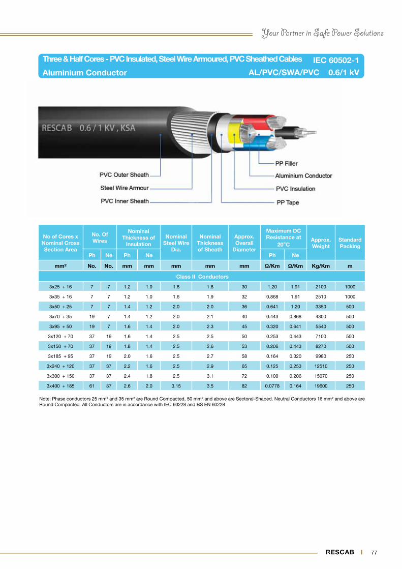
76 77
Your Partner in Safe Power Solutions
Note: Phase conductors 25 mm² and 35 mm² are Round Compacted, 50 mm² and above are Sectoral-Shaped. Neutral Conductors 16 mm² and above are Round Compacted. All Conductors are in accordance with IEC 60228 and BS EN 60228
Three & Half Cores - PVC Insulated, Steel Wire Armoured, PVC Sheathed Cables
Aluminium Conductor AL/PVC/SWA/PVC 0.6/1 kV
IEC 60502-1
No of Cores x Nominal Cross Section Area
No. Of Wires
Nominal Thickness of
InsulationNominal
Steel Wire Dia.
Nominal Thickness of Sheath
Approx. Overall
Diameter
Maximum DC Resistance at
20°CApprox. Weight
Standard Packing
Ph Ne Ph Ne Ph Ne
mm² No. No. mm mm mm mm mm Ω/Km Ω/Km Kg/Km m
Class II Conductors
3x25 + 16 7 7 1.2 1.0 1.6 1.8 30 1.20 1.91 2100 1000
3x35 + 16 7 7 1.2 1.0 1.6 1.9 32 0.868 1.91 2510 1000
3x50 + 25 7 7 1.4 1.2 2.0 2.0 36 0.641 1.20 3350 500
3x70 + 35 19 7 1.4 1.2 2.0 2.1 40 0.443 0.868 4300 500
3x95 + 50 19 7 1.6 1.4 2.0 2.3 45 0.320 0.641 5540 500
3x120 + 70 37 19 1.6 1.4 2.5 2.5 50 0.253 0.443 7100 500
3x150 + 70 37 19 1.8 1.4 2.5 2.6 53 0.206 0.443 8270 500
3x185 + 95 37 19 2.0 1.6 2.5 2.7 58 0.164 0.320 9980 250
3x240 + 120 37 37 2.2 1.6 2.5 2.9 65 0.125 0.253 12510 250
3x300 + 150 37 37 2.4 1.8 2.5 3.1 72 0.100 0.206 15070 250
3x400 + 185 61 37 2.6 2.0 3.15 3.5 82 0.0778 0.164 19600 250
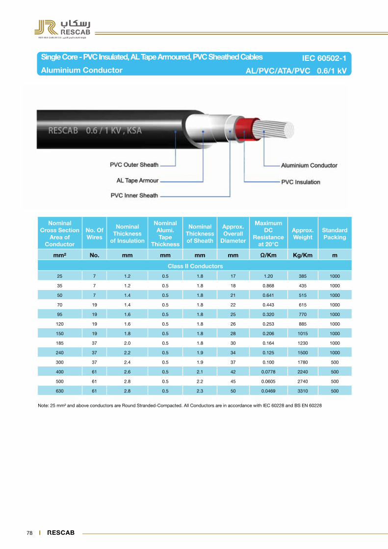
78 79
Note: 25 mm² and above conductors are Round Stranded-Compacted. All Conductors are in accordance with IEC 60228 and BS EN 60228
Single Core - PVC Insulated, AL Tape Armoured, PVC Sheathed Cables
Aluminium Conductor AL/PVC/ATA/PVC 0.6/1 kV
IEC 60502-1
Nominal Cross Section
Area of Conductor
No. Of Wires
Nominal Thickness
of Insulation
Nominal Alumi. Tape
Thickness
Nominal Thickness of Sheath
Approx. Overall
Diameter
Maximum DC
Resistance at 20°C
Approx. Weight
Standard Packing
mm² No. mm mm mm mm Ω/Km Kg/Km m
Class II Conductors
25 7 1.2 0.5 1.8 17 1.20 385 1000
35 7 1.2 0.5 1.8 18 0.868 435 1000
50 7 1.4 0.5 1.8 21 0.641 515 1000
70 19 1.4 0.5 1.8 22 0.443 615 1000
95 19 1.6 0.5 1.8 25 0.320 770 1000
120 19 1.6 0.5 1.8 26 0.253 885 1000
150 19 1.8 0.5 1.8 28 0.206 1015 1000
185 37 2.0 0.5 1.8 30 0.164 1230 1000
240 37 2.2 0.5 1.9 34 0.125 1500 1000
300 37 2.4 0.5 1.9 37 0.100 1780 500
400 61 2.6 0.5 2.1 42 0.0778 2240 500
500 61 2.8 0.5 2.2 45 0.0605 2740 500
630 61 2.8 0.5 2.3 50 0.0469 3310 500

78 79
Your Partner in Safe Power Solutions
Note: 16 mm² and above conductors are Round Stranded-Compacted. All Conductors are in accordance with IEC 60228 and BS EN 60228
Two Cores - PVC Insulated, Steel Tape Armoured, PVC Sheathed Cables
Aluminium Conductor AL/PVC/STA/PVC 0.6/1 kV
IEC 60502-1
Nominal Cross Section
Area of Conductor
No. Of Wires
Nominal Thickness
of Insulation
Nominal Steel Tape Thickness
Nominal Thickness of Sheath
Approx. Overall
Diameter
Maximum DC
Resistance at 20° C
Approx. Weight
Standard Packing
mm² No. mm mm mm mm Ω/Km Kg/Km m
Class II Conductors
2x16 7 1.0 0.2 1.8 21 1.91 670 1000
2x25 7 1.2 0.2 1.8 25 1.20 815 1000
2x35 7 1.2 0.2 1.8 27 0.868 980 1000

80 81
Note: 16 mm² to 35 mm² conductors are Round Compacted , 50 mm² and above conductors are Sectoral-Shaped. All Conductors are in accordance with IEC 60228 and BS EN 60228
Three Cores - PVC Insulated, Steel Tape Armoured, PVC Sheathed Cables
Aluminium Conductor AL/PVC/STA/PVC 0.6/1 kV
IEC 60502-1
No of Cores x Nominal
Cross Section Area
No. Of Wires
Nominal Thickness
of Insulation
Nominal Steel Tape Thickness
Nominal Thickness of Sheath
Approx. Overall
Diameter
Maximum DC
Resistance at 20°C
Approx. Weight
Standard Packing
mm² No. mm mm mm mm Ω/Km Kg/Km m
Class II Conductors
3x16 7 1.0 0.2 1.8 23 1.91 710 1000
3x25 7 1.2 0.2 1.8 26 1.20 980 1000
3x35 7 1.2 0.2 1.8 29 0.868 1120 1000
3x50 7 1.4 0.2 1.9 32 0.641 1325 500
3x70 19 1.4 0.2 2.0 36 0.443 1700 500
3x95 19 1.6 0.5 2.2 42 0.320 2580 500
3x120 19 1.6 0.5 2.3 45 0.253 3000 500
3x150 19 1.8 0.5 2.5 52 0.206 3630 500
3x185 37 2.0 0.5 2.6 54 0.164 4300 250
3x240 37 2.2 0.5 2.8 61 0.125 5350 250
3x300 37 2.4 0.5 3.0 67 0.100 6375 250
3x400 61 2.6 0.5 3.3 75 0.0778 7910 250

80 81
Your Partner in Safe Power Solutions
Note: 16 mm² to 35 mm² conductors are Round Compacted , 50 mm² and above conductors are Sectoral-Shaped. All Conductors are in accordance with IEC 60228 and BS EN 60228
Four Cores - PVC Insulated, Steel Tape Armoured, PVC Sheathed Cables
Aluminium Conductor AL/PVC/STA/PVC 0.6/1 kV
IEC 60502-1
No. of Cores x Nominal
Cross Section Area
No. Of Wires
Nominal Thickness
of Insulation
Nominal Steel Tape Thickness
Nominal Thickness of Sheath
Approx. Overall
Diameter
Maximum DC
Resistance at 20 C
Approx. Weight
Standard Packing
mm² No. mm mm mm mm Ω/Km Kg/Km m
Class II Conductors
4x16 7 1.0 0.2 1.8 24 1.91 850 1000
4x25 7 1.2 0.2 1.8 28 1.20 1085 1000
4x35 7 1.2 0.2 1.9 31 0.868 1200 1000
4x50 7 1.4 0.2 2.0 34 0.641 1520 500
4x70 19 1.4 0.5 2.2 39 0.443 2260 500
4x95 19 1.6 0.5 2.4 45 0.320 2860 500
4x120 37 1.6 0.5 2.5 49 0.253 335 500
4x150 37 1.8 0.5 2.6 54 0.206 3965 500
4x185 37 2.0 0.5 2.8 59 0.164 4805 250
4x240 37 2.2 0.5 3.0 65 0.125 5960 250
4x300 37 2.4 0.5 3.2 71 0.100 7130 250
4x400 61 2.6 0.5 3.5 80 0.0778 8915 250

82 83
Note: Phase conductors 25 mm² and 35 mm² are Round Compacted, 50 mm² and above are Sectoral-Shaped. Neutral Conductors 16 mm² and above are Round Compacted. All Conductors are in accordance with IEC 60228 and BS EN 60228
Three & Half Cores - PVC Insulated, Steel Tape Armoured, PVC Sheathed Cables
Aluminium Conductor AL/PVC/STA/PVC 0.6/1 kV
IEC 60502-1
No. of Cores x Nominal Cross Section Area
No. Of Wires
Nominal Thickness
of InsulationNominal
Steel Tape Thickness
Nominal Thickness of Sheath
Approx. Overall
Diameter
Maximum DC Resistance at
20°CApprox. Weight
Standard Packing
Ph Ne Ph Ne Ph Ne
mm² No. No. mm mm mm mm mm Ω/Km Ω/Km Kg/Km m
Class II Conductors
3x25 + 16 7 7 1.2 1.0 0.2 1.8 28 1.20 1.91 1045 1000
3x35 + 16 7 7 1.2 1.0 0.2 1.8 30 0.868 1.91 1085 1000
3x50 + 25 7 7 1.4 1.2 0.2 1.9 33 0.641 1.20 1355 500
3x70 + 35 19 7 1.4 1.2 0.2 2.1 37 0.443 0.868 1740 500
3x95 + 50 19 7 1.6 1.4 0.5 2.3 43 0.320 0.641 2630 500
3x120 + 70 37 19 1.6 1.4 0.5 2.4 47 0.253 0.443 3105 500
3x150 + 70 37 19 1.8 1.4 0.5 2.5 51 0.206 0.443 3620 500
3x185 + 95 37 19 2.0 1.6 0.5 2.7 56 0.164 0.320 4355 250
3x240 + 120 37 37 2.2 1.6 0.5 2.9 62 0.125 0.253 5430 250
3x300 + 150 37 37 2.4 1.8 0.5 3.1 68 0.100 0.206 6490 250
3x400 + 185 61 37 2.6 2.0 0.5 3.3 77 0.0778 0.164 8010 250

82 83
Your Partner in Safe Power Solutions
Note: 16 mm² and above conductors are Round Stranded-Compacted. All Conductors are in accordance with IEC 60228 and BS EN 60228
Single Core - XLPE Insulated PVC Sheathed Cables
Aluminium Conductor - Unarmoured AL/XLPE/PVC 0.6/1 kV
IEC 60502-1
Nominal Cross Section
Area of Conductor
No. Of Wires
Nominal Thickness
of Insulation
Nominal Thickness of
Sheath
Approximate Overall
Diameter
Maximum DC
Resistance at 20°C
Approx. Weight
Standard Packing
mm² No. mm mm mm Ω/Km Kg/Km m
Class II Conductors
16 7 0.7 1.4 10 1.91 115 2000
25 7 0.9 1.4 11 1.20 155 1000
35 7 0.9 1.4 13 0.868 205 1000
50 7 1.0 1.4 14 0.641 255 1000
70 19 1.1 1.4 16 0.443 335 1000
95 19 1.1 1.5 17 0.320 435 1000
120 19 1.2 1.5 19 0.253 530 1000
150 19 1.4 1.6 21 0.206 660 1000
185 37 1.6 1.6 24 0.164 785 1000
240 37 1.7 1.7 27 0.125 1015 1000
300 37 1.8 1.8 29 0.100 1215 1000
400 61 2.0 1.9 32 0.0778 1525 500
500 61 2.2 2.0 37 0.0605 1935 500
630 61 2.4 2.2 42 0.0469 2480 500

84 85
Note: 16 mm² and above conductors are Round Stranded-Compacted. All Conductors are in accordance with IEC 60228 and BS EN 60228
Two Cores - XLPE Insulated PVC Sheathed Cables
Aluminium Conductor - Unarmoured AL/XLPE/PVC 0.6/1 kV
IEC 60502-1
No of Cores x Nominal Cross Section Area
No. Of Wires
Nominal Thickness
of Insulation
Nominal Thickness of
Sheath
Approximate Overall
Diameter
Maximum DC Resistance at
20°C
Approx. Weight
Standard Packin g
mm² No. mm mm mm Ω/Km Kg/Km m
Class II Conductors
2x16 7 0.7 1.8 19 1.91 455 1000
2x25 7 0.9 1.8 23 1.20 590 1000
2x35 7 0.9 1.8 25 0.868 740 1000
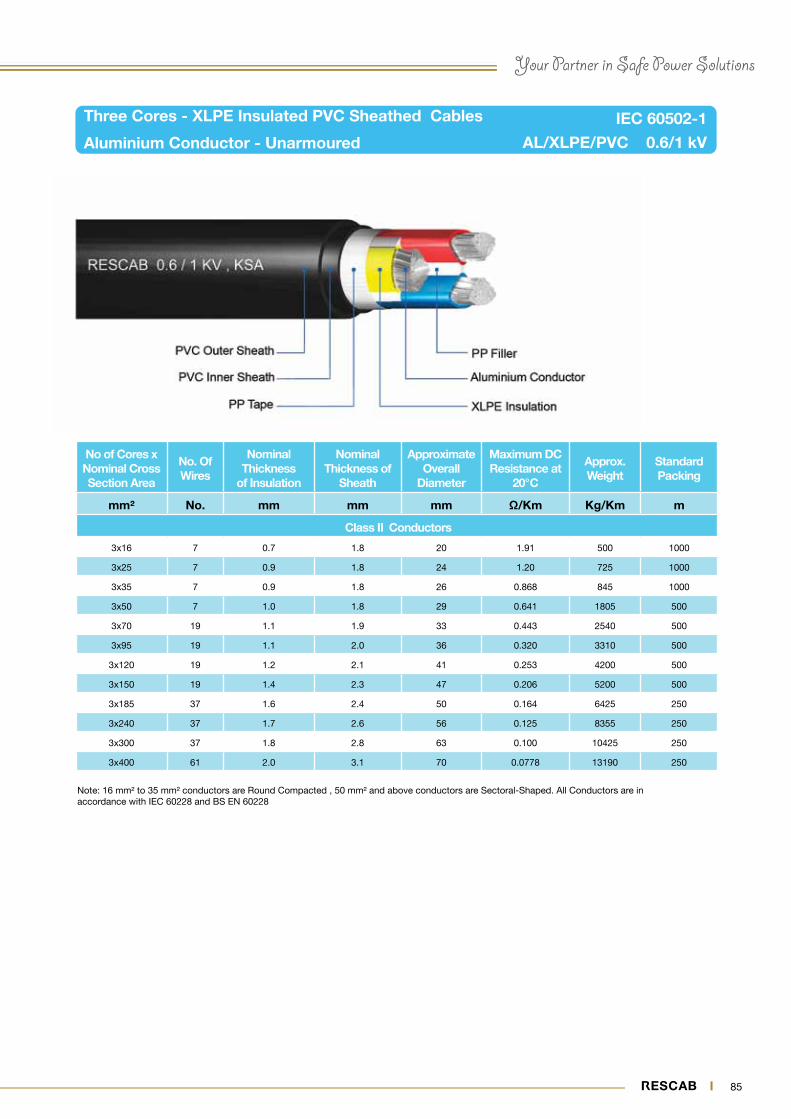
84 85
Your Partner in Safe Power Solutions
Note: 16 mm² to 35 mm² conductors are Round Compacted , 50 mm² and above conductors are Sectoral-Shaped. All Conductors are in accordance with IEC 60228 and BS EN 60228
Three Cores - XLPE Insulated PVC Sheathed Cables
Aluminium Conductor - Unarmoured AL/XLPE/PVC 0.6/1 kV
IEC 60502-1
No of Cores x Nominal Cross Section Area
No. Of Wires
Nominal Thickness
of Insulation
Nominal Thickness of
Sheath
Approximate Overall
Diameter
Maximum DC Resistance at
20°C
Approx. Weight
Standard Packing
mm² No. mm mm mm Ω/Km Kg/Km m
Class II Conductors
3x16 7 0.7 1.8 20 1.91 500 1000
3x25 7 0.9 1.8 24 1.20 725 1000
3x35 7 0.9 1.8 26 0.868 845 1000
3x50 7 1.0 1.8 29 0.641 1805 500
3x70 19 1.1 1.9 33 0.443 2540 500
3x95 19 1.1 2.0 36 0.320 3310 500
3x120 19 1.2 2.1 41 0.253 4200 500
3x150 19 1.4 2.3 47 0.206 5200 500
3x185 37 1.6 2.4 50 0.164 6425 250
3x240 37 1.7 2.6 56 0.125 8355 250
3x300 37 1.8 2.8 63 0.100 10425 250
3x400 61 2.0 3.1 70 0.0778 13190 250

86 87
Note: 16 mm² to 35 mm² conductors are Round Compacted , 50 mm² and above conductors are Sectoral-Shaped. All Conductors are in accordance with IEC 60228 and BS EN 60228
Four Cores - XLPE Insulated PVC Sheathed Cables
Aluminium Conductor - Unarmoured AL/XLPE/PVC 0.6/1 kV
IEC 60502-1
No. of Cores x Nominal Cross Section Area
No. Of Wires
Nominal Thickness of
Insulation
Nominal Thickness of
Sheath
Approximate Overall
Diameter
Maximum DC Resistance at
20°C
Approx. Weight
Standard Packing
mm² No. mm mm mm Ω/Km Kg/Km m
Class II Conductors
4x16 7 0.7 1.8 22 1.91 610 1000
4x25 7 0.9 1.8 26 1.20 860 1000
4x35 7 0.9 1.8 29 0.868 890 1000
4x50 7 1.0 1.9 31 0.641 1060 500
4x70 19 1.1 2.0 36 0.443 1415 500
4x95 19 1.1 2.1 40 0.320 1820 500
4x120 37 1.2 2.3 44 0.253 2255 500
4x150 37 1.4 2.5 49 0.206 2745 500
4x185 37 1.6 2.6 53 0.164 3355 250
4x240 37 1.7 2.8 59 0.125 4295 250
4x300 37 1.8 3.0 65 0.100 5185 250
4x400 61 2.0 3.3 74 0.0778 6655 250

86 87
Your Partner in Safe Power Solutions
Note: Phase conductors 25 mm² and 35 mm² are Round Compacted, 50 mm² and above are Sectoral-Shaped. Neutral Conductors 16 mm² and above are Round Compacted. All Conductors are in accordance with IEC 60228 and BS EN 60228
Three & Half Cores - XLPE Insulated PVC Sheathed Cables
Aluminium Conductor - Unarmoured
IEC 60502-1
No. of Cores x Nominal Cross Section Area
No. Of WiresNominal
Thickness of Insulation
Nominal Thickness of Sheath
Approx. Overall
Diameter
Maximum DC Resistance at
20°CApprox. Weight
Standard Packing
Ph Ne Ph Ne Ph Ne
mm² No. No. mm mm mm mm Ω/Km Ω/Km Kg/Km m
Class II Conductors
3x25 + 16 7 7 0.9 0.7 1.8 26 1.20 1.91 750 1000
3x35 + 16 7 7 0.9 0.7 1.8 27 0.868 1.91 810 1000
3x50 + 25 7 7 1.0 0.9 1.8 30 0.641 1.20 1005 500
3x70 + 35 19 7 1.1 0.9 1.9 35 0.443 0.868 1340 500
3x95 + 50 19 7 1.1 1.0 2.1 39 0.320 0.641 1730 500
3x120 + 70 37 19 1.2 1.1 2.2 43 0.253 0.443 2075 500
3x150 + 70 37 19 1.4 1.1 2.3 47 0.206 0.443 2529 500
3x185 + 95 37 19 1.6 1.1 2.5 52 0.164 0.320 3105 250
3x240 + 120 37 37 1.7 1.2 2.7 58 0.125 0.253 3840 250
3x300 + 150 37 37 1.8 1.4 2.9 63 0.100 0.206 4770 250
3x400 + 185 61 37 2.0 1.6 3.1 72 0.0778 0.164 4870 250
AL/XLPE/PVC 0.6/1 KV
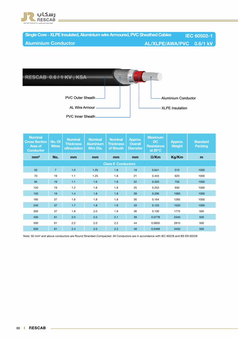
88 89
Note: 50 mm² and above conductors are Round Stranded-Compacted. All Conductors are in accordance with IEC 60228 and BS EN 60228
Single Core - XLPE Insulated, Aluminium wire Armoured, PVC Sheathed Cables
Aluminium Conductor AL/XLPE/AWA/PVC 0.6/1 kV
IEC 60502-1
Nominal Cross Section
Area of Conductor
No. Of Wires
Nominal Thickness
ofInsulation
Nominal Aluminium Wire Dia.
Nominal Thickness of Sheath
Approx. Overall
Diameter
Maximum DC
Resistance at 20°C
Approx. Weight
Standard Packing
mm² No. mm mm mm mm Ω/Km Kg/Km m
Class II Conductors
50 7 1.0 1.25 1.8 19 0.641 515 1000
70 19 1.1 1.25 1.8 21 0.443 620 1000
95 19 1.1 1.6 1.8 22 0.320 750 1000
120 19 1.2 1.8 1.8 25 0.253 930 1000
150 19 1.4 1.8 1.8 28 0.206 1060 1000
185 37 1.6 1.8 1.8 30 0.164 1265 1000
240 37 1.7 1.8 1.9 33 0.125 1520 1000
300 37 1.8 2.0 1.9 36 0.100 1775 500
400 61 2.0 2.0 2.1 39 0.0778 2340 500
500 61 2.2 2.0 2.2 44 0.0605 2810 500
630 61 2.4 2.0 2.3 49 0.0469 3450 500

88 89
Your Partner in Safe Power Solutions
Note: 16 mm² and above conductors are Round Stranded-Compacted. All Conductors are in accordance with IEC 60228 and BS EN 60228
Two Cores - XLPE Insulated, Steel Wire Armoured, PVC Sheathed Cables
Aluminium Conductor AL/XLPE/SWA/PVC 0.6/1 kV
IEC 60502-1
Nominal Cross Section Area of
Conductor
No. Of Wires
Nominal Thickness
of Insulation
Nominal Steel Wire
Dia.
Nominal Thickness of Sheath
Approx. Overall
Diameter
Maximum DC
Resistance at 20°C
Approx. Weight
Standard Packing
mm² No. mm mm mm mm Ω/Km Kg/Km m
Class II Conductors
2x16 7 0.7 1.25 1.8 22 1.91 850 1000
2x25 7 0.9 1.6 1.8 26 1.20 1265 1000
2x35 7 0.9 1.6 1.8 28 0.868 1495 1000

90 91
Note: 16 mm² to 35 mm² conductors are Round Compacted , 50 mm² and above conductors are Sectoral-Shaped. All Conductors are in accordance with IEC 60228 and BS EN 60228
Three Cores - XLPE Insulated, Steel Wire Armoured, PVC Sheathed Cables
Aluminium Conductor AL/XLPE/SWA/PVC 0.6/1 kV
IEC 60502-1
No of Cores x Nominal Cross Section Area
No. Of Wires
Nominal Thickness of
Insulation
Nominal Steel Wire
Dia.
Nominal Thickness of Sheath
Approx. Overall
Diameter
Maximum DC
Resistance at 20°C
Approx. Weight
Standard Packing
mm² No. mm mm mm mm Ω/Km Kg/Km m
Class II Conductors
3x16 7 0.7 1.25 1.8 23 1.91 945 1000
3x25 7 0.9 1.6 1.8 27 1.20 1425 1000
3x35 7 0.9 1.6 1.8 29 0.868 1655 1000
3x50 7 1.0 1.6 1.9 32 0.641 2670 500
3x70 19 1.1 2.0 2.0 37 0.443 3830 500
3x95 19 1.1 2.0 2.2 40 0.320 4755 500
3x120 19 1.2 2.0 2.3 45 0.253 5815 500
3x150 19 1.4 2.5 2.5 53 0.206 7435 500
3x185 37 1.6 2.5 2.6 55 0.164 8925 250
3x240 37 1.7 2.5 2.8 62 0.125 11190 250
3x300 37 1.8 2.5 3.0 68 0.100 13540 250
3x400 61 2.0 2.5 3.2 75 0.0778 16600 250

90 91
Your Partner in Safe Power Solutions
Note: 16 mm² to 35 mm² conductors are Round Compacted , 50 mm² and above conductors are Sectoral-Shaped. All Conductors are in accordance with IEC 60228 and BS EN 60228
Four Cores - XLPE Insulated, Steel Wire Armoured, PVC Sheathed Cables
Aluminium Conductor AL/XLPE/SWA/PVC 0.6/1 kV
IEC 60502-1
No of Cores x Nominal Cross Section Area
No. Of Wires
Nominal Thickness of
Insulation
Nominal Steel Wire
Dia.
Nominal Thickness of Sheath
Approximate Overall
Diameter
Maximum DC
Resistance at 20°C
Approx. Weight
Standard Packing
mm² No. mm mm mm mm Ω/Km Kg/Km m
Class II Conductors
4x16 7 0.7 1.6 1.8 25 1.91 1195 1000
4x25 7 0.9 1.6 1.8 30 1.20 1545 1000
4x35 7 0.9 1.6 1.9 32 0.868 1700 1000
4x50 7 1.0 1.6 2.0 35 0.641 1920 500
4x70 19 1.1 2.0 2.2 40 0.443 2720 500
4x95 19 1.1 2.0 2.3 43 0.320 3250 500
4x120 37 1.2 2.5 2.5 49 0.253 4285 500
4x150 37 1.4 2.5 2.6 54 0.206 4995 500
4x185 37 1.6 2.5 2.8 59 0.164 5790 250
4x240 37 1.7 2.5 3.0 65 0.125 7070 250
4x300 37 1.8 2.5 3.2 70 0.100 8370 250
4x400 61 2.0 3.15 3.5 80 0.0778 11150 250
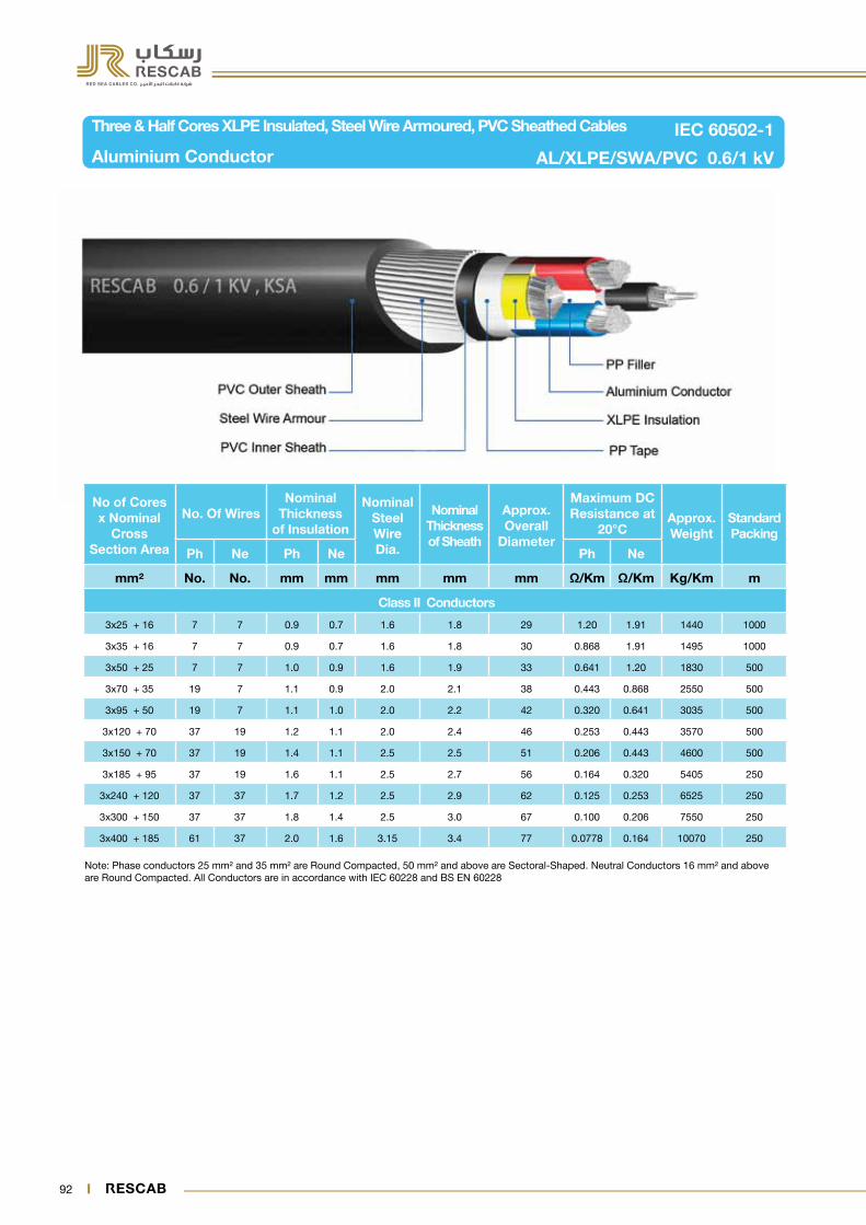
92 93
Note: Phase conductors 25 mm² and 35 mm² are Round Compacted, 50 mm² and above are Sectoral-Shaped. Neutral Conductors 16 mm² and above are Round Compacted. All Conductors are in accordance with IEC 60228 and BS EN 60228
Three & Half Cores XLPE Insulated, Steel Wire Armoured, PVC Sheathed Cables
Aluminium Conductor AL/XLPE/SWA/PVC 0.6/1 kV
IEC 60502-1
No of Cores x Nominal
Cross Section Area
No. Of WiresNominal
Thickness of Insulation
Nominal Steel Wire Dia.
Nominal Thickness of Sheath
Approx. Overall
Diameter
Maximum DC Resistance at
20°CApprox. Weight
Standard Packing
Ph Ne Ph Ne Ph Ne
mm² No. No. mm mm mm mm mm Ω/Km Ω/Km Kg/Km m
Class II Conductors
3x25 + 16 7 7 0.9 0.7 1.6 1.8 29 1.20 1.91 1440 1000
3x35 + 16 7 7 0.9 0.7 1.6 1.8 30 0.868 1.91 1495 1000
3x50 + 25 7 7 1.0 0.9 1.6 1.9 33 0.641 1.20 1830 500
3x70 + 35 19 7 1.1 0.9 2.0 2.1 38 0.443 0.868 2550 500
3x95 + 50 19 7 1.1 1.0 2.0 2.2 42 0.320 0.641 3035 500
3x120 + 70 37 19 1.2 1.1 2.0 2.4 46 0.253 0.443 3570 500
3x150 + 70 37 19 1.4 1.1 2.5 2.5 51 0.206 0.443 4600 500
3x185 + 95 37 19 1.6 1.1 2.5 2.7 56 0.164 0.320 5405 250
3x240 + 120 37 37 1.7 1.2 2.5 2.9 62 0.125 0.253 6525 250
3x300 + 150 37 37 1.8 1.4 2.5 3.0 67 0.100 0.206 7550 250
3x400 + 185 61 37 2.0 1.6 3.15 3.4 77 0.0778 0.164 10070 250
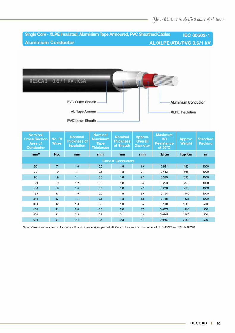
92 93
Your Partner in Safe Power Solutions
Note: 50 mm² and above conductors are Round Stranded-Compacted. All Conductors are in accordance with IEC 60228 and BS EN 60228
Single Core - XLPE Insulated, Aluminium Tape Armoured, PVC Sheathed Cables
Aluminium Conductor AL/XLPE/ATA/PVC 0.6/1 kV
IEC 60502-1
Nominal Cross Section
Area of Conductor
No. Of Wires
Nominal Thickness of
Insulation
Nominal Aluminium
Tape Thickness
Nominal Thickness of Sheath
Approx. Overall
Diameter
Maximum DC
Resistance at 20°C
Approx. Weight
Standard Packing
mm² No. mm mm mm mm Ω/Km Kg/Km m
Class II Conductors50 7 1.0 0.5 1.8 19 0.641 480 1000
70 19 1.1 0.5 1.8 21 0.443 565 1000
95 19 1.1 0.5 1.8 22 0.320 695 1000
120 19 1.2 0.5 1.8 24 0.253 790 1000
150 19 1.4 0.5 1.8 27 0.206 920 1000
185 37 1.6 0.5 1.8 29 0.164 1100 1000
240 37 1.7 0.5 1.8 32 0.125 1325 1000
300 37 1.8 0.5 1.9 35 0.100 1595 500
400 61 2.0 0.5 2.0 37 0.0778 1990 500
500 61 2.2 0.5 2.1 42 0.0605 2450 500
630 61 2.4 0.5 2.3 47 0.0469 3060 500

94 95
Note: 16 mm² and above conductors are Round Stranded-Compacted. All Conductors are in accordance with IEC 60228 and BS EN 60228
Two Cores - XLPE Insulated, Steel Tape Armoured, PVC Sheathed Cables
Aluminium Conductor AL/XLPE/STA/PVC 0.6/1 kV
IEC 60502-1
Nominal Cross Section
Area of Conductor
No. Of Wires
Nominal Thickness
of Insulation
Nominal Steel Tape Thickness
Nominal Thickness of Sheath
Approx. Overall
Diameter
Maximum DC
Resistance at 20°C
Approx. Weight
Standard Packing
mm² No. mm mm mm mm Ω/Km Kg/Km m
Class II Conductors
2x16 7 0.7 0.2 1.8 20 1.91 580 1000
2x25 7 0.9 0.2 1.8 24 1.20 790 1000
2x35 7 0.9 0.2 1.8 26 0.868 975 1000

94 95
Your Partner in Safe Power Solutions
Note: 16 mm² to 35 mm² conductors are Round Compacted , 50 mm² and above conductors are Sectoral-Shaped. All Conductors are in accordance with IEC 60228 and BS EN 60228
Three Cores - XLPE Insulated, Steel Tape Armoured, PVC Sheathed Cables
Aluminium Conductor AL/XLPE/STA/PVC 0.6/1 kV
IEC 60502-1
No of Cores x Nominal
Cross Section Area
No. Of Wires
Nominal Thickness
of Insulation
Nominal Steel Tape Thickness
Nominal Thickness of Sheath
Approx. Overall
Diameter
Maximum DC
Resistance at 20°C
Approx. Weight
Standard Packing
mm² No. mm mm mm mm Ω/Km Kg/Km m
Class II Conductors
3x16 7 0.7 0.2 1.8 21 1.91 660 1000
3x25 7 0.9 0.2 1.8 25 1.20 895 1000
3x35 7 0.9 0.2 1.8 27 0.868 945 1000
3x50 7 1.0 0.2 1.8 31 0.641 2060 500
3x70 19 1.1 0.2 2.0 35 0.443 2840 500
3x95 19 1.1 0.2 2.1 39 0.320 3750 500
3x120 19 1.2 0.5 2.3 45 0.253 5055 500
3x150 19 1.4 0.5 2.4 50 0.206 6130 500
3x185 37 1.6 0.5 2.6 55 0.164 7450 250
3x240 37 1.7 0.5 2.7 62 0.125 9500 250
3x300 37 1.8 0.5 2.9 68 0.100 11580 250
3x400 61 2.0 0.5 3.2 75 0.0778 14655 250

96 97
Note: 16 mm² to 35 mm² conductors are Round Compacted , 50 mm² and above conductors are Sectoral-Shaped. All Conductors are in accordance with IEC 60228 and BS EN 60228
Four Cores - XLPE Insulated, Steel Tape Armoured, PVC Sheathed Cables
Aluminium Conductor AL/XLPE/STA/PVC 0.6/1 kV
IEC 60502-1
No of Cores x Nominal
Cross Section Area
No. Of Wires
Nominal Thickness
of Insulation
Nominal Steel Tape Thickness.
Nominal Thickness of Sheath
Approx. Overall
Diameter
Maximum DC
Resistance at 20°C
Approx. Weight
Standard Packing
mm² No. mm mm mm mm Ω/Km Kg/Km m
Class II Conductors
4x16 7 0.7 0.2 1.8 23 1.91 765 1000
4x25 7 0.9 0.2 1.8 27 1.20 1050 1000
4x35 7 0.9 0.2 1.8 28 0.868 1000 1000
4x50 7 1.0 0.2 1.9 32 0.641 1260 500
4x70 19 1.1 0.2 2.1 38 0.443 1660 500
4x95 19 1.1 0.5 2.3 42 0.320 2495 500
4x120 37 1.2 0.5 2.4 46 0.253 2990 500
4x150 37 1.4 0.5 2.6 51 0.206 3585 500
4x185 37 1.6 0.5 2.7 55 0.164 4115 250
4x240 37 1.7 0.5 2.9 62 0.125 5300 250
4x300 37 1.8 0.5 3.1 67 0.100 6305 250
4x400 61 2.0 0.5 3.4 76 0.0778 7930 250

96 97
Your Partner in Safe Power Solutions
Note: Phase conductors 25 mm² and 35 mm² are Round Compacted, 50 mm² and above are Sectoral-Shaped. Neutral Conductors 16 mm² and above are Round Compacted. All Conductors are in accordance with IEC 60228 and BS EN 60228
Three & Half Cores XLPE Insulated, Steel Tape Armoured, PVC Sheathed Cables
Aluminium Conductor AL/XLPE/STA/PVC 0.6/1 kV
IEC 60502-1
No of Cores x Nominal
Cross Section Area
No. Of WiresNominal
Thickness of Insulation
Nominal Steel Tape Thickness
Nominal Thickness of Sheath
Approx. Overall
Diameter
Maximum DC Resistance at
20°CApprox. Weight
Standard Packing
Ph Ne Ph Ne Ph Ne
mm² No. No. mm mm mm mm mm Ω/Km Ω/Km Kg/Km m
Class II Conductors
3x25 + 16 7 7 0.9 0.7 0.2 1.8 26 1.20 1.91 905 1000
3x35 + 16 7 7 0.9 0.7 0.2 1.8 27 0.868 1.91 920 1000
3x50 + 25 7 7 1.0 0.9 0.2 1.9 30 0.641 1.20 1170 500
3x70 + 35 19 7 1.1 0.9 0.2 2.0 34 0.443 0.868 1540 500
3x95 + 50 19 7 1.1 1.0 0.5 2.2 40 0.320 0.641 2260 500
3x120 + 70 37 19 1.2 1.1 0.5 2.3 44 0.253 0.443 2700 500
3x150 + 70 37 19 1.4 1.1 0.5 2.5 48 0.206 0.443 3230 500
3x185 + 95 37 19 1.6 1.1 0.5 2.6 53 0.164 0.320 3860 250
3x240 + 120 37 37 1.7 1.2 0.5 2.8 59 0.125 0.253 5250 250
3x300 + 150 37 37 1.8 1.4 0.5 3.0 64 0.100 0.206 5740 250
3x400 + 185 61 37 2.0 1.6 0.5 3.3 72 0.0778 0.164 7130 250
98
RESCAB vision is to supply safe and reliable products complying with best quality standards, continually enhance product quality through efficient quality management
systems and provide efficient after-sales service.
For more information, contact us at:
Red Sea Cables Company (RESCAB)P.O Box 859 - Riyadh - 11421 Kingdom of Saudia Arabia
E-mail: [email protected] & [email protected]: 00966 1 288 6303 Fax: 00966 1 288 63 02
To know more about RESCAB products and services, please visit: www.rescab.com
Your Partner in Safe Power Solutions

Red Sea Cables Company (RESCAB)P.O Box 859 - Riyadh: 11421 - Kingdom of Saudia Arabia
Tel: 00966 1 288 6303 Fax: 00966 1 288 63 02E-mail: [email protected] & [email protected] - www.rescab.com
Red Sea Cables Co.


