140
5SL-28199-10 LIT-11626-16-45 YZF-R6R(C) OWNER’S MANUAL

PRINTED IN JAPAN2002.11-7.3×1 CR
(E)
PRINTED ON RECYCLED PAPER YAMAHA MOTOR CO., LTD.
5SL-28199-10LIT-11626-16-45
YZF-R6R(C)
OWNER’S MANUAL

EAU03438

00002 INTRODUCTION
ZF-R6(C). This model is the of fine sporting, touring, and degree of craftsmanship andlds.
peration, inspection, and basictions concerning the operationYamaha dealer.
cle fully comply with the emis- manufacture. Yamaha has metr economy of operation of the important that you and youred maintenance schedules and
U5SL10.book Page 1 Friday, November 1, 2002 4:33 PM
EAU
Congratulations on your purchase of the Yamaha Yresult of Yamaha’s vast experience in the productionpacesetting racing machines. It represents the highreliability that have made Yamaha a leader in these fie
This manual will give you an understanding of the omaintenance of this motorcycle. If you have any quesor maintenance of your motorcycle, please consult a
The design and manufacture of this Yamaha motorcysions standards for clean air applicable at the date ofthese standards without reducing the performance omotorcycle. To maintain these high standards, it isYamaha dealer pay close attention to the recommendoperating instructions contained within this manual.

EAU00003PORTANT MANUAL INFORMATION
ticularly important information is distinguished in this manual by the following notations:
ERT! YOUR SAFETY IS
U5SL10.book Page 1 Friday, November 1, 2002 4:33 PM
IM
Par
re injury or death to thepairing the motorcycle.
to avoid damage to the
learer.
torcycle and should remain
d quality. Therefore, whilelable at the time of printing,d this manual. If you haveaha dealer.
C
N
The Safety Alert Symbol meINVOLVED!
WARNING Failure to follow WARNING inmotorcycle operator, a bystan
AUTION: A CAUTION indicates specialmotorcycle.
OTE: A NOTE provides key informati
NOTE:_
� This manual should be considwith it even if the motorcycle
� Yamaha continually seeks adthis manual contains the mosthere may be minor discrepaany questions concerning this
_
ans ATTENTION! BECOME AL
structions could result in seveder or a person inspecting or re
precautions that must be taken
on to make procedures easier or c
ered a permanent part of this mois subsequently sold.vancements in product design ant current product information avaincies between your motorcycle an manual, please consult your Yam

IMPORTANT MANUAL INFORMATIONEW000000
IS MANUAL AND THE “YOU AND YOUR MOTORCYCLE: RIDINGAREFULLY AND COMPLETELY BEFORE OPERATING THIS MOTOR-TTEMPT TO OPERATE THIS MOTORCYCLE UNTIL YOU HAVE AT-E KNOWLEDGE OF ITS CONTROLS AND OPERATING FEATURESAVE BEEN TRAINED IN SAFE AND PROPER RIDING TECHNIQUES.TIONS AND CAREFUL MAINTENANCE, ALONG WITH GOOD RIDINGURE THAT YOU SAFELY ENJOY THE CAPABILITIES AND THE RELI-OTORCYCLE.
U5SL10.book Page 2 Friday, November 1, 2002 4:33 PM
WARNING_
PLEASE READ THTIPS” BOOKLET CCYCLE. DO NOT ATAINED ADEQUATAND UNTIL YOU HREGULAR INSPECSKILLS, WILL ENSABILITY OF THIS M_
IMPORTANT MANUAL INFORMATION
AFFIX DEALER
EAU04247
©2002
Aw
Y
U5SL10.book Page 3 Friday, November 1, 2002 4:33 PM
LABEL HERE
YZF-R6R(C)OWNER’S MANUAL
by Yamaha Motor Corporation, U.S.A.1st edition, October 2002
All rights reserved.ny reprinting or unauthorized useithout the written permission of
amaha Motor Corporation, U.S.A.is expressly prohibited.
Printed in Japan.P/N LIT-11626-16-45

LE OF CONTENTS
1
2
FUNCTIONS 3
4
T RIDING POINTS 5
D MINOR REPAIR 6
ORAGE 7
8
9
EAU00009
U5SL10.book
TAB
1 SAFETY INFORMATION
2 DESCRIPTION
3 INSTRUMENT AND CONTROL
4 PRE-OPERATION CHECKS
5 OPERATION AND IMPORTAN
6 PERIODIC MAINTENANCE AN
7 MOTORCYCLE CARE AND ST
8 SPECIFICATIONS
9 CONSUMER INFORMATION
Page 1 Friday, November 1, 2002 4:33 PM
INDEX

SAFETY INFORMATION
1
Safe riding .......................................................................................... 1-1Protective apparel .............................................................................. 1-3Modifications ...................................................................................... 1-3Loading and accessories ................................................................... 1-3Gasoline and exhaust gas.................................................................. 1-5Location of important labels .............................................................. 1-7
U5SL10.book Page 1 Friday, November 1, 2002 4:33 PM

1
2
3
4
5
6
7
8
9
EAU04193
FE USE AND OPERATION AREES AS WELL AS THE EXPERTISEE FOLLOWING REQUIREMENTS
U5SL10.book Page 1 Friday, November 1, 2002 4:33 PM
SOURCE ON ALL ASPECTS OF
IREMENTS IN THE OWNER’S
G TECHNIQUES.TED BY THE OWNER’S MANUALITIONS.
event an accident.er.raffic is the predominating cause ofaused by an automobile driver whos to be very effective in reducing the
rough intersections, since intersec-ccur.her motorist’s blind spot.
1-1
1-SAFETY INFORMATION
MOTORCYCLES ARE SINGLE TRACK VEHICLES. THEIR SADEPENDENT UPON THE USE OF PROPER RIDING TECHNIQUOF THE OPERATOR. EVERY OPERATOR SHOULD KNOW THBEFORE RIDING THIS MOTORCYCLE.HE OR SHE SHOULD:1. OBTAIN THOROUGH INSTRUCTIONS FROM A COMPETENT
MOTORCYCLE OPERATION.2. OBSERVE THE WARNINGS AND MAINTENANCE REQU
MANUAL.3. OBTAIN QUALIFIED TRAINING IN SAFE AND PROPER RIDIN4. OBTAIN PROFESSIONAL TECHNICAL SERVICE AS INDICA
AND/OR WHEN MADE NECESSARY BY MECHANICAL COND
Safe riding
1. Always make pre-operation checks. Careful checks may help pr2. This motorcycle is designed to carry the operator and a passeng3. The failure of motorists to detect and recognize motorcycles in t
automobile/motorcycle accidents. Many accidents have been cdid not see the motorcycle. Making yourself conspicuous appearchance of this type of accident.
Therefore:a. Wear a brightly colored jacket.b. Use extra caution when you are approaching and passing th
tions are the most likely places for motorcycle accidents to oc. Ride where other motorists can see you. Avoid riding in anot

FETY INFORMATION
1
2
3
4
5
6
7
8
9
operators who have been involved in
r motorcycle to other qualified opera-
elp you to avoid an accident.here there is no traffic until you have controls.perator. A typical error made by the or undercornering (insufficient lean
rranted by road and traffic conditions.that other motorists can see you.er control.d both feet on the operator footrests
at strap or grab bar, if equipped, with
both feet on the passenger footrests.
le for off-road use.
U5SL10.book Page 2 Friday, November 1, 2002 4:33 PM
SA
1-2
4. Many accidents involve inexperienced operators. In fact, many accidents do not even have a current motorcycle license.a. Make sure that you are qualified and that you only lend you
tors.b. Know your skills and limits. Staying within your limits may hc. We recommend that you practice riding your motorcycle w
become thoroughly familiar with the motorcycle and all of its5. Many accidents have been caused by error of the motorcycle o
operator is veering wide on a turn due to EXCESSIVE SPEEDangle for the speed).a. Always obey the speed limit and never travel faster than wab. Always signal before turning or changing lanes. Make sure
6. The posture of the operator and passenger is important for propa. The operator should keep both hands on the handlebar an
during operation to maintain control of the motorcycle.b. The passenger should always hold onto the operator, the se
both hands and keep both feet on the passenger footrests.c. Never carry a passenger unless he or she can firmly place
7. Never ride under the influence of alcohol or other drugs.8. This motorcycle is designed for on-road use only. It is not suitab

1
2
3
4
5
6
7
8
9
f head injuries. The use of a safetyon of head injuries.
ld contribute to an impairment of vi-
tive in preventing or reducing abra-
e control levers, footrests, or wheels
ion. They become very hot and cangs, ankles, and feet.
r the removal of original equipment, personal injury. Modifications may
affect stability and handling if thesibility of an accident, use extreme. Use extra care when riding aneral guidelines to follow if loading
U5SL10.book Page 3 Friday, November 1, 2002 4:33 PM
SAFETY INFORMATION
1-3
Protective apparel
The majority of fatalities from motorcycle accidents are the result ohelmet is the single most critical factor in the prevention or reducti1. Always wear an approved helmet.2. Wear a face shield or goggles. Wind in your unprotected eyes cou
sion that could delay seeing a hazard.3. The use of a jacket, heavy boots, trousers, gloves, etc., is effec
sions or lacerations.4. Never wear loose-fitting clothes, otherwise they could catch on th
and cause injury or an accident.5. Never touch the engine or exhaust system during or after operat
cause burns. Always wear protective clothing that covers your le6. A passenger should also observe the above precautions.
Modifications
Modifications made to this motorcycle not approved by Yamaha, omay render the motorcycle unsafe for use and may cause severealso make your motorcycle illegal to use.
Loading and accessories
Adding accessories or cargo to your motorcycle can adversely weight distribution of the motorcycle is changed. To avoid the poscaution when adding cargo or accessories to your motorcyclemotorcycle that has added cargo or accessories. Here are some gecargo or adding accessories to your motorcycle:

FETY INFORMATION
1
2
3
4
5
6
7
8
9
rgo must not exceed the maximumhen loading within this weight limit,
to the motorcycle as possible. Make of the motorcycle to minimize imbal-
t accessories and cargo are securelynts and cargo restraints frequently.ork, or front fender. These items, in-n create unstable handling or a slow
for use on this motorcycle. Sinceyou must personally be responsiblessories. Use extreme caution when
der “Loading” when mounting acces-
rformance of your motorcycle. Care- does not in any way reduce grounding travel or control operation, or ob-
U5SL10.book Page 4 Friday, November 1, 2002 4:33 PM
SA
1-4
Loading
The total weight of the operator, passenger, accessories and caload limit of YZF-R6: 193 kg (426 lb) / YZF-R6C: 192 kg (423 lb). Wkeep the following in mind:1. Cargo and accessory weight should be kept as low and close
sure to distribute the weight as evenly as possible on both sidesance or instability.
2. Shifting weights can create a sudden imbalance. Make sure thaattached to the motorcycle before riding. Check accessory mou
3. Never attach any large or heavy items to the handlebar, front fcluding such cargo as sleeping bags, duffel bags, or tents, casteering response.
Accessories
Genuine Yamaha accessories have been specifically designedYamaha cannot test all other accessories that may be available, for the proper selection, installation and use of non-Yamaha acceselecting and installing any accessories.Keep the following guidelines in mind, as well as those provided unsories.1. Never install accessories or carry cargo that would impair the pe
fully inspect the accessory before using it to make sure that itclearance or cornering clearance, limit suspension travel, steerscure lights or reflectors.

1
2
3
4
5
6
7
8
9
n create instability due to improperare added to the handlebar or front be kept to a minimum. the motorcycle due to aerodynamicycle may become unstable in cross
assing or being passed by large ve-
normal riding position. This improp-d may limit control ability, therefore,
essories exceed the capacity of theich could cause a dangerous loss of
system when refueling..d area. The exhaust fumes are poi- a short time. Always operate your
nded and remove the key from the
U5SL10.book Page 5 Friday, November 1, 2002 4:33 PM
SAFETY INFORMATION
1-5
a. Accessories fitted to the handlebar or the front fork area caweight distribution or aerodynamic changes. If accessories fork area, they must be as lightweight as possible and should
b. Bulky or large accessories may seriously affect the stability ofeffects. Wind may attempt to lift the motorcycle, or the motorcwinds. These accessories may also cause instability when phicles.
c. Certain accessories can displace the operator from his or herer position limits the freedom of movement of the operator ansuch accessories are not recommended.
2. Use caution when adding electrical accessories. If electrical accmotorcycle’s electrical system an electric failure could result, whlights or engine power.
Gasoline and exhaust gas
1. GASOLINE IS HIGHLY FLAMMABLE:a. Always turn the engine off when refueling.b. Take care not to spill any gasoline on the engine or exhaust c. Never refuel while smoking or in the vicinity of an open flame
2. Never start the engine or let it run for any length of time in a closesonous and may cause loss of consciousness and death withinmotorcycle in an area that has adequate ventilation.
3. Always turn the engine off before leaving the motorcycle unattemain switch. When parking the motorcycle, note the following:

FETY INFORMATION
1
2
3
4
5
6
7
8
9
the motorcycle in a place where pe-
wise it may fall over., a kerosene heater, or near an open
re that it is kept upright. If the motor-
or, or allow gasoline to get into yourr skin or clothing, immediately wash
.
U5SL10.book Page 6 Friday, November 1, 2002 4:33 PM
SA
1-6
a. The engine and exhaust system may be hot, therefore, parkdestrians or children are not likely to touch these hot areas.
b. Do not park the motorcycle on a slope or soft ground, otherc. Do not park the motorcycle near a flammable source, (e.g.
flame), otherwise it could catch fire.4. When transporting the motorcycle in another vehicle, make su
cycle should lean over, gasoline may leak out of the fuel tank.5. If you should swallow any gasoline, inhale a lot of gasoline vap
eyes, see your doctor immediately. If any gasoline spills on youthe affected area with soap and water and change your clothes

1
2
3
4
5
6
7
8
9
EAU02977
LoPle
U5SL10.book Page 7 Friday, November 1, 2002 4:33 PM
SAFETY INFORMATION
1-7
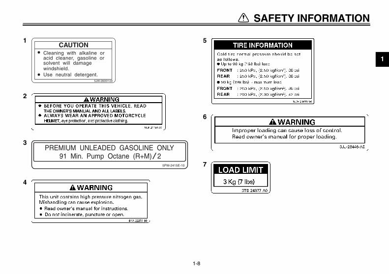
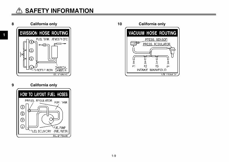
cation of important labels ase read the following important labels carefully before operating this motorcycle.
FETY INFORMATION
1
2
3
4
5
6
7
8
9
1
2
3
4
U5SL10.book Page 8 Friday, November 1, 2002 4:33 PM
SA
1-8
PREMIUM UNLEADED GASOLINE ONLY91 Min. Pump Octane (R+M) 2
5PW-2415E-10
5CAUTION
Cleaning with alkaline oracid cleaner, gasoline orsolvent will damagewindshield.Use neutral detergent.
5JW-2835Y-00
6
7
1
2
3
4
5
6
7
8
9
8
9
only
U5SL10.book Page 9 Friday, November 1, 2002 4:33 PM
SAFETY INFORMATION
1-9
California only 10
California only
California

DESCRIPTION
2
Left view ............................................................................................. 2-1Right view........................................................................................... 2-2Controls and instruments ................................................................... 2-3
U5SL10.book Page 1 Friday, November 1, 2002 4:33 PM
2
EAU00026
U5SL10.book Page 1 Friday, November 1, 2002 4:33 PM
2-DE
Le
(page 6-1)mbly rebound
ting screw (page 3-22)(page 3-12)(page 6-15)
dge (page 6-16)on damping force
(page 3-20)
1.
2.3.4.5.
6.
2-1
SCRIPTION
ft view
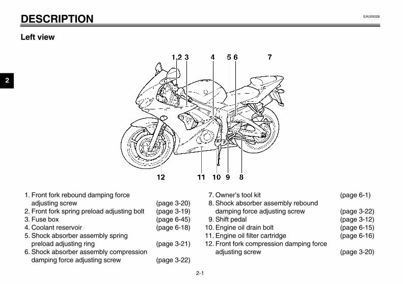
Front fork rebound damping force adjusting screw (page 3-20)Front fork spring preload adjusting bolt (page 3-19)Fuse box (page 6-45)Coolant reservoir (page 6-18)Shock absorber assembly spring preload adjusting ring (page 3-21)Shock absorber assembly compression damping force adjusting screw (page 3-22)
7. Owner’s tool kit8. Shock absorber asse
damping force adjus9. Shift pedal
10. Engine oil drain bolt11. Engine oil filter cartri12. Front fork compressi
adjusting screw

DESCRIPTION
2
R
131415161718
(page 6-21)(page 6-21)(page 6-15)(page 3-13)(page 6-14)
ervoir (page 6-36)
U5SL10.book Page 2 Friday, November 1, 2002 4:33 PM
2-2
ight view
. Luggage strap holder (page 3-23)
. Helmet holder (page 3-17)
. Main fuse (page 6-45)
. Battery (page 6-44)
. Air filter element (page 6-24)
. Front brake fluid reservoir (page 6-36)
19. Radiator cap20. Coolant drain bolt21. Engine oil filler cap22. Brake pedal23. Engine oil dipstick24. Rear brake fluid res
DE
2
Co
1.2.3.4.5.
ches (page 3-11)(page 6-28)(page 3-13)
U5SL10.book Page 3 Friday, November 1, 2002 4:33 PM
SCRIPTION
2-3
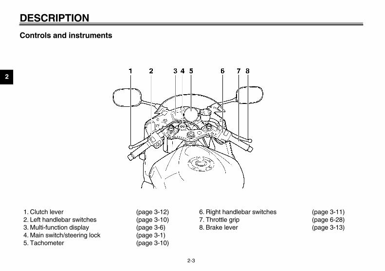
ntrols and instruments
Clutch lever (page 3-12)Left handlebar switches (page 3-10)Multi-function display (page 3-6)Main switch/steering lock (page 3-1)Tachometer (page 3-10)
6. Right handlebar swit7. Throttle grip8. Brake lever

INSTRUMENT AND CONTROL FUNCTIONS
3
Main switch/steering lock .................................................................. 3-1Indicator and warning lights ............................................................. 3-2Multi-function display ......................................................................... 3-6Tachometer ..................................................................................... 3-10Handlebar switches ......................................................................... 3-10Clutch lever ..................................................................................... 3-12Shift pedal ....................................................................................... 3-12Brake lever ...................................................................................... 3-13Brake pedal ..................................................................................... 3-13Fuel tank cap ................................................................................... 3-14Fuel ................................................................................................. 3-15Catalytic converter .......................................................................... 3-16Seats ............................................................................................... 3-16Helmet holders ................................................................................ 3-17Storage compartment ..................................................................... 3-18Adjusting the front fork .................................................................... 3-19Adjusting the shock absorber assembly .......................................... 3-21Luggage strap holders .................................................................... 3-23Sidestand ........................................................................................ 3-23Ignition circuit cut-off system ........................................................... 3-24
U5SL10.book Page 1 Friday, November 1, 2002 4:33 PM

3
EAU00027
U5SL10.book Page 1 Friday, November 1, 2002 4:33 PM
3-IN
EAU00040
CK steering is locked, and all electricaltems are off. The key can beoved.
lock the steeringTurn the handlebars all the way tothe left.Push the key in from the “OFF” po-sition, and then turn it to “LOCK”while still pushing it.Remove the key.
unlock the steeringh the key in, and then turn it toF” while still pushing it.
MaThethe usepos
3-1
STRUMENT AND CONTROL FUNCTIONS
EAU00029
in switch/steering lock main switch/steering lock controlsignition and lighting systems, and isd to lock the steering. The variousitions are described below.
EAU05002
ONAll electrical circuits are supplied withpower, and the meter lighting, taillight,license plate light and position lightscome on, and the engine can be start-ed. The key cannot be removed.
NOTE:_
The headlights come on automaticallywhen the engine is started and stay onuntil the key is turned to “OFF”, even ifthe engine stalls. _
EAU00038
OFFAll electrical systems are off. The keycan be removed.
LOThesysrem
To 1.
2.
3.
To Pus“OF

NTROL FUNCTIONS
3
@
N“Lmsymaccyke@
EAU04894
el level warning light “ ” is warning light comes on when the
el level drops below approximately5 L (0.77 Imp gal, 0.92 US gal).hen this occurs, refuel as soon asssible.e electrical circuit of the warning lightn be checked by turning the key toN”.the warning light does not come onr a few seconds, then go off, have amaha dealer check the electrical cir-it.
TE:is model is also equipped with a self-gnosis device for the fuel level de-
ction circuit. If the fuel level detectioncuit is defective, the following cyclell be repeated until the malfunction isrrected: The fuel level warning lightll flash eight times, then go off for5 seconds. If this occurs, have amaha dealer check the motorcycle.
1.2.
U5SL10.book Page 2 Friday, November 1, 2002 4:33 PM
INSTRUMENT AND CO
3-2
EW000016
WARNINGever turn the key to “OFF” orOCK” while the motorcycle isoving, otherwise the electricalstems will be switched off, whichay result in loss of control or ancident. Make sure that the motor-cle is stopped before turning they to “OFF” or “LOCK”.
EAU03034
Indicator and warning lights
EAU04121
Turn signal indicator lights “ ”and “ ” The corresponding indicator light flash-es when the turn signal switch ispushed to the left or right.
FuThfu3.WpoThca“OIf foYacu
NO_
Thdiatecirwicowi2.Ya_
Push.Turn.
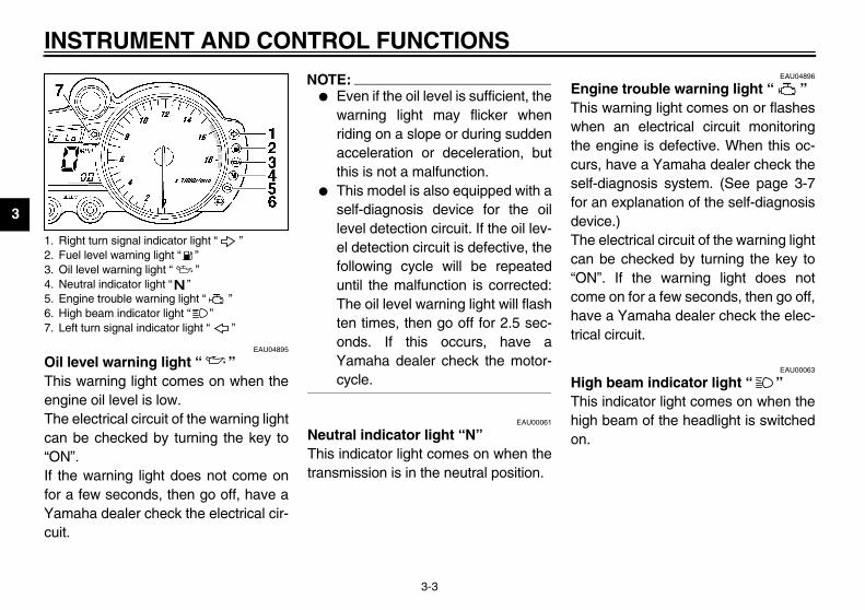
1. Right turn signal indicator light “ ”2. Fuel level warning light “ ”3. Oil level warning light “ ”4. Neutral indicator light “ ”5. Engine trouble warning light “ ”6. High beam indicator light “ ”7. Left turn signal indicator light “ ”
IN
3
OilThiengThecan“ONIf tfor Yacui
EAU04896
ine trouble warning light “ ” s warning light comes on or flashesn an electrical circuit monitoring
engine is defective. When this oc-s, have a Yamaha dealer check the-diagnosis system. (See page 3-7an explanation of the self-diagnosisice.) electrical circuit of the warning light be checked by turning the key to”. If the warning light does note on for a few seconds, then go off,e a Yamaha dealer check the elec-
al circuit.
EAU00063
h beam indicator light “ ” s indicator light comes on when theh beam of the headlight is switched
1. R2. F3. O4. N5. E6. H7. L
U5SL10.book Page 3 Friday, November 1, 2002 4:33 PM
STRUMENT AND CONTROL FUNCTIONS
3-3
EAU04895
level warning light “ ” s warning light comes on when theine oil level is low. electrical circuit of the warning light be checked by turning the key to”.
he warning light does not come ona few seconds, then go off, have amaha dealer check the electrical cir-t.
NOTE:_
� Even if the oil level is sufficient, thewarning light may flicker whenriding on a slope or during suddenacceleration or deceleration, butthis is not a malfunction.
� This model is also equipped with aself-diagnosis device for the oillevel detection circuit. If the oil lev-el detection circuit is defective, thefollowing cycle will be repeateduntil the malfunction is corrected:The oil level warning light will flashten times, then go off for 2.5 sec-onds. If this occurs, have aYamaha dealer check the motor-cycle.
_
EAU00061
Neutral indicator light “N” This indicator light comes on when thetransmission is in the neutral position.
EngThiwhethecurselffor devThecan“ONcomhavtric
HigThihigon.
ight turn signal indicator light “ ”uel level warning light “ ”il level warning light “ ”eutral indicator light “ ”ngine trouble warning light “ ”igh beam indicator light “ ”eft turn signal indicator light “ ”

NTROL FUNCTIONS
3
ShThonspwgeThligto
1.2.3.
U5SL10.book Page 4 Friday, November 1, 2002 4:33 PM
INSTRUMENT AND CO
3-4
EAU04975
ift timing indicator light is indicator light can be set to come and go off at the desired engineeeds and is used to inform the rider
hen it is time to shift to the next higherar.e electrical circuit of the indicatorht can be checked by turning the key “ON”.
If the indicator light does not come onfor a few seconds, then go off, have aYamaha dealer check the electrical cir-cuit. (See pages 3-7–3-10 for a de-tailed explanation of the function of thisindicator light and on how to set it.)
EAU04923*
Coolant temperature warning light“ ” This warning light comes on when theengine overheats. When this occurs,stop the engine immediately and allowthe engine to cool.The electrical circuit of the warning lightcan be checked by turning the key to“ON”.If the warning light does not come onfor a few seconds, then go off, have aYamaha dealer check the electrical cir-cuit.
EC000002
CAUTION:_
Do not operate the engine if it isoverheated. _
Shift timing indicator lightCoolant temperature warning light “ ”Coolant temperature display

IN
3
CB-25
What to do
OK. Go ahead with riding.
OK. Go ahead with riding.
Stop the motorcycle and allow it toidle until the coolant temperaturegoes down.If the temperature does not godown, stop the engine. (See the“Engine overheating” section onpage 6-57 for further instructions.)
Stop the engine and allow it to cool.(See the “Engine overheating” sec-tion on page 6-57 for further in-structions.)
U5SL10.book Page 5 Friday, November 1, 2002 4:33 PM
STRUMENT AND CONTROL FUNCTIONS
3-5
E
Coolant temperature Display Conditions
Under 103 °F(Under 39 °C)
Message “LO” is displayed.
104–242 °F(40–116 °C)
Temperature is displayed.
243–283 °F(117–139 °C)
Temperature flashes.Warning light comes on.
Above 284 °F(Above 140 °C)
Message “HI” flashes.Warning light comes on.
NTROL FUNCTIONS
3
MThw
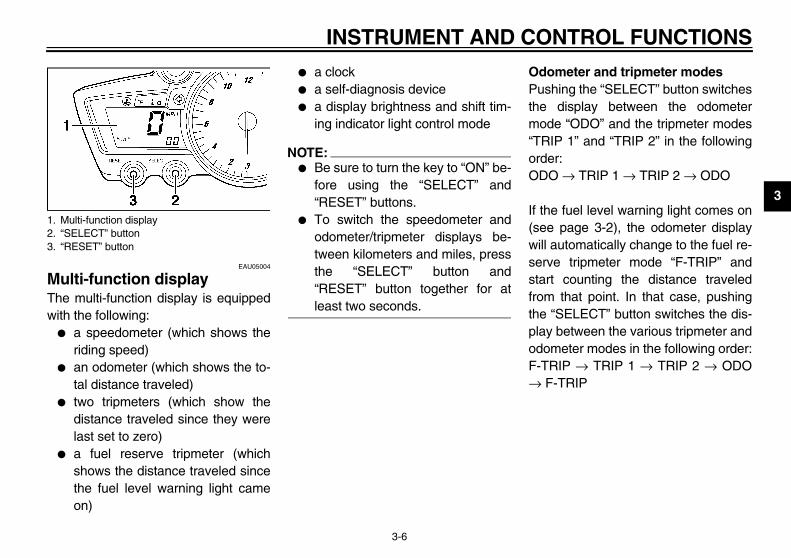
dometer and tripmeter modesshing the “SELECT” button switches
e display between the odometerode “ODO” and the tripmeter modesRIP 1” and “TRIP 2” in the followingder:DO → TRIP 1 → TRIP 2 → ODO
the fuel level warning light comes onee page 3-2), the odometer displayll automatically change to the fuel re-rve tripmeter mode “F-TRIP” andrt counting the distance traveledm that point. In that case, pushing
e “SELECT” button switches the dis-y between the various tripmeter andometer modes in the following order:TRIP → TRIP 1 → TRIP 2 → ODO F-TRIP
1.2.3.
U5SL10.book Page 6 Friday, November 1, 2002 4:33 PM
INSTRUMENT AND CO
3-6
EAU05004
ulti-function display e multi-function display is equipped
ith the following:� a speedometer (which shows the
riding speed)� an odometer (which shows the to-
tal distance traveled)� two tripmeters (which show the
distance traveled since they werelast set to zero)
� a fuel reserve tripmeter (whichshows the distance traveled sincethe fuel level warning light cameon)
� a clock� a self-diagnosis device� a display brightness and shift tim-
ing indicator light control mode
NOTE:_
� Be sure to turn the key to “ON” be-fore using the “SELECT” and“RESET” buttons.
� To switch the speedometer andodometer/tripmeter displays be-tween kilometers and miles, pressthe “SELECT” button and“RESET” button together for atleast two seconds.
_
OPuthm“TorO
If (swisestafrothplaodF-→
Multi-function display “SELECT” button“RESET” button

IN
3
To ingpusoneresitseretuand
CloTurTo moleaTo moTo
1.
2.
3.
play brightness and shift timingicator light control modes mode cycles through five controlctions, allowing you to make the fol-ing settings in the order listed be-.Display brightness: This functionallows you to adjust the brightnessof the multi-function display to suitthe outside lighting conditions.
hift timing indicator lightELECT” buttonESET” button
U5SL10.book Page 7 Friday, November 1, 2002 4:33 PM
STRUMENT AND CONTROL FUNCTIONS
3-7
reset a tripmeter, select it by push- the “SELECT” button, and thenh the “RESET” button for at least second. If you do not reset the fuel
erve tripmeter manually, it will resetlf automatically and the display willrn to the prior mode after refueling traveling 5 km (3 mi).
ck moden the key to “ON”.change the display to the clock
de, push the “SELECT” button for atst one second.change the display back to the priorde, push the “SELECT” button.set the clock:
Push the “SELECT” button and“RESET” button together for atleast two seconds.When the hour digits start flashing,push the “RESET” button to setthe hours.Push the “SELECT” button, andthe minute digits will start flashing.
4. Push the “RESET” button to setthe minutes.
5. Push the “SELECT” button andthen release it to start the clock.
Self-diagnosis devicesThis model is equipped with a self-di-agnosis device for various electrical cir-cuits.If any of those circuits are defective,the engine trouble warning light willcome on, and then the multi-functiondisplay will indicate a two-digit errorcode (e.g., 11, 12, 13).If the multi-function display indicatesany error codes, note the code number,and then have a Yamaha dealer checkthe motorcycle.
ECA00127
CAUTION:_
If the display indicates an errorcode, the motorcycle should bechecked as soon as possible in or-der to avoid engine damage. _
DisindThifunlowlow
1.
1. S2. “S3. “R

NTROL FUNCTIONS
3
2
3
4
5
adjust the display brightness. Turn the key to “OFF”.. Push and hold the “SELECT” but-
ton.. Turn the key to “ON”, and then, af-
ter five seconds, release the“SELECT” button.
. Push the “RESET” button to selectthe desired display brightness lev-el.
. Push the “SELECT” button to con-firm the selected display bright-ness level. The control modechanges to the shift timing indica-tor light activity function.
U5SL10.book Page 8 Friday, November 1, 2002 4:33 PM
INSTRUMENT AND CO
3-8
. Shift timing indicator light activity:This function allows you to choosewhether or not the indicator lightshould be activated and whether itshould blink or stay on when acti-vated.
. Shift timing indicator light activa-tion: This function allows you toselect the engine speed at whichthe indicator light will be activated.
. Shift timing indicator light deacti-vation: This function allows you toselect the engine speed at whichthe indicator light will be deactivat-ed.
. Shift timing indicator light bright-ness: This function allows you toadjust the brightness of the indica-tor light to suit your preference.
NOTE:_
� To make any settings in this mode,you have to cycle through all of itsfunctions. However, if the key isturned to “OFF” or the engine isstarted before completing the pro-cedure, only the settings made be-fore the “SELECT” button was lastpushed will be applied.
� In this mode, the multi-functiondisplay shows the current settingfor each function (except the shifttiming indicator light activity func-tion).
_
To12
3
4
5

IN
3
To tivi
1.
a
b
c
2.
set the shift timing indicator light de-ivation function
TE:The indicator light deactivationfunction can be set between10,000 r/min and 16,000 r/min.From 10,000 r/min to 12,000 r/min,the indicator light can be set in in-crements of 500 r/min. From12,000 r/min to 16,000 r/min, theindicator light can be set in incre-ments of 200 r/min.Be sure to set the deactivationfunction to a higher engine speedthan for the activation function,otherwise the shift timing indicatorlight will remain deactivated.
Push the “RESET” button to selectthe desired engine speed for de-activating the indicator light.Push the “SELECT” button to con-firm the selected engine speed.The control mode changes to theshift timing indicator light bright-ness function.
U5SL10.book Page 9 Friday, November 1, 2002 4:33 PM
STRUMENT AND CONTROL FUNCTIONS
3-9
set the shift timing indicator light ac-ty function
Push the “RESET” button to selectone of the following indicator lightactivity settings:
. The indicator light will stay onwhen activated. (This setting is se-lected when the indicator lightstays on.)
. The indicator light will flash whenactivated. (This setting is selectedwhen the indicator light flashesfour times per second.)
. The indicator light is deactivated;in other words, it will not come onor flash. (This setting is selectedwhen the indicator light flashesonce every two seconds.)Push the “SELECT” button to con-firm the selected indicator light ac-tivity. The control mode changesto the shift timing indicator light ac-tivation function.
To set the shift timing indicator light ac-tivation function
NOTE:_
The shift timing indicator light activationfunction can be set between10,000 r/min and 16,000 r/min. From10,000 r/min to 12,000 r/min, the indi-cator light can be set in increments of500 r/min. From 12,000 r/min to16,000 r/min, the indicator light can beset in increments of 200 r/min. _
1. Push the “RESET” button to selectthe desired engine speed for acti-vating the indicator light.
2. Push the “SELECT” button to con-firm the selected engine speed.The control mode changes to theshift timing indicator light deactiva-tion function.
To act
NO_
�
�
_
1.
2.

NTROL FUNCTIONS
3
Tobr
1
2
EAU00118
andlebar switches
EAU03888
mmer switch “ / ” t this switch to “ ” for the higham and to “ ” for the low beam.
Dimmer switch “ / ”Turn signal switch “ / ”Horn switch “ ”
U5SL10.book Page 10 Friday, November 1, 2002 4:33 PM
INSTRUMENT AND CO
3-10
adjust the shift timing indicator lightightness. Push the “RESET” button to select
the desired indicator light bright-ness level.
. Push the “SELECT” button to con-firm the selected indicator lightbrightness level. The multi-func-tion display will return to the odom-eter, tripmeter or clock mode.
EAU04969
Tachometer The electric tachometer allows the riderto monitor the engine speed and keep itwithin the ideal power range. When the key is turned to “ON”, the ta-chometer needle will move to18,500 r/min and back to zero r/min inorder to test the electrical circuit.
EC000003
CAUTION:_
Do not operate the engine in the ta-chometer red zone.Red zone: 15,500 r/min and above _
H
DiSebe
1. Tachometer2. Tachometer red zone
1.2.3.

IN
3
TuTo swturnreleter lighturn
HoPre
EAU00143
rt switch “ ” h this switch to crank the engine the starter.
EC000005
UTION: page 5-1 for starting instruc-s prior to starting the engine.
1. D2. T3. H
U5SL10.book Page 11 Friday, November 1, 2002 4:33 PM
STRUMENT AND CONTROL FUNCTIONS
3-11
EAU03889
rn signal switch “ / ” signal a right-hand turn, push this
itch to “ ”. To signal a left-hand, push this switch to “ ”. Whenased, the switch returns to the cen-position. To cancel the turn signalts, push the switch in after it has re-ed to the center position.
EAU00129
rn switch “ ” ss this switch to sound the horn.
EAU03890
Engine stop switch “ / ” Set this switch to “ ” before startingthe engine. Set this switch to “ ” tostop the engine in case of an emergen-cy, such as when the motorcycle over-turns or when the throttle cable isstuck.
StaPuswith
CA@
Seetion@
immer switch “ / ”urn signal switch “ / ”orn switch “ ”
1. Engine stop switch “ / ”2. Start switch “ ”

NTROL FUNCTIONS
3
CThhaclbathraclThclcifocu
1.
U5SL10.book Page 12 Friday, November 1, 2002 4:33 PM
INSTRUMENT AND CO
3-12
EAU00152
lutch lever e clutch lever is located at the leftndlebar grip. To disengage the
utch, pull the lever toward the handle-r grip. To engage the clutch, releasee lever. The lever should be pulledpidly and released slowly for smoothutch operation.e clutch lever is equipped with a
utch switch, which is part of the ignitionrcuit cut-off system. (See page 3-24r an explanation of the ignition circuitt-off system.)
EAU00157
Shift pedal The shift pedal is located on the leftside of the engine and is used in com-bination with the clutch lever whenshifting the gears of the 6-speed con-stant-mesh transmission equipped onthis motorcycle.
Clutch lever 1. Shift pedal

IN
3
BrThehanbrabar
EAU00162
ake pedal brake pedal is on the right side of
motorcycle. To apply the rearke, press down on the brake pedal.
1. B rake pedal
U5SL10.book Page 13 Friday, November 1, 2002 4:33 PM
STRUMENT AND CONTROL FUNCTIONS
3-13
EAU00161
ake lever brake lever is located at the rightdlebar grip. To apply the frontke, pull the lever toward the handle- grip.
The brake lever is equipped with a po-sition adjusting dial. To adjust the dis-tance between the brake lever and thehandlebar grip, turn the adjusting dialwhile holding the lever pushed awayfrom the handlebar grip. Make sure thatthe appropriate setting on the adjustingdial is aligned with the arrow mark onthe brake lever.
BrThethebra
rake lever 1. Brake lever position adjusting dial2. Arrow marka. Distance between brake lever and handlebar
grip
1. B
NTROL FUNCTIONS
3
F
ToOseit leop
To1
1.2.
U5SL10.book Page 14 Friday, November 1, 2002 4:33 PM
INSTRUMENT AND CO
3-14
EAU02935
uel tank cap
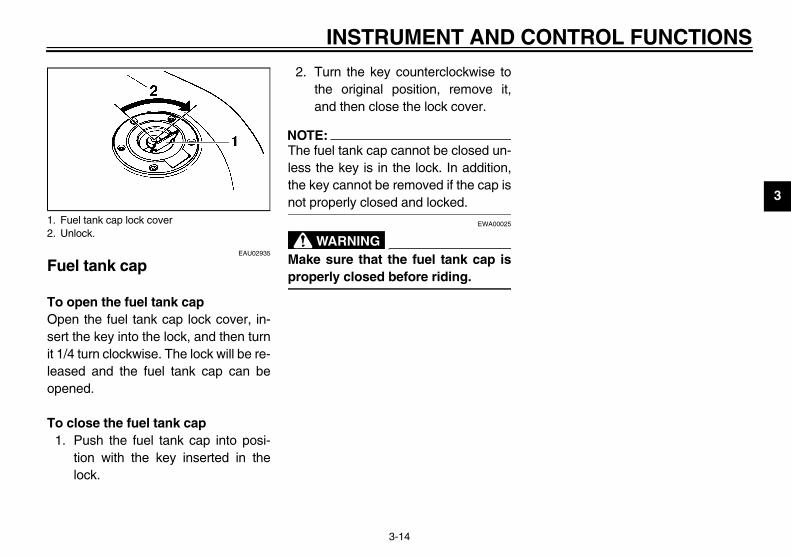
open the fuel tank cappen the fuel tank cap lock cover, in-rt the key into the lock, and then turn
1/4 turn clockwise. The lock will be re-ased and the fuel tank cap can beened.
close the fuel tank cap. Push the fuel tank cap into posi-
tion with the key inserted in thelock.
2. Turn the key counterclockwise tothe original position, remove it,and then close the lock cover.
NOTE:@
The fuel tank cap cannot be closed un-less the key is in the lock. In addition,the key cannot be removed if the cap isnot properly closed and locked. @
EWA00025
WARNING@
Make sure that the fuel tank cap isproperly closed before riding. @
Fuel tank cap lock coverUnlock.

IN
3
FuMatheof t
_
�
�
_
r Yamaha engine has been de-ed to use premium unleaded gaso-
with a pump octane number+M)/2] of 91 or higher, or a researchane number of 95 or higher. Ifcking (or pinging) occurs, use aoline of a different brand. Use of un-ded fuel will extend spark plug life reduce maintenance costs.
soholre are two types of gasohol: gaso-
containing ethanol and that contain- methanol. Gasohol containinganol can be used if the ethanol con-t does not exceed 10%. Gasoholtaining methanol is not recom-nded by Yamaha because it canse damage to the fuel system or ve-e performance problems.
1. F2. F
U5SL10.book Page 15 Friday, November 1, 2002 4:33 PM
STRUMENT AND CONTROL FUNCTIONS
3-15
EAU03753
el ke sure that there is sufficient fuel in tank. Fill the fuel tank to the bottomhe filler tube as shown.
EW000130
WARNINGDo not overfill the fuel tank, oth-erwise it may overflow when thefuel warms up and expands. Avoid spilling fuel on the hotengine.
EAU00185
CAUTION:@
Immediately wipe off spilled fuelwith a clean, dry, soft cloth, sincefuel may deteriorate painted surfac-es or plastic parts. @
EAU04917
ECA00104
CAUTION:_
Use only unleaded gasoline. Theuse of leaded gasoline will cause se-vere damage to internal engineparts, such as the valves and pistonrings, as well as to the exhaust sys-tem. _
Yousignline[(Roctknogasleaand
GaTheholingethtenconmecauhicl
uel tank filler tubeuel level
Recommended fuel:PREMIUM UNLEADED GASOLINE ONLY
Fuel tank capacity:Total amount:
17 L (3.74 Imp gal, 4.49 US gal)Amount remaining when the fuel level warning light comes on:
3.5 L (0.77 Imp gal, 0.92 US gal)

NTROL FUNCTIONS
3
CThalbe
_
Thersyin_
C_
Thobot
_
install the rider seatsert the projection on the front of theer seat into the seat holder asown, place the seat in the originalsition, and then install the bolts.
ProjectionSeat holder
U5SL10.book Page 16 Friday, November 1, 2002 4:33 PM
INSTRUMENT AND CO
3-16
EAU01084
atalytic converter is motorcycle is equipped with a cat-
ytic converter in the exhaust cham-r.
EW000128
WARNINGe exhaust system is hot after op-ation. Make sure that the exhauststem has cooled down before do-g any maintenance work.
EC000114
AUTION:e following precautions must beserved to prevent a fire hazard or
her damages.� Use only unleaded gasoline.
The use of leaded gasoline willcause unrepairable damage tothe catalytic converter.
� Never park the motorcycle nearpossible fire hazards such asgrass or other materials thateasily burn.
� Do not allow the engine to idletoo long.
EAU03814*
Seats
Rider seatTo remove the rider seatPull back the rear of the rider seat asshown, remove the bolts, and then pullthe seat off.
ToInridshpo
1. Bolt (× 2) 1.2.

IN
3
PaTo
1.
2.
EAU04489*
lmet holders helmet holders are located on the
tom of the passenger seat.
secure a helmet to a helmet hold-
Remove the passenger seat.Attach the helmet to a helmetholder, and then securely installthe passenger seat.
1. P2. U
L
elmet holder (× 2)
U5SL10.book Page 17 Friday, November 1, 2002 4:33 PM
STRUMENT AND CONTROL FUNCTIONS
3-17
ssenger seatremove the passenger seat
Insert the key into the seat lock,and then turn it counterclockwise. While holding the key in that posi-tion, lift the front of the passengerseat and pull it forward.
To install the passenger seat1. Insert the projection on the rear of
the passenger seat into the seatholder as shown, and then pushthe front of the seat down to lock itin place.
2. Remove the key.
NOTE:_
Make sure that the seats are properlysecured before riding. _
HeThebot
To er
1.2.
assenger seat locknlock.
eft side
1. Projection2. Seat holder
1. H
NTROL FUNCTIONS
3
_
Na mco_
C_
Sofleheordois_
TohoRthth
U5SL10.book Page 18 Friday, November 1, 2002 4:33 PM
INSTRUMENT AND CO
3-18
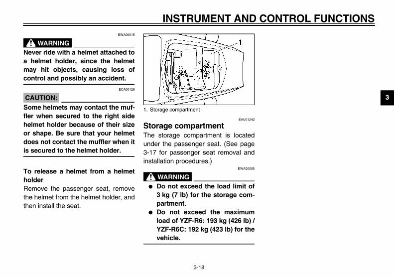
EWA00015
WARNINGever ride with a helmet attached tohelmet holder, since the helmetay hit objects, causing loss ofntrol and possibly an accident.
ECA00128
AUTION:me helmets may contact the muf-r when secured to the right sidelmet holder because of their size shape. Be sure that your helmetes not contact the muffler when it
secured to the helmet holder.
release a helmet from a helmetlder
emove the passenger seat, removee helmet from the helmet holder, anden install the seat.
EAU01242
Storage compartment The storage compartment is locatedunder the passenger seat. (See page3-17 for passenger seat removal andinstallation procedures.)
EWA00005
WARNING_
� Do not exceed the load limit of3 kg (7 lb) for the storage com-partment.
� Do not exceed the maximumload of YZF-R6: 193 kg (426 lb) /YZF-R6C: 192 kg (423 lb) for thevehicle.
_
1. Storage compartment

IN
3
AdThipreingprescr
_
Alwly, of _
TE:n the appropriate groove on the ad-ing mechanism with the top of thet fork cap bolt.
urrent settingront fork cap bolt
Setting
Minimum (soft) 8
Standard 7
Maximum (hard) 1
U5SL10.book Page 19 Friday, November 1, 2002 4:33 PM
STRUMENT AND CONTROL FUNCTIONS
3-19
EAU01862
justing the front fork s front fork is equipped with springload adjusting bolts, rebound damp- force adjusting screws and com-ssion damping force adjustingews.
EW000035
WARNINGays adjust both fork legs equal-
otherwise poor handling and lossstability may result.
Spring preloadTo increase the spring preload andthereby harden the suspension, turnthe adjusting bolt on each fork leg in di-rection a. To decrease the spring pre-load and thereby soften thesuspension, turn the adjusting bolt oneach fork leg in direction b.
NO_
Aligjustfron_
CI-10E
1. Spring preload adjusting bolt 1. C2. F

NTROL FUNCTIONS
3
RTofodaeacrthtuleCI-
EC000015
AUTION:ver attempt to turn an adjusting
echanism beyond the maximum minimum settings.
TE:though the total number of clicks of amping force adjusting mechanismay not exactly match the above spec-ations due to small differences in
oduction, the actual number of clicksays represents the entire adjusting
nge. To obtain a precise adjustment,ould be advisable to check the num-
r of clicks of each damping force ad-ting mechanism and to modify theecifications as necessary.
1.
M
* W
U5SL10.book Page 20 Friday, November 1, 2002 4:33 PM
INSTRUMENT AND CO
3-20
ebound damping force increase the rebound damping
rce and thereby harden the reboundmping, turn the adjusting screw onch fork leg in direction a. To de-ease the rebound damping force andereby soften the rebound damping,rn the adjusting screw on each forkg in direction b.02E
Compression damping forceTo increase the compression dampingforce and thereby harden the compres-sion damping, turn the adjusting screwon each fork leg in direction a. To de-crease the compression damping forceand thereby soften the compressiondamping, turn the adjusting screw oneach fork leg in direction b.CI-02E
C_
Nemor_
NO_
Aldamificpralwrait wbejussp_
Rebound damping force adjusting screw
Minimum (soft) 10 clicks in direction b*
Standard 9 clicks in direction b*
aximum (hard) 1 click in direction b*
ith the adjusting screw fully turned in direction a
1. Compression damping force adjusting screw
Minimum (soft) 9 clicks in direction b*
Standard 7 clicks in direction b*
Maximum (hard) 1 click in direction b*
* With the adjusting screw fully turned in direction a

IN
3
AdasThiequingdam
CA_
Nemeor _
TE:Align the appropriate notch in theadjusting ring with the position in-dicator on the shock absorber. Use the special wrench included inthe owner’s tool kit to make the ad-justment.
Setting
Minimum (soft) 1
Standard 4
Maximum (hard) 9
U5SL10.book Page 21 Friday, November 1, 2002 4:33 PM
STRUMENT AND CONTROL FUNCTIONS
3-21
EAU04496
justing the shock absorber sembly s shock absorber assembly isipped with a spring preload adjust-
ring and rebound and compressionping force adjusting screws.
EC000015
UTION:ver attempt to turn an adjustingchanism beyond the maximumminimum settings.
Spring preloadTo increase the spring preload andthereby harden the suspension, turnthe adjusting ring in direction a. To de-crease the spring preload and therebysoften the suspension, turn the adjust-ing ring in direction b.
NO_
�
�
_
CI-10E
1. Spring preload adjusting ring2. Special wrench3. Position indicator

NTROL FUNCTIONS
3
RTofodaredarescCI-
TE:though the total number of clicks of amping force adjusting mechanismay not exactly match the above spec-ations due to small differences in
oduction, the actual number of clicksays represents the entire adjusting
nge. To obtain a precise adjustment,ould be advisable to check the num-
r of clicks of each damping force ad-ting mechanism and to modify theecifications as necessary.
1.
M
* W
U5SL10.book Page 22 Friday, November 1, 2002 4:33 PM
INSTRUMENT AND CO
3-22
ebound damping force increase the rebound damping
rce and thereby harden the reboundmping, turn the adjusting screw in di-ction a. To decrease the reboundmping force and thereby soften thebound damping, turn the adjustingrew in direction b.
14E
Compression damping forceTo increase the compression dampingforce and thereby harden the compres-sion damping, turn the adjusting screwin direction a. To decrease the com-pression damping force and therebysoften the compression damping, turnthe adjusting screw in direction b.CI-14E
NO_
Aldamificpralwrait wbejussp_
Rebound damping force adjusting screw
Minimum (soft) 20 clicks in direction b*
Standard 10 clicks in direction b*
aximum (hard) 5 clicks in direction b*
ith the adjusting screw fully turned in direction a
1. Compression damping force adjusting screw
Minimum (soft) 20 clicks in direction b*
Standard 10 clicks in direction b*
Maximum (hard) 1 click in direction b*
* With the adjusting screw fully turned in direction a

IN
3
@
Thly prostaforThspoperimp
�
�
�
�
@
EAU00330
estand sidestand is located on the left side
the frame. Raise the sidestand orer it with your foot while holding thetorcycle upright.
TE: built-in sidestand switch is part of
ignition circuit cut-off system, whichs the ignition in certain situations.e further down for an explanation of ignition circuit cut-off system.)
U5SL10.book Page 23 Friday, November 1, 2002 4:33 PM
STRUMENT AND CONTROL FUNCTIONS
3-23
EAU00315
WARNINGis shock absorber contains high-pressurized nitrogen gas. Forper handling, read and under-nd the following information be-e handling the shock absorber.e manufacturer cannot be held re-nsible for property damage orsonal injury that may result fromroper handling.Do not tamper with or attempt toopen the gas cylinder.Do not subject the shock ab-sorber to an open flame or otherhigh heat sources, otherwise itmay explode due to excessivegas pressure.Do not deform or damage thegas cylinder in any way, as thiswill result in poor damping per-formance.Always have a Yamaha dealerservice the shock absorber.
EAU03170
Luggage strap holders There are four luggage strap holderson the bottom of the passenger seat.To use the strap holders, remove thepassenger seat, unhook the straps,and then install the seat with the strapshanging out from under the passengerseat. (See page 3-17 for passengerseat removal and installation proce-dures.)
SidTheof lowmo
NO@
Thethecut(Sethe@
1. Luggage strap holder (× 4)2. Hook (× 4)

NTROL FUNCTIONS
3
@
Thwsimerthtococuasrestchscdepr@
U5SL10.book Page 24 Friday, November 1, 2002 4:33 PM
INSTRUMENT AND CO
3-24
EW000044
WARNINGe motorcycle must not be ridden
ith the sidestand down, or if thedestand cannot be properlyoved up (or does not stay up), oth-wise the sidestand could contacte ground and distract the opera-r, resulting in a possible loss ofntrol. Yamaha’s ignition circuitt-off system has been designed tosist the operator in fulfilling thesponsibility of raising the side-and before starting off. Therefore,eck this system regularly as de-ribed below and have a Yamahaaler repair it if it does not functionoperly.
EAU03720
Ignition circuit cut-off system The ignition circuit cut-off system (com-prising the sidestand switch, clutchswitch and neutral switch) has the fol-lowing functions.
� It prevents starting when the trans-mission is in gear and the side-stand is up, but the clutch lever isnot pulled.
� It prevents starting when the trans-mission is in gear and the clutchlever is pulled, but the sidestand isstill down.
� It cuts the running engine whenthe transmission is in gear and thesidestand is moved down.
Periodically check the operation of theignition circuit cut-off system accordingto the following procedure.
EW000045
WARNING_
If a malfunction is noted, have aYamaha dealer check the systembefore riding. _

IN
3
CD-01E
itch may be defective.le should not be ridden until
Yamaha dealer.
switch may be defective.le should not be ridden until
Yamaha dealer.
itch may be defective.le should not be ridden until
Yamaha dealer.
ost reliable if performed withengine.
U5SL10.book Page 25 Friday, November 1, 2002 4:33 PM
STRUMENT AND CONTROL FUNCTIONS
3-25
With the engine turned off:1. Move the sidestand down.2. Make sure that the engine stop switch is set to “ ”.3. Turn the key to “ON”. 4. Shift the transmission into the neutral position.5. Push the start switch.Does the engine start?
The neutral swThe motorcycchecked by a
With the engine still running:6. Move the sidestand up.7. Keep the clutch lever pulled.8. Shift the transmission into gear.9. Move the sidestand down.Does the engine stall?
After the engine has stalled:10. Move the sidestand up.11. Keep the clutch lever pulled.12. Push the start switch.Does the engine start?
The sidestandThe motorcycchecked by a
The clutch swThe motorcycchecked by a
NO
NOTE:This check is ma warmed-up
YES
YES NO
The system is OK. The motorcycle can be ridden.
YES NO

PRE-OPERATION CHECKS
4
Pre-operation check list ..................................................................... 4-1
U5SL10.book Page 1 Friday, November 1, 2002 4:33 PM
4
EAU01114
teriorate quickly and unexpectedly,). Any damage, fluid leakage or lossddition to a thorough visual inspec-
U5SL10.book Page 1 Friday, November 1, 2002 4:33 PM
4-PR
Theeveof ti
EAU03439
PAGE
3-15
6-14–6-15
6-18–6-20
6-35–6-37
6-34–6-37
6-33
tion
CO-01E
Fu
En
Co
Fro
Re
Clu
4-1
E-OPERATION CHECKS
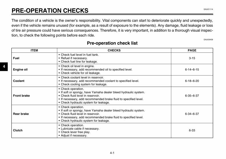
condition of a vehicle is the owner’s responsibility. Vital components can start to den if the vehicle remains unused (for example, as a result of exposure to the elementsre air pressure could have serious consequences. Therefore, it is very important, in a, to check the following points before each ride.
Pre-operation check list ITEM CHECKS
el• Check fuel level in fuel tank.• Refuel if necessary.• Check fuel line for leakage.
gine oil• Check oil level in engine.• If necessary, add recommended oil to specified level.• Check vehicle for oil leakage.
olant• Check coolant level in reservoir.• If necessary, add recommended coolant to specified level.• Check cooling system for leakage.
nt brake
• Check operation.• If soft or spongy, have Yamaha dealer bleed hydraulic system.• Check fluid level in reservoir.• If necessary, add recommended brake fluid to specified level.• Check hydraulic system for leakage.
ar brake
• Check operation.• If soft or spongy, have Yamaha dealer bleed hydraulic system.• Check fluid level in reservoir.• If necessary, add recommended brake fluid to specified level.• Check hydraulic system for leakage.
tch
• Check operation.• Lubricate cable if necessary.• Check lever free play.• Adjust if necessary.

PERATION CHECKS
4
T te cable and 6-28, 6-40
C 6-39
D 6-37–6-39
W 6-29–6-32
B 6-41
B 6-40
S 6-41
C —
Ina —
S 3-25
A 6-27
PAGE
U5SL10.book Page 2 Friday, November 1, 2002 4:33 PM
PRE-O
4-2
hrottle grip
• Make sure that operation is smooth.• Check cable free play.• If necessary, have Yamaha dealer adjust cable free play and lubrica
grip housing.
ontrol cables • Make sure that operation is smooth.• Lubricate if necessary.
rive chain
• Check chain slack.• Adjust if necessary.• Check chain condition.• Lubricate if necessary.
heels and tires
• Check for damage.• Check tire condition and tread depth.• Check air pressure.• Correct if necessary.
rake and shift pedals • Make sure that operation is smooth.• Lubricate pedal pivoting points if necessary.
rake and clutch levers • Make sure that operation is smooth.• Lubricate lever pivoting points if necessary.
idestand • Make sure that operation is smooth.• Lubricate pivot if necessary.
hassis fasteners • Make sure that all nuts, bolts and screws are properly tightened.• Tighten if necessary.
struments, lights, signals nd switches
• Check operation. • Correct if necessary.
idestand switch • Check operation of ignition circuit cut-off system.• If system is defective, have Yamaha dealer check vehicle.
ir intake duct • Check that the screen is not clogged.• Clean if necessary.
ITEM CHECKS

PR
4
NO@
Pre ction can be accomplished in a verysho@
EWA00033
@
If a ed and repaired before operatingthe@
U5SL10.book Page 3 Friday, November 1, 2002 4:33 PM
E-OPERATION CHECKS
4-3
TE:-operation checks should be made each time the motorcycle is used. Such an inspert time; and the added safety it assures is more than worth the time involved.
WARNINGny item in the Pre-operation check list is not working properly, have it inspect motorcycle.
OPERATION AND IMPORTANT RIDING POINTS
5
Starting the engine ............................................................................ 5-1Shifting .............................................................................................. 5-3Engine break-in ................................................................................. 5-4Parking .............................................................................................. 5-5
U5SL10.book Page 1 Friday, November 1, 2002 4:33 PM

5
EAU00372
EAU05006
rting the engine order for the ignition circuit cut-off
U5SL10.book Page 1 Friday, November 1, 2002 4:33 PM
5-OP
@
�
tem to enable starting, one of thewing conditions must be met:The transmission is in the neutralposition.The transmission is in gear withthe clutch lever pulled and thesidestand up.
EW000054
WARNINGBefore starting the engine,check the function of the igni-tion circuit cut-off system ac-cording to the proceduredescribed on page 3-25. Never ride with the sidestanddown.
Turn the key to “ON” and makesure that the engine stop switch isset to “ ”.
�
�
@
5-1
ERATION AND IMPORTANT RIDING POINTSEAU00373
WARNINGBecome thoroughly familiarwith all operating controls andtheir functions before riding.Consult a Yamaha dealer re-garding any control or functionthat you do not thoroughly un-derstand.Never start the engine or oper-ate it in a closed area for anylength of time. Exhaust fumesare poisonous, and inhalingthem can cause loss of con-sciousness and death within ashort time. Always make surethat there is adequateventilation.Before starting out, make surethat the sidestand is up. If thesidestand is not raised com-pletely, it could contact theground and distract the opera-tor, resulting in a possible lossof control.
EAU00376
CAUTION:_
� Make sure not to store personalitems near the air cleaner in-take, otherwise air intake will beblocked and performance willsuffer.
� Make sure not to put anythingnear the battery and its termi-nals, otherwise electrical failureand acid corrosion may result.
_
StaIn sysfollo
�
�
_
�
�
_
1.

ANT RIDING POINTS
5
C_
Thdife
If nocoto_
2
N_
WposhYacu_
U5SL10.book Page 2 Friday, November 1, 2002 4:33 PM
OPERATION AND IMPORT
5-2
ECA00152
AUTION:e following warning lights and in-
cator light should come on for aw seconds, then go off.� Oil level warning light� Fuel level warning light� Coolant temperature warning
light� Shift timing indicator light� Engine trouble warning lighta warning or indicator light doest go off, see pages 3-2–3-5 for therresponding warning and indica-r light circuit check.
. Shift the transmission into the neu-tral position.
OTE:hen the transmission is in the neutralsition, the neutral indicator lightould be on, otherwise have amaha dealer check the electrical cir-it.
3. Start the engine by pushing thestart switch.
NOTE:_
If the engine fails to start, release thestart switch, wait a few seconds, andthen try again. Each starting attemptshould be as short as possible to pre-serve the battery. Do not crank the en-gine more than 10 seconds on any oneattempt. _
ECA00055
CAUTION:_
For maximum engine life, alwayswarm the engine up before startingoff. Never accelerate hard when theengine is cold! _
NOTE:_
The engine is warm when it quickly re-sponds to the throttle. _

O
5 ShShamstaetcTheillu
NO@
To tralreptrav@
EAU02988
start out and accelerate Pull the clutch lever to disengagethe clutch.Shift the transmission into firstgear. The neutral indicator lightshould go out.Open the throttle gradually, and atthe same time, release the clutchlever slowly.At the recommended shift pointsshown in the table on page 5-4,close the throttle, and at the sametime, quickly pull the clutch leverin.Shift the transmission into secondgear. (Make sure not to shift thetransmission into the neutral posi-tion.)Open the throttle part way andgradually release the clutch lever.Follow the same procedure whenshifting to the next higher gear.
TE:ays shift gears at the recommend-shift points.
1. SN. N
U5SL10.book Page 3 Friday, November 1, 2002 4:33 PM
PERATION AND IMPORTANT RIDING POINTS
5-3
EAU00423
ifting ifting gears lets you control theount of engine power available forrting off, accelerating, climbing hills,. gear positions are shown in the
stration.
TE:shift the transmission into the neu- position, press the shift pedal downeatedly until it reaches the end of itsel, and then slightly raise it.
EC000048
CAUTION:@
� Even with the transmission inthe neutral position, do notcoast for long periods of timewith the engine off, and do nottow the motorcycle for long dis-tances. The transmission isproperly lubricated only whenthe engine is running. Inade-quate lubrication may damagethe transmission.
� Always use the clutch whilechanging gears to avoid dam-aging the engine, transmission,and drive train, which are notdesigned to withstand theshock of forced shifting.
@
To 1.
2.
3.
4.
5.
6.
7.
NO_
Alwed _
hift pedaleutral position
ANT RIDING POINTS
5
To1
2
3
EAU01128
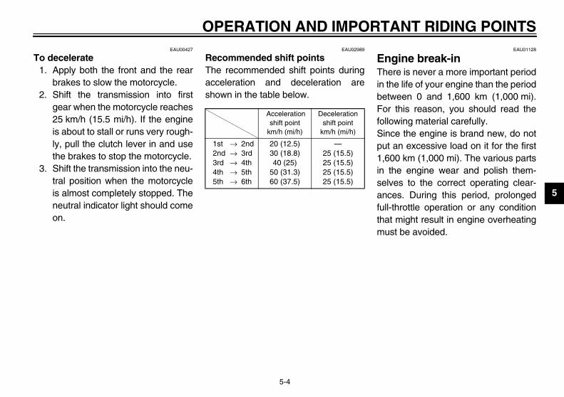
ngine break-in ere is never a more important periodthe life of your engine than the periodtween 0 and 1,600 km (1,000 mi).r this reason, you should read the
llowing material carefully.nce the engine is brand new, do nott an excessive load on it for the first
600 km (1,000 mi). The various partsthe engine wear and polish them-lves to the correct operating clear-ces. During this period, prolonged
ll-throttle operation or any conditionat might result in engine overheatingust be avoided.
U5SL10.book Page 4 Friday, November 1, 2002 4:33 PM
OPERATION AND IMPORT
5-4
EAU00427
decelerate . Apply both the front and the rear
brakes to slow the motorcycle.. Shift the transmission into first
gear when the motorcycle reaches25 km/h (15.5 mi/h). If the engineis about to stall or runs very rough-ly, pull the clutch lever in and usethe brakes to stop the motorcycle.
. Shift the transmission into the neu-tral position when the motorcycleis almost completely stopped. Theneutral indicator light should comeon.
EAU02989
Recommended shift points The recommended shift points duringacceleration and deceleration areshown in the table below.CF-05E
EThin beFofoSipu1,in seanfuthm
Accelerationshift point
km/h (mi/h)
Decelerationshift point
km/h (mi/h)
1st → 2nd2nd → 3rd3rd → 4th4th → 5th5th → 6th
20 (12.5)30 (18.8)40 (25)
50 (31.3)60 (37.5)
—25 (15.5)25 (15.5)25 (15.5)25 (15.5)

O
5
0–1Avo7,0
1,0Avo9,0
CA_
Aftthethe_
1,6Thema
CA_
�
�
_
U5SL10.book Page 5 Friday, November 1, 2002 4:33 PM
PERATION AND IMPORTANT RIDING POINTS
5-5
EAU03749*
,000 km (0–600 mi)id prolonged operation above
00 r/min.
00–1,600 km (600–1,000 mi)id prolonged operation above
00 r/min.EC000052*
UTION:er 1,000 km (600 mi) of operation, engine oil must be changed and oil filter cartridge replaced.
00 km (1,000 mi) and beyond vehicle can now be operated nor-
lly.EC000053
UTION:Keep the engine speed out ofthe tachometer red zone.If any engine trouble should oc-cur during the engine break-inperiod, immediately have aYamaha dealer check the vehi-cle.
EAU00461
Parking When parking, stop the engine, andthen remove the key from the mainswitch.
EW000058
WARNING_
� Since the engine and exhaustsystem can become very hot,park in a place where pedestri-ans or children are not likely totouch them.
� Do not park on a slope or onsoft ground, otherwise themotorcycle may overturn.
_
EC000062
CAUTION:_
Never park in an area where thereare fire hazards such as grass orother flammable materials. _
6
PERIODIC MAINTENANCE AND MINOR REPAIR
Periodic maintenance ..........................................6-1Owner’s tool kit ....................................................6-1Periodic maintenance chart for the emission
control system ...................................................6-3General maintenance and lubrication chart .........6-5Removing and installing cowlings and panels .....6-9Checking the spark plugs ..................................6-12Canister (for California only) ..............................6-13Engine oil and oil filter cartridge ........................6-14Coolant ..............................................................6-18Checking the air filter element ...........................6-24Air intake duct ....................................................6-27Adjusting the throttle cable free play ..................6-28Adjusting the valve clearance ............................6-28Tires ...................................................................6-29Cast wheels .......................................................6-32Accessories and replacement parts ..................6-32Adjusting the clutch lever free play ....................6-33Adjusting the brake pedal position .....................6-34Adjusting the rear brake light switch ..................6-34Checking the front and rear brake pads .............6-35Checking the brake fluid level ............................6-36Changing the brake fluid ....................................6-37Drive chain slack ................................................6-37
Lubricating the drive chain ................................ 6-39Checking and lubricating the cables ................. 6-39Checking and lubricating the throttle grip and
cable ............................................................... 6-40Checking and lubricating the brake and
clutch levers .................................................... 6-40Checking and lubricating the brake and
shift pedals ...................................................... 6-41Checking and lubricating the sidestand ............ 6-41Lubricating the swingarm pivot .......................... 6-42Checking the front fork ...................................... 6-42Checking the steering ....................................... 6-43Checking the wheel bearings ............................ 6-43Battery ............................................................... 6-44Replacing the fuses .......................................... 6-45Replacing a headlight bulb ................................ 6-46Tail/brake light ................................................... 6-48Replacing a turn signal light bulb ...................... 6-48Replacing the license plate light bulb ................ 6-49Supporting the motorcycle ................................ 6-49Front wheel ....................................................... 6-50Rear wheel ........................................................ 6-53Troubleshooting ................................................. 6-55Troubleshooting charts ...................................... 6-56
U5SL10.book Page 1 Friday, November 1, 2002 4:33 PM

6
EAU00462
U5SL10.book Page 1 Friday, November 1, 2002 4:33 PM
6-PE
SafPer
EAU04266
ner’s tool kit owner’s tool kit is located inside
storage compartment under thesenger seat. (See page 3-17 forsenger seat removal and installa- procedures.) service information included in this
nual and the tools provided in theer’s tool kit are intended to assist in the performance of preventiveintenance and minor repairs. How-r, additional tools such as a torquench may be necessary to performtain maintenance work correctly.
wner’s tool kit
bricsafesiblmolubring Maof tsysreptha
_
If ycycYam_
6-1
RIODIC MAINTENANCE AND MINOR REPAIR EAU01790
ety is an obligation of the owner.iodic inspection, adjustment and lu-ation will keep your vehicle in thest and most efficient condition pos-
e. The most important points oftorcycle inspection, adjustment, andication are explained on the follow-pages.intenance, replacement, or repairhe emission control devices andtems may be performed by anyair establishment or individualt is certified (if applicable).
EW000060
WARNINGou are not familiar with motor-le maintenance work, have aaha dealer do it for you.
EAU00467
PERIODIC MAINTENANCE PROPER PERIODIC MAINTENANCEOF YOUR MOTORCYCLE IS IMPOR-TANT IN ORDER TO ENJOY LONG,PLEASURABLE SERVICE. ESPE-CIALLY IMPORTANT ARE THEMAINTENANCE SERVICES RELAT-ED TO EMISSIONS CONTROL.THESE CONTROLS NOT ONLYFUNCTION TO ENSURE CLEANERAIR, BUT ARE ALSO VITAL TOPROPER ENGINE OPERATION ANDMAXIMUM PERFORMANCE. IN THEFOLLOWING PERIODIC MAINTE-NANCE CHARTS, THE SERVICESRELATED TO EMISSIONS CON-TROL ARE GROUPED SEPARATE-LY. THESE SERVICES REQUIRESPECIALIZED DATA, KNOWLEDGE,AND EQUIPMENT. YAMAHA DEAL-ERS ARE TRAINED AND EQUIPPEDTO PERFORM THESE PARTICULARSERVICES.
OwThethepaspastionThemaownyoumaevewrecer
1. O

AND MINOR REPAIR
6
N_
If ena _
_
MYamreCte_
U5SL10.book Page 2 Friday, November 1, 2002 4:33 PM
PERIODIC MAINTENANCE
6-2
OTE:you do not have the tools or experi-ce required for a particular job, have
Yamaha dealer perform it for you.
EW000062
WARNINGodifications not approved bymaha may cause loss of perfor-
ance, excessive emissions, andnder the vehicle unsafe for use.onsult a Yamaha dealer before at-mpting any changes.

PE
6
EAU00471
ol system
No
OMETER READINGSim)
hs
12,000 mi(19,000 km)
or18 months
16,000 mi(25,000 km)
or24 months
20,000 mi(31,000 km)
or30 months
1 00 mi (42,000 km)
2 e. √ Replace. √
3 √ √ √
4 √ √ √
5 √ √ √
6 √ √ √
7 √
* S e.** C
U5SL10.book Page 3 Friday, November 1, 2002 4:33 PM
RIODIC MAINTENANCE AND MINOR REPAIR
6-3
Periodic maintenance chart for the emission contr
. ITEM ROUTINE
INITIAL OD600 mi
(1,000 km)or
1 month
4,000mi(7,000 km)
or6 months
8,000 m(13,000 k
or12 mont
* Valve clearance • Check and adjust valve clearance when engine is cold. Every 26,6
* Spark plugs
• Check condition. • Adjust gap and clean. • Replace every 8,000 mi (13,000 km)
or 12 months.
√ Replac
*Crankcase ventilation system
• Check ventilation hose for cracks or damage.
• Replace if necessary.√ √
* Fuel line• Check fuel hoses for cracks or
damage.• Replace if necessary.
√ √
* Exhaust system• Check for leakage. • Tighten if necessary. • Replace gasket(s) if necessary.
√ √
*Electronic fuel injection
• Check and adjust engine idle speed and synchronization. √ √ √
*Evaporative emission control system**
• Check control system for damage. • Replace if necessary.
ince these items require special tools, data and technical skills, have a Yamaha dealer perform the servicalifornia only

AND MINOR REPAIR
6
8 √
N
DOMETER READINGSmi km)
ths
12,000 mi(19,000 km)
or18 months
16,000 mi(25,000 km)
or24 months
20,000 mi(31,000 km)
or30 months
* ice.**
U5SL10.book Page 4 Friday, November 1, 2002 4:33 PM
PERIODIC MAINTENANCE
6-4
*Air induction system
• Check the air cut-off valve, reed valve, and hose for damage.
• Replace any damaged parts.√
o. ITEM ROUTINE
INITIAL O600 mi
(1,000 km)or
1 month
4,000mi(7,000 km)
or6 months
8,000 (13,000
or12 mon
Since these items require special tools, data and technical skills, have a Yamaha dealer perform the servCalifornia only

PE
6
EAU00472
rt
No
OMETER READINGSim)
hs
12,000 mi(19,000 km)
or18 months
16,000 mi(25,000 km)
or24 months
20,000 mi(31,000 km)
or30 months
1 √ √ √
2 √
3 √ √ √
4√ √ √
Replace.
5 √ √ √
6 √ √ √
7 √ √ √
8 √Repack.
* S e.
U5SL10.book Page 5 Friday, November 1, 2002 4:33 PM
RIODIC MAINTENANCE AND MINOR REPAIR
6-5
General maintenance and lubrication cha
. ITEM ROUTINE
INITIAL OD600 mi
(1,000 km)or
1 month
4,000mi(7,000 km)
or6 months
8,000 m(13,000 k
or12 mont
Engine oil• Replace (warm engine before
draining). (See page 8-1.)√ √ √
*Engine oil filter cartridge
• Replace at initial 600 mi (1,000 km) or 1 month, and thereafter every 8,000 mi (13,000 km) or 12 months.
√ √
* Air filter element• Check condition and damage.• Replace if necessary.
√ √
* Cooling system
• Check hoses for cracks or damage.• Replace if necessary.
√ √
• Replace with ethylene glycol anti-freeze coolant every 24 months.
* Brake system• Check operation, pad wear, and fluid
leakage. (See NOTE on page 6-8.)• Correct if necessary.
√ √ √
* Clutch• Check operation.• Adjust or replace cable.
√ √ √
* Control cables• Apply Yamaha chain and cable lube or
engine oil 10W-30 thoroughly.√ √ √
*Swingarm pivot bearing
• Check bearing assembly for looseness.
• Moderately repack with lithium-soap-based grease every 16,000 mi (25,000 km) or 24 months.
√
ince these items require special tools, data and technical skills, have a Yamaha dealer perform the servic

AND MINOR REPAIR
6
9 √
10 √ √ √
11 √ √ √
12 √ √Repack. √
13 √ √ √
14 √ √ √
15or after washing the motorcycle ing in the rain.
16 √ √ √
17 √ √ √
18 √ √ √
N
DOMETER READINGSmi km)
ths
12,000 mi(19,000 km)
or18 months
16,000 mi(25,000 km)
or24 months
20,000 mi(31,000 km)
or30 months
* ice.
U5SL10.book Page 6 Friday, November 1, 2002 4:33 PM
PERIODIC MAINTENANCE
6-6
*Rear suspension link pivots
• Check operation.• Correct if necessary.
√
*Shock absorber assembly
• Check operation and for oil leakage.• Replace if necessary.
√ √
* Front fork• Check operation and oil leakage.• Replace if necessary.
√ √
* Steering bearings
• Check bearing assembly for looseness.
• Moderately repack with lithium-soap-based grease every 16,000 mi (25,000 km) or 24 months.
√ √ √
Brake and clutch lever pivot shafts
• Apply lithium-soap-based grease (all-purpose grease) lightly.
√ √
Brake and shift pedal pivot shafts
• Apply lithium-soap-based grease (all-purpose grease) lightly.
√ √
Drive chain
• Check chain slack/alignment and condition.
• Adjust and lubricate chain with a special O-ring chain lubricant thoroughly.
Every 500 mi (800 km) or rid
* Wheel bearings • Check bearings for smooth operation. √ √
Sidestand pivot• Check operation and lubricate.• Apply lithium-soap-based grease (all-
purpose grease) lightly.√ √
* Sidestand switch• Check operation and replace if
necessary.√ √ √
o. ITEM ROUTINE
INITIAL O600 mi
(1,000 km)or
1 month
4,000mi(7,000 km)
or6 months
8,000 (13,000
or12 mon
Since these items require special tools, data and technical skills, have a Yamaha dealer perform the serv

PE
6
19 √ √ √
20√ √ √
ry 4 years
21 √ √ √
22 √ √ √
No
OMETER READINGSim)
hs
12,000 mi(19,000 km)
or18 months
16,000 mi(25,000 km)
or24 months
20,000 mi(31,000 km)
or30 months
* S e.
U5SL10.book Page 7 Friday, November 1, 2002 4:33 PM
RIODIC MAINTENANCE AND MINOR REPAIR
6-7
* Chassis fasteners• Check all chassis fitting and fasteners.• Correct if necessary.
√ √
* Brake hoses• Check for cracks or damage. √ √• Replace. (See NOTE on page 6-8.) Eve
* Wheels• Check runout and for damage.• Replace if necessary.
√ √
* Tires
• Check tread depth and for damage.• Replace if necessary.• Check air pressure.• Correct if necessary.
√ √
. ITEM ROUTINE
INITIAL OD600 mi
(1,000 km)or
1 month
4,000mi(7,000 km)
or6 months
8,000 m(13,000 k
or12 mont
ince these items require special tools, data and technical skills, have a Yamaha dealer perform the servic

AND MINOR REPAIR
6
EAU03907
N_
Fr om 4,000 mi (7,000 km) or 6 months. _
EAU04249
N_
y areas.
fluid. Regularly check the brake fluid
and calipers, and change the brake
_
U5SL10.book Page 8 Friday, November 1, 2002 4:33 PM
PERIODIC MAINTENANCE
6-8
OTE:om 24,000 mi (37,000 km) or 36 months, repeat the maintenance intervals starting fr
OTE:� The air filter needs more frequent service if you are riding in unusually wet or dust� Hydraulic brake service
• After disassembling the brake master cylinders and calipers, always change thelevels and fill the reservoirs as required.
• Every two years replace the internal components of the brake master cylindersfluid.
• Replace the brake hoses every four years and if cracked or damaged.

PE
6
RecoTheneeof thistimmo
EAU04959
wlings A and Bremove one of the cowlings
ove the bolts, slide the cowling for-d (for A) or backward (for B), andn pull it off as shown.
1. C2. P
olt (× 3)
r Cowling A
U5SL10.book Page 9 Friday, November 1, 2002 4:33 PM
RIODIC MAINTENANCE AND MINOR REPAIR
6-9
EAU01139
moving and installing wlings and panels cowlings and panels shown aboved to be removed to perform some
the maintenance jobs described in chapter. Refer to this section eache a cowling or panel needs to be re-ved and installed.
CoTo Remwarthe
owling Aanel A
1. Cowling B2. Panel B
1. B
Fo

AND MINOR REPAIR
6
1.2.
R
Cowling ACowling B
U5SL10.book Page 10 Friday, November 1, 2002 4:33 PM
PERIODIC MAINTENANCE
6-10
Bolt (× 8)Cowling A
ight side
1. Bolt (× 8)2. Cowling B
Left side
1.2.

PE
6
To 1.
2.
EAU04955
els A and Bremove one of the panels
ove the bolts, slide the panel for-d, and then take it off.
1. S2. P
olt (× 2)
U5SL10.book Page 11 Friday, November 1, 2002 4:33 PM
RIODIC MAINTENANCE AND MINOR REPAIR
6-11
install the cowlingFit the slots and projections at therear bottom of each cowling to-gether, and then slide the cowlinginto place.Place the cowling in the originalposition, and then install the bolts.
NOTE:_
Make sure that the tabs at the front ofeach cowling fit side by side as shownand that all slots and projections fit to-gether. _
PanTo Remwar
lot (× 2)rojection (× 2)
1. Tab (× 2) 1. B
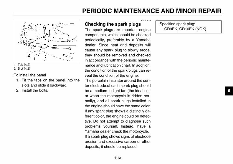
AND MINOR REPAIR
6
To1
2
1.2.
Specified spark plug:CR9EK, CR10EK (NGK)
U5SL10.book Page 12 Friday, November 1, 2002 4:33 PM
PERIODIC MAINTENANCE
6-12
install the panel. Fit the tabs on the panel into the
slots and slide it backward.. Install the bolts.
EAU01639
Checking the spark plugs The spark plugs are important enginecomponents, which should be checkedperiodically, preferably by a Yamahadealer. Since heat and deposits willcause any spark plug to slowly erode,they should be removed and checkedin accordance with the periodic mainte-nance and lubrication chart. In addition,the condition of the spark plugs can re-veal the condition of the engine.The porcelain insulator around the cen-ter electrode of each spark plug shouldbe a medium-to-light tan (the ideal col-or when the motorcycle is ridden nor-mally), and all spark plugs installed inthe engine should have the same color.If any spark plug shows a distinctly dif-ferent color, the engine could be defec-tive. Do not attempt to diagnose suchproblems yourself. Instead, have aYamaha dealer check the motorcycle.If a spark plug shows signs of electrodeerosion and excessive carbon or otherdeposits, it should be replaced.
Tab (× 2)Slot (× 2)
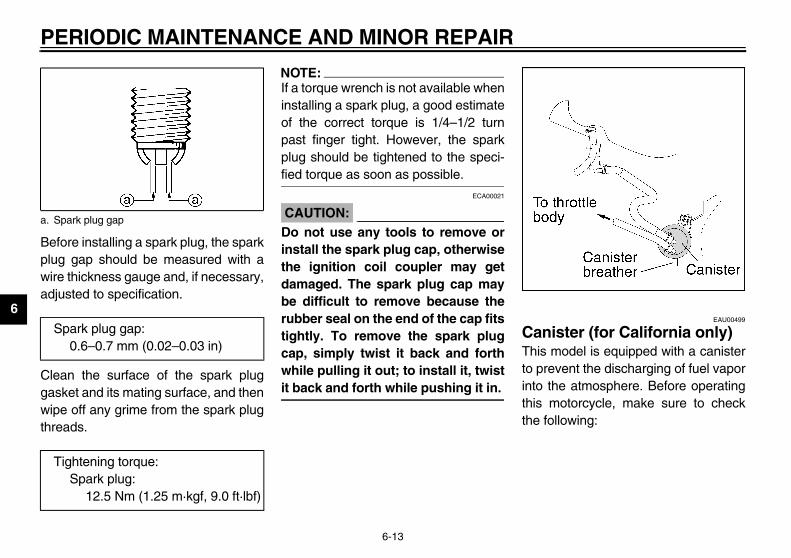
PE
6
Bepluwiradj
Clegaswipthre
EAU00499
nister (for California only) s model is equipped with a canisterrevent the discharging of fuel vapor the atmosphere. Before operating motorcycle, make sure to check following:
a. S
S
T
U5SL10.book Page 13 Friday, November 1, 2002 4:33 PM
RIODIC MAINTENANCE AND MINOR REPAIR
6-13
fore installing a spark plug, the sparkg gap should be measured with ae thickness gauge and, if necessary,usted to specification.
an the surface of the spark plugket and its mating surface, and thene off any grime from the spark plugads.
NOTE:_
If a torque wrench is not available wheninstalling a spark plug, a good estimateof the correct torque is 1/4–1/2 turnpast finger tight. However, the sparkplug should be tightened to the speci-fied torque as soon as possible. _
ECA00021
CAUTION:_
Do not use any tools to remove orinstall the spark plug cap, otherwisethe ignition coil coupler may getdamaged. The spark plug cap maybe difficult to remove because therubber seal on the end of the cap fitstightly. To remove the spark plugcap, simply twist it back and forthwhile pulling it out; to install it, twistit back and forth while pushing it in. _
CaThito pintothisthe
park plug gap
park plug gap:0.6–0.7 mm (0.02–0.03 in)
ightening torque:Spark plug:
12.5 Nm (1.25 m·kgf, 9.0 ft·lbf)

AND MINOR REPAIR
6
. Remove the engine oil dipstickand wipe it clean, insert it back intothe hole (without screwing it in),and then remove it again to checkthe oil level.
TE:e engine oil should be between the
inimum and maximum level marks.
Engine oil dipstickMaximum level markMinimum level mark
ight side
U5SL10.book Page 14 Friday, November 1, 2002 4:33 PM
PERIODIC MAINTENANCE
6-14
� Check each hose connection.� Check each hose and canister for
cracks or damage. Replace ifdamaged.
� Make sure that the canisterbreather is not blocked, and if nec-essary, clean it.
EAU04941
Engine oil and oil filter cartridge The engine oil level should be checkedbefore each ride. In addition, the oilmust be changed and the oil filter car-tridge replaced at the intervals speci-fied in the periodic maintenance andlubrication chart.
To check the engine oil level1. Place the motorcycle on a level
surface and hold it in an uprightposition.
NOTE:_
Make sure that the motorcycle is posi-tioned straight up when checking the oillevel. A slight tilt to the side can result ina false reading. _
2. Start the engine, warm it up forseveral minutes, and then turn itoff.
3. Wait a few minutes until the oil set-tles.
4
NO_
Thm_
1.2.3.
R

PE
6
5.
6.
Remove the engine oil filler capand drain bolt to drain the oil fromthe crankcase.
TE:p steps 4–10 if the oil filter cartridgeot being replaced.
1. E ngine oil drain bolt
ft side
U5SL10.book Page 15 Friday, November 1, 2002 4:33 PM
RIODIC MAINTENANCE AND MINOR REPAIR
6-15
If the engine oil is at or below theminimum level mark, remove theoil filler cap, and then add suffi-cient oil of the recommended typeto raise it to the correct level.Insert and tighten the engine oildipstick, and then install and tight-en the oil filler cap.
To change the engine oil (with orwithout oil filter cartridge replace-ment)
1. Start the engine, warm it up forseveral minutes, and then turn itoff.
2. Place an oil pan under the engineto collect the used oil.
3.
NO_
Skiis n_
ngine oil filler cap 1. E
Le

AND MINOR REPAIR
6
4
5
. Apply a thin coat of engine oil tothe O-ring of the new oil filter car-tridge.
TE:ake sure that the O-ring is properlyated.
1.2.
O-ring
U5SL10.book Page 16 Friday, November 1, 2002 4:33 PM
PERIODIC MAINTENANCE
6-16
. Remove the coolant reservoir cov-er by removing the bolts.
. Remove cowling B. (See page 6-9for cowling removal and installa-tion procedures.)
6. Remove the oil filter cartridge withan oil filter wrench.
NOTE:_
An oil filter wrench is available at aYamaha dealer. _
7
NO_
Mse_
Coolant reservoir coverBolt (× 2)
1. Oil filter wrench2. Oil filter cartridge
1.

PE
6
8.
9.10.
11.
ECA00133
UTION:In order to prevent clutch slip-page (since the engine oil alsolubricates the clutch), do notmix any chemical additives. Donot use oils with a diesel speci-fication of “CD” or oils of ahigher quality than specified. Inaddition, do not use oils labeled“ENERGY CONSERVING II” orhigher.Make sure that no foreign mate-rial enters the crankcase.
Start the engine, and then let it idlefor several minutes while checkingit for oil leakage. If oil is leaking,immediately turn the engine offand check for the cause.
TE:r the engine is started, the engine
evel warning light should go off if theevel is sufficient.
1. T
T
U5SL10.book Page 17 Friday, November 1, 2002 4:33 PM
RIODIC MAINTENANCE AND MINOR REPAIR
6-17
Install the new oil filter cartridgewith an oil filter wrench, and thentighten it to the specified torquewith a torque wrench.
Install the cowling.Install the coolant reservoir coverby installing the bolts.Install the engine oil drain bolt, andthen tighten it to the specifiedtorque.
NOTE:_
Check the washer for damage and re-place it if necessary. _
12. Add the specified amount of therecommended engine oil, andthen install and tighten the oil fillercap.
CA_
�
�
_
13.
NO_
Afteoil loil l_
orque wrench
ightening torque:Oil filter cartridge:
17 Nm (1.7 m·kgf, 12 ft·lbf)
Tightening torque:Engine oil drain bolt:
43 Nm (4.3 m·kgf, 31 ft·lbf)
Recommended engine oil:See page 8-1.
Oil quantity:Without oil filter cartridge replacement:
2.4 L (2.11 Imp qt, 2.54 US qt)With oil filter cartridge replacement:
2.6 L (2.29 Imp qt, 2.75 US qt)Total amount (dry engine):
3.4 L (2.99 Imp qt, 3.59 US qt)

AND MINOR REPAIR
6
C_
If orener_
14
. Check the coolant level in thecoolant reservoir.
TE:e coolant should be between the
inimum and maximum level marks.
Maximum level markMinimum level mark
eft side
U5SL10.book Page 18 Friday, November 1, 2002 4:33 PM
PERIODIC MAINTENANCE
6-18
EC000067
AUTION:the oil level warning light flickers remains on, immediately turn thegine off and have a Yamaha deal- check the vehicle.
. Turn the engine off, and thencheck the oil level and correct it ifnecessary.
EAU04945
Coolant The coolant level should be checkedbefore each ride. In addition, the cool-ant must be changed at the intervalsspecified in the periodic maintenanceand lubrication chart.
To check the coolant level 1. Place the motorcycle on a level
surface and hold it in an uprightposition.
NOTE:_
� The coolant level must be checkedon a cold engine since the levelvaries with engine temperature.
� Make sure that the motorcycle ispositioned straight up whenchecking the coolant level. A slighttilt to the side can result in a falsereading.
_
2
NO_
Thm_
1.2.
L

PE
6
3.
EC000080
UTION:If coolant is not available, usedistilled water or soft tap waterinstead. Do not use hard wateror salt water since it is harmfulto the engine. If water has been used insteadof coolant, replace it with cool-ant as soon as possible, other-wise the engine may not besufficiently cooled and the cool-ing system will not be protectedagainst frost and corrosion. If water has been added to thecoolant, have a Yamaha dealercheck the antifreeze content ofthe coolant as soon as possible,otherwise the effectiveness ofthe coolant will be reduced.
1. C2. B
C(
U5SL10.book Page 19 Friday, November 1, 2002 4:33 PM
RIODIC MAINTENANCE AND MINOR REPAIR
6-19
If the coolant is at or below theminimum level mark, remove thecoolant reservoir cover by remov-ing the bolts, remove the reservoircap, and then add coolant to themaximum level mark.
CA_
�
�
�
_
oolant reservoir coverolt (× 2)
oolant reservoir capacityup to the maximum level mark):
0.25 L (0.22 Imp qt, 0.26 US qt)
1. Coolant reservoir cap

AND MINOR REPAIR
6
_
Nto_
4
N_
_
. Loosen the clamp screw, and thendisconnect the air intake duct.
Clamp screwAir intake duct
U5SL10.book Page 20 Friday, November 1, 2002 4:33 PM
PERIODIC MAINTENANCE
6-20
EW000067
WARNINGever attempt to remove the radia-r cap when the engine is hot.
. Install the reservoir cap, and theninstall the coolant reservoir coverby installing the bolts.
OTE:� The radiator fan is automatically
switched on or off according to thecoolant temperature in the radia-tor.
� If the engine overheats, see page6-57 for further instructions.
EAU04970
To change the coolant 1. Place the motorcycle on a level
surface and let the engine cool ifnecessary.
2. Remove panel A and cowling A.(See pages 6-9–6-12 for paneland cowling removal and installa-tion procedures.)
3. Place a container under the en-gine to collect the used coolant.
4
1.2.

PE
6
5.
_
Netor_
Remove the coolant reservoir cov-er by removing the bolts.Remove cowling B. (See page 6-9for cowling removal and installa-tion procedures.)
1. R oolant reservoir coverolt (× 2)
U5SL10.book Page 21 Friday, November 1, 2002 4:33 PM
RIODIC MAINTENANCE AND MINOR REPAIR
6-21
Remove the radiator cap.EW000067
WARNINGver attempt to remove the radia- cap when the engine is hot.
6. Remove the coolant drain bolt todrain the cooling system.
7. Loosen the clamp screw, and thendisconnect the radiator hose todrain the radiator.
8.
9.
adiator cap 1. Coolant drain bolt2. Clamp screw
1. C2. B

AND MINOR REPAIR
6
10
. Install the coolant drain bolt, andthen tighten it to the specifiedtorque.
TE:eck the washer for damage and re-ce it if necessary.
. Pour the recommended coolantinto the reservoir to the maximumlevel mark, and then install thecoolant reservoir cap.
. Install the coolant reservoir coverby installing the bolts.
1.2.
Tightening torque:Coolant drain bolt:
10 Nm (1.0 m·kgf, 7.2 ft·lbf)
U5SL10.book Page 22 Friday, November 1, 2002 4:33 PM
PERIODIC MAINTENANCE
6-22
. Pull the fuel hoses upward to re-move them from the guide. 11. Remove the coolant reservoir by
removing the bolts.12. Remove the coolant reservoir cap,
and then turn the coolant reservoirupside down to empty it.
13. After the coolant is completelydrained, thoroughly flush the cool-ing system with clean tap water.
14. Install the coolant reservoir by in-stalling the bolts.
15. Connect the radiator hose, andthen tighten the clamp screw.
16
NO_
Chpla_
17
18
Fuel tank breather hose (except for California)Fuel tank overflow hose
1. Coolant reservoir cap2. Coolant reservoir3. Bolt (× 2)

PE
6
19.
20.21.
EC000080
UTION:If coolant is not available, usedistilled water or soft tap waterinstead. Do not use hard wateror salt water since it is harmfulto the engine. If water has been used insteadof coolant, replace it with cool-ant as soon as possible, other-wise the engine may not besufficiently cooled and the cool-ing system will not be protectedagainst frost and corrosion. If water has been added to thecoolant, have a Yamaha dealercheck the antifreeze content ofthe coolant as soon as possible,otherwise the effectiveness ofthe coolant will be reduced.
1. F2. F
U5SL10.book Page 23 Friday, November 1, 2002 4:33 PM
RIODIC MAINTENANCE AND MINOR REPAIR
6-23
Insert the fuel hoses into the guideand place them in their original po-sition.Install cowling B.Pour the recommended coolantinto the radiator until it is full.
CA_
�
�
�
_
uel tank breather hose (except for California)uel tank overflow hose
Antifreeze/water mixture ratio:1:1
Recommended antifreeze:High-quality ethylene glycol antifreeze containing corrosion inhibitors for aluminum engines
Coolant quantity:Total amount:
2.15 L (1.89 Imp qt, 2.27 US qt)Coolant reservoir capacity(up to the maximum level mark):
0.25 L (0.22 Imp qt, 0.26 US qt)

AND MINOR REPAIR
6
22
23
24
25
26
. Remove the fuel tank bolts andslightly lift the fuel tank.
Bolt (× 2)
U5SL10.book Page 24 Friday, November 1, 2002 4:33 PM
PERIODIC MAINTENANCE
6-24
. Install the radiator cap, start theengine, let it idle for several min-utes, and then turn it off.
. Remove the radiator cap to checkthe coolant level in the radiator. Ifnecessary, add sufficient coolantuntil it reaches the top of the radia-tor, and then install the radiatorcap.
. Start the engine, and then checkthe vehicle for coolant leakage. Ifcoolant is leaking, have a Yamahadealer check the cooling system.
. Connect the air intake duct, andthen tighten the clamp screw.
. Install the panel and the cowling.
EAU04946*
Checking the air filter element The air filter element should bechecked at the intervals specified in theperiodic maintenance and lubricationchart. Check the air filter element morefrequently if you are riding in unusuallywet or dusty areas.
1. Remove the rider seat. (See page3-16 for rider seat removal and in-stallation procedures.) 2
1.

PE
6
3.
NO_
Bebrehoswilltion_
Remove the air filter case cover byremoving the screws.
1. F2. F
crew (× 6)ir filter case cover
U5SL10.book Page 25 Friday, November 1, 2002 4:33 PM
RIODIC MAINTENANCE AND MINOR REPAIR
6-25
Disconnect the fuel tank breatherhose and fuel tank overflow hosefrom the fuel tank.
TE:fore disconnecting the fuel tankather hose and fuel tank overflowe, mark them to ensure that they be reinstalled in their correct posi-s.
4. Tilt the front of the fuel tank back toposition the tank away from the airfilter case, and then support thetank as shown.
EW000071
WARNING_
� Make sure that the fuel tank iswell supported.
� Do not tilt or pull the fuel tanktoo much, otherwise the fuelhoses may come loose, whichcould cause fuel leakage.
_
5.
uel tank breather hose (except for California)uel tank overflow hose
1. S2. A
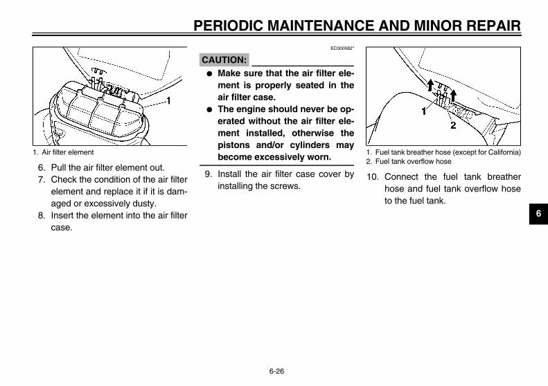
AND MINOR REPAIR
6
67
8
. Connect the fuel tank breatherhose and fuel tank overflow hoseto the fuel tank.
1. Fuel tank breather hose (except for California)Fuel tank overflow hose
U5SL10.book Page 26 Friday, November 1, 2002 4:33 PM
PERIODIC MAINTENANCE
6-26
. Pull the air filter element out.
. Check the condition of the air filterelement and replace it if it is dam-aged or excessively dusty.
. Insert the element into the air filtercase.
EC000082*
CAUTION:_
� Make sure that the air filter ele-ment is properly seated in theair filter case.
� The engine should never be op-erated without the air filter ele-ment installed, otherwise thepistons and/or cylinders maybecome excessively worn.
_
9. Install the air filter case cover byinstalling the screws.
10
Air filter element 1.2.

PE
6
11.EAU01335
intake duct ck that the screen of the intaket is not blocked. Clean the screen ifessary.
1. F2. F
ir intake duct
U5SL10.book Page 27 Friday, November 1, 2002 4:33 PM
RIODIC MAINTENANCE AND MINOR REPAIR
6-27
Place the fuel tank in the originalposition, and then install the bolts.
EWA00071
WARNING_
� Before placing the fuel tank inthe original position, make surethat the fuel hoses are not dam-aged. If any fuel hose is dam-aged, do not start the enginebut have a Yamaha dealer re-place the hose, otherwise fuelmay leak.
� Make sure that the fuel hosesare properly connected androuted, and not pinched.
� Be sure to place the fuel tankbreather hose and the fuel tankoverflow hose in the original po-sition.
_
12. Install the rider seat.
AirCheducnec
uel tank breather hose (except for California)uel tank overflow hose
1. A
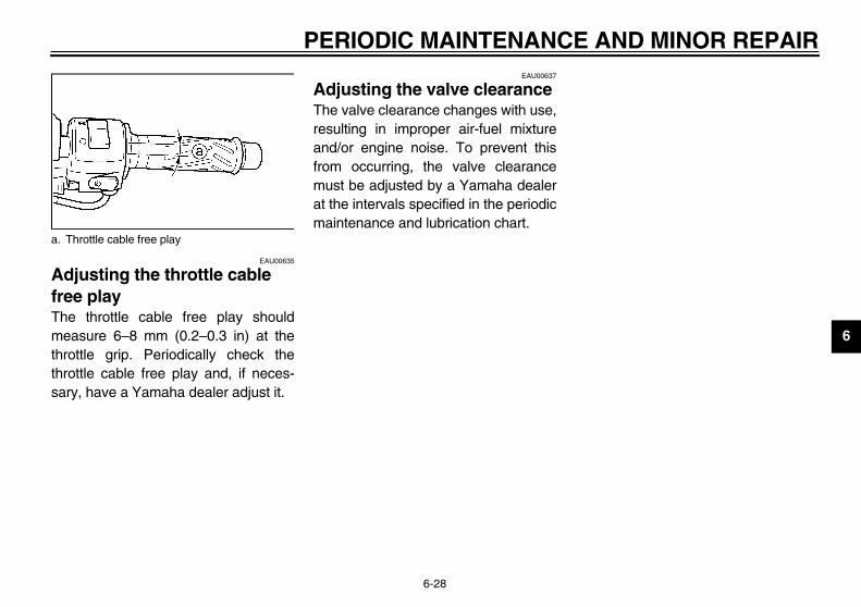
AND MINOR REPAIR
6
AfrThmththsa
a.
U5SL10.book Page 28 Friday, November 1, 2002 4:33 PM
PERIODIC MAINTENANCE
6-28
EAU00635
djusting the throttle cable ee play e throttle cable free play should
easure 6–8 mm (0.2–0.3 in) at therottle grip. Periodically check therottle cable free play and, if neces-ry, have a Yamaha dealer adjust it.
EAU00637
Adjusting the valve clearance The valve clearance changes with use,resulting in improper air-fuel mixtureand/or engine noise. To prevent thisfrom occurring, the valve clearancemust be adjusted by a Yamaha dealerat the intervals specified in the periodicmaintenance and lubrication chart.
Throttle cable free play

PE
6
TirTo ity,cycreg
TirThechebef
_
�
�
_
EW000083
WARNINGper loading of your motorcyclemportant for several characteris- of your motorcycle, such asdling, braking, performance and
ety. Do not carry loosely packeds that can shift. Securely packr heaviest items close to theter of the motorcycle, and dis-ute the weight evenly from sideide. Properly adjust the suspen-
n for your load, and check thedition and pressure of your tires.
VER OVERLOAD YOUR MOTOR-CLE. Make sure that the totalight of the cargo, rider, passen-, and accessories (cowling, sad-bags, etc. if approved for thisdel) does not exceed the maxi-m load of the motorcycle. Opera- of an overloaded motorcycleld cause tire damage, an acci-t, or even injury.
U5SL10.book Page 29 Friday, November 1, 2002 4:33 PM
RIODIC MAINTENANCE AND MINOR REPAIR
6-29
EAU03581
es maximize the performance, durabil- and safe operation of your motor-le, note the following pointsarding the specified tires.
e air pressure tire air pressure should becked and, if necessary, adjustedore each ride.
EW000082
WARNINGThe tire air pressure must bechecked and adjusted on coldtires (i.e., when the temperatureof the tires equals the ambienttemperature). The tire air pressure must beadjusted in accordance with theriding speed and with the totalweight of rider, passenger, car-go, and accessories approvedfor this model.
CE-22E
CE-16E
_
Prois iticshansafitemyoucentribto ssioconNECYwegerdlemomutioncouden_
Tire air pressure(measured on cold tires)
Load* Front Rear
Up to 90 kg (198 lb)250 kPa(2.50 kgf/cm2,36 psi)
250 kPa(2.50 kgf/cm2,36 psi)
90 kg (198 lb)–maximum
250 kPa(2.50 kgf/cm2,36 psi)
290 kPa(2.90 kgf/cm2,42 psi)
High-speed riding250 kPa(2.50 kgf/cm2,36 psi)
250 kPa(2.50 kgf/cm2,36 psi)
Maximum load*YZF-R6: 193 kg (426 lb)YZF-R6C:192 kg (423 lb)
* Total weight of rider, passenger, cargo and accessories

AND MINOR REPAIR
6
TiAlthcrif intahaCE
re informationis motorcycle is equipped with casteels and tubeless tires with valves.
1.2.a.
M(
Tire air valveTire air valve coreTire air valve cap with seal
U5SL10.book Page 30 Friday, November 1, 2002 4:33 PM
PERIODIC MAINTENANCE
6-30
re inspectionways check the tires before operatinge motorcycle. If a tire tread showsosswise lines (minimum tread depth),the tire has a nail or glass fragments it, or if the sidewall is cracked, con-ct a Yamaha dealer immediately andve the tire replaced.
-09E
EW000094
WARNING_
� It is dangerous to ride with aworn-out tire. When a tire treadbegins to show crosswise lines,have a Yamaha dealer replacethe tire immediately.
� The replacement of all wheel-and brake-related parts, includ-ing the tires, should be left to aYamaha dealer, who has thenecessary professional knowl-edge and experience.
_
TiThwh
Tire sidewallTire wear indicatorTire tread depth
inimum tire tread depth front and rear)
1.0 mm (0.04 in)
1.2.3.

PE
6
_
�
�
�
�
_
EAU00684
WARNINGs motorcycle is fitted with super-h-speed tires. Note the followingnts in order to make the most ef-ent use of these tires.
Use only the specified replace-ment tires. Other tires may runthe danger of bursting at superhigh speeds.Brand-new tires can have a rela-tively poor grip on certain roadsurfaces until they have been“broken in”. Therefore, it is ad-visable before doing any high-speed riding to ride conserva-tively for approximately 100 km(60 mi) after installing a newtire.The tires must be warmed upbefore a high-speed run.Always adjust the tire air pres-sure according to the operatingconditions.
U5SL10.book Page 31 Friday, November 1, 2002 4:33 PM
RIODIC MAINTENANCE AND MINOR REPAIR
6-31
EW000080
WARNINGThe front and rear tires shouldbe of the same make and de-sign, otherwise the handlingcharacteristics of the motor-cycle cannot be guaranteed.After extensive tests, only thetires listed below have been ap-proved for this model byYamaha Motor Co., Ltd.Always make sure that the valvecaps are securely installed toprevent air pressure leakage.Use only the tire valves andvalve cores listed below toavoid tire deflation during ahigh-speed ride.
CE-10E
CE-14E
@
Thihigpoifici
�
�
�
�
@
FRONT
Manufacturer Size Model
Michelin 120/60 ZR17 M/C (55W) Pilot SPORT N
Dunlop 120/60 ZR17 M/C (55W) D208F L
REAR
Manufacturer Size Model
Michelin 180/55 ZR17 M/C (73W) Pilot SPORT B
Dunlop 180/55 ZR17 M/C (73W) D208 L
FRONT & REAR
Tire air valve TR412
Valve core #9000A (original)

AND MINOR REPAIR
6
CToitycyre
the use of items which have noten approved by Yamaha.
U5SL10.book Page 32 Friday, November 1, 2002 4:33 PM
PERIODIC MAINTENANCE
6-32
EAU03773
ast wheels maximize the performance, durabil-, and safe operation of your motor-cle, note the following pointsgarding the specified wheels.� The wheel rims should be checked
for cracks, bends or warpage be-fore each ride. If any damage isfound, have a Yamaha dealer re-place the wheel. Do not attempteven the smallest repair to thewheel. A deformed or crackedwheel must be replaced.
� The wheel should be balancedwhenever either the tire or wheelhas been changed or replaced. Anunbalanced wheel can result inpoor performance, adverse han-dling characteristics, and a short-ened tire life.
� Ride at moderate speeds afterchanging a tire since the tire sur-face must first be “broken in” for itto develop its optimal characteris-tics.
EAU00691
Accessories and replacement parts
EW000098
WARNING_
This motorcycle is not designed topull a trailer or to be attached to asidecar. The accessories or replace-ment parts you choose for yourmotorcycle should be designed spe-cifically for this model, and theymust be securely mounted to main-tain the inherent stability of the orig-inal design. Genuine Yamaha Partsand Accessories are designed andtested to be compatible with yourmotorcycle. Please consider Genu-ine Yamaha Parts and Accessoriesbefore making a purchase. Use ofnon-Yamaha-approved accessoriesor replacement parts may causeloss of handling stability and ridingsafety. Since Yamaha cannot con-trol the quality of accessories orparts manufactured by other com-panies, Yamaha cannot be held lia-ble for any consequences caused
bybe_

PE
6
AdplaThesurPeplalowTo turnverclubol
Remove cowling A. (See page 6-9for cowling removal and installa-tion procedures.)Loosen the locknut at the crank-case.To increase the clutch lever freeplay, turn the adjusting nut in di-rection a. To decrease the clutchlever free play, turn the adjustingnut in direction b.Tighten the locknut.Install the cowling.
1. Cc. C
ocknutlutch lever free play adjusting nut rankcase)
U5SL10.book Page 33 Friday, November 1, 2002 4:33 PM
RIODIC MAINTENANCE AND MINOR REPAIR
6-33
EAU01356
justing the clutch lever free y clutch lever free play should mea-
e 10–15 mm (0.4–0.6 in) as shown.riodically check the clutch lever freey and, if necessary, adjust it as fol-s.increase the clutch lever free play, the adjusting bolt at the clutch le-
in direction a. To decrease thetch lever free play, turn the adjustingt in direction b.
NOTE:_
If the specified clutch lever free playcannot be obtained as describedabove, proceed as follows. _
1. Fully turn the adjusting bolt at theclutch lever in direction a to loos-en the clutch cable.
2.
3.
4.
5.6.
lutch lever free play adjusting boltlutch lever free play
1. L2. C
(c

AND MINOR REPAIR
6
ApThpo(0fochneju
EAU00713
djusting the rear brake light itch
e rear brake light switch, which is ac-ated by the brake pedal, is properlyjusted when the brake light comes just before braking takes effect. Ifcessary, adjust the brake light switch follows.rn the adjusting nut while holding the
ar brake light switch in place. Toake the brake light come on earlier,rn the adjusting nut in direction a. Toake the brake light come on later,rn the adjusting nut in direction b.
a. Rear brake light switchRear brake light switch adjusting nut
U5SL10.book Page 34 Friday, November 1, 2002 4:33 PM
PERIODIC MAINTENANCE
6-34
EAU01357
djusting the brake pedal osition e top of the brake pedal should besitioned approximately 7–11 mm.28–0.43 in) below the bottom of theotrest bracket as shown. Periodicallyeck the brake pedal position and, ifcessary, have a Yamaha dealer ad-
st it.
EW000109
WARNING_
A soft or spongy feeling in the brakepedal can indicate the presence ofair in the hydraulic system. If thereis air in the hydraulic system, have aYamaha dealer bleed the system be-fore operating the motorcycle. Air inthe hydraulic system will diminishthe braking performance, whichmay result in loss of control and anaccident. _
AswThtivadonneasTuremtumtu
Distance between brake pedal and footrest bracket
1.2.
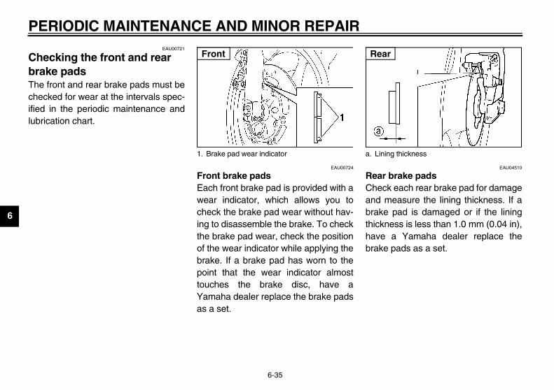
PE
6
ChbrThecheifielub
EAU04510
r brake padsck each rear brake pad for damage measure the lining thickness. If ake pad is damaged or if the liningkness is less than 1.0 mm (0.04 in),e a Yamaha dealer replace theke pads as a set.
ining thickness
ar
U5SL10.book Page 35 Friday, November 1, 2002 4:33 PM
RIODIC MAINTENANCE AND MINOR REPAIR
6-35
EAU00721
ecking the front and rear ake pads front and rear brake pads must becked for wear at the intervals spec-
d in the periodic maintenance andrication chart.
EAU00724
Front brake padsEach front brake pad is provided with awear indicator, which allows you tocheck the brake pad wear without hav-ing to disassemble the brake. To checkthe brake pad wear, check the positionof the wear indicator while applying thebrake. If a brake pad has worn to thepoint that the wear indicator almosttouches the brake disc, have aYamaha dealer replace the brake padsas a set.
ReaCheandbrathichavbra
1. Brake pad wear indicator
Front
a. L
Re
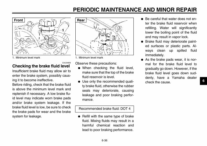
AND MINOR REPAIR
6
CIneninBeisreidanbrthsy
� Be careful that water does not en-ter the brake fluid reservoir whenrefilling. Water will significantlylower the boiling point of the fluidand may result in vapor lock.
� Brake fluid may deteriorate paint-ed surfaces or plastic parts. Al-ways clean up spilled fluidimmediately.
� As the brake pads wear, it is nor-mal for the brake fluid level togradually go down. However, if thebrake fluid level goes down sud-denly, have a Yamaha dealercheck the cause.
1.
F
U5SL10.book Page 36 Friday, November 1, 2002 4:33 PM
PERIODIC MAINTENANCE
6-36
EAU04856
hecking the brake fluid level sufficient brake fluid may allow air toter the brake system, possibly caus-
g it to become ineffective.fore riding, check that the brake fluid
above the minimum level mark andplenish if necessary. A low brake flu- level may indicate worn brake padsd/or brake system leakage. If theake fluid level is low, be sure to checke brake pads for wear and the brakestem for leakage.
Observe these precautions:� When checking the fluid level,
make sure that the top of the brakefluid reservoir is level.
� Use only the recommended quali-ty brake fluid, otherwise the rubberseals may deteriorate, causingleakage and poor braking perfor-mance.
� Refill with the same type of brakefluid. Mixing fluids may result in aharmful chemical reaction andlead to poor braking performance.
Minimum level mark
ront
1. Minimum level mark
Recommended brake fluid: DOT 4
Rear

PE
6
ChHabrathenanhavderhosbelor l
�
�
Move the rear wheel by pushingthe motorcycle to locate the tight-est portion of the drive chain, andthen measure the drive chainslack as shown.
If the drive chain slack is incorrect,adjust it as follows.
rive chain slack
rive chain slack:35–45 mm (1.4–1.8 in)
U5SL10.book Page 37 Friday, November 1, 2002 4:33 PM
RIODIC MAINTENANCE AND MINOR REPAIR
6-37
EAU03976
anging the brake fluid ve a Yamaha dealer change theke fluid at the intervals specified in NOTE after the periodic mainte-ce and lubrication chart. In addition,e the oil seals of the master cylin-s and calipers as well as the brakees replaced at the intervals listed
ow or whenever they are damagedeaking.
Oil seals: Replace every twoyears.Brake hoses: Replace every fouryears.
EAU00744
Drive chain slack The drive chain slack should bechecked before each ride and adjustedif necessary.
To check the drive chain slack 1. Place the motorcycle on a level
surface and hold it in an uprightposition.
NOTE:_
When checking and adjusting the drivechain slack, the motorcycle should bepositioned straight up and there shouldbe no weight on it. _
2. Shift the transmission into the neu-tral position.
3.
4.
a. D
D

AND MINOR REPAIR
6To
1
2
1.2.3.4.
U5SL10.book Page 38 Friday, November 1, 2002 4:33 PM
PERIODIC MAINTENANCE
6-38
EAU03608
adjust the drive chain slack . Loosen the axle nut and the lock-
nut on each side of the swingarm.. To tighten the drive chain, turn the
adjusting bolt on each side of theswingarm in direction a. To loos-en the drive chain, turn the adjust-ing bolt on each side of theswingarm in direction b, and thenpush the rear wheel forward.
NOTE:_
Using the alignment marks on eachside of the swingarm, make sure thatboth chain pullers are in the same posi-tion for proper wheel alignment. _
EC000096
CAUTION:_
Improper drive chain slack will over-load the engine as well as other vitalparts of the motorcycle and can leadto chain slippage or breakage. Toprevent this from occurring, keepthe drive chain slack within thespecified limits. _
3. Tighten the locknuts, and thentighten the axle nut to the specifiedtorque.
Axle nutDrive chain slack adjusting boltLocknutAlignment marks
Tightening torque:Axle nut:
110 Nm (11.0 m·kgf, 80 ft·lbf)
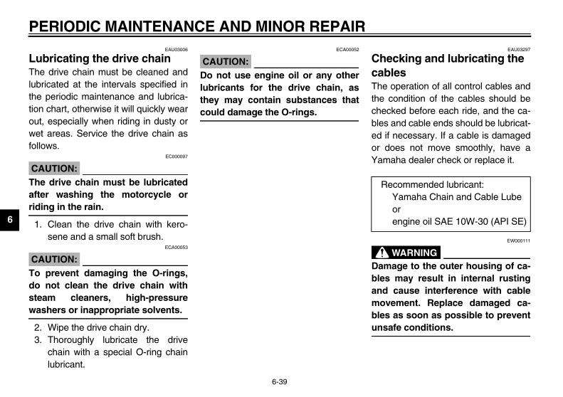
PE
6
LuThelubthetionoutwefoll
CA@
Thaftrid@
1.
CA@
Todostewa@
2.3.
EAU03297
ecking and lubricating the bles operation of all control cables and
condition of the cables should becked before each ride, and the ca-
s and cable ends should be lubricat-if necessary. If a cable is damageddoes not move smoothly, have a
aha dealer check or replace it.
EW000111
WARNINGage to the outer housing of ca-
s may result in internal rusting cause interference with cablevement. Replace damaged ca-s as soon as possible to preventafe conditions.
ecommended lubricant:Yamaha Chain and Cable Lube orengine oil SAE 10W-30 (API SE)
U5SL10.book Page 39 Friday, November 1, 2002 4:33 PM
RIODIC MAINTENANCE AND MINOR REPAIR
6-39
EAU03006
bricating the drive chain drive chain must be cleaned and
ricated at the intervals specified in periodic maintenance and lubrica- chart, otherwise it will quickly wear, especially when riding in dusty ort areas. Service the drive chain asows.
EC000097
UTION:e drive chain must be lubricateder washing the motorcycle oring in the rain.
Clean the drive chain with kero-sene and a small soft brush.
ECA00053
UTION: prevent damaging the O-rings, not clean the drive chain witham cleaners, high-pressureshers or inappropriate solvents.
Wipe the drive chain dry.Thoroughly lubricate the drivechain with a special O-ring chainlubricant.
ECA00052
CAUTION:@
Do not use engine oil or any otherlubricants for the drive chain, asthey may contain substances thatcould damage the O-rings. @
ChcaThethechebleed or Yam
_
Dambleandmobleuns_
R
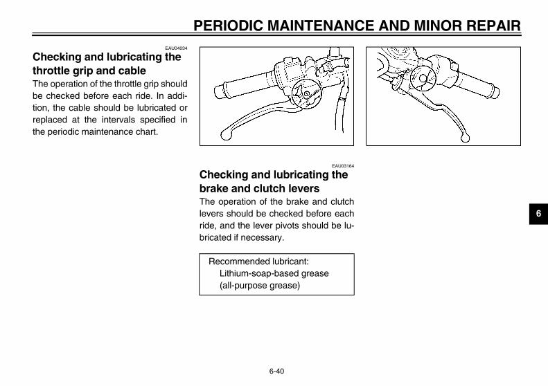
AND MINOR REPAIR
6
CthThbetioreth
U5SL10.book Page 40 Friday, November 1, 2002 4:33 PM
PERIODIC MAINTENANCE
6-40
EAU04034
hecking and lubricating the rottle grip and cable e operation of the throttle grip should checked before each ride. In addi-n, the cable should be lubricated orplaced at the intervals specified ine periodic maintenance chart.
EAU03164
Checking and lubricating the brake and clutch levers The operation of the brake and clutchlevers should be checked before eachride, and the lever pivots should be lu-bricated if necessary.
Recommended lubricant:Lithium-soap-based grease (all-purpose grease)

PE
6
ChbrThepedridebric
EAU03165
ecking and lubricating the estand operation of the sidestand shouldchecked before each ride, and thestand pivot and metal-to-metaltact surfaces should be lubricated ifessary.
EW000113
WARNINGhe sidestand does not move up down smoothly, have a Yamahaler check or repair it.
R
ecommended lubricant:Lithium-soap-based grease (all-purpose grease)
U5SL10.book Page 41 Friday, November 1, 2002 4:33 PM
RIODIC MAINTENANCE AND MINOR REPAIR
6-41
EAU03370
ecking and lubricating the ake and shift pedals operation of the brake and shiftals should be checked before each, and the pedal pivots should be lu-ated if necessary.
ChsidThebe sideconnec
@
If tanddea@
ecommended lubricant:Lithium-soap-based grease (all-purpose grease)
R

AND MINOR REPAIR
6
LpThedod
check the operation. Place the motorcycle on a level
surface and hold it in an uprightposition.
. While applying the front brake,push down hard on the handle-bars several times to check if thefront fork compresses and re-bounds smoothly.
EC000098
AUTION:any damage is found or the frontrk does not operate smoothly,ve a Yamaha dealer check or re-ir it.
U5SL10.book Page 42 Friday, November 1, 2002 4:33 PM
PERIODIC MAINTENANCE
6-42
EAUM1380
ubricating the swingarm ivot e swingarm pivots must be lubricat- at the intervals specified in the peri-ic maintenance and lubrication chart.
EAU02939
Checking the front fork The condition and operation of the frontfork must be checked as follows at theintervals specified in the periodic main-tenance and lubrication chart.
To check the conditionEW000115
WARNING@
Securely support the motorcycle sothat there is no danger of it fallingover. @
Check the inner tubes for scratches,damage and excessive oil leakage.
To1
2
C@
If fohapa@
Recommended lubricant:Lithium-soap-based grease

PE
6
ChWocauof tlowriodcha
1.
@
Sethaove@
EAU01144
ecking the wheel bearings front and rear wheel bearings must
checked at the intervals specified in periodic maintenance and lubrica- chart. If there is play in the wheel or if the wheel does not turn
oothly, have a Yamaha dealerck the wheel bearings.
U5SL10.book Page 43 Friday, November 1, 2002 4:33 PM
RIODIC MAINTENANCE AND MINOR REPAIR
6-43
EAU00794
ecking the steering rn or loose steering bearings mayse danger. Therefore, the operationhe steering must be checked as fol-s at the intervals specified in the pe-ic maintenance and lubricationrt.Place a stand under the engine toraise the front wheel off theground.
EW000115
WARNINGcurely support the motorcycle sot there is no danger of it fallingr.
2. Hold the lower ends of the frontfork legs and try to move them for-ward and backward. If any freeplay can be felt, have a Yamahadealer check or repair thesteering.
ChThebe thetionhubsmche

AND MINOR REPAIR
6
BThsenonoad
ToHtehabaif tio
� KEEP THIS AND ALL BATTER-IES OUT OF THE REACH OFCHILDREN.
store the battery. If the motorcycle will not be used
for more than one month, removethe battery, fully charge it, andthen place it in a cool, dry place.
. If the battery will be stored formore than two months, check it atleast once a month and fullycharge it if necessary.
. Fully charge the battery before in-stallation.
. After installation, make sure thatthe battery leads are properly con-nected to the battery terminals.
U5SL10.book Page 44 Friday, November 1, 2002 4:33 PM
PERIODIC MAINTENANCE
6-44
EAU01291
attery is motorcycle is equipped with aaled-type (MF) battery, which doest require any maintenance. There is need to check the electrolyte or tod distilled water.
charge the batteryave a Yamaha dealer charge the bat-ry as soon as possible if it seems tove discharged. Keep in mind that thettery tends to discharge more quicklythe motorcycle is equipped with op-nal electrical accessories.
EW000116
WARNING@
� Electrolyte is poisonous anddangerous since it contains sul-furic acid, which causes severeburns. Avoid any contact withskin, eyes or clothing and al-ways shield your eyes whenworking near batteries. In caseof contact, administer the fol-lowing FIRST AID.• EXTERNAL: Flush with plenty
of water.• INTERNAL: Drink large quan-
tities of water or milk and im-mediately call a physician.
• EYES: Flush with water for15 minutes and seek promptmedical attention.
� Batteries produce explosive hy-drogen gas. Therefore, keepsparks, flames, cigarettes, etc.,away from the battery and pro-vide sufficient ventilation whencharging it in an enclosedspace.
@
To1
2
3
4

PE
6
CA@
�
�
@Remove the blown fuse, and theninstall a new fuse of the specifiedamperage.
eadlight fuseadiator fan fusenition fuseignaling system fusedometer and clock fuse (backup fuse)lectronic fuel injection fusepare fuse (× 3)
U5SL10.book Page 45 Friday, November 1, 2002 4:33 PM
RIODIC MAINTENANCE AND MINOR REPAIR
6-45
EC000102
UTION:Always keep the batterycharged. Storing a dischargedbattery can cause permanentbattery damage.To charge a sealed-type (MF)battery, a special (constant-voltage) battery charger is re-quired. Using a conventionalbattery charger will damage thebattery. If you do not have ac-cess to a sealed-type (MF) bat-tery charger, have a Yamahadealer charge your battery.
EAU05007
Replacing the fuses The main fuse is located under the rid-er seat. (See page 3-16 for rider seatremoval and installation procedures.)The fuse box, which contains the fusesfor the individual circuits, is located un-der panel B. (See page 6-11 for panelremoval and installation procedures.)If a fuse is blown, replace it as follows.
1. Turn the key to “OFF” and turn offthe electrical circuit in question.
2.
1. Spare main fuse 2. Main fuse
1. H2. R3. Ig4. S5. O6. E7. S

AND MINOR REPAIR
6
C_
Dagavthfir_
3
4
. Disconnect the headlight coupler.
Headlight coupler
U5SL10.book Page 46 Friday, November 1, 2002 4:33 PM
PERIODIC MAINTENANCE
6-46
EC000103
AUTION:o not use a fuse of a higher amper-e rating than recommended tooid causing extensive damage toe electrical system and possibly ae.
. Turn the key to “ON” and turn onthe electrical circuit in question tocheck if the device operates.
. If the fuse immediately blowsagain, have a Yamaha dealercheck the electrical system.
EAU04954
Replacing a headlight bulb This motorcycle is equipped withquartz bulb headlights. If a headlightbulb burns out, replace it as follows.
1. Remove panel B (if replacing theleft headlight bulb) or panel A (ifreplacing the right headlight bulb).(See page 6-11 for panel removaland installation procedures.)
2. Remove the headlight bulb coverby turning it counterclockwise.
3
Specified fuses:Main fuse: 40 AHeadlight fuse: 20 ASignaling system fuse: 15 ARadiator fan fuse: 15 AIgnition fuse: 15 AElectronic fuel injection fuse: 15 AOdometer and clock fuse (backup fuse): 10 A
1. Headlight bulb cover 1.

PE
6
4.
EC000104
UTION:e care not to damage the follow- parts:Headlight bulbDo not touch the glass part ofthe headlight bulb to keep it freefrom oil, otherwise the transpar-ency of the glass, the luminosi-ty of the bulb, and the bulb lifewill be adversely affected. Thor-oughly clean off any dirt and fin-gerprints on the headlight bulbusing a cloth moistened with al-cohol or thinner.Headlight lens• Do not affix any type of tinted
film or stickers to the head-light lens.
• Do not use a headlight bulb ofa wattage higher than speci-fied.
1. H
U5SL10.book Page 47 Friday, November 1, 2002 4:33 PM
RIODIC MAINTENANCE AND MINOR REPAIR
6-47
Unhook the headlight bulb holder,and then remove the defectivebulb.
EW000119
WARNING_
Headlight bulbs get very hot. There-fore, keep flammable products awayfrom a lit headlight bulb, and do nottouch the bulb until it has cooleddown. _
5. Place a new headlight bulb intoposition, and then secure it withthe bulb holder.
CA_
Taking
�
�
_
eadlight bulb holder 1. Do not touch the glass part of the bulb.

AND MINOR REPAIR
6
67
89
EAU03497
eplacing a turn signal light lb
. Remove the turn signal light lensby removing the screw.
. Remove the defective bulb bypushing it in and turning itcounterclockwise.
. Insert a new bulb into the socket,push it in, and then turn it clock-wise until it stops.
. Install the lens by installing thescrew.
ECA00065
AUTION: not overtighten the screw, other-
ise the lens may break.
Screw
U5SL10.book Page 48 Friday, November 1, 2002 4:33 PM
PERIODIC MAINTENANCE
6-48
. Connect the headlight coupler.
. Install the headlight bulb cover byturning it clockwise.
. Install the panel.
. Have a Yamaha dealer adjust theheadlight beam if necessary.
EAU03730
Tail/brake light This motorcycle is equipped with anLED type of tail/brake light. If the tail/brake light does not come on,have a Yamaha dealer check it.
Rbu
1
2
3
4
C@
Dow@
1.

PE
6
Relig
1.
EAU01579
pporting the motorcycle ce this model is not equipped with aterstand, follow these precautionsn removing the front and rearel or performing other mainte-ce requiring the motorcycle to
nd upright. Check that the motor-le is in a stable and level positionore starting any maintenance. Ang wooden box can be placed un- the engine for added stability.
service the front wheelStabilize the rear of the motorcycleby using a motorcycle stand or, ifan additional motorcycle stand isnot available, by placing a jack un-der the frame in front of the rearwheel.Raise the front wheel off theground by using a motorcyclestand.
1. S
U5SL10.book Page 49 Friday, November 1, 2002 4:33 PM
RIODIC MAINTENANCE AND MINOR REPAIR
6-49
EAU04574
placing the license plate ht bulb
Remove the license plate light unitby removing the screws.
2. Remove the socket (together withthe bulb) by pulling it out.
3. Remove the defective bulb by pull-ing it out.
4. Insert a new bulb into the socket.5. Install the socket (together with
the bulb) by pushing it in.6. Install the license plate light unit by
installing the screws.
SuSincenwhewhenanstacycbefstroder
To 1.
2.
crew (× 2) 1. License plate light bulb2. License plate light unit

AND MINOR REPAIR
6
ToRuscya fraea
. Lift the front wheel off the groundaccording to the procedure onpage 6-49.
. Remove the brake hose holder oneach side by removing the bolt.
. Remove the brake caliper and re-flector on each side by removingthe bolts.
Brake hose holderReflectorBrake caliperAxle boltBolt (× 3)
U5SL10.book Page 50 Friday, November 1, 2002 4:33 PM
PERIODIC MAINTENANCE
6-50
service the rear wheelaise the rear wheel off the ground bying a motorcycle stand or, if a motor-cle stand is not available, by placingjack either under each side of theme in front of the rear wheel or underch side of the swingarm.
EAU05008
Front wheel
To remove the front wheel EW000122
WARNING_
� It is advisable to have a Yamahadealer service the wheel.
� Securely support the motor-cycle so that there is no dangerof it falling over.
_
1. Loosen the axle bolt, the wheelaxle pinch bolts, and then thebrake caliper bolts.
2
3
4
1. Front wheel axle pinch bolt (× 4) 1.2.3.4.5.

PE
6
5.
CA_
Dobraothfor_
Secure the wheel axle by installingthe axle bolt, and then tighteningthe wheel axle to the specifiedtorque.
TE:ile tightening the wheel axle, hold axle bolt to keep it from turning.
1. W ightening torque:Wheel axle:
91 Nm (9.1 m·kgf, 66 ft·lbf)
U5SL10.book Page 51 Friday, November 1, 2002 4:33 PM
RIODIC MAINTENANCE AND MINOR REPAIR
6-51
Remove the axle bolt, pull thewheel axle out, and then removethe wheel.
ECA00046
UTION: not apply the brake after theke calipers have been removed,erwise the brake pads will beced shut.
EAU05023
To install the front wheel 1. Lift the wheel up between the fork
legs.2. Insert the wheel axle.3. Lower the front wheel so that it is
on the ground.4. Install the brake calipers and re-
flectors by installing the bolts, andthen tightening them to the speci-fied torque.
NOTE:_
Make sure that there is enough spacebetween the brake pads before install-ing the brake calipers onto the brakediscs. _
5. Install the brake hose holders byinstalling the bolts.
6.
NO_
Whthe_
heel axle
Tightening torque:Brake caliper bolt:
40 Nm (4.0 m·kgf, 29 ft·lbf)
T

AND MINOR REPAIR
6
7
8
9
1.2.3.4.
U5SL10.book Page 52 Friday, November 1, 2002 4:33 PM
PERIODIC MAINTENANCE
6-52
. Tighten wheel axle pinch bolt B,and then tighten pinch bolt A to thespecified torque.
. Retighten pinch bolt B to the spec-ified torque.
. Tap the outer side of the left forkleg with a rubber mallet to align itwith the end of the wheel axle.
10. Tighten wheel axle pinch bolt D,and then tighten pinch bolt C to thespecified torque.
11. Retighten pinch bolt D to the spec-ified torque.
12. While applying the front brake,push down hard on the handlebarseveral times to check for properfork operation.
Front wheel axle pinch bolt AFront wheel axle pinch bolt BFront wheel axle pinch bolt CFront wheel axle pinch bolt D
Tightening torque:Wheel axle pinch bolt:
18 Nm (1.8 m·kgf, 13 ft·lbf)
Tightening torque:Wheel axle pinch bolt:
18 Nm (1.8 m·kgf, 13 ft·lbf)

PE
6 Re
To
_
�
�
_
1.
Push the wheel forward, and thenremove the drive chain from therear sprocket.
TE: drive chain does not need to bessembled in order to remove andall the rear wheel.
1. A2. D3. L4. B5. B
U5SL10.book Page 53 Friday, November 1, 2002 4:33 PM
RIODIC MAINTENANCE AND MINOR REPAIR
6-53
EAU04947
ar wheel
remove the rear wheel EW000122
WARNINGIt is advisable to have a Yamahadealer service the wheel.Securely support the motor-cycle so that there is no dangerof it falling over.
Loosen the axle nut.
2. Lift the rear wheel off the groundaccording to the procedure onpage 6-49.
3. Remove the axle nut.4. Loosen the locknut on each side of
the swingarm.5. Turn the drive chain slack adjust-
ing bolts fully in direction a.
6.
NO_
Thedisainst_
xle nutrive chain slack adjusting boltocknutrake caliper rake caliper bracket

AND MINOR REPAIR
6
7
C_
Dwwbr_
. Install the drive chain onto the rearsprocket, and then adjust the drivechain slack. (See page 6-38 fordrive chain slack adjustment pro-cedures.)
. Install the axle nut, and then lowerthe rear wheel so that it is on theground.
. Tighten the axle nut to the speci-fied torque.
1.
Tightening torque:Axle nut:
110 Nm (11.0 m·kgf, 79.6 ft·lbf)
U5SL10.book Page 54 Friday, November 1, 2002 4:33 PM
PERIODIC MAINTENANCE
6-54
. While supporting the brake caliperbracket, pull the wheel axle out,and then remove the wheel.
ECA00048
AUTION:o not apply the brake after theheel has been removed togetherith the brake disc, otherwise theake pads will be forced shut.
EAU04948
To install the rear wheel 1. Install the wheel and the brake cal-
iper bracket by inserting the wheelaxle from the left-hand side.
NOTE:_
� Be sure to insert the retainer onthe brake caliper bracket into theslot in the swingarm.
� Make sure that there is enoughspace between the brake pads be-fore installing the wheel.
_
2
3
4Wheel axle 1. Retainer
2. Slot

PE
6
TrAltha thfromingcomexalosTherepfor selreqdeatheknoproUsmelikeinfecan
U5SL10.book Page 55 Friday, November 1, 2002 4:33 PM
RIODIC MAINTENANCE AND MINOR REPAIR
6-55
EAU03087
oubleshooting ough Yamaha motorcycles receiveorough inspection before shipment the factory, trouble may occur dur-
operation. Any problem in the fuel,pression, or ignition systems, formple, can cause poor starting and
s of power. following troubleshooting charts
resent quick and easy procedureschecking these vital systems your-f. However, should your motorcycleuire any repair, take it to a Yamahaler, whose skilled technicians have
necessary tools, experience, andw-how to service the motorcycleperly.e only genuine Yamaha replace-nt parts. Imitation parts may look Yamaha parts, but they are oftenrior, have a shorter service life and lead to expensive repair bills.

AND MINOR REPAIR
6
EAU02990
TroubleshootingStarting problems
EW000125
WARNING@
Keep away open fla ystem. @
s not start. pression.
The engine does not start.Have a Yamaha dealercheck the vehicle.
e engine does not start.eck the battery.
en the throttle halfway and operate electric starter.
U5SL10.book Page 56 Friday, November 1, 2002 4:33 PM
Check the fuel levthe fuel tank.
1. Fuel
Operate the electr
2. Compres
Remove the sparkand check the ele
3. Ignition
Operate the electr
4. Battery
PERIODIC MAINTENANCE
6-56
charts or poor engine performance
mes and do not smoke while checking or working on the fuel s
el inThere is enough fuel.
There is no fuel.
Check the compression.
Supply fuel. The engine doeCheck the com
ic starter.
sionThere is compression.
There is no compression.
Check the ignition.
Have a Yamaha dealercheck the vehicle.
plugsctrodes.
Wipe off with a dry cloth and correct thespark plug gaps, or replace the spark plugs.
Have a Yamaha dealer check the vehicle. ThCh
ic starter.
The engine turns over quickly.
The engine turns over slowly.
The battery is good.
Check the battery lead connections,and charge the battery if necessary.
Dry
WetOpthe
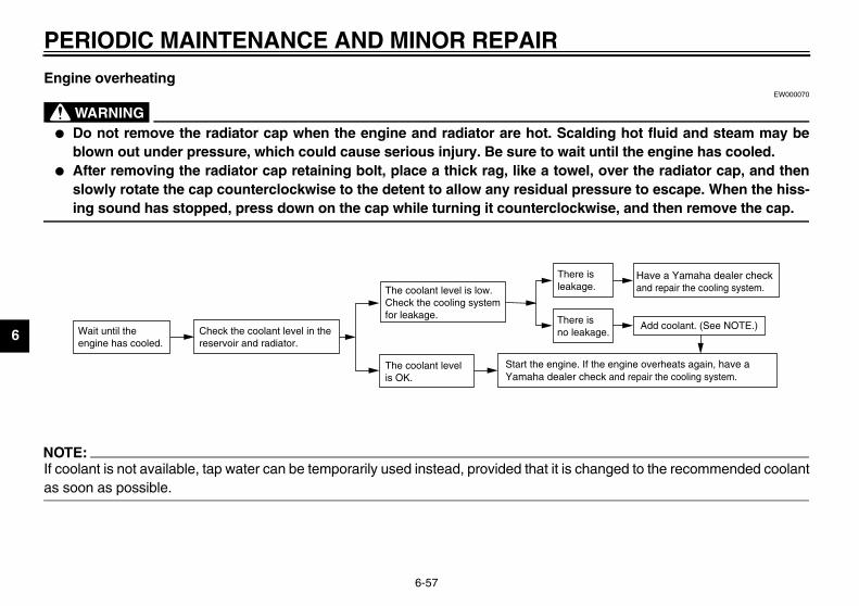
PE
6
EnEW000070
@
� ding hot fluid and steam may be until the engine has cooled.
� l, over the radiator cap, and thenessure to escape. When the hiss-wise, and then remove the cap.
@a
NO@
If c anged to the recommended coolantas @
Have a Yamaha dealer checkand repair the cooling system.
Add coolant. (See NOTE.)
f the engine overheats again, have a eck and repair the cooling system.
ise.
is age.
U5SL10.book Page 57 Friday, November 1, 2002 4:33 PM
RIODIC MAINTENANCE AND MINOR REPAIR
6-57
gine overheating
WARNINGDo not remove the radiator cap when the engine and radiator are hot. Scalblown out under pressure, which could cause serious injury. Be sure to waitAfter removing the radiator cap retaining bolt, place a thick rag, like a toweslowly rotate the cap counterclockwise to the detent to allow any residual pring sound has stopped, press down on the cap while turning it counterclock
TE:oolant is not available, tap water can be temporarily used instead, provided that it is chsoon as possible.
Wait until the engine has cooled.
Check the coolant level in the reservoir and radiator.
The coolant level is OK.
The coolant level is low.Check the cooling systemfor leakage.
Start the engine. IYamaha dealer ch
There leakag
There no leak

MOTORCYCLE CARE AND STORAGE
7
Care .................................................................................................. 7-1Storage .............................................................................................. 7-4
U5SL10.book Page 1 Friday, November 1, 2002 4:33 PM

7
EAU04958
aningECA00010
UTION:
U5SL10.book Page 1 Friday, November 1, 2002 4:33 PM
7-MO
CaWhreve
Avoid using strong acidic wheelcleaners, especially on spokedwheels. If such products areused on hard-to-remove dirt, donot leave the cleaner on the af-fected area any longer than in-structed. Also, thoroughly rinsethe area off with water, immedi-ately dry it, and then apply acorrosion protection spray.Improper cleaning can damagewindshields, cowlings, panelsand other plastic parts. Useonly a soft, clean cloth orsponge with mild detergent andwater to clean plastic.
noloble.eveusenotifrommodoethe moand
7-1
TORCYCLE CARE AND STORAGE
re ile the open design of a motorcycleals the attractiveness of the tech-gy, it also makes it more vulnera- Rust and corrosion can developn if high-quality components ared. A rusty exhaust pipe may go un-ced on a car, however, it detracts the overall appearance of a
torcycle. Frequent and proper cares not only comply with the terms ofwarranty, but it will also keep your
torcycle looking good, extend its life optimize its performance.
Before cleaning1. Cover the muffler outlet with a
plastic bag after the engine hascooled down.
2. Make sure that all caps and coversas well as all electrical couplersand connectors, including thespark plug caps, are tightly in-stalled.
3. Remove extremely stubborn dirt,like oil burnt onto the crankcase,with a degreasing agent and abrush, but never apply such prod-ucts onto seals, gaskets, sprock-ets, the drive chain and wheelaxles. Always rinse the dirt anddegreaser off with water.
Cle
CA_
�
�
ARE AND STORAGE
7
ter riding in the rain, near the sea or salt-sprayed roadsnce sea salt or salt sprayed on roadsring winter are extremely corrosive inmbination with water, carry out thellowing steps after each ride in thein, near the sea or on salt-sprayedads.
TE:lt sprayed on roads in the winter may
main well into spring.
. Clean the motorcycle with coldwater and a mild detergent, afterthe engine has cooled down.
ECA00012
AUTION: not use warm water since it in-
eases the corrosive action of thelt.
. After drying the motorcycle, applya corrosion protection spray on allmetal, including chrome- and nick-el-plated, surfaces to prevent cor-rosion.
U5SL10.book Page 2 Friday, November 1, 2002 4:33 PM
MOTORCYCLE C
7-2
� Do not use any harsh chemicalproducts on plastic parts. Besure to avoid using cloths orsponges which have been incontact with strong or abrasivecleaning products, solvent orthinner, fuel (gasoline), rust re-movers or inhibitors, brake flu-id, antifreeze or electrolyte.
� Do not use high-pressure wash-ers or steam-jet cleaners sincethey cause water seepage anddeterioration in the following ar-eas: seals (of wheel and swing-arm bearings, fork and brakes),electric components (couplers,connectors, instruments,switches and lights), breatherhoses and vents.
� For motorcycles equipped witha windshield: Do not use strongcleaners or hard sponges asthey will cause dulling orscratching. Some cleaningcompounds for plastic mayleave scratches on the wind-
shield. Test the product on asmall hidden part of the wind-shield to make sure that it doesnot leave any marks. If the wind-shield is scratched, use a quali-ty plastic polishing compoundafter washing.
_
After normal useRemove dirt with warm water, a milddetergent, and a soft, clean sponge,and then rinse thoroughly with cleanwater. Use a toothbrush or bottlebrushfor hard-to-reach areas. Stubborn dirtand insects will come off more easily ifthe area is covered with a wet cloth fora few minutes before cleaning. Use thespecial sponge, which is included in theplastic bag containing the owner’smanual, to clean the muffler and to re-move any discoloration from it.
AfonSiducoforaro
NO_
Sare_
1
C_
Docrsa_
2
M
7
Aft1.
2.
3.
4.
5.
6.
7.8.
ECA00013
UTION:Apply spray oil and wax spar-ingly and make sure to wipe offany excess.Never apply oil or wax to anyrubber and plastic parts, buttreat them with a suitable careproduct.Avoid using abrasive polishingcompounds as they will wearaway the paint.
TE:sult a Yamaha dealer for advice ont products to use.
U5SL10.book Page 3 Friday, November 1, 2002 4:33 PM
OTORCYCLE CARE AND STORAGE
7-3
er cleaningDry the motorcycle with a chamoisor an absorbing cloth.Immediately dry the drive chainand lubricate it to prevent it fromrusting.Use a chrome polish to shinechrome, aluminum and stainless-steel parts, including the exhaustsystem. (Even the thermally in-duced discoloring of stainless-steel exhaust systems can be re-moved through polishing.)To prevent corrosion, it is recom-mended to apply a corrosion pro-tection spray on all metal,including chrome- and nickel-plat-ed, surfaces.Use spray oil as a universal clean-er to remove any remaining dirt.Touch up minor paint damagecaused by stones, etc.Wax all painted surfaces.Let the motorcycle dry completelybefore storing or covering it.
EWA00001
WARNING_
� Make sure that there is no oil orwax on the brakes or tires. Ifnecessary, clean the brakediscs and brake linings with aregular brake disc cleaner or ac-etone, and wash the tires withwarm water and a mild deter-gent.
� Before operating the motor-cycle, test its braking perfor-mance and cornering behavior.
_
CA_
�
�
�
_
NO_
Conwha_

ARE AND STORAGE
7
S
ShAldrag
C_
_
e. Remove the spark plug capsfrom the spark plugs, and theninstall the spark plugs and thespark plug caps.
EWA00003
WARNING prevent damage or injury fromarking, make sure to ground theark plug electrodes while turninge engine over.
. Lubricate all control cables andthe pivoting points of all levers andpedals as well as of the sidestand/centerstand.
. Check and, if necessary, correctthe tire air pressure, and then liftthe motorcycle so that both of itswheels are off the ground. Alterna-tively, turn the wheels a little everymonth in order to prevent the tiresfrom becoming degraded in onespot.
U5SL10.book Page 4 Friday, November 1, 2002 4:33 PM
MOTORCYCLE C
7-4
torage
ort-termways store your motorcycle in a cool,y place and, if necessary, protect itainst dust with a porous cover.
ECA00014
AUTION:� Storing the motorcycle in a
poorly ventilated room or cover-ing it with a tarp, while it is stillwet, will allow water and humid-ity to seep in and cause rust.
� To prevent corrosion, avoiddamp cellars, stables (becauseof the presence of ammonia)and areas where strong chemi-cals are stored.
Long-termBefore storing your motorcycle forseveral months:
1. Follow all the instructions in the“Care” section of this chapter.
2. Fill up the fuel tank and add fuelstabilizer (if available) to preventthe fuel tank from rusting and thefuel from deteriorating.
3. Perform the following steps to pro-tect the cylinders, piston rings, etc.from corrosion.a. Remove the spark plug caps
and spark plugs.b. Pour a teaspoonful of engine
oil into each spark plug bore.c. Install the spark plug caps onto
the spark plugs, and then placethe spark plugs on the cylinderhead so that the electrodes aregrounded. (This will limit spark-ing during the next step.)
d. Turn the engine over severaltimes with the starter. (This willcoat the cylinder walls with oil.)
_
Tospspth_
4
5

M
7
6.
7.
NO_
Masto_
U5SL10.book Page 5 Friday, November 1, 2002 4:33 PM
OTORCYCLE CARE AND STORAGE
7-5
Cover the muffler outlet with aplastic bag to prevent moisturefrom entering it.Remove the battery and fullycharge it. Store it in a cool, dryplace and charge it once a month.Do not store the battery in an ex-cessively cold or warm place [lessthan 0 °C (30 °F) or more than30 °C (90 °F)]. For more informa-tion on storing the battery, seepage 6-44.
TE:ke any necessary repairs beforering the motorcycle.

SPECIFICATIONS
8
Specifications .................................................................................... 8-1
U5SL10.book Page 1 Friday, November 1, 2002 4:33 PM

8
EAU01038
U5SL10.book Page 1 Friday, November 1, 2002 4:33 PM
8-SP
SpCS-01
M
oil API Service SE, SF, SG or higher
ridge 2.4 L (2.11 Imp qt, 2.54 US qt)
e 2.6 L (2.29 Imp qt, 2.75 US qt)
gine) 3.4 L (2.99 Imp qt, 3.59 US qt)
0 10 30 50 70 90 110 130 ˚F
YAMALUBE 4 (20W-40)or SAE 20W-40
-20 -10 0 10 20 30 40 50 ˚C
YAMALUBE 4 (10W-30)or SAE 10W-30
clutch slippage (since the engine oil alsoh), do not mix any chemical additives. Do diesel specification of “CD” or oils of a specified. In addition, do not use oils la-NSERVING II” or higher.
D
Bf
E
8-1
ECIFICATIONS
ecifications E
odel YZF-R6(C)
imensions
Overall length 2,025 mm (79.7 in)
Overall width 690 mm (27.2 in)
Overall height 1,090 mm (42.9 in)
Seat height 820 mm (32.3 in)
Wheelbase 1,380 mm (54.3 in)
Ground clearance 135 mm (5.3 in)
Minimum turning radius 3,400 mm (133.9 in)
asic weight (with oil and full uel tank)
YZF-R6 182 kg (401 lb)
YZF-R6C 183 kg (404 lb)
ngine
Engine type Liquid-cooled 4-stroke, DOHC
Cylinder arrangement Forward-inclined parallel 4-cylinder
Displacement 600 cm3
Bore × stroke 65.5 × 44.5 mm (2.58 × 1.75 in)
Compression ratio 12.4:1
Starting system Electric starter
Lubrication system Wet sump
Engine oil
Type
Recommended engine classification
Quantity
Without oil filter cartreplacement
With oil filter cartridgreplacement
Total amount (dry en
CAUTION:
In order to prevent lubricates the clutcnot use oils with ahigher quality thanbeled “ENERGY CO

SPECIFICATIONS
8
1st 2.846
2nd 1.947
3rd 1.556
4th 1.333
5th 1.190
6th 1.083
Diamond
24°
86 mm (3.39 in)
Tubeless tire
120/60 ZR17 M/C (55 W)
el Michelin / Pilot SPORT N
Dunlop / D208F L
Tubeless tire
180/55 ZR17 M/C (73 W)
el Michelin / Pilot SPORT B
Dunlop / D208 L
U5SL10.book Page 2 Friday, November 1, 2002 4:33 PM
8-2
Cooling system capacity (total amount) 2.15 L (1.89 Imp qt, 2.27 US qt)
Air filter Wet element
Fuel
Type PREMIUM UNLEADED GASOLINE ONLY
Fuel tank capacity 17 L (3.74 Imp gal, 4.49 US gal)
Amount remaining when the fuel level warning light comes on 3.5 L (0.77 Imp gal, 0.92 US gal)
Electric fuel injection
Model INP-250/4
Manufacturer NIPPON INJECTOR
Spark plug
Manufacturer/type NGK / CR9EK, CR10EK
Gap 0.6–0.7 mm (0.02–0.03 in)
Clutch type Wet, multiple-disc
Transmission
Primary reduction system Spur gear
Primary reduction ratio 1.955
Secondary reduction system Chain drive
Secondary reduction ratio 3.000
Number of drive chain sprocket teeth (front/rear) 16/48
Transmission type Constant-mesh 6-speed
Operation Left foot
Gear ratio
Chassis
Frame type
Caster angle
Trail
Tires
Front
Type
Size
Manufacturer/mod
Rear
Type
Size
Manufacturer/mod

SP
8
Dual disc brake
Right hand
DOT 4
Single disc brake
Right foot
DOT 4
Telescopic fork
Swingarm (link suspension)
Coil spring / oil damper
Coil spring / gas-oil damper
120 mm (4.72 in)
120 mm (4.72 in)
DC-C.D.I.
A.C. magneto
tput 14 V, 300 W@ 5,000 r/min
U5SL10.book Page 3 Friday, November 1, 2002 4:33 PM
ECIFICATIONS
8-3
Maximum load*
YZF-R6 193 kg (426 lb)
YZF-R6C 192 kg (423 lb)
Tire air pressure (measured on cold tires)
Up to 90 kg (198 lb)*
Front 250 kPa (2.50 kgf/cm2, 36 psi)
Rear 250 kPa (2.50 kgf/cm2, 36 psi)
90 kg (198 lb)–maximum*
Front 250 kPa (2.50 kgf/cm2, 36 psi)
Rear 290 kPa (2.90 kgf/cm2, 42 psi)
High-speed riding*
Front 250 kPa (2.50 kgf/cm2, 36 psi)
Rear 250 kPa (2.50 kgf/cm2, 36 psi)
* Total weight of rider, passenger, cargo and accessories
Wheels
Front
Type Cast wheel
Size 17 M/C × MT 3.50
Rear
Type Cast wheel
Size 17 M/C × MT 5.50
Brakes
Front
Type
Operation
Fluid
Rear
Type
Operation
Fluid
Suspension
Front
Rear
Spring/shock absorber
Front
Rear
Wheel travel
Front
Rear
Electrical system
Ignition system
Charging system
Model
Standard ou

SPECIFICATIONS
8
40 A
20 A
15 A
15 A
15 A
n fuse 15 A
use 10 A
U5SL10.book Page 4 Friday, November 1, 2002 4:33 PM
8-4
Battery
Model GT9B-4
Voltage, capacity 12 V, 8 Ah
Headlight type Halogen bulb
Bulb voltage, wattage × quantity
Headlight 12 V, 55 W × 2
Tail/brake light LED
Front turn signal/position light 12 V, 21/5 W × 2
Rear turn signal light 12 V, 21 W × 2
License plate light 12 V, 5 W × 1
Meter lighting LED
Neutral indicator light LED
High beam indicator light LED
Turn signal indicator light LED
Fuel level warning light LED
Oil level warning light LED
Coolant temperature warning light LED
Engine trouble warning light LED
Shift timing indicator light LED
Fuses
Main fuse
Headlight fuse
Signaling system fuse
Radiator fan fuse
Ignition fuse
Electronic fuel injectio
Odometer and clock f(backup fuse)
CONSUMER INFORMATION
9
Identification numbers ....................................................................... 9-1Key identification number .................................................................. 9-1Vehicle identification number ............................................................. 9-1Model label ........................................................................................ 9-2Reporting safety defects ................................................................... 9-3Motorcycle noise regulation .............................................................. 9-4Maintenance record .......................................................................... 9-5YAMAHA MOTOR CORPORATION, U.S.A. STREET AND
ENDURO MOTORCYCLE LIMITED WARRANTY .......................... 9-7YAMAHA EXTENDED SERVICE (Y.E.S.) ......................................... 9-9
U5SL10.book Page 1 Friday, November 1, 2002 4:33 PM

9
EAU01039
U5SL10.book Page 1 Friday, November 1, 2002 4:33 PM
9-CO
IdeRec
EAU01043
hicle identification number vehicle identification number is
mped into the steering head pipe.ord this number in the space
vided.
TE: vehicle identification number isd to identify your motorcycle andy be used to register your motor-le with the licensing authority inr area.
ehicle identification number
vehel lavideorddeacle
1.CA-02
2.
CA-02
3.CA-01
9-1
NSUMER INFORMATIONEAU02944
ntification numbers ord the key identification number,icle identification number and mod-bel information in the spaces pro-d below for assistance when
ering spare parts from a Yamahaler or for reference in case the vehi-is stolen.
KEY IDENTIFICATION NUMBER:E
VEHICLE IDENTIFICATION NUMBER:
E
MODEL LABEL INFORMATION:E
EAU01041
Key identification number The key identification number isstamped into the key tag. Record thisnumber in the space provided and useit for reference when ordering a newkey.
VeThestaRecpro
NO@
Theusemacycyou@
1. Key identification number 1. V

MER INFORMATION
9
MThunridcethfosp
1.
U5SL10.book Page 2 Friday, November 1, 2002 4:33 PM
CONSU
9-2
EAU01804
odel label e model label is affixed to the frameder the rider seat. (See page 3-16 forer seat removal and installation pro-dures.) Record the information onis label in the space provided. This in-rmation will be needed when orderingare parts from a Yamaha dealer.
Model label

CO
9
EAU01051
ReIf y injury or death, you should immedi-ate otifying Yamaha Motor Corporation,U.S that a safety defect exists in a groupof v me involved in individual problemsbetTo 3 (or 366-0123 in Washington, D.C.are . You can also obtain other informa-tion
U5SL10.book Page 3 Friday, November 1, 2002 4:33 PM
NSUMER INFORMATION
9-3
porting safety defects ou believe that your vehicle has a defect which could cause a crash or could cause ly inform the National Highway Traffic Safety Administration (NHTSA) in addition to n.A. If NHTSA receives similar complaints, it may open an investigation, and if it finds ehicles, it may order a recall and remedy campaign. However, NHTSA cannot becoween you, your dealer, or Yamaha Motor Corporation, U.S.A.contact NHTSA, you may either call the Auto Safety Hotline toll-free at 1-800-424-939a) or write to: NHTSA, U.S. Department of Transportation, Washington, D.C. 20590 about motor vehicle safety from the Hotline.

MER INFORMATION
9
EAU01053
MTAFe ering inoperative by any person otherth design incorporated into any new ve-hi r or while it is in use or (2) the use ofth erative by any person.“A S LISTED BELOW”.Th tc.CL-
U5SL10.book Page 4 Friday, November 1, 2002 4:33 PM
CONSU
9-4
otorcycle noise regulation MPERING WITH NOISE CONTROL SYSTEM PROHIBITED:deral law prohibits the following acts or the causing thereof: (1) The removal or rend
an for purposes of maintenance, repair, or replacement of any device or element of cle for the purpose of noise control prior to its sale or delivery to the ultimate purchasee vehicle after such device or element of design has been removed or rendered inopMONG THOSE ACTS PRESUMED TO CONSTITUTE TAMPERING ARE THE ACTese acts include tampering with the following systems; i.e., modification, removal, e
01E
Exhaust systemMufflerExhaust pipeSilencer
Intake systemAir cleaner caseAir cleaner elementIntake duct
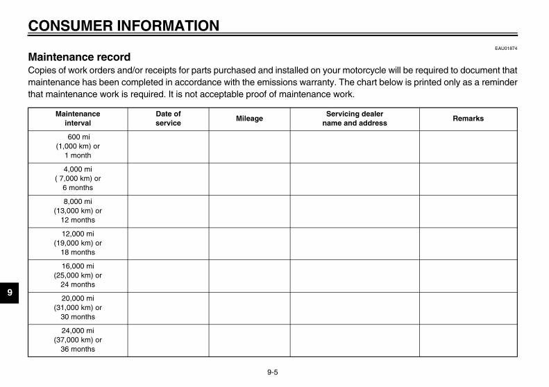
CO
9
EAU01874
MaCo cle will be required to document thatma t below is printed only as a reminderthaCL-04
leress
Remarks
U5SL10.book Page 5 Friday, November 1, 2002 4:33 PM
NSUMER INFORMATION
9-5
intenance record pies of work orders and/or receipts for parts purchased and installed on your motorcyintenance has been completed in accordance with the emissions warranty. The chart maintenance work is required. It is not acceptable proof of maintenance work.E
Maintenanceinterval
Date ofservice
MileageServicing dea
name and addr
600 mi(1,000 km) or
1 month
4,000 mi( 7,000 km) or
6 months
8,000 mi(13,000 km) or
12 months
12,000 mi(19,000 km) or
18 months
16,000 mi(25,000 km) or
24 months
20,000 mi(31,000 km) or
30 months
24,000 mi(37,000 km) or
36 months

MER INFORMATION
9
alerress
Remarks
U5SL10.book Page 6 Friday, November 1, 2002 4:33 PM
CONSU
9-6
28,000 mi(43,000 km) or
42 months
32,000 mi(49,000 km) or
48 months
36,000 mi(55,000 km) or
54 months
40,000 mi(61,000 km) or
60 months
Maintenanceinterval
Date ofservice
MileageServicing de
name and add

CO
9
EAU02918
. ARRANTY
CW-B
U5SL10.book Page 7 Friday, November 1, 2002 4:33 PM
NSUMER INFORMATION
9-7
YAMAHA MOTOR CORPORATION, U.S.ASTREET AND ENDURO MOTORCYCLE LIMITED W
1E

MER INFORMATION
9
CW
U5SL10.book Page 8 Friday, November 1, 2002 4:33 PM
CONSU
9-8
-B2E

CO
9
EAU04965
CW-O
ecreation Interruption Protection extra cost. TRIP gives you up to r occurrence for any reasonable ecause your Yamaha needs ment vehicle rental, emergency
n food and lodging when you are uperb coverage goes into effect S., so it applies to any warranty ered repairs during your entire
red at any authorized Yamaha
sferable to a new owner if you make your Yamaha much more
coverage is only available to d only while your Yamaha is still
Warranty period. So visit your o get all the facts. He can show ct your investment with Yamaha
U5SL10.book Page 9 Friday, November 1, 2002 4:33 PM
NSUMER INFORMATION
9-9
YAMAHA EXTENDED SERVICE (Y.E.S.) 1E
Keep your Yamaha protected even after your warranty expires with genuine Yamaha Extended Service (Y.E.S.).
Y.E.S. is designed and administered by Yamaha Motor Corporation to provide maximum owner satisfaction. You get uninterrupted factory-backed coverage for extra peace of mind.
Y.E.S. is flexible. You choose the plan that’s right foryou: 12 months, 24 months, 36 months or, on certain models, even 48 months beyond your warranty period.
Y.E.S. is designed and administered by the same Yamaha people who handle your warranty – and itshows in the comprehensive coverage benefits. There are no mileage limitations. Coverage isn’t limited to “moving parts” or the “drive train” like many other plans. And Y.E.S. covers manufacturing defects just like the warranty. See the sample contract at your Yamahadealer to see how comforting uninterrupted factory-backed protection can be.
You don’t have to pay anything for covered repairs. There’s no deductible to pay, and repairs aren’t“pro-rated.” You don’t have any “out-of-pocket” expenses for covered repairs.
In addition, Travel and R(TRIP) is included at no $150 reimbursement peexpenses you incur bcovered service: replacetowing, phone calls, eveaway from home. This swhen you purchase Y.E.repairs as well as covY.E.S. plan period.
Y.E.S. coverage is honodealer nationwide.
Y.E.S. coverage is transell or trade-in. That canvaluable!
This excellent Y.E.S. plan Yamaha owners like you, anwithin the Yamaha Limitedauthorized Yamaha dealer tyou how easy it is to proteExtended Service.
MER INFORMATION
9
CW
U5SL10.book Page 10 Friday, November 1, 2002 4:33 PM
CONSU
9-10
-O2E
We urge you to act now. You’ll get the excellent benefits of TRIP coverage right away, and you’ll rest easy knowing you’ll have strong factory-backed protection even after your Yamaha Limited Warranty expires.
A special note:If visiting your dealer isn’t convenient, contact Yamaha with your Primary ID number (your frame number). We’ll be happy to help you get the Y.E.S. coverage you need.
Yamaha Service MarketingP.O. Box 6555Cypress, CA 906301-(866)-YES-EXTD (1-866-937-3983)

D
ce f in
ttakb
akb
akakakakakakak
bnretattoCCows
abels, location ........................................1-7icense plate light bulb, replacing...........6-49uggage strap holders ...........................3-23
ain switch/steering lock .........................3-1aintenance and lubrication, periodic ......6-5aintenance, emission control system.....6-3aintenance, periodic ..............................6-1aintenance record .................................9-5odel label ..............................................9-2ulti-function display................................3-6
eutral indicator light ...............................3-3oise regulation .......................................9-4
il level warning light ...............................3-3
arking.....................................................5-5art locations ...........................................2-1re-operation check list............................4-1
afety defects, reporting ..........................9-3afety information ....................................1-1eats .....................................................3-16
Passenger seat.................................3-17Rider seat .........................................3-16
U5SL10.book Page 1 Friday, November 1, 2002 4:33 PM
10-IN
AAcAirAir
BBaBr
luBr
luBrBrBrBrBrBrBr
CCaCaCaCaCluCluCo
CoCo
in
e pads, checking.............................6-35e pedal............................................3-13e pedal position, adjusting ..............6-34
les, checking and lubricating............6-39ister (for California only)...................6-13.........................................................7-1lytic converter .................................3-16
ch lever............................................3-12ch lever free play, adjusting .............6-33lant ..................................................6-18hanging..........................................6-20hecking ..........................................6-18
lant temperature warning light............3-4lings and panels, removing and talling ................................................6-9
Fuel ....................................................... 3-15Fuel level warning light ............................ 3-2Fuel tank cap......................................... 3-14Fuses, replacing .................................... 6-45
HHandlebar switches ............................... 3-10Headlight bulb, replacing ....................... 6-46Helmet holders ...................................... 3-17High beam indicator light ......................... 3-3Horn switch ........................................... 3-11
IIdentification numbers ............................. 9-1Ignition circuit cut-off system.................. 3-24Indicator and warning lights ..................... 3-2
KKey identification number ........................ 9-1
N
OO
PPPP
SSSS
EX
ssories and replacement parts .......6-32ilter element, checking .....................6-24take duct ........................................6-27
ery ...................................................6-44e and clutch levers, checking and ricating ............................................6-40e and shift pedals, checking and ricating ............................................6-41e fluid, changing .............................6-37e fluid level, checking......................6-36e lever.............................................3-13e light switch (rear), adjusting .........6-34
DDimmer switch....................................... 3-10Drive chain, lubricating .......................... 6-39Drive chain slack ................................... 6-37
Adjusting .......................................... 6-38Checking.......................................... 6-37
EEngine break-in ....................................... 5-4Engine oil and oil filter cartridge ............. 6-14Engine stop switch................................. 3-11Engine trouble warning light .................... 3-3
FFront fork, adjusting............................... 3-19Front fork, checking ............................... 6-42
LLLL
MMMMMMMM
NN

INDEX
Sh
ShShShSidSidSpSpStaStaSteStoStoSuSw
TTaTaThTh
luTirToTroTroTuTuTu
U5SL10.book Page 2 Friday, November 1, 2002 4:33 PM
rage.................................................... 7-4rage compartment ............................ 3-18pporting the motorcycle ..................... 6-49ingarm pivot, lubricating.................... 6-42
chometer ........................................... 3-10il/brake light ....................................... 6-48rottle cable free play, adjusting .......... 6-28rottle grip and cable, checking and bricating............................................ 6-40es ...................................................... 6-29ol kit..................................................... 6-1ubleshooting..................................... 6-55ubleshooting charts .......................... 6-56
rn signal indicator lights ....................... 3-2rn signal light bulb, replacing ............. 6-48rn signal switch.................................. 3-11
ifting .................................................... 5-3Decelerating....................................... 5-4Shift points ......................................... 5-4Starting out and accelerating.............. 5-3
ift pedal ............................................. 3-12ift timing indicator light ......................... 3-4ock absorber assembly, adjusting ..... 3-21estand .............................................. 3-23estand, checking and lubricating....... 6-41ark plugs, checking ........................... 6-12ecifications .......................................... 8-1rting the engine .................................. 5-1rt switch............................................ 3-11ering, checking ................................. 6-43
VValve clearance, adjusting .................... 6-28Vehicle identification number................... 9-1
WWarranty, extended................................. 9-9Warranty limited ...................................... 9-7Wheel bearings, checking ..................... 6-43Wheel (front) ......................................... 6-50
Installing .......................................... 6-51Removing ........................................ 6-50
Wheel (rear) .......................................... 6-53Installing .......................................... 6-54Removing ........................................ 6-53
Wheels.................................................. 6-32
PRINTED IN JAPAN2002.11-7.3×1 CR
(E)
PRINTED ON RECYCLED PAPER YAMAHA MOTOR CO., LTD.
5SL-28199-10LIT-11626-16-45
YZF-R6R(C)
OWNER’S MANUAL


