Module Type Controller SRZ IMS01T11-E1 Thank you for purchasing this RKC product. In order to achieve maximum performance and ensure proper operation of your new instrum ent, carefully read all the instructions in this manual. Please place this manual in a convenient location for easy reference. 1. OUTLINE Using the setting examples below, this secti on explains the configuration when two Z-TIO-C or Z-TIO-D temperature cont rol modules (supporting PLC comm unication) are connected to a MITSUBISHI MELSEC Series programmable controller (PLC). In addition, PLC communication environmental settings are required to communicate with the PLC. The PLC communication enviro nmental settings are set by the host communication, so the host computer and Z- TIO-C or Z-TIO-D modul e must be connected. (This manual is the explanation by the loader communication.) Z-TIO-C or Z-TIO-D module PLC communication RS-485A Personal computer [PLC Setting example] Power supply 24 V DC MITSUBISHI Programmable controller (PLC) USB communication converter COM-K (RKC product) Loader communication The Loader port is only for parameter setup. For the host communication, t he installation, the detail handling procedures and various function settings, please read if nec essary the following separate manuals. • Z-TIO INSTRUCTION MANUAL [for PLC Communication] (IMS01T10-E ): Enclosed with Z-TIO • Z-TIO PLC Communication Quick Instruction Manual [PART 1: Preparation] (IMS01T12-E ): Enclosed with Z-TIO • SRZ Instruction Manual [PLC communication] (IMS01T13-E ): Separate (Download or sold separately) • SRZ Instruction Manual (IMS01T04-E ): Separate (Download or sold separately) The above manuals can be downloaded from our website: URL: http://www.rkcinst.c om/english/manual_load.htm 2. HANDLING PROCEDURES • Communication program preparation • Communication port setting • Connection of loader communication See 6. PLC COMMUNICATION SETTING VIA LOADER COMMUNICATION Mounting and Wiring PLC communication environment setting Communication setting of Z-TIO module Initial setting Data setting See 3. COMMUNICATION SETTING OF Z-TIO MODULE Mount the Z-TIO-C or Z-TIO-D modules and connect the input/output and power supply wiring. See Z-TIO INSTRUCTION MANUAL [for PLC Communication] (IMS01T10-E ) See 6. PLC COMMUNICATION SETTING VIA LOADER COMMUNICATION See 5. WIRING Connection to PLC See Z-TIO PLC Quick Instruction Manual [PART2: Operation] (IMS01T12-E ) PLC setting See 4. PLC COMMUNICATION SETTING See Z-TIO PLC Quick Instruction Manual [PART2: Operation] (IMS01T12-E ) 3. COMMUNICATION SETTING OF Z-TIO MODULE Set communication setting before mounti ng and wiring of the Z-TIO module. Do not separate the module mainframe from the base with the po wer turned on. If so, instrument failure may result. 3.1 Module Address Setting Set an address for the Z-TIO-C or Z-TIO-D module using a small blade screwdriver. • When one module is used, set the module address to 0. • When multiple modules are used, be sure to set one of the modules to module address 0. The module with module address 0 will be the master module. Address setting switch Setting range: 0 to F [0 to 15: Decimal] Factory set value: 0 Setting of address setting switch 0 1 Z-TIO-C/D module 1 Z-TIO-C/D module 2 • To avoid problems or malfunction, do not duplicate an address on the same communication line. • For Modbus, the value obtained by adding "1" to the set address corresponds to the address used for the actual program. 3.2 Protocol Selections and Communication Speed Setting Use the DIP switch on the ri ght side of module to select communication speed, data bit, configuration and protocol. T he data changes become valid when the power is turned on again or when changed to RUN/STOP. DIP switch ON OFF 1 2 3 4 5 6 7 8 ON Module main frame Z-TIO-C/D right side view (The above figure is for the terminal type. However, the switch positions are the same for the connector type.) • Switch No. 8 must be always OFF. Do not set to ON. • When two or more Z-TIO-C or Z-TI O-D modules are connected on the same communication line, the DIP switch settings of all modules must be the same. For communication settings when connected to a different functional module, see the SRZ Instruction Manual [PLC communication] (IMS01T13-E ). Set the DIP switch settings to the same values as the connected PLC. 1 2 Communication speed s p b 0 0 8 4 F F O F F O s p b 0 0 6 9 F F O N O s p b 0 0 2 9 1 N O F F O s p b 0 0 4 8 3 N O N O Factory set value : 19200 bps 3 4 5 Data bit configuration OFF OFF OFF Data 7-bit, without parity, Stop 1-bit 1 OFF ON OFF Data 7-bit, Even parity, Stop 1-bit 1 ON ON OFF Data 7-bit, Odd parity, Stop 1-bit 1 OFF OFF ON Data 8-bit, without parity, Stop 1-bit OFF ON ON Data 8-bit, Even parity, Stop 1-bit 2 ON ON ON Data 8-bit, Odd parity, Stop 1-bit 2 Factory set value: Data 8-bit, without parity 1 When the Modbus communication protocol is selected, this setting becomes invalid. 2 For Modbus communication, this is treated as “Without parity.” 6 7 Communication protocol n o i t a c i n u m m o c C K R F F O F F O s u b d o M F F O N O OFF ON MITSUBISHI MELSEC series special protocol (type 4) A compatible, 1C frame, AnA/AnU CPU common command (QR/QW) QnA compatible, 3C frame, command (0401/1401) ZR register only (AnA/AnU/QnA/Q series) ON ON MITSUBISHI MELSEC series special protocol (type 4) A compatible, 1C frame, ACPU common command (WR/WW) (A series, FX2N 、FX2NC series, FX3U/FX3UC series) Factory set value: Factory set value varies depending on the instrument specification. 4. PLC COMMUNICATION SETTING Sets the communication items of PLC side. (Recommend setting example) The setting item varies depending the PLC. The details of the setting procedure for the PLC, see the instruction manual for the PLC being used. Setting example PLC MITSUBISHI MELSEC series Personal computer Sequencer Programming Software GX Developer (Manufactured by MITSUBISHI) n o i t p i r c s e D m e t I e d o m l o c o t o r p 4 e p y T l o c o t o r P Station number 00 Computer link/multi-drop selection Computer link Communication rate Set the same as Z-TIO-C or Z-TIO-D Operation setting Independent 8 t i b a t a D t u o h t i W t i b y t i r a P 1 t i b p o t S Sum check code Provided Writing during RUN Allowed Setting modification Allowed Termination resistor Connect the termination resistor attached to the PLC 5. WIRING Connect a termination resistor betw een the communication terminals (No.3 and 4) of the module at the end of the communication line from the host computer or PLC. The communication cable must be provided by the customer. 5.1 Connection to PLC Terminal configuration and wiring example The Z-TIO-C/D module has RS-485 communication terminals for RKC communication, Modbus/RTU communication and PLC communication protocol. Communication terminals are on the base side. SDA SG SDB RDA RDB FG PLC MITSUBISHI MELSEC A, AnA, AnU, QnA and Q series 3 4 5 (Base) R1: Termination resistor Example: 120 Ω 1/2 W For the termination resisto r of PLC side, see the PLC Instruction Manual. Communication terminals (RS-485) 3 4 5 Terminal No. Signal name Send data/Receive data Send data/Receive data Signal ground T/R (A) T/R (B) SG Symbol Communication cable T/R (A) T/R (B) SG SG T/R (B) T/R (A) Short wire Wiring example When preparing a ca ble of connecting the MITSUB ISHI MELSEC series to our Z-TIO-C/D module, cross each pair of wires the A and B terminal positions on their terminal boards are not symmetrical. Z-TIO-C or Z-TIO-D module Z-TIO module 16 Connected by the internal communication line RS-485 Shielded twisted pair wire Pair wire SG 5 T/R (A) 3 4 T/R (B) Up to 16 Z-TIO-C/D modules can be connected. R1: Termination resistor (Example: 120 Ω 1/2 W) SG 5 T/R (A) 3 4 T/R (B) (−) (+) (−) (+) (−) (+) (−) (+) PLC MITSUBISHI MELSEC series SDB SDA SG RDB RDA R2 R2: Termination resistor (PLC side) Z-TIO module 1 For the termination resistor of PLC side, see the PLC Instruction Manual. 6. PLC COMMUNICATION ENVIRONMENT SETTING VIA LOADER COMMUNICATION This section explains how to configure t he PLC communication environment settings by loader communication. To perform loader communication, a communication program must be created. 6.1 Preparation of USB Communication Converter To perform loader communication, our converter and a communication cable are required. USB communication converter COM-K (With USB cable) Loader communication cable W-BV-01 [option] 6.2 Preparation of Communication program Refer to the RKC communication protocol or the Modbus communication protocol to create a communication program. For RKC communication or Modbus communication protocol, see SRZ Instruction Manual (IMS01T04-E ). 6.3 Loader Communication Setting For loader communication, set the communication port of the computer to the following values. There are no loader communication settings on the Z-TIO-C/D module side. Communication speed 38400 bps 0 s s e r d d A 1 t i b t r a t S 8 t i b a t a D Parity bit Without parity 1 t i b p o t S Above setting data is fixed. 6.4 Connection of loader communication Connect a USB communication converter COM-K between the personal computer and the Z-TIO-C or Z-TIO-D module. USB communication converter COM-K (RKC product) Connect to USB port of personal computer. Connect to USB connector of COM-K The termination resistor builtin to the COM-K. Loader communication cable (W-BV-01) [option] Connect to loader communication connecter USB cable (Attached to COM-K) Personal computer Z-TIO-C or Z-TIO-D module Connect to loader communication connecter of Z-TIO-C/D module All Rights Reserved, Copyright 2006, RKC INSTRUMENT INC. Z - TIO PLC Communication Quick Instruction Manual [PART1: Preparation] Temperature Control Module [for PLC Communication] CAUTION To prevent electric shock or instrument failure, turn off the power before connecting or disconnecting the instrument and peripheral equipment. ! WARNING (800) 576 - 6308 www.rkc-usa.com Distributed By Inc, RKC
Transcript
Module Type Controller SRZ
IMS01T11-E1
Thank you for purchasing this RKC product. In order to achieve maximum performance and ensure proper operation of your new instrum ent, carefully read all the instructions in this manual. Please place this manual in a convenient location for easy reference.
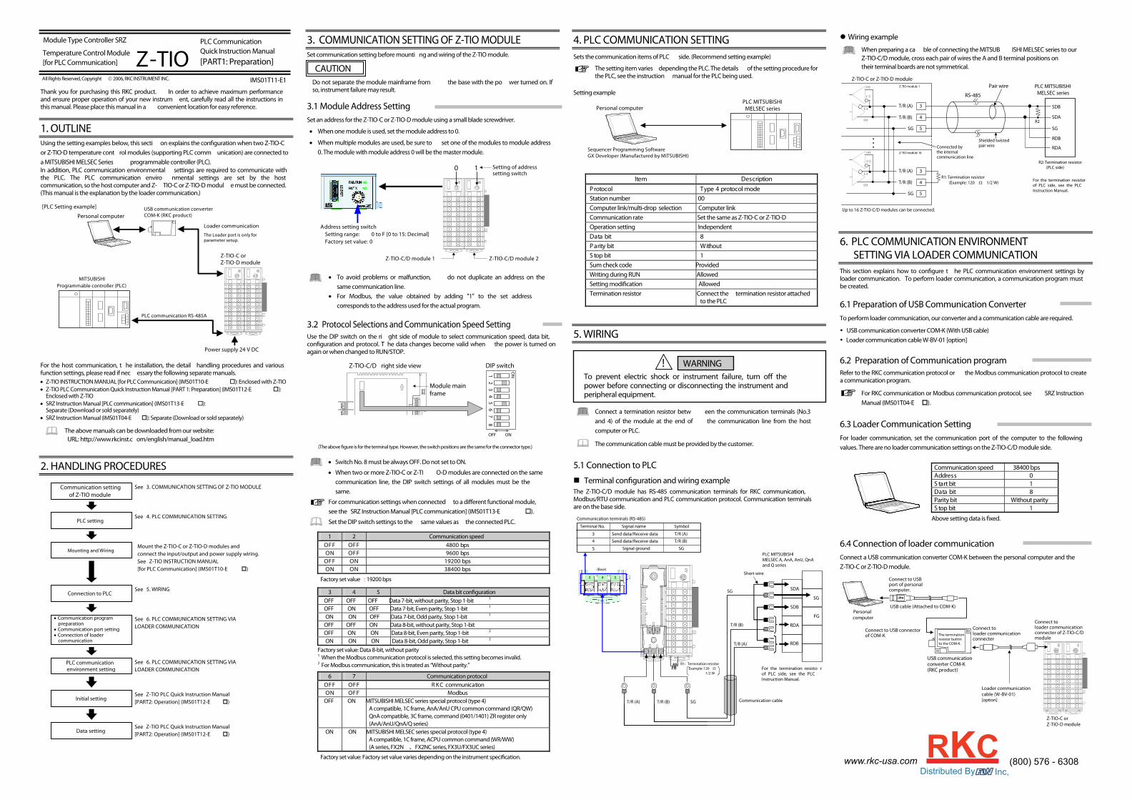
1. OUTLINE Using the setting examples below, this secti on explains the conguration when two Z-TIO-C or Z-TIO-D temperature cont rol modules (supporting PLC comm unication) are connected to a MITSUBISHI MELSEC Series programmable controller (PLC). In addition, PLC communication environmental settings are required to communicate with the PLC. The PLC communication enviro nmental settings are set by the host communication, so the host computer and Z- TIO-C or Z-TIO-D modul e must be connected. (This manual is the explanation by the loader communication.)
Z-TIO-C or Z-TIO-D module
PLC communication RS-485A
Personal computer
[PLC Setting example]
Power supply 24 V DC
MITSUBISHI Programmable controller (PLC)
USB communication converter COM-K (RKC product)
Loader communication The Loader port is only for parameter setup.
For the host communication, t he installation, the detail handling procedures and various function settings, please read if nec essary the following separate manuals. • Z-TIO INSTRUCTION MANUAL [for PLC Communication] (IMS01T10-E ): Enclosed with Z-TIO • Z-TIO PLC Communication Quick Instruction Manual [PART 1: Preparation] (IMS01T12-E ):
Separate (Download or sold separately) • SRZ Instruction Manual (IMS01T04-E ): Separate (Download or sold separately)
The above manuals can be downloaded from our website: URL: http://www.rkcinst.c om/english/manual_load.htm
2. HANDLING PROCEDURES
• Communication program preparation
• Communication port setting • Connection of loader
communication
See 6. PLC COMMUNICATION SETTING VIA LOADER COMMUNICATION
Mounting and Wiring
PLC communication environment setting
Communication setting of Z-TIO module
Initial setting
Data setting
See 3. COMMUNICATION SETTING OF Z-TIO MODULE
Mount the Z-TIO-C or Z-TIO-D modules and connect the input/output and power supply wiring. See Z-TIO INSTRUCTION MANUAL [for PLC Communication] (IMS01T10-E )
See 6. PLC COMMUNICATION SETTING VIA LOADER COMMUNICATION
See 5. WIRING Connection to PLC
See Z-TIO PLC Quick Instruction Manual [PART2: Operation] (IMS01T12-E )
PLC setting See 4. PLC COMMUNICATION SETTING
See Z-TIO PLC Quick Instruction Manual [PART2: Operation] (IMS01T12-E )
3. COMMUNICATION SETTING OF Z-TIO MODULE Set communication setting before mounti ng and wiring of the Z-TIO module.
Do not separate the module mainframe from the base with the po wer turned on. If so, instrument failure may result.
3.1 Module Address Setting Set an address for the Z-TIO-C or Z-TIO-D module using a small blade screwdriver.
• When one module is used, set the module address to 0.
• When multiple modules are used, be sure to set one of the modules to module address 0. The module with module address 0 will be the master module.
Address setting switch Setting range: 0 to F [0 to 15: Decimal] Factory set value: 0
Setting of addresssetting switch
0 1
Z-TIO-C/D module 1 Z-TIO-C/D module 2
• To avoid problems or malfunction, do not duplicate an address on the same communication line.
• For Modbus, the value obtained by adding "1" to the set address corresponds to the address used for the actual program.
3.2 Protocol Selections and Communication Speed Setting Use the DIP switch on the ri ght side of module to select communication speed, data bit, conguration and protocol. T he data changes become valid when the power is turned on again or when changed to RUN/STOP.
DIP switch
ONOFF
12
34
56
78
ON
Module main frame
Z-TIO-C/D right side view
(The above gure is for the terminal type. However, the switch positions are the same for the connector type.)
• Switch No. 8 must be always OFF. Do not set to ON.
• When two or more Z-TIO-C or Z-TI O-D modules are connected on the same communication line, the DIP switch settings of all modules must be the same.
For communication settings when connected to a dierent functional module, see the SRZ Instruction Manual [PLC communication] (IMS01T13-E ).
Set the DIP switch settings to the same values as the connected PLC.
1 2 Communication speed spb 0084 FFOFFO spb 0069 FFO NO spb 00291 NOFFO spb 00483 NO NO
Factory set value : 19200 bps
3 4 5 Data bit conguration OFF OFF OFF Data 7-bit, without parity, Stop 1-bit 1 OFF ON OFF Data 7-bit, Even parity, Stop 1-bit 1 ON ON OFF Data 7-bit, Odd parity, Stop 1-bit 1
OFF OFF ON Data 8-bit, without parity, Stop 1-bit OFF ON ON Data 8-bit, Even parity, Stop 1-bit 2 ON ON ON Data 8-bit, Odd parity, Stop 1-bit 2
Factory set value: Data 8-bit, without parity 1 When the Modbus communication protocol is selected, this setting becomes invalid. 2 For Modbus communication, this is treated as “Without parity.”
6 7 Communication protocol
noitacinummoc CKR FFOFFO subdoM FFO NO
OFF ON MITSUBISHI MELSEC series special protocol (type 4) A compatible, 1C frame, AnA/AnU CPU common command (QR/QW)QnA compatible, 3C frame, command (0401/1401) ZR register only (AnA/AnU/QnA/Q series)
ON ON MITSUBISHI MELSEC series special protocol (type 4) A compatible, 1C frame, ACPU common command (WR/WW) (A series, FX2N 、FX2NC series, FX3U/FX3UC series)
Factory set value: Factory set value varies depending on the instrument specication.
4. PLC COMMUNICATION SETTING Sets the communication items of PLC side. (Recommend setting example)
The setting item varies depending the PLC. The details of the setting procedure for the PLC, see the instruction manual for the PLC being used.
Setting example
PLC MITSUBISHI MELSEC series Personal computer
Sequencer Programming Software GX Developer (Manufactured by MITSUBISHI)
noitpircseD metI
edom locotorp 4 epyT locotorPStation number 00 Computer link/multi-drop selection Computer link Communication rate Set the same as Z-TIO-C or Z-TIO-D Operation setting Independent
8 tib ataD tuohtiW tib ytiraP
1 tib potSSum check code Provided Writing during RUN Allowed Setting modication Allowed Termination resistor Connect the termination resistor attached
to the PLC
5. WIRING
Connect a termination resistor betw een the communication terminals (No.3 and 4) of the module at the end of the communication line from the host computer or PLC.
The communication cable must be provided by the customer.
5.1 Connection to PLC
Terminal conguration and wiring example The Z-TIO-C/D module has RS-485 communication terminals for RKC communication, Modbus/RTU communication and PLC communication protocol. Communication terminals are on the base side.
SDA
SG
SDB
RDA
RDB
FG
PLC MITSUBISHI MELSEC A, AnA, AnU, QnA and Q series
3 4 5
(Base)
R1: Termination resistor Example: 120 Ω
1/2 W For the termination resisto r of PLC side, see the PLC Instruction Manual.
Communication terminals (RS-485)
3
4
5
Terminal No. Signal name
Send data/Receive data
Send data/Receive data
Signal ground
T/R (A)
T/R (B)
SG
Symbol
Communication cableT/R (A) T/R (B) SG
SG
T/R (B)
T/R (A)
Short wire
Wiring example
When preparing a ca ble of connecting the MITSUB ISHI MELSEC series to our Z-TIO-C/D module, cross each pair of wires the A and B terminal positions on their terminal boards are not symmetrical.
Z-TIO-C or Z-TIO-D module
Z-TIO module 16
Connected by the internal communication line
RS-485
Shielded twistedpair wire
Pair wire
SG 5
T/R (A) 3
4 T/R (B)
Up to 16 Z-TIO-C/D modules can be connected.
R1: Termination resistor (Example: 120 Ω 1/2 W)
SG 5
T/R (A) 3
4 T/R (B)
(−)
(+)
(−)
(+)
(−)
(+)
(−)
(+)
PLC MITSUBISHI MELSEC series
SDB
SDA
SG
RDB
RDA
R2
R2: Termination resistor (PLC side)
Z-TIO module 1
For the termination resistor of PLC side, see the PLC Instruction Manual.
6. PLC COMMUNICATION ENVIRONMENT SETTING VIA LOADER COMMUNICATION
This section explains how to congure t he PLC communication environment settings by loader communication. To perform loader communication, a communication program must be created. 6.1 Preparation of USB Communication Converter To perform loader communication, our converter and a communication cable are required.
USB communication converter COM-K (With USB cable) Loader communication cable W-BV-01 [option]
6.2 Preparation of Communication program Refer to the RKC communication protocol or the Modbus communication protocol to create a communication program.
For RKC communication or Modbus communication protocol, see SRZ Instruction Manual (IMS01T04-E ).
6.3 Loader Communication Setting For loader communication, set the communication port of the computer to the following values. There are no loader communication settings on the Z-TIO-C/D module side.
Communication speed 38400 bps
0 sserddA 1 tib tratS 8 tib ataD
Parity bit Without parity 1 tib potS
Above setting data is xed.
6.4 Connection of loader communication Connect a USB communication converter COM-K between the personal computer and the Z-TIO-C or Z-TIO-D module.
USB communication converter COM-K (RKC product)
Connect to USB port of personal computer.
Connect to USB connector of COM-K The termination
resistor builtin to the COM-K.
Loader communicationcable (W-BV-01) [option]
Connect toloader communicationconnecter
USB cable (Attached to COM-K)Personal computer
Z-TIO-C or Z-TIO-D module
Connect toloader communicationconnecter of Z-TIO-C/Dmodule
All Rights Reserved, Copyright 2006, RKC INSTRUMENT INC.
Z-TIO PLC Communication Quick Instruction Manual [PART1: Preparation]
Temperature Control Module [for PLC Communication]
CAUTION
To prevent electric shock or instrument failure, turn o the power before connecting or disconnecting the instrument and peripheral equipment.
! WARNING
(800) 576 - 6308www.rkc-usa.comDistributed By Inc,
Modbus is a registered trademark of Schneider Electric.The name of each programmable controller (PLC) means the products of each manufacturer. Company names and product names used in this manual are the trademarks or registeredtrademarks of the respective companies.
6.5. PLC Communication Environment Setting The PLC communication environmental settings must be made to perform PLC communication. The system data settings are made by the loader communication. 1. Turn on the power of the Z-TIO-C or Z-TIO-D module.
(PLC power is off.)
2. On the personal computer, set the communication data of the PLC communication environment indicated below.
3. When the settings for the communication data of the PLC communication environment are completed, turn the power of the Z-TIO-C/D module off, and then turn it on again. When the power is turned ON, the changed system data values are enabled.
Set the communication data for each module. After completing the communication settings of the first module, connect the loader communication cable to the next module and set the PLC communication environment.
Loader communication cable (W-BV-01) [Option]
Connect to loader communication cable of next module.
Z-TIO-C or Z-TIO-D module
Communication data list (PLC communication environment) RO: Read only data R/W: Read and Write data
Modbus register address Name
RKC Iden- tifier HEX DEC
Digits Attri- bute Data range Factory
set value
Station number QV 0164 356 7 R/W 0 to 31
Set the PLC station number. Set it to the same number as the PLC.
0
PC number QW 0165 357 7 R/W 0 to 255
Set the PLC PC number. Set it to the same number as the PLC. Set all Z-TIO-C/D modules to the same values.
255
Register type QZ 0166 358 7 R/W 0: D register 1: R register 2: W register 3: ZR register
Method of specifying consecutive numbers when 32767 of R register is exceeded. When the ZR register is selected, QnA compatible 3C frame communication is used.
Set the register types used in PLC communication.
0
Register start number (High-order 4-bit)
QS 0167 359 7 R/W 0 to 15
Set the start number of the register of system data used in PLC communication. Set this if the register address 65535 is exceeded in the ZR register.
0
Register start number (Low-order 16-bit)
QX 0168 360 7 R/W 0 to 9999 A compatible, 1C frame, ACPU common command (WR/WW)
0 to 65535 A compatible 1C frame AnA/AnUCPU common command (QR/QW), QnA compatible 3C frame
Set the start number of the register of system data used in PLC communication. System data is required to perform PLC communication. The system data occupies ten PLC registers.
1000
Modbus
register address Name RKC Iden- tifier HEX DEC
Digits Attri- bute Data range Factory
set value
Monitor item register bias
R3 0169 361 7 R/W 10 to 9999 A compatible, 1C frame, ACPU common command (WR/WW)
10 to 65535 A compatible 1C frame AnA/AnUCPU common command (QR/QW), QnA compatible 3C frame
Set the start number of the register of monitor group communication data. A bias is applied to the register start number. The factory set value for the register bias is 10, and thus the register start number of the monitor group is D01010. Equation for calculating: Register start number of monitor group = Register start number + Monitor item register bias
10
Setting item register bias
R4 016A 362 7 R/W 0, 10 to 9999 A compatible, 1C frame, ACPU common command (WR/WW)
0, 10 to 65535 A compatible 1C frame AnA/AnUCPU common command (QR/QW), QnA compatible 3C frame
Set the start number of the register of setting group communication data. When set to 0 to 9 In the monitor group, the register start number of the setting group is set after the communication data of the last address.
When set to 10 or more A bias is applied to the register start number of the system data. If set to 10 or greater, take care that overlapping of the communication data of the monitor group and the register address does not occur. Equation for calculating: Register start number of setting group = Register start number + Setting item register bias
0
Monitor item selection
R6 016C 364 7 R/W 0 to 65535 Select the communication data of monitor group. The selected communication data only performs PLC communication. Convert binary to decimal and configure the setting. (See Table 1)
33535
Setting item selection
R7 016D ⋅ ⋅ ⋅ 0170
365 ⋅ ⋅ ⋅ 368
7 R/W 0 to 65535 Select the communication data of setting group. The selected communication data only performs PLC communication. Convert binary to decimal and configure the setting. (See Table 2)
(A) 62427(B) 15583(C) 512 (D) 512
Z-TIO module link recognition time
QT 0171 369 7 R/W 0 to 255 seconds When connecting two or more Z-TIO-C/D module, set the time required until a module after the second module is recognized. Set this item to the master module (address 0).
5
PLC scanning time
VT 0172 370 7 R/W 0 to 3000 ms Set the time of waiting for a response from the PLC. Usually, no factory set values are necessary to be changed.
255
PLC communication start time
R5 0173 371 7 R/W 1 to 255 seconds Time until communication with the PLC starts is set after the power is turned on.
5
Slave register bias
R8 0175 373 7 R/W 0 to 65535 When connecting two or more Z-TIO-C/D module, a bias is set for the register addresses of each module so that no address duplication occurs. Set bias enable/disable with the address setting switch. When set the address setting switch to 0: Bias disabled
When set the address setting switch to other than 0: Bias enabled Equation for calculating: Slave register start number = Register start number + (Address setting switch) × Slave register bias
150
Modbus
register addressName RKCIden-tifier HEX DEC
Digits Attri-bute Data range Factory
set value
Interval time ZX 035B 859 7 R/W 0 to 250 ms
On some PLC models, the interval time must be set or the PLC will not be able to respond.
If communication does not take place correctly on an older MELSEC A Series model, set the interval time to 30 milliseconds or more.
Interval time is the engineering setting data. When the Z-TIO module of setting data is stopped, write is possible.
10
Table 1: Monitor item selection (Communication data of monitor group) Communication data of monitor group is assigned as a bit image in binary numbers. Set decimal-converted values.
Factory set value Bit Communication data (Monitor item) Number of
data Binary Decimal 0 Measured value (PV) 4 1 1 Comprehensive event state 4 1 2 Operation mode state monitor 4 1 3 Error code 4* 1 4 Manipulated output value (MV) monitor [heat-side] ♣ 4 1 5 Manipulated output value (MV) monitor [cool-side] ♣ 4 1 6 Current transformer (CT) input value monitor 4 1 7 Set value (SV) monitor 4 1 33535 8 Remote setting (RS) input value monitor 4 0 9 Output state monitor 4* 1 10 Memory area soak time monitor 4 0 11 Integrated operating time monitor 4* 0 12 Holding peak value ambient temperature monitor 4 0 13 Backup memory state monitor 4* 0 14 Logic output monitor 4* 0 15 Memory area number monitor 4 1
♣ When heat/cool control or position proportioning control is performed, there will be communication data (indicated by ♣ in the name column) for which the 2nd channel and 4th channel will be invalid. [Read is possible (0 is shown), but the result of Write is disregarded.]
* Occupies four PLC registers, however, the actual number of data items is 1 (data units are modules), and thus only the data of CH1 is effective.
The selected communication data is justified upward in the PLC register.
Table 2: Setting item selection (Communication data of Setting group) Communication data of setting group is assigned as a bit image in binary numbers. Set decimal-converted values in the setting columns of (A) ch1 to (D) ch4. (A) Setting column of ch1
Factory set value Bit Item
number Number of data (Setting item) Number of data Binary Decimal
0 1 PID/AT transfer 4 1 1 2 Auto/Manual transfer 4 1 2 3 Remote/Local transfer 4 0 3 4 RUN/STOP transfer 4* 1 4 5 Memory area transfer 4 1 5 6 Interlock release 4 0 6 7 Event 1 set value (EV1) 4 1 7 8 Event 2 set value (EV2) 4 1 62427 8 9 Event 3 set value (EV3) 4 1 9 10 Event 4 set value (EV4) 4 1 10 11 Control loop break alarm (LBA) time 4 0 11 12 LBA deadband 4 0 12 13 Set value (SV) 4 1 13 14 Proportional band [heat-side] ♣ 4 1 14 15 Integral time [heat-side] ♣ 4 1 15 16 Derivative time [heat-side] ♣ 4 1
♣ When heat/cool control or position proportioning control is performed, there will be communication data (indicated by ♣ in the name column) for which the 2nd channel and 4th channel will be invalid. [Read is possible (0 is shown), but the result of Write is disregarded.]
* Occupies four PLC registers, however, the actual number of data items is 1 (data units are modules), and thus only the data of CH1 is effective. Parameters which can be used in multi-memory area function
The selected communication data is justified upward in the PLC register.
(B) Setting column of ch2
Factory set value Bit Item number Number of data (Setting item) Number of
data Binary Decimal0 17 Control response parameter ♣ 4 1 1 18 Proportional band [cool-side] ♣ 4 1 2 19 Integral time [cool-side] ♣ 4 1 3 20 Derivative time [cool-side] ♣ 4 1 4 21 Overlap/Deadband ♣ 4 1 5 22 Manual reset 4 0 6 23 Setting change rate limiter (up) 4 1 7 24 Setting change rate limiter (down) 4 1 15583 8 25 Area soak time 4 0 9 26 Link area number 4 0 10 27 Heater break alarm (HBA) set value 4 1 11 28 Heater break determination point 4 1 12 29 Heater melting determination point 4 1 13 30 PV bias 4 1 14 31 PV digital filter 4 0 15 32 PV ratio 4 0
♣ When heat/cool control or position proportioning control is performed, there will be communication data (indicated by ♣ in the name column) for which the 2nd channel and 4th channel will be invalid. [Read is possible (0 is shown), but the result of Write is disregarded.] Parameters which can be used in multi-memory area function
(C) Setting column of ch3
Factory set value Bit Item number Number of data (Setting item) Number of
data Binary Decimal0 33 PV low input cut-off 4 0 1 34 RS bias 4 0 2 35 RS digital filter 4 0 3 36 RS ratio 4 0 4 37 Output distribution selection 4 0 5 38 Output distribution bias 4 0 6 39 Output distribution ratio 4 0 7 40 Proportional cycle time 4 0 512 8 41 Minimum ON/OFF time of proportioning cycle 4 0 9 42 Manual manipulated output value ♣ 4 1 10 43 Area soak time stop function 4 0 11 44 EDS mode (for disturbance 1) 4 0 12 45 EDS mode (for disturbance 2) 4 0 13 46 EDS value 1 (for disturbance 1) 4 0 14 47 EDS value 1 (for disturbance 2) 4 0 15 48 EDS value 2 (for disturbance 1) 4 0
♣ When heat/cool control or position proportioning control is performed, there will be communication data (indicated by ♣ in the name column) for which the 2nd channel and 4th channel will be invalid. [Read is possible (0 is shown), but the result of Write is disregarded.]
(D) Setting column of ch4
Factory set value Bit Item number Number of data (Setting item) Number of
data Binary Decimal0 49 EDS value 2 (for disturbance 2) 4 0 1 50 EDS transfer time (for disturbance 1) 4 0 2 51 EDS transfer time (for disturbance 2) 4 0 3 52 EDS action time (for disturbance 1) 4 0 4 53 EDS action time (for disturbance 2) 4 0 5 54 EDS action wait time (for disturbance 1) 4 0 6 55 EDS action wait time (for disturbance 2) 4 0 7 56 EDS value learning times 4 0 512 8 57 EDS start signal 4 0 9 58 Operation mode 4 1 10 59 Startup tuning (ST) 4 0 11 60 Automatic temperature rise learning 4 0 12 61 Communication switch for logic 4* 0 13 62 Unused 4 0 14 63 Unused 4 0 15 64 Unused 4 0
* Occupies four PLC registers, however, the actual number of data items is 1 (data units are modules), and thus only the data of CH1 is effective.
The selected communication data is justified upward in the PLC register.