BeBeC-2014-20 LOW COST BEAM FORMING SOLUTION FOR A DEVELOPING COUNTRY Zair Asrar Bin Ahmad * Raja Ishak Bin Raja Hamzah † February 12, 2014 ABSTRACT Beamforming is an effective method for sound localization problem. In developing coun- tries like Malaysia, most of the acoustic and beamforming equipment is typically supplied by established United States or European manufacturers. They are very expensive equip- ment with cost comparable to our houses. Only universities aided with special grants from the government can afford it. Even the basic building block of a beamforming system, the microphone is very expensive, more than our monthly salary. Armed with internet, a low cost microphone and beamforming system is being developed in the Faculty of Mechanical Engineering, Universiti Teknologi Malaysia. This is our attempt to start the open hardware movement here which should follow the open source (software) movement that is being widely embraced worldwide. Our microphones and beamforming system are developed using the available resources in our university. 1 INTRODUCTION The detection of sound sources was usually done by hand with level measuring instruments or sound intensity probes. This manual scanning can nowadays be replaced by stationary arrays of microphones that allow the examination of complete structures within one measurement. The output of such an array usually results in a noise map, which can be overlaid on a digital photo of the test object. The noise measurement can be directly compared with a visual image of the object, thus significantly facilitating the interpretation of the acoustic data. Unfortunately, commercially available microphone arrays are rather costly and hardly affordable, especially for third world universities like ours. For this reason we started to consider building such a microphone array by ourselves. * Faculty of Mechanical Engineering, Universiti Teknologi Malaysia, 81310 Johor Bahru, Johor, Malaysia, [email protected]† Faculty of Mechanical Engineering, Universiti Teknologi Malaysia, 81310 Johor Bahru, Johor, Malaysia, [email protected]1
Transcript
BeBeC-2014-20
LOW COST BEAM FORMING SOLUTIONFOR A DEVELOPING COUNTRY
Zair Asrar Bin Ahmad∗ Raja Ishak Bin Raja Hamzah†
February 12, 2014
ABSTRACT
Beamforming is an effective method for sound localization problem. In developing coun-tries like Malaysia, most of the acoustic and beamforming equipment is typically suppliedby established United States or European manufacturers. They are very expensive equip-ment with cost comparable to our houses. Only universities aided with special grants fromthe government can afford it. Even the basic building block of a beamforming system, themicrophone is very expensive, more than our monthly salary. Armed with internet, a lowcost microphone and beamforming system is being developed in the Faculty of MechanicalEngineering, Universiti Teknologi Malaysia. This is our attempt to start the open hardwaremovement here which should follow the open source (software) movement that is beingwidely embraced worldwide. Our microphones and beamforming system are developedusing the available resources in our university.
1 INTRODUCTION
The detection of sound sources was usually done by hand with level measuring instruments orsound intensity probes. This manual scanning can nowadays be replaced by stationary arrays ofmicrophones that allow the examination of complete structures within one measurement. Theoutput of such an array usually results in a noise map, which can be overlaid on a digital photoof the test object. The noise measurement can be directly compared with a visual image ofthe object, thus significantly facilitating the interpretation of the acoustic data. Unfortunately,commercially available microphone arrays are rather costly and hardly affordable, especiallyfor third world universities like ours. For this reason we started to consider building such amicrophone array by ourselves.
∗Faculty of Mechanical Engineering, Universiti Teknologi Malaysia, 81310 Johor Bahru, Johor, Malaysia,[email protected]
†Faculty of Mechanical Engineering, Universiti Teknologi Malaysia, 81310 Johor Bahru, Johor, Malaysia,[email protected]
1
5th Berlin Beamforming Conference 2014 Z.A.B. Ahmad and R.I.B. Raja Hamzah
The lab equipment in Malaysian universities are sources from well known equipment man-ufactures coming from western companies i.e United States and European countries. Theseinclude Bruel & Kjær, National Instruments, Dewetron, GRAS and PCB Piezotronics. Thesame can be said for our Noise and Vibration Lab at Universiti Teknologi Malaysia. Theseequipment are nonetheless good and robust. However, they are very expensive which requirespecial budget from the government that is hard to get. Furthermore, the situation get worseas the equipment cannot be bought directly from the manufacturer overseas. The procurementprocess need to be made through multiple international and local distributors that markup theprice considerably.
In our lab, there is only a few 1/2 inch GRAS microphones. These are our prized possessionsuch that students rarely had a chance to use them. Fearing that the students might damagethem, handling is done mostly by our technicians. As the number of microphones are verylimited, having a beam forming array is almost out of our mind. Recent visits by Bruel &Kjær local distributor indicates that a beam forming array system cost at least more than half amillion Malaysian Ringgit (RM) equivalent to a couple of hundred thousand Euros. Even theimpedance tube (with only two microphones) cost about RM400,000. Therefore, alternativecheaper and affordable solutions are badly needed for us.
2 IDEAS FOR THE PROJECT
We have been inspired by Bischof [2] that has developed a beam forming array system throughjunior year student projects in a university in Graz, Austria. The high cost of the commercialbeam forming system is one of his main motivation for the project which is similar to ours.They have used microphones from ROGA Instruments while the beam forming algorithm isdone using Matlab. We are adopting the same approach but we need to do it by using our ownmicrophones instead. Even the low cost ROGA Instruments microphones is still expensive forus, as a large quantity of microphone is needed in a beam forming array.
An interesting statement in Bischof’s work is that the ROGA Instruments microphone isactually an electret microphone. After doing some market research in Malaysia, we can getan electret microphone component from electronic shops for just RM1 (roughly equivalent toe0.25). The challenge for us is how to get these cheap electret microphones to work as good asour expensive GRAS microphone.
They are many previous researchers who are also attracted by the idea of using cheap electretmicrophone element in beamforming array especially for aeroacoustic applications [4–6]. How-ever, their electret microphone element is powered using external power source [1, 6]. In thiscontribution, we are using electret microphone element with ICP circuit. These microphoneswould then be connected to available DAQ cards in our lab to form a beamforming array sys-tem. The beamforming algorithm is made using Matlab. Finally, the acoustic imaging result ofour proof of concept low cost beamforming system is presented.
2
5th Berlin Beamforming Conference 2014 Z.A.B. Ahmad and R.I.B. Raja Hamzah
3 IMPLEMENTATION
3.1 Hardware
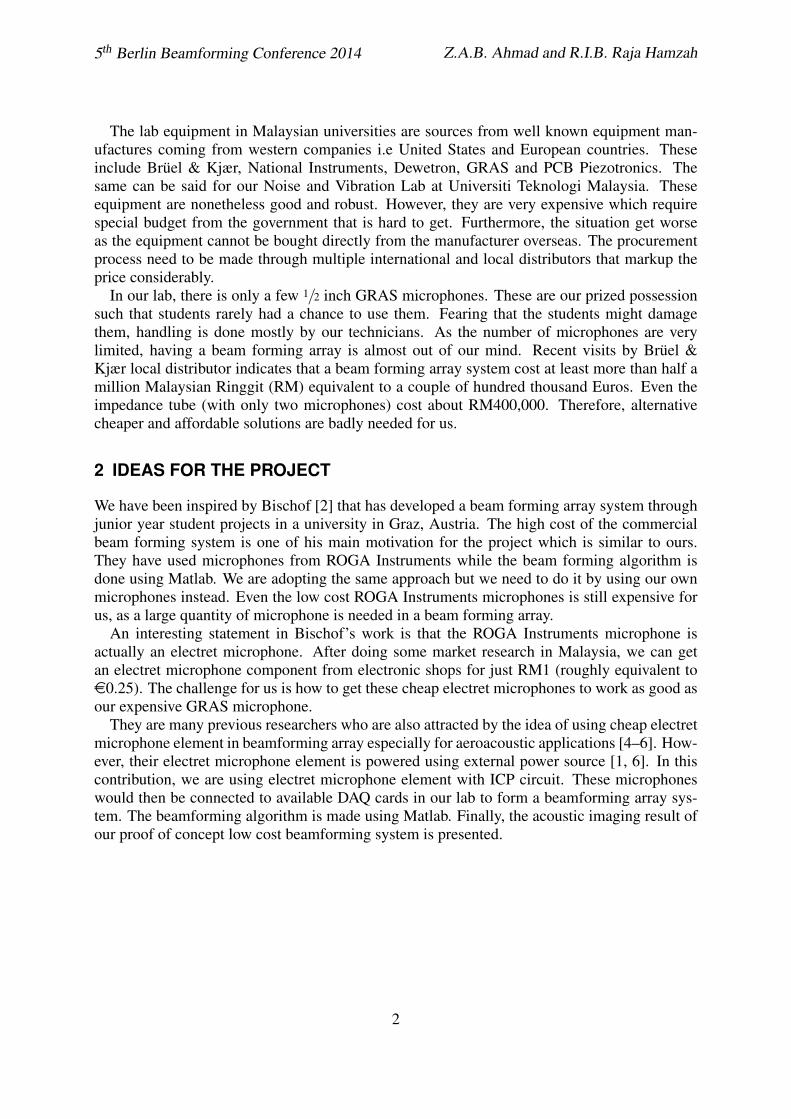
The electret microphone component requires power to operate. Connecting them directly toa sound card is one of the option as the sound card can power the microphone component aswell as boost the sound output. However, the SNR is still low. Another alternative for us is touse the available DAQ card in our lab which is the NI-PCI 4472 card. This card has a featureto turn on IEPE/ICP (constant current source) at the input channel. This will power IEPEmicrophone attached to the card. Therefore, we need to make an IEPE microphone using theelectret microphone component. A way to do this has been suggested in [3]. The constructedmicrophone is shown in Figure 1.
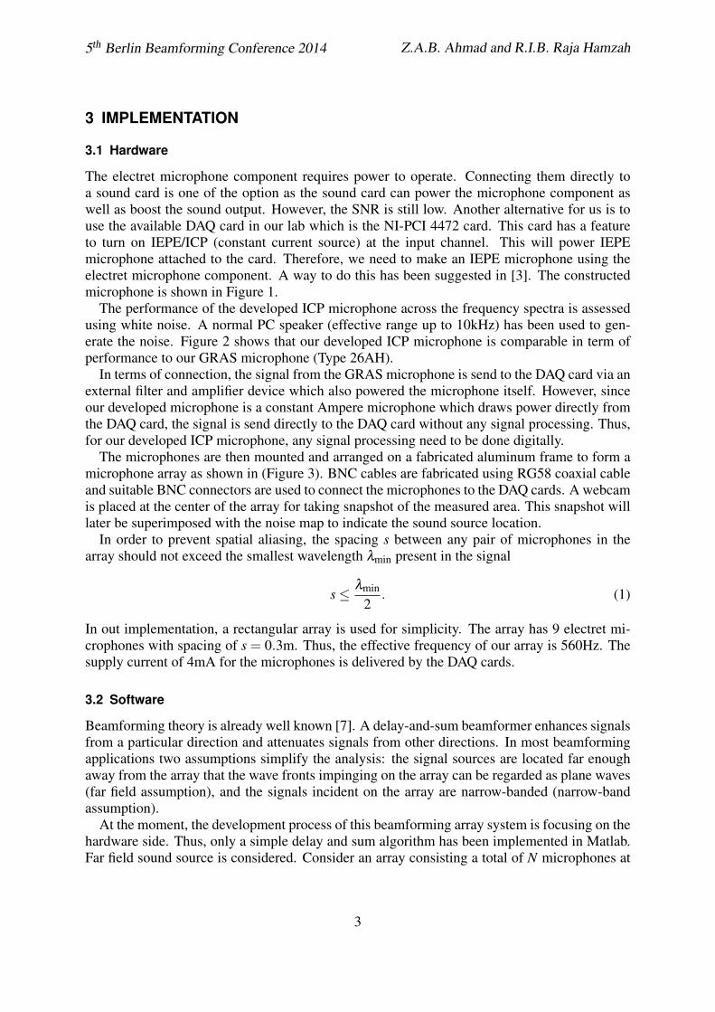
The performance of the developed ICP microphone across the frequency spectra is assessedusing white noise. A normal PC speaker (effective range up to 10kHz) has been used to gen-erate the noise. Figure 2 shows that our developed ICP microphone is comparable in term ofperformance to our GRAS microphone (Type 26AH).
In terms of connection, the signal from the GRAS microphone is send to the DAQ card via anexternal filter and amplifier device which also powered the microphone itself. However, sinceour developed microphone is a constant Ampere microphone which draws power directly fromthe DAQ card, the signal is send directly to the DAQ card without any signal processing. Thus,for our developed ICP microphone, any signal processing need to be done digitally.
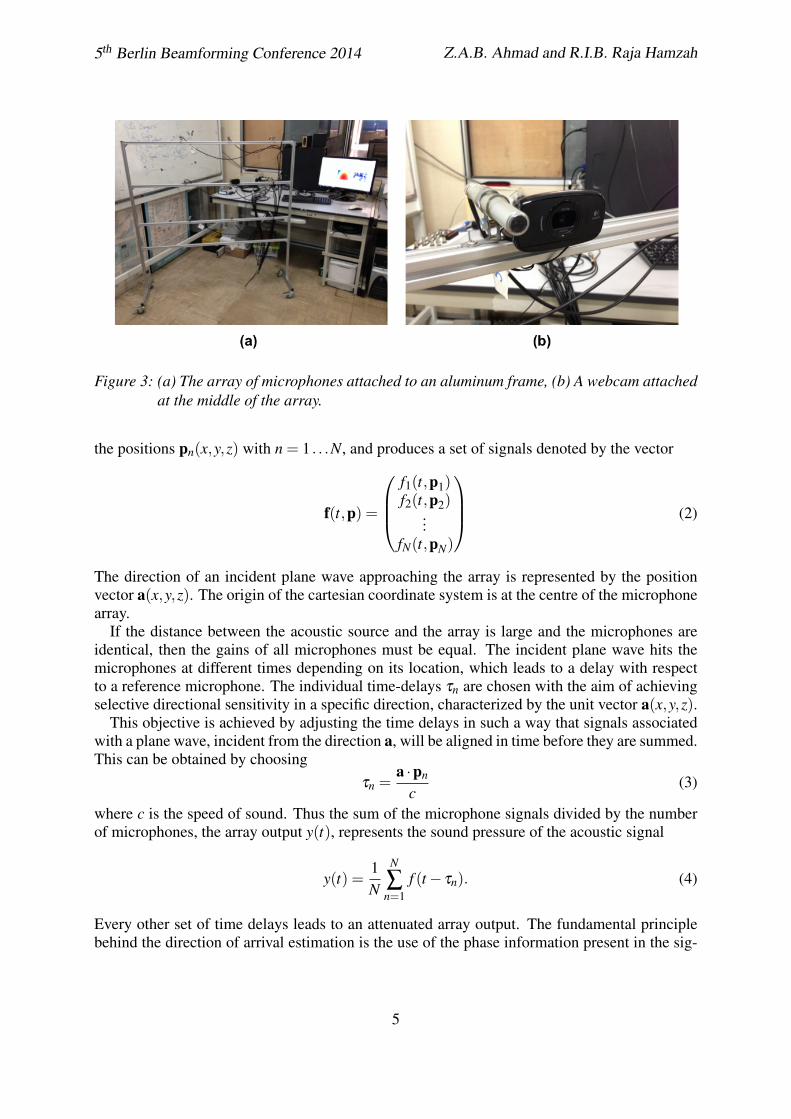
The microphones are then mounted and arranged on a fabricated aluminum frame to form amicrophone array as shown in (Figure 3). BNC cables are fabricated using RG58 coaxial cableand suitable BNC connectors are used to connect the microphones to the DAQ cards. A webcamis placed at the center of the array for taking snapshot of the measured area. This snapshot willlater be superimposed with the noise map to indicate the sound source location.
In order to prevent spatial aliasing, the spacing s between any pair of microphones in thearray should not exceed the smallest wavelength λmin present in the signal
s ≤ λmin
2. (1)
In out implementation, a rectangular array is used for simplicity. The array has 9 electret mi-crophones with spacing of s = 0.3m. Thus, the effective frequency of our array is 560Hz. Thesupply current of 4mA for the microphones is delivered by the DAQ cards.
3.2 Software
Beamforming theory is already well known [7]. A delay-and-sum beamformer enhances signalsfrom a particular direction and attenuates signals from other directions. In most beamformingapplications two assumptions simplify the analysis: the signal sources are located far enoughaway from the array that the wave fronts impinging on the array can be regarded as plane waves(far field assumption), and the signals incident on the array are narrow-banded (narrow-bandassumption).
At the moment, the development process of this beamforming array system is focusing on thehardware side. Thus, only a simple delay and sum algorithm has been implemented in Matlab.Far field sound source is considered. Consider an array consisting a total of N microphones at
3
5th Berlin Beamforming Conference 2014 Z.A.B. Ahmad and R.I.B. Raja Hamzah
3k! 100!
BC559
BNCconnector
Microphonebody
Microphonecapsule
(a) (b)
Figure 1: (a) The inner components of the ICP microphone shown next to the assembled micro-phone in the aluminum tube, (b) Schematics of the ICP microphone circuit.
t [s]
Rec
-0.0
221
-0.0
012
0.01
96G
RA
S m
ic; -
[V]
3.2 3.2 3.2 3.2 3.3
E
t [s]
Rec
-289
.8-1
5.7
258.
4IC
P m
ic; -
[mV
]
3.2 3.2 3.2 3.2 3.3
E
f [H
z]
CPB
08.
0E-4
1.6E
-3G
RA
S m
ic; -
[V]
10 100 1000 10000 f [H
z]
CPB
06
1218
24IC
P m
ic; -
[mV
]
10 100 1000 10000
Figure 2: Comparison between GRAS microphone and our ICP microphone in time domain and1/24 octave band for white noise.
4
5th Berlin Beamforming Conference 2014 Z.A.B. Ahmad and R.I.B. Raja Hamzah
Figure 3: (a) The array of microphones attached to an aluminum frame, (b) A webcam attachedat the middle of the array.
the positions pn(x,y,z) with n = 1 . . .N, and produces a set of signals denoted by the vector
f(t,p) =
f1(t,p1)f2(t,p2)
...fN(t,pN)
(2)
The direction of an incident plane wave approaching the array is represented by the positionvector a(x,y,z). The origin of the cartesian coordinate system is at the centre of the microphonearray.
If the distance between the acoustic source and the array is large and the microphones areidentical, then the gains of all microphones must be equal. The incident plane wave hits themicrophones at different times depending on its location, which leads to a delay with respectto a reference microphone. The individual time-delays τn are chosen with the aim of achievingselective directional sensitivity in a specific direction, characterized by the unit vector a(x,y,z).
This objective is achieved by adjusting the time delays in such a way that signals associatedwith a plane wave, incident from the direction a, will be aligned in time before they are summed.This can be obtained by choosing
τn =a ·pn
c(3)
where c is the speed of sound. Thus the sum of the microphone signals divided by the numberof microphones, the array output y(t), represents the sound pressure of the acoustic signal
y(t) =1N
N
∑n=1
f (t − τn). (4)
Every other set of time delays leads to an attenuated array output. The fundamental principlebehind the direction of arrival estimation is the use of the phase information present in the sig-
5
5th Berlin Beamforming Conference 2014 Z.A.B. Ahmad and R.I.B. Raja Hamzah
nals picked up by the spatially separated microphones. For the processing of phase informationthe preceding transformation of time signals into frequency domain is most suitable. With theintroduction of the wavenumber k = ω
c a and the far-field assumption taken into account theFourier transform of the microphone signals (2) gives
F(k,ω) = F(ω)uk (5)
with
uk =
e−iωτ1
e−iωτ2
...e−iωτN
=
e−ik·p1
e−ik·p2
...e−ik·pN
(6)
being the array manifold vector, which incorporates all of the spatial characteristics of the array.These microphone signals are multiplied by appropriate and in general complex weights andthen summed up to get the frequency domain representation of the array output
Y (ω) = W∗F(ω). (7)
The weighting vector used in this work is simply Wn =1N for all n (uniform shading). The
beamformer output in the frequency domain, the array output power spectral density, can bewritten as
P(ω) = Y (ω)2 =(W∗F(ω)
)(W∗F(ω)
)∗= W∗R(ω)W (8)
where R(ω) = F(ω)F(ω)∗ represents the N ×N cross power spectral density matrix of thechannel input signals. The asterisk (*) represents the complex conjugate transpose (the Her-mitian). For the localization of the sound sources the array response function is introduced. Itrepresents the response of a microphone array to a plane wave of frequency ω incident on thearray at an arbitrary direction of arrival a(x,y,z). With the weighted array manifold vector (orsteering vector).
wk(x,y,z) =1N
e−ik·p1
e−ik·p2
...e−ik·pN
(9)
the array output power spectral density can be defined as
PB(ω,x,y,z) = wk(x,y,z)∗R(ω)wk(x,y,z), (10)
where PB(ω,x,y,z) represents the squared intensity of sound for a narrowband input signal offrequency ω with the direction of arrival a(x,y,z).
3.3 Application
Currently, we have no access to an anechoic chamber. Thus, a real measurement is taken in ourlab whereby a PC speaker was used as the sound source. We are aware this would definitelyaffect the results. Furthermore, the number of microphone currently fabricated is still small for
6
5th Berlin Beamforming Conference 2014 Z.A.B. Ahmad and R.I.B. Raja Hamzah
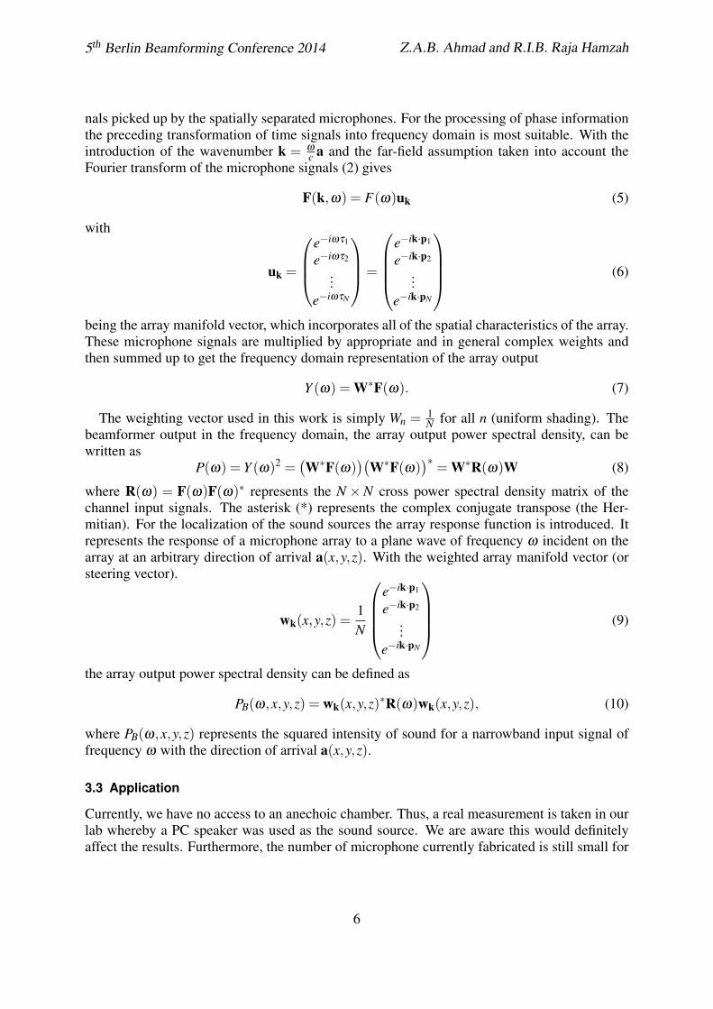
a beamforming array (9 units). However, just for proving the concept, our microphone arraycould localize the speaker as a major noise source as shown in Figure 4. The digital picture takenby the webcam is superimposed with a contour plot of the beamformer algorithm’s output.
Figure 4: Acoustic imaging of sound source using the beam forming array.
4 CONCLUSIONS
The developed beam forming system is suitable for sound source localization even by using lowcost microphones. The performance of our microphones is also comparable the more expensiveGRAS microphones. The beamforming algorithm has also been made using Matlab platformwhich can be ported into open source software like Octave. However, in our research work,the link between the microphones and the beamforming code is still made using rather costlyNational Instrument DAQ cards. Our next research direction will be on replacing these cardswith cheaper alternatives. There are researchers who use affordable on the shelve PCI soundcard and USB sound card to capture the data from microphones. But, there are still no researchthat proves these sound cards can be use for the scale of a beam forming array system whichrequires a lot of sound source input. Another alternative worth exploring would be on usingopen source electronics such as Arduino board as the DAQ card. Apart from the hardwaredevelopment, improvement on our beamforming algorithm and the considerations for near fieldlocalization and multiple sound source would be our next goals.
The developed beamforming system proves that third world universities does not need to beleft behind even if they can not afford high cost equipment. We need to always bear in mind
7
5th Berlin Beamforming Conference 2014 Z.A.B. Ahmad and R.I.B. Raja Hamzah
that some of these equipment can be made ourselves with the fraction of the cost. In this age,through internet and curiosity, one may find ideas that could open up for new possibilities.
ACKNOWLEDGMENT
Financial support of this work by Malaysian Ministry of Education and Universiti TeknologiMalaysia (FRGS grant, vote no. PY/2012/00526) is gratefully acknowledged.
REFERENCES
[1] G. Bennett, J. Mahon, S. Hunt, and C. Harris. “Design of an electret based measurementmicrophone.”, 2003.
[2] G. Bischof. “Acoustic imaging of sound sources – a junior year student research project.”In 38th ASEE/IEEE Frontiers in Education Conference. 2008.
[3] R. Elliot. “Project 134 - 4mA current loop microphone system.” http://sound.westhost.com/project134.htm, 2011.
[4] W. Fonseca and S. Gerges. “Development of a low cost system for pass-by noise beam-forming measurements.” Proceedings of 20th International Congress on Acoustics, 2010.
[5] X. Huang, L. Bai, I. Vinogradov, and E. Peers. “Adaptive beamforming for array signal pro-cessing in aeroacoustic measurements.” Journal of Acoustical Society of America, 131(3),2152–2161, 2012. doi:10.1121/1.3682041.
[6] W. Humphreys Jr., C. Gerhold, G. Zuckerwar, A.J. Herring, and S. Bartram. “Perfor-mance analysis of a cost-effective electret condenser microphone directional array.” 9thAIAA/CEAS Aeroacoustics Conference & Exhibit, 2003. AIAA 2003-3195.
[7] D. Johnson and D. Dudgeon. Array signal processing: concept and techniques. PrenticeHall, Englewood Cliffs, 1993.