30
Raines, Melton & Carella, Inc. Consulting Engineers/Project Managers Zone 7 Water Agency Wastewater Treatment Options for the Buena Vista Area May 2002

Raines, Melton & Carella, Inc.
Consulting Engineers/Project Managers
Zone 7 Water Agency
Wastewater Treatment Optionsfor the Buena Vista Area
May 2002

Wastewater Treatment Options
for the Buena Vista Avenue Area
May 2002
Prepared for the Zone 7 Water Agency
Prepared by Raines, Melton & Carella, Inc.
3650 Mt. Diablo Boulevard, Suite 200 Lafayette, CA 94549

Wastewater Treatment Options for the
Buena Vista Area January 2002
Table of Contents
EXECUTIVE SUMMARY ..................................................................................................1 INTRODUCTION...............................................................................................................1 STUDY AREA...................................................................................................................2 ESTIMATE OF FLOWS AND LOADINGS .......................................................................3
Future Wastewater Treatment Flows ............................................................................5 Wastewater Influent Quality...........................................................................................6
OPTION 1: COMMUNITY WASTEWATER SYSTEM ......................................................6 Collection System Options ............................................................................................7 Community Treatment Plant........................................................................................12 Disposal System..........................................................................................................14 Summary of Community Treatment System Costs .....................................................15 Permitting and Institutional Issues...............................................................................15
OPTION 2: LIVERMORE MUNICIPAL SYSTEM ..........................................................17 Description of Facilities................................................................................................18 LWRC Estimated Costs...............................................................................................18
OPTION 3: IMPROVED ON-SITE TREATMENT ..........................................................19 Estimated Costs ..........................................................................................................20
COMPARISON OF ALTERNATIVES.............................................................................22 Nitrate Removal Costs.................................................................................................22 Effects on Nitrate Mass Balance .................................................................................23 Institutional Issues.......................................................................................................24
CONCLUSION................................................................................................................24 Figures Figure 1 Location of High Nitrate Plume ..........................................................................1 Figure 2 Study Area .........................................................................................................2 Figure 3 Location of Wastewater Sources within Study Area ..........................................3 Figure 4 Conceptual Layout of Community Treatment System .......................................6 Figure 5 Gravity/Force Main Schematic (Option 1)..........................................................8 Figure 6 STEP/STEG Collection System Schematic (Option 2) ......................................9 Figure 7 Gravity Collection System Schematic (Option 3) .............................................11 Figure 8 Community Treatment Plant Process Schematic ............................................13 Figure 9 Steps in Implementing a Community Treatment System..................................16 Figure 10 Implementation of the LWRC Option .............................................................18 Figure 11 On-site Treatment System............................................................................20 Figure 12 Treatment Option Decision Tree....................................................................24 Tables Table 1 Estimated Residential Wastewater Flows ............................................................3 Table 2 Estimated Commercial Wastewater Flows..........................................................4 Table 3 Summary of Wastewater Flows and Nitrate Loading ..........................................4 Table 4 Winery Process Waste........................................................................................5
Wastewater Treatment Options for the
Buena Vista Area January 2002
Table of Contents
Table 5 New Development allowed in the Specific Plan ..................................................5 Table 6 Typical Municipal Wastewater Concentrations ...................................................6 Table 7 Cost Estimate for Collection System Option 1: Gravity/Force Main with
WWTP at Mines/Tesla Rd..........................................................................................8 Table 8 Cost Estimate for Collection System Option 2: STEP/STEG System with
WWTP at Mines/Tesla Rd........................................................................................10 Table 9 Cost Estimate for Collection System Option 3: Conventional System with
WWTP near Buena Vista/East Avenue....................................................................11 Table 10 Community Treatment Plant Performance......................................................13 Table 11 Summary of Treatment Plant Capital Costs.....................................................14 Table 12 Estimated Annual Operating Costs for Community Treatment Plant ...............14 Table 13 Summary of Disposal System Costs...............................................................15 Table 14 Summary of Community Treatment System Costs ..........................................15 Table 15 Summary of Costs for Connection to the LWRC..............................................19 Table 16 Estimated Capital Costs per Customer for On-site Treatment System...........21 Table 17 Total Estimated Capital Costs for On-Site Treatment .....................................21 Table 18 Estimated Annual Operational Costs per Customer for On-site Treatment ....22 Table 19 Total Estimated Annual Costs for On-site Treatment......................................22 Table 20 Comparative Cost per Pound Of Nitrate Removed .........................................23 Table 21 Nitrogen Mass Balance Calculations ..............................................................23

EXECUTIVE SUMMARY A plume of high nitrate concentration has been detected in the main groundwater basin underlying the City of Livermore for many decades. The nitrate concentration in the groundwater exceeds State and Federal Safe Drinking Water limits. Based on the direction of flow within the groundwater basin, the plume appears to begin in the vicinity of the Buena Vista Avenue/Tesla Road area. An evaluation of nitrate sources for the Buena Vista/Tesla Road area indicated that leachate from residential septic tanks in the area was one of the primary sources of nitrate loading to the groundwater basin (Groundwater Nitrate Sources in the Buena Vista Area, May 2002, RMC).
Residential septic tank leachate contributes over 3,200 lb/year, or approximately 40 percent, of the excess nitrate entering the groundwater in the study area. One of the nitrate reduction alternatives discussed in the nitrate sources report was eliminating the septic tanks and replacing them with sewered connections to a wastewater treatment plant. This report evaluates wastewater treatment options for the Buena Vista/Tesla Road study area, which consists of a residential area in the southern portion of Almond Avenue and along Buena Vista Avenue from East Avenue to Tesla Road, and commercial areas near the intersection of Buena Vista Avenue and Tesla Road. The study area is outside of the City of Livermore’s Urban Growth Boundary (UGB) limits and is currently served by septic tanks. Three options were evaluated for removing or reducing the septic tank leachate within the study area: Option 1: Replacing the residential and commercial septic tanks with sewered
connections to a new community wastewater treatment plant Option 2 Replacing the residential septic tanks with sewered connections to the
municipal Livermore Water Reclamation Center Option 3 Upgrading the septic tanks with individual on-site nitrogen reduction
treatment systems The following table summarizes the estimated capital costs, annual operating costs, annual cost per pound of nitrate removed, and the net effect on the nitrogen balance within the study area.
Table ES-1 Comparison of Treatment Options Option 1:
Community Treatment Plant
Option 2: Connection to
LWRC
Option 3: On-Site Enhanced
Treatment Total Capital Cost $1,945,000 $1,169,000 $1,406,000
Annualized Capital Cost $184,000 $110,700 $133,000 Annual Operational Costs $91,000 $39,000 $157,000 Total Annual Cost $275,000 $149,700 $290,000
Nitrates removed, lb/year 3,270 2,850 2,285 Cost per pound of Nitrates Removed $84 $52 $126
Nitrate Loading Reduction 42% 37% 29%

Wastewater Treatment Options for the Buena Vista Area - DRAFT January 2002 Page ES-2 Both of the first two options face significant implementation issues. Option 1 would require development of an institutional framework to fund, design, permit, construct and operate a community collection and treatment system. Option 2 would require revision of the City of Livermore’s UGB to allow sewer service to the area. Option 3 would have the fewest implementation issues since it would maintain the existing system of individual on-site treatment and would not require revisions to the UGB. It would, however, put the burden of operating and maintaining the on-site treatment systems on the homeowner. Based on cost and implementation issues, if it is determined that septic tank leachate should be controlled within the study area, the recommended option is Option 2, revision of the Urban Growth Boundary to include the rural residences along Buena Vista and Almond Avenues, and to convey the wastewater to the existing Livermore Water Reclamation Center. If this is not possible, Option 1 would result in the greatest reduction in nitrates, provided the significant institutional implementation issues could be resolved. However, Option 3 would be easier to implement and would have comparable reduction in nitrate concentration to Option 2.
Figure ES-1 Treatment Option Decision Tree
Yes Implement Option 2Yes Implement Option 2
Eliminate or Reduce Septic
Tank Leachate?
No Project
Yes
No
Can UGB be Revised?
No
Implement Option 1 or 3 depending on resolution of
institutional issues
Eliminate or Reduce Septic
Tank Leachate?
No Project
Yes
No
Can UGB be Revised?
No
Implement Option 1 or 3 depending on resolution of
institutional issues
.

INTRODUCTION The Zone 7 Water Agency (Zone 7) is the wholesale water supplier for Livermore Valley. As part of their ongoing groundwater monitoring efforts, they have noted a persistent plume of high nitrates in the main groundwater basin underlying the City of Livermore. The nitrate concentration ranges from 35 mg/l up to 70 mg/l and exceeds State and Federal safe drinking water standards for nitrates. Figure 1 shows the approximate location of the high nitrate plume.
Figure 1 Location of High Nitrate Plume
In Mary 2Nitrate SReport, aconcludewas one This repoleachateOption 1
Option 2
Option 3
002, Raines, Melton & Carella, Inc. prepared a report entitled Groundwater ources in the Buena Vista Area (Nitrate Sources Report). The Nitrate Sources long with other past evaluations of nitrate sources performed by Zone 7, d that leachate from septic tanks in the Buena Vista Avenue/Tesla Road area of the major sources of excess nitrate loading to the groundwater. rt evaluates alternatives for reducing the nitrate loading from the septic tank
from the Buena Vista Area. The following three options are evaluated: : Replacing the residential and commercial septic tanks with sewered
connections to a new community wastewater treatment plant Replacing the residential septic tanks with sewered connections to the
municipal Livermore Water Reclamation Center Upgrading the septic tanks with individual on-site nitrogen reduction
treatment systems

Wastewater Treatment Options for the Buena Vista Area - DRAFT January 2002 Page 2
STUDY AREA The study area is south of, but adjacent to, the City of Livermore. It is centered around the intersection of Buena Vista Avenue and Tesla Road as shown on Figure 2.
Figure 2 Study Area
The study area isrelatively stable sstudy area and mhomes are alonghomes are immeThere are also 5
• Wente Esta• Tamas Esta• Murietta’s W• Concannon• Stony Ridge
A sixth winery, Rgenerates a relaof the collection development of asmaller wineries,around Wente. Figure 3 shows t
a mix of rural homes and wineries/vineyards. This land use has been ince the 1950’s. There are approximately 100 rural residences in the ost of the homes were built in the 1940’s and 1950’s. Most of the
Buena Vista Avenue between East Avenue and Tesla Road. The other diately adjacent to the City limits on Almond Avenue and East Avenue. wineries as follows:
tes tes ell
etzlaff, is located at the western boundary of the study area. Since it tively low volume of wastewater, and would require a 2,000 ft extension system to serve it, it has not been included in the study area or lternatives. Wente Estates Winery crushes grapes for several of the so most of the wine production activities in the study area are centered
he location of the rural homes and the wineries.

Wastewater Treatment Options for the Buena Vista Area - DRAFT January 2002 Page 3 Figure 3 Location of Wastewater Sources within Study Area
The study area is outside the City of Livermore’s Urban Growth Boundary (UGB) and is therefore not served by the municipal wastewater collection and treatment system. Wastewater from the residences along Buena Vista Avenue is treated by individual on-site septic tanks and leach fields, as is the domestic wastewater from employees, residents and visitors at the wineries. The wineries also generate process waste consisting of grape skins and stems and bottle washing water, which is spread on the vineyards for disposal.
ESTIMATE OF FLOWS AND LOADINGS The study area lies in an unincorporated area of Alameda County and is subject to County ordinances for wastewater treatment. The County has developed a draft Ordinance that regulates wastewater disposal and establishes the wastewater flows to be used for design of treatment facilities for residences and commercial establishments. These design flows were used in calculating the total wastewater flow generated in the study area. The resulting residential design flows are shown in Table 1. Table 1 Estimated Residential Wastewater Flows
Estimated Residential Flow Number of Residences 100 Number of Bedrooms per Residence (1) 3

Wastewater Treatment Options for the Buena Vista Area - DRAFT January 2002 Page 4 Peak Flow per Bedroom 150 Total Peak Flow, gallons/day 45,000 Average Flow, gallons/day (2) 26,000
(1) Assumed number of bedrooms. (2) Average flow assumed to be 60% of peak flow. In addition, each of the commercial facilities was contacted to determine the average and peak numbers of employees, residents, and visitors. The estimated wastewater flows were calculated using this information plus the design values listed in the draft Ordinance. The resulting commercial wastewater flows are shown on Table 2.
Table 2 Estimated Commercial Wastewater Flows
Sanitary Waste Avg Peak Avg Peak Avg Peak Avg Peak Avg PeakStony Ridgea. Wineries Wente Tamas Estates Murietta's Well Concannon
No. of Residents 0 2 0 0 3 6 0 0gpcd (1) 100 150 100 150 100 150 100 150Residential Flow, gpd 0 300 0 0 300 900 0 0
No. employees 80 100 4 5 1 2 15 18gpcd (1) 15 15 15 15 15 15 15 15Employee Flow, gpd 1,200 1,500 60 75 15 30 225 270
No. visitors 200 300 15 120 100 200 50 400gpcd (1) 2.5 2.5 2.5 2.5 2.5 2.5 2.5 2.5Visitors Flow, gpd 500 750 37.5 300 250 500 125 1000
Subtotal, gpd 1,700 2,600 100 400 600 1,400 400 1,300 1,000 3,300
Avg PeakTotal Winery Sanitary Flow, gpd 3,900 9,000
Questa EngineeringFebruary 2000
Flow estimates from"Design Report for
Stony Ridge Winery"
The estimated nitrogen concentration from the septic tank leachate is assumed to be 35 mg/l, which is an average residential concentration. The total annual nitrate loading can be calculated using the following formula:
(Average Flow, gallons/day)*(365 day/yr)*(35 mg/l)*(8.34x10-6, a conversion factor to lb/yr)
The resulting residential and commercial flow and nitrate loading are shown in Table 3.
Table 3 Summary of Wastewater Flows and Nitrate Loading
Component Average Flow, gpd Peak Flow, gpd Annual Nitrate Load, lb/yr
Residential Septic Tanks 26,000 36,000 2,850 Commercial Septic Tanks 3,900 9,000 420 Total 30,000 45,600 3,270 These estimates of wastewater flow do not include the process waste generated by the wineries during the grape crushing season. The process waste is a high volume, short duration flow. Sizing a community treatment plant to handle the process waste would greatly increase the required capacity, and therefore cost, of a plant. The extra capacity would be idle during all but the crushing season. It is therefore assumed for this

Wastewater Treatment Options for the Buena Vista Area - DRAFT January 2002 Page 5 evaluation that the process waste would continue to be handled as it is now, i.e. spread on the vineyard land. Table 4 is an estimate of the process flow from the wineries, using the Alameda County draft Ordinance unit values along with production data provided by the wineries.
Table 4 Winery Process Waste
Wente Tamas Estates Murietta's Well Concannon Stony RidgeProcess Waste
Wineries
FTL2atiT
T
S
S
S
Uiasta
No. of cases per year (1) 450,000 0 0 75,000 33Gal wine per case (2) 2.4 2.4 2.4 2.4 2.4Gal wine produced 1,080,000 0 0 180,000 79Length of crush, days (1) 60 0 0 60 60
Peak Daily Flow, (gal of wine x 2) / No. of days of crush (2) 36,000 6,000 3
Total Peak Process Flow, gpd 42,000
(1) Production information provided by wineries(2) Unit values established by Alameda County Ordinance
Wente provides grape processing for T.E. and M.W wineries
for up to 60 days per year
uture Wastewater Treatment Flows he area surrounding the study area is primarily agricultural land. However, the City of ivermore has prepared a report entitled South Livermore Valley Specific Plan, February 001, that provides the framework for future growth and development within an 1,891-cre unincorporated area along the city’s southern boundary. The Specific Plan divides he unincorporated area into seven subareas. The study area is adjacent to, but not ncluded in two of the subareas, Subarea #2 and Subarea #3. he Specific Plan calls for the following development in these two Subareas:
able 5 New Development allowed in the Specific Plan
ubarea Residential Development
Commercial Development
ubarea #2 Up to 574 dwelling units 2 wineries, bed and breakfasts, or restaurants
ubarea #3 Up to 177 dwelling units Small winery or bed and breakfast and a tasting room or restaurant
sing the unit values set forth in the Alameda County draft Ordinance, this could result n an additional wastewater flow of approximately 300,000 gallons per day. This flow is pproximately 10 times larger than a package treatment plant that would be sized to erve the study area. Therefore the community treatment plant alternative developed in his report will not be sized to treat the flows from the future developments in Subareas 2 nd 3.

Wastewater Treatment Options for the Buena Vista Area - DRAFT January 2002 Page 6 Wastewater Influent Quality The concentration of the domestic wastewater is assumed to be typical residential wastewater. The quality of the influent wastewater to the treatment plant is assumed to be the following:
Table 6 Typical Municipal Wastewater Concentrations
Constituent Concentration mg/l BOD 200 Total Suspended Solids 200 Nitrate 35
OPTION 1: COMMUNITY WASTEWATER SYSTEM The first option considered is to eliminate the commercial and residential septic tanks and replace them with a sewered connection to a community wastewater treatment plant sited within the study area. Implementing a community wastewater treatment system for the study area would require construction of three main components; the collection system, the treatment system, and the disposal system. In discussions with Zone 7, the preferred location for a community treatment plant would be near the intersection of Mines Road and Tesla Road as shown on Figure 4. A new sewer system would be required to collect the wastewater from each individual source and convey it to the treatment plant. The treated water produced by the plant could be used to irrigate adjacent vineyards.
Figure 4 Conceptual Layout of Community Treatment System

Wastewater Treatment Options for the Buena Vista Area - DRAFT January 2002 Page 7 The following sections describe the options for collection, treatment, and disposal facilities of the community wastewater system.
Collection System Options Although the study area is relatively flat, with an average slope of less than 1%, there is an overall drop in elevation of approximately 50 feet across the area from southeast to northwest. The elevation at the northern end of Buena Vista near East Avenue is approximately 560 feet, while the elevation of Wente Brothers winery is approximately 610 feet. The elevation of the proposed location of the community treatment plant near the corner of Mines and Tesla Roads is approximately 600 feet. Ideally, a wastewater treatment plant would be located at the lower end of a collection system so that the wastewater could flow by gravity to the plant. In this case, the treatment plant is near the upper elevation of the collection system, so most of the wastewater would need to be pumped to the plant through pressurized sewers (force mains). Three collection system options have been evaluated:
• Sewer Option 1: Conveying the wastewater to a plant at Mines/Tesla via conventional gravity sewers and force mains
• Sewer Option 2: Conveying the wastewater to a plant at Mines/Tesla via a Septic Tank Effluent Pumping (STEP) type collection system
• Sewer Option 3: Moving the treatment plant to a lower elevation and using conventional gravity sewers
Each collection system option is discussed below.
Sewer Option 1 Gravity and Force Mains with Treatment Plant Located at Corner of Mines and Tesla Road In conventional sewer design, it is generally preferable to transport wastewater to a treatment plant that is down slope, using gravity for as much distance as possible, and minimizing the number of pump stations required to convey the flow. In this case, since the treatment plant is upslope of the residences, using gravity alone would require pipe trenches more than 40 feet deep as they approach the plant site, and a pump station would still be required at the plant to pump the wastewater up to the surface. When the terrain dictates that water in the gravity pipeline must be pumped, a separate force main pipeline is needed to convey the pumped water. Designing a gravity/pumped system such as this requires a balance between gravity flow and force main flow to minimize costs. For this option, six small pump stations and corresponding 6” force main pipelines would be needed to pump wastewater from the residences on Almond and Buena Vista Avenues as well as the winery and the proposed bed and breakfast located along Tesla Rd. west of the plant site. Note that the effluent from Tesla west of Buena Vista is transported to the plant via two separate pump stations. In this case, it was less expensive to install two separate pump stations than to transport the flow via gravity to a shared pump station. Wastewater from establishments along Tesla Rd east of the plant and those along Mines Road can flow by gravity to the plant. Figure 5 illustrates this option.

Wastewater Treatment Options for the Buena Vista Area - DRAFT January 2002 Page 8 Figure 5 Gravity/Force Main Schematic (Option 1)
Tfasp
T
DG
F
L
C
his option would require approximately 10000 ft of 6” gravity pipe, approximately 7,500 t of 6” force main pipe, and 6 small (1hp) pump stations. New lateral connections are lso required from each house or commercial establishment to connect to the gravity ewer. Table 7 shows the estimated cost for this option, excluding the cost of land urchases or easements.
able 7 Cost Estimate for Collection System Option 1: Gravity/Force Main with WWTP at Mines/Tesla Rd
Option 1: Conventional Sewer/WWTP at Buena Vista/Tesla escription Qty Unit Unit Cost Total Cost ravity Pipeline
6" Gravity Sewer along Buena Vista Ave 5280 LF $32 $169,000 6" Gravity Sewer from Almond Ave 1500 LF $32 $48,000 6" Gravity Sewer along Tesla Rd 2400 LF $32 $77,000 6" Gravity Sewer along Mines Rd 1200 LF $32 $38,000 Manholes (every 400 ft) 26 EA $2,000 $52,000 Subtotal Gravity Pipelines $384,000
orce Mains 6" Force Main along Buena Vista 5500 LF $32 $176,000 6" Force Main along Tesla 2000 LF $32 $64,000 Duplex Pump Stations 6 EA $7,000 $42,000 Subtotal Force Mains $282,000
aterals Lateral connections to collection system 100 EA $750 $75,000
ontingency at 25 percent $185,000 Total for Option 1 $930,000

Wastewater Treatment Options for the Buena Vista Area - DRAFT January 2002 Page 9 Sewer Option 2 STEP/STEG System with Treatment Plant Located at Corner of Mines and Tesla Road In the past decade alternate wastewater collection systems have become more accepted and more widely used. One such alternative system, called the Septic Tank Effluent Pump/Septic Tank Effluent Gravity (STEP/STEG) system uses the septic tanks as primary treatment of the wastewater and then delivers this treated water to the treatment plant. In the septic tanks, most of the solids settle to the bottom or float to the top of the tank, so the water that flows through the collection system is less likely to become obstructed in the sewer line. For this reason, smaller diameter pipes can be used. The water is delivered to the treatment plant either via gravity flow (STEG) or force main flow (STEP). The terrain for this study area dictates a STEP system in which a small (1/3 hp) pump is installed downstream of each septic tank to pump the water through the collection system. Figure 6 illustrates the STEP/STEG option.
Figure 6 STEP/STEG Collection System Schematic (Option 2)
One concern with the STEP/STEG system is the effect of rainwater and groundwater intrusion into the sewer system. This phenomenon is called infiltration and inflow (I/I), and in conventional sewers it primarily occurs through cracked pipes, leaky manholes, or improperly connected storm drains. Since STEP/STEG systems use septic systems as part of the collection system, older septic systems can also be significant I/I contributors. Since the STEP/STEG system uses pipes with smaller diameters, it is more sensitive to the effects of wet weather I/I than the conventional system. For this reason, it is frequently recommended that no manholes be installed in the street and that all septic tanks be replaced. Replacing all of the septic tanks in a system can become very expensive, but in most cases of STEP/STEG implementation, it has proven to be necessary. This option would require approximately 4,800 ft of 3” gravity pipe, approximately 9,400 ft of 3” force main pipe, and 100 STEP pumping packages. The gravity conveyance system serving the area east of the plant site along Tesla Road, and the area south of the plant site along Mines Road would be the same as for collection system Option 1. Table 6 shows the estimated cost for this option. If replacement of the existing septic tank is not required, this option is less expensive than the conventional gravity/force

Wastewater Treatment Options for the Buena Vista Area - DRAFT January 2002 Page 10 main alternative of Sewer Option 1. However, if replacement of the existing septic tanks is required, the STEP/STEG system is approximately the same cost as Sewer Option 1.
Table 8 Cost Estimate for Collection System Option 2: STEP/STEG System with WWTP at Mines/Tesla Rd
Option 2: STEP/STEG Sewer/WWTP at Buena Vista/Tesla Description Qty Unit Unit Cost Total Cost Gravity Portion of System
6" Gravity Sewer along Tesla Rd - east 2100 LF $32 $67,000 6" Gravity Sewer from Almond Ave 1500 LF $32 $48,000 6" Gravity Sewer along Mines Rd 1200 LF $32 $38,000 Manholes (every 400 ft) 8 EA $2,000 $16,000 Lateral connections to collection system 3 EA $750 $2,000 Subtotal Gravity Pipelines $171,000
STEP Portion of System 3" Force Main along Buena Vista 5280 LF $28 $148,000 3" Force Main along Almond Avenue 1500 LF $28 $42,000 3" Force Main along Tesla Rd - west 2600 LF $28 $73,000 Subtotal Force Mains $263,000
STEP House connections Dealer provided STEP packages 100 EA $2,000 $200,000 Lateral connections to STEP system 100 EA $200 $20,000 Subtotal House Connections $220,000
Contingency at 25 percent $164,000 Total for Option 2 $820,000
Potential Additional Cost Replace Septic Tanks 100 EA $3,000 $300,000 Total Cost including septic tank replacement $1,120,000
Sewer Option 3: Gravity Sewers with Treatment Plant Located at Corner of Buena Vista and East Avenue One way to minimize the costs of the collection system would be to relocate the treatment plant to a lower elevation so the majority of the wastewater can flow by gravity. This option assumes that the treatment plant would be located at an undetermined location near the corner of Buena Vista and East Avenue. A new gravity sewer would be installed along Buena Vista. The entire collection system would then be gravity, except for the portion on Tesla Road west of Buena Vista. The two establishments in this area would require a force main to pump the wastewater up to the main collection pipeline at the corner of Buena Vista Avenue and Tesla Road. Figure 7 illustrates this option.

Wastewater Treatment Options for the Buena Vista Area - DRAFT January 2002 Page 11
Figure 7 Gravity Collection System Schematic (Option 3)
This option would require approximately 11,000 ft of 6” gravity pipe, approximately 2,000 ft of 6” force main pipe, and 2 small (1hp) pump stations. Table 9 shows the estimated cost for this option.
Table 9 Cost Estimate for Collection System Option 3: Conventional System with WWTP near Buena Vista/East Avenue
Option 3: Gravity Sewer/WWTP near Buena Vista/East Ave. Description Qty Unit Unit Cost Total Cost Gravity Pipeline
6" Gravity Sewer along Buena Vista Ave 5280 LF $32 $169,000 6" Gravity Sewer from Almond Ave 1500 LF $32 $48,000 6" Gravity Sewer along Tesla Rd east of BV 2700 LF $32 $86,000 6" Gravity Sewer along Mines Rd 1200 LF $32 $38,000 Manholes (every 400 ft) 26 EA $2,000 $52,000 Subtotal Gravity Pipelines $393,000
Force Mains 6" Force Main along Tesla Rd west of BV 1750 LF $32 $56,000 Duplex Pump Stations 2 EA $7,000 $14,000 Subtotal Force Mains $70,000
Laterals Lateral connections to collection system 100 EA $750 $75,000
Contingency at 25 percent $135,000 Total for Option 3 $670,000

Wastewater Treatment Options for the Buena Vista Area - DRAFT January 2002 Page 12 Summary of Collection System Options If the treatment plant is located near the corner of Mines Road and Tesla Road, the recommended collection system option is Option 1, a conventional gravity system/force main system. Assuming most of the existing septic tanks would need replacement, the STEP/STEG system is more costly, would require more maintenance due to the large number of small pumps (one at each septic tank), and is more subject to operational problems due to the small size of the STEP force main piping. If the treatment plant could be located at the lower end of the study area, near the corner of Buena Vista and East Avenue, most of the wastewater can then flow by gravity (Sewer Option 3). This option is the least expensive collection system. Since it has the fewest number of pump stations it would also require the least amount of maintenance.
Community Treatment Plant Numerous types of wastewater treatment plants have been developed specifically to serve small developments or non-sewered areas that are not suitable for individual septic tank systems. These small treatment systems are termed “package plants” and are characterized by having a small footprint and minimal operational requirements. The basic processes at all treatment plants, regardless of the size, are to provide biological treatment to treat the wastewater, solids separation to remove the solids from the treated effluent, and disinfection to kill pathogenic organisms in the effluent. An additional requirement for the community treatment system serving this study area would be to remove nitrate from the wastewater effluent. This is done with specialized bacteria that convert ammonia to nitrate and then to nitrogen gas, which is released into the air. Typical package plant systems have included rotating biological contactors, sequencing batch reactors, and standard activated sludge processes, among others. These types of package plants typically have a tank where the biological process takes place followed by a clarifier for solids/liquid separation. The treatment plants can be configured to provide nitrogen removal and, with the addition of tertiary filtration and disinfection, the effluent can be used for non-potable uses such as irrigation. Process Description Although any of these types of plants could be used within the study area, the type of treatment plant used for estimating costs in this report is a submerged membrane bioreactor plant by Zenon Environmental Systems. This type of treatment plant uses microfiltration membranes for solids/liquid separation. The membranes are submerged in the biological process, which also provides nitrification/denitrification for nitrogen removal. The combined process eliminates the need for separate clarifiers and separate tertiary filtration allowing the plant to be built within a smaller footprint since less tankage is required. The effluent is disinfected with ultraviolet light (UV) and the resulting water meets State of California Title 22 requirements for non-potable water reuse. This type of treatment plant is usually built inside a structure that is designed to blend with the surrounding area. For this application, the treatment structure could be designed to look like a winery, barn, or other rural structure. The treatment processes included in this package plant are as follows:

Wastewater Treatment Options for the Buena Vista Area - DRAFT January 2002 Page 13 Treatment Process Description Biological Treatment High rate biological treatment including anoxic zones for
nitrification/denitrification (nitrogen removal) Solids/Liquid Separation Submerged microfilters, which have a 0.1 micron pore size
to remove bacteria and most viruses Tertiary Filtration The submerged microfilters also provide the tertiary filtration
function Disinfection Ultraviolet (UV) light, which deactivates the pathogenic
organisms Solids Dewatering On-site sludge drying bed followed by landfill of the dried
solids Figure 8 is a schematic of a submerged membrane community treatment plant
Figure 8 Community Treatment Plant Process Schematic
Ta
Ta
ble 10 summarizes the treatment process sizing and performance.
ble 10 Community Treatment Plant Performance
Process Performance Effluent Quality
Process Sizing
Size
Average Flow 39,000 gpd Residence Time 15.5 hours
Peak Flow 2,400 gph Required Bioreactor Volume 24,500 gal
BOD5 < 5 mg/l Number of Bioreactor Tanks 1
Total Suspended Solids < 5 mg/l Length of Bioreactor Tanks 50 ft
Ammonia < 0.5 mg/l Width of Bioreactor Tanks 12 ft
Total Nitrogen < 8 mg/l Height of Bioreactor Tanks 12 ft
Total Coliforms < 2.2 MPN/100 ml Sludge production 265 gpd
Sludge wasting interval 5 weeks
InfluentWastewater
Air Sludge to DryingBed
Bioreactor
UVDisinfection
Treated Waterfor
Irrigation

Wastewater Treatment Options for the Buena Vista Area - DRAFT January 2002 Page 14 Community Treatment Plant Capital Costs The system proposed by ZENON for this project would be a single train system with complete mechanical redundancy. The complete wastewater treatment system is containerized and consists of epoxy painted carbon steel bioreactor tanks and skids for the associated process equipment. The treatment plant is housed a building, which could be configured to blend with the surrounding area. Table 11 summarizes the estimated costs for the treatment plant.
Table 11 Summary of Treatment Plant Capital Costs Description Qty Unit Unit Cost Total Cost Package Plant
Process Equipment 1 LS $390,000 $390,000 Concrete Tanks 75 CY $500 $38,000 Solids Drying Bed 1 LS $100,000 $100,000 Pre-engineered Building 3500 SF $100 $350,000 Misc. piping, electrical, sitework $66,000 Contingency at 25 percent $236,000 Total $1,180,000
Treatment Plant Operational Costs In addition to the initial capital costs, operation of the treatment plant would be an on-going, expense. Table 12 summarizes the estimated annual operating costs for the community treatment plant.
Table 12 Estimated Annual Operating Costs for Community Treatment Plant Description Qty Unit Unit Cost Total Cost Blower and pump operation 127,000 kw-hr $0.15 $19,050 UV disinfection 5,000 kw-hr $0.15 $750 Sludge hauling and disposal 1 LS $30,000 $30,000 Effluent Pump Operation, 3 hP 9,800 kw-hr $0.15 $1,470 Operator's Labor
Emergency Service, 4 hr month 50 hours/year $60 $3,000 Routine Service, 8-9 hr/wk 450 hours/year $60 $27,000 Yearly Service, 4 days/year 32 hours/year $60 $1,920
Parts & Repair 1 LS $3,600 $3,600 Membrane Replacement 1 LS $3,500 $3,500 Sodium Hydroxide 1 LS $1,000 $1,000
Total Operational Costs $91,000
Disposal System The water produced from the community treatment plant would meet the strictest requirements that the State of California has established for recycled water. It is assumed for estimating costs that the treated water would be used for irrigation of adjacent vineyards, although implementing this would require development of User Agreements with the owners of the adjacent properties. The volume of water produced

Wastewater Treatment Options for the Buena Vista Area - DRAFT January 2002 Page 15 from the community treatment plant would be adequate for irrigation of approximately 40 acres. The facilities required to use the water for irrigation include distribution pumping and piping to the vineyards. The estimated capital costs for the disposal system are shown in Table 13.
Table 13 Summary of Disposal System Costs Description Qty Unit Unit Cost Total Cost Piping, 4" PVC 3000 LF $20 $60,000
Pump Station 1 LS $10,000 $8,000
Misc. piping, electrical, sitework $6,800
Contingency at 25 percent 18,000
Total $95,000
Summary of Community Treatment System Costs The package treatment plant could be located either near the corner of Mines Road and Tesla Road combined with the gravity/force main system, or could be located near the corner of Buena Vista and East Avenue combined with the gravity collection system option. The resulting capital costs are as shown in Table 14.
Table 14 Summary of Community Treatment System Costs
Cost
Treatment Plant at Mines/Tesla with Gravity/Force Main
Sewers
Treatment Plant at Buena Vista/East Avenue with Gravity
Sewers Sewer System $930,000 $670,000 Treatment Plant $1,180,000 $1,180,000 Disposal System $95,000 $95,000 Total Capital Cost $2,205,000 $1,945,000
Annual Operating Costs $91,000 $91,000
Permitting and Institutional Issues Constructing a new community treatment system is a complicated endeavor and would require developing an institutional structure to implement the permitting, design, construction, and on-going operation of the system. There are a number of implementation steps that would be needed. They are summarized as follows:
Obtain Permitting Environmental Impact Report - required by the California Environmental Quality Act to determine if there are significant environmental impacts associated with construction of the system and, if so, whether those impacts can be mitigated.

Wastewater Treatment Options for the Buena Vista Area - DRAFT January 2002 Page 16 Waste Discharge Permit - required for construction and operation of a wastewater treatment plant. It is issued by the San Francisco Bay Regional Water Quality Control Board. Title 22 Permit - required for construction and operation of a recycled water system. It is issued by the Regional Water Quality Control Board after review by the Department of Health Services Air Permit - required to regulate the air emissions from construction and operation of a wastewater treatment plant. It is issued by the Bay Area air Quality Management District after review of any potential air emissions Construction Permits: - as required by Alameda County for construction
Obtain Funding Funding would be required not only for the initial capital costs, but also for on-going operation and maintenance of the system, for preparation of annual reports and permit renewal, and for establishment of a reserve fund for capital equipment replacement. Funding may include sources such as property assessments, sales of bonds, and user fees.
Develop Institutional Structure Implementation of a community system would require an institutional structure to designate an entity to develop and hold the permits and to oversee the funding, design, construction, and operation of the system. A representative of the Regional Water Quality Control Board has indicated that the Board would strongly recommend utilizing the existing Livermore facilities to treat wastewater. If this is not possible, the Board urges utilizing an existing governmental agency such as the County of Alameda or Zone 7 Water Agency to operate, manage and be responsible for the wastewater treatment and effluent discharges. An assessment district or homeowner’s association may also be needed to manage the funding for the system.
Design and Construction The design and construction of the facilities would require land acquisition for the treatment plant site, easements for construction of the collection system and pump stations, consultants or equipment vendors for development of plans and specifications and contractors for the actual construction. During the design and construction phases there would be need for extensive interaction with the homeowners for installation of sewer laterals, and coordination with the owner of the vineyard where the recycled water would be applied.
On-going Operation There would be on-going requirements for operation and maintenance of the collection, treatment, and disposal systems. In addition, the RWQCB requires an annual report on the treatment and disposal system, as well as periodic renewals of the operating permits. Figure 9 is a flow chart summarizing the implementation process.
Figure 9 Steps in Implementing a Community Treatment System

Wastewater Treatment Options for the Buena Vista Area - DRAFT January 2002 Page 17
PermittingPermitting Design and ConstructionPermittingPermitting Design and Construction
OPTheporpersectreacapAntheboucurInfoscesep
hEIR
hWaste Discharge Permit
hTitle 22 Permit
hAir Permit
hCounty ConstructionPermits
Funding
hAssessments
hBonds
hUser Fees
Institutional
hHomeowner’sAssociation
hMemorandum of Understanding
hUser Agreements forRecycled Water
hJoint Powers Association
hEIR
hWaste Discharge Permit
hTitle 22 Permit
hAir Permit
hCounty ConstructionPermits
Funding
hAssessments
hBonds
hUser Fees
Institutional
hHomeowner’sAssociation
hMemorandum of Understanding
hUser Agreements forRecycled Water
hJoint Powers Association
hLand Acquisition
hEasements
hPredesign
hDesign of:
–House Laterals
–Collection System
–Treatment Plant
–Disposal System
hConstruction of:
–House Laterals
–Collection System
–Treatment Plant
–Disposal System
Design and Construction
hLand Acquisition
hEasements
hPredesign
hDesign of:
–House Laterals
–Collection System
–Treatment Plant
–Disposal System
hConstruction of:
–House Laterals
–Collection System
–Treatment Plant
–Disposal System
On-going Operation
hCollection System
hTreatment Plant
hDisposal System
hAnnual Permit Reports
hPermit Renewals
hO&M Funding
hFacility Maintenance
h Equipment Replacement
On-going Operation
hCollection System
hTreatment Plant
hDisposal System
hAnnual Permit Reports
hPermit Renewals
hO&M Funding
hFacility Maintenance
h Equipment Replacement
hEIR
hWaste Discharge Permit
hTitle 22 Permit
hAir Permit
hCounty ConstructionPermits
Funding
hAssessments
hBonds
hUser Fees
Institutional
hHomeowner’sAssociation
hMemorandum of Understanding
hUser Agreements forRecycled Water
hJoint Powers Association
hEIR
hWaste Discharge Permit
hTitle 22 Permit
hAir Permit
hCounty ConstructionPermits
Funding
hAssessments
hBonds
hUser Fees
Institutional
hHomeowner’sAssociation
hMemorandum of Understanding
hUser Agreements forRecycled Water
hJoint Powers Association
hLand Acquisition
hEasements
hPredesign
hDesign of:
–House Laterals
–Collection System
–Treatment Plant
–Disposal System
hConstruction of:
–House Laterals
–Collection System
–Treatment Plant
–Disposal System
Design and Construction
hLand Acquisition
hEasements
hPredesign
hDesign of:
–House Laterals
–Collection System
–Treatment Plant
–Disposal System
hConstruction of:
–House Laterals
–Collection System
–Treatment Plant
–Disposal System
On-going Operation
hCollection System
hTreatment Plant
hDisposal System
hAnnual Permit Reports
hPermit Renewals
hO&M Funding
hFacility Maintenance
h Equipment Replacement
On-going Operation
hCollection System
hTreatment Plant
hDisposal System
hAnnual Permit Reports
hPermit Renewals
hO&M Funding
hFacility Maintenance
h Equipment Replacement
TION 2: LIVERMORE MUNICIPAL SYSTEM City of Livermore boundaries are adjacent to the northern, eastern, and western tions of the study area. Wastewater from Livermore is treated at the 5 million gallon day Livermore Water Reclamation Center (LWRC). In addition to primary, ondary, and tertiary treatment processes common to most modern wastewater tment facilities, LWRC includes microfiltration and reverse osmosis processes able of filtering out impurities as minute as bacteria, viruses and dissolved chemicals.
alternative to constructing a community treatment system is to connect the area to existing LWRC. However, the study area lies outside Livermore’s urban growth ndaries designated in the South Livermore Specific Plan and therefore cannot
rently be served by the LWRC. rmation from the City of Livermore Planning Department indicates there are three narios by which the Buena Vista Avenue area could be served by sewers rather than tic tanks: 1. The City could extend the sewer down Buena Vista Ave without annexation as
long as it is a) contiguous with the City limits, b) for only residential connections as long as they were for 10 or fewer existing parcels and c) only if the residents sign a binding agreement that they would not subdivide their parcels or conduct non-residential (e.g., commercial) activities on them. The Buena Vista area meets the requirement for being contiguous with the City, but since there are more than 10 parcels involved, this scenario would not apply.

Wastewater Treatment Options for the Buena Vista Area - DRAFT January 2002 Page 18
2. For greater than 10 residential connections, unanimous approval would be required by all LAVWMA agencies in addition to the binding agreements above regarding not subdividing their parcels and not conducting commercial activities.
3. The City could annex Buena Vista Avenue, thereby eliminating the LAVWMA approval requirement. However, to annex Buena Vista Ave and move the Urban Growth Boundary, the City would have to obtain voter approval. Approval of the Pleasanton City Council and Alameda County may also be required since they were both signers of the South Livermore Plan, which precluded the growth-inducing services beyond the UGB.
Description of Facilities In this option, the City of Livermore would construct a collection system to serve the residences on Almond, East, and Buena Vista Avenues. The wineries and proposed B&B along Tesla Road would remain on septic tanks since revisions to the Urban Growth Boundary would preclude service to commercial facilities. The collection system for the rural residences would be similar to the gravity collection system option described previously as Sewer Option 3. However, instead of connecting to a community treatment plant near East Avenue, it would instead connect to the existing municipal collection system located in East Avenue. The City of Livermore would manage the design and construction of the collection system. The wastewater would be conveyed to the LWRC, which is operated and maintained by City staff. Figure 10 illustrates the implementation steps required for this option.
Figure 10 Implementation of the LWRC Option
PermittingPermitting Design and Construction Design and Construction PermittingPermitting Design and Construction Design and Construction
hCounty ConstructionPermits
Funding
hUser Fees
Institutional
hModify Urban GrowthLimits Boundary throughAction by LAVWMAand/or Action by Councilwith voter approval
hCounty ConstructionPermits
Funding
hUser Fees
Institutional
hModify Urban GrowthLimits Boundary throughAction by LAVWMAand/or Action by Councilwith voter approval
by City of Livermore
hEasements
hDesign of:
–House Laterals
–Collection System
hConstruction of:
–House Laterals
–Collection System
by City of Livermore
hEasements
hDesign of:
–House Laterals
–Collection System
hConstruction of:
–House Laterals
–Collection System
On-going Operation by City of Livermore at
LWRC
On-going Operation by City of Livermore at
LWRC
hCounty ConstructionPermits
Funding
hUser Fees
Institutional
hModify Urban GrowthLimits Boundary throughAction by LAVWMAand/or Action by Councilwith voter approval
hCounty ConstructionPermits
Funding
hUser Fees
Institutional
hModify Urban GrowthLimits Boundary throughAction by LAVWMAand/or Action by Councilwith voter approval
by City of Livermore
hEasements
hDesign of:
–House Laterals
–Collection System
hConstruction of:
–House Laterals
–Collection System
by City of Livermore
hEasements
hDesign of:
–House Laterals
–Collection System
hConstruction of:
–House Laterals
–Collection System
On-going Operation by City of Livermore at
LWRC
On-going Operation by City of Livermore at
LWRC
LWRC Estimated Costs Staff at the LWRC indicates that the sewer connection fee for a single family residence would be $9,353. This cost includes the lateral connection from the house, installation of a new sewer system, and treatment capacity at the LWRC. In addition to the connection fee, there is a monthly sewer bill to pay for the ongoing operation costs of operating and maintaining the LWRC system. The current monthly sewer bill for a single family

Wastewater Treatment Options for the Buena Vista Area - DRAFT January 2002 Page 19 residence is $32.60. The resulting estimated costs for connection to the LWRC would be as shown on Table 15.
Table 15 Summary of Costs for Connection to the LWRC Description Qty Unit Unit Cost Total Cost Capital Cost Connection to the LWRC 100 EA 9353 $935,000
Contingency at 25 percent $234,000
Total estimated cost $1,169,000 Annual Operating Cost Annual SFR sewer bill 100 EA $390 $39,000
OPTION 3: IMPROVED ON-SITE TREATMENT This treatment alternative would maintain the individual private septic tank and leach field systems currently in place in the study area, but would add an additional treatment step to remove nitrogen and improve the overall water quality of the effluent. Representative of this type of advanced septic treatment is the FAST™ (fixed activated sludge treatment) system, which is a submerged filter unit installed below ground in a configuration similar to that of a standard septic tank. Wastewater enters the primary settling zone of the tank where primary solids are removed. Flow is then recirculated through the FAST™ filter at the effluent end of the tank where microorganisms attached to the filter media provide more advanced nitrogen and organic removal. A small portion of the recirculated wastewater flow is periodically discharged to a leaching field. An enclosed, above-ground blower supplies air to the system to support bacterial growth the filter media. As with a septic tank, solids must be periodically pumped out and trucked away for disposal. For existing households, the FAST™ system can be installed in the second compartment of an existing septic tank if the tanks is in good repair. Otherwise, it is installed in a separate septic tank downstream from the existing tank. The treatment system itself does not have a significant land requirement since the only above-grade equipment is the blower. However, as with any septic tank system, significant land must be reserved for the leaching fields used for disposal of the effluent. A schematic of an on-site treatment system is shown in Figure 11.

Wastewater Treatment Options for the Buena Vista Area - DRAFT January 2002 Page 20
Figure 11 On-site Treatment System
Settling Zone
Treatment Zone
To Leach Field
Blower
From Individual Customer Settling
Zone
Treatment Zone
To Leach Field
Blower
Settling Zone
Treatment Zone
To Leach Field
Blower
From Individual Customer
The manufacturers of the FAST™ process state that the FAST™ system achieves 70% denitrification. Assuming an influent total nitrogen concentration of 30 mg/l, the expected effluent total nitrogen concentration would be approximately 9 mg/l. The advantages of on-site treatment using a FAST™ -type system include:
• Can be retrofitted into existing individual septic tanks and leach fields if they are in good repair
• Eliminates need for sewer construction Septage pumping requirements are similar to a standard septic system
• Provides greater level of treatment than existing septic tank effluent and removes up to 70% of nitrogen
• Easier to permit since present system of private sewage disposal system is maintained and eliminates need to revise Urban Growth Boundary
The disadvantages of on-site treatment include:
• Effluent quality is not as good as a package plant
• More maintenance is required by individual households to maintain on-site blowers and replace air filters
• Significant area is required for leach fields for larger commercial developments
• Effluent is discharged to leach fields and is not suitable for reuse for irrigation or other non-potable purposes
Estimated Costs The estimated capital costs for retrofitting existing septic tank customers is shown in Table 16 for three conditions; residential customers, small wineries, and medium wineries

Wastewater Treatment Options for the Buena Vista Area - DRAFT January 2002 Page 21 Table 16 Estimated Capital Costs per Customer for On-site Treatment System
Qty Unit Unit Cost Total Cost Capital Cost per Residence Septic Tank 1 EA $3,000 $3,000 FAST System 1 EA $3,000 $3,000 Connections, Electrical, Misc. 1 LS $1,000 $1,000 Contingency at 25 percent $2,000
Total per residence $9,000
Capital Cost per Small Winery Grease Interceptor 1 EA $8,000 $8,000 Septic Tank 1 EA $8,000 $8,000 FAST vaults 2 EA $8,000 $16,000 FAST 3.0 treatment system 2 EA $13,000 $26,000 Effluent pump station
Vault 1 EA $8,000 $8,000 Duplex pump system 1 EA $2,000 $2,000
Misc. piping, electrical, sitework at 10 percent $6,800 Contingency at 25 percent $18,700
Total per small winery $93,500
Capital Cost per Medium Winery Grease Interceptor 2 EA $8,000 $16,000 Septic Tank 2 EA $8,000 $16,000 FAST vaults 2 EA $8,000 $16,000 FAST 4.0 treatment system 2 EA $19,000 $38,000 Effluent pump station
Vault 1 EA $8,000 $8,000 Duplex pump system 1 EA $2,000 $2,000
Misc. piping, electrical, sitework at 10 percent $9,600 Contingency at 25 percent $26,400
Total per medium winery $132,000 The total capital costs are as follows.
Table 17 Total Estimated Capital Costs for On-Site Treatment Customer Type Number Cost per Unit Total Capital Cost
Residential 100 $9,000 $900,000
Small Wineries 4 $93,500 $374,000
Medium Winery 1 $132,000 $132,000
Total Capital Cost $1,406,000
The operational costs include periodically pumping out solids and trucking them away for disposal, the cost of running the blower, and for larger systems, the cost of pumping to

Wastewater Treatment Options for the Buena Vista Area - DRAFT January 2002 Page 22 the disposal field. The estimated operational costs for the three customer types are shown in Table 18.
Table 18 Estimated Annual Operational Costs per Customer for On-site Treatment Item Cost Cost per Residence Truck Hauling $900 Blower Operation (1/3 hp) $300 Total Annual Cost per Residence $1,200
Cost per Small Winery Truck Hauling per year $2,600 Blower Operation (2 at 2 hp ea) $3,100 Pump Operation (2 at 1/3 hp ea) $700 Total Annual Cost per Small Winery $6,400
Cost per Medium Winery Truck Hauling per year $3,400 Blower Operation (2 at 4 hp ea) $6,300 Pump Operation (2 at 1 hp ea) $2,000 Total Annual Cost per Medium Winery $11,700 The total estimated annual operational costs are as follows:
Table 19 Total Estimated Annual Costs for On-site Treatment Customer Type Number Cost per Customer Total Annual Cost
Residential 100 $1,200 $120,000 Small Wineries 4 $6,400 $25,600 Medium Winery 1 $11,700 $11,700
Total Annual Operating Cost $157,000
COMPARISON OF ALTERNATIVES Nitrate Removal Costs Each alternative will remove a different amount of nitrate from the study area. The community treatment option removes the most since it would collect the wastewater generated from both the residential and commercial customers. Option 2, connection to the Livermore Regional wastewater system, would remove the nitrate only from the rural residential customers since commercial connections would be prohibited even if the Urban Growth Boundary were revised. The third option, on-site treatment upgrades to the septic tank systems, would remove approximately 70 percent of the nitrate from the residential and commercial sites. To evaluate the comparative cost per pound of nitrogen removed, the estimated capital costs for each option have been annualized over a 20 year period using a 7 percent interest rate. The annualized capital costs have been added to the annual operational

Wastewater Treatment Options for the Buena Vista Area - DRAFT January 2002 Page 23 costs to determine the total annual cost for each option. The total annual cost is divided by the pounds of nitrate removed per year to determine the cost per pound of nitrate removed. The results are shown in Table 20.
Table 20 Comparative Cost per Pound Of Nitrate Removed Option 1:
Community Treatment Plant
Option 2: Connection to
LWRC
Option 3: On-Site Enhanced
Treatment Total Capital Cost $1,945,000 $1,169,000 $1,406,000
Annualized Capital Cost $184,000 $110,700 $133,000 Annual Operational Costs $91,000 $39,000 $157,000 Total Annual Cost $275,000 $149,700 $290,000
Nitrates removed, lb/year 3,270 2,850 2,285 Cost per pound of Nitrates Removed $84 $52 $126
The second option, connection to the City of Livermore municipal system has the lowest annual cost and also results in the lowest cost per pound of nitrate removed from the study area. The community treatment plant option and the on-site enhanced treatment option have similar total annual costs. However, since on-site enhanced treatment only removes 70 percent of the nitrates, the cost per pound of nitrate removed is much higher than Option 1.
Effects on Nitrate Mass Balance The May 2002 Nitrate Sources report developed a nitrogen mass balance area that identified nitrogen sources within the study area, estimated volumetric loading, and calculated a resultant groundwater nitrate concentration. For this report, the nitrogen mass balance has been revised to include nitrate loadings from the proposed bed and breakfast and to show the net effect of each alternative on the groundwater nitrate concentration. The mass balance is summarized below.
Table 21 Nitrogen Mass Balance Calculations Nitrogen Loading Baseline
Condition Option 1 Option 2 Option 3
Avg Net Nitrogen Loading, lb/yr 7,800 4,530 4,940 5,510
Reduction 3,270 2,860 2,290
Percent Reduction 42% 37% 29%
Total Volumetric Loading, MG/yr 57.9 46.9 48.3 57.9
Estimated Nitrogen Conc., mg/l 16 11.6 12.3 11.4
Estimated Groundwater Nitrate Concentration, mg/l 73 52.1 55.2 51.3
Wastewater Treatment Options for the Buena Vista Area - DRAFT January 2002 Page 24
Option 1, the community treatment plant, results in the greatest reduction in the groundwater nitrate loading. Even though the net nitrogen loading is higher for Option 3 than for Option 2, the greater volumetric loading dilutes the nitrate concentration.
Institutional Issues Both of the first two options face significant institutional issues. Option 1 would require development of an institutional framework to fund, design, permit, construct and operate a community collection and treatment system. Option 2 would require revision of the City of Livermore’s Urban Growth Boundary to allow sewer service to the area. Option 3 would have the fewest implementation issues since it would maintain the existing system of individual on-site treatment and would not require revisions to the UGB. It would, however, put the burden of operating and maintaining the on-site treatment systems on the homeowner.
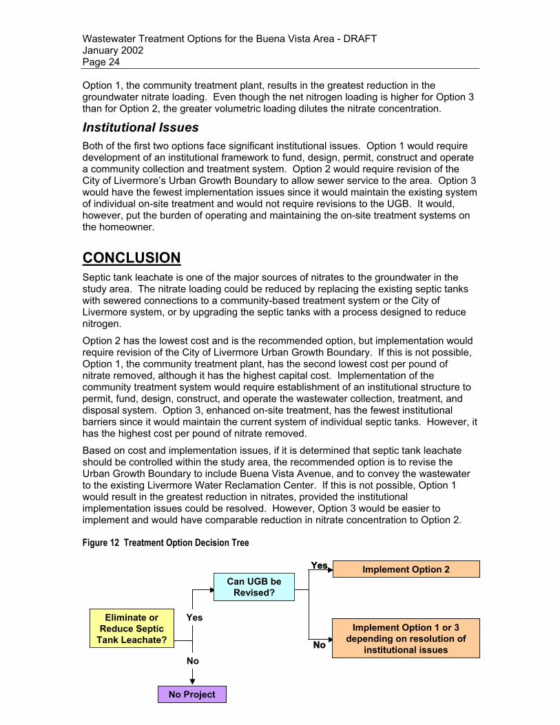
CONCLUSION Septic tank leachate is one of the major sources of nitrates to the groundwater in the study area. The nitrate loading could be reduced by replacing the existing septic tanks with sewered connections to a community-based treatment system or the City of Livermore system, or by upgrading the septic tanks with a process designed to reduce nitrogen. Option 2 has the lowest cost and is the recommended option, but implementation would require revision of the City of Livermore Urban Growth Boundary. If this is not possible, Option 1, the community treatment plant, has the second lowest cost per pound of nitrate removed, although it has the highest capital cost. Implementation of the community treatment system would require establishment of an institutional structure to permit, fund, design, construct, and operate the wastewater collection, treatment, and disposal system. Option 3, enhanced on-site treatment, has the fewest institutional barriers since it would maintain the current system of individual septic tanks. However, it has the highest cost per pound of nitrate removed. Based on cost and implementation issues, if it is determined that septic tank leachate should be controlled within the study area, the recommended option is to revise the Urban Growth Boundary to include Buena Vista Avenue, and to convey the wastewater to the existing Livermore Water Reclamation Center. If this is not possible, Option 1 would result in the greatest reduction in nitrates, provided the institutional implementation issues could be resolved. However, Option 3 would be easier to implement and would have comparable reduction in nitrate concentration to Option 2.
Figure 12 Treatment Option Decision Tree Yes Implement Option 2Yes Implement Option 2
Eliminate or Reduce Septic
Tank Leachate?
No Project
Yes
No
Can UGB be Revised?
No
Implement Option 1 or 3 depending on resolution of
institutional issues
Eliminate or Reduce Septic
Tank Leachate?
No Project
Yes
No
Can UGB be Revised?
No
Implement Option 1 or 3 depending on resolution of
institutional issues


