36
Operating instructions POWER LIFTKET Electric chain hoists Please do not use the hoist until all operators have carefully read this manual and have signed the form on the last page.

Operating instructions POWER LIFTKET Electric chain hoists
Please do not use the hoist until all
operators have carefully read this manual and have signed the form on the last page.

2
LIFTKET Hoffmann GmbH Dresdener Straße 64-68 04808 Wurzen / Germany +49-3425-89 24-0 +49-3425-89 24-99 [email protected] www.liftket.de Ho 10/2017 deutsch Originalbetriebsanleitung © 2017

3
Contents
1 Safety advice ............................................................................................................................................... 5 1.1 European Regulations ................................................................................................................................. 5 1.2 Advice for the use of electric chain hoists .................................................................................................... 6 1.3 Prohibitions on use ...................................................................................................................................... 7 1.4 Directions for use ......................................................................................................................................... 7 1.5 Spare parts .................................................................................................................................................. 7
2 Technical overview ...................................................................................................................................... 8 2.1 Assembly options......................................................................................................................................... 8 2.2 Explanation of type designation ................................................................................................................... 8 2.3 Sectional view .............................................................................................................................................. 9 2.4 Illustration of the load chain configuration .................................................................................................. 10
3 Assembly ................................................................................................................................................... 10 3.1 Mechanical assembly ................................................................................................................................ 10 3.1.1 Hook tackle ................................................................................................................................................ 10 3.1.2 Hook block ................................................................................................................................................. 11 3.1.3 Stationary electric chain hoists .................................................................................................................. 11 3.1.3.1 Hoist suspension with suspension plate .................................................................................................... 11 3.1.3.2 Hoist suspension with single hole suspension plate .................................................................................. 12 3.1.4 Gear ventilation.......................................................................................................................................... 13 3.1.5 Mounting the chain box .............................................................................................................................. 13 3.1.6 Assembling the load chain - single fall version .......................................................................................... 14 3.1.7 Assembling the load chain – double fall version ........................................................................................ 15 3.1.8 Replacing the load chain, chain guide and hold-down ............................................................................... 16 3.2 Electric connections ................................................................................................................................... 18 3.2.1 Connection to the mains power supply (three phase mains rotating clockwise) ........................................ 18 3.2.1.1 Low voltage control (auxiliary circuit control) ............................................................................................. 18 3.2.2 Electric limit switches for lift limitation ........................................................................................................ 19
4 Electric chain hoist with electric trolley ....................................................................................................... 19 4.1 Single fall operation ................................................................................................................................... 20 4.2 Double fall operation .................................................................................................................................. 20 4.3 Mechanical assembly ................................................................................................................................ 21 4.4 Electric connection of trolleys .................................................................................................................... 22
5 Tests .......................................................................................................................................................... 22 5.1 Test when used according to BGV D8, section 23 .................................................................................... 22 5.2 Test when used according to BGV D6, section 25 .................................................................................... 22 5.3 Regular tests ............................................................................................................................................. 23
6 Maintenance .............................................................................................................................................. 23 6.1 Maintenance and checks ........................................................................................................................... 23 6.2 Construction of DC disc brake ................................................................................................................... 24 6.2.1 Installation of the brake .............................................................................................................................. 24 6.2.2 Electric control of the brake ....................................................................................................................... 25 6.2.3 Faults on brake .......................................................................................................................................... 25 6.2.4 Checking brake functioning ....................................................................................................................... 25 6.3 Safety clutch .............................................................................................................................................. 25 6.3.1 Construction of slipping clutch ................................................................................................................... 26 6.3.2 Adjustment of the sliding clutch ................................................................................................................. 26 6.3.3 Checking the release limit of the sliding clutch during regular inspections ................................................ 27 6.4 Load chain ................................................................................................................................................. 27 6.4.1 Lubricating the load chain before starting and during operation ................................................................ 27 6.4.2 Checking the wear of the load chain .......................................................................................................... 28 6.4.3 Measuring wear and replacing chain ......................................................................................................... 28 6.5 Maintenance work on trolley ...................................................................................................................... 28 6.5.1 Air gap adjustment of trolley brake ............................................................................................................ 28

4
7 Duty rate of an electric chain hoist ............................................................................................................ 29 7.1 Short-time duty .......................................................................................................................................... 29 7.2 Intermittent duty ......................................................................................................................................... 29 7.3 Example .................................................................................................................................................... 29
8 Duty rate of the electric trolleys ................................................................................................................. 30
9 Strainer clamp for the control cable ........................................................................................................... 30
10 Lubrication ................................................................................................................................................. 31 10.1 Lubrication of the gear ............................................................................................................................... 31 10.2 Lubrication of the chain ............................................................................................................................. 31 10.3 Lubrication of the hook block and hook tackle ........................................................................................... 31 10.4 Lubrication of the trolleys .......................................................................................................................... 32 10.5 Auxiliary materials ..................................................................................................................................... 32
11 Measures to be taken at the end of the S.W.P. ......................................................................................... 33
12 Example of Declaration of Conformity ....................................................................................................... 34
13 Example of Declaration of Incorporation ................................................................................................... 35

5
1 Safety advice 1.1 European Regulations The following regulations, and all recommendations of this manual serve as basis for assembly, installation, certification and maintenance of electric chain hoists, within Germany and within the area of the European community. For countries other than mentioned, local legislation and directives may apply in addition to the regulations as stated in this manual (German/European). Please pay particular attention to the rules for the prevention of accidents and the statutory regulations.
European Regulations
2006/42/EC EC-Machine directive
2014/30/EC EC-Directive relating to electromagnetic compatibility
2014/35/EC EC-electrical equipment designed for use within certain voltage limits
BGV accident prevention regulations
DGUV Vorschrift 1 (BGV A1:2009) Principles of prevention
DGUV Vorschrift 3 (BGV A3:2005) Electrical facilities and equipment
DGUV Vorschrift 52 (BGV D6:2000) BGV accident prevention regulation for use in crane systems
DGUV Vorschrift 54 (BGV D8:1997) BGV accident prevention regulation for electric winches, lifting and pulling equipment
DGUV Regel 100-500 (BGR 500-2.8:2008) Hoisting accessories
DGUV Grundsatz 309-001 (BGG 905:2004) Checking of cranes
Harmonized regulations
DIN EN ISO 12100:2010 Safety of machinery
DIN EN 14492-2:2006+A1:2009 Cranes - Power driven winches and hoists
DIN EN 818-7:2002+A1:2008 Short link chain for lifting purposes; Fine tolerance hoist chain, Grade T
DIN EN ISO 13849-1:2008 Safety of machinery - Safety-related parts of control systems; General principles for design
DIN EN 60034-1:2010 Rotating electrical machines; Rating and performance
DIN EN 60034-5:2001+A1:2007 Rotating electrical machines; Degrees of protection provided by the integral design of rotating electrical machines
DIN EN 60204-1:2006 Electrical equipment of machines; General requirements
DIN EN 60204-32:2008 Electrical equipment of machines; Requirements for hoisting machines
DIN EN 60529:1991+A1:2000 +A2:2013 Degrees of protection provided by enclosures (IP-Code)
DIN EN 60947-1:2007+A1:2011 Low-voltage switchgear and control gear
DIN EN 61000-6-2:2005 Electromagnetic compatibility, Immunity for industrial environments
DIN EN 61000-6-3:2007+A1:2011 Electromagnetic compatibility, Emission standard for residential, commercial and light-industrial environments
DIN EN 61000-6-4:2007+A1:2011 Electromagnetic compatibility, Emission standard for industrial environments
DIN EN 82079:2013 Preparation of for use, structuring, content and presentation
Standards and technical specifications
FEM 9.511:1986 Hoist gearing classification
FEM 9.683:1995 Series lifting equipment; Selection of hoisting and travelling motors
FEM 9.751:1998 Series lifting equipment; Power driven series hoist mechanisms; Safety
FEM 9.755:1993 Serial hoist units; Measures for achieving safe working periods
The producers guarantee depends on consideration of these regulations and all of this manual. Other national regulations are valid for countries outside of the European community.

6
1.2 Advice for the use of electric chain hoists Electric chain hoists are designed to lift and to lower the loads vertically and to travel horizontally with those lifted loads (with trolleys). Any other use is not considered to be proper. Manufacturer does not take responsibility for any improper use and the risk is on the operator’s responsibility. For use of the hoist in an aggressive environment – please consult the producer. To this effect, it may be necessary to make certain components from different materials. The electric chain hoist can only be operated by personnel, who have complete knowledge of this manual, and have unhindered access to it. Do not operate the electric chain hoist until all operators have thorough knowledge of this manual, and acknowledge that by signing the allocated field on the rear cover of this brochure. If properly used, the modern design of the electric chain hoists guarantees safety and economic operation. The safety friction clutch is located between gearbox and brake, which enables stopping the load without putting strain on the clutch.
Before first use make sure, that all electrical wires are connected in accordance with the instructions, that all wires are without damages and that the whole equipment could be switched off by a main switch. It is the responsibility of the operator to make sure that all suspension points of the hoist are designed to safely withstand the dynamic forces caused by the lifting equipment. The chain hoist can only be used when it is suspended according to specification and the outgoing chain can leave the hoist safely, by its own weight, in the relevant direction. Therefore, the container for the dead end of the chain outside the hoist must be big enough to allow the chain to come out. If not, the chain can be trapped inside the hoist and can break the casing of the hoist.
Maintenance work on hoisting equipment has to be carried out by trained and authorised people only. The main switch has to be switched off and the working area is to be secured beforehand.
Authorised people have to have a theoretical training as well as experience in the field of winches, lifting and pulling equipment or cranes. They have to possess an excellent knowledge of the relevant work safety regulations, directives, and general accepted rules of lifting techniques, which enables them to decide whether the lifting equipment is in a safe working condition or not. IEC 364 or DIN VDE 0105 regulations, for example, prohibit that untrained personnel perform any work on power equipment. Any maintenance work and inspections are to be entered into the crane inspection book (e.g. brake or clutch adjustments). This manual will tell you how to operate the hoist and how to handle its suspension or its loads safely. The following safety advices have to be observed. The safety instructions may not be complete for each mode of use. If there are any questions or problems contact the manufacturer or our local representative. This Operating Instructions should always be in a complete and fully readable condition. No responsibility is taken for damages and operating troubles due to the following reasons:
• improper use
• unauthorised modification of the drive system
• unworkmanlike work done on the system and with the system
• operating errors
• Failure to use the product as instructed in the manual

7
1.3 Prohibitions on use
• Using the hoist to carry people is strictly prohibited!
• Inching mode (fast switching on / off of functions)
• Permanent run against the rubber buffers of the lowest and highest hook position (ultimate safety limit for emergency only)
• Using the hoist with people being underneath the load
• Moving loads heavier than the nominal load
• Pulling loads which are tilted or dragging loads
• Tearing off loads
• Removing the cover of vessels which are under vacuum
• Moving a trolley by pulling the control pendant or the control cable, even if these are relieved of strain
• Using the lifting chain to sling the loads
• Using a lifting chain, which is longer than the chain box capacity stated under the box
• Starting initial operation before an expert or a trained specialist has inspected the equipment.
• Carrying out repairs without cutting off current supply and without special knowledge
• Using the hoist with higher duty rate as marked on the specification plate
• Using the hoist without having done the regular inspection
1.4 Directions for use
• The load may only be moved if it is slung securely and no person is standing near enough to be at risk.
• The load must be placed vertically under the electric hoist before lifting.
• The motion directions are indicated with symbols on the control buttons.
• Do not turn the chain over edges.
• Do not lower the double fall hook until the chain gets slack.
• Consult the manufacturer, if the hoist is to be used in an aggressive environment
• Consult the manufacturer, when transporting red-hot melts or similar dangerous materials.
• Repair work can be done by specialists only if mains supply is switched off and secured and no load is suspended on the hook.
• After an emergency stop button actuation, the cause of actuation has to be found and all possible failures removed by expert personnel. Reset emergency pushbutton only after this procedure.
• Lifting the load from the ground has to be done with the lowest possible speed. Before doing this slack sling chains or ropes have to be tightened carefully.
• When operating hoist at a height that is reachable by hand, do not touch the hoist, where load chain enters the unit. Proper safety measures have to be established to avoid this risk.
1.5 Spare parts Only original fixing components, spare parts and accessories, listed in manufacturer’s spare parts catalogue, are acceptable for use. The producers guarantee is given for those spare parts only. The producer cannot be held responsible for any damages due to the use of non-original parts and accessories.

8
2 Technical overview 2.1 Assembly options The simple building block system makes it easy to convert an electric chain hoists to different versions. This allows the choice of single or double – fall versions, stationary or mobile with push or electric trolleys, and the installation of greater hoisting and operating heights. two-hole suspension plate with connecting traverse hook tackle
electric trolley one-hole suspension plate hoisting gear chain box with securing chain lift limiter hook block
Figure 1: assembly options 2.2 Explanation of type designation version 235/50 type 25.000 / 2 -3.2 / 0.8 slow lifting speed [m/min] main lifting speed [m/min] number of falls load capacity [kg]

9
2.3 Sectional view Fig. no. Description 1 Hoist body 2 Gear cover 3 Pinion shaft 1 4 Brake unit 5 Cap for auxiliary circuit 6 Clutch unit 7 Lifting motor 8 Sprocket wheel 9 Cap for limit switch
5 4 3 1 6 7
2 8 9 Figure 2: sectional view

10
2.4 Illustration of the load chain configuration Use only original chain of the manufacturer! Only these original chains meet the high stress and service life standards required.
hold-down chain sprocket chain guide lift limiter (limit stop) hook tackle hook block
Figure 3: single fall version two fall version 3 Assembly Assembly work should only be carried out by trained specialist in accordance with DGUV V54 (BGV D8) §24. 3.1 Mechanical assembly 3.1.1 Hook tackle The hook tackle is used to attach loads for hoists in single fall version. 4 hexagonal socket head cap screw DIN 912 M16×70 – 8.8 MA = 174 Nm spring washer DIN 7980 A8-FSt
hook nest pin hook nest cover load hook, complete (with hook nut, pressure bearing, and safety latch)
Figure 4: design of the hook tackle During maintenance, please check the condition of the hook (wear, centre distance), pressure bearing, safety latch and hook nut. Caution!
Hook nut of the hook tackle is secured by a split pin inserted at right angle to the shaft.

11
3.1.2 Hook block The hook block is used to attach the load in double fall version. side of hook block chain sprocket shaft with plain bearing load hook, complete with pressure bearing and hook nut
4 hexagonal head screws DIN 912 M16 x 120 - 8.8 MA=174Nm 4 self-locking nuts DIN 985 M16 - 8
Figure 5: details of the hook block During maintenance, please check the condition of the hook (wear, centre distance), pressure bearing, safety latch and hook nut. Caution!
Hook nut of the hook block is secured by a securing insert located on the top of the nut.
3.1.3 Stationary electric chain hoists 3.1.3.1 Hoist suspension with suspension plate Assembly: Place the suspension plate into suspension nest, specially provided on the electric chain
hoist body, and pin it in into place by two pins. Fit the securing plates and secure them by socket head cap screws complete with spring washers.
suspension plate pin Ø 42 mm securing plate for Ø 42 mm pin hex. socket hd. cap screw DIN 912 M10x25-8.8, MA=42Nm spring washer DIN 7980 A10-FSt securing plate for Ø 55 mm pin hex. socket hd. cap screw DIN 912 M12x25-8.8, MA=72Nm spring washer DIN 7980 A12-FSt pin Ø 55 mm
Figure 6: suspension with suspension plate

12
3.1.3.2 Hoist suspension with single hole suspension plate Assembly: Place the suspension plate into suspension nest, specially provided on the electric chain
hoist body, and pin it in into place by two pins. Fit the securing plates and secure them by socket head cap screws complete with spring washers.
single hole suspension plate pin Ø 42 mm securing plate for Ø 42 mm pin hex. socket head cap screws M10×25-8.8 DIN 912, MA=42Nm spring washer DIN 7980 A10-FSt securing plate for Ø 55 mm pin hex. socket head cap screws M10×25-8.8 DIN 912, MA=42Nm spring washer DIN 7980 A12-FSt pin Ø 55 mm
Figure 7: hoist suspension with single hole suspension plate Caution! The single hole suspension plate is designed so that centre of suspension hole fall in line with centre of gravity of the load both in case of single and double fall versions. The right fixing hole is marked by a symbol. When changing the number of chain falls of hoist, which is fitted with a single hole suspension plate, the suspension point has to be selected to fall in line with the centre of gravity of the load.
Figure 8: load centre of gravity with single and double fall version
hock block label
hock holder label
load centre of gravity with single fall operation load centre of gravity with double fall operation

13
3.1.4 Gear ventilation After the completion of hoist installation, a special washer has to be placed under the oil filler plug (top side of casing) to avoid oil leakage due to high pressure inside the gearbox. You will find this washer fastened with a piece of self-adhesive tape next to the oil filler plug.
Figure 9: special washer for the oil filler plug 3.1.5 Mounting the chain box The chain box is held in position by a DIN 931 M20×200-8.8 screw, which is secured by a M20 DIN 985-8 self-locking nut. To secure chain box into place or adjust its position, fit the securing chains as follows:
• Insert the chain end links of each securing chain (7x22 mm) in between the lugs on chain box and fix them by DIN 931 M8×35-8.8 hex. head screws and M8 DIN 985-8 self-locking nuts.
• The securing chains have to be fixed on suspension eye. The securing chains are connected by shackles and they are fixed on the suspension eye by the lugs and the 12x80 DIN 1433 bolts.
• Make ensure that securing chains are tight and not twisted after fitting. Important! Ensure that the chain box is sufficient large for the amount of chain you are using. See
the chain dimension and capacity markings shown on the side of the chain box. Insert the chain end with lift limiter loosely into the chain box. After running the entire chain length through the hoist into the chain box, check that the box is not overloaded (see capacity mark at the chain box). Do not overload the chain box. Take care that load holding elements do not contact or hit the chain box.
hex. head screw with self-locking nut chain box
suspension plate lugs and fastening bolts securing chains hex. head screws with self-locking nuts chain box
Figure 10: Mounting the chain box
maximal Kette / chain
23/20 Kette 23,5x66 max. 20 m
oil filler plug special washer

14
3.1.6 Assembling the load chain - single fall version load chain hook tackle
hold-down chain guide chain sprocket driving shaft pre-assembled piece of chain (assembly aid) open chain-link on the chain box side load chain lift limiter
Figure 11: assembling the load chain – single fall version 1. There is a short pre-assembled piece of chain on the chain driving sprocket of new units. 2. Always place the open chain link on the chain box side of the pre-assembled piece of chain and hook on the load
chain. 3. Feed in the load chain by actuating control buttons. 4. Remove the pre-assembled chain piece and the open chain link. 5. Fit the hook tackle to the end of load chain. 6. Lower the hook to its lowest position. 7. Attach the lift limiter* onto the 3rd link of the dead end. 8. Assemble chain box according to chapter 3.1.5. 9. Allow the chain to run into the chain box and lubricate the entire length of the chain Caution! When feeding in load chain or changing the number of chain falls, never let the old chain
to run completely out of the chain hoist body. Hook on the new load chain or a chain piece on its end by an open link. After feeding in the new load chain, remove open chain link and chain piece (observe instructions specified in chapter 3.1.8!)
Let the dead end of chain run into the chain box by pressing the up button and using the hoist motor (not by hand) to prevent knots inside the chain box. Allow filling of the chain box only by running the chain through the hoist by using the motor. * Lift limiter The lift limiter actuates a limit switch, which determines the lowest position of load hook and prevents the dead end of chain running out of the hoist. When the limit switch malfunctions, lift limiter acts as an emergency limiter together with the slipping clutch. This emergency limit stop, however, cannot be used in normal operation.

15
3.1.7 Assembling the load chain – double fall version
hold-down sprocket wheel chain guide pre-assembled piece of chain (assembly aid) open chain-link on the chain box side vertical chain link load chain lift limiter
Figure 12: assembling the load chain – double fall version 1. First feed the load chain into the hoist body (as described in chapter 3.1.6). 2. Pull the chain through the hook block using the pull in-wire (special tool). Caution! Never allow the chain to be twisted between the chain outlet and the hook block! If the
assembly, according to Figure 12, is not possible without a twisted chain, one chain link has to be cut and removed to allow correct assembly or installation has to be performed with 2 slotted chain links.
3. Remove the pre-assembled chain piece and the open chain link. 4. Unscrew DIN 912 M10x25-8.8 socket head cap screws of the shaft securing plate. 5. Remove both chain fixing pin.
Pull the chain end starting with vertical chain link from the hook block and push it into the cross shaped chain hole, which is on the bottom of hoist casing. Take care not to let the chain get twisted.
6. Reinsert chain end fixing pins. 7. Fit securing plates with DIN 912 M10×25-8.8 (MA=42Nm) socket head cap screws. 8. Recheck that the chain is not twisted. 9. Lower the hook to its lowest position. 10. Attach the lift limiter onto the 3rd link of the dead end. 11. Assemble chain box according to chapter 3.1.5. 12. Allow the chain to run into the chain box and lubricate the entire length of the chain Caution!
Please take into account directions for use described in chapter 1!
hex. socket head cap securing plate screws for fixing shaft securing plate
chain end fixing pin

16
3.1.8 Replacing the load chain, chain guide and hold-down When replacing load chain, the chain guide and the hold-down must also be changed.
hold-down sprocket wheel chain guide (two parts) chain end fixing pin
chain guide fixing screw
limit switch shafts
chain end fixing pins
shaft securing plate for securing pin
open chain link
chain piece
Figure 13: replacing the load chain, chain guide and hold-down Single fal l operat ion Removal of worn load chain 1. Dismantle chain box. 2. Remove hook tackle from load chain by unscrewing 4 pcs. of DIN 912 M16×70 socket head cap
screws (see section 3.1.1) 3. Dismantle lift limiter from the unloaded chain end by unscrewing 4 pcs. of DIN 912 M12×70 socket
head cap screws. 4. Hook the feed-in chain piece to the hook side of load chain using an open chain link. 5. Run the worn load chain out of the unit by actuating up-switch. 6. Run the load chain out of hoist body until pre-assembled chain piece is still remains on the chain
sprocket. 7. Unhook worn load chain from pre-assembled chain piece.
Replacing the load chain and hold-down 8. Remove the cover of limit switches by unscrewing 5 pcs. of DIN 912 M8x80-8.8 hex. socket head
cap screws. 9. Removal of limit switch shafts in the following order:
Unscrew DIN 912 M5×35-8.8 hex. socket head cap screws (2-off) of the limit switch shafts.
Remove retainer rings and spring of rotating fork.
Pull out the limit switch shafts. 10. Unscrew DIN 912 M20x140-8.8 screws (2-off) of the chain guide located in the limit switch
compartment. 11. Remove chain guide (from the bottom of the housing) 12. Press the hold-down out of its position, using a screwdriver. 13. Fit the new hold-down and new chain guide (Tightening torque of DIN 912 M20x140 mounting screws (2-off) should not exceed 60 Nm. 14. Refit limit switch shafts (see section 3.2.2) 15. Refit limit switch cover.

17
Replacing load chain 16. Always place the open chain link on the chain box side of the pre-assembled piece of chain and
hook on the new load chain. 17. Feed in the load chain by inching the pendant. 18. Remove the pre-assembled chain piece and the open chain link. 19. Fit the hook tackle to the end of load chain. 20. Lower the hook to its lowest position. 21. Attach the lift limiter onto the 3rd link of the dead end. 22. Fit on chain box according to section 3.1.5. 23. Allow the chain to run into the chain box and lubricate the entire length of the chain
Caution!
If the chain has completely run out of the hoist housing, loosen the clutch before fitting the new chain and readjust it after the chain has been fitted.
Double fal l operat ion Removal of worn load chain 1. Dismantle chain box. 2. Unscrew DIN 912 M10x25-8.8 fixing screws (4-off), dismantle shaft holders and remove chain end
fixing pins. 3. Dismantle lift limiter from the unloaded chain end by unscrewing DIN 912 M12×70 hex. socket
head cap screws (4-off). 4. Hook the feed-in chain piece to the hook side of load chain using an open chain link. 5. Run the worn load chain out of the unit by actuating pendant switches. 6. Run the load chain out of hoist body until pre-assembled chain piece is still remains on the chain
sprocket. 7. Unhook worn load chain from pre-assembled chain piece.
Replacing the load chain and hold-down 8. Remove the cover of limit switches after unscrewing 5 pcs. of DIN 912 M8x80-8.8 hex. socket
head cap screws. 9. Removal of limit switch shafts in the following order:
Unscrew DIN 912 M5×35-8.8 socket head cap screws (2-off) of the limit switch shafts.
Remove retainer rings and spring of rotating fork.
Pull out the limit switch shafts. 10. Unscrew DIN 912 M20x140-8.8 screws (2-off) of the chain guide, which is located in the limit
switch compartment. 11. Remove chain guide (from the bottom of the housing) 12. Press the hold-down out of its position, using a screwdriver. 13. Fit the new hold-down and new chain guide (Tightening torque of DIN 912 M20x140 mounting screw (2-off) should not exceed 60 Nm. 14. Refit limit switch shafts (see section 3.2.2) 15. Refit limit switch cover.
Replacing load chain 16. Always place the open chain link on the chain box side of the pre-assembled piece of chain and
hook on the new load chain, starting with vertical chain link. 17. Feed in the load chain by actuating the pendant switch. 18. Remove the pre-assembled chain piece and the open chain link. 19. Pull the chain through the hook block using the pull-in wire (special tool).
Caution! Never allow the chain to be twisted between the chain outlet and the hook block! If the assembly, according to Figure 12, is not possible without a twisted chain, one chain link has to be cut and removed to allow correct assembly.
20. Pull the chain end from the hook block and push it into the cross shaped chain hole, which is on the bottom of hoist casing. Take care not to let the chain get twisted.
21. Reinsert chain end fixing pins. 22. Fit securing plates with DIN 912 M10×25-8.8 (MA=42Nm) hex. socket head cap screws. 23. Recheck that the chain is not twisted. 24. Lower the hook to its lowest position. 25. Attach the lift limiter onto the 3rd link of the dead end. 26. Fit on the chain box properly. 27. Allow the chain to run into the chain box and lubricate the entire length of the chain
Caution!
If the chain has completely run out of the hoist housing, loosen the clutch before fitting the new chain and readjust it after the chain has been fitted.

18
3.2 Electric connections Electrical installation must comply with EN 60204-32 or relevant national regulations. After having completed the installation, checks have to be executed in accordance with the European Regulation EN 60204–1, section 20.2 and section 20.3. Details of the control can be seen in the wiring diagram. The electric installation complies with the currently valid EN 60204 part -32 standard.
3.2.1 Connection to the mains power supply (three phase mains rotating clockwise) The mains power supply (main incoming line cable) must be able to be disconnected at all poles by means of a mains switch (in accordance with EN 60204-32 section 5.3). Work on the electric installation may only be carried out by trained specialists and the equipment must first be disconnected from the mains power supply. Fuses (slowly blowing) at 400 V (~) before main switch should have 63 A rating. Check if the mains voltage complies with that specified on the type plate. Connect mains supply lines and control cables in accordance with the wiring diagram. The L1, L2, L3 and PE terminals for the mains connection are located in the control box. Line 3 + PE cable (minimum cross section 4 mm2) are necessary for the connection. After connection, press the lifting button. If the load moves downwards, swap L1 and L2 supply wires (cut off power supply before swapping)
3.2.1.1 Low voltage control (auxiliary circuit control)
power cable - motor contactor rectifier A1 control transformer T mains connection 4 G 4
power cable – trolley motor protection switch fuses primary / secondary F1/F2 terminal strips hoisting brake Control cable Strainer clamp
Figure 14: low voltage control The control transformer T supplies control circuit with 24 V AC control voltage. Other secondary voltages are available on request.

19
3.2.2 Electric limit switches for lift limitation The electric chain hoists are equipped with electric limit switches to limit the uppermost and lowest position of the hook. Distance between limit switch cam and limit switch can be adjusted by shifting the switch, and its value should not exceed 1 mm. When commissioning hoists, make sure that symbols on the switches comply with direction of hook movement.
limit switch Lowering limit switch Lifting limit switch cam hook tackle or hook block lift limiter
Figure 15: electric limit switches for lift limitation 4 Electric chain hoist with electric trolley All trolleys are suitable for
• Flanges with small width in accordance with DIN 1025 and European regulations 24-62
• Flanges with medium width in accordance with DIN 1025
• Flanges with large width in accordance with DIN 1025
The trolley can be fitted with an electric cross limit switch at the level with the centre of trolley wheels. Electric trolley of type 235/… hoist is not suitable for curved tracks! Additionally load conditions of bottom flange of support beam has to be checked by a structural engineer and has to comply with FEM 9.341.

20
4.1 Single fall operation In case of single fall operation (max. 12,5 t), the electric chain hoist is fixed to the electric trolley by a suspension plate. Electric chain hoists supplied with a 12,5 t capacity trolley can not be converted to two fall operation.
trolley motor trolley pin suspension plate suspension pin with securing plate hook tackle
Figure 16: electric chain hoist with electric trolley 4.2 Double fall operation In case of double fall operation, two 12,5 t capacity electric trolley are used to carry the chain hoist. In this operation mode with maximum 25 ton load capacity, four traverses distribute load evenly on two trolleys.
trolley motor trolley pin traverse pin suspension plate suspension pin with securing plate hook block
Figure 17: hoisting gear with electric trolley
21
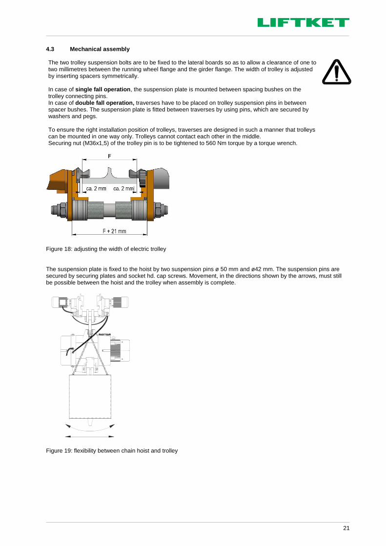
4.3 Mechanical assembly The two trolley suspension bolts are to be fixed to the lateral boards so as to allow a clearance of one to two millimetres between the running wheel flange and the girder flange. The width of trolley is adjusted by inserting spacers symmetrically. In case of single fall operation, the suspension plate is mounted between spacing bushes on the trolley connecting pins. In case of double fall operation, traverses have to be placed on trolley suspension pins in between spacer bushes. The suspension plate is fitted between traverses by using pins, which are secured by washers and pegs. To ensure the right installation position of trolleys, traverses are designed in such a manner that trolleys can be mounted in one way only. Trolleys cannot contact each other in the middle. Securing nut (M36x1,5) of the trolley pin is to be tightened to 560 Nm torque by a torque wrench.
Figure 18: adjusting the width of electric trolley The suspension plate is fixed to the hoist by two suspension pins ø 50 mm and ø42 mm. The suspension pins are secured by securing plates and socket hd. cap screws. Movement, in the directions shown by the arrows, must still be possible between the hoist and the trolley when assembly is complete.
Figure 19: flexibility between chain hoist and trolley

22
4.4 Electric connection of trolleys The contactors for controlling the trolley motor are located in a special contactor box. This control box is fixed to the side- plate of trolley (on the motor side) by two DIN 912 M8×10 socket head cap screws. Connect the leads of the cable protruding from the contactor box to the right terminals in terminal compartment of the electric chain trolley in accordance with the wiring diagram. After electric connection, check that the electric chain hoist and trolley are working correctly. In case of double chain fall operation, the second trolley is to be connected to the first trolley by a connection cable in accordance to wiring diagram. There is a separate cable screw connector for this purpose in the auxiliary control box of the first trolley. trolley 1 trolley 2 connection cable hoist - trolley terminal box on lifting motor connecting cable to the mains
terminal box trolley motor control box trolley auxiliary control in the hoist pendant cable with strainer clamp
Figure 20: electric connection of trolleys Explanation of trolley type designation EF N / 12.5 t / 4+16 EF – electric trolley
flange width N and S1
load capacity in ton.
travelling speed in m/min
5 Tests Use of the electric chain hoist is possible in accordance with:
• Accident prevention regulations for Winches, lifting and pulling equipment DGUV V 54 (BGV D8)
• UVV Cranes DGUV V 52 (BGV D6) The dynamic and static tests are accomplished acc. to EC Machinery Directive by manufacturer. 5.1 Test when used according to DGUV V 54 (BGV D8 § 23) A trained specialist must test the equipment before starting operation for the first time and after extensive alterations. 5.2 Test when used according to DGUV V 52 (BGV D6 § 25) An authorised person must test the cranes before starting operation for the first time and after extensive alterations. The electric chain hoists are type approved.
connection cable trolley 1 and trolley 2

23
5.3 Regular tests
• A trained specialist must test the equipment, cranes and supporting structures once a year. It may be necessary to carry out tests more often if the operating conditions are very harsh, that means for example high percentage of use with full load, dusty or aggressive environment, high duty rate, high number of operation cycles. With this inspection, the remaining time of use is to be determined and recorded in accordance with FEM 9.755.
• Only an authorised person appointed by the BG - associations and experts from the Technical Control Association (TÜV) are considered qualified to test cranes.
• Trained specialists are highly qualified specialist personnel or the manufacturer’s after-sales service personnel. 6 Maintenance
• All maintenance work must be carried out by trained specialists.
• The maintenance table (Table 1) lists the parts and functions to be checked and the necessary maintenance work. Malfunctions have to be reported immediately, in writing, to the owner, who initiate repair work to be carried out by a trained specialist.
• All repair work must be carried out on unloaded equipment, after power supply is cut off by main switch.
• Shorten the periods between maintenance works in very harsh operating conditions, e.g. multi-shift operation, high number of switch actuation, poor environmental conditions.
Checking for wear
• Check suspension hook and load hook for possible deformation (measure punch spacing), cracks, corrosion and general condition.
• The chain sprocket in the hook block must be replaced if the running surface is worn by about 1mm.
• Check the wear of the load chain in accordance with chapter 6.4.2.
6.1 Maintenance and checks Please note points described in chapter 1.2 ! The following regular maintenance periods are for reference, which has to be shortened, if the hoist is working under hard conditions (two or three shifts, high percentage of lifting with nominal load, dusty or high temperature environment).
Check
daily 3 monthly yearly
Visual check of the whole equipment ●
Function check of the brake ●
of the lift limiter ●
Maintenance and adjustment of the brake 30 operating hours
Slipping clutch ●
Wear of the load chain (chapter 6.4.2) ●
Lubrication of the load chain ●
Lubrication of the hook tackle and hook block in accordance with chapter 10.3, and condition of safety latch
●
Checking hook nut locking ●
General checks of all screws ●
chain guide / hold-down ●
locking elements ●
Condition and fixing of chain box ●
Check of control cable, power supply cable and pendant control ●
Check of the trolleys and wheels ●
Table 1: maintenance and checks The electric chain hoist is designed in accordance with FEM 9.511. If the hoist is used under the con-ditions of FEM 9.511, including the described frequency of maintenance work, the electric chain hoist must be overhauled after 10 years.

24
6.2 Construction of DC disc brake
Brake type Screws DIN 912
Tightening torque [Nm]
Nominal power P [W]
Air gap SL
nominal [mm] Air gap SL max. [mm]
BFK 458-16 3×M8 23 55 0,3 0,75
ROBA-stop-M 100 3×M8 22 88 0,3 0,9
Table 2: brake types
Figure 21: construction of spring operated brake 6.2.1 Installation of the brake 1. Press the hub onto the shaft. 2. Assemble the clutch spring with adjusting nut and locking nut. 3. Assemble brake unit to the hub. 4. Mount the brake on the gear cover by 3 x M8 fixing screws. 5. Tighten the screws uniformly (tightening torque see table 2)
When ordering spare parts, the complete model designation has to be stated.
Mounting the brake onto the gear cover Tightening with a torque wrench Figure 22: installation of the brake Dismantling has to be done in the opposite order!
Air gap SL Magnetic coil Flange Rotor with friction linings Hub Plate Sticker label hex. socket head cap screws

25
6.2.2 Electric control of the brake Principle of operation The disc brake is supplied through a rectifier circuit. It operates according to the fail-safe principle. If there is a power failure, the brake is applied automatically so that the load is held securely in every position. To shorten the braking time the brake is operated in a DC circuit. The different methods of connection for a particular type of hoist can be seen in the respective wiring diagram. 6.2.3 Faults on brake Troubleshooting and fault elimination
Faults Causes Remedy
Brake does not release; air gap is not zero
Coil has contact to ground or between the windings
Replace the brake
Wiring wrong or defective Check connection and correct wiring to drawing
Rectifier defective or wrong Compare wiring at rectifier with wiring diagram; especially correct setting of the bridge. Measure DC - voltage between terminals 5 and 6. If differences occur change the rectifier
Air gap too large Replace the brake
Table 3: troubleshooting and fault elimination If rectifier defects occur repeatedly, the brake shall be replaced even if no winding short circuit can be detected. Defect may occur only in warm operating condition. 6.2.4 Checking brake functioning When breaking the nominal load during the lowering process, the load should be stopped after approx. two chain link lengths of travel, and the brake should not stop the load in a jerking manner.
6.3 Safety clutch The sliding clutch is located between the lifting motor and main pinion shaft and transmits the torque. As a secondary function, it limits the transmission of torque depending on the setting, hence limits the transmitted power. This way, it prevents overloading hoist and its support components.
A special advantage of the patented safety clutch is, that it is situated right after the motor shaft, before the brake. In case of heavy wear at the clutch lining, one would not see an uncontrolled downward movement of the load, because the load can be held at every point by the brake. The clutch unit acts as a sliding clutch with asbestos free linings. The clutch is easily adjustable and accessible. The wear resistant lining material doesn’t require re-adjustment under normal operational circumstances.

26
6.3.1 Construction of slipping clutch
Figure 23: construction of sliding clutch 6.3.2 Adjustment of the sliding clutch Adjusting the sliding clutch may only be performed by a trained or competent person. 1. Test load =1.1 times the nominal/rated load, or hook a clutch testing device to the load hook. 2. Switch on the electric chain hoist by pressing the lift button and check that the test load can be lifted or if the
clutch testing device shows approximately 1.3 times the nominal load. The accurate value for 1.3 factor depends on lifting speed.
3. Lower the test load to the floor. 4. Decrease or increase clutch torque until the test load is just lifted or the clutch testing device shows a required
value. 5. Adjustment of clutch torque:
a Unscrew and remove cover on the gear side (11). b Loosen the securing nut (10) on the adjustment nut (9). c Use a spanner or plier to hold the shaft firmly against rotation of tension rod (12). d Use a second spanner to loosen/tighten the adjusting nut (9) until the hoist just lifts required test load, or
the clutch testing device shows the required value. – Check the clutch setting by a short starting of the hoisting motor (press lift button shortly). – e Tighten the securing nut (10) on the adjustment nut (9). f Completion: Recheck the clutch torque by lifting the test load. g Refit cover on the gear side (11).
1 Main motor shaft 2 Clutch hub 3 Teeth ring 4 Drive disc with clutch
liner 5 Bearing 6 Clutch disk 7 Main pinion shaft 8 Compression spring
with plate 9 Adjusting nut 10 Locking nut 11 Gear side cover 12 Tension rod
1 2 3 4 5 6 7 8 9,10 11
12

27
11 9 10 12
Figure 24: adjustment of the sliding clutch The sliding clutch is factory set with the test load. After changing or replacing the lift motor, it is not necessary to reset the clutch. In such a case, checking with nominal load is satisfactory. The original distance between the end of the tension rod and the pressure plate of the coupling is marked on a tag on the brake coil.
Note: test load = nominal load (during regular inspections) 6.3.3 Checking the release limit of the sliding clutch during regular inspections The release limit of the sliding clutch has to be checked by a specialist during the yearly work safety inspection in accordance with §26, DGUV V 52 (BGV D6), or §23, DGUV V 54 (BGV D8). It should be checked whether the hoist lifts the nominal load! The hoist must not lift more, than 1,6 x nominal load. If test loads larger than nominal load are not available, then release limit of slipping clutch can be checked by a clutch testing device In this case, slipping limit should be approximately 1,3 x nominal load. After checking the release limit, verify again if the hoist lifts the nominal load. When measuring wrong release value, the sliding clutch has to be readjusted in accordance with chapter 6.3.2, and verification to chapter 6.3.3 has to be repeated. Adjustment value is to be recorded. 6.4 Load chain Hoist chains are means of carrying loads which require official approval. Therefore, it is important to observe the guidelines issued by the trade association’s centre for accident prevention with regard to round steel chains in hoisting operation, the guidelines for general inspection and test specifications in accordance with DIN 685, section 5, the accident prevention regulations in DGUV V 54 (BGV D8) and DGUV V 52 (BGV D6). 6.4.1 Lubricating the load chain before starting and during operation The links along the entire length of the load chain must be lubricated with 1:1 mixture of penetrating gear lubricant oil and molybdenum grease - before starting operation for the first time and during operation with no load. Subsequent lubrication, after cleaning the links first, depends on the frequency of use and the operating conditions. A dry-film lubricant, e.g. lubricating varnish, graphite powder, should be used when ambient influences are conducive to wear (sand, emery).

28
6.4.2 Checking the wear of the load chain The continuous monitoring of the load chain is compulsory according to DIN 685 section 5 and the accident prevention regulations in DGUV V 54 (BGV D8) § 27. The load chain must be checked before starting operation and regularly after every 70 operating hours or 3500 lifting/lowering cycles - under normal conditions, or more often under harsh and severe conditions. Checking must cover checking links, particularly at their points of contact, for wear, cracks, deformation and other damages.
The chain must be replaced:
• if the nominal thickness at the points of contact is reduced by 10%,
• if the chain or a link is elongated by 5 %, or measured over eleven links, the chain is elongated by 2%
• if the links are rigid When replacing load chain, the chain guide and the hold-down must also be changed. Caution! For replacement, use only original chains supplied by the manufacturer. 6.4.3 Measuring wear and replacing chain
Chain dimensions 23.5 × 66 mm
t dimension = max. 69.3 mm measured over one link
t dimension = max. 740.5 mm measured over 11 link
dm dimension = max. 21.15 mm
Formula:
2
21 dddm
Figure 25: measuring wear and replacing chain 6.5 Maintenance work on trolley The checks and maintenance work on the electric trolley have to be done in accordance with instructions specified for trolleys in Table 1. (Maintenance and checks).
6.5.1 Air gap adjustment of trolley brake If the brake linings are worn, so that air gap reaches the max. allowed 0.9 mm, then it is necessary to adjust the gap.
3 1 2 6 4 5
1. Dismantle the cover (1). 2. Loosen the fan fixing screws (2). 3. Remove the O-ring (3) and put a thickness gauge
0.25 mm between plate (4) and sticking plate (5). 4. Tighten the screw (6) so far that you can remove the
thickness gauge easily. Check the air gap at several places along the circumference.
5. Tighten the fan screws (2) uniformly. Tighten first the screws opposite the key (tightening torque 4-5.5 Nm).
6. Tighten the screw (6) again. 7. Remove the thickness gauge. 8. Replace the fan cover (1). 9. Carry out test run to verify the brake operation.
Figure 26: construction of the electric trolley brake

29
7 Duty rate of an electric chain hoist The duty rate and the number of operating cycles for one hour must not be exceeded (see FEM 9 682). The allowed duty rate is shown on the data plate of the electric chain hoist. The duty rate, expressed as the cyclic duration factor (c.d.f.) is the ratio of
s [m] 1 lifting lowering cycle Operating time break time Operating time break time Lifting Lowering t [min]
running time to running time + period of rest Formula:
ED %
total running time x 100%
total running time + total rest time
The duty rate is limited by the permissible temperature of the windings in the lifting motor. The running time is depending on the lifting height, lifting speed of the electric chain hoist and the number of lifting motions required for a particular transport procedure (unloading trucks, feeding machines). It is difficult in practice to take note of the duty rate during the lifting operation. We, therefore, give the following practical guidelines: 7.1 Short-time duty Permissible operating period without cooling interval after motor starts and with an initial motor temperature of about 20°C.
Duty group FEM 9 511
Duty group ISO 4301
Duty rate (ED %)
Short-time duty to FEM 9.683 (tB in min)
1 Bm M3 25 % 15
Table 4: duty rate in short-time duty This duty type is not permissible for the slow speed of hoisting motors. After having reached the maximum running time, a break is required, and the hoist can be further used in intermittent mode. 7.2 Intermittent duty
Duty rate (ED %) Break (min)
25 % 3 times running time
Table 5: necessary breaks depending on duty rate 7.3 Example The electric chain hoist type 12500/1-6,3/1,6 is used to lift loads of 12,500 kg to a height of 3 m. Performance data: Load 12500 kg Lifting speed 6.3 m/min - main lifting speed 1.6 m/min - slow lifting speed Duty rate 25 % - main lifting speed 10 % - slow lifting speed At the beginning of the lifting operation the electric chain hoist has a temperature of approx. 20 °C.
c.d.f. = = 0.95 min The hoist can be operated for approximately 20 min. without a break. This means
21 lifting/lowering cycles × 12500 kg load = 262500 kg transported load. After 20 minutes of operating time, 3 minutes break for each minute of operating time must be taken (i.e. 3 times the operating time). This break is usually necessary for slinging and taking off loads. Important!
Low lifting speed should only be used for precise lowering and lifting. Low lifting speed is not suitable when greater lifting heights should be achieved.
3 m (lifting) + 3 m (lowering) 6.3 m/min

30
8 Duty rate of the electric trolleys If the hoist is equipped with an electric trolley the operators have to take care of the duty rating of the trolley as well. This especially applies in case of very long tracks.
Electric trolley type Duty rate (%)
Short running time (min)
EF 4+16 m/min 40/20 30*
* The ratings are relevant for the fast travelling speed. Table 6: Duty rate for electric trolley 9 Strainer clamp for the control cable The strainer clamp must be fixed in such a way as to prevent any tensile forces affecting the control cable. Pulling the chain hoist at the control pendant by means of the strainer clamp is not permitted.
strainer clamp for control cable control cable
Figure 27: assembly of the strainer clamp

31
10 Lubrication 10.1 Lubrication of the gear The gear is factory filled with 7.8 litre of gear oil. When the hoist is overhauled, the oil must be changed. The oil has to be disposed in accordance with the law of environmental protection. Use 220 mm2/s viscosity oil, if temperature ranges from – 20 °C to +40°C. Alternative oils are:
Supplier’s oil designation
Fuchs © Renolin CLP 220
Castrol © Alpha Zn 200
ESSO © EP 220
Mobil © Mobil gear 630
Shell © Omala 220
ELF © Reductelf SP 220
BP © XP 220 BP Energol GR
Table 7: Alternative oils 10.2 Lubrication of the chain 1:1 mixture of penetrating gear lubricant oil and molybdenum grease The following lubricants are recommended for lubrication of chain depending on operating conditions:
Supplier’s lubricant designation
Fuchs © Stabylan 2001
Klüber © Klüberoil 4UH 1-1500
Fuchs © Ceplattyn 300
Castrol © Optimol Viscogen KL300
Fuchs © Stabylan 5006
Klüber © Klüberoil CA 1-460
Fuchs © CTP D 350
Fuchs © RENOLIT SO-GFB
Klüber © Microlube GB 00
Exxon Mobil © Mobilux EP2
Table 8: Alternative lubricants for chain 10.3 Lubrication of the hook block and hook tackle Lubricate the anti-friction bearings on the hook and the chain sprocket after approx. 20,000 lifting cycles or once a year. If in heavy use, shorten the interval, and use a special anti-friction bearing grease.
Lubricants recommended for lubrication of bearings:
Supplier’s lubricant designation
Fuchs © Renolith Duraplex EP3; NLGI - class 3
Fuchs © Lagermeister LX EP2
Table 9: Alternative lubricant for bearing

32
10.4 Lubrication of the trolleys The exterior gearing of the electric trolley must be lubricated with grease by the customer prior to initial operation, under normal conditions at least once a year, or after 10,000 driving cycles. If in heavy use, the lubrication intervals must be shortened.
Lubricants recommended for lubrication of gearing:
Supplier’s lubricant designation
Fuchs © Renolith Duraplex EP3; NLGI - class 3
Table 10: Alternative lubricant for gearing of the trolley 10.5 Auxiliary materials The following locking pastes are recommended for the locking of the fastening screws of chain guides:
Producer Designation Characteristics
Weicon © Weiconlock AN 302-42 locking paste, appropriate to connections up to M36, breakaway dismantle torque min. 14 -18 Nm
Henkel © Loctite 243 locking paste, appropriate to connections up to M20, breakaway dismantle torque min. 20 Nm
Table 11: Locking paste

33
11 Measures to be taken at the end of the S.W.P. After the hoist or its components have reached the end of the S.W.P. the hoist or its components have to be overhauled or to be taken finally out of operation. The parts have to be disposed in accordance to the laws of environmental protection. Metals, rubber, plastics have to be disposed or recycled separately.

34
12 Example of Declaration of Conformity

35
13 Example of Declaration of Incorporation

36
The following operators have been instructed on how to use this hoist, have read the manual and especially the safety advice:
Name, Surname Date Signature
The advice contained in this manual is limited to such matters / facts which are necessary to ensure safe operation and maintenance of the industrial hoists, to be observed by appropriate skilled and qualified operators. Further information about other operational conditions are not considered herewith. In case of any deviations to the normal operations (such as unusual noises, vibrations, higher input current or frequently blowing fuses) the hoist must be taken out of operation. The area underneath the load has to be secured and blocked off; a possible fault could result in danger to people or goods. The operator or owner of the hoist must call a trained specialist to repair the hoist.


