AD-A131 445 LIMITED PERFORMANCE AND FLYING QUALITIES VALIDATION OF I/ THE SGM 2-37 POWERED SAILPLANE(U) AIR FORCE ACADEMY CO KRCRENSHAW ET AL. JUN 83 USAFA-TN-83-9 UNCLASSIFIED IIIIIIEIiIII AEE//ElllE//lE II/IIEgIgI// llEllElllllllI IIIIIIIIIIIIII E/lEl/EE//l/EE EgglggllglgEEE
Transcript
AD-A131 445 LIMITED PERFORMANCE AND FLYING QUALITIES VALIDATION OF I/
THE SGM 2-37 POWERED SAILPLANE(U) AIR FORCE ACADEMY CO
KENT R. CRENSHAW DOUGLAS (3. PIGHAMAJOR USAF CAPTAIN USAF
PROJECT DIRECTOR/PILOT PROJECT ENGINEER
DF
JUNE 1983 DTICA ~rELECTElftr
Ol-AUG 171113.jN D
LUJ
LL- DEPARTMENT OF AERONAUTICSC-:1 DEAN OF THE FACULTY
9 UNITED STATES AIR FORCE ACADEMYCOLORADO 80840IDISTR!DTYTioN STATEMENT A
Approved for public release, /Distlibutjon Unlimited
Any views expressed in this paper are those of the author. They
should not be interpreted as reflecting the views of the USAF
Academy or the official opinion of any governmental agency.
Notes are not reviewed for content or quality by the USAF Academy
but are published primarily as a service to the faculty to
facilitate internal research communication.
This Technical Note has been cleared for open publication and/or
public release by the appropriate Office of Information in
accordance with AFR 190-17 and DODD 5230.9. There is no
objection to unlimited distribution of this Technical Note to the
public at large or by DDC tu the National Technical Information
Service.
This Technical Note is approved for publication.
Thomas E. McCann, Lt Colonel, USAF
Director of Research and Continuing Education
=. inl IIII I
Av
Dist Special
FORWARD
li.. roport along with the planning and flying of the SGM2-37 validation program
which preceded it, would not have been possible without the truly outstanding
-;opport of several people assigned to Cadet Wing Operations and to the Soaring
P-r.inh of Airmanship at the U.S. Air Force Academy. Instrumentation and special
(qiipmnt reqwirements were provided through the timely and creative efforts of
Mr'. l6brl S. Christ iansen along with his associates Mr. Douglas 0. Curry, Mr.
T. Stevcensonl, and Mr. leon E. Essex. These individuals also efficiently
h ill,, ill iinotea;anc requirements for the aircraft. On the operational side,
', i;il th.inks also go to Major Frederick L. Madsen, Captains Charles C. Flynn,
Rhnvidy W. Roberts and Timothy J. Taylor for coordinating logistical and schedul-
ing requirements, supervising flying requirements. and assisting in my checkout
in the jircraft as well as in the evaluation effort itself. Last, but certainly
not least, thanks go to Captain Doulas G. Picha, flight test engineer for his
platitring of each mission's data requirements along with subsequent data reduction
an1d plotting o f selected flight parameters. He proved to be an invaluable asset
both in the air and on the ground in assuring that all data requirements were
gathered, processed, and analyzed accurately using accepted engineering practices.
The cooperation of these individuals and several others was instrumental in con-
tributing directly to the successful and safe completion of the SGM2-37 vali-da t i on ) rog ram.
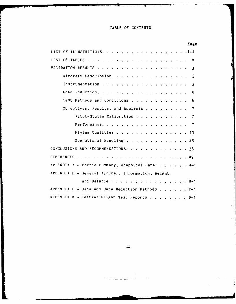
TABLE OF CONTENTS
Page
LIST OF ILLUSTRATIONS...................iii
LIST OF TABLES.......................v
VALIDATION RESULTS.....................3
Aircraft Description..................3
Instrumentation...................3
Data Reduction.....................6
Test Methods and Conditions..............6
Objectives, Results, and Analysis .......... 7
Pitot-Static Calibration.............7
Performance...................7
Flying Qualities................13
Operational Handling..............23
CONCLUSIONS AND RECOMMENDATIONS. ............. 38
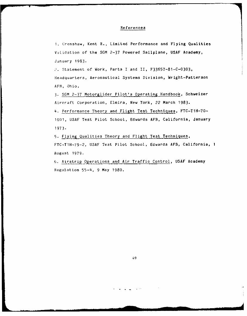
REFERENCES........................49
APPENDIX A - Sortie Summary, Graphical Data. ........ A-1
APPENDIX B - General Aircraft Information, Weight
and Balance.................B-1
APPENDIX C - Data and Data Reduction Methods ........ C-1
APPENDIX D - Initial Flight Test Reports..........D-1
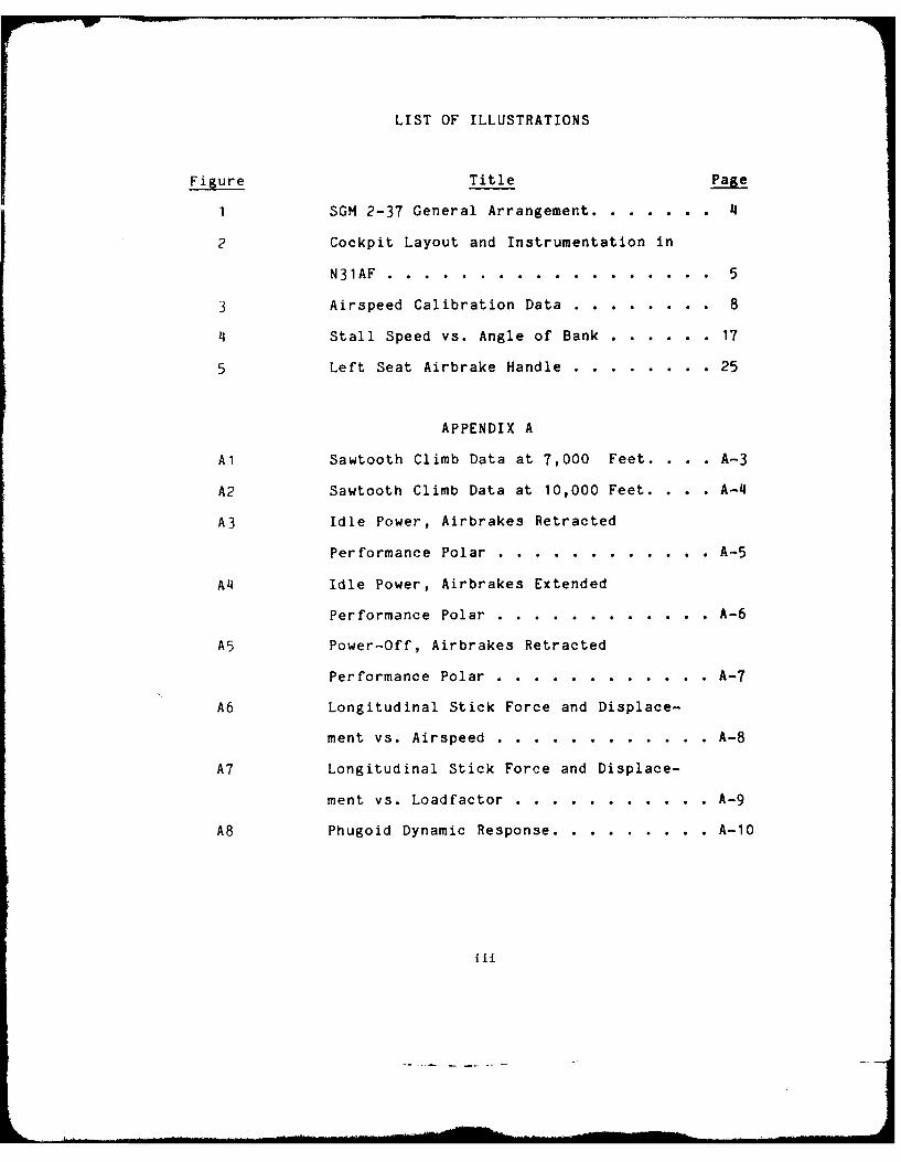
LIST OF ILLUSTRATIONS
Figure Title Page
1 SGM 2-37 General Arrangement ........... 4
2 Cockpit Layout and Instrumentation in
N31AF ......... .................. 5
3 Airspeed Calibration Data .... ........ 8
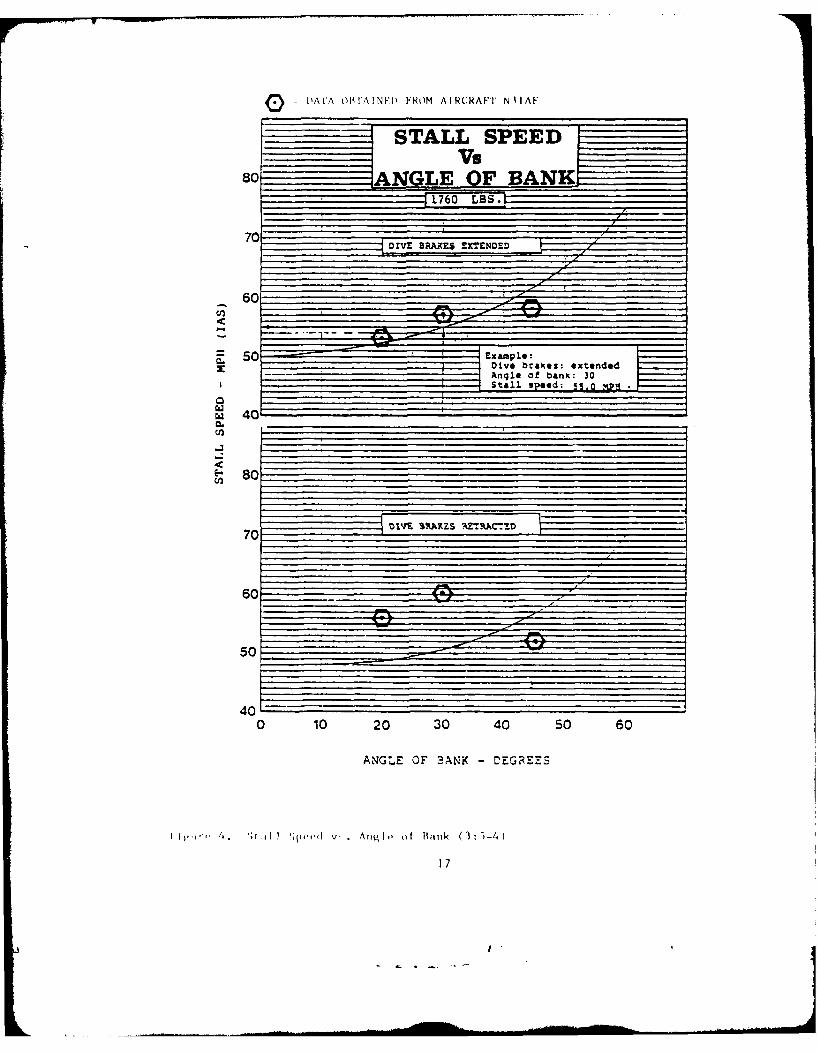
4 Stall Speed vs. Angle of Bank ........ .. 17
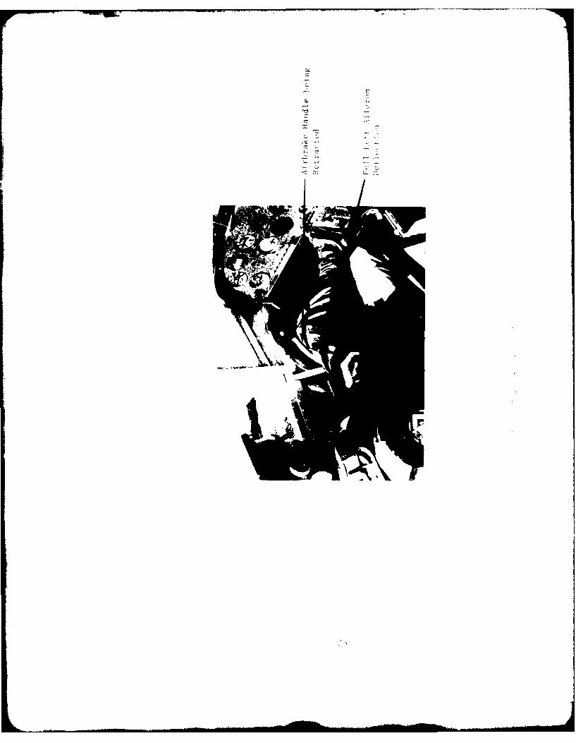
5 Left Seat Airbrake Handle ........... .25
APPENDIX A
Al Sawtooth Climb Data at 7,000 Feet. . .. A-3
A2 Sawtooth Climb Data at 10,000 Feet. . .. A-4
A3 Idle Power, Airbrakes Retracted
Performance Polar .... ............ .A-5
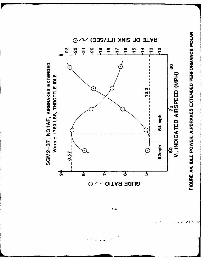
A4 Idle Power, Airbrakes Extended
Performance Polar .... ............ .A-6
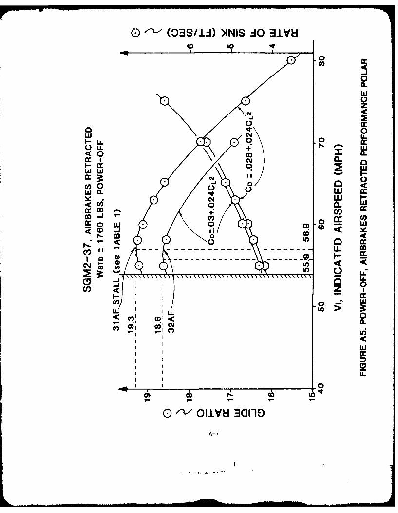
A5 Power-Off, Airbrakes Retracted
Performance Polar .... ............ .A-7
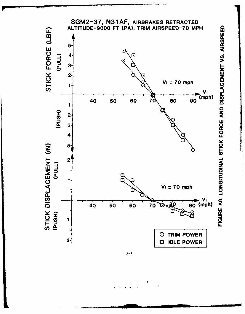
A6 Longitudinal Stick Force and Displace-
ment vs. Airspeed .... ............ .A-8
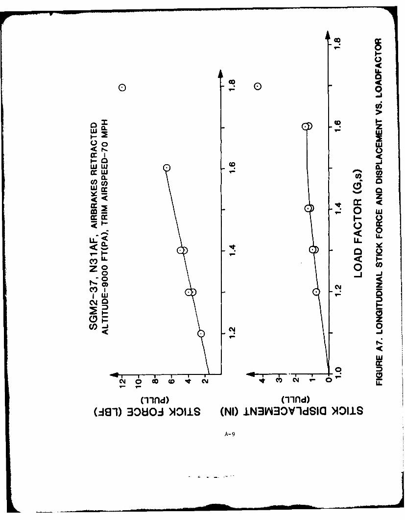
A7 Longitudinal Stick Force and Displace-
ment vs. Loadfactor ... ........... .. A-9
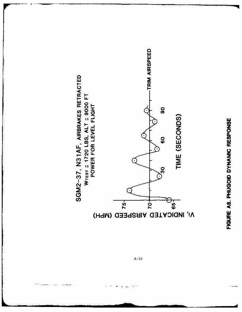
A8 Phugoid Dynamic Response ........... .. A-10
ii
LIST OF ILLUSTRATIONS CCONT'D)
Figr Title Page
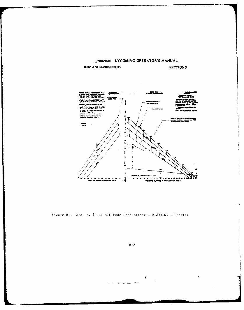
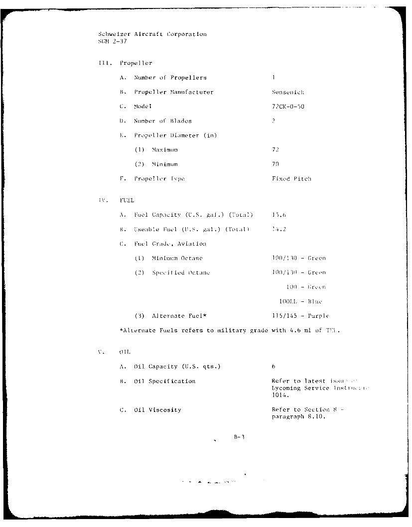
B1 Sea Level and Altitude Performance
0-235-K, -L Series ............. B-2
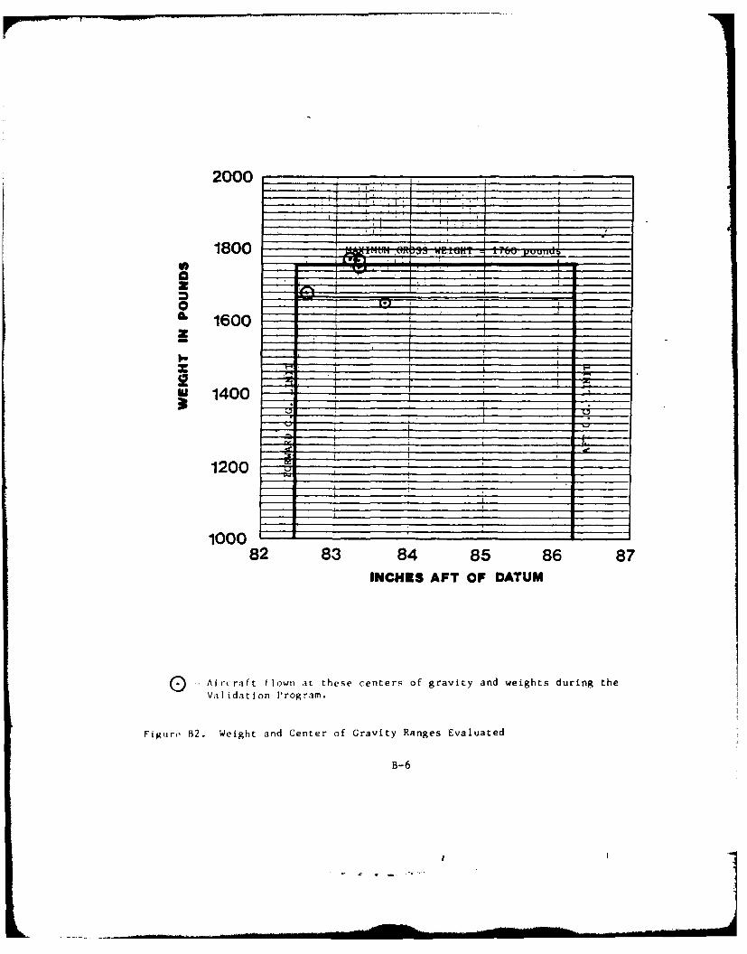
B2 Weight and Center of Gravity Ranges
Evaluated.................B-6
iv
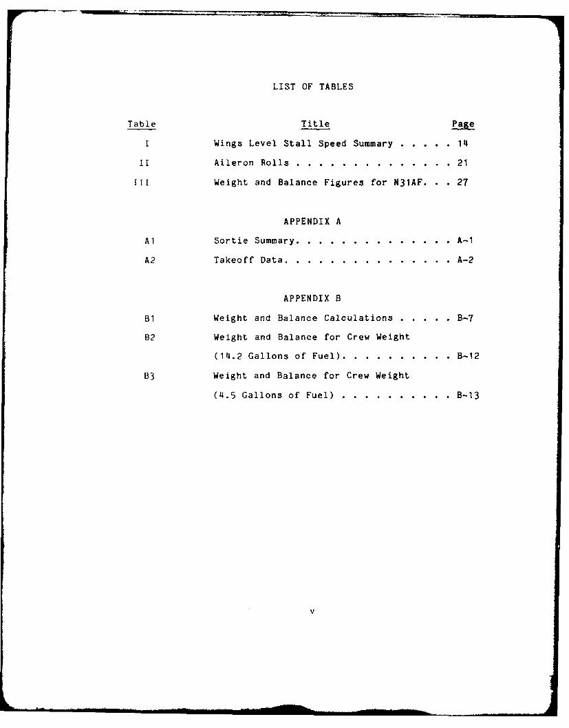
LIST OF TABLES
Table Title Page
I Wings Level Stall Speed Summary ...... .. 14
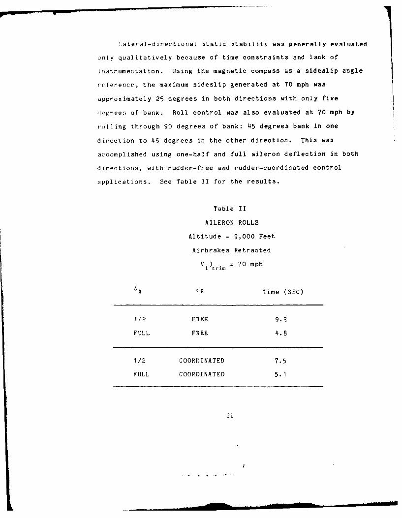
II Aileron Rolls ..... .............. .21
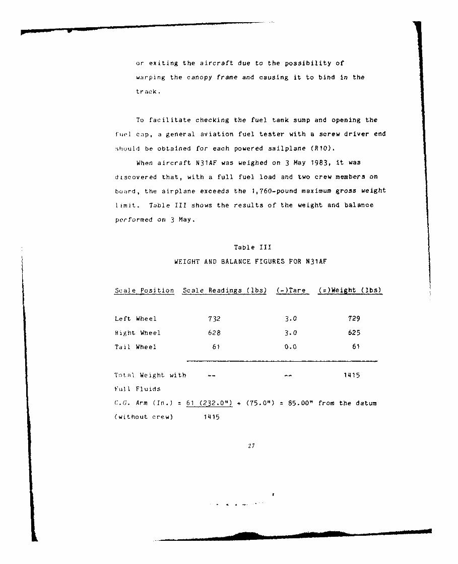
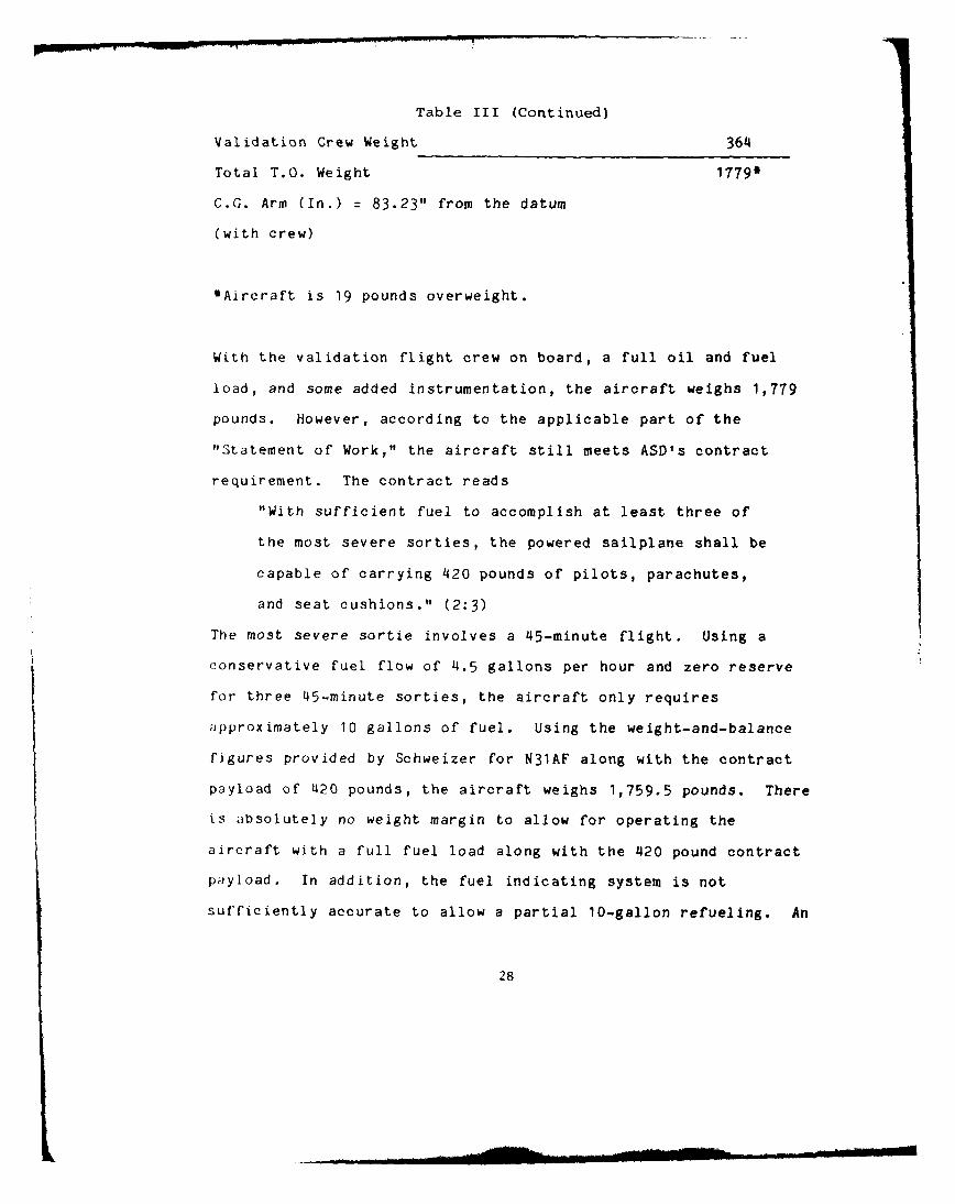
III Weight and Balance Figures for N31AF. . . 27
APPENDIX A
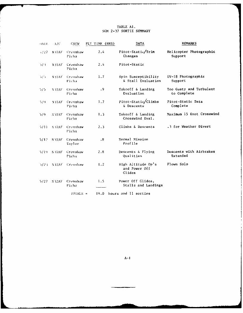
Al Sortie Summary ..... .............. .A-I
A2 Takeoff Data ...... ............... .A-2
APPENDIX B
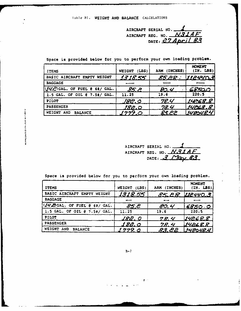
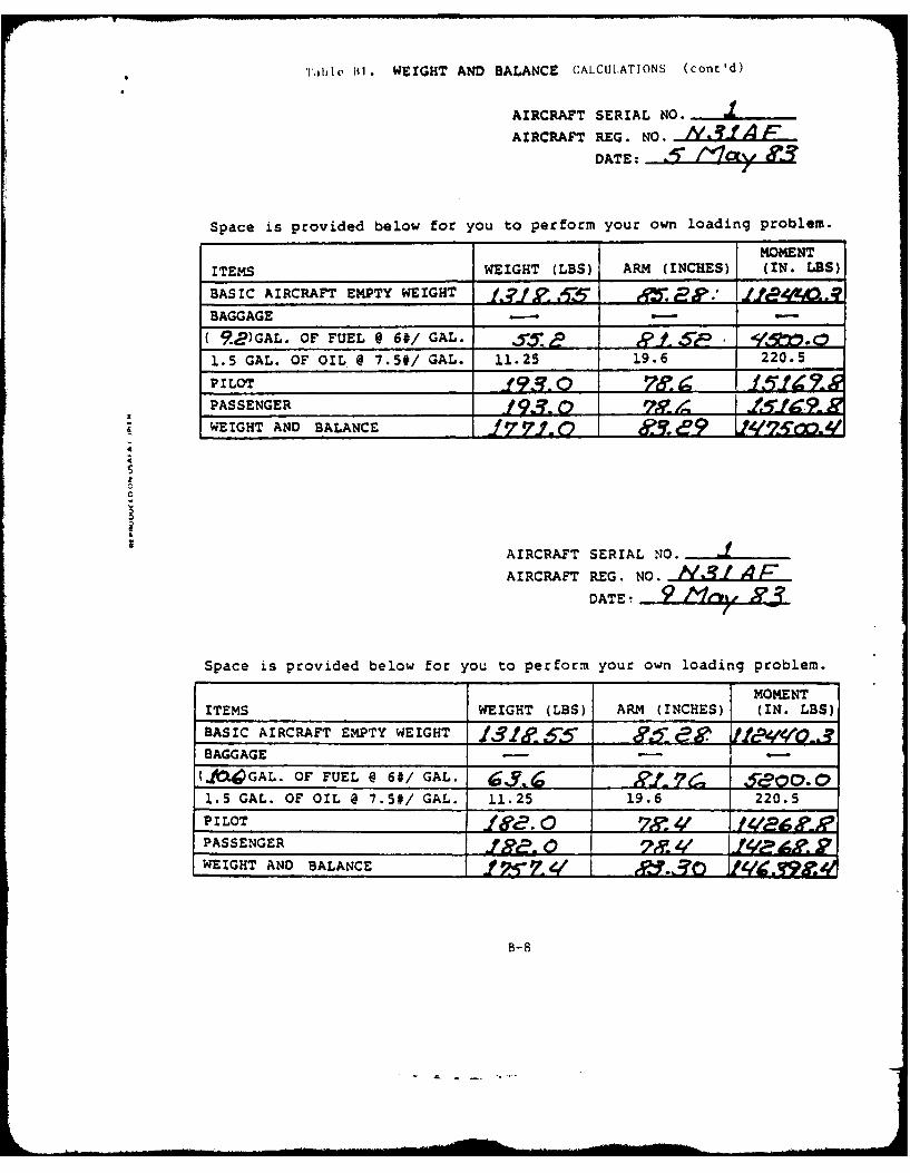
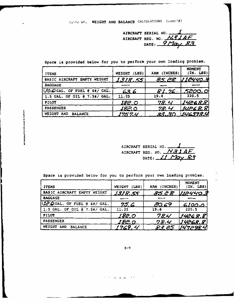
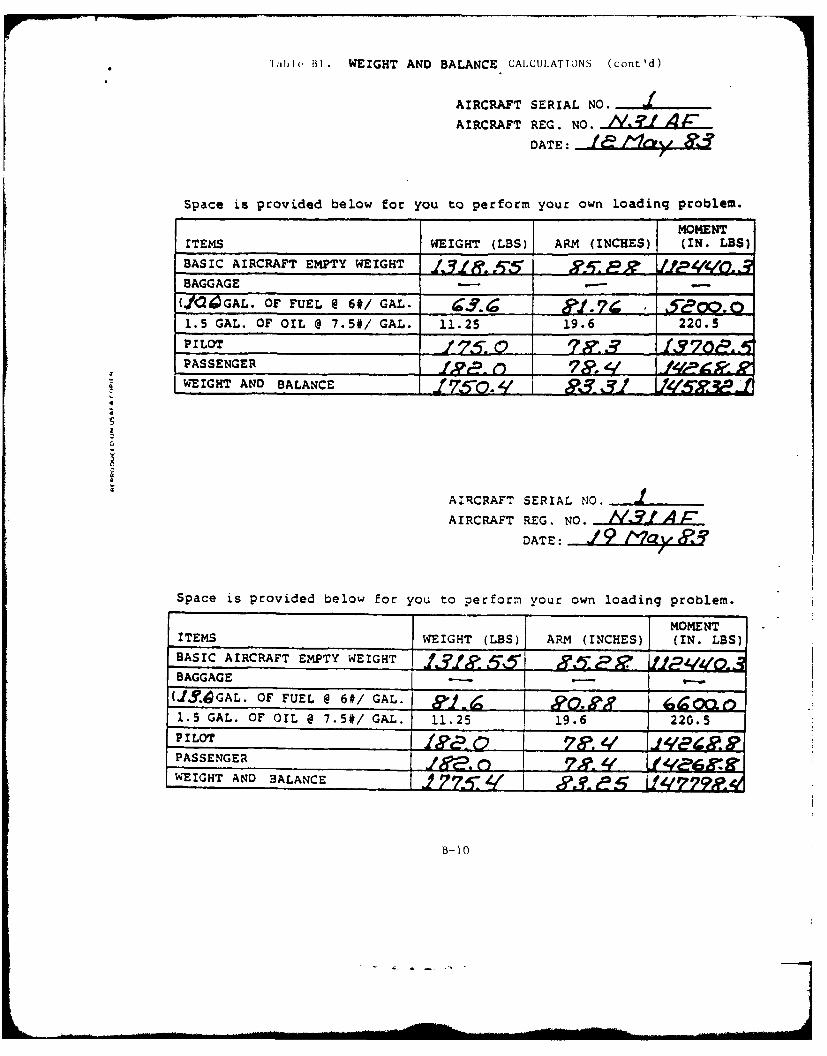
BI Weight and Balance Calculations ...... .B-7
B2 Weight and Balance for Crew Weight
(14.2 Gallons of Fuel) .... .......... .B-12
B3 Weight and Balance for Crew Weight
(4.5 Gallons of Fuel) ... .......... B-13
VI
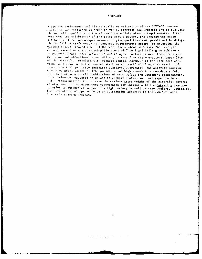
ABSTRACT
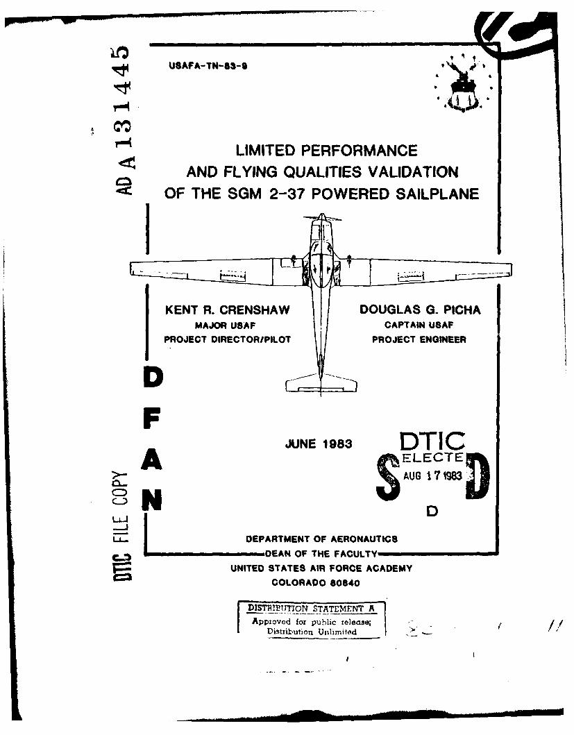
A i',.,l performance and flying qualities validation of the SGM2-37 powereda..,J;.I.e wais conducted in order to verify contract requirements and to evaluate
ri w. )vvrall tapability of the aircraft to satisfy mission requirements. Aftervrilvi, g the calibration of the pitot-static system, the program was accom-plilod in three ohases-performance, flying qualities and operational handling.lI .S;M')-37 aircraft meets all contract requirements except for exceeding themaxinn rakeoff ground run of 1000 feet; the minimum sink rate 240 feet perrillire . exceeding the approach glide slope of 7 to 1 and failing to achieve a
wik., level stall speed between 35 and 45 mph. Failure to meet these require-rn,Yirs was not objectionable and Jid not detract from the operational caoabilityif th, iaircrafr. Problems with cockpit control movement of the left seat air-lr.ik,.. hlrodle and with the control stick were identified along with eratic andil,,irur;te ftuel quanitity indicator displays., <Currently, the aircraft maximumerr ilied grss ,eight of 1760 pounds is not hi'gh enough to accomodate a full
Iutel load along with all combinations of crew weC1t and equipment requirements.In, addition to suggested solutions to cockpit controll and fuel gage problems,.Id a recommendation re increase the maximum gross weight of the aircraft, severalwarning ind caution notes were recommended for inclusion in the Operating Handbookin order to enhance ground and in-flight safety as well as crew comfort. Generally,rh aircraft should prove to be an outstanding addition to the U.S.Air ForceAcademy's Soaring Program.
vi
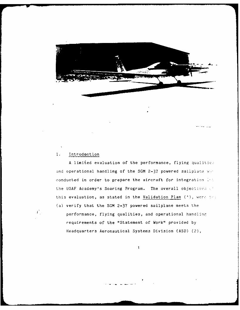
I. Introduction
A limited evaluation of the performance, flying qualitie-
and operational handling of the SGM 2-37 powered sailplane we
conducted in order to prepare the aircraft for integration
the USAF Academy's Soaring Program. The overall objective:;
this evaluation, as stated in the Validation Plan (1), werc
(a) verify that the SGM 2-37 powered sailplane meets the
performance, flying qualities, and operational handling
requirements of the "Statement of Work" provided by
Headquarters Aeronautical Systems Division (ASD) (2),
.. . . ... . .. . . . " -- _ . .. .. fl I I I I I - .. . . .. . . .
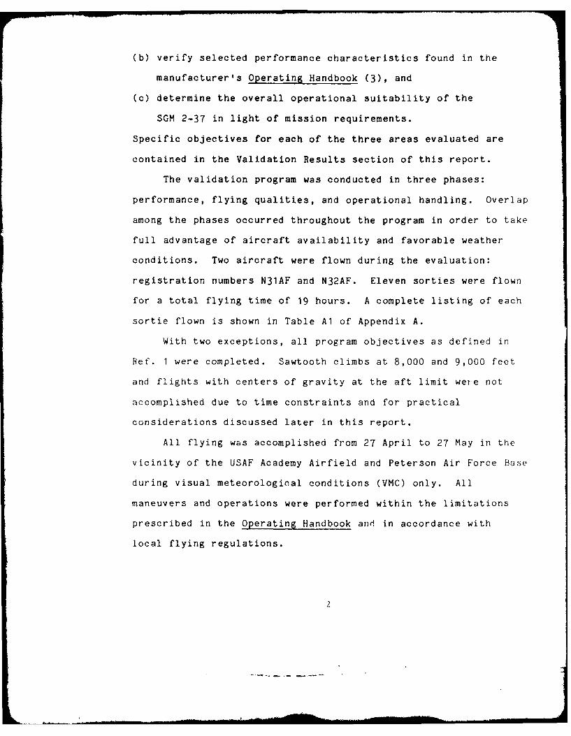
(b) verify selected performance characteristics found in the
manufacturer's Operating Handbook (3), and
(c) determine the overall operational suitability of the
SGM 2-37 in light of mission requirements.
Specific objectives for each of the three areas evaluated are
contained in the Validation Results section of this report.
The validation program was conducted in three phases:
performance, flying qualities, and operational handling. Overlap
among the phases occurred throughout the program in order to take
full advantage of aircraft availability and favorable weather
conditions. Two aircraft were flown during the evaluation:
registration numbers N31AF and N32AF. Eleven sorties were flown
for a total flying time of 19 hours. A complete listing of each
sortie flown is shown in Table Al of Appendix A.
With two exceptions, all program objectives as defined in
Ref. I were completed. Sawtooth climbs at 8,000 and 9,000 feet
and flights with centers of gravity at the aft limit were not
accomplished due to time constraints and for practical
considerations discussed later in this report.
All flying was accomplished from 27 April to 27 May in the
vicinity of the USAF Academy Airfield and Peterson Air Force Base
during visual meteorological conditions (VMC) only. All
maneuvers and operations were performed within the limitations
prescribed in the Operating Handbook and in accordance with
local flying regulations.
_ II li I l .. i I -2-
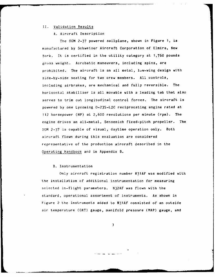
II. Validation Results
A. Aircraft Description
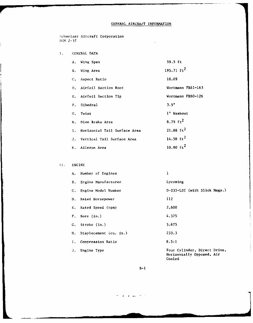
The SGM 2-37 powered sailplane, shown in Figure 1, is
manufactured by Schweizer Aircraft Corporation of Elmira, New
York. It is certified in the utility category at 1,760 pounds
gross weight. Acrobatic maneuvers, including spins, are
prohibited. The aircraft is an all metal, low-wing design with
side-by-side seating for two crew members. All controls,
including airbrakes, are mechanical and fully reversible. The
horizontal stabilizer is all movable with a leading tab that also
serves to trim out longitudinal control forces. The aircraft is
powered by one Lycoming 0-235-L2C reciprocating engine rated at
112 horsepower (HP) at 2,600 revolutions per minute (rpm). The
engine drives an all-metal, Sensenich fixed-pitch propeller. The
SGM 2-37 is capable of visual, daytime operation only. Both
aircraft flown during this evaluation are considered
representative of the production aircraft described in the
Operating Handbook and in Appendix B.
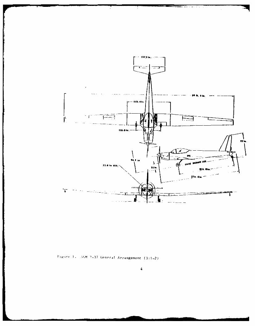
B. Instrumentation
Only aircraft registration number N31AF was modified with
the installation of additional instrumentation for measuring
selected in-flight parameters. N32AF was flown with the
standard, operational assortment of instruments. As shown in
Figure 2 the instruments added to N31AF consisted of an outside
air temperature (OAT) gauge, manifold pressure (MAP) gauge, and
3
- .... ____S__.-_..._-
I11.0 In .----- , \n1 -- 270.
lr+. 1. ,;(,I 2-57 (cGneratl Arrangement (3:1-2)
4
4 J
E
0
UC-)
-
C-.
U
CflC)U
~0
CCC
'2
C)~0
U o
C)CCOUC) C) -
C-C C)
C
5
accelerometer. A hand-held calibrated force gauge and a tape
measure were carried on selected flights in order to measure
control stick forces and displacements. A stopwatch was used to
measure climbs, descents, accelerations, and dynamic
characteristics, and for pitot-static calibration runs. A
cassette tape player was found to be particularly useful for
recording qualitative comments.
C. Data Reduction
All test data was reduced to standard atmospheric
conditions and a standard weight of 1,760 pounds using the
formats shown in Appendix C. Where required by Ref. 2, data was
extrapolated to 10,000 feet density altitude. Computer support
was provided by a programmable TI 58C calculator built by Texas
Instruments.
D. Test Methods and Conditions
Data sorties, summarized in Table Al, were flo ;L
accordance with the Validation Plan (1). While this ,
flight test program, commonly recognized and approved i-,-!t
techniques were used in order to validate the performn z, i
flying qualities of the SGM 2-37. Specific flight t.
techniques are discussed in the "Initial Flight Test Report:'
Appendix D and in Refs. 4 and 5. All flights were conducted
within the limitations stated in the Validation Plan (1:10),
6
the Operating Handbook (3:2-1 to 2-11) and in accordance with
USAFA Regulation 55-4 (6).
E. Objectives, Results, and Analysis
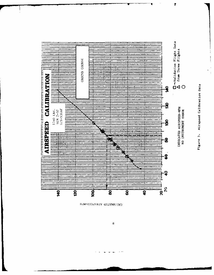
1. Pitot-Static Calibration
Pitot-static calibration runs were flown in order to:
(a) verify the airspeed calibration data presented in the
Operating Handbook (3:5-3) and
(b) investigate the effect of position error by flying with
airbrakes extended.
All objectives were achieved. The pitot-static system of the
aircraft was calibrated using a 1.7 statute mile ground course
north of the Academy on an east/west heading. The aircraft was
flown at 7,500 feet pressure altitude at selected airspeeds from
55 to 110 mph. Calibration runs were flown with airbrakes
retracted and with airbrakes extended. For both airbrake
configurations the position error for the pitot-static system was
found to be negligible. The airspeed calibration data, shown in
Figure 3, lies almost exactly along the calibration curve
supplied by the manufacturer. In addition, no measureable
difference in position error was found by flying the aircraft in
different airbrake configurations.
2. Performance
The objectives of the performance phase of the
validation program were to
7
Aj
A Ac
00
0w
E-4~ 04
N~ 0
* CL
1I*.Zi:. ....-.
0
-ao
.........
"'4 X
(a) verify the no-wind takeoff ground run from a dry, hard
surface at 10,000 feet density altitude as being 1,000 feet
or less (2:2),
(b) verify that the aircraft is capable of at least a 400 feet
per minute rate of climb at 10,000 feet density altitude
(2:2),
(c) verify that the idle-thrust glide ratio is at least 20 to 1
(2:3),
(d) verify the power-off performance polar in the Operating
Handbook (3:5-5),
(e) verify that the approach glide ratio in idle thrust with
airbrakes fully extended is not flatter than 7 to 1 flying at
1.3 times the stall speed (2:3), and
(f) verify that the idle-thrust, minimum-sink rate is not more
than 240 feet per minute (fpm).
Objectives (a) through (f) were accomplished; however, not all
the requirements of Ref. 2 were met.
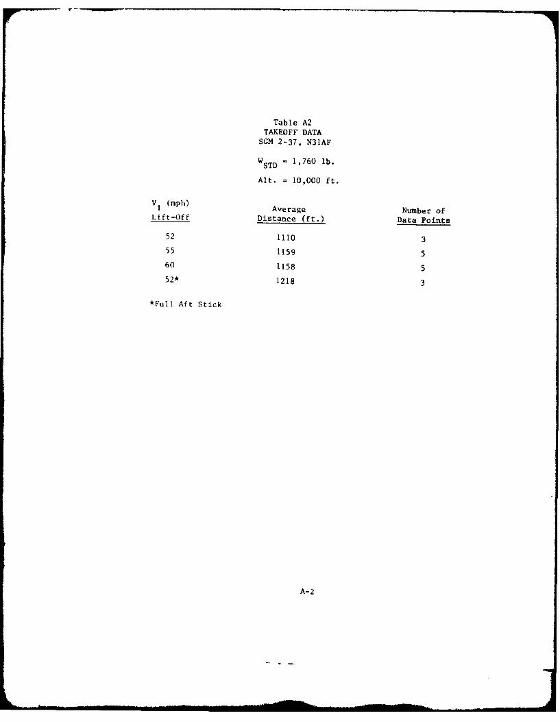
Takeoff ground run performance was evaluated at Peterson Air
Force Base and standardized to a maximum gross weight of 1,760
pounds and a density altitude of 10,000 feet. The validation
requirement is that the aircraft take off under no-wind
conditions at 10,000 feet density altitude from a dry, hard
surface in 1,000 feet of less (1:2). Using the takeoff technique
recommended by the Operating Handbook, the aircraft takeoff
ground run was found to be 1,110 feet. Other techniques, such as
higher takeoff speeds and full aft stick takeoffs, resulted in
9
higher ground runs. The aircraft does not satisfy the maximum
1,000 feet takeoff ground run requirement. See Table A2 for a
summary of takeoff data obtained.
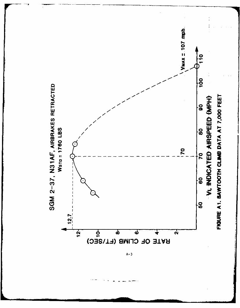
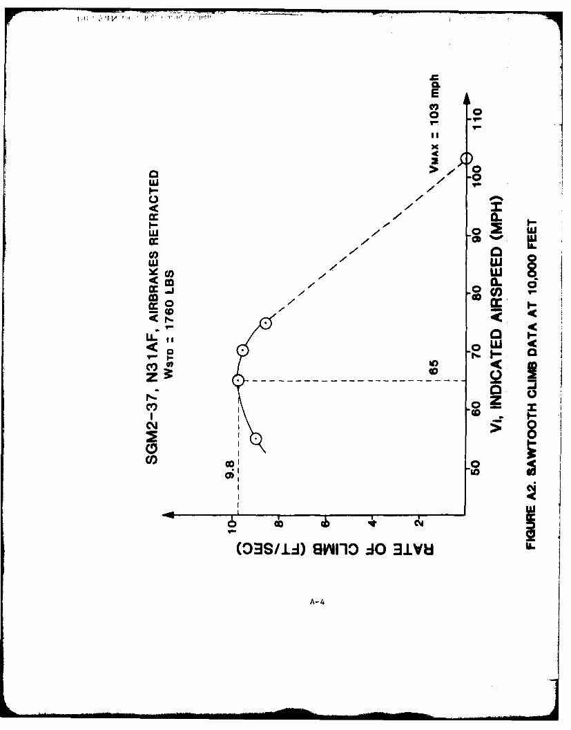
Climbs
Climb data was to be obtained at 7,000, 8,000, 9,000, and
10,000 feet pressure altitudes; however, due to time constraints,
data was obtained only at 7,000 and 10,000 feet pressure
altitudes. The validation requirement is that the aircraft
achieve a rate of climb of at least 400 feet per minute at 10,000
feet density altitude (2:2). Figures Al and A2 in Appendix A
show rates of climb data for 7,000 and 10,000 feet, respectively.
At 10,000 feet, with the data standardized to the maximum
certified gross weight of 1,760 pounds, the maximum rate of climb
is 588 feet per minute at an indicated airspeed of 70 miles per
hour (mph). At 7,000 feet the maximum rate of climb is nearly
800 fpm at 65 mph. Due to the narrow airspeed range between the
maximum rate of climb airspeed and the stall speed, insufficient
data was obtained to determine best angle of climb at either
altitude. While the aircraft meets the validation requirement
for rate of climb at 10,000 feet, the airspeed for maximum rate
of climb for both altitudes evaluated was between 65 and 70 mph.
The maximum rate of climb airspeed recommended in the Operating
Handbook (3:4-2) is 64 mph. Consideration should be given to
amending the Operating Handbook to indicate 68 mph for maximum
rate of climb (RI).
10
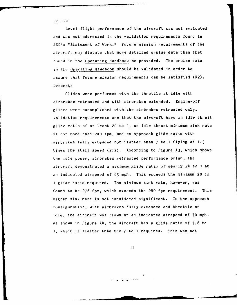
C r I II S
Level flight performance of the aircraft was not evaluated
and was not addressed in the validation requirements found in
ASD's "Statement of Work." Future mission requirements of the
aircraft may dictate that more detailed cruise data than that
found in the Operating Handbook be provided. The cruise data
in the Operating Handbook should be validated in order to
assure that future mission requirements can be satisfied (R2).
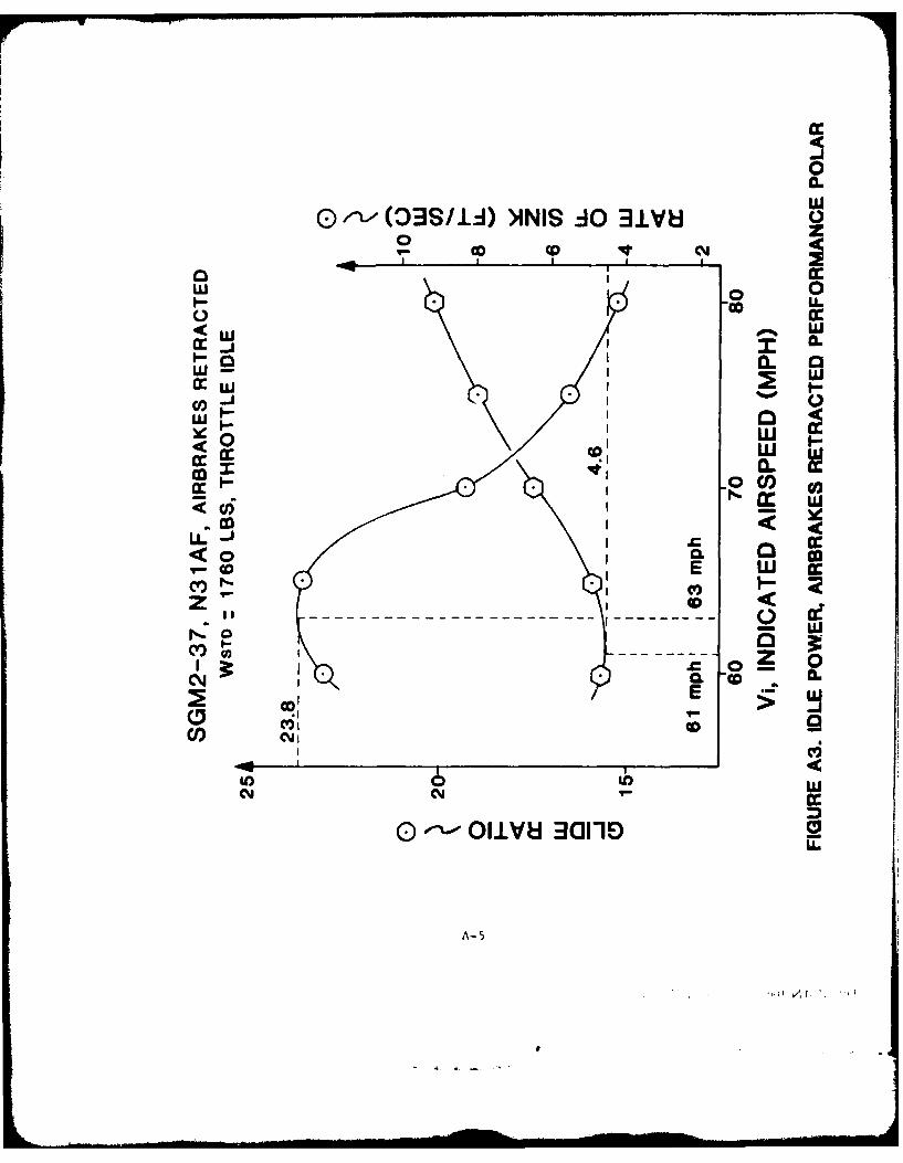
Descents
Glides were performed with the throttle at idle with
airbrakes retracted and with airbrakes extended. Engine-off
glides were accomplished with the airbrakes retracted only.
Validation requirements are that the aircraft have an idle thrust
glide ratio of at least 20 to 1, an idle thrust minimum sink rate
of not more than 240 fpm, and an approach glide ratio with
airbrakes fully extended not flatter than 7 to 1 flying at 1.3
times the stall speed (2:3). According to Figure A3, which shows
the idle power, airbrakes retracted performance polar, the
aircraft demonstrated a maximum glide ratio of nearly 24 to 1 at
an indicated airspeed of 63 mph. This exceeds the minimum 20 to
I glide ratio required. The minimum sink rate, however, was
found to be 276 fpm, which exceeds the 240 fpm requirement. This
higher sink rate is not considered significant. In the approach
configuration, with airbrakes fully extended and throttle at
idle, the aircraft was flown at an indicated airspeed of 70 mph.
As shown in Figure A4, the Aircraft has a glide ratio of 7.6 to
1, which is flatter than the 7 to 1 required. This was not
II
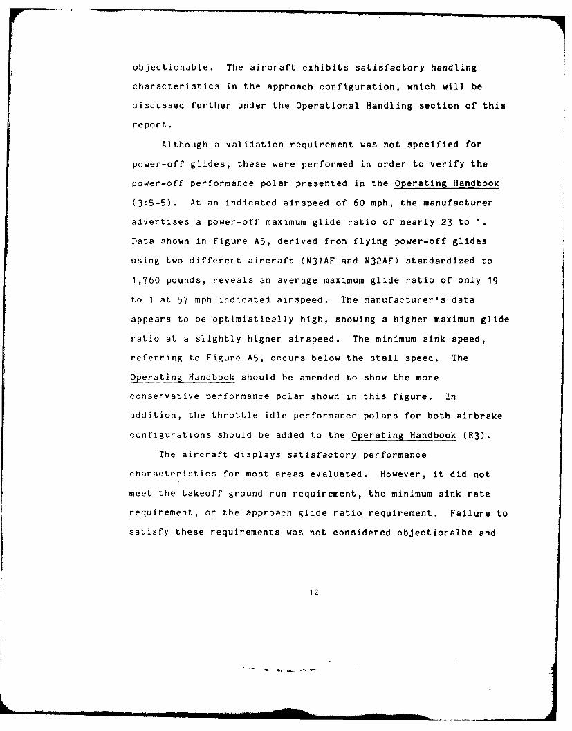
objectionable. The aircraft exhibits satisfactory handling
characteristics in the approach configuration, which will be
discussed further under the Operational Handling section of this
report.
Although a validation requirement was not specified for
power-off glides, these were performed in order to verify the
power-off performance polar presented in the Operating Handbook
(3:5-5). At an indicated airspeed of 60 mph, the manufacturer
advertises a power-off maximum glide ratio of nearly 23 to 1.
Data shown in Figure A5, derived from flying power-off glides
using two different aircraft (N31AF and N32AF) standardized to
1,760 pounds, reveals an average maximum glide ratio of only 19
to 1 at 57 mph indicated airspeed. The manufacturer's data
appears to be optimistically high, showing a higher maximum glide
ratio at a slightly higher airspeed. The minimum sink speed,
referring to Figure A5, occurs below the stall speed. The
Operating Handbook should be amended to show the more
conservative performance polar shown in this figure. In
addition, the throttle idle performance polars for both airbrake
configurations should be added to the Operating Handbook (R3).
The aircraft displays satisfactory performance
characteristics for most areas evaluated. However, it did not
meet the takeoff ground run requirement, the minimum sink rate
requirement, or the approach glide ratio requirement. Failure to
satisfy these requirements was not considered objectionalbe and
12
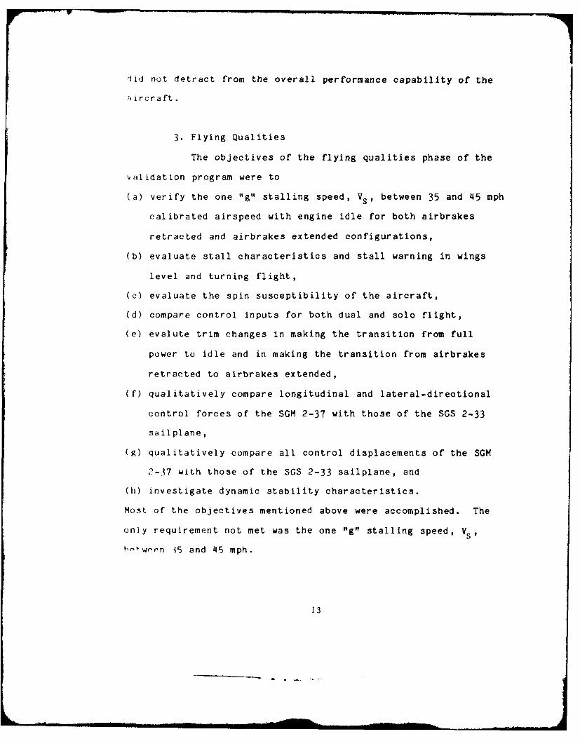
did not detract from the overall performance capability of the
:,irera ft.
3. Flying Qualities
The objectives of the flying qualities phase of the
validation program were to
(a) verify the one "g" stalling speed, Vs, between 35 and 45 mph
calibrated airspeed with engine idle for both airbrakes
retracted and airbrakes extended configurations,
(b) evaluate stall characteristics and stall warning in wings
level and turning flight,
(c) evaluate the spin susceptibility of the aircraft,
(d) compare control inputs for both dual and solo flight,
(e) evalute trim changes in making the transition from full
power to idle and in making the transition from airbrakes
retracted to airbrakes extended,
(f) qualitatively compare longitudinal and lateral-directional
control forces of the SGM 2-37 with those of the SGS 2-33
sailplane,
(g) qualitatively compare all control displacements of the SGM
1.5 GAL. OF OIL @ 7.5#/ GAL. 11.25 19.6 220.5PILOT -175. 0 qff. 3! 137&16.PASSENGER I LI.. . ,- P,
[WEIGHT AND BALANCE 0 ?, 31 L4'SR JC4
AIRCRAFT SERIAL NO. ,, .
AIRCRAFT PEG. NO. .DATE: ./9 s.;,y
Space is provided below for you to perform your own loading problem.
MOMENTITEMS WEIGHT (LBS) ARM (INCHES) (IN. LBS)BASIC AIRCRAFT EMPTY WEIGHT 9?- 9?5 f. i-wOuBAGGAGE --
d1S.4GAL. OF FUEL @ 6#/ GAL. el, 01.5 GAL. OF OIL @ 7.5#/ GAL. 11.25 19.6 220.5
PILOT
PASSENG ERWTEIGHT AND BALANCE .I 77. / . ,
B-TO
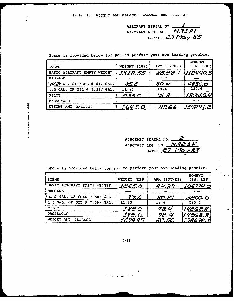
T ble Bi. WEIGHT AND BALANCE CALCULATIONS (cont'd)
AIRCRAFT SERIAL NO. J
AIRCRAFT REG. NO. Y ... J!LAFDATE: g.!? ey
Space is provided below for you to perform your own loading problem.
MOMENTITEMS WEIGHT (LBS) ARM (INCHES) (IN. LBS)
BASIC AIRCRAFT EMPTY WEIGHT 7-
BAGGAGE
(.l42c.-GAL. OF FUEL @ 6#/ GAL. a e&- g oO1.5 GAL. OF OIL @ 7.5#/ GAL. 11.25 19.6 220.5
PILOT l.&Tj3 0 700.1PASSENGER -I -
WEIGHT AND BALANCE agir, 0 e, LT77--
AIRCRAFT SERIAL NO.AIRCRAFT REG. NO. )V',9? A F
DATE: a7 m I 9Jf
Space is provided below for you to perform your own loading problem.
MOMENTITEMS WEIGHT (LBS) ARM (INCHES) (IN. LBS)
BASIC AIRCRAFT EMPTY WEIGHT 0" ,7BAGGAGE - - -
(6. )GAL. OF FUEL @ 6#/ GAL. 9. ,1.5 GAL. OF OIL @ 7.5#/ GAL. 11.25 19.6 220.5
PILOT
WEIGHT AND BALANCE .f .. " ,
B-11
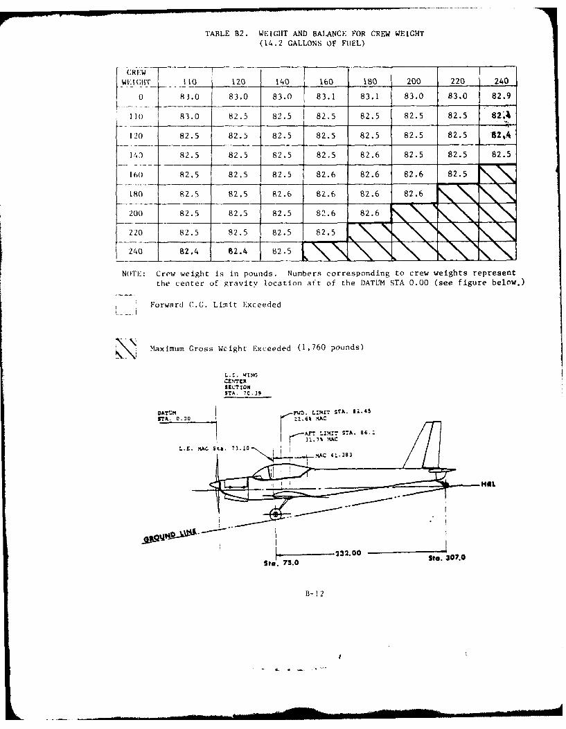
TABLE B2. WEIGHT AND BALANCE FOR CREW WEIGHT(14.2 GALLONS OF FUEL)
10C1lf Ii 120 140 160 180 200 220 240
0 83.0 83.0 83.0 83.1 83.1 83.0 83.0 82.9
110 I 83.0 82.5 82.5 82.5 82.5 82.5 82.5 82A~
120 82.5 82.5 82.5 82.5 82.5 82.5 82.5 62A.
141) 82.5 82.5 82.5 82.5 82.6 82.5 82.5 82.5
160 82.5 82.5 82.5 82.6 82.6 82.6 82.5
180 92.S 82.5 82.6 82.6 82.6 82.6 N
200 82.5 82.5 82.5 82.6 82.6
2 20 82.5 82.5 82.5 82.5
240 92.4 62.4 82.5
NOTE-: Crew weight is in pounds. Numbers corresponding to crew weights represent
the center of gravitv location aft of the DATUM STA 0.00 (see figure below.)
Forward C.G. Limit Exceeded
Maximum Gross Weight Exceeded (1,760 pounds)
L.E. WING
SECT IONSTA. 70.39
STA.~- 32 000z.6 A
St.. 75.0 Ste. 307.0
B- 12
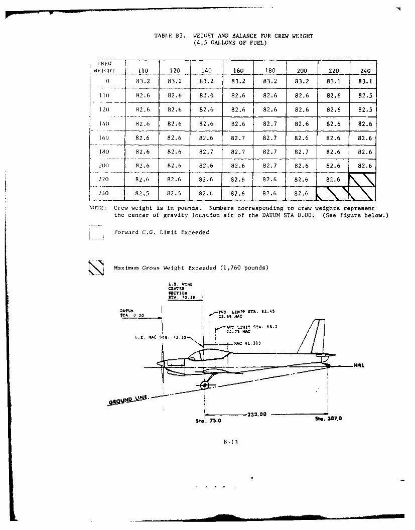
TABLE B3. WEIGHT AND BALANCE FOR CREW WEIGHT(4.5 GALLONS OF FUEL)
CR EWWICHIT 110 120 140 160 180 200 220 240
01 83.2 83.2 83.2 83.2 83.2 83.2 83.1 83.1
1101 82.6 82.6 82.6 82.6 82.6 82.6 82.6 82.5
120) 82.6 82.6 82.6 82.6 82.6 82.6 82.6 82.5
140 82.6 82.6 82.6 82.6 82.7 82.6 82.6 82.6
160 82.6 82.6 82.6 82.7 82.7 82.6 182.6 182.6
180 82.6 82.6 82.7 82.7 82.7 82.7 82.6 82.6
200 82.6 82.6 82.6 82.6 82.7 82.6 82.6 82.6
220) 82.6 82.6 82.6 82.6 82.6 82.6 82. 6
240 82.5 82.5 82.6 82.6 82.6 82.6
NOTE: Crew weight is in pounds. Numbers corresponding to crew weights representthe center of gravity location aft of the DATUM STA 0.00. (See figure below.)
VII. JDynamic Characteristics............................c-7
DATA AND DATA REDUCTION METHODS
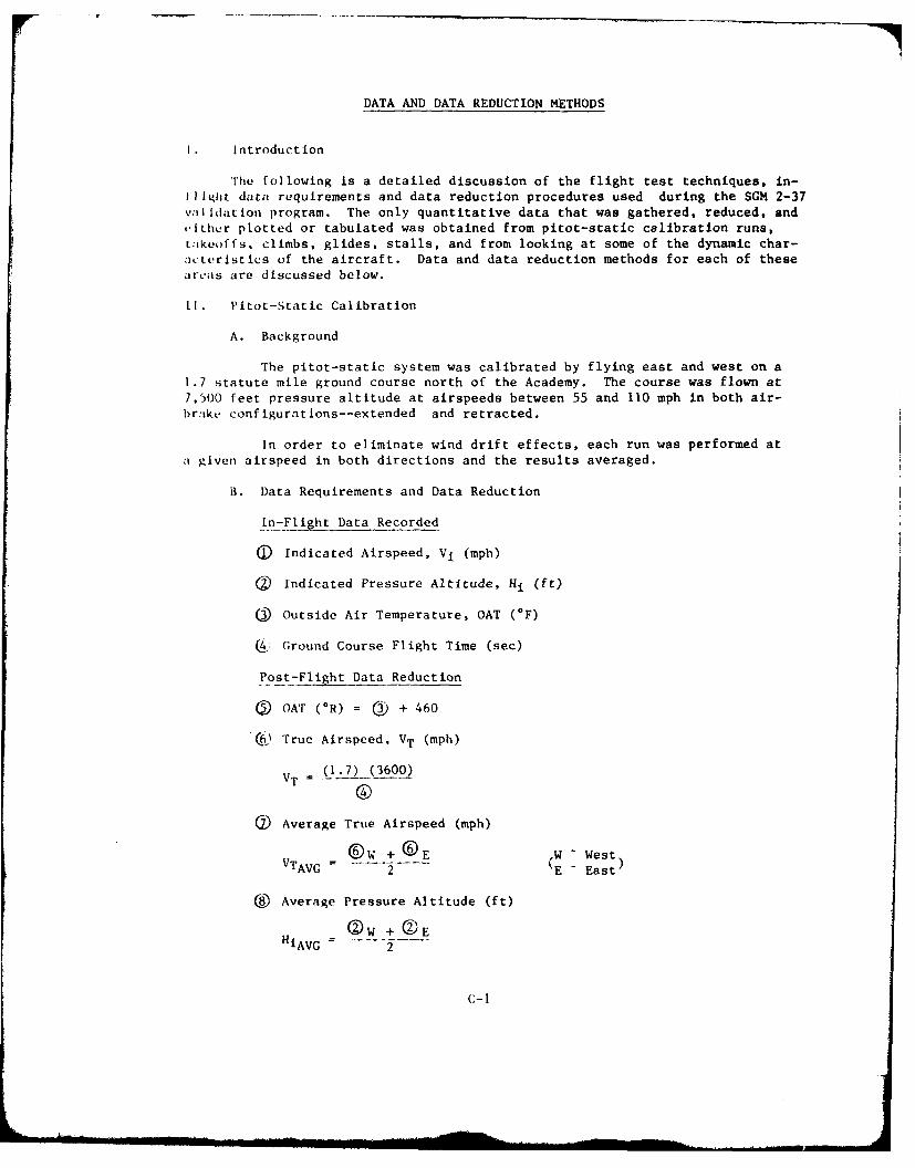
1. Introduction
'he following is a detailed discussion of the flight test techniques, in-
11Ight data requirements and data reduction procedures used during the SGM 2-37valIdation program. The only quantitative data that was gathered, reduced, andilther plotted or tabulated was obtained from pitot-static calibration runs,
takeoffs, climbs, glides, stalls, and from looking at some of the dynamic char-a'teristics of the aircraft. Data and data reduction methods for each of theseareas are discussed below.
I]. Pitot-Static Calibration
A. Background
The pitot-static system was calibrated by flying east and west on a1.7 statute mile ground course north of the Academy. The course was flown at
7,500 feet pressure altitude at airspeeds between 55 and 110 mph in both air-
brake configurations--extended and retracted.
In order to eliminate wind drift effects, each run was performed ata given airspeed in both directions and the results averaged.
B. Data Requirements and Data Reduction
In-Flight Data Recorded
(D Indicated Airspeed, Vi (mph)
(2 Indicated Pressure Altitude, Hi (ft)
( Outside Air Temperature, OAT (OF)
(_4 Ground Course Flight Time (sec)
Post-Flight Data Reduction
( OAT (OR) = C3) + 460
C True Airspeed, VT (mph)
V (1.7) (3600)
() Average True Airspeed (mph)
®w + ®E ,W - WestVTAVG .. 2 .E East
() Average Pressure Altitude (ft)
QW + 0EiAVG = 2
C- I
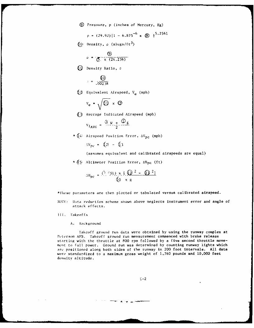
@ Pressure, p (inches of Mercury, Hg)
p = (29.92)[1 - 6.875- 6 x 5.2561
ui Density, p (slugs/ft3)
=-P x (24.236)
Density Ratio, o
0 .0b0239
6 Equivalent Airspeed, Ve (mph)
Ve =XG
(0 Average Indicated Airspeed (mph)
SW + EViAVG 2
* 64) Airspeed Position Error, AVpc (mph)
AV PC = C2)- I
(assumes equivalent and calibrated airspeeds are equal)
* Altimeter Position Error, LHpc (ft)
(lp oS L) x (a 0 2
*These parameters are then plotted or tabulated versus calibrated airspeed.
NOTE: Data reduction scheme shown above neglects instrument error and angle of
attack effects.
m11. Takeoffs
A. Background
Takeoff ground run data were obtained by using the runway complex atPeterson AFB. Takeoff ground run measurement commenced with brake release
starting with the throttle at 800 rpm followed by a five second throttle move-mcnt to full power. Ground run was determined by counting runway lights whicharc positioned along both sides of the runway in 200 foot intervals. All datawere standardized to a maximum gross weight of 1,760 pounds and 10,000 feetdensity altitude.
0-2
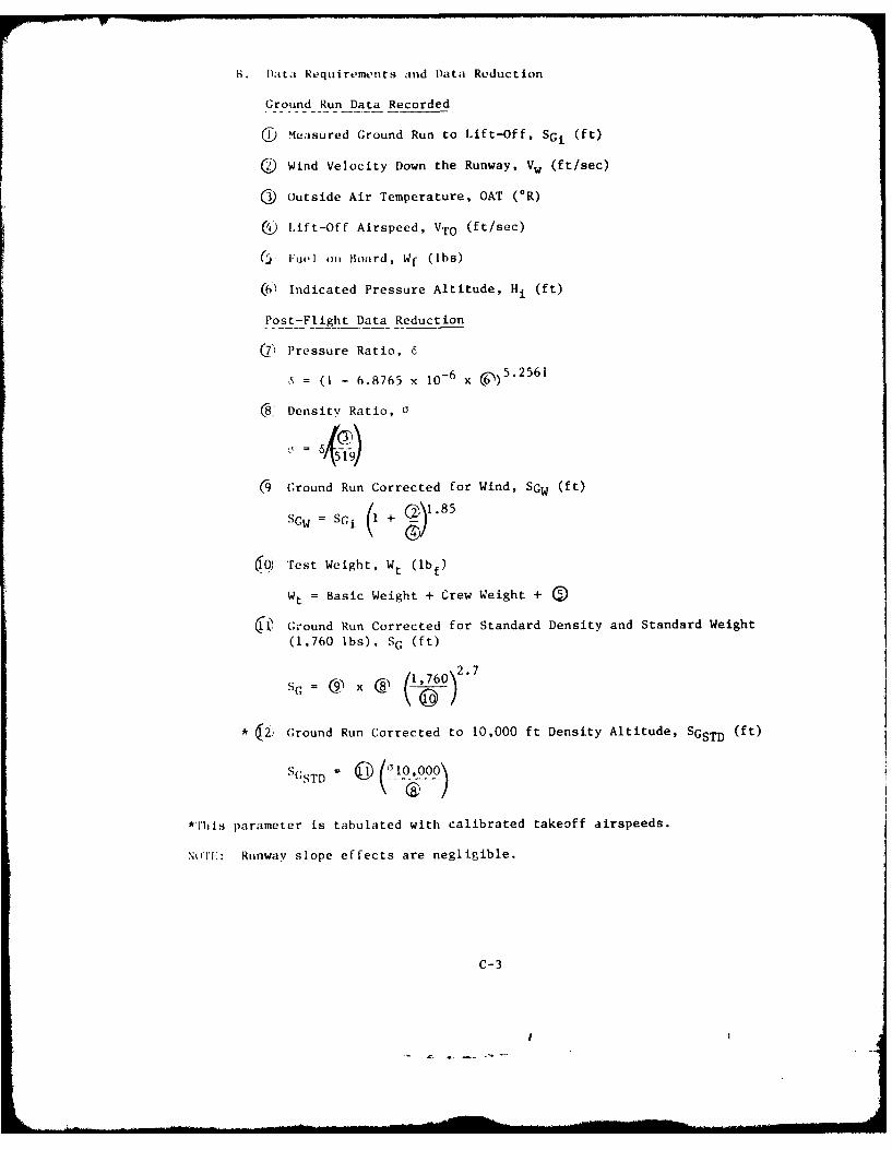
B. Data Requirements and Data Reduction
Ground Run Data Recorded
(1 Measured Ground Run to Lift-Off, SGi (ft)
O Wind Velocity Down the Runway, Vw (ft/sec)
Q Outside Air Temperature, OAT (*R)
(4) Lift-Off Airspeed, VTO (ft/sec)
( Iuel on Board, Wf (lbs)
( , Indicated Pressure Altitude, Hi (ft)
Post-Flight Data Reduction
(7 Pressure Ratio, 6
S = (I - 6.8765 x 10-6 x 6) 5.2561
® Density Ratio, 0
(9 Ground Run Corrected for Wind, SGw (ft)
SGW = Sci + o)1.85
Test Weight, Wt (lbf)
Wt = Basic Weight + Crew Weight +
( G Ground Run Corrected for Standard Density and Standard Weight
(1,760 Ibs), SG (ft)
S C = Cq C8 (1,7 6 0)
* 2) Ground Run Corrected to 10,000 ft Density Altitude, SGSTD (ft)
'S(;STD = J(j1IoMoo)
*This parameter is tabulated with calibrated takeoff airspeeds.
NoT1:: Runway slope effects are negligible.
C-3
LV. CLimbs
A. Background
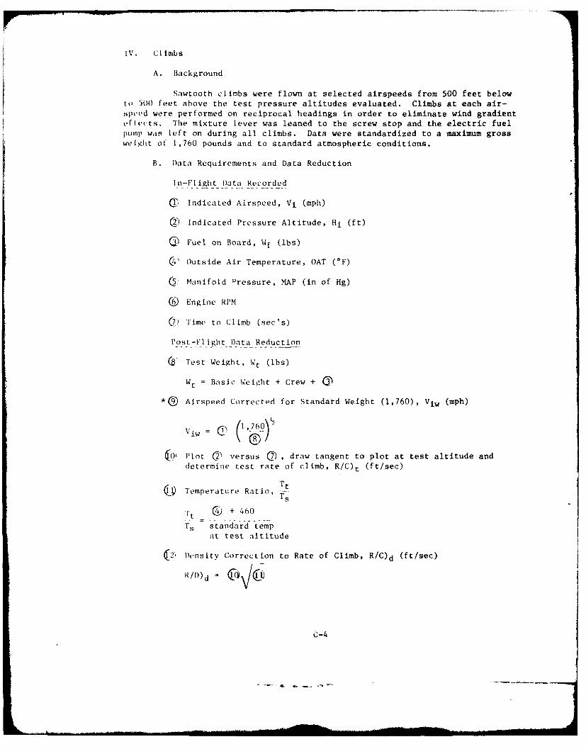
Sawtooth climbs were flown at selected airspeeds from 500 feet belowto 500 feet above the test pressure altitudes evaluated. Climbs at each air-s.peed were performed on reciprocal headings in order to eliminate wind gradientvfltuts. The mixture lever was leaned to the screw stop and the electric fuelpump was left on during all climbs. Data were standardized to a maximum grossweight of 1,760 pounds and to standard atmospheric conditions.
*0 Airspeed Corrected for Standard Weight (1,760), Viw (mph)
Viw = C' -760
Plot ) versus Q , draw tangent to plot at test altitude anddetermine test rate of climb, R/C)t (ft/sec)
6i Temperature Ratio, -j
Tt + 460
Ts standard tempat test altitude
2, Density Correction to Rate of Climb, R/C)d (ft/sec)
C-4
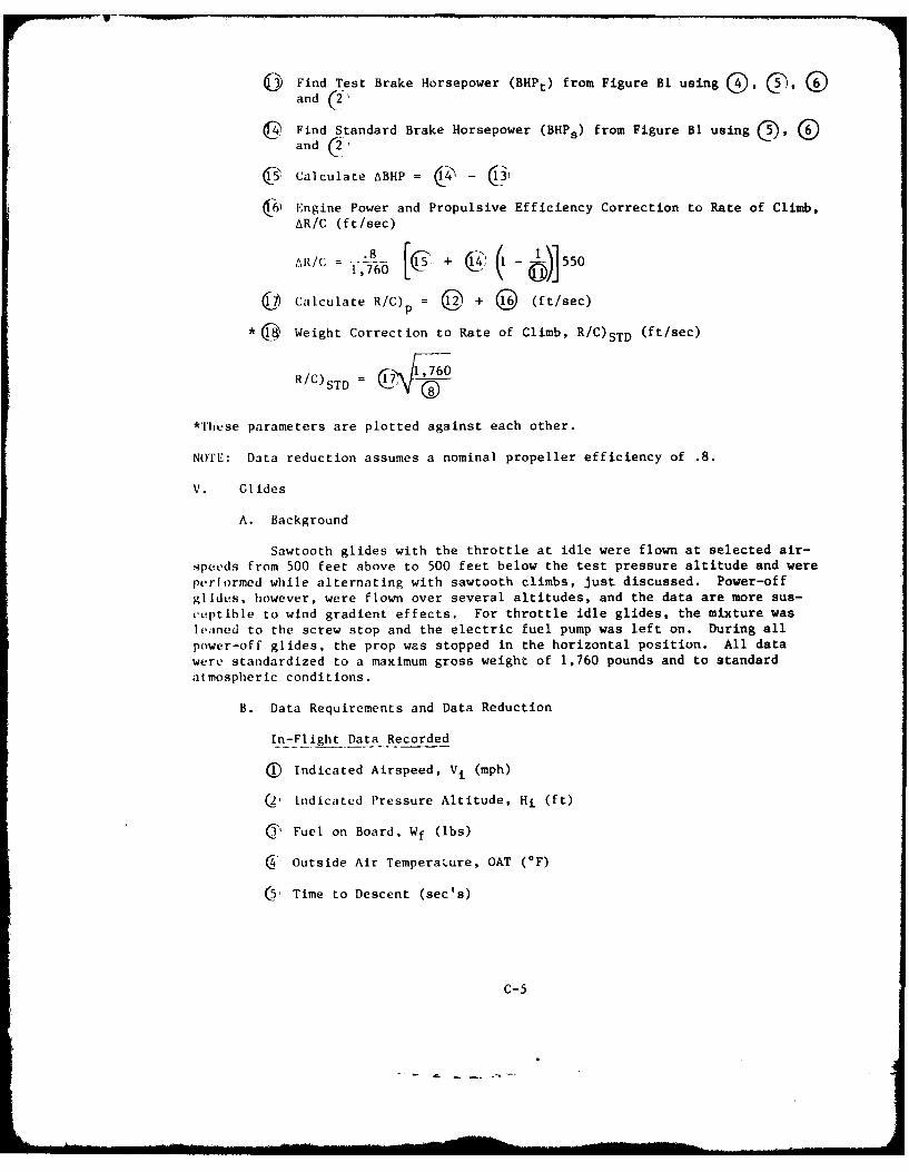
@3 Find Test Brake Horsepower CBHPt) from Figure BI using G. (, 5and (2"
@ Find Standard Brake Horsepower (BHPs) from Figure BI using 5, @and (2
63' Calculate ABHP = 4 - 3)
632 Engine Power and Propulsive Efficiency Correction to Rate of Climb,AR/C (ft/sec)
8= -+ 55-0
C" Calculate R/C)p = C + 3 (ft/sec)
*@ Weight Correction to Rate of Climb, R/C)sTD (ft/sec)
R/C) = 17A, 1 ,760STD kD
*These parameters are plotted against each other.
NOTE: Data reduction assumes a nominal propeller efficiency of .8.
V. Glides
A. Background
Sawtooth glides with the throttle at idle were flown at selected air-speeds from 500 feet above to 500 feet below the test pressure altitude and wereperformed while alternating with sawtooth climbs, just discussed. Power-offglides, however, were flown over several altitudes, and the data are more sus-ceptible to wind gradient effects. For throttle idle glides, the mixture wasleaned to the screw stop and the electric fuel pump was left on. During allpower-off glides, the prop was stopped in the horizontal position. All datawere standardized to a maximum gross weight of 1,760 pounds and to standardatmospheric conditions.
B. Data Requirements and Data Reduction
In-Flight Data Recorded
( Indicated Airspeed, Vi (mph)
Q Indicated Pressure Altitude, Hi (ft)
C3 Fuel on Board, Wf (Ibs)
4' Outside Air Tempera.ure, OAT (*F)
5, Time to Descent (sec's)
C-5
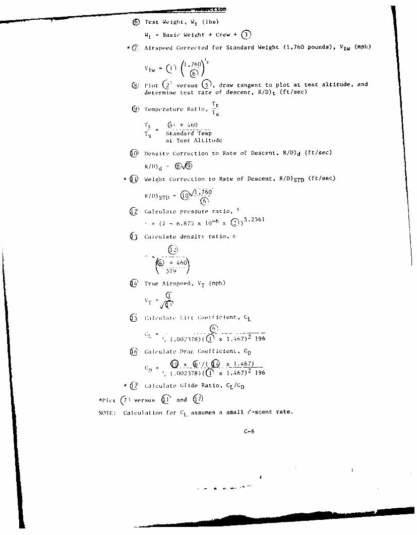
. Test Weight, Wt (ibs)
Wt = Basic Weight + Crew + )*Cj' Airspeed Corrected for Standard Weight (1,760 pounds), Viw (mph)
vtw c - ',o )
® Plot (h versus 5), draw tangent to plot at test altitude, and
determine test rate of descent, R/D)t (ft/sec)
() Temperature Ratio, st
Tt (C4 + 460
I'S Standard Tempat Test Altitude
Density Correction to Rate of Descent, R/D)d (ft/sec)
R/D)d=
* 6 Weight Correction to Rate of Descent, R/D)STD (ft/see)
R/t))S'l'D = 10 -- 7
QZ Calculate pressure ratio,
(I - 6.875 x 10- 6 x 0)
5.2561
6J Calculate density ratio,
\ "51-9 " /
C True Airspeed, VT (mph)
6 (%jIlci t ' I. ,itt Coefficient, CL
CI, (.00237-8)(D C x 1.467)2 196
(C' Calculate Drag: Coefficient, CD
C 0 Q x 1.467)
' (.002378)(QC x 1.467) 2 196
* _ (Calculate (lide Ratio, CL/CD
*,Plt (7) versus C and )
NOT: Calculation for Cl assumes a small eiscent rate.
C-6
S.-
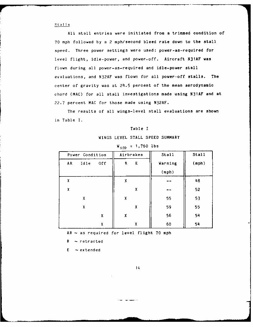
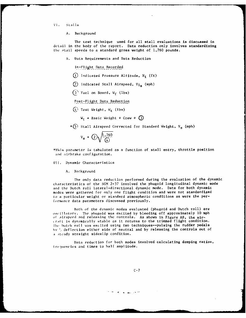
VI. Stalls
A. Background
The test technique used for all stall evaluations is discussed indetail in the body of the report. Data reduction only involves standardizing
the S tall speeds to a standard gross weight of 1,760 pounds.
B. Data Requirements and Data Reduction
In-Fliht Data Recorded
Q Indicated Pressure Altitude, Hi (ft)
Indicated Stall Airspeed, Vis (mph)
3 Fuel on Board, Wf (lbs)
Post-Flight Data Reduction
C Test Weight, Wt (lbs)
Wt = Basic Weight + Crew +
*C5 Stall Airspeed Corrected for Standard Weight, Vs (mph)
V 1,760
C40*This parameter is tabulated as a function of stall entry, throttle position
and ailrbrake configuration.
VII. Dynamic Characteristics
A. Background
The only data reduction performed during the evaluation of the dynamic
characteristics of the SGM 2-37 involved the phugoid longitudinal dynamic mode
and the Dutch roll lateral-directional dynamic mode. Data for both dynlamic
modes were gathered for only one flight condition and were not standardized
to a particular weight or standard atmospheric conditions as were the per-
formance data parameters discussed previously.
Both of the dynamic modes evaluated (phugoid and Dutch roll) are
os.illatorv. The phugoid was excited by bleeding off approximately 10 mphof airspeed and releasing the controls. As shown in Figure AS, the air-
r alt is dynamically stable as it returns to the trimmed flight condition.
lihi, Dutch roll was excited using two techniques--pulsing the rudder pedals
by '.. deflection either side of neutral and by releasing the controls out of
:a :-;teady straight sideslip condition.
Data reduction for both modes involved calculating damping ratios,
IrejlLencies and times to half amplitude.
c-7
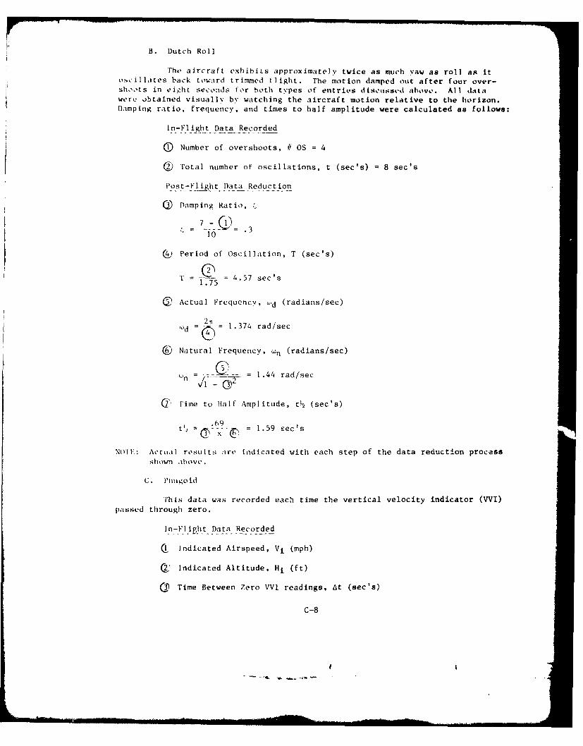
B. Dutch Roll
The aircraft exhibits approximately twice as much yaw as roll as itoscillates back toward trimmed flight. The motion damped out after four over-shoots in eight seconds for both types of entries discussed above. Al I datawere obtained visuall%" by watching the aircraft motion relative to the horizon.Damping ratio, frequency, and times to half amplitude were calculated as follows:
In-Flight Data Recorded
(D Number of overshoots, I OS = 4
2J Total number of oscillations, t (sec's) = 8 sec's
Post-Flight Data Reduction
@ Damping Ratio,
10
CO Period of Oscillation, T (sec's)
T = .-75 = 4.57 sec's1.75
® Actual Frequency, L'd (radians/sec)
10d .2 1.374 rad/sec
6 Natural Frequency, n (radians/sec)
. ... ... . 1.44 rad/sec
T Time to wnalf Amplitude, ta (se's)
.C-9
t2 69- = 1.59 ec's
NO'l V.: Actiial results airv indicated with each step of the data reduction process
C . P11,,kgo i(]
This data was recorded each time the vertical velocity indicator (WlI)
paIsse'd through zero.
In-Flilh. Date_ .Recorded
CIIndicated Airspeed, Vi (mph)
C2' Indicated Altitude, Hi (ft)
_3Time Between Zero VVI readings, At (sec's)
c-8
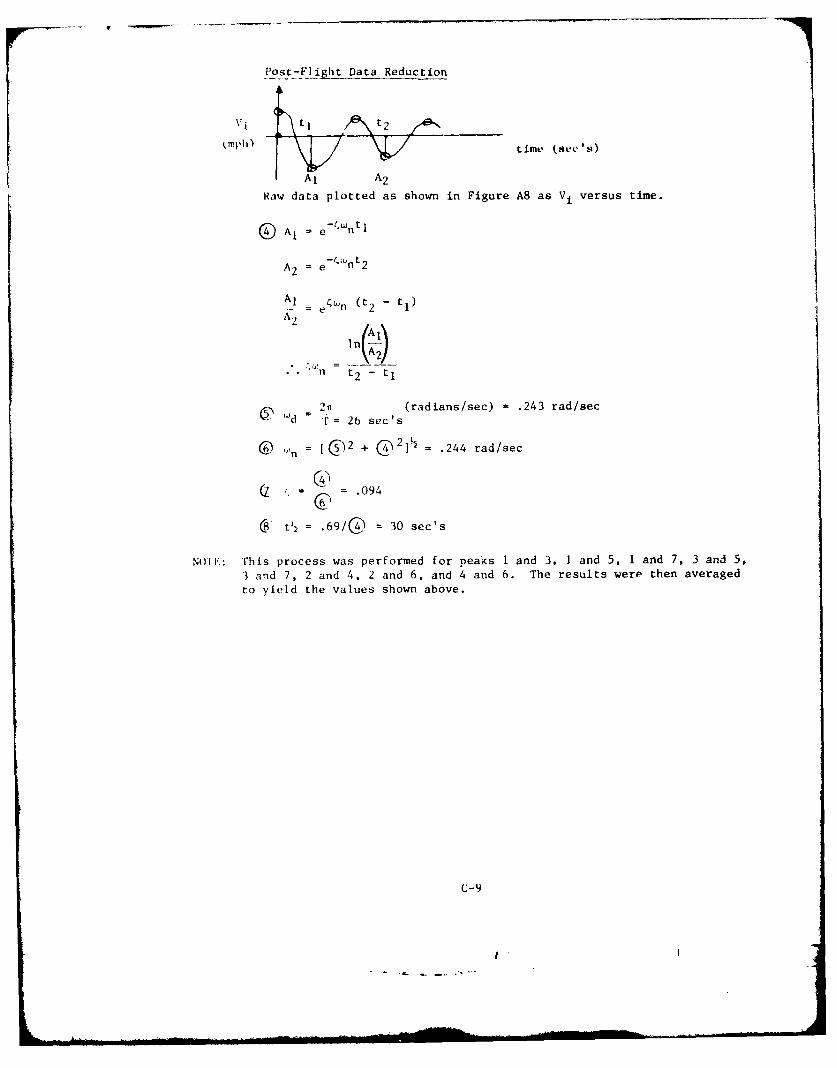
Post-Flight Data Reduction
(mph) time (SOC'sa)
Raw data plotted as shown in Figure A8 as V, versus time.
A, = e- ntl
A2 = e -(nt2
A1 - e4 wn (t2 - t1)
AA
n t2 - t1
2- i(radians/sec) = .243 rad/sec" d r = 26 sec's
( = @2 + @21 = .244 rad/sec
= 094
C tl= .69/04 = 30 sec's
NOITE: This process was performed for peais I and 3, 1 and 5, 1 and 7, 3 and 5,
3 and 7, 2 and 4, 2 and 6, and 4 and 6. The results were then averaged
to yield the values shown above.
C-9)
• I I
APPENDIX D
yiTitiail Flight Test Reports
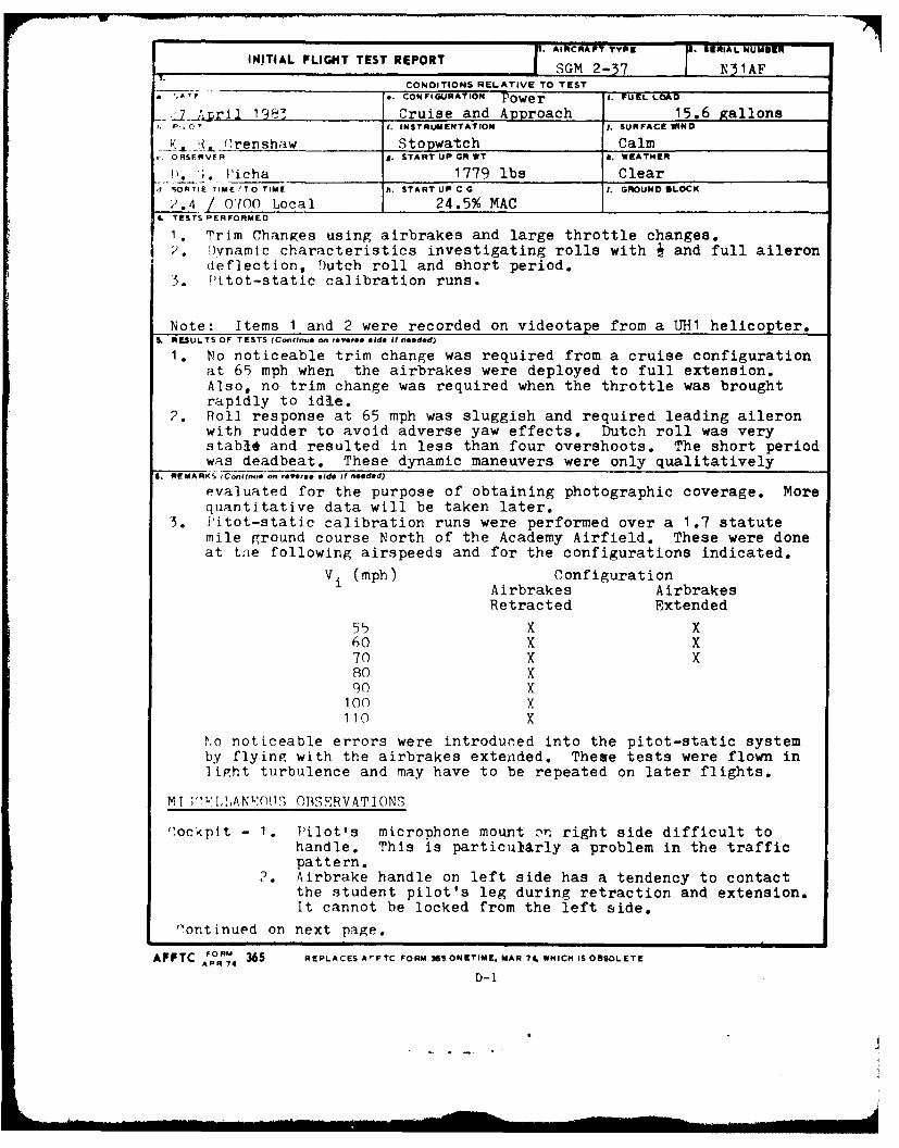
. AIRCRAFT TYPE j RIAL NUMBERINiTAL FLIGHT TEST REPORT SGM 2-37 N31AF
CONDITIONS RELATIVE TO TEST
CONFIGURATION Power I. FUEL LOAD
..2_,ril 1983 Cruise and Approach 15.6 gallonsP, 0) 1. INSTRUMENTATION j. SURFACE WIND
K (_!.'., 1renshaw Stopwatch CalmORSERVIR g. START UP GR WT J. WEATHER
*1. (;. Picha 1779 lbs Clear,I SORTiE TIMEI 'TO TIME h. START UP C G I. GROUND BLOCK
2.4 / 0700 Local 24.5% MAC4. TESTS PERFORMED
1. Trim Changes using airbrakes and large throttle changes.2. l)ynamic characteristics investigating rolls with j and full aileron
deflection, Dutch roll and short period.5. fPitot-static calibration runs.
Note: Items 1 and 2 were recorded on videotape from a UHI helicopter.S. RESULTS OF TESTS (Continue on reverse aide It needed)
1. No noticeable trim change was required from a cruise configurationat 65 mph when the airbrakes were deployed to full extension.Also, no trim change was required when the throttle was broughtrapidly to idle.
2. Roll response at 65 mph was sluggish and required leading aileronwith rudder to avoid adverse yaw effects. Dutch roll was verystable and resulted in less than four overshoots. The short periodwas deadbeat. These dynamic maneuvers were only qualitatively
6. REMARKS (Continu~e on everse. aide It needed)
evaluated for the purpose of obtaining photographic coverage. Morequantitative data will be taken later.
3. litot-static calibration runs were performed over a 1.7 statutemile ground course North of the Academy Airfield. These were doneat tne following airspeeds and for the configurations indicated.
Vi (mph) ConfigurationAirbrakes Airbrakes
Retracted Extended
55 X X60 X X70 X X80 X90 X
100 X110 X
No noticeable errors were introduced into the pitot-static systemby flying with the airbrakes extended. These tests were flown intight turbulence and may have to be repeated on later flights.
MT ;m' I,,AN'/MUT OBSERVATIONS
"ockpit - 1. Pilot's microphone mount nr right side difficult tohandle. This is particularly a problem in the trafficpattern.
2. Airbrake handle on left side has a tendency to contactthe student pilot's leg during retraction and extension.It cannot be locked from the left side.
Oontinued on next page.
AFFTC FORM 365 REPLACES AIFTC FORM ISS ONETIME. MAR 70. WHICH IS OBSOLETEAPR -1
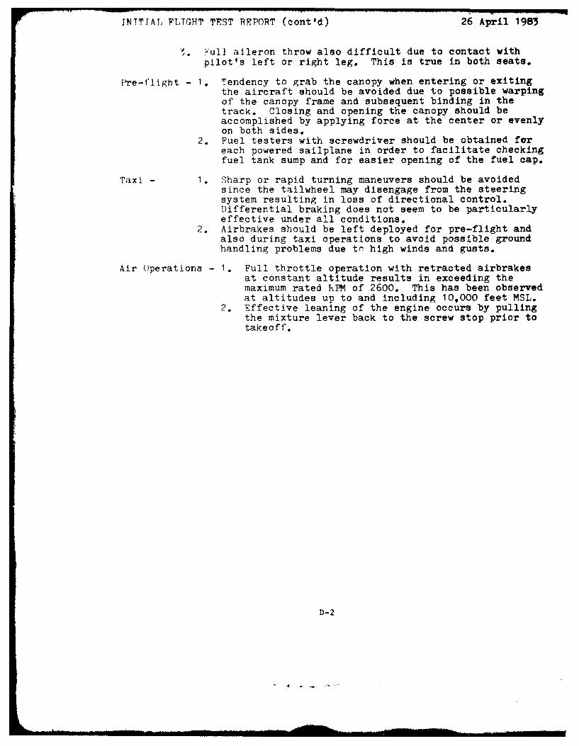
INTTIAL FLIGHT TEST REPORT (cont'd) 26 April 1983
7. wul] aileron throw also difficult due to contact withpilot's left or right leg. This is true in both seats.
Pre-flight - 1. Tendency to grab the canopy when entering or exitingthe aircraft should be avoided due to possible warpingof the canopy frame and subsequent binding in thetrack. Closing and opening the canopy should beaccomplished by applying force at the center or evenlyon both sides.
2. Fuel testers with screwdriver should be obtained foreach powered sailplane in order to facilitate checkingfuel tank sump and for easier opening of the fuel cap.
Taxi - I. Sharp or rapid turning maneuvers should be avoidedsince the tailwheel may disengage from the steeringsystem resulting in loss of directional control.Differential braking does not seem to be particularlyeffective under all conditions.
2. Airbrakes should be left deployed for pre-flight andalso during taxi operations to avoid possible groundhandling problems due tr' high winds and gusts.
Air Operations - 1. Full throttle operation with retracted airbrakesat constant altitude results in exceeding themaximum rated RPM of 2600. This has been observedat altitudes up to and including 10,000 feet MSL.
2. Effective leaning of the engine occurs by pullingthe mixture lever back to the screw stop prior totakeoff.
D-2
... .... .. m ... . .. - mm a m m nmm mnn -C -- .
AD-A31 445 LMITED PERFORMANCE AND FLYNOGQUAL1TE5U VLDAIN OF /
.- RT RNHWE
A U 3UAA N8HE
S M 2-37 POWERED SA LPA E U) A_ FORCE ACADEMY CO
LIIIII - B.°Io
MICROCOPY RESOLUTION TEST CHART
NATIONAL 9UREAU O STANOARDS- 963- A
C. a
. AIRCRAFT TYPE 2. SERIAL NUMMIER
INITIAL FLIGHT TEST REPORT 2J SGM 2-7 N31 AF
" DACONDITIONS RELATIVE TO TESTD 0ATE " ,. CONFIGURATION h FUEL LO
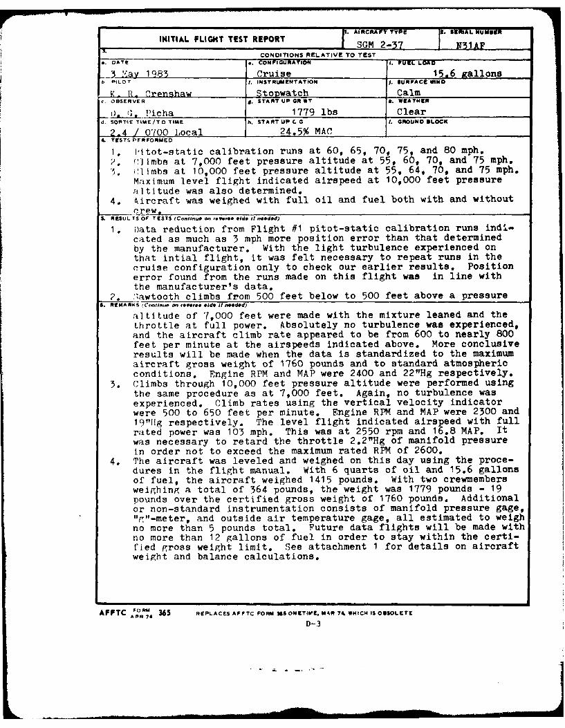
3 May 1983 Cruise 15,6 gallonsb PILOT t. INSTRUMENTATION I. SURFACE WINO
K. R_ Crenshaw Stopwatch CalmOBSERVER m. START UP GR WT k. WEATHER
i). ]. Picha 1779 lbs Cleard. SORTIE TIME/TO TIME h. START UP C G I. GROUND @LOK
2.4 1 0700 Local 24.5% MAC4 TESTS PrRFORMED
1. Pitot-static calibration runs at 60, 65, 70, 75, and 80 mph.2. r:limbs at 7,000 feet pressure altitude at 55, 60, 70, and 75 mph.5. ('l mbs at 10,000 feet pressure altitude at 55, 64, 70, and 75 mph.
Maximum level flight indicated airspeed at 10,000 feet pressurealtitude was also determined.
4. Aircraft was weighed with full oil and fuel both with and withoutcr_!ew,0
S, RESULTS OF TESTS (Confinuon @ Ver.. aide I needed)
1. Data reduction from Flight #1 pitot-static calibration runs ind.-
cated as much as 3 mph more position error than that determinedby the manufacturer. With the light turbulence experienced onthat intial flight, it was felt necessary to repeat runs in thecruise configuration only to check our earlier results. Positionerror found from the runs made on this flight was in line withthe manufacturer's data.
2. "awtooth climbs from 500 feet below to 500 feet above a pressureS. REMARKS rC.,nt1ne on rev. sid. I n**dd)
altitude of 7,000 feet were made with the mixture leaned and thethrottle at full power. Absolutely no turbulence was experienced,and the aircraft climb rate appeared to be from 600 to nearly 800feet per minute at the airspeeds indicated above. More conclusiveresults will be made when the data is standardized to the maximumaircraft gross weight of 1760 pounds and to standard atmosphericconditions. Engine RPM and MAP were 2400 and 22"Hg respectively.
3. Climbs through 10,000 feet pressure altitude were performed usingthe same procedure as at 7,000 feet. Again, no turbulence wasexperienced. Climb rates using the vertical velocity indicatorwere 500 to 650 feet per minute. Engine RPM and MAP were 2300 and191"1ig respectively. The level flight indicated airspeed with fullrated power was 103 mph. This was at 2550 rpm and 16.8 MAP. Itwas necessary to retard the throttle 2.2"Hg of manifold pressurein order not to exceed the maximum rated RPM of 2600.
4. The aircraft was leveled and weighed on this day using the proce-dures in the flight manual. With 6 quarts of oil and 15.6 gallonsof fuel, the aircraft weighed 1415 pounds. With two crewmembersweighing a total of 364 pounds, the weight was 1779 pounds - 19pounds over the certified gross weight of 1760 pounds. Additionalor non-standard instrumentation consists of manifold pressure gage,"g"-meter, and outside air temperature gage, all estimated to weighno more than 5 pounds total. Future data flights will be made withno more than 12 gallons of fuel in order to stay within the certi-fied gross weight limit. See attachment 1 for details on aircraftweight and balance calculations.
AFFTC FORM 365 REPLACES AFFTC FORM 35 ONETIVE. MhfR 74. WHICH IS OSSOLETE
APR 74
D-3
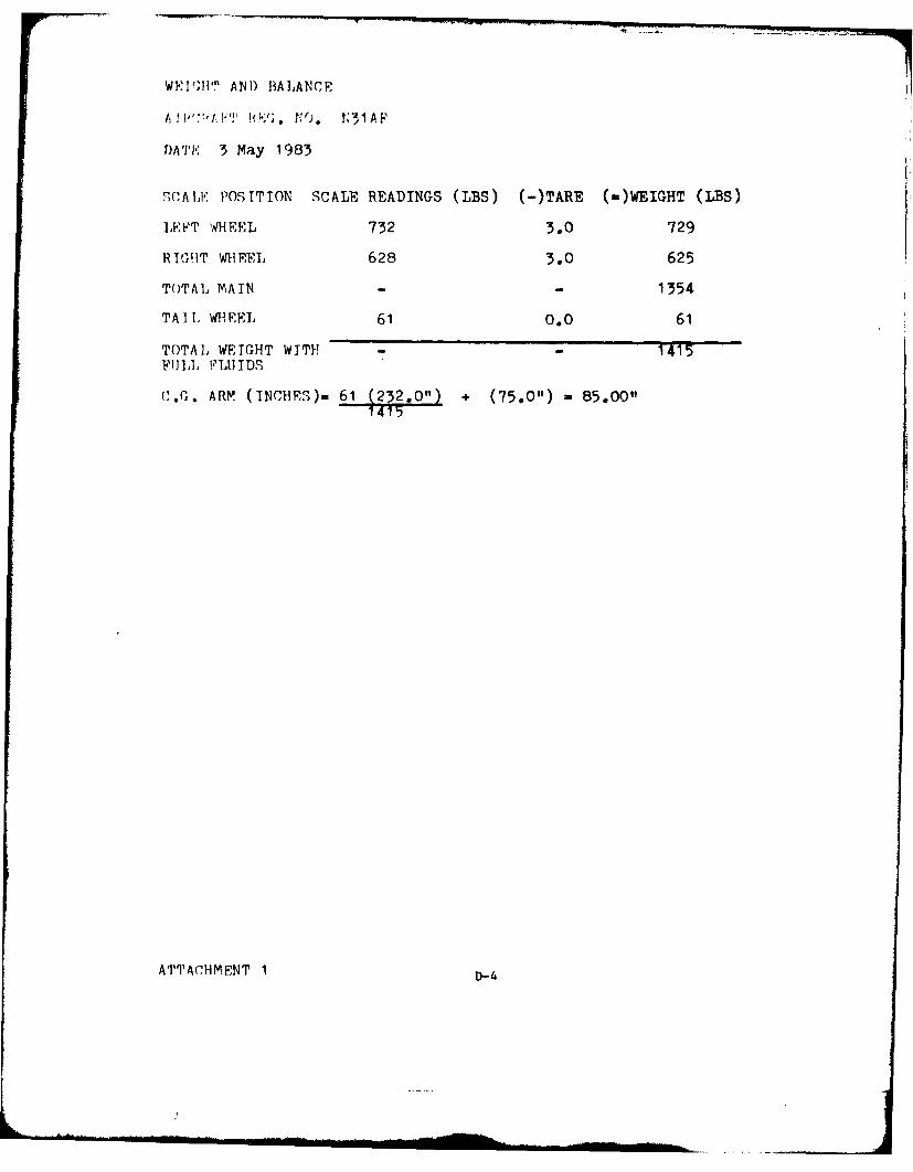
WEI'PHT AN) BALANCE
A I ;,':'I. T 1;. . N31AF
t)AT'E 3 May 1983
,CAIXE POSITION SCALE READINGS (LBS) (-)TARE (-)WEIGHT (LBS)
LEFT WHEEL 732 3.0 729
REI(H1T WHEEL 628 3.0 625
TOTAL MAIN - - 1354
TAIl, WtiEEL 61 0.0 61
TOTAL WEIGHT WITH! - 1415FULL FLUIDS
C.G. ARM (INCHES) 61 232.0") + (75.0") 85.00"1415
ATTACHMENT I D-4
INITIAL FLIGHT TEST REPORT AI2CRAFT- T3V7 NERIAL FMUU
J SGM 2-37 r 3AF__ _CONDITIONS RELATIVE TO TEST
., DATE .- CONFIGURATION i. FUEL LOAD
S"aY 10()3 Cruise 1P. PILOY I. INSTRUMENTATION j. SURFACE WIN
K_ Fl- 'rnshaw Cassette Tape Recorder CalmOSERVN . START UP K WT I. WEATHER
d. E..- cha 1771 lbs Cleard. SORTIE TIME/TO TIME h. START UP C G . GROUND OLOCK
2 .,L / 0715 Local 24.5% MAC_ _ _ _ _ _ _ _ _ _ _
4. TESTS PERFORMED
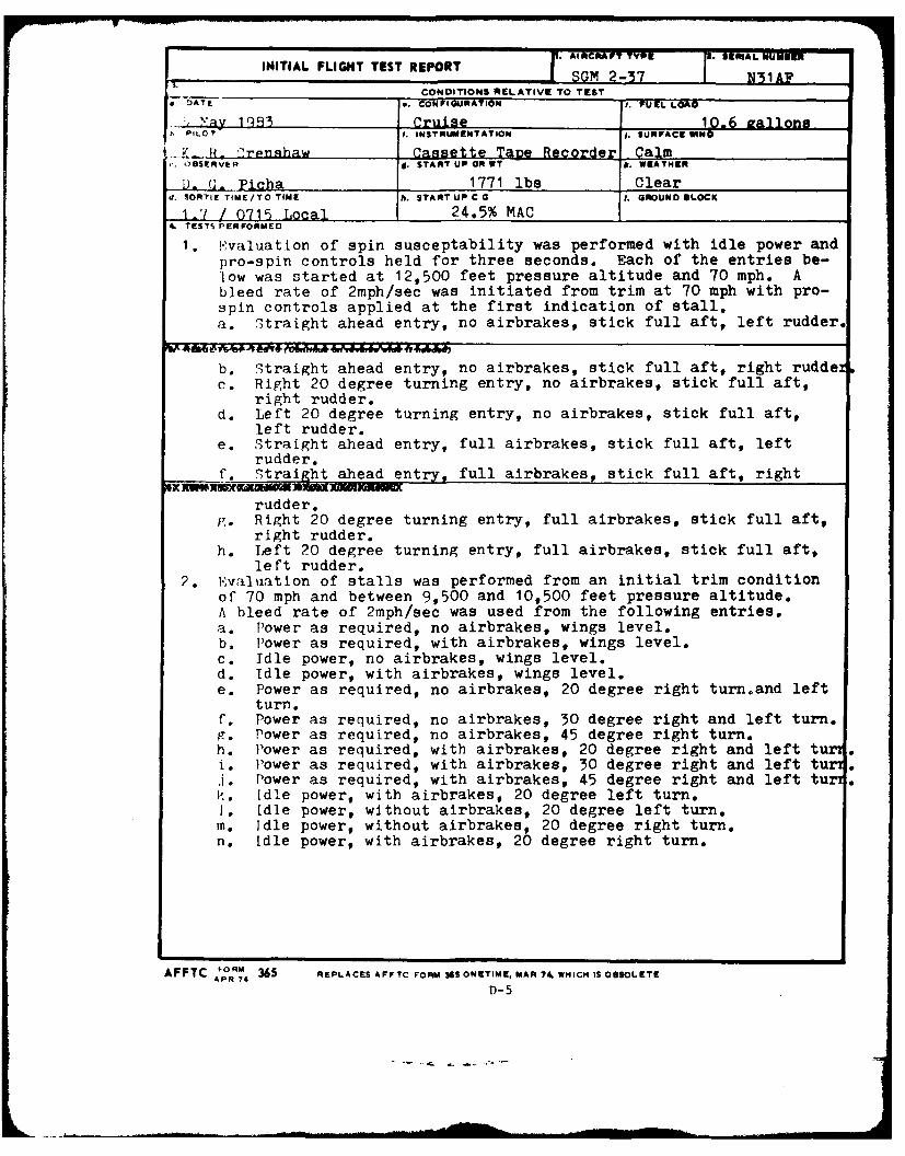
I. !,valuation of spin susceptability was performed with idle power andpro-spin controls held for three seconds. Each of the entries be-low was started at 12,500 feet pressure altitude and 70 mph. Ableed rate of 2mph/sec was initiated from trim at 70 mph with pro-spin controls applied at the first indication of stall.a. Straight ahead entry, no airbrakes, stick full aft, left rudder.
b. Straight ahead entry, no airbrakes, stick full aft, right rudderc. Right 20 degree turning entry, no airbrakes, stick full aft,
right rudder.d. Left 20 degree turning entry, no airbrakes, stick full aft,
left rudder.e. Straight ahead entry, full airbrakes, stick full aft, left
rudder.f. Straight ahead entry, full airbrakes, stick full aft, right
rudder.g. Right 20 degree turning entry, full airbrakes, stick full aft,
right rudder.h. Left 20 degree turning entry, full airbrakes, stick full aft,
left rudder.2. E' valuation of stalls was performed from an initial trim condition
of 70 mph and between 9,500 and 10,500 feet pressure altitude.A bleed rate of 2mph/sec was used from the following entries.a. Power as required, no airbrakes, wings level.b. [lower as required, with airbrakes, wings level.c. Idle power, no airbrakes, wings level.d. Idle power, with airbrakes, wings level.e. Power as required, no airbrakes, 20 degree right turnoand left
turn.f. Power as required, no airbrakes, 30 degree right and left turn.p. Power as required, no airbrakes, 45 degree right turn.h. Power as required, with airbrakes, 20 degree right and left turi. Power as required, with airbrakes, 30 degree right and left turJ. Power as required, with airbrakes, 45 degree right and left tu .P'. Idle power, with airbrakes, 20 degree left turn.1. Idle power, without airbrakes, 20 degree left turn.m. Idle power, without airbrakes, 20 degree right turn.n. Idle power, with airbrakes, 20 degree right turn.
AF PTC ORM 365 REPLACES AFFTC FORM 365 ONETIME, MAR 74. WHICH IS OSOLETEAPR 74D- 5
TNITIAL FLIGHT TFST REPORT (cont'd) 5 May 1983
5. RFMARKS
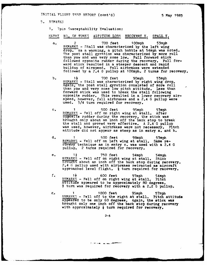
1. Spin Susceptability Evaluation:
ENTRY NO. OF TURNS ALTITUDE LOSS RECOVERY V4 STALL V
a. 2 700 feet 10Omph 53mphREMARKS - Stall was characterized by the left wingdrop. As a warning, a pitch bobble at 54mph was noted.The post stall gyration was characterized by more rollthan yaw and was very nose low. Full forward stickfollowed opposite rudder during the recovery. Full for-ward stick resulted in a steeper descent and rapidbuildup of airspeed. Full airbrakes were extendedfollowed by a 2.4 G pullup at 1OOmph. 2 turns for recovery.
b. 11 700 feet 90mph 53mphREMARKS - Stall was characterized by right wing drop.Again, the post stall gyration consisted of more rollthan yaw and very nose low pitch attitude. Less thanforward stick was used to break the stall followingopposite rudder. This resulted in a lower recovery air-speed, however, full airbrakes and a 2.4 G pullup wereused. 3/4 turn required for recovery.
c. 1 500 feet 95mph 53mphREMARKS - Fell off on right wing at stall. Afteropposite rudder during the recovery, the stick wasbrought only about an inch off the back stop to breakthe stall and proved very effective. A 2.4 G pullupwas used, however, airbrakes were not necessary. Pitchattitude did not appear as steep as in entry a. and b.
d. 1 500 feet 98mph 53mphREMARKS - Fell off on left wing at stall, Same re-covery technique as in entry c. was used with a 2.4 Gpullup. 2 turns required for recovery.
e. i* 750 feet 94mph 54mphREMARKS - Fell off on right wing at stall. Stickbrought about an inch off the back stop during recovery.2.4 G pullup used with airbrakes retracted as aircraftapproached level flight. turn required for recovery.
if. 1 600 feet 97mph 54mphREMARKS - Fell off on right wing at stall. Pitchattitude appeared to be approximately 80 degrees.
turn was required for recovery with a 2.2 G pullup.
g. 1 1000 feet 95mph 57mphREMATIK5 - Fell off to the right at stall. Pitch attitudeappeared to be only 60 degrees. Again, the stick wasbrought only one inch off the back stop during recoverywith approximately * turn required for recovery.
D-6
'""T 'IAL :,"T'T, TEST REPORT (cont'd) 5 May 1983
'.. H'"APK2 (cont'd)
1. ';pin Susceptability Evaluation (cont'd):
F-rITHY NO. OF TURNS ALTITUDE LOSS RECOVERY V, STALL V
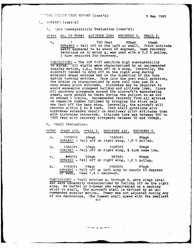
h. 1 750 feet 92mph 54mphREMARKS - Fell off to the left at stall. Pitch attitudeagain appeared to be about 60 degrees. Same recoverytechnique as in entry g. was used with a 2.2 G pullup.I turn required for recovery.
rONCLUSIONS - The SGM 2-37 exhibits high susceptabilityto spins. All stalls were characterized by an uncommandedangular motion, i.e., drop off on a wing. Generally, theaircraft tended to drop off on the right wing duringstraight ahead entries and in the direction of the turnduring turning entries. Once into the post stall gyration,the motion is characterized by more roll than yaw in avery steep pitch attitude. Airbrakes may be required toavoid excessive airspeed buildup and altitude loss. Sinceall recovery airspeeds exceed the aircraft's maneuveringspeed, care should be taken during the pullout so as notto exceed G limits. Recommended recovery from all entriesis opposite rudder followed by bringing the stick onlyone inch off the back stop. Generally, the aircraft willrecover within 1 to i turn. Post stall gyrations withairbrakes extended result in shallower pitch attitudes thanwith airbrakes retracted. Altitude loss was between 500 to1000 feet with recovery airspeeds between 90 and 1OOmph.
2. Stall Evaluation:
.TTRY ITART ALT. STALL V. RECOVERY ALT. RECOVERY V
a. 10380ft 48mph IO400ft 80mphREMARKS - Fell off on right wing. 1.8 G pullup.
b. 10450ft 52mph IOO5Oft 90mphREMARKS - Fell off on right wing. J turn nose low.
c. 9800ft 52mph 9659ft 80mphREMARKS - Fell off on right wing. 1.8 G pullup.
d. lOSOOft 53mph lOOOOft 87mphREMARKS - Fell off on left wing to nearly 60 degreesof bank. Used 1.4 G recovery.
SONCLUSTONS - Stall entries a. through d. were wings leveland were generally characterized by falling off on the rightwing. No buffet or G-break was experienced as a warningprior to stall. The aircraft stall is defined by an un-commanded angular motion. Power was not adjusted during anyof the recoveries. The lowest stall speed with the smallest
D-7
INITIAL R]T;HT TEST REPORT (cont'd) 5 May 1983
P, XV ,TA i ': (conit'd)
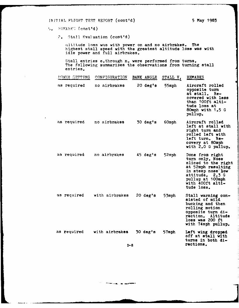
2. 2tall Rvaluation (cont'd)
altitude loss was with power on and no airbrakes. Thehighest stall speed with the greatest altitude loss was withidle power and full airbrakes.
Stall entries e.through n. were performed from turns.The following summarizes the observations from turning stallentries.
!'O1W l SETTTNG CONFIGURATION BANK ANGLE STALL V REMARKS
as required no airbrakes 20 deg's 55mph Aircraft rolledopposite turnat stall. Re-covered with lessthan 10Oft alti-tude loss at80mph with 1.5 Gpullup.
as required no airbrakes 30 deg's 60mph Aircraft rolledleft at stall withright turn androlled left withleft turn. Re-covery at 80mphwith 2.0 G pullup.
as required no airbrakes 45 deg's 52mph Done from rightturn only. Nosesliced to the rightat 52mph resultingin steep nose'lowattitude. 2.3 Gpullup at 100mphwith 400ft alti-tude loss.
as required with airbrakes 20 deg's 53mph Stall warning con-sisted of mildbucking and thenrolling motionopposite turn di-rection. Altitudeloss was 200 ftwith 74mph pullup.
as required with airbrakes 30 deg's 57mph Left wing droppedoff at stall withturns in both di-
D-8 rections.
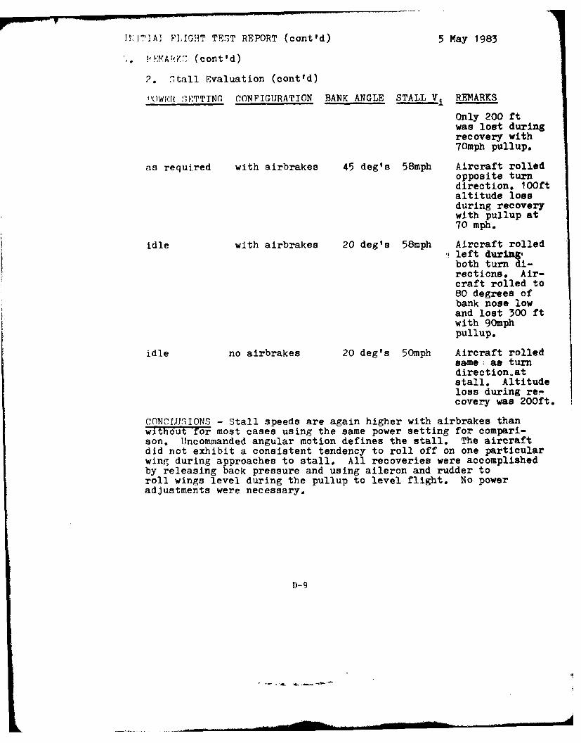
!T:rT]A] FLIGHT TEST REPORT (cont'd) 5 May 1983
, d!.,:MA14 2 (cont'd)
2. Stall Evaluation (cont'd)
I()WN. :;K7TTNG CONFIGURATION BANK ANGLE STALL Vi REMARKS
Only 200 ftwas lost duringrecovery with70mph pullup.
as required with airbrakes 45 deg's 58mph Aircraft rolledopposite turndirection. 10Oftaltitude lossduring recoverywith pullup at70 mph.
idle with airbrakes 20 deg's 58mph Aircraft rolled' left during,both turn di-rections. Air-craft rolled to80 degrees ofbank nose lowand lost 300 ftwith 90mphpullup.
idle no airbrakes 20 deg's 50mph Aircraft rolledsome; as turndirection.atstall. Altitudeloss during re-covery was 200ft.
CONCLUSIONS - Stall speeds are again higher with airbrakes thanwithout for most cases using the same power setting for compari-son. Uncommanded angular motion defines the stall. The aircraftdid not exhibit a consistent tendency to roll off on one particularwing during approaches to stall. All recoveries were accomplishedby releasing back pressure and using aileron and rudder toroll wings level during the pullup to level flight. No poweradjustments were necessary.
D-9
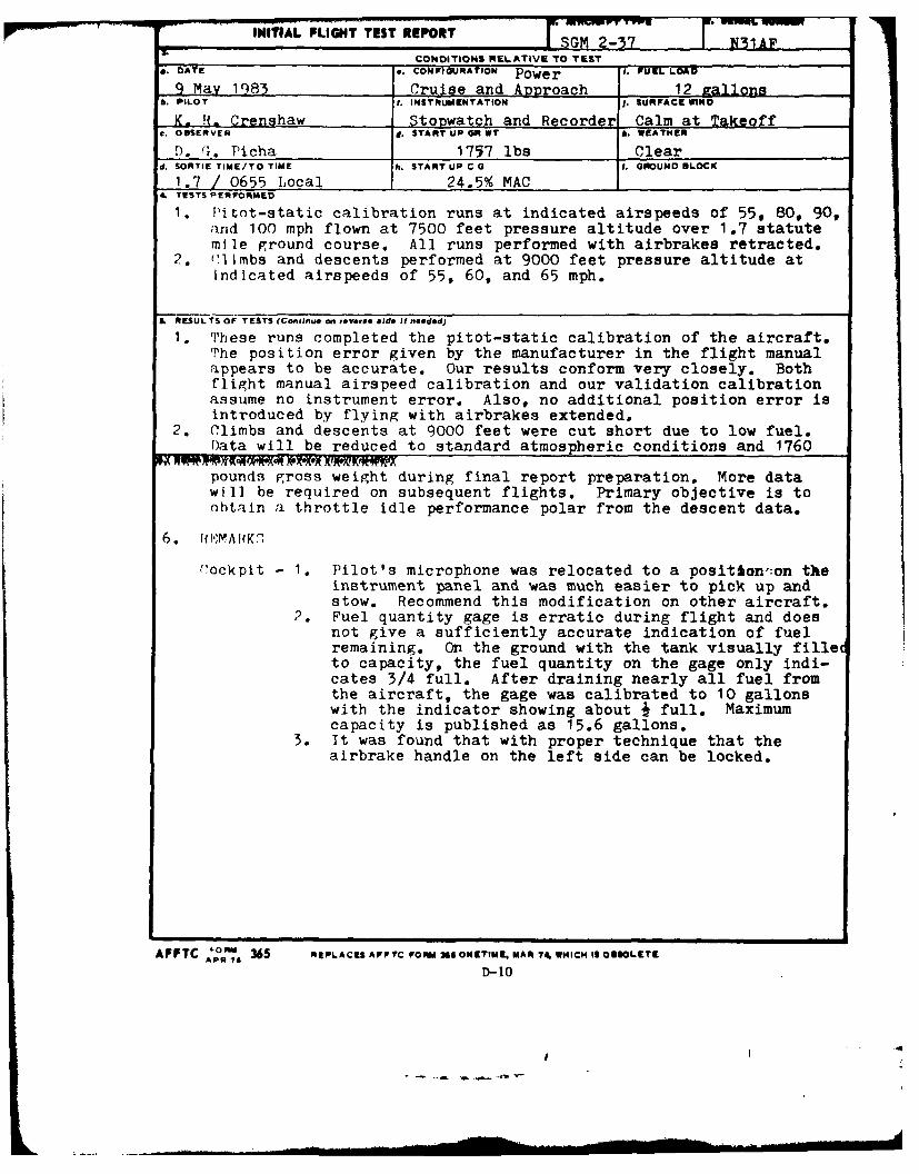
INITIAL PLIGHT TEST REPORT SGM 2-37 E31AFCONDITIONS RELATIVE TO TEST
. DATE .. CONFIGURATION Power i. UF LOAD
9 May 1q83 Cruise and Approach 12 rallons6. PILOT I. INSTRUMENTATION . SURFACE WINO
K. R.. Crenshaw StoDwatch and Recorder Calm at Takeoffc. OBSERVER 1. START UP OR WT h. WEATHER
1). (,. Picha 1757 lbs Cleard. SORTIE TIME/TO TIME h. START UP C G 5. GROUND BLOCK
1.7 / 0655 Local 24.5% MAC4 TESTS PERFORMED
1. Pitot-static calibration runs at indicated airspeeds of 55, 80, 90,and 100 mph flown at 7500 feet pressure altitude over 1.7 statutemile ground course. All runs performed with airbrakes retracted.
2. ('limbs and descents performed at 9000 feet pressure altitude atindicated airspeeds of 55, 60, and 65 mph.
L RESULTS OF TESTS (Connue on ,.Vere *)d. It needed)
1. These runs completed the pitot-static calibration of the aircraft.The position error given by the manufacturer in the flight manualappears to be accurate. Our results conform very closely. Bothflight manual airspeed calibration and our validation calibration
assume no instrument error. Also, no additional position error isintroduced by flying with airbrakes extended.
2. Climbs and descents at 9000 feet were cut short due to low fuel.Data will be reduced to standard atmospheric conditions and 1760
pounds gross weight during final report preparation. More datawill be required on subsequent flights. Primary objective is to
obtain a throttle idle performance polar from the descent data.
6. RNMA-K1
('ockpit - 1. Pilot's microphone was relocated to a position:on theinstrument panel and was much easier to pick up andstow. Recommend this modification on other aircraft.
2. Fuel quantity gage is erratic during flight and doesnot give a sufficiently accurate indication of fuelremaining. On the ground with the tank visually filleto capacity, the fuel quantity on the gage only indi-cates 3/4 full. After draining nearly all fuel fromthe aircraft, the gage was calibrated to 10 gallonswith the indicator showing about J full. Maximumcapacity is published as 15.6 gallons.
3. It was found that with proper technique that theairbrake handle on the left side can be locked.
APPTC "ORm 365 REPLACES AFFTC FOM 36S ONKTIM9. MAR 74, WMICH IS OBSOLETE
D-10
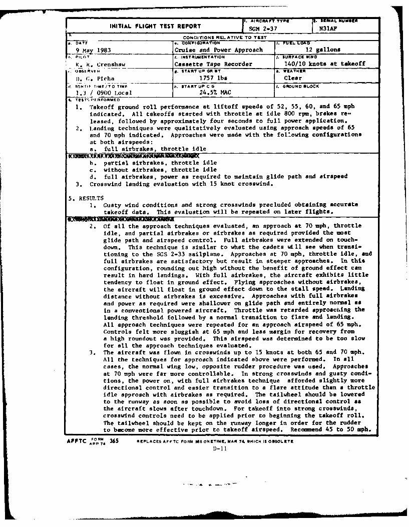
AIRCRAP TYPE . SERIAL NUMMERINITIAL FLIGHT TEST REPORT SGM 2-37 N3IAF
_ _ _ _ CONDITIONS RELATIVE TO TESTa. DATI e. CONFIGURATION I. FUEL LOAD
9 a_M 1983 Cruise and Power Approach 12 gallonst. PILOT I. INSTRUMENTATION 1. SURFACE WIND
K. R. Crenshaw Cassette Tape Recorder 140/10 knots at takeoff,OBI: RVE N S. START UP OR WT k. WEATHER
n. C. Picha 1757 lbs Clear.f. 1IONTIFE TIMFE/TO TIME h. START UP CO I . GROUND @LOCK
1.0 / 0900 Local 24.5% MAC4. TIST' Pf RFORMED
1. Takeoff ground roll performance at liftoff speeds of 52, 55, 60, and 65 mphindicated. All takeoffs started with throttle at idle 800 rpm, brakes re-leased, followed by approximately four seconds to full power application.
2. tanding techniques were qualitatively evaluated using approach speeds of 65and 70 mph indicated. Approaches were made with the foll.owing configurationsat both airspeeds:a. full airbrakes, throttle idle
b. partial airbrakes, throttle idlec. without airbrakes, throttle idled. full airbrakes, power as required to maintain glide path and airspeed
3. Crosswind landing evaluation with 15 knot crosswind.
5. RESULTS1. Gusty wind conditions and strong crosswinds precluded obtaining accurate
takeoff data. This evaluation will be repeated on later flights.
2. Of all the approach techniques evaluated, an approach at 70 mph, throttleidle, and partial airbrakes or airbrakes as required provided the mostglide path and airspeed control. Full airbrakes were extended on touch-down. This technique is similar to what the cadets will see when transi-tioning to the SGS 2-33 sailplane. Approaches at 70 mph, throttle idle, andfull airbrakes are satisfactory but result in steeper approaches. In thisconfiguration, rounding out high without the benefit of ground effect canresult in hard landings. With full airbrakes, the aircraft exhibits littletendency to float in ground effect. Flying approaches without airbrakes,the aircraft will float in ground effect down to the stall speed. Landingdistance without airbrakes is excessive. Approaches with full airbrakesand power as required were shallower on glide path and entirely normal asin a conventional powered aircraft. Throttle was retarded approact.ing thelanding threshold followed by a normal transition to flare and landing.All approach techniques were repeated for an approach airspeed of 65 mph.Controls felt more sluggish at 65 mph and less margin for recovery froma high roundout was provided. This airspeed was determined to be too slowfor all the approach techniques evaluated.
3. The aircraft was flown in crosswinds up to 15 knots at both 65 and 70 mph.All the techniques for approach indicated above were performed. In allcases, the normal wing low, opposite rudder procedure was used. Approachesat 70 mph were far more controllable. In strong crosswinds and gusty condi-tions, the power on, with full airbrakes technique afforded slightly moredirectional control and easier transition to a flare attitude than a throttleidle approach with airbrakes as required. The tailwheel should be loweredto the runway as soon as possible to avoid loss of directional control asthe aircraft slows after touchdown. For takeoff into strong crosswinds,crosswind controls need to be applied prior to beginning the takeoff roll.The tailwheel should be kept on the runway longer in order for the rudderto become more effective prior to takeoff airspeed. Recomend 45 to 50 mph.
AFFTC FORM 365 REPLACES AFFTC FORM 368 ONETIME. MAR 74 WHICH IS OBSOLETEAPR 74 D-11
Al AIRCRA rT TYPEl IFIWAL IMUVNr
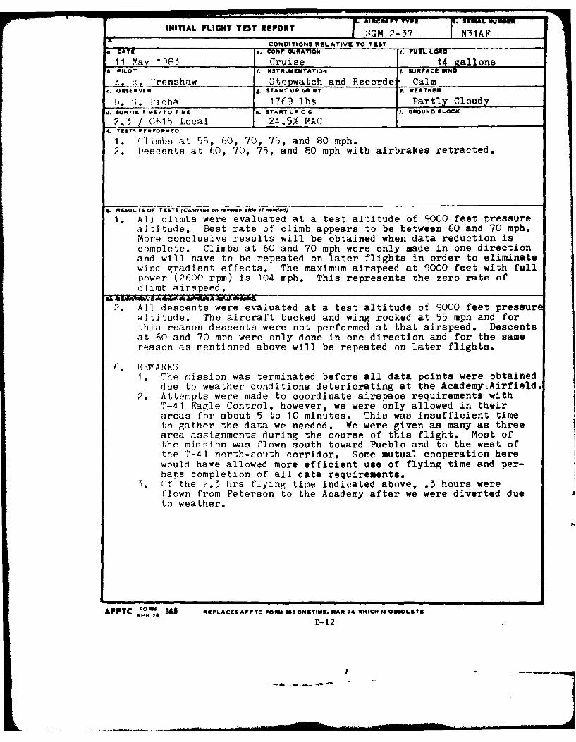
INITIAL FLIGHT TEST REPORT GM 2-37 N31AP
CONDITIONS RELATIVE TO TUSTa. OATC . CoNFIGURATION I. FUEIL LOAD
11 May 1)S5 Cruise 14 gallonsb. PILOT 1. INSTRUMENTATION J. SURFACE WIND
.',; ,"renshaw Stopwatch and Recorder Calmc. OSSEAVER d. START UP GR WT k. WEATHER
1,. 1;. ioicha 1769 lbs Partly Cloudyd. SORTIE TIME/TO TIME h. START UP C G 1. GROUNO IILOCK
25 / ()15 Local 24.5% MAC.TESTS PERFORMED
1. ('limbs at 55, 60, 70, 75, and 80 mph.2. lIescents at 60, 70, 75, and 80 mph with airbrakes retracted.
S. RESULTS OF TESTS (Continue on revere. ed. It needed)
1. All climbs were evaluated at a test altitude of 9000 feet pressurealtitude. Best rate of climb appears to be between 60 and 70 mph.More conclusive results will be obtained when data reduction iscomplete. Climbs at 60 and 70 mph were only made in one directionand will have to be repeated on later flights in order to eliminatewind gradient effects. The maximum airspeed at 9000 feet with fullpower (2600 rpm) is 104 mph. This represents the zero rate ofclimb airspeed.
2. All descents were evaluated at a test altitude of 9000 feet pressurealtitude. The aircraft bucked and wing rocked at 55 mph and forthis reason descents were not performed at that airspeed. Descentsat 60 and 70 mph were only done in one direction and for the samereason as mentioned above will be repeated on later flights.
C,. u*;MAR KS1. The mission was terminated before all data points were obtained
due to weather conditions deteriorating at the Academy;Airfield.2. Attempts were made to coordinate airspace requirements with
T-41 Eagle Control, however, we were only allowed in theirareas for about 5 to 10 minutes. This was insufficient timeto gather the data we needed. We were given as many as threearea assignments during the course of this flight. Most ofthe mission was flown south toward Pueblo and to the west ofthe P-41 north-south corridor. Some mutual cooperation herewould have allowed more efficient use of flying time and per-haps completion of all data requirements.
. f the 2.3 hrs flying time indicated above, .3 hours wereflown from Peterson to the Academy after we were diverted dueto weather.
AFFTC ORM 365 REPLACES AFFTC FORM 38 ONETIME. MAR 74 WHICH IS OB9OLETEAPR 74
D-12
1I. AIRCRAFT TYPE 2. SERIAL INUMNIR
INITIAL FLIGHT TEST REPORT I S(;M 2-37 NIl AF
CONDITIONS RELATIVE TO TEST;i I te. CONFIGURATION 1. FUEL LOAU
Mtvi~iCruise and Power Approach 12 gallons0 1. INSTRUMENTATION I.SURFACE WIND
- _____ Cassette Tape Recorder Calmh~tRVk,, 1 START UP GR WT Jr. WEATHEII
UI (i-11 1750 l bs Clear
d. rIOR"TiP "Mr/TO TIME h. START Up C G 1. GROUND BLOCK
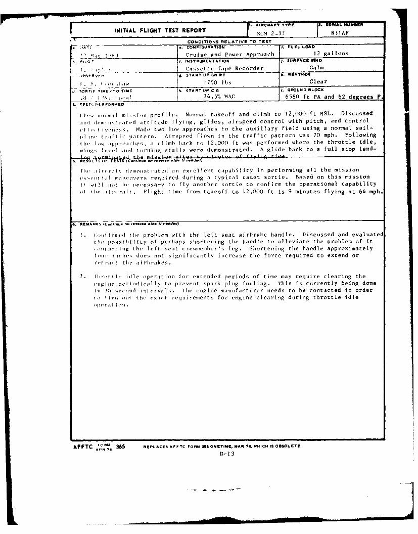
.9,I/ ~(I11 24.5. MAC 6580 ft PA and 62 degrees F.
4. TO5'S dtVRMEO
[I or-mi! f~ profile. Normal takeoff and climb to 12,000 ft MSL. Discussed
h[d 1-11 .rist r;Itcn(l ,Ittitude flying, glides, airspeed control with pitch, and control
v IIt,~ r ivss . Made two low approaches to the auxiliary field using a normal sail-
p]lIII. I 1.1f I ipattern. Airspeed flown in the traffic pattern was 70 mph. Following
t he I ow 11)1) ro.rcs , aI ci mb back to 12,000 ft was performed where the throttle idle,
wingq lov'tl and turning stalls were demonstrated. A glide hack to a full stop land-
OF TESTS~ E(Contnue oe reverse aZcIInedd
I'loIr i .1'1 derriouist rated ant exce IIent capability in performing all the mission
vs,rcrt iiit manotuvers required during a typical cadet sortie. Based on this mission
iwill rot bre niecessary to fly another sortie to confirm the operational capability
ItI -I If r( raI r . Flight time from takeoff to 12,000 ft is '4 minutes flying at 64 mph.
S. REMARKS 1C,,ntknu "n reverse ads, it needed)
Coit I ired tlire probl em wi th the l ef t seat ai rbrake handle. Discussed and evaluated
Htr piossibirlity of perhaps s'-ortening the handle to alleviate the problem of it
oourtct ing the left seat crewmember's leg. Shortening the handle approximately
forir inches; does nor significantly increase the force required to extend or
ret ract the a i rrakes.
. hirottle idle operation for extended periods of time may require clearing the
engine periodically to prevent spark plug fouling. This is currently being done
i 3I second intervals. The engine manufacturer needs to be contacted in order
to finld out the exact requirements for engine clearing during throttle idleopvr ra t ioni.
AFFTC 'O"M 365 REPLACES AF FTC FORM 365 ONETIME, MAR 74~ WMICH IS OBSOLETEAPR 74
D3-13
1. AIRCRAFT TYPE a. SERIAL NUMIER
INITIAL FLIGHT TEST REPORT SGM 2-37 N31AF
CONDITIONS RELATIVE TO TEST• OA i . CONFIGURATION Fower i. FUEL LOAD
.ruise and Approach 15.0 gallons1. INSTRUMENTATION Tape 1. SURFACE WINO
k, . ,,,mh:,w ;to2pwatch and Recorder 330/10 knots. 0,hlP" 1r. g. START UP OR WT J. WEATHER
I,. *. I I,-1,, 17711 ClearJ bd'fIL: c/I* 1IMV h. bIANTUP
( -Q( I. GROUNO LOCK
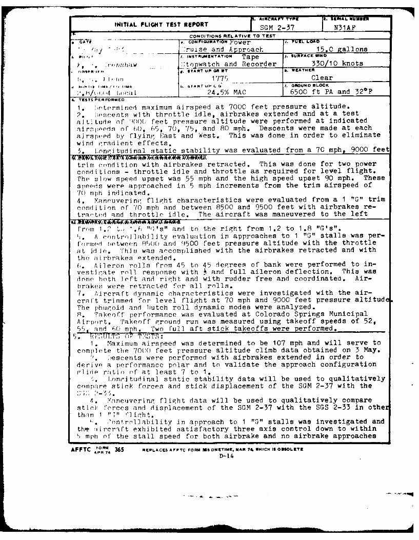
;'.1/,*(4 I,)C:il 24.5% MAC 6500 ft PA and 32*F4 TESTS PERFORMED
1. 1jetermined maximum airspeed at 7000 feet pressure altitude.
2. iposcents with throttle idle, airbrakes extended and at a test
altitude of 'oo0 feet pressure altitude were performed at indicatedalr"joeds of 0, 05, 70, 75, and 80 mph. Descents were made at eachajrsped by flyinf- East and West. This was done in order to eliminatewind igradient effects.
5. L onritudinal static stability was evaluated from a 70 mph, 9000 feet
trim condition with airbrakes retracted. This was done for two power
conditions - throttle idle and throttle as required for level flight.The slow speed upset was 55 mph and the high speed upset 90 mph. These
speeds were approached in 5 mph increments from the trim airspeed of70 mph indicated.
4. Maneuvering; flight characteristics were evaluated from a 1 "G" trimcondition of 70 mph and between 8500 and 9500 feet with airbrakes re-trar'ted and throttle idle. The aircraft was maneuvered to the left
from 1.? t- 1•0 "(I's" and to the right from 1.2 to 1.8 "G's".',. A controllability evaluation in approaches to 1 "G" stalls was per-l,)r'mr(d between 850( and ()500 feet pressure altitude with the throttle'It Id Ic. This was accomplished with the airbrakes retracted and withthe airhrakes extended.
(I Aileron rolls from 45 to 45 degrees of bank were performed to in-vestiigate rnol response with . and full aileron deflection. This wasdonn both left and right and with rudder free and coordinated. Air-brakes were retracted for all rolls.7. Aircraft dynamic characteristics were investigated with the air-
craft trimmed for level flight at 70 mph and 9000 feet pressure altitudeThe phugoid and Iutch roll dynamic modes were analyzed.R. 'Takeoff performance was evaluated at Colorado Springs MunicipalAirp)rt. Takeoff ground run was measured using takeoff speeds of 52,55, and 60 mph. Two full aft stick takeoffs were performed.
5. * ,k J .I; T C0, T',S8T5:1. Maximum airspeed was determined to be 107 mph and will serve to
complete the 70()O feet pressure altitude climb data obtained on 3 May.,. :)escents were performed with airbrakes extended in order to
derive a performance polar and to validate the approach configurationfrlide ratio (if at least 7 to 1.
i. longitudinal static stability data will be used to qualitativelycompare stick forces and stick displacement of the SGM 2-37 with the
4. Yaneuvering flight data will be used to qualitatively comparestii: forces and displacement of the SGM 2-37 with the SGS 2-33 in othexthi;n 1 " " fl ight.
L. 'nntrolability in approach to 1 "G" stalls was investigated andthe 7tircr-ift exhibited satisfactory three axis control down to within5 mph of the stall speed for both airbrake and no airbrake approaches
AFFTC "-"" 365 REPLACES AFTC FORM 261 ONETIME. MAR 74. WHICH 1S OBSOLETEAP 7414
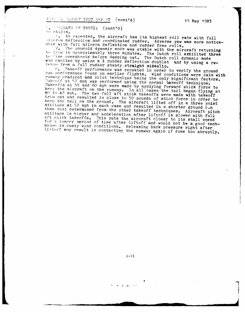
P T (cont'd) lq May 1983
'" .U L, (; TESTS: (cont'd)r" Otfi 139.
. At expected, the aircraft has its highest roll rate with fulli ir'n deflection and coordinated rudder. Adverse yaw was more notice-hible with full aileron deflection and rudder free rolls.'. 'he phugoid dynamic mode was stable with the aircraft returningtrir in approximately three minutes. The Dutch roll exhibited threetL live overshoots before damping out. The Dutch roll dynamic modewaS excited by using a 4 rudder deflection doublet and by using a re-
]e- from a full rudder steady straight sideslip.. rakenff performance was repeated in order to verify the groundrun perf ormance found on earlier flights. Wind conditions were calm withruriwv 1gradient and pilot technique being the only significant factors.Ik,eoff at '2 mph was performed using the normal takeoff technique.Takeoff's at 55 and 60 mph were made by applying forward stick force tokeoj the aircraft on the runway. In all cases the tail began flying at4() to 42 mph. The two full aft stick takeoffs were made with takeofftrim net and resulted in close to 50 pounds of stick force in order tokep, the tail on the ground. The aircraft lifted off in a three pointattitude at 52 mph in each case and resulted in a shorter ground runthan that determined from the other takeoff techniques. Aircraft pitchattitude is higher and acceleration after liftoff is slower with fullaft ,;tick takeoffs. This puts the aircraft closer to its stall speedfor :t lontger period of time after liftoff and would not be a good tech-nique in gusty wind conditions. Releasing back pressure right afterIiftoff mny result in contacting the runway again if done too abruptly.
:)-15
6 2
INITIAL FLIGHT TEST REPORT7 G2-7N3A
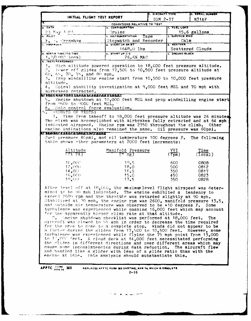
CONDITIONS RELATIVE TO TESTa. ATI CONIGURATION .- UL3X
1 ' __ ru ise 15.6 gallonsh. PILOT I. INSTRUMENTATION Tape 1. SURFACE WIND
1%*L'('lshrlw ____ topwatch and Recorder CalmR% oR~PvrI if START UP OR WT k ETE
____ 1648.0 lbs Scattered Cloudsd. SO6RIIE TIME/TO TIME h. START UP C G 1. GROUND BLOCK
1 *2/ 12 ocal 26.6% MAC4. TESTS PFRFORMEO
1. llifrh altitude powered operation to 18,000 feet pressure altitude.2 * 'wer off glides from 17,500 to 10,500 feet preosure altitude atC , 7n, 7f), and 80 mph.
5u' prsu4opl andn nile stemrtre 1050 detee F.00 Thet following
Ate 'lides- ondffern dirR(),tetions anover dlifret areas whic mayer
2(00r rpme acnistee uringq ata readductighel airrf flewphand hbind7ed lik a) mlidte wnihls fgie r260matifol than ur with.theurlnc. a s idexpetienalysi hould psstantia00fte thi. myacon
AfTr thRM appre5 l REPLACES A liT b rate at5 ONhIMt MAalt Mit udOe.APR iin shtoncekitwsprfre4t1,O et h
was~~~~~~~~D 6Iwdt )mhinodrt erae h ierqie
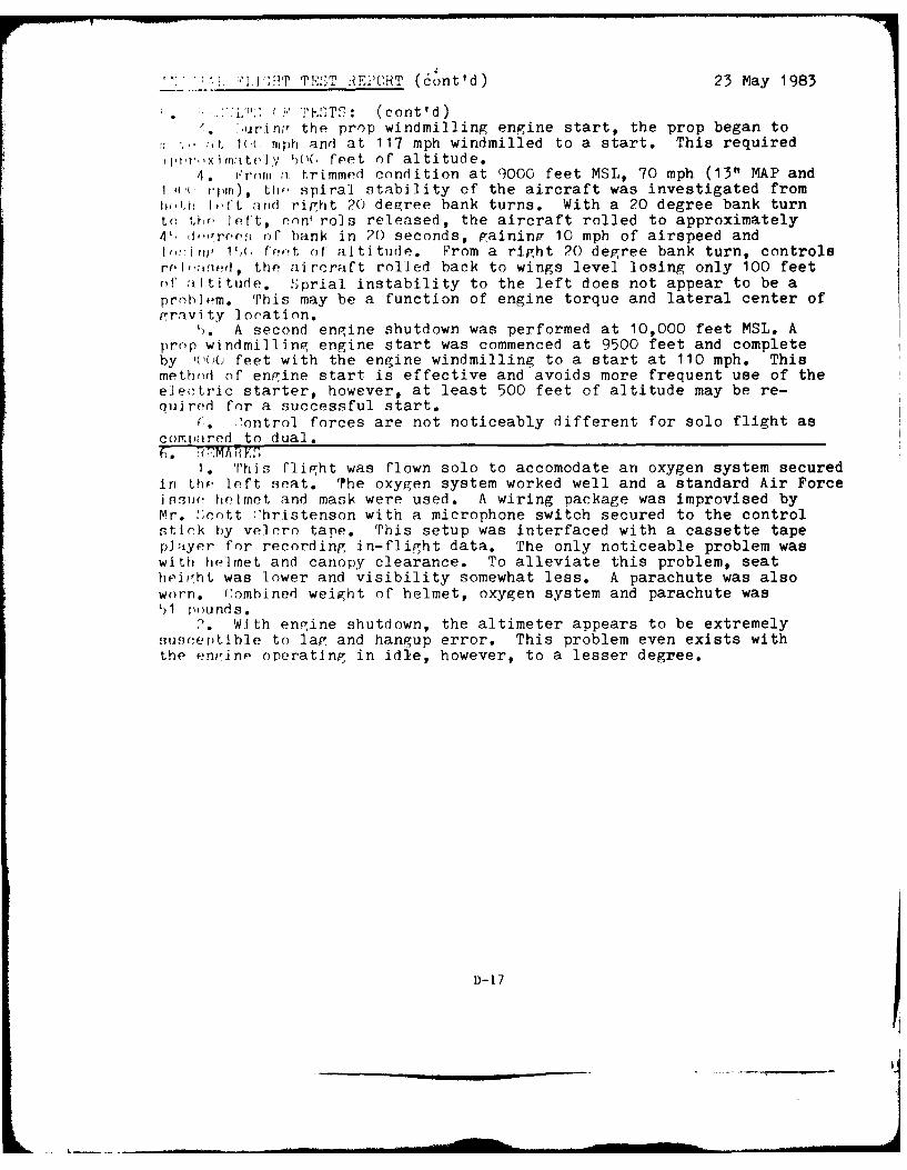
'.i. ;-'] , !T TEST R EPORT (6ont'd) 23 May 1983
.L", ES ' Tq: (cont'd). rir, the prop windmilling engine start, the prop began to
(., 1(( mph and at 117 mph windmilled to a start. This requiredppr.,xityvitely )()(, feet of altitude.
4. ,roim a trimmed condition at 9000 feet MSL, 70 mph (13" MAP and1 4(" rim), tho spiral stability of the aircraft was investigated frombih lItft arid right 20 degree bank turns. With a 20 degree bank turnto theo left, nn' rols released, the aircraft rolled to approximately4' ,Iiree r of hank in 20 seconds, gaining 10 mph of airspeed andI ,,iny 1Y', fe,,t of altitude. From a right 20 degree bank turn, controlsrel',:reeJ, the aircraft rolled back to wings level losing only 100 feetof altitude. Sprial instability to the left does not appear to be aproblem. This may be a function of engine torque and lateral center ofgravity loration.
(. A second engine shutdown was performed at 10,000 feet MSL. Aprop windmillinq engine start was commenced at 9500 feet and completeby (,()o feet with the engine windmilling to a start at 110 mph. Thismethod of engine start is effective and avoids more frequent use of theele(tric starter, however, at least 500 feet of altitude may be re-quired for a successful start.
(. ontrol forces are not noticeably different for solo flight ascomipired to dual.f. 1VMA fRK,"
1. 'his flight was flown solo to accomodate an oxygen system securedin the, left seat. The oxygen system worked well and a standard Air Forceisuoe helmet and mask were used. A wiring package was improvised byMr. ;cott Vhristenson with a microphone switch secured to the controlstick by velrro tape. This setup was interfaced with a cassette tapeplayer for recording in-flight data. The only noticeable problem waswith helmet and canopy clearance. To alleviate this problem, seatheiiht was lower and visibility somewhat less. A parachute was alsoworn. f!ombined weight of helmet, oxygen system and parachute wasL,1 I(undds.
2* With engine shutdown, the altimeter appears to be extremelysus'entlble to lap and hangup error. This problem even exists withthe enfinp operating in idle, however, to a lesser degree.
D-17
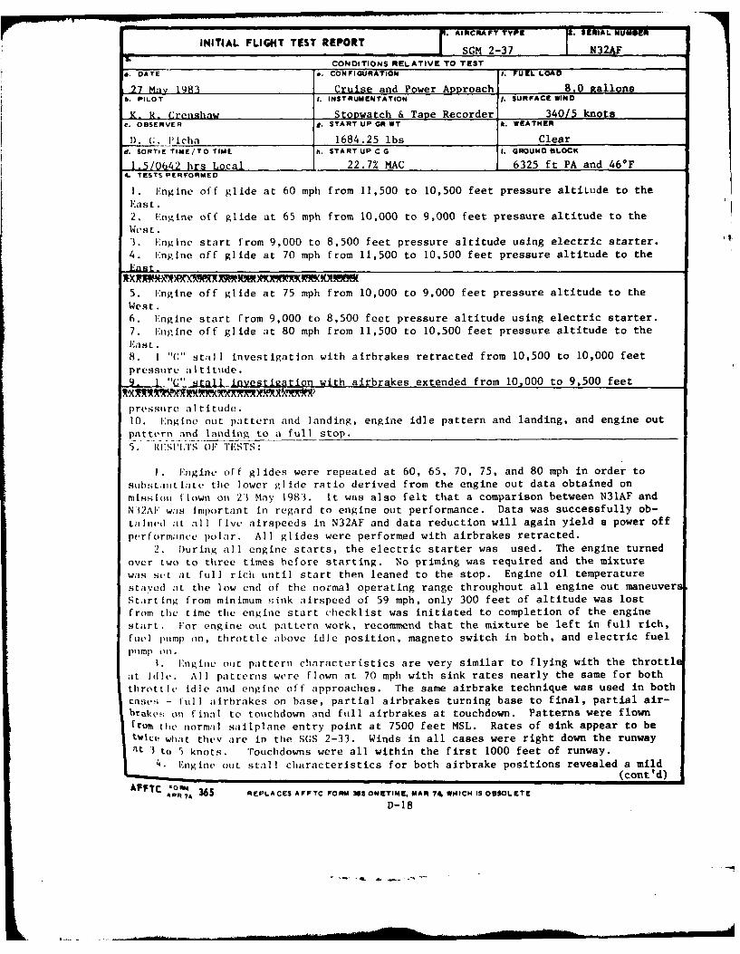
F. AIRCRAFT TY SEIAL N3iERINITIAL FLIGHT TEST REPORT SGM 2-37 N32"
CONDITIONS RELATIVE TO TESTa. DATE a. CONFIGURATION I. FUEL LOAD
27 May 1983 Crulse and Power Aproach 8.0 eallonsA. PILOT 1. INSTRUMENTATION j. SURFACE WIND
K. R- Crenshaw Stopwatch & Tape Recorder 340/5 knotsc. OBSERVER . START UP GR WT J. WEATHER
1). (;. Picha 1684.25 lbs Cleard. SORTIE TIME/TO TIME h. STARTUP CG I. GROUND BLOCK
1.5/0642 hrs Local 22.7% MAC 6325 ft PA and 46*F4. TESTS P ERFORMED
1. Engine off glide at 60 mph from 11,500 to 10,500 feet pressure altiLude to theEast.2. l'ngine off glide at 65 mph from 10,000 to 9,000 feet pressure altitude to theWest.3. Engine start from 9,000 to 8,500 feet pressure altitude using electric starter.4. Engine off glide at 70 mph from 11,500 to 10,500 feet pressure altitude to theEast.
5. Engine off glide at 75 mph from 10,000 to 9,000 feet pressure altitude to theWest.6. Engine start from 9,000 to 8,500 feet pressure altitude using electric starter.7. Engine off glide at 80 mph from 11,500 to 10,500 feet pressure altitude to theF'a st.
8. I "G" stall investigation with airbrakes retracted from 10,500 to 10,000 feetpressure altitude.9.- L "1 stall investication with airbrakes extended from 10,000 to 9,500 feet
pressure altitude.10. Engine out pattern and landing, engine idle pattern and landing, and engine outpattern and landing to a full stop.
5 I. f tIl'S 01F TISTS
I. Engine off glides were repeated at 60, 65, 70, 75, and 80 mph in order toSIstli¢til;Lte tile lower glide ratio derived from the engine out data obtained onmissliol flown oil 23 May 1983. It was also felt that a comparison between N31AF andN12AF was Important in regard to engine out performance. Data was successfully ob-tallned it all five airspeeds in N32AF and data reduction will again yield a power offperformance polar. All glides were performed with airbrakes retracted.
2. During all engine starts, the electric starter was used. The engine turnedover two to three times before starting. No priming was required and the mixturewas sut at full rich until start then leaned to the stop. Engine oil temperaturestaved at the low end of the normal operating range throughout all engine out maneuversStarting from minimum Pink airspeed of 59 mph, only 300 feet of altitude was lostfrom the time the engine start checklist was initiated to completion of the enginestart. For engine out pattern work, recommend that the mixture be left in full rich,fuel pump on, throttle above idle position, magneto switch in both, and electric fuelpump olf.
1. Engine out pattern characteristics are very similar to flying with the throttleat idle. All patterns were flown at 70 mph with sink rates nearly the same for boththrottle Idle and engine off approaches. The same airbrake technique was used in bothcases - full aiirbrakes on base, partial airbrakes turning base to final, partial air-brake on final to touchdown and full airbrakes at touchdown. Patterns were flownfrom the normal sailplane entry point at 7500 feet MSL. Rates of sink appear to betw'ice wharit they are in the SGS 2-33. Winds in all cases were right down the runway
t 3 to 5 knots. Touchdowns were all within the first 1000 feet of runway.
4. Engine out stall characteristics for both airbrake positions revealed a mild(cont 'd)
AFIC A"oAP7 365 REPLACES AFFTC FORM 368 ONETIME. MAR 74 WHICH IS OBSOLETE
D-18
t. .. . . . . ... I ... .. -- . .. Il I I I I . ... . -.. . . - -.- I II I ,~ ~
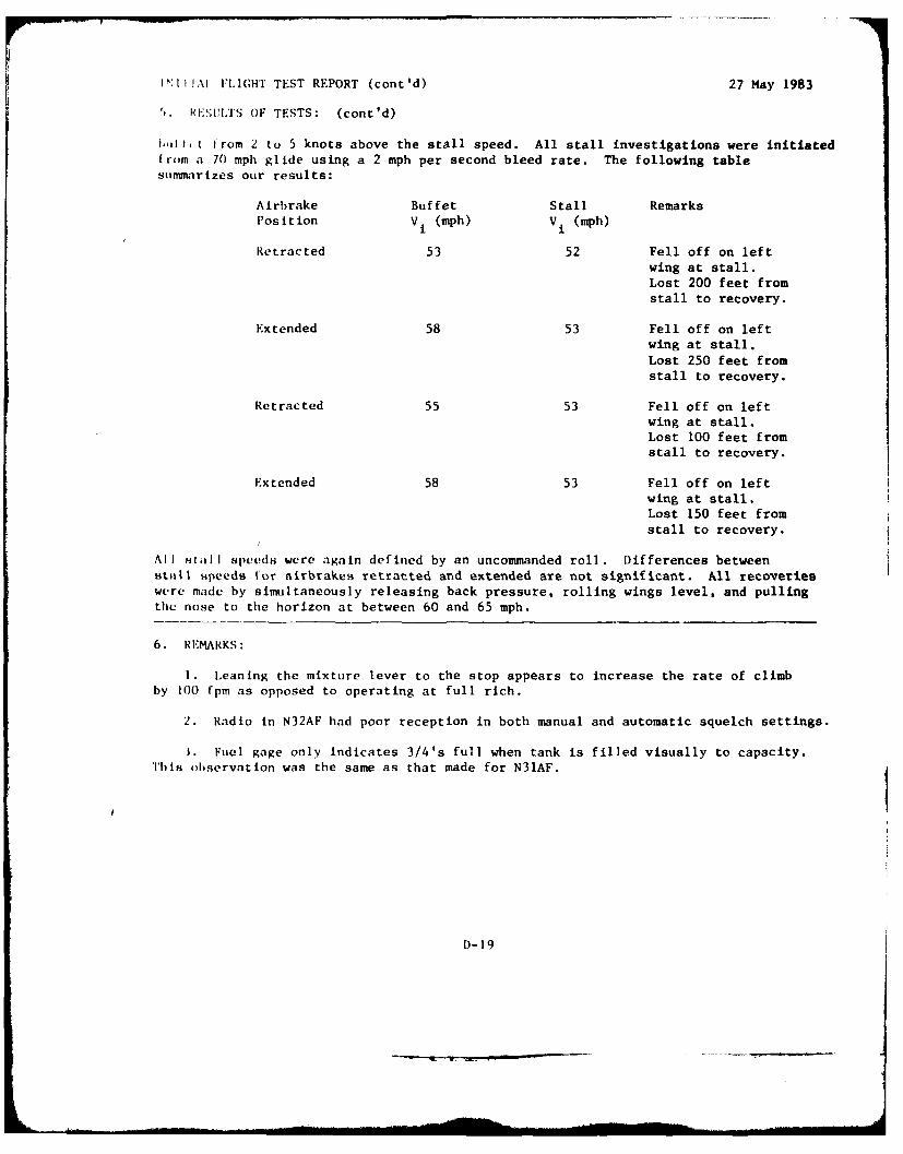
N:ti!,1 'I. ICHT TEST REPORT (cont'd) 27 May 1983
5. iHES(UILS OF TESTS: (cont'd)
1,, ft from 2 to 5 knots above the stall speed. All stall investigations were initiatedfrom a 70 mph glide using a 2 mph per second bleed rate. The following tablesummarizes our results:
Airbrake Buffet Stall RemarksPosition Vi (mph) V i (mph)
Retracted 53 52 Fell off on leftwing at stall.Lost 200 feet fromstall to recovery.
Extended 58 53 Fell off on leftwing at stall.Lost 250 feet fromstall to recovery.
Retracted 55 53 Fell off on leftwing at stall.Lost 100 feet fromstall to recovery.
Extended 58 53 Fell off on leftwing at stall.Lost 150 feet from
stall to recovery.
All H8iII speUdH were again defined by an uncommanded roll. Differences betweenutall speeds tor airbrakes retracted and extended are not significant. All recoverieswere made by simultaneously releasing back pressure, rolling wings level, and pullingthe nose to the horizon at between 60 and 65 mph.
6. REMARKS:
I. Leaning the mixture lever to the stop appears to increase the rate of climbby 100 fpm as opposed to operating at full rich.
2. Radio in N32AF had poor reception in both manual and automatic squelch settings.
1. Fuel gage only indicates 3/4's full when tank is filled visually to capacity.This observation was the same as that made for N31AF.