Page 1
University of Nebraska - LincolnDigitalCommons@University of Nebraska - LincolnStudent Research and Creative Activity in Theatreand Film Theatre and Film, Johnny Carson School of
5-2018
AVENUE Q: AN ENDEAVOR IN TECHNICALDIRECTIONBrendan Greene-WalshUniversity of Nebraska - Lincoln, [email protected]
Follow this and additional works at: https://digitalcommons.unl.edu/theaterstudent
Part of the Fine Arts Commons, and the Other Theatre and Performance Studies Commons
This Article is brought to you for free and open access by the Theatre and Film, Johnny Carson School of at DigitalCommons@University of Nebraska -Lincoln. It has been accepted for inclusion in Student Research and Creative Activity in Theatre and Film by an authorized administrator ofDigitalCommons@University of Nebraska - Lincoln.
Greene-Walsh, Brendan, "AVENUE Q: AN ENDEAVOR IN TECHNICAL DIRECTION" (2018). Student Research and CreativeActivity in Theatre and Film. 33.https://digitalcommons.unl.edu/theaterstudent/33
Page 2
AVENUE Q:
AN ENDEAVOR IN TECHNICAL DIRECTION
by
Brendan Robert Greene-Walsh
A THESIS
Presented to the Faculty of
The Graduate College at the University of Nebraska
In Partial Fulfillment of Requirements
For the Degree of Master of Fine Arts
Major: Theatre Arts
Under the Supervision of Professor Mitchell L. Critel
Lincoln, Nebraska
May, 2018
Page 3
Avenue Q:
An Endeavor in Technical Direction
Brendan Robert Greene-Walsh, M. F. A.
University of Nebraska, 2018
Advisor: Mitchell L. Critel
The Johnny Carson School of Theatre and Film at the University of Nebraska
began its spring semester of the 2017-2018 season with a production of Avenue Q.
Director Andy Park staged this production in the Johnny Carson Studio at the Lied
Center on the University of Nebraska campus. My role in the production was that of
technical director. The responsibilities of the technical director include budgeting of
departmental resources, money and labor, engineering and construction of all scenic
elements, maintaining a safe working environment, creating and adhering to a timely
build schedule, maintaining the designer’s aesthetic vision throughout, the
transportation and installation of all scenic elements to the performance space and
removal of all elements following the completion of the production.
This thesis details the process necessary to take a conceptual design and put it
into a working reality within the confines of budget, time and available skill. Following
the conclusion of this thesis is a series of appendices to support the written
information.
Page 4
iii
Table of Contents
Chapter 1: Introduction 1
Chapter 2: Preproduction 3
Chapter 3: Construction 11
Chapter 4: Load In 17
Chapter 5: Technical Rehearsals 22
Chapter 6: Performances 27
Chapter 7: Strike 28
Chapter 8: Budgeting 30
Chapter 9: Conclusion 31
Appendix A: Designer Reference Materials 33
Appendix B: Technical Drafting 36
Appendix C: Documentation 66
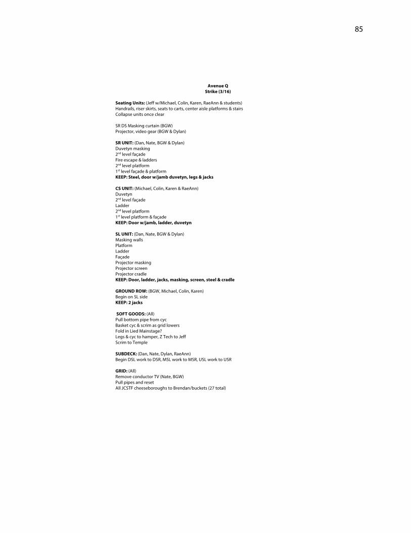
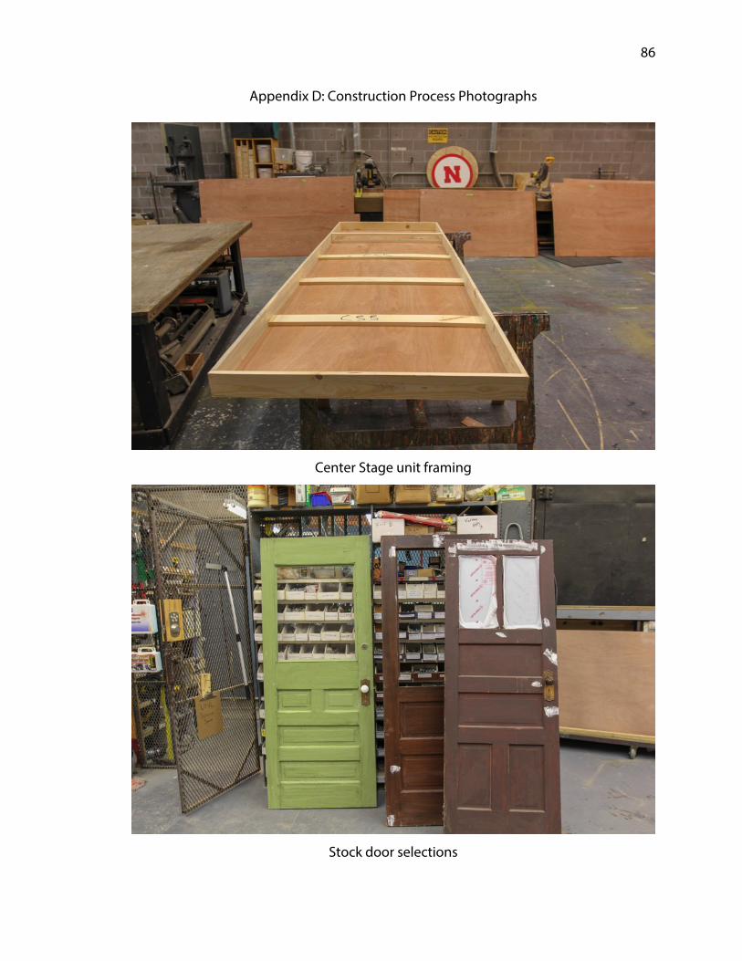
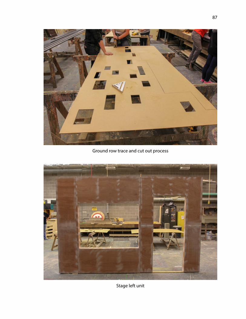
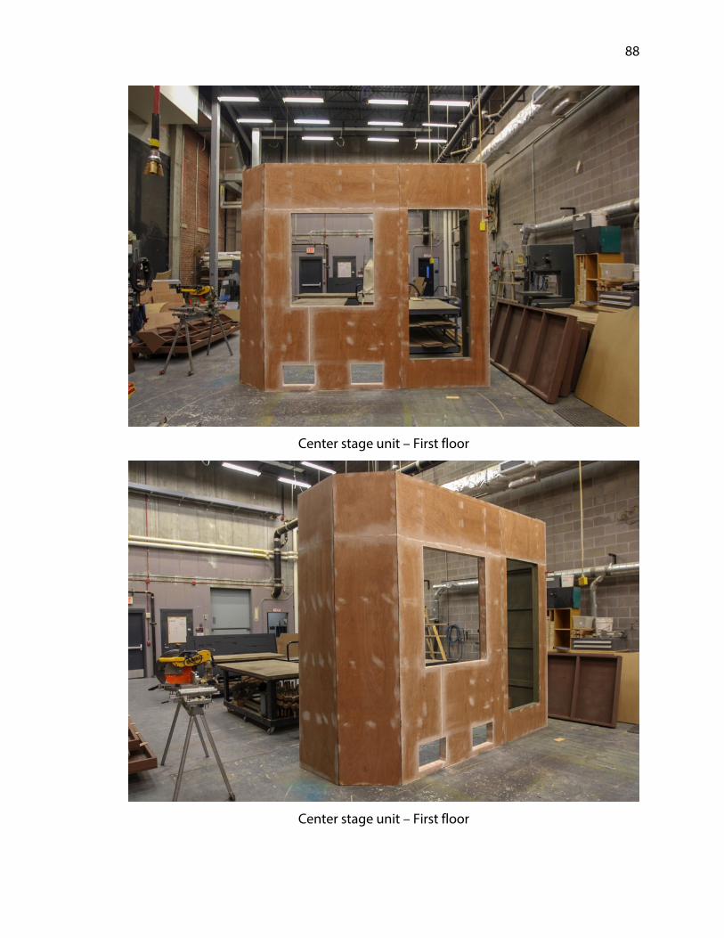
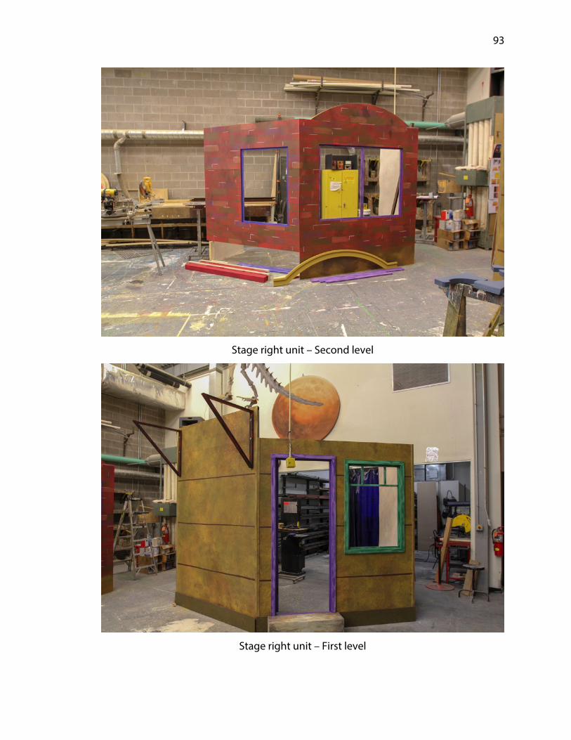
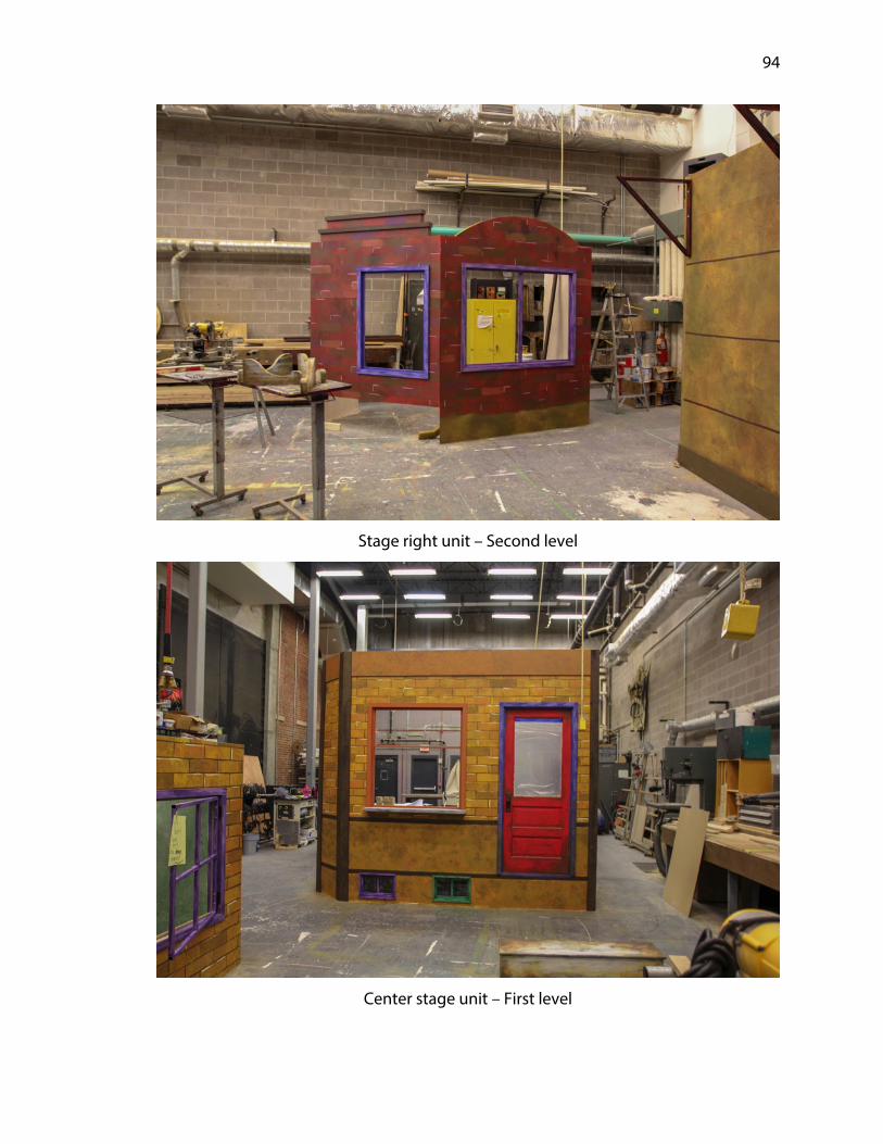
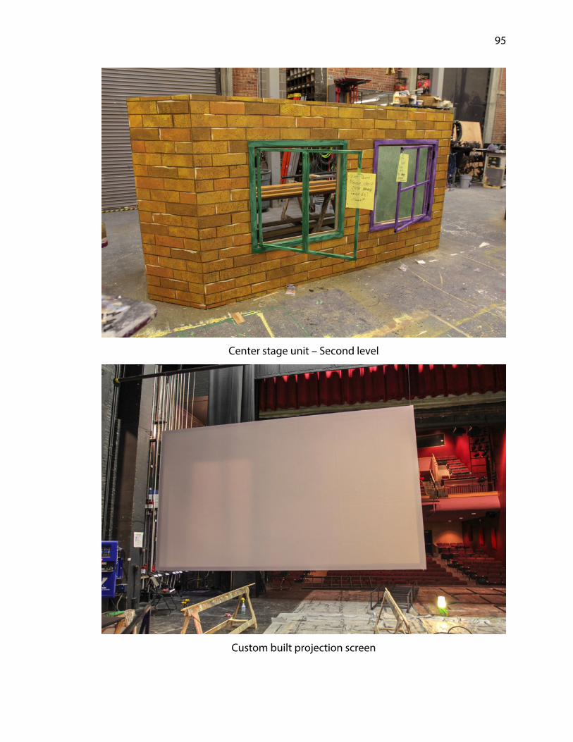
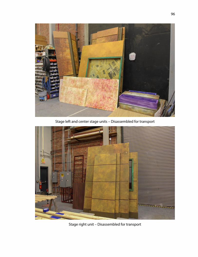
Appendix D: Construction Process Photographs 86
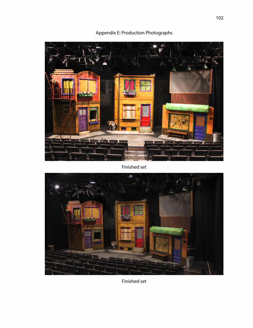
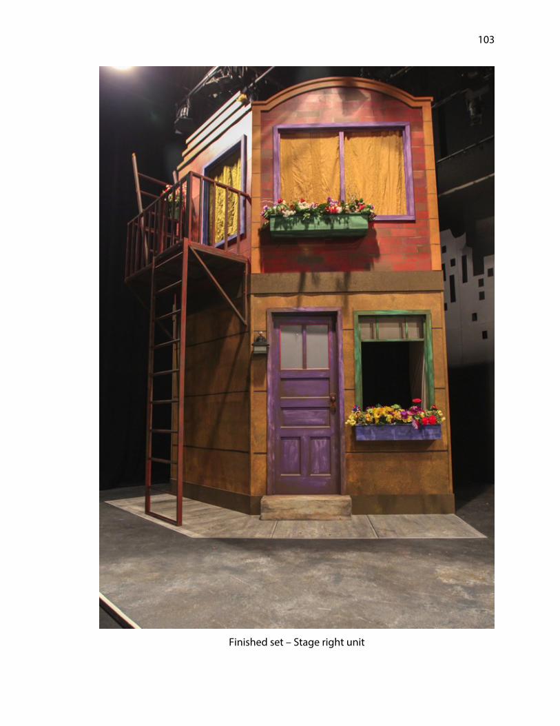
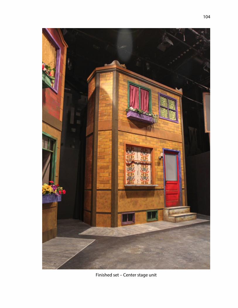
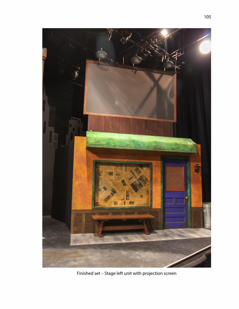
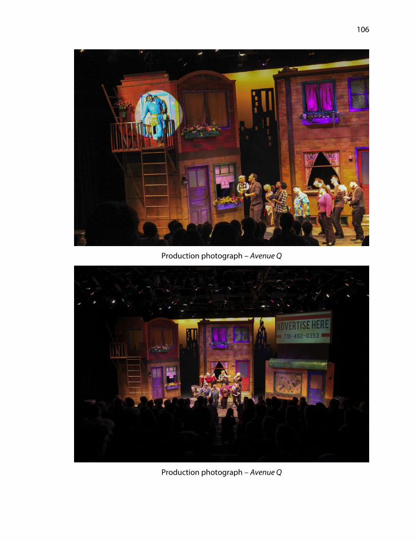
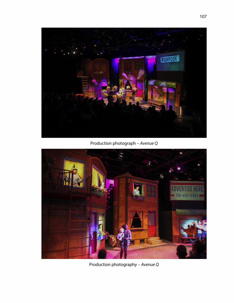
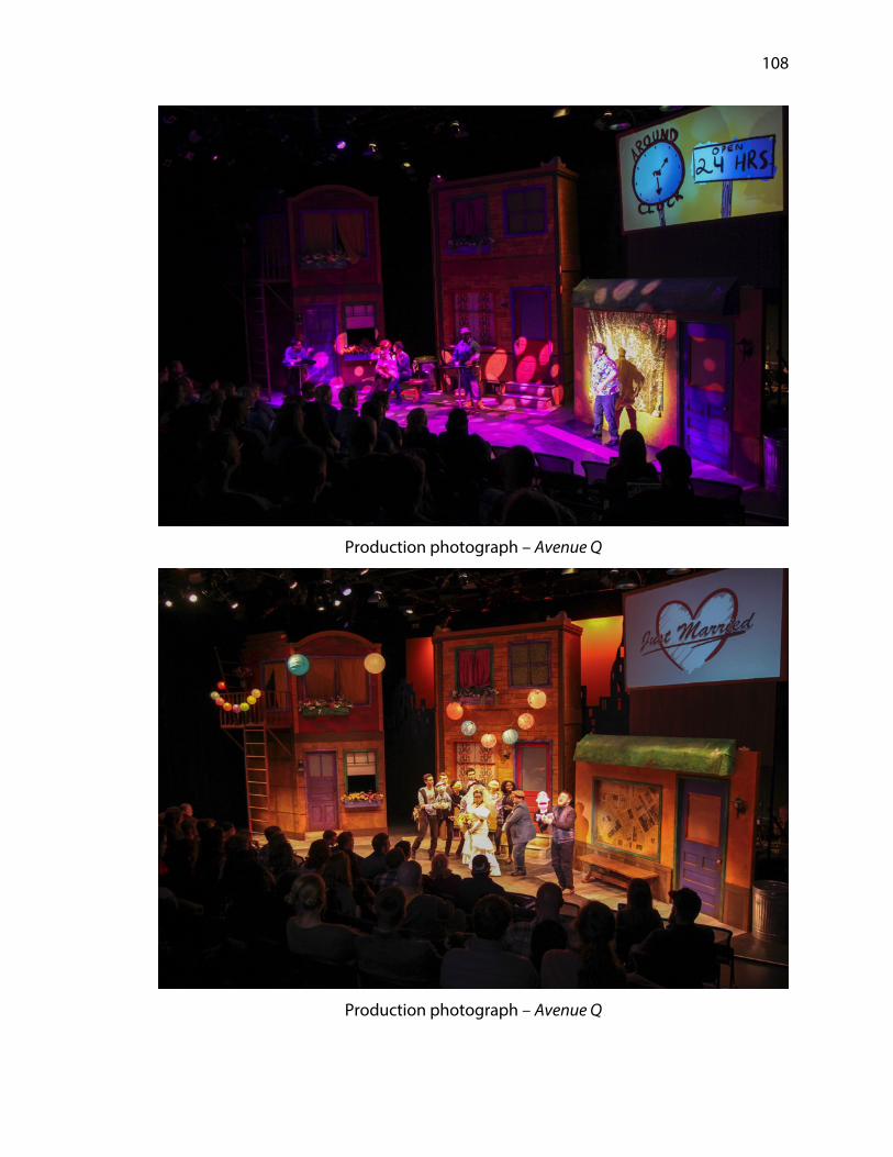
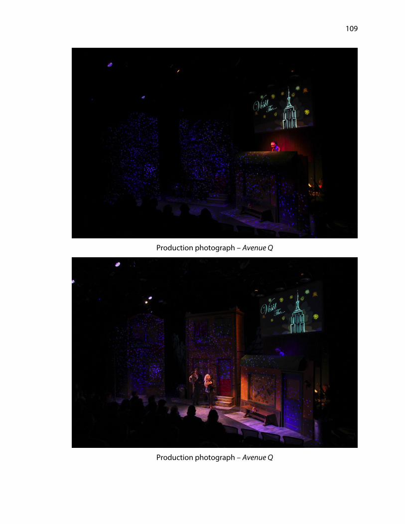
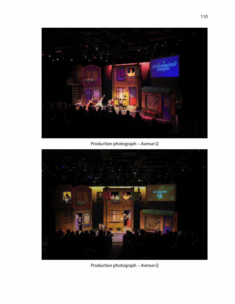
Appendix E: Production Photographs 102
Page 5
1
Chapter 1: Introduction
The Johnny Carson School of Theatre and Film began the spring
semester of the 2017-2018 season with a production of Avenue Q. The production took
place in the Johnny Carson Studio Theatre located in the Lied Center on the campus of
the University of Nebraska. The production officially opened on March 2, 2018 and
closed on March 16, 2018 with a total of fifteen performances. The production team
included Andy Park (director), Jessica Thompson (scenic designer), Jamie Bullins
(costume designer), Laurel Shoemaker (lighting designer) and Emily Callahan (sound
designer). I received the assignment of technical director for the production during
the spring of 2017.
Avenue Q was written by Robert Lopez and Jeff Marx with book by Jeff Whitty. It
opened on Broadway in 2003 at the John Golden Theatre, where it won three Tony
Awards. The musical is a comedic satire on the maturation process of becoming an
adult and having to leave behind the false realities ingrained in the heads of
adolescents growing up. The production incorporates puppets, puppeteers and
human actors in a not-so-subtle imitation of the world created for Sesame Street. This
world, however, is firmly rooted in modern day trials and tribulations and the realities
that begin to set in once youth reaches adulthood. The show primarily follows the life
of Princeton, a recent college graduate who has found himself with no money, no
applicable skills and no idea how to navigate this newfound and rather harsh world.
The audience watches as Princeton traverses his way through romance and
Page 6
2
heartbreak, the extremes of both good and bad advice, and general despair, with
musical comedy relief underscoring everything.
This thesis is intended as a detailed overview of the process of taking the
artistic and aesthetic goals of the production team as a whole and bringing them into
a finite and produced reality. The main objective of the technical director follows
closely to the work of the scenic designer. The ultimate goal of the technical director is
to maintain the scenic designer’s artistic and aesthetic vision from start to finish. The
technical director accomplishes this process through a variety of means. Primary
responsibilities include accurate budgeting of time, resources and materials,
engineering and construction of scenic elements, implementing schedules to allow
successful completion, maintaining a safe working environment throughout and
maintaining effective communication with all interdepartmental staff.
This production had a working budget of only $3,500.00, an amount which was
to cover all major scenic elements as well as all paint supplies. We received a six-week
window for the build schedule with three days available to pack the set into a box
truck and transport it to the performance space and install. The major components of
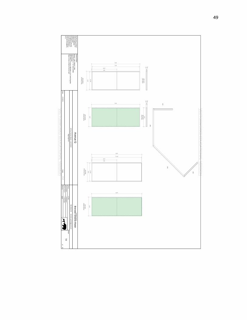
the design included two buildings façades, each with a second level, a third building
façade with a standing level above it, a custom projection screen, a full stage
silhouetted ground row as well as a full stage sub-deck to install the units atop.
Page 7
3
Chapter 2: Preproduction
Design meetings for Avenue Q began in September of 2017 with the design
team and director discussing the practical needs for the production. While the
technical director is not required to attend design meetings, my personal preference is
to be involved as early in the process as possible. I view my role in these meetings as
being a general observer of ideas and as a sounding board should any concerns arise.
This level of early involvement also provides a cursory background on why and how
design choices are being made and their intended effect. A few particularly notable
revelations from these meetings were the use of a live, six piece band on stage, the use
of projections throughout, the lighting designer’s interest in utilizing spot lights in a
performance space that did not naturally accommodate their usage and the growing
interest of the scenic designer to incorporate puppet-like functions into the set itself,
rendering the set itself as a giant puppet.
While none of these revelations fell solely under my purview, I felt it in the best
interests of the production as a whole to begin investigating some solutions. Due to
the fact that the Johnny Carson Studio is not located in the building that houses the
theatre department (the Temple Building), my working knowledge of the space was
far less familiar than with the other performance spaces in the Temple Building. As
such, I scheduled a walkthrough of the space with Dan Stratman, the director of
production at the Lied Center. The walkthrough was an informal event but afforded
me the time to see the space without any scenic elements installed, to inspect the
seating units that we would be utilizing and to take a few field measurements to
Page 8
4
ensure that the technical drafting of the building from which we were working was
accurate enough to avoid significant obstacles as we proceeded. During this meeting I
mentioned to Stratman that we were thinking of methods which might best
incorporate the spotlights at the rear of seating units. Stratman mentioned that the
Glenn Korff School of Music owned some scaffolding units that could potentially work,
as they had built in walk through openings so that we could maintain proper fire code
egress. I conveyed this information to the production team and we determined that
the lighting department would contact the School of Music to inquire about the
aforementioned scaffolding’s size and potential usage.
The design meetings shifted focus to become production meetings allowing
the facilitation of the production to begin to take shape while respective designers
were fine-tuning their work. During these meetings it was evident that a challenging
aspect of the production was growing in scale and concern and that was the use of
projections. While the Johnny Carson School of Theatre and Film has some stock of
video equipment, it is incredibly limited. There was also a noteworthy concern with
where responsibilities fell for not only sourcing the necessary equipment and its setup,
but also who would be responsible for the creation of the content. Fortunately, two
undergraduate students in the film department, Michaela Wadzinski and Ethan
Grafton, were willing to take on the task of content creation under the supervision of
faculty advisor Steve Kolbe.
With half of the matter solved, the responsibility of the technical aspect of
projection use was still batted around the room with no one department looking to
claim ownership. The particular challenge of using projections in Carson School
Page 9
5
productions lies in the absence of one person on faculty or staff who has expertise
enough to answer difficult questions concerning the technical needs and
requirements of equipment. Before frustrations could grow any further, I took this
responsibility upon myself. With base working knowledge of projections I suggested
that we utilize a rear projection screen to minimize the amount of ambient light with
the hope to have a bright enough image for the audience. Based on the initial working
ground plan from the scenic designer, there was slightly more than five feet of space
behind a screen that was roughly ten feet by six feet. Kolbe recommended that we aim
to keep the aspect ratio at 16:9 for video content’s sake. I then began research into the
throw angle of projector lenses, potential necessary lumen output, resolution and cost
of procurement.
The first component I needed to understand was how the throw of the lens
dictated the distance away from the screen necessary to create the intended
projection size. Throw ratio is expressed in a numerical ratio; for example a lens with a
throw ratio of 1.5:1 means that for every one foot of screen width you require, the
projector must been one and a half feet away. A projector with the throw ratio of 2.0:1
would require two feet of distance from the screen for a one foot wide image. With
this information I calculated that the absolute largest throw ratio for a lens for our
purposes would have to be in the 0.6:1 range but hopefully shorter than that, 0.5:1
would be ideal. This throw ratio is classified as a short throw lens. Having working
knowledge of the JCSTF projection equipment stock, I was less than optimistic that we
would have anything remotely close. A conversation with the house electrician Kathy
Turner confirmed my suspicions. Most projectors that the department owns are long
Page 10
6
throw in the range of 3.9-7.3:1. The shortest throw lens in stock was a 1.5-2.24:1, which
was not going to function for our needs.
The next line of inquiry led me to the Hixson-Lied College of Fine and
Performing Arts Information and Technology Services. David Bagby, the manager of IT
Services, informed me that unfortunately the college owned no projectors with a lens
throw within the range that I was searching. Bagby did however say that there was a
portable rear projection screen available that I could borrow for testing. Half of what I
needed was better than nothing at all. Broadening the search sent me in two different
directions. I first contacted Dog and Pony Productions, an audio/video rental company
based in Omaha, Nebraska. Dog and Pony Productions had a projector in stock that
could swap lenses in order to accommodate my needs, but they did not own said lens.
Dog and Pony could rent it from another company and then sub-rent it for the
production. While it was a relief finally to find some potential answers, that relief was
fleeting: the rental price came in at nearly $5,000.00 for the run of the production.
Considering the rental price was $1,500.00 beyond the scope of the entire scenic
budget, it was quickly evident that renting it would not be a feasible solution.
I subsequently contacted William Van Deest, my undergraduate advisor and
the theatre coordinator at Creighton University in Omaha. I recalled using projections
on a few shows during my years at Creighton, but I had no knowledge of what was in
their current inventory. Van Deest confirmed that they owned two ultra-short throw
projectors and that I could borrow one to test and see if it would suit our needs. Now
with both a borrowed projector and a borrowed screen I moved forward into the
testing phase. On December 14th I conducted a video test setup on the main stage of
Page 11
7
Howell Theatre in the Temple Building. I opted to use this space due to having
conventional theatrical lighting hung that I could utilize to gauge ambient light
bounce that would be likely during production. Invited to the test were Jessica
Thompson, Laurel Shoemaker and Andy Park, as well as JD Madsen (Professor of
Scenic Design) and Mitchell L. Critel (Professor of Technical Direction).
The test was successful in that we were able to project an image from very
short distance from the rear of the screen and that it was visible through ambient
theatrical light at a distance of nearly fifty feet away. Though the team agreed that the
projector would fit the needs of the production, I was left wanting a better option. The
image degradation beyond eight feet in width, the lower resolution and the low
lumen output gave me cause for concern. I again contacted Van Deest and discussed
my misgivings. He agreed and mentioned that he may have another option through
an audio/visual specialist whom he contracts for work. Two weeks following I had a
second option to test, one that was newer and smaller with a higher resolution and
brighter lumen output. Within moments of testing the second projector my concerns
were put to rest. It was evident that this projector would be capable of fulfilling the
needs of the production, and being able to borrow the projector at no cost was just as
big of a bonus.
With the business of projections more or less put to bed, I was now able to
focus on my primary concern, the scenic design. The initial design packet was due on
December 8th for cost analysis with my costing due on December 15th. I received the
packet on December 11th and quickly got to work. The idea of creating building
structures that mimicked puppet actions meant that entire walls were able to pivot
Page 12
8
and slide open and close. Such mimicry, while interesting, posed a significant
challenge in the eventual engineering of those components. Most often, when large
scale movement of scenic elements is involved in a design, the cost begins to rise in
lockstep. Another considerable element of the initial design that was going to add to
building costs was a cantilevered second level to house the entire band so they were
not taking up a significant portion of the main playing space for the actors. Over four
days I worked through the multitude of scenic elements. My process of cost analysis
involves a component of pre-engineering where I began to determine how structures
must be built in order to determine materials and quantities.
I completed the cost analysis before meeting with Thompson, Park and Critel
on December 15th. The result of the analysis was that the initial design was roughly
$8,500.00 over budget. Quite candidly, I would say this surprised no one in the room.
In order to construct the main scenic elements and have them resilient enough for
transport to another theatre, I opted for an all steel frame construction. This was
particularly necessary for the units that opened and closed for durability’s sake, as well
as the cantilevered band platform. Professor Critel and I offered suggestions to
Thompson about minimizing some of the intricacies of the design without losing the
aesthetic qualities. One of the main suggestions was that the functionality of the set as
a puppet be discarded in place of a more traditional façade to the buildings. Another
suggestion was to design a way so that the band platform was able to have more
vertical support, thus requiring less heavy duty structural steel for construction. At the
conclusion of the meeting we determined that Thompson would have five days for
revisions, after which I would embark on another cost analysis. This delay pushed
Page 13
9
revisions and re-costing into winter break, a period we had earmarked for the
engineering process of the production.
Thompson began sending gradual revisions starting on December 20th with a
completed packet arriving December 23rd. It became evident that she was holding
onto the idea that the set function as a puppet, albeit on a lesser scale. I completed the
subsequent cost analysis on December 24th, but the design still exceeded $4,000.00
beyond working budget. At this point I had to be very honest and insist on austerity: if
the design were going to be realized the idea of its puppet like functions would have
to expire. This was not easy for Thompson, nor me. I was truly excited by the concept
of the design. Avenue Q has been produced without such machinations time and time
again, but this was an opportunity to create an interesting take on what has become a
commonplace design. It was nevertheless unfeasible within the working budget.
Thompson set to work on another round of revisions which were more in line with a
redesign of the set, which I received on December 28th and began re-costing.
I completed the cost analysis of the redesigned set on December 29th, and
though still over budget, it was now within an allowable range that I felt could
become achievable. Major changes came from eliminating the puppet-like mechanics
of the buildings as well as moving the band to the upstage area of the main playing
space instead of housing them on a second level platform. I scheduled a phone
conversation with professor Critel to discuss how and where the design had changed
and to confer with him about the amount that it was currently over budget. I
suggested that lowering my contingency budget line (a cost reserved for unexpected
expenses), moving a few cost items from scenic to props and charging the cost of the
Page 14
10
custom built rear projection screen to a special effects cost line would allow the show
to be within budget. Critel agreed and we were able to proceed with the design,
without losing significant visual aesthetics from the intent of the original design.
On December 30th I began the engineering process in earnest and with a
quickened pace. Build on the set was slated to begin January 2, 2018 but I remained
doubtful about time sufficient to create enough working drafting for the shop to
begin by that date. The engineering process would take me the ensuing two weeks to
complete, working mostly during the evening or whenever not in class. The largest
downside to working through the costing and redesign process over winter break was
it had consumed all of the time earmarked to engineer the show effectively. This
process inevitably led to a few oversights on my part but thankfully nothing that was
insurmountable.
Page 15
11
Chapter 3: Construction
Construction of the show officially began on January 3, 2018, not too far off the
intended start date of the 2nd. Classes did not begin until January 8th, so during this
week the labor force consisted of fellow technical direction graduate students Daniel
D’Egnuff, Michael Strickland and me. I had my counterparts begin construction on the
sub-deck pieces we would have to build to accommodate the set within the
constraints of the Johnny Carson Studio. Any scenery utilized in the studio we had to
install atop a sub-deck of our own design and creation so that we could anchor down
set pieces to it. The studio has a battleship linoleum floor of which the Lied staff is very
protective, so protective indeed that a single screw hole into their floor came with a
repair bill of $100.00. At this point in the budget we were mindful to avoid such costly
mistakes. We completed construction of the sub-deck early the following week and
gave it to the paint shop.
Classes for the 2018 spring semester began January 8th, meaning that we would
soon have the undergraduate student force back in the shop to assist in the build
process. The scene shop employs four undergraduate workers: first year students
Karen Husband and RaeAnn McCoy and second year students Colin Falk and Dylan
Spilinek. Professor Critel assigned Spilinek the task of master carpenter for the show.
These students are vital in the function of the shop, whether it is taking on individual
projects or utilizing other students to complete larger projects. The students in the
other pool of workers come from lab components in the Intro to Theatre class (THEA
112) or the Technical Theatre Practice course (THEA 201). The total expected number
Page 16
12
of students for the semester would reach around 55. These students, however, needed
to go through safety orientation before being allowed to begin their lab hours, so their
anticipated start date was another week away.
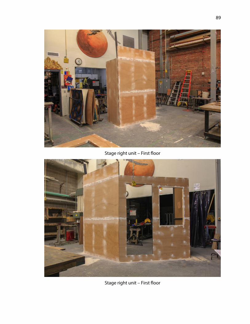
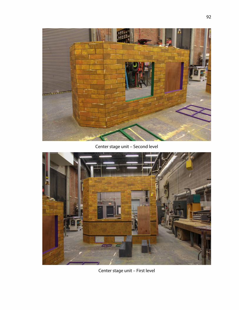
During the first week of classes the four shop employees along with the
graduate students began work on the façades of the center stage unit and the stage
left unit. The center stage unit split into two sections, a first and second floor in order
for ease of construction, but also for transportation out of the building and into the
performance space. Each level of the center stage unit consisted of five walls, while the
stage left unit consisted of three walls. Work on these units continued into the
following week and we completed work on them January 18th, after which we handed
off to the paint shop. The shop had been operating at a substantial pace up to this
point, and I feared that the introduction of lab students could potentially begin to bog
down that progress. This observation is by no means a knock on the lab students
coming in to work, but it is rooted in the reality that most, if not all of them, have little
to no prior experience working in a scene shop. And as an instructor of one of the
sections of THEA 201 I do not expect them to. Their lack of experience is the specific
reason for offering the course. That inexperience, however, means that they require
more time, careful consideration and considerable oversight as they begin working in
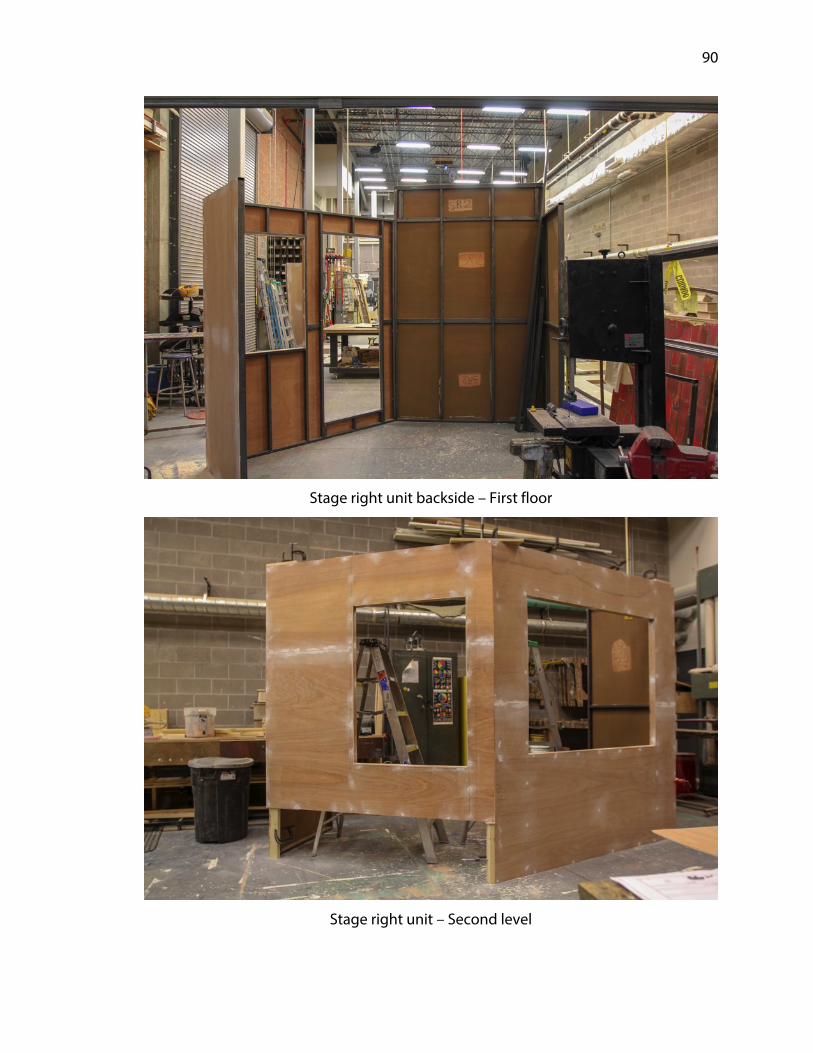
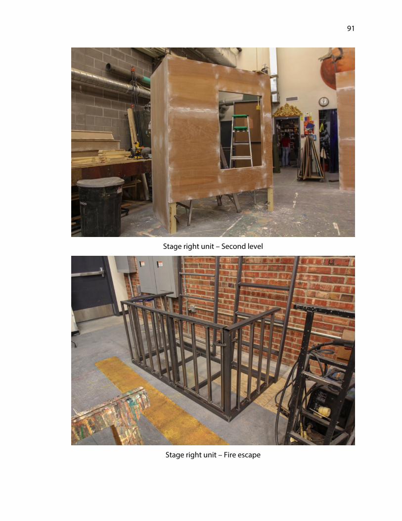
the shop. During this week a sizable order for steel arrived, which I planned to use for
construction of the stage right unit, the fire escape, the ships ladders used to access all
second levels, as well as the frame for the custom projection screen.
To my delectation, the overall progress and pace of the shop was functioning
well and it did not begin to slow with the addition of lab students. Their eagerness to
Page 17
13
hop in and their willingness to deal with some of the more mundane tasks kept the
build moving ahead. There was one day in particular where the assistant technical
director Daniel D’Egnuff stopped and forced me to take count of the number of
humans working in the shop. The total number was somewhere near twenty four,
which is generally more than double what the scene shop can typically accomodate.
Beginning the week of January 22nd I divided the specific workload in the shop.
The stage right unit façade, fire escape, ships ladders and projection screen were all
being fabricated from steel. The process of cutting, preparing and MIG (metal intert
gas) welding is beyond the experience of most student labor in the shop. I tasked
D’Egnuff as head of this operation with the assistance of master carpenter Dylan
Spilinek and shop employee Colin Falk. I thus divided the bulk of the lab students
amongst the paint shop and scene shop employee Karen Husband along with
graduate student Michael Strickland to begin work on the ground row. The ground
row was a silhouetted backdrop with the cityscape of New York City cut out of it. The
overall size was forty feet wide by almost eighteen feet tall.
Initially I had considered utilizing the Computer Numeric Controlled (CNC)
machine the Carson School owns to complete this task by loading the vector based
files and having the machine cut the profiles. After further evaluation I determined it
would be in the best interests of the shop and the lab students to utilize an alternative
method using a video projector to trace the images onto the material and then cut the
shapes out with hand power tools. While I am I staunch supporter of technology and
assisted in the research process for the grant for the CNC machine, I also firmly believe
that it would have been taking basic learning and an opportunity to work with tools
Page 18
14
away from the lab students. The accuracy would have been infinitely more precise had
the CNC been utilized, but for this particular application I felt it was far more important
to put tools into the hands of those that were there to learn, and learn how to use
them properly.
The work on these respective projects continued through the week and into
the following. During this week, however, it became apparent that the size and scope
of the design had put the shop at, if not beyond, capacity. In order to keep all build
projects moving forward the scene shop had effectively stretched out into every
available space within the Temple building. The shop itself was occupied with building
the ground row and painting the center stage unit. I was utilizing the studio theatre to
trace the ground row panels as well as using it as a full sized paint shop. The entire
Howell theatre stage had been taken over by the sub-deck which was waiting for its
final paint treatment after receiving a base coat of black. The stage left unit was
receiving final paint touches in the wagon house off stage left of Howell, and the
metal shop was beyond capacity. We were quickly running out of space, and that
crunch complicated the looming exigency of building the additional scenic units. It
was also around this time that I began to worry that the paint shop was not going to
complete their work successfully. They had spent three weeks working on samples to
this point and only the smallest unit in the show had been completed.
With two weeks left in the build schedule I worked to move all available hands
to assist with paint as I could afford. The remaining scenic elements to be built
included the platforms for the stage left, center stage and stage right units and a series
of jacks to support the ground row. The stage right unit was welded and ready to be
Page 19
15
covered in lauan for paint. The fire escape, the projection screen and trim for all units
were the final components to complete. The doors for the three units had come from
the stock that the Carson School owned. I asked Strickland to clean the doors up and
then create custom jambs so they could be installed into each unit. As D’Egnuff was
finishing up the welding projects I then had him turn his attention to cutting and
creating the trim work that would adorn all units. Most of the trim was simple in
nature, rectangular and without much detail work -- but there were a few pieces that
required some assembly to give depth and shape. The intention was to create a
labeling system for all of the trim before it went to paint so that it would be easily
discernible. It was my hope that the trim could be cut and built by February 9th so that
it could be painted over the weekend during the paint call that was scheduled for full
work days on the 10th and 11th. I spoke with the paint charge and explained the
labeling system and how it corresponded to the individual buildings.
The final week of build began February 12th and while there was a fair amount
of work ahead the end goal was certainly in sight. The bulk of the work during this
week was the detail work, those things that would help make the set look like a
cohesive finished product. This detail work included the installation of windows,
installation of all trim that could be done before transport, building capitals to adorn
the tops of the buildings, build the frame for and stretch the rear projection screen
material, building safety railings for the second levels of units, as well as building a
cradle to house the projector safely. There was a sense of excitement in the air among
the scene shop and staff. They had put a lot of work into the building process and
knowing that it would be installed the following week added encouragement to
Page 20
16
continue to power through. I had voiced my goal to the shop that by the afternoon of
Friday, February 16th, the bulk of the work would be done and that the crew could
begin to disassemble the major scenic units for transport the following Monday. We
met our goal head on when disassembly began at 3:00 PM that Friday. By 5:00 PM the
set pieces first in line for installation were neatly packed together and awaited load
out of the scene shop.
At this benchmark in the build process I was able to step back and take a
moment to reflect on the sheer amount of hard work and effort the crew had put in --
but I also reflected on a significant personal goal that I was unable to meet during the
build. It had been my intention to be able to assemble the set fully (sans sub-deck) on
the Howell stage in order to understand how exactly the second level units were
going to install together. I knew that there would be some amount of trouble-
shooting involved with this process and I wanted to experience the process within the
confines of our building in order to minimize any frustrations and to have a full
assortment of tools available as needed. This degree of preparation was simply not
feasible due to time and space constraints during the build process. It certainly did not
indicate a large failure on my end, it just meant that the trouble-shooting process
would have to happen in the Johnny Carson Studio during a very limited load-in
schedule.
Page 21
17
Chapter 4: Load In
For the process of transporting all technical elements of the production from
the Temple Building to the Johnny Carson Studio at the Lied Center the School rented
a twenty six foot box truck for the duration of February 18th to February 20th. In the
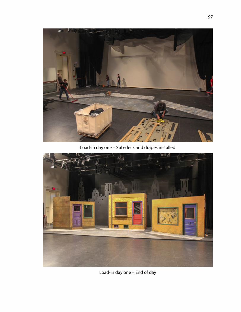
entertainment world, this is a process called “load-in”, during which the crew moves all
elements into the performance space and the installation can begin. Load-in officially
began on February 18th with the electrics crew taking the first day to hang all of their
lighting instruments and to begin focusing. This date also marked the time for the
sound department to hang their speaker plot. The Johnny Carson Studio utilizes a
motorized pipe grid that can be lowered via four cable drive winches. The intent was
that electrics could manage the majority of their hang on Sunday so that the grid was
only moved a total of one time, thus eliminating the number of times that they would
have to refocus instruments if the system had to be lowered again.
I was in attendance for a portion of this day as there were a number of ANSI
(American National Standards Institute) Schedule 40 steel pipes that required
installation to one end of the existing grid to accommodate the cyclorama and cyc
lights, the scrim, border, legs and other drapes and curtains. I gave lighting the first
couple hours of the day to begin their process before coming in with scene shop
supervisor Nate Rose to hang the pipe for scenic needs. During a stop by the studio I
noticed that there was a large projection screen hanging directly where the cyc was
supposed to hang, taking up about one foot of required depth. Speaking with Lied
production technician Jeff Koch I asked if it were possible to move the screen as it was
Page 22
18
not indicated on any of the technical drawings of the space. Koch thought it was a
possibility but it was a decision that required approval from his supervisor. I asked
Koch to keep me informed and began developing an alternative solution if it were not
feasible to move the screen. Koch later informed me that the screen would not be
movable. Rose and I proceeded with the alternate plan of moving the pipe that the cyc
hung on downstage one foot. The area of production that this change would most
affect was lighting if there was not sufficient room for their cyc lights to adequately
illuminate the cyc. After speaking with house electrician Kathy Turner and assistant
lighting designer Adam Jezl-Sikorski, they both thought the move would be
negligible. Rose and I continued to hang the remainder of the necessary pipes for soft
goods and scenic.
The scenic portion of the load in was scheduled for February 19th through the
21st, from 1:00 PM until 10:00 PM. These hours were extended beyond the typical
workday of the scene shop in order to have sufficient time to accomplish the task at
hand. The load-in schedule was particularly aggressive but optimistic. My hope was to
finish scenic load-in quickly and allow lighting as much time as possible in the space to
finish focusing and work on cueing. Due to the size of the design I determined that we
would require at least three trips with the box truck in order to transport all scenery to
the performance space before our truck rental expired on Tuesday the 20th. In order to
accomplish the timely use of the truck, the order in which the crew packed the truck
was of paramount concern to a successful load-in. Thus, the initial truck pack included
the first scenic elements that needed installation for the process to move
appropriately. This pack had four carts which contained components of the twenty
Page 23
19
four foot by forty seven foot sub-deck, the ground row, the jacks for the ground row
and the road box which contained all of the necessary tools for the scenic load-in.
The first items we needed to install were all of the soft goods: the cyc, scrim,
border and legs. These had to go in first because once the ground row was installed
the space they occupied would no longer be accessible. Once the soft goods were
hung, Koch, Critel, D’Egnuff and myself set the trim height on the motorized grid. This
process involved slight adjustments in height both up and down at six different points
throughout the space. Once the grid was set to its final trim height, the installation of
scenic elements could begin.
The sub-deck was the first and most obvious unit requiring installation,
because all of the other scenic units sat atop it. This process began a bit slowly but it
was important to get this component correct so that all of the other pieces in the
process would be able to be installed in their intended positions. While the sub-deck
was in process, I began spiking positions for the ground row and its support jacks for
installation. Crews were concurrently loading the second truck pack at the Temple
Building, with the first floor façades of all of the units, the masking unit for the
projection screen and all of the platforms and legs. While I installed the ground row,
the crew unloaded the second truck pack; meantime we installed the stage left unit
with its second level platform. Once the ground row was completed, my attention
turned to getting the center stage and stage right first floor façades installed followed
by their first and second level platforms.
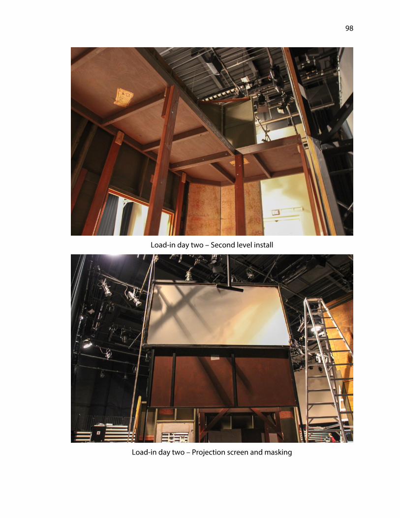
Day two of load in began with the third and final truck pack. The second level
façades of the stage right and center stage units we had purposely left behind to allow
Page 24
20
paint time to finish detail work as well as electrics time to finish running cables for the
light emitting diode (LED) tape. In addition to the second levels, the ships ladders, fire
escape, safety handrails, stair units, flower boxes, awning and projection screen were
loaded. Once the truck arrived at the performance space it was quickly unpacked and
work began installing the ships ladders to the stage left and center stage units while
the stage right second level façade was installed. During this period I added rigging
points to the grid of the studio to create hanging positions for the projection screen
and projector itself.
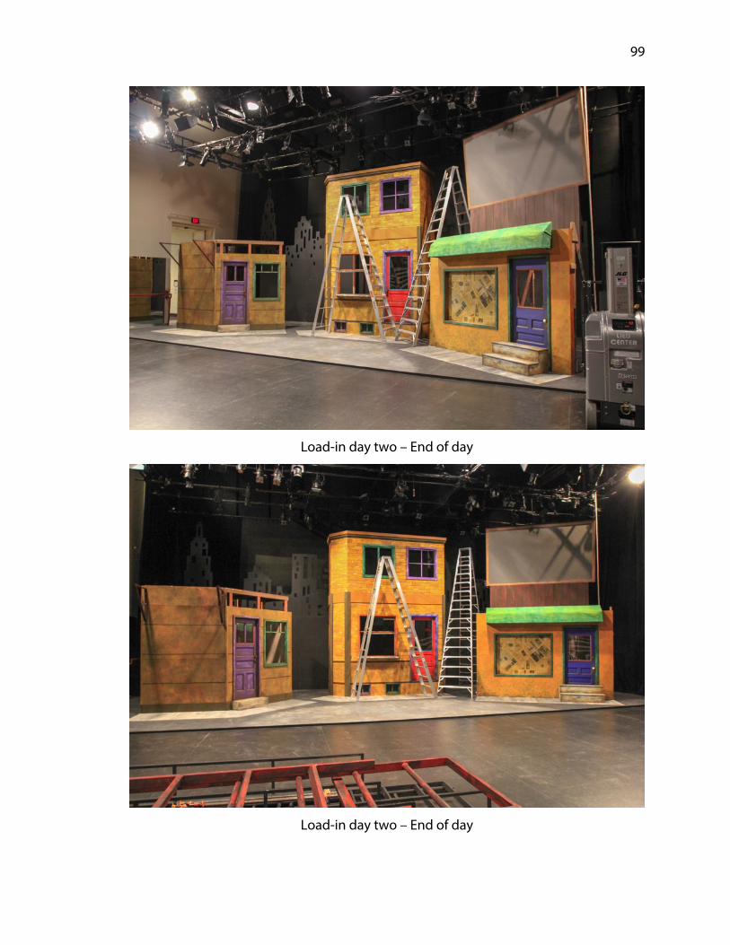
Following the completion of those elements the crew turned its attention to
installing the ships ladder on the stage right unit while adding the safety handrails to
all second levels. The safety handrails served a double purpose for the production.
First and foremost they were there to keep the actors on the second levels safe from
falling to the stage floor from a height of nearly ten feet. Their second purpose was to
provide the basic structure for black masking fabric, to prevent the audience from
seeing beyond the interior of the units when doors and windows were opened. The
addition of this masking was added rather late in the process and though I would
hesitate to call it an afterthought, in all reality an afterthought is it was. My solution
involved running cordage between vertical sticks of steel that were incorporated into
the safety handrail. Once the cordage was hung I draped black duvetyn (or
“commando cloth”, depending on which coast you live on) and safety pinned it
around the line. While I feel there could have been a more intentional masking device,
this fit the need of the production.
Page 25
21
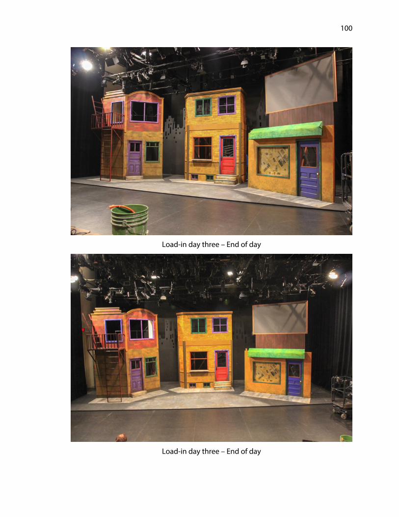
At the end of the third day of load-in we had installed all of the major scenic
elements without any major challenges. At that juncture, the scenic crew could not
return to the performance space for additional work until Friday, February 23rd to allow
lighting maximum time in the space to fine focus instruments and complete cue work.
However, Dylan Spilinek and I spent a few hours in the space on Thursday, February
22nd running cables for the projector as well as the video feeds of the conductor for the
cast and stage management and of the stage feed for the conductor.
Friday, February 23rd was the last working day before having cast on stage later
that evening. It was in the best interests of the production as a whole that some of the
smaller detail elements be in place so that the cast could begin working with them
and the set in order to become as comfortable as possible. The crew installed flower
boxes, tagged all masking curtains with white ribbon so that the cast understood
entrances and exits, they hung the last two masking legs, and they striped the set as a
whole with white gaff tape to avoid any instance in which someone could be caught
off guard while moving in the dark. The remaining trim that we could not install before
transport we now expedited during this time. Though some finishing details remained
uninstalled at this point, I was content with the state of the set heading into technical
rehearsals.
Page 26
22
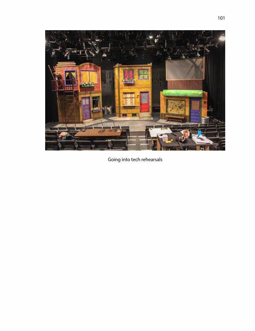
Chapter 5: Technical Rehearsals
The technical rehearsal schedule did not officially begin until February 24th, but
on the evening of the 23rd there was a blocking rehearsal which gave the cast their first
opportunity to be on the set. The rehearsal also provided the director necessary time
to understand how his blocking for the show would work on an actualized set. The
cast had up to this point only used the taped-out two dimensional rendition in the
Temple Building rehearsal rooms. I have always made it a point to welcome the cast to
their set for the first time and this show was no exception. This house warming on my
part is rooted in a concern for safety, making sure that the cast understands how the
set will interact with them and how they can safely utilize all components. There is also
a part of me that truly enjoys seeing the excitement and exploratory nature of a cast
when first allowed to traverse their new world.
I prefer to have the cast work through the space in quarter speed, then half and
eventually work their way up to full speed so that they can create a sense of
accustomed comfort before having to run the show with full energy. This particular
design gave me two moments of inherent trepidation: the ships ladders and the fire
escape. Whether actors are comfortable at heights or not, getting familiarized with
traversing ships ladders can be tricky at first, due to the steep angle and a general
sense of unacquainted novelty. I asked that anyone who had scenes blocked on the
second levels of units slowly ascend and descend the ladders until they were
confident in their footing. It was during this time that I discovered that the actor
playing Gary Coleman, Karen Richards, was severely afraid of heights.
Page 27
23
Unfortunately for Ms. Richards, almost all her entrances and exits utilized the
second floor fire escape and the on stage straight ladder to the ground. I assured
Richards that we would spend as much time as needed in order to make her
comfortable traversing the offstage ships ladder as well as becoming confident and
comfortable being on the fire escape and using the straight ladder. While I know there
is no way to force overcoming a fear of heights, I have also helped many students and
cast members become more comfortable working at elevations. I can only begin to
imagine how difficult it is to be at an uncomfortable acclivity while trying to maintain
character. She and I spent around twenty minutes on the fire escape itself, practicing
breathing techniques as well as proper climbing techniques until she felt completely
safe on the set. Once Ms. Richards had confidence with the heights she was working
from, the blocking rehearsal continued. Throughout the course of the rehearsal I took
scenic notes on things that needed to be address during the following week, but I
specifically paid close attention to her work on the ladders and by the end of the
evening she was climbing up and down without hesitation.
Technical rehearsals commenced on February 24th and 25th with ten hour
workdays over a twelve hour call. These lengthy technical rehearsals are the first
opportunity for the technical staff and stage management to begin putting the show
together in working order. This production was certainly not lacking in technical
aspects that needed fine-tuning within the show. Not only was it the first attempt at
incorporating sound effects and lighting cues, we were also working with two spot
light operators, projections, costumes, haze and fog, a live audio engineer and a
backstage run crew for transitions. While some dread the monotony of technical
Page 28
24
rehearsals, I find they are the opportunity for the true choreography of the production
to find its home. Clunky or otherwise poorly planned transitions and miscalled cues
can easily take the audience out of their willful suspension of disbelief.
Through the two days of rehearsal, I primarily took notes on elements of the
production that required aesthetically finished touches or on pieces that were not
working as they should. There were a few transitions that I was happy to assist the cast
and crew in attempts to make them as succinct as possible. The first major transition
that needed help was the shift into the “Around the Clock Café” scene. During a
production meeting a month prior there was a directorial ask that an actor be able to
tap dance at the top of this scene. The wear and tear from tap shoes posed a threat to
both the paint treatment on the sub-deck as well as the sub-deck itself. Being in a
roadhouse, paint touch-ups are approved on a very limited basis. And with the Carson
School’s intention to continue to produce theatre in the Johnny Carson Studio, the
sub-deck would endure continued use for years to come. It was my suggestion that in
order accommodate the tap dancing and preserve the floor below it, a piece of high
density fiberboard (HDF) be brought on for the actor to use. This arrangement met
with directorial agreement, but during the first attempt at transitioning into this scene
the result was anything but graceful. A second attempt was slightly better, but still less
than optimal. At this point we discussed cutting the piece of HDF to size so that it
could fit beneath a scenic element and simply fold down for the scene and fold back
up following. A couple more attempts with the modified approach and the transition
was able to take proper shape.
Page 29
25
Another such transition that needed some nuance was the shift into the
wedding scene. For this look, the scenic designer wanted festive lanterns hung about
the second levels of both the stage right and center stage units. Again, the first
attempt lacked grace. A few modifications to where and how the lanterns were hung
and where they were stored directly before the transition helped immensely. Though
the onstage picture was not drastically different with the lanterns than the stock set, it
was a nice and simple addition to give the scene its own look.
With the cast having an Equity day off of rehearsal on February 26th, various
production departments were able to gain uninhibited access the space, allowing us
to address the bevy of notes that came from the weekend’s rehearsals. February 27th
served as first dress as well as the production’s first rehearsal with the six piece live
band. Going into this rehearsal I knew the addition of the band could become a
potential pinch point. The space allotted to the pit band was rather tight, especially
when none of the instruments are particularly small. They included an acoustic piano,
electric keyboard, a drum set with auxiliary percussion, an electric guitar and bass and
a woodwind player who played multiple instruments throughout. Another possible
predicament I foresaw arose from not allowing the live audio engineer (A1) sufficient
time to set microphones on instruments and then dial them in through the sound
system. Having been a touring musician and live engineer, I offered Araceli Ramirez
(A1) whatever help I could, telling her I was not there to do her job but merely to help
in any capacity she needed. My contribution to getting the band situated came from
playing a human and instrument version of Tetris, trying different instruments and
Page 30
26
amplifiers in different locations until everyone had enough room to be comfortable
and to successfully perform their parts.
With the band set, technical rehearsals continued as the production team
tweaked and fine-tuned various aspects of the show. I spent the majority of the
rehearsal moving about the seating units looking for unfinished details from all
vantage points of the eventual audience members. These notes would be finished
during the following daytime hours leading up to the final dress rehearsal on February
28th, one that included an invited audience of theatre majors. The positive response of
the invited audience proved to be a nice reaffirmation to the cast and crew that the
long hours spent leading up to opening of the show were well worth the efforts and
energy put forth.
Page 31
27
Chapter 6: Performances
Avenue Q officially opened on Friday, March 2, 2018 to a sold out crowd. The
production was performed a total of fifteen times and closed on Friday, March 16,
2018. During the run of performances there was only one technical problem that
required my attention: the non-slip grip tape installed on the ships ladders was
peeling off a couple rungs. I replaced the pieces that were peeling and reinforced all of
the remaining rungs to ensure no future problems. None occurred.
Page 32
28
Chapter 7: Strike
Following the conclusion of the final performance on Friday, March 16th the
crew uninstalled and removed the entire production from the Johnny Carson Studio
Theatre. This process has traditionally earned the sobriquet “strike”. To prepare for
this strike, I scheduled a meeting amongst departmental heads so that everyone could
have an opportunity to voice specific needs and to discuss what each department
required of the others, as well as to ensure that everyone was well aware of the
schedule moving into strike. Leading up to this meeting I formulated a strike plan that
encompassed not only the scenic elements but also projections and video as well as
the components of the performance space that required a reset, including seats and
risers and getting the pipe grid back to its standard setup. In addition to
communicating with each department I also discussed the logistics with our Lied
Center contact, Jeff Koch. Koch and I discussed how to navigate the loading dock
between our strike and the concurrent load-out of the Three Tenors which had been
performing on the Lied Center’s main stage. We determined that the roll-off dumpster
for the Avenue Q strike would be dropped off in bay two of the loading dock earlier in
the day on Friday, and once the Three Tenors load-out was complete we could move
the rented box truck into bay one.
The crew for strike consisted of eleven graduate students, twenty seven
undergraduate design and technology majors, five undergraduate cast members and
two departmental staff members, all split into areas of focus to complete the task at
hand as swiftly as possible. My initial estimation led me to believe that strike would
Page 33
29
require around four hours to complete. Strike began at approximately 10:00 PM once
the audience had vacated the house completely. A portion of the crew assigned to
scenic began working on the seating units, collapsing them and moving them out of
the way as much as possible. At the same time another portion of the crew set to work
on the stage right unit so as to allow an unobstructed path to the loading dock. The
center stage and stage left units followed, dismantling the ground row and sub-deck
last. Of the scenic elements used in the production, I indicated to the crew that we
would keep the doors pulled from stock, the projection screen and we would retain all
steel for repurposing and recycling. The jacks that supported the ground row we
likewise kept to reuse on the following Carson School production.
While I was primarily focused on the removal of scenic elements, I floated
throughout the night to check in with other departments to ensure that they were on
track and had sufficient help. Once the final sub-deck pieces were loaded onto carts
and onto the box truck the first trip was made to unload at the Temple Building while
all other hands turned to help electrics strike their lighting instruments. The truck
returned to the Lied Center shortly following the completion of the lighting strike. The
racks and carts housing lighting’s equipment were loaded on the truck and the
entirety of the strike crew headed back to Temple to unload. I dismissed the strike
crew at 2:15 AM, fifteen minutes beyond my estimation but content that it was
completed and that there had been no injuries or major dilemmas throughout what
can sometimes be a rather hectic process.
Page 34
30
Chapter 8: Budgeting
This production of Avenue Q had a working scenic budget of $3,500.00. That
amount was to include all materials necessary for the build and construction of the set
as well as an internal ten percent paint budget of $350.00. Any standard consumable
fasteners were supplied from the scene shop overhead budget but specialty fasteners
and adhesives were to be included in the production budget. As discussed in chapter
two, a number of revisions and cost analyses were required to get to a point where we
could safely proceed without concern for either running out of the allotted budget nor
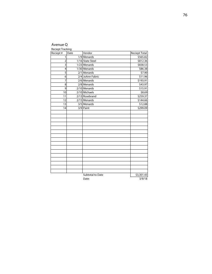
running over. In order to maintain this budget I kept a constant running total through
receipt tracking so that I knew where the budget stood at every turn. Though I was
diligent in the cost analysis process, there were some unanticipated expenses that ate
into the contingency factor I carried on the show. The cost of purchasing duvetyn for
interior masking at $259.37 was one of those unexpected expenses, but thankfully the
budgeted contingency factor covered it. The budget summary for the show revealed
that the production spent $3,301.43 of the total budget, leaving $198.57 to spare.
Page 35
31
Chapter 9: Conclusion
The production of Avenue Q by the Johnny Carson School of Theatre and Film
at the University of Nebraska provided what I would consider to be an excellent
opportunity for a Master of Fine Arts level technical direction thesis production.
Though this served as my fifth production as technical director within the department,
the show offered several challenges and moments of learning throughout the process.
I was able to utilize skills previously developed as well as new techniques in order to
make the show as successful as possible. I am thankful for the trust and support of the
faculty in allowing me to serve in the role of technical director on this scale of
production without concern that the job would not be completed. At the same time,
having an open door to discuss any challenges provided a reassurance that I would be
able to complete the task at hand. I am also thankful for the willingness and open-
minded nature of director Andy Park in allowing the scenic designer to explore unique
ideas in the design process, ultimately creating what I would consider to be a beautiful
set that worked well for the show, as well as kept me on my toes.
As with most, this production proved to provide some learning opportunities,
however, there was much to take pride in from the finished product. I gained valuable
knowledge regarding the technical aspects of projections and that is a component of
live theatre that will not be going away anytime soon. I also gained more experience in
managing larger labor forces and doing so without becoming frustrated nor
overwhelmed. The short amount of time for engineering forced my focus to be
tightened and output speed increased. Engineering and building a set that could
Page 36
32
effectively be transported through an undersized freight elevator or down a flight of
steps and out a door provided many chances for me to catch myself before creating
something that could not fit out of the building.
Overall, I would say that both the production as a whole and my thesis project
were a resounding success. I was able to continue the educational path of the terminal
degree in my field while at the same time strengthening the skill set with which I
entered the program. I feel that the knowledge I have gained over my time spent at
the University of Nebraska will continue to serve me well as I continue on into the
professional working world.
Page 37
33
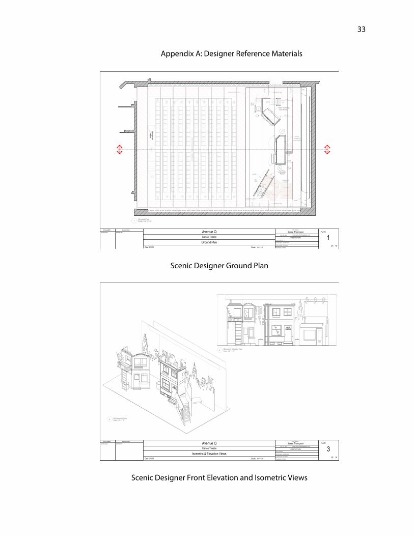
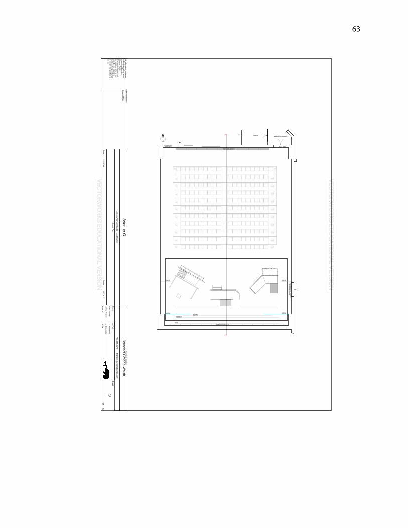
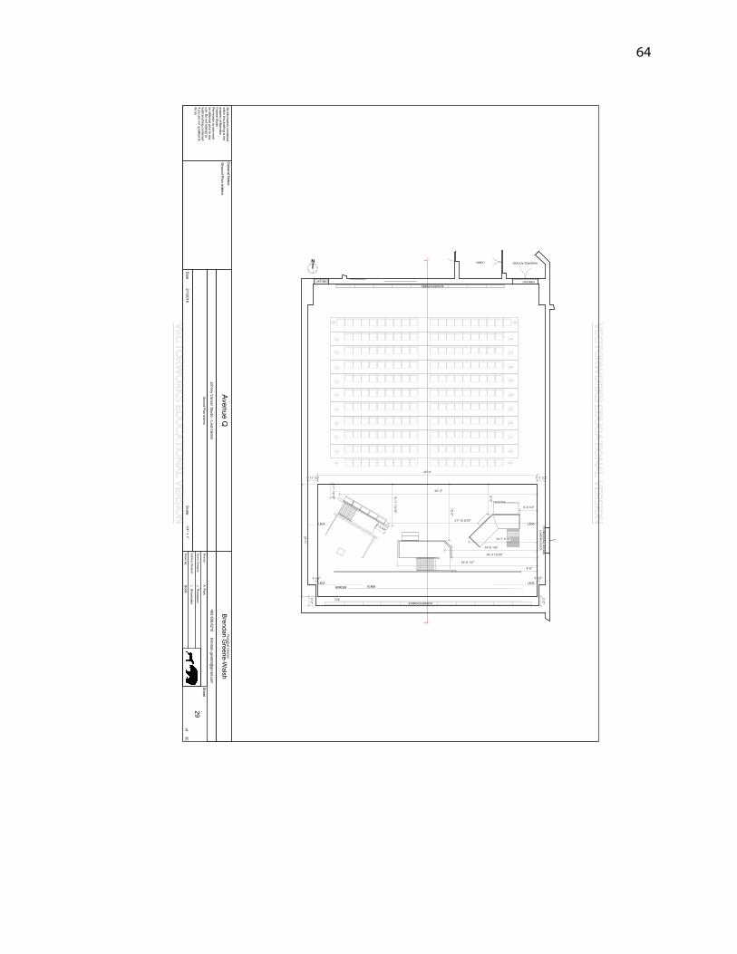
Appendix A: Designer Reference Materials
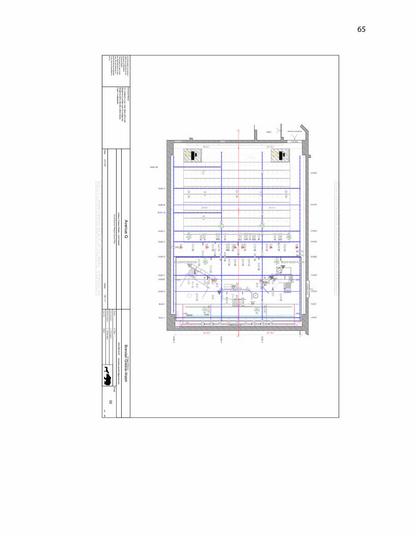
Scenic Designer Ground Plan
Scenic Designer Front Elevation and Isometric Views
Page 38
34
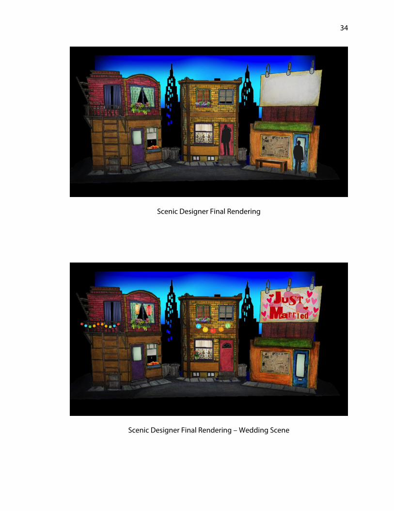
Scenic Designer Final Rendering
Scenic Designer Final Rendering – Wedding Scene
Page 39
35
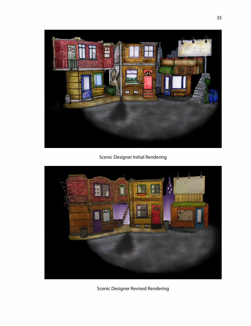
Scenic Designer Initial Rendering
Scenic Designer Revised Rendering
Page 40
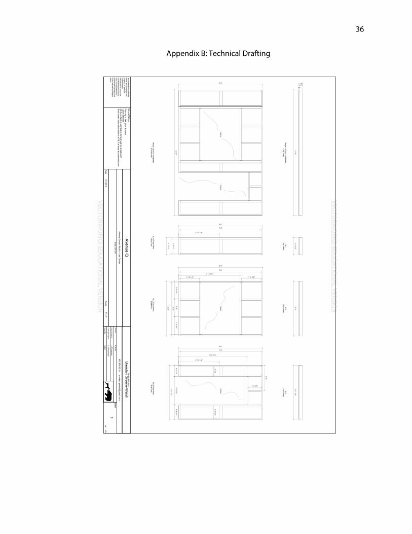
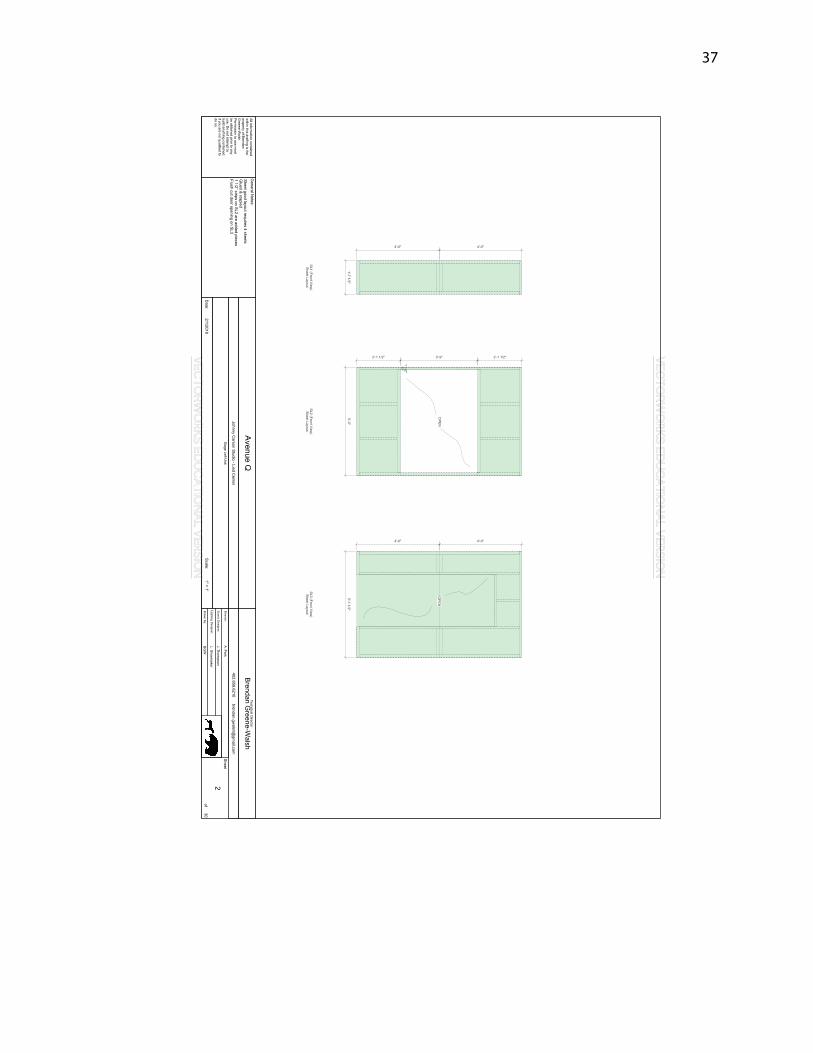
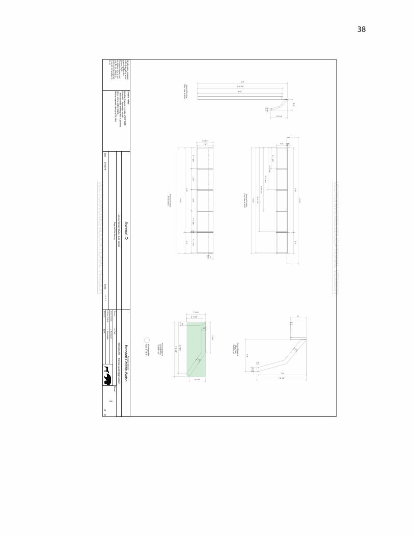
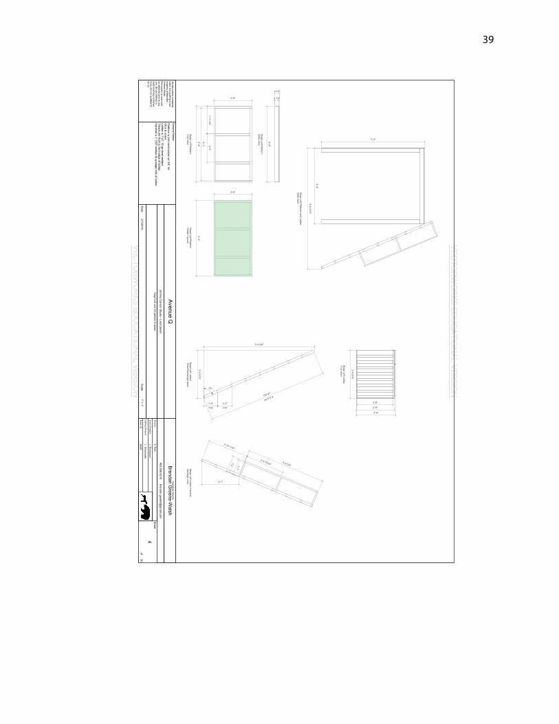
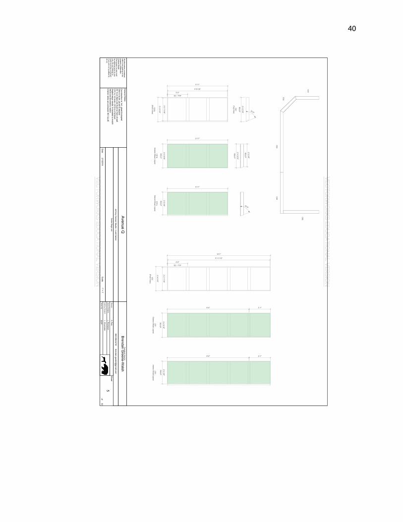
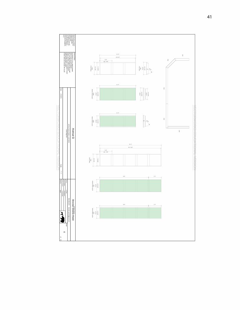
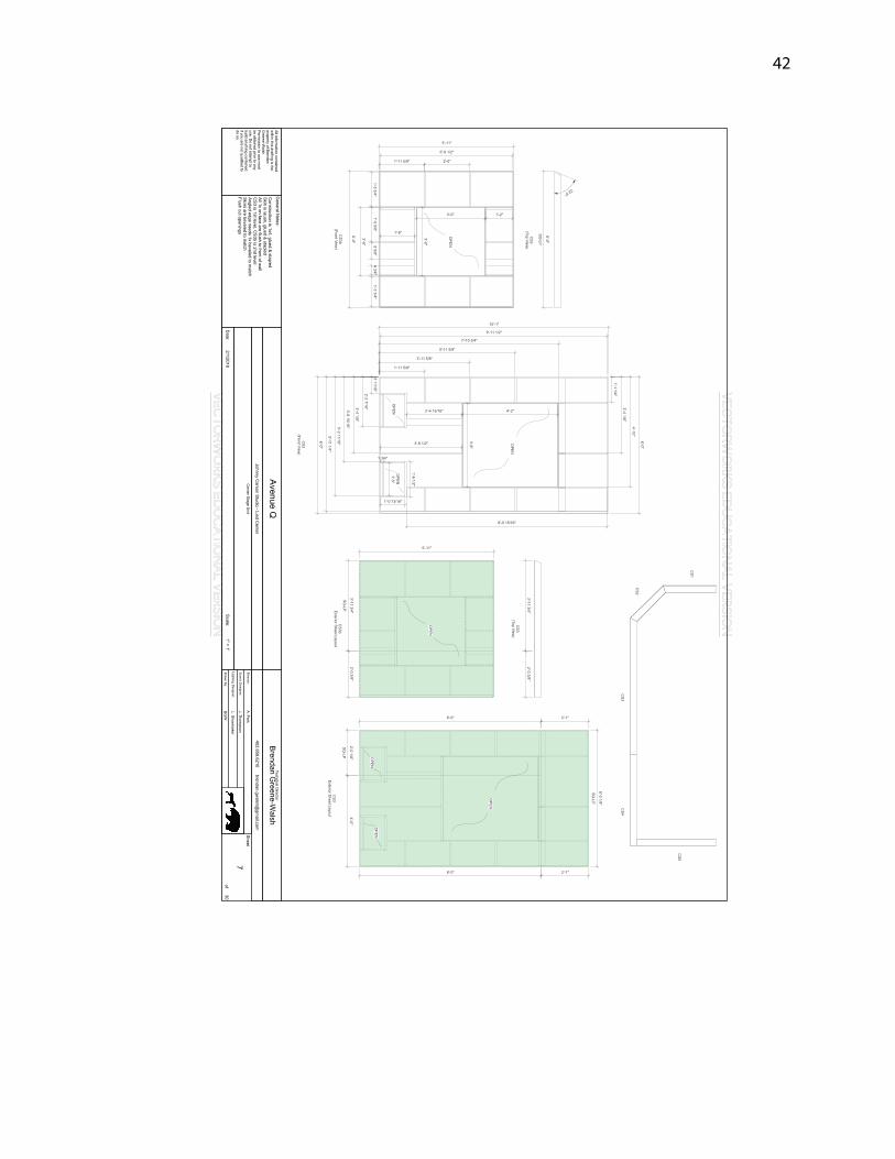
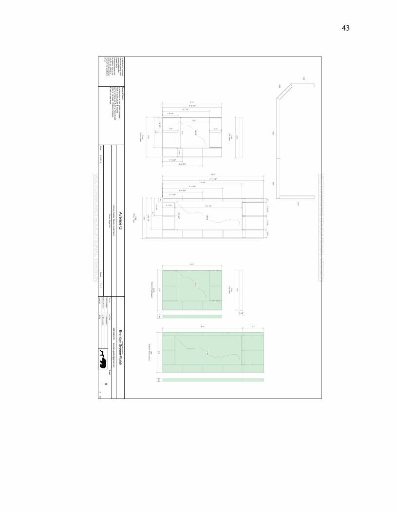
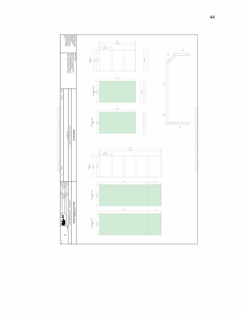
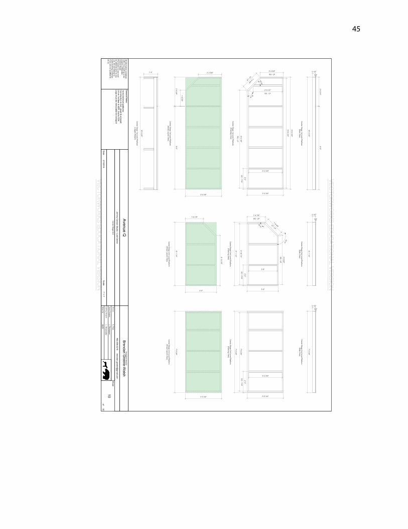
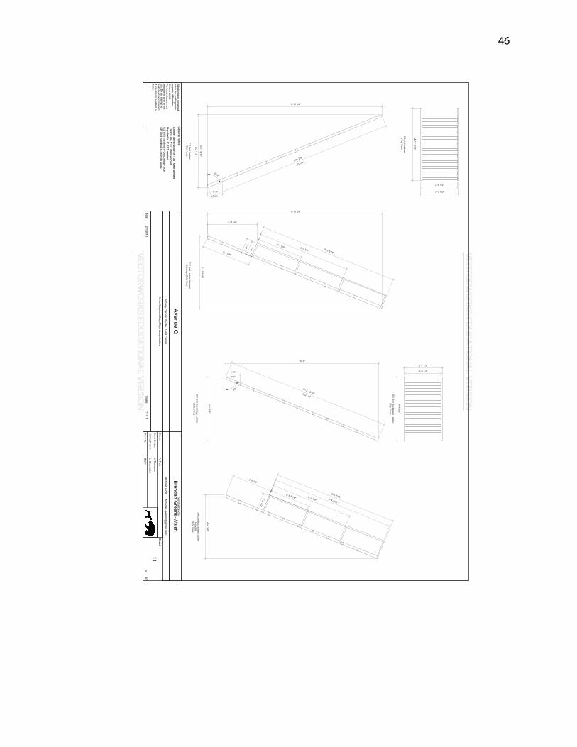
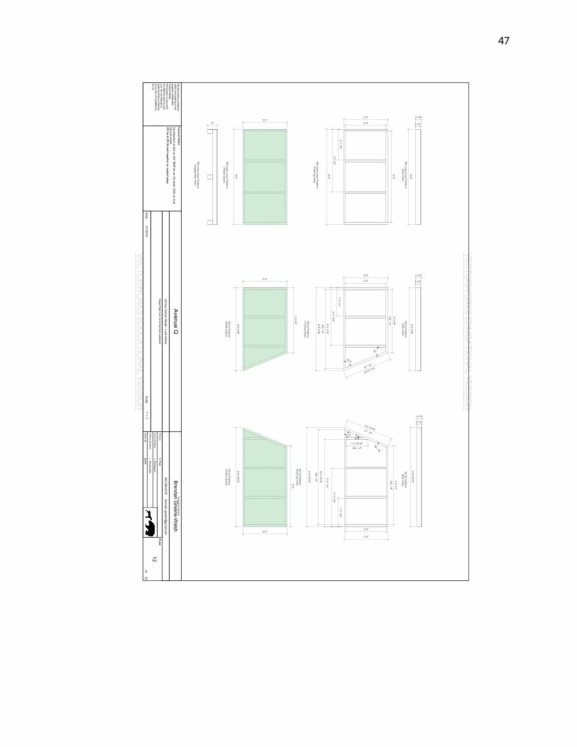
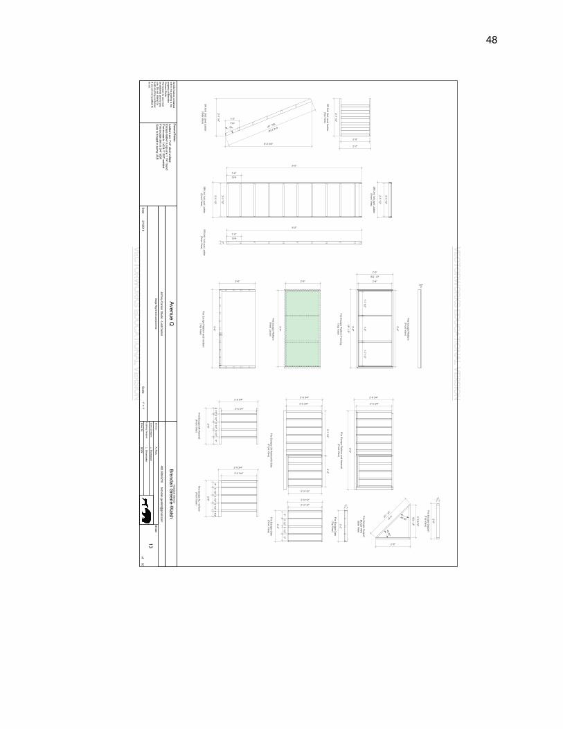
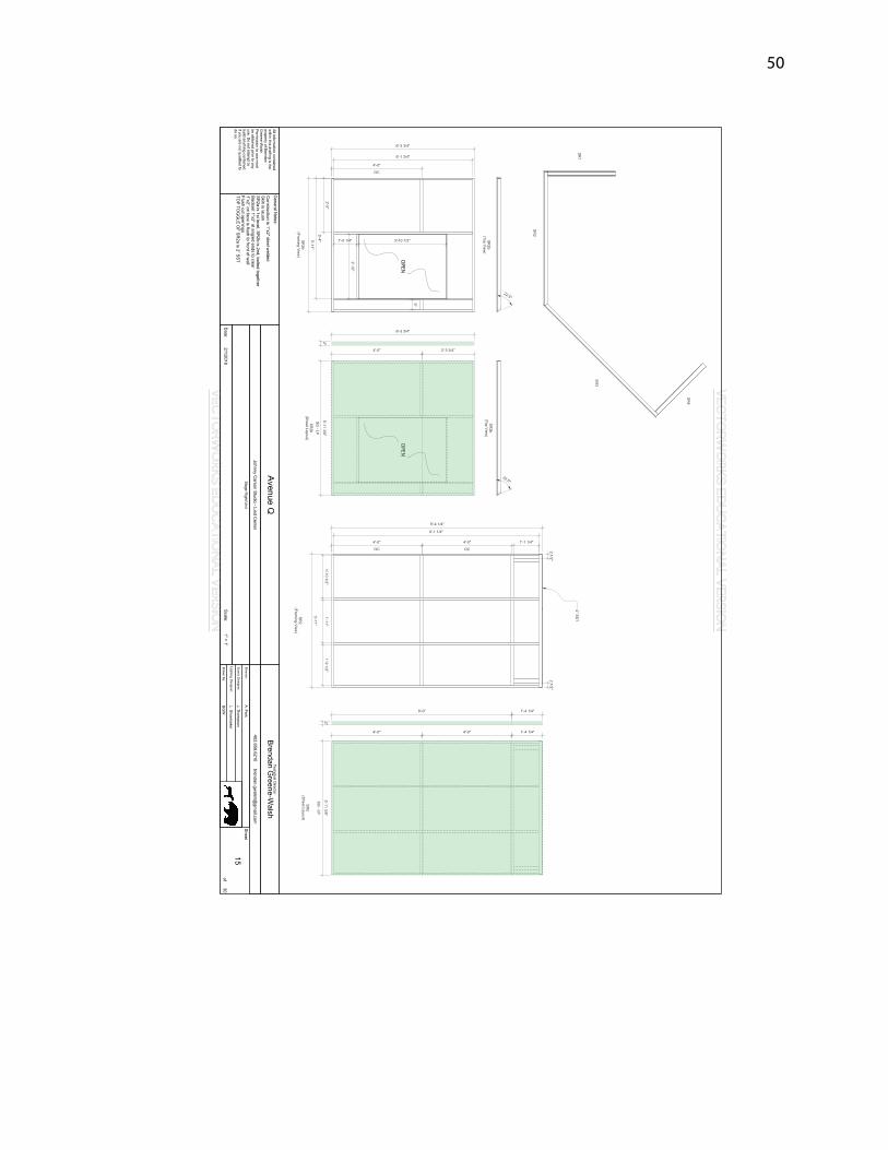
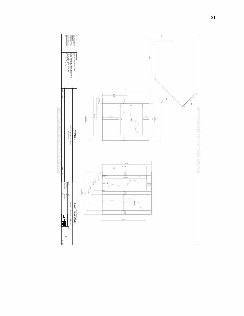
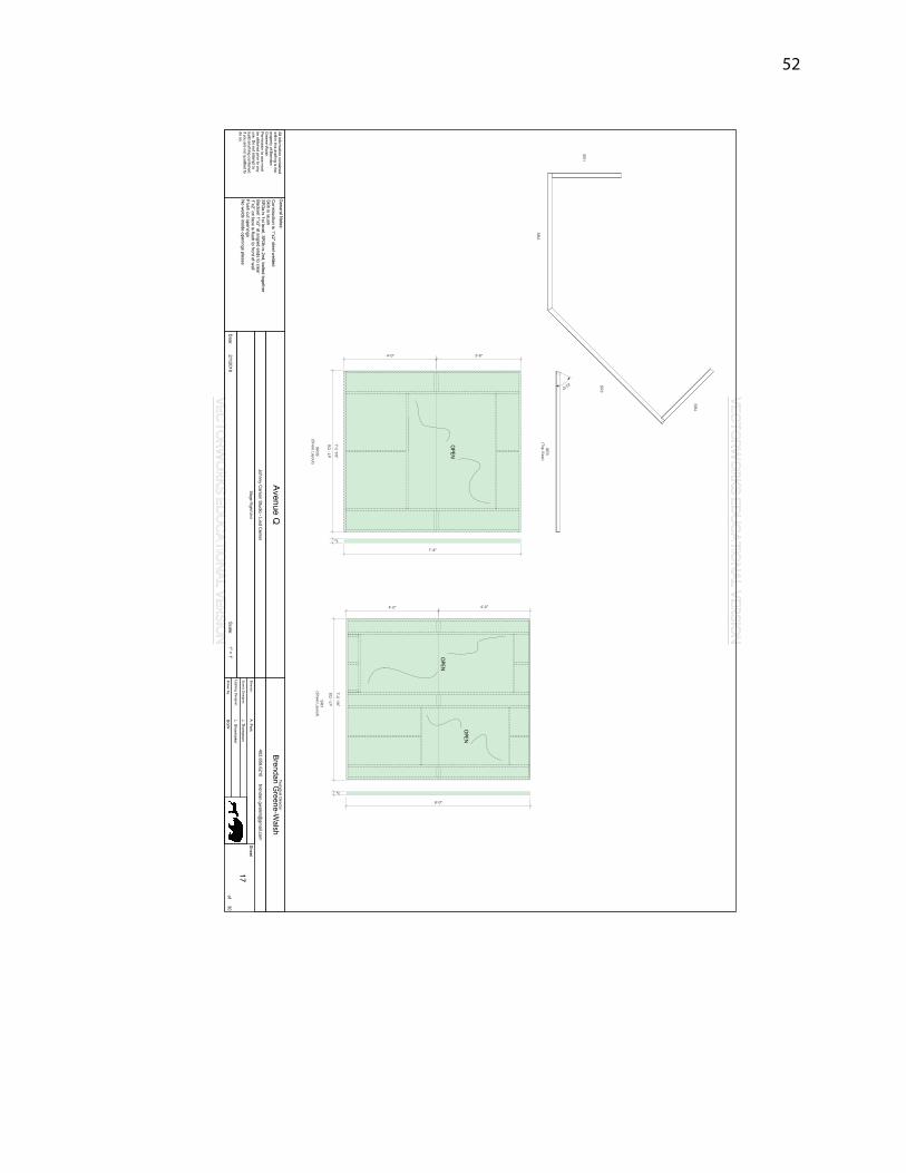
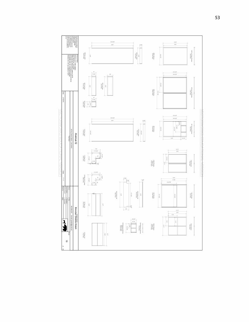
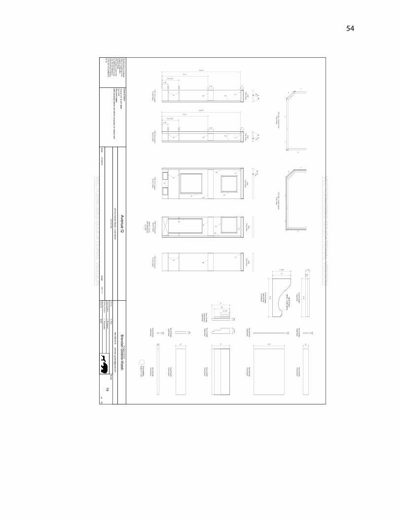
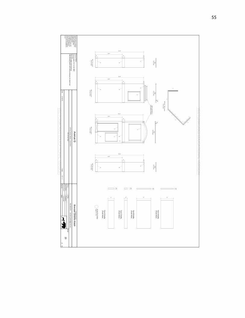
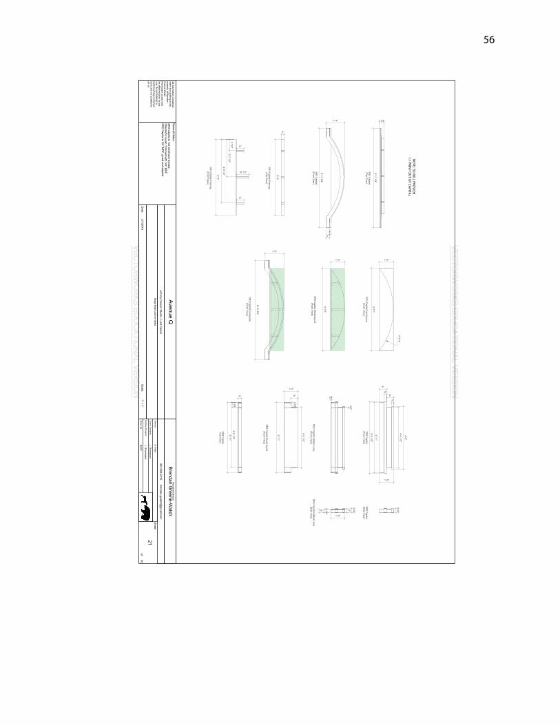
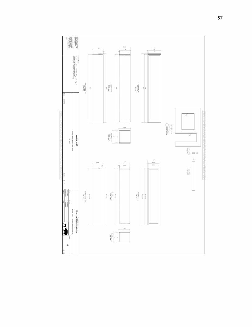
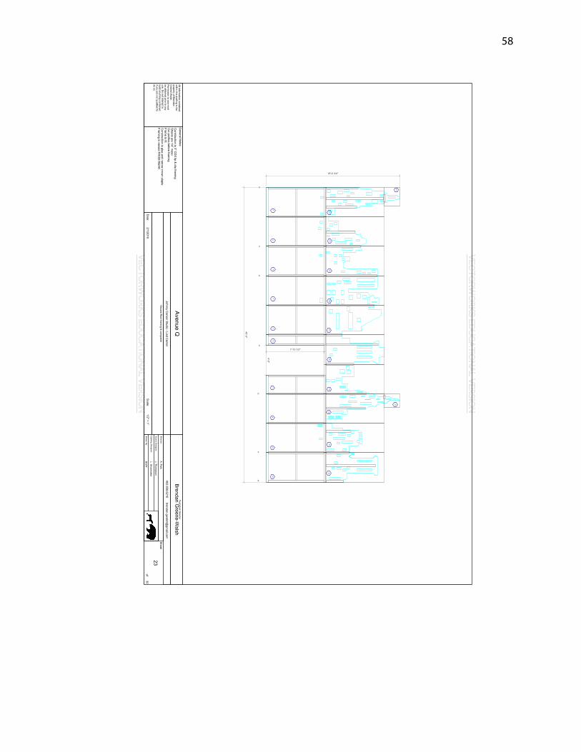
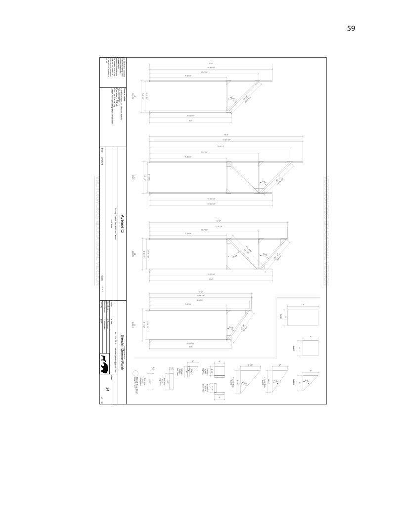
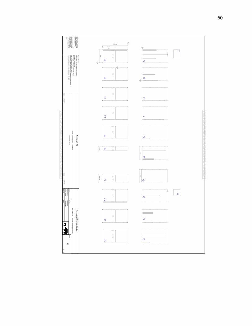
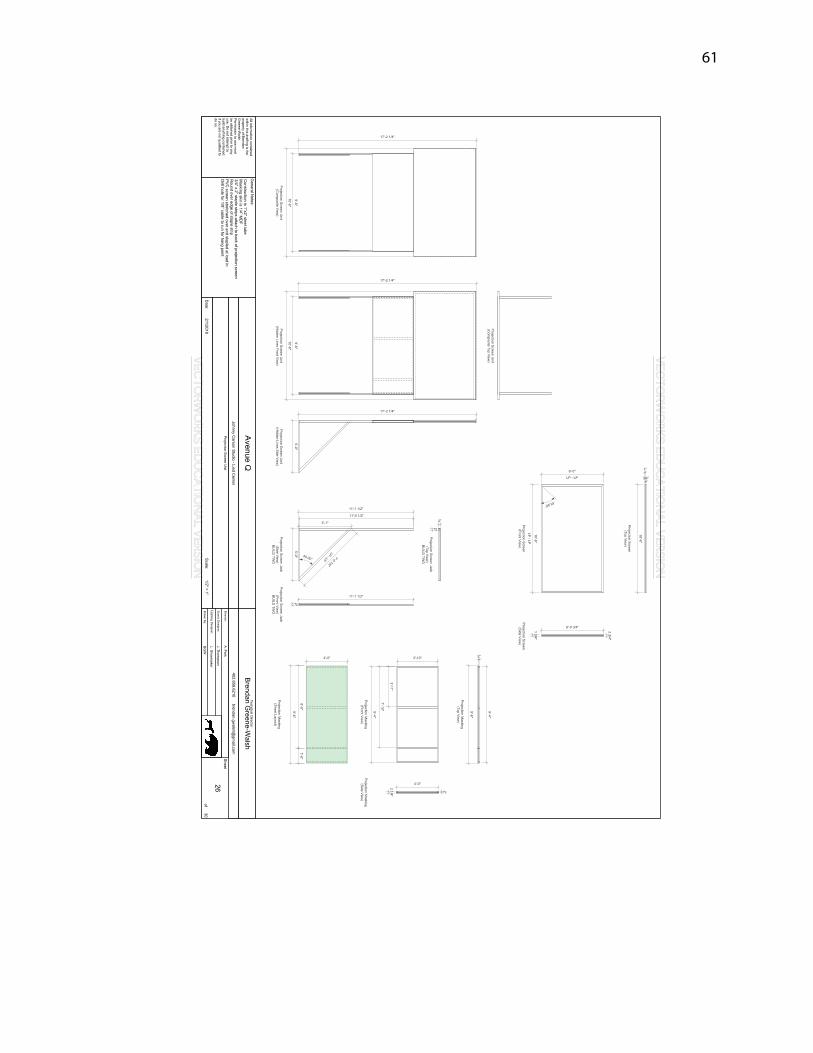
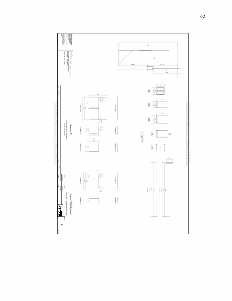
36
Appendix B: Technical Drafting
VECTORW
ORKS EDUCATIO
NAL VERSION
VECTORW
ORKS EDUCATIO
NAL VERSION
Page 41
37
VECTORW
ORKS EDUCATIO
NAL VERSION
VECTORW
ORKS EDUCATIO
NAL VERSION
Page 42
38
Aw
ning detailScale: 3" = 1'-0"
VECTORW
ORKS EDUCATIO
NAL VERSION
VECTORW
ORKS EDUCATIO
NAL VERSION
Page 43
39
VECTORW
ORKS EDUCATIO
NAL VERSION
VECTORW
ORKS EDUCATIO
NAL VERSION
Page 44
40
VECTORW
ORKS EDUCATIO
NAL VERSION
VECTORW
ORKS EDUCATIO
NAL VERSION
Page 45
41
VECTORW
ORKS EDUCATIO
NAL VERSION
VECTORW
ORKS EDUCATIO
NAL VERSION
Page 46
42
VECTORW
ORKS EDUCATIO
NAL VERSION
VECTORW
ORKS EDUCATIO
NAL VERSION
Page 47
43
VECTORW
ORKS EDUCATIO
NAL VERSION
VECTORW
ORKS EDUCATIO
NAL VERSION
Page 48
44
VECTORW
ORKS EDUCATIO
NAL VERSION
VECTORW
ORKS EDUCATIO
NAL VERSION
Page 49
45
VECTORW
ORKS EDUCATIO
NAL VERSION
VECTORW
ORKS EDUCATIO
NAL VERSION
Page 50
46
VECTORW
ORKS EDUCATIO
NAL VERSION
VECTORW
ORKS EDUCATIO
NAL VERSION
Page 51
47
VECTORW
ORKS EDUCATIO
NAL VERSION
VECTORW
ORKS EDUCATIO
NAL VERSION
Page 52
48
VECTORW
ORKS EDUCATIO
NAL VERSION
VECTORW
ORKS EDUCATIO
NAL VERSION
Page 53
49
VECTORW
ORKS EDUCATIO
NAL VERSION
VECTORW
ORKS EDUCATIO
NAL VERSION
Page 54
50
OPEN
OPEN
VECTORW
ORKS EDUCATIO
NAL VERSION
VECTORW
ORKS EDUCATIO
NAL VERSION
Page 55
51
OPEN
OPEN
OPEN
VECTORW
ORKS EDUCATIO
NAL VERSION
VECTORW
ORKS EDUCATIO
NAL VERSION
Page 56
52
OPEN
OPEN
OPEN
VECTORW
ORKS EDUCATIO
NAL VERSION
VECTORW
ORKS EDUCATIO
NAL VERSION
Page 57
53
VECTORW
ORKS EDUCATIO
NAL VERSION
VECTORW
ORKS EDUCATIO
NAL VERSION
Page 58
54
Trim A
Profile(Front View
)
Trim B Profile
(Front View)
Trim C Profile
(Front View)
Trim D
Profile(Front View
)
Trim E Profile
(Front View)
Trim A
Profile(Side View
)
Trim B Profile
(Side View)
Trim C Profile
(Side View)
Trim D
Profile(Side View
)
Trim E Profile
(Side View)
Trim C Profile
Stack layout(Side View
)
Trim Profiles
Scale: 3" = 1'-0"
CS Unit Capital
BUILD
FOU
R(Front View
)
CS Unit Capital
(Top View)
NO
TE: TD W
ILLPRIN
T 1:1 FOR CAPITAL
VECTORW
ORKS EDUCATIO
NAL VERSION
VECTORW
ORKS EDUCATIO
NAL VERSION
Page 59
55
NO
TE: SEE PLATE 21FO
R CAPITAL DETA
ILS
Trim A
Profile(Front View
)
Trim B Profile
(Front View)
Trim C Profile
(Front View)
Trim D
Profile(Front View
)
SR Unit Trim
ProfilesScale: 3" = 1'-0"
VECTORW
ORKS EDUCATIO
NAL VERSION
VECTORW
ORKS EDUCATIO
NAL VERSION
Page 60
56
NO
TE: TD W
ILL PROVID
E1:1 PRIN
T OU
T OF CAPITAL
VECTORW
ORKS EDUCATIO
NAL VERSION
VECTORW
ORKS EDUCATIO
NAL VERSION
Page 61
57
SL Unit Trim
Scale: 1/2" = 1'-0"
VECTORW
ORKS EDUCATIO
NAL VERSION
VECTORW
ORKS EDUCATIO
NAL VERSION
Page 62
58
2221
12
34
56
78
910
1112
1314
1516
1718
1920
J1J2
J2J3
J1J4
J4
VECTORW
ORKS EDUCATIO
NAL VERSION
VECTORW
ORKS EDUCATIO
NAL VERSION
Page 63
59
J1BU
ILD 2
J2BU
ILD 2
J3BU
ILD 1
J4BU
ILD 2
J3 Corner BlockBuild 1
J4 Corner BlockBuild 2
Build 3
Build 7Build 14
Foot braceBuild 7
(Top View)
Foot braceBuild 7
(Front View)
Foot braceBuild 7
(Side View)
Foot strapBuild 7
(Top View)
Foot strapBuild 7
(Front View)
Block & Brace detail
Scale: 3" = 1'-0"
VECTORW
ORKS EDUCATIO
NAL VERSION
VECTORW
ORKS EDUCATIO
NAL VERSION
Page 64
60
12
34
510
98
76
1312
1114
1615
1718
1920
2221
VECTORW
ORKS EDUCATIO
NAL VERSION
VECTORW
ORKS EDUCATIO
NAL VERSION
Page 65
61
VECTORW
ORKS EDUCATIO
NAL VERSION
VECTORW
ORKS EDUCATIO
NAL VERSION
Page 66
62
Cradle(Top View
)Cradle
(Side View)
Cradle(Front View
)
Cradle(Side View
)Cradle
(Top View)
Cradle Stab(Front View
)
Cradle Stab(Side View
)
Projector CradleScale: 1" = 1'-0"
CS Hand Rail (SL)
CS Hand Rail (SL)
CS Hand Rail (SR)
CS Hand Rail (U
S)SR H
and Rail (SL)SR H
and Rail (SR)
CS Hand Rail (SR)
CS Hand Rail (U
S)SR H
and Rail (SL)SR H
and Rail (SR)
VECTORW
ORKS EDUCATIO
NAL VERSION
VECTORW
ORKS EDUCATIO
NAL VERSION
Page 67
63
LEGSSCRIM
BORDER
CYC
LEGS LEGS
LEGS
VECTORW
ORKS EDUCATIO
NAL VERSION
VECTORW
ORKS EDUCATIO
NAL VERSION
Page 68
64
LEGSSCRIMBORDER
CYC
LEGS LEGS
LEGS
VECTORW
ORKS EDUCATIO
NAL VERSION
VECTORW
ORKS EDUCATIO
NAL VERSION
Page 69
65
LEGSSCRIMBORDER
CYC
LEGS LEGS
LEGS
VECTORW
ORKS EDUCATIO
NAL VERSION
VECTORW
ORKS EDUCATIO
NAL VERSION
Page 70
66
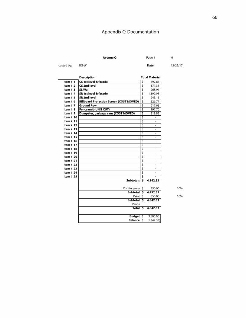
Appendix C: Documentation
Avenue Q Page # 0
costed by: BG-W Date: 12/29/17
Description Total MaterialItem # 1 CS 1st level & façade 897.88$ Item # 2 CS 2nd level 171.38$ Item # 3 SL Wall 268.91$ Item # 4 SR 1st level & façade 1,199.98$ Item # 5 SR 2nd level 243.15$ Item # 6 Billboard Projection Screen (COST MOVED) 326.77$ Item # 7 Ground Row 617.68$ Item # 8 Fence unit (UNIT CUT) 197.76$ Item # 9 Dumpster, garbage cans (COST MOVED) 218.82$ Item # 10 -$ Item # 11 -$ Item # 12 -$ Item # 13 -$ Item # 14 -$ Item # 15 -$ Item # 16 -$ Item # 17 -$ Item # 18 -$ Item # 19 -$ Item # 20 -$ Item # 21 -$ Item # 22 -$ Item # 23 -$ Item # 24 -$ Item # 25 -$
Subtotals 4,142.33$
Contingency 350.00$ 10%Subtotal 4,492.33$
Paint 350.00$ 10%Subtotal 4,842.33$
PropsTotal 4,842.33$
Budget 3,500.00$ Balance (1,342.33)$
Page 71
67
Avenue Q Page # 1
costed by: BG-W Date: 12/29/17
CONSTRUCTION DETAILS
Structure: CS 1st level & façade
Construction Method: Standard 1x4 constructionGlue & staple
Details:
Hardware:
MATERIAL
Item Quantity (ea) Unit Cost Total Cost3/4" 4x8 CDX 2 24.28$ 48.56$ 1/4" 4x8 Maso 13.48$ -$ 1/4" 4x8 Lauan 16 13.98$ 223.68$ 3/4" 4x8 MDF 3 28.99$ 86.97$ 1/2" 4x8 MDF 3 24.68$ 74.04$ 2x4x8 15 2.98$ 44.70$ 1"x2"x24' 16 ga 15 20.00$ 300.00$
1"x24' SST 16 ga 2 17.00$ 34.00$ 34"x80" door 1 58.00$ 58.00$ Door handle 1 12.99$ 12.99$ Hinges 6 2.49$ 14.94$
-$ -$ -$ -$ -$ -$ -$ -$ -$
Totals 897.88$
Page 72
68
Avenue Q Page # 2
costed by: BG-W Date: 12/29/17
CONSTRUCTION DETAILS
Structure: CS 2nd level
Construction Method: Standard 1x4 constructionGlue and staple
Details:
Hardware:
MATERIAL
Item Quantity (ea) Unit Cost Total Cost3/4" 4x8 CDX 2 24.28$ 48.56$ 2x4x8 18 2.98$ 53.64$ 2x4x12 2 4.59$ 9.18$ 1"x2"x24' 16ga 3 20.00$ 60.00$
-$ -$ -$ -$ -$ -$ -$ -$ -$ -$ -$ -$ -$ -$ -$ -$
Totals 171.38$
Page 73
69
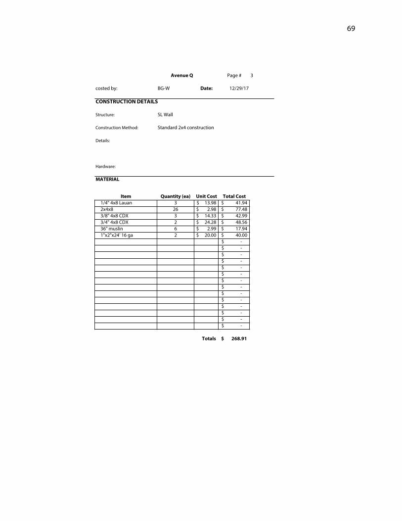
Avenue Q Page # 3
costed by: BG-W Date: 12/29/17
CONSTRUCTION DETAILS
Structure: SL Wall
Construction Method: Standard 2x4 construction
Details:
Hardware:
MATERIAL
Item Quantity (ea) Unit Cost Total Cost1/4" 4x8 Lauan 3 13.98$ 41.94$ 2x4x8 26 2.98$ 77.48$ 3/8" 4x8 CDX 3 14.33$ 42.99$ 3/4" 4x8 CDX 2 24.28$ 48.56$ 36" muslin 6 2.99$ 17.94$ 1"x2"x24' 16 ga 2 20.00$ 40.00$
-$ -$ -$ -$ -$ -$ -$ -$ -$ -$ -$ -$ -$ -$
Totals 268.91$
Page 74
70
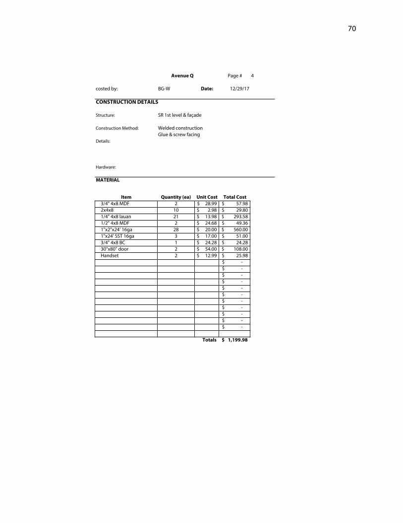
Avenue Q Page # 4
costed by: BG-W Date: 12/29/17
CONSTRUCTION DETAILS
Structure: SR 1st level & façade
Construction Method: Welded constructionGlue & screw facing
Details:
Hardware:
MATERIAL
Item Quantity (ea) Unit Cost Total Cost3/4" 4x8 MDF 2 28.99$ 57.98$ 2x4x8 10 2.98$ 29.80$ 1/4" 4x8 lauan 21 13.98$ 293.58$ 1/2" 4x8 MDF 2 24.68$ 49.36$ 1"x2"x24' 16ga 28 20.00$ 560.00$ 1"x24' SST 16ga 3 17.00$ 51.00$ 3/4" 4x8 BC 1 24.28$ 24.28$ 30"x80" door 2 54.00$ 108.00$ Handset 2 12.99$ 25.98$
-$ -$ -$ -$ -$ -$ -$ -$ -$ -$ -$
Totals 1,199.98$
Page 75
71
Avenue Q Page # 5
costed by: BG-W Date: 12/29/17
CONSTRUCTION DETAILS
Structure: SR 2nd level
Construction Method: Welded constrcutionGlue & screw facing
Details:
Hardware:
MATERIAL
Item Quantity (ea) Unit Cost Total Cost3/4" 4x8 CDX 3 24.28$ 72.84$ 1/2" 4x8 BC 1 22.95$ 22.95$ 2x4x8 12 2.98$ 35.76$ 2x4x10 8 3.95$ 31.60$ 1"x2"x24' 16ga 4 20.00$ 80.00$
-$ -$ -$ -$ -$ -$ -$ -$ -$ -$ -$ -$ -$ -$ -$
Totals 243.15$
Page 76
72
Avenue Q Page # 6
costed by: BG-W Date: 12/29/17
CONSTRUCTION DETAILS
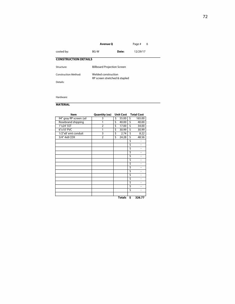
Structure: Billboard Projection Screen
Construction Method: Welded constructionRP screen stretched & stapled
Details:
Hardware:
MATERIAL
Item Quantity (ea) Unit Cost Total Cost94" gray RP screen /yd 3 55.00$ 165.00$ Rosebrand shipping 1 40.00$ 40.00$ 1"x24' SST 2 17.00$ 34.00$ 6"x10' PVC 1 30.99$ 30.99$ 1/2"x8' emt conduit 3 2.74$ 8.22$ 3/4" 4x8 CDX 2 24.28$ 48.56$
-$ -$ -$ -$ -$ -$ -$ -$ -$ -$ -$ -$ -$ -$
Totals 326.77$
Page 77
73
Avenue Q Page # 7
costed by: BG-W Date: 12/29/17
CONSTRUCTION DETAILS
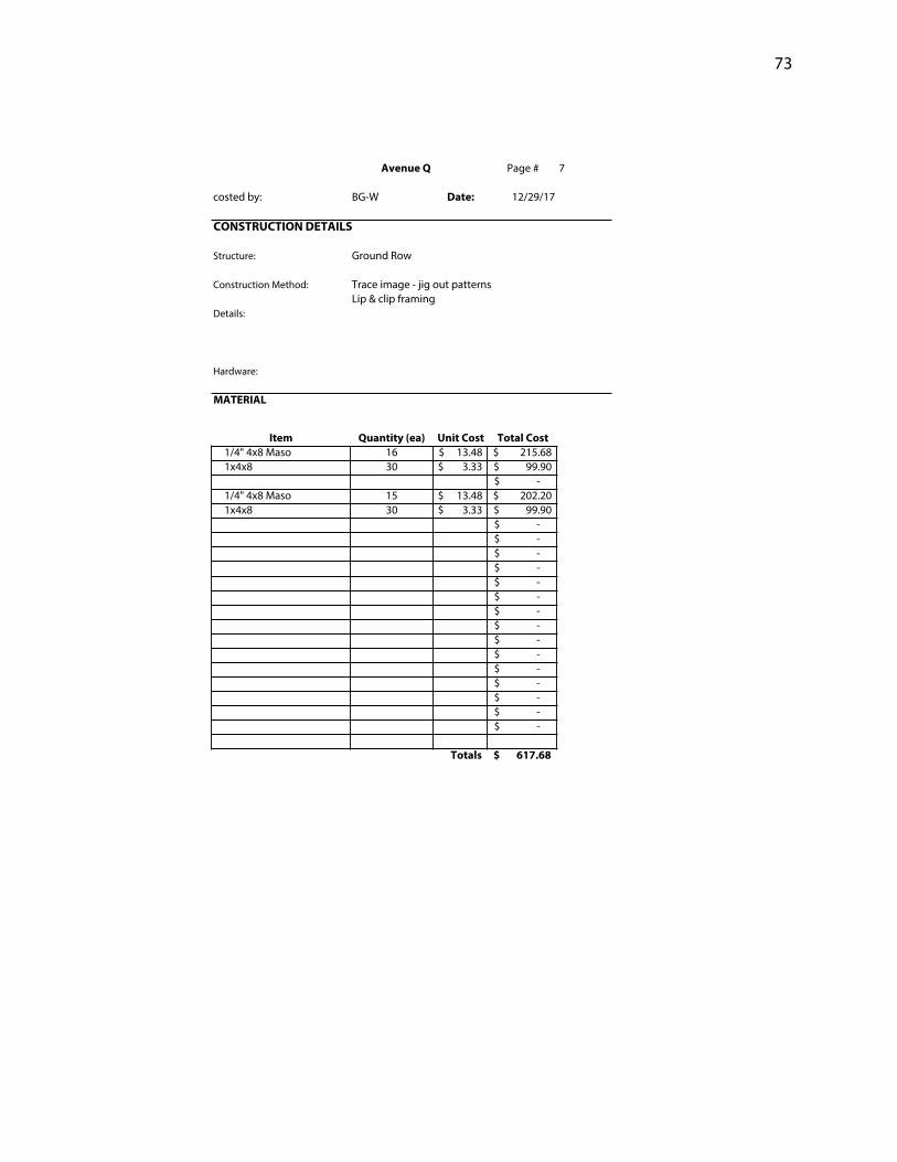
Structure: Ground Row
Construction Method: Trace image - jig out patternsLip & clip framing
Details:
Hardware:
MATERIAL
Item Quantity (ea) Unit Cost Total Cost1/4" 4x8 Maso 16 13.48$ 215.68$ 1x4x8 30 3.33$ 99.90$
-$ 1/4" 4x8 Maso 15 13.48$ 202.20$ 1x4x8 30 3.33$ 99.90$
-$ -$ -$ -$ -$ -$ -$ -$ -$ -$ -$ -$ -$ -$ -$
Totals 617.68$
Page 78
74
Avenue Q Page # 8
costed by: BG-W Date: 12/29/17
CONSTRUCTION DETAILS
Structure: Fence unit
Construction Method:
Details:
Hardware:
MATERIAL
Item Quantity (ea) Unit Cost Total Cost3/4" 4x8 MDF 4 28.99$ 115.96$ 3"x10' PVC 2 8.98$ 17.96$ 2x4x8 8 2.98$ 23.84$ 12" acrylic globe shade 2 20.00$ 40.00$
-$ -$ -$ -$ -$ -$ -$ -$ -$ -$ -$ -$ -$ -$ -$ -$
Totals 197.76$
Page 79
75
Avenue Q Page # 9
costed by: BG-W Date: 12/29/17
CONSTRUCTION DETAILS
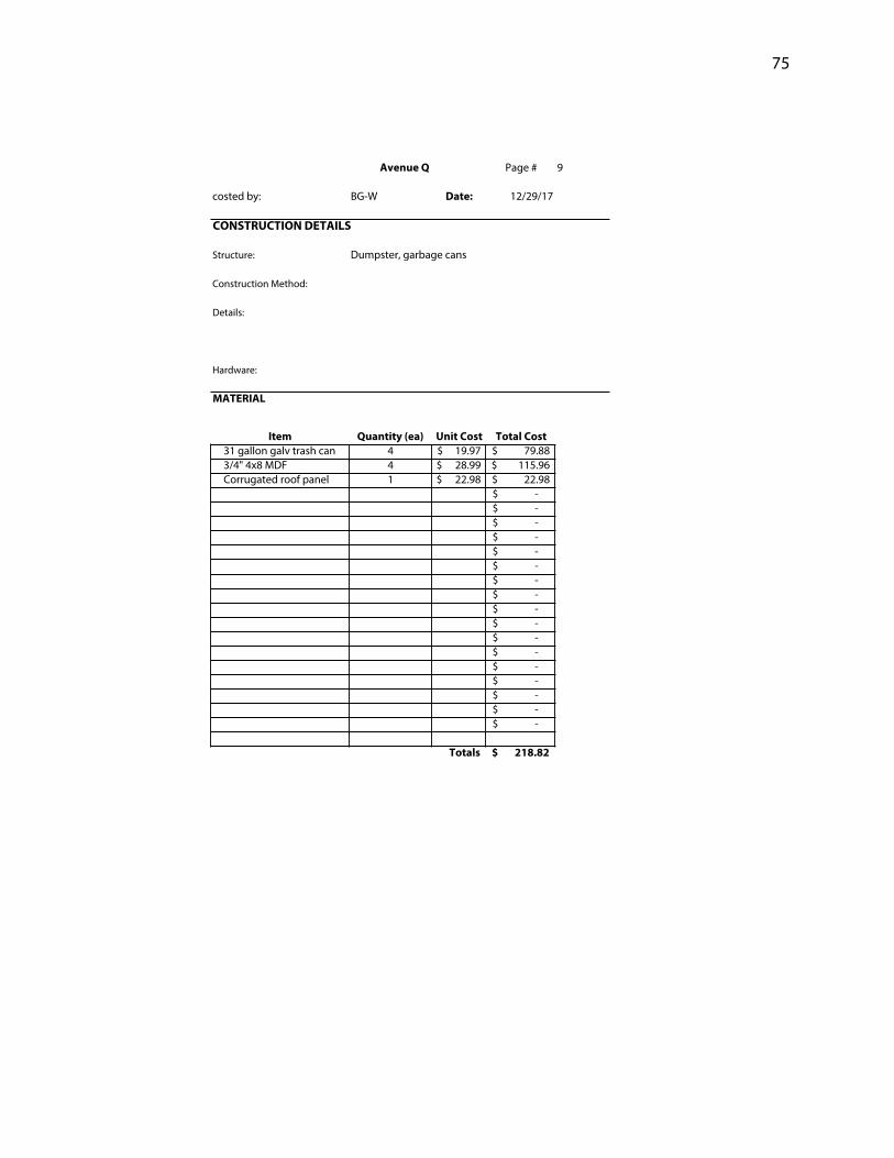
Structure: Dumpster, garbage cans
Construction Method:
Details:
Hardware:
MATERIAL
Item Quantity (ea) Unit Cost Total Cost31 gallon galv trash can 4 19.97$ 79.88$ 3/4" 4x8 MDF 4 28.99$ 115.96$ Corrugated roof panel 1 22.98$ 22.98$
-$ -$ -$ -$ -$ -$ -$ -$ -$ -$ -$ -$ -$ -$ -$ -$ -$
Totals 218.82$
Page 80
76
Avenue QReciept TrackingReciept # Date Vendor Reciept Total
1 1/9 Menards $565.822 1/16 State Steel $812.363 1/23 Menards $838.534 1/30 Menards $86.385 2/1 Menards $7.906 2/4 JoAnn Fabric $11.967 2/6 Menards $193.918 2/8 Menards $43.979 2/10 Menards $15.91
10 2/10 Michaels $8.6911 2/13 Rosebrand $259.3712 2/15 Menards $144.6613 3/5 Menards $12.8814 3/9 Paint $299.09
Subtotal to Date $3,301.43Date: 3/9/18
Page 81
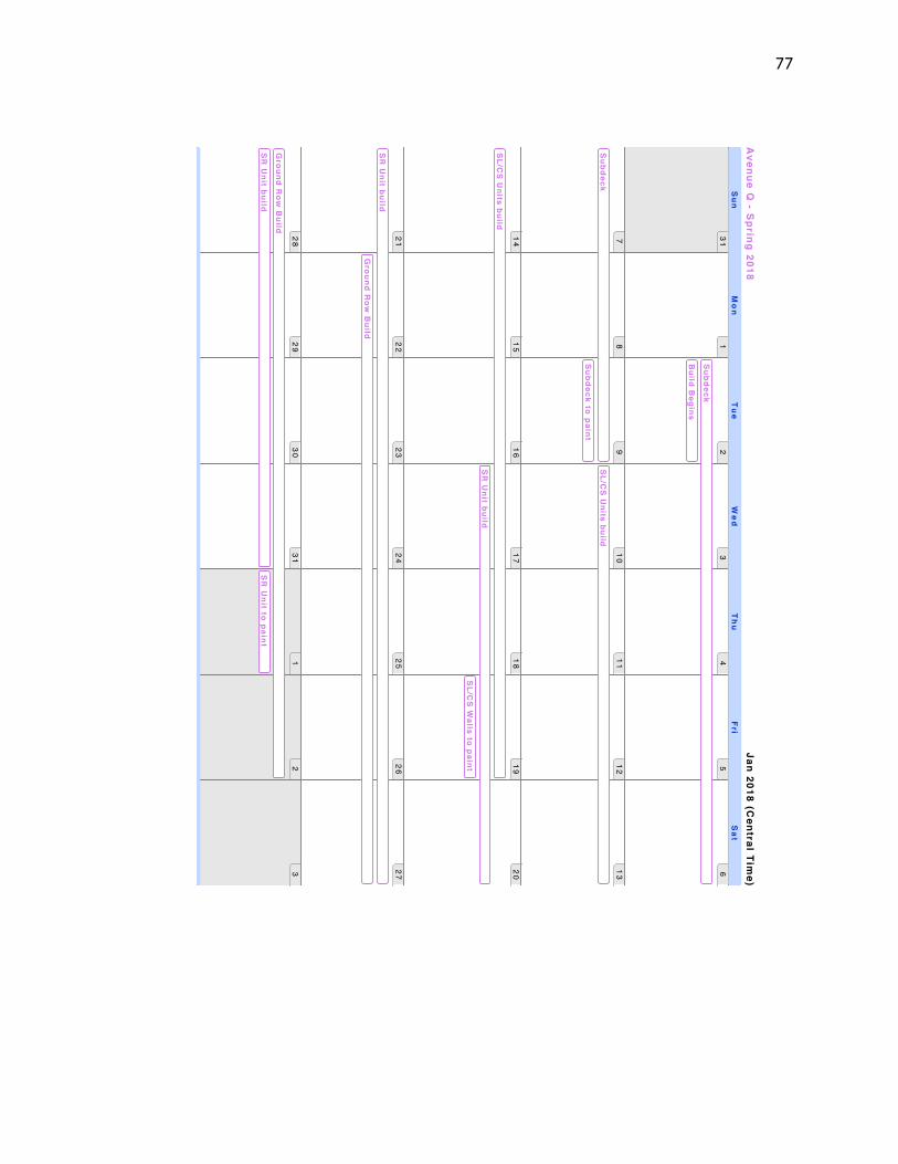
77
Jan 2018 (Central Tim
e)A
venue Q - S
pring 2018
31
12
34
56
78
910
11
12
13
14
15
16
17
18
19
20
21
22
23
24
25
26
27
28
29
30
31
12
3
Subdeck
Build B
egins
Subdeck
Subdeck to paint
SL/C
S U
nits build
SL/C
S U
nits build
SR
Unit build
SL/C
S W
alls to paint
SR
Unit build
Ground R
ow B
uild
Ground R
ow B
uild
SR
Unit build
SR
Unit to paint
Su
nM
on
Tu
eW
ed
Th
uF
riS
at
Page 82
78
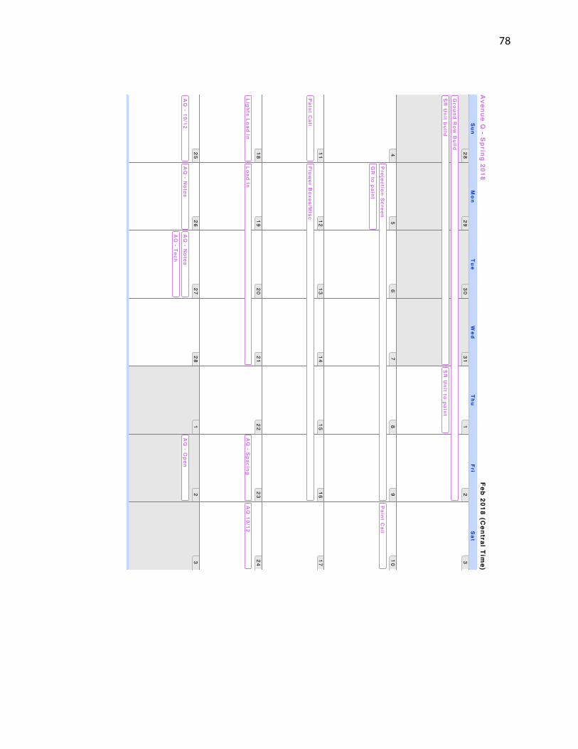
Feb 2018 (Central Tim
e)A
venue Q - S
pring 2018
28
29
30
31
12
3
45
67
89
10
11
12
13
14
15
16
17
18
19
20
21
22
23
24
25
26
27
28
12
3
Ground R
ow B
uild
SR
Unit build
SR
Unit to paint
Projection S
creen
GR
to paint
Paint C
all
Paint C
allFlow
er Boxes/M
isc
Lights Load InLoad In
AQ
- Spacing
Rehearsal
AQ
10/12
AQ
- 10/12A
Q - N
otesA
Q - N
otes
AQ
- Tech
AQ
- Open
Sun
Mo
nT
ue
We
dT
hu
FriS
at
Page 83
79
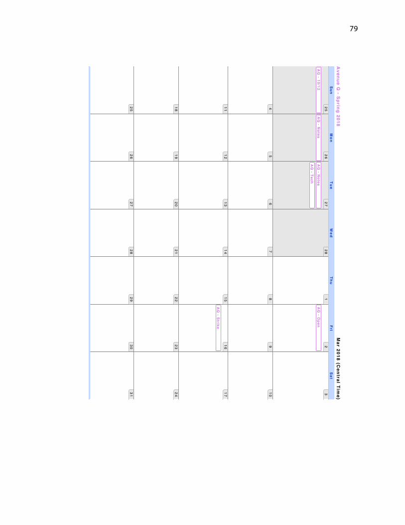
Mar 2018 (C
entral Time)
Avenue Q
- Spring 2018
25
26
27
28
12
3
45
67
89
10
11
12
13
14
15
16
17
18
19
20
21
22
23
24
25
26
27
28
29
30
31
AQ
- 10/12A
Q - N
otesA
Q - N
otes
AQ
- Tech
AQ
- Open
AQ
- Strike
Sun
Mo
nT
ue
We
dT
hu
FriS
at
Page 84
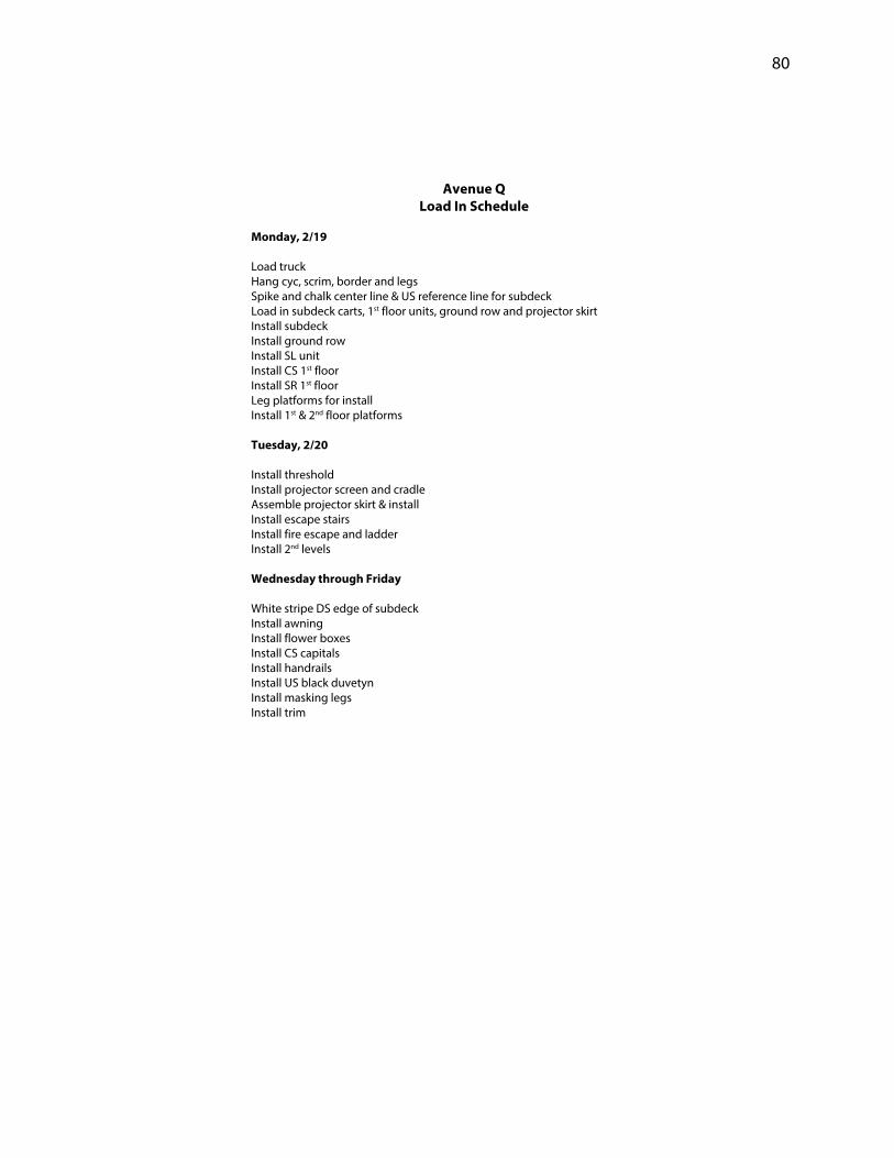
80
Avenue Q Load In Schedule
Monday, 2/19 Load truck Hang cyc, scrim, border and legs Spike and chalk center line & US reference line for subdeck Load in subdeck carts, 1st floor units, ground row and projector skirt Install subdeck Install ground row Install SL unit Install CS 1st floor Install SR 1st floor Leg platforms for install Install 1st & 2nd floor platforms Tuesday, 2/20 Install threshold Install projector screen and cradle Assemble projector skirt & install Install escape stairs Install fire escape and ladder Install 2nd levels Wednesday through Friday White stripe DS edge of subdeck Install awning Install flower boxes Install CS capitals Install handrails Install US black duvetyn Install masking legs Install trim
Page 85
81
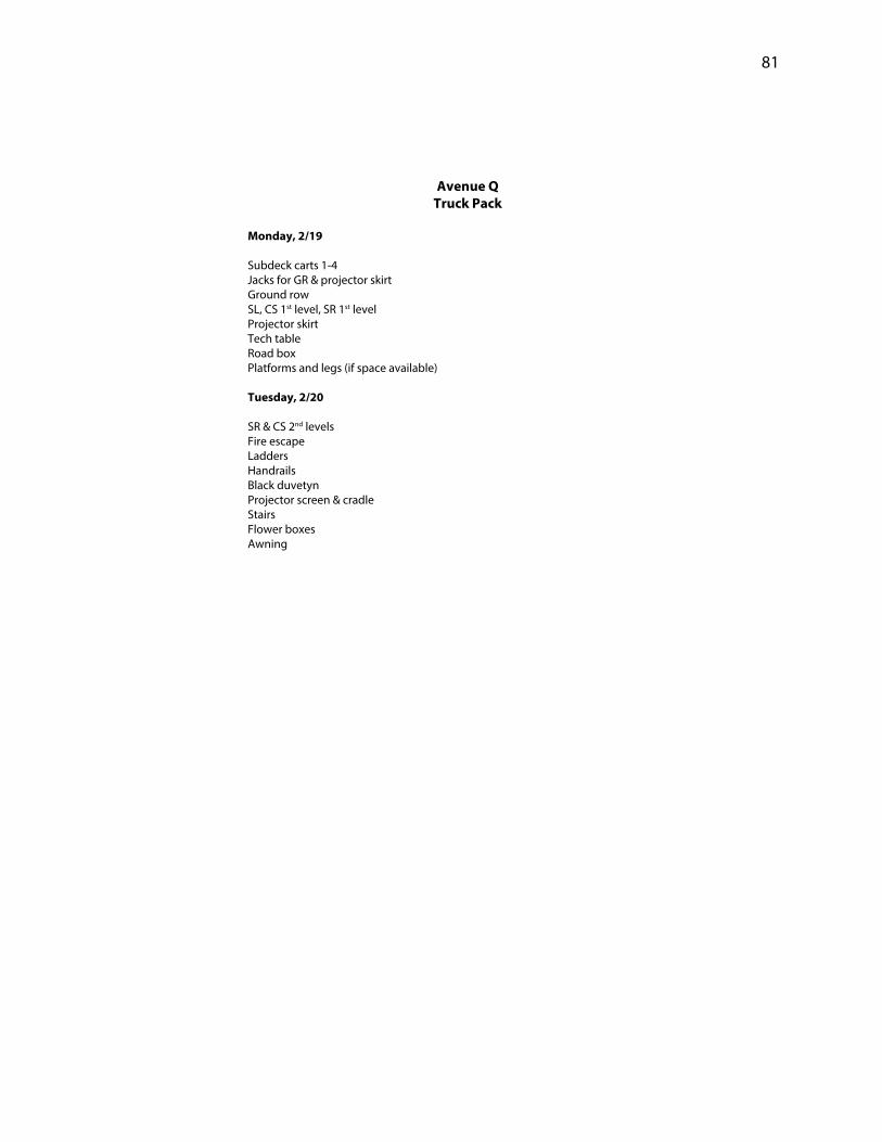
Avenue Q Truck Pack
Monday, 2/19 Subdeck carts 1-4 Jacks for GR & projector skirt Ground row SL, CS 1st level, SR 1st level Projector skirt Tech table Road box Platforms and legs (if space available) Tuesday, 2/20 SR & CS 2nd levels Fire escape Ladders Handrails Black duvetyn Projector screen & cradle Stairs Flower boxes Awning
Page 86
82
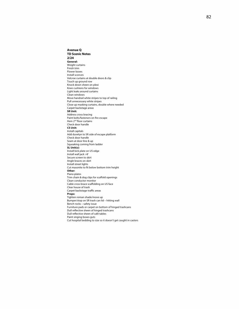
Avenue Q TD Scenic Notes 2/24 General: Weight curtains Finish trim Flower boxes Install sconces Velcroe curtains at double doors & clip Touch up ground row Knock down sheen on plexi Knee cushions for windows Light leaks around curtains Clean windows Move handrail white stripes to top of railing Pull unnecessary white stripes Close up masking curtains, double where needed Carpet backstage areas SR Unit: Address cross bracing Paint bolts/fasteners on fire escape Hem 2nd floor curtains Check door handle CS Unit: Install capitals Add duvetyn to SR side of escape platform Check door handle Seam at door line & up Squeaking coming from ladder SL Unit(s): Install kick plate on US edge Install wall jack >8’ Secure screen to skirt Angle braces on skirt Install street lights Cut masonite to fit below bottom trim height Other: Piano plates Trim chain & dog clips for scaffold openings Clean conductor monitor Cable cross brace scaffolding on US face Clear house of trash Carpet backstage traffic areas Props: Tighten roman shade/move up Bumper/stop on SR trash can lid – hitting wall Bench rocks – safety issue Furniture pads or carpet on bottom of hinged trashcans Dull reflective sheen of hinged trashcans Dull reflective sheen of café tables Paint singing boxes guts Cut hospital bedding to size so it doesn’t get caught in casters
Page 87
83
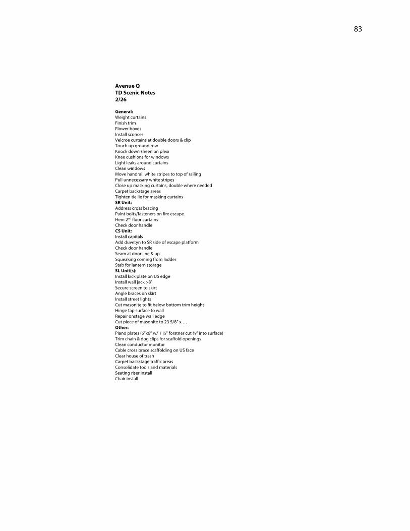
Avenue Q TD Scenic Notes 2/26 General: Weight curtains Finish trim Flower boxes Install sconces Velcroe curtains at double doors & clip Touch up ground row Knock down sheen on plexi Knee cushions for windows Light leaks around curtains Clean windows Move handrail white stripes to top of railing Pull unnecessary white stripes Close up masking curtains, double where needed Carpet backstage areas Tighten tie lie for masking curtains SR Unit: Address cross bracing Paint bolts/fasteners on fire escape Hem 2nd floor curtains Check door handle CS Unit: Install capitals Add duvetyn to SR side of escape platform Check door handle Seam at door line & up Squeaking coming from ladder Stab for lantern storage SL Unit(s): Install kick plate on US edge Install wall jack >8’ Secure screen to skirt Angle braces on skirt Install street lights Cut masonite to fit below bottom trim height Hinge tap surface to wall Repair onstage wall edge Cut piece of masonite to 23 5/8” x … Other: Piano plates (6”x6” w/ 1 ½” forstner cut ¼” into surface) Trim chain & dog clips for scaffold openings Clean conductor monitor Cable cross brace scaffolding on US face Clear house of trash Carpet backstage traffic areas Consolidate tools and materials Seating riser install Chair install
Page 88
84
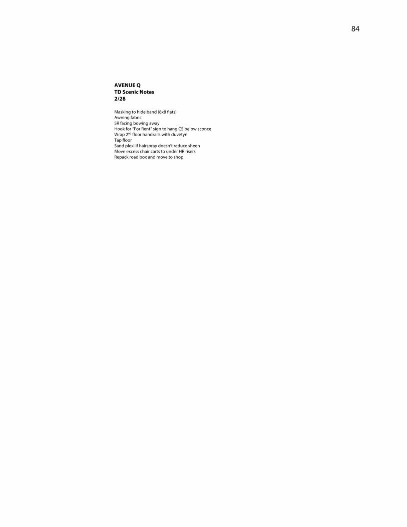
AVENUE Q TD Scenic Notes 2/28 Masking to hide band (8x8 flats) Awning fabric SR facing bowing away Hook for “For Rent” sign to hang CS below sconce Wrap 2nd floor handrails with duvetyn Tap floor Sand plexi if hairspray doesn’t reduce sheen Move excess chair carts to under HR risers Repack road box and move to shop
Page 89
85
Avenue Q Strike (3/16)
Seating Units: (Jeff w/Michael, Colin, Karen, RaeAnn & students) Handrails, riser skirts, seats to carts, center aisle platforms & stairs Collapse units once clear SR DS Masking curtain (BGW) Projector, video gear (BGW & Dylan) SR UNIT: (Dan, Nate, BGW & Dylan) Duvetyn masking 2nd level façade Fire escape & ladders 2nd level platform 1st level façade & platform KEEP: Steel, door w/jamb duvetyn, legs & jacks CS UNIT: (Michael, Colin, Karen & RaeAnn) Duvetyn 2nd level façade Ladder 2nd level platform 1st level platform & façade KEEP: Door w/jamb, ladder, duvetyn SL UNIT: (Dan, Nate, BGW & Dylan) Masking walls Platform Ladder Façade Projector masking Projector screen Projector cradle KEEP: Door, ladder, jacks, masking, screen, steel & cradle GROUND ROW: (BGW, Michael, Colin, Karen) Begin on SL side KEEP: 2 jacks SOFT GOODS: (All) Pull bottom pipe from cyc Basket cyc & scrim as grid lowers Fold in Lied Mainstage? Legs & cyc to hamper, Z Tech to Jeff Scrim to Temple SUBDECK: (Dan, Nate, Dylan, RaeAnn) Begin DSL work to DSR, MSL work to MSR, USL work to USR GRID: (All) Remove conductor TV (Nate, BGW) Pull pipes and reset All JCSTF cheeseboroughs to Brendan/buckets (27 total)
Page 90
86
Appendix D: Construction Process Photographs
Center Stage unit framing
Stock door selections
Page 91
87
Ground row trace and cut out process
Stage left unit
Page 92
88
Center stage unit – First floor
Center stage unit – First floor
Page 93
89
Stage right unit – First floor
Stage right unit – First floor
Page 94
90
Stage right unit backside – First floor
Stage right unit – Second level
Page 95
91
Stage right unit – Second level
Stage right unit – Fire escape
Page 96
92
Center stage unit – Second level
Center stage unit – First level
Page 97
93
Stage right unit – Second level
Stage right unit – First level
Page 98
94
Stage right unit – Second level
Center stage unit – First level
Page 99
95
Center stage unit – Second level
Custom built projection screen
Page 100
96
Stage left and center stage units – Disassembled for transport
Stage right unit – Disassembled for transport
Page 101
97
Load-in day one – Sub-deck and drapes installed
Load-in day one – End of day
Page 102
98
Load-in day two – Second level install
Load-in day two – Projection screen and masking
Page 103
99
Load-in day two – End of day
Load-in day two – End of day
Page 104
100
Load-in day three – End of day
Load-in day three – End of day
Page 105
101
Going into tech rehearsals
Page 106
102
Appendix E: Production Photographs
Finished set
Finished set
Page 107
103
Finished set – Stage right unit
Page 108
104
Finished set – Center stage unit
Page 109
105
Finished set – Stage left unit with projection screen
Page 110
106
Production photograph – Avenue Q
Production photograph – Avenue Q
Page 111
107
Production photograph – Avenue Q
Production photography – Avenue Q
Page 112
108
Production photograph – Avenue Q
Production photograph – Avenue Q
Page 113
109
Production photograph – Avenue Q
Production photograph – Avenue Q
Page 114
110
Production photograph – Avenue Q
Production photograph – Avenue Q