Bending diamonds by femtosecond laser ablation P. Balling a , J. Esberg a , K. Kirsebom a , D.Q.S. Le a , U.I. Uggerhøj a, * , S.H. Connell b , J. Härtwig c , F. Masiello c , A. Rommeveaux c a Department of Physics and Astronomy, University of Aarhus, Denmark b Johannesburg University, Johannesburg, South Africa c ESRF, Grenoble, France article info Article history: Received 5 May 2009 Received in revised form 15 June 2009 Available online 23 June 2009 PACS: 61.85.+p 25.75.q 41.74.Ak 41.85.Ja Keywords: Lasers Ablation Crystals Diamonds Channeling abstract We present a new method based on femtosecond laser ablation for the fabrication of statically bent dia- mond crystals. Using this method, curvature radii of 1 m can easily be achieved, and the curvature obtained is very uniform. Since diamond is extremely tolerant to high radiation doses, partly due to its densely packed lattice, such bent crystals are optimal solutions for crystal-based collimation and/or extraction. Furthermore, using interlaced ablation on both sides, the technique opens for the possibility of constructing a crystalline undulator based on the best material known, to approach the enormous beam densities required for lasing operation of such a device. Ó 2009 Elsevier B.V. All rights reserved. 1. Introduction Since its prediction [1] and the first experiments in the late 1970s, the use of and knowledge about particle channeling in bent crystals has increased steadily and is now at a well-established stage where almost all aspects of the phenomenon have been cov- ered. However, for a possible application of the phenomenon as an extraction [2] or collimation [3] device at the LHC at CERN, it is mandatory that the crystal from which the device is made, is able to tolerate extreme radiation doses, being exposed to the tough environment near the main beam. Diamond is such a material, but has hitherto proven almost impossible to bend, being rigid and brittle. We present in the following a method to bend dia- monds to the desired shape, relevant for implementation as an extraction and/or collimation device. In this connection, the unusu- ally high thermal conductivity of diamond combined with its high melting temperature, yields yet another advantage compared to, e.g. silicon, see [4] for a discussion of some of the benefits of diamonds. Measurements were performed in the mid-1990s showing that the deflection efficiency in silicon deteriorated by 6 ± 2%/10 20 p + / cm 2 [5] and diamond is expected to be much more radiation hard, having a much denser lattice than silicon (a ratio of lattice con- stants of only 0.66). Electron densities of the order 10 21 cm 3 have been available at the Final Focus Test Beam (FFTB) at SLAC and the- oretical schemes to increase this by a factor 30 have been devised [6]. It is known from experimental tests at SLAC that a diamond crystal bears no visible influence from being irradiated by the FFTB, whereas aluminum simply evaporates [7]. At the LHC, the crystal being positioned in the beam halo some 6–7 r away from the beam center, the intensity is expected to be about 10 9 p + /s. Nevertheless, occasionally the crystal will intercept much higher intensities and must be able to withstand high doses. 2. Channeling in bent crystals In the so-called continuum approximation [8], charged particles incident on a single-crystal with small angles to crystallographic directions, experience the collective fields as if smeared along the string or plane. If, further, a particle has sufficiently low transverse momentum with respect to the axis or plane of the crystal it can be 0168-583X/$ - see front matter Ó 2009 Elsevier B.V. All rights reserved. doi:10.1016/j.nimb.2009.06.109 * Corresponding author. Tel.: +45 89423738; fax: +45 86120740. E-mail address: [email protected](U.I. Uggerhøj). Nuclear Instruments and Methods in Physics Research B 267 (2009) 2952–2957 Contents lists available at ScienceDirect Nuclear Instruments and Methods in Physics Research B journal homepage: www.elsevier.com/locate/nimb
Transcript
Nuclear Instruments and Methods in Physics Research B 267 (2009) 2952–2957
Contents lists available at ScienceDirect
Nuclear Instruments and Methods in Physics Research B
journal homepage: www.elsevier .com/locate /n imb
Bending diamonds by femtosecond laser ablation
P. Balling a, J. Esberg a, K. Kirsebom a, D.Q.S. Le a, U.I. Uggerhøj a,*, S.H. Connell b,J. Härtwig c, F. Masiello c, A. Rommeveaux c
a Department of Physics and Astronomy, University of Aarhus, Denmarkb Johannesburg University, Johannesburg, South Africac ESRF, Grenoble, France
a r t i c l e i n f o a b s t r a c t
Article history:Received 5 May 2009Received in revised form 15 June 2009Available online 23 June 2009
PACS:61.85.+p25.75.�q41.74.Ak41.85.Ja
Keywords:LasersAblationCrystalsDiamondsChanneling
0168-583X/$ - see front matter � 2009 Elsevier B.V.doi:10.1016/j.nimb.2009.06.109
We present a new method based on femtosecond laser ablation for the fabrication of statically bent dia-mond crystals. Using this method, curvature radii of 1 m can easily be achieved, and the curvatureobtained is very uniform. Since diamond is extremely tolerant to high radiation doses, partly due to itsdensely packed lattice, such bent crystals are optimal solutions for crystal-based collimation and/orextraction. Furthermore, using interlaced ablation on both sides, the technique opens for the possibilityof constructing a crystalline undulator based on the best material known, to approach the enormousbeam densities required for lasing operation of such a device.
� 2009 Elsevier B.V. All rights reserved.
1. Introduction
Since its prediction [1] and the first experiments in the late1970s, the use of and knowledge about particle channeling in bentcrystals has increased steadily and is now at a well-establishedstage where almost all aspects of the phenomenon have been cov-ered. However, for a possible application of the phenomenon as anextraction [2] or collimation [3] device at the LHC at CERN, it ismandatory that the crystal from which the device is made, is ableto tolerate extreme radiation doses, being exposed to the toughenvironment near the main beam. Diamond is such a material,but has hitherto proven almost impossible to bend, being rigidand brittle. We present in the following a method to bend dia-monds to the desired shape, relevant for implementation as anextraction and/or collimation device. In this connection, the unusu-ally high thermal conductivity of diamond combined with its highmelting temperature, yields yet another advantage compared to,e.g. silicon, see [4] for a discussion of some of the benefits ofdiamonds.
All rights reserved.
45 86120740.
Measurements were performed in the mid-1990s showing thatthe deflection efficiency in silicon deteriorated by 6 ± 2%/1020 p+/cm2 [5] and diamond is expected to be much more radiation hard,having a much denser lattice than silicon (a ratio of lattice con-stants of only 0.66). Electron densities of the order 1021 cm�3 havebeen available at the Final Focus Test Beam (FFTB) at SLAC and the-oretical schemes to increase this by a factor 30 have been devised[6]. It is known from experimental tests at SLAC that a diamondcrystal bears no visible influence from being irradiated by the FFTB,whereas aluminum simply evaporates [7]. At the LHC, the crystalbeing positioned in the beam halo some 6–7 r away from the beamcenter, the intensity is expected to be about 109 p+/s. Nevertheless,occasionally the crystal will intercept much higher intensities andmust be able to withstand high doses.
2. Channeling in bent crystals
In the so-called continuum approximation [8], charged particlesincident on a single-crystal with small angles to crystallographicdirections, experience the collective fields as if smeared along thestring or plane. If, further, a particle has sufficiently low transversemomentum with respect to the axis or plane of the crystal it can be
P. Balling et al. / Nuclear Instruments and Methods in Physics Research B 267 (2009) 2952–2957 2953
restricted to areas away from the nuclei (positively charged parti-cles) or close to the nuclei (negatively charged particles). In thiscase the particle is channeled and is guided by the lattice such thata separation of the longitudinal and transverse motions is present.The result is a conserved ‘transverse energy’ and therefore a trans-verse potential in which the particle moves.
The guidance of channeled particles persists even if the crystalis slightly bent, such that the particle may be deviated from its ori-ginal direction of motion as in a dipole magnet. Since the fields thatare responsible for this deviation are the extremely strong(screened) fields present near the nuclei, the corresponding bend-ing power can reach a magnitude equivalent to a magnetic field ofseveral thousand Tesla.
For a review of this effect as well as of its applications at highenergy accelerators, see [9,10].
2.1. Extraction and collimation devices
Originally, studies of deflection of charged particles in bentcrystals were performed using so-called three- and four-pointbending devices to bend the crystals [11–14]. However, to mini-mize curvature and multiple scattering dechanneling in the crystal,a method was developed to achieve a nearly uniform curvature onSi crystals – evaporation of a ZsO layer on top of the face perpen-dicular to the curvature [15]. Other methods, e.g. U-shaped crystalscut from large ingots and bent by mechanical means were alsotried to obtain uniform curvature in extraction experiments [16].However, none of these methods are applicable (or at least theyare prohibitively costly) for diamond.
As a part of the development of these extraction devices, it wassoon realized that so-called multi-pass extraction is an importantphenomenon in crystal-based extraction [16], at least for protons[17]. Multi-pass extraction is a mechanism by which particles thatencounter the crystal and are not channeled will not necessarily belost and may be extracted on a later turn in the machine. Theimportance of the multi-pass mechanism results in the optimumlength for an extraction device being significantly shorter thanfor a single-pass mechanism [18], e.g. from cm to mm for TeVbeams, allowing for the use of diamonds.
2.2. Crystalline undulators
A number of methods have been proposed to generate a period-ically shaped crystal suitable for the generation of crystalline und-ulator radiation. Among these can be mentioned acoustic waves[19], graded composition strained layer superlattices [20] and crys-tals where the surface has been mechanically manipulated in aperiodic fashion by either scraping [21], etching, implantation,growing [22] and now laser ablation. As shown in the following,the latter is an accurate method – both in terms of trench spacing,homogeneity and depth-reproducibility. Far better than the scrap-ing technique – for obtaining the desired surface properties, evenfor a material as hard as diamond. It has recently been shown thatsuch surface-manipulated structures suffer from the serious draw-back that the perturbations to the lattice are not uniform throughthe bulk [23], in line with expectations from early measurements[21]. However, as long as the imposed period is not much smallerthan the crystal thickness, undulator-type radiation should be ob-servable and fairly monochromatic [23]. Furthermore, recentexperimental proof that crystalline undulator radiation exists[24], even from electrons penetrating a crystal much thicker thanthe dechanneling length, shows that studies on a lasing effect incrystalline undulators – or even a gamma klystron [25] – are onthe verge of being experimentally accessible. However, for such de-vices, a radiation hard material is unavoidable, making furtherstudies of diamond desirable.
3. Synthetic diamonds
Diamond can now be synthesised at unprecedented levels ofpurity and lattice quality for plate dimensions of up to5 � 5 mm2 (up to 1 mm thickness), and in certain conditions,somewhat larger. This synthetic diamond material comes in twobroad classes, which we may term CVD and HPHT diamond, basedon the method of synthesis. Both these material types are studiedfor the micro-crystalline undulator application. Diamond for highend electronic applications is preferentially produced by ChemicalVapour Deposition (CVD), using a high quality single-crystal dia-mond substrate [26]. Impurity incorporation and intrinsic defectformation may be excluded quite substantially. In the best cases,the most important impurities, boron and nitrogen, are essentiallyat few- or even sub-ppb levels. An indication of the quality is thatthe charge collection distance, which is relevant to electronicapplications, may be several times longer than typical devicedimensions, and the carrier mobility approaches the theoretical va-lue. However, although impurities are well controlled, the rela-tively low growth temperature (’750 �C) means that relativelylittle annealing occurs during growth and the residual lattice strainis in the order of 10�6. There are also sparse bundles of dislocationswith relatively large defect free volumes. Optical diamond is pref-erentially synthesised by the temperature driven reconstitutionmethod using high quality seeds at High Pressure and High Tem-perature (HPHT) [27]. Getters may be used to control impurities,however, the concentrations of boron and nitrogen are difficultto maintain below levels of some tens of ppb. In this case, theresidual strain in the lattice, which is relevant to X-ray opticalapplications at modern synchrotrons and X-ray Free Electron La-sers (FELs), is in the region of 10�8. This optimal value is achievedfor the cubic growth sector in plates extracted as far as possiblefrom the seed. The region of highest lattice quality is then typicallyup to 4 � 4 mm2 [28–32].
The diamond lattice has several characteristics that make it animportant material for investigations in this respect. The latticeis extremely radiation hard as discussed above. This considerationis of special importance for a material that could conceivably sus-tain the beam bunch intensities for the SASE version of the micro-crystalline undulator. The high Debye temperature results indiminished lattice vibrations, which increases the dechannelinglength. This also enhances the coherence length for phenomenawhere this is relevant. The low atomic number leads to a lowerchanneling potential but this is offset somewhat by the very highatomic packing. The h110i channeling direction in diamond is par-ticularly favourable for the channeling of positively charged parti-cles, as both the core distribution and the electron distributioncontribute to a deep potential well which is well separated fromsources of hard scattering.
In the case of CVD diamond of electronic quality, one aim is toexplore the production of a diamond superlattice. The latticedilatation would be due to regulated and graded impurity incor-poration (boron and/or nitrogen). These impurities can be intro-duced during growth into the feed gas stream. There is alreadya certain amount of experience with such experiments, and itis known that high quality interfaces can be achieved. Of crucialimportance is the preservation of lattice quality (residual strain)for larger concentrations of these impurities. The lattice dilata-tion for nitrogen (single substitutional) is better known, and isabout [33]
Daa0¼ ð0:125� 0:006Þ � CN; ð1Þ
where CN is the nitrogen impurity concentration expressed as anatomic fraction. Variation of the concentration may be considered
2954 P. Balling et al. / Nuclear Instruments and Methods in Physics Research B 267 (2009) 2952–2957
over several hundred ppm of the impurity considered, and thiscould produce lattice tilts in the range required.
In the case of HPHT diamond, the methods of producing theundulations include surface modification and acoustic excitation.
In all of these cases, there will be the necessity to process thediamond to exacting requirements. This includes plate extraction,sizing and surface finishing. The process takes cognisance of photo-luminescence and X-ray studies for the residual impurities and thelattice strain, in order to optimise selection of appropriate areaswithin the crystal. The processing also respects the crystallo-graphic orientation of the plate sides considering the channelingdirections chosen. For channeling applications, the surface process-ing is crucial, due to the relationship between extended surface de-fects and residual strain in the bulk. This processing includesmechanical sawing and polishing, laser processing, and specialisedsurface treatments. The diamond samples described in the follow-ing are state-of-the-art in this sense.
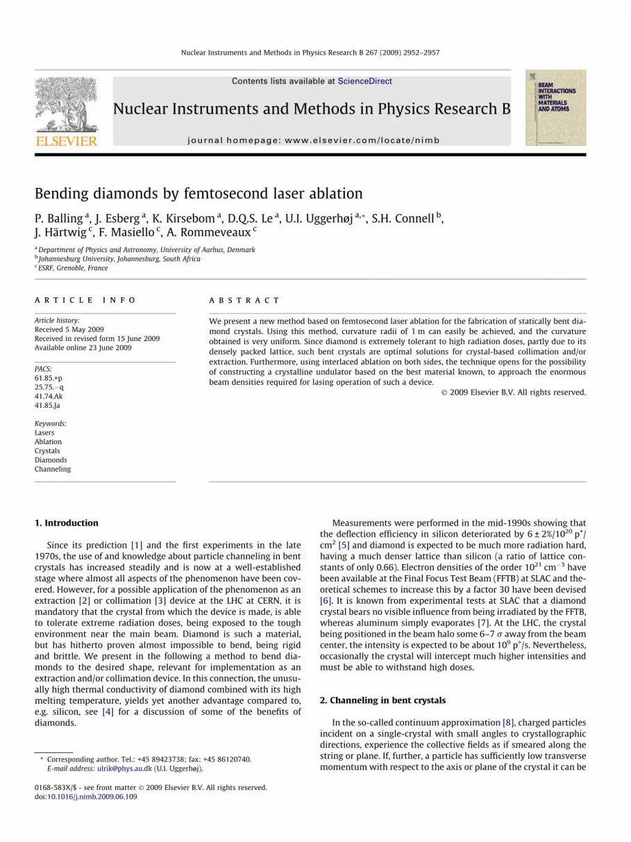
Fig. 1. Photographs of the two laser-ablated diamonds. The upper picture showsthe single trenched thin diamond (of approximate size 2.1 � 6.0 � 0.1 mm3) and thelower picture the thick diamond (of approximate size 2.5 � 6.9 � 0.3 mm3) withtrenches interlaced on opposite surfaces.
4. Laser ablation
Laser ablation by ultrashort pulses has been demonstrated as avery precise and versatile method for micromachining (for a recentoverview, see [34]). The short pulse duration minimizes heat trans-port during the laser pulse, which gives maximum resolution andminimal heat-induced damage to the surrounding material. Inaddition, the short pulses are even at moderate pulse energiesassociated with a high peak intensity, which means that all mate-rials can be excited and hence machined.
The ablation of dielectric materials – including materials trans-parent to the laser wavelength – is typically described by a process,in which material excitation by multi-photon or tunnel ionizationis followed by light absorption in the generated free (or conduc-tion-band) carriers. The laser-driven electrons may collisionallyionize other atoms, generating more and more free electrons inan avalanche process [35]. The process is thus not dependent onlinear absorption in the medium, but the ablation efficiency willdepend on the material parameters and foremost on the bandgap. Similarly, the efficiency depends on the laser wavelengthand on the pulse duration [36].
The present ablation experiments were carried out with achirped-pulse amplified Ti:Sapphire-based femtosecond laser sys-tem operated at a repetition rate of 1 kHz. The pulse duration is�100 fs and the central wavelength is 800 nm with pulse energiesup to �1 mJ. The light is focused by a 45 mm focal-lengthachromatic lens onto the diamond samples, which gives a calcu-lated laser spot size of 5.72 lm. As reported in detail elsewhere,the multi-shot laser ablation threshold of the diamond samples isdetermined to 0.9 ± 0.2 J/cm2 (or 9 � 1012 W/cm2) [37]. The sin-gle-shot ablation threshold is determined to be much larger thanthis value. This reflects the important phenomenon of incubation:Repeated irradiation of a dielectric by laser pulses will graduallychange the sample. Although the hot electron plasma from previ-ous pulses decays on a time scale which is much faster than theseparation between laser pulses, the excitation can leave thesample with trapped charged states (color centers) or defects,which can increase the absorption of subsequent pulses and henceincrease the ablation efficiency [35].
Fig. 1 shows photographs of the ablated surfaces of the two dia-mond crystals. The upper image shows the crystal that was ablatedon one side only to produce crystal bending, while the lower imageshows the surface of the diamond that was ablated interlaced, onboth sides to possibly generate a crystal undulator.
In the present investigation, the goal is to form grooves ortrenches on the single-crystal diamond surfaces. The trenches arerequired to be 10 lm wide and 10 lm deep for the crystalline und-
ulator and 15 lm wide and 25 lm deep for the bent crystal. It isfound that the best way to control the depth of the laser-writtentrenches without changing the width too much is to employ a fixedpulse energy slightly above the ablation threshold and simply ad-just the scanning speed. Depending on the requirements for thetrenches, pulse energies of 2 lJ or 20 lJ are employed, which cor-responds to peak intensities of 3.9 � 1013 W/cm2 and3.9 � 1014 W/cm2, respectively, or maximum fluences of 3.9 J/cm2
and 39 J/cm2. For the smallest pulse energy, this is roughly threetimes the multi-shot threshold fluence, but slightly below the sin-gle-shot threshold [37].
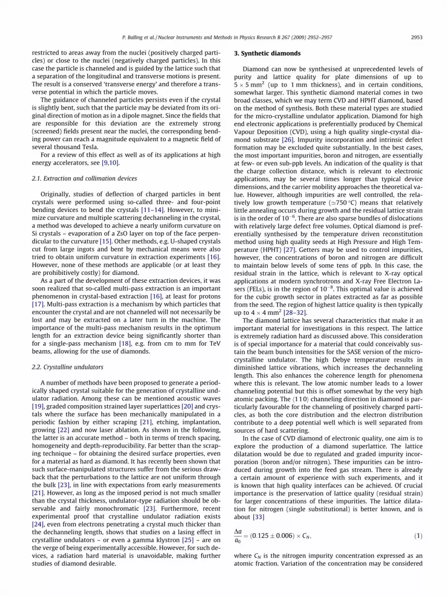
Fig. 2 shows scanning-electron microscope images of diamondsamples cleaved to expose the laser-cut trenches. In each image,the trenches are cut with fixed pulse energies, but the scan speedhas been changed between trenches, see the details in the figurecaption. With the calculated laser spot size from above, the scanspeeds can be seen to correspond to a fairly large overlap of pulses.For example for Fig. 2(b), the overlap (within two times the laserspot size) is 230, 290, 380, 570, and 1140 pulses. We thus expectincubation – i.e. the gradual decrease on the ablation thresholdwith increasing number of pulses – to be of significant importancein determining the material removal rate. Except for the highestscan speed, 0.05 mm/s, the average volume removal rate is moreor less insensitive to the scan rate and amounts to�1 � 10�5 mm3/s. For the highest speed, this number is somewhatsmaller, which may signify less incubation in this situation.
In order to produce the samples shown in Fig. 1, we used a pulseenergy of 2 lJ at a scan rate of 0.018 mm/s, roughly correspondingto the lower trench in Fig. 2(a). For the bent diamond, 20 lJ and ascan rate of 0.04 mm/s is employed. This corresponds to the secondtrench from the right in Fig. 2(b).
5. X-ray measurements
The radius of curvature of the ablated diamond crystals wasinvestigated by means of X-ray diffraction topography – an imag-ing technique based on Bragg diffraction. The experiment was per-formed at the beamlines BM05 and ID19 of the EuropeanSynchrotron Radiation Facility. An extended and homogeneous X-ray beam, impinging on the crystal, is diffracted and recorded ona two-dimensional detector, in this case a high resolution photo-graphic film. Local lattice plane bending may lead to focusing or
Fig. 2. Scanning-electron microscope images showing side views of laser-written trenches. Note the different scales in the two images (approx. 50 � 50 lm2 in left panel and500 � 500 lm2 in right panel). The laser is operated at fixed fluences of 3.9 J/cm2 (left panel) and 39 J/cm2 (right panel), while the scanning speed has been changed betweentrenches: 0.02 mm/s (left) and 0.010 mm/s (right). In right panel from left to right 0.05 mm/s, 0.01 mm/s, 0.02 mm/s, 0.03 mm/s, 0.04 mm/s, and again 0.05 mm/s.
P. Balling et al. / Nuclear Instruments and Methods in Physics Research B 267 (2009) 2952–2957 2955
defocusing effects. This is the case for dislocations [38], dynamicdeformation such as vibrations [39] and static deformation, e.g.created in a bonded wafer [40]. For a cylindrically bent crystal,the geometrical condition for meridional focusing of a polychro-matic radiation is [41,42]:
R ¼ 2cosðhB � aÞ
pþ cosðhB þ aÞ
q
� ��1
; ð2Þ
where R is the radius of curvature, a is the asymmetry angle, p is thesource to crystal distance and q is the crystal to focus distance. Insynchrotrons p� q and in this limit Eq. (2) simplifies and, for thesymmetrical case a = 0, we obtain
R ’ 2qcosðhBÞ
: ð3Þ
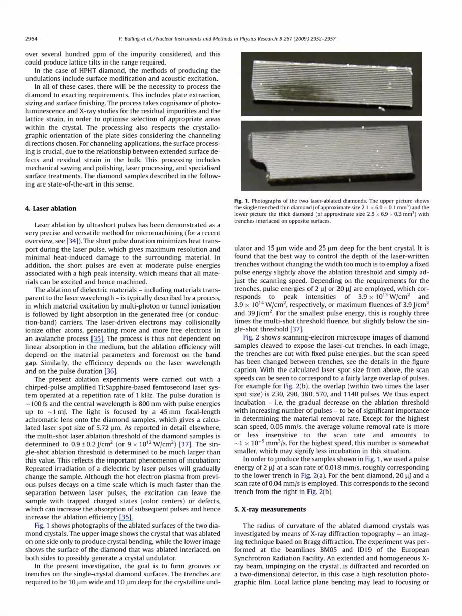
An X-ray topography of the two crystals has been recorded beforethe laser ablation, see Fig. 1, showing the quality of the syntheticdiamonds (Fig. 3).
After the laser ablation, to measure the possible focusing/defo-cusing effect due to the curvature of the diamond, a set of Laue(transmission) topographs at different distances was taken for bothdiamonds. An example of the measurements taken at 20, 30, 40, 50
Fig. 3. White beam X-ray topographs of the two diamonds before laser ablation: (a)single trenched and (b) double trenched diamond. Defects such as dislocations andstacking faults are clearly visible.
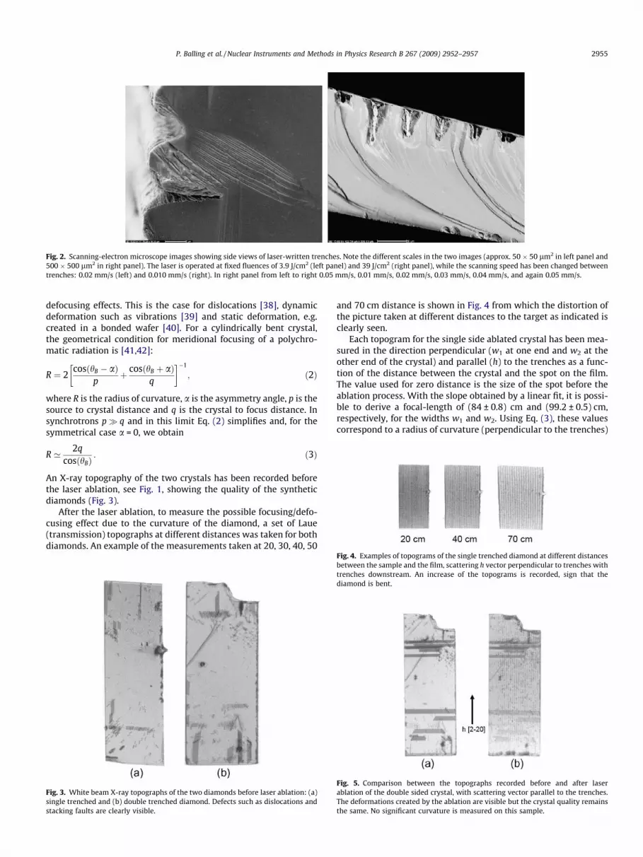
and 70 cm distance is shown in Fig. 4 from which the distortion ofthe picture taken at different distances to the target as indicated isclearly seen.
Each topogram for the single side ablated crystal has been mea-sured in the direction perpendicular (w1 at one end and w2 at theother end of the crystal) and parallel (h) to the trenches as a func-tion of the distance between the crystal and the spot on the film.The value used for zero distance is the size of the spot before theablation process. With the slope obtained by a linear fit, it is possi-ble to derive a focal-length of (84 ± 0.8) cm and (99.2 ± 0.5) cm,respectively, for the widths w1 and w2. Using Eq. (3), these valuescorrespond to a radius of curvature (perpendicular to the trenches)
Fig. 4. Examples of topograms of the single trenched diamond at different distancesbetween the sample and the film, scattering h vector perpendicular to trenches withtrenches downstream. An increase of the topograms is recorded, sign that thediamond is bent.
Fig. 5. Comparison between the topographs recorded before and after laserablation of the double sided crystal, with scattering vector parallel to the trenches.The deformations created by the ablation are visible but the crystal quality remainsthe same. No significant curvature is measured on this sample.
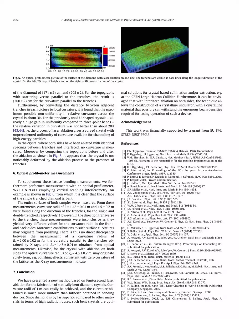
Fig. 6. An optical profilometer picture of the surface of the diamond with laser ablation on one side. The trenches are visible as dark lines along the longest direction of thecrystal. On the left, 2D map of heights and on the right, a 3D reconstruction of the crystal.
2956 P. Balling et al. / Nuclear Instruments and Methods in Physics Research B 267 (2009) 2952–2957
of the diamond of (171 ± 2) cm and (202 ± 2). For the topographswith scattering vector parallel to the trenches, the result is(200 ± 2) cm for the curvature parallel to the trenches.
Furthermore, by converting the distance between adjacenttrenches in each picture to local curvature, it is found that the max-imum possible non-uniformity in relative curvature across thecrystal is about 3%. For the previously used U-shaped crystals – al-ready a huge gain in uniformity compared to three-point bends –the relative variation in curvature was not better than about 20%[43,44], i.e. the process of laser ablation gives a curved crystal withunprecedented uniformity of curvature available for channeling ofhigh-energy particles.
In the crystal where both sides have been ablated with identicalspacings between trenches and interlaced, no curvature is mea-sured. Moreover by comparing the topographs before and afterthe ablation as shown in Fig. 5, it appears that the crystal is notnoticeably deformed by the ablation process or the presence oftrenches.
6. Optical profilometer measurements
To supplement these lattice bending measurements, we fur-thermore performed measurements with an optical profilometer,WYKO NT9300, employing vertical scanning interferometry. Anexample is shown in Fig. 6 from which it is clear that the surfaceof the single trenched diamond is bent.
The entire surfaces of both samples were measured. From thesemeasurements, curvature radii of R = 1.48 ± 0.01 m and 4.5 ± 0.2 mwere found along the direction of the trenches, for the single anddouble trenched, respectively. However, in the direction transverseto the trenches, these measurements were inconclusive as theyyielded very different values for the curvature radii in the front-and back-sides. Moreover, contributions to such surface curvaturesmay originate from polishing. There is thus no direct discrepancybetween the measurement of a curvature radius ofRx = 2.00 ± 0.02 m for the curvature parallel to the trenches ob-tained by X-rays, and Ro = 1.48 ± 0.01 m obtained from opticalmeasurements. Likewise, for the crystal with ablation on bothsides, the optical curvature radius of Ro = 4.5 ± 0.2 m, may originatesolely from, e.g. polishing effects, consistent with zero curvature ofthe lattice, as the X-ray measurements indicate.
7. Conclusion
We have presented a new method based on femtosecond laserablation for the fabrication of statically bent diamond crystals. Cur-vature radii of 1 m can easily be achieved, and the curvature ob-tained is much more uniform than hitherto obtained in bendingdevices. Since diamond is by far superior compared to other mate-rials in terms of high radiation doses, such bent crystals are opti-
mal solutions for crystal-based collimation and/or extraction, e.g.at the CERN Large Hadron Collider. Furthermore, it can be envis-aged that with interlaced ablation on both sides, the technique al-lows the construction of a crystalline undulator, with a crystallinematerial that possibly can withstand the enormous beam densitiesrequired for lasing operation of such a device.
Acknowledgement
This work was financially supported by a grant from EU FP6,STREP-NEST PECU.
References
[1] E.N. Tsyganov, Fermilab TM-682, TM-684, Batavia, 1976, Unpublished.[2] E. Uggerhøj, U.I. Uggerhøj, Nucl. Instr. and Meth. B 234 (2005) 31.[3] V.M. Biryukov, in: R.A. Carrigan, N.A. Mokhov (Eds.), FERMILAB-Conf-98/166,
1998 (R. Assmann is the responsible for the possible implementation at theLHC).
[4] U.I. Uggerhøj, J.P.F. Sellschop, Phys. Rev. ST Accel. Beams 5 (2002) 073501.[5] C. Biino et al., in: Proceedings of the Fifth European Particle Accelerator
Conference, Sitges, Spain, 1997, p. 2385.[6] P. Emma, R. Iverson, P. Krejcik, P. Raimondi, J. Safranek, SLAC-PUB-8850, 2001.[7] P. Krejcik, 2001, Private Communication.[8] J. Lindhard, Mat. Fys. Medd. Dan. Vid. Selsk. 34 (1965) 1.[9] A. Baurichter et al., Nucl. Instr. and Meth. B 164–165 (2000) 27.
[10] S.P. Møller et al., Nucl. Instr. and Meth. B 84 (1994) 434.[11] A.S. Vodop’yanov et al., Sov. Phys. JETP Lett. 30 (1979) 442;
A.F. Elishev et al., Phys. Lett. B 88 (1979) 387.[12] J.F. Bak et al., Phys. Lett. B 93 (1980) 505.[13] S.I. Baker et al., Phys. Lett. B 137 (1984) 129.[14] W.M. Gibson et al., Nucl. Instr. and Meth. B 2 (1984) 54.[15] J.S. Forster et al., Nucl. Phys. B 318 (1989) 301.[16] X. Altuna et al., Phys. Lett. B 357 (1995) 671.[17] G. Arduini et al., Phys. Rev. Lett. 79 (1997) 4182.[18] A.G. Afonin et al., Phys. Rev. Lett. 87 (2001) 094802.[19] A.V. Korol, A.V. Solov’yov, W. Greiner, J. Phys. G: Nucl. Part. Phys. 24 (1998)
L45.[20] U. Mikkelsen, E. Uggerhøj, Nucl. Instr. and Meth. B 160 (2000) 435.[21] S. Bellucci et al., Phys. Rev. ST Accel. Beams 7 (2004) 023501.[22] V. Guidi et al., Appl. Phys. Lett. 90 (2007) 114107.[23] A. Kostyuk, A.V. Korol, A.V. Solov’yov, W. Greiner, Nucl. Instr. and Meth. B 266
(2008) 972.[24] H. Backe et al., in: Sultan Dabagov (Ed.), Proceedings of Channeling 08,
submitted for publication.[25] A. Kostyuk, A.V. Korol, A.V. Solov’yov, W. Greiner, J. Phys. G 36 (2009) 025107.[26] J. Isberg et al., Science 297 (2002) 1670.[27] R.C. Burns et al., Diam. Relat. Mater. 8 (1999) 1433.[28] J.P.F. Sellschop et al., New Diam. Front. Carbon Technol. 10 (2000) 256.[29] J. Hoszowska et al., J. Phys. D – Appl. Phys. 34 (2001) A47.[30] A.K. Freund, J. Hoszowska, J.P.F. Sellschop, R.C. Burns, M. Rebak, Nucl. Instr. and
Meth. A 467 (2001) 384.[31] J.P.F. Sellschop, A. Freund, J. Hoszowska, S.H. Connell, M. Rebak, R.C. Burns,
Phys. Stat. Solidi A 193 (2002) 415.[32] R.C. Burnsa et al., Diam. Relat. Mater., submitted for publication.[33] W.L. Bragg, W.H. Bragg, Proc. Royal Soc. (Lond.) 89A (1913) 277.[34] P. Balling, in: D.M. Kane (Ed.), Laser Cleaning II, World Scientific Publishing
Company, Singapore, 2006.[35] D. Bäuerle, Laser Processing and Chemistry, third ed., Springer, 2000.[36] B.H. Christensen, P. Balling, Phys. Rev. B 79 (2009) 155424.[37] J. Byskov-Nielsen, D.Q.S. Le, B.H. Christensen, P. Balling, Appl. Phys. A,
submitted for publication.
P. Balling et al. / Nuclear Instruments and Methods in Physics Research B 267 (2009) 2952–2957 2957
[38] F. Zontone et al., J. Synchrotr. Radiat. 3 (1996) 173.[39] I. Matsouli et al., J. Phys. D: Appl. Phys. 31 (1998) 1478.[40] J. Härtwig et al., Cryst. Res. Technol. 37 (2002) 705.[41] V. Mocella et al., J. Appl. Crystallogr. 37 (2004) 941.
[42] G. Rosenbaum, K.C. Holmes, in: H. Winick, S. Doniach (Eds.), SynchrotronRadiation Research, Plenum Press, 1980.
[43] J. Klem, U. Mikkelsen, CERN SL-MD-Note-171, 1995, Unpublished.[44] A. Baurichter et al., Nucl. Instr. and Meth. B 119 (1996) 172.