100
CPI installation system
| Date post: | 13-Mar-2023 |
| Category: |
Documents |
| Upload: | khangminh22 |
| View: | 0 times |
| Download: | 0 times |
CPI installation system
Products 2008 – Subject to change – 2007/104 / 4.6-2
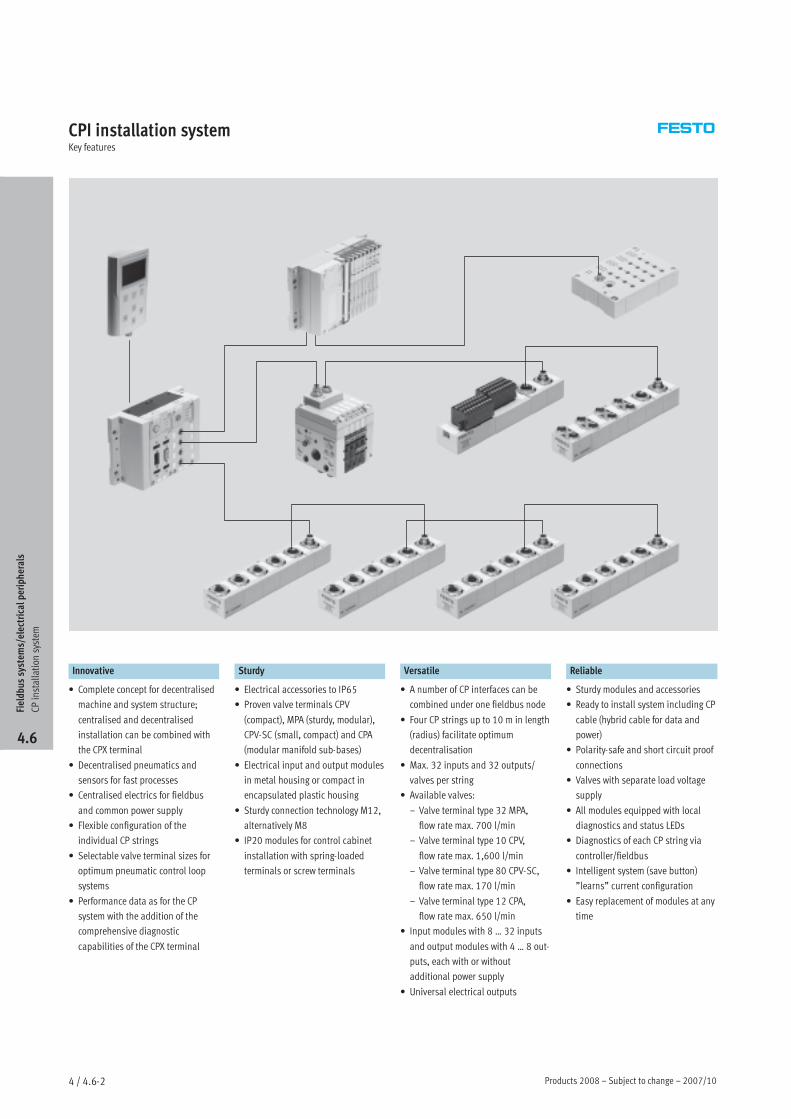
CPI installation systemKey features
Innovative Sturdy Versatile Reliable
• Complete concept for decentralised
machine and system structure;
centralised and decentralised
installation can be combined with
the CPX terminal
• Decentralised pneumatics and
sensors for fast processes
• Centralised electrics for fieldbus
and common power supply
• Flexible configuration of the
individual CP strings
• Selectable valve terminal sizes for
optimum pneumatic control loop
systems
• Performance data as for the CP
system with the addition of the
comprehensive diagnostic
capabilities of the CPX terminal
• Electrical accessories to IP65
• Proven valve terminals CPV
(compact), MPA (sturdy, modular),
CPV-SC (small, compact) and CPA
(modular manifold sub-bases)
• Electrical input and output modules
in metal housing or compact in
encapsulated plastic housing
• Sturdy connection technology M12,
alternatively M8
• IP20 modules for control cabinet
installation with spring-loaded
terminals or screw terminals
• A number of CP interfaces can be
combined under one fieldbus node
• Four CP strings up to 10 m in length
(radius) facilitate optimum
decentralisation
• Max. 32 inputs and 32 outputs/
valves per string
• Available valves:
– Valve terminal type 32 MPA,
flow rate max. 700 l/min
– Valve terminal type 10 CPV,
flow rate max. 1,600 l/min
– Valve terminal type 80 CPV-SC,
flow rate max. 170 l/min
– Valve terminal type 12 CPA,
flow rate max. 650 l/min
• Input modules with 8 … 32 inputs
and output modules with 4 … 8 out-
puts, each with or without
additional power supply
• Universal electrical outputs
• Sturdy modules and accessories
• Ready to install system including CP
cable (hybrid cable for data and
power)
• Polarity-safe and short circuit proof
connections
• Valves with separate load voltage
supply
• All modules equipped with local
diagnostics and status LEDs
• Diagnostics of each CP string via
controller/fieldbus
• Intelligent system (save button)
”learns” current configuration
• Easy replacement of modules at any
time
Fieldbus
system
s/electricalperiph
erals
CPinstallation
system
4.6
2007/10 – Subject to change – Products 2008 4 / 4.6-3
CPI installation systemKey features
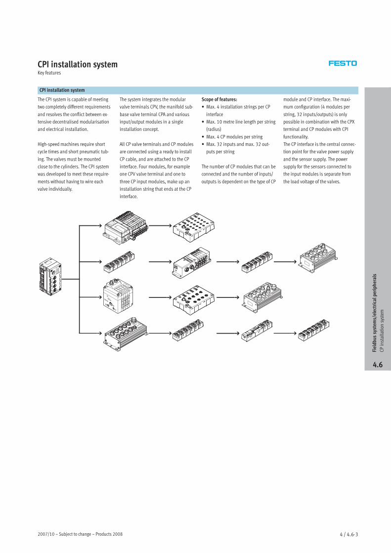
CPI installation system
The CPI system is capable of meeting
two completely different requirements
and resolves the conflict between ex-
tensive decentralised modularisation
and electrical installation.
High-speed machines require short
cycle times and short pneumatic tub-
ing. The valves must be mounted
close to the cylinders. The CPI system
was developed to meet these require-
ments without having to wire each
valve individually.
The system integrates the modular
valve terminals CPV, the manifold sub-
base valve terminal CPA and various
input/output modules in a single
installation concept.
All CP valve terminals and CP modules
are connected using a ready to install
CP cable, and are attached to the CP
interface. Four modules, for example
one CPV valve terminal and one to
three CP input modules, make up an
installation string that ends at the CP
interface.
Scope of features:
• Max. 4 installation strings per CP
interface
• Max. 10 metre line length per string
(radius)
• Max. 4 CP modules per string
• Max. 32 inputs and max. 32 out-
puts per string
The number of CP modules that can be
connected and the number of inputs/
outputs is dependent on the type of CP
module and CP interface. The maxi-
mum configuration (4 modules per
string, 32 inputs/outputs) is only
possible in combination with the CPX
terminal and CP modules with CPI
functionality.
The CP interface is the central connec-
tion point for the valve power supply
and the sensor supply. The power
supply for the sensors connected to
the input modules is separate from
the load voltage of the valves.
Fieldbus
system
s/electricalperiph
erals
CPinstallation
system
4.6
Products 2008 – Subject to change – 2007/104 / 4.6-4
CPI installation systemKey features
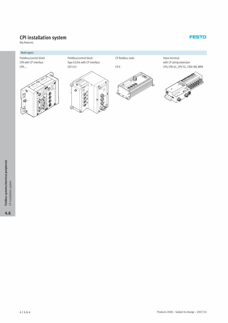
Node types:
Fieldbus/control block
CPX with CP interface
CPX-…
Fieldbus/control block
Type 03/04 with CP interface
ISF3-03
CP fieldbus node
CP-E
Valve terminal
with CP string extension
CPV, CPA-SC, CPV-SC, CDVI-DN, MPA
Fieldbus
system
s/electricalperiph
erals
CPinstallation
system
4.6
2008/06 – Subject to change 5 Internet: www.festo.com/catalogue/...
CPI installation systemOrdering system
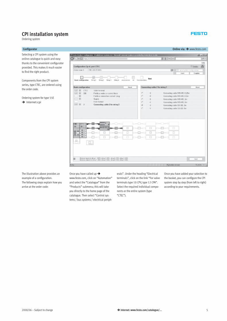
Configurator Online via: www.festo.com
Selecting a CPI system using the
online catalogue is quick and easy
thanks to the convenient configurator
provided. This makes it much easier
to find the right product.
Components from the CPI system
series, type CTEC, are ordered using
the order code.
Ordering system for type 55E
Internet:cpi
The illustration above provides an
example of a configuration.
The following steps explain how you
arrive at the order code:
Once you have called up
www.festo.com, click on “Automation”
and select the “Catalogue” from the
“Products” submenu; this will take
you directly to the home page of the
catalogue. Then select “Control sys-
tems / bus systems / electrical periph-
erals”. Under the heading “Electrical
terminals”, click on the link “For valve
terminals type 10 CPV, type 12 CPA”.
Select the required individual compo-
nents or the entire system (type
“CTEC”).
Once you have added your selection to
the basket, you can configure the CPI
system step by step (from left to right)
according to your requirements.
Subject to change – 2008/066 Internet: www.festo.com/catalogue/...
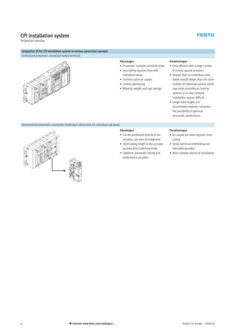
CPI installation systemPeripherals overview
Integration of the CPI installation system in various connection concepts
Centralised pneumatic connection (valve terminal)
Advantages
• Pneumatic multiple connector plate
• Less tubing required than with
individual valves
• Common valve air supply
• Central positioning
• Material, weight and cost savings
Disadvantages
• Only effective with a large number
of closely spaced actuators
• Heavier than an individual valve
(lower overall weight than the same
number of individual valves), which
may make assembly on moving
systems or in very cramped
installation spaces difficult
• Longer tube lengths are
occasionally required, ruling out
the possibility of optimum
pneumatic performance
Decentralised pneumatic connection (individual valve/valve on individual sub-base)
Advantages
• Can be positioned directly at the
actuator, can even be integrated
• Short tubing length to the actuator
enables short switching times
• Optimum pneumatic timing and
performance possible
Disadvantages
• Air supply per valve requires more
tubing
• Serial electrical interlinking not
advisable/possible
• More complex electrical installation
2008/06 – Subject to change 7 Internet: www.festo.com/catalogue/...
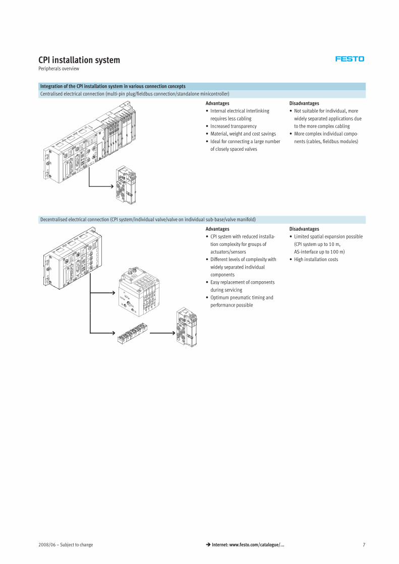
CPI installation systemPeripherals overview
Integration of the CPI installation system in various connection concepts
Centralised electrical connection (multi-pin plug/fieldbus connection/standalone minicontroller)
Advantages
• Internal electrical interlinking
requires less cabling
• Increased transparency
• Material, weight and cost savings
• Ideal for connecting a large number
of closely spaced valves
Disadvantages
• Not suitable for individual, more
widely separated applications due
to the more complex cabling
• More complex individual compo-
nents (cables, fieldbus modules)
Decentralised electrical connection (CPI system/individual valve/valve on individual sub-base/valve manifold)
Advantages
• CPI system with reduced installa-
tion complexity for groups of
actuators/sensors
• Different levels of complexity with
widely separated individual
components
• Easy replacement of components
during servicing
• Optimum pneumatic timing and
performance possible
Disadvantages
• Limited spatial expansion possible
(CPI system up to 10 m,
AS-interface up to 100 m)
• High installation costs
Subject to change – 2008/068 Internet: www.festo.com/catalogue/...
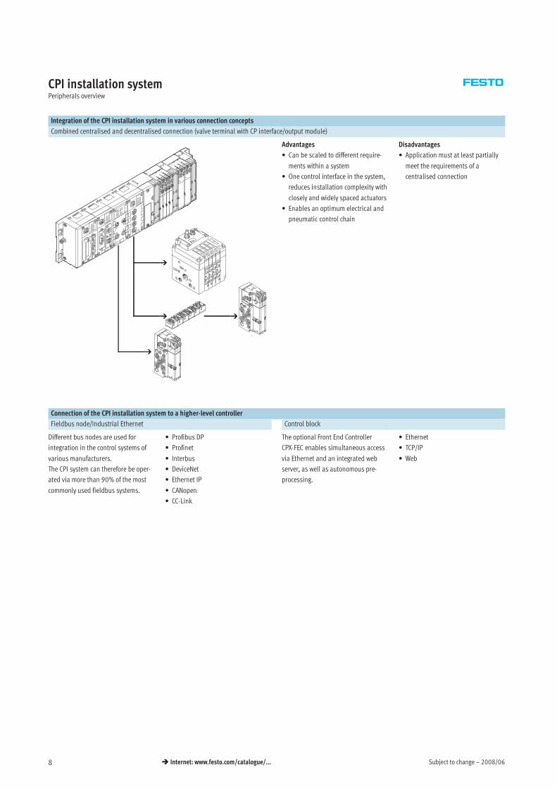
CPI installation systemPeripherals overview
Integration of the CPI installation system in various connection concepts
Combined centralised and decentralised connection (valve terminal with CP interface/output module)
Advantages
• Can be scaled to different require-
ments within a system
• One control interface in the system,
reduces installation complexity with
closely and widely spaced actuators
• Enables an optimum electrical and
pneumatic control chain
Disadvantages
• Application must at least partially
meet the requirements of a
centralised connection
Connection of the CPI installation system to a higher-level controller
Fieldbus node/Industrial Ethernet Control block
Different bus nodes are used for
integration in the control systems of
various manufacturers.
The CPI system can therefore be oper-
ated via more than 90% of the most
commonly used fieldbus systems.
• Profibus DP
• Profinet
• Interbus
• DeviceNet
• Ethernet IP
• CANopen
• CC-Link
The optional Front End Controller
CPX-FEC enables simultaneous access
via Ethernet and an integrated web
server, as well as autonomous pre-
processing.
• Ethernet
• TCP/IP
• Web
2008/06 – Subject to change 9 Internet: www.festo.com/catalogue/...
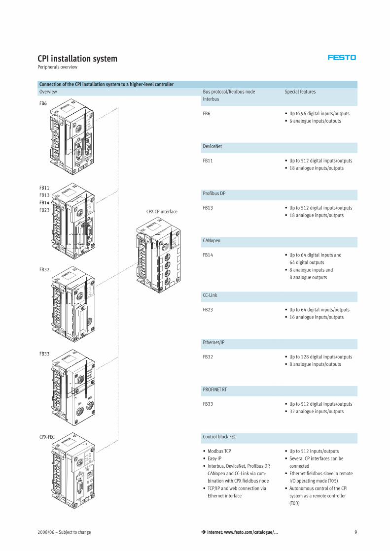
CPI installation systemPeripherals overview
Connection of the CPI installation system to a higher-level controller
Overview Bus protocol/fieldbus node Special features
FB6Interbus
FB6
FB6 • Up to 96 digital inputs/outputs
• 6 analogue inputs/outputs
DeviceNet
FB11
FB11 • Up to 512 digital inputs/outputs
• 18 analogue inputs/outputs
FB11
FB13 Profibus DP
FB14
CPX CP interface
FB14
FB23 FB13 • Up to 512 digital inputs/outputs
• 18 analogue inputs/outputs
CANopen
FB32
FB14 • Up to 64 digital inputs and
64 digital outputs
• 8 analogue inputs and
8 analogue outputs
CC-Link
FB23 • Up to 64 digital inputs/outputs
• 16 analogue inputs/outputs
Ethernet/IP
FB33FB33FB32 • Up to 128 digital inputs/outputs
• 8 analogue inputs/outputs
PROFINET RT
FB33 • Up to 512 digital inputs/outputs
• 32 analogue inputs/outputs
CPX-FEC Control block FEC
• Modbus TCP
• Easy-IP
• Interbus, DeviceNet, Profibus DP,
CANopen and CC-Link via com-
bination with CPX fieldbus node
• TCP/IP and web connection via
Ethernet interface
• Up to 512 inputs/outputs
• Several CP interfaces can be
connected
• Ethernet fieldbus slave in remote
I/O operating mode (T05)
• Autonomous control of the CPI
system as a remote controller
(T03)
Subject to change – 2008/0610 Internet: www.festo.com/catalogue/...
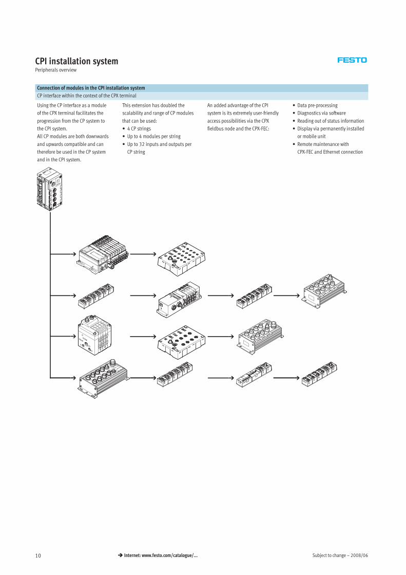
CPI installation systemPeripherals overview
Connection of modules in the CPI installation system
CP interface within the context of the CPX terminal
Using the CP interface as a module
of the CPX terminal facilitates the
progression from the CP system to
the CPI system.
All CP modules are both downwards
and upwards compatible and can
therefore be used in the CP system
and in the CPI system.
This extension has doubled the
scalability and range of CP modules
that can be used:
• 4 CP strings
• Up to 4 modules per string
• Up to 32 inputs and outputs per
CP string
An added advantage of the CPI
system is its extremely user-friendly
access possibilities via the CPX
fieldbus node and the CPX-FEC:
• Data pre-processing
• Diagnostics via software
• Reading out of status information
• Display via permanently installed
or mobile unit
• Remote maintenance with
CPX-FEC and Ethernet connection
2008/06 – Subject to change 11 Internet: www.festo.com/catalogue/...
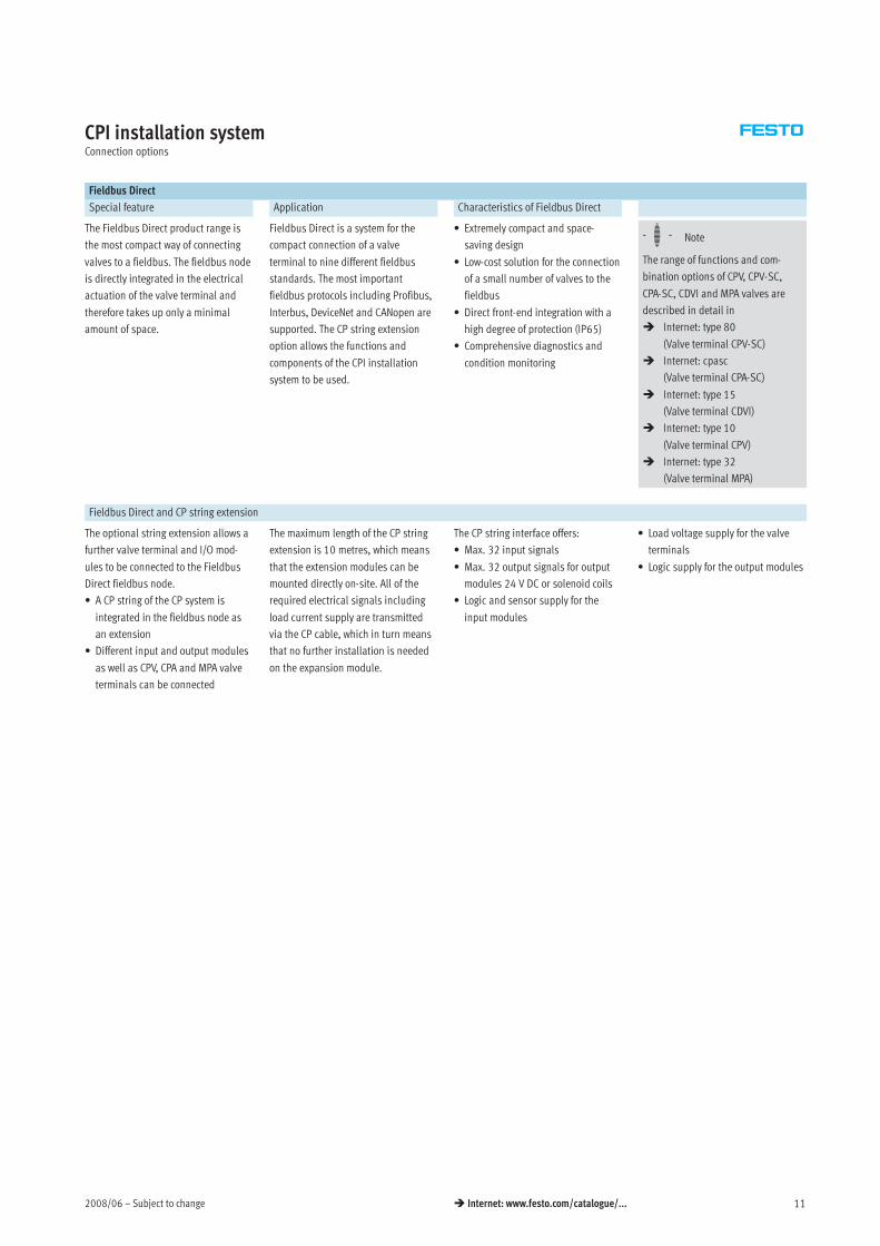
CPI installation systemConnection options
Fieldbus Direct
Special feature Application Characteristics of Fieldbus Direct
The Fieldbus Direct product range is
the most compact way of connecting
valves to a fieldbus. The fieldbus node
is directly integrated in the electrical
actuation of the valve terminal and
therefore takes up only a minimal
amount of space.
Fieldbus Direct is a system for the
compact connection of a valve
terminal to nine different fieldbus
standards. The most important
fieldbus protocols including Profibus,
Interbus, DeviceNet and CANopen are
supported. The CP string extension
option allows the functions and
components of the CPI installation
system to be used.
• Extremely compact and space-
saving design
• Low-cost solution for the connection
of a small number of valves to the
fieldbus
• Direct front-end integration with a
high degree of protection (IP65)
• Comprehensive diagnostics and
condition monitoring
-H- Note
The range of functions and com-
bination options of CPV, CPV-SC,
CPA-SC, CDVI and MPA valves are
described in detail in
Internet: type 80
(Valve terminal CPV-SC)
Internet: cpasc
(Valve terminal CPA-SC)
Internet: type 15
(Valve terminal CDVI)
Internet: type 10
(Valve terminal CPV)
Internet: type 32
(Valve terminal MPA)
Fieldbus Direct and CP string extension
The optional string extension allows a
further valve terminal and I/O mod-
ules to be connected to the Fieldbus
Direct fieldbus node.
• A CP string of the CP system is
integrated in the fieldbus node as
an extension
• Different input and output modules
as well as CPV, CPA and MPA valve
terminals can be connected
The maximum length of the CP string
extension is 10 metres, which means
that the extension modules can be
mounted directly on-site. All of the
required electrical signals including
load current supply are transmitted
via the CP cable, which in turn means
that no further installation is needed
on the expansion module.
The CP string interface offers:
• Max. 32 input signals
• Max. 32 output signals for output
modules 24 V DC or solenoid coils
• Logic and sensor supply for the
input modules
• Load voltage supply for the valve
terminals
• Logic supply for the output modules
Subject to change – 2008/0612 Internet: www.festo.com/catalogue/...
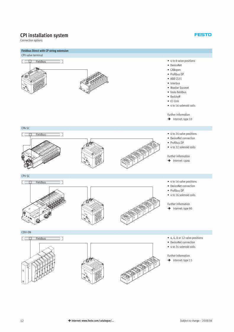
CPI installation systemConnection options
Fieldbus Direct with CP string extension
CPV valve terminal
Fieldbus • 4 to 8 valve positions
• DeviceNet
• CANopen
• Profibus DP
• ABB CS31
• Interbus
• Moeller Suconet
• Festo fieldbus
• Beckhoff
• CC-Link
• 4 to 16 solenoid coils
Further information
Internet: type 10
CPA-SC
Fieldbus • 4 to 24 valve positions
• DeviceNet connection
• Profibus DP
• 4 to 32 solenoid coils
Further information
Internet: cpasc
CPV-SC
Fieldbus • 4 to 16 valve positions
• DeviceNet connection
• Profibus DP
• 4 to 16 solenoid coils
Further information
Internet: type 80
CDVI-DN
In
Out
1
3
5
7
0
2
4
6
Fieldbus • 4, 6, 8 or 12 valve positions
• DeviceNet connection
• 4 to 24 solenoid coils
Further information
Internet: type 15
2008/06 – Subject to change 13 Internet: www.festo.com/catalogue/...
CPI installation systemConnection options
Positioning systems
Application Properties
The SPC200 is a position controller
(closed loop) and positioning control
(open loop) in one. Together with the
drive, the displacement encoder and
the proportional directional control
valve, it forms a closed control loop.
The CP interface option enables the
functions and components of the CP
installation system to be used.
• Modular with 9 different plug-in
cards
• Wide variety with up to 4 position-
ing axes, stepper motor axes and
the option of operating pneumatic
and electrical systems
• Flexible with set selection for
positioning tasks with fixed
trajectories and program mode
with up to 100 programs
• Quick commissioning using the
WINPISA diagnostic and
programming tool
Positioning systems and CP interface
The plug-in cards for connecting the
axis strings facilitate the connection
of further input/output modules:
• One CP string of the CP system is
possible as an extension
The maximum length of the CP string
extension is 10 metres, which means
that the extension modules can be
mounted directly on-site. All of the
required electrical signals including
The CP string interface offers:
• 16 input signals
• 16 output signals for output
modules 24 V DC or solenoid coils
• Logic and sensor supply for the
-H- Note
CP input modules can only be
connected via a terminating resistor
(KZW-M9-R100).possible as an extension
• Various input and output modules
as well as CPV valve terminals can
be connected
required electrical signals including
load current supply are transmitted
via the CP cable, which in turn means
that no further installation is needed
on the extension module.
Logic and sensor supply for the
input modules
• Load voltage supply for the valve
terminals
• Logic supply for the output modules
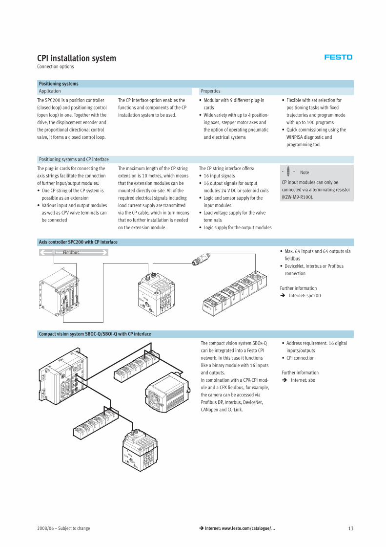
Axis controller SPC200 with CP interface
In
Out
1
3
5
7
0
2
4
6
Fieldbus • Max. 64 inputs and 64 outputs via
fieldbus
• DeviceNet, Interbus or Profibus
connection
Further information
Internet: spc200
Compact vision system SBOC-Q/SBOI-Q with CP interface
The compact vision system SBOx-Q
can be integrated into a Festo CPI
network. In this case it functions
like a binary module with 16 inputs
and outputs.
In combination with a CPX-CPI mod-
ule and a CPX fieldbus, for example,
the camera can be accessed via
Profibus DP, Interbus, DeviceNet,
CANopen and CC-Link.
• Address requirement: 16 digital
inputs/outputs
• CPI connection
Further information
Internet: sbo
Subject to change – 2008/0614 Internet: www.festo.com/catalogue/...
CPI installation systemConnection options
Connection of input and output modules in the CPI installation system
CP connecting cable
KVI-CP-3-… • Pre-assembled cables for
connecting the CP modules
Further information
Internet: kvi-cp
-H- Note
The total length of all CP cables in a
CP string must not exceed 10 m.
connecting the CP modules
• Lengths from 0.25 to 8 metres
• M9 plug/socket, 5-pin
• Straight/angled version in any
combination
Internet: kvi-cp
CP input/output modules in sturdy, universal and compact design or as a valve terminal
The connection technology for the
sensors and additional actuators
offers a wide range of digital and
analogue input and output modules
and is freely selectable – depending
on your standard or application:
• M12-5PIN
• M8-3PIN
• M8-4PIN
• Spring-loaded terminal or screw
terminal technology
The maximum number of inputs/
outputs that can be connected to
the individual modules can vary
depending on the application. The
following module sizes are
available:
• Input modules with 8, 16 or
32 channels
• Output modules with 4 or
8 channels
• CPV with 4, 6 or 8 valve slices
(max. 16 valves)
• MPA with 2 … 32 valves
• CPV-SC with 4 … 16 valves
• CPA with 2 … 16 valves
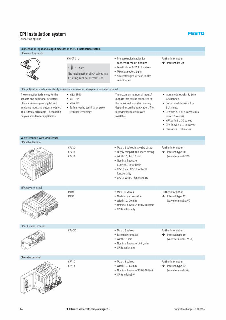
Valve terminals with CP interface
CPV valve terminal
CPV10
CPV14
CPV18
• Max. 16 valves in 8 valve slices
• Highly compact and space-saving
• Width 10, 14, 18 mm
• Nominal flow rate
400/800/1600 l/min
• CPV10 and CPV14 with CPI
functionality
• CPV18 with CP functionality
Further information
Internet: type 10
(Valve terminal CPV)
MPA valve terminal
MPA1
MPA2
• Max. 32 valves
• Modular and versatile
• Width 10, 20 mm
• Nominal flow rate 360/700 l/min
• CPI functionality
Further information
Internet: type 32
(Valve terminal MPA)
CPV-SC valve terminal
CPV-SC • Max. 16 valves
• Extremely compact
• Width 10 mm
• Nominal flow rate 170 l/min
• CPI functionality
Further information
Internet: type 80
(Valve terminal CPV-SC)
CPA valve terminal
CPA10
CPA14
• Max. 16 valves
• Width 10, 14 mm
• Nominal flow rate 300/600 l/min
• CP functionality
Further information
Internet: type 12
(Valve terminal CPA)
2008/06 – Subject to change 15 Internet: www.festo.com/catalogue/...
CPI installation systemKey features – Input/output modules
Connection of input and output modules in the CPI installation system
Special features of the CP input/output modules of sturdy design
The sturdy CP input/output modules
have a highly resistant aluminium
housing and its internal electronic
components can be repaired or
replaced.
As a CP-E…Z or output modules they
have a separate load voltage supply,
which means less load on the CP inter-
face and CP cable and more power for
the connected consuming devices.
This also facilitates separate discon-
nection of the consuming devices.
High degree of protection (IP65),
surpassed only by the compact CP
modules with IP65/67 protection. The
only exception is the IP20 protection
offered by the module with clamped
terminal connection for installation in
control cabinets.
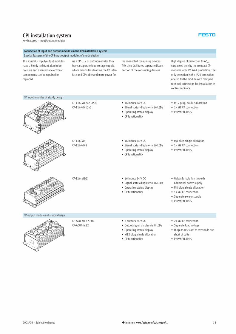
CP input modules of sturdy design
CP-E16-M12x2-5POL
CP-E16N-M12x2
• 16 inputs 24 V DC
• Signal status display via 16 LEDs
• Operating status display
• CP functionality
• M12 plug, double allocation
• 1x M9 CP connection
• PNP/NPN, IP65
CP-E16-M8
CP-E16N-M8
• 16 inputs 24 V DC
• Signal status display via 16 LEDs
• Operating status display
• CP functionality
• M8 plug, single allocation
• 1x M9 CP connection
• PNP/NPN, IP65
CP-E16-M8-Z • 16 inputs 24 V DC
• Signal status display via 16 LEDs
• Operating status display
• CP functionality
• Galvanic isolation through
additional power supply
• M8 plug, single allocation
• 1x M9 CP connection
• Separate sensor supply
• PNP/NPN, IP65
CP output modules of sturdy design
CP-A08-M12-5POL
CP-A08N-M12
• 8 outputs 24 V DC
• Output signal display via 8 LEDs
• Operating status display
• M12 plug, single allocation
• CP functionality
• 2x M9 CP connection
• Separate load voltage
• Outputs resistant to overloads and
short circuits
• PNP/NPN, IP65
Subject to change – 2008/0616 Internet: www.festo.com/catalogue/...
CPI installation systemKey features – Input/output modules
Connection of input and output modules in the CPI installation system
Special features of the CP input/output modules of economical design
In addition to the sturdy CP input/
output modules and the compact CP
input/output modules, there are also
the economical modules with the de-
sign features of the compact modules,
but with a greater number of inputs/
outputs.
The economical CP modules feature a
compact design, coupled with a large
number of inputs/outputs.
The modules can be used in
connection with the following valve
terminals:
– CPV, MPA, CPV-SC, CPA-SC, CDVI,
CPA
Application:
• Same function, configuration and
commissioning as sturdy or
compact CP modules
• Integrated H-rail mounting and
earthing plate
• Centrally placed status and
diagnostic LEDs
• The economical CP modules and
the other CP modules can be
operated together on a string
• The maximum number of modules
per CP string is as follows:
– CPI system: max. 4 modules or
max. 32 inputs and 32 outputs
– CP system: one valve terminal/
output module and one input
module
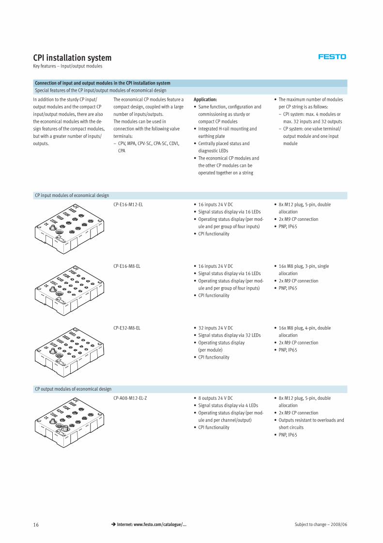
CP input modules of economical design
CP-E16-M12-EL • 16 inputs 24 V DC
• Signal status display via 16 LEDs
• Operating status display (per mod-
ule and per group of four inputs)
• CPI functionality
• 8x M12 plug, 5-pin, double
allocation
• 2x M9 CP connection
• PNP, IP65
CP-E16-M8-EL • 16 inputs 24 V DC
• Signal status display via 16 LEDs
• Operating status display (per mod-
ule and per group of four inputs)
• CPI functionality
• 16x M8 plug, 3-pin, single
allocation
• 2x M9 CP connection
• PNP, IP65
CP-E32-M8-EL • 32 inputs 24 V DC
• Signal status display via 32 LEDs
• Operating status display
(per module)
• CPI functionality
• 16x M8 plug, 4-pin, double
allocation
• 2x M9 CP connection
• PNP, IP65
CP output modules of economical design
CP-A08-M12-EL-Z • 8 outputs 24 V DC
• Signal status display via 4 LEDs
• Operating status display (per mod-
ule and per channel/output)
• CPI functionality
• 8x M12 plug, 5-pin, double
allocation
• 2x M9 CP connection
• Outputs resistant to overloads and
short circuits
• PNP, IP65
2008/06 – Subject to change 17 Internet: www.festo.com/catalogue/...
CPI installation systemKey features – Input/output modules
Connection of input and output modules in the CPI installation system
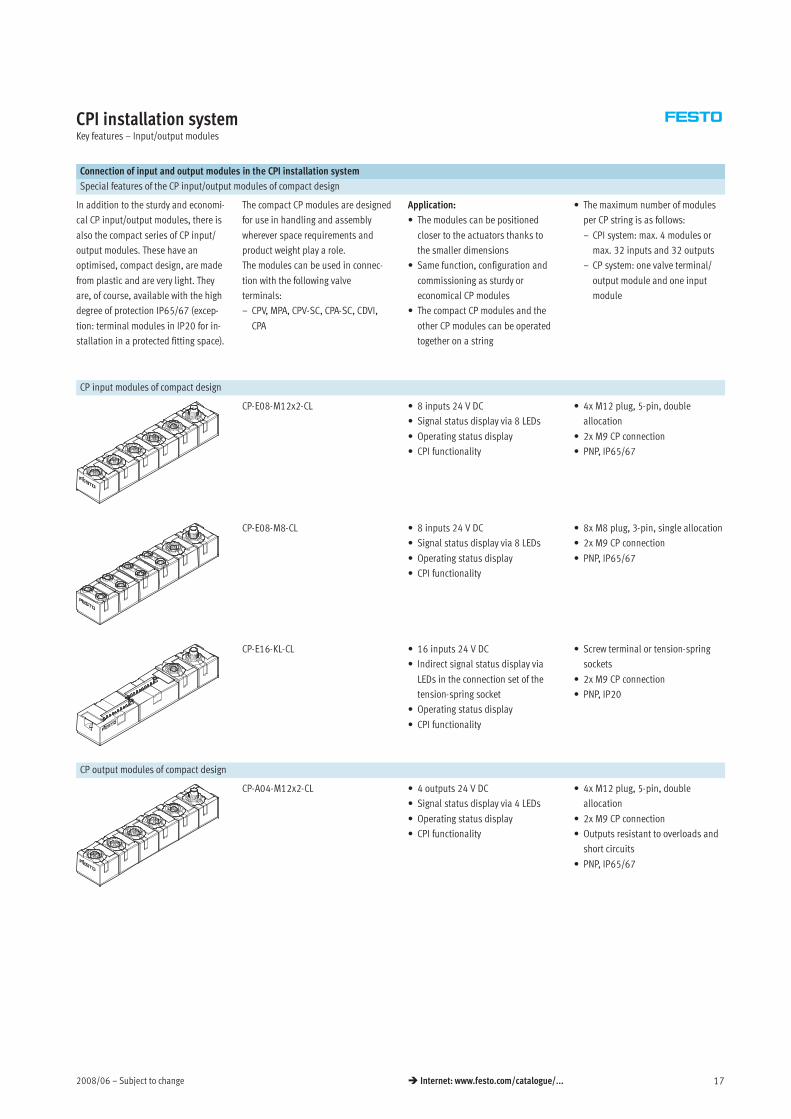
Special features of the CP input/output modules of compact design
In addition to the sturdy and economi-
cal CP input/output modules, there is
also the compact series of CP input/
output modules. These have an
optimised, compact design, are made
from plastic and are very light. They
are, of course, available with the high
degree of protection IP65/67 (excep-
tion: terminal modules in IP20 for in-
stallation in a protected fitting space).
The compact CP modules are designed
for use in handling and assembly
wherever space requirements and
product weight play a role.
The modules can be used in connec-
tion with the following valve
terminals:
– CPV, MPA, CPV-SC, CPA-SC, CDVI,
CPA
Application:
• The modules can be positioned
closer to the actuators thanks to
the smaller dimensions
• Same function, configuration and
commissioning as sturdy or
economical CP modules
• The compact CP modules and the
other CP modules can be operated
together on a string
• The maximum number of modules
per CP string is as follows:
– CPI system: max. 4 modules or
max. 32 inputs and 32 outputs
– CP system: one valve terminal/
output module and one input
module
CP input modules of compact design
In
Out
1
3
5
7
CP-E08-M12x2-CL • 8 inputs 24 V DC
• Signal status display via 8 LEDs
• Operating status display
• CPI functionality
• 4x M12 plug, 5-pin, double
allocation
• 2x M9 CP connection
• PNP, IP65/67
In
Out
1
3
5
7
0
2
4
6
CP-E08-M8-CL • 8 inputs 24 V DC
• Signal status display via 8 LEDs
• Operating status display
• CPI functionality
• 8x M8 plug, 3-pin, single allocation
• 2x M9 CP connection
• PNP, IP65/67
CP-E16-KL-CL • 16 inputs 24 V DC
• Indirect signal status display via
LEDs in the connection set of the
tension-spring socket
• Operating status display
• CPI functionality
• Screw terminal or tension-spring
sockets
• 2x M9 CP connection
• PNP, IP20
CP output modules of compact design
CP-A04-M12x2-CL • 4 outputs 24 V DC
• Signal status display via 4 LEDs
• Operating status display
• CPI functionality
• 4x M12 plug, 5-pin, double
allocation
• 2x M9 CP connection
• Outputs resistant to overloads and
short circuits
• PNP, IP65/67
Subject to change – 2008/0618 Internet: www.festo.com/catalogue/...
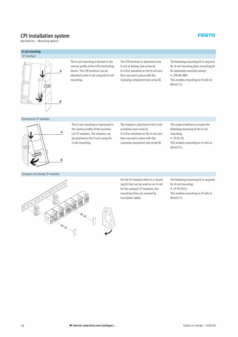
CPI installation systemKey features – Mounting options
H-rail mounting
CP interface
A
B
The H-rail mounting is formed in the
reverse profile of the CPX interlinking
blocks. The CPX terminal can be
attached to the H-rail using the H-rail
mounting.
The CPX terminal is attached to the
H-rail as follows (see arrow A).
It is first swivelled on the H-rail and
then secured in place with the
clamping component (see arrow B).
The following mounting kit is required
for H-rail mounting (plus mounting kit
for optionally mounted valves):
• CPA-BG-NRH
This enables mounting on H-rails to
EN 60715.
Economical CP modules
A
B
The H-rail mounting is impressed in
the reverse profile of the economi-
cal CP modules. The modules can
be attached to the H-rail using the
H-rail mounting.
The module is attached to the H-rail
as follows (see arrow A).
It is first swivelled on the H-rail and
then secured in place with the
clamping component (see arrow B).
The scope of delivery includes the
following mounting kit for H-rail
mounting:
• CP-EL-HS
This enables mounting on H-rails to
EN 60715.
Compact and sturdy CP modules
For the CP modules there is a mount-
ing kit that can be used on an H-rail.
On the compact CP modules, the
mounting holes are covered by
inscription labels.
The following mounting kit is required
for H-rail mounting:
• CP-TS-HS35
This enables mounting on H-rails to
EN 60715.
2008/06 – Subject to change 19 Internet: www.festo.com/catalogue/...
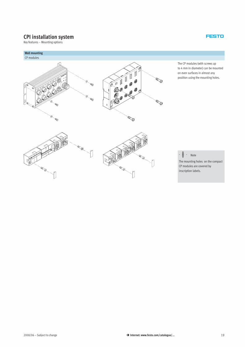
CPI installation systemKey features – Mounting options
Wall mounting
CP modules
The CP modules (with screws up
to 4 mm in diameter) can be mounted
on even surfaces in almost any
position using the mounting holes.
-H- Note
The mounting holes on the compact
CP modules are covered by
inscription labels.
Subject to change – 2008/0620 Internet: www.festo.com/catalogue/...
CPI installation systemKey features – Inscription system
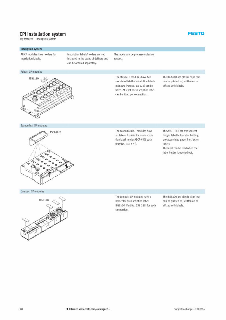
Inscription system
All CP modules have holders for
inscription labels.
Inscription labels/holders are not
included in the scope of delivery and
can be ordered separately.
The labels can be pre-assembled on
request.
Robust CP modules
IBS6x10 The sturdy CP modules have two
slots in which the inscription labels
IBS6x10 (Part No. 18 576) can be
fitted. At least one inscription label
can be fitted per connection.
The IBS6x10 are plastic clips that
can be printed on, written on or
affixed with labels.
Economical CP modules
ASCF-H-E2 The economical CP modules have
six lateral fixtures for one inscrip-
tion label holder ASCF-H-E2 each
(Part No. 547 473).
The ASCF-H-E2 are transparent
hinged label holders for holding
pre-assembled paper inscription
labels.
The label can be read when the
label holder is opened out.
Compact CP modules
IBS8x20The compact CP modules have a
holder for an inscription label
IBS8x20 (Part No. 539 388) for each
connection.
The IBS8x20 are plastic clips that
can be printed on, written on or
affixed with labels.
2008/06 – Subject to change 21 Internet: www.festo.com/catalogue/...
CPI installation systemKey features – Power supply
Operating voltage and load current supply
The following functions are made
available to the connected modules
through the CP cable:
• Connection for data exchange
• Operating voltage for internal
electronics
• Load current supply for the
connected inputs/sensors and/or
outputs/actuators
CP-E…Z or output modules from the
sturdy and the economical series have
a separate load voltage supply:
• Less load on the CP interface and CP
cable
• 0.5 A per output (max. 4 A supply
per output module)
• 1 A per 8 inputs
• Separate disconnection of the
consuming devices possible
Every module in the CPI system is
protected separately against overload
with electronic fuses.
The input modules without additional
supply provide a maximum sensor
supply of 500 mA in the sturdy design,
800 mA in the compact design and
700 mA in the economical design with
16 inputs and 1400 mA with 32 in-
puts.
The input modules with additional
supply provide up to 2 A residual
current for the connected sensors.
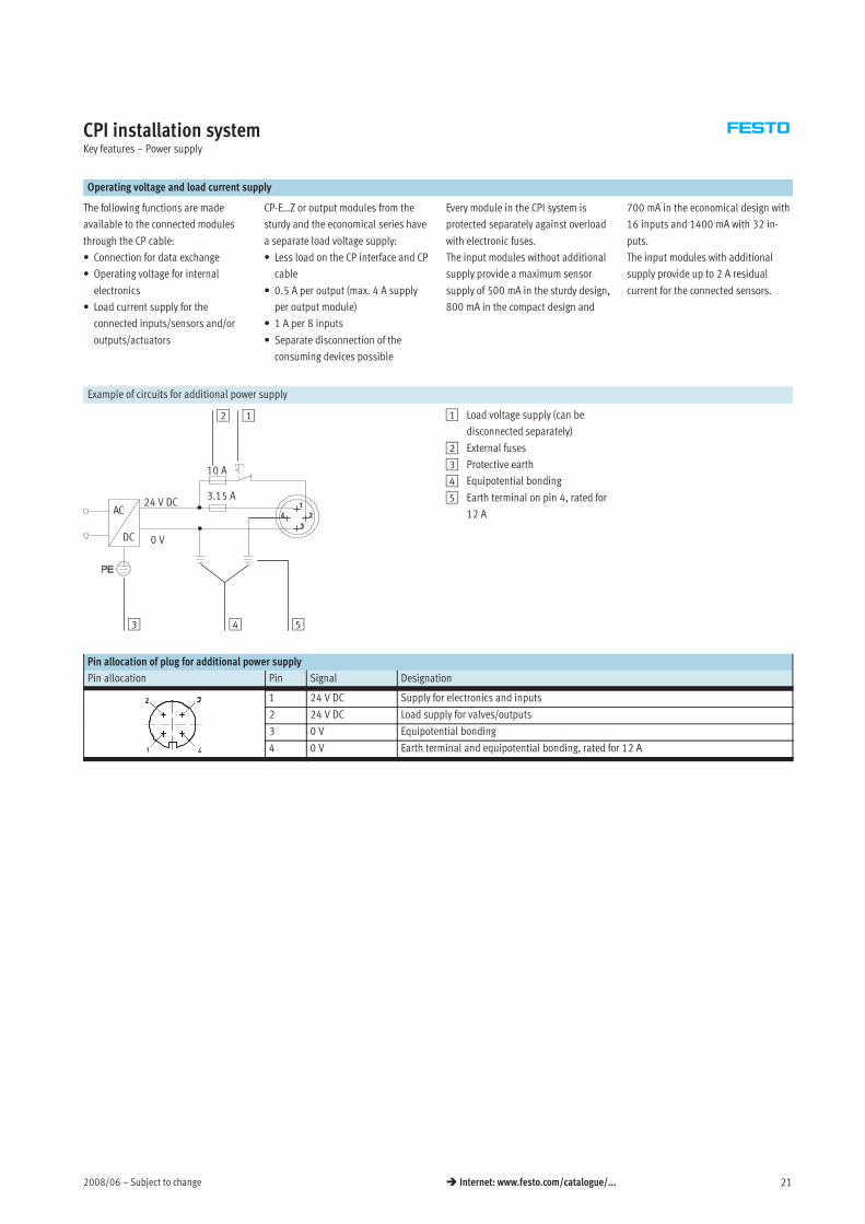
Example of circuits for additional power supply
DC
24 V DC
5
1
3 4
AC
10 A
0 V
3.15 A
2 1 Load voltage supply (can be
disconnected separately)
2 External fuses
3 Protective earth
4 Equipotential bonding
5 Earth terminal on pin 4, rated for
12 A
Pin allocation of plug for additional power supply
Pin allocation Pin Signal Designation
1 24 V DC Supply for electronics and inputs
2 24 V DC Load supply for valves/outputs
3 0 V Equipotential bonding
4 0 V Earth terminal and equipotential bonding, rated for 12 A
Subject to change – 2008/0622 Internet: www.festo.com/catalogue/...
CPI installation systemKey features – Power supply
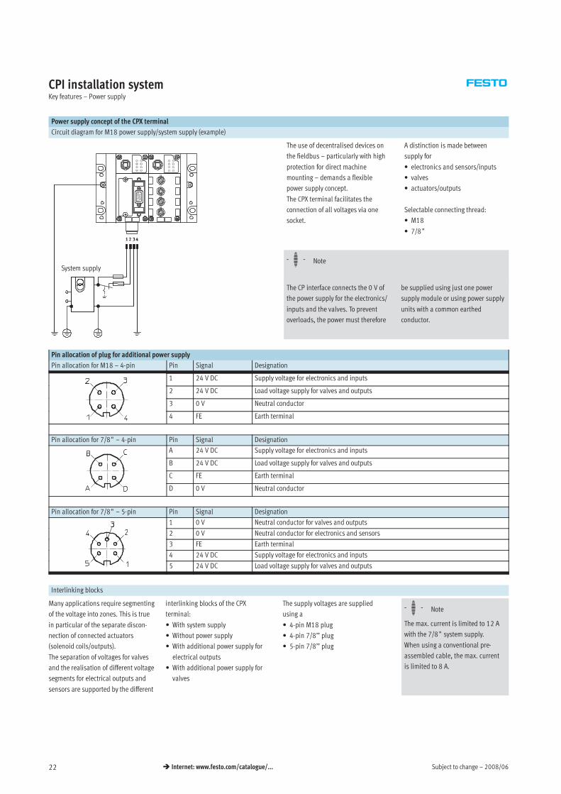
Power supply concept of the CPX terminal
Circuit diagram for M18 power supply/system supply (example)
The use of decentralised devices on
the fieldbus – particularly with high
protection for direct machine
mounting – demands a flexible
power supply concept.
The CPX terminal facilitates the
connection of all voltages via one
socket.
A distinction is made between
supply for
• electronics and sensors/inputs
• valves
• actuators/outputs
Selectable connecting thread:
• M18
• 7/8†
System supply-H- Note
The CP interface connects the 0 V of
the power supply for the electronics/
inputs and the valves. To prevent
overloads, the power must therefore
be supplied using just one power
supply module or using power supply
units with a common earthed
conductor.
Pin allocation of plug for additional power supply
Pin allocation for M18 – 4-pin Pin Signal Designation
1 24 V DC Supply voltage for electronics and inputs
2 24 V DC Load voltage supply for valves and outputs
3 0 V Neutral conductor
4 FE Earth terminal
Pin allocation for 7/8† – 4-pin Pin Signal Designation
A 24 V DC Supply voltage for electronics and inputs
B 24 V DC Load voltage supply for valves and outputs
C FE Earth terminal
D 0 V Neutral conductor
Pin allocation for 7/8† – 5-pin Pin Signal Designation
1 0 V Neutral conductor for valves and outputs
2 0 V Neutral conductor for electronics and sensors
3 FE Earth terminal
4 24 V DC Supply voltage for electronics and inputs
5 24 V DC Load voltage supply for valves and outputs
Interlinking blocks
Many applications require segmenting
of the voltage into zones. This is true
in particular of the separate discon-
nection of connected actuators
(solenoid coils/outputs).
The separation of voltages for valves
and the realisation of different voltage
segments for electrical outputs and
sensors are supported by the different
interlinking blocks of the CPX
terminal:
• With system supply
• Without power supply
• With additional power supply for
electrical outputs
• With additional power supply for
valves
The supply voltages are supplied
using a
• 4-pin M18 plug
• 4-pin 7/8’’ plug
• 5-pin 7/8’’ plug
-H- Note
The max. current is limited to 12 A
with the 7/8† system supply.
When using a conventional pre-
assembled cable, the max. current
is limited to 8 A.
2008/06 – Subject to change 23 Internet: www.festo.com/catalogue/...
CPI installation systemKey features – Diagnostics
General limits
System supply CP interface
The system supply provides the inter-
nal voltage for the entire CPX system
with
• max. 16 A for electronics and
sensors/inputs
• max. 16 A for actuators/outputs
and valves
The CP interface and the CP modules
connected to the CP interface get their
operating voltage from the connection
for electronics and sensors/inputs.
The operating voltage for the sensors/
actuators connected to the CP mod-
ules is supplied from the voltage for
valves. The CP interface supplies the
connected CP modules with
The CP interface supplies the
connected CP modules with
• max. 1.6 A per CP string
Diagnostics
General information Diagnostics via LED Diagnostics via control program/CPX-MMI
A comprehensive diagnostic function
is available for each string.
The diagnostic information can either
be detected via the LEDs on the mod-
ule and then read out and evaluated
via the controller software (non-field-
bus-specific) or displayed directly on
the CPX terminal via the CPX-MMI and
then evaluated and edited.
• Error in bus communication
• POWER, power supply display for
internal electronics
• POWER V, load voltage display for
valves
• 0 … 3, CP string allocation changed
or interrupted
There are also bus-specific LED
displays.
• Configuration error
• Bus error
• Operating voltage failure
• Falling below voltage tolerance
(valves)
• Short circuit in sensor voltage
supply
• Operating voltage failure at the
output modules
• Short circuit/overload at the output
modules
• Connection to one or more CP mod-
ules interrupted (valve terminal,
input/output modules)
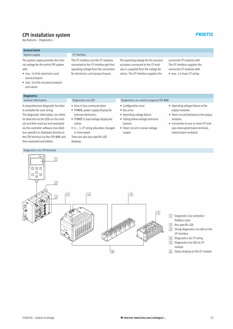
Diagnostics via CPX terminal
1
3
6
4
5
44
2
1 Diagnostics via controller/
fieldbus node
2 Bus-specific LED
3 String diagnostics via LED on the
CP interface
4 Diagnostics via CP string
5 Diagnostics via LED on CP
module
6 Status display on the CP module
Subject to change – 2008/0624 Internet: www.festo.com/catalogue/...
CPI installation systemKey features – CP interface
Diagnostics
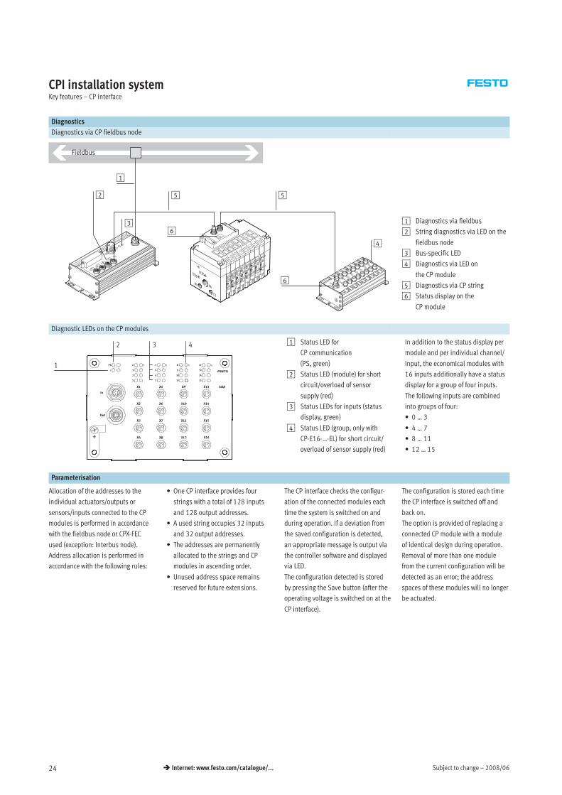
Diagnostics via CP fieldbus node
Fieldbus
1
2
3
5
4
6
5
61 Diagnostics via fieldbus
2 String diagnostics via LED on the
fieldbus node
3 Bus-specific LED
4 Diagnostics via LED on
the CP module
5 Diagnostics via CP string
6 Status display on the
CP module
Diagnostic LEDs on the CP modules
1
2 3 4 1 Status LED for
CP communication
(PS, green)
2 Status LED (module) for short
circuit/overload of sensor
supply (red)
3 Status LEDs for inputs (status
display, green)
4 Status LED (group, only with
CP-E16-…-EL) for short circuit/
overload of sensor supply (red)
In addition to the status display per
module and per individual channel/
input, the economical modules with
16 inputs additionally have a status
display for a group of four inputs.
The following inputs are combined
into groups of four:
• 0 … 3
• 4 … 7
• 8 … 11
• 12 … 15
Parameterisation
Allocation of the addresses to the
individual actuators/outputs or
sensors/inputs connected to the CP
modules is performed in accordance
with the fieldbus node or CPX-FEC
used (exception: Interbus node).
Address allocation is performed in
accordance with the following rules:
• One CP interface provides four
strings with a total of 128 inputs
and 128 output addresses.
• A used string occupies 32 inputs
and 32 output addresses.
• The addresses are permanently
allocated to the strings and CP
modules in ascending order.
• Unused address space remains
reserved for future extensions.
The CP interface checks the configur-
ation of the connected modules each
time the system is switched on and
during operation. If a deviation from
the saved configuration is detected,
an appropriate message is output via
the controller software and displayed
via LED.
The configuration detected is stored
by pressing the Save button (after the
operating voltage is switched on at the
CP interface).
The configuration is stored each time
the CP interface is switched off and
back on.
The option is provided of replacing a
connected CP module with a module
of identical design during operation.
Removal of more than one module
from the current configuration will be
detected as an error; the address
spaces of these modules will no longer
be actuated.
2008/06 – Subject to change 25 Internet: www.festo.com/catalogue/...
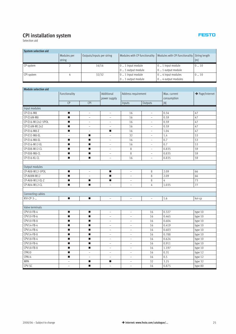
CPI installation systemSelection aid
System selection aid
Modules per
string
Outputs/inputs per string Modules with CP functionality Modules with CPI functionality String length
[m]
CP system 2 16/16 0 … 1 input module
0 … 1 output module
0 … 1 input module
0 … 1 output module
0 … 10
CPI system 4 32/32 0 … 1 input module
0 … 1 output module
0 … 4 input modules
0 … 4 output modules
0 … 10
Module selection aid
Functionality Additional
power supply
Address requirement Max. current
consumption
Page/Internet
CP CPI
p pp y
Inputs Outputs [A]
Input modules
CP-E16-M8 – – 16 – 0.54 47
CP-E16N-M8 – – 16 – 0.59 47
CP-E16-M12x2-5POL – – 16 – 0.59 47
CP-E16N-M12x2 – – 16 – 0.59 47
CP-E16-M8-Z – 16 – 1.04 47
CP-E32-M8-EL – – 32 – 1.4 53
CP-E16-M8-EL – 16 – 0.7 53
CP-E16-M12-EL – 16 – 0.7 53
CP-E08-M12-CL – 8 – 0.835 59
CP-E08-M8-CL – 8 – 0.835 59
CP-E16-KL-CL – 16 – 0.835 59
Output modules
CP-A08-M12-5POL – – 8 2.09 66
CP-A08N-M12 – – 8 2.09 66
CP-A08-M12-EL-Z – 8 4 73
CP-A04-M12-CL – – 4 1.035 77
Connecting cables
KVI-CP-3-… – – – 1.6 kvi-cp
Valve terminals
CPV10-FB-4 – – 16 0.327 type 10
CPV10-FB-6 – – 16 0.465 type 10
CPV10-FB-8 – – 16 0.604 type 10
CPV14-FB-4 – – 16 0.419 type 10
CPV14-FB-6 – – 16 0.603 type 10
CPV14-FB-8 – – 16 0.788 type 10
CPV18-FB-4 – – 16 0.624 type 10
CPV18-FB-6 – – 16 0.911 type 10
CPV18-FB-8 – – 16 1.197 type 10
CPA10 – – – 16 0.31 type 12
CPA14 – – – 16 0.5 type 12
MPA – – 32 3.25 type 32
CPV-SC – – – 16 0.875 type 80
Subject to change – 2008/0626 Internet: www.festo.com/catalogue/...
CPI installation systemSelection aid
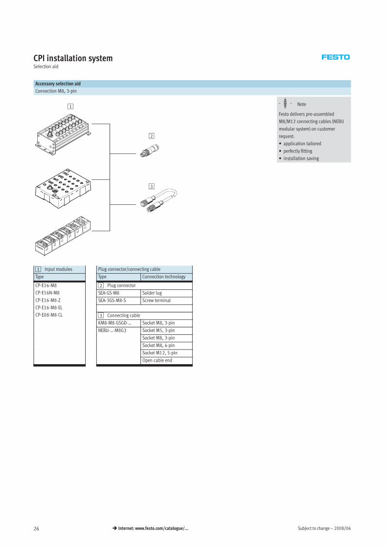
Accessory selection aid
Connection M8, 3-pin
1
2
-H- Note
Festo delivers pre-assembled
M8/M12 connecting cables (NEBU
modular system) on customer
request:
• application tailored
• perfectly fitting
• installation saving
3
In
Out
1
3
5
7
0
2
4
6
1 Input modules Plug connector/connecting cable
Type Type Connection technology
CP-E16-M8 2 Plug connector
CP-E16N-M8 SEA-GS-M8 Solder lug
CP-E16-M8-Z SEA-3GS-M8-S Screw terminal
CP-E16-M8-EL
CP-E08-M8-CL 3 Connecting cable
KM8-M8-GSGD-… Socket M8, 3-pin
NEBU-…-M8G3 Socket M5, 3-pin3
Socket M8, 3-pin
Socket M8, 4-pin
Socket M12, 5-pin
Open cable end
2008/06 – Subject to change 27 Internet: www.festo.com/catalogue/...
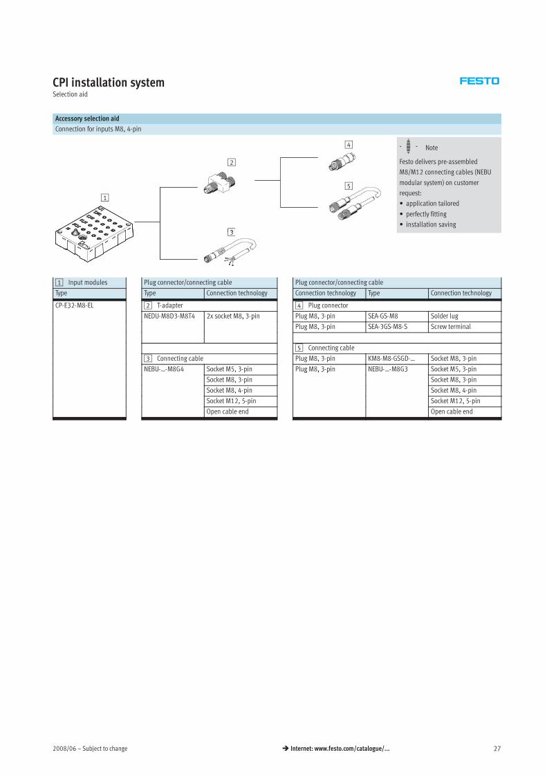
CPI installation systemSelection aid
Accessory selection aid
Connection for inputs M8, 4-pin
1
2
3
4
5
-H- Note
Festo delivers pre-assembled
M8/M12 connecting cables (NEBU
modular system) on customer
request:
• application tailored
• perfectly fitting
• installation saving3
1 Input modules Plug connector/connecting cable Plug connector/connecting cable
Type Type Connection technology Connection technology Type Connection technology
CP-E32-M8-EL 2 T-adapter 4 Plug connector3
NEDU-M8D3-M8T4 2x socket M8, 3-pin Plug M8, 3-pin SEA-GS-M8 Solder lug3 , 3 p
Plug M8, 3-pin SEA-3GS-M8-S Screw terminal
5 Connecting cable
3 Connecting cable Plug M8, 3-pin KM8-M8-GSGD-… Socket M8, 3-pin
NEBU-…-M8G4 Socket M5, 3-pin Plug M8, 3-pin NEBU-…-M8G3 Socket M5, 3-pin
Socket M8, 3-pin
g , 3 p 3
Socket M8, 3-pin
Socket M8, 4-pin Socket M8, 4-pin
Socket M12, 5-pin Socket M12, 5-pin
Open cable end Open cable end
Subject to change – 2008/0628 Internet: www.festo.com/catalogue/...
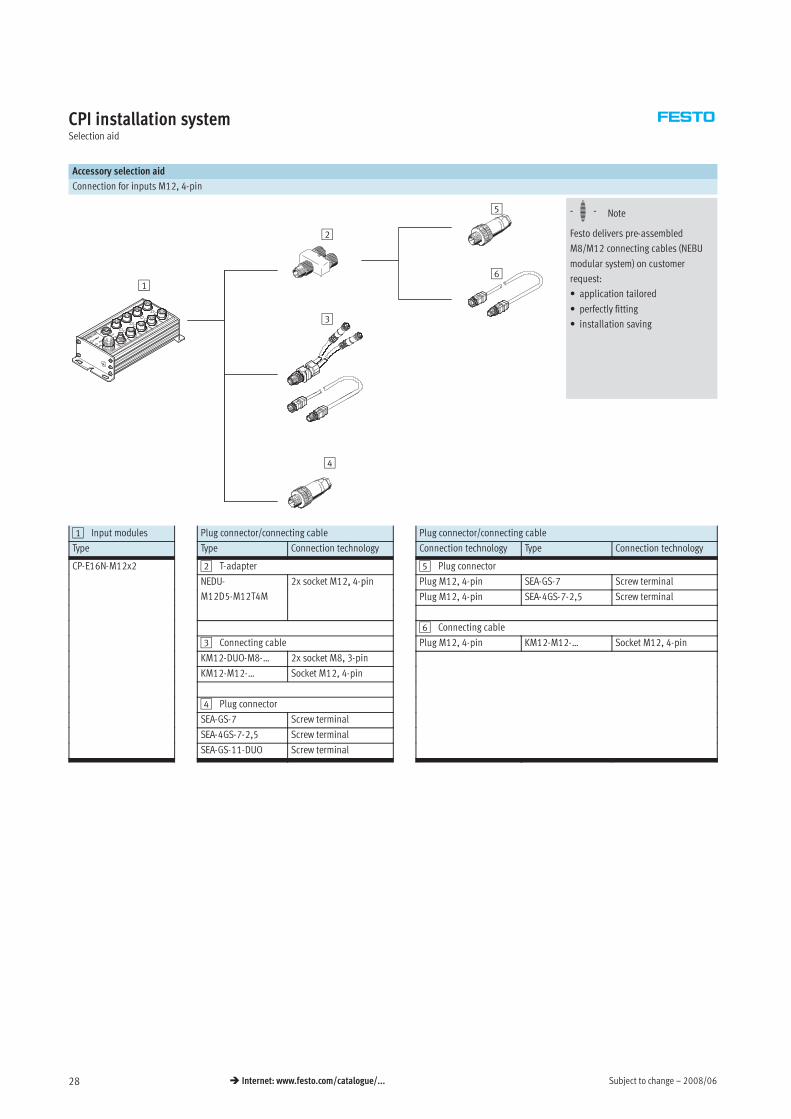
CPI installation systemSelection aid
Accessory selection aid
Connection for inputs M12, 4-pin
1
2
3
5
6
-H- Note
Festo delivers pre-assembled
M8/M12 connecting cables (NEBU
modular system) on customer
request:
• application tailored
• perfectly fitting
• installation saving
4
1 Input modules Plug connector/connecting cable Plug connector/connecting cable
Type Type Connection technology Connection technology Type Connection technology
CP-E16N-M12x2 2 T-adapter 5 Plug connector
NEDU- 2x socket M12, 4-pin Plug M12, 4-pin SEA-GS-7 Screw terminal
M12D5-M12T4M
, p
Plug M12, 4-pin SEA-4GS-7-2,5 Screw terminal
6 Connecting cable
3 Connecting cable Plug M12, 4-pin KM12-M12-… Socket M12, 4-pin
KM12-DUO-M8-… 2x socket M8, 3-pin
KM12-M12-… Socket M12, 4-pin
4 Plug connector
SEA-GS-7 Screw terminal
SEA-4GS-7-2,5 Screw terminal
SEA-GS-11-DUO Screw terminal
2008/06 – Subject to change 29 Internet: www.festo.com/catalogue/...
CPI installation systemSelection aid
Accessory selection aid
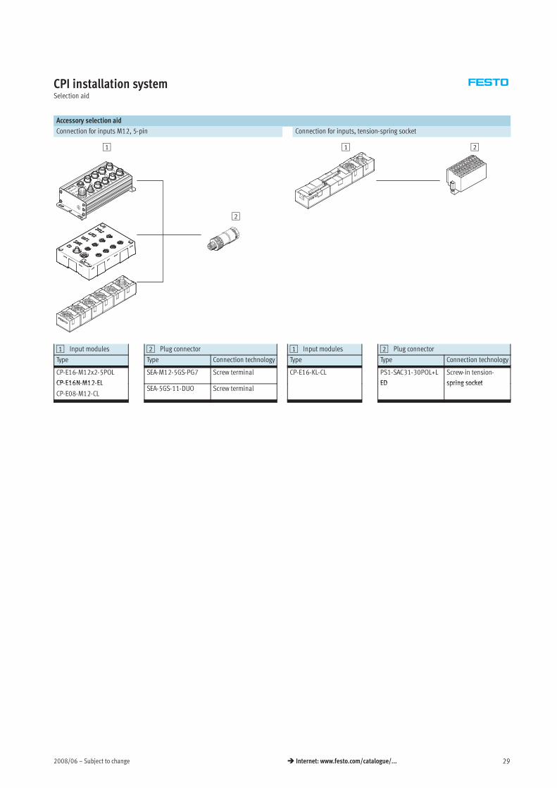
Connection for inputs M12, 5-pin Connection for inputs, tension-spring socket
1
2
In
Out
1
3
5
7
1 2
1 Input modules 2 Plug connector 1 Input modules 2 Plug connector
Type Type Connection technology Type Type Connection technology
CP-E16-M12x2-5POL
CP-E16N-M12-EL
SEA-M12-5GS-PG7 Screw terminal CP-E16-KL-CL PS1-SAC31-30POL+L
ED
Screw-in tension-
spring socketCP-E16N-M12-EL
CP-E08-M12-CLSEA-5GS-11-DUO Screw terminal
ED spring socket
Subject to change – 2008/0630 Internet: www.festo.com/catalogue/...
CPI installation systemSelection aid
Accessory selection aid
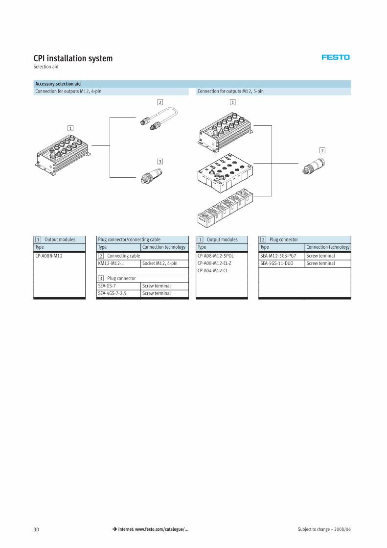
Connection for outputs M12, 4-pin Connection for outputs M12, 5-pin
1
2
3
1
2
1 Output modules Plug connector/connecting cable 1 Output modules 2 Plug connector
Type Type Connection technology Type Type Connection technology
CP-A08N-M12 2 Connecting cable CP-A08-M12-5POL SEA-M12-5GS-PG7 Screw terminal
KM12-M12-… Socket M12, 4-pin
5
CP-A08-M12-EL-Z SEA-5GS-11-DUO Screw terminal
CP-A04-M12-CL
3 Plug connector
SEA-GS-7 Screw terminal
SEA-4GS-7-2,5 Screw terminal
2008/09 – Subject to change 31 Internet: www.festo.com/catalogue/...
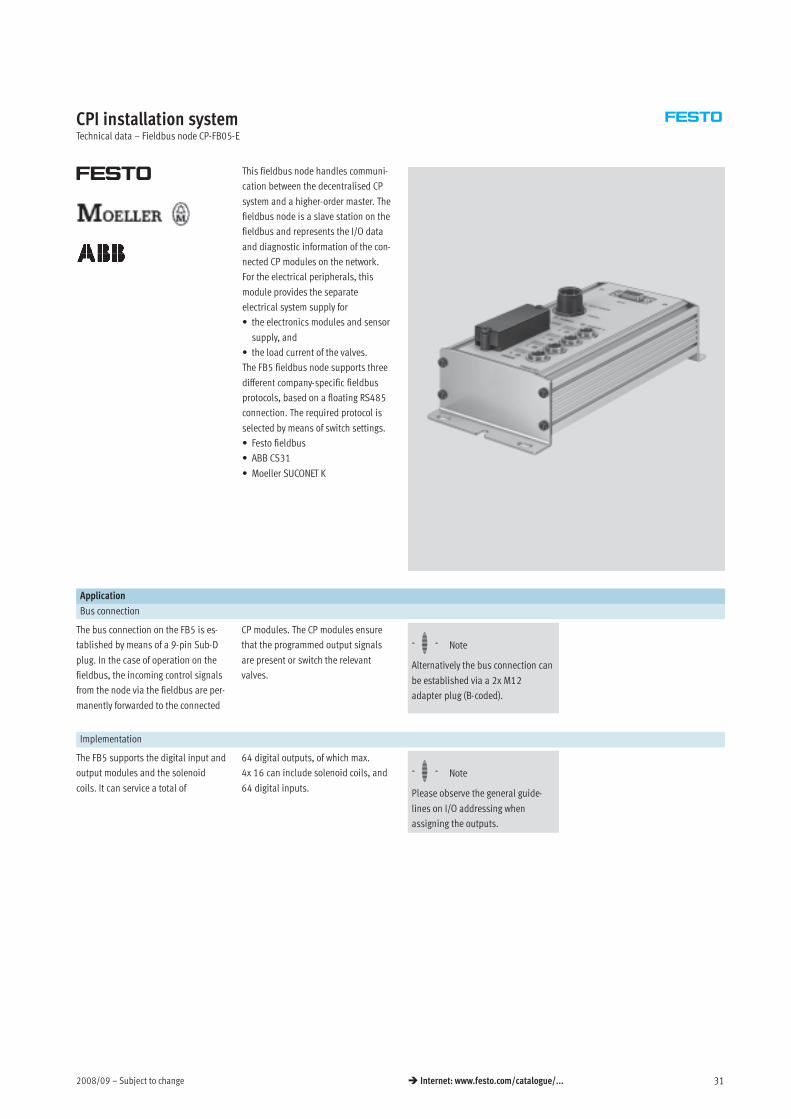
CPI installation systemTechnical data – Fieldbus node CP-FB05-E
This fieldbus node handles communi-
cation between the decentralised CP
system and a higher-order master. The
fieldbus node is a slave station on the
fieldbus and represents the I/O data
and diagnostic information of the con-
nected CP modules on the network.
For the electrical peripherals, this
module provides the separate
electrical system supply for
• the electronics modules and sensor
supply, and
• the load current of the valves.
The FB5 fieldbus node supports three
different company-specific fieldbus
protocols, based on a floating RS485
connection. The required protocol is
selected by means of switch settings.
• Festo fieldbus
• ABB CS31
• Moeller SUCONET K
Application
Bus connection
The bus connection on the FB5 is es-
tablished by means of a 9-pin Sub-D
plug. In the case of operation on the
fieldbus, the incoming control signals
from the node via the fieldbus are per-
manently forwarded to the connected
CP modules. The CP modules ensure
that the programmed output signals
are present or switch the relevant
valves.
-H- Note
Alternatively the bus connection can
be established via a 2x M12
adapter plug (B-coded).
Implementation
The FB5 supports the digital input and
output modules and the solenoid
coils. It can service a total of
64 digital outputs, of which max.
4x 16 can include solenoid coils, and
64 digital inputs.
-H- Note
Please observe the general guide-
lines on I/O addressing when
assigning the outputs.
Subject to change – 2008/0932 Internet: www.festo.com/catalogue/...
CPI installation systemTechnical data – Fieldbus node CP-FB05-E
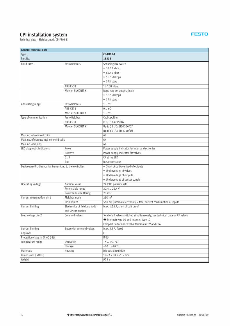
General technical data
Type CP-FB05-E
Part No. 18238
Baud rates Festo fieldbus Set using HW switch
• 31.25 kbps
• 62.50 kbps
• 187.50 kbps
• 375 kbps
ABB CS31 187.50 kbps
Moeller SUCONET K Baud rate set automatically
• 187.50 kbps
• 375 kbps
Addressing range Festo fieldbus 1 … 98g g
ABB CS31 0 … 60
Moeller SUCONET K 1 … 98
Type of communication Festo fieldbus Cyclic pollingyp
ABB CS31 I16, O16 or I/O16
Moeller SUCONET K Up to 32 I/O: SIS-K-06/07
Up to 64 I/O: SIS-K-10/10
Max. no. of solenoid coils 64
Max. no. of outputs incl. solenoid coils 64
Max. no. of inputs 64
LED diagnostic indicators Power Power supply indicator for internal electronicsg
Power V Power supply indicator for valves
0…3 CP string LED
Bus Bus error status
Device-specific diagnostics transmitted to the controller • Short circuit/overload of outputs
• Undervoltage of valves
• Undervoltage of outputs
• Undervoltage of sensor supply
Operating voltage Nominal value 24 V DC polarity-safep g g
Permissible range 20.4 … 26.4 V
Power failure buffering 20 ms
Current consumption pin 1 Fieldbus node 250 mAp p
CP modules 560 mA (internal electronics) + total current consumption of inputs
Current limiting Electronics of fieldbus node
and CP connection
Max. 1.25 A, short circuit proof
Load voltage pin 2 Solenoid valves Total of all valves switched simultaneously, see technical data on CP valves
Internet: type 10 and Internet: type 12
Compact Performance valve terminals CPV and CPA
Current limiting Supply for solenoid valves Max. 2.5 A, fused
Approval CE
Protection class to EN 60 529 IP65
Temperature range Operation –5 … +50 °Cp g
Storage –20 … +70 °C
Materials Housing Die-cast aluminium
Dimensions (LxWxD) 196.4 x 88 x 61.5 mm
Weight 925 g
2008/09 – Subject to change 33 Internet: www.festo.com/catalogue/...
CPI installation systemTechnical data – Fieldbus node CP-FB05-E
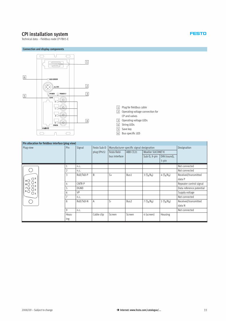
Connection and display components
4
3
2
1
5
6
1 Plug for fieldbus cable
2 Operating voltage connection for
CP and valves
3 Operating voltage LEDs
4 String LEDs
5 Save key
6 Bus-specific LED
Pin allocation for fieldbus interface (plug view)
Plug view Pin Signal Festo Sub-D Manufacturer-specific signal designation Designation
plug (IP65) Festo field- ABB CS31 Moeller SUCONET K
bus interface
3
Sub-D, 9-pin DIN (round),
5-pin
1 n.c. Not connected
2 n.c. Not connected
3 RxD/TxD-P B S+ Bus1 3 (TA/RA) 4 (TA/RA) Received/transmitted
data P
4 CNTR-P Repeater control signal
5 DGND Data reference potential
6 VP Supply voltage
7 n.c. Not connected
8 RxD/TxD-N A S- Bus2 7 (TB/RB) 1 (TB/RB) Received/transmitted
data N
9 n.c. Not connected
Hous-
ing
Cable clip Screen Screen 4 (screen) Housing
Subject to change – 2008/0934 Internet: www.festo.com/catalogue/...
CPI installation systemAccessories – Fieldbus node CP-FB05-E
Ordering data
Designation Type Part No.
Power supply
Power supply socket, straight M18x1, 4-pin for 1.5 mm2 NTSD-GD-9 18493
for 2.5 mm2 NTSD-GD-13,5 18526
Power supply socket, angled M18x1, 4-pin for 1.5 mm2 NTSD-WD-9 18527
for 2.5 mm2 NTSD-WD-11 533119
Fieldbus connection
Fieldbus socket, Sub-D connection FBS-Sub-9-GS-DP-B 532216
M12 adapter FBA-2-M12-5POL-RK 533118
Valve terminal connection
Connecting cable WS-WD 0,25 m KVI-CP-3-WS-WD-0,25 540327g
0,5 m KVI-CP-3-WS-WD-0,5 540328
2 m KVI-CP-3-WS-WD-2 540329
5 m KVI-CP-3-WS-WD-5 540330
8 m KVI-CP-3-WS-WD-8 540331
Connecting cable GS-GD 2 m KVI-CP-3-GS-GD-2 540332g
5 m KVI-CP-3-GS-GD-5 540333
8 m KVI-CP-3-GS-GD-8 540334
Mounting
Mounting for H-rail CP-TS-HS35 170169
User documentation
User documentation – Bus node CP-FB5-E German P.BE-CP-FB5-E-DE 1651055
English P.BE-CP-FB5-E-EN 165205
French P.BE-CP-FB5-E-FR 165135
Italian P.BE-CP-FB5-E-IT 165165
2008/09 – Subject to change 35 Internet: www.festo.com/catalogue/...
CPI installation systemTechnical data – Fieldbus node CP-FB06-E
This fieldbus node handles communi-
cation between the decentralised CP
system and a higher-order master. The
fieldbus node is a slave station on the
fieldbus and represents the I/O data
and diagnostic information of the con-
nected CP modules on the network.
For the electrical peripherals, this
module provides the separate
electrical system supply for
• the electronics modules and sensor
supply, and
• the load current of the valves.
Application
Bus connection
The bus connection is established via
two 9-pin M23 connections with a
typical Interbus pin allocation.
The plug and socket are labelled with
Remote IN and Remote OUT in
accordance with the definition for the
Interbus remote bus. Both bus cables
are always routed to the fieldbus node
and looped through in accordance
with the ring structure of the Interbus.
The CP fieldbus node receives the data
from the higher-order controller and
forwards it to the connected CP valve
terminals or electrical output
modules. The signal status of the
inputs is requested from the input
modules and forwarded to the CP
fieldbus nodes.
Implementation
The FB6 supports the digital input and
output modules and the solenoid
coils. It can service a total of
64 digital outputs, of which max.
64 can include solenoid coils, and
64 digital inputs.
-H- Note
Please observe the general guide-
lines regarding addressing when
assigning outputs.
Subject to change – 2008/0936 Internet: www.festo.com/catalogue/...
CPI installation systemTechnical data – Fieldbus node CP-FB06-E
General technical data
Type CP-FB06-E
Part No. 18225
Baud rates 500 kbps
ID code 3
No. of process data bits 16, 32, 48 or 64 depending on expansion
PCP channel No
Configuration support Icon file for CMD software
Station description file with CMD software
Max. no. of solenoid coils 64
Max. no. of outputs incl. solenoid coils 64
Max. no. of inputs 64
LED diagnostic indicators Power Power supply indicator for internal electronicsg
Power V Power supply indicator for valves
0…3 CP string LED
RC Remotebus check
BA Bus active
RD Remotebus disable
Device-specific diagnostics transmitted to the controller as common
message (peripherals errors)
• Short circuit/overload of outputs
• Undervoltage of valves
• Undervoltage of outputs
• Undervoltage of sensor supply
Additional functions Test routine for checking the valves and outputs without bus communication
Operating voltage Nominal value 24 V DC polarity-safep g g
Permissible range 20.4 … 26.4 V
Power failure buffering 20 ms
Current consumption pin 1 Fieldbus node 250 mAp p
CP modules 560 mA (internal electronics) + total current consumption of inputs
Current limiting Electronics of fieldbus node
and CP connection
Max. 1.25 A, short circuit proof
Load voltage pin 2 Solenoid valves Total of all valves switched simultaneously, see technical data on CP valves
Internet: type 10 and Internet: type 12
(Compact Performance valve terminals CPV and CPA)
Current limiting Supply for solenoid valves Max. 2.5 A, fused
Protection class to EN 60 529 IP65
Temperature range Operation –5 … +50 °Cp g
Storage –20 … +70 °C
Materials Housing Die-cast aluminium
Dimensions (LxWxD) 196.4 x 88 x 61.5 mm
Weight 915 g
2008/09 – Subject to change 37 Internet: www.festo.com/catalogue/...
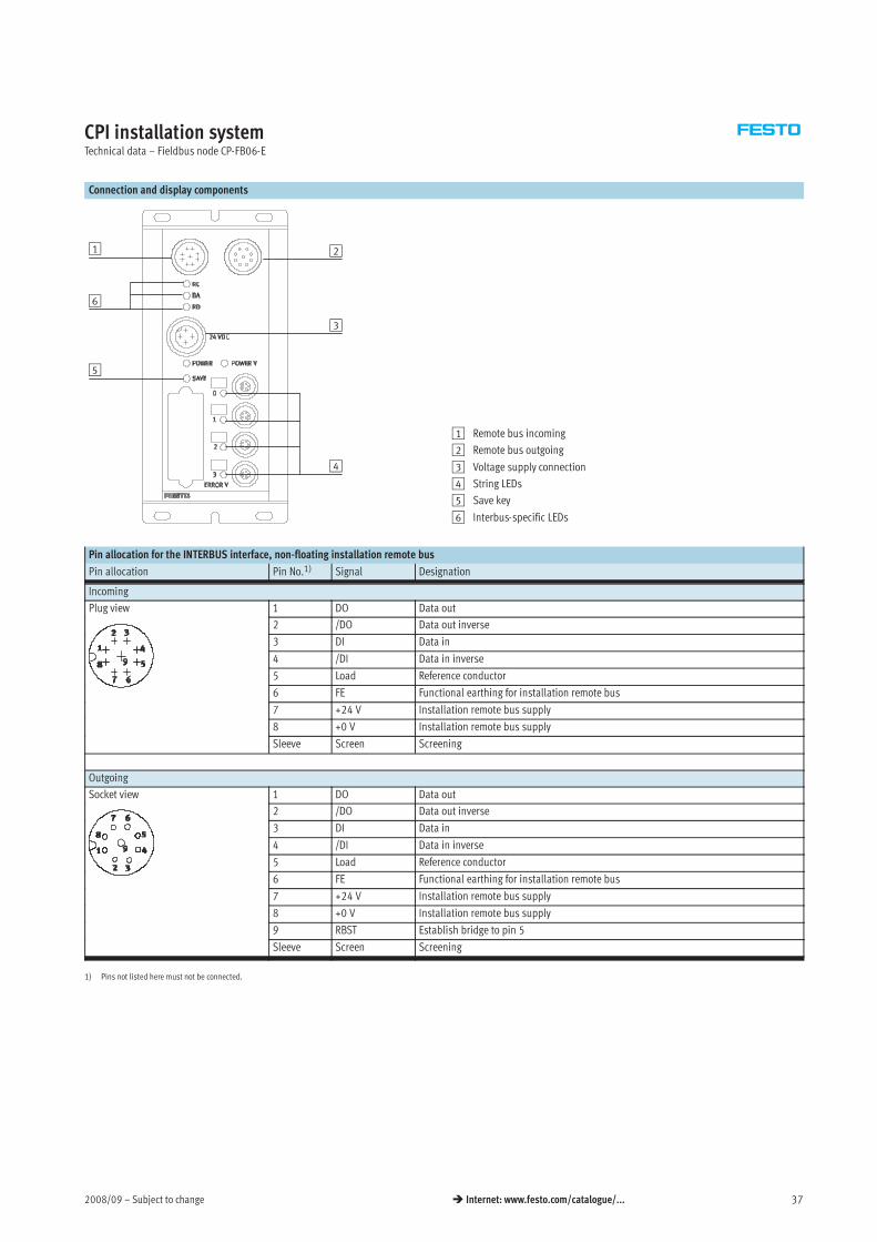
CPI installation systemTechnical data – Fieldbus node CP-FB06-E
Connection and display components
1 2
3
6
5
4
1 Remote bus incoming
2 Remote bus outgoing
3 Voltage supply connection
4 String LEDs
5 Save key
6 Interbus-specific LEDs
Pin allocation for the INTERBUS interface, non-floating installation remote bus
Pin allocation Pin No.1) Signal Designation
Incoming
Plug view 1 DO Data out
2 /DO Data out inverse
3 DI Data in
4 /DI Data in inverse
5 Load Reference conductor
6 FE Functional earthing for installation remote bus
7 +24 V Installation remote bus supply
8 +0 V Installation remote bus supply
Sleeve Screen Screening
Outgoing
Socket view 1 DO Data out
2 /DO Data out inverse
3 DI Data in
4 /DI Data in inverse
5 Load Reference conductor
6 FE Functional earthing for installation remote bus
7 +24 V Installation remote bus supply
8 +0 V Installation remote bus supply
9 RBST Establish bridge to pin 5
Sleeve Screen Screening
1) Pins not listed here must not be connected.
Subject to change – 2008/0938 Internet: www.festo.com/catalogue/...
CPI installation systemAccessories – Fieldbus node CP-FB06-E
Ordering data
Designation Type Part No.
Power supply
Power supply socket, straight M18x1, 4-pin for 1.5 mm2 NTSD-GD-9 18493
for 2.5 mm2 NTSD-GD-13,5 18526
Power supply socket, angled M18x1, 4-pin for 1.5 mm2 NTSD-WD-9 18527
for 2.5 mm2 NTSD-WD-11 533119
Valve terminal connection
Connecting cable WS-WD 0,25 m KVI-CP-3-WS-WD-0,25 540327g
0,5 m KVI-CP-3-WS-WD-0,5 540328
2 m KVI-CP-3-WS-WD-2 540329
5 m KVI-CP-3-WS-WD-5 540330
8 m KVI-CP-3-WS-WD-8 540331
Connecting cable GS-GD 2 m KVI-CP-3-GS-GD-2 540332g
5 m KVI-CP-3-GS-GD-5 540333
8 m KVI-CP-3-GS-GD-8 540334
Mounting
Mounting for H-rail CP-TS-HS35 170169
User documentation
User documentation – Bus node CP-FB06-E German P.BE-CP-FB6-E-DE 165106
English P.BE-CP-FB6-E-EN 165206
French P.BE-CP-FB6-E-FR 165136
Italian P.BE-CP-FB6-E-IT 165166
Spanish P.BE-CP-FB6-E-ES 165236
Swedish P.BE-CP-FB6-E-SV 165266
2008/09 – Subject to change 39 Internet: www.festo.com/catalogue/...
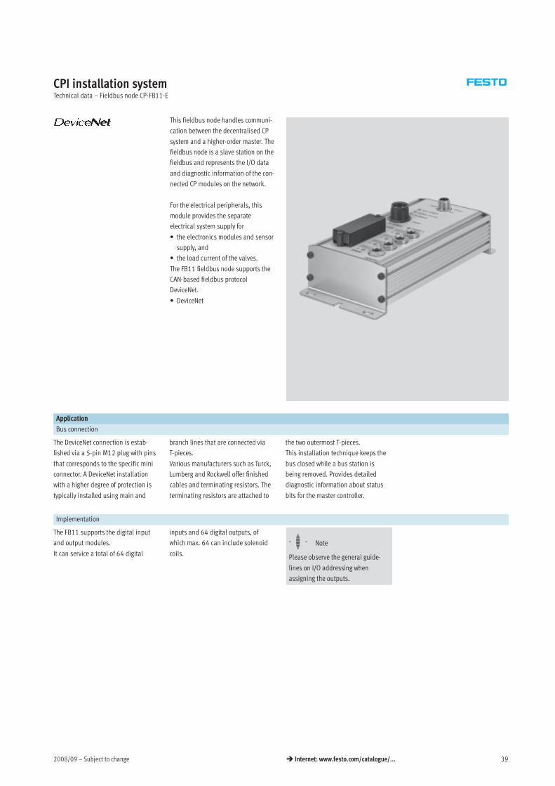
CPI installation systemTechnical data – Fieldbus node CP-FB11-E
This fieldbus node handles communi-
cation between the decentralised CP
system and a higher-order master. The
fieldbus node is a slave station on the
fieldbus and represents the I/O data
and diagnostic information of the con-
nected CP modules on the network.
For the electrical peripherals, this
module provides the separate
electrical system supply for
• the electronics modules and sensor
supply, and
• the load current of the valves.
The FB11 fieldbus node supports the
CAN-based fieldbus protocol
DeviceNet.
• DeviceNet
Application
Bus connection
The DeviceNet connection is estab-
lished via a 5-pin M12 plug with pins
that corresponds to the specific mini
connector. A DeviceNet installation
with a higher degree of protection is
typically installed using main and
branch lines that are connected via
T-pieces.
Various manufacturers such as Turck,
Lumberg and Rockwell offer finished
cables and terminating resistors. The
terminating resistors are attached to
the two outermost T-pieces.
This installation technique keeps the
bus closed while a bus station is
being removed. Provides detailed
diagnostic information about status
bits for the master controller.
Implementation
The FB11 supports the digital input
and output modules.
It can service a total of 64 digital
inputs and 64 digital outputs, of
which max. 64 can include solenoid
coils.
-H- Note
Please observe the general guide-
lines on I/O addressing when
assigning the outputs.
Subject to change – 2008/0940 Internet: www.festo.com/catalogue/...
CPI installation systemTechnical data – Fieldbus node CP-FB11-E
General technical data
Type CP-FB11-E
Part No. 18 227
Baud rates Set using HW switch
• 125 kbps
• 250 kbps
• 500 kbps
Addressing range Set using 2 rotary switches
0 … 63
Product type Communication converter (12 dec.)
Product code 2282 hex./35050 dec.
Type of communication Polling/Cos/Bit Strobe
Configuration support EDS file and graphics symbol
Max. no. of solenoid coils 64
Max. no. of outputs and solenoid coils 64
Max. no. of inputs 64
LED diagnostic indicators Bus/Power Operating voltage of busg
Module status Operating status
I/O Error Internal error
Device-specific diagnosis via DeviceNet • Short circuit/overload of outputs
• Undervoltage of valves
• Undervoltage of outputs
• Undervoltage of sensor supply
• Interrupt point on CP string
Operating voltage Nominal value 24 V DC polarity-safep g g
Permissible range 20.4 … 26.4 V
Power failure buffering 20 ms
Current consumption pin 1 Fieldbus node 250 mAp p
CP module 560 mA (internal electronics) + total current consumption of inputs, internal
Current limiting Electronics of fieldbus node
and CP connection
Max. 1.25 A, short circuit proof
Current consumption pin 2 Solenoid valves Total of all valves switched simultaneously, see technical data on CP valves
Internet: type 10 and Internet: type 12
(Compact Performance valve terminals CPV and CPA)
Protection class to EN 60 529 IP65
Temperature range Operation –5 … +50 °Cp g
Storage/transport –20 … +70 °C
Materials Housing Die-cast aluminium
Dimensions (HxWxD) 196.4 x 88 x 61.5 mm
Grid dimension 72 mm
Weight 950 g
2008/09 – Subject to change 41 Internet: www.festo.com/catalogue/...
CPI installation systemTechnical data – Fieldbus node CP-FB11-E
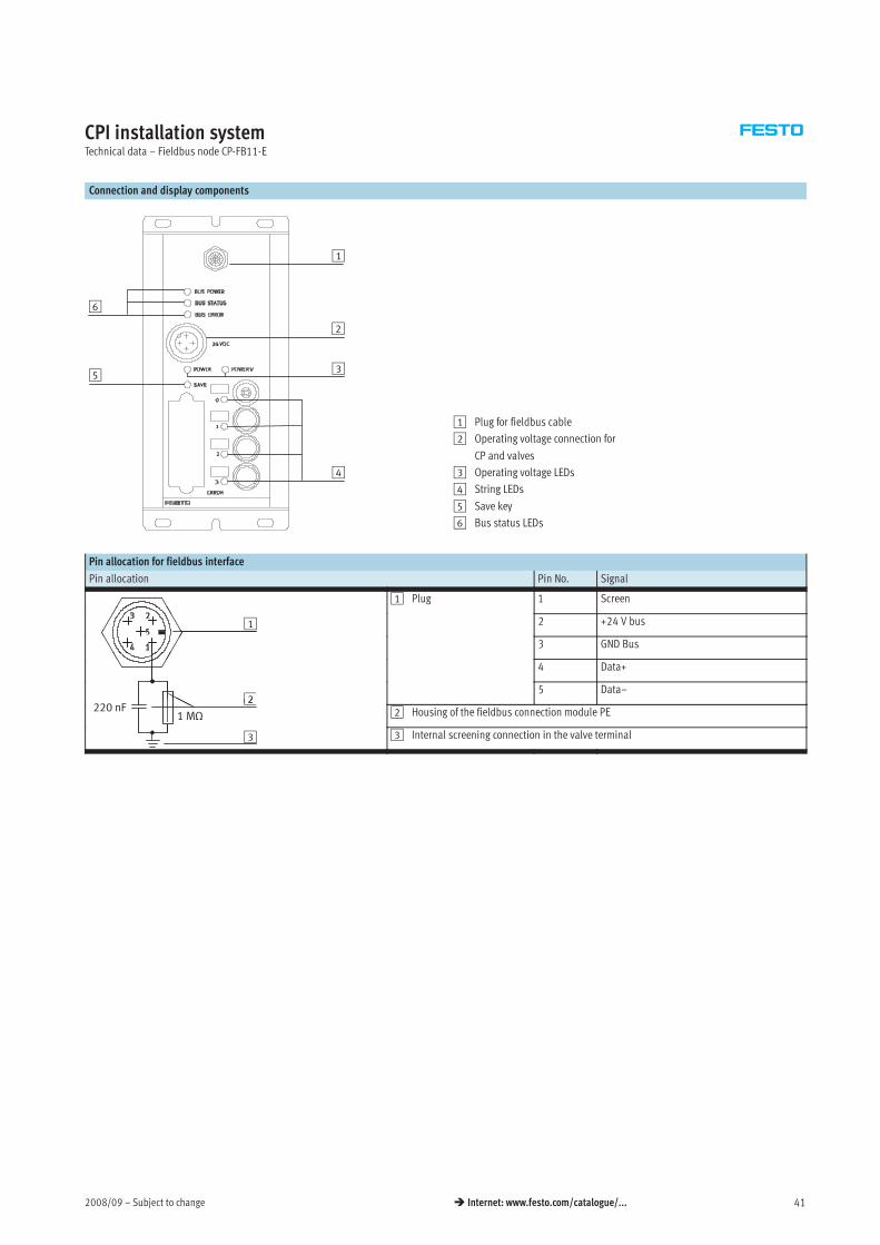
Connection and display components
4
1
2
6
53
1 Plug for fieldbus cable
2 Operating voltage connection for
CP and valves
3 Operating voltage LEDs
4 String LEDs
5 Save key
6 Bus status LEDs
Pin allocation for fieldbus interface
Pin allocation Pin No. Signal
1 Plug 1 Screen
1 2 +24 V bus
3 GND Bus
4 Data+
2220 F
5 Data–2
1 MΩ220 nF 2 Housing of the fieldbus connection module PE
3 3 Internal screening connection in the valve terminal
Subject to change – 2008/0942 Internet: www.festo.com/catalogue/...
CPI installation systemAccessories – Fieldbus node CP-FB11-E
Ordering data
Designation Type Part No.
Power supply
Power supply socket, straight M18x1, 4-pin for 1.5 mm2 NTSD-GD-9 18493
for 2.5 mm2 NTSD-GD-13,5 18526
Power supply socket, angled M18x1, 4-pin for 1.5 mm2 NTSD-WD-9 18527
for 2.5 mm2 NTSD-WD-11 533119
Fieldbus connection
Bus connection, straight, PG9, 5-pin FBSD-GD-9-5POL 18324
Valve terminal connection
Connecting cable WS-WD 0,25 m KVI-CP-3-WS-WD-0,25 540327g
0,5 m KVI-CP-3-WS-WD-0,5 540328
2 m KVI-CP-3-WS-WD-2 540329
5 m KVI-CP-3-WS-WD-5 540330
8 m KVI-CP-3-WS-WD-8 540331
Connecting cable GS-GD 2 m KVI-CP-3-GS-GD-2 540332g
5 m KVI-CP-3-GS-GD-5 540333
8 m KVI-CP-3-GS-GD-8 540334
Mounting
Mounting, for H-rail CP-TS-HS35 170169
User documentation
User documentation – Bus node CP-FB11-E German P.BE-CP-FB11-E-DE 165111
English P.BE-CP-FB11-E-EN 165211
French P.BE-CP-FB11-E-FR 165141
Italian P.BE-CP-FB11-E-IT 165171
Spanish P.BE-CP-FB11-E-ES 165241
Swedish P.BE-CP-FB11-E-SV 165271
2008/09 – Subject to change 43 Internet: www.festo.com/catalogue/...
CPI installation systemTechnical data – Fieldbus node CP-FB13-E
This fieldbus node handles communi-
cation between the decentralised CP
system and a higher-order master via
Profibus DP. The fieldbus node is a
slave station on the fieldbus and
represents the I/O data and diagnos-
tic information of the connected CP
modules on the network.
For the electrical peripherals, this
module provides the separate
electrical system supply for
• the electronics modules and sensor
supply, and
• the load current of the valves.
The status of the voltage supplies and
the bus communication is indicated
via the LEDs Power, Power Valves,
String Error and Bus Error.
• Profibus-DP
Application
Bus connection
The bus connection is established via
a 9-pin Sub-D socket with a typical
Profibus allocation (to EN 50 170).
The bus connector plug (with protec-
tion class IP65 from Festo or IP20
from other manufacturers) facilitates
the connection of an incoming and an
outgoing bus cable. An active bus
terminal can be connected using the
integrated DIL switch. The Sub-D
interface is designed for the control of
network components via a fibre optic
cable connection and provides
detailed diagnostic information for
master detection.
-H- Note
Alternatively the bus connection can
be established via a 2x M12
adapter plug (B-coded).
Implementation
The FB13 supports digital input and
output modules and solenoid coils.
64 digital outputs in total, of which
max. 64 solenoid coils.
Max. 64 digital inputs for recording
sensor signals.
-H- Note
When assigning the electrical
modules, please observe the
configuration guidelines for valve
terminals in relation to address
allocation and the number of
occupied module positions.
Subject to change – 2008/0944 Internet: www.festo.com/catalogue/...
CPI installation systemTechnical data – Fieldbus node CP-FB13-E
General technical data
Type CP-FB13-E
Part No. 174337
Baud rates Automatic detection
9.6 kBaud … 12 MBaud
Addressing range Set using 2 DIL switches
1 … 125
Product family 4: Valves
Ident. number 0xFB13
Type of communication Cyclic communication
Configuration support GSD file and bitmaps
Max. no. of solenoid coils 64
Max. no. of outputs and solenoid coils 64
Max. no. of inputs 64
LED diagnostic indicators Power Operating voltage of electronicsg
Power V Operating voltage of valves and outputs
Bus Error Communication error
0…3 CP string
Device-specific diagnostics via Profibus-DP • Short circuit/overload of outputs
• Undervoltage of valves
• Undervoltage of outputs
• Undervoltage of sensor supply
• Interrupt points on CP string
Additional functions • Test routine for checking the valves and outputs without bus communication
Operating voltage Nominal value 24 V DC polarity-safep g g
Permissible range 20.4 … 26.4 V
Power failure buffering 20 ms
Current consumption pin 1 Fieldbus node 250 mAp p
CP module 560 mA (internal electronics) + total current consumption of inputs, internal
Current limiting Electronics of fieldbus node
and CP connection
Max. 1.25 A, short circuit proof
Current consumption pin 2 Solenoid valves Total of all valves switched simultaneously, see technical data on CP valves
Internet: type 10 and Internet: type 12
(Compact Performance valve terminals CPV and CPA)
Current limiting Supply for solenoid valves Max. 2.5 A, fused
Protection class to EN 60 529 IP65
Temperature range Operation –5 … +50 °Cp g
Storage/transport –20 … +70 °C
Materials Housing Die-cast aluminium
Dimensions (LxWxD) 196.4 x 88 x 61.5 mm
Grid dimension 72 mm
Weight 925 g
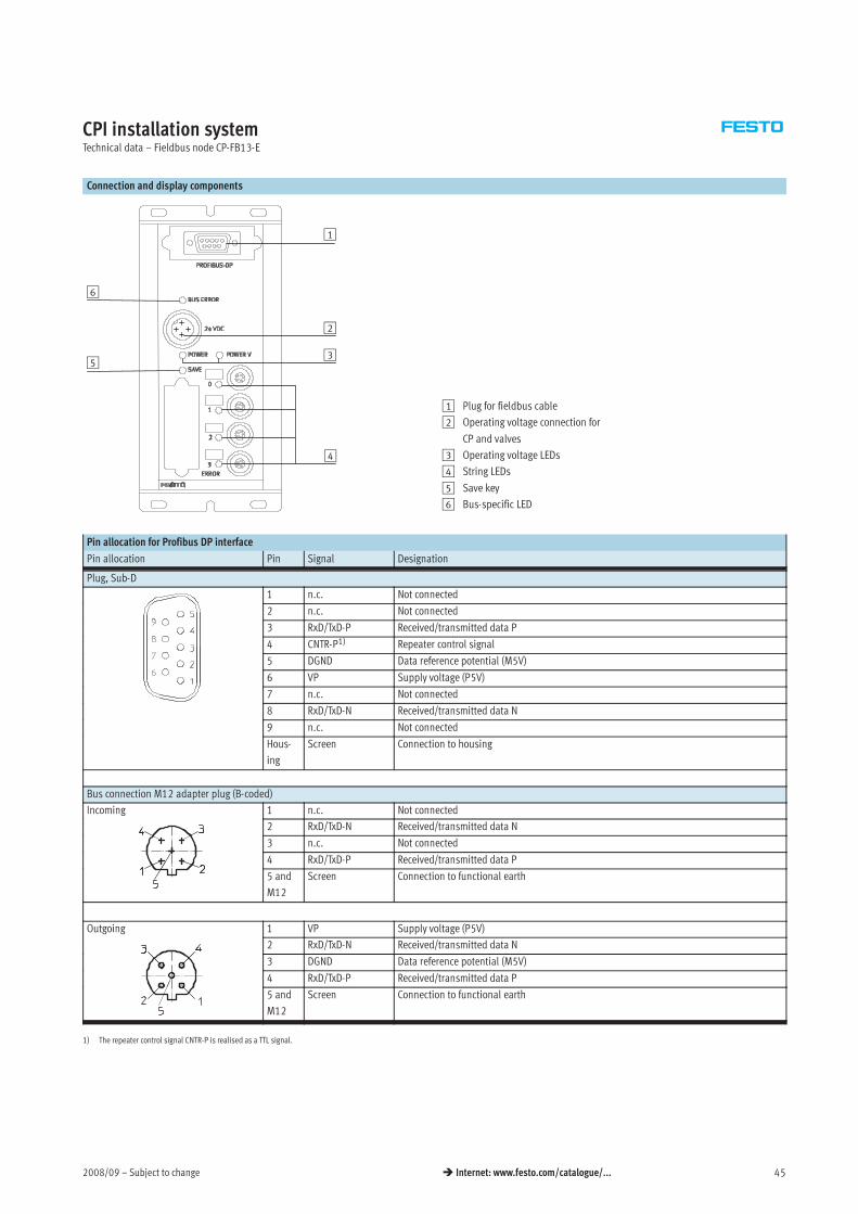
2008/09 – Subject to change 45 Internet: www.festo.com/catalogue/...
CPI installation systemTechnical data – Fieldbus node CP-FB13-E
Connection and display components
4
3
2
1
5
6
1 Plug for fieldbus cable
2 Operating voltage connection for
CP and valves
3 Operating voltage LEDs
4 String LEDs
5 Save key
6 Bus-specific LED
Pin allocation for Profibus DP interface
Pin allocation Pin Signal Designation
Plug, Sub-D
1 n.c. Not connected
2 n.c. Not connected
3 RxD/TxD-P Received/transmitted data P
4 CNTR-P1) Repeater control signal
5 DGND Data reference potential (M5V)
6 VP Supply voltage (P5V)
7 n.c. Not connected
8 RxD/TxD-N Received/transmitted data N
9 n.c. Not connected
Hous-
ing
Screen Connection to housing
Bus connection M12 adapter plug (B-coded)
Incoming 1 n.c. Not connected
2 RxD/TxD-N Received/transmitted data N
3 n.c. Not connected
4 RxD/TxD-P Received/transmitted data P
5 and
M12
Screen Connection to functional earth
Outgoing 1 VP Supply voltage (P5V)
2 RxD/TxD-N Received/transmitted data N
3 DGND Data reference potential (M5V)
4 RxD/TxD-P Received/transmitted data P
5 and
M12
Screen Connection to functional earth
1) The repeater control signal CNTR-P is realised as a TTL signal.
Subject to change – 2008/0946 Internet: www.festo.com/catalogue/...
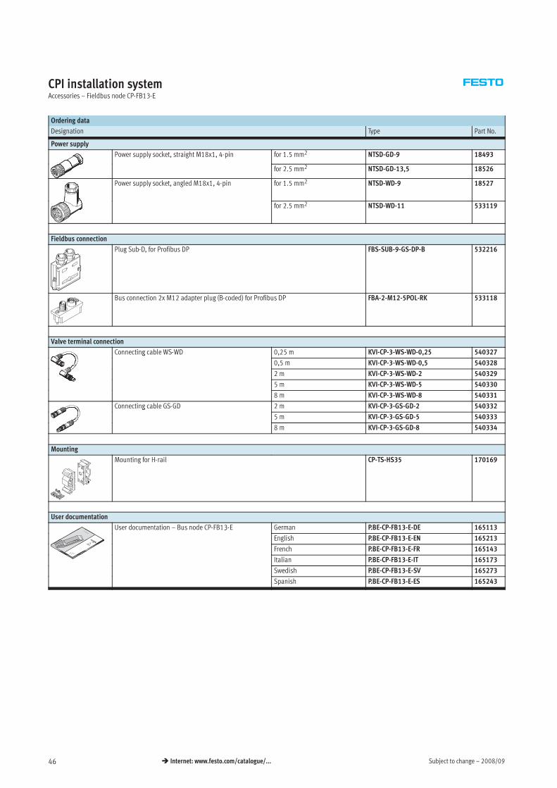
CPI installation systemAccessories – Fieldbus node CP-FB13-E
Ordering data
Designation Type Part No.
Power supply
Power supply socket, straight M18x1, 4-pin for 1.5 mm2 NTSD-GD-9 18493
for 2.5 mm2 NTSD-GD-13,5 18526
Power supply socket, angled M18x1, 4-pin for 1.5 mm2 NTSD-WD-9 18527
for 2.5 mm2 NTSD-WD-11 533119
Fieldbus connection
Plug Sub-D, for Profibus DP FBS-SUB-9-GS-DP-B 532216
Bus connection 2x M12 adapter plug (B-coded) for Profibus DP FBA-2-M12-5POL-RK 533118
Valve terminal connection
Connecting cable WS-WD 0,25 m KVI-CP-3-WS-WD-0,25 540327g
0,5 m KVI-CP-3-WS-WD-0,5 540328
2 m KVI-CP-3-WS-WD-2 540329
5 m KVI-CP-3-WS-WD-5 540330
8 m KVI-CP-3-WS-WD-8 540331
Connecting cable GS-GD 2 m KVI-CP-3-GS-GD-2 540332g
5 m KVI-CP-3-GS-GD-5 540333
8 m KVI-CP-3-GS-GD-8 540334
Mounting
Mounting for H-rail CP-TS-HS35 170169
User documentation
User documentation – Bus node CP-FB13-E German P.BE-CP-FB13-E-DE 1651133
English P.BE-CP-FB13-E-EN 165213
French P.BE-CP-FB13-E-FR 165143
Italian P.BE-CP-FB13-E-IT 165173
Swedish P.BE-CP-FB13-E-SV 165273
Spanish P.BE-CP-FB13-E-ES 165243
2008/09 – Subject to change 47 Internet: www.festo.com/catalogue/...
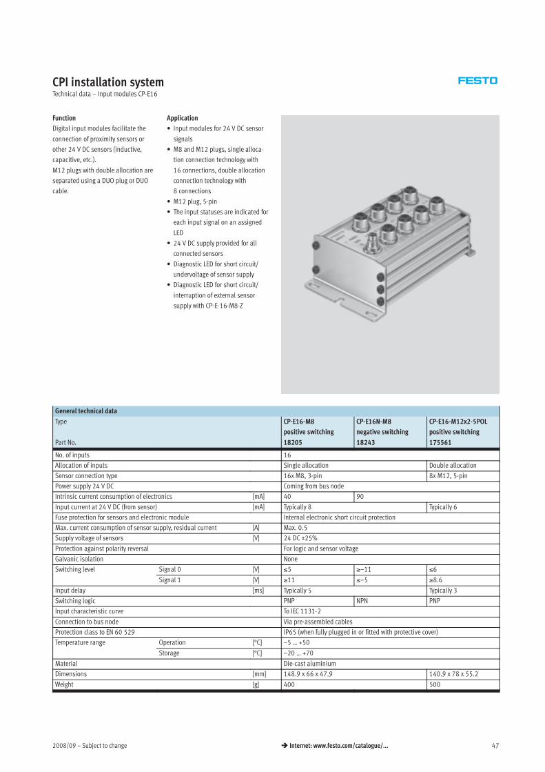
CPI installation systemTechnical data – Input modules CP-E16
Function
Digital input modules facilitate the
connection of proximity sensors or
other 24 V DC sensors (inductive,
capacitive, etc.).
M12 plugs with double allocation are
separated using a DUO plug or DUO
cable.
Application
• Input modules for 24 V DC sensor
signals
• M8 and M12 plugs, single alloca-
tion connection technology with
16 connections, double allocation
connection technology with
8 connections
• M12 plug, 5-pin
• The input statuses are indicated for
each input signal on an assigned
LED
• 24 V DC supply provided for all
connected sensors
• Diagnostic LED for short circuit/
undervoltage of sensor supply
• Diagnostic LED for short circuit/
interruption of external sensor
supply with CP-E-16-M8-Z
General technical data
Type CP-E16-M8
positive switching
CP-E16N-M8
negative switching
CP-E16-M12x2-5POL
positive switching
Part No. 18205 18243 175561
No. of inputs 16
Allocation of inputs Single allocation Double allocation
Sensor connection type 16x M8, 3-pin 8x M12, 5-pin
Power supply 24 V DC Coming from bus node
Intrinsic current consumption of electronics [mA] 40 90
Input current at 24 V DC (from sensor) [mA] Typically 8 Typically 6
Fuse protection for sensors and electronic module Internal electronic short circuit protection
Max. current consumption of sensor supply, residual current [A] Max. 0.5
Supply voltage of sensors [V] 24 DC ±25%
Protection against polarity reversal For logic and sensor voltage
Galvanic isolation None
Switching level Signal 0 [V] ≤5 ≥–11 ≤6g
Signal 1 [V] ≥11 ≤–5 ≥8.6
Input delay [ms] Typically 5 Typically 3
Switching logic PNP NPN PNP
Input characteristic curve To IEC 1131-2
Connection to bus node Via pre-assembled cables
Protection class to EN 60 529 IP65 (when fully plugged in or fitted with protective cover)
Temperature range Operation [°C] –5 … +50p g
Storage [°C] –20 … +70
Material Die-cast aluminium
Dimensions [mm] 148.9 x 66 x 47.9 140.9 x 78 x 55.2
Weight [g] 400 500
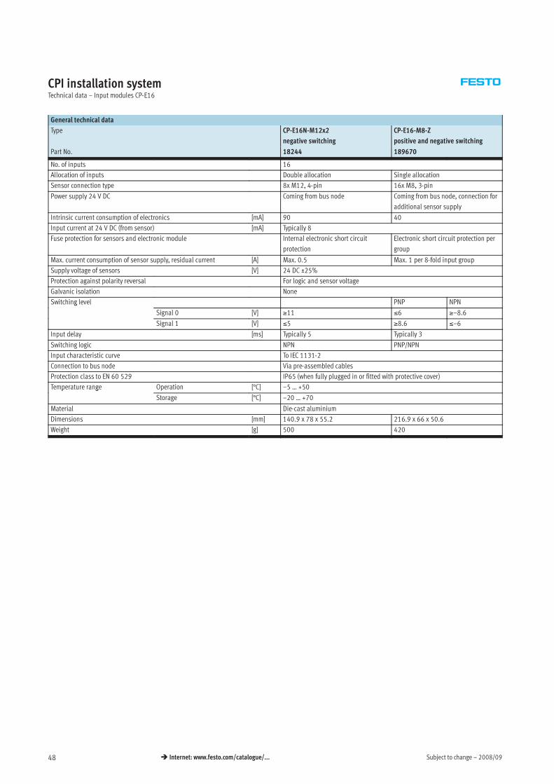
Subject to change – 2008/0948 Internet: www.festo.com/catalogue/...
CPI installation systemTechnical data – Input modules CP-E16
General technical data
Type CP-E16N-M12x2
negative switching
CP-E16-M8-Z
positive and negative switching
Part No. 18244 189670
No. of inputs 16
Allocation of inputs Double allocation Single allocation
Sensor connection type 8x M12, 4-pin 16x M8, 3-pin
Power supply 24 V DC Coming from bus node Coming from bus node, connection for
additional sensor supply
Intrinsic current consumption of electronics [mA] 90 40
Input current at 24 V DC (from sensor) [mA] Typically 8
Fuse protection for sensors and electronic module Internal electronic short circuit
protection
Electronic short circuit protection per
group
Max. current consumption of sensor supply, residual current [A] Max. 0.5 Max. 1 per 8-fold input group
Supply voltage of sensors [V] 24 DC ±25%
Protection against polarity reversal For logic and sensor voltage
Galvanic isolation None
Switching level PNP NPNg
Signal 0 [V] ≥11 ≤6 ≥–8.6
Signal 1 [V] ≤5 ≥8.6 ≤–6
Input delay [ms] Typically 5 Typically 3
Switching logic NPN PNP/NPN
Input characteristic curve To IEC 1131-2
Connection to bus node Via pre-assembled cables
Protection class to EN 60 529 IP65 (when fully plugged in or fitted with protective cover)
Temperature range Operation [°C] –5 … +50p g
Storage [°C] –20 … +70
Material Die-cast aluminium
Dimensions [mm] 140.9 x 78 x 55.2 216.9 x 66 x 50.6
Weight [g] 500 420
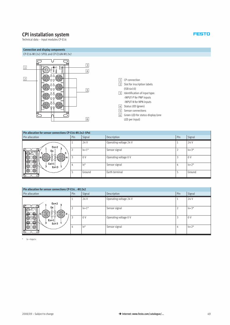
2008/09 – Subject to change 49 Internet: www.festo.com/catalogue/...
CPI installation systemTechnical data – Input modules CP-E16
Connection and display components
CP-E16-M12x2-5POL and CP-E16N-M12x2
5
1
6
4
3
2 1 CP connection
2 Slot for inscription labels
(ISB 6x10)
3 Identification of input type:
-INPUT-P for PNP inputs
-INPUT-N for NPN inputs
4 Status LED (green)
5 Sensor connections
6 Green LED for status display (one
LED per input)
Pin allocation for sensor connections CP-E16-M12x2-5Pol
Pin allocation Pin Signal Description Pin Signal
1 24 V Operating voltage 24 V 1 24 V
2 Ix+1* Sensor signal 2 Ix+3*
3 0 V Operating voltage 0 V 3 0 V
4 Ix* Sensor signal 4 Ix+2*
5 Ground Earth terminal 5 Ground
Pin allocation for sensor connections CP-E16…-M12x2
Pin allocation Pin Signal Description Pin Signal
1 24 V Operating voltage 24 V 1 24 V
2 Ix+1* Sensor signal 2 Ix+3*
3 0 V Operating voltage 0 V 3 0 V
4 Ix* Sensor signal 4 Ix+2*
* Ix = Input x
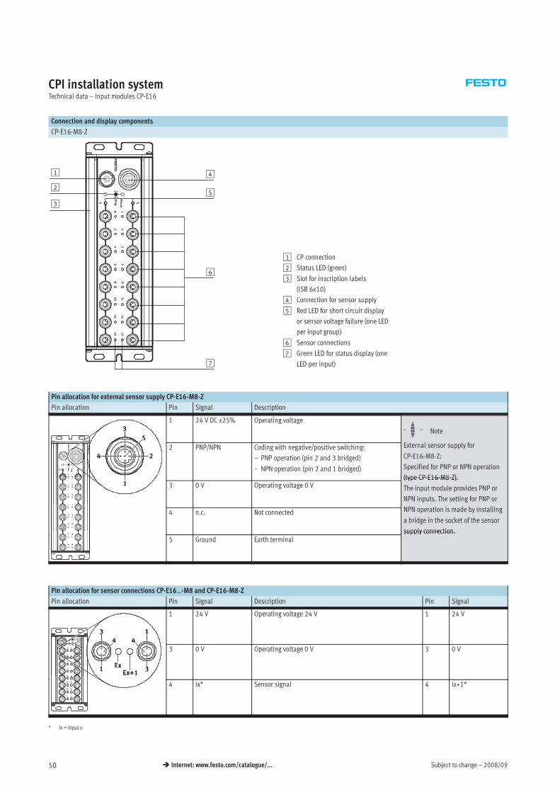
Subject to change – 2008/0950 Internet: www.festo.com/catalogue/...
CPI installation systemTechnical data – Input modules CP-E16
Connection and display components
CP-E16-M8-Z
1
3
4
6
7
52
1 CP connection
2 Status LED (green)
3 Slot for inscription labels
(ISB 6x10)
4 Connection for sensor supply
5 Red LED for short circuit display
or sensor voltage failure (one LED
per input group)
6 Sensor connections
7 Green LED for status display (one
LED per input)
Pin allocation for external sensor supply CP-E16-M8-Z
Pin allocation Pin Signal Description
1 24 V DC ±25% Operating voltage
-H- Note
2 PNP/NPN Coding with negative/positive switching:
– PNP operation (pin 2 and 3 bridged)
– NPN operation (pin 2 and 1 bridged)
External sensor supply for
CP-E16-M8-Z:
Specified for PNP or NPN operation
(type CP-E16-M8-Z).3 0 V Operating voltage 0 V
(type CP-E16-M8-Z).
The input module provides PNP or
NPN inputs. The setting for PNP or
NPN i i d b i lli4 n.c. Not connected NPN operation is made by installing
a bridge in the socket of the sensor
supply connection.5 Ground Earth terminal
supply connection.
Pin allocation for sensor connections CP-E16…-M8 and CP-E16-M8-Z
Pin allocation Pin Signal Description Pin Signal
1 24 V Operating voltage 24 V 1 24 V
3 0 V Operating voltage 0 V 3 0 V
4 Ix* Sensor signal 4 Ix+1*
* Ix = Input x
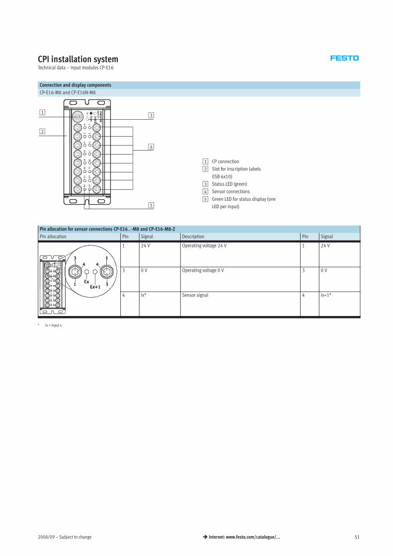
2008/09 – Subject to change 51 Internet: www.festo.com/catalogue/...
CPI installation systemTechnical data – Input modules CP-E16
Connection and display components
CP-E16-M8 and CP-E16N-M8
1
2
3
4
5
1 CP connection
2 Slot for inscription labels
(ISB 6x10)
3 Status LED (green)
4 Sensor connections
5 Green LED for status display (one
LED per input)
Pin allocation for sensor connections CP-E16…-M8 and CP-E16-M8-Z
Pin allocation Pin Signal Description Pin Signal
1 24 V Operating voltage 24 V 1 24 V
3 0 V Operating voltage 0 V 3 0 V
4 Ix* Sensor signal 4 Ix+1*
* Ix = Input x
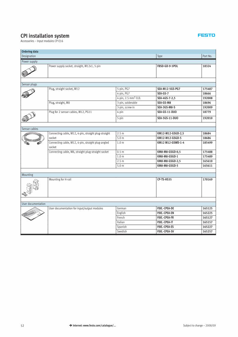
Subject to change – 2008/0952 Internet: www.festo.com/catalogue/...
CPI installation systemAccessories – Input modules CP-E16
Ordering data
Designation Type Part No.
Power supply
Power supply socket, straight, M12x1, 5-pin FBSD-GD-9-5POL 18324
Sensor plugs
Plug, straight socket, M12 5-pin, PG7 SEA-M12-5GS-PG7 175487g, g ,
4-pin, PG7 SEA-GS-7 18666
4-pin, 2.5 mm2 O.D. SEA-4GS-7-2,5 192008
Plug, straight, M8 3-pin, solderable SEA-GS-M8 18696g, g ,
3-pin, screw-in SEA-3GS-M8-S 192009
Plug for 2 sensor cables, M12, PG11 4-pin SEA-GS-11-DUO 18779
5-pin SEA-5GS-11-DUO 192010
Sensor cables
Connecting cable, M12, 4-pin, straight plug-straight 2.5 m KM12-M12-GSGD-2,5 18684g , , p , g p g g
socket 5.0 m KM12-M12-GSGD-5 18686
Connecting cable, M12, 4-pin, straight plug-angled
socket
1.0 m KM12 M12-GSWD-1-4 185499
Connecting cable, M8, straight plug-straight socket 0.5 m KM8-M8-GSGD-0,5 175488g , , g p g g
1.0 m KM8-M8-GSGD-1 175489
2.5 m KM8-M8-GSGD-2,5 165610
5.0 m KM8-M8-GSGD-5 165611
Mounting
Mounting for H-rail CP-TS-HS35 170169
User documentation
User documentation for input/output modules German P.BE.-CPEA-DE 165125p / p
English P.BE.-CPEA-EN 165225
French P.BE.-CPEA-FR 165127
Italian P.BE.-CPEA-IT 165157
Spanish P.BE.-CPEA-ES 165227
Swedish P.BE.-CPEA-SV 165257
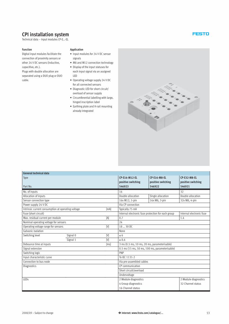
2008/09 – Subject to change 53 Internet: www.festo.com/catalogue/...
CPI installation systemTechnical data – Input modules CP-E…-EL
Function
Digital input modules facilitate the
connection of proximity sensors or
other 24 V DC sensors (inductive,
capacitive, etc.).
Plugs with double allocation are
separated using a DUO plug or DUO
cable.
Application
• Input modules for 24 V DC sensor
signals
• M8 and M12 connection technology
• Display of the input statuses for
each input signal via an assigned
LED
• Operating voltage supply 24 V DC
for all connected sensors
• Diagnostic LED for short circuit/
overload of sensor supply
• Circumferential labelling with large,
hinged inscription label
• Earthing plate and H-rail mounting
already integrated
General technical data
Type CP-E16-M12-EL
positive switching
CP-E16-M8-EL
positive switching
CP-E32-M8-EL
positive switching
Part No. 546923 546922 546921
No. of inputs 16 32
Allocation of inputs Double allocation Single allocation Double allocation
Sensor connection type 16x M12, 5-pin 16x M8, 3-pin 32x M8, 4-pin
Power supply 24 V DC Via CP connection
Intrinsic current consumption at operating voltage [mA] Typically 75 mA
Fuse (short circuit) Internal electronic fuse protection for each group Internal electronic fuse
Max. residual current per module [A] 0.7 1.4
Nominal operating voltage for sensors 24
Operating voltage range for sensors [V] 18 … 30 DC
Galvanic isolation None
Switching level Signal 0 [V] ≤ 6g
Signal 1 [V] ≥ 8.6
Debounce time at inputs [ms] 3 ms (0.5 ms, 10 ms, 20 ms, parameterisable)
Signal extension 0.5 ms (15 ms, 50 ms, 100 ms, parameterisable)
Switching logic PNP
Input characteristic curve To IEC 1131-2
Connection to bus node Via pre-assembled cables
Diagnostics CP communicationg
Short circuit/overload
Undervoltage
LEDs 2 Module diagnostics
4 Group diagnostics
16 Channel status
2 Module diagnostics
32 Channel status
Subject to change – 2008/0954 Internet: www.festo.com/catalogue/...
CPI installation systemTechnical data – Input modules CP-E…-EL
General technical data
Type CP-E16-M12-EL
positive switching
CP-E16-M8-EL
positive switching
CP-E32-M8-EL
positive switching
Part No. 546923 546922 546921
Dimensions (LxWxH) [mm] 143 x 104 x 30
Weight [g] 260
Operating conditions
Type CP-E16-M12-EL CP-E16-M8-EL CP-E32-M8-EL
Protection class to EN 60529 IP65 (when fully plugged in or fitted with protective cover)
Ambient temperature Operation [°C] –5 … +50p
Storage [°C] –20 … +70
Corrosion resistance class CRC1) 1
CE mark (see declaration of conformity) In accordance with EU EMC directive
Certification cULus listed (OL)
1) Corrosion resistance class 1 to Festo standard 940 070
Components requiring low corrosion resistance. Transport and storage protection. Parts that do not have primarily decorative surface requirements, e.g. in internal areas that are not visible or behind covers.
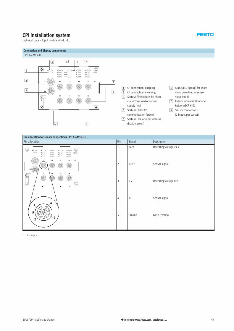
2008/09 – Subject to change 55 Internet: www.festo.com/catalogue/...
CPI installation systemTechnical data – Input modules CP-E…-EL
Connection and display components
CP-E16-M12-EL
1
2
5 6
77
7
74
3
81 CP connection, outgoing
2 CP connection, incoming
3 Status LED (module) for short
circuit/overload of sensor
supply (red)
4 Status LED for CP
communication (green)
5 Status LEDs for inputs (status
display, green)
6 Status LED (group) for short
circuit/overload of sensor
supply (red)
7 Fixture for inscription label
holder ASCF-H-E2
8 Sensor connections
(2 inputs per socket)
Pin allocation for sensor connections CP-E16-M12-EL
Pin allocation Pin Signal Description
1 24 V Operating voltage 24 V
2 Ix+1* Sensor signal
3 0 V Operating voltage 0 V
4 Ix* Sensor signal
5 Ground Earth terminal
* Ix = Input x
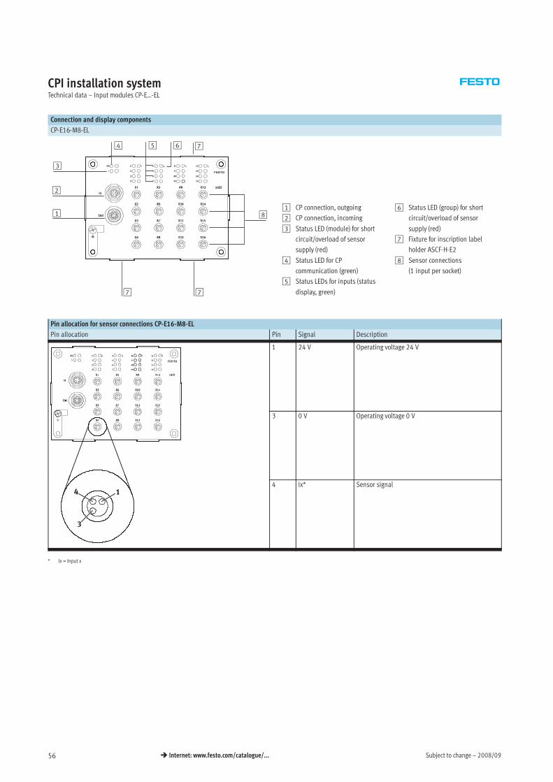
Subject to change – 2008/0956 Internet: www.festo.com/catalogue/...
CPI installation systemTechnical data – Input modules CP-E…-EL
Connection and display components
CP-E16-M8-EL
1
4
2
3
5 6
77
7
81 CP connection, outgoing
2 CP connection, incoming
3 Status LED (module) for short
circuit/overload of sensor
supply (red)
4 Status LED for CP
communication (green)
5 Status LEDs for inputs (status
display, green)
6 Status LED (group) for short
circuit/overload of sensor
supply (red)
7 Fixture for inscription label
holder ASCF-H-E2
8 Sensor connections
(1 input per socket)
Pin allocation for sensor connections CP-E16-M8-EL
Pin allocation Pin Signal Description
1 24 V Operating voltage 24 V
3 0 V Operating voltage 0 V
4 Ix* Sensor signal
* Ix = Input x
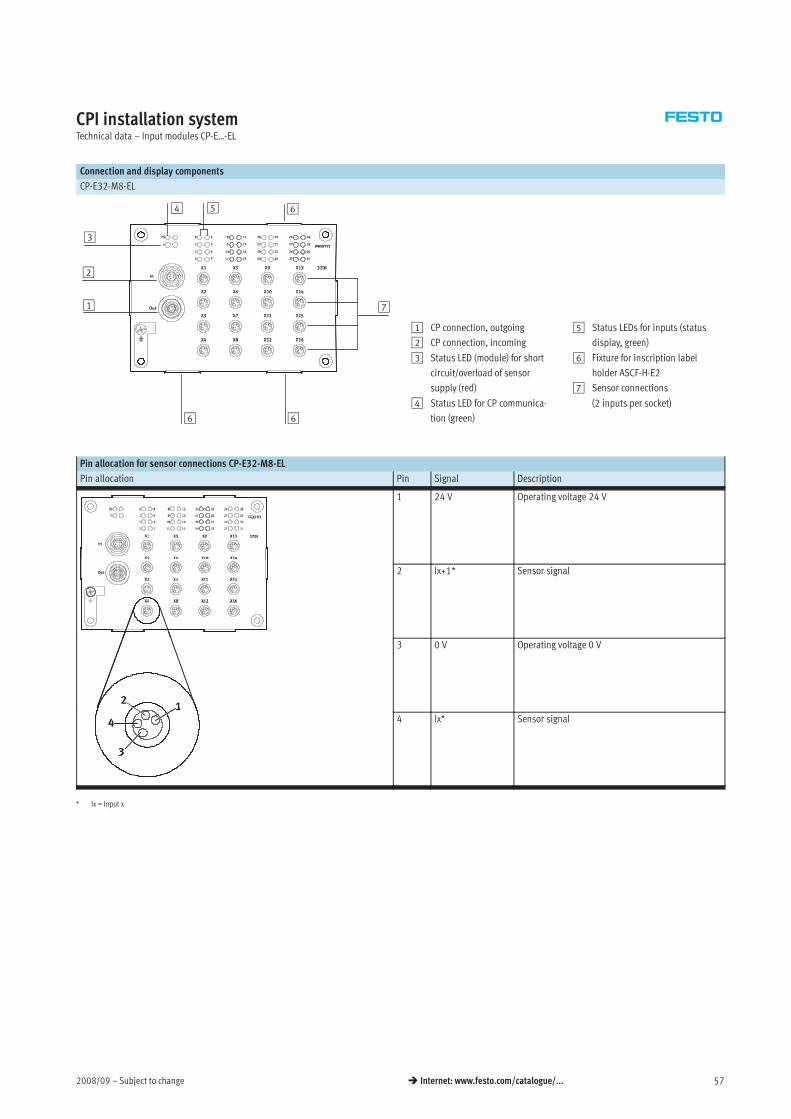
2008/09 – Subject to change 57 Internet: www.festo.com/catalogue/...
CPI installation systemTechnical data – Input modules CP-E…-EL
Connection and display components
CP-E32-M8-EL
1
4
2
3
5
66
6
7
1 CP connection, outgoing
2 CP connection, incoming
3 Status LED (module) for short
circuit/overload of sensor
supply (red)
4 Status LED for CP communica-
tion (green)
5 Status LEDs for inputs (status
display, green)
6 Fixture for inscription label
holder ASCF-H-E2
7 Sensor connections
(2 inputs per socket)
Pin allocation for sensor connections CP-E32-M8-EL
Pin allocation Pin Signal Description
1 24 V Operating voltage 24 V
2 Ix+1* Sensor signal
3 0 V Operating voltage 0 V
4 Ix* Sensor signal
* Ix = Input x
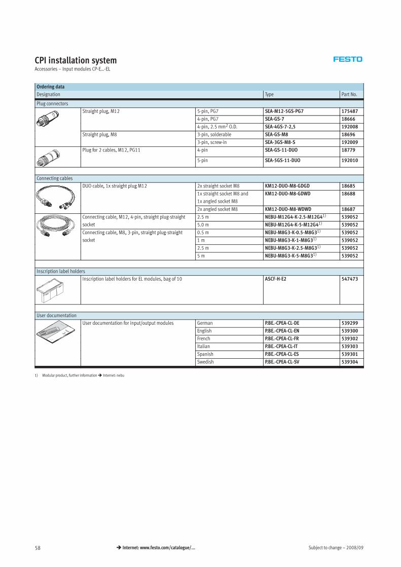
Subject to change – 2008/0958 Internet: www.festo.com/catalogue/...
CPI installation systemAccessories – Input modules CP-E…-EL
Ordering data
Designation Type Part No.
Plug connectors
Straight plug, M12 5-pin, PG7 SEA-M12-5GS-PG7 175487g p g,
4-pin, PG7 SEA-GS-7 18666
4-pin, 2.5 mm2 O.D. SEA-4GS-7-2,5 192008
Straight plug, M8 3-pin, solderable SEA-GS-M8 18696g p g,
3-pin, screw-in SEA-3GS-M8-S 192009
Plug for 2 cables, M12, PG11 4-pin SEA-GS-11-DUO 18779
5-pin SEA-5GS-11-DUO 192010
Connecting cables
DUO cable, 1x straight plug M12 2x straight socket M8 KM12-DUO-M8-GDGD 18685, g p g
1x straight socket M8 and
1x angled socket M8
KM12-DUO-M8-GDWD 18688
2x angled socket M8 KM12-DUO-M8-WDWD 18687
Connecting cable, M12, 4-pin, straight plug-straight 2.5 m NEBU-M12G4-K-2.5-M12G41) 539052g , , p , g p g g
socket 5.0 m NEBU-M12G4-K-5-M12G41) 539052
Connecting cable, M8, 3-pin, straight plug-straight 0.5 m NEBU-M8G3-K-0.5-M8G31) 539052g , , 3 p , g p g g
socket 1 m NEBU-M8G3-K-1-M8G31) 539052
2.5 m NEBU-M8G3-K-2.5-M8G31) 539052
5 m NEBU-M8G3-K-5-M8G31) 539052
Inscription label holders
Inscription label holders for EL modules, bag of 10 ASCF-H-E2 547473
User documentation
User documentation for input/output modules German P.BE.-CPEA-CL-DE 539299p / p
English P.BE.-CPEA-CL-EN 539300
French P.BE.-CPEA-CL-FR 539302
Italian P.BE.-CPEA-CL-IT 539303
Spanish P.BE.-CPEA-CL-ES 539301
Swedish P.BE.-CPEA-CL-SV 539304
1) Modular product, further information Internet: nebu
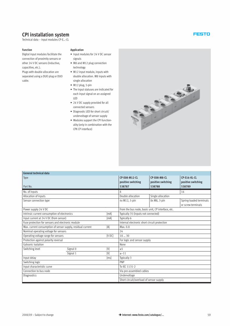
2008/09 – Subject to change 59 Internet: www.festo.com/catalogue/...
CPI installation systemTechnical data – Input modules CP-E…-CL
Function
Digital input modules facilitate the
connection of proximity sensors or
other 24 V DC sensors (inductive,
capacitive, etc.).
Plugs with double allocation are
separated using a DUO plug or DUO
cable.
Application
• Input modules for 24 V DC sensor
signals
• M8 and M12 plug connection
technology
• M12 input module, inputs with
double allocation. M8 inputs with
single allocation
• M12 plug, 5-pin
• The input statuses are indicated for
each input signal on an assigned
LED
• 24 V DC supply provided for all
connected sensors
• Diagnostic LED for short circuit/
undervoltage of sensor supply
• Modules support the CPI function-
ality (only in combination with the
CPX CP interface)
General technical data
Type CP-E08-M12-CL
positive switching
CP-E08-M8-CL
positive switching
CP-E16-KL-CL
positive switching
Part No. 538787 538788 538789
No. of inputs 8 16
Allocation of inputs Double allocation Single allocation
Sensor connection type 4x M12, 5-pin 8x M8, 3-pin Spring-loaded terminals
or screw terminals
Power supply 24 V DC From the bus node, basic unit, CP interface, etc.
Intrinsic current consumption of electronics [mA] Typically 35 (inputs not connected)
Input current at 24 V DC (from sensor) [mA] Typically 6
Fuse protection for sensors and electronic module Internal electronic short circuit protection
Max. current consumption of sensor supply, residual current [A] Max. 0.8
Nominal operating voltage for sensors 24
Operating voltage range for sensors [V DC] 18 … 30
Protection against polarity reversal For logic and sensor supply
Galvanic isolation None
Switching level Signal 0 [V] ≤5g
Signal 1 [V] ≥–11
Input delay [ms] Typically 3
Switching logic PNP
Input characteristic curve To IEC 1131-2
Connection to bus node Via pre-assembled cables
Diagnostics Undervoltageg
Short circuit/overload of sensor supply
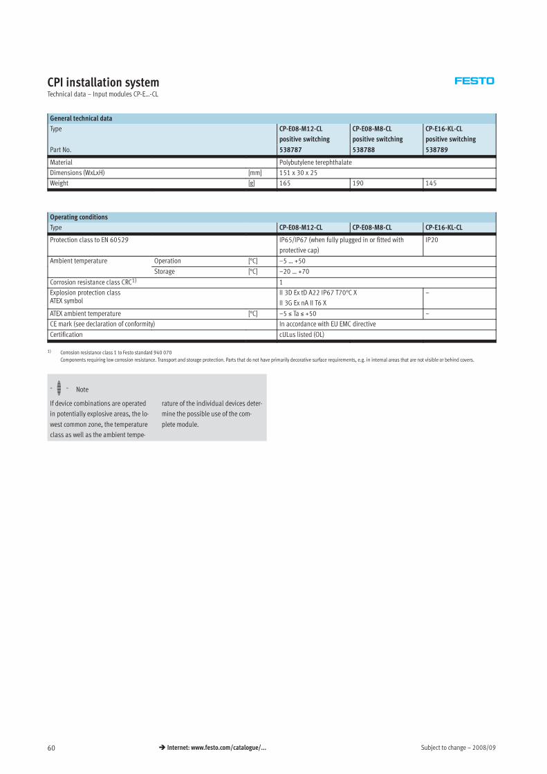
Subject to change – 2008/0960 Internet: www.festo.com/catalogue/...
CPI installation systemTechnical data – Input modules CP-E…-CL
General technical data
Type CP-E08-M12-CL
positive switching
CP-E08-M8-CL
positive switching
CP-E16-KL-CL
positive switching
Part No. 538787 538788 538789
Material Polybutylene terephthalate
Dimensions (WxLxH) [mm] 151 x 30 x 25
Weight [g] 165 190 145
Operating conditions
Type CP-E08-M12-CL CP-E08-M8-CL CP-E16-KL-CL
Protection class to EN 60529 IP65/IP67 (when fully plugged in or fitted with
protective cap)
IP20
Ambient temperature Operation [°C] –5 … +50p
Storage [°C] –20 … +70
Corrosion resistance class CRC1) 1
Explosion protection classATEX symbol
II 3D Ex tD A22 IP67 T70°C X
II 3G Ex nA II T6 X
–
ATEX ambient temperature [°C] –5 ≤ Ta ≤ +50 –
CE mark (see declaration of conformity) In accordance with EU EMC directive
Certification cULus listed (OL)
1) Corrosion resistance class 1 to Festo standard 940 070
Components requiring low corrosion resistance. Transport and storage protection. Parts that do not have primarily decorative surface requirements, e.g. in internal areas that are not visible or behind covers.
-H- Note
If device combinations are operated
in potentially explosive areas, the lo-
west common zone, the temperature
class as well as the ambient tempe-
rature of the individual devices deter-
mine the possible use of the com-
plete module.
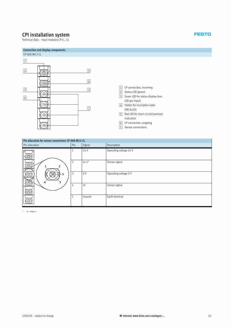
2008/09 – Subject to change 61 Internet: www.festo.com/catalogue/...
CPI installation systemTechnical data – Input modules CP-E…-CL
Connection and display components
CP-E08-M12-CL
1
4
5
7
3
2
6
31 CP connection, incoming
2 Status LED (green)
3 Green LED for status display (one
LED per input)
4 Holder for inscription label
(IBS 8x20)
5 Red LED for short circuit/overload
indication
6 CP connection, outgoing
7 Sensor connections
Pin allocation for sensor connections CP-E08-M12-CL
Pin allocation Pin Signal Description
1 24 V Operating voltage 24 V
2 Ix+1* Sensor signal
3 0 V Operating voltage 0 V
4 Ix* Sensor signal
5 Ground Earth terminal
* Ix = Input x
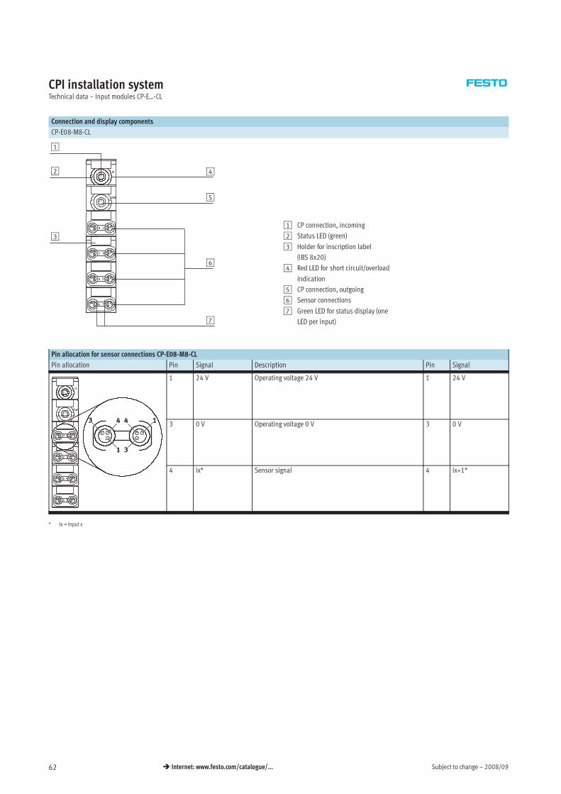
Subject to change – 2008/0962 Internet: www.festo.com/catalogue/...
CPI installation systemTechnical data – Input modules CP-E…-CL
Connection and display components
CP-E08-M8-CL
1
3
4
6
7
2
5
1 CP connection, incoming
2 Status LED (green)
3 Holder for inscription label
(IBS 8x20)
4 Red LED for short circuit/overload
indication
5 CP connection, outgoing
6 Sensor connections
7 Green LED for status display (one
LED per input)
Pin allocation for sensor connections CP-E08-M8-CL
Pin allocation Pin Signal Description Pin Signal
1 24 V Operating voltage 24 V 1 24 V
3 0 V Operating voltage 0 V 3 0 V
4 Ix* Sensor signal 4 Ix+1*
* Ix = Input x
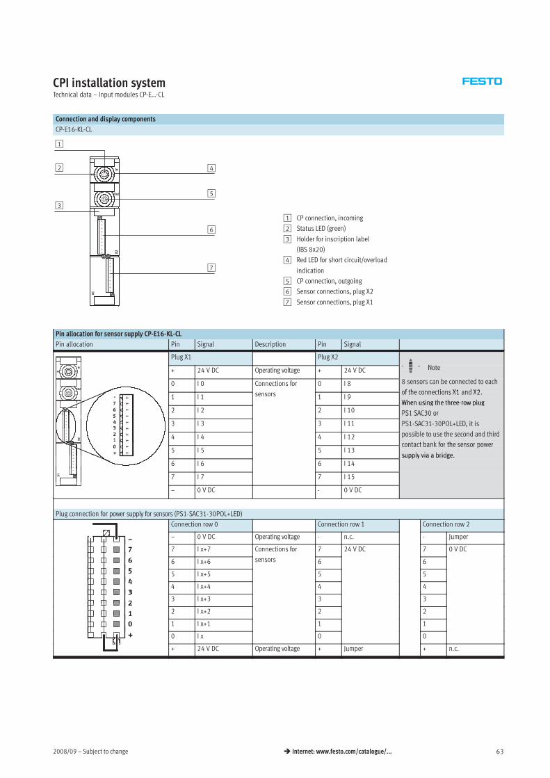
2008/09 – Subject to change 63 Internet: www.festo.com/catalogue/...
CPI installation systemTechnical data – Input modules CP-E…-CL
Connection and display components
CP-E16-KL-CL
1
3
4
6
2
5
7
1 CP connection, incoming
2 Status LED (green)
3 Holder for inscription label
(IBS 8x20)
4 Red LED for short circuit/overload
indication
5 CP connection, outgoing
6 Sensor connections, plug X2
7 Sensor connections, plug X1
Pin allocation for sensor supply CP-E16-KL-CL
Pin allocation Pin Signal Description Pin Signal
Plug X1 Plug X2
H+ 24 V DC Operating voltage + 24 V DC -H- Note
0 I 0 Connections for 0 I 8 8 sensors can be connected to each
of the connections X1 and X21 I 1 sensors 1 I 9
of the connections X1 and X2.
When using the three-row plug2 I 2 2 I 10
When using the three-row plug
PS1 SAC30 or
3 I 3 3 I 11
S S C30 o
PS1-SAC31-30POL+LED, it is
ibl h d d hi d4 I 4 4 I 12 possible to use the second and third
contact bank for the sensor power5 I 5 5 I 13
contact bank for the sensor power
supply via a bridge.6 I 6 6 I 14
supply via a bridge.
7 I 7 7 I 15
– 0 V DC - 0 V DC
Plug connection for power supply for sensors (PS1-SAC31-30POL+LED)
Connection row 0 Connection row 1 Connection row 2
– 0 V DC Operating voltage - n.c. - Jumper
7 I x+7 Connections for 7 24 V DC 7 0 V DC
6 I x+6 sensors 6 6
5 I x+5 5 5
4 I x+4 4 4
3 I x+3 3 3
2 I x+2 2 2
1 I x+1 1 1
0 I x 0 0
+ 24 V DC Operating voltage + Jumper + n.c.
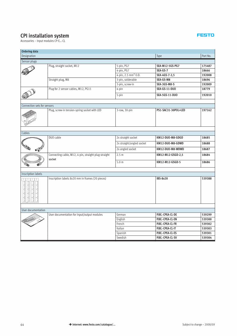
Subject to change – 2008/0964 Internet: www.festo.com/catalogue/...
CPI installation systemAccessories – Input modules CP-E…-CL
Ordering data
Designation Type Part No.
Sensor plugs
Plug, straight socket, M12 5-pin, PG7 SEA-M12-5GS-PG7 175487g, g ,
4-pin, PG7 SEA-GS-7 18666
4-pin, 2.5 mm2 O.D. SEA-4GS-7-2,5 192008
Straight plug, M8 3-pin, solderable SEA-GS-M8 18696g p g,
3-pin, screw-in SEA-3GS-M8-S 192009
Plug for 2 sensor cables, M12, PG11 4-pin SEA-GS-11-DUO 18779
5-pin SEA-5GS-11-DUO 192010
Connection sets for sensors
Plug, screw-in tension-spring socket with LED 3-row, 30-pin PS1-SAC31-30POL+LED 197162
Cables
DUO cable 2x straight socket KM12-DUO-M8-GDGD 18685
2x straight/angled socket KM12-DUO-M8-GDWD 18688
2x angled socket KM12-DUO-M8-WDWD 18687
Connecting cable, M12, 4-pin, straight plug-straight
socket
2.5 m KM12-M12-GSGD-2,5 18684
socket5.0 m KM12-M12-GSGD-5 18686
Inscription labels
Inscription labels 8x20 mm in frames (20 pieces) IBS-8x20 539388
User documentation
User documentation for input/output modules German P.BE.-CPEA-CL-DE 539299p / p
English P.BE.-CPEA-CL-EN 539300
French P.BE.-CPEA-CL-FR 539302
Italian P.BE.-CPEA-CL-IT 539303
Spanish P.BE.-CPEA-CL-ES 539301
Swedish P.BE.-CPEA-CL-SV 539304
2008/09 – Subject to change 65 Internet: www.festo.com/catalogue/...
CPI installation system
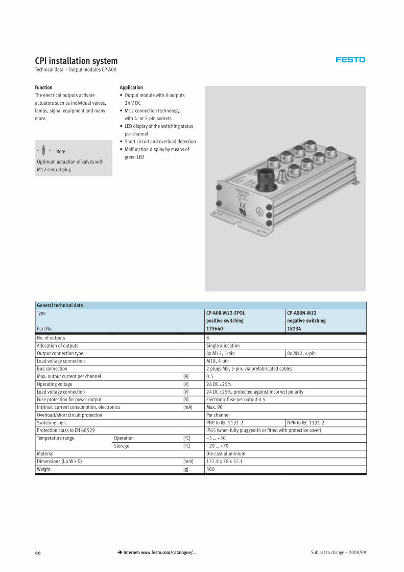
Subject to change – 2008/0966 Internet: www.festo.com/catalogue/...
CPI installation systemTechnical data – Output modules CP-A08
Function
The electrical outputs activate
actuators such as individual valves,
lamps, signal equipment and many
more.
Application
• Output module with 8 outputs
24 V DC
• M12 connection technology,
with 4- or 5-pin sockets
• LED display of the switching status
per channel
Sh i i d l d d i
-H- Note
Optimum actuation of valves with
M12 central plug.
• Short circuit and overload detection
• Malfunction display by means of
green LED
General technical data
Type CP-A08-M12-5POL
positive switching
CP-A08N-M12
negative switching
Part No. 175640 18234
No. of outputs 8
Allocation of outputs Single allocation
Output connection type 8x M12, 5-pin 8x M12, 4-pin
Load voltage connection M18, 4-pin
Bus connection 2 plugs M9, 5-pin, via prefabricated cables
Max. output current per channel [A] 0.5
Operating voltage [V] 24 DC ±25%
Load voltage connection [V] 24 DC ±25%, protected against incorrect polarity
Fuse protection for power output [A] Electronic fuse per output 0.5
Intrinsic current consumption, electronics [mA] Max. 90
Overload/short circuit protection Per channel
Switching logic PNP to IEC 1131-2 NPN to IEC 1131-2
Protection class to EN 60529 IP65 (when fully plugged-in or fitted with protective cover)
Temperature range Operation [°C] –5 … +50p g
Storage [°C] –20 … +70
Material Die-cast aluminium
Dimensions (L x W x D) [mm] 172.9 x 78 x 57.1
Weight [g] 500
2008/09 – Subject to change 67 Internet: www.festo.com/catalogue/...
CPI installation system
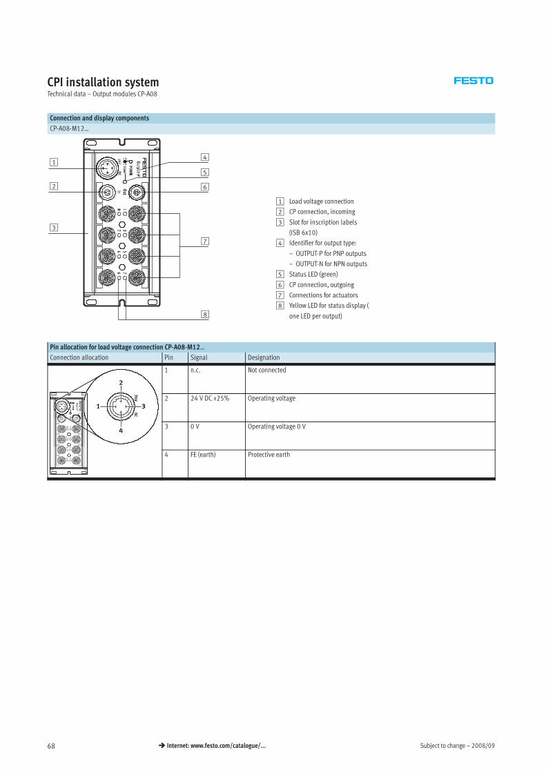
Subject to change – 2008/0968 Internet: www.festo.com/catalogue/...
CPI installation systemTechnical data – Output modules CP-A08
Connection and display components
CP-A08-M12…
1
3
5
7
8
62
4
1 Load voltage connection
2 CP connection, incoming
3 Slot for inscription labels
(ISB 6x10)
4 Identifier for output type:
– OUTPUT-P for PNP outputs
– OUTPUT-N for NPN outputs
5 Status LED (green)
6 CP connection, outgoing
7 Connections for actuators
8 Yellow LED for status display (
one LED per output)
Pin allocation for load voltage connection CP-A08-M12…
Connection allocation Pin Signal Designation
1 n.c. Not connected
2 24 V DC ±25% Operating voltage
3 0 V Operating voltage 0 V
4 FE (earth) Protective earth

2008/09 – Subject to change 69 Internet: www.festo.com/catalogue/...
CPI installation system
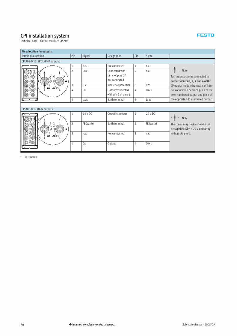
Subject to change – 2008/0970 Internet: www.festo.com/catalogue/...
CPI installation systemTechnical data – Output modules CP-A08
Pin allocation for outputs
Terminal allocation Pin Signal Designation Pin Signal
CP-A08-M12-5POL (PNP outputs)
1 n.c. Not connected 1 n.c.
H2 Ox+1 Connected with
pin 4 of plug 2/
not connected
2 n.c. -H- Note
Two outputs can be connected to
output sockets 0, 2, 4 and 6 of the
3 0 V Reference potential 3 0 V
output sockets 0, 2, 4 and 6 of the
CP output module by means of inter-
4 Ox Output/connected
with pin 2 of plug 1
4 Ox+1
CP output module by means of inter
nal connection between pin 2 of the
even numbered output and pin 4 of
5 Load Earth terminal 5 Load
p p
the opposite odd numbered output.
CP-A08-M12 (NPN outputs)
1 24 V DC Operating voltage 1 24 V DC
-H- Note
2 FE (earth) Earth terminal 2 FE (earth)
HThe consuming devices/load must
be supplied with a 24 V operating
3 n.c. Not connected 3 n.c.
pp p g
voltage via pin 1.
4 Ox Output 4 Ox+1
* Ox = Output x

2008/09 – Subject to change 71 Internet: www.festo.com/catalogue/...
CPI installation system
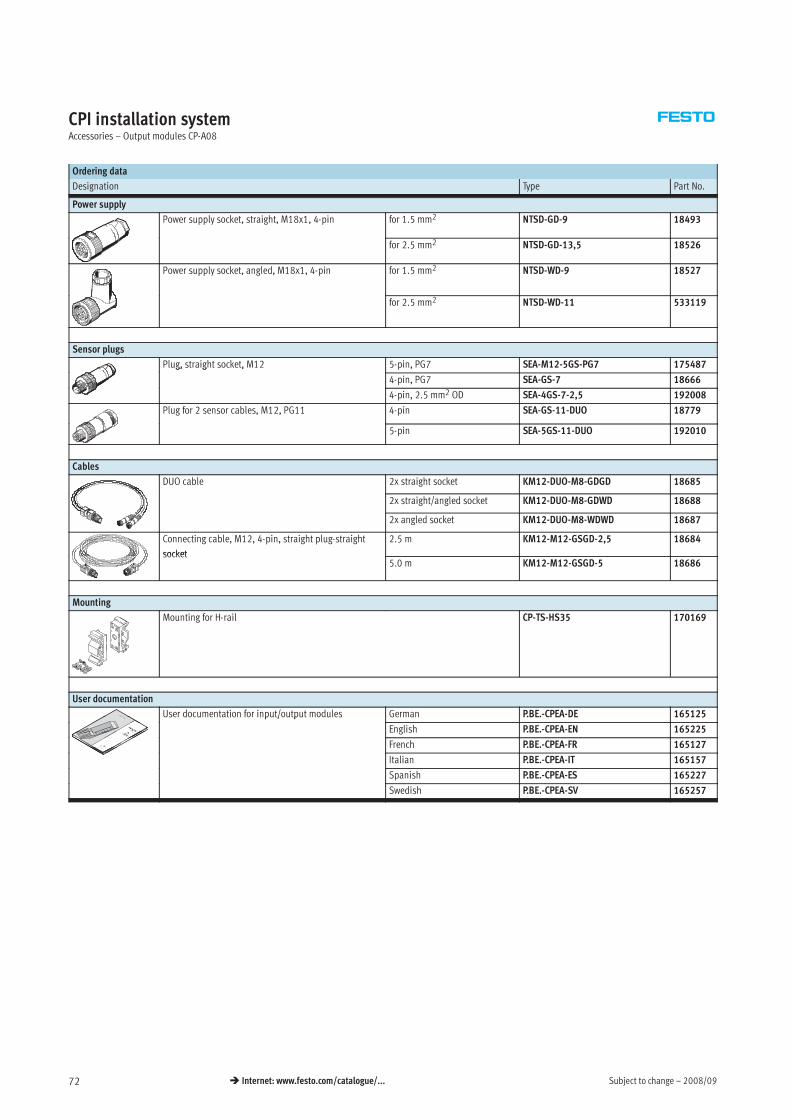
Subject to change – 2008/0972 Internet: www.festo.com/catalogue/...
CPI installation systemAccessories – Output modules CP-A08
Ordering data
Designation Type Part No.
Power supply
Power supply socket, straight, M18x1, 4-pin for 1.5 mm2 NTSD-GD-9 18493
for 2.5 mm2 NTSD-GD-13,5 18526
Power supply socket, angled, M18x1, 4-pin for 1.5 mm2 NTSD-WD-9 18527
for 2.5 mm2 NTSD-WD-11 533119
Sensor plugs
Plug, straight socket, M12 5-pin, PG7 SEA-M12-5GS-PG7 175487g, g ,
4-pin, PG7 SEA-GS-7 18666
4-pin, 2.5 mm2 OD SEA-4GS-7-2,5 192008
Plug for 2 sensor cables, M12, PG11 4-pin SEA-GS-11-DUO 18779
5-pin SEA-5GS-11-DUO 192010
Cables
DUO cable 2x straight socket KM12-DUO-M8-GDGD 18685
2x straight/angled socket KM12-DUO-M8-GDWD 18688
2x angled socket KM12-DUO-M8-WDWD 18687
Connecting cable, M12, 4-pin, straight plug-straight
socket
2.5 m KM12-M12-GSGD-2,5 18684
socket5.0 m KM12-M12-GSGD-5 18686
Mounting
Mounting for H-rail CP-TS-HS35 170169
User documentation
User documentation for input/output modules German P.BE.-CPEA-DE 165125p / p
English P.BE.-CPEA-EN 165225
French P.BE.-CPEA-FR 165127
Italian P.BE.-CPEA-IT 165157
Spanish P.BE.-CPEA-ES 165227
Swedish P.BE.-CPEA-SV 165257
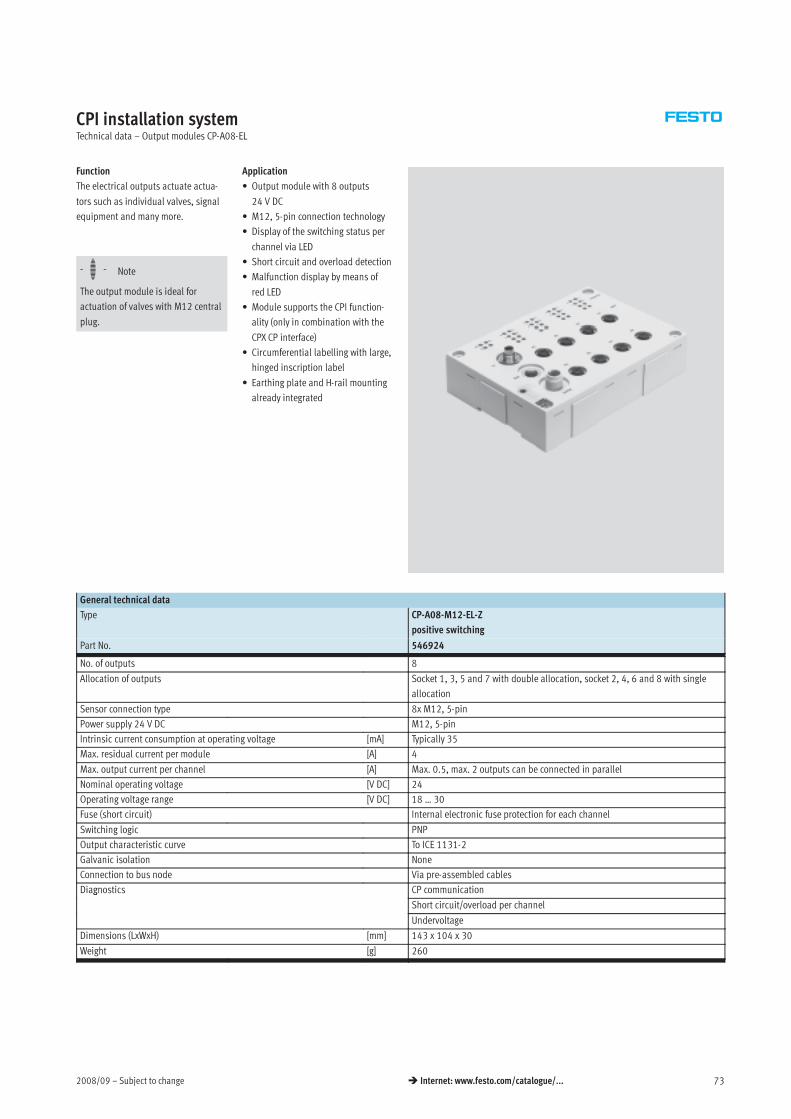
2008/09 – Subject to change 73 Internet: www.festo.com/catalogue/...
CPI installation systemTechnical data – Output modules CP-A08-EL
Function
The electrical outputs actuate actua-
tors such as individual valves, signal
equipment and many more.
Application
• Output module with 8 outputs
24 V DC
• M12, 5-pin connection technology
• Display of the switching status per
channel via LED
-H- Note
The output module is ideal for
actuation of valves with M12 central
plug.
• Short circuit and overload detection
• Malfunction display by means of
red LED
• Module supports the CPI function-
ality (only in combination with they ( y
CPX CP interface)
• Circumferential labelling with large,
hinged inscription label
• Earthing plate and H-rail mounting
already integrated
General technical data
Type CP-A08-M12-EL-Z
positive switching
Part No. 546924
No. of outputs 8
Allocation of outputs Socket 1, 3, 5 and 7 with double allocation, socket 2, 4, 6 and 8 with single
allocation
Sensor connection type 8x M12, 5-pin
Power supply 24 V DC M12, 5-pin
Intrinsic current consumption at operating voltage [mA] Typically 35
Max. residual current per module [A] 4
Max. output current per channel [A] Max. 0.5, max. 2 outputs can be connected in parallel
Nominal operating voltage [V DC] 24
Operating voltage range [V DC] 18 … 30
Fuse (short circuit) Internal electronic fuse protection for each channel
Switching logic PNP
Output characteristic curve To ICE 1131-2
Galvanic isolation None
Connection to bus node Via pre-assembled cables
Diagnostics CP communicationg
Short circuit/overload per channel
Undervoltage
Dimensions (LxWxH) [mm] 143 x 104 x 30
Weight [g] 260
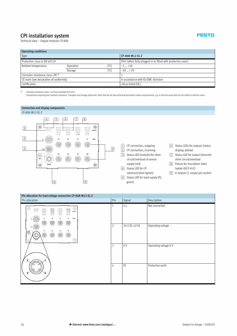
Subject to change – 2008/0974 Internet: www.festo.com/catalogue/...
CPI installation systemTechnical data – Output modules CP-A08
Operating conditions
Type CP-A08-M12-EL-Z
Protection class to EN 60529 IP65 (when fully plugged in or fitted with protective cover)
Ambient temperature Operation [°C] –5 … +50p
Storage [°C] –20 … +70
Corrosion resistance class CRC1) 1
CE mark (see declaration of conformity) In accordance with EU EMC directive
Certification cULus listed (OL)
1) Corrosion resistance class 1 to Festo standard 940 070
Components requiring low corrosion resistance. Transport and storage protection. Parts that do not have primarily decorative surface requirements, e.g. in internal areas that are not visible or behind covers.
Connection and display components
CP-A08-M12-EL-Z
1
2
6 7
88
4
3
5 8
91 CP connection, outgoing
2 CP connection, incoming
3 Status LED (module) for short
circuit/overload of sensor
supply (red)
4 Status LED for CP
communication (green)
5 Status LED for load supply (PL,
green)
6 Status LEDs for outputs (status
display, yellow)
7 Status LED for output (channel)
short circuit/overload
8 Fixture for inscription label
holder ASCF-H-E2
9 8 outputs (1 output per socket)
Pin allocation for load voltage connection CP-A08-M12-EL-Z
Pin allocation Pin Signal Description
1 n.c. Not connected
2 24 V DC ±25% Operating voltage
3 0 V Operating voltage 0 V
4 FE Protective earth
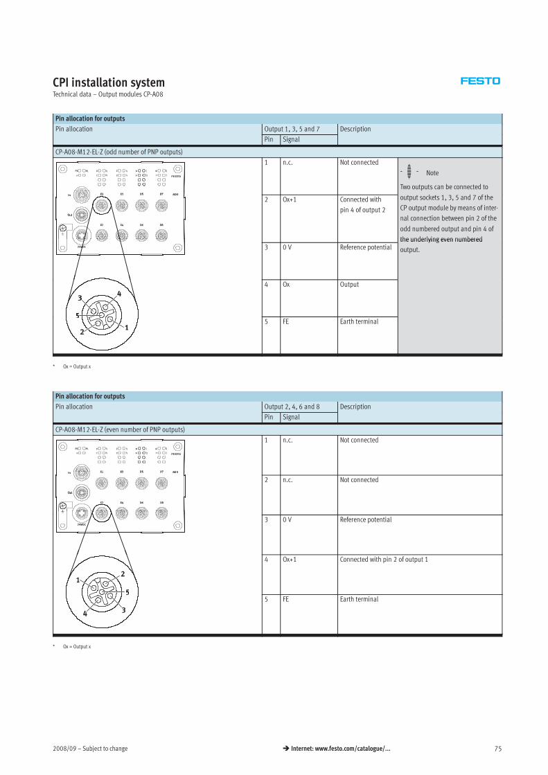
2008/09 – Subject to change 75 Internet: www.festo.com/catalogue/...
CPI installation systemTechnical data – Output modules CP-A08
Pin allocation for outputs
Pin allocation Output 1, 3, 5 and 7 Description
Pin Signal
CP-A08-M12-EL-Z (odd number of PNP outputs)
1 n.c. Not connected
-H- Note
Two outputs can be connected to
2 Ox+1 Connected with
pin 4 of output 2
output sockets 1, 3, 5 and 7 of the
CP output module by means of inter-
nal connection between pin 2 of the
odd numbered output and pin 4 of
the underlying even numbered3 0 V Reference potential
the underlying even numbered
output.
4 Ox Output
5 FE Earth terminal
* Ox = Output x
Pin allocation for outputs
Pin allocation Output 2, 4, 6 and 8 Description
Pin Signal
CP-A08-M12-EL-Z (even number of PNP outputs)
1 n.c. Not connected
2 n.c. Not connected
3 0 V Reference potential
4 Ox+1 Connected with pin 2 of output 1
5 FE Earth terminal
* Ox = Output x
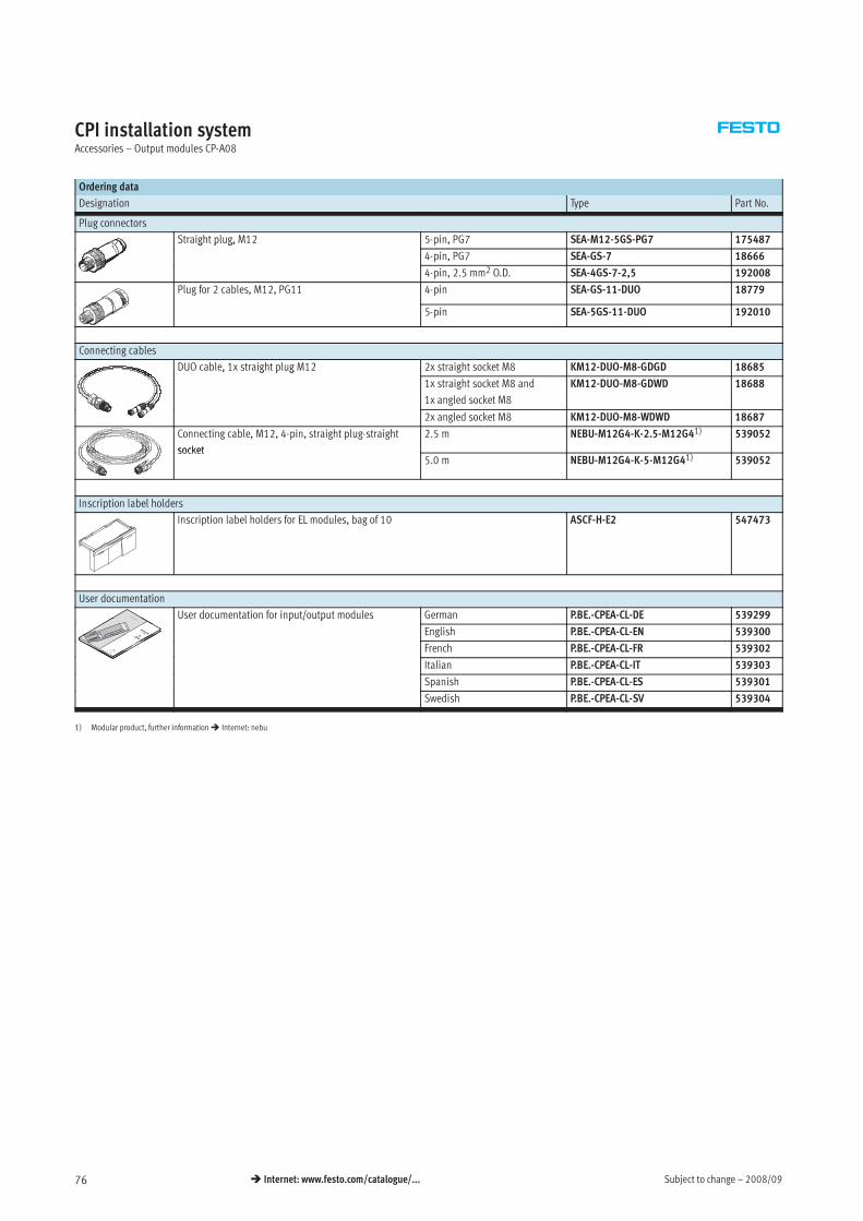
Subject to change – 2008/0976 Internet: www.festo.com/catalogue/...
CPI installation systemAccessories – Output modules CP-A08
Ordering data
Designation Type Part No.
Plug connectors
Straight plug, M12 5-pin, PG7 SEA-M12-5GS-PG7 175487g p g,
4-pin, PG7 SEA-GS-7 18666
4-pin, 2.5 mm2 O.D. SEA-4GS-7-2,5 192008
Plug for 2 cables, M12, PG11 4-pin SEA-GS-11-DUO 18779
5-pin SEA-5GS-11-DUO 192010
Connecting cables
DUO cable, 1x straight plug M12 2x straight socket M8 KM12-DUO-M8-GDGD 18685, g p g
1x straight socket M8 and
1x angled socket M8
KM12-DUO-M8-GDWD 18688
2x angled socket M8 KM12-DUO-M8-WDWD 18687
Connecting cable, M12, 4-pin, straight plug-straight
socket
2.5 m NEBU-M12G4-K-2.5-M12G41) 539052
socket5.0 m NEBU-M12G4-K-5-M12G41) 539052
Inscription label holders
Inscription label holders for EL modules, bag of 10 ASCF-H-E2 547473
User documentation
User documentation for input/output modules German P.BE.-CPEA-CL-DE 539299p / p
English P.BE.-CPEA-CL-EN 539300
French P.BE.-CPEA-CL-FR 539302
Italian P.BE.-CPEA-CL-IT 539303
Spanish P.BE.-CPEA-CL-ES 539301
Swedish P.BE.-CPEA-CL-SV 539304
1) Modular product, further information Internet: nebu
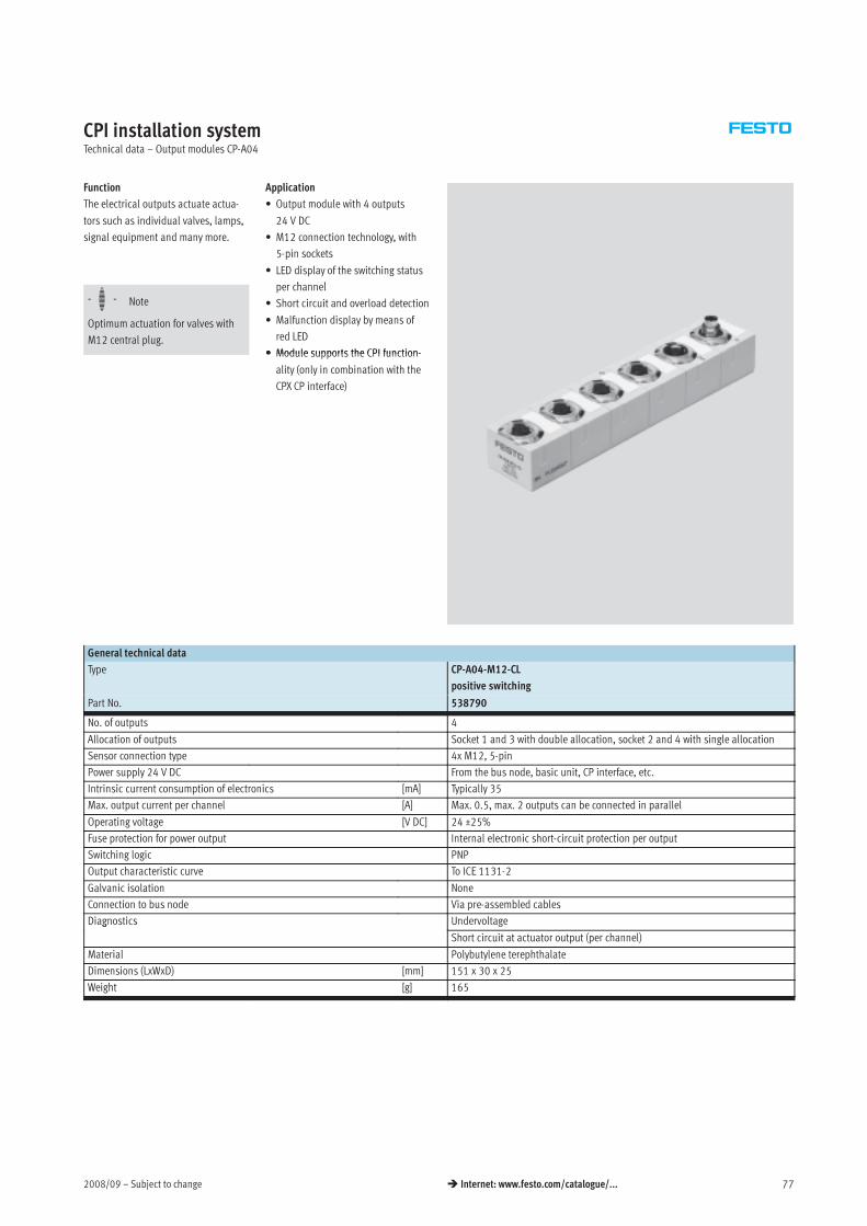
2008/09 – Subject to change 77 Internet: www.festo.com/catalogue/...
CPI installation systemTechnical data – Output modules CP-A04
Function
The electrical outputs actuate actua-
tors such as individual valves, lamps,
signal equipment and many more.
Application
• Output module with 4 outputs
24 V DC
• M12 connection technology, with
5-pin sockets
• LED display of the switching status
h l
-H- Note
Optimum actuation for valves with
M12 central plug.
per channel
• Short circuit and overload detection
• Malfunction display by means of
red LED
• Module supports the CPI function-• Module supports the CPI function-
ality (only in combination with the
CPX CP interface)
General technical data
Type CP-A04-M12-CL
positive switching
Part No. 538790
No. of outputs 4
Allocation of outputs Socket 1 and 3 with double allocation, socket 2 and 4 with single allocation
Sensor connection type 4x M12, 5-pin
Power supply 24 V DC From the bus node, basic unit, CP interface, etc.
Intrinsic current consumption of electronics [mA] Typically 35
Max. output current per channel [A] Max. 0.5, max. 2 outputs can be connected in parallel
Operating voltage [V DC] 24 ±25%
Fuse protection for power output Internal electronic short-circuit protection per output
Switching logic PNP
Output characteristic curve To ICE 1131-2
Galvanic isolation None
Connection to bus node Via pre-assembled cables
Diagnostics Undervoltageg
Short circuit at actuator output (per channel)
Material Polybutylene terephthalate
Dimensions (LxWxD) [mm] 151 x 30 x 25
Weight [g] 165
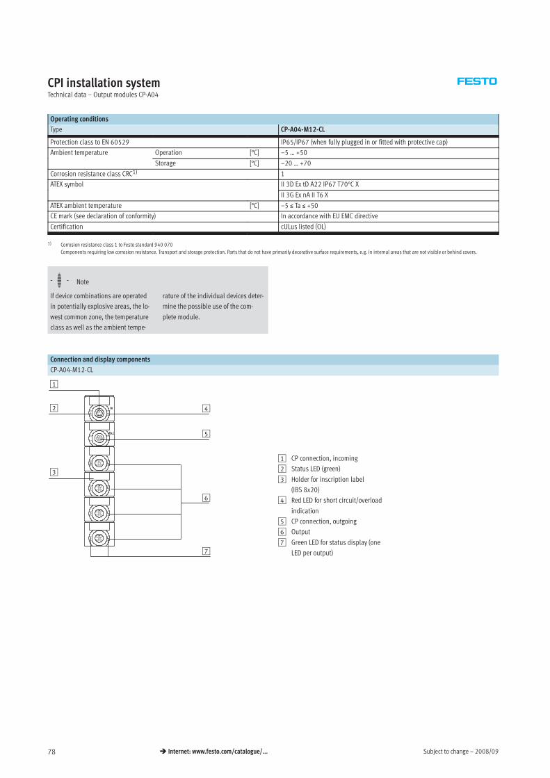
Subject to change – 2008/0978 Internet: www.festo.com/catalogue/...
CPI installation systemTechnical data – Output modules CP-A04
Operating conditions
Type CP-A04-M12-CL
Protection class to EN 60529 IP65/IP67 (when fully plugged in or fitted with protective cap)
Ambient temperature Operation [°C] –5 … +50p
Storage [°C] –20 … +70
Corrosion resistance class CRC1) 1
ATEX symbol II 3D Ex tD A22 IP67 T70°C Xy
II 3G Ex nA II T6 X
ATEX ambient temperature [°C] –5 ≤ Ta ≤ +50
CE mark (see declaration of conformity) In accordance with EU EMC directive
Certification cULus listed (OL)
1) Corrosion resistance class 1 to Festo standard 940 070
Components requiring low corrosion resistance. Transport and storage protection. Parts that do not have primarily decorative surface requirements, e.g. in internal areas that are not visible or behind covers.
-H- Note
If device combinations are operated
in potentially explosive areas, the lo-
west common zone, the temperature
class as well as the ambient tempe-
rature of the individual devices deter-
mine the possible use of the com-
plete module.
Connection and display components
CP-A04-M12-CL
1
3
4
6
7
2
5
1 CP connection, incoming
2 Status LED (green)
3 Holder for inscription label
(IBS 8x20)
4 Red LED for short circuit/overload
indication
5 CP connection, outgoing
6 Output
7 Green LED for status display (one
LED per output)
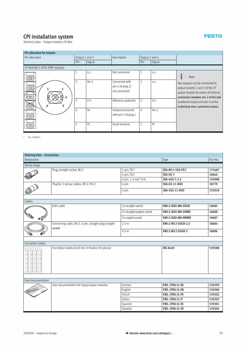
2008/09 – Subject to change 79 Internet: www.festo.com/catalogue/...
CPI installation systemTechnical data – Output modules CP-A04
Pin allocation for outputs
Pin allocation Output 1 and 3 Description Output 2 and 4
Pin Signal Pin Signal
CP-A08-M12-5POL (PNP outputs)
1 n.c. Not connected 1 n.c.
-H- Note
2 Ox+1 Connected with
pin 4 of plug 2/
not connected
2 n.c.
HTwo outputs can be connected to
output sockets 1 and 3 of the CP
output module by means of internal
connection between pin 2 of the odd3 0 V Reference potential 3 0 V
connection between pin 2 of the odd
numbered output and pin 4 of the
underlying even numbered output.4 Ox Output/connected
with pin 2 of plug 1
4 Ox+1underlying even numbered output.
5 FE Earth terminal 5 FE
* Ox = Output x
Ordering data – Accessories
Designation Type Part No.
Sensor plugs
Plug, straight socket, M12 5-pin, PG7 SEA-M12-5GS-PG7 175487g, g ,
4-pin, PG7 SEA-GS-7 18666
4-pin, 2.5 mm2 O.D. SEA-4GS-7-2,5 192008
Plug for 2 sensor cables, M12, PG11 4-pin SEA-GS-11-DUO 18779
5-pin SEA-5GS-11-DUO 192010
Cables
DUO cable 2x straight socket KM12-DUO-M8-GDGD 18685
2x straight/angled socket KM12-DUO-M8-GDWD 18688
2x angled socket KM12-DUO-M8-WDWD 18687
Connecting cable, M12, 4-pin, straight plug-straight
socket
2.5 m KM12-M12-GSGD-2,5 18684
socket5.0 m KM12-M12-GSGD-5 18686
Inscription labels
Inscription labels 8x20 mm in frames (20 pieces) IBS-8x20 539388
User documentation
User documentation for input/output modules German P.BE.-CPEA-CL-DE 539299p / p
English P.BE.-CPEA-CL-EN 539300
French P.BE.-CPEA-CL-FR 539302
Italian P.BE.-CPEA-CL-IT 539303
Spanish P.BE.-CPEA-CL-ES 539301
Swedish P.BE.-CPEA-CL-SV 539304
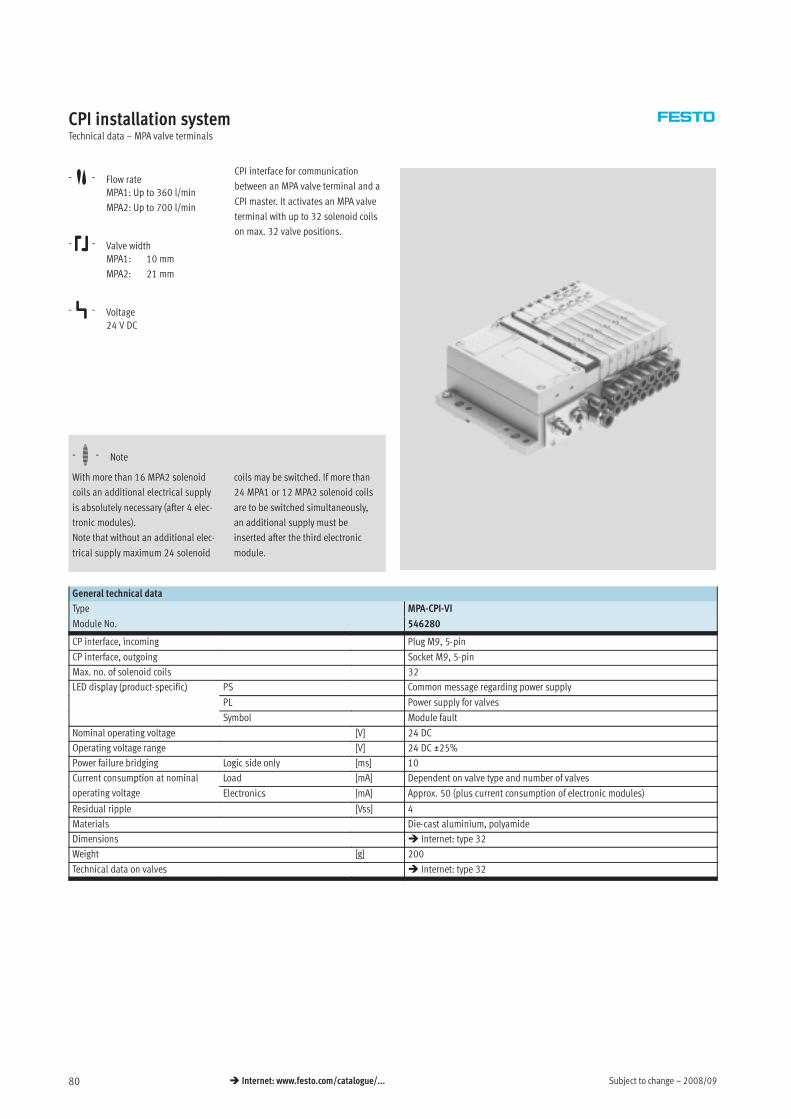
Subject to change – 2008/0980 Internet: www.festo.com/catalogue/...
CPI installation systemTechnical data – MPA valve terminals
-M- Flow rate
MPA1: Up to 360 l/min
MPA2: Up to 700 l/min
-K- Valve width
MPA1: 10 mm
MPA2: 21 mm
-P- Voltage
24 V DC
CPI interface for communication
between an MPA valve terminal and a
CPI master. It activates an MPA valve
terminal with up to 32 solenoid coils
on max. 32 valve positions.
-H- Note
With more than 16 MPA2 solenoid
coils an additional electrical supply
is absolutely necessary (after 4 elec-
tronic modules).
Note that without an additional elec-
trical supply maximum 24 solenoid
coils may be switched. If more than
24 MPA1 or 12 MPA2 solenoid coils
are to be switched simultaneously,
an additional supply must be
inserted after the third electronic
module.
General technical data
Type MPA-CPI-VI
Module No. 546280
CP interface, incoming Plug M9, 5-pin
CP interface, outgoing Socket M9, 5-pin
Max. no. of solenoid coils 32
LED display (product-specific) PS Common message regarding power supplyp y (p p )
PL Power supply for valves
Symbol Module fault
Nominal operating voltage [V] 24 DC
Operating voltage range [V] 24 DC _25%
Power failure bridging Logic side only [ms] 10
Current consumption at nominal Load [mA] Dependent on valve type and number of valvesp
operating voltage Electronics [mA] Approx. 50 (plus current consumption of electronic modules)
Residual ripple [Vss] 4
Materials Die-cast aluminium, polyamide
Dimensions Internet: type 32
Weight [g] 200
Technical data on valves Internet: type 32
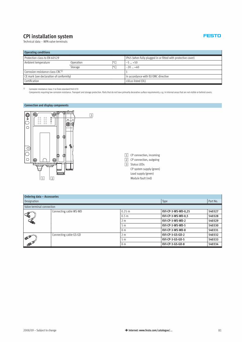
2008/09 – Subject to change 81 Internet: www.festo.com/catalogue/...
CPI installation systemTechnical data – MPA valve terminals
Operating conditions
Protection class to EN 60529 IP65 (when fully plugged in or fitted with protective cover)
Ambient temperature Operation [°C] –5 … +50p
Storage [°C] –20 … +40
Corrosion resistance class CRC1) 1
CE mark (see declaration of conformity) In accordance with EU EMC directive
Certification cULus listed (OL)
1) Corrosion resistance class 1 to Festo standard 940 070
Components requiring low corrosion resistance. Transport and storage protection. Parts that do not have primarily decorative surface requirements, e.g. in internal areas that are not visible or behind covers.
Connection and display components
1
3
2
1 CP connection, incoming
2 CP connection, outgoing
3 Status LEDs
CP system supply (green)
Load supply (green)
Module fault (red)
Ordering data – Accessories
Designation Type Part No.
Valve terminal connection
Connecting cable WS-WD 0.25 m KVI-CP-3-WS-WD-0,25 540327g
0.5 m KVI-CP-3-WS-WD-0,5 540328
2 m KVI-CP-3-WS-WD-2 540329
5 m KVI-CP-3-WS-WD-5 540330
8 m KVI-CP-3-WS-WD-8 540331
Connecting cable GS-GD 2 m KVI-CP-3-GS-GD-2 540332g
5 m KVI-CP-3-GS-GD-5 540333
8 m KVI-CP-3-GS-GD-8 540334
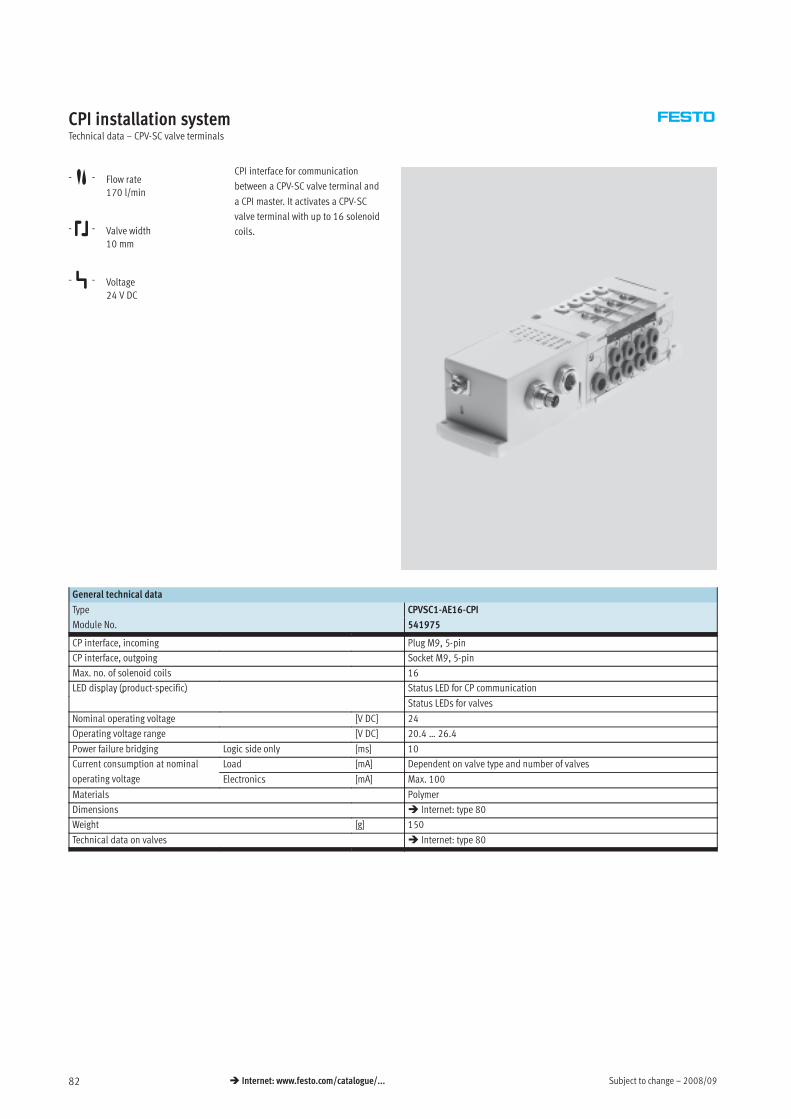
Subject to change – 2008/0982 Internet: www.festo.com/catalogue/...
CPI installation systemTechnical data – CPV-SC valve terminals
-M- Flow rate
170 l/min
-K- Valve width
10 mm
-P- Voltage
24 V DC
CPI interface for communication
between a CPV-SC valve terminal and
a CPI master. It activates a CPV-SC
valve terminal with up to 16 solenoid
coils.
General technical data
Type CPVSC1-AE16-CPI
Module No. 541975
CP interface, incoming Plug M9, 5-pin
CP interface, outgoing Socket M9, 5-pin
Max. no. of solenoid coils 16
LED display (product-specific) Status LED for CP communicationp y (p p )
Status LEDs for valves
Nominal operating voltage [V DC] 24
Operating voltage range [V DC] 20.4 … 26.4
Power failure bridging Logic side only [ms] 10
Current consumption at nominal Load [mA] Dependent on valve type and number of valvesp
operating voltage Electronics [mA] Max. 100
Materials Polymer
Dimensions Internet: type 80
Weight [g] 150
Technical data on valves Internet: type 80
2008/09 – Subject to change 83 Internet: www.festo.com/catalogue/...
CPI installation systemTechnical data – CPV-SC valve terminals
Operating conditions
Protection class to EN 60529 IP40 (when fully plugged in or fitted with protective cover)
Ambient temperature Operation [°C] –5 … +50p
Storage [°C] –20 … +40
Corrosion resistance class CRC1) 1
CE mark (see declaration of conformity) In accordance with EU EMC directive
Certification c UL us Recognized (OL)
1) Corrosion resistance class 1 to Festo standard 940 070
Components requiring low corrosion resistance. Transport and storage protection. Parts that do not have primarily decorative surface requirements, e.g. in internal areas that are not visible or behind covers.
Connection and display components
132
4
1 CP connection, incoming
2 CP connection, outgoing
3 Status LED for CP
communication
4 Status LEDs for valves
Ordering data – Accessories
Designation Type Part No.
Valve terminal connection
Connecting cable WS-WD 0.25 m KVI-CP-3-WS-WD-0,25 540327g
0.5 m KVI-CP-3-WS-WD-0,5 540328
2 m KVI-CP-3-WS-WD-2 540329
5 m KVI-CP-3-WS-WD-5 540330
8 m KVI-CP-3-WS-WD-8 540331
Connecting cable GS-GD 2 m KVI-CP-3-GS-GD-2 540332g
5 m KVI-CP-3-GS-GD-5 540333
8 m KVI-CP-3-GS-GD-8 540334
Subject to change – 2008/0684 Internet: www.festo.com/catalogue/...
CPI installation systemTechnical data
Dimensions – Fieldbus node/control block Download CAD data www.festo.com
CPX-FB… /CPX-FEC and CPX-CP-4-FB
1 Mounting holes
2 Earthing screw
3 H-rail
4 H-rail mounting
5 CPX fieldbus node or CPX control
block
6 CPX-CP interface
2008/06 – Subject to change 85 Internet: www.festo.com/catalogue/...
CPI installation systemTechnical data
Dimensions Download CAD data www.festo.com
Fieldbus node
1 Slots for inscription label 2 Earthing screw
3 H-rail with support base
-H- Note
The dimensions are valid for the
fieldbus node types:
• CP-FB05-E
• CP-FB06-E
• CP-FB11-E
• CP-FB13-E
Different height ~110 (incl. fieldbus
plug) for
• CP-FB06-E with M23
• CP-FB11-E with M12
• CP-FB13-E with 2x M12
Subject to change – 2008/0686 Internet: www.festo.com/catalogue/...
CPI installation systemTechnical data
Dimensions – Sturdy input modules Download CAD data www.festo.com
CP-E16-M8
1 Slots for inscription label 2 Earthing screw M3 3 Protective cap (included in
scope of delivery)
4 H-rail with support base
CP-E16-M8-Z
1 Slots for inscription label 2 Earthing screw M3 3 Protective cap (included in
scope of delivery)
4 H-rail with support base
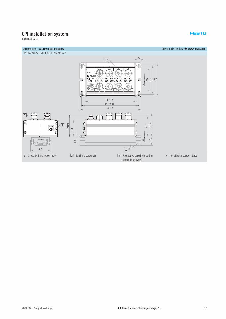
2008/06 – Subject to change 87 Internet: www.festo.com/catalogue/...
CPI installation systemTechnical data
Dimensions – Sturdy input modules Download CAD data www.festo.com
CP-E16-M12x2-5POL/CP-E16N-M12x2
1 Slots for inscription label 2 Earthing screw M3 3 Protective cap (included in
scope of delivery)
4 H-rail with support base
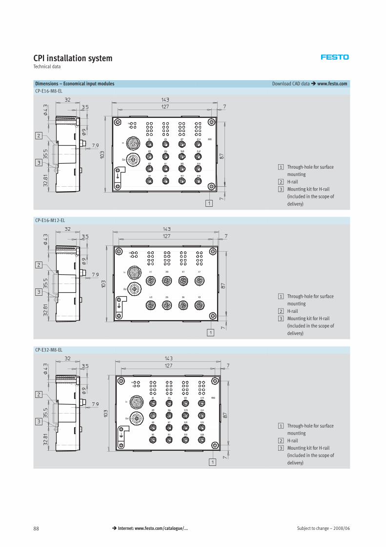
Subject to change – 2008/0688 Internet: www.festo.com/catalogue/...
CPI installation systemTechnical data
Dimensions – Economical input modules Download CAD data www.festo.com
CP-E16-M8-EL
1 Through-hole for surface
mounting
2 H-rail
3 Mounting kit for H-rail
(included in the scope of
delivery)
CP-E16-M12-EL
1 Through-hole for surface
mounting
2 H-rail
3 Mounting kit for H-rail
(included in the scope of
delivery)
CP-E32-M8-EL
1 Through-hole for surface
mounting
2 H-rail
3 Mounting kit for H-rail
(included in the scope of
delivery)
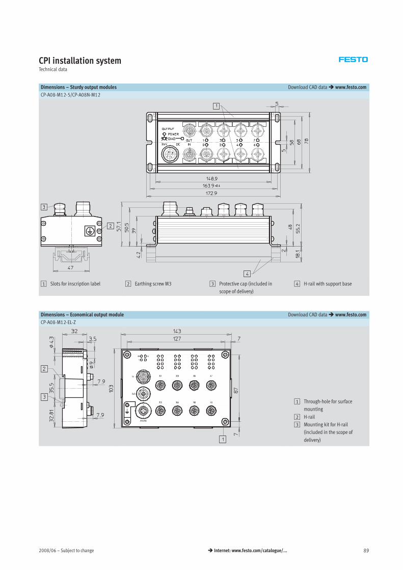
2008/06 – Subject to change 89 Internet: www.festo.com/catalogue/...
CPI installation systemTechnical data
Dimensions – Sturdy output modules Download CAD data www.festo.com
CP-A08-M12-5/CP-A08N-M12
1 Slots for inscription label 2 Earthing screw M3 3 Protective cap (included in
scope of delivery)
4 H-rail with support base
Dimensions – Economical output module Download CAD data www.festo.com
CP-A08-M12-EL-Z
1 Through-hole for surface
mounting
2 H-rail
3 Mounting kit for H-rail
(included in the scope of
delivery)
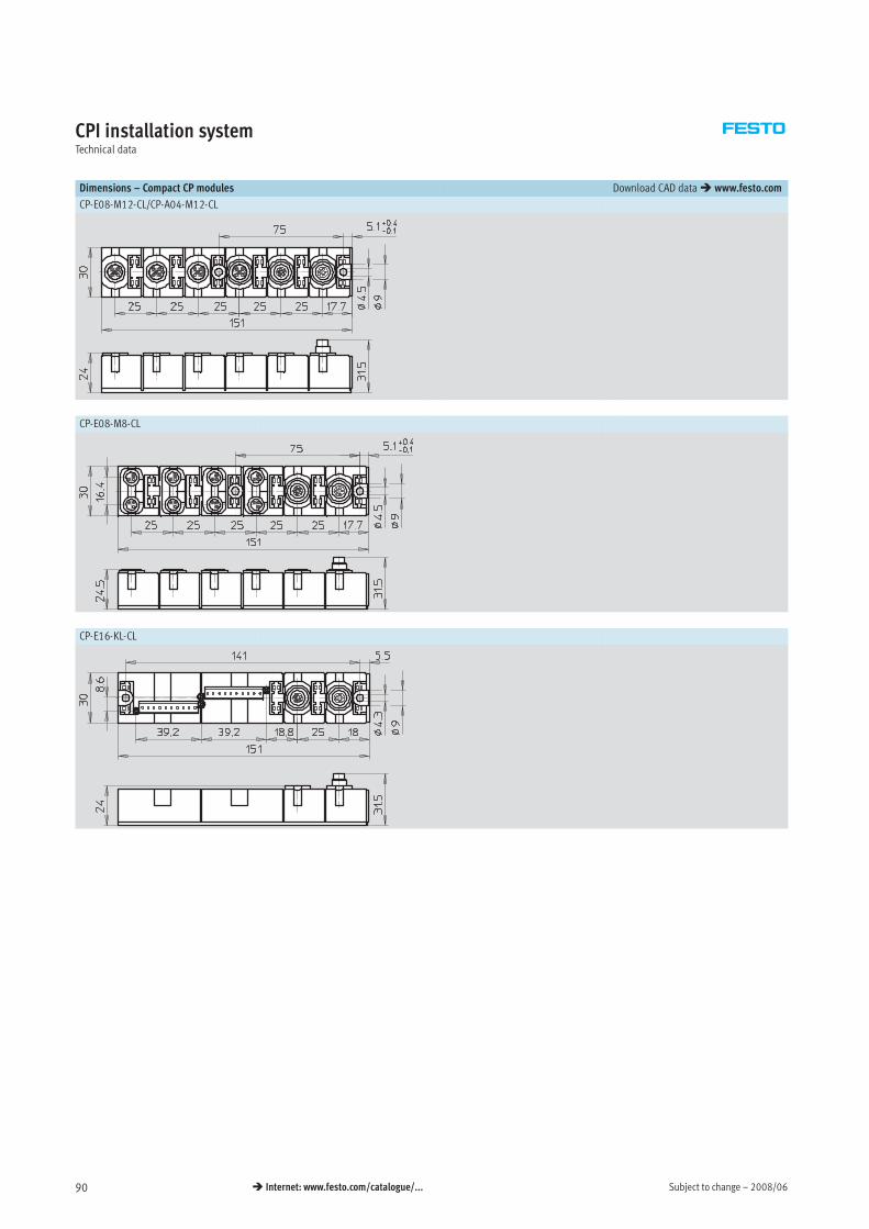
Subject to change – 2008/0690 Internet: www.festo.com/catalogue/...
CPI installation systemTechnical data
Dimensions – Compact CP modules Download CAD data www.festo.com
CP-E08-M12-CL/CP-A04-M12-CL
CP-E08-M8-CL
CP-E16-KL-CL
2008/06 – Subject to change 91 Internet: www.festo.com/catalogue/...
CPI installation systemOrder processing information
Configuration guidelines
The CPI system supports a certain
number of modules per CP string
depending on the type of the CP
master and the CP modules
connected.
CP masters and CP modules can be
split into two different groups:
• With CPI functionality
• Without CPI functionality
CP modules with CPI functionality CP modules without CPI functionality
CP modules with CPI functionality offer
the following features:
• Incoming and outgoing CP interface
• Any arrangement of the modules
within a CP string
• Max. 4 modules per CP string
• Max. 32 inputs and outputs can be
connected to each string depending
on the version
Sturdy CP modules offer the following
features:
• CP valve terminals and CP output
modules have an incoming and
outgoing CP interface
• CP input modules only have an in-
coming CP interface and therefore
can only be positioned at the end of
a CP string
• All CP modules with CPI functional-
ity can also be connected to CP
masters without extended
functionality
Information on using CP modules with and without CPI functionality
A mixture of CP modules with and
without CPI functionality is possible.
The following must be noted in this
regard:
• Only one input module without CPI
functionality is possible per CP
string (at the end of a CP string)
• Only one CP valve terminal or out-
put module without CPI functional-
ity is possible per CP string (any
point in the CP string)
• Free positions in the CP string can
be filled by CP modules with CPI
functionality (max. 4 modules)
-H- Note
The cable length for any given string
may not exceed 10 m.
Connecting cables are available in
lengths of 0.25 m, 0.5 m, 2 m, 5 m
and 8 m
94
The maximum number of inputs
and outputs that can be connected
is 32 each (sum of all CP modules
on a CP string), regardless of the
type of CP module (with or without
CPI functionality).
Order processing
There are two ways of placing an order
for the electrical CPI installation
system:
• By completing the order form on the
following pages
• Digitally using the valve terminal
configurator
Please note that the CP strings must
be allocated in ascending numerical
order, i.e. starting with string 1,
followed by string 2, etc. without
omitting any numbers.
To correctly allocate a CP string,
proceed as follows:
• First select a connecting cable of
appropriate length.
• Then select an input/output
module.
• Continue in this way until the string
is fully allocated (max. 4 strings for
CP modules with extended
functionality).
The valve terminals are configured
separately:
• CPV valve terminal
CPV10/14/18-VI-FB-….
Internet: type 10
• MPA valve terminals
MPA-CPI-VI
Internet: type 32
• CPV-SC valve terminals
CPVSC1-AE16-CPI
Internet: type 80
• CPA valve terminals
CPA10/14-IFB-CP….
Internet: type 12

Subject to change – 2008/0992 Internet: www.festo.com/catalogue/...
CPI installation systemAccessories
Ordering data
Designation Type Part No.
Plug connectors – Power supply
Power supply socket, straight, M18x1, 4-pin for 1.5 mm2 NTSD-GD-9 18493
for 2.5 mm2 NTSD-GD-13,5 18526
Power supply socket, angled, M18x1, 4-pin for 1.5 mm2 NTSD-WD-9 18527
for 2.5 mm2 NTSD-WD-11 533119
Power supply socket for CPX system supply 7/8† connection, 5-pin NECU-G78G5-C2 543107
7/8† connection, 4-pin NECU-G78G4-C2 543108
Connection sets for power supply and sensors
Plug, screw-in tension-spring socket 3-row, 30-pin PS1 SAC30 197161
Plug, screw-in tension-spring socket with LED 3-row, 30-pin PS1-SAC31-30POL+LED 197162
Sensor plugs
Plug M12, straight socket 5-pin, PG7 SEA-M12-5GS-PG7 175487g , g
4-pin, PG7 SEA-GS-7 18666
4-pin, 2.5 mm2 O.D. SEA-4GS-7-2,5 192008
Plug M8, straight 3-pin, solderable SEA-GS-M8 18696g , g
3-pin, screw-in SEA-3GS-M8-S 192009
Plug M12 for 2 sensor cables, PG11 4-pin SEA-GS-11-DUO 18779
5-pin SEA-5GS-11-DUO 192010
Push-in T-connector 2x socket M8, 3-pin
1x plug M8, 4-pin
NEDU-M8D3-M8T4 544391
Push-in T-connector 2x socket M12, 5-pin
1x plug M12, 4-pin
NEDU-M12D5-M12T4 541596
2008/09 – Subject to change 93 Internet: www.festo.com/catalogue/...
CPI installation systemAccessories
Ordering data
Designation Type Part No.
Plug connectors – Fieldbus connection
Sub-D plug for INTERBUS Incoming FBS-SUB-9-BU-IB-B 532218p g
Outgoing FBS-SUB-9-GS-IB-B 532217
Sub-D plug for DeviceNet/CANopen FBS-SUB-9-BU-2x5POL-B 532219
Sub-D plug for Profibus DP FBS-SUB-9-GS-DP-B 532216
Sub-D plug for CC-Link FBS-SUB-9-GS-2x4POL-B 532220
Sub-D plug FBS-SUB-9-GS-1x9POL-B 534497
Bus connection M12, 5-pin, adapter (B-coded) for Profibus DP FBA-2-M12-5POL-RK 533118
Bus connection Micro Style 2xM12, 5-pin, for DeviceNet/CANopen FBA-2-M12-5POL 525632
Socket M12, 5-pin, for Micro Style connection FBSD-GD-9-5POL 18324
Plug M12, 5-pin, for Micro Style connection FBS-M12-5GS-PG9 175380
Bus connection M12x1, 4-pin (D-coded) for Ethernet NECU-M-S-D12G4-C2-ET 543109
Connection block M12 adapter (B-coded) for Profibus DP CPX-AB-2-M12-RK-DP 541519
Connection block M12 adapter (B-coded) for INTERBUS CPX-AB-2-M12-RK-IB 534505
Bus connection Open Style for 5-pin terminal strip for DeviceNet/CANopen FBA-1-SL-5POL 525634
Bus connection 5-pin terminal strip for DeviceNet/CANopen FBSD-KL-2x5POL 525635
Bus connection screw terminal for CC-Link FBA-1-KL-5POL 197962
RJ45/plug FBS-RJ45-8-GS 534494
Accessories – Fieldbus connection
Threaded sleeve, 4 pieces UNC4-40/M3x6 533000
Cover for CPX-AB-8-KL-4POL (IP65/67)
– 8 cable through-feeds M9
– 1 cable through-feed for multi-pin plug
AK-8KL 538219
Screening plate for M12 connections CPX-AB-S-4-M12 526184
Earthing element for right-hand/left-hand end plates (5 pieces) CPX-EPFE-EV 538892
Subject to change – 2008/0994 Internet: www.festo.com/catalogue/...
CPI installation systemAccessories
Ordering data
Designation Type Part No.
Connecting cables
DUO cable M12-2xM8, 4-pin/2x3-pin 2x straight socket KM12-DUO-M8-GDGD 18685
2x straight/angled socket KM12-DUO-M8-GDWD 18688
2x angled socket KM12-DUO-M8-WDWD 18687
Connecting cable M8-M8, straight plug-straight socket 0.5 m KM8-M8-GSGD-0,5 175488g , g p g g
1.0 m KM8-M8-GSGD-1 175489
2.5 m KM8-M8-GSGD-2,5 165610
5.0 m KM8-M8-GSGD-5 165611
Extension cable M12-M12, 5-pin, straight plug-straight 1.5 m KV-M12-M12-1,5 529044, 5 p , g p g g
socket 3.5 m KV-M12-M12-3,5 530901
Connecting cable M12-M12, 4-pin, straight plug- 2.5 m KM12-M12-GSGD-2,5 18684g , p , g p g
straight socket 5.0 m KM12-M12-GSGD-5 18686
Connecting cable M12-M12, 4-pin, straight plug-
angled socket
1.0 m KM12-M12-GSWD-1-4 185499
Modular system for connecting cables NEBU-…
Internet: nebu
–
Programming cable KDI-PPA-3-BU9 151915
Connecting cable FED, pre-assembled at one end FEC-KBG7 539642
Connecting cable FED, pre-assembled at both ends FEC-KBG8 539643
Connecting cable – CP modules
Connecting cable WS-WD, angled plug-angled socket 0.25 m KVI-CP-3-WS-WD-0,25 540327g , g p g g
0.5 m KVI-CP-3-WS-WD-0,5 540328
2 m KVI-CP-3-WS-WD-2 540329
5 m KVI-CP-3-WS-WD-5 540330
8 m KVI-CP-3-WS-WD-8 540331
Connecting cable GS-GD, straight plug-straight socket 2 m KVI-CP-3-GS-GD-2 540332g , g p g g
5 m KVI-CP-3-GS-GD-5 540333
8 m KVI-CP-3-GS-GD-8 540334
Connector plug for CP cable (control cabinet implementation) KVI-CP-3-SSD 543252
2008/09 – Subject to change 95 Internet: www.festo.com/catalogue/...
CPI installation systemAccessories
Ordering data
Designation Type Part No.
Protective caps
Inspection cover, transparent AK-SUB-9/15-B 533334
Cover for RJ45 connection AK-Rj45 534496
Protective cap for sealing unused sockets (10 pieces) for M8 connections ISK-M8 177672p g ( p )
M9 FLANSCHDOSE SER.712 356684
for M12 connections ISK-M12 165592
Mounting attachments
Retainer CPX-MMI CPX-MMI-1-H 534705
Mounting for H-rail, CPX-MMI CPX-MMI-1-NRH 536689
Mounting for H-rail, CP modules CP-TS-HS35 170169
Mounting for H-rail IBGH-03-4,0 18649
Inscription labels
Inscription labels 6x10 mm in frames (64 pieces) IBS-6x10 18576
Inscription labels 8x20 mm in frames (20 pieces) for compact modules (CP-…-CL) IBS-8x20 539388
Inscription label holders for EL modules, bag of 10 ASCF-H-E2 547473
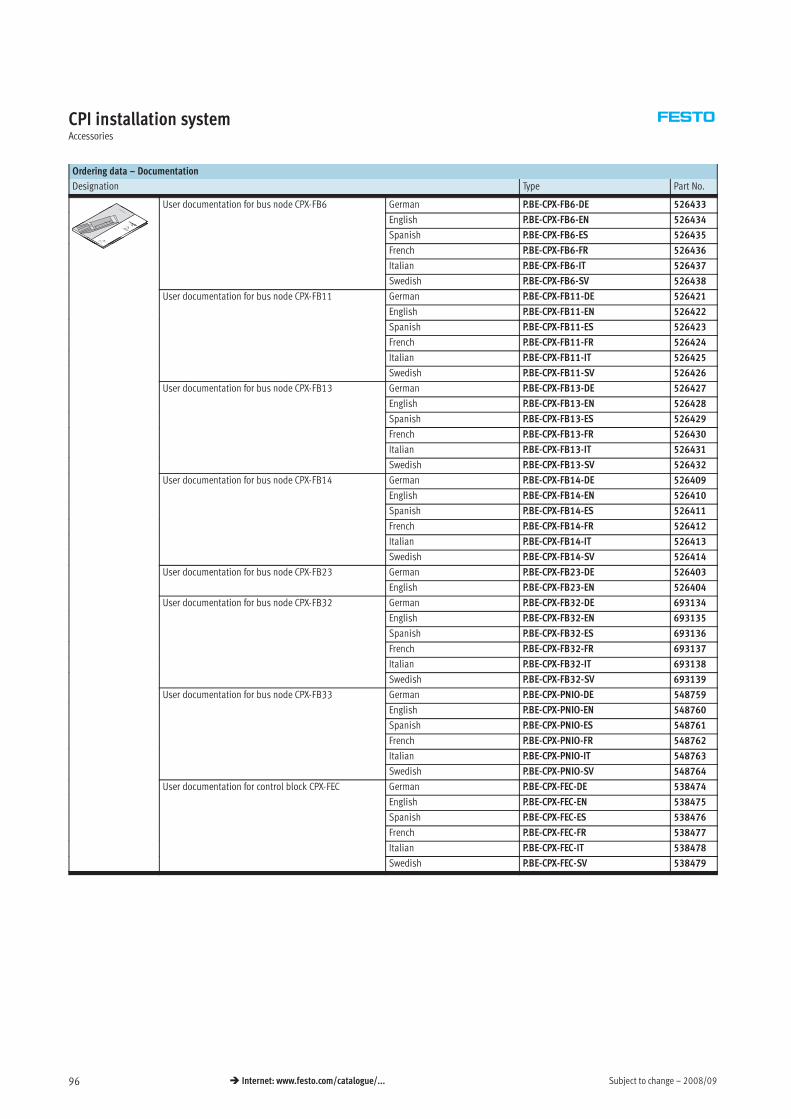
Subject to change – 2008/0996 Internet: www.festo.com/catalogue/...
CPI installation systemAccessories
Ordering data – Documentation
Designation Type Part No.
User documentation for bus node CPX-FB6 German P.BE-CPX-FB6-DE 526433
English P.BE-CPX-FB6-EN 526434
Spanish P.BE-CPX-FB6-ES 526435
French P.BE-CPX-FB6-FR 526436
Italian P.BE-CPX-FB6-IT 526437
Swedish P.BE-CPX-FB6-SV 526438
User documentation for bus node CPX-FB11 German P.BE-CPX-FB11-DE 526421
English P.BE-CPX-FB11-EN 526422
Spanish P.BE-CPX-FB11-ES 526423
French P.BE-CPX-FB11-FR 526424
Italian P.BE-CPX-FB11-IT 526425
Swedish P.BE-CPX-FB11-SV 526426
User documentation for bus node CPX-FB13 German P.BE-CPX-FB13-DE 5264273
English P.BE-CPX-FB13-EN 526428
Spanish P.BE-CPX-FB13-ES 526429
French P.BE-CPX-FB13-FR 526430
Italian P.BE-CPX-FB13-IT 526431
Swedish P.BE-CPX-FB13-SV 526432
User documentation for bus node CPX-FB14 German P.BE-CPX-FB14-DE 526409
English P.BE-CPX-FB14-EN 526410
Spanish P.BE-CPX-FB14-ES 526411
French P.BE-CPX-FB14-FR 526412
Italian P.BE-CPX-FB14-IT 526413
Swedish P.BE-CPX-FB14-SV 526414
User documentation for bus node CPX-FB23 German P.BE-CPX-FB23-DE 5264033
English P.BE-CPX-FB23-EN 526404
User documentation for bus node CPX-FB32 German P.BE-CPX-FB32-DE 6931343
English P.BE-CPX-FB32-EN 693135
Spanish P.BE-CPX-FB32-ES 693136
French P.BE-CPX-FB32-FR 693137
Italian P.BE-CPX-FB32-IT 693138
Swedish P.BE-CPX-FB32-SV 693139
User documentation for bus node CPX-FB33 German P.BE-CPX-PNIO-DE 54875933
English P.BE-CPX-PNIO-EN 548760
Spanish P.BE-CPX-PNIO-ES 548761
French P.BE-CPX-PNIO-FR 548762
Italian P.BE-CPX-PNIO-IT 548763
Swedish P.BE-CPX-PNIO-SV 548764
User documentation for control block CPX-FEC German P.BE-CPX-FEC-DE 538474
English P.BE-CPX-FEC-EN 538475
Spanish P.BE-CPX-FEC-ES 538476
French P.BE-CPX-FEC-FR 538477
Italian P.BE-CPX-FEC-IT 538478
Swedish P.BE-CPX-FEC-SV 538479
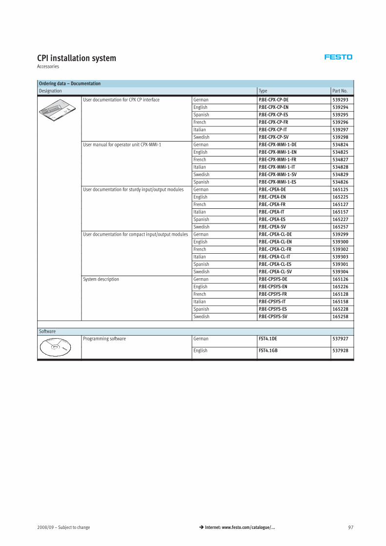
2008/09 – Subject to change 97 Internet: www.festo.com/catalogue/...
CPI installation systemAccessories
Ordering data – Documentation
Designation Type Part No.
User documentation for CPX CP interface German P.BE-CPX-CP-DE 539293
English P.BE-CPX-CP-EN 539294
Spanish P.BE-CPX-CP-ES 539295
French P.BE-CPX-CP-FR 539296
Italian P.BE-CPX-CP-IT 539297
Swedish P.BE-CPX-CP-SV 539298
User manual for operator unit CPX-MMI-1 German P.BE-CPX-MMI-1-DE 534824p
English P.BE-CPX-MMI-1-EN 534825
French P.BE-CPX-MMI-1-FR 534827
Italian P.BE-CPX-MMI-1-IT 534828
Swedish P.BE-CPX-MMI-1-SV 534829
Spanish P.BE-CPX-MMI-1-ES 534826
User documentation for sturdy input/output modules German P.BE.-CPEA-DE 165125y p / p
English P.BE.-CPEA-EN 165225
French P.BE.-CPEA-FR 165127
Italian P.BE.-CPEA-IT 165157
Spanish P.BE.-CPEA-ES 165227
Swedish P.BE.-CPEA-SV 165257
User documentation for compact input/output modules German P.BE.-CPEA-CL-DE 539299p p / p
English P.BE.-CPEA-CL-EN 539300
French P.BE.-CPEA-CL-FR 539302
Italian P.BE.-CPEA-CL-IT 539303
Spanish P.BE.-CPEA-CL-ES 539301
Swedish P.BE.-CPEA-CL-SV 539304
System description German P.BE-CPSYS-DE 165126y p
English P.BE-CPSYS-EN 165226
French P.BE-CPSYS-FR 165128
Italian P.BE-CPSYS-IT 165158
Spanish P.BE-CPSYS-ES 165228
Swedish P.BE-CPSYS-SV 165258
Software
Programming software German FST4.1DE 537927
English FST4.1GB 537928

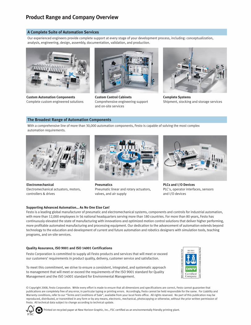
Product Range and Company Overview
The Broadest Range of Automation Components
With a comprehensive line of more than 30,000 automation components, Festo is capable of solving the most complex
automation requirements.
Supporting Advanced Automation… As No One Else Can!
Festo is a leading global manufacturer of pneumatic and electromechanical systems, components and controls for industrial automation,
with more than 12,000 employees in 56 national headquarters serving more than 180 countries. For more than 80 years, Festo has
continuously elevated the state of manufacturing with innovations and optimized motion control solutions that deliver higher performing,
more profitable automated manufacturing and processing equipment. Our dedication to the advancement of automation extends beyond
technology to the education and development of current and future automation and robotics designers with simulation tools, teaching
programs, and on-site services.
Quality Assurance, ISO 9001 and ISO 14001 Certifications
Festo Corporation is committed to supply all Festo products and services that will meet or exceed
our customers’ requirements in product quality, delivery, customer service and satisfaction.
To meet this commitment, we strive to ensure a consistent, integrated, and systematic approach
to management that will meet or exceed the requirements of the ISO 9001 standard for Quality
Management and the ISO 14001 standard for Environmental Management.
PLCs and I/O Devices
PLC's, operator interfaces, sensors
and I/O devices
Pneumatics
Pneumatic linear and rotary actuators,
valves, and air supply
Electromechanical
Electromechanical actuators, motors,
controllers & drives
A Complete Suite of Automation Services
Our experienced engineers provide complete support at every stage of your development process, including: conceptualization,
analysis, engineering, design, assembly, documentation, validation, and production.
Complete Systems
Shipment, stocking and storage services
Custom Control Cabinets
Comprehensive engineering support
and on-site services
Custom Automation Components
Complete custom engineered solutions
© Copyright 2008, Festo Corporation. While every effort is made to ensure that all dimensions and specifications are correct, Festo cannot guarantee that
publications are completely free of any error, in particular typing or printing errors. Accordingly, Festo cannot be held responsible for the same. For Liability and
Warranty conditions, refer to our “Terms and Conditions of Sale”, available from your local Festo office. All rights reserved. No part of this publication may be
reproduced, distributed, or transmitted in any form or by any means, electronic, mechanical, photocopying or otherwise, without the prior written permission of
Festo. All technical data subject to change according to technical update.
Printed on recycled paper at New Horizon Graphic, Inc., FSC certified as an environmentally friendly printing plant.
Festo North America
United States
Customer Resource Center502 Earth City Expy., Suite 125Earth City, MO 63045
For ordering assistance, or to find your nearest Festo Distributor,Call: 1.800.99.FESTOFax: 1.800.96.FESTOEmail: [email protected]
For technical support,Call: 1.866.GO.FESTOFax: 1.800.96.FESTOEmail: [email protected]
HeadquartersFesto Corporation395 Moreland RoadP.O. Box 18023Hauppauge, NY 11788www.festo.com/us
Sales Offices
AppletonN. 922 Tower View Drive, Suite NGreenville, WI 54942
Boston120 Presidential Way, Suite 330Woburn, MA 01801
Chicago1441 East Business Center DriveMt. Prospect, IL 60056
Dallas1825 Lakeway Drive, Suite 600Lewisville, TX 75057
Detroit - Automotive Engineering Center2601 Cambridge Court, Suite 320Auburn Hills, MI 48326
New York395 Moreland RoadHauppauge, NY 11788
Silicon Valley4935 Southfront Road, Suite FLivermore, CA 94550
Design and Manufacturing Operations
Canada
Headquarters Festo Inc.
5300 Explorer Drive
Mississauga, Ontario L4W 5G4
Call: 1.905.624.9000
Fax: 1.905.624.9001
Email: [email protected]
www.festo.com/ca
Mexico
HeadquartersFesto Pneumatic, S.A.
Av. Ceylán 3, Col. Tequesquinahuac
54020 Tlalnepantla, Edo. de México
Call: 011 52 [55] 53 21 66 00
Fax: 011 52 [55] 53 21 66 65
Email: [email protected]
www.festo.com/mx
Festo Worldwide
Argentina Australia Austria Belarus Belgium Brazil Bulgaria Canada Chile China Colombia Croatia Czech Republic Denmark
Estonia Finland France Germany Great Britain Greece Hong Kong Hungary India Indonesia Iran Ireland Israel Italy Japan
Latvia Lithuania Malaysia Mexico Netherlands New Zealand Norway Peru Philippines Poland Romania Russia Serbia Singapore
Slovakia Slovenia South Africa South Korea Spain Sweden Switzerland Taiwan Thailand Turkey Ukraine United States Venezuela
www.festo.com
East: 395 Moreland Road, Hauppauge, NY 11788
Central: 1441 East Business Center Drive, Mt. Prospect, IL 60056
West: 4935 Southfront Road, Suite F, Livermore, CA 94550


