Keep to the following instructions before doing any work on the engine involving components of the fuel supply system.
- Before doing any work on the engine, perform the engine/vehicle fault diagnosis with specific IVECO diagnosisequipment and print out the results.
- Replacement of the MS6.3 or EDC 16control unit must be authorized by the Help Desk.
- Following components in feed system cannot be overhauled but have to be replaced: pressure relief valve, if present,fuel pressure sensor, hydraulic accumulator, completeCP1 high pressure feed pump, pressure control valve, electricinjectors.
- All the parts of the Common Rail system are packaged by the supplier in sheets of oiled paper and are stored incardboard boxes. They must therefore be protected against moisture and unpacked just prior to assembly.
- The greatest care must be taken over the cleanliness of parts, making sure that when handling or assembling(starting with straightforward filter and pre-filter replacement) no dirt of foreign bodies can get inside. For thisreason, the plugs protecting the hydraulic parts and sensors must be removed just prior to positioning in their seats.
- Take care over the direction of assembly for all electrical connections.
- All threaded connections must be tightened to the prescribed torque.
- All the quick-coupling connectors (on the engine they are found on the high-pressure pump and on the diesel drainmanifold) must be fully inserted. To drive them out, press on the tabs at the base of the connectors.
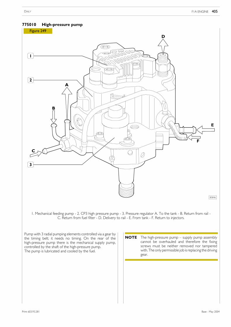
Electro-injectorNone of the couplings/unions/nuts on the injector body may be handled. It is neither necessary nor permitted todismantle the nozzle body or the electromagnet.If working on the high-pressure pipe, the hexagon on the injector side must be kept stationary with a wrench.Before working on pipes, make sure the injector is stationary in its seat on the cylinder head.When assembling/disassembling the injector drain, the retaining springmust not be removed from its seat in the injector:pushing the spring towards the engine and applying a vertical force on the connector frees the recirculation. Whenassembling, rest the recirculation connector in its seat and apply a vertical force while keeping the retaining springpressed in the direction of the engine. Fitting in has to be easy.
CP3 High-pressure pumpIf working on the high-pressure pipe, the hexagon on the pump side must be kept stationary with a wrench.Before working on the high-pressure pipe, make sure the pump is secured in its seat.
High-pressure pipesEach high-pressure pipe must be replaced after disassembly operations.The couplings must be tightened or loosened with the injectors, hydraulic accumulator (rail) and high-pressure pumpwell secured and taking care to keep the hexagon on the component side stationary, space permitting.
Hydraulic accumulator (rail) and accessoriesPressure sensor, as well as pressure relief valve (if present) can be successively mounted 5 times. Thereafter, they needto be replaced. They must be lubricated with a thin layer of oil before being mounted.Pressure relief valve, if present, must also be lubricated before being mounted and its gasket must compulsorily bereplaced.
Toothed timing drive beltIf the engine has run for a period equivalent to over 25,000 km, the toothed timing drive belt must be replaced witha fresh one, no matter what its state of wear, whenever it gets removed or any work is done on its automatic tightener.
F1A ENGINE 291DAILY
Base - May 2004Print 603.93.281
72446
F1A ENGINE DAILY292
Base - May 2004 Print 603.93.281
540110 ENGINE REMOVAL-REFITTING
75818
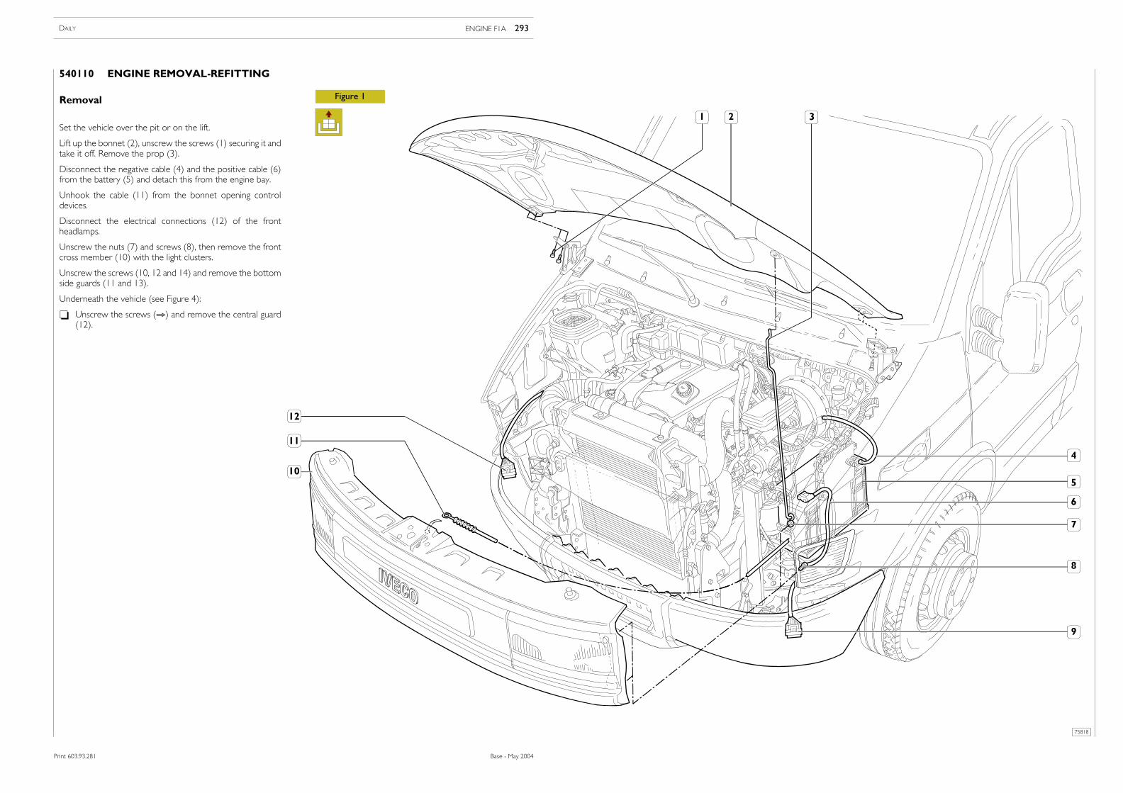
Figure 1Removal
Set the vehicle over the pit or on the lift.
Lift up the bonnet (2), unscrew the screws (1) securing it andtake it off. Remove the prop (3).
Disconnect the negative cable (4) and the positive cable (6)from the battery (5) and detach this from the engine bay.
Unhook the cable (11) from the bonnet opening controldevices.
Disconnect the electrical connections (12) of the frontheadlamps.
Unscrew the nuts (7) and screws (8), then remove the frontcross member (10) with the light clusters.
Unscrew the screws (10, 12 and 14) and remove the bottomside guards (11 and 13).
Underneath the vehicle (see Figure 4):
- Unscrew the screws (⇒) and remove the central guard(12).
ENGINE F1A 293DAILY
Print 603.93.281 Base - May 2004
Print 603.93.281
75817
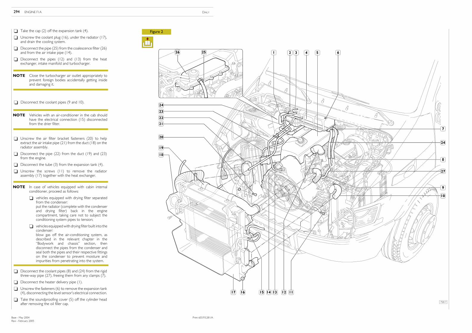
Figure 2- Take the cap (2) off the expansion tank (4).
- Unscrew the coolant plug (16), under the radiator (17),and drain the cooling system.
- Disconnect the pipe (25) from the coalescence filter (26)and from the air intake pipe (14).
- Disconnect the pipes (12) and (13) from the heatexchanger, intake manifold and turbocharger.
- Unscrew the air filter bracket fasteners (20) to helpextract the air intake pipe (21) from the duct (18) on theradiator assembly.
- Disconnect the pipe (22) from the duct (19) and (23)from the engine.
- Disconnect the tube (3) from the expansion tank (4).
- Unscrew the screws (11) to remove the radiatorassembly (17) together with the heat exchanger.
- Disconnect the coolant pipes (8) and (24) from the rigidthree-way pipe (27), freeing them from any clamps (7).
- Disconnect the heater delivery pipe (1).
- Unscrew the fasteners (6) to remove the expansion tank(4), disconnecting the level sensor’s electrical connection.
- Take the soundproofing cover (5) off the cylinder headafter removing the oil filler cap.
- Disconnect the coolant pipes (9 and 10).
Close the turbocharger air outlet appropriately toprevent foreign bodies accidentally getting insideand damaging it.
NOTE
Vehicles with an air-conditioner in the cab shouldhave the electrical connection (15) disconnectedfrom the drier filter.
NOTE
In case of vehicles equipped with cabin internalconditioner, proceed as follows:
- vehicles equipped with drying filter separatedfrom the condenser:put the radiator (complete with the condenserand drying filter) back in the enginecompartment, taking care not to subject theconditioning system pipes to tension;
- vehicles equippedwith drying filter built into thecondenser:blow gas off the air-conditioning system, asdescribed in the relevant chapter in the“Bodywork and chassis” section, thendisconnect the pipes from the condenser andseal both the pipes and their respective fittingson the condenser to prevent moisture andimpurities from penetrating into the system.
NOTE
Revi - February 2005
294 ENGINE F1A DAILY
Base - May 2004 Print 603.93.281/A
Print 603.93.281/A
75820
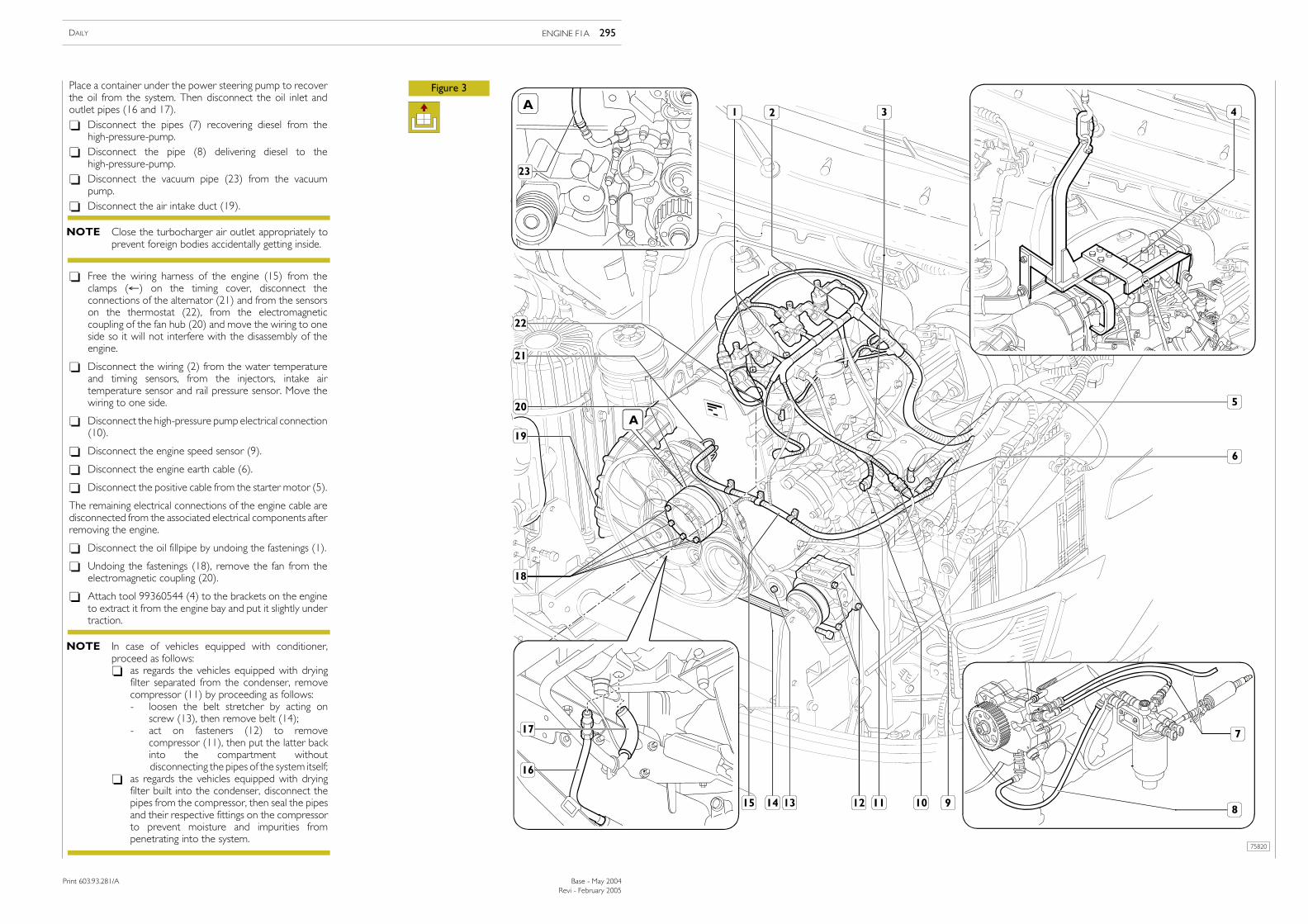
Figure 3Place a container under the power steering pump to recoverthe oil from the system. Then disconnect the oil inlet andoutlet pipes (16 and 17).- Disconnect the pipes (7) recovering diesel from the
high-pressure-pump.- Disconnect the pipe (8) delivering diesel to the
high-pressure-pump.- Disconnect the vacuum pipe (23) from the vacuum
pump.- Disconnect the air intake duct (19).
- Free the wiring harness of the engine (15) from theclamps (←) on the timing cover, disconnect theconnections of the alternator (21) and from the sensorson the thermostat (22), from the electromagneticcoupling of the fan hub (20) and move the wiring to oneside so it will not interfere with the disassembly of theengine.
- Disconnect the wiring (2) from the water temperatureand timing sensors, from the injectors, intake airtemperature sensor and rail pressure sensor. Move thewiring to one side.
- Disconnect the high-pressure pump electrical connection(10).
- Disconnect the engine speed sensor (9).
- Disconnect the engine earth cable (6).
- Disconnect the positive cable from the starter motor (5).
The remaining electrical connections of the engine cable aredisconnected from the associated electrical components afterremoving the engine.
- Disconnect the oil fillpipe by undoing the fastenings (1).
- Undoing the fastenings (18), remove the fan from theelectromagnetic coupling (20).
- Attach tool 99360544 (4) to the brackets on the engineto extract it from the engine bay and put it slightly undertraction.
Close the turbocharger air outlet appropriately toprevent foreign bodies accidentally getting inside.
NOTE
In case of vehicles equipped with conditioner,proceed as follows:- as regards the vehicles equipped with drying
filter separated from the condenser, removecompressor (11) by proceeding as follows:- loosen the belt stretcher by acting on
screw (13), then remove belt (14);- act on fasteners (12) to remove
compressor (11), then put the latter backinto the compartment withoutdisconnecting the pipes of the system itself;
- as regards the vehicles equipped with dryingfilter built into the condenser, disconnect thepipes from the compressor, then seal the pipesand their respective fittings on the compressorto prevent moisture and impurities frompenetrating into the system.
NOTE
Revi - February 2005
ENGINE F1A 295DAILY
Print 603.93.281/A Base - May 2004
Revi - February 2005
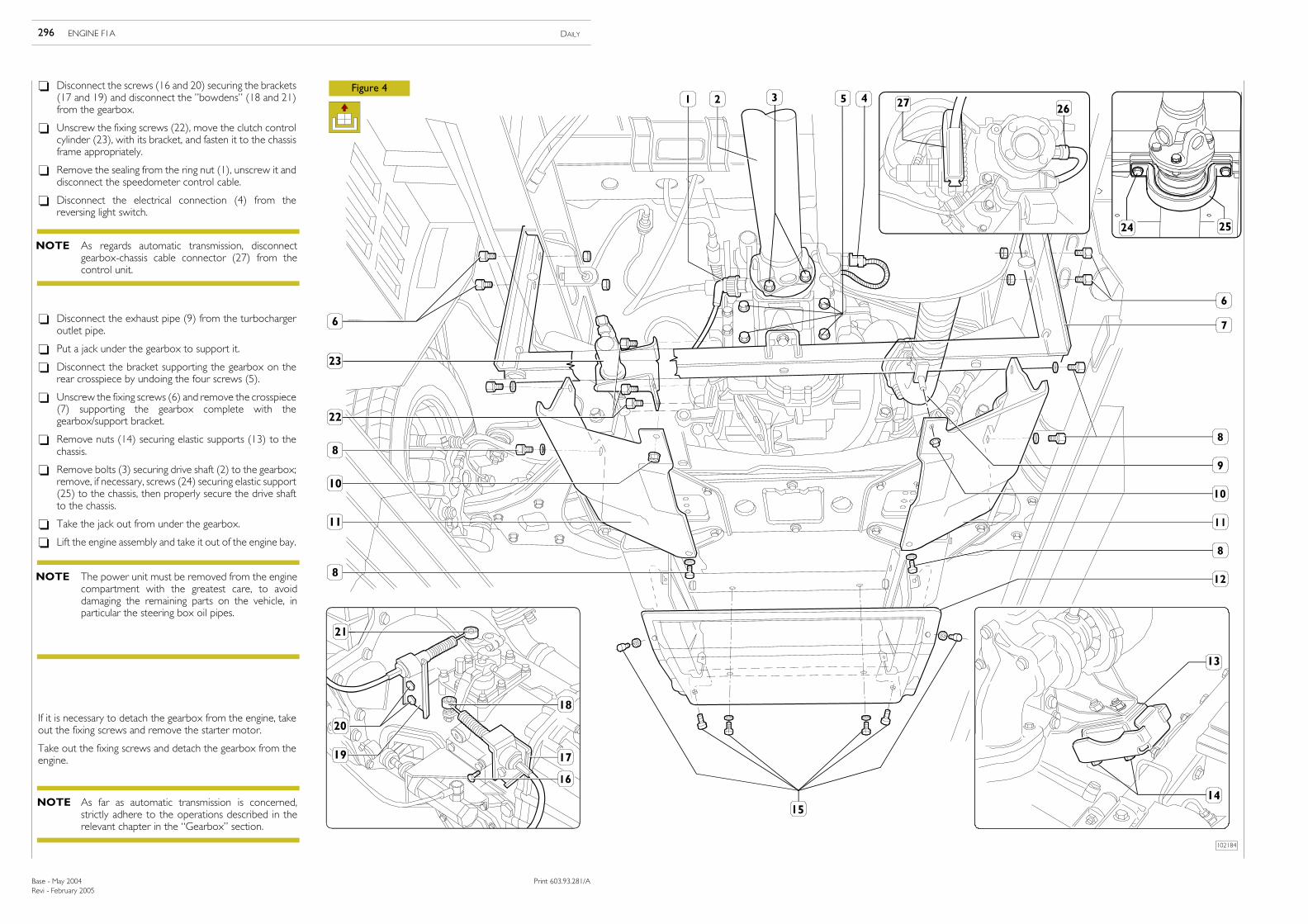
- Disconnect the screws (16 and 20) securing the brackets(17 and 19) and disconnect the ”bowdens” (18 and 21)from the gearbox.
- Unscrew the fixing screws (22), move the clutch controlcylinder (23), with its bracket, and fasten it to the chassisframe appropriately.
- Remove the sealing from the ring nut (1), unscrew it anddisconnect the speedometer control cable.
- Disconnect the electrical connection (4) from thereversing light switch.
Figure 4
If it is necessary to detach the gearbox from the engine, takeout the fixing screws and remove the starter motor.
Take out the fixing screws and detach the gearbox from theengine.
The power unit must be removed from the enginecompartment with the greatest care, to avoiddamaging the remaining parts on the vehicle, inparticular the steering box oil pipes.
NOTE
As far as automatic transmission is concerned,strictly adhere to the operations described in therelevant chapter in the “Gearbox” section.
NOTE
- Disconnect the exhaust pipe (9) from the turbochargeroutlet pipe.
- Put a jack under the gearbox to support it.
- Disconnect the bracket supporting the gearbox on therear crosspiece by undoing the four screws (5).
- Unscrew the fixing screws (6) and remove the crosspiece(7) supporting the gearbox complete with thegearbox/support bracket.
- Remove nuts (14) securing elastic supports (13) to thechassis.
- Remove bolts (3) securing drive shaft (2) to the gearbox;remove, if necessary, screws (24) securing elastic support(25) to the chassis, then properly secure the drive shaftto the chassis.
- Take the jack out from under the gearbox.
- Lift the engine assembly and take it out of the engine bay.
As regards automatic transmission, disconnectgearbox-chassis cable connector (27) from thecontrol unit.
NOTE
102184
296 ENGINE F1A DAILY
Base - May 2004 Print 603.93.281/A
- No water leaks from the connecting sleeves of theengine cooling and cab heating circuit pipes; tighten thecollars if necessary.
- No oil leaks from between the cover and cylinder head,oil sump and crankcase, oil filter and its seat, heatexchanger and crankcase or from between the variouspipes of the lubricating circuit.
- No fuel leaks from injection pump and injector lines.Tighten fittings if necessary.
- Check the indicator andwarning lights on the instrumentpanel and the devices disconnected on removing theengine all work properly.
Refitting
To refit the engine assembly, carry out the operationsdescribed for removal in reverse order, following theseinstructions:
- Before refitting the gearbox to the engine, it is necessaryto remove the pressure plate bearing from thediaphragm spring by opening out the retaining circlip.Fit the pressure plate bearing on the sleeve of the driveinput shaft cover, connecting it to the clutch releaselever. Spread the gearbox input shaft with Molikotemolybdenum disulphide grease.Engage a gear to let the main shaft turn, rotating thepropeller shaft connecting flange. Push the gearbox fullyin so that the pressure plate bearing couples with thediaphragm spring correctly.
- Pay special attention to the operations needed to installthe engine assembly in the engine bay.
- Check the conditions of the coolant pipes or sleeves andof the air ducts. Replace them if they show any sign ofdeterioration.
- Check the flexible mountings of the assemblies: engineand gearbox. Replace them if they show any sign ofdeterioration.
- Check that the exhaust pipe members have notdeteriorated and are not about to deteriorate. If this isso, replace them along with the flexible parts for securingthem.
- Tighten the screws or nuts to the required torque.
- Meticulously check the state of the vacuum pipe. It mustshow no sign of cracking, cutting, scoring or of beingcrushed. Replace it if there is any doubt at all about itssoundness. When mounting it, make sure the pipe doesnot come into contact with sharp metal parts or cornersor with any particularly hot parts. In addition, afterassembly, the pipe must have no bends or constrictions,its radius of curvature should be broad and it must besecured to the vacuum pump fitting with a suitableclamp.
- Make sure the quick-coupling fittings of the fuel pipes arethoroughly clean and, after connection to the relevanthigh-pressure pump unions or fuel filter mount, are fullyinserted and do not come loose.
- Fill the cooling system with coolant.
- Fill the hydraulic power steering circuit and bleed the airas described under the relevant heading.
- Check the level of oil in the engine and gearbox.
- Adjust the tension of the drive belt of the compressorfor the air-conditioner as described in �Replacing Belts�(if present).
Check the level of oil in the tank and top it up if necessary.Lift the vehicle at the front, start up the engine and let it idlefor some time.Check there is no oil leakage from the hydraulic circuit andcheck the level in the tank.Slowly turn the steering wheel in both directions of steeringso that the air in the hydraulic system comes out.Check the level of oil in the tank again and top up if necessary.
501430 Power steering system airbleed
Checks and tests
Start up the engine, leave it running just a little fasterthan idling speed and wait for the coolanttemperature to reach the value for opening thethermostat, then check that:
When positioning the engine in the engine bay,take special care not to damage the top pipe of thepower steering and the soundproof-heatproofcladding of the engine bay.Once positioned, meticulously check that the toppipe of the power steering is sound.Before using it again, check that the power steeringoil and coolant contain no impurities. If they do,filter with suitable mesh filters. For any topping up,refer to the REPLENISHING FLUIDS table in the�GENERAL� section.
NOTE
F1A ENGINE 297DAILY
Base - May 2004Print 603.93.281
75247
75502
75248
Figure 5
Figure 6
Figure 7
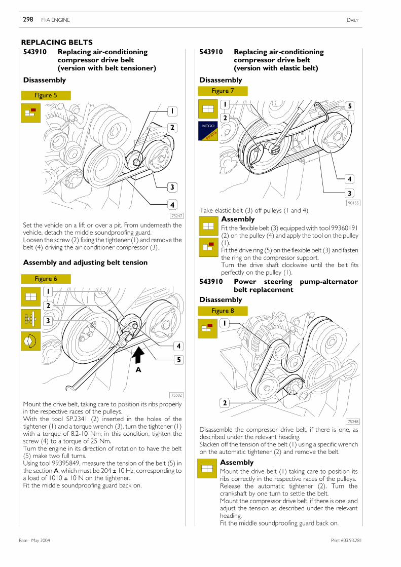
Set the vehicle on a lift or over a pit. From underneath thevehicle, detach the middle soundproofing guard.Loosen the screw (2) fixing the tightener (1) and remove thebelt (4) driving the air-conditioner compressor (3).
Assembly and adjusting belt tension
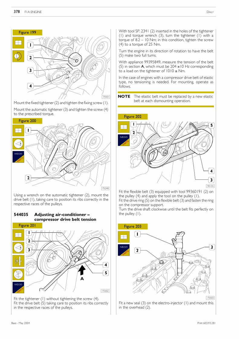
Mount the drive belt, taking care to position its ribs properlyin the respective races of the pulleys.With the tool SP.2341 (2) inserted in the holes of thetightener (1) and a torque wrench (3), turn the tightener (1)with a torque of 8.2-10 Nm; in this condition, tighten thescrew (4) to a torque of 25 Nm.Turn the engine in its direction of rotation to have the belt(5) make two full turns.Using tool 99395849, measure the tension of the belt (5) inthe section A, which must be 204 ± 10 Hz, corresponding toa load of 1010 ± 10 N on the tightener.Fit the middle soundproofing guard back on.
543910 Replacing air-conditioningcompressor drive belt(version with belt tensioner)
Disassembly
Disassemble the compressor drive belt, if there is one, asdescribed under the relevant heading.Slacken off the tension of the belt (1) using a specific wrenchon the automatic tightener (2) and remove the belt.
543910 Power steering pump-alternatorbelt replacement
Disassembly
AssemblyMount the drive belt (1) taking care to position itsribs correctly in the respective races of the pulleys.Release the automatic tightener (2). Turn thecrankshaft by one turn to settle the belt.Mount the compressor drive belt, if there is one, andadjust the tension as described under the relevantheading.Fit the middle soundproofing guard back on.
543910 Replacing air-conditioningcompressor drive belt(version with elastic belt)
Disassembly
Figure 8
90155
Take elastic belt (3) off pulleys (1 and 4).AssemblyFit the flexible belt (3) equipped with tool 99360191(2) on the pulley (4) and apply the tool on the pulley(1).Fit the drive ring (5) on the flexible belt (3) and fastenthe ring on the compressor support.Turn the drive shaft clockwise until the belt fitsperfectly on the pulley (1).
F1A ENGINE DAILY298
Base - May 2004 Print 603.93.281
REPLACING BELTS
Figure 9
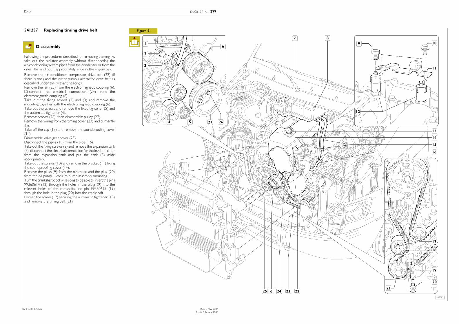
Remove the air-conditioner compressor drive belt (22) (ifthere is one) and the water pump / alternator drive belt asdescribed under the relevant headings.Remove the fan (25) from the electromagnetic coupling (6).Disconnect the electrical connection (24) from theelectromagnetic coupling (6).Take out the fixing screws (2) and (3) and remove themounting together with the electromagnetic coupling (6).Take out the screws and remove the fixed tightener (5) andthe automatic tightener (4).Remove screws (26), then disassemble pulley (27).Remove the wiring from the timing cover (23) and dismantlethis.Take off the cap (13) and remove the soundproofing cover(14).Disassemble valve gear cover (23).Disconnect the pipes (15) from the pipe (16).Take out the fixing screws (8) and remove the expansion tank(7); disconnect the electrical connection for the level indicatorfrom the expansion tank and put the tank (8) asideappropriately.Take out the screws (10) and remove the bracket (11) fixingthe soundproofing cover (14).Remove the plugs (9) from the overhead and the plug (20)from the oil pump — vacuum pump assembly mounting.Turn the crankshaft clockwise so as to be able to insert the pins99360614 (12) through the holes in the plugs (9) into therelevant holes of the camshafts and pin 99360615 (19)through the hole in the plug (20) into the crankshaft.Loosen the screw (17) securing the automatic tightener (18)and remove the timing belt (21).
541257 Replacing timing drive belt
Following the procedures described for removing the engine,take out the radiator assembly without disconnecting theair-conditioning system pipes from the condenser or from thedrier filter and put it appropriately aside in the engine bay.
Disassembly
102093
Revi - February 2005
ENGINE F1A 299DAILY
Print 603.93.281/A Base - May 2004
Print 603.93.281/A
85844
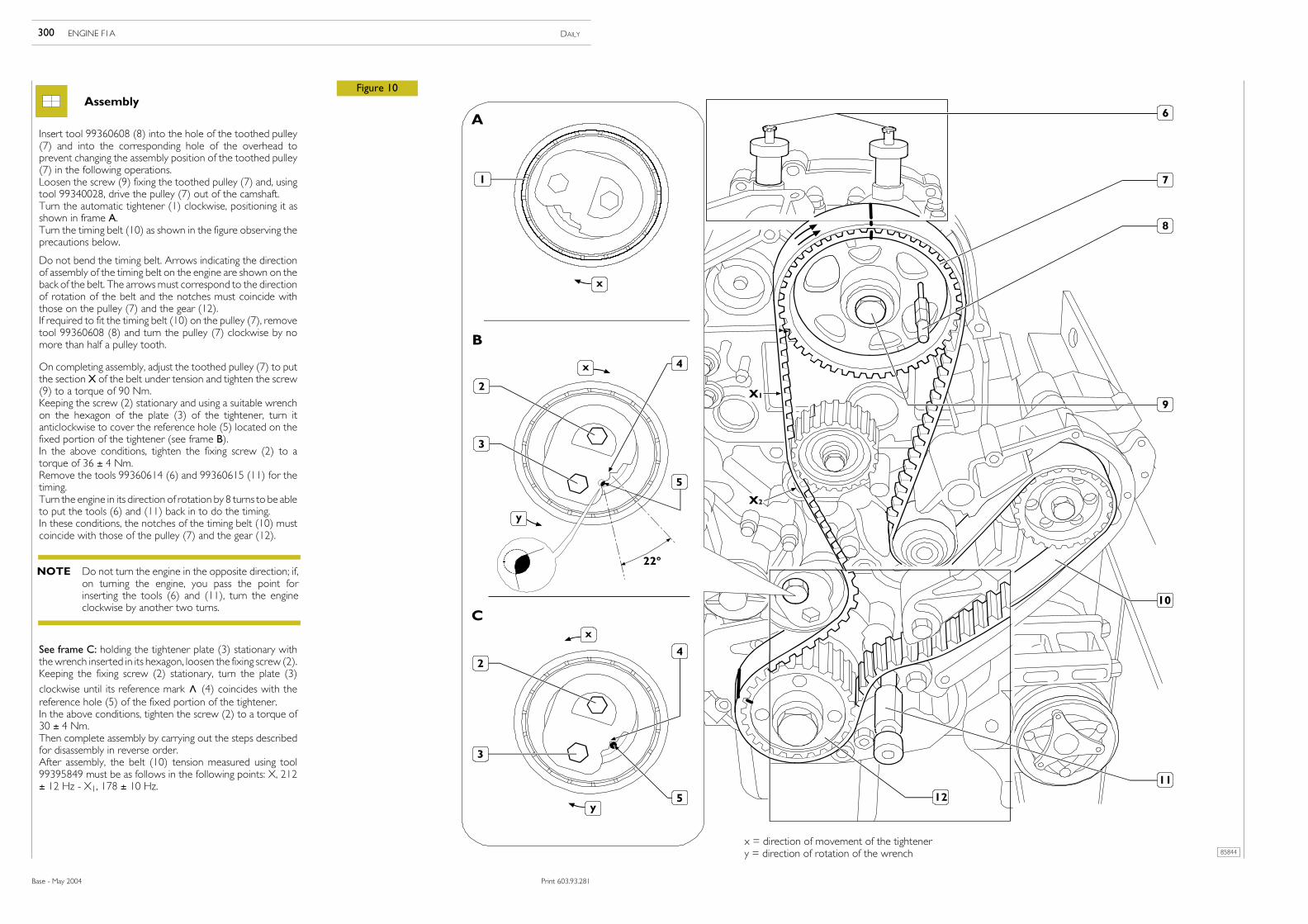
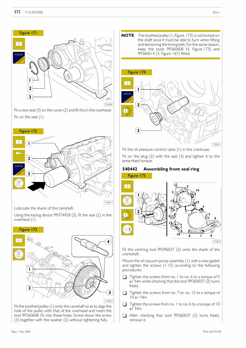
Figure 10Assembly
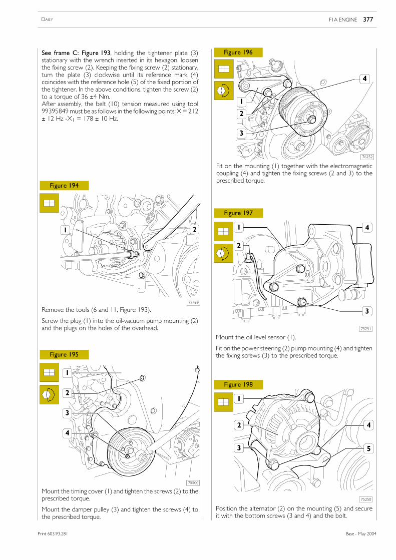
Insert tool 99360608 (8) into the hole of the toothed pulley(7) and into the corresponding hole of the overhead toprevent changing the assembly position of the toothed pulley(7) in the following operations.Loosen the screw (9) fixing the toothed pulley (7) and, usingtool 99340028, drive the pulley (7) out of the camshaft.Turn the automatic tightener (1) clockwise, positioning it asshown in frame A.Turn the timing belt (10) as shown in the figure observing theprecautions below.
Do not bend the timing belt. Arrows indicating the directionof assembly of the timing belt on the engine are shown on theback of the belt. The arrowsmust correspond to the directionof rotation of the belt and the notches must coincide withthose on the pulley (7) and the gear (12).If required to fit the timing belt (10) on the pulley (7), removetool 99360608 (8) and turn the pulley (7) clockwise by nomore than half a pulley tooth.
See frame C: holding the tightener plate (3) stationary withthewrench inserted in its hexagon, loosen the fixing screw (2).Keeping the fixing screw (2) stationary, turn the plate (3)
clockwise until its reference mark ∧ (4) coincides with thereference hole (5) of the fixed portion of the tightener.In the above conditions, tighten the screw (2) to a torque of30 ± 4 Nm.Then complete assembly by carrying out the steps describedfor disassembly in reverse order.After assembly, the belt (10) tension measured using tool99395849 must be as follows in the following points: X, 212± 12 Hz - X1, 178 ± 10 Hz.
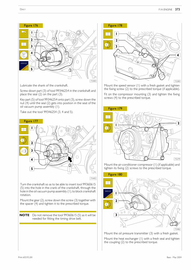
On completing assembly, adjust the toothed pulley (7) to putthe section X of the belt under tension and tighten the screw(9) to a torque of 90 Nm.Keeping the screw (2) stationary and using a suitable wrenchon the hexagon of the plate (3) of the tightener, turn itanticlockwise to cover the reference hole (5) located on thefixed portion of the tightener (see frame B).In the above conditions, tighten the fixing screw (2) to atorque of 36 ± 4 Nm.Remove the tools 99360614 (6) and 99360615 (11) for thetiming.Turn the engine in its direction of rotation by 8 turns to be ableto put the tools (6) and (11) back in to do the timing.In these conditions, the notches of the timing belt (10) mustcoincide with those of the pulley (7) and the gear (12).
x = direction of movement of the tightenery = direction of rotation of the wrench
Do not turn the engine in the opposite direction; if,on turning the engine, you pass the point forinserting the tools (6) and (11), turn the engineclockwise by another two turns.
NOTE
300 ENGINE F1A DAILY
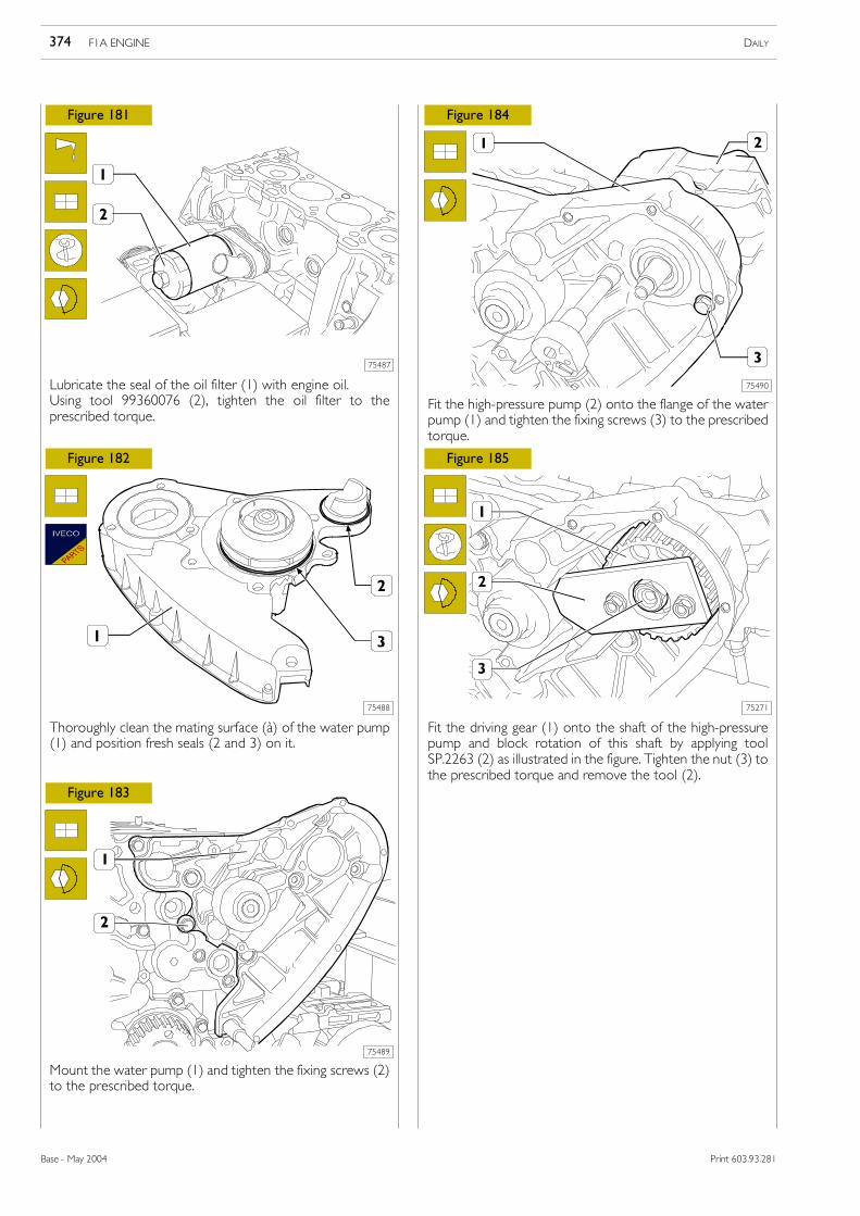
Base - May 2004 Print 603.93.281
Print 603.93.281
75564
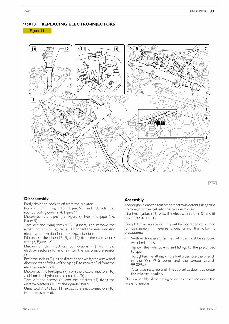
Figure 11
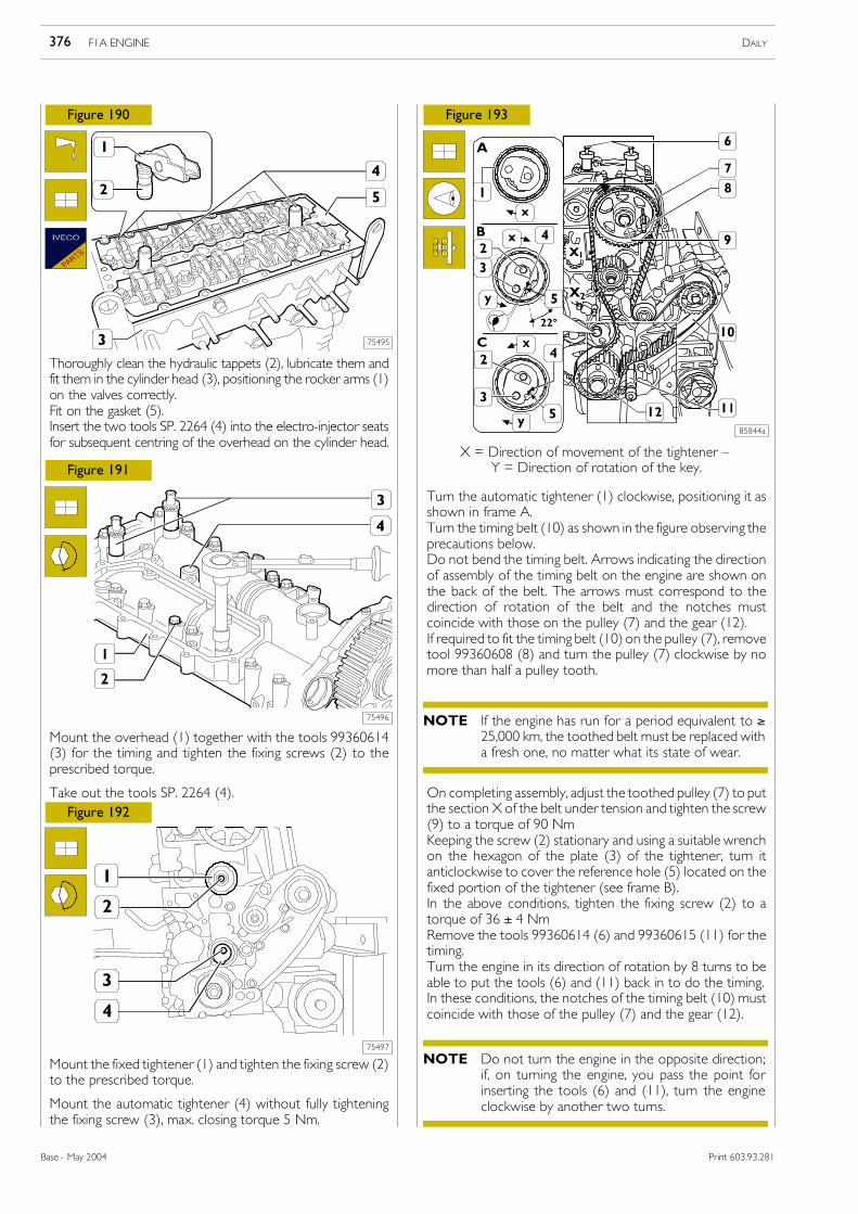
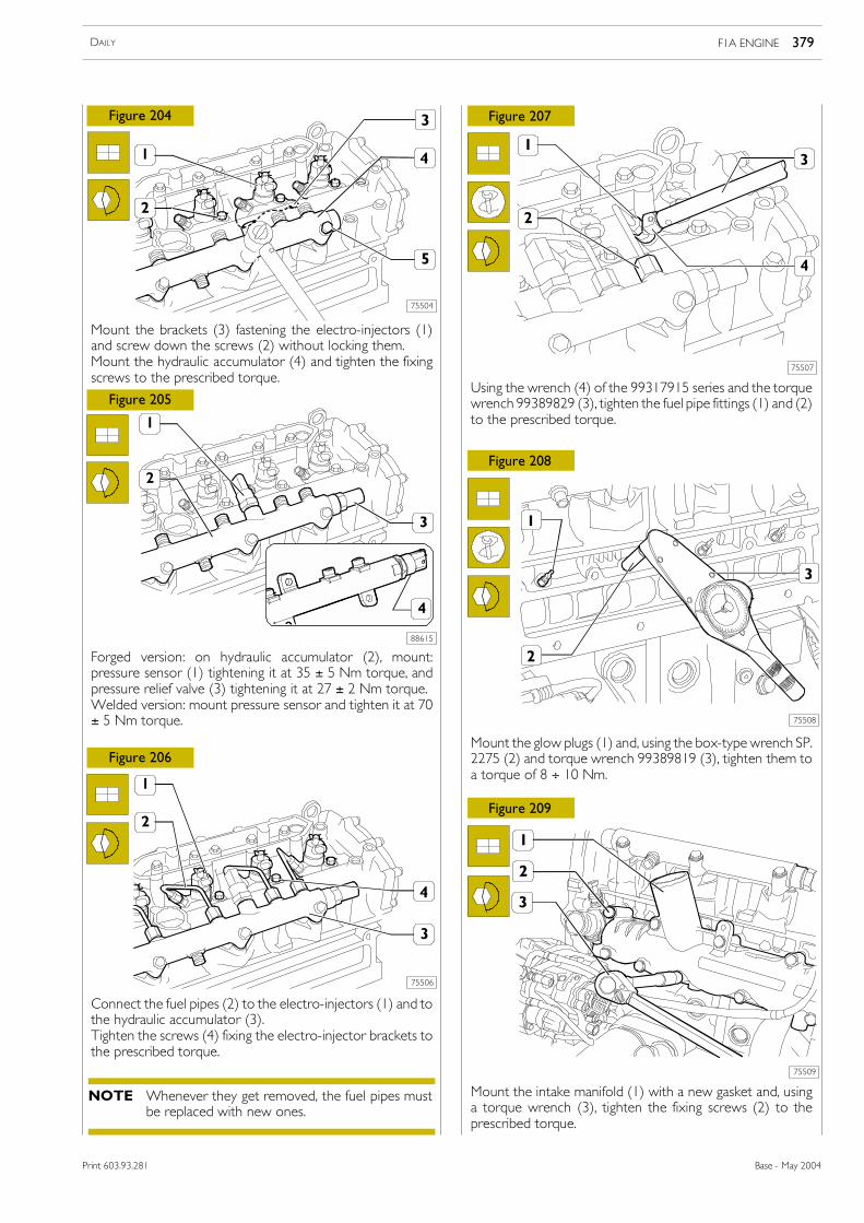
AssemblyThoroughly clean the seat of the electro-injectors, taking careno foreign bodies get into the cylinder barrels.Fit a fresh gasket (12) onto the electro-injector (10) and fitthis in the overhead.
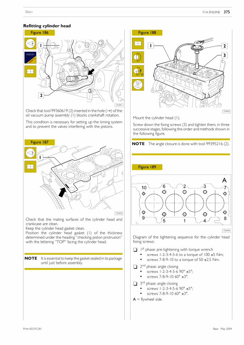
Complete assembly by carrying out the operations describedfor disassembly in reverse order, taking the followingprecautions:
- With each disassembly, the fuel pipes must be replacedwith fresh ones.
- Tighten the nuts, screws and fittings to the prescribedtorque.
- To tighten the fittings of the fuel pipes, use the wrenchin the 99317915 series and the torque wrench99389829.
- After assembly, replenish the coolant as described underthe relevant heading.
Check assembly of the timing sensor as described under therelevant heading.
DisassemblyPartly drain the coolant off from the radiator.Remove the plug (13, Figure 9) and detach thesoundproofing cover (14, Figure 9).Disconnect the pipes (15, Figure 9) from the pipe (16,Figure 9).Take out the fixing screws (8, Figure 9) and remove theexpansion tank (7, Figure 9). Disconnect the level indicatorelectrical connection from the expansion tank.Disconnect the pipe (17, Figure 12) from the coalescencefilter (2, Figure 12).Disconnect the electrical connections (1) from theelectro-injectors (10) and (2) from the fuel pressure sensor(8).Press the springs (3) in the direction shown by the arrow anddisconnect the fittings of the pipe (4) to recover fuel from theelectro-injectors (10).Disconnect the fuel pipes (7) from the electro-injectors (10)and from the hydraulic accumulator (9).Take out the screws (6) and the brackets (5) fixing theelectro-injectors (10) to the cylinder head.Using tool 99342153 (11) extract the electro-injectors (10)from the overhead.
F1A ENGINE 301DAILY
Base - May 2004Print 603.93.281
775010 REPLACING ELECTRO-INJECTORS
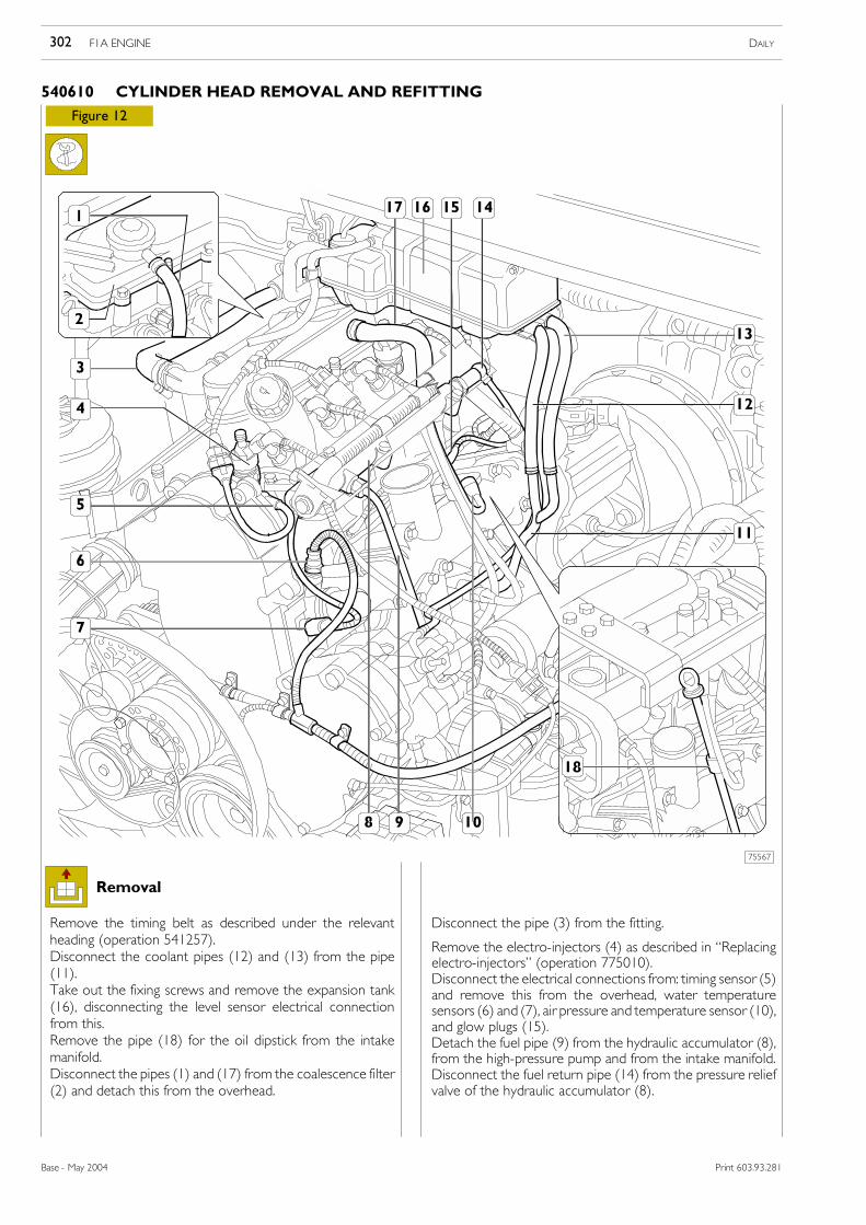
Figure 12
Remove the timing belt as described under the relevantheading (operation 541257).Disconnect the coolant pipes (12) and (13) from the pipe(11).Take out the fixing screws and remove the expansion tank(16), disconnecting the level sensor electrical connectionfrom this.Remove the pipe (18) for the oil dipstick from the intakemanifold.Disconnect the pipes (1) and (17) from the coalescence filter(2) and detach this from the overhead.
Disconnect the pipe (3) from the fitting.
Remove the electro-injectors (4) as described in �Replacingelectro-injectors� (operation 775010).Disconnect the electrical connections from: timing sensor (5)and remove this from the overhead, water temperaturesensors (6) and (7), air pressure and temperature sensor (10),and glow plugs (15).Detach the fuel pipe (9) from the hydraulic accumulator (8),from the high-pressure pump and from the intake manifold.Disconnect the fuel return pipe (14) from the pressure reliefvalve of the hydraulic accumulator (8).
75567
Removal
F1A ENGINE DAILY302
Base - May 2004 Print 603.93.281
540610 CYLINDER HEAD REMOVAL AND REFITTING
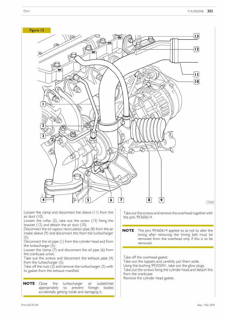
Take off the overhead gasket.Take out the tappets and carefully put them aside.Using the bushing 99355041, take out the glow plugs.Take out the screws fixing the cylinder head and detach thisfrom the crankcase.Remove the cylinder head gasket.
75568
Figure 13
Loosen the clamp and disconnect the sleeve (11) from theair duct (10).Loosen the collar (2), take out the screw (13) fixing thebracket (12) and detach the air duct (10).Disconnect the oil vapour recirculation pipe (8) from the airintake sleeve (9) and disconnect this from the turbocharger(5).Disconnect the oil pipe (1) from the cylinder head and fromthe turbocharger (5).Loosen the clamp (7) and disconnect the oil pipe (6) fromthe crankcase union.Take out the screws and disconnect the exhaust pipe (4)from the turbocharger (5).Take off the nuts (3) and remove the turbocharger (5) withits gasket from the exhaust manifold.
Take out the screws and remove the overhead together withthe pins 99360614.
Close the turbocharger air outlet/inletappropriately to prevent foreign bodiesaccidentally getting inside and damaging it.
NOTE
The pins 99360614 applied so as not to alter thetiming after removing the timing belt must beremoved from the overhead only if this is to beremoved.
NOTE
F1A ENGINE 303DAILY
Base - May 2004Print 603.93.281
Refitting
Refitting requires carrying out the operations for removal inreverse order, while taking the following precautions:Check that the timing tools:
- 99360614 (6, Figure 10) and 99360608 (8, Figure 10)are inserted in the overhead;
- 99360615 (11, Figure 10) is inserted in the crankcase asdescribed in �Replacing timing belt.�
Check that the mating surfaces of the cylinder head andcrankcase are clean.Keep the cylinder head gasket clean.Position the cylinder head gasket with the lettering �TOP�facing the cylinder head.
Figure 14
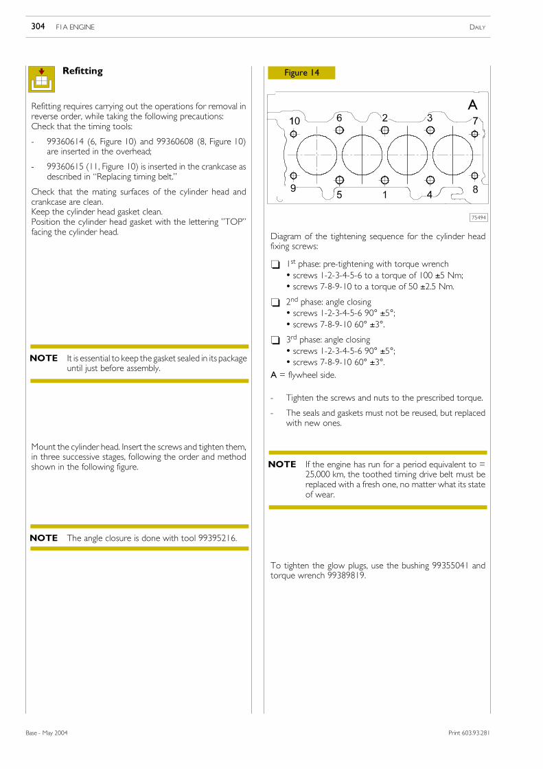
Diagram of the tightening sequence for the cylinder headfixing screws:
- 1st phase: pre-tightening with torque wrench• screws 1-2-3-4-5-6 to a torque of 100 ±5 Nm;• screws 7-8-9-10 to a torque of 50 ±2.5 Nm.
- Tighten the screws and nuts to the prescribed torque.
- The seals and gaskets must not be reused, but replacedwith new ones.
75494
Mount the cylinder head. Insert the screws and tighten them,in three successive stages, following the order and methodshown in the following figure.
To tighten the glow plugs, use the bushing 99355041 andtorque wrench 99389819.
A
It is essential to keep the gasket sealed in its packageuntil just before assembly.
NOTE
The angle closure is done with tool 99395216.NOTE
If the engine has run for a period equivalent to =25,000 km, the toothed timing drive belt must bereplaced with a fresh one, no matter what its stateof wear.
NOTE
F1A ENGINE DAILY304
Base - May 2004 Print 603.93.281
75271
75272
75273
75569
Figure 15
Figure 16
Figure 17
Figure 18
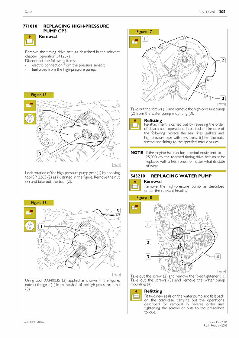
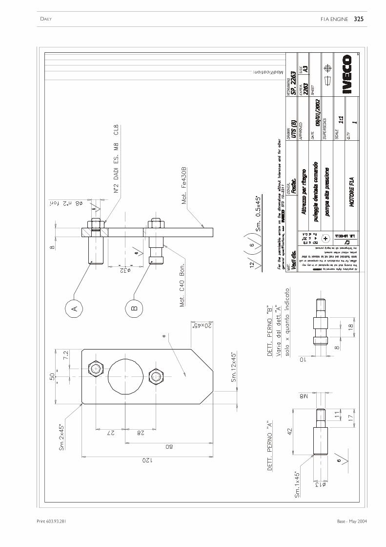
Lock rotation of the high-pressure pump gear (1) by applyingtool SP. 2263 (2) as illustrated in the figure. Remove the nut(3) and take out the tool (2).
Using tool 99340035 (2) applied as shown in the figure,extract the gear (1) from the shaft of the high-pressure pump(3).
Take out the screws (1) and remove the high-pressure pump(2) from the water pump mounting (3).
Take out the screw (2) and remove the fixed tightener (1).Take out the screws (3) and remove the water pumpmounting (4).
Removal
RefittingRe-attachment is carried out by reversing the orderof detachment operations. In particular, take care ofthe following: replace the seal rings, gaskets andhigh-pressure pipe with new parts; tighten the nuts,screws and fittings to the specified torque values.
543210 REPLACINGWATER PUMP
Refitting
If the engine has run for a period equivalent to =25,000 km, the toothed timing drive belt must bereplaced with a fresh one, no matter what its stateof wear.
NOTE
Remove the timing drive belt, as described in the relevantchapter (operation 541257).Disconnect the following items:- electric connection from the pressure sensor;- fuel pipes from the high-pressure pump.
Fit two new seals on the water pump and fit it backon the crankcase, carrying out the operationsdescribed for removal in reverse order andtightening the screws or nuts to the prescribedtorque.
RemovalRemove the high-pressure pump as describedunder the relevant heading.
Revi - February 2005
F1A ENGINE 305DAILY
Print 603.93.281/A Base - May 2004
Print 603.43.351Print 603.93.281/A
771010 REPLACING HIGH-PRESSUREPUMP CP3
Figure 19
75570
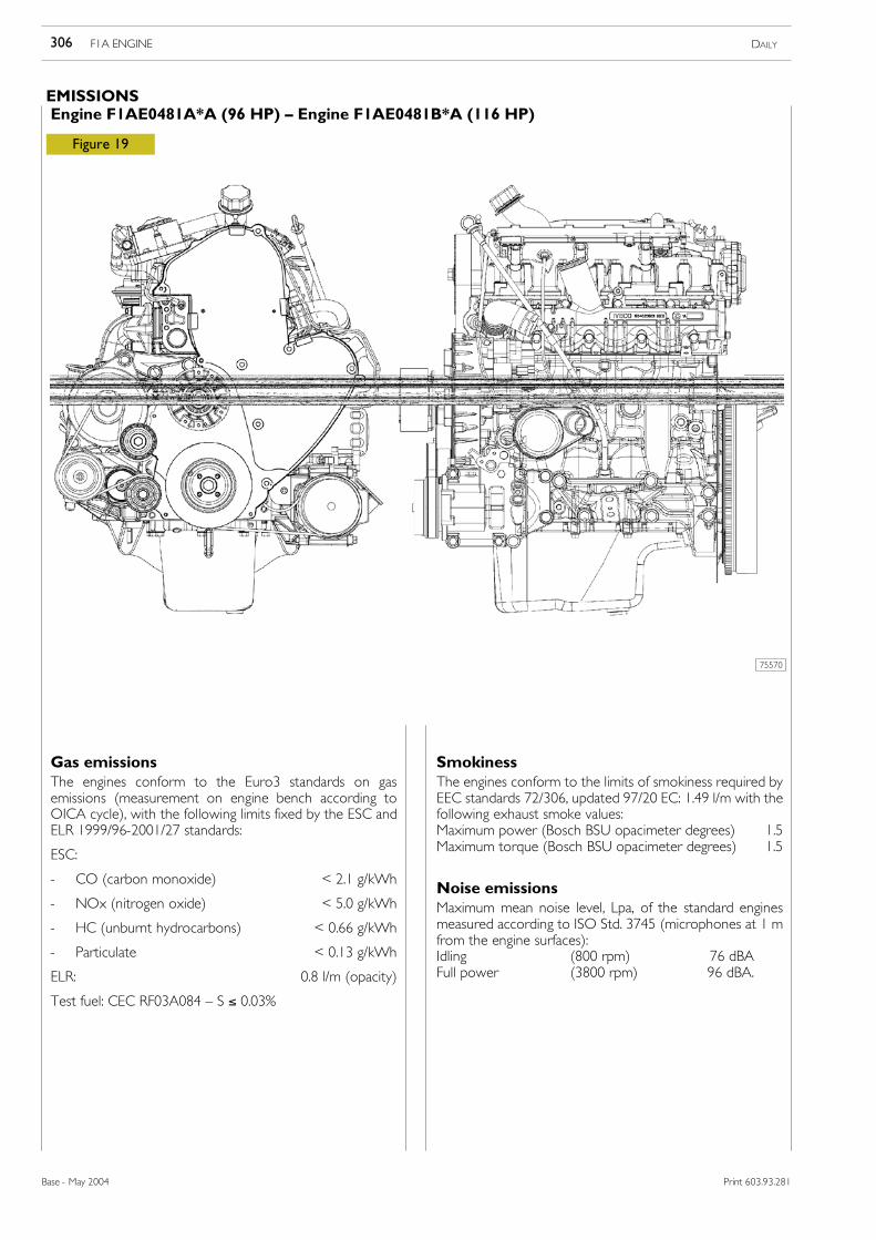
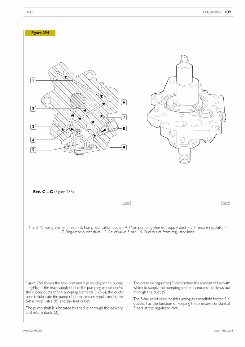
Gas emissionsThe engines conform to the Euro3 standards on gasemissions (measurement on engine bench according toOICA cycle), with the following limits fixed by the ESC andELR 1999/96-2001/27 standards:
ESC:
- CO (carbon monoxide) < 2.1 g/kWh
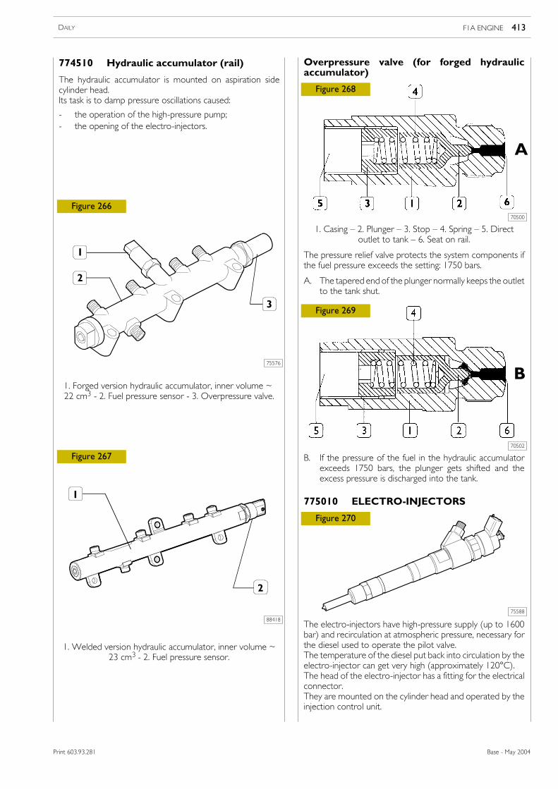
- NOx (nitrogen oxide) < 5.0 g/kWh
- HC (unburnt hydrocarbons) < 0.66 g/kWh
- Particulate < 0.13 g/kWh
ELR: 0.8 l/m (opacity)
Test fuel: CEC RF03A084 — S ≤ 0.03%
SmokinessThe engines conform to the limits of smokiness required byEEC standards 72/306, updated 97/20 EC: 1.49 l/m with thefollowing exhaust smoke values:Maximum power (Bosch BSU opacimeter degrees) 1.5Maximum torque (Bosch BSU opacimeter degrees) 1.5
Noise emissionsMaximum mean noise level, Lpa, of the standard enginesmeasured according to ISO Std. 3745 (microphones at 1 mfrom the engine surfaces):Idling (800 rpm) 76 dBAFull power (3800 rpm) 96 dBA.
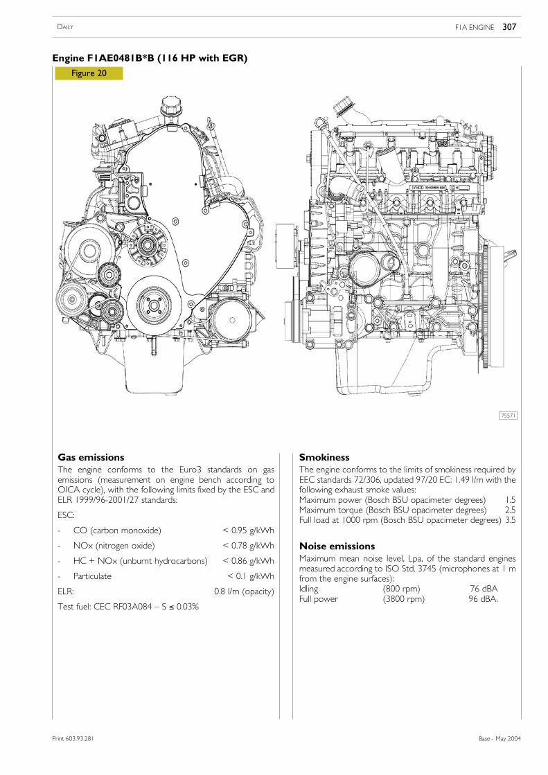
Gas emissionsThe engine conforms to the Euro3 standards on gasemissions (measurement on engine bench according toOICA cycle), with the following limits fixed by the ESC andELR 1999/96-2001/27 standards:
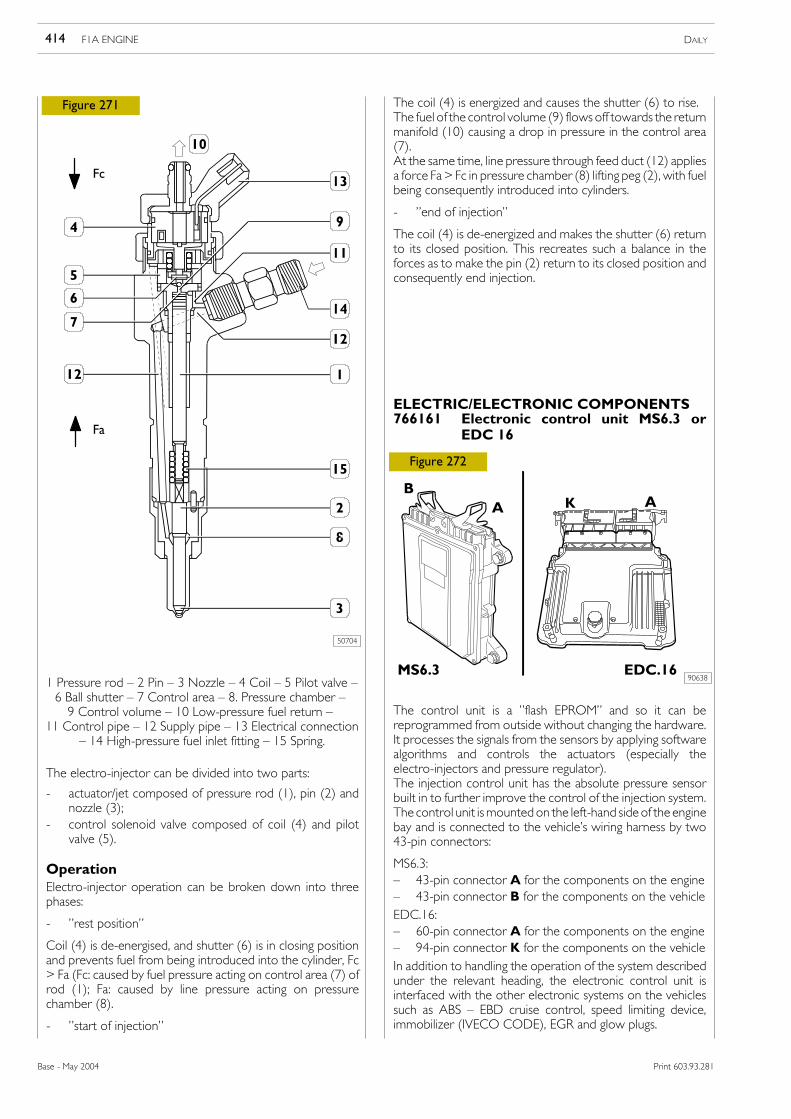
ESC:
- CO (carbon monoxide) < 0.95 g/kWh
- NOx (nitrogen oxide) < 0.78 g/kWh
- HC + NOx (unburnt hydrocarbons) < 0.86 g/kWh
- Particulate < 0.1 g/kWh
ELR: 0.8 l/m (opacity)
Test fuel: CEC RF03A084 — S ≤ 0.03%
SmokinessThe engine conforms to the limits of smokiness required byEEC standards 72/306, updated 97/20 EC: 1.49 l/m with thefollowing exhaust smoke values:Maximum power (Bosch BSU opacimeter degrees) 1.5Maximum torque (Bosch BSU opacimeter degrees) 2.5Full load at 1000 rpm (Bosch BSU opacimeter degrees) 3.5
Noise emissionsMaximum mean noise level, Lpa, of the standard enginesmeasured according to ISO Std. 3745 (microphones at 1 mfrom the engine surfaces):Idling (800 rpm) 76 dBAFull power (3800 rpm) 96 dBA.
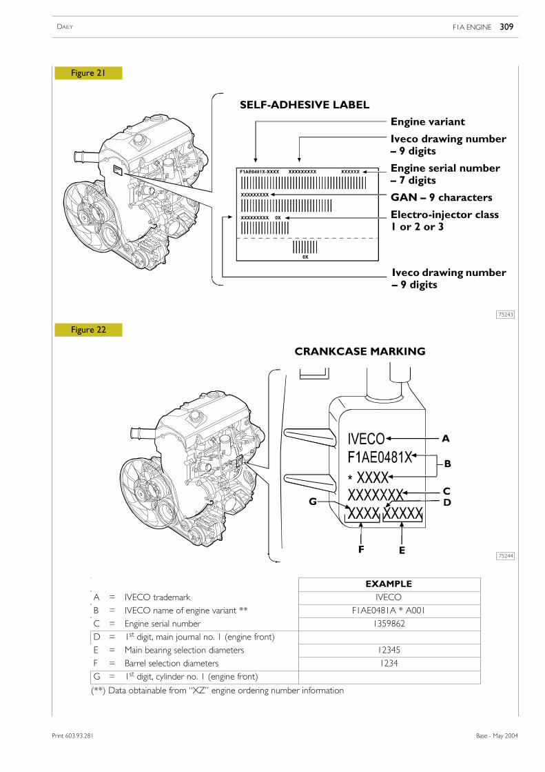
B = IVECO name of engine variant ** F1AE0481A * A001
C = Engine serial number 1359862
D = 1st digit, main journal no. 1 (engine front)
E = Main bearing selection diameters 12345
F = Barrel selection diameters 1234
G = 1st digit, cylinder no. 1 (engine front)
(**) Data obtainable from “XZ” engine ordering number information
Revi - February 2005
310 F1A ENGINE DAILY
Base - May 2004 Print 603.93.281/A
Print 603.93.281/A
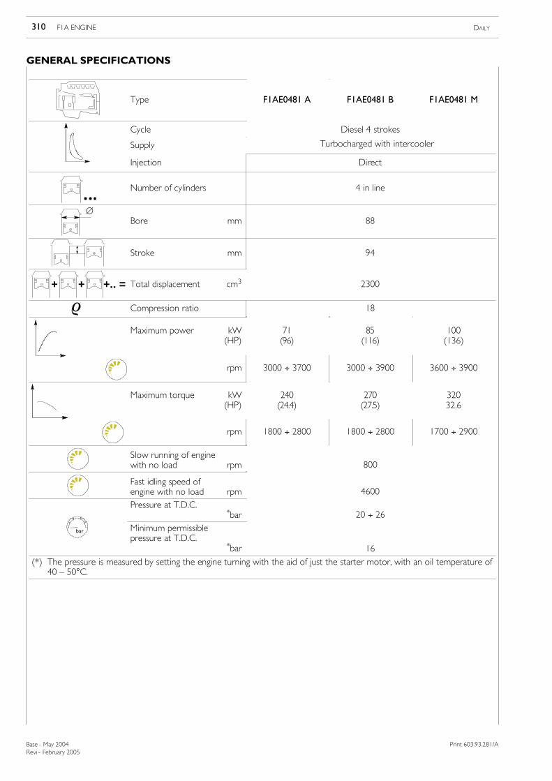
GENERAL SPECIFICATIONS
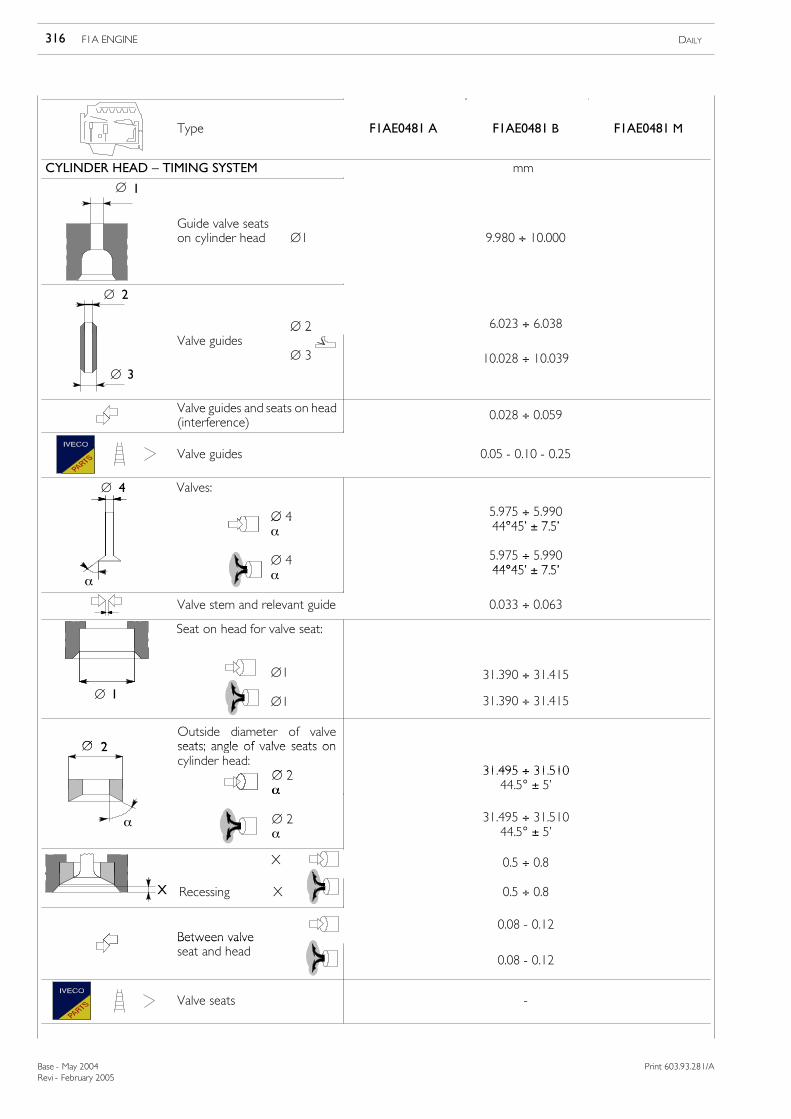
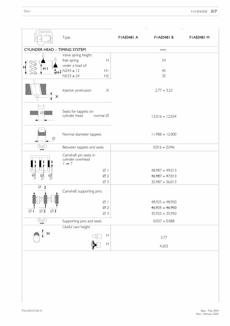
Type F1AE0481 A F1AE0481 B F1AE0481 M
Cycle Diesel 4 strokes
Supply Turbocharged with intercooler
Injection Direct
Number of cylinders 4 in line
∅Bore mm 88
Stroke mm 94
+ + +.. = Total displacement cm3 2300
ρ Compression ratio 18
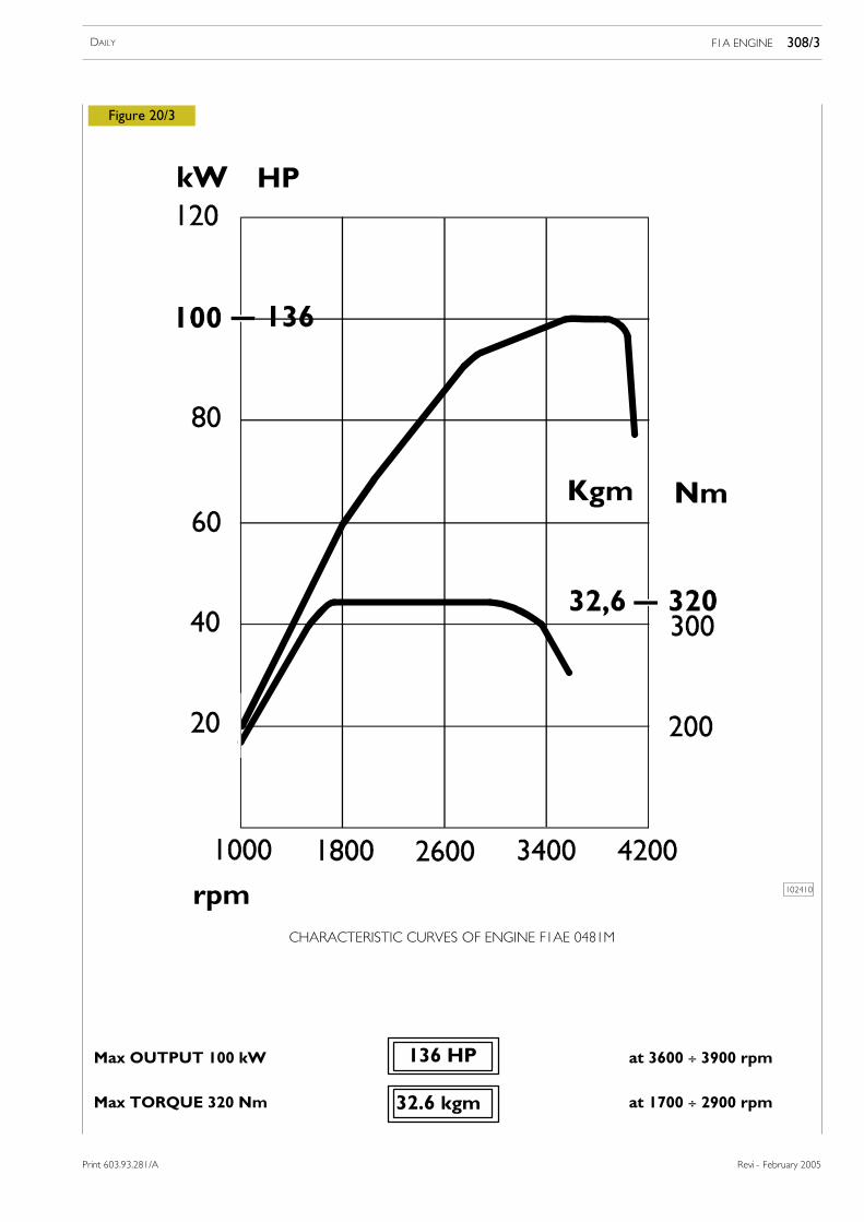
Maximum power kW(HP)
71(96)
85(116)
100(136)
rpm 3000 ÷ 3700 3000 ÷ 3900 3600 ÷ 3900
Maximum torque kW(HP)
240(24.4)
270(27.5)
32032.6
rpm 1800 ÷ 2800 1800 ÷ 2800 1700 ÷ 2900
Slow running of enginewith no load rpm 800
Fast idling speed ofengine with no load rpm 4600
Pressure at T.D.C.*bar 20 ÷ 26
bar Minimum permissiblepressure at T.D.C.
*bar 16
(*) The pressure is measured by setting the engine turning with the aid of just the starter motor, with an oil temperature of40 — 50°C.
Revi - February 2005
F1A ENGINE 311DAILY
Print 603.93.281/A Base - May 2004
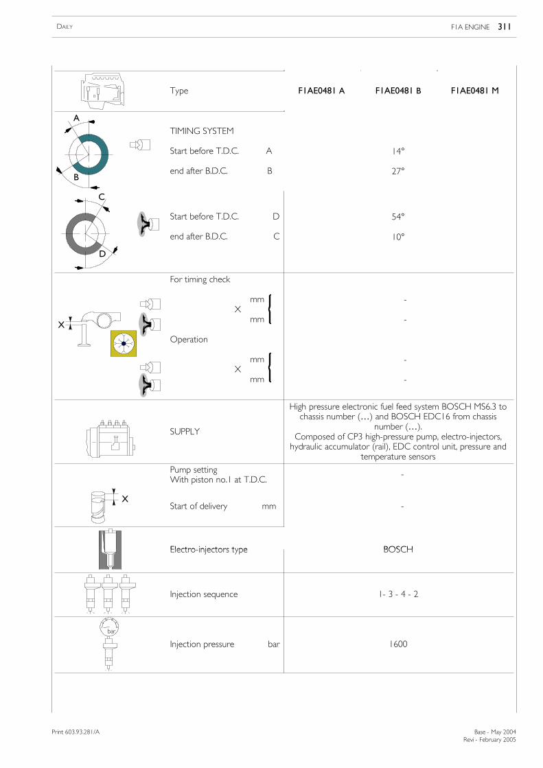
Type F1AE0481 A F1AE0481 B F1AE0481 M
A
B
TIMING SYSTEM
Start before T.D.C. A
end after B.D.C. B
14°
27°
C
D
Start before T.D.C. D
end after B.D.C. C
54°
10°
X
For timing check
mmX
mm
Operation
mmX
mm
-
-
-
-
SUPPLY
High pressure electronic fuel feed system BOSCH MS6.3 tochassis number (…) and BOSCH EDC16 from chassis
number (…).Composed of CP3 high-pressure pump, electro-injectors,hydraulic accumulator (rail), EDC control unit, pressure and
temperature sensors
Pump settingWith piston no.1 at T.D.C.
-
XStart of delivery mm -
Electro injectors type BOSCHElectro-injectors type BOSCH
Injection sequence 1- 3 - 4 - 2
bar
Injection pressure bar 1600
Revi - February 2005
312 F1A ENGINE DAILY
Base - May 2004 Print 603.93.281/A
Type F1AE0481 A F1AE0481 B F1AE0481 M
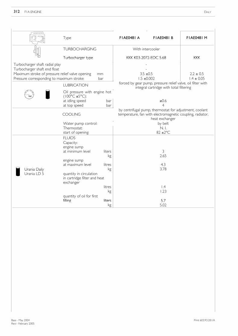
TURBOCHARGING With intercooler
Turbocharger type KKK K03 2072 EDC 5 68 KKKTurbocharger type KKK K03-2072-EDC 5.68 KKK
Turbocharger shaft radial play -Turbocharger shaft end float -Maximum stroke of pressure relief valve opening mm 3.5 ±0.5 2.2 ± 0.5Pressure corresponding to maximum stroke: bar 1.5 ±0.002 1.4 ± 0.05
LUBRICATION forced by gear pump, pressure relief valve, oil filter withintegral cartridge with total filtering
bar
Oil pressure with engine hot(100°C ±5°C):at idling speed bar ≥0.6at top speed bar 4
COOLINGby centrifugal pump, thermostat for adjustment, coolanttemperature, fan with electromagnetic coupling, radiator,
heat exchangerWater pump control: by beltThermostat:start of opening:
N. I.82 ±2ºC
FLUIDSCapacity:engine sumpat minimum level liters
kg32.65
Urania Daily
engine sumpat maximum level litres
kg4.33.78Urania Daily
Urania LD 5 quantity in circulationin cartridge filter and heatexchanger
litreskg
1.41.23
quantity of oil for firstfilling liters 5 7filling liters
kg5.75.02
Revi - February 2005
F1A ENGINE 313DAILY
Print 603.93.281/A Base - May 2004
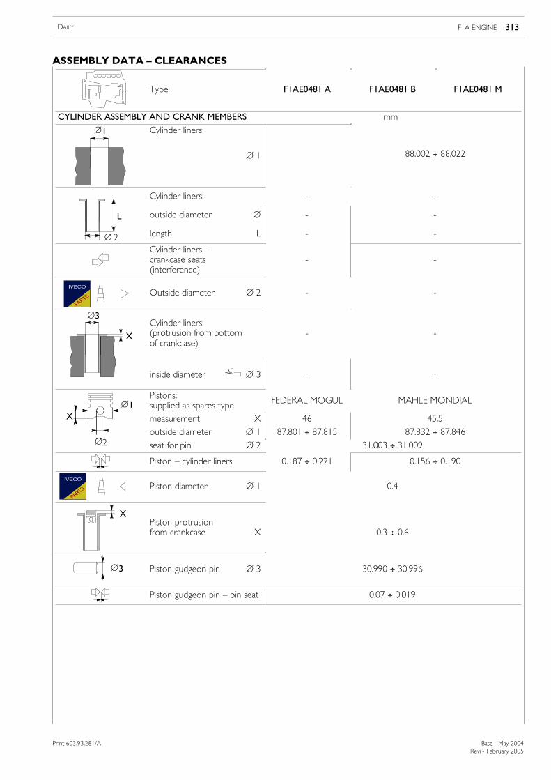
ASSEMBLY DATA — CLEARANCES
Type F1AE0481 A F1AE0481 B F1AE0481 M
CYLINDER ASSEMBLY AND CRANK MEMBERS mm
∅1 Cylinder liners:
∅ 1 88.002 ÷ 88.022
Cylinder liners: - -
L outside diameter ∅ - -
∅ 2 length L - -
Cylinder liners —crankcase seats(interference)
- -
Outside diameter ∅ 2 - -
∅3
X
Cylinder liners:(protrusion from bottomof crankcase)
- -
inside diameter ∅ 3 - -
∅1Pistons:supplied as spares type FEDERAL MOGUL MAHLE MONDIAL
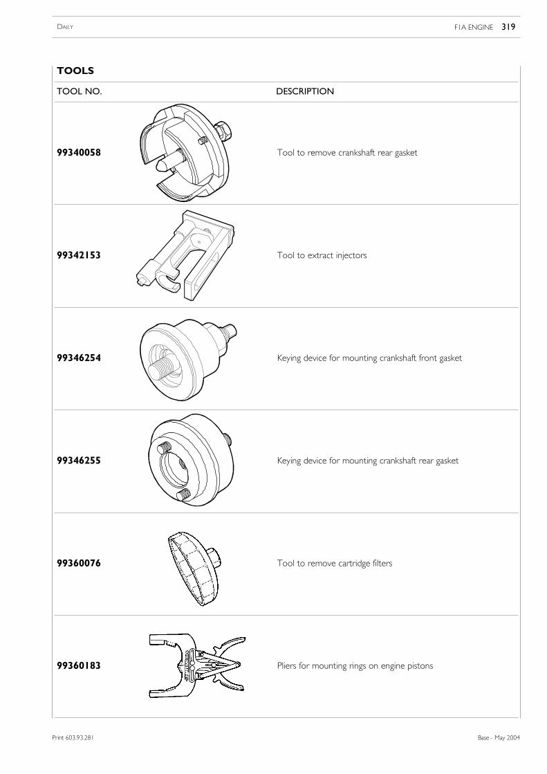
99346254 Keying device for mounting crankshaft front gasket
99346255 Keying device for mounting crankshaft rear gasket
99360076 Tool to remove cartridge filters
99360183 Pliers for mounting rings on engine pistons
320 F1A ENGINE DAILY
Base - May 2004 Print 603.93.281
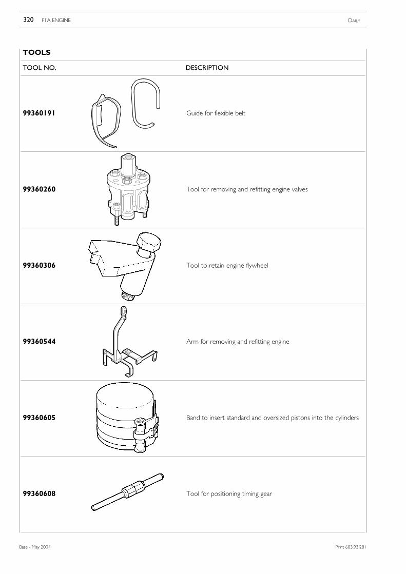
TOOLS
TOOL NO. DESCRIPTION
99360191 Guide for flexible belt
99360260 Tool for removing and refitting engine valves
99360306 Tool to retain engine flywheel
99360544 Arm for removing and refitting engine
99360605 Band to insert standard and oversized pistons into the cylinders
99360608 Tool for positioning timing gear
Revi - February 2005
F1A ENGINE 321DAILY
Print 603.93.281/A Base - May 2004
Print 603.93.281/A
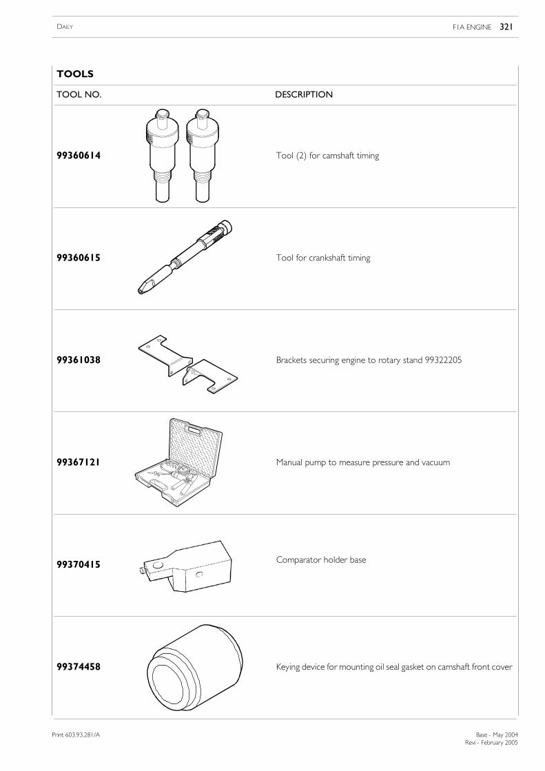
TOOLS
TOOL NO. DESCRIPTION
99360614 Tool (2) for camshaft timing
99360615 Tool for crankshaft timing
99361038 Brackets securing engine to rotary stand 99322205
99367121 Manual pump to measure pressure and vacuum
99370415 Comparator holder base
99374458 Keying device for mounting oil seal gasket on camshaft front cover
Revi - February 2005
322 F1A ENGINE DAILY
Base - May 2004 Print 603.93.281/A
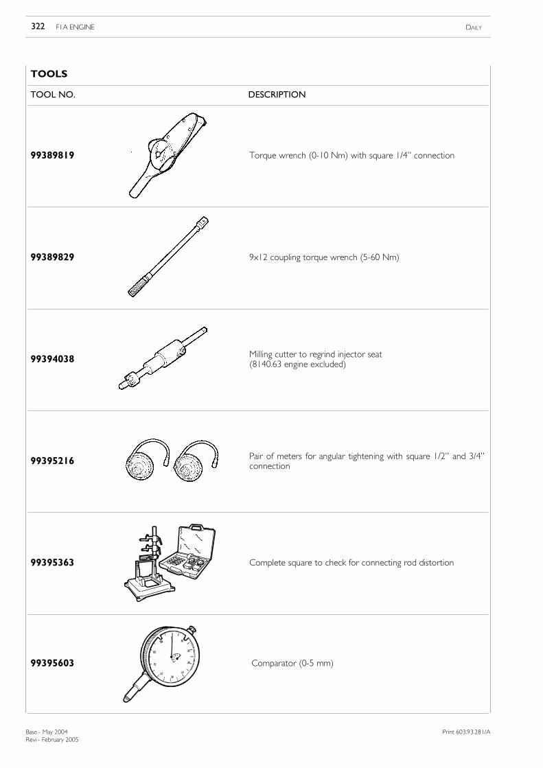
TOOLS
TOOL NO. DESCRIPTION
99389819 Torque wrench (0-10 Nm) with square 1/4” connection
99389829 9x12 coupling torque wrench (5-60 Nm)
99394038 Milling cutter to regrind injector seat(8140.63 engine excluded)
99395216 Pair of meters for angular tightening with square 1/2” and 3/4”connection
99395363 Complete square to check for connecting rod distortion
99395603 Comparator (0-5 mm)
Revi - February 2005
F1A ENGINE 323DAILY
Print 603.93.281/A Base - May 2004
Print 603.93.281/A
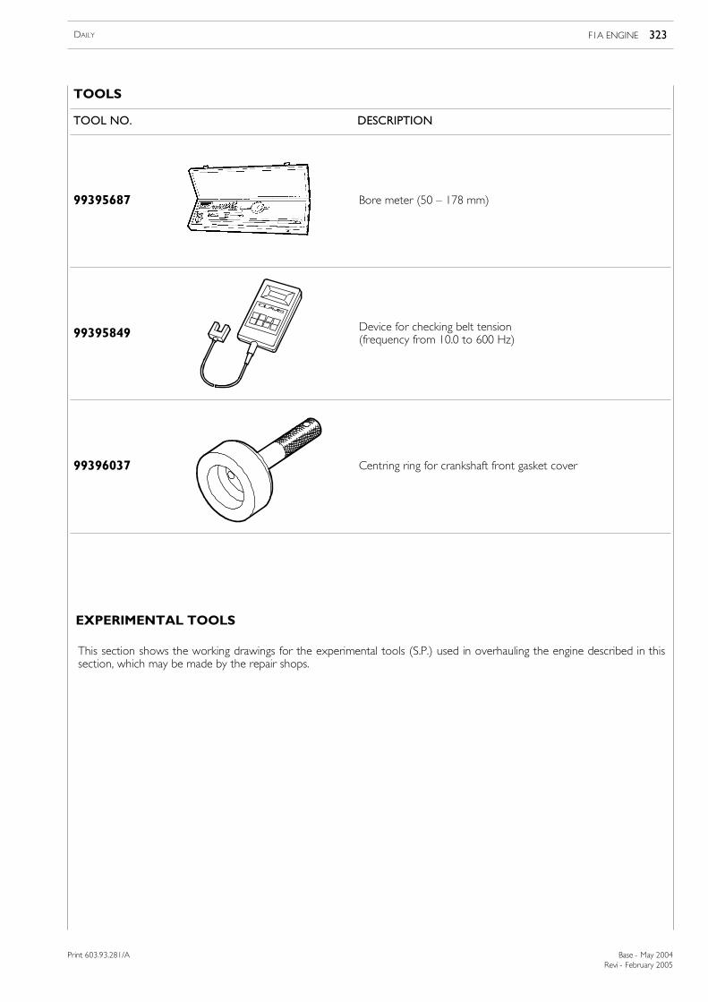
TOOLS
TOOL NO. DESCRIPTION
99395687 Bore meter (50 — 178 mm)
99395849 Device for checking belt tension(frequency from 10.0 to 600 Hz)
99396037 Centring ring for crankshaft front gasket cover
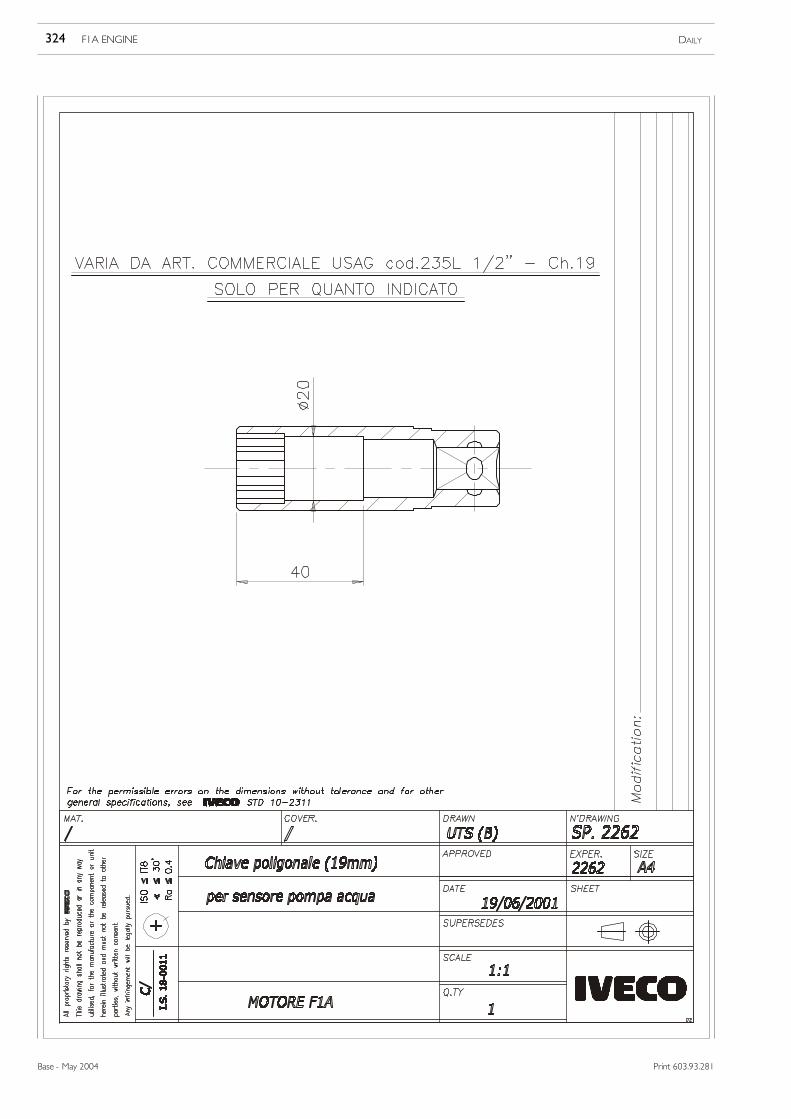
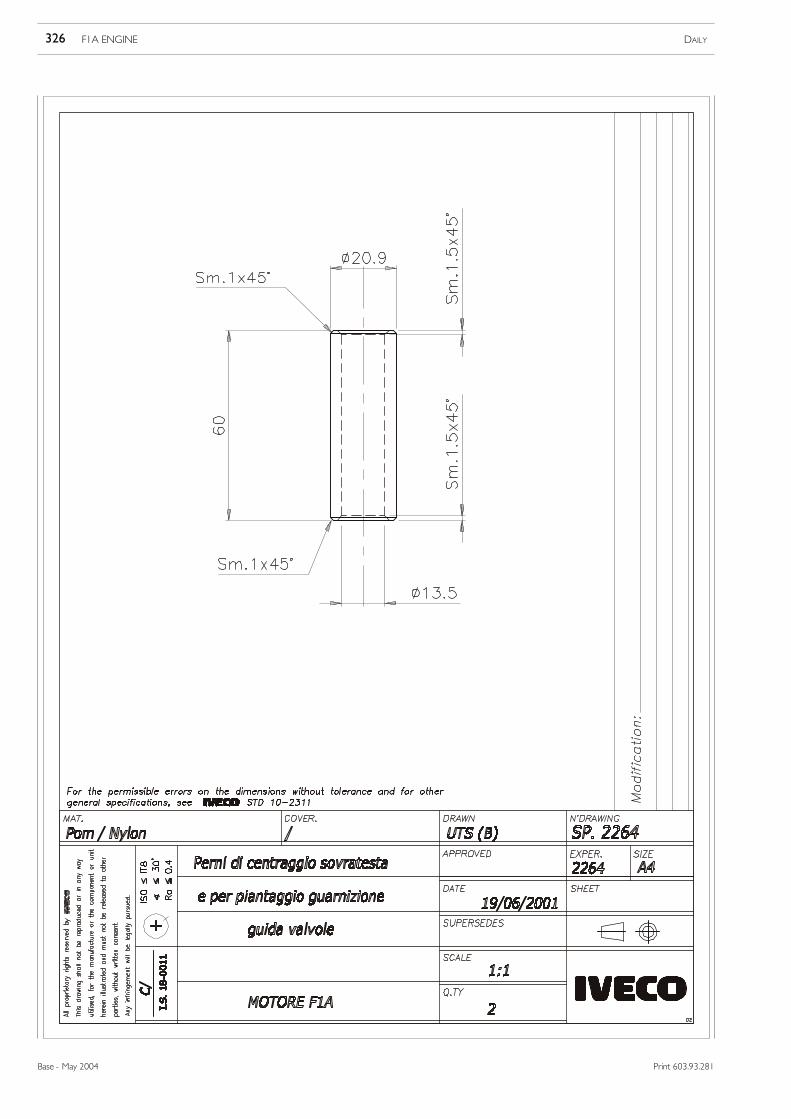
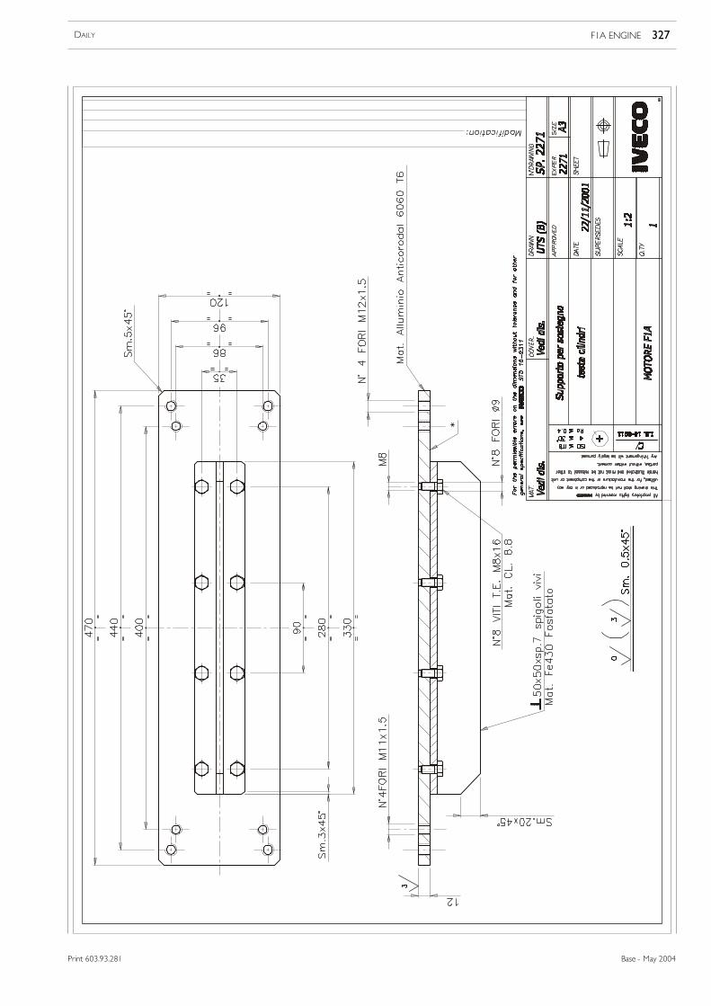
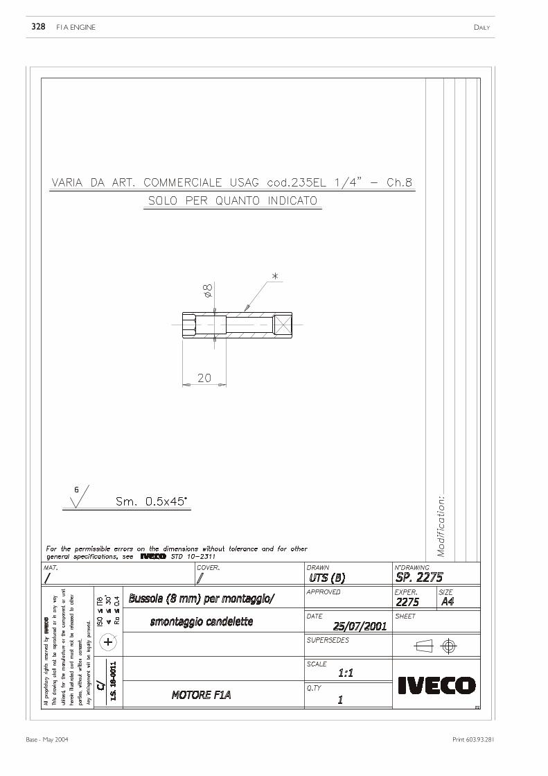
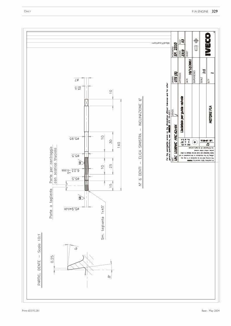
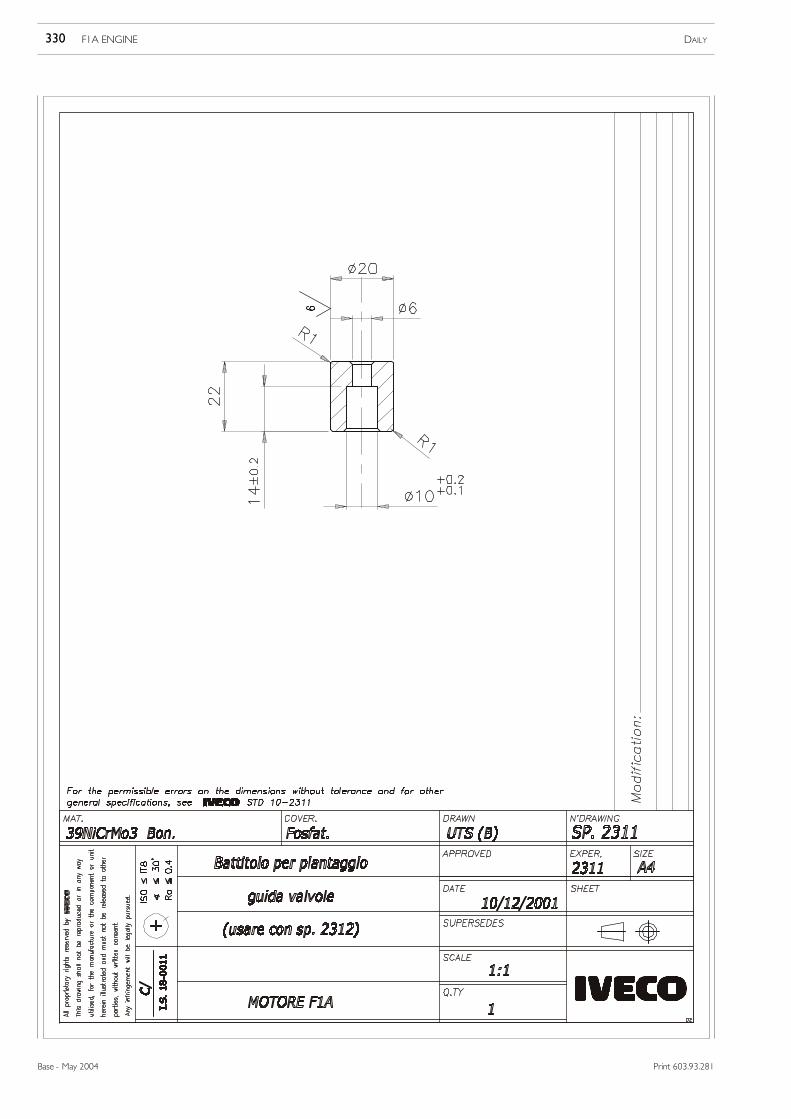
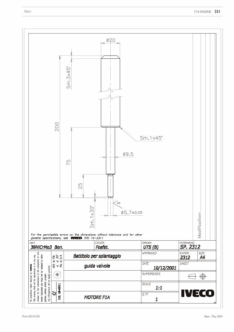
EXPERIMENTAL TOOLS
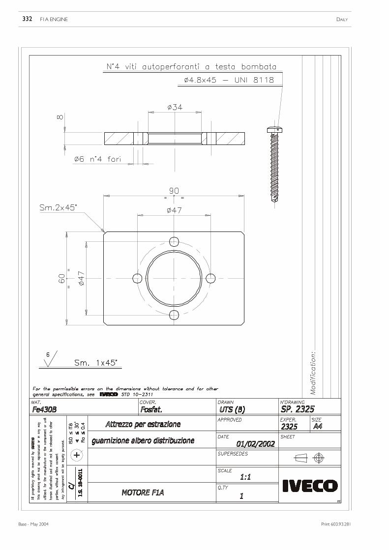
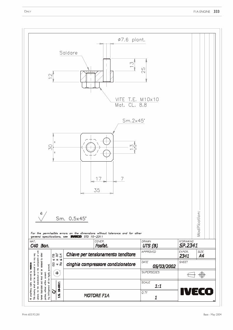
This section shows the working drawings for the experimental tools (S.P.) used in overhauling the engine described in thissection, which may be made by the repair shops.
324 F1A ENGINE DAILY
Base - May 2004 Print 603.93.281
Print 603.93.281
F1A ENGINE 325DAILY
Base - May 2004Print 603.93.281
F1A ENGINE DAILY326
Base - May 2004 Print 603.93.281
F1A ENGINE 327DAILY
Base - May 2004Print 603.93.281
F1A ENGINE DAILY328
Base - May 2004 Print 603.93.281
F1A ENGINE 329DAILY
Base - May 2004Print 603.93.281
F1A ENGINE DAILY330
Base - May 2004 Print 603.93.281
F1A ENGINE 331DAILY
Base - May 2004Print 603.93.281
F1A ENGINE DAILY332
Base - May 2004 Print 603.93.281
F1A ENGINE 333DAILY
Base - May 2004Print 603.93.281
F1A ENGINE DAILY334
Base - May 2004 Print 603.93.281
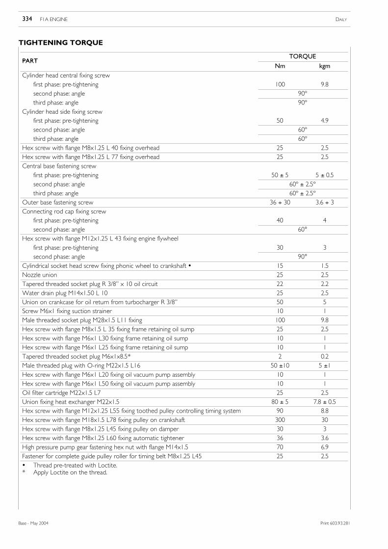
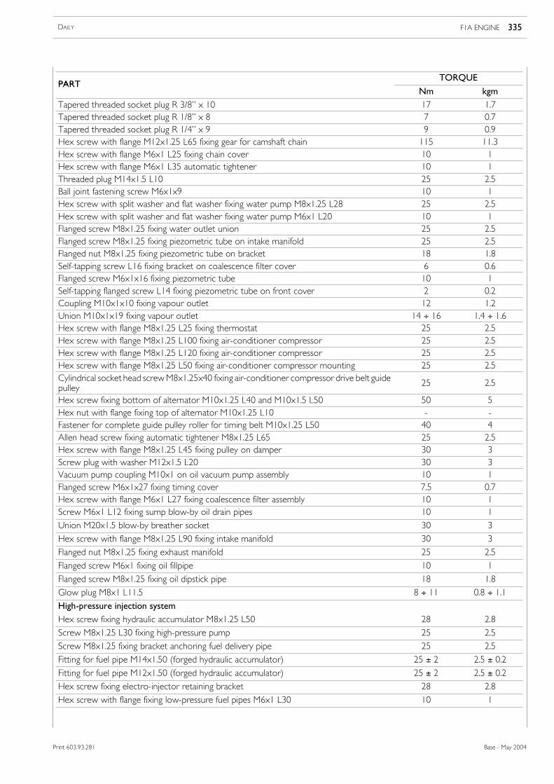
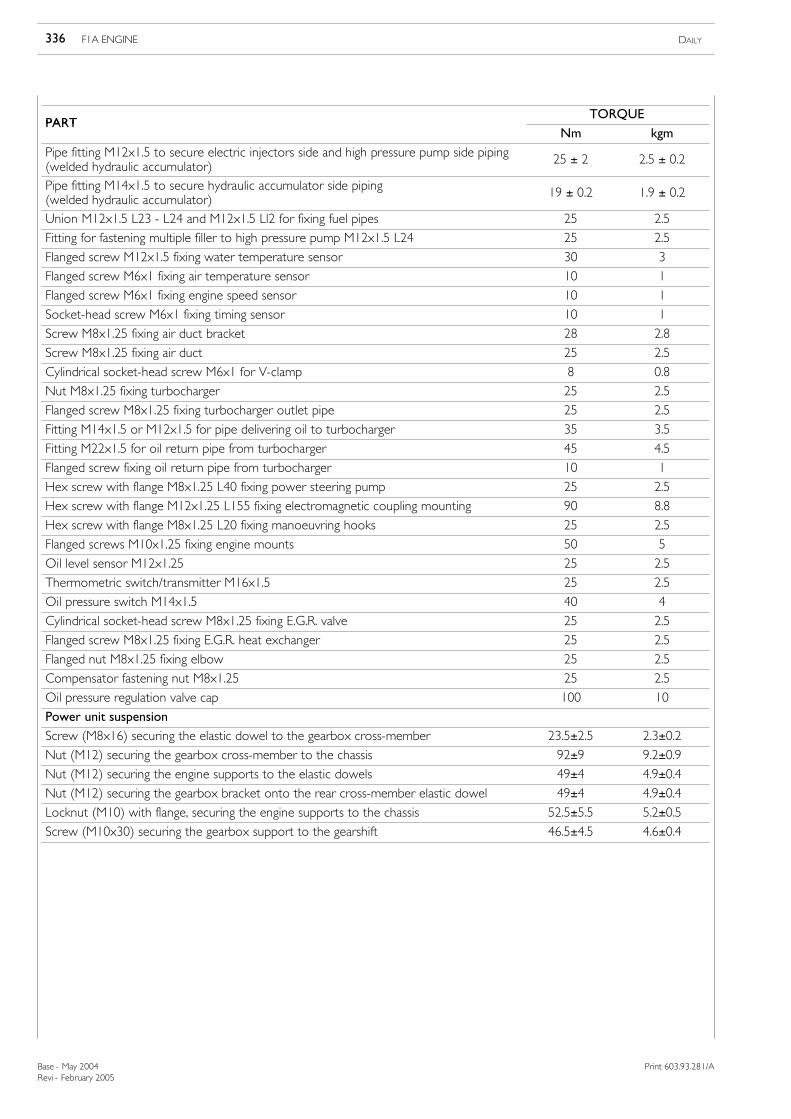
TIGHTENING TORQUE
PARTTORQUE
PARTNm kgm
Cylinder head central fixing screwfirst phase: pre-tightening 100 9.8second phase: angle 90ºthird phase: angle 90º
Cylinder head side fixing screwfirst phase: pre-tightening 50 4.9second phase: angle 60ºthird phase: angle 60º
Hex screw with flange M8x1.25 L 40 fixing overhead 25 2.5Hex screw with flange M8x1.25 L 77 fixing overhead 25 2.5Central base fastening screw
Screw (M8x16) securing the elastic dowel to the gearbox cross-member 23.5±2.5 2.3±0.2
Nut (M12) securing the gearbox cross-member to the chassis 92±9 9.2±0.9
Nut (M12) securing the engine supports to the elastic dowels 49±4 4.9±0.4
Nut (M12) securing the gearbox bracket onto the rear cross-member elastic dowel 49±4 4.9±0.4
Locknut (M10) with flange, securing the engine supports to the chassis 52.5±5.5 5.2±0.5
Screw (M10x30) securing the gearbox support to the gearshift 46.5±4.5 4.6±0.4
75815
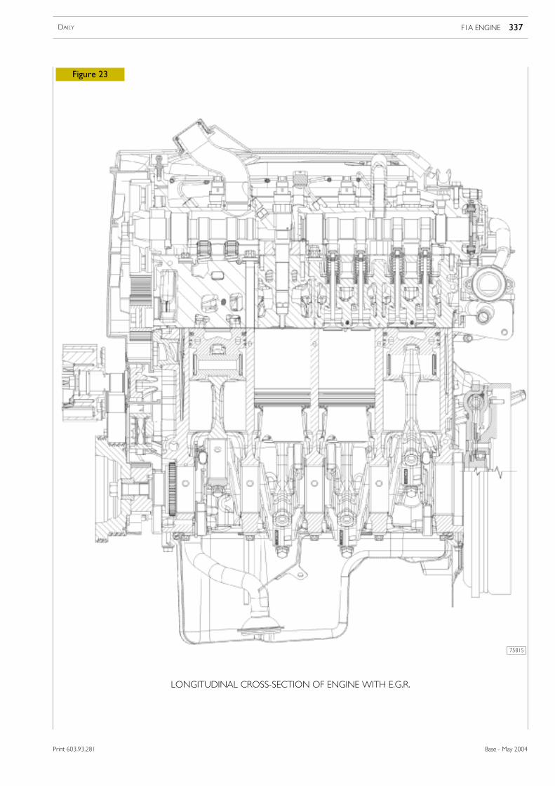
Figure 23
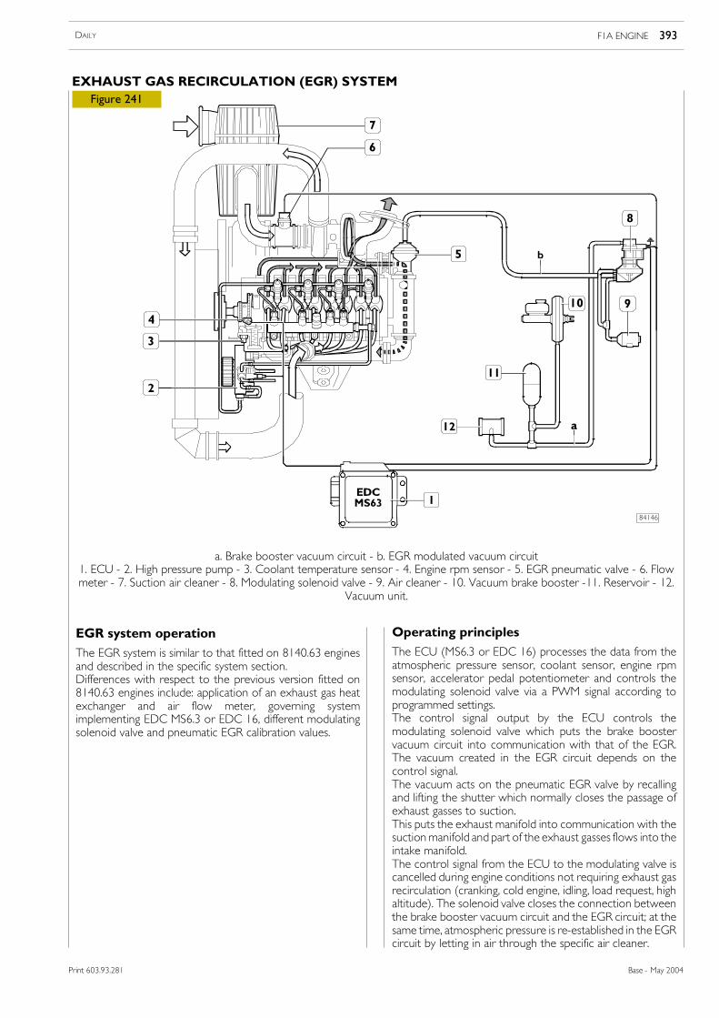
LONGITUDINAL CROSS-SECTION OF ENGINE WITH E.G.R.
F1A ENGINE 337DAILY
Base - May 2004Print 603.93.281
75816
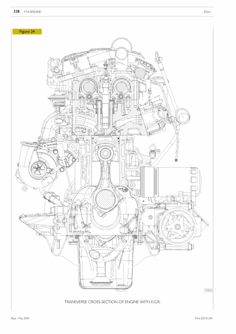
Figure 24
TRANSVERSE CROSS-SECTION OF ENGINE WITH E.G.R.
F1A ENGINE DAILY338
Base - May 2004 Print 603.93.281
75245
75246
75247
75248
Figure 25
Figure 26
Figure 27
Figure 28
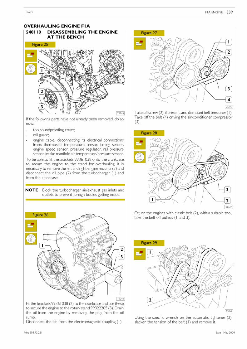
540110 DISASSEMBLING THE ENGINEAT THE BENCH
If the following parts have not already been removed, do sonow:
- top soundproofing cover;- rail guard;- engine cable, disconnecting its electrical connections
from: thermostat temperature sensor, timing sensor,engine speed sensor, pressure regulator, rail pressuresensor, intake manifold air temperature/pressure sensor.
To be able to fit the brackets 99361038 onto the crankcaseto secure the engine to the stand for overhauling, it isnecessary to remove the left and right enginemounts (3) anddisconnect the oil pipe (2) from the turbocharger (1) andfrom the crankcase.
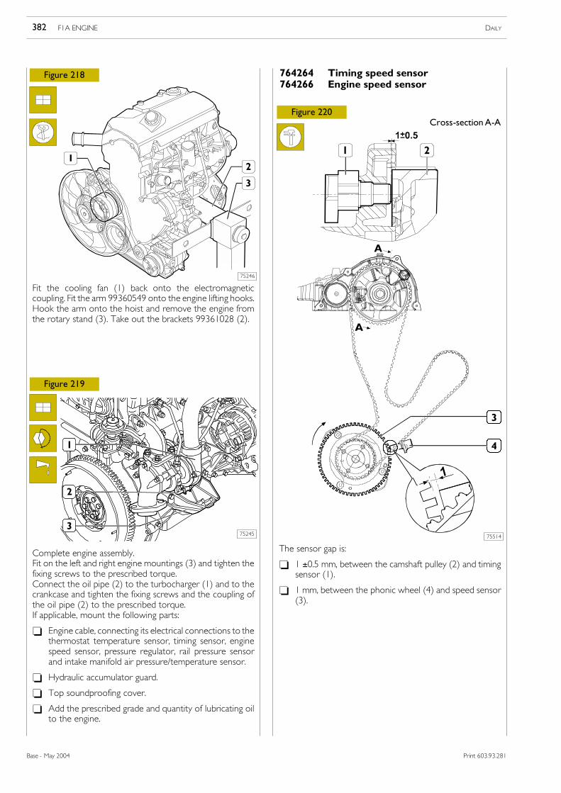
Fit the brackets 99361038 (2) to the crankcase and use theseto secure the engine to the rotary stand 99322205 (3). Drainthe oil from the engine by removing the plug from the oilsump.Disconnect the fan from the electromagnetic coupling (1).
Take off screw (2), if present, and dismount belt tensioner (1).Take off the belt (4) driving the air-conditioner compressor(3).
Using the specific wrench on the automatic tightener (2),slacken the tension of the belt (1) and remove it.
Block the turbocharger air/exhaust gas inlets andoutlets to prevent foreign bodies getting inside.
NOTE
Figure 29
88614
Or, on the engines with elastic belt (2), with a suitable tool,take the belt off pulleys (1 and 3).
F1A ENGINE 339DAILY
Base - May 2004Print 603.93.281
OVERHAULING ENGINE F1A
75249
75251
75250
75252
75253
75254
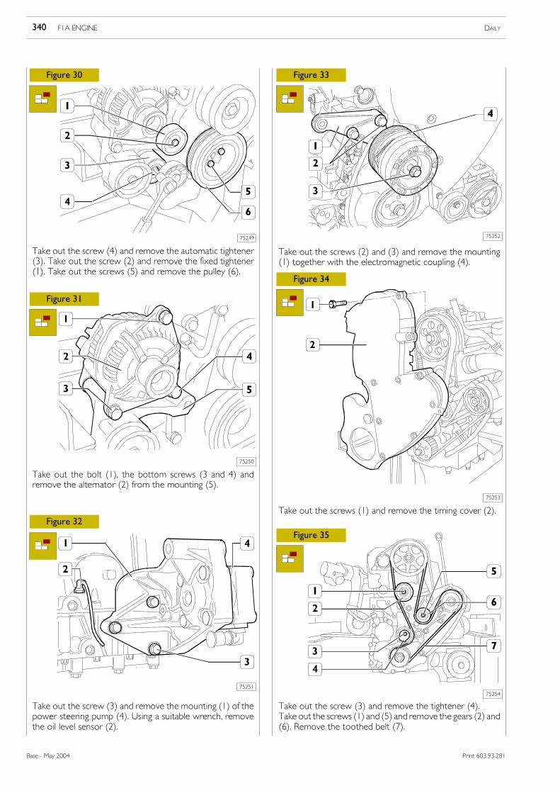
Figure 30
Figure 31
Figure 32
Figure 33
Figure 34
Figure 35
Take out the screw (4) and remove the automatic tightener(3). Take out the screw (2) and remove the fixed tightener(1). Take out the screws (5) and remove the pulley (6).
Take out the bolt (1), the bottom screws (3 and 4) andremove the alternator (2) from the mounting (5).
Take out the screw (3) and remove the mounting (1) of thepower steering pump (4). Using a suitable wrench, removethe oil level sensor (2).
Take out the screws (2) and (3) and remove the mounting(1) together with the electromagnetic coupling (4).
Take out the screws (1) and remove the timing cover (2).
Take out the screw (3) and remove the tightener (4).Take out the screws (1) and (5) and remove the gears (2) and(6). Remove the toothed belt (7).
F1A ENGINE DAILY340
Base - May 2004 Print 603.93.281
75255
75257
75256
75258
75259
75260
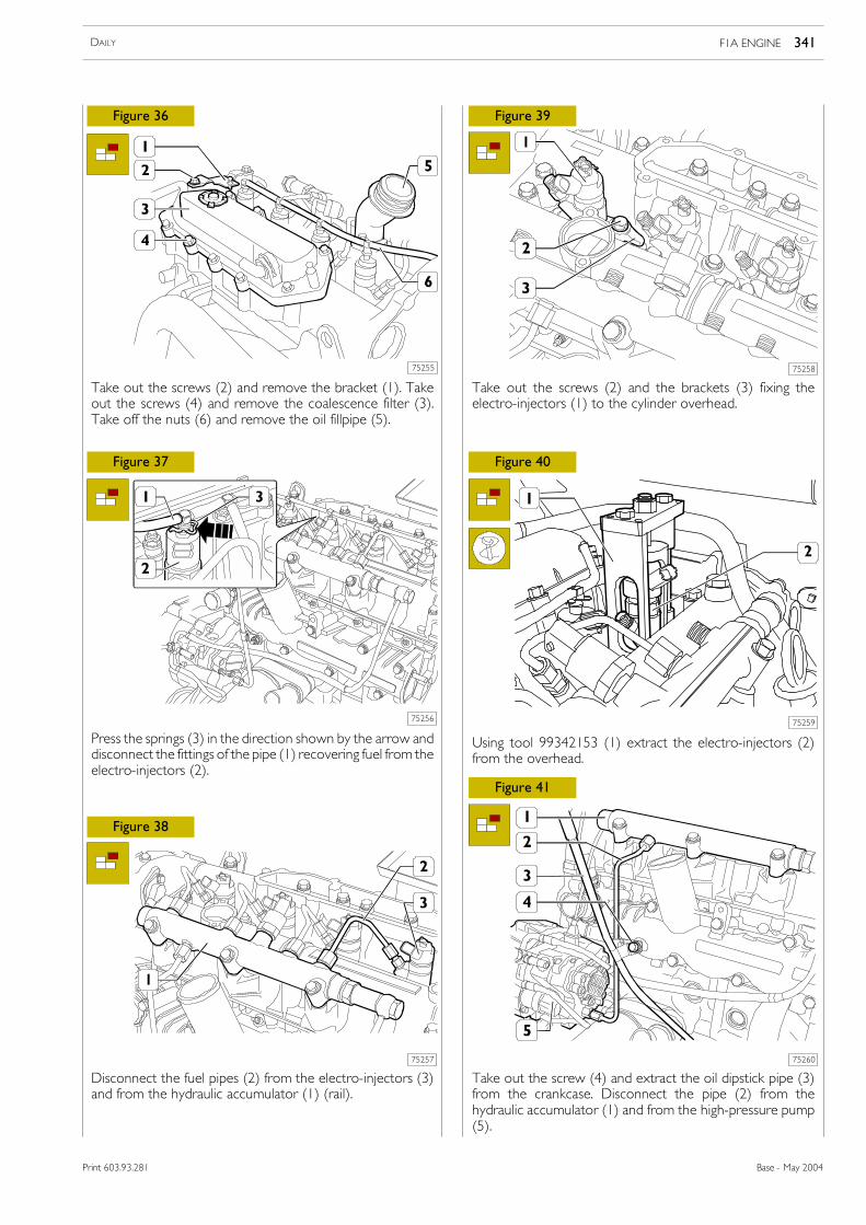
Figure 36
Figure 37
Figure 38
Figure 39
Figure 40
Figure 41
Take out the screws (2) and remove the bracket (1). Takeout the screws (4) and remove the coalescence filter (3).Take off the nuts (6) and remove the oil fillpipe (5).
Press the springs (3) in the direction shown by the arrow anddisconnect the fittings of the pipe (1) recovering fuel from theelectro-injectors (2).
Disconnect the fuel pipes (2) from the electro-injectors (3)and from the hydraulic accumulator (1) (rail).
Take out the screws (2) and the brackets (3) fixing theelectro-injectors (1) to the cylinder overhead.
Using tool 99342153 (1) extract the electro-injectors (2)from the overhead.
Take out the screw (4) and extract the oil dipstick pipe (3)from the crankcase. Disconnect the pipe (2) from thehydraulic accumulator (1) and from the high-pressure pump(5).
F1A ENGINE 341DAILY
Base - May 2004Print 603.93.281
75261
75263
75262
75264
75265
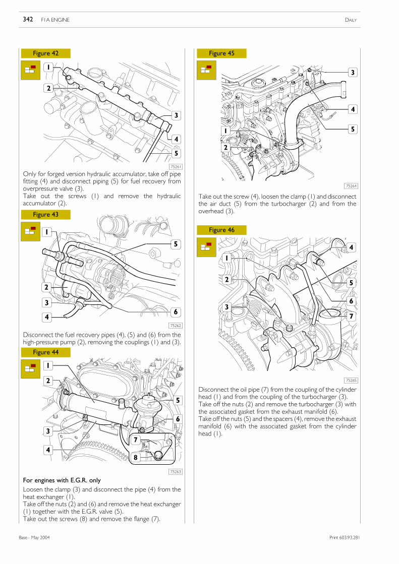
Figure 42
Figure 43
Figure 44
Figure 45
Figure 46
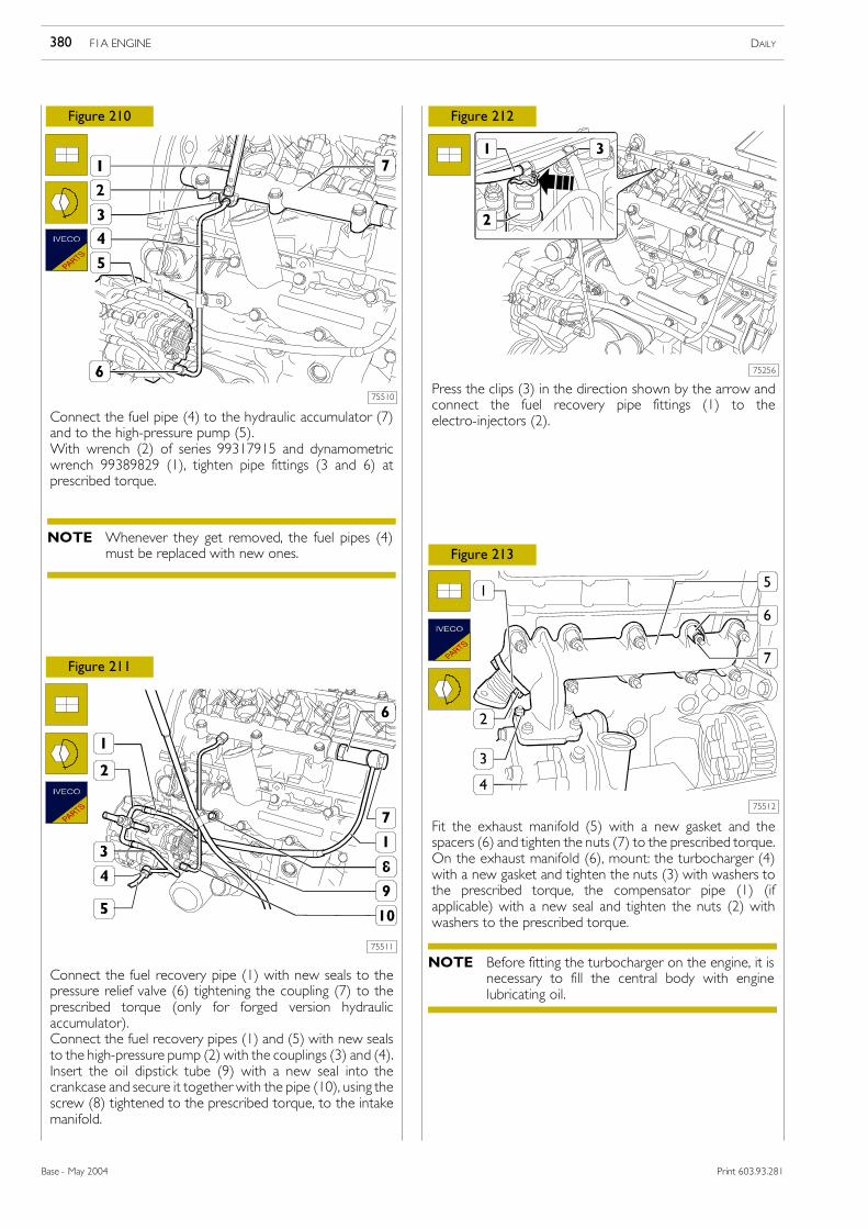
Only for forged version hydraulic accumulator, take off pipefitting (4) and disconnect piping (5) for fuel recovery fromoverpressure valve (3).Take out the screws (1) and remove the hydraulicaccumulator (2).
Disconnect the fuel recovery pipes (4), (5) and (6) from thehigh-pressure pump (2), removing the couplings (1) and (3).
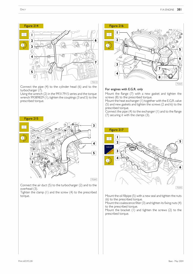
For engines with E.G.R. onlyLoosen the clamp (3) and disconnect the pipe (4) from theheat exchanger (1).Take off the nuts (2) and (6) and remove the heat exchanger(1) together with the E.G.R. valve (5).Take out the screws (8) and remove the flange (7).
Take out the screw (4), loosen the clamp (1) and disconnectthe air duct (5) from the turbocharger (2) and from theoverhead (3).
Disconnect the oil pipe (7) from the coupling of the cylinderhead (1) and from the coupling of the turbocharger (3).Take off the nuts (2) and remove the turbocharger (3) withthe associated gasket from the exhaust manifold (6).Take off the nuts (5) and the spacers (4), remove the exhaustmanifold (6) with the associated gasket from the cylinderhead (1).
F1A ENGINE DAILY342
Base - May 2004 Print 603.93.281
75266
75268
75267
75269
75270
75271
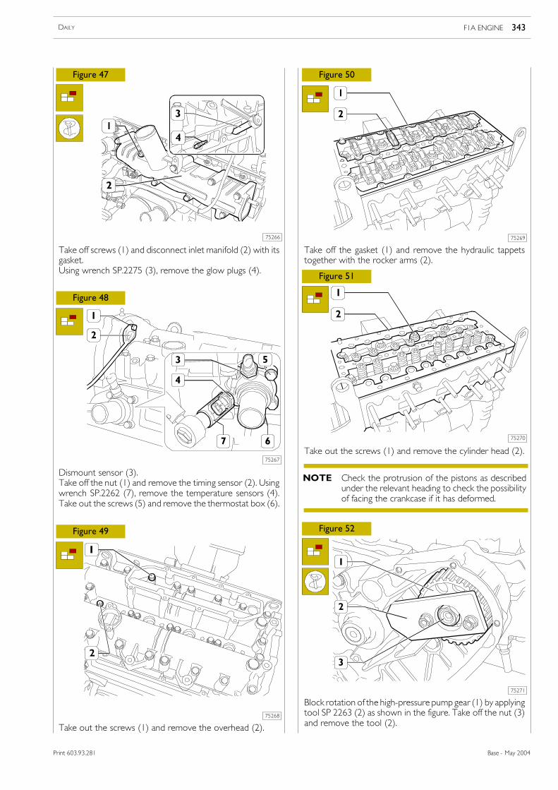
Figure 47
Figure 48
Figure 49
Figure 50
Figure 51
Figure 52
Take off screws (1) and disconnect inlet manifold (2) with itsgasket.Using wrench SP.2275 (3), remove the glow plugs (4).
Dismount sensor (3).Take off the nut (1) and remove the timing sensor (2). Usingwrench SP.2262 (7), remove the temperature sensors (4).Take out the screws (5) and remove the thermostat box (6).
Take out the screws (1) and remove the overhead (2).
Take off the gasket (1) and remove the hydraulic tappetstogether with the rocker arms (2).
Take out the screws (1) and remove the cylinder head (2).
Block rotation of the high-pressure pump gear (1) by applyingtool SP 2263 (2) as shown in the figure. Take off the nut (3)and remove the tool (2).
Check the protrusion of the pistons as describedunder the relevant heading to check the possibilityof facing the crankcase if it has deformed.
NOTE
F1A ENGINE 343DAILY
Base - May 2004Print 603.93.281
75272
75274
75273
75275
75276
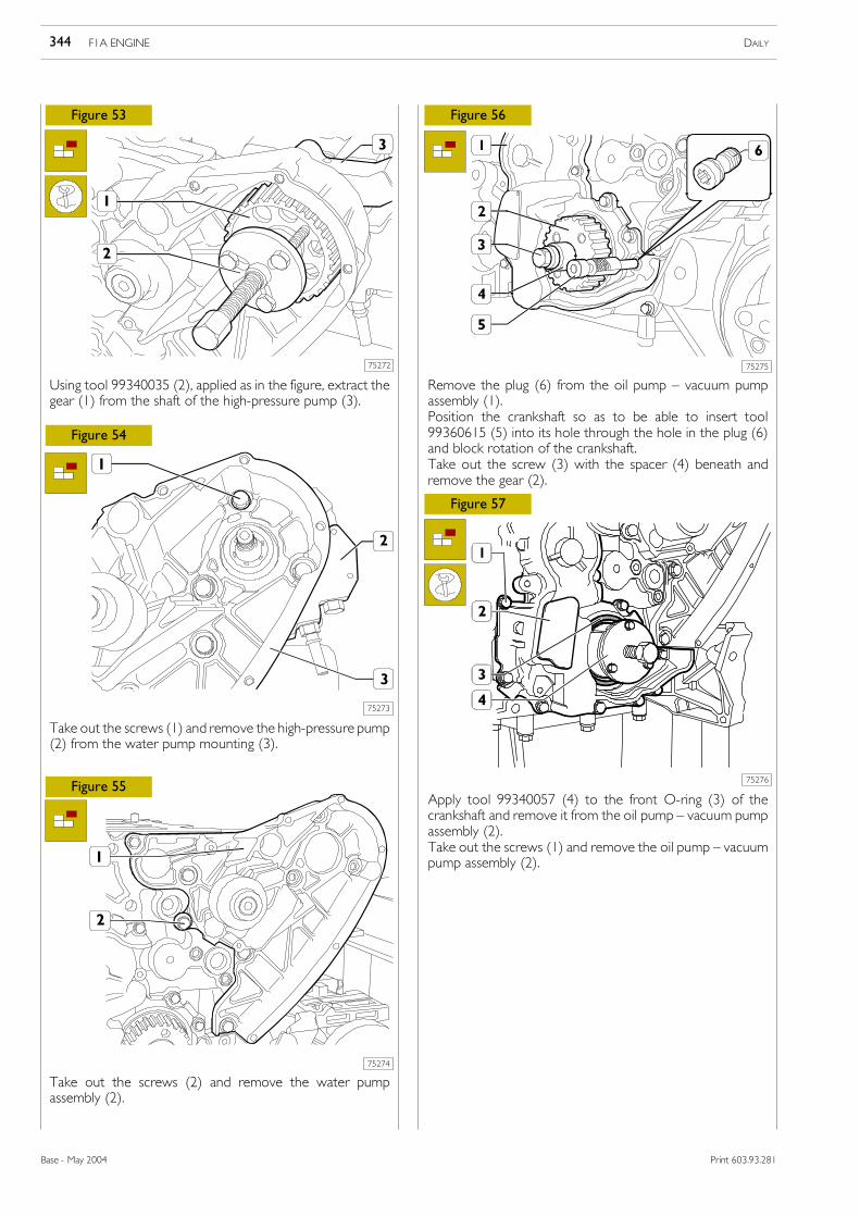
Figure 53
Figure 54
Figure 55
Figure 56
Figure 57
Using tool 99340035 (2), applied as in the figure, extract thegear (1) from the shaft of the high-pressure pump (3).
Take out the screws (1) and remove the high-pressure pump(2) from the water pump mounting (3).
Take out the screws (2) and remove the water pumpassembly (2).
Remove the plug (6) from the oil pump � vacuum pumpassembly (1).Position the crankshaft so as to be able to insert tool99360615 (5) into its hole through the hole in the plug (6)and block rotation of the crankshaft.Take out the screw (3) with the spacer (4) beneath andremove the gear (2).
Apply tool 99340057 (4) to the front O-ring (3) of thecrankshaft and remove it from the oil pump � vacuum pumpassembly (2).Take out the screws (1) and remove the oil pump � vacuumpump assembly (2).
F1A ENGINE DAILY344
Base - May 2004 Print 603.93.281
75277
75279
75278
75280
75281
75282
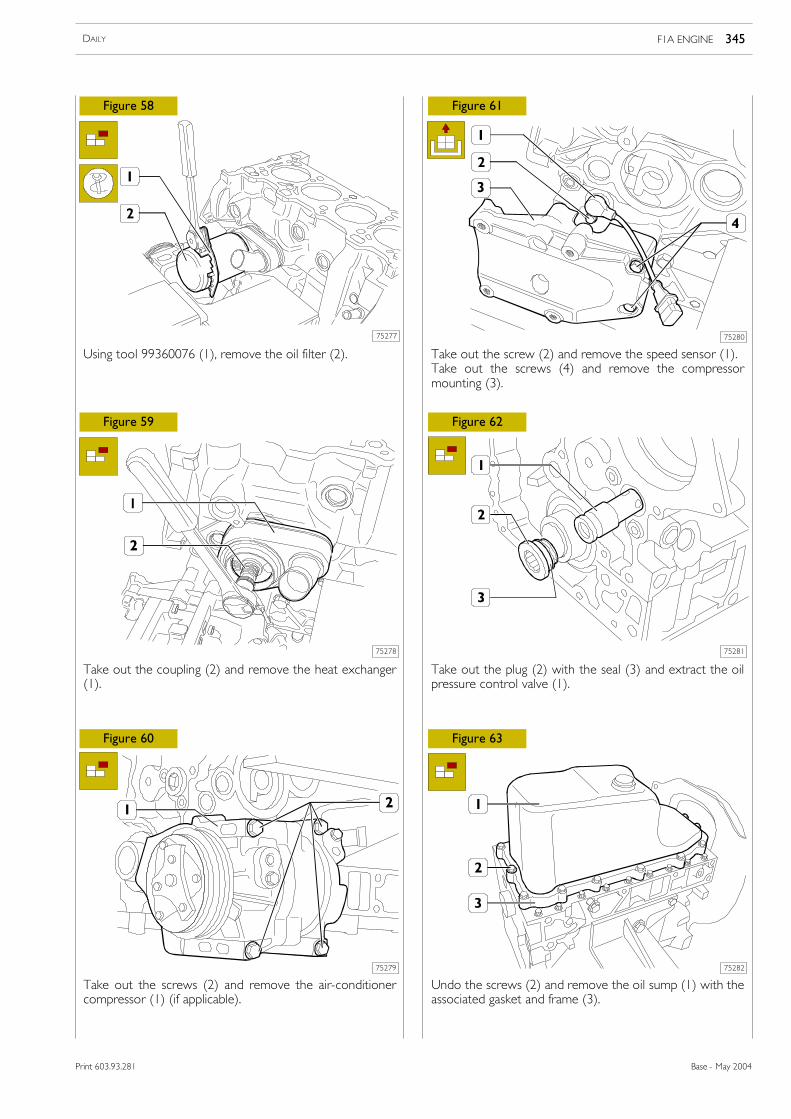
Figure 58
Figure 59
Figure 60
Figure 61
Figure 62
Figure 63
Using tool 99360076 (1), remove the oil filter (2).
Take out the coupling (2) and remove the heat exchanger(1).
Take out the screws (2) and remove the air-conditionercompressor (1) (if applicable).
Take out the screw (2) and remove the speed sensor (1).Take out the screws (4) and remove the compressormounting (3).
Take out the plug (2) with the seal (3) and extract the oilpressure control valve (1).
Undo the screws (2) and remove the oil sump (1) with theassociated gasket and frame (3).
F1A ENGINE 345DAILY
Base - May 2004Print 603.93.281
75283
75284
75285
75286
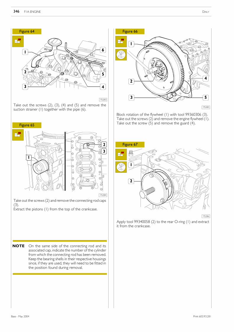
Figure 64
Figure 65
Figure 66
Figure 67
Take out the screws (2), (3), (4) and (5) and remove thesuction strainer (1) together with the pipe (6).
Take out the screws (2) and remove the connecting rod caps(3).Extract the pistons (1) from the top of the crankcase.
Block rotation of the flywheel (1) with tool 99360306 (3).Take out the screws (2) and remove the engine flywheel (1).Take out the screw (5) and remove the guard (4).
Apply tool 99340058 (2) to the rear O-ring (1) and extractit from the crankcase.
On the same side of the connecting rod and itsassociated cap, indicate the number of the cylinderfrom which the connecting rod has been removed.Keep the bearing shells in their respective housingssince, if they are used, they will need to be fitted inthe position found during removal.
NOTE
F1A ENGINE DAILY346
Base - May 2004 Print 603.93.281
75287
75289
75288
75290
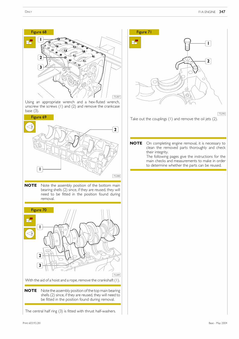
Figure 68
Figure 69
Figure 70
Figure 71
Using an appropriate wrench and a hex-fluted wrench,unscrew the screws (1) and (2) and remove the crankcasebase (3).
With the aid of a hoist and a rope, remove the crankshaft (1).
Take out the couplings (1) and remove the oil jets (2).
The central half ring (3) is fitted with thrust half-washers.
Note the assembly position of the bottom mainbearing shells (2) since, if they are reused, they willneed to be fitted in the position found duringremoval.
NOTE
Note the assembly position of the topmain bearingshells (2) since, if they are reused, they will need tobe fitted in the position found during removal.
NOTE
On completing engine removal, it is necessary toclean the removed parts thoroughly and checktheir integrity.The following pages give the instructions for themain checks and measurements to make in orderto determine whether the parts can be reused.
NOTE
F1A ENGINE 347DAILY
Base - May 2004Print 603.93.281
The measurements must be made for each single cylinder atthree different heights up the liner and on two planes at rightangles to each other: one parallel to the longitudinal axis ofthe engine (B) and the perpendicular (A); the greatest wearis generally found on this last plane with the firstmeasurement.On finding ovalization, taper or wear, go ahead andbore/grind and finish the face of the cylinder liners. Therefacing of the cylinder liners should be done in relation tothe diameter of the pistons supplied as spare parts oversizedby 0.4 mm of the nominal value and to the prescribedassembly clearance.
18837
75292
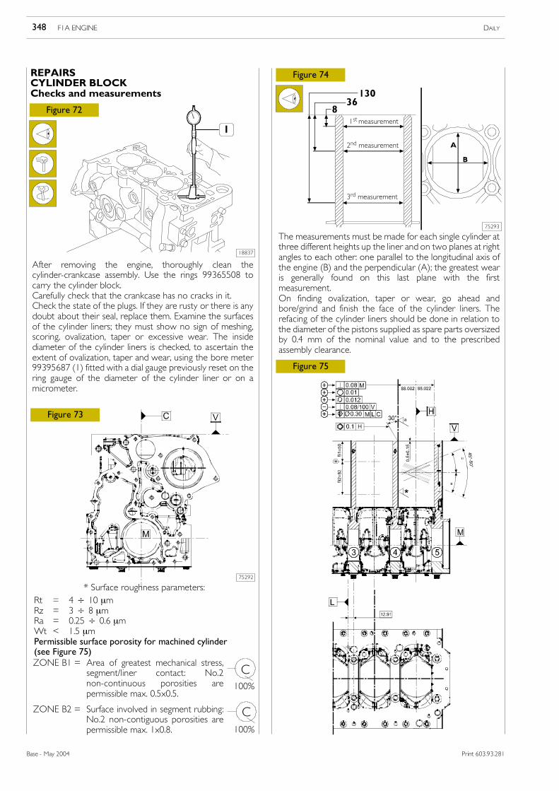
Figure 72
Figure 73
After removing the engine, thoroughly clean thecylinder-crankcase assembly. Use the rings 99365508 tocarry the cylinder block.Carefully check that the crankcase has no cracks in it.Check the state of the plugs. If they are rusty or there is anydoubt about their seal, replace them. Examine the surfacesof the cylinder liners; they must show no sign of meshing,scoring, ovalization, taper or excessive wear. The insidediameter of the cylinder liners is checked, to ascertain theextent of ovalization, taper and wear, using the bore meter99395687 (1) fitted with a dial gauge previously reset on thering gauge of the diameter of the cylinder liner or on amicrometer.
ZONE B2 = Surface involved in segment rubbing:No.2 non-contiguous porosities arepermissible max. 1x0.8.
C
C
100%
100%
75293
Figure 75
1st measurement
2nd measurement
3rd measurement
F1A ENGINE DAILY348
Base - May 2004 Print 603.93.281
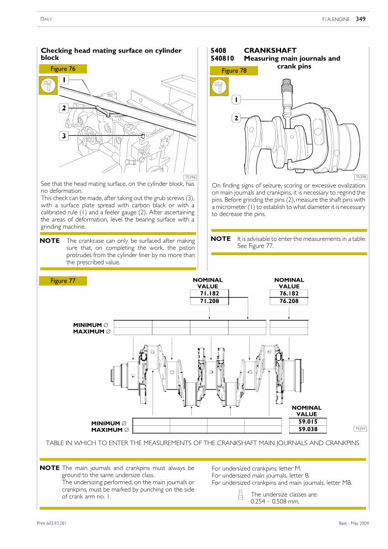
For undersized crankpins, letter M.For undersized main journals, letter B.For undersized crankpins and main journals, letter MB.
See that the head mating surface, on the cylinder block, hasno deformation.This check can be made, after taking out the grub screws (3),with a surface plate spread with carbon black or with acalibrated rule (1) and a feeler gauge (2). After ascertainingthe areas of deformation, level the bearing surface with agrinding machine.
75296
Figure 76
Figure 77
75297
Figure 78
The main journals and crankpins must always beground to the same undersize class.The undersizing performed, on the main journals orcrankpins, must be marked by punching on the sideof crank arm no. 1. The undersize classes are:
0.254 � 0.508 mm.
TABLE IN WHICH TO ENTER THE MEASUREMENTS OF THE CRANKSHAFT MAIN JOURNALS AND CRANKPINS
5408 CRANKSHAFT540810 Measuring main journals and
crank pins
Checking head mating surface on cylinderblock
On finding signs of seizure, scoring or excessive ovalizationon main journals and crankpins, it is necessary to regrind thepins. Before grinding the pins (2), measure the shaft pins witha micrometer (1) to establish towhat diameter it is necessaryto decrease the pins.
75298
NOMINALVALUE
NOMINALVALUE
NOMINALVALUE
MINIMUM ∅MAXIMUM ∅
MINIMUM ∅MAXIMUM ∅
The crankcase can only be surfaced after makingsure that, on completing the work, the pistonprotrudes from the cylinder liner by no more thanthe prescribed value.
NOTE It is advisable to enter the measurements in a table.See Figure 77.
NOTE
NOTE
F1A ENGINE 349DAILY
Base - May 2004Print 603.93.281
75299
45066
Figure 79
Figure 80
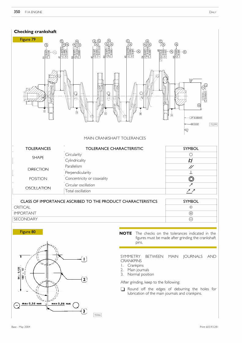
MAIN CRANKSHAFT TOLERANCES
SYMMETRY BETWEEN MAIN JOURNALS ANDCRANKPINS1. Crankpins2. Main journals3. Normal position
Checking crankshaft
After grinding, keep to the following:
- Round off the edges of deburring the holes forlubrication of the main journals and crankpins.
94±0,125
180°
±15�
The checks on the tolerances indicated in thefigures must be made after grinding the crankshaftpins.
NOTE
F1A ENGINE DAILY350
Base - May 2004 Print 603.93.281
TOLERANCES TOLERANCE CHARACTERISTIC SYMBOL
SHAPECircularity ○
SHAPECylindricality
DIRECTIONParallelism
DIRECTIONPerpendicularity ⊥
POSITION Concentricity or coaxiality
OSCILLATIONCircular oscillation ↗
OSCILLATIONTotal oscillation ↗↗
CLASS OF IMPORTANCE ASCRIBED TO THE PRODUCT CHARACTERISTICS SYMBOL
CRITICAL E
IMPORTANT ⊕SECONDARY ⊝
75300
75302
75301
75303
75304
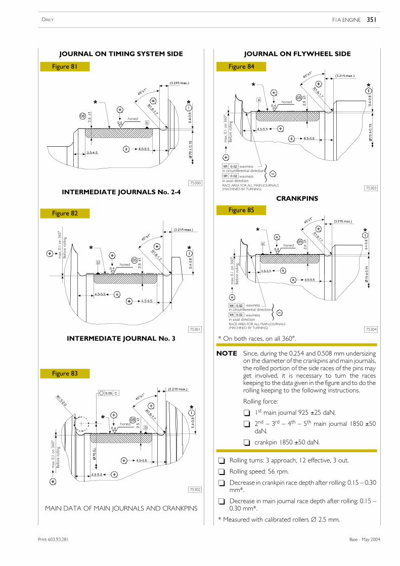
Figure 81
Figure 82
Figure 83
Figure 84
Figure 85
INTERMEDIATE JOURNALS No. 2-4
INTERMEDIATE JOURNAL No. 3
CRANKPINS
* On both races, on all 360°.
- Rolling turns: 3 approach, 12 effective, 3 out.
- Rolling speed: 56 rpm.
- Decrease in crankpin race depth after rolling: 0.15 � 0.30mm*.
- Decrease in main journal race depth after rolling: 0.15 �0.30 mm*.
* Measured with calibrated rollers ∅ 2.5 mm.
JOURNAL ON TIMING SYSTEM SIDE JOURNAL ON FLYWHEEL SIDE
MAIN DATA OF MAIN JOURNALS AND CRANKPINS
max.0.1on360°
Beforerolling
honed
honed
max.0.1on360°
Beforerolling
honed
max.0.1on360°
Beforerolling
honed
wavinessin circumferential direction
wavinessin axial directionRACE AREA FOR ALL MAIN JOURNALS(MACHINED BY TURNING)
max.0.1on360°
Beforerolling
honed
wavinessin circumferential direction
wavinessin axial directionRACE AREA FOR ALL MAIN JOURNALS(MACHINED BY TURNING)
Since, during the 0.254 and 0.508 mm undersizingon the diameter of the crankpins andmain journals,the rolled portion of the side races of the pins mayget involved, it is necessary to turn the raceskeeping to the data given in the figure and to do therolling keeping to the following instructions.
Rolling force:
- 1st main journal 925 ±25 daN.
- 2nd � 3rd � 4th � 5th main journal 1850 ±50daN.
- crankpin 1850 ±50 daN.
NOTE
F1A ENGINE 351DAILY
Base - May 2004Print 603.93.281
75305
75306
75307
75289
Figure 86
Figure 87
Figure 88
Figure 89
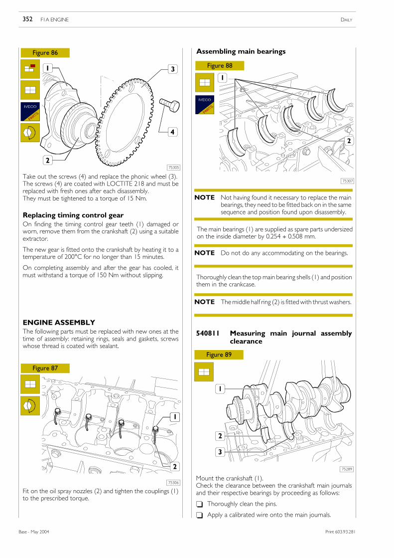
Take out the screws (4) and replace the phonic wheel (3).The screws (4) are coated with LOCTITE 218 and must bereplaced with fresh ones after each disassembly.They must be tightened to a torque of 15 Nm.
Replacing timing control gearOn finding the timing control gear teeth (1) damaged orworn, remove them from the crankshaft (2) using a suitableextractor.
The new gear is fitted onto the crankshaft by heating it to atemperature of 200°C for no longer than 15 minutes.
On completing assembly and after the gear has cooled, itmust withstand a torque of 150 Nm without slipping.
ENGINE ASSEMBLYThe following parts must be replaced with new ones at thetime of assembly: retaining rings, seals and gaskets, screwswhose thread is coated with sealant.
Fit on the oil spray nozzles (2) and tighten the couplings (1)to the prescribed torque.
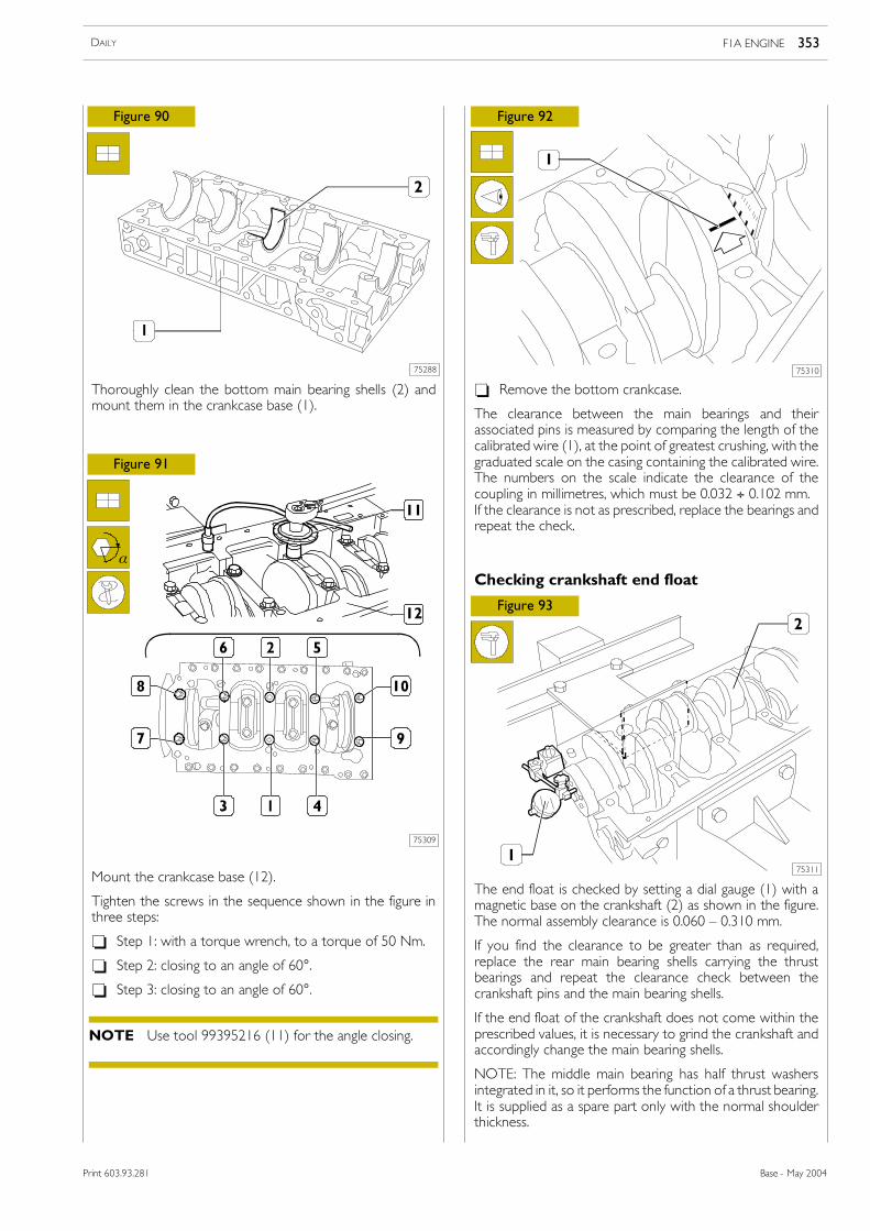
The main bearings (1) are supplied as spare parts undersizedon the inside diameter by 0.254 ÷ 0.508 mm.
540811 Measuring main journal assemblyclearance
Mount the crankshaft (1).Check the clearance between the crankshaft main journalsand their respective bearings by proceeding as follows:
- Thoroughly clean the pins.
- Apply a calibrated wire onto the main journals.
Assembling main bearings
Thoroughly clean the topmain bearing shells (1) and positionthem in the crankcase.
Not having found it necessary to replace the mainbearings, they need to be fitted back on in the samesequence and position found upon disassembly.
NOTE
Do not do any accommodating on the bearings.NOTE
Themiddle half ring (2) is fittedwith thrustwashers.NOTE
F1A ENGINE DAILY352
Base - May 2004 Print 603.93.281
75288
75309
75310
75311
Figure 90
Figure 91
Figure 92
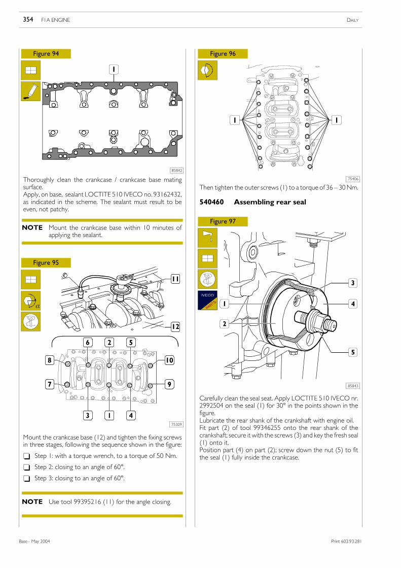
Thoroughly clean the bottom main bearing shells (2) andmount them in the crankcase base (1).
Mount the crankcase base (12).
Tighten the screws in the sequence shown in the figure inthree steps:
- Step 1: with a torque wrench, to a torque of 50 Nm.
- Step 2: closing to an angle of 60°.
- Step 3: closing to an angle of 60°.
The end float is checked by setting a dial gauge (1) with amagnetic base on the crankshaft (2) as shown in the figure.The normal assembly clearance is 0.060 � 0.310 mm.
If you find the clearance to be greater than as required,replace the rear main bearing shells carrying the thrustbearings and repeat the clearance check between thecrankshaft pins and the main bearing shells.
If the end float of the crankshaft does not come within theprescribed values, it is necessary to grind the crankshaft andaccordingly change the main bearing shells.
NOTE: The middle main bearing has half thrust washersintegrated in it, so it performs the function of a thrust bearing.It is supplied as a spare part only with the normal shoulderthickness.
α
Figure 93
- Remove the bottom crankcase.
The clearance between the main bearings and theirassociated pins is measured by comparing the length of thecalibrated wire (1), at the point of greatest crushing, with thegraduated scale on the casing containing the calibrated wire.The numbers on the scale indicate the clearance of thecoupling in millimetres, which must be 0.032 ÷ 0.102 mm.If the clearance is not as prescribed, replace the bearings andrepeat the check.
Checking crankshaft end float
Use tool 99395216 (11) for the angle closing.NOTE
F1A ENGINE 353DAILY
Base - May 2004Print 603.93.281
Print 603.43.351/D
85842
75309
75406
85843
Figure 94
Figure 95
Figure 96
Figure 97
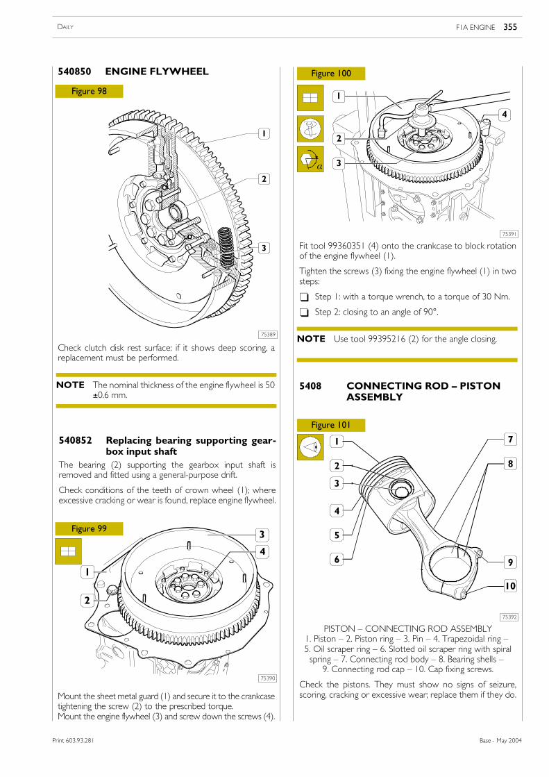
Thoroughly clean the crankcase / crankcase base matingsurface.Apply, on base, sealant LOCTITE 510 IVECO no. 93162432,as indicated in the scheme. The sealant must result to beeven, not patchy.
Mount the crankcase base (12) and tighten the fixing screwsin three stages, following the sequence shown in the figure:
- Step 1: with a torque wrench, to a torque of 50 Nm.
- Step 2: closing to an angle of 60°.
- Step 3: closing to an angle of 60°.
Then tighten the outer screws (1) to a torque of 36 � 30Nm.
Carefully clean the seal seat. Apply LOCTITE 510 IVECO nr.2992504 on the seal (1) for 30° in the points shown in thefigure.Lubricate the rear shank of the crankshaft with engine oil.Fit part (2) of tool 99346255 onto the rear shank of thecrankshaft; secure it with the screws (3) and key the fresh seal(1) onto it.Position part (4) on part (2); screw down the nut (5) to fitthe seal (1) fully inside the crankcase.
α
540460 Assembling rear seal
Mount the crankcase base within 10 minutes ofapplying the sealant.
NOTE
Use tool 99395216 (11) for the angle closing.NOTE
F1A ENGINE DAILY354
Base - May 2004 Print 603.93.281
Print 603.43.351/D
75389
75390
75391
75392
Figure 98
Figure 99
Figure 100
Figure 101
Check clutch disk rest surface: if it shows deep scoring, areplacement must be performed.
Mount the sheet metal guard (1) and secure it to the crankcasetightening the screw (2) to the prescribed torque.Mount the engine flywheel (3) and screw down the screws (4).
Fit tool 99360351 (4) onto the crankcase to block rotationof the engine flywheel (1).
Tighten the screws (3) fixing the engine flywheel (1) in twosteps:
- Step 1: with a torque wrench, to a torque of 30 Nm.
- Step 2: closing to an angle of 90°.
5408 CONNECTING ROD � PISTONASSEMBLY
PISTON � CONNECTING ROD ASSEMBLY1. Piston � 2. Piston ring � 3. Pin � 4. Trapezoidal ring �5. Oil scraper ring � 6. Slotted oil scraper ring with spiralspring � 7. Connecting rod body � 8. Bearing shells �9. Connecting rod cap � 10. Cap fixing screws.
Check the pistons. They must show no signs of seizure,scoring, cracking or excessive wear; replace them if they do.
The bearing (2) supporting the gearbox input shaft isremoved and fitted using a general-purpose drift.
Check conditions of the teeth of crown wheel (1); whereexcessive cracking or wear is found, replace engine flywheel.
The nominal thickness of the engine flywheel is 50±0.6 mm.
NOTE
Use tool 99395216 (2) for the angle closing.NOTE
F1A ENGINE 355DAILY
Base - May 2004Print 603.93.281
Print 603.43.351
75393
75394
Figure 102 Figure 103
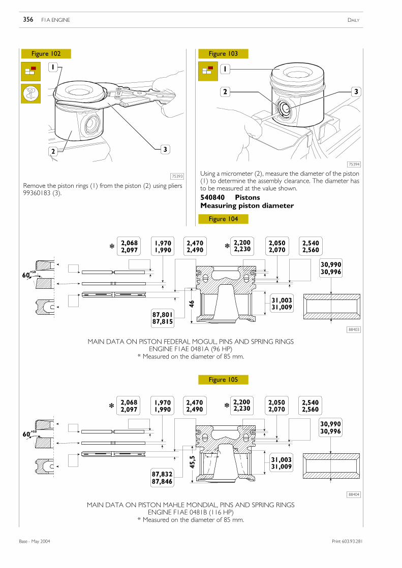
Remove the piston rings (1) from the piston (2) using pliers99360183 (3).
Using a micrometer (2), measure the diameter of the piston(1) to determine the assembly clearance. The diameter hasto be measured at the value shown.
MAIN DATA ON PISTON FEDERAL MOGUL, PINS AND SPRING RINGSENGINE F1AE 0481A (96 HP)
* Measured on the diameter of 85 mm.
88403
Figure 104
540840 PistonsMeasuring piston diameter
Figure 105
MAIN DATA ON PISTON MAHLE MONDIAL, PINS AND SPRING RINGSENGINE F1AE 0481B (116 HP)
* Measured on the diameter of 85 mm.
88404
F1A ENGINE DAILY356
Base - May 2004 Print 603.93.281
88405
75395
Figure 106
Figure 107
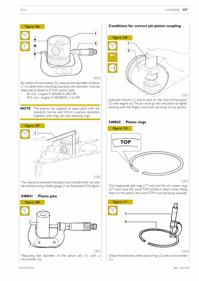
By means of micrometer (2), measure the diameter of piston(1) to determine mounting clearance; the diameter must bedetected at distance X from piston base:- 46 mm - engine F1AE0481A (96 HP)- 45.5 mm - engine F1AE0481B (116 HP).
The clearance between the piston and cylinder liner can alsobe checked using a feeler gauge (1) as illustrated in the figure.
540841 Piston pins
18857
Figure 108
Measuring the diameter of the piston pin (1) with amicrometer (2).
75397
Figure 109
Conditions for correct pin-piston coupling
Lubricate the pin (1) and its seat on the hubs of the piston(2) with engine oil. The pin must go into the piston by lightlypressing with the fingers and must not drop out by gravity.
74947
The trapezoidal split rings (1st slot) and the oil scraper rings(2nd slot) have the word TOP etched in them; when fittingthem on the piston, the word TOP must be facing upwards.
540842 Piston rings
Figure 110
16552
Figure 111
Check the thickness of the piston rings (2) with amicrometer(1).
1
2
The pistons are supplied as spare parts with thestandard, normal and 0.4mm oversize diameterstogether with rings, pin and retaining rings.
NOTE
F1A ENGINE 357DAILY
Base - May 2004Print 603.93.281
74948
41104
Figure 112
Figure 113
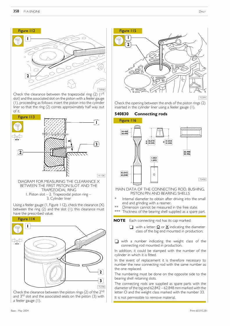
Check the clearance between the trapezoidal ring (2) (1stslot) and the associated slot on the piston with a feeler gauge(1), proceeding as follows: insert the piston into the cylinderliner so that the ring (2) comes approximately half way outof it.
DIAGRAM FOR MEASURING THE CLEARANCE XBETWEEN THE FIRST PISTON SLOT AND THE
TRAPEZOIDAL RING1. Piston slot � 2. Trapezoidal piston ring �
3. Cylinder liner
Using a feeler gauge (1, Figure 112), check the clearance (X)between the ring (2) and the slot (1); this clearance musthave the prescribed value.
75398
Figure 114
Check the clearance between the piston rings (2) of the 2ndand 3rd slot and the associated seats on the piston (3) witha feeler gauge (1).
75400
75399
Figure 115
Figure 116
Check the opening between the ends of the piston rings (2)inserted in the cylinder liner using a feeler gauge (1).
MAIN DATA OF THE CONNECTING ROD, BUSHING,PISTON PIN AND BEARING SHELLS
* Internal diameter to obtain after driving into the smallend and grinding with a reamer.
** Dimension cannot be measured in the free state.*** Thickness of the bearing shell supplied as a spare part.
540830 Connecting rods
- with a number indicating the weight class of theconnecting rod mounted in production.
In addition, it could be stamped with the number of thecylinder in which it is fitted.In the event of replacement it is therefore necessary tonumber the new connecting rod with the same number asthe one replaced.The numbering must be done on the opposite side to thebearing shell retaining slots.The connecting rods are supplied as spare parts with thediameter of the big end 62.842 � 62.848 mmmarked with theletter O and the weight class marked with the number 33.It is not permissible to remove material.
Each connecting rod has its cap marked:
- with a letter: O or X indicating the diameterclass of the big end mounted in production;
NOTE
F1A ENGINE DAILY358
Base - May 2004 Print 603.93.281
Figure 117
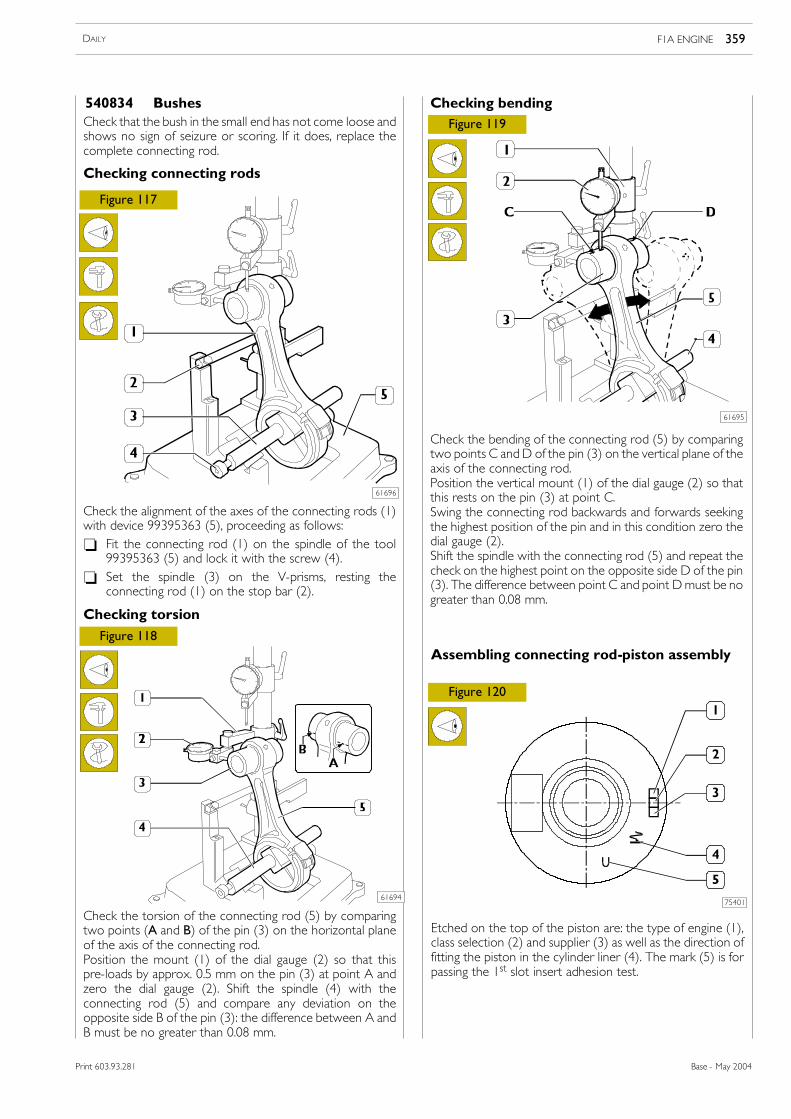
Check that the bush in the small end has not come loose andshows no sign of seizure or scoring. If it does, replace thecomplete connecting rod.
540834 Bushes
Checking connecting rods
61696
Check the alignment of the axes of the connecting rods (1)with device 99395363 (5), proceeding as follows:- Fit the connecting rod (1) on the spindle of the tool
99395363 (5) and lock it with the screw (4).- Set the spindle (3) on the V-prisms, resting the
connecting rod (1) on the stop bar (2).
Figure 118
Check the torsion of the connecting rod (5) by comparingtwo points (A and B) of the pin (3) on the horizontal planeof the axis of the connecting rod.Position the mount (1) of the dial gauge (2) so that thispre-loads by approx. 0.5 mm on the pin (3) at point A andzero the dial gauge (2). Shift the spindle (4) with theconnecting rod (5) and compare any deviation on theopposite side B of the pin (3): the difference between A andB must be no greater than 0.08 mm.
Checking torsion
61694
Checking bending
Check the bending of the connecting rod (5) by comparingtwo points C andD of the pin (3) on the vertical plane of theaxis of the connecting rod.Position the vertical mount (1) of the dial gauge (2) so thatthis rests on the pin (3) at point C.Swing the connecting rod backwards and forwards seekingthe highest position of the pin and in this condition zero thedial gauge (2).Shift the spindle with the connecting rod (5) and repeat thecheck on the highest point on the opposite side D of the pin(3). The difference between point C and point Dmust be nogreater than 0.08 mm.
61695
Figure 119
Etched on the top of the piston are: the type of engine (1),class selection (2) and supplier (3) as well as the direction offitting the piston in the cylinder liner (4). The mark (5) is forpassing the 1st slot insert adhesion test.
75401
Assembling connecting rod-piston assembly
Figure 120
F1A ENGINE 359DAILY
Base - May 2004Print 603.93.281
75402
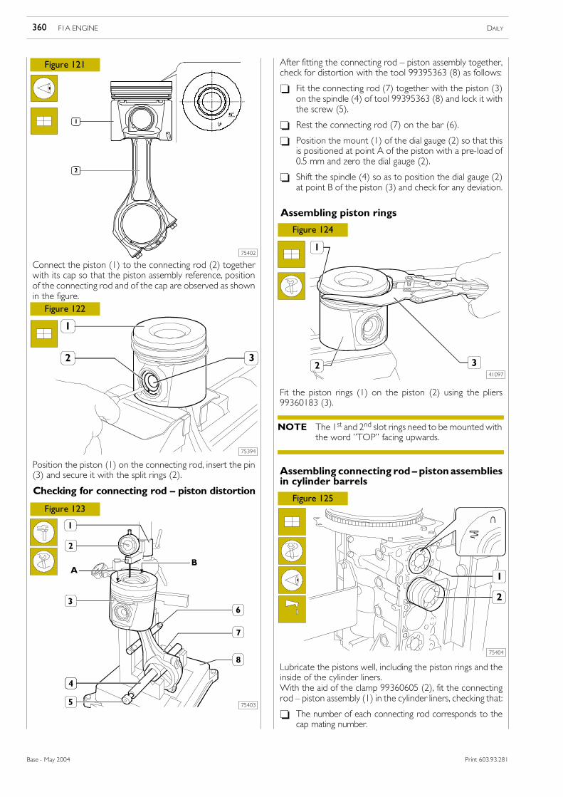
Connect the piston (1) to the connecting rod (2) togetherwith its cap so that the piston assembly reference, positionof the connecting rod and of the cap are observed as shownin the figure.
Position the piston (1) on the connecting rod, insert the pin(3) and secure it with the split rings (2).
Figure 121
Figure 122
75394
Figure 123
Checking for connecting rod � piston distortion
75403
After fitting the connecting rod � piston assembly together,check for distortion with the tool 99395363 (8) as follows:
- Fit the connecting rod (7) together with the piston (3)on the spindle (4) of tool 99395363 (8) and lock it withthe screw (5).
- Rest the connecting rod (7) on the bar (6).
- Position the mount (1) of the dial gauge (2) so that thisis positioned at point A of the piston with a pre-load of0.5 mm and zero the dial gauge (2).
- Shift the spindle (4) so as to position the dial gauge (2)at point B of the piston (3) and check for any deviation.
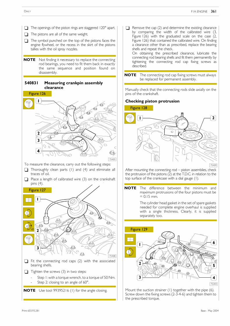
Figure 124
Assembling piston rings
Fit the piston rings (1) on the piston (2) using the pliers99360183 (3).
Lubricate the pistons well, including the piston rings and theinside of the cylinder liners.With the aid of the clamp 99360605 (2), fit the connectingrod � piston assembly (1) in the cylinder liners, checking that:
- The number of each connecting rod corresponds to thecap mating number.
The 1st and 2nd slot rings need to be mounted withthe word �TOP� facing upwards.
NOTE
F1A ENGINE DAILY360
Base - May 2004 Print 603.93.281
- Fit the connecting rod caps (2) with the associatedbearing shells.
- Tighten the screws (3) in two steps:
- Step 1: with a torque wrench, to a torque of 50 Nm.- Step 2: closing to an angle of 60°.
Figure 126
- The openings of the piston rings are staggered 120° apart.
- The pistons are all of the same weight.
- The symbol punched on the top of the pistons faces theengine flywheel, or the recess in the skirt of the pistonstallies with the oil spray nozzles.
540831 Measuring crankpin assemblyclearance
75405
To measure the clearance, carry out the following steps:- Thoroughly clean parts (1) and (4) and eliminate all
traces of oil.- Place a length of calibrated wire (3) on the crankshaft
pins (4).
75408
Figure 127
α
- Remove the cap (2) and determine the existing clearanceby comparing the width of the calibrated wire (3,Figure 126) with the graduated scale on the case (2,Figure 126) that contained the calibrated wire. On findinga clearance other than as prescribed, replace the bearingshells and repeat the check.On obtaining the prescribed clearance, lubricate theconnecting rod bearing shells and fit them permanently bytightening the connecting rod cap fixing screws asdescribed.
Manually check that the connecting rods slide axially on thepins of the crankshaft.
75409
Figure 128
Checking piston protrusion
After mounting the connecting rod � piston assemblies, checkthe protrusion of the pistons (2) at the T.D.C. in relation to thetop surface of the crankcase with a dial gauge (1).
75283
Figure 129
Mount the suction strainer (1) together with the pipe (6).Screw down the fixing screws (2-3-4-6) and tighten them tothe prescribed torque.
Not finding it necessary to replace the connectingrod bearings, you need to fit them back in exactlythe same sequence and position found ondisassembly.
NOTE
Use tool 99395216 (1) for the angle closing.NOTE
The connecting rod cap fixing screws must alwaysbe replaced for permanent assembly.
NOTE
The difference between the minimum andmaximum protrusions of the four pistons must be= 0.15 mm.
The cylinder head gasket in the set of spare gasketsneeded for complete engine overhaul is suppliedwith a single thickness. Clearly, it is suppliedseparately too.
NOTE
F1A ENGINE 361DAILY
Base - May 2004Print 603.93.281
75410
75411
75412
75413
Figure 130
Figure 131
Figure 132
Figure 133
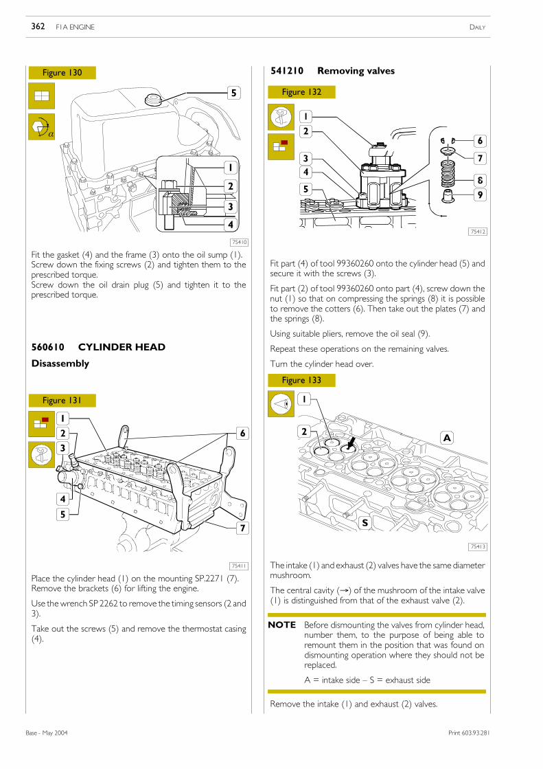
Fit the gasket (4) and the frame (3) onto the oil sump (1).Screw down the fixing screws (2) and tighten them to theprescribed torque.Screw down the oil drain plug (5) and tighten it to theprescribed torque.
Place the cylinder head (1) on the mounting SP.2271 (7).Remove the brackets (6) for lifting the engine.
Use thewrench SP 2262 to remove the timing sensors (2 and3).
Take out the screws (5) and remove the thermostat casing(4).
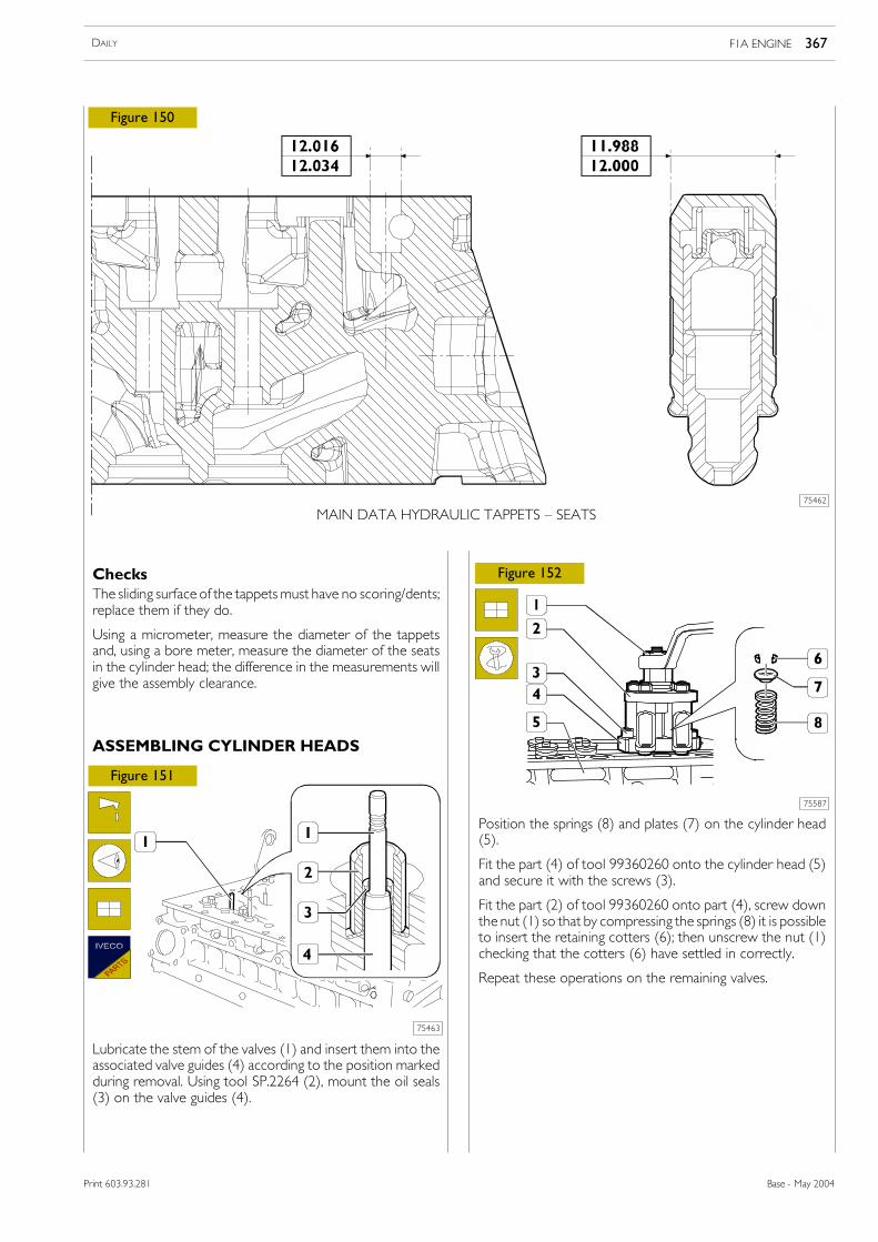
Fit part (4) of tool 99360260 onto the cylinder head (5) andsecure it with the screws (3).
Fit part (2) of tool 99360260 onto part (4), screw down thenut (1) so that on compressing the springs (8) it is possibleto remove the cotters (6). Then take out the plates (7) andthe springs (8).
Using suitable pliers, remove the oil seal (9).
Repeat these operations on the remaining valves.
Turn the cylinder head over.
The intake (1) and exhaust (2) valves have the same diametermushroom.
The central cavity (→) of the mushroom of the intake valve(1) is distinguished from that of the exhaust valve (2).
α
560610 CYLINDER HEAD
Disassembly
541210 Removing valves
Remove the intake (1) and exhaust (2) valves.
Before dismounting the valves from cylinder head,number them, to the purpose of being able toremount them in the position that was found ondismounting operation where they should not bereplaced.
A = intake side � S = exhaust side
NOTE
F1A ENGINE DAILY362
Base - May 2004 Print 603.93.281
Print 603.43.351
75451
75452
18625
18882
Figure 134
Figure 135
Figure 136
Figure 137
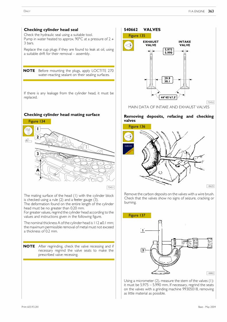
The mating surface of the head (1) with the cylinder blockis checked using a rule (2) and a feeler gauge (3).The deformation found on the entire length of the cylinderhead must be no greater than 0.20 mm.For greater values, regrind the cylinder head according to thevalues and instructions given in the following figure.
The nominal thickness A of the cylinder head is 112 ±0.1mm;the maximum permissible removal of metal must not exceeda thickness of 0.2 mm.
Checking cylinder head sealCheck the hydraulic seal using a suitable tool.Pump in water heated to approx. 90°C at a pressure of 2 ÷3 bars.
Replace the cup plugs if they are found to leak at oil, usinga suitable drift for their removal � assembly.
Checking cylinder head mating surface
If there is any leakage from the cylinder head, it must bereplaced.
MAIN DATA OF INTAKE AND EXHAUST VALVES
Remove the carbon deposits on the valves with a wire brush.Check that the valves show no signs of seizure, cracking orburning.
540662 VALVES
Removing deposits, refacing and checkingvalves
Using a micrometer (2), measure the stem of the valves (1):it must be 5.975 � 5.990 mm. If necessary, regrind the seatson the valves with a grinding machine 99305018, removingas little material as possible.
EXHAUSTVALVE
INTAKEVALVE
Before mounting the plugs, apply LOCTITE 270water-reacting sealant on their sealing surfaces.
NOTE
After regrinding, check the valve recessing and ifnecessary regrind the valve seats to make theprescribed valve recessing.
NOTE
F1A ENGINE 363DAILY
Base - May 2004Print 603.93.281
75453
75455
75456
75457
Figure 138
Figure 139
Figure 140
Figure 141
Figure 142
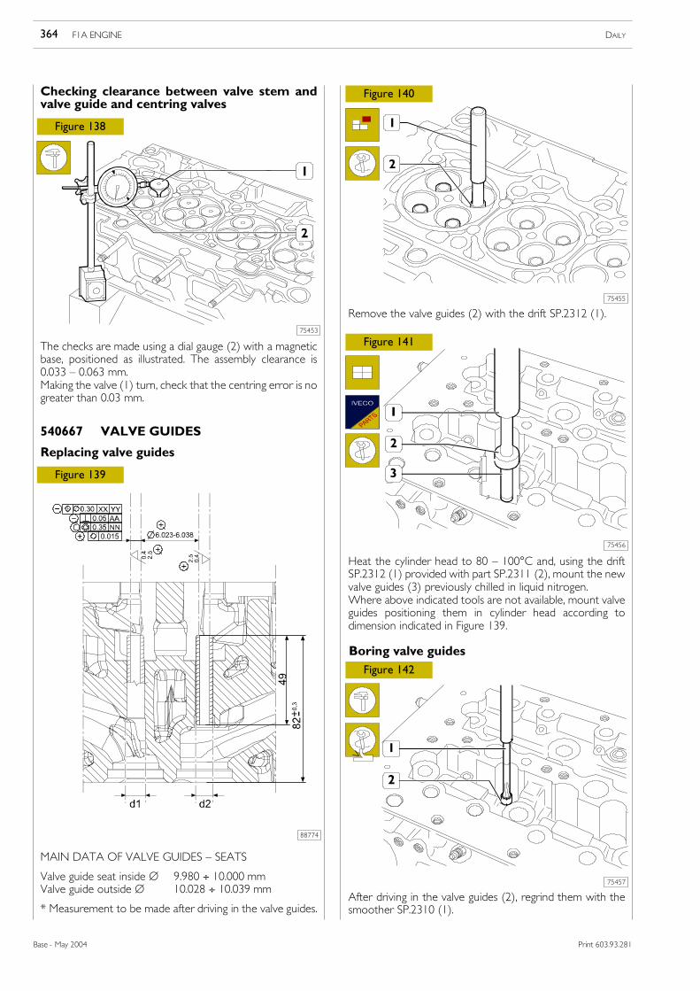
The checks are made using a dial gauge (2) with a magneticbase, positioned as illustrated. The assembly clearance is0.033 � 0.063 mm.Making the valve (1) turn, check that the centring error is nogreater than 0.03 mm.
* Measurement to be made after driving in the valve guides.
Remove the valve guides (2) with the drift SP.2312 (1).
Heat the cylinder head to 80 � 100°C and, using the driftSP.2312 (1) provided with part SP.2311 (2), mount the newvalve guides (3) previously chilled in liquid nitrogen.Where above indicated tools are not available, mount valveguides positioning them in cylinder head according todimension indicated in Figure 139.
After driving in the valve guides (2), regrind them with thesmoother SP.2310 (1).
Checking clearance between valve stem andvalve guide and centring valves
540667 VALVE GUIDES
Replacing valve guides
Boring valve guides
88774
F1A ENGINE DAILY364
Base - May 2004 Print 603.93.281
Print 603.43.351
75459
75458
54760
Figure 143
Figure 144
Figure 145
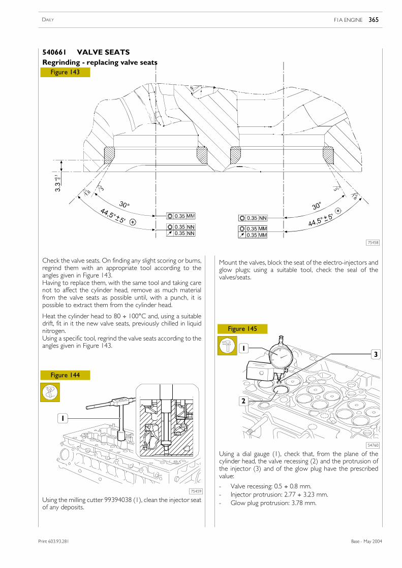
Check the valve seats. On finding any slight scoring or burns,regrind them with an appropriate tool according to theangles given in Figure 143.Having to replace them, with the same tool and taking carenot to affect the cylinder head, remove as much materialfrom the valve seats as possible until, with a punch, it ispossible to extract them from the cylinder head.
Heat the cylinder head to 80 ÷ 100°C and, using a suitabledrift, fit in it the new valve seats, previously chilled in liquidnitrogen.Using a specific tool, regrind the valve seats according to theangles given in Figure 143.
Using the milling cutter 99394038 (1), clean the injector seatof any deposits.
Mount the valves, block the seat of the electro-injectors andglow plugs; using a suitable tool, check the seal of thevalves/seats.
Using a dial gauge (1), check that, from the plane of thecylinder head, the valve recessing (2) and the protrusion ofthe injector (3) and of the glow plug have the prescribedvalue:
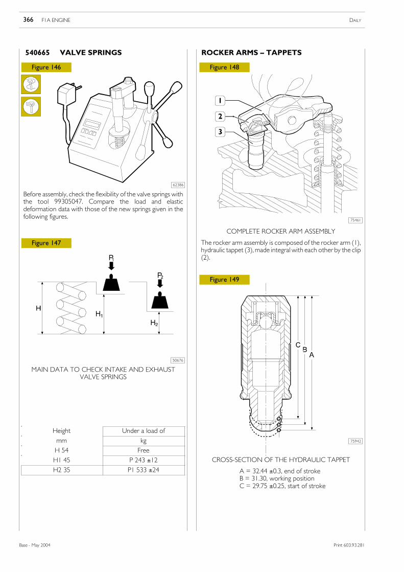
Before assembly, check the flexibility of the valve springs withthe tool 99305047. Compare the load and elasticdeformation data with those of the new springs given in thefollowing figures.
MAIN DATA TO CHECK INTAKE AND EXHAUSTVALVE SPRINGS
COMPLETE ROCKER ARM ASSEMBLY
The rocker arm assembly is composed of the rocker arm (1),hydraulic tappet (3),made integral with each other by the clip(2).
540665 VALVE SPRINGS ROCKER ARMS � TAPPETS
CROSS-SECTION OF THE HYDRAULIC TAPPET
A = 32.44 ±0.3, end of strokeB = 31.30, working positionC = 29.75 ±0.25, start of stroke
F1A ENGINE DAILY366
Base - May 2004 Print 603.93.281
Print 603.43.351
Height Under a load of
mm kg
H 54 Free
H1 45 P 243 ±12
H2 35 P1 533 ±24
75463
75462
75587
Figure 150
Figure 151
Figure 152ChecksThe sliding surface of the tappetsmust have no scoring/dents;replace them if they do.
Using a micrometer, measure the diameter of the tappetsand, using a bore meter, measure the diameter of the seatsin the cylinder head; the difference in the measurements willgive the assembly clearance.
Lubricate the stem of the valves (1) and insert them into theassociated valve guides (4) according to the position markedduring removal. Using tool SP.2264 (2), mount the oil seals(3) on the valve guides (4).
MAIN DATA HYDRAULIC TAPPETS � SEATS
Position the springs (8) and plates (7) on the cylinder head(5).
Fit the part (4) of tool 99360260 onto the cylinder head (5)and secure it with the screws (3).
Fit the part (2) of tool 99360260 onto part (4), screw downthe nut (1) so that by compressing the springs (8) it is possibleto insert the retaining cotters (6); then unscrew the nut (1)checking that the cotters (6) have settled in correctly.
Repeat these operations on the remaining valves.
ASSEMBLING CYLINDER HEADS
F1A ENGINE 367DAILY
Base - May 2004Print 603.93.281
75464
75465
75466
75467
75468
Figure 153
Figure 154
Figure 155
Figure 156
Figure 157
Fit the thermostat casing (5) with a new seal and tighten thefixing screws (4) to the prescribed torque.
Mount temperature sensors (1 and 2), and tighten them atprescribed torque.
For tightening sensor (2), use wrench SP.2262 (3).
Mount the temperature sensors (1 and 2) and, using thewrench SP.2263 (3), tighten them to the prescribed torque.
Position the overhead (2) together with the pins 99360614(1) on the mounting SP. 2271.
Take out the screw (4) with the washer (5) beneath fasteningthe toothed pulley (3).
Using the extractor 99340028 (2) extract the toothed pulley(1) driving the camshaft.
Using four self-tapping screws (2), apply the tool SP. 2325 (3)to the seal (1) and with the extractor (5 and 6) remove theseal (1) from the overhead (4).
Remove the circlip (1) and take off the cover (2) togetherwith the seal (3).
540650 Overhead
Overhead removal
The screws (2) must be screwed down so they getpositioned at the dimension shown in the figure.
NOTE
F1A ENGINE DAILY368
Base - May 2004 Print 603.93.281
Print 603.43.351/D
1. Camshaft on intake side � 2. Hydraulic tightener �3. Camshaft on exhaust side � 4. MORSE chain �5. Rocker arms � 6. Hydraulic reacting tappet �
7. Valve assembly.
DescriptionThe timing system is the typewith a twin camshaft in theheadand four valves per cylinder with hydraulic tappets.Motion is transmitted by the crankshaft, via a toothed belt,to the gear keyed onto the intake valve drive shaft. The drivetransmission of the exhaust valve drive shaft takes place viaa MORSE-type chain kept under tension by a hydraulictightener.The toothed belt, moreover, drives the water pump and thehigh-pressure pump CP3 and is kept at the right tension byan automatic tightener roller.The four valves move by the action of the �free� rocker arms(with no supporting shaft).The rocker arms, one per valve, are always in contact withthe corresponding cam and are kept in this position by ahydraulic reacting tappet, thereby eliminating the need forperiodical adjustment.
75469
75471
75470
75472
75473
Figure 158
Figure 159
Figure 160
Figure 161
Figure 162
Take out the screws (1) and remove the rear cover (2)together with its gasket.
Insert a suitable pin (2) in the hole (⇒) of the chain drive (3).Take out the screws (4) and (6) with their washers (5) forfixing gears to the camshafts.Take out the screws (7) and remove the chain drive (3) fromthe overhead (1).
Turn over the overhead (1) and, taking care not to damagethe seats, extract the camshafts (2) and (3) from it.
TIMING SYSTEM DIAGRAM
5412 TIMING SYSTEM
1
2
3
1 CLOSINGINTAKEOPENING
2 CLOSINGEXHAUSTOPENING
3 FIRINGORDER1-3-4-2
T.D.C.
B.D.C.
F1A ENGINE 369DAILY
Base - May 2004Print 603.93.281
75474 75475
75476
Figure 163
Figure 164
Figure 165
Using a micrometer (1), measure the diameter of the pins (2)of the camshaft and, using a bore meter, measure thediameter of the supporting seats in the overhead.The difference between these two measurements gives theexisting clearance.The nominal assembly clearance is 0.037 ÷ 0.088 mm.
541210 CamshaftChecksThe surfaces of the shaft supporting pins and of the camsmust be finely honed; if there is any sign of meshing orscoring, replace the shaft.
541211 Checking cam lift and pin alignment
Set the shaft (1) on tailstocks and, using a dial gauge on themiddlemounting, check that the alignment error is no greaterthan 0.04 mm; replace the shaft if it is. In addition, check thecam lift: it must be as prescribed; replace the shaft if it is anydifferent.
Lubricate the supporting pins of the shafts (2 and 3) and fitthem in the overhead (1).
Position the overhead (1) and secure it on the mountingSP.2271 (2).Position the camshafts (4 and 5) so as to be able to insert thepins 99360614 (3) into their radial holes through thethreaded holes of the overhead.
Compress the tightener so as to be able to insert a suitablepin (2) into the hole (→) of the chain drive (1).
Fit the chain drive (2) on the camshafts and secure it to theoverhead (1) tightening the screws (8) to the prescribedtorque.
Screw down the screws (4) and (7) with the washers (5) and(6) and tighten them as follows:
- Tighten the screw (7) to a torque of 50 Nm.
- Close further with an angle of 60°.
- Take out the pin (5).
- Tighten the screw (4) to a torque of 50 Nm.
- Close further with an angle of 60°.
Fit on the rear cover (2) with a new gasket and tighten thefixing screws (1) to the prescribed torque.
α
In this operation, take care not to damage theoverhead supporting seats.
NOTE
Use the goniometer 99395216 for the angleclosing.
NOTE
F1A ENGINE 371DAILY
Base - May 2004Print 603.93.281
Print 603.43.351
Assembling overhead
75468
75482
75481
75281
75483
Figure 171
Figure 172
Figure 173
Figure 174
Figure 175
Fit a new seal (3) on the cover (2) and fit this in the overhead.
Fit on the seal (1).
Lubricate the shank of the camshaft.
Using the keying device 99374458 (3), fit the seal (2) in theoverhead (1).
Fit the toothed pulley (1) onto the camshaft so as to align thehole of the pulley with that of the overhead and insert thetool 99360608 (4) into these holes. Screw down the screw(3) together with the washer (2) without tightening fully.
Fit the oil pressure control valve (1) in the crankcase.
Fit on the plug (2) with the seal (3) and tighten it to theprescribed torque.
Fit the centring tool 99396037 (2) onto the shank of thecrankshaft.
Mount the oil vacuum pump assembly (1) with a new gasketand tighten the screws (1-15) according to the followingprocedures:
- Tighten the screws from no. 1 to no. 6 to a torque of 5±1 Nm while checking that the tool 99360037 (2) turnsfreely.
- Tighten the screws from no. 7 to no. 15 to a torque of10 ±1 Nm.
- Tighten the screws from no. 1 to no. 6 to a torque of 10±1 Nm.
- After checking that tool 99360037 (2) turns freely,remove it.
540442 Assembling front seal ring
The toothed pulley (1, Figure 173) is not locked onthe shaft since it must be able to turn when fittingand tensioning the timing belt. For the same reason,keep the tools 99360608 (4, Figure 173) and99360614 (3, Figure 167) fitted.
NOTE
F1A ENGINE DAILY372
Base - May 2004 Print 603.93.281
Lubricate the shank of the crankshaft.
Screw down part (3) of tool 99346254 in the crankshaft andplace the seal (2) on the part (3).
Key part (5) of tool 99346254 onto part (3), screw down thenut (4) until the seal (2) gets into position in the seat of theoil vacuum pump assembly (1).
Take out the tool 99346254 (3, 4 and 5).
75484
75485
75280
75279
75486
Figure 176
Figure 177
Figure 178
Figure 179
Figure 180
Turn the crankshaft so as to be able to insert tool 99360615(5) into the hole in the crank of the crankshaft, through thehole in the oil vacuumpump assembly (1), to block crankshaftrotation.
Mount the gear (2), screw down the screw (3) together withthe spacer (4) and tighten it to the prescribed torque.
Mount the speed sensor (1) with a fresh gasket and tightenthe fixing screw (2) to the prescribed torque (if applicable).
Fit on the compressor mounting (3) and tighten the fixingscrews (4) to the prescribed torque.
Mount the air-conditioner compressor (1) (if applicable) andtighten its fixing (2) screws to the prescribed torque.
Mount the oil pressure transmitter (3) with a fresh gasket.
Mount the heat exchanger (1) with a fresh seal and tightenthe coupling (2) to the prescribed torque.
Do not remove the tool 99360615 (5) as it will beneeded for fitting the timing drive belt.
NOTE
F1A ENGINE 373DAILY
Base - May 2004Print 603.93.281
Print 603.43.351/D
75487
75489
75488
75490
75271
Figure 181
Figure 182
Figure 183
Figure 184
Figure 185
Lubricate the seal of the oil filter (1) with engine oil.Using tool 99360076 (2), tighten the oil filter to theprescribed torque.
Thoroughly clean the mating surface (à) of the water pump(1) and position fresh seals (2 and 3) on it.
Mount the water pump (1) and tighten the fixing screws (2)to the prescribed torque.
Fit the high-pressure pump (2) onto the flange of the waterpump (1) and tighten the fixing screws (3) to the prescribedtorque.
Fit the driving gear (1) onto the shaft of the high-pressurepump and block rotation of this shaft by applying toolSP.2263 (2) as illustrated in the figure. Tighten the nut (3) tothe prescribed torque and remove the tool (2).
F1A ENGINE DAILY374
Base - May 2004 Print 603.93.281
Print 603.43.351
75491
75492
75493
75494
Figure 186
Figure 187
Figure 188
Figure 189
Check that tool 99360619 (2) inserted in the hole (→) of theoil vacuum pump assembly (1) blocks crankshaft rotation.
This condition is necessary for setting up the timing systemand to prevent the valves interfering with the pistons.
Check that the mating surfaces of the cylinder head andcrankcase are clean.Keep the cylinder head gasket clean.Position the cylinder head gasket (1) of the thicknessdetermined under the heading �checking piston protrusion�with the lettering �TOP� facing the cylinder head.
Mount the cylinder head (1).
Screw down the fixing screws (3) and tighten them, in threesuccessive stages, following the order andmethods shown inthe following figure.
Diagram of the tightening sequence for the cylinder headfixing screws:
- 1st phase: pre-tightening with torque wrench• screws 1-2-3-4-5-6 to a torque of 100 ±5 Nm;• screws 7-8-9-10 to a torque of 50 ±2.5 Nm.
It is essential to keep the gasket sealed in its packageuntil just before assembly.
NOTE
The angle closure is done with tool 99395216 (2).NOTE
F1A ENGINE 375DAILY
Base - May 2004Print 603.93.281
Refitting cylinder head
75495
75497
75496
Figure 190
Figure 191
Figure 192
Figure 193
Thoroughly clean the hydraulic tappets (2), lubricate them andfit them in the cylinder head (3), positioning the rocker arms (1)on the valves correctly.Fit on the gasket (5).Insert the two tools SP. 2264 (4) into the electro-injector seatsfor subsequent centring of the overhead on the cylinder head.
Mount the overhead (1) together with the tools 99360614(3) for the timing and tighten the fixing screws (2) to theprescribed torque.
Take out the tools SP. 2264 (4).
Mount the fixed tightener (1) and tighten the fixing screw (2)to the prescribed torque.
Mount the automatic tightener (4) without fully tighteningthe fixing screw (3), max. closing torque 5 Nm.
Turn the automatic tightener (1) clockwise, positioning it asshown in frame A.Turn the timing belt (10) as shown in the figure observing theprecautions below.Do not bend the timing belt. Arrows indicating the directionof assembly of the timing belt on the engine are shown onthe back of the belt. The arrows must correspond to thedirection of rotation of the belt and the notches mustcoincide with those on the pulley (7) and the gear (12).If required to fit the timing belt (10) on the pulley (7), removetool 99360608 (8) and turn the pulley (7) clockwise by nomore than half a pulley tooth.
On completing assembly, adjust the toothed pulley (7) to putthe section X of the belt under tension and tighten the screw(9) to a torque of 90 NmKeeping the screw (2) stationary and using a suitable wrenchon the hexagon of the plate (3) of the tightener, turn itanticlockwise to cover the reference hole (5) located on thefixed portion of the tightener (see frame B).In the above conditions, tighten the fixing screw (2) to atorque of 36 ± 4 NmRemove the tools 99360614 (6) and 99360615 (11) for thetiming.Turn the engine in its direction of rotation by 8 turns to beable to put the tools (6) and (11) back in to do the timing.In these conditions, the notches of the timing belt (10) mustcoincide with those of the pulley (7) and the gear (12).
X = Direction of movement of the tightener �Y = Direction of rotation of the key.
85844a
If the engine has run for a period equivalent to ≥25,000 km, the toothed belt must be replaced witha fresh one, no matter what its state of wear.
NOTE
Do not turn the engine in the opposite direction;if, on turning the engine, you pass the point forinserting the tools (6) and (11), turn the engineclockwise by another two turns.
NOTE
F1A ENGINE DAILY376
Base - May 2004 Print 603.93.281
Print 603.43.351
See frame C: Figure 193, holding the tightener plate (3)stationary with the wrench inserted in its hexagon, loosenthe fixing screw (2). Keeping the fixing screw (2) stationary,turn the plate (3) clockwise until its reference mark (4)coincides with the reference hole (5) of the fixed portion ofthe tightener. In the above conditions, tighten the screw (2)to a torque of 36 ±4 Nm.After assembly, the belt (10) tension measured using tool99395849must be as follows in the following points: X = 212± 12 Hz -X1 = 178 ± 10 Hz.
75499
75500
Figure 194
Figure 195
Remove the tools (6 and 11, Figure 193).
Screw the plug (1) into the oil-vacuum pump mounting (2)and the plugs on the holes of the overhead.
Mount the timing cover (1) and tighten the screws (2) to theprescribed torque.
Mount the damper pulley (3) and tighten the screws (4) tothe prescribed torque.
76252
Figure 196
Fit on the mounting (1) together with the electromagneticcoupling (4) and tighten the fixing screws (2 and 3) to theprescribed torque.
75251
75250
Figure 197
Figure 198
Mount the oil level sensor (1).
Fit on the power steering (2) pump mounting (4) and tightenthe fixing screws (3) to the prescribed torque.
Position the alternator (2) on the mounting (5) and secureit with the bottom screws (3 and 4) and the bolt.
F1A ENGINE 377DAILY
Base - May 2004Print 603.93.281
Print 603.43.351/D
75248
75502
75503
Figure 199
Figure 200
Figure 201
Figure 202
Using a wrench on the automatic tightener (2), mount thedrive belt (1), taking care to position its ribs correctly in therespective races of the pulleys.
Fit the tightener (1) without tightening the screw (4).Fit the drive belt (5) taking care to position its ribs correctlyin the respective races of the pulleys.
Fit a new seal (3) on the electro-injector (1) and mount thisin the overhead (2).
544035 Adjusting air-conditioner �compressor drive belt tension
With tool SP. 2341 (2) inserted in the holes of the tightener(1) and torque wrench (3), turn the tightener (1) with atorque of 8.2 � 10 Nm; in this condition, tighten the screw(4) to a torque of 25 Nm.
Turn the engine in its direction of rotation to have the belt(5) make two full turns.
With appliance 99395849, measure the tension of the belt(5) in section A, which must be 204 ±10 Hz correspondingto a load on the tightener of 1010 ± Nm.
In the case of engines with a compressor drive belt of elastictype, no tensioning is needed. For mounting, operate asfollows.
75501
Mount the fixed tightener (2) and tighten the fixing screw (1).
Mount the automatic tightener (3) and tighten the screw (4)to the prescribed torque.
90155
Fit the flexible belt (3) equipped with tool 99360191 (2) onthe pulley (4) and apply the tool on the pulley (1).Fit the drive ring (5) on the flexible belt (3) and fasten the ringon the compressor support.Turn the drive shaft clockwise until the belt fits perfectly onthe pulley (1).
Figure 203
The elastic belt must be replaced by a new elasticbelt at each dismounting operation.
NOTE
F1A ENGINE DAILY378
Base - May 2004 Print 603.93.281
75506
75508
75509
Figure 204
Figure 205
Connect the fuel pipes (2) to the electro-injectors (1) and tothe hydraulic accumulator (3).Tighten the screws (4) fixing the electro-injector brackets tothe prescribed torque.
Mount the glow plugs (1) and, using the box-type wrench SP.2275 (2) and torque wrench 99389819 (3), tighten them toa torque of 8 ÷ 10 Nm.
Mount the intake manifold (1) with a new gasket and, usinga torque wrench (3), tighten the fixing screws (2) to theprescribed torque.
75507
Figure 206
Using the wrench (4) of the 99317915 series and the torquewrench 99389829 (3), tighten the fuel pipe fittings (1) and (2)to the prescribed torque.
88615
Forged version: on hydraulic accumulator (2), mount:pressure sensor (1) tightening it at 35 ± 5 Nm torque, andpressure relief valve (3) tightening it at 27 ± 2 Nm torque.Welded version: mount pressure sensor and tighten it at 70± 5 Nm torque.
Figure 207
75504
Mount the brackets (3) fastening the electro-injectors (1)and screw down the screws (2) without locking them.Mount the hydraulic accumulator (4) and tighten the fixingscrews to the prescribed torque.
Figure 208
Whenever they get removed, the fuel pipes mustbe replaced with new ones.
NOTE
Figure 209
F1A ENGINE 379DAILY
Base - May 2004Print 603.93.281
75510
75511
75256
75512
Figure 210
Figure 211
Figure 212
Figure 213
Connect the fuel pipe (4) to the hydraulic accumulator (7)and to the high-pressure pump (5).With wrench (2) of series 99317915 and dynamometricwrench 99389829 (1), tighten pipe fittings (3 and 6) atprescribed torque.
Connect the fuel recovery pipe (1) with new seals to thepressure relief valve (6) tightening the coupling (7) to theprescribed torque (only for forged version hydraulicaccumulator).Connect the fuel recovery pipes (1) and (5) with new sealsto the high-pressure pump (2) with the couplings (3) and (4).Insert the oil dipstick tube (9) with a new seal into thecrankcase and secure it together with the pipe (10), using thescrew (8) tightened to the prescribed torque, to the intakemanifold.
Press the clips (3) in the direction shown by the arrow andconnect the fuel recovery pipe fittings (1) to theelectro-injectors (2).
Fit the exhaust manifold (5) with a new gasket and thespacers (6) and tighten the nuts (7) to the prescribed torque.On the exhaust manifold (6), mount: the turbocharger (4)with a new gasket and tighten the nuts (3) with washers tothe prescribed torque, the compensator pipe (1) (ifapplicable) with a new seal and tighten the nuts (2) withwashers to the prescribed torque.
Whenever they get removed, the fuel pipes (4)must be replaced with new ones.
NOTE
Before fitting the turbocharger on the engine, it isnecessary to fill the central body with enginelubricating oil.
NOTE
F1A ENGINE DAILY380
Base - May 2004 Print 603.93.281
Print 603.43.351
7551375263
75255
Figure 214
Figure 215
Figure 216
Figure 217
Connect the pipe (4) to the cylinder head (6) and to theturbocharger (7).Using the wrench (2) in the 99317915 series and the torquewrench 99389829 (1), tighten the couplings (3 and 5) to theprescribed torque.
Connect the air duct (5) to the turbocharger (2) and to theoverhead (3).Tighten the clamp (1) and the screw (4) to the prescribedtorque.
For engines with E.G.R. onlyMount the flange (7) with a new gasket and tighten thescrews (8) to the prescribed torque.Mount the heat exchanger (1) together with the E.G.R. valve(5) and new gaskets and tighten the screws (2 and 6) to theprescribed torque.Connect the pipe (4) to the exchanger (1) and to the flange(7) securing it with the clamps (3).
Mount the oil fillpipe (5) with a new seal and tighten the nuts(6) to the prescribed torque.Mount the coalescence filter (3) and tighten its fixing nuts (4)to the prescribed torque.Mount the bracket (1) and tighten the screws (2) to theprescribed torque.
75264
F1A ENGINE 381DAILY
Base - May 2004Print 603.93.281
Print 603.43.351/D
75246
75245 75514
Figure 218
Figure 219
Figure 220
Fit the cooling fan (1) back onto the electromagneticcoupling. Fit the arm 99360549 onto the engine lifting hooks.Hook the arm onto the hoist and remove the engine fromthe rotary stand (3). Take out the brackets 99361028 (2).
Complete engine assembly.Fit on the left and right engine mountings (3) and tighten thefixing screws to the prescribed torque.Connect the oil pipe (2) to the turbocharger (1) and to thecrankcase and tighten the fixing screws and the coupling ofthe oil pipe (2) to the prescribed torque.If applicable, mount the following parts:
- Engine cable, connecting its electrical connections to thethermostat temperature sensor, timing sensor, enginespeed sensor, pressure regulator, rail pressure sensorand intake manifold air pressure/temperature sensor.
- Hydraulic accumulator guard.
- Top soundproofing cover.
- Add the prescribed grade and quantity of lubricating oilto the engine.
The sensor gap is:
- 1 ±0.5 mm, between the camshaft pulley (2) and timingsensor (1).
- 1 mm, between the phonic wheel (4) and speed sensor(3).
The engine is lubricated by forced circulation performed by thefollowing parts:
- An oil gear pump is incorporated in an assembly that alsoincludes the vacuum pump (GPOD).
- A pressure control valve incorporated in the crankcase.
- A Modine-type heat exchanger with built-in safety valve.
- A double filtration oil filter with built-in safety valve.Operation (see Figure 221)Engine oil is drawn up from the sump by the oil pump (3)via the suction strainer (2) and delivered under pressure tothe heat exchanger (5) where it is cooled.The oil continues through the oil filter (6) and goes tolubricate the relevant parts through ducts or pipes.At the end of the lubrication cycle, the oil returns to thesump by gravity. The oil filter can be excluded by the safetyvalve built into it if it gets clogged. The heat exchanger isalso excluded by a safety valve if it gets clogged.In addition, the lubrication oil supplies the hydraulicautomatic tightener (7) of the camshaft drive (8).
Clearance between the crankshaft gear teeth and the oilpump drive gear 0.003 ÷ 0.2 mm.The assembly must not be overhauled; in the event ofdefective operation, it must be replaced.
75517
Figure 222
Figure 223
OIL VACUUM PUMP ASSEMBLY (GPOD)
The oil pump (3) is a gear pump driven directly by thecrankshaft.
CROSS-SECTION OF OIL PRESSURE CONTROLVALVE MOUNTED IN CRANKCASE
Valve removed from crankcase L = 51.75 mm.Valve fitted in crankcase L = 50.75 mm.Start of opening 4 bar L = 49.5maximum opening 4.6 bar L = 44.
75520
Figure 224
Figure 225
Figure 226
543070 Oil filter
75521
75523
Figure 227
PARTS COMPRISING THE OIL PRESSURECONTROL VALVE
1. Split ring � 2. Washer � 3. Spring � 4. Valve �5. Valve casing.
75522
MAIN DATA OF THE OIL PRESSURE CONTROLVALVE SPRING
Oil filter with single filtration with built-in by-pass valve �opening pressure 2.5 ± 0.3 bar.
543110 Modine heat exchanger
75524
Figure 228
Thoroughly clean the heat exchanger (1).Always change the seals (2 and 4).Built-in safety valve (3).Opening pressure 0.82 - 1.03 bar
543475 Oil pressure control valve
F1A ENGINE DAILY386
Base - May 2004 Print 603.93.281
Print 603.43.351
Figure 229540480 Oil vapour recirculation systemDescriptionThe oil vapours formed in the sump while the engine isrunning, passing through the overhead cover, are channelledinto the separator / condenser filter known as the blow-by.The filter is structured in two sections:
- The first one with a labyrinth, where most of the vapoursare condensed and return to the sump through anumbrella outlet valve.
- The second one includes a coalescence filter thatcondenses the remaining vapours that return to thesump through another umbrella valve.
The portion of vapour that has not condensed is sent, via aMANN-HUMMEL valve, to the intake duct and burnt duringnormal engine operation.
75525
OIL VAPOUR RECIRCULATION DIAGRAM
1. MANN-HUMMEL valve � 2. Umbrella valves � 3. Blow-by filter � A. Labyrinth � B. Intake oilvapour recovery flow � C. Oil return flow into sump � D. Flow of oil vapours from the sump �
E. Flow of oil vapours from the overhead � F. Coalescence filter.
The blow-by filter cannot be taken apart and musttherefore be replaced entirely.
NOTE
F1A ENGINE 387DAILY
Base - May 2004Print 603.93.281
Print 603.43.351
Figure 2305432 COOLINGDescriptionThe engine cooling system is the type with forced circulationin a closed circuit. It comprises the following parts:
- An expansion tank whose plug has two valvesincorporated in it: an outlet and an inlet, which governthe pressure of the system.
- A coolant level sensor at the base of the expansion tank.
- An engine cooling module to dissipate the heat takenfrom the engine by the coolant with a heat exchangerfor the intercooler.
- A heat exchanger to cool the lubricating oil.
- A heat exchanger to cool the exhaust gases (engineswith EGR).
- A centrifugal water pump incorporated in the crankcase.
- An electric fan comprising an electromagnetic couplingon whose shaft a hub turns idle that is fitted with anaxially mobile metal plate on which is mounted theimpeller.
- A 3-way thermostat governing the circulation of thecoolant.
OperationThe water pump driven by a poly-V belt by the crankshaftsends coolant into the crankcase andwith a greater head intothe cylinder head.When the coolant temperature reaches and exceeds theworking temperature, it causes the thermostat to open andthe fluid is channelled from here to the radiator and cooledby the fan.The pressure in the system due to the change in temperatureis governed by the outlet (2) and inlet (1) valves incorporatedin the expansion tank filler plug (detail A).The outlet valve (2) has a twofold function:
- to keep the system slightly pressurized so as to raise theboiling point of the coolant;
- to discharge into the atmosphere the excess pressureproduced in case of high coolant temperatures.
The function of the inlet valve (1) is to permit transferring thecoolant from the expansion tank to the radiator when alower pressure is created in the system due to the reductionin volume of the coolant as a result of its temperaturelowering.Outlet valve opening 1 ± 0.1 kg/cm2.Inlet valve opening 0.005 � 0.02 kg/cm2.
75526
Hot
Very hot
Cold
F1A ENGINE DAILY388
Base - May 2004 Print 603.93.281
CROSS-SECTION OF THE ELECTROMAGNETIC JOINT
CharacteristicsTransmissible torque at 20°C with clutch run in 45 NmVoltage 12 VoltsPower input 26 WThe electric fan control relay is activated or deactivatedaccording to the temperatures of: the engine coolant, the fuelsupercharging air and the pressure of the air conditioner fluid(if present).Coolant temperature(if the sensor is not defective)It activates at > 96°C and deactivates at < 84°C.Turbocharging air temperatureIt activates at > 75°C and deactivates at < 65°C.Fuel temperatures(if the coolant temperature sensor is acknowledged to bedefective by the EDC control unit)It activates at > 20°C and deactivates at < 10°C.With climate control systemWith pressure in the systemit turns on 18.5 ± 0.98 barit turns off 14.58 ± 0.98 bar
75527
Figure 231
Figure 232
Thewater pump (3) cannot be overhauled. In case of coolantleaking from the seal or damage, it must be replaced. Thewater pump casing (1) is also used as a mounting for thehigh-pressure pump. The seals (3 and 4) must always bereplaced.
75528
543212 Electromagnetic pulley
543210 Water pump
LONGITUDINAL CROSS-SECTION OF THEWATER PUMP
1. Pump casing � 2. Pump drive shaft together withbearing � 3. Seal � 4. Impeller.
Figure 233
75529
The by-pass thermostat (1) needs no adjustment.If there is any doubt about its operation, replace it.The thermostat casing is fitted with the thermometricswitch/transmitter and water temperature sensor.
A. � A1 Start of stroke at 78°C ±2°C.B. Valve (1) stroke at 94°C = 7 mm.B1 Valve (2) stroke 94°C, 6.4 mmThe stroke of 7 mm less than 60�.
543250 Thermostat
Figure 234
75530
F1A ENGINE 389DAILY
Base - May 2004Print 603.93.281
75531
Figure 235
TURBOCHARGING DIAGRAM
DescriptionThe turbocharging system comprises an air filter,turbocharger and intercooler.The air filter is the dry type comprising a filtering cartridge tobe periodically replaced.
The function of the turbocharger is to use the energy of theengine�s exhaust gas to send pressurized air to the cylinders.The intercooler comprises a radiator included in the enginecoolant radiator and its function is to lower the temperatureof the air leaving the turbocharger to send it to the cylinders.
HOT AIR AT ATMOSPHERIC TEMPERATURE
COLD EXHAUST GAS
HOT COMPRESSED AIR
COLD COMPRESSED AIR
EXHAUST GAS
F1A ENGINE DAILY390
Base - May 2004 Print 603.93.281
TURBOCHARGING
75532
Figure 236
A. THROTTLE VALVE SHUT
It is basically composed of:
- a central casing housing a shaft supported by bushings atwhose opposite ends are fitted the turbine wheel andthe compressor rotor;
- a turbine casing and a compressor casing mounted onthe end of the central body;
- an overpressure relief valve fitted on the turbine casing.Its function is to choke the exhaust gas outlet (detail B),sending a portion of the exhaust gas straight into theexhaust pipe when the turbocharging pressuredownstream from the turbocharger reaches the setting.
542410 Turbocharger
75533
B. THROTTLE VALVE OPEN
Figure 237
F1A ENGINE 391DAILY
Base - May 2004Print 603.93.281
75534
Figure 238
Figure 239
75535
Figure 240
75536
Cover the air, exhaust gas and lubricating oil inlets andoutlets. Thoroughly clean the outside of the turbochargerusing anticorrosive and antioxidant fluid. Disconnect the pipe(2) from the union of the pressure relief valve (1) and fit onit the pipe of the device 99367121 (1, Figure 239).
54249 Pressure relief valveChecking and adjusting pressure relief valve
Rest the tip of the dial gauge (1) with a magnetic base on theend of the tie rod (2) and zero it. Using the device 99367121(5), introduce compressed air into the valve casing (6) at theprescribed pressure and make sure this value stays constantthroughout the check; replace the valve if it doesn�t. In theabove conditions, the tie rodmust have made the prescribedtravel. On finding a different value, use the nuts (3 and 4).
Take off the nut (2).Take out the screws (5) and detach the bracket togetherwith the relief valve (7) from the turbocharger.Mount the new valve, performing the operations fordisassembly in reverse order, and register it as follows:Screw the nut (3) onto the stem (4) of the valve down to theend of the thread. Mount the lever (1) on the valve stem.Using device 99367121 (5, Figure 239), introducecompressed air into the valve (7) at the prescribed pressure;in this condition, screw down the nut (2) until the throttlevalve controlled by the lever (1) gets positioned in its seat.Unscrew the nut (3) to bring it into contact with the lever(1) and at the same time block the nuts (2 and 3).Adjust the pressure relief valve (7) as described under therelevant heading.Afterwards, paint the nuts (2 and 3) with safety paint andconnect the pipe (6) to the valve (7), securing it with a newretaining clamp.
Replacing pressure relief valveOn finding irregular engine operation due to theturbocharging system, it is first expedient toperform the checks on the turbocharger, check theefficiency of the seals and the fixing of the couplings,additionally checking there is no clogging in theintake sleeves, air filter or radiators. If theturbocharger damage is due to a lack of lubrication,check that the oil circulation pipes are not burst orclogged, in which case replace them or eliminatethe trouble.
NOTE
Before fitting the turbocharger on the engine, it isnecessary to fill the central body with enginelubricating oil.
NOTE
F1A ENGINE DAILY392
Base - May 2004 Print 603.93.281
REPAIRS
Figure 241
a. Brake booster vacuum circuit - b. EGR modulated vacuum circuit1. ECU - 2. High pressure pump - 3. Coolant temperature sensor - 4. Engine rpm sensor - 5. EGR pneumatic valve - 6. Flowmeter - 7. Suction air cleaner - 8. Modulating solenoid valve - 9. Air cleaner - 10. Vacuum brake booster -11. Reservoir - 12.
Vacuum unit.
Operating principlesThe ECU (MS6.3 or EDC 16) processes the data from theatmospheric pressure sensor, coolant sensor, engine rpmsensor, accelerator pedal potentiometer and controls themodulating solenoid valve via a PWM signal according toprogrammed settings.The control signal output by the ECU controls themodulating solenoid valve which puts the brake boostervacuum circuit into communication with that of the EGR.The vacuum created in the EGR circuit depends on thecontrol signal.The vacuum acts on the pneumatic EGR valve by recallingand lifting the shutter which normally closes the passage ofexhaust gasses to suction.This puts the exhaust manifold into communication with thesuctionmanifold and part of the exhaust gasses flows into theintake manifold.The control signal from the ECU to the modulating valve iscancelled during engine conditions not requiring exhaust gasrecirculation (cranking, cold engine, idling, load request, highaltitude). The solenoid valve closes the connection betweenthe brake booster vacuum circuit and the EGR circuit; at thesame time, atmospheric pressure is re-established in the EGRcircuit by letting in air through the specific air cleaner.
84146
EGR system operationThe EGR system is similar to that fitted on 8140.63 enginesand described in the specific system section.Differences with respect to the previous version fitted on8140.63 engines include: application of an exhaust gas heatexchanger and air flow meter, governing systemimplementing EDC MS6.3 or EDC 16, different modulatingsolenoid valve and pneumatic EGR calibration values.
F1A ENGINE 393DAILY
Base - May 2004Print 603.93.281
Print 603.43.351/D
EXHAUST GAS RECIRCULATION (EGR) SYSTEM
75537
Intake exhaustgas
Hot exhaust gasses
Engine coolant
Cold exhaust gasses
Air flow meter1. Connector - 2. Flow meter body - 3. Air and
recirculated gas inlet mesh - 4. Suction air temperaturesensor - 5. Power - 6. Ground - 7. Reference voltage -
8. Output signal.The heated film flow meter is arranged between the turbineand the intercooler.The suction air temperature sensor is built into the flowmeter; the flow meter is connected to the ECU pinsA5/A17/A18/A26/A28.OperationThe hot film membrane temperature is kept constant(approximately 120 °C higher than suction air temperature)by a heating resistor.The air mass crossing the duct tends to subtract heat fromthe membrane. Consequently more current is requiredthrough the resistor to keep the temperature constant.Current uptake is proportional to the mass of air flowing intothe engine. It is measured by a Wheatstone bridge and theresulting signal is sent to the ECU.
EXHAUST GAS COOLINGA. Intake exhaust gas � B. Cooled exhaust gas � C. Coolant to heater � D. Gas from E.G.R. valve �
E. Coolant arriving from cylinder head.
86036
Cooled exhaustgas
Coolant to heater
Gas from E.G.R. valve
Coolant arrivingfrom cylinderhead
Figure 242
Figure 243
F1A ENGINE DAILY394
Base - May 2004 Print 603.93.281
Figure 244
HIGH-PRESSURE ELECTRONIC INJECTION SYSTEM COMPONENTS LAYOUT
29 Tachograph � 30 Starter heater indicator light - 31. Welded version hydraulic accumulator..In box A, there is shown the variant with welded version hydraulic accumulator.
FUEL SUPPLYHIGH-PRESSURE ELECTRONICINJECTION SYSTEM (MS 6.3 - EDC 16)GeneralCommon Rail MS6.3 is a high-pressure electronic injectionsystem for fast diesel engines with direct injection.Its main features comprise:
- high injection pressures available (1600 bar);- these pressures can bemodulated between150 bar up
to the maximum operating pressure of 1600 bar,irrespective of the speed of rotation and engine load;
- capacity to operate at very high speeds (up to 6000rpm);
- injection control precision (injection duration andadvance);
- lower consumption;- lower emissions.The main functions of the system are basically as follows:
- checking fuel temperature;- checking engine coolant temperature;- checking amount of fuel injected;- checking idling speed;- cutting off fuel in release phase;- checking cylinder balancing when idling;- checking anti-sawing;- checking smokiness at exhaust on acceleration;- checking exhaust gas recirculation (E.G.R. if present);- checking top speed limit;- checking glow plugs;- checking activation of air-conditioning system (if any);- checking auxiliary fuel pump;- checking position of cylinders;- checking main and pilot injection advance;- checking closed cycle of injection pressure;- checking turbocharging pressure;- self-diagnosis;- connection with immobilizer unit;- checking maximum torque limitation.The system makes pre-injection (pilot injection) possiblebefore the TDC with the advantage of decreasing thederivative of the pressure in the combustion chamber,lowering the noise level of combustion, which is typical ofdirect injection engines.The control unit checks the amount of fuel injected,adjusting the line pressure and injection times.The information the control unit processes to regulate theamount of fuel to be injected comprises:
- engine speed;- coolant temperature;- turbocharging pressure;- air temperature;- intake air quantity;- battery voltage;- diesel pressure;- position of throttle pedal.
88435high pressurelow pressure
F1A ENGINE 395DAILY
Base - May 2004Print 603.93.281
F1A ENGINE DAILY396
Base - May 2004 Print 603.93.281
SYSTEM OPERATIONSelf-diagnosis � BLINK CODEThe control unit self-diagnosis system checks the signals fromthe sensors, comparing them with the admitted limits (seerelative heading):
Immobilizer recognitionWhen the control unit receives the signal of the key on �MAR�it communicates with the immobilizer control unit to enablestarting.
Checking fuel temperatureWith the fuel temperature greater than 75°C, detected by thesensor on the fuel filter, the control unit operates the pressureregulator to decrease the line pressure (injection times are notchanged). If the temperature exceeds 90°C, the power isreduced to 60%.
Checking engine coolant temperatureThe control unit, depending on the temperature:
- of the engine coolant, turbocharging air and fuel, operatesthe electromagnetic fan (Baruffaldi) and switches on thecoolant temperature warning light.
Checking quantity of fuel injectedAccording to the signals from the sensors and the mappedvalues, the control unit:
- operates the pressure regulator;- varies the �pilot� injection time to 2200 rpm;- varies the �main� injection time.
Checking idling adjustmentThe control unit processes the signals from the various sensorsand regulates the amount of fuel injected:
- it operates the pressure regulator;- it varies the injection times of the electro-injectors.Within certain thresholds the speed takes account of thebattery voltage.
Fuel cut-off in release phaseIn the phase of releasing the throttle pedal the control unitactuates the following logic elements:
- it cuts off supply to the electro-injectors;- it partially reactivates supply to the electro-injectors
before reaching idling speed;- it operates the fuel pressure regulator.
Checking cylinder balancing on idlingAccording to the signals received from the sensors, the controlunit controls the regularity of the torque at idling speed:
- it varies the amount of fuel injected into the singleelectro-injectors (injection time).
Checking regular engine rotation (anti-sawing)It ensures regular engine rotation at a constant rate whileincreasing revs.The control unit processes the signals received from thesensors and determines the amount of fuel to be injected via:
- the pressure regulator;- the electro-injector opening time.
Checking smokiness at exhaust onaccelerationWith heavy acceleration, on the basis of the signals receivedfrom the air introduction meter and engine speed sensor, thecontrol unit determines the optimum amount of fuel to inject:
- it operates the pressure regulator;- it varies the electro-injector injection time.
Checking exhaust gas recirculation (E.G.R. ifpresent)Depending on the engine load and the signal from theaccelerator pedal sensor, the control unit limits the amount ofair taken in, actuating partial suction of the exhaust gases.
Checking top speed limitDepending on the number of revs, the control unit actuatestwo action strategies:
- at 4250 rpm it cuts off the fuel, decreasing theelectro-injector opening time;
- over 5000 rpm it deactivates the electro-injectors.
Checking regular rotation on accelerationRegular progression is assured in all conditions by the controlof the pressure regulator and the electro-injector openingtime.
Checking glow plug control unitThe injection control unit, in the phase of:
- starting- after-startingtimes operation of the glow plugs according to the enginetemperature.
Checking activation of air-conditioning systemThe control unit operates the air-conditioning compressor:
- switching it on/off when the relative switch is pressed;- momentarily turning it off (approximately 6 sec.) if the
engine coolant reaches the set temperature.
Checking fuel pumpIrrespective of the speed, the control unit:
- supplies the auxiliary fuel pump with the key on MAR;- cuts off auxiliary pump supply if the engine is not started
up within a few seconds.
F1A ENGINE 397DAILY
Base - May 2004Print 603.93.281
ENGINE
Checking diesel warmingIt times operation of diesel warming in relation to ambienttemperature.
Checking cylinder positionDuring each turn of the engine, the control unit recognizeswhich cylinder is in the power stroke and operates theinjection sequence for the appropriate cylinder.
Checking pilot and main injection timingAccording to the signals from the various sensors, including theabsolute pressure sensor built into the control unit, the controlunit determines the optimum point of injection according tointernal mapping.
Checking injection pressure closed cycleDepending on the engine load, determined by processing thesignals from the various sensors, the control unit operates theregulator to obtain optimum line pressure.
Fuel supplyThe fuel supply is calculated in relation to:
- accelerator pedal position- engine speed- quantity of air introduced.The outcome may be corrected in relation to:
- the water temperature.Or to avoid:
- noise- smoke- overloading- overheating- turbine over-revving.The delivery can be modified in the case of:
- action of external devices (ABS), ABD, EDB- serious trouble decreasing the load or stopping the
engine.After determining the mass of air introduced by measuring itsvolume and temperature, the control unit calculates thecorresponding mass of fuel to inject into the relevant cylinder(mg per delivery) also taking into account the temperature ofthe diesel.The mass of fuel calculated in this way is first converted intovolume (mm3 per delivery) and then into degrees of throw,or duration of injection.
Correcting flow rate according to watertemperatureA cold engine meets with greater resistance during operation:friction is high, the oil is still very viscous, and the variousclearances are not yet optimized.In addition, the injected fuel tends to condense on the metalsurfaces that are still cold.The fuel supply for a cold engine is therefore greater than fora warm one.
Correcting flow rate to avoid noise, smoke oroverloadingThe behaviour that could lead to this kind of trouble is wellknown.
The designer has therefore included special instructions in thecontrol unit to avoid it.
De-ratingIn the event of the engine overheating, injection is modified,decreasing the delivery to a varying degree, in proportion tothe temperature reached by the coolant.
Injection timing electronic testThe advance (start of delivery, expressed in degrees) may bedifferent from one injection to the next, also differentiatedfrom one cylinder to another. It is calculated, similarly to thedelivery, in relation to the engine load (accelerator position,engine speed and air introduced).The advance is appropriately corrected:
- in phases of acceleration;- according to the water temperature.And also to obtain:
- lower emissions, noise and overloading;- better vehicle acceleration.An extremely high advance is set on starting, depending on thewater temperature.Feedback from the start of delivery is supplied by the changein impedance of the injector solenoid valve.
Speed governorThe electronic speed governor has both features ofgovernors:
- idling and top speed- all speedsIt is stable in rangeswhere conventional,mechanical governorsare imprecise.
Engine startingDuring the first few turns of the engine, the timing and cylinderno. 1 recognition signals (flywheel sensor and camshaft sensor)are synchronized.The accelerator pedal signal is ignored on starting. Startingdelivery is set only according to water temperature, by aspecial map.When the control unit detects such speed and acceleration ofthe flywheel as to be able to consider the engine started upand no longer driven by the starter motor, it re-enables theaccelerator pedal.
F1A ENGINE DAILY398
Base - May 2004 Print 603.93.281
Cut-offThis function cuts off fuel delivery when the vehicle isdecelerating (accelerator pedal released).
Cylinder balancingIndividual cylinder balancing contributes to increasing comfortand handling.This function permits individual, customized control over thedelivery of fuel and the start of delivery for each cylinder, evendifferently from one cylinder to another, to compensate forthe hydraulic tolerances of the injector.
The differences in flow (delivery specifications) between thevarious injectors cannot be evaluated directly by the controlunit. This information is supplied by Modus reading the barcode of each injector at the time of assembly.
Synchronization searchIf there is no signal from the camshaft sensor, the control unitis anyhow able to recognize the cylinders into which the fuelis to be injected.If this occurs when the engine is already running, thecombustion sequence has already been acquired, so thecontrol unit continues with the sequence on which it hasalready been synchronized.If this occurs when the machine is at a standstill, the controlunit energizes a single solenoid valve. Within at most 2 turnsof the crankshaft, injection will take place in that cylinder, sothe control unit just needs to get synchronized on the firingsequence and to start up the engine.
Cold startingIf even just one of the three temperature sensors (water, airor diesel) records a temperature lower than 10°C, pre-postheating is activated.When the key makes contact the pre-heating indicator lightcomes on and stays on for a length of time that varies inrelation to the temperature (while the glow plugs in thecylinder head heat the air), then flashes. It is now possible tostart up the engine.When the motor is running this indicator light goes out, whilethe glow plugs continue to be powered for a certain length oftime (variable) for post-heating.If, with the indicator light flashing, the engine is not started upwithin 20-25 seconds (inattention time), the operation iscancelled so as not to run down the batteries pointlessly.The pre-heating curve is also variable in relation to the batteryvoltage.
Warm startingIf the reference temperatures all exceed 10°C, when the keymakes contact the indicator light comes on for approximately2 sec., for a short test, and then goes out. It is now possible tostart up the engine.
Run upWhen the key makes contact, the control unit transfers theinformation stored in memory when the engine was laststopped into the main memory (see After Run) and makes adiagnosis of the system.
After runWhenever the engine is switched off with the key, the controlunit stays powered for a few seconds by the main relay.Thismakes it possible for themicroprocessor to transfer somedata from the main memory (volatile) to a non-volatilememory, which can be erased and written over (EEPROM),so as to make it available at the next start up (see Run Up).
These data basically consist of:
- various settings (engine idling adjustment, etc.);- settings of some components;- fault memory.The process lasts a few seconds, typically from 2 to 7(depending on the amount of data to save), after which theECU sends a command to the main relay and makes itdisconnect from the battery.
It is extremely important for this procedure not tobe broken off, for example by switching off theengine with the battery cut-out, or by disconnectingthe battery cut-out before 10 seconds have passedsince switching off the engine.If this happens, the functioning of the system isensured, but repeated interruptions may damagethe control unit.
NOTE
F1A ENGINE 399DAILY
Base - May 2004Print 603.93.281
F1A ENGINE DAILY400
Base - May 2004 Print 603.93.281
Figure 245
FUEL RECIRCULATION AND SUPPLY SYSTEM DIAGRAM
1. CP3 high-pressure pump with integrated supply pump � 2. Fuel arrival pipe from the filter � 3. Pressure regulator � 4. Water in filter sensor � 5. Fuel filter with water separator � 6. Fuel temperaturesensor � 7. Fuel warming � 8. Fuel delivery pipe to the filter � 9. Fuel return pipe to the tank � 10. Fuel check valve � 11. Multiple coupling � 12. Fuel return low pressure piping - 13. Welded versionhydraulic accumulator - 14. High-pressure delivery pipe to the hydraulic accumulator � 15. Low-pressure return pipe from the hydraulic accumulator to the multiple coupling � 16. Overpressure valve �17. Forged version hydraulic accumulator � 18. Pressure sensor � 19. High-pressure pipe between hydraulic accumulator and electro-injectors � 20. Electro-injectors � 21. Return pipe from the
electro-injectors to the high-pressure pump CP3.
In this injection system, the pressure regulator, locatedupstream from the high-pressure pump, governs the flow offuel needed in the low-pressure system. Afterwards, thehigh-pressure pump correctly supplies the hydraulicaccumulator.
This solution, pressurizing solely the necessary fuel, improvesthe energy efficiency and limits heating the fuel in the system.The relief valve fitted on the high-pressure pump has thefunction of keeping the pressure, at the pressure regulatorinlet, constant at 5 bars; irrespective of the efficiency of the fuelfilter and of the system upstream. The action of the relief valvecauses an increase in the flowof fuel in the high-pressure pumpcooling circuit.
The high-pressure pump continually keeps the fuel at theworking pressure, irrespective of the timing and the cylinderthat is to receive the injection and accumulates it in a ductcommon to all the electro-injectors.
At the electro-injector inlet, there is therefore always fuel atthe injection pressure calculated by the electronic control unit.
When the solenoid valve of an electro-injector is energized bythe electronic control unit, fuel taken straight from thehydraulic accumulator gets injected into the relevant cylinder.
The hydraulic system is made out of a low-pressure fuelrecirculation circuit and a high-pressure circuit.
The high-pressure circuit is composed of the following pipes:
- pipe connecting the high-pressure pump outlet to theRail;
- hydraulic accumulator;- pipes supplying the electro-injectors.The low-pressure circuit is composed of the following pipes:
- fuel intake pipe from the tank to the pre-filter;- pipes supplying the mechanical supply pump and the
pre-filter;- pipes supplying the high-pressure pump via the fuel filter.The fuel system is completed by the fuel outlet circuit from thehydraulic accumulator and from the electro-injectors.
According to the high performance of this hydraulic system,for reasons of safety it is necessary to:
- avoid disconnecting the high-pressure pipes with theengine running (NEVER try bleeding, which is bothpointless and dangerous).
The integrity of the low-pressure circuit is also essential for thesystem to work properly; it is therefore necessary to avoid allmanipulation and modifications and act only in the event ofleakage.
88436
high pressurelow pressureThe pipes connected to the fuel filter mounting are
quick-coupling ones.Before fitting them, make sure the couplings and theassociated fittings on the mounting are clean.
NOTE
F1A ENGINE 401DAILY
Base - May 2004Print 603.93.281
OPERATION
F1A ENGINE DAILY402
Base - May 2004 Print 603.93.281
Figure 246
SpecificationsDelivery pressure: 2.5 barFlow rate: > 155 litres/hPower supply: 13.5 V - < 5 ACoil resistance at 20°C: 28.5 Ohms
HYDRAULIC SYSTEMThe hydraulic system is composed of:
- tank- pre-filter- electric supply pump- fuel filter- high pressure supply pump with supply pump built
inpressure regulator- manifold (rail)- electro-injectors- supply pipes and fuel recirculation
773010 Fuel pump
This rotary positive displacement pump with integratedby-pass is mounted on the suction pipe, on the left-hand sideof the chassis frame.
The fuel pump is the roller-type with positive displacement, abrush motor with energizing by permanent magnets.The impeller turns, driven by themotor, creating volumes thatshift from the inlet port to the delivery port.These volumes are defined by the rollers that stick to theouterring when the motor turns.The pump has two valves, a check valve to prevent the fuelcircuit from emptying (with the pump stationary) and anoverpressure valve that recirculates the delivery with the inletwhen pressures over 5 bar are produced.
50707
CROSS-SECTION OF FUEL PUMP
F1A ENGINE 403DAILY
Base - May 2004Print 603.93.281
Print 603.43.351
Figure 247
Fuel pipes
542011 Fuel filter
The fuel filter is composed of a cartridge (8) equipped with awater separator (9).The water accumulation capacity (A) of the filter is approx.100 cm3.The water indicator (4) is mounted on the bottom end.Unscrewing the indicator (4) drains off any water.Heater support (3) has an integrated temperature sensor.On heater support (3) there are screwed up sensor (1) tosignal filter clogging and non return valve (5).When the temperature of the diesel is less than 6 °C, anelectric heating element warms it up to at most 15 °C beforesending it to the high pressure pump.Check valve characteristicsopening pressure 0.5 bar
differential pressure less than 0.2 bar at 120 litres/h of fuel.Clogging indicator characteristicsdifferential working pressure 1.1 bar
If disconnecting the fuel pipes (1-2-3) from the mounting (4),it is necessary, when refitting, to make sure their fittings areperfectly clean. This is to avoid an imperfect seal and fuelgetting out.
75585
Figure 248
1. Clogging signalling sensor - 2. Temperature sensor connector - 3. Heater support - 4. Water in signalling sensor -5. Overpressure valve - 6. Heater connector - 7. Bending insert - 8. Fuel filter - 9. Water separator - 10. Connector -
11. Connector - 12. Purging screw.
F1A ENGINE DAILY404
Base - May 2004 Print 603.93.281
85846
Figure 249
Pump with 3 radial pumping elements controlled via a gear bythe timing belt; it needs no timing. On the rear of thehigh-pressure pump there is the mechanical supply pump,controlled by the shaft of the high-pressure pump.The pump is lubricated and cooled by the fuel.
1. Mechanical feeding pump - 2. CP3 high pressure pump - 3. Pressure regulator A. To the tank - B. Return from rail -C. Return from fuel filter - D. Delivery to rail - E. From tank - F. Return to injectors.
The high-pressure pump � supply pump assemblycannot be overhauled and therefore the fixingscrews must be neither removed nor tamperedwith. Theonly permissible job is replacing the drivinggear.
NOTE
F1A ENGINE 405DAILY
Base - May 2004Print 603.93.281
775010 High-pressure pumpPrint 603.43.351/D
85847
Figure 250
1 Delivery valve on single pumping element � 2. Relief valve 5 bar � 3. Pressure regulator � 4. Fuel inlet from filter � 5. Pumpshaft � 6. Delivery valve to common rail � 7. Fuel return from high-pressure pump � 8. Mechanical supply pump.
F1A ENGINE DAILY406
Base - May 2004 Print 603.93.281
70498
Figure 251
Each pumping assembly comprises:
- a plunger (5) operated by a three-lobed element (2)floating on the shaft of the pump (6). Since the element(2) floats on a misaligned portion of the shaft (6), duringshaft rotation, it does not turn with it but is only shifted
The pumping element (3) is arranged on the camon the pumpshaft. In the suction phase, the pumping element is suppliedthrough the supply duct (5). The amount of fuel to send to thepumping element is determined by the pressure regulator (7).The pressure regulator, on the basis of the PWM command
1. Outlet for delivery to rail � 2. Delivery valve to rail � 3. Pumping element � 4. Pump shaft � 5. Pumping element supplyduct � 6. Pressure regulator supply duct � 7. Pressure regulator.
Working principle
Figure 253
received from the control unit, chokes the flow of fuel to thepumping element. During the compression phase of thepumping element, the fuel, on reaching such a pressure as toopen the delivery valve to the common rail (2), supplies itthrough the outlet (1).
Sec. D - D
Sec. B - B
F1A ENGINE DAILY408
Base - May 2004 Print 603.93.281
72599
Figure 254
Figure 254 shows the low-pressure fuel routing in the pump;it highlights themain supply duct of the pumping elements (4),the supply ducts of the pumping elements (1-3-6), the ductsused to lubricate the pump (2), the pressure regulator (5), the5-bar relief valve (8) and the fuel outlet.
The pump shaft is lubricated by the fuel through the deliveryand return ducts (2).
1, 3, 6 Pumping element inlet � 2. Pump lubrication ducts � 4. Main pumping element supply duct � 5. Pressure regulator �7. Regulator outlet duct � 8. Relief valve 5 bar � 9. Fuel outlet from regulator inlet.
Sec. C � C (Figure 253)
The pressure regulator (5) determines the amount of fuelwithwhich to supply the pumping elements; excess fuel flows outthrough the duct (9).
The 5-bar relief valve, besides acting as a manifold for the fueloutlets, has the function of keeping the pressure constant at5 bars at the regulator inlet.
72598
F1A ENGINE 409DAILY
Base - May 2004Print 603.93.281
72600
Figure 255
The figure shows the high-pressure fuel flow through theoutlet ducts of the pumping elements.
1, 2 Fuel outlet ducts � 3. Fuel outlet from the pump with coupling for high-pressure pipe for the common rail.
When the engine control unit governs the pressure regulator(via PWM signal), the solenoid (1) is energized that, in its turn,generates the movement of the magnetic core (2). The shiftof the core causes the shutter cylinder (3) to move axially,choking the flow of fuel.
75574
75575
1. Solenoid � 2. Magnetic core � 3. Pre-load spring �4. Shutter cylinder.
When the solenoid (1) is not energized, the magnetic core ispushed into the rest position by the pre-load spring (3). In thiscondition, the shutter cylinder (4) is in such a position as tooffer the fuel the greatest section of passage.
Figure 257
Accurately clean high pressure pump.Take off screws (2) and unthread pressure regulator (3) fromhigh pressure pump.
88406
Figure 258
Figure 259
88407
Accurately clean the seat (→) of pressure regulator and theconnection surface (→) of the regulator.
88408
Mount new seal rings (1 and 2) on pressure regulator (3) andlubricate the rings with vaseline.
771034 Pressure control valveThe fuel pressure regulator is mounted on the low-pressurecircuit of the CP3 pump. The pressure regulator modulatesthe amount of fuel sent to the high-pressure circuit accordingto the commands received directly from the engine controlunit. The pressure regulator is mainly composed of thefollowing components:- connector- casing- solenoid- pre-load spring- shutter cylinder.When there is no signal, the pressure regulator is normallyopen, therefore with the pump providing maximum delivery.The engine control unit, via the PWM (Pulse WidthModulation) signal, modulates the change in fuel flow rate inthe high-pressure circuit by partially closing or opening thesections of passage of the fuel in the low-pressure circuit.Operation
Replacing pressure regulator.
For cleaning, do not use a tool which could damagethe surfaces and pay attention that impurities arenot introduced into channels.
NOTE
Figure 260
F1A ENGINE 411DAILY
Base - May 2004Print 603.93.281
Figure 261
Mount pressure regulator (1) on high pressure pump (2).
88409
88410
Screw up screws (1) and tighten them at 6 ÷ 7 Nm (0.6 ÷ 0.7kgm) torque.
Figure 262
MECHANICAL SUPPLY PUMPNormal working condition
A. Fuel inlet from the tank � B. Fuel outlet to the filter �1, 2 By-pass valves in closed position.
The function of the gear pump, mounted on the rear of thehigh-pressure pump, is to supply the high-pressure pump. It isgoverned by the shaft of the high-pressure pump.In normal working conditions, the flow of fuel inside themechanical pump is shown in the figure.
Conditions of outlet overpressure
72592
Figure 263
Figure 264
72593
The by-pass valve (1) trips when overpressure is generated atthe outlet B. The pressure, overcoming the elastic resistanceof the spring of the valve (1), sets the outlet in communicationwith the inlet via the duct (2).
Conditions of bleeding
72594
The by-pass valve (1) trips when, with the engine switched off,you want to fill the supply system via the priming pump. In thissituation, the by-pass valve (2) opens, due to the effect of theinlet pressure, and the fuel flows out via the outlet B.
Figure 265Where pressure regulator is replaced on the enginemounted on the vehicle, it is needed, afterreplacement, to check that there are no fuel leaksafter an engine working period.
NOTE
Mounting operation must be performed keepingthe regulator perpendicular to connection planewithout angling it, in order not to damage seal rings(1-2, Figure 260).
NOTE
F1A ENGINE DAILY412
Base - May 2004 Print 603.93.281
75576
Figure 266
774510 Hydraulic accumulator (rail)
The hydraulic accumulator is mounted on aspiration sidecylinder head.Its task is to damp pressure oscillations caused:
- the operation of the high-pressure pump;- the opening of the electro-injectors.
70500
Figure 267
1. Casing � 2. Plunger � 3. Stop � 4. Spring � 5. Directoutlet to tank � 6. Seat on rail.
The pressure relief valve protects the system components ifthe fuel pressure exceeds the setting: 1750 bars.
A. The tapered end of the plunger normally keeps the outletto the tank shut.
Figure 268
B. If the pressure of the fuel in the hydraulic accumulatorexceeds 1750 bars, the plunger gets shifted and theexcess pressure is discharged into the tank.
The electro-injectors have high-pressure supply (up to 1600bar) and recirculation at atmospheric pressure, necessary forthe diesel used to operate the pilot valve.The temperature of the diesel put back into circulation by theelectro-injector can get very high (approximately 120°C).The head of the electro-injector has a fitting for the electricalconnector.They are mounted on the cylinder head and operated by theinjection control unit.
75588
Figure 270
775010 ELECTRO-INJECTORS
88418
F1A ENGINE 413DAILY
Base - May 2004Print 603.93.281
Figure 271 The coil (4) is energized and causes the shutter (6) to rise.The fuel of the control volume (9) flows off towards the returnmanifold (10) causing a drop in pressure in the control area(7).At the same time, line pressure through feed duct (12) appliesa force Fa > Fc in pressure chamber (8) lifting peg (2), with fuelbeing consequently introduced into cylinders.
- �end of injection�
The coil (4) is de-energized and makes the shutter (6) returnto its closed position. This recreates such a balance in theforces as to make the pin (2) return to its closed position andconsequently end injection.
1 Pressure rod � 2 Pin � 3 Nozzle � 4 Coil � 5 Pilot valve �6 Ball shutter � 7 Control area � 8. Pressure chamber �9 Control volume � 10 Low-pressure fuel return �
The electro-injector can be divided into two parts:
- actuator/jet composed of pressure rod (1), pin (2) andnozzle (3);
- control solenoid valve composed of coil (4) and pilotvalve (5).
OperationElectro-injector operation can be broken down into threephases:
- �rest position�
Coil (4) is de-energised, and shutter (6) is in closing positionand prevents fuel from being introduced into the cylinder, Fc> Fa (Fc: caused by fuel pressure acting on control area (7) ofrod (1); Fa: caused by line pressure acting on pressurechamber (8).
- �start of injection�
50704
Figure 272
ELECTRIC/ELECTRONIC COMPONENTS766161 Electronic control unit MS6.3 or
EDC 16
The control unit is a �flash EPROM� and so it can bereprogrammed from outside without changing the hardware.It processes the signals from the sensors by applying softwarealgorithms and controls the actuators (especially theelectro-injectors and pressure regulator).The injection control unit has the absolute pressure sensorbuilt in to further improve the control of the injection system.The control unit ismountedon the left-hand side of the enginebay and is connected to the vehicle�s wiring harness by two43-pin connectors:
MS6.3:� 43-pin connector A for the components on the engine� 43-pin connector B for the components on the vehicleEDC.16:� 60-pin connector A for the components on the engine� 94-pin connector K for the components on the vehicleIn addition to handling the operation of the system describedunder the relevant heading, the electronic control unit isinterfaced with the other electronic systems on the vehiclessuch as ABS � EBD cruise control, speed limiting device,immobilizer (IVECO CODE), EGR and glow plugs.
90638
Fc
Fa
F1A ENGINE DAILY414
Base - May 2004 Print 603.93.281
Print 603.43.351
SENSORS
Engine speed sensorIt is an inductive type sensor and is positioned on the phonicwheel mounted on engine shaft front end.It generates signals obtained from magnetic flux lines whichclose through phonic wheel teeth. Teeth number: 58.
The electronic control unit uses this signal to measure thespeed of rotation of the engine, its angular position and tooperate the electronic rev counter.If this signal fails the rev counter will not work.
Camshaft timing sensorIt is a Hall effect type sensor positioned on camshaft pulley.It generates signals obtained from lines of magnetic flux thatclose through a notch in the pulley.The signal generated by this sensor is used by the electroniccontrol unit as a redundant signal to measure the different en-gine speeds.
772655 Air temperature andpressure sensorPositioned on the intake manifold, it measures the pressure ofthe turbocharging air introduced into the intake manifold.This value, together with that of the air temperature sensor,makes it possible for the electronic control unit to calculate theexact quantity of air introduced into the cylinders so as tooperate the injectors adjusting the fuel delivery, limitingharmful emissions, improving consumption and performance.The sensor contains an electronic temperature correctioncircuit to optimize the pressuremeasurement in relation to thetemperature of the intake air.
772656 Fuel temperature sensorIntegrated in the fuel filter, it measures the fuel temperatureand transmits it to the electronic control unit.When the fuel temperature is too high (ambient temperaturecondition, engine at full load and tank in reserve), correctlubrication of the high-pressure pump is no longer assured.Onthebasis of the values received, the control unit determines thedensity and volume of the fuel, correcting the delivery limitingengine performance.
774511 Fuel pressure sensor
This is mounted in the middle of the hydraulic accumulator(rail) and it has the task of providing feedback for the injectioncontrol unit to:
- adjust injection pressure- adjust the duration of injection.
766161 Atmospheric pressure sensor
This is integrated in the electronic control unit. It provides acriterion of correction for themeasurement of the air flow rateand to calculate the reference air flow rate to check the EGR.
Figure 273
761917 Glow plug electronic control unit
The engine control unit, in the phase of:
- starting- after-startingtimes the operation of the glow plug control unit according tothe engine temperature.
Glowplugs drive is through glowplugs pre-heating central unitdepending on engine temperature under close control ofengine control central unit.
The pre-heating control unit contains an �intelligent�contactor that sends feedback to the control unit that is thusinformed about any fault with the pre-heating control unit orshorting to earth of the glow plugs.
75578
761915 Glow plugs
Figure 274
75579
CONTROL VALUES
With a constant supply voltage of 11 V:
- max. current drawn 18 A- in 5 sec. 11 ±1.5 A- in 30 sec. 6 ±0.9 A- temperature after 7 sec. 850°C- tightening torque 8-10 Nm
F1A ENGINE 415DAILY
Base - May 2004Print 603.93.281
ACTUATORSThe injection system comprises three classes of actuatorsinterlocked with the electronic control unit:
- electro-injectors (see relevant heading);
- regulators (see relevant headings) requiring PWMcontrol(Pulse Width Modulation):• for pressure• EGR (if mounted)• turbocharger with variable geometry (if mounted);
- actuators with continuous ON/OFF signal to:• engage electromagnetic coupling for radiator cooling
PWM (Pulse Width Modulation) controlsA PWM control has an active and an inactive state thatalternatewithin a constant set length of time.During the activestate the actuator control circuit is closed, which is thuspowered with the control voltage; whereas, during theinactive state the circuit is open.The duration of the two states may be varied with thecondition that the sum of the two times is equal to the lengthof the modulation delivery.The duration of the active state determines the duty-cycle,which is normally expressed as a percentage of the total time.Therefore, if the duration of the two active and passive statesare the same, the duty-cycle is equal to 50%.For reasons of diagnostics, the duty-cycle is limited between1% and 99%; the control resolution is equal to 0.005%(1/20000 of the time).The time length has been chosen taking account of thedynamic actuator response specifications.Too low a carrier frequency could cause oscillations in theactuator, while too high a frequency would decrease controlresolution.The E.G.R. and variable geometry turbocharger (if mounted)are controlled through a vacuum modulating valve.
764254 Engine coolant temperature sensor
This provides the control unit with an index of the thermalstatus of the engine in order to determine corrections for thefuel delivery, injection pressure, EGR injection advance whenstarting cold (if mounted) and warm-up.
505910 Throttle pedal position sensor
The accelerator pedal position sensor provides the controlunit with a voltage value in proportion to the angle ofoperation of the pedal determining fuel delivery.
772641 Clutch pedal position sensor
Mounted on the pedal board, it provides the control unit witha positive signal when the clutch is engaged (pedal released).Every time the clutch is disengaged to change gear, the controlunit fails to receive this signal and deactivates the CruiseControl function.
772642 Brake pedal position sensor
There are two of these sensors mounted on the pedal board.With the brake pedal released, they provide the control unitwith a positive signal that is used to detect brake operation soas to deactivate the Cruise Control function and stop deliveryof fuel.In addition, a sensor switches on the brake lights.
764261 Vehicle speed sensor
This sensor, mounted on the gearbox by the drive outputshaft, transmits the vehicle speed signal, through the electronictachograph, to the control unit.
All the power controls are madewith relays locatedin the cab.
NOTE
F1A ENGINE DAILY416
Base - May 2004 Print 603.93.281
86435
1. 38-pole diagnostic socket.
Figure 275
F1A ENGINE 417DAILY
Base - May 2004Print 603.93.281
GUIDE TO TROUBLESHOOTING
INTRODUCTIONDuring vehicle operation, the control unit can detect a series of electric faults. Each fault is associated to a failure code that willbe stored in the ECU memory.
Failure codes can be read by connecting IVECO test tools to 38-pole diagnostic socket.
For the MS 6.3 ECU there is a code for each failure called blink Code, whereas for EDC 16 ECU a double failure code, calledDTC and FMI will be stored.
The DTC code represents the failing component whereas the FMI code identifies the failure type.
Good diagnosis is made above all with the electronic diagnosis instruments developed by Iveco (Modus / IT2000 / IWT).
When the vehicle comes into the garage, the information provided by the driver is given due consideration, but the first thingto do is to hook up Modus / IT2000 / IWT and carefully run a full diagnosis:
- reading fault memory;
- reading parameters;
- engine test;
- etc.
Print the entire diagnosis outcomes, specially when Help Desk assistance is required.
The Help Desk will actually reject any demand of assistance if the workshop does not comply with the above procedure.
Here follows aGUIDE TOTROUBLESHOOTINGdrawn up by the engineers that have designed and implemented theCommonRail with MS 6.3 and EDC 16 ECUs.
Troubleshooting consists of two different sections:
- the first one, organised by Blink Codes for engine versions with MS 6.3 ECU and DTC-FMI for engine versions with EDC16 ECU, concerns electric-electronic failures that can be directly detected by the control units.
- the second one for troubleshooting by symptoms describes possible trouble that cannot be identified by the electroniccontrol unit. This kind of trouble is chiefly of a mechanical � hydraulic nature.
F1A ENGINE DAILY418
Base - May 2004 Print 603.93.281
Print 603.43.351
F1A ENGINE 419DAILY
Base - May 2004Print 603.93.281
1st Sectionfor engine versions with MS 6.3 ECU
Print 603.43.351/D
F1A ENGINE DAILY420
Base - May 2004 Print 603.93.281
Blink code (on vehicles up to chassis No.5383302/D187233)With the key turned off, press the diagnosis button.- Two sets of flashes of the EDCwarning light with a short
pause in between indicate the code number of the firsterror stored in memory.
- Press the button again to pass on to the next error.- After reaching the last error, the first one is repeated.- The list of errors contains all the errors stored inmemory
and not only the active ones.- The order of presentation of the errors respects the
chronological order in which they appeared.The table gives the error codes.To delete the list of errors from the control unit memory,follow this procedure:- with the key turned off, press the diagnosis button;- keeping the button pressed, turn the key on;- keep the button pressed for 5 seconds;- let go of the button;- turn the key off. 1. 38-pin diagnosis socket � 2. Blink code switch
The diagnosis socket (1) and the blink code switch arelocated in the glove compartment in front of the passenger�sseat.
77087
Figure 276
F1A ENGINE 421DAILY
Base - May 2004Print 603.93.281
Print 603.43.351/D
Blink code Indicator light Fault description Power reduction
VEHICLE
1.1 On Vehicle speed
1.2 (not used)
1.3 Off Cruise Control buttons
1.4 Blinking Throttle pedal *
1.5 Off Clutch switch
1.6 On Brake switch
1.7 Off Throttle/brake plausibility Idling
1.8 Off Main EDC / diagnosis indicator light
1.9 Off Air-conditioner control contactor
ENGINE 1
2.1 Blinking Water temperature sensor *
2.2 Off Air temperature sensor
2.3 On Fuel temperature sensor
2.4 Blinking Turbocharging pressure sensor *
2.5 Off Atmospheric pressure sensor
2.7 On Fuel motor pump control contactor
2.8 Off Fuel filter heater control contactor
2.9 On Fan control contactor
ENGINE 2
3.1 Off Cylinder 1 balancing
3.2 Off Cylinder 2 balancing
3.3 Off Cylinder 3 balancing
3.4 Off Cylinder 4 balancing
3.5 Off Battery voltage
3.6 Off Glow plug indicator light
3.7 Off Glow plug control contactor3.9 Off Pre-heating monitoring
F1A ENGINE DAILY422
Base - May 2004 Print 603.93.281
Print 603.43.351
Blink code Indicator light Fault description Power reductionELECTRO-INJECTORS
8.1 Blinking Fuel pressure control *or cutting out engine
8.2 Blinking Fuel pressure sensor *8.3 Blinking Pressure regulator solenoid valve8.5 On EGR monitoring8.6 On EGR solenoid valve8.7 On Debimeter8.8 Off Air temperature sensor (debimeter)
CONTROL UNIT
9.1 Blinking Control unit error (Gate array) *or cutting out engine
9.2 On Control unit error (EEPROM)9.3 Blinking EDC � Immobilizer communication9.4 On Main contactor9.5 Off After run test9.6 Blinking Engine Stop Test (ECU)
9.7 Blinking Sensor power supply *or cutting out engine
9.8 Blinking Control unit error (Checksum) Starting not possible9.9 Blinking Control unit error (Operating system) Cutting out engine
(∗) Cases when there is a power reduction.
F1AENGINE423
DAILY
Base-May2004
Print603.93.281
ENGINE
BLINKCODE
EDCLAMP
POSSIBLECAUSE
POSSIBLETROUBLE
TESTS ORRECOMMENDED ACTION NOTES
1.1 On Vehicle speed sensor signalnot plausible (circuit maybe open or sensordefective).
The speedometer does notwork (if the fault is betweenthe sensor and thespeedometer).
Cruise Control / PTO arenot working.
Read measurable parameters with thediagnostic instrument: when there isthis error, the vehicle speed read on thecontrol unit will be fixed on 5 km/h.
Read fault memory with the diagnosisinstrument: if the error is intermittent,check the connectors for an uncertaincontact.
If the error is present, perform thefollowing checks:
• If the speedometer doesn�t work,use a multimeter to check the sensorpower supply (12V) between its pin 1and earth.
If the power supply is correct, check thewiring between the sensor�s pin 3 andthe instrument panel�s pin B1*(A22**), between the sensor�s pin 2and the instrument panel�s pin B10*(A21**).
• If the speedometer works butindicates an implausible speed, checkthe sensor is fitted properly, it is cleanand its magnetic gap is correct.
If the defect persists, check the wiringbetween the instrument panel�s pinB5* (A20**) and the EDC connector�spin B14, and between the instrumentpanel�s pin B13* (A1**) and the EDCconnector�s pin B4.
Error detected only with vehicle travelling andonly in the event of a short circuit.
If signal is not present no error is detectedbecause the control unit considers vehicle to beat a standstill.
* old code
** new code
F1AENGINE
DAILY
424
Base-May2004
Print603.93.281
BLINKCODE
EDCLAMP
POSSIBLECAUSE
POSSIBLETROUBLE
TESTS ORRECOMMENDED ACTION NOTES
1.3 Off Cruise Control / PTOcontrol buttons notplausible.
Cruise Control / PTO andidling adjustment fail to work.
Read status parameters with thediagnosis instrument to identify thedefective control (does not switchON-OFF).
Check the wiring from OFF (pin 4 drivecontrol system) to EDC connector pinB32, RESUME (pin 5 drive controlsystem) to EDCconnector pin B25, fromSET + button (pin 6 drive controlsystem) to EDCconnector pin B33, fromSET � button (pin 3 drive controlsystem) to EDC connector pin B1.
Check there is voltage (approximately12V) between pins 1, 2 and earth of theCruise Controls.
If the voltage is right and the wiringsound, but the fault remains, change theright-hand lever of the drive controlsystem.
Not plausible if Set+ and Set- or Resume andOffare activated at the same time.
1.4 Blinking Throttle pedalpotentiometer shorted.
Power loss.
Engine runs at fast idle speed(1500 rpm) with throttlepedal in rest position.
Pressing the pedal causes theengine rpm to increaseprogressively anduncontrollably up to areduced top speed (3900rpm).
Read measurable parameters with thediagnostic instrument to checkpotentiometer malfunctioning (the signaldoes not change from 0% to 100%).
Check the integrity of the potentiometer(R total = approx. 1 kOhm between pins4 and 6), check the linear change inresistance of the potentiometer betweenpins 5 � 6 and 5 � 4 between theminimum and the maximum. If thepotentiometer is working correctly,check the wiring between the pedalconnector pin 6 and the EDC connectorpin B27, between the pedal connectorpin 4 and the EDC connector pin B35,between the pedal connector pin 5 andthe EDC connector pin B2.
1.4 Blinking No signal from thethrottle pedalpotentiometer (circuitmay be open).
Fast idling 1500 rpm in anypedal position.
Check the integrity of the potentiometer.If the potentiometer is sound, check thewiring between the potentiometer andthe EDC control unit connector.
F1AENGINE425
DAILY
Base-May2004
Print603.93.281
BLINKCODE
EDCLAMP
POSSIBLECAUSE
POSSIBLETROUBLE
TESTS ORRECOMMENDED ACTION NOTES
1.4 Blinking Throttle pedal: implausiblesignal between idling switchand potentiometer.
Fast idling 1500 rpm in idlingposition and normalacceleration position whenpressing the pedal.
Read status parameters with thediagnosis instrument to check the idlingswitch works properly.
If the outcome is negative, use amultimeter on the component tocheck the integrity of the idling switch(ON-OFF switching between pins 3and 2 of the pedal connector).
If the switch is sound, look for a breakin the wiring between the switch pin 2and EDC connector pin B29, betweenswitch pin 3 and EDC connector pinB13.
(The potentiometer signal is good and indicatesthe pedal has been released, but the switch statusindicates the pedal is pressed.)
1.4 Blinking Throttle pedal: implausiblesignal between idling switchand potentiometer.
Idling normal, but on pressingthe pedal the engine speedsettles on an intermediatefixed value.
Using a multimeter on the component,check the integrity of thepotentiometer.
If the potentiometer is sound, look fora break or short-circuiting in the wiringbetween the potentiometer and theconnector.
(The potentiometer signal is good and indicatesthe pedal has been released, but thepotentiometer signal indicates the pedal ispressed.)
F1AENGINE
DAILY
426
Base-May2004
Print603.93.281
BLINKCODE
EDCLAMP
POSSIBLECAUSE
POSSIBLETROUBLE
TESTS ORRECOMMENDED ACTION NOTES
1.5 Off Clutch switch: signal notplausible (at the EDCcontrol unit it seems thespeed of the vehicle haschanged from 0 to at least30 km/h without the clutchgetting pressed) or notpresent.
Cruise Control / PTO fail towork.
Read status parameters with thediagnosis instrument to check correctswitchover on pressing the pedal.
If the result is negative, use amultimeter on the component tocheck continuity and switchover onpressing the pedal between pins 1 and2.
If the switch is sound, check thecontinuity of the wiring betweenswitch pin 2 and EDC connector B38.
With the key ON, check there isvoltage (approx. 12V) between EDCpin B31 and earth. Also check the fuse24 and the wiring between the switchpin 1 and pin 13 of fuse 24.
If everything turns out satisfactory with the check,the trouble could be with not pressing the clutchfully down (it is sometimes possible to changegear without operating the switch).
1.6 On Brake switch � signals notplausible between primaryand secondary.
Brake lights might not work.
The Cruise Control / PTOfails to work.
Read status parameters with thediagnosis instrument to check correctand simultaneous switchover of theprimary and secondary brake switches.
If the outcome is negative, use amultimeter to check the integrity andcorrect switchover of the switches(one between pins 3 and 2 and theother between pins 1 and 2).
If the switches are sound, with the keyON and the pedal pressed (brake lightson), check for approx. 12V on EDC pinB26 (secondary switch) and on EDCpin B31 (primary switch). If there is novoltage, check the wiring and the relaysbetween the switches and EDCconnector.
Check the pedal switches are fitted correctly(they must activate at the same time).
If the trouble occurs too frequently, change bothswitches.
F1AENGINE427
DAILY
Base-May2004
Print603.93.281
BLINKCODE
EDCLAMP
POSSIBLECAUSE
POSSIBLETROUBLE
TESTS ORRECOMMENDED ACTION NOTES
1.7 Off Throttle / brake pedalplausibility: simultaneousbrake and throttleactivation.
Engine speed drops down toidling.
If the brake is applied withthe throttle pressed, theengine drops down to idlinguntil the brake is released soit is possible to stop thevehicle even if the throttlepedal jams in an intermediateposition. Whereas, it ispossible to accelerate withthe brake pedal pressedwithout any safetymechanisms tripping.
Read parameters with the diagnosisinstrument, check that the throttlepedal potentiometer signal resets onrelease, otherwise the driver mighthave pressed the brake and the throttletogether.
This error is stored in memory only if the brakeand throttle signals are integral.
If the error is saved to memory when the pedalsare not pressed, it is likely that one of the brakeswitches is stuck or shorted to +Batt.
Make the user aware about using the pedalscorrectly.
1.8 Off EDC lamp shorted orcircuit open.
The EDC lamp fails to comeon when turning the keyONor it stays on even with thekey OFF.
Check continuity between theinstrument panel pin B17 and EDCconnector pin B23.
Check that with the key ON there isapprox. 12V between the instrumentpanel pin B16 and earth.
Check the LED works between B16and B17 on the instrument panel.
Check continuity between theinstrument panel pin B17 and EDCconnector pin B23.
The operation of the indicator light is extremelyimportant for the operation and integrity of thesystem.
Make the user aware to check the indicator lightworks properly with each ignition (if there are nofaults in memory, it has to come on for 2 sec. andthen go out).
F1AENGINE
DAILY
428
Base-May2004
Print603.93.281
BLINKCODE
EDCLAMP
POSSIBLECAUSE
POSSIBLETROUBLE
TESTS ORRECOMMENDED ACTION NOTES
1.9 Off AC compressor controlrelay coil shorted to +Battor to earth or circuit open.
The air-conditioningcompressor is notdisconnected when theEDC requires it.
Active diagnosis with the diagnosticinstrument.
If the outcome is negative, check that,with the key ON and engine off,between the EDC pin A35 and earththere is no voltage (if there is also 9.7,call the Help Desk to have the controlunit replaced, if necessary).
If the compressor does cut out,disconnect the relay 25337. If ondisconnecting the relay thecompressor stops, replace the relay.
If the compressor never works, tryreplacing the relay and check continuitybetween the EDC connector pin A8and earth.
If the circuit is open at pin A8 level 2.7-2.8-2.9 aresaved to memory as well.
The control unit only sees the integrity of the coilbetween pins 8 � 35 and not any stuck contacts.
During active diagnosis, besides the relay trippingthe compressor clutch must disconnect-reconnect.
2.1 Blinking Water temperature sensorshort-circuited or circuitopen.
Less power (and noise aspre-injection is notimplemented) in all cases.
Engine cooling fan always on(if there is no temperaturesignal or it is not valid, inorder to protect the enginethe control unit turns on thefan).
Read measurable parameters with thediagnosis instrument to checkplausibility between EDC watertemperature and that signalled by thevehicle�s instrument.
Read parameters: if there is this error,the water temperature read on thecontrol unit will be the same as that ofthe fuel.
In the event of contrasting indications,use a multimeter to check the integrityof the sensor between its pins 1 and 2(R = approx. 2.5 kOhm at 20°C).
If the sensor is integral, check thewiringbetween the sensor and EDCconnector pin A1-A30.
In the event of trouble with the wiring pin A30,simultaneous signalling of trouble with the fueltemperature sensor and indication (readingmeasurable parameters) of a fixed temperatureof60°C.
In the event of a high temperature, check theengine cooling fan comes on and if necessary thecontacts of relay 25336 and fuse no. 5.
F1AENGINE429
DAILY
Base-May2004
Print603.93.281
BLINKCODE
EDCLAMP
POSSIBLECAUSE
POSSIBLETROUBLE
TESTS ORRECOMMENDED ACTION NOTES
2.2 Off Air temperature sensor onintake manifold short-circuited or circuit open.
The control unit calculatesthe fuel metering basing itselfon a set temperature value. Itis therefore possible to haveslight decreases or increasesin performance and smokedepending on the differencebetween the substitutiontemperature and the actualone.
Read measurable parameters with thediagnosis instrument: if there is thiserror, the turbocharging airtemperature will be fixed at 20°C.
If the temperature is fixed at 20°C,check the integrity of the sensor (R =approx. 2.5 kOhm at 20°C) pin 1 and2.
If the sensor is sound, check the wiringbetween the sensor and EDCconnector pin A2-A19.
The temperature sensor is integrated with thepressure sensor.
2.3 On Fuel temperature sensorshort-circuited or circuitopen.
The control unit calculatesthe fuel metering basing itselfon the water temperature,but in this case there is noreaction the driver candetect.
Readmeasurable parameters: if there isthis error, the fuel temperature will bethe same as that of the water.
If the temperature indicated has thesame value as that of the water, checkthe integrity of the sensor (R = approx.2.5 kOhm at 20°C).
If the sensor is sound, check the wiringbetween the sensor and EDCconnector pin A15-A30.
In the event of trouble with the wiring pin A30,simultaneous signalling of trouble with the watertemperature sensor and indication (readingparameters) of a fixed temperature of 50°C.
If the signal exceeds 85°C, reduction to 60%power, if it exceeds 90°C, reduction in injectionpressure, if it exceeds 110°C, the error is storedin memory (even if the signal is sound).
If the flight recorder reading detects too muchtime at high temperatures, make the user awareof not driving with the fuel tank level always low.
F1AENGINE
DAILY
430
Base-May2004
Print603.93.281
BLINKCODE
EDCLAMP
POSSIBLECAUSE
POSSIBLETROUBLE
TESTS ORRECOMMENDED ACTION NOTES
2.4 Blinking Air pressure sensor onintake manifold short-circuited or circuit open.
Or waste-gate valvemalfunctioning.
Decrease in power.
Possible oscillation whiledriving with engine at fullload.
Read measurable parameters with thediagnosis instrument: if there is thiserror, the value read on the controlunit will be fixed on 2000 mbar.
If the indicated value is fixed at 2000mbar, check the wiring between thesensor and EDC connector A3 � A34.
If the wiring is sound:
Check that the waste-gate valve is notjammed shut or open.
The pressure sensor is integrated with thetemperature sensor.
If the waste-gate valve is jammed shut, there maybe surging with the engine under load because:
- power limitation trips when accelerating underload;
- the turbocharging pressure drops;
- the engine goes back to normal operation andthe pressure increases;
- limitation trips again;
- etc.
If the turbocharging pressure really is too high,there is a risk of turbine over-revving with itsassociated damage.
2.5 Off Ambient pressure sensorshort-circuited or circuitopen.
Possibly some black smoke ataltitude, especially with EGR(it is not excluded ataltitude).
The sensor is integrated in the EDCcontrol unit and cannot be replaced onits own.
Any painting on the engine/control unit mayprevent the ambient pressure getting measuredcorrectly.
2.7 On Fuel motor pump relay coilshort-circuited or circuitopen.
Fuel motor pump always oneven with key OFF.
The battery discharges.
Early deterioration of themotor pump.
Or
Active diagnosis of the relay with thediagnosis instrument.
Take out the relay 25837, located inthe contactor control unit (left-handside of driver).
If the pump cuts out, replace the relay.
If the pump does not cut out, check thewiring between 87 of the relay andbattery positive.
You hear the noise of the pump turningcontinuously, even with the key off.
F1AENGINE431
DAILY
Base-May2004
Print603.93.281
BLINKCODE
EDCLAMP
POSSIBLECAUSE
POSSIBLETROUBLE
TESTS ORRECOMMENDED ACTION NOTES
The engine starts withdifficulty and fails to reach itstop performance.
If the motor pump fails to work, checkthe continuity of the coil between pinA7 and A8 of the EDC connector.
In addition, check thewiring between theEDC connector pin A7 and relay 86,EDC connector pin A8 and relay 85.
2.8 Off Fuel filter heater relaydefective.
Heater always on even withfuel temperature > 5°C.
The battery discharges.
Heater fails to come on evenwith fuel temperature < 5°C.
Filter may be clogged due tothe fuel paraffining with harshoutdoor temperatures (<-15°C).
Active diagnosis of the relay with thediagnosis instrument.
Check continuity of the coil betweenthe EDC connector pin A32 and relaypin A8.
In addition, check the wiring betweenthe EDC connector pin A32 and relay86, EDC connector pin A8 and relay85.
Check the continuity of the coilbetween the EDC connector pin A32and relay A8.
In addition, check the wiring betweenpins A32 of the control unit and relay86, control unit A8 and relay 85.
2.3 may get stored in memory since the fuel getstoo warm.
Starting may be difficult with very coldtemperatures.
Engine starting may produce too much smoke.
2.9 On Fan relay coil short-circuited or circuit open.
Increase in fuel consumption.
Engine cooling fan always oneven with engine cold.
Or
Active diagnosis of the relay with thediagnosis instrument.
Check coil continuity between EDCconnector pin A39 and relay A8.
In addition, check the wiring betweenthe EDC connector pin A39 and relay86, EDC connector pin A8 and relay85.
In active diagnosis, besides the relay activating,you hear the fan�s electromagnetic clutch cuttingin and out.
F1AENGINE
DAILY
432
Base-May2004
Print603.93.281
BLINKCODE
EDCLAMP
POSSIBLECAUSE
POSSIBLETROUBLE
TESTS ORRECOMMENDED ACTION NOTES
Engine overheating andaccordingly possible powerlimitation.
Engine cooling fan fails towork.
Check coil continuity between EDCconnector pin A39 and relay A8.
In addition, check thewiring between theEDC connector pin A39 and relay 86,EDC connector pin A8 and relay 85.
3.1 Off Injector no. 1 unbalanced. Injector inefficient.
There may be irregularrotation and smoke.
Engine test, cylinder efficiency test.
Check the wiring and connectionsbetween the injector and the EDCconnector pin A12 and A40.
If the wiring is good, perform thecompression test with the diagnosisinstrument.
If the compression in cylinder no. 1 isOK, replace the injector.
The control unit has to modify the signal toinjector no. 1 (Cylinder Balancing) too far beyondthe normal value.
3.2 Off Injector no. 2 unbalanced. Injector inefficient.
There may be irregularrotation and smoke.
Engine test, cylinder efficiency test.
Check the wiring and connectionsbetween the injector and the EDCconnector pin A10 and A43.
If the wiring is good, perform thecompression test with the diagnosisinstrument.
If the compression in cylinder no. 2 isOK, replace the injector.
The control unit has to modify the signal toinjector no. 2 (Cylinder Balancing) too far beyondthe normal value.
3.3 Off Injector no. 3 unbalanced. Injector inefficient.
There may be irregularrotation and smoke.
Engine test, cylinder efficiency test.
Check the wiring and connectionsbetween the injector and the EDCconnector pin A23 and A42.
If the wiring is good, perform thecompression test with the diagnosisinstrument.
If the compression in cylinder no. 3 isOK, replace the injector.
The control unit has to modify the signal toinjector no. 3 (Cylinder Balancing) too far beyondthe normal value.
F1AENGINE433
DAILY
Base-May2004
Print603.93.281
BLINKCODE
EDCLAMP
POSSIBLECAUSE
POSSIBLETROUBLE
TESTS ORRECOMMENDED ACTION NOTES
3.4 Off Injector no. 4 unbalanced. Injector inefficient.
There may be irregularrotation and smoke.
Engine test, cylinder efficiency test.
Check the wiring and connectionsbetween the injector and the EDCconnector pin A24 and A41.
If the wiring is good, perform thecompression test with the diagnosisinstrument.
If the compression in cylinder no. 4 isOK, replace the injector.
The control unit has to modify the signal toinjector no. 4 (Cylinder Balancing) too far beyondthe normal value.
3.5 Off Battery voltage too low (orrecognized as such by theEDC control unit).
Fast idling up to 1250 rpm(depending on the voltagedetected) with pedalreleased.
Check the efficiency of the batteriesand recharging circuit, the efficiency ofthe earth points and that there are nodeposits or oxidation on theconnectors.
The engine cuts out or fails to start if the batteryvoltage < 6.5V.
3.6 Off Pre-heating indicator lampshort-circuited ordefective.
a) Pre-heating indicator lightalways on.
b) Pre-heating indicator lightalways off.
Perform active diagnosis of theindicator light with the diagnosisinstrument.
Check the wiring between the EDCconnector pin B21 and the vehicle�spanel B6* (A30**).
Check for power between pins B16*(A14**) of the vehicle�s panel andearth.
Even at low ambient temperatures, the driver failsto wait for pre-heating as no information isprovided by the indicator light.
* old code
** new code
F1AENGINE
DAILY
434
Base-May2004
Print603.93.281
BLINKCODE
EDCLAMP
POSSIBLECAUSE
POSSIBLETROUBLE
TESTS ORRECOMMENDED ACTION NOTES
3.7 Off Glow plug relayshort-circuited or circuitopen.
Shorted to +Batt or circuitopen: the glow plugs do notwork, startingmay be difficultand smokiness on starting.
Shorted to earth: the glowplugs are always powered(short life).
Check the wiring of the EDCconnector pin B42 to find the shortingto +Batt or to earth or the break in thecircuit.
Check the integrity of the pre-heatingcontrol unit.
Check the 60A fuse connectedbetween the battery positive and thepre-heating control unit connector pin30.
Check the power supply is correct onpin 86 of the pre-heating control unitand on the EDC connector pin B42.
Check the earth connection of thepre-heating control unit pin 31.
3.9 Off Glow plugs short-circuitedor circuit open.
Starting difficult with veryrigid outdoor temperatures.
Smokiness on starting.
Check the integrity of the single glowplugs.
Check the glow plug power supplybetween the pre-heating control unitconnector pin G1 � G2 � G3 � G4 andearth.
If all OK, change the pre-heatingcontrol unit.
5.1 Blinking Electro-injector cylinderno. 1 shorted to +Batt.
or
shorted to earth or circuitopen.
Drop in power made by theEDC control unit.
The engine runs on 2cylinders.
Possibly 3.1.
The engine runs on 3cylinders.
Check the wiring and connectionsbetween the injector and the EDCconnector pin A12 � A40.
If the wiring is good, change theinjector.
F1AENGINE435
DAILY
Base-May2004
Print603.93.281
BLINKCODE
EDCLAMP
POSSIBLECAUSE
POSSIBLETROUBLE
TESTS ORRECOMMENDED ACTION NOTES
5.2 Blinking Electro-injector cylinderno. 2 shorted to +Batt.
or
shorted to earth or circuitopen.
Drop in power made by theEDC control unit.
The engine runs on 2cylinders.
Possibly 3.2.
The engine runs on 3cylinders.
Check the wiring and connectionsbetween the injector and the EDCconnector pin A10 � A43.
If the wiring is good, change theinjector.
5.3 Blinking Electro-injector cylinderno. 3 shorted to +Batt.
or
shorted to earth or circuitopen.
Drop in power made by theEDC control unit.
The engine runs on 2cylinders.
Possibly 3.3.
The engine runs on 3cylinders.
Check the wiring and connectionsbetween the injector and the EDCconnector pin A23 � A42.
If the wiring is good, change theinjector.
5.4 Blinking Electro-injector cylinderno. 4 shorted to +Batt.
or
shorted to earth or circuitopen.
Drop in power made by theEDC control unit.
The engine runs on 2cylinders.
Possibly 3.4.
The engine runs on 3cylinders.
Check the wiring and connectionsbetween the injector and the EDCconnector pin A24 � A41.
If the wiring is good, change theinjector.
5.7 Blinking Power stage to supply theelectro-injectors ofcylinders 1 and 4 (in controlunit) defective.
Possibly 3.1 � 3.4.
The engine runs on 2cylinders
Delete the fault memory and try again.
If the error remains and only afterexcluding the injector 1 or 4 defect, callthe Help Desk and follow theirinstructions to replace the control unitif necessary.
F1AENGINE
DAILY
436
Base-May2004
Print603.93.281
BLINKCODE
EDCLAMP
POSSIBLECAUSE
POSSIBLETROUBLE
TESTS ORRECOMMENDED ACTION NOTES
5.8 Blinking Power stage to supply theelectro-injectors ofcylinders 2 and 3 (in controlunit) defective.
Possibly 3.2 � 3.3.
The engine runs on 2cylinders
Delete the fault memory and try again.
If the error remains and only afterexcluding the injector 2 or 3 defect, callthe Help Desk and follow theirinstructions to replace the control unitif necessary.
6.1 Blinking Crankshaft sensor: no signalor implausible signal.
The enginewill not start cold,it could start warm withdifficulty.
With the engine running,power reduction andincreased noise.
Check the integrity of the sensor (R =approx. 850 Ohm).
If the sensor is sound, check the wiringbetween the sensor and EDCconnector pin A29 � A37.
Check the sensor is fastened properly.
If there is no crankshaft signal, the camshaft sensorspeed signal is used instead.
Power reduction (and noise reduction becausethe control unit cannot manage advance andduration of injection and bases itself on a recoverymap. Pre-injection is not implemented).
6.2 Blinking Camshaft sensor: no signalor implausible signal.
The enginewill not start cold,it could start warm withdifficulty.
With the engine running,power reduction andincreased noise.
False injections duringstarting and smoke at theexhaust.
Check the integrity of the sensor (R =approx. 850 Ohm).
If the sensor is sound, check the wiringbetween the sensor and EDCconnector pin A4 � A31.
Check the sensor is fastened properly.
If there is no camshaft signal, the flywheel sensortiming signal is used instead.
6.4 Off The engine hasover-revved (over 5500rpm), probably driven,
or
crankshaft sensor signal notplausible (in this case, error6.1 signalled).
If the over-revving occurredwhen driven, the driver candetect no reaction (otherthan the indicator lightblinking).
Data saved to memory, check theduration and frequency of theover-revving.
Delete the fault memory.
Make the driver aware about using the vehiclecorrectly.
F1AENGINE437
DAILY
Base-May2004
Print603.93.281
BLINKCODE
EDCLAMP
POSSIBLECAUSE
POSSIBLETROUBLE
TESTS ORRECOMMENDED ACTION NOTES
8.1 Blinking Pressure in rail too great.
The electric command failsto reach the pressureregulator.
The engine cuts out, loudnoise before cutting out.
Check that the connector on thepressure regulator is connected.
If it is connected, check the wiringbetween the regulator and the EDCconnector pin A9 � A20.
After a few times, the pressure relief valve mightremain open, in which case it has to be changed.
8.1 Blinking Pressure in rail too great.
Pressure regulatormechanically jammedopen.
The engine cuts out, loudnoise before cutting out.
Perform the high-pressure test with thediagnosis instrument. If the outcome isnegative, replace the high-pressurepump � regulator assembly.
After a few times, the pressure relief valve mightremain jammed open, in which case it has to bechanged.
8.1 Blinking Pressure in rail too low.
Pressure regulatormechanically jammed shut.
The engine cuts out or failsto start.
Perform the high-pressure test with thediagnosis instrument. If the outcome isnegative, replace the high-pressurepump � regulator assembly.
8.1 Blinking Pressure in rail too low.
Shorting to +Batt. on thepressure regulator.
The engine cuts out or failsto start.
Check the wiring between theregulator and EDC connector pin A9 �A20.
8.1 Blinking Pressure in rail too low.
High-pressure pumpdefective.
The engine cuts out or failsto start.
Perform the high-pressure test with thediagnosis instrument. If the outcome isnegative, replace the high-pressurepump together with the regulator.
8.1 Blinking Injector mechanicallyjammed open.
The engine cuts out or failsto start.
Perform the cylinder efficiency testwith the diagnosis instrument. If theoutcome is negative, replace thedefective injector.
8.1 Blinking Pressure in rail too low.
Major fuel leak from thehigh-pressure circuit.
The engine cuts out or failsto start.
Check the high-pressure circuit andeliminate the leak (beware, there couldbe a leak inside the head between thehigh-pressure union and the injector).
F1AENGINE
DAILY
438
Base-May2004
Print603.93.281
BLINKCODE
EDCLAMP
POSSIBLECAUSE
POSSIBLETROUBLE
TESTS ORRECOMMENDED ACTION NOTES
8.1 Blinking Pressure in rail too low.
Fuel supply problem in thelow-pressure circuit.
The engine cuts out or failsto start.
Check the motor pump worksproperly, check for any clogging in thefilter and pre-filter, crushed or leakingpipes, and check the fuel supply gearpump works properly.
8.2 Blinking Rail pressure sensor short-circuited or circuit open.
The engine cuts out. Check the sensor is powered correctly.
If the power supply is correct (approx.5V) change the sensor.
If it is greater than approx. 5V, checkthe wiring between the sensor and theEDC connector pin A33-A6.
8.3 Blinking Pressure regulator short-circuited or circuit open.
If shorted to +Batt., thepressure in the rail drops toomuch, the engine cuts outand fails to restart.
Or
If shorted to earth or thecircuit is open, the pressurein the rail rises above themaximum value and theengine cuts out.
Check thewiring between the pressureregulator and the EDC connector pinA9 � A20.
Check thewiring between the pressureregulator and the EDC connector pinA9 � A20.
8.1 � 8.2 may also be signalled.
8.1 may also be signalled.
F1AENGINE439
DAILY
Base-May2004
Print603.93.281
BLINKCODE
EDCLAMP
POSSIBLECAUSE
POSSIBLETROUBLE
TESTS ORRECOMMENDED ACTION NOTES
8.5 On EGR monitoring: incorrectimplementation of EGRpercentage calculated bythe control unit.
EGR is turned off.
Emissions not conforming tolegislation.
Poor performance andsmokiness at high enginespeeds.
Check that the EGR pneumatic valve isnot jammed shut or open (orintentionally tampered with).
Check that the pipe between thesolenoid valve and EGR pneumaticvalve is not crushed, perforated ordisconnected.
Check the EGR solenoid valve worksproperly (active diagnosis with thediagnostic instrument).
Using a multimeter, check the integrityof the solenoid valve.
If the solenoid valve is sound, check thewiring between the solenoid valve andthe EDC connector pin A25 � A8.
If there is a defect on the wiring of pin A8, theerrors associated with all the devices connectedto this pin will be saved to memory.
8.6 On EGR solenoid valveshort-circuited or circuitopen.
EGR doesn�t work or worksconstantly.
Emissions not conforming tolegislation.
No reaction the driver candetect.
Check the EGR solenoid valve worksproperly (active diagnosis with thediagnostic instrument).
Using a multimeter, check the integrityof the solenoid valve.
If the solenoid valve is sound, check thewiring between the solenoid valve andthe EDC connector pin A25 � A8.
If there is a defect on the wiring of the EDCconnector pin A8, the errors associated with allthe devices connected to this pin will be saved tomemory.
8.7 On Debimeter short-circuitedor circuit open.
Power reduction and EGRfunction turned off.
Check the integrity of the debimeterand the wiring between the debimeterconnector and the EDC connector pinA17 � A18 � A26 � A28.
8.8 Off EGR air temperaturesensor short-circuited orcircuit open.
No reaction the driver canperceive.
Read measurable parameters with thediagnosis instrument: in the event ofthis trouble, the ambient temperatureread on the control unit will be fixed on30°C.
Check the wiring between thedebimeter and EDC connector pin A5� A18.
F1AENGINE
DAILY
440
Base-May2004
Print603.93.281
BLINKCODE
EDCLAMP
POSSIBLECAUSE
POSSIBLETROUBLE
TESTS ORRECOMMENDED ACTION NOTES
9.1 Blinking Defect inside the controlunit.
The engine cuts out or failsto start.
In some cases, it might notcut out, but go onto thepower reduction level.
Delete the fault memory.
If the error remains, call the Help Deskand follow their instructions to replacethe control unit if necessary.
This may occur when the power supply to thecontrol unit is cut off without using the key.
Perhaps no defect has been saved to memory, itdepends on the state of defectiveness of thecontrol unit.
9.2 On EEPROM defect in controlunit.
The data are not saved tomemory when turning offthe engine.
The fault memory is lost, it isonly possible to read thefaults that are present butnot the intermittent ones.Any idling speed set with theCruise Control commands isnot stored in memory.
Delete the fault memory.
If the error remains, call the Help Deskand follow their instructions to replacethe control unit if necessary.
9.3 Blinking Communication troublewith the immobilizer;short-circuiting or circuitopen on the CAN line.
The engine cuts out or failsto start.
Perform Immobilizer diagnosis andcheck the integrity of the CAN line.
9.4 On a) Main relay broken.
b) Main relay short-circuited.
a) The control unit is notpowered (the engine fails tostart or cuts out).
b) The control unit isconstantly powered and theindicator light stays on evenwith the key turnedOFF (thebattery discharges).
Replace the main relay.
F1AENGINE441
DAILY
Base-May2004
Print603.93.281
BLINKCODE
EDCLAMP
POSSIBLECAUSE
POSSIBLETROUBLE
TESTS ORRECOMMENDED ACTION NOTES
9.5 Off After Run broken offseveral times.
Fault memory and otherworking data are notcorrected saved in EEPROM.
EDC inhibits starting theengine after a certain numberof unsuccessful After Runs.
Check the control unit power supplywiring for any intermittent falsecontacts.
If the wiring is good, replace the mainrelay.
Investigate any incorrect use of the vehicle.
9.6 Blinking Failure of the internal testprocedure that takes placein the control unit everytime the engine stops.
The engine fails to stop in theset time when the +15 key isturned onto OFF.
This could occur if the engine is turnedoff but it continues to be driven(vehicle moving with gear engaged).
Check the wiring between the key +15and the control unit connector pin B20.
Delete the fault memory: if in normalconditions of turning off the engine theerror signal persists, call the Help Deskto have the control unit replaced ifnecessary.
9.7 Blinking Internal defect of thecontrol unit in the sensorpower supply circuit.
Reduction in power (andnoise because pre-injectionis not implemented).
Irregular engine operationdue to sensors not beingpowered correctly.
Call the Help Desk and follow theirinstructions to replace the control unitif necessary.
Defects may be signalled for various sensorspowered by the control unit.
F1AENGINE
DAILY
442
Base-May2004
Print603.93.281
BLINKCODE
EDCLAMP
POSSIBLECAUSE
POSSIBLETROUBLE
TESTS ORRECOMMENDED ACTION NOTES
9.8 Blinking Internal problem with thecontrol unit software or anattempt to tamper with thedata-set.
The engine fails to start orstarts only occasionally.
Delete the fault memory: if the errorremains, call the Help Desk and followtheir instructions to reprogram orreplace the control unit if necessary.
9.9 Blinking Internal problem with thecontrol unit software(operating system).
Possible short breaks ininjection because the controlunit resets irregularly whilethe engine is running.
Other defects may besignalled.
Delete the fault memory: if the errorremains, call the Help Desk and followtheir instructions to replace the controlunit if necessary.
If this error is signalled together with otherdefects, resolve this problem first as it could bethe cause of the others.
Revi - February 2005
F1A ENGINE 443DAILY
Print 603.93.281/A Base - May 2004
1st SectionDTC-FMI error codeswith EDC central unit
software version P 315 V32Print 603.93.281/A
444 F1A ENGINE DAILY
Base - May 2004 Print 603.93.281
Print 603.93.281
F1AENGINE445
DAILY
Base-May2004
Print603.93.281
DTC FMI Failingcomponent
Type ofFailure Visible failure Possible Cause Repair action Checks to be
Check, if the EGRpneumatic valve isnot locked in Openor Closed-Position2) Check, that thesolenoid valve andthe EGR pneumaticvalve is notsquashed or holedor detached 3)
Check the EGRsolenoidvalve-functionality4) Check thesolenoidvalve-integrity bymeans of amultimeter 5)Check the wiringharness betweenthe solenoid valveand the EDCconnector.
11 01 ENGINE 1 -BOOSTPRESSURESENSOR
EXCEEDEDUPPERLIMIT
Positive powerreduction andsmoke inexhaust.
Check wiring andconnections.Possibly replacesensor. Check in�measurableparameter�environment thatatmosphericpressure sensor andturbo charger airpressure sensorvalues are similarwhen engine is off.
Possible smokein exhaustduringacceleration.Replace ifrequired.
1- Measure type:Resistance (KOhm)Measure point 1:Sensor Pin: 1Measure point 2:Sensor Pin: 2
2- Measure type:Resistance (Ohm)Measure point 1:ECU Pin: A58Measure point 2:Sensor Pin: 1
3- Measure type:Resistance (Ohm)Measure point 1:ECU Pin: A41Measure point 2:Sensor Pin: 2
1- ConnectorNot connected;Key +15 OFF;
2- ConnectorNot connected;Key +15 OFF;
3- ConnectorNot connected;Key +15 OFF;
1- Min. value:0,11 KOhm;Max. value: 48,3KOhm; TypicalValue: 2,5KOhm;
2- Typical Value:0,1 Ohm;
3- Typical Value:0,1 Ohm;
15 01 ENGINE 1 -COOLANTTEMPERATURESENSOR (TEST)
EXCEEDEDUPPERLIMIT
Faulty coolanttemperaturesensor.
Replace sensor. 1- Measure type:Resistance (KOhm)Measure point 1:Sensor Pin: 1Measure point 2:Sensor Pin: 2
2- Measure type:Resistance (Ohm)Measure point 1:ECU Pin: A58Measure point 2:Sensor Pin: 1
3- Measure type:Resistance (Ohm)Measure point 1:ECU Pin: A41Measure point 2:Sensor Pin: 2
1- ConnectorNot connected;Key +15 OFF;
2- ConnectorNot connected;Key +15 OFF;
3- ConnectorNot connected;Key +15 OFF;
1- Min. value:0,11 KOhm;Max. value: 48,3KOhm; TypicalValue: 2,5KOhm;
2- Typical Value:0,1 Ohm;
3- Typical Value:0,1 Ohm;
F1AENGINE449
DAILY
Base-May2004
Print603.93.281
DTC FMI Failingcomponent
Type ofFailure Visible failure Possible Cause Repair action Checks to be
performedMeasuringconditions
Values to bedetected Remarks
1E 08 VEHICLE -CLUTCHSIGNALSUSPECT
SIGNALNOTPLAUSIBLE
Clutch switch:signal either notplausible or notpresent. CruiseControl / PTOnot working orengine revs upto maximumspeed whenclutch pedal ispressed andCruise control /PTO is on.
Relay unitalways on alsowith ECU off,possible batterydeployment.
F1AENGINE
DAILY
456
Base-May2004
Print603.93.281
DTC FMI Failingcomponent
Type ofFailure Visible failure Possible Cause Repair action Checks to be
performedMeasuringconditions
Values to bedetected Remarks
32 01 ELECTRONICCONTROLUNIT -INTERNAL ECUFAULT
EXCEEDEDUPPERLIMIT
Faulty ECU. Switch key on/offand wait for a fewseconds, clearfailure memory. Ifthe error persists,call the Help Deskfor instructions onhow to replace theECU.
33 01 ELECTRONICCONTROLUNIT -INTERNAL ECUFAULT
EXCEEDEDUPPERLIMIT
The engineswitchingoff-data are notmemorized.Thefailures memoryis lost, only thepresent failuresand not theintermittentones can beread, the idlingspeed, whichcan beeventually setby the CruiseControlcommands,remains notmemorized.
Faulty ECUEEPROM.
Switch key on/offand wait for a fewseconds, clearfailure memory. Ifthe error persists,call the Help Deskfor instructions onhow to replace theECU.
F1AENGINE457
DAILY
Base-May2004
Print603.93.281
DTC FMI Failingcomponent
Type ofFailure Visible failure Possible Cause Repair action Checks to be
performedMeasuringconditions
Values to bedetected Remarks
33 02 ELECTRONICCONTROLUNIT -INTERNAL ECUFAULT
BELOWLOWERLIMIT
The engineswitchingoff-data are notmemorized.Thefailures memoryis lost, only thepresent failuresand not theintermittentones can beread, the idlingspeed, whichcan beeventually setby the CruiseControlcommands,remains notmemorized.
Faulty ECUEEPROM.
Switch key on/offand wait for a fewseconds, clearfailure memory. Ifthe error persists,call the Help Deskfor instructions onhow to replace theECU.
33 04 ELECTRONICCONTROLUNIT -INTERNAL ECUFAULT
NOSIGNAL
The engineswitchingoff-data are notmemorized.Thefailures memoryis lost, only thepresent failuresand not theintermittentones can beread, the idlingspeed, whichcan beeventually setby the CruiseControlcommands,remains notmemorized.
Faulty ECUEEPROM.
Switch key on/offand wait for a fewseconds, clearfailure memory. Ifthe error persists,call the Help Deskfor instructions onhow to replace theECU.
F1AENGINE
DAILY
458
Base-May2004
Print603.93.281
DTC FMI Failingcomponent
Type ofFailure Visible failure Possible Cause Repair action Checks to be
performedMeasuringconditions
Values to bedetected Remarks
33 08 ELECTRONICCONTROLUNIT -INTERNAL ECUFAULT
SIGNALNOTPLAUSIBLE
The engineswitchingoff-data are notmemorized.Thefailures memoryis lost, only thepresent failuresand not theintermittentones can beread, the idlingspeed, whichcan beeventually setby the CruiseControlcommands,remains notmemorized.
Faulty ECUEEPROM.
Switch key on/offand wait for a fewseconds, clearfailure memory. Ifthe error persists,call the Help Deskfor instructions onhow to replace theECU.
Clear failurememory. If the errorpersists, ensure thatthe failure does notconcern theinjectors and call theHelp Desk forinstructions on howto replace the ECU.
40 02 INJECTOR -INJECTOR ASUPPLY
BELOWLOWERLIMIT
Engine off. Internal ECUproblem.
Clear failurememory. If the errorpersists, ensure thatthe failure does notconcern theinjectors and call theHelp Desk forinstructions on howto replace the ECU.
F1AENGINE
DAILY
462
Base-May2004
Print603.93.281
DTC FMI Failingcomponent
Type ofFailure Visible failure Possible Cause Repair action Checks to be
performedMeasuringconditions
Values to bedetected Remarks
40 04 INJECTOR -INJECTOR ASUPPLY
NOSIGNAL
Engine off. Internal ECUproblem.
Clear failurememory. If the errorpersists, ensure thatthe failure does notconcern theinjectors and call theHelp Desk forinstructions on howto replace the ECU.
40 08 INJECTOR -INJECTOR ASUPPLY
SIGNALNOTPLAUSIBLE
Engine off. Internal ECUproblem.
Clear failurememory. If the errorpersists, ensure thatthe failure does notconcern theinjectors and call theHelp Desk forinstructions on howto replace the ECU.
41 01 INJECTOR -INJECTOR BSUPPLY
EXCEEDEDUPPERLIMIT
Engine off. Internal ECUproblem.
Clear failurememory. If the errorpersists, ensure thatthe failure does notconcern theinjectors and call theHelp Desk forinstructions on howto replace the ECU.
F1AENGINE463
DAILY
Base-May2004
Print603.93.281
DTC FMI Failingcomponent
Type ofFailure Visible failure Possible Cause Repair action Checks to be
performedMeasuringconditions
Values to bedetected Remarks
41 02 INJECTOR -INJECTOR BSUPPLY
BELOWLOWERLIMIT
Engine off. Internal ECUproblem.
Clear failurememory. If the errorpersists, ensure thatthe failure does notconcern theinjectors and call theHelp Desk forinstructions on howto replace the ECU.
41 04 INJECTOR -INJECTOR BSUPPLY
NOSIGNAL
Engine off. Internal ECUproblem.
Clear failurememory. If the errorpersists, ensure thatthe failure does notconcern theinjectors and call theHelp Desk forinstructions on howto replace the ECU.
41 08 INJECTOR -INJECTOR BSUPPLY
SIGNALNOTPLAUSIBLE
Engine off. Internal ECUproblem.
Clear failurememory. If the errorpersists, ensure thatthe failure does notconcern theinjectors and call theHelp Desk forinstructions on howto replace the ECU.
Switch key on/offand wait for a fewseconds, clearfailure memory. Ifthe error persists,call the Help Deskfor instructions onhow to replace theECU.
F1A ENGINE DAILY482
Base - May 2004 Print 603.93.281
!The possible trouble already identified by the control unit, described in the 1st Section, is not repeated here (e.g., theengine cuts out as a result of defect 8.1).
If there are errors stored in the control unit memory, refer to the 1st troubleshooting section.
- The engine cuts out or fails to start.
- The engine fails to start (considerable exhaust smoke).
- The engine starts with difficulty.
- The engine fails to reach its top performance.
2nd SectionSYMPTOMS
The second section describes possible trouble that is not identifiable by the control unit and is
SPECIFIC TO THE COMMON RAIL SYSTEM AND THE NEW HW ENGINE
HYDRAULIC
ELECTRIC
MECHANICAL
other than conventional defects
(the aim is to guide the diagnostic approach to a new system, not to restate basic concepts that areconsidered to have already been acquired by the repairer).
F1A ENGINE 483DAILY
Base - May 2004Print 603.93.281
F1A ENGINE DAILY484
Base - May 2004 Print 603.93.281
F1AENGINE485
DAILY
Base-May2004
Print603.93.281
ENGINE
SYMPTOM SYSTEM REACTION POSSIBLE CAUSE TESTS OR RECOMMENDEDACTION NOTES
The engine cuts out orfails to start.
The EDC indicator light fails tocome on.
The starter motor turns butthe engine fails to start.
EDC control unit notpowered: fuse blown.
Check fuse No. 23 (25A).
If the fuse has blown, find and eliminatethe cause of the overload beforereplacing it.
The engine cuts out orfails to start.
The EDC indicator light fails tocome on.
The starter motor turns butthe engine fails to start.
EDC control unit notpowered: the main relay is notpowered.
Check the wiring upstream from themain relay to find any break in thecircuit.
The engine cuts out orfails to start.
The EDC control unit ispowered, the starter motorturns but the engine fails to start.
The rail pressure does NOTreach 200 bar.
Air intake in the supply circuitbetween the tank and motorpump.
Check the integrity of the pipe andcheck that the quick couplings on theCILC (fuel level indicator assembly) andon the motor pump inlet are fittedproperly.
Replace any non-conforming parts.
The engine cuts out orfails to start.
The EDC control unit ispowered, the starter motorturns but the engine fails to start.
The rail pressure does NOTreach 200 bar.
Pre-filter clogged. Inspect and replace the pre-filter if anydebris is found inside.
The pre-filter is transparent and any debris iseasy to see.
The engine cuts out orfails to start.
The EDC control unit ispowered, the starter motorturns but the engine fails tostart.
The rail pressure does NOTreach 200 bar.
Low-pressure pipe betweenmotor pump andhigh-pressure pump inletchoked or with large leak.
Inspect the pipe and replace therelevant section.
The engine cuts out orfails to start.
The EDC control unit ispowered, the starter motorturns but the engine fails tostart.
The rail pressure does NOTreach 200 bar.
Fuel filter greatly clogged(within certain limits it onlyinvolves difficult starting).
Replace the filter. If the filter clogging indicator system has notworked, check the relevant electric circuit andrestore its operation.
F1AENGINE
DAILY
486
Base-May2004
Print603.93.281
SYMPTOM SYSTEM REACTION POSSIBLE CAUSE TESTS OR RECOMMENDEDACTION NOTES
The engine cuts out orfails to start.
The EDC control unit ispowered, the starter motorturns but the engine fails tostart.
The rail pressure does NOTreach 200 bar.
Rail pressure relief valvejammed open or lost itssetting (continually dischargestowards the tank).
If fuel has come out of the valveexhaust pipe while driving with thestarter motor, change the valve.
The engine cuts out orfails to start.
The EDC control unit ispowered, the starter motorturns but the engine fails tostart.
The rail pressure does NOTreach 200 bar.
Mechanical defect in the gearpump, pressure regulator andthe pumping elements of thehigh-pressure pump.
After checking there is fuel in the tankand excluding every other possibility(see 1st Troubleshooting Section),replace the high-pressure pumptogether with the pressure regulator.
The engine cuts out orfails to start.
The starter motor turns butthe engine fails to start.
The rail pressure duringstarting regularly rises above200 bar.
EGR pneumatic valve jammedopen and air throttle valvejammed shut.
Check and replace the defectivecomponents.
The engine starts withdifficulty.
The EDC control unit ispowered, the starter motorturns but the engine starts onlyafter insisting a long time.
Very slow increase in railpressure.
The fuel motor pump is notpowered (no buzzing is heardwith the key ON for 9 sec.).
Check that no electric cable hasdisconnected from the motor pump.
Check the wiring between the controlrelay and the motor pump to identifyany break in the circuit.
After starting, with a load request the enginegoes into recovery (if due to insufficient fuelreaching the high-pressure pump error 8.1 isdetected, see 1st Section).
The engine starts withdifficulty.
The rail pressure duringstarting regularly rises above200 bar.
Injector mechanically jammedshut.
Perform the Engine Test (cylinderefficiency) to identify the defectiveinjector and replace it.
Depending on the extent of the jamming, thecontrol unit might detect a lack of balancebetween the cylinders (See error 3.1 � 3.2 �3.3 � 3.4, 1st Section).
The engine starts withdifficulty.
The rail pressure duringstarting regularly rises above200 bar.
EGR pneumatic valve jammedopen or air throttle valvemechanically jammed shut.
Check which component is defectiveand replace it.
F1AENGINE487
DAILY
Base-May2004
Print603.93.281
SYMPTOM SYSTEM REACTION POSSIBLE CAUSE TESTS OR RECOMMENDEDACTION NOTES
The engine starts withdifficulty.
The rail pressure during startingdoes not reach 200 barimmediately.
Air intake in the supply circuitbetween the tank and motorpump.
Check the integrity of the pipe andcheck that the quick couplings on theCILC (fuel level indicator assembly) andon the motor pump inlet are fittedproperly.
Replace any non-conforming parts.
The engine starts withdifficulty.
The rail pressure during startingdoes not reach 200 barimmediately.
The motor pump is notpowered (no buzzing is heardwith the key ON for 9 sec.).
Check the wiring between the controlrelay and the motor pump.
The engine starts withdifficulty.
The rail pressure during crankingdoes not reach 200 barimmediately.
Low-pressure pipe choked orbroken or leaking.
Inspect the pipe and replace therelevant section.
The engine starts withdifficulty.
The rail pressure during crankingdoes not reach 200 barimmediately.
Fuel filter very clogged. Replace the filter.
If the filter clogging indicator systemhasnot worked, check the relevant circuitand restore its operation.
The engine fails to reachtop performance
(with no derating implementedby the control unit)
Throttle pedal potentiometerdoes not go to the end of itstravel.
Read parameters, check the signalreaches 100%.
If it does not, check the physicalintegrity of the potentiometer andreplace it if necessary.
If there are errors saved in the control unitmemory, refer to the 1st TroubleshootingSection.
The engine fails to reachtop performance
(with no derating implementedby the control unit)
EGR pneumatic valve jammedopen or throttle valve jammedshut.
Check which is the defectivecomponent and replace it.
The engine fails to reachtop performance
(with no derating implementedby the control unit)
Injector jammed shut. Find the defective injector (cylinderefficiency test with the diagnosticinstrument) and replace it.
F1AENGINE
DAILY
488
Base-May2004
Print603.93.281
SYMPTOM SYSTEM REACTION POSSIBLE CAUSE TESTS OR RECOMMENDEDACTION NOTES
The engine fails to reachtop performance
(with no deratingimplemented by the controlunit)
Fuel filter greatly clogged. Change the filter.
If the filter clogging indicator systemhasnot worked, check the relevant circuitand restore its operation.
The engine fails to reachtop performance
(with no deratingimplemented by the controlunit)
The motor pump is notpowered (no buzzing is heardwith the key ON for 9 sec.).
Check the wiring between the controlrelay and the motor pump.
F1A ENGINE 488/1DAILY
Print 603.93.281/A Revi - February 2005
1st SectionEDT-FMI error codes
with EDC 16 central unit
version software P 315 V4b
488/2 F1A ENGINE DAILY
Revi - February 2005 Print 603.93.281/A
DAILY
F1AENGINE
488/3
Print603.93.281/A
Revi-
February2005
DTC FMI BLINKCODE
Failingcomponent
Type ofFailure Visible failure Possible Cause Repair action Checks to be
In ”Measurableparameters”environment,check that the”acceleratorpedal position”parameterchanges propor-tionally to theposition of thepedal from 0%to 100%. Checkwiring and con-nections. Re-place acceler-ator pedal if re-quired.
Make sure thatacceleratorpedal travel isnot hindered.
DAILY
488/6F1A
ENGINE
Revi-
February2005
Print603.93.281/A
DTC FMI BLINKCODE
Failingcomponent
Type ofFailure Visible failure Possible Cause Repair action Checks to be
In ”Measurableparameters”environment,check that the”acceleratorpedal position”parameterchanges propor-tionally to theposition of thepedal from 0%to 100%. Checkwiring and con-nections. Re-place acceler-ator pedal if re-quired.
Make sure thatacceleratorpedal travel isnot hindered.
Acceleratorpedal potentio-meter 1 and ac-celerator pedalpotentiometer2 values notplausible.
In ”Measurableparameters”environment,check that the”acceleratorpedal position”parameterchanges propor-tionally to theposition of thepedal from 0%to 100%. Checkwiring and con-nections. Re-place acceler-ator pedal if re-quired.
Make sure thatacceleratorpedal travel isnot hindered.
DAILY
F1AENGINE
488/7
Print603.93.281/A
Revi-
February2005
DTC FMI BLINKCODE
Failingcomponent
Type ofFailure Visible failure Possible Cause Repair action Checks to be
In ”Measurableparameters”environment,check that the”acceleratorpedal position”parameterchanges propor-tionally to theposition of thepedal from 0%to 100%. Checkwiring and con-nections. Re-place acceler-ator pedal if re-quired.
Make sure thatacceleratorpedal travel isnot hindered.
In ”Measurableparameters”environment,check that the”acceleratorpedal position”parameterchanges propor-tionally to theposition of thepedal from 0%to 100%. Checkwiring and con-nections. Re-place acceler-ator pedal if re-quired.
Make sure thatacceleratorpedal travel isnot hindered.
DAILY
488/8F1A
ENGINE
Revi-
February2005
Print603.93.281/A
DTC FMI BLINKCODE
Failingcomponent
Type ofFailure Visible failure Possible Cause Repair action Checks to be
Acceleratorpedal potentio-meter 1 and ac-celerator pedalpotentiometer2 values notplausible.
In ”Measurableparameters”environment,check that the”acceleratorpedal position”parameterchanges propor-tionally to theposition of thepedal from 0%to 100%. Checkwiring and con-nections. Re-place acceler-ator pedal if re-quired.
Make sure thatacceleratorpedal travel isnot hindered.
0A 01 25 ENGINE 1 - AT-MOSPHERICPRESSURE SEN-SOR
EXCEED-ING NOR-MALRANGE
Possible smoki-ness at high alti-tude. Problem-atic cranking athigh altitude.
Faulty environ-mental pressuresensor in ECU.
Replace ECU.
0A 02 25 ENGINE 1 - AT-MOSPHERICPRESSURE SEN-SOR
EXCEED-ING NOR-MALRANGE
Possible smoki-ness at high alti-tude. Problem-atic cranking athigh altitude.
Faulty environ-mental pressuresensor in ECU.
Replace ECU.
DAILY
F1AENGINE
488/9
Print603.93.281/A
Revi-
February2005
DTC FMI BLINKCODE
Failingcomponent
Type ofFailure Visible failure Possible Cause Repair action Checks to be
Check wiringand connec-tions. Replacesensor if re-quired.
If the brake isactuated whilethe acceleratoris pressed, themotor runs onslow idling untilthe brake is re-leased, so thatthe vehicle canbe stoppedeven if the pedalof the acceler-ator remainsstuck on the in-termediate posi-tion. Instead youcan acceleratewhile the pedalis pressed with-out the interfer-ence of safetymeasures.
DAILY
488/10F1A
ENGINE
Revi-
February2005
Print603.93.281/A
DTC FMI BLINKCODE
Failingcomponent
Type ofFailure Visible failure Possible Cause Repair action Checks to be
EGR monitor-ing: incorrectEGR percentageactuation calcu-lated by ECU.
Check, if theEGR pneumaticvalve is notlocked in Openor Closed-Posi-tion 2) Check,that the sole-noid valve andthe EGR pneu-matic valve isnot squashed orholed or de-tached 3)
Check the EGRsolenoid valve-functionality 4)Check the sole-noid valve-integ-rity by means ofa multimeter 5)Check the wir-ing harness be-tween the sole-noid valve andthe EDC con-nector.
DAILY
F1AENGINE488/11
Print603.93.281/A
Revi-
February2005
DTC FMI BLINKCODE
Failingcomponent
Type ofFailure Visible failure Possible Cause Repair action Checks to be
EGR monitor-ing: incorrectEGR percentageactuation calcu-lated by ECU.
Check, if theEGR pneumaticvalve is notlocked in Openor Closed-Posi-tion 2) Check,that the sole-noid valve andthe EGR pneu-matic valve isnot squashed orholed or de-tached 3)
Check the EGRsolenoid valve-functionality 4)Check the sole-noid valve-integ-rity by means ofa multimeter 5)Check the wir-ing harness be-tween the sole-noid valve andthe EDC con-nector.
DAILY
488/12F1A
ENGINE
Revi-
February2005
Print603.93.281/A
DTC FMI BLINKCODE
Failingcomponent
Type ofFailure Visible failure Possible Cause Repair action Checks to be
performedMeasuringconditions
Values to bedetected Remarks
11 01 24 ENGINE 1 -BOOST PRES-SURE SENSOR
EXCEED-ING NOR-MALRANGE
Positive powerreduction andsmoke in ex-haust.
Check wiringand connec-tions. Possiblyreplace sensor.Check in”measurableparameter”environmentthat atmos-pheric pressuresensor andturbo charger airpressure sensorvalues are simi-lar when engineis off.
Possible smokein exhaust dur-ing acceleration.Replace if re-quired.
11 02 24 ENGINE 1 -BOOST PRES-SURE SENSOR
EXCEED-ING NOR-MALRANGE
Positive powerreduction andsmoke in ex-haust.
Check wiringand connec-tions. Replacesensor if re-quired.
Possible smokein exhaust dur-ing acceleration.Replace if re-quired.
11 08 24 ENGINE 1 -BOOST PRES-SURE SENSOR
SIGNALNOTPLAUS-IBLE
Positive powerreduction andsmoke in ex-haust.
Faulty sensor. Check wiringand connec-tions. Replacesensor if re-quired.
12 01 35 ENGINE 2 - BAT-TERY VOLTAGE
EXCEED-ING NOR-MALRANGE
Problematiccranking.
Flat battery, in-terrupted wir-ing.
Check batterystate with diag-nostic tool(measurableparameters).Check wiringand connec-tions.
Replace alterna-tor, regulator orbattery.
12 02 35 ENGINE 2 - BAT-TERY VOLTAGE
EXCEED-ING NOR-MALRANGE
Engine does notstart.
Faulty battery,faulty alternator,faulty ECU.
Checkwith diag-nostic tool.
Replace battery,alternator orECU if required.
DAILY
F1AENGINE488/13
Print603.93.281/A
Revi-
February2005
DTC FMI BLINKCODE
Failingcomponent
Type ofFailure Visible failure Possible Cause Repair action Checks to be
performedMeasuringconditions
Values to bedetected Remarks
13 08 16 VEHICLE -BRAKE PEDALSIGNAL ERROR
SIGNALNOTPLAUS-IBLE
Brake signalplausibility, poss-ibly no brakelights, CruiseControl / PTOnot working.
The two switchstates are differ-ent.
Check wiringand connec-tions. Replacesensor if re-quired.
14 01 21 ENGINE 1 -COOLANTTEMPERATURESENSOR
EXCEED-ING NOR-MALRANGE
Problematiccold cranking.Possible powerreduction.
Faulty sensor, in-terrupted wir-ing.
Check wiringand connec-tions. Replacesensor if re-quired.
1- Min. value:0,11 KOhm;Max. value: 48,3KOhm; TypicalValue: 2,5KOhm;
2- Typical Value:0,1 Ohm;
3- Typical Value:0,1 Ohm;
1E 08 15 VEHICLE -CLUTCH SIG-NAL SUSPECT
SIGNALNOTPLAUS-IBLE
Clutch switch:signal either notplausible or notpresent. CruiseControl / PTOnot working orengine revs upto maximumspeed whenclutch pedal ispressed andCruise control /PTO is on.
Gear shift de-tected withoutpressing brakepedal.
Check wiringand connec-tions. Replacesensor if re-quired.
The anomalycaused by in-complete clutchoperation ifeverything isOK.
DAILY
F1AENGINE488/17
Print603.93.281/A
Revi-
February2005
DTC FMI BLINKCODE
Failingcomponent
Type ofFailure Visible failure Possible Cause Repair action Checks to be
performedMeasuringconditions
Values to bedetected Remarks
20 01 86 EGR - EGRPOWER ST.SHORT TOBATT.
EXCEED-ING NOR-MALRANGE
EGR solenoidvalve short-cir-cuit to battery.
1) Check integ-rity of solenoidvalve with multi-meter. 2) Checkwiring betweensolenoid valveand EDC con-nector.
EGR either notworking or al-ways working.Emissions notcompliant withlaw. No reactionperceivable bydriver.
21 02 86 EGR - SHORTCIRCUIT TOGROUND ONEGR VALVE
EXCEED-ING NOR-MALRANGE
Solenoid valveshort-circuit toground.
1) Check integ-rity of solenoidvalve with multi-meter. 2) Checkwiring betweensolenoid valveand EDC con-nector.
EGR either notworking or al-ways working.Emissions notcompliant withlaw. No reactionperceivable bydriver.
22 04 86 EGR - OPENCIRCUIT ONEGR VALVE
NO SIG-NAL
EGR solenoidvalve short-cir-cuit or open cir-cuit.
1) Check integ-rity of solenoidvalve with multi-meter. 2) Checkwiring betweensolenoid valveand EDC con-nector.
EGR either notworking or al-ways working.Emissions notcompliant withlaw. No reactionperceivable bydriver.
22 08 86 EGR - OPENCIRCUIT ONEGR VALVE
SIGNALNOTPLAUS-IBLE
EGR solenoidvalve short-cir-cuit or open cir-cuit.
1) Check integ-rity of solenoidvalve with multi-meter. 2) Checkwiring betweensolenoid valveand EDC con-nector.
EGR either notworking or al-ways working.Emissions notcompliant withlaw. No reactionperceivable bydriver.
24 01 62 ENGINE SPEED -CAMSHAFTSENSOR
EXCEED-ING NOR-MALRANGE
Possible prob-lematic coldcranking.
No signal, opencircuit.
Check wiringand connec-tions.
Flywheel sensortiming signaladopted if cam-shaft signal is notcorrect.
DAILY
488/18F1A
ENGINE
Revi-
February2005
Print603.93.281/A
DTC FMI BLINKCODE
Failingcomponent
Type ofFailure Visible failure Possible Cause Repair action Checks to be
performedMeasuringconditions
Values to bedetected Remarks
24 02 62 ENGINE SPEED -CAMSHAFTSENSOR
EXCEED-ING NOR-MALRANGE
Possible prob-lematic coldcranking.
No signal, opencircuit, faultysensor.
Check correctassembly of sen-sor and phonicwheel, check en-gine timing.
Flywheel sensortiming signaladopted if cam-shaft signal is notcorrect.
25 01 61 ENGINE SPEED -CRANKSHAFTSENSOR
EXCEED-ING NOR-MALRANGE
Problematiccold cranking,power reduc-tion (possiblenoise due tomissed pre-in-jection).
Faulty sensor. Check wiringand connec-tions.
Camshaft sen-sor speedadopted if signalis not present.
25 02 61 ENGINE SPEED -CRANKSHAFTSENSOR
EXCEED-ING NOR-MALRANGE
Problematiccold cranking,power reduc-tion (possiblenoise due tomissed pre-in-jection).
Faulty sensor. Check wiringand connec-tions.
Camshaft sen-sor speedadopted if signalis not present.
Check wiringand connec-tions. Replacerelay if required.
Possible in-creased fuelconsumption.Possible engineoverheating andpower reduc-tion.
29 02 29 ENGINE 1 - FANRELAY
EXCEED-ING NOR-MALRANGE
Fan relay notworking.
Fan relay short-circuit toground.
Check wiringand connec-tions. Replacerelay if required.
Possible in-creased fuelconsumption.Possible engineoverheating andpower reduc-tion.
DAILY
F1AENGINE488/21
Print603.93.281/A
Revi-
February2005
DTC FMI BLINKCODE
Failingcomponent
Type ofFailure Visible failure Possible Cause Repair action Checks to be
performedMeasuringconditions
Values to bedetected Remarks
29 04 29 ENGINE 1 - FANRELAY
NO SIG-NAL
Fan relay notworking.
Check wiringand connec-tions. Replacerelay if required.
Possible in-creased fuelconsumption.Possible engineoverheating andpower reduc-tion.
29 08 29 ENGINE 1 - FANRELAY
SIGNALNOTPLAUS-IBLE
Fan relay notworking.
Check wiringand connec-tions. Replacerelay if required.
Possible in-creased fuelconsumption.Possible engineoverheating andpower reduc-tion.
2A 01 28 ENGINE 1 - PRE-HEATINGRELAY FUELFILTER
EXCEED-ING NOR-MALRANGE
Fuel filter pre-heater relay notworking.
Filter heaterrelay short-cir-cuit to positive -Heater alwayson also at fueltemperature >5° C.
Check wiringand connec-tions. Replacerelay if required.
Battery goes flat.
2A 02 28 ENGINE 1 - PRE-HEATINGRELAY FUELFILTER
EXCEED-ING NOR-MALRANGE
Fuel filter pre-heater relay notworking.
Filter heaterrelay short-cir-cuit to ground.
Check wiringand connec-tions. Replacerelay if required.
Battery goes flat.
2A 04 28 ENGINE 1 - PRE-HEATINGRELAY FUELFILTER
NO SIG-NAL
Fuel filter pre-heater relay notworking.
Check wiringand connec-tions. Replacerelay if required.
Battery goes flat.
2A 08 28 ENGINE 1 - PRE-HEATINGRELAY FUELFILTER
SIGNALNOTPLAUS-IBLE
Fuel filter pre-heater relay notworking.
Check wiringand connec-tions. Replacerelay if required.
Battery goes flat.
DAILY
488/22F1A
ENGINE
Revi-
February2005
Print603.93.281/A
DTC FMI BLINKCODE
Failingcomponent
Type ofFailure Visible failure Possible Cause Repair action Checks to be
performedMeasuringconditions
Values to bedetected Remarks
2F 01 37 ENGINE 2 -GLOW PLUGSRELAY
EXCEED-ING NOR-MALRANGE
Possible prob-lematic coldcranking.
Short-circuit topositive, glowplugs always onalso with ECUoff, possible bat-tery deploy-ment.
Check wiringand connec-tions. Replacerelay if required.
2F 02 37 ENGINE 2 -GLOW PLUGSRELAY
EXCEED-ING NOR-MALRANGE
Short-circuit toground, glowplugs always on.
Check wiringand connec-tions. Replacerelay if required.
2F 04 37 ENGINE 2 -GLOW PLUGSRELAY
NO SIG-NAL
Possible prob-lematic coldcranking.
Faulty wiring. Check wiringand connec-tions. Replacerelay if required.
Faulty diagnosticlight.
2F 08 37 ENGINE 2 -GLOW PLUGSRELAY
SIGNALNOTPLAUS-IBLE
Possible prob-lematic coldcranking.
Faulty relay, wir-ing interrupted.
Check wiringand connec-tions. Replacerelay if required.
Possible in-creased fuelconsumption.Possible engineoverheating andpower reduc-tion.
DAILY
F1AENGINE488/23
Print603.93.281/A
Revi-
February2005
DTC FMI BLINKCODE
Failingcomponent
Type ofFailure Visible failure Possible Cause Repair action Checks to be
performedMeasuringconditions
Values to bedetected Remarks
30 01 36 ENGINE 2 -GLOW PLUGW/LIGHT
EXCEED-ING NOR-MALRANGE
Warning light al-ways off. Prob-lematic coldcranking. Pre-heater warninglight always on.
Short-circuit topositive.
Check wiringand connec-tions. Replacesensor if re-quired.
The driver doesnot wait pre-heating evenwhen the roomtemperaturesare low, becauseno warning lightsignal is enabled.Preheatingworks, but withcold start-up noindication isavailable thattells you whento start themotor becausethe light is al-ways turned on.
30 02 36 ENGINE 2 -GLOW PLUGW/LIGHT
EXCEED-ING NOR-MALRANGE
Warning light al-ways off. Prob-lematic coldcranking. Pre-heater warninglight always on.
Short-circuit toground.
Check wiringand connec-tions. Replacesensor if re-quired.
The driver doesnot wait pre-heating evenwhen the roomtemperaturesare low, becauseno warning lightsignal is enabled.Preheatingworks, but withcold start-up noindication isavailable thattells you whento start themotor becausethe light is al-ways turned on.
DAILY
488/24F1A
ENGINE
Revi-
February2005
Print603.93.281/A
DTC FMI BLINKCODE
Failingcomponent
Type ofFailure Visible failure Possible Cause Repair action Checks to be
performedMeasuringconditions
Values to bedetected Remarks
30 04 36 ENGINE 2 -GLOW PLUGW/LIGHT
NO SIG-NAL
Warning light al-ways off. Prob-lematic coldcranking. Pre-heater warninglight always on.
Check wiringand connec-tions. Replacesensor if re-quired.
Warning light offduring pre-heat-ing. Replacebulb if required.
30 08 36 ENGINE 2 -GLOW PLUGW/LIGHT
SIGNALNOTPLAUS-IBLE
Warning light al-ways off. Prob-lematic coldcranking. Pre-heater warninglight always on.
Check wiringand connec-tions. Replacesensor if re-quired.
Warning light offduring pre-heat-ing. Replacebulb if required.
Faulty ECU. Switch key on/off and wait for afew seconds,clear failurememory. If theerror persists,call the HelpDesk for instruc-tions on how toreplace theECU.
DAILY
F1AENGINE488/25
Print603.93.281/A
Revi-
February2005
DTC FMI BLINKCODE
Failingcomponent
Type ofFailure Visible failure Possible Cause Repair action Checks to be
The engineswitching off-data are notmemorized. Thefailures memoryis lost, only thepresent failuresand not the in-termittent onescan be read, theidling speed,which can beeventually setby the CruiseControl com-mands, remainsnot memorized.
Faulty ECU EE-PROM.
Switch key on/off and wait for afew seconds,clear failurememory. If theerror persists,call the HelpDesk for instruc-tions on how toreplace theECU.
DAILY
488/26F1A
ENGINE
Revi-
February2005
Print603.93.281/A
DTC FMI BLINKCODE
Failingcomponent
Type ofFailure Visible failure Possible Cause Repair action Checks to be
The engineswitching off-data are notmemorized. Thefailures memoryis lost, only thepresent failuresand not the in-termittent onescan be read, theidling speed,which can beeventually setby the CruiseControl com-mands, remainsnot memorized.
Faulty ECU EE-PROM.
Switch key on/off and wait for afew seconds,clear failurememory. If theerror persists,call the HelpDesk for instruc-tions on how toreplace theECU.
DAILY
F1AENGINE488/27
Print603.93.281/A
Revi-
February2005
DTC FMI BLINKCODE
Failingcomponent
Type ofFailure Visible failure Possible Cause Repair action Checks to be
Check wiringand connec-tions. Replaceinjector if re-quired.
Only two cylin-ders running.
40 01 57 INJECTOR -STAGE A INJEC-TORS CHECK(INTERNALECU) (DTC 64)
EXCEED-ING NOR-MALRANGE
Engine off. Internal ECUproblem.
Clear failurememory. If theerror persists,ensure that thefailure does notconcern the in-jectors and callthe Help Deskfor instructionson how to re-place the ECU.
40 02 57 INJECTOR -STAGE A INJEC-TORS CHECK(INTERNALECU) (DTC 64)
EXCEED-ING NOR-MALRANGE
Engine off. Internal ECUproblem.
Clear failurememory. If theerror persists,ensure that thefailure does notconcern the in-jectors and callthe Help Deskfor instructionson how to re-place the ECU.
DAILY
F1AENGINE488/33
Print603.93.281/A
Revi-
February2005
DTC FMI BLINKCODE
Failingcomponent
Type ofFailure Visible failure Possible Cause Repair action Checks to be
performedMeasuringconditions
Values to bedetected Remarks
40 04 57 INJECTOR -STAGE A INJEC-TORS CHECK(INTERNALECU) (DTC 64)
NO SIG-NAL
Engine off. Internal ECUproblem.
Clear failurememory. If theerror persists,ensure that thefailure does notconcern the in-jectors and callthe Help Deskfor instructionson how to re-place the ECU.
40 08 57 INJECTOR -STAGE A INJEC-TORS CHECK(INTERNALECU) (DTC 64)
SIGNALNOTPLAUS-IBLE
Engine off. Internal ECUproblem.
Clear failurememory. If theerror persists,ensure that thefailure does notconcern the in-jectors and callthe Help Deskfor instructionson how to re-place the ECU.
41 01 57 INJECTOR -STAGE B INJEC-TORS CHECK(INTERNALECU) (DTC 65)
EXCEED-ING NOR-MALRANGE
Engine off. Internal ECUproblem.
Clear failurememory. If theerror persists,ensure that thefailure does notconcern the in-jectors and callthe Help Deskfor instructionson how to re-place the ECU.
DAILY
488/34F1A
ENGINE
Revi-
February2005
Print603.93.281/A
DTC FMI BLINKCODE
Failingcomponent
Type ofFailure Visible failure Possible Cause Repair action Checks to be
performedMeasuringconditions
Values to bedetected Remarks
41 02 57 INJECTOR -STAGE B INJEC-TORS CHECK(INTERNALECU) (DTC 65)
EXCEED-ING NOR-MALRANGE
Engine off. Internal ECUproblem.
Clear failurememory. If theerror persists,ensure that thefailure does notconcern the in-jectors and callthe Help Deskfor instructionson how to re-place the ECU.
41 04 57 INJECTOR -STAGE B INJEC-TORS CHECK(INTERNALECU) (DTC 65)
NO SIG-NAL
Engine off. Internal ECUproblem.
Clear failurememory. If theerror persists,ensure that thefailure does notconcern the in-jectors and callthe Help Deskfor instructionson how to re-place the ECU.
41 08 57 INJECTOR -STAGE B INJEC-TORS CHECK(INTERNALECU) (DTC 65)
SIGNALNOTPLAUS-IBLE
Engine off. Internal ECUproblem.
Clear failurememory. If theerror persists,ensure that thefailure does notconcern the in-jectors and callthe Help Deskfor instructionson how to re-place the ECU.
42 01 51 INJECTOR - IN-JECTOR 1 (DTC66)
EXCEED-ING NOR-MALRANGE
DAILY
F1AENGINE488/35
Print603.93.281/A
Revi-
February2005
DTC FMI BLINKCODE
Failingcomponent
Type ofFailure Visible failure Possible Cause Repair action Checks to be