Galaxy® is a registered trademark of Daktronics, Inc. All others are trademarks of their respective companies.
Reproduction Reference ED-15477 – P1345
Display Manual; Galaxy® 46 mm - Series AF-3400
1) This page is for reproduction reference only and will not be included in the
manual. 2) This manual is to be copied on FRONT AND BACK PAGES -8 ½ x 11 paper.
Note: The first page, Cover Page, uses the front of the page (blank on back). Section heading pages always start on a new page; they never start on the back of another page.
3) Insert ED-7244 at the end of Section 2. 4) Print and insert the drawings into Appendix A. Use the drawing list in Appendix
A to print and arrange the drawings. Print C-size as B-size. 5) Insert ED-14377 within Appendix B. 6) Use a blue window cover and a blue back. 7) Punch all pages, window cover and back cover along the left edge, and bind with
a binder. 8) Please direct questions and suggestions to Engineering Secretarial.
3.1 Common Connectors in the Display.......................................................... 3-1 3.2 Signal Termination Enclosures.................................................................. 3-3 3.3 Interconnect for Sectional Displays........................................................... 3-3 3.4 Conduit ...................................................................................................... 3-4 3.5 Preparing for Power/Signal Connection .................................................... 3-4 3.6 Power......................................................................................................... 3-5
Power Requirements........................................................................... 3-5 Grounding........................................................................................... 3-6 Power Installation............................................................................... 3-6 Power Connection .............................................................................. 3-7 Main Disconnect................................................................................. 3-9
3.7 Signal Termination from Computer to Display ......................................... 3-9 3.8 Signal Termination Between Displays (Primary – Mirror) ..................... 3-10
Section 4: Maintenance and Troubleshooting..............................................4-1
4.1 Maintenance and Troubleshooting Overview............................................ 4-1 4.2 Signal Summary ........................................................................................ 4-2 4.3 Power Summary ........................................................................................ 4-3 4.4 Display Access .......................................................................................... 4-5 4.5 Service and Diagnostics............................................................................. 4-7
Transformer and RFI Filter ................................................................ 4-8 Controller ........................................................................................... 4-9 Power Supplies ................................................................................. 4-12
This manual explains the installation, maintenance and troubleshooting of a Daktronics Galaxy® 46 mm AF-3400 louvered LED display. For questions regarding the safety, installation, operation or service of this system, please refer to the telephone numbers listed on the cover page of this manual. The manual is divided into six sections: Introduction, Mechanical Installation, Electrical Installation, Maintenance and Troubleshooting, Appendix A and Appendix B.
• The Introduction section covers the basic information needed to make the most of the rest of this manual – take time to read the entire introduction as it defines terms and explains concepts used throughout the manual.
• The Mechanical Installation section provides general guidance on display mounting.
• The Electrical Installation section gives general guidance on terminating power and signal cables at the display.
• The Maintenance and Troubleshooting section addresses such things as removing basic display components, troubleshooting the display, performing general maintenance and exchanging display components.
• Appendix A lists the drawings referenced within this manual. • Appendix B includes information on the Optional Temperature Sensor.
Daktronics identifies manuals by an ED number located on the cover page of each manual. For example, this manual would be referred to as ED-15477. Listed below are a number of drawing types commonly used by Daktronics with the information that each is likely to provide. This manual might not contain all of these drawings:
• System Riser Diagrams: Overall system layout from control computer to display, power and phase requirements.
• Shop Drawings: Fan locations, mounting information, power and signal entrance points and access method (front and rear).
• Schematics: Power and signal wiring for various components. • Component Placement Diagrams: Locations of critical internal display
components, such as power supply assemblies, controller boards, thermostats and light detectors.
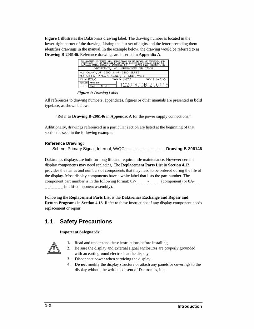
Figure 1 illustrates the Daktronics drawing label. The drawing number is located in the lower-right corner of the drawing. Listing the last set of digits and the letter preceding them identifies drawings in the manual. In the example below, the drawing would be referred to as Drawing B-206146. Reference drawings are inserted in Appendix A.
Figure 1: Drawing Label
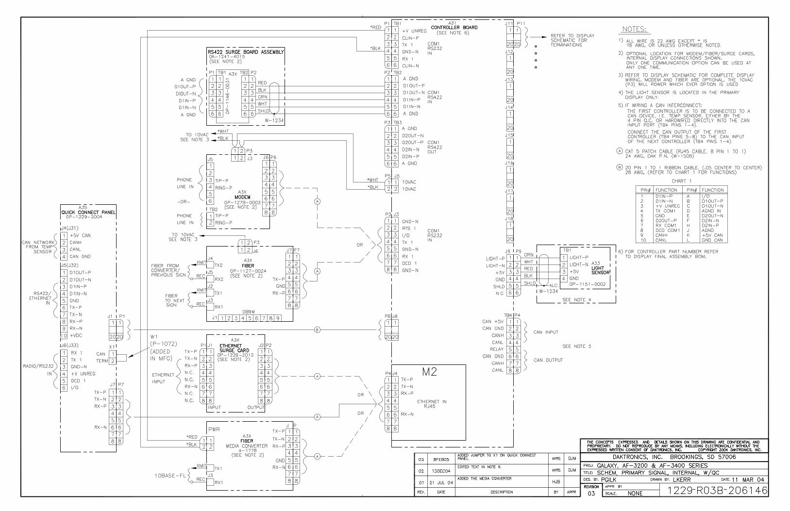
All references to drawing numbers, appendices, figures or other manuals are presented in bold typeface, as shown below.
“Refer to Drawing B-206146 in Appendix A for the power supply connections.” Additionally, drawings referenced in a particular section are listed at the beginning of that section as seen in the following example: Reference Drawing: Schem; Primary Signal, Internal, W/QC ................................... Drawing B-206146 Daktronics displays are built for long life and require little maintenance. However certain display components may need replacing. The Replacement Parts List in Section 4.12 provides the names and numbers of components that may need to be ordered during the life of the display. Most display components have a white label that lists the part number. The component part number is in the following format: 0P-_ _ _ _-_ _ _ _ (component) or 0A-_ _ _ _-_ _ _ _ (multi-component assembly). Following the Replacement Parts List is the Daktronics Exchange and Repair and Return Programs in Section 4.13. Refer to these instructions if any display component needs replacement or repair.
1.1 Safety Precautions Important Safeguards:
1. Read and understand these instructions before installing. 2. Be sure the display and external signal enclosures are properly grounded
with an earth ground electrode at the display. 3. Disconnect power when servicing the display. 4. Do not modify the display structure or attach any panels or coverings to the
display without the written consent of Daktronics, Inc.
Introduction 1-2
Introduction
1-3
Note: This equipment has been tested and found to comply with the limits for a Class A digital device, pursuant to part 15 of the FCC Rules. These limits are designed to provide reasonable protection against harmful interference when the equipment is operated in a commercial environment. This equipment generates, uses, can radiate radio frequency energy, and if not installed and used in accordance with the instruction manual, may cause harmful interference to radio communications. Operation of this equipment in a residential area is likely to cause harmful interference. In such cases, the user will be required to correct the interference at their own expense. Modifications not expressly approved by the manufacturer could void the user's authority to operate the equipment under FCC rules.
1.2 Network Concepts The concept of using LED displays as a cost effective and high impact method of communication is rapidly growing throughout many industries and businesses. The reasons for this growth are many, but the need for additional features and the complexity of multiple display installations has emerged. Daktronics display systems have been designed to meet those needs. The common thread to most client requests is a means of programming and controlling a group of displays from a central control point. Daktronics responded by developing a powerful system of interconnecting and controlling displays. Great care has been taken to design products that will satisfy a wide variety of installations. Some of the design goals of these systems include the following:
• Easy transfer of messages • The ability to tell a display or group of displays in the network which
message should run • The ability to determine the status of any display on the network • The ability to control multiple display technologies on the same network
There are six network systems available: RS232, RS422, modem, fiber, radio and Ethernet. They differ on the type of physical connections needed, the distance allowed and equipment required. A separate manual is provided for the type of communication method ordered with the display. See Section 3.7 for the communication manual ED numbers. Up to 240 displays can exist on one network.
Introduction 1-4
1.3 Display Overview Reference Drawing:
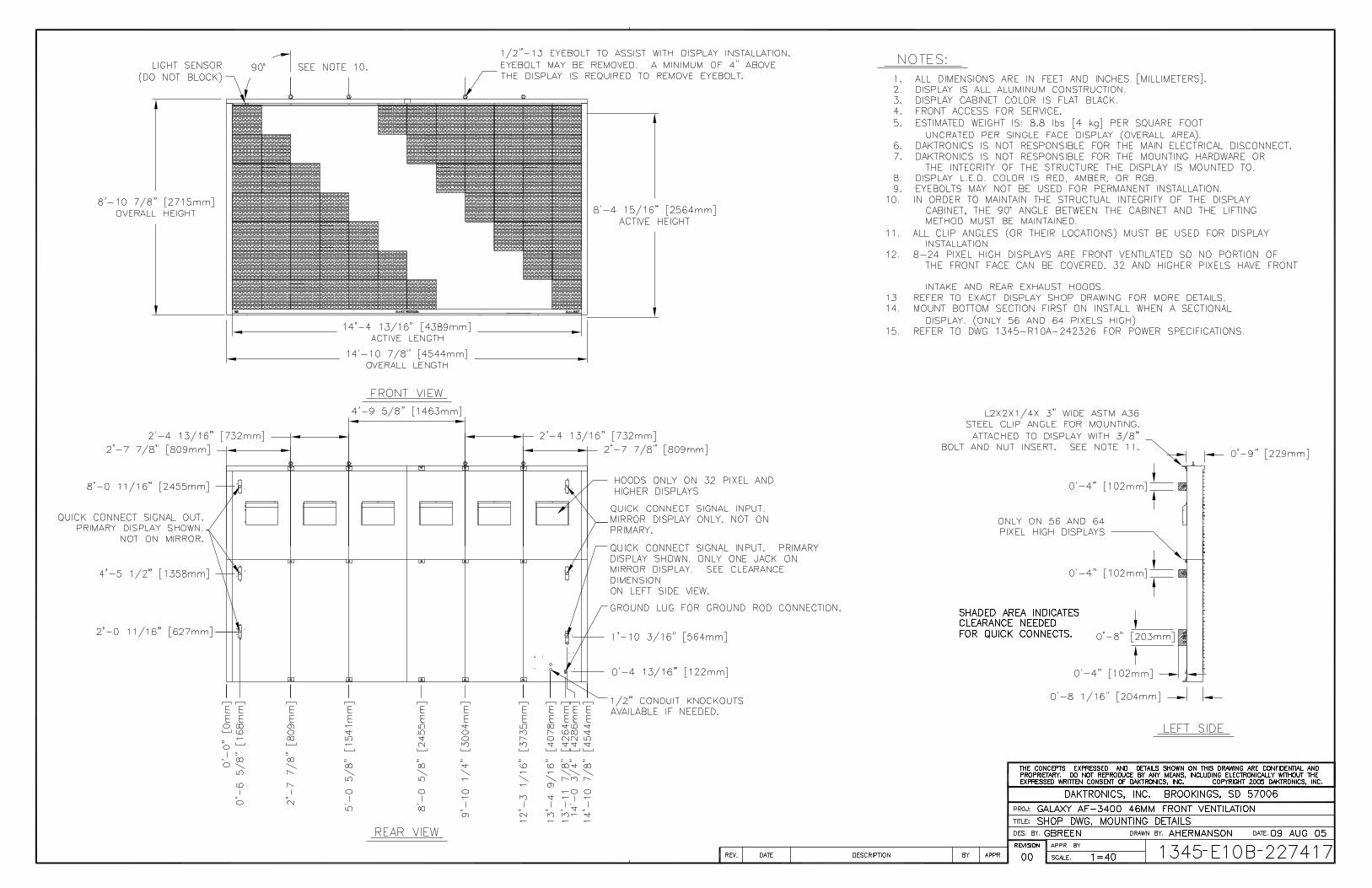
Shop Drawing, Mounting Details ................................. Drawing B-227417 Daktronics 46 mm, AF-3400 Galaxy® displays are designed and manufactured for performance, reliability, easy maintenance and long life. The pixels have a 46 mm center-to-center spacing and are lit using LEDs (light emitting diodes). A light sensor on the front of the primary display is used for automatic dimming of the LEDs based on the ambient light levels. The configuration of pixels depends on the model of display ordered. Refer to Drawing B-227417 for the approximate size and weight for your display model.
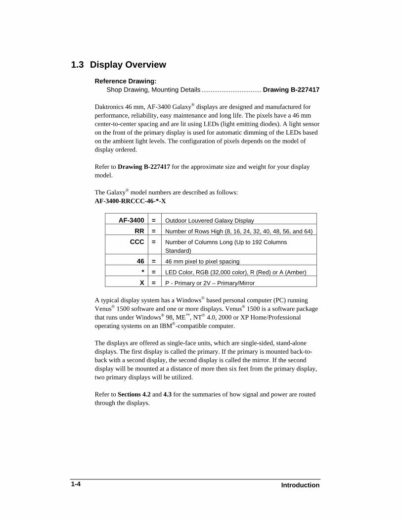
The Galaxy® model numbers are described as follows: AF-3400-RRCCC-46-*-X
AF-3400 = Outdoor Louvered Galaxy Display
RR = Number of Rows High (8, 16, 24, 32, 40, 48, 56, and 64)
CCC = Number of Columns Long (Up to 192 Columns Standard)
46 = 46 mm pixel to pixel spacing
* = LED Color, RGB (32,000 color), R (Red) or A (Amber)
X = P - Primary or 2V – Primary/Mirror
A typical display system has a Windows® based personal computer (PC) running Venus® 1500 software and one or more displays. Venus® 1500 is a software package that runs under Windows® 98, ME™, NT® 4.0, 2000 or XP Home/Professional operating systems on an IBM®-compatible computer. The displays are offered as single-face units, which are single-sided, stand-alone displays. The first display is called the primary. If the primary is mounted back-to-back with a second display, the second display is called the mirror. If the second display will be mounted at a distance of more then six feet from the primary display, two primary displays will be utilized. Refer to Sections 4.2 and 4.3 for the summaries of how signal and power are routed through the displays.
1.4 Component Identification The following illustrations depict some of the more commonly accessed Galaxy® display components. Because Daktronics occasionally alters standard design to meet customer needs, the actual display design may vary slightly from the illustrations below. This is only a brief overview. Refer to Section 4 for additional information on maintaining the various display components. Additional definitions are given in the communication manual provided with your display.
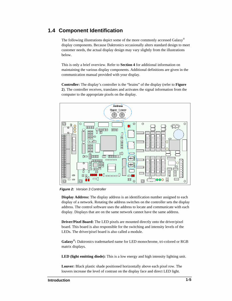
Controller: The display’s controller is the “brains” of the display (refer to Figure 2). The controller receives, translates and activates the signal information from the computer to the appropriate pixels on the display.
Figure 2: Version 3 Controller
Display Address: The display address is an identification number assigned to each display of a network. Rotating the address switches on the controller sets the display address. The control software uses the address to locate and communicate with each display. Displays that are on the same network cannot have the same address. Driver/Pixel Board: The LED pixels are mounted directly onto the driver/pixel board. This board is also responsible for the switching and intensity levels of the LEDs. The driver/pixel board is also called a module. Galaxy®: Daktronics trademarked name for LED monochrome, tri-colored or RGB matrix displays. LED (light emitting diode): This is a low energy and high intensity lighting unit. Louver: Black plastic shade positioned horizontally above each pixel row. The louvers increase the level of contrast on the display face and direct LED light.
Introduction
1-5
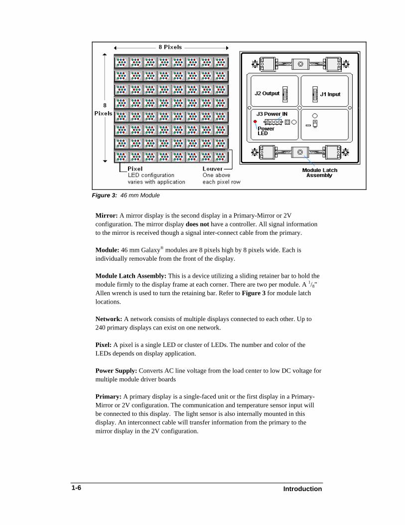
Figure 3: 46 mm Module
Mirror: A mirror display is the second display in a Primary-Mirror or 2V configuration. The mirror display does not have a controller. All signal information to the mirror is received though a signal inter-connect cable from the primary. Module: 46 mm Galaxy® modules are 8 pixels high by 8 pixels wide. Each is individually removable from the front of the display. Module Latch Assembly: This is a device utilizing a sliding retainer bar to hold the module firmly to the display frame at each corner. There are two per module. A 1/8" Allen wrench is used to turn the retaining bar. Refer to Figure 3 for module latch locations. Network: A network consists of multiple displays connected to each other. Up to 240 primary displays can exist on one network. Pixel: A pixel is a single LED or cluster of LEDs. The number and color of the LEDs depends on display application. Power Supply: Converts AC line voltage from the load center to low DC voltage for multiple module driver boards Primary: A primary display is a single-faced unit or the first display in a Primary-Mirror or 2V configuration. The communication and temperature sensor input will be connected to this display. The light sensor is also internally mounted in this display. An interconnect cable will transfer information from the primary to the mirror display in the 2V configuration.
Introduction 1-6
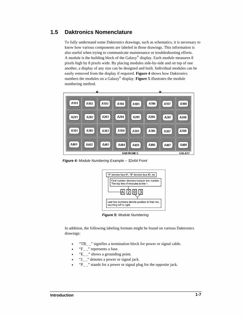
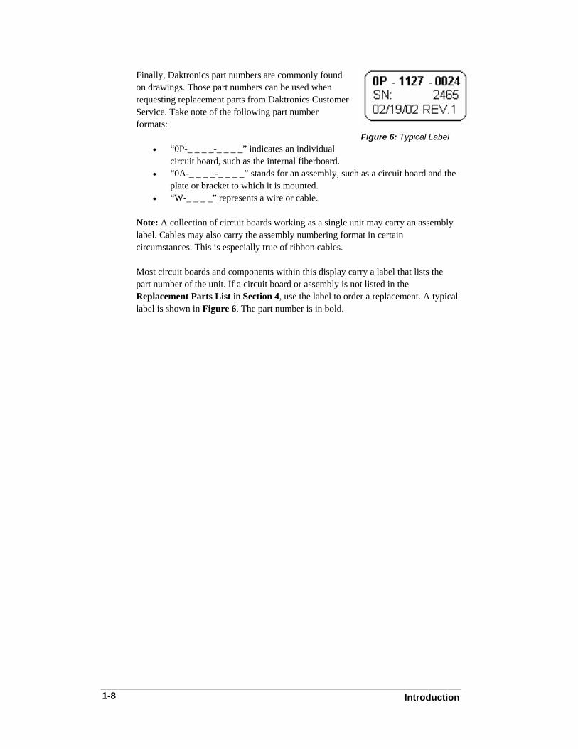
1.5 Daktronics Nomenclature To fully understand some Daktronics drawings, such as schematics, it is necessary to know how various components are labeled in those drawings. This information is also useful when trying to communicate maintenance or troubleshooting efforts. A module is the building block of the Galaxy® display. Each module measures 8 pixels high by 8 pixels wide. By placing modules side-by-side and on top of one another, a display of any size can be designed and built. Individual modules can be easily removed from the display if required. Figure 4 shows how Daktronics numbers the modules on a Galaxy® display. Figure 5 illustrates the module numbering method.
Figure 4: Module Numbering Example – 32x64 Front
Figure 5: Module Numbering
In addition, the following labeling formats might be found on various Daktronics drawings:
• “TB_ _” signifies a termination block for power or signal cable. • “F_ _” represents a fuse. • “E_ _” shows a grounding point. • “J_ _” denotes a power or signal jack. • “P_ _” stands for a power or signal plug for the opposite jack.
Introduction
1-7
Figure 6: Typical Label
Finally, Daktronics part numbers are commonly found on drawings. Those part numbers can be used when requesting replacement parts from Daktronics Customer Service. Take note of the following part number formats:
• “0P-_ _ _ _-_ _ _ _” indicates an individual circuit board, such as the internal fiberboard.
• “0A-_ _ _ _-_ _ _ _” stands for an assembly, such as a circuit board and the plate or bracket to which it is mounted.
• “W-_ _ _ _” represents a wire or cable. Note: A collection of circuit boards working as a single unit may carry an assembly label. Cables may also carry the assembly numbering format in certain circumstances. This is especially true of ribbon cables. Most circuit boards and components within this display carry a label that lists the part number of the unit. If a circuit board or assembly is not listed in the Replacement Parts List in Section 4, use the label to order a replacement. A typical label is shown in Figure 6. The part number is in bold.
Introduction 1-8
Mechanical Installation
2-1
Section 2: Mechanical Installation
Note: Daktronics does not guarantee the warranty in situations where the display is not constantly in a stable environment. The Daktronics engineering staff must approve any changes that may affect the weather-tightness of the display. If any modifications are made, detailed drawings of the changes must be submitted to Daktronics for evaluation and approval or the warranty may be void. Daktronics is not responsible for installations or the structural integrity of support structures done by others. It is the customer’s responsibility to ensure that a qualified structural engineer approves the structure and any additional hardware.
2.1 Mechanical Installation Overview Because every installation site is unique, there is no single Daktronics-approved procedure for mounting the Galaxy® displays. The information contained in this section is general information only and may or may not be appropriate for your particular installation. A qualified individual must make all decisions regarding the mounting of this display. Read both the mechanical and electrical installation sections of this manual before beginning any installation procedures.
2.2 Support Structure Design Support structure design depends on the mounting methods, display size and weight. The structure design is critical and should be done only by a qualified individual. Display height and wind loading are also critical factors. It is the customer’s responsibility to ensure that the structure and mounting hardware are adequate. Daktronics is not responsible for the installations or the structural integrity of support structures done by others. It is the installer’s responsibility to ensure the mounting structure and hardware are capable of supporting the display and will agree with local codes. Before beginning the installation process, verify the following:
• All clip angles or mounting holes must be attached to the support structure. • The mounting structure will provide a straight and square-mounting frame
for the display. • The mounting structure is capable of supporting the display and will not
yield at any unsupported points after mounting. • Clearance: 4" of unobstructed space is available above the top of the display
to remove the eyebolt. Note: No clearance is required once the eyebolt is removed. Correct any deficiencies before installation.
2.3 Ventilation Requirements Reference Drawing:
Shop Drawing, Mounting Details ................................. Drawing B-227417 Vents are provided in the face of the display for ventilation. Vents and fans draw air into the front of the display at the bottom, and the warm air is expelled out the top of the display through vents in the front. Both the intake and exhaust vents run the length of the display and should not be obstructed. Refer to Shop Drawing B-227417 for additional information. The display cabinet may be completely enclosed on the sides and in back, only if the vents in the face are not obstructed. In some displays there will be a hood on the backsheet, and the back of the display cannot be covered. If these requirements are not met, the Galaxy® display warranty may be void.
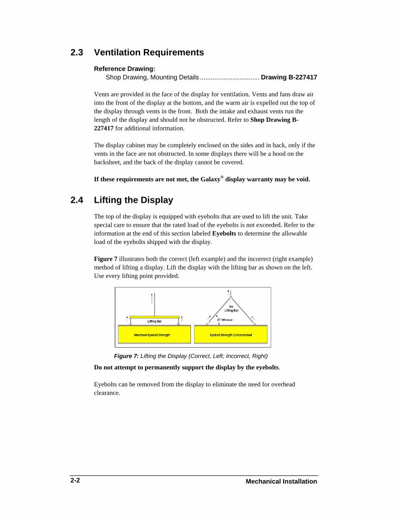
2.4 Lifting the Display The top of the display is equipped with eyebolts that are used to lift the unit. Take special care to ensure that the rated load of the eyebolts is not exceeded. Refer to the information at the end of this section labeled Eyebolts to determine the allowable load of the eyebolts shipped with the display. Figure 7 illustrates both the correct (left example) and the incorrect (right example) method of lifting a display. Lift the display with the lifting bar as shown on the left. Use every lifting point provided.
Figure 7: Lifting the Display (Correct, Left; Incorrect, Right)
Do not attempt to permanently support the display by the eyebolts. Eyebolts can be removed from the display to eliminate the need for overhead clearance.
Mechanical Installation 2-2
Mechanical Installation
2-3
2.5 Display Mounting Reference Drawing:
Shop Drawing, Mounting Details..................................Drawing B-227417 The method used to mount displays can vary greatly from location to location. For this reason, only general mounting topics can be addressed in this manual. It is the responsibility of the installer to ensure the installation will adequately meet local codes and standards, including the mounting hardware and method. Before beginning the installation process, verify the following items:
• The mounting structure will provide a straight and square-mounting frame for the display – height variation in any four-foot horizontal section may not exceed 1/4-inch.
• The mounting structure will not give way at any unsupported points after the display is mounted.
The back of the display is equipped with 2 x 2 x 3 x 1/4" steel clip angles at the locations shown in Drawing B-227417 for your display size. These angles may be used for mounting purposes. Remember to have all mounted displays inspected by a qualified structural engineer. Refer to the appropriate Drawing B-227417 for a suggested wall mount method. The number of attachment points needed and the wall structure must be reviewed by a qualified structural engineer and meet all national and local codes. It is the customer’s responsibility to determine the proper wall mounting method and location. Daktronics requires using all clip angles or mounting holes as attachment points.
Mounting a Non-Sectional Display 1. Carefully uncrate the display and inspect each side of the display for
possible damage that may have occurred during shipping. 2. If mounting a sectional display, refer to the segment following this
sequence. 3. Following the guidelines described in Section 2.4, lift the display into
position on the support structure. 4. Weld or use 1/2" Grade-5 bolts and hardware to secure the clip angles to the
support structure as shown in the Drawing B-227417 for your display. 5. Refer to Section 3 for information on routing power to the display and the
communication manual for routing the signal. 6. After installation is complete, carefully inspect the display for any holes
that may allow water to seep into the display and seal any openings with silicone – if the eyebolts on the top of the display have been removed, plug the holes with bolts and the flat washer that was removed with the eyebolt (unless there is an overhead structure).
Mechanical Installation 2-4
Mounting a Sectional Display Follow these steps to mount a sectional display. Note: The bottom section has protective faceplates on the top. These faceplates are a protective measure for safe traveling. By removing the faceplates, any and all openings on the top of the bottom section are exposed and the display is vulnerable. Because of this, the top section needs to be attached to the bottom section very soon after the faceplates are removed. Before combining the sections, examine the inside of the bottom display to ensure no foreign objects entered the display that may damage internal components. Daktronics is not responsible for any damage that is a result of postponed top section installation. Behind the second module in the bottom row of the top section is a padded envelope that contains the needed hardware. 1. Carefully uncrate the display and inspect each side of the display for possible
damage that may have occurred during shipping. 2. Mount the bottom section first. 3. Remove the eyebolts from the top of the bottom display that secure the
faceplates. 4. Carefully remove the faceplates making sure not to damage the protective
sealant around the top of the display. Any damage done to the sealant may result in rusting or worse damage to the display. Daktronics is not responsible for any damage resulting in damaged sealant, and if the sealant is harmed during faceplate removal, the warranty will be void.
5. Install alignment pins to help set the top section onto the bottom section. The alignment pins are stored in the padded envelope mentioned above.
6. Following the guidelines described in Section 2.4, lift the bottom display into position on the support structure.
7. Weld or use 1/2" Grade-5 bolts and hardware to secure the clip angles to the support structure as shown in Drawing B-227417.
8. Remove the first, second and every even module from the bottom row on the top section. There should be two holes visible in both the top and bottom sections where the modules are removed.
9. Set the top section on to the mounted bottom section. 10. Remove the alignment pins. 11. Use the bolts found in the padded envelope to secure the top section. 12. Install the bolt and washer into the captivated nut in the bottom section. 13. Torque the bolts to 40-50 ft/lbs torque. 14. Re-install the modules and the power and signal jacks. 15. Refer to Section 3 for information on routing power to the display and the
communication manual for routing the signal. 16. After installation is complete, carefully inspect the display for any holes that
may allow water to seep into the display and seal any openings with silicone – if the eyebolts on the top of the display have been removed, plug the holes with bolts that were removed with the eyebolt (unless there is an overhead structure).
Mechanical Installation
2-5
2.6 Optional Temperature Sensor Mounting If an optional temperature sensor will be used with this display, see Appendix B for mounting and signal connections.
Electrical Installation
3-1
ion Section 3: Electrical Installat
Only a qualified individual should terminate power and signal cable at this Daktronics display. The Daktronics engineering staff must approve any changes made to the display. Before altering the display, submit detailed drawings for the proposed modifications to the Daktronics engineering staff for evaluation and approval, or the warranty will be rendered null and void.
3.1 Common Connectors in the Display The power and signal connections in the displays use many different types of connectors. Take special care when disengaging any connector so as not to damage the connector, the cable or the circuit board. When pulling a connector plug from a jack, do not pull on the wire or cable; pull on the jack itself. Pulling on the wires may damage the connector. The following information presents some common connectors encountered during display installation and maintenance:
Ribbon Cable Connectors:
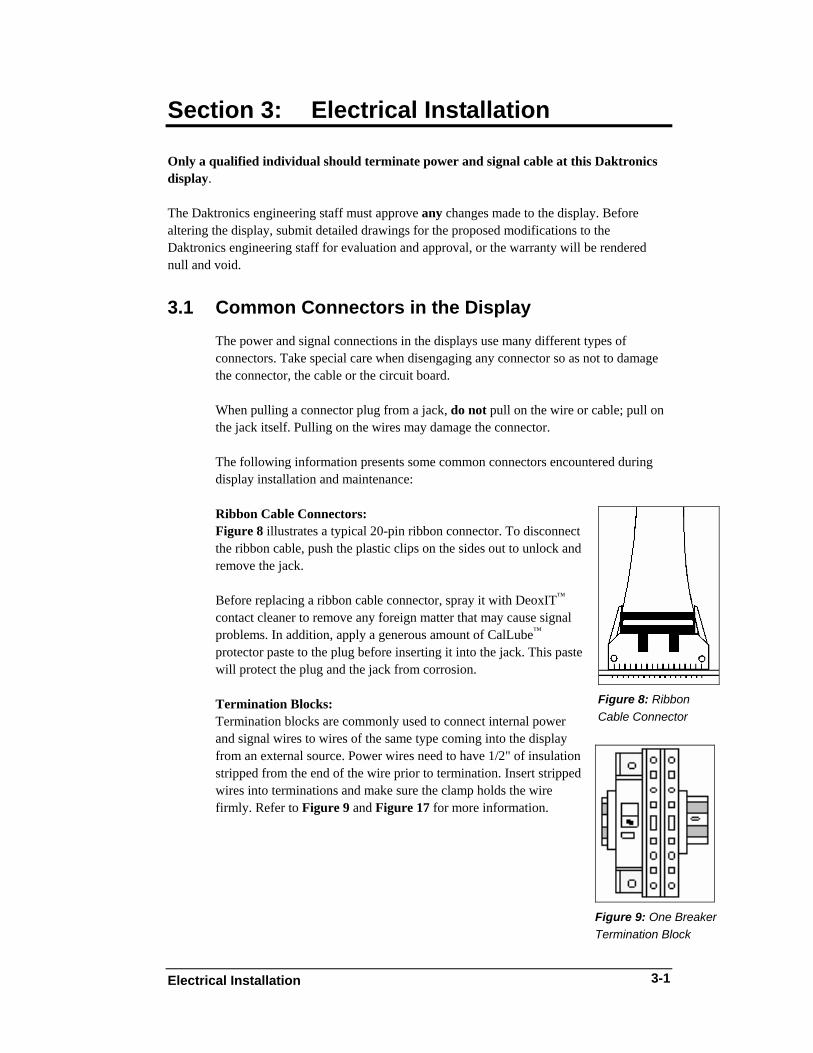
Figure 8: Ribbon Cable Connector
Figure 8 illustrates a typical 20-pin ribbon connector. To disconnect the ribbon cable, push the plastic clips on the sides out to unlock and remove the jack. Before replacing a ribbon cable connector, spray it with DeoxIT™ contact cleaner to remove any foreign matter that may cause signal problems. In addition, apply a generous amount of CalLube™ protector paste to the plug before inserting it into the jack. This paste will protect the plug and the jack from corrosion.
Termination Blocks: Termination blocks are commonly used to connect internal power and signal wires to wires of the same type coming into the display from an external source. Power wires need to have 1/2" of insulation stripped from the end of the wire prior to termination. Insert stripped wires into terminations and make sure the clamp holds the wire firmly. Refer to Figure 9 and Figure 17 for more information.
Figure 9: One Breaker Termination Block
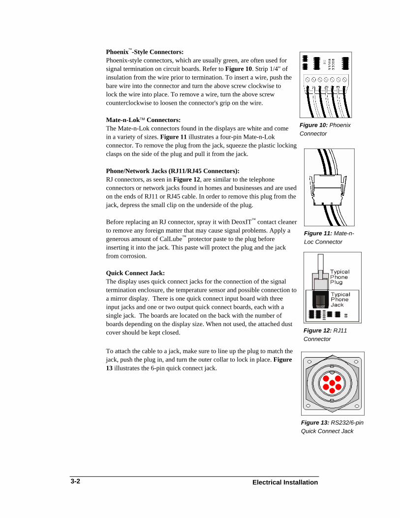
Phoenix™-Style Connectors:
Figure 10: Phoenix Connector
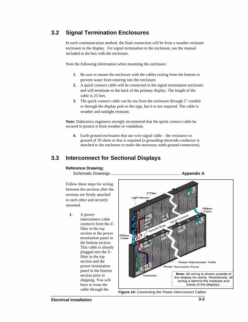
Phoenix-style connectors, which are usually green, are often used for signal termination on circuit boards. Refer to Figure 10. Strip 1/4" of insulation from the wire prior to termination. To insert a wire, push the bare wire into the connector and turn the above screw clockwise to lock the wire into place. To remove a wire, turn the above screw counterclockwise to loosen the connector's grip on the wire. Mate-n-Lok™ Connectors: The Mate-n-Lok connectors found in the displays are white and come in a variety of sizes. Figure 11 illustrates a four-pin Mate-n-Lok connector. To remove the plug from the jack, squeeze the plastic locking clasps on the side of the plug and pull it from the jack.
Figure 11: Mate-n-Loc Connector
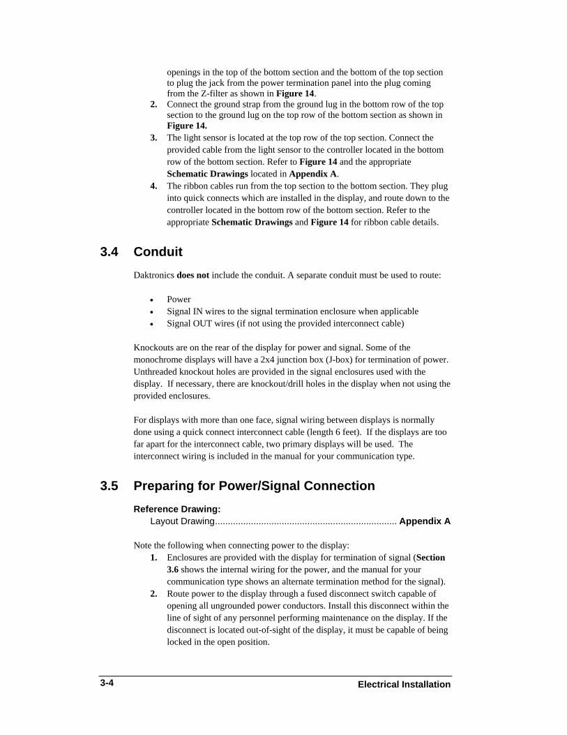
Phone/Network Jacks (RJ11/RJ45 Connectors): RJ connectors, as seen in Figure 12, are similar to the telephone connectors or network jacks found in homes and businesses and are used on the ends of RJ11 or RJ45 cable. In order to remove this plug from the jack, depress the small clip on the underside of the plug. Before replacing an RJ connector, spray it with DeoxIT™ contact cleaner to remove any foreign matter that may cause signal problems. Apply a generous amount of CalLube™ protector paste to the plug before inserting it into the jack. This paste will protect the plug and the jack from corrosion.
Figure 12: RJ11 Connector
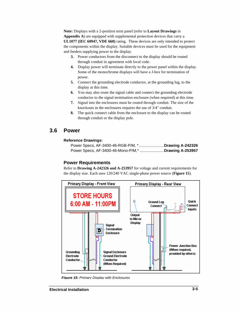
Quick Connect Jack: The display uses quick connect jacks for the connection of the signal termination enclosure, the temperature sensor and possible connection to a mirror display. There is one quick connect input board with three input jacks and one or two output quick connect boards, each with a single jack. The boards are located on the back with the number of boards depending on the display size. When not used, the attached dust cover should be kept closed. To attach the cable to a jack, make sure to line up the plug to match the jack, push the plug in, and turn the outer collar to lock in place. Figure 13 illustrates the 6-pin quick connect jack.
Figure 13: RS232/6-pin Quick Connect Jack
Electrical Installation 3-2
3.2 Signal Termination Enclosures In each communication method, the final connection will be from a weather resistant enclosure to the display. For signal termination to the enclosure, see the manual included in the box with the enclosure. Note the following information when mounting the enclosure:
1. Be sure to mount the enclosure with the cables exiting from the bottom to
prevent water from entering into the enclosure. 2. A quick connect cable will be connected to the signal termination enclosure
and will terminate to the back of the primary display. The length of the cable is 25 feet.
3. The quick connect cable can be run from the enclosure through 2" conduit or through the display pole to the sign, but it is not required. The cable is weather and sunlight resistant.
Note: Daktronics engineers strongly recommend that the quick connect cable be secured to protect it from weather or vandalism.
4. Earth ground enclosures that use wire signal cable – the resistance to ground of 10 ohms or less is required (a grounding electrode conductor is attached to the enclosure to make the necessary earth ground connection).
3.3 Interconnect for Sectional Displays Reference Drawing:
Schematic Drawings ...............................................................Appendix A
Figure 14: Connecting the Power Interconnect Cables
Follow these steps for wiring between the sections after the sections are firmly attached to each other and securely mounted.
1. A power
interconnect cable connects from the Z-filter in the top section to the power termination panel in the bottom section. This cable is already plugged into the Z-filter in the top section and the power termination panel in the bottom section prior to shipping. You will have to route the cable through the
Electrical Installation
3-3
Electrical Installation 3-4
openings in the top of the bottom section and the bottom of the top section to plug the jack from the power termination panel into the plug coming from the Z-filter as shown in Figure 14.
2. Connect the ground strap from the ground lug in the bottom row of the top section to the ground lug on the top row of the bottom section as shown in Figure 14.
3. The light sensor is located at the top row of the top section. Connect the provided cable from the light sensor to the controller located in the bottom row of the bottom section. Refer to Figure 14 and the appropriate Schematic Drawings located in Appendix A.
4. The ribbon cables run from the top section to the bottom section. They plug into quick connects which are installed in the display, and route down to the controller located in the bottom row of the bottom section. Refer to the appropriate Schematic Drawings and Figure 14 for ribbon cable details.
3.4 Conduit Daktronics does not include the conduit. A separate conduit must be used to route:
• Power • Signal IN wires to the signal termination enclosure when applicable • Signal OUT wires (if not using the provided interconnect cable)
Knockouts are on the rear of the display for power and signal. Some of the monochrome displays will have a 2x4 junction box (J-box) for termination of power. Unthreaded knockout holes are provided in the signal enclosures used with the display. If necessary, there are knockout/drill holes in the display when not using the provided enclosures. For displays with more than one face, signal wiring between displays is normally done using a quick connect interconnect cable (length 6 feet). If the displays are too far apart for the interconnect cable, two primary displays will be used. The interconnect wiring is included in the manual for your communication type.
3.5 Preparing for Power/Signal Connection Reference Drawing:
Layout Drawing....................................................................... Appendix A Note the following when connecting power to the display:
1. Enclosures are provided with the display for termination of signal (Section 3.6 shows the internal wiring for the power, and the manual for your communication type shows an alternate termination method for the signal).
2. Route power to the display through a fused disconnect switch capable of opening all ungrounded power conductors. Install this disconnect within the line of sight of any personnel performing maintenance on the display. If the disconnect is located out-of-sight of the display, it must be capable of being locked in the open position.
Note: Displays with a 2-position term panel (refer to Layout Drawings in Appendix A) are equipped with supplemental protection devices that carry a UL1077 (IEC 60947, VDE 660) rating. These devices are only intended to protect the components within the display. Suitable devices must be used for the equipment and feeders supplying power to the display.
3. Power conductors from the disconnect to the display should be routed through conduit in agreement with local code.
4. Display power will terminate directly to the power panel within the display. Some of the monochrome displays will have a J-box for termination of power.
5. Connect the grounding electrode conductor, at the grounding lug, to the display at this time.
6. You may also route the signal cable and connect the grounding electrode conductor to the signal termination enclosure (when required) at this time.
7. Signal into the enclosures must be routed through conduit. The size of the knockouts in the enclosures requires the use of 3/4" conduit.
8. The quick connect cable from the enclosure to the display can be routed through conduit or the display pole.
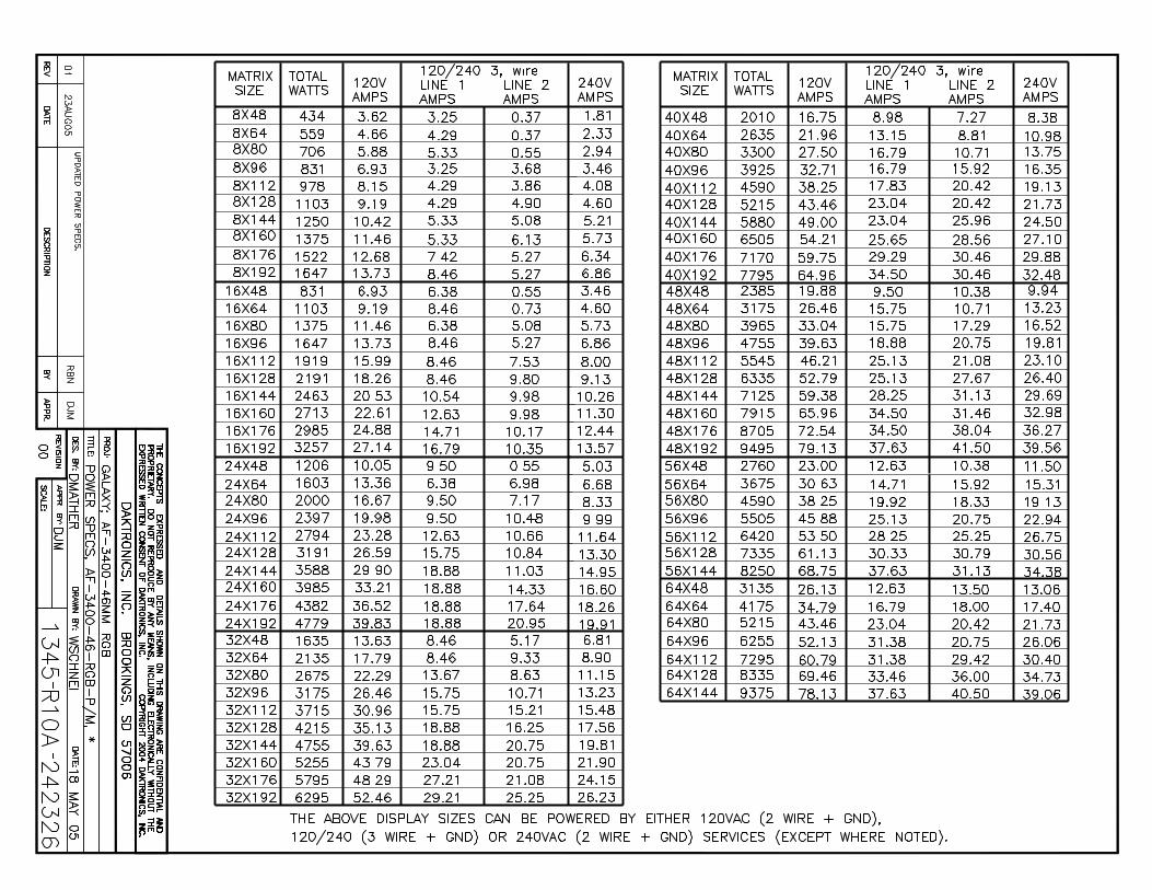
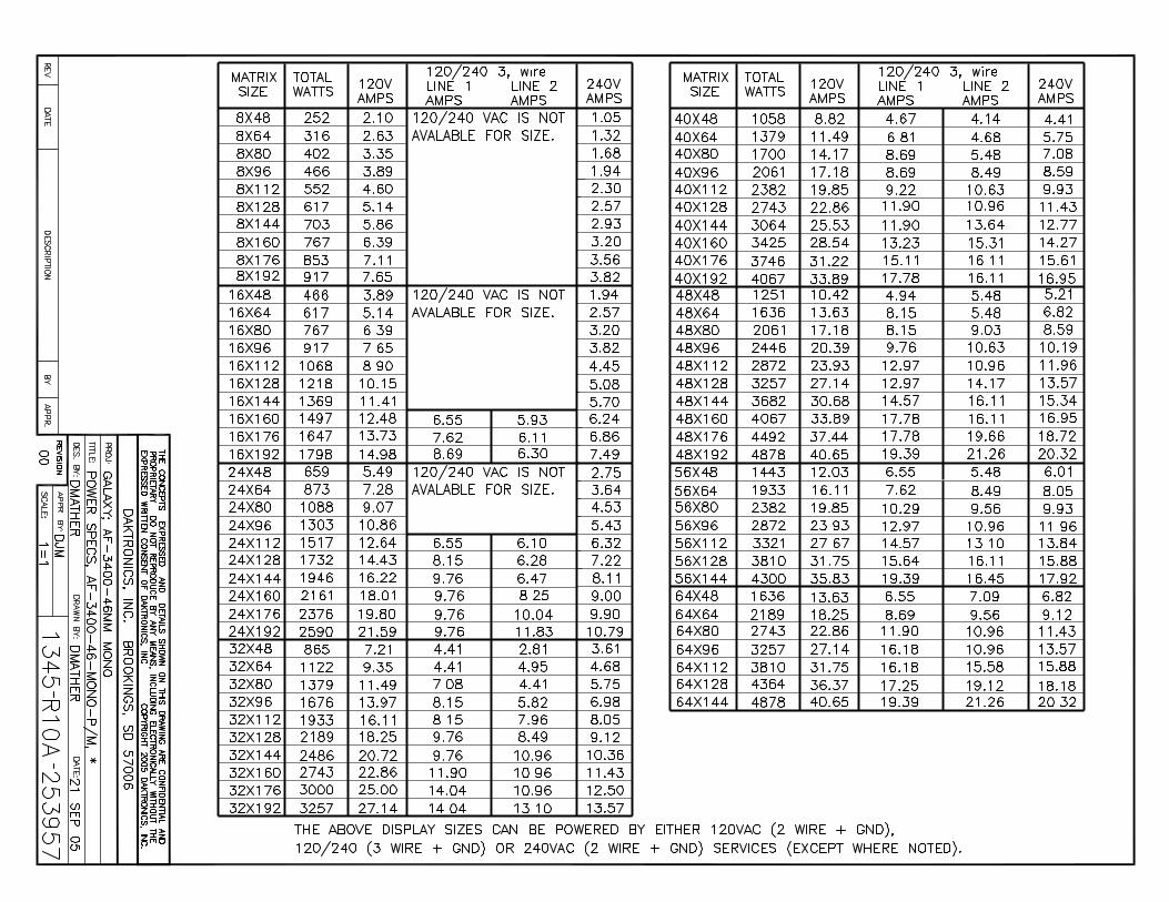
3.6 Power Reference Drawings: Power Specs, AF-3400-46-RGB-P/M, *.......................Drawing A-242326 Power Specs, AF-3400-46-Mono-P/M,* ......................Drawing A-253957
Power Requirements Refer to Drawing A-242326 and A-253957 for voltage and current requirements for the display size. Each uses 120/240 VAC single-phase power source (Figure 15).
Figure 15: Primary Display with Enclosures
Electrical Installation
3-5
Electrical Installation 3-6
Do not connect the displays to any voltage other than that listed on the Daktronics product label. Proper power installation is imperative for proper display operation. The following sub-sections give details of display power installation.
Grounding This sign is intended to be installed in accordance with the requirements of Article 600 of the National Electrical Code and/or other applicable local codes. This includes proper grounding and bonding of the sign. Displays must be grounded according to the provisions outlined in Article 250 of the National Electrical Code®. Daktronics requires a resistance to ground of 10 ohms or less. The display system must be connected to earth-ground. Proper grounding is necessary for reliable equipment operation. It also protects the equipment from damaging electrical disturbances and lightning. The display must be properly grounded or the warranty will be void. The material of an earth-ground electrode differs from region to region and from conditions present at the site. Consult the National Electrical Code and any local electrical codes that may apply. The support structure of the display cannot be used as an earth-ground electrode. The support is generally embedded in concrete, and if in earth, the steel is either primed, or it corrodes making it a poor ground. A minimum of one grounding electrode must be installed for each display face. The grounding electrode is typically one grounding rod for each display face. Other grounding electrodes as described in Article 250 of the National Electric Code may be used. Daktronics requires that the resistance to ground be 10 ohms or less. If the resistance to ground is higher than 10 ohms, it will be necessary to install additional grounding electrodes to reduce the resistance. The grounding electrode should be installed within 25 feet of the base of the display. The grounding electrode must be connected to the ground terminal lug on the back of the display.
Power Installation For these displays, installation with provided ground and neutral conductors is used.
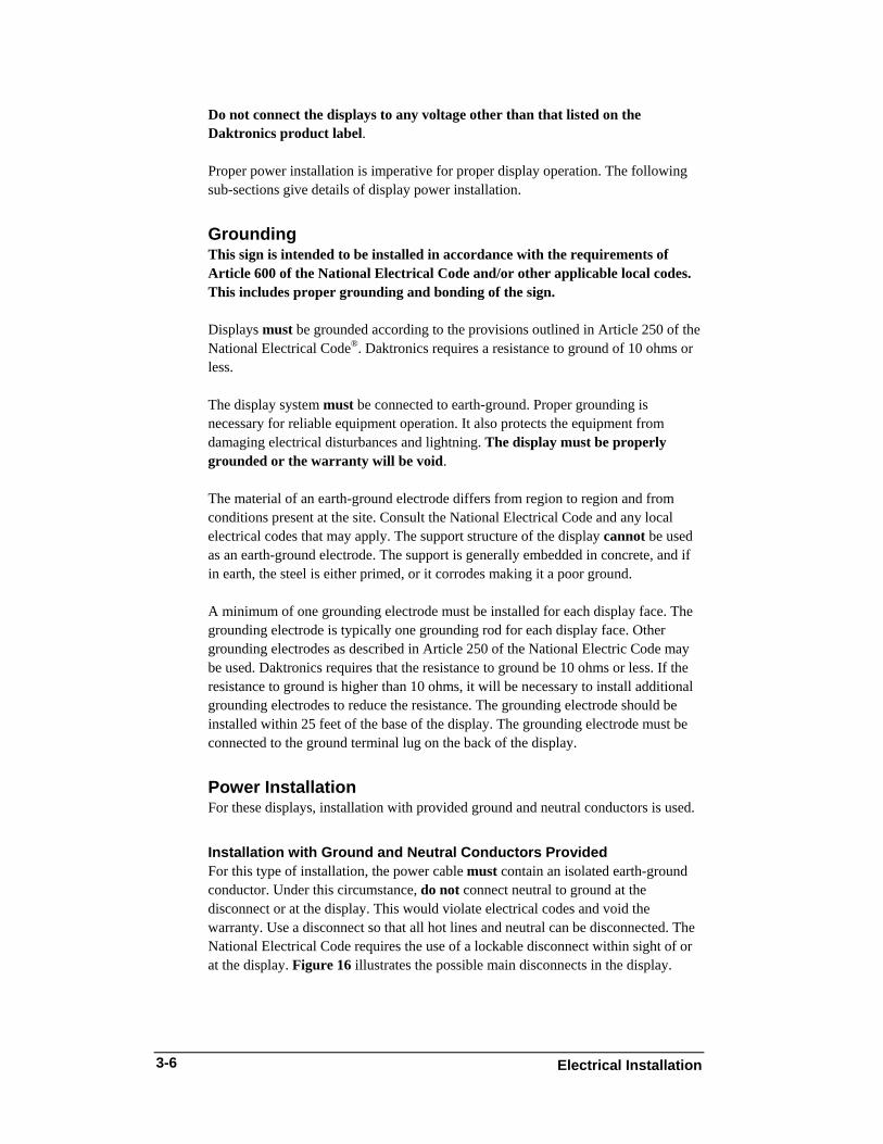
Installation with Ground and Neutral Conductors Provided For this type of installation, the power cable must contain an isolated earth-ground conductor. Under this circumstance, do not connect neutral to ground at the disconnect or at the display. This would violate electrical codes and void the warranty. Use a disconnect so that all hot lines and neutral can be disconnected. The National Electrical Code requires the use of a lockable disconnect within sight of or at the display. Figure 16 illustrates the possible main disconnects in the display.
Figure 16: Installation with Ground and Neutral Conductors
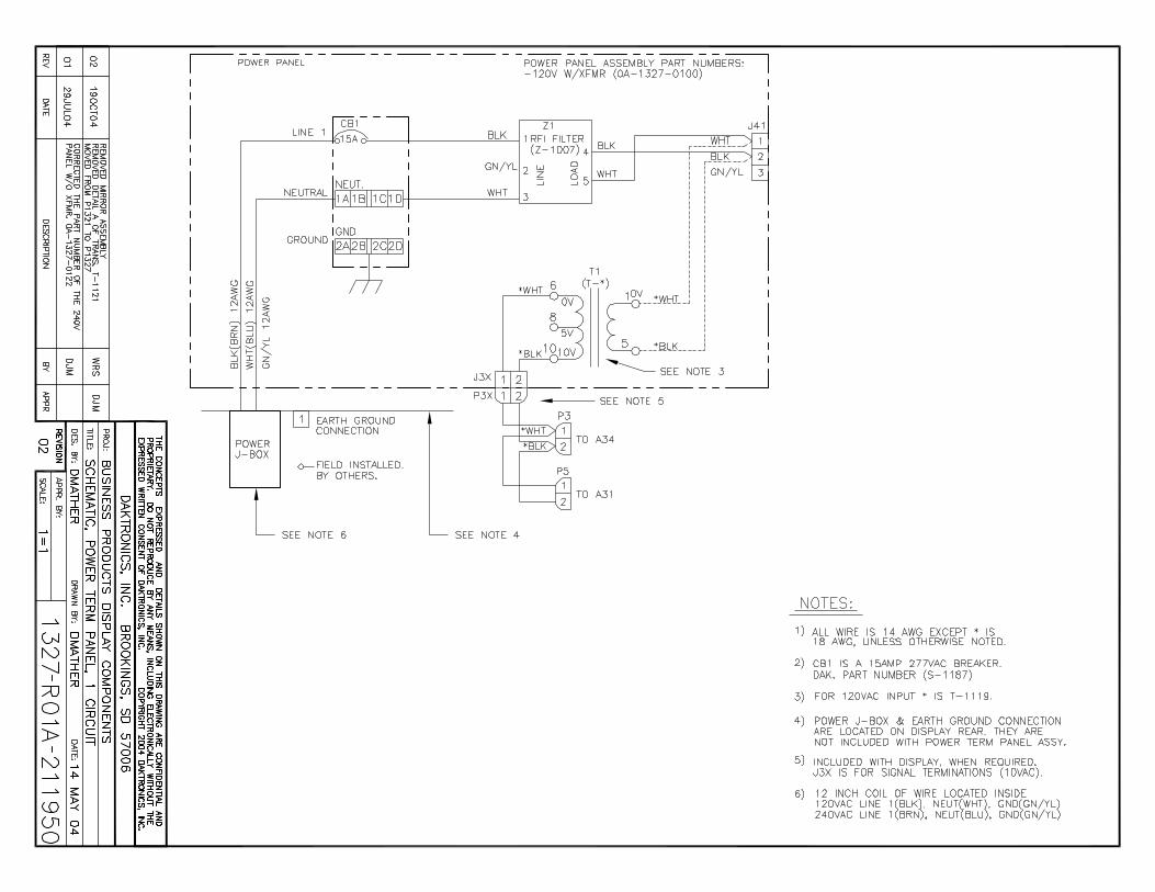
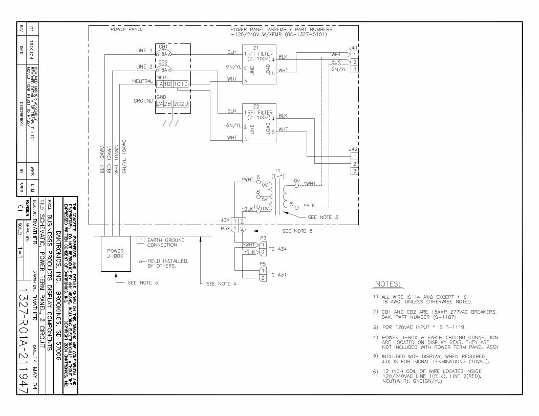
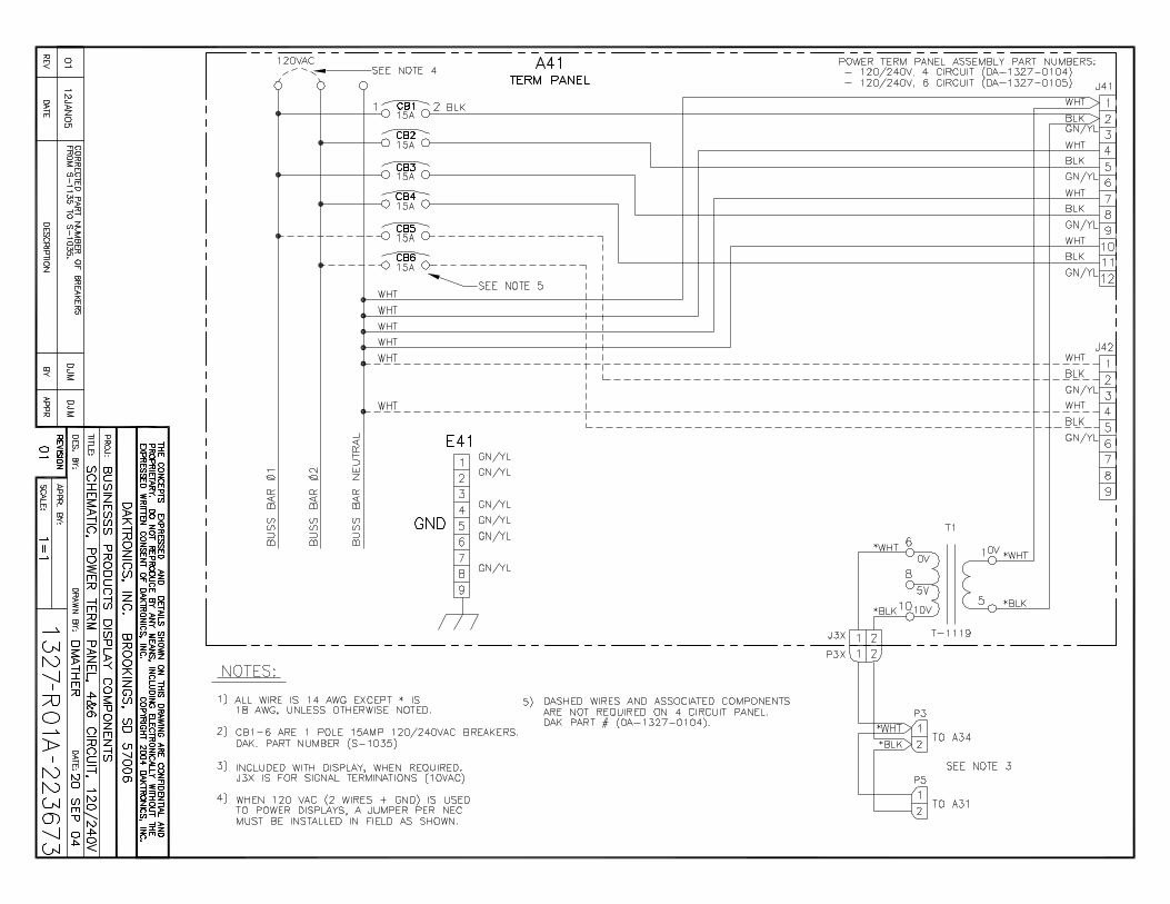
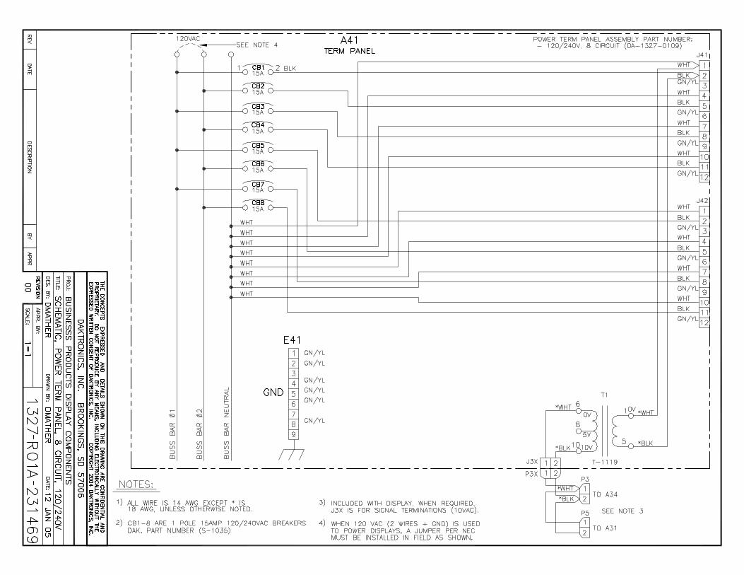
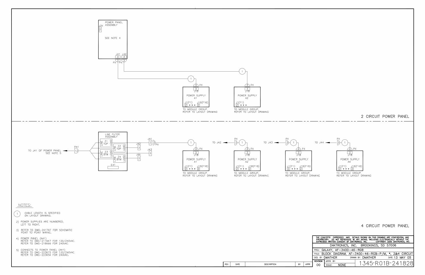
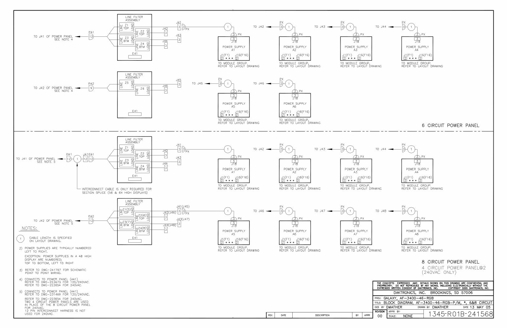
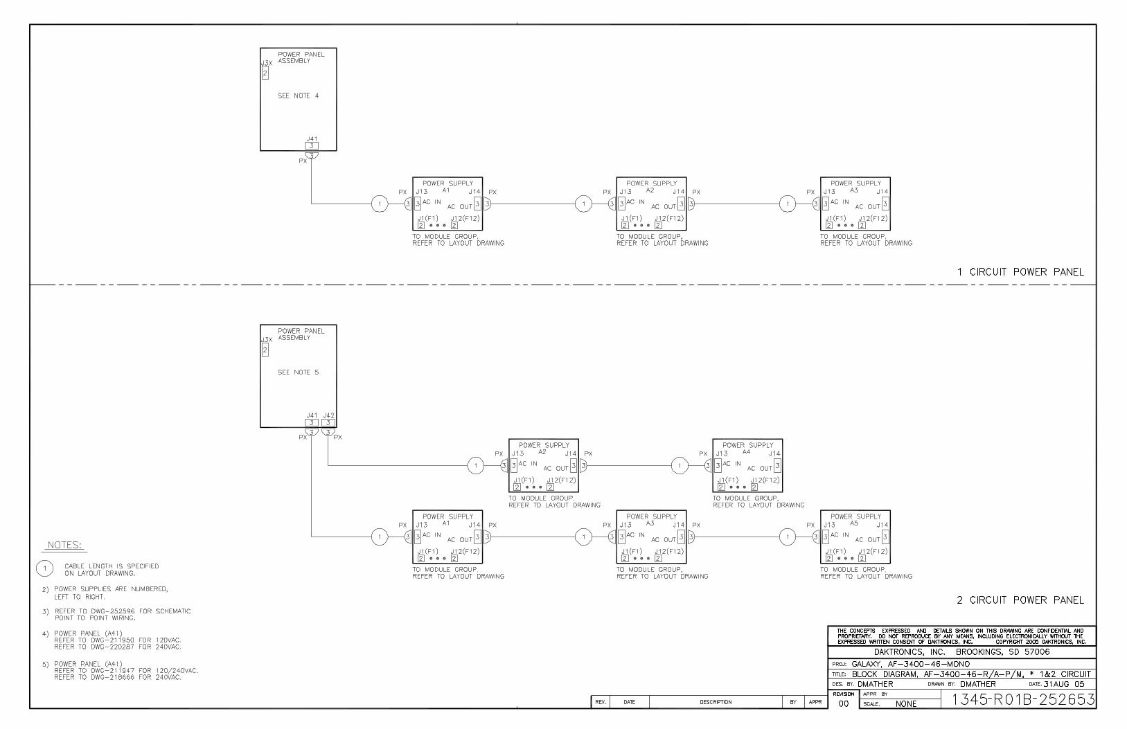
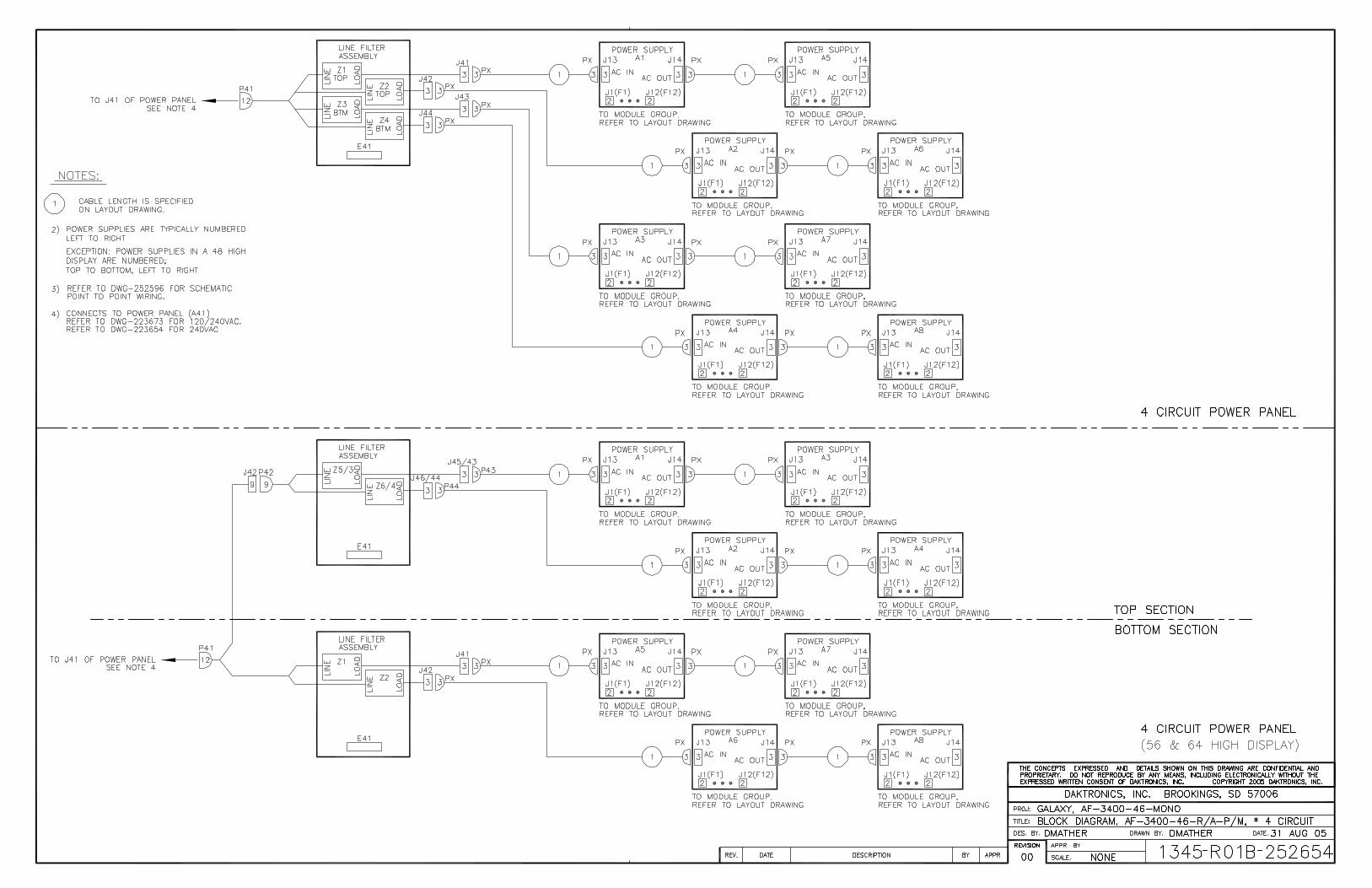
Power Connection Reference Drawings: Schematic, Power Term Panel, 1 circuit ............................Drawing A-211950 Schematic, Power Term Panel, 2 circuit ............................Drawing A-211947 Schematic, Power Term Panel, 4&6 circuit ........................Drawing A-223673 Schematic, Power Term Panel, 8 circuit ............................Drawing A-231469 Display power is connected to the power termination panel in the display. Complete the following steps to terminate the hot, neutral and ground wires at the termination panel. The display is equipped with 3/4" knockouts. If these are not sufficient, size the hole to match the conduit size required.
Route the power cable through conduit to the rear of the display and into the power termination panel.
Note: the following colors are used for the pre-terminated wires (2 position panel only):
• Line 1 – Black (Brown – 240V) • Line 2 – Red (only on three wire installations – 120/240V) • Neutral - White (Blue – 240V) • Grounding Conductor - (Green-Yellow)
Electrical Installation
3-7
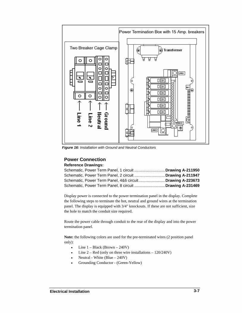
Figure 17: Making Cage Clamp Connections
The following steps will need to be done to complete internal connections:
1. Open the display as explained in Section 4.4 and locate the power termination panel for these displays.
2. Route the cable through conduit to the back of the display. Use the 3/4" knockout for access, being careful not to damage any internal components.
3. Disconnect the wires to the terminal block and connect the wires from the direct cable.
4. Using a small flat screwdriver to open the cage clamps, release the jumper wires connected to the external wires going to the external power termination box.
5. Install the wires from the direct circuit into the cage clamps following the directions in Figure 17.
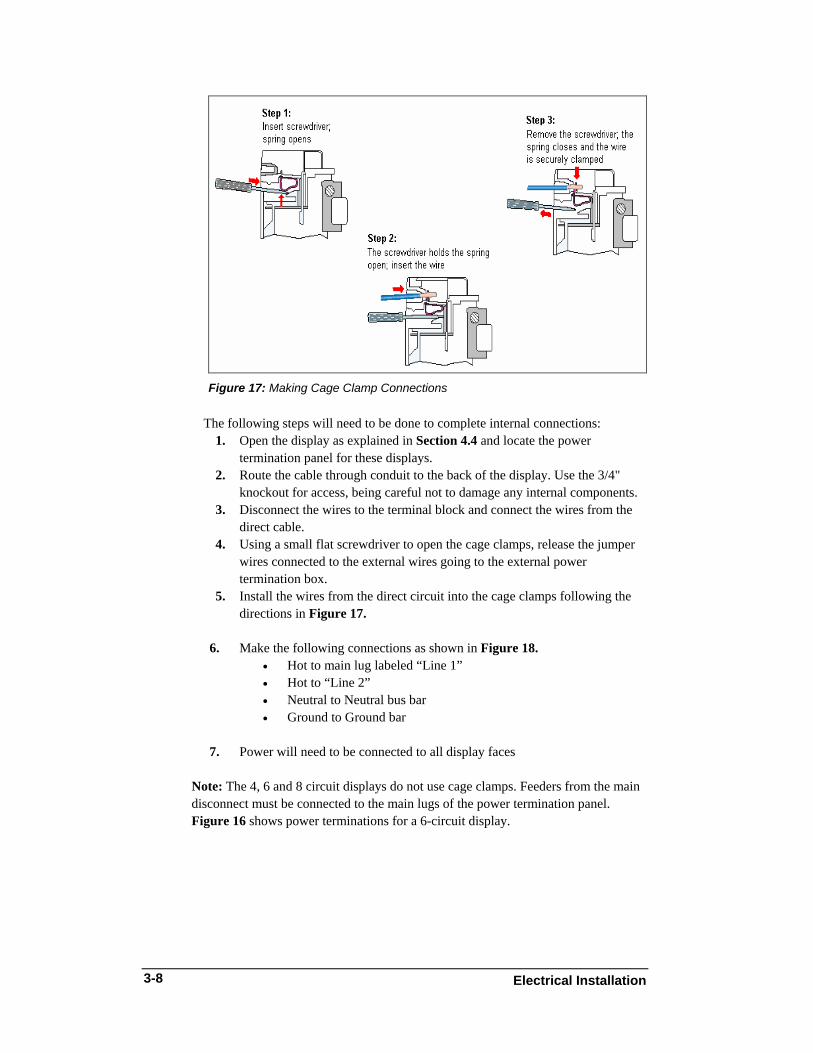
6. Make the following connections as shown in Figure 18.
• Hot to main lug labeled “Line 1” • Hot to “Line 2” • Neutral to Neutral bus bar • Ground to Ground bar
7. Power will need to be connected to all display faces
Note: The 4, 6 and 8 circuit displays do not use cage clamps. Feeders from the main disconnect must be connected to the main lugs of the power termination panel. Figure 16 shows power terminations for a 6-circuit display.
Electrical Installation 3-8
Figure 18: Power Termination Box (4, 6 and 8 Circuit Displays)
Main Disconnect The National Electrical Code requires the use of a lockable power disconnect near the display. Provide a lockable disconnect switch (knife switch) at the display location so that all power lines can be completely disconnected. Use a 3-conductor disconnect so that both hot lines and the neutral line can be disconnected. The main disconnect should be mounted at or near the point of power supply connection to the display. Provide a main disconnect for each supply circuit to the display. Figure 16 illustrates the main disconnect. The disconnecting means must be located in a direct line of sight from the display or outline lighting that it controls. This requirement provides protection by enabling a worker to keep the disconnecting means within view while working on the display. Exception: Disconnecting means that are capable of being locked in the open position may be located elsewhere.
3.7 Signal Termination from Computer to Display The 46 mm, AF-3400 display is designed for quicker signal connection to the display and between displays.
• Signal will terminate to a watertight enclosure that connects to the primary display using a quick connect cable.
• Mount the temperature sensor to the display structure preferably at least one foot away from the display. Terminate it to the primary display with a quick connect cable (Do not mount the temperature sensor between displays or anywhere that the airflow is restricted).
• The primary display connects to the mirror display (2V installations) with a 6-foot quick connect interconnect cable. For cables with right angle connectors, make sure the cable extends to the side or down (never up) to prevent stress on the cable. Flip the end of the cable to switch direction of the right angle end.
Electrical Installation
3-9
A separate manual is provided for explaining the connection to the signal termination enclosure. There are seven different methods of communication; your manual will be one of these types:
Communication
Type Communication
Manual ED# RS232 ED-14739 RS422 ED-14742 Fiber ED-14743 Radio ED-13932
Modem ED-14744 Ethernet ED-14745
Fiber Ethernet ED-14746
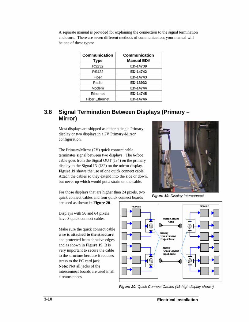
3.8 Signal Termination Between Displays (Primary – Mirror) Most displays are shipped as either a single Primary display or two displays in a 2V Primary-Mirror configuration. The Primary/Mirror (2V) quick connect cable terminates signal between two displays. The 6-foot cable goes from the Signal OUT (J34) on the primary display to the Signal IN (J32) on the mirror display. Figure 19 shows the use of one quick connect cable. Attach the cables so they extend into the side or down, but never up which would put a strain on the cable.
Figure 19: Display Interconnect
For those displays that are higher than 24 pixels, two quick connect cables and four quick connect boards are used as shown in Figure 20.
Displays with 56 and 64 pixels have 3 quick connect cables. Make sure the quick connect cable wire is attached to the structure and protected from abrasive edges and as shown in Figure 19. It is very important to secure the cable to the structure because it reduces stress to the PC card jack. Note: Not all jacks of the interconnect boards are used in all circumstances.
Electrical Installation 3-10
Section 4: Maintenance and Troubleshooting
Important Notes: Power must be turned off before any repair or maintenance work is done on the display.
Qualified service personnel must make any access to internal display electronics. The Daktronics engineering staff must approve ANY changes made to the display. Before altering the display, detailed drawings for the proposed modifications must be submitted to the Daktronics engineering staff for evaluation and approval, or the warranty will be rendered null and void.
4.1 Maintenance and Troubleshooting Overview Daktronics Galaxy® 46 mm, AF-3400 series displays are front accessible meaning access to the internal components can be gained only from the front of the display. This section provides the following Galaxy® display information:
• Signal Routing Summaries provide a basic explanation of the way signal travels through the display.
• Power Routing Summaries offer a basic explanation of the way power travels through the display.
• Service and Diagnostics give instructions for removing various display components, explains the functions of circuit board connectors and the meanings of any diagnostic LEDs.
• Maintenance includes a number of steps to take to keep this Galaxy® display in a safe and working order.
• Troubleshooting lists some possible display malfunctions and provides a number of possible causes for that malfunction.
• Replacement Parts List includes the description and part number of display components that may need replacing during the life of this display.
• Exchange and Repair and Return Programs explain Daktronics component return policy.
Note: A single pixel flashing in the lower right hand corner of the display indicates that the display has power, but no messages are currently running.
Maintenance and Troubleshooting
4-1
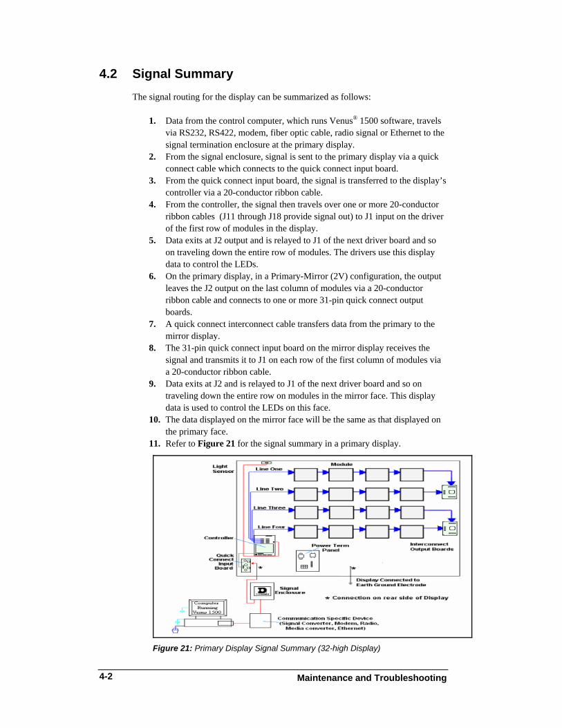
4.2 Signal Summary The signal routing for the display can be summarized as follows:
1. Data from the control computer, which runs Venus® 1500 software, travels via RS232, RS422, modem, fiber optic cable, radio signal or Ethernet to the signal termination enclosure at the primary display.
2. From the signal enclosure, signal is sent to the primary display via a quick connect cable which connects to the quick connect input board.
3. From the quick connect input board, the signal is transferred to the display’s controller via a 20-conductor ribbon cable.
4. From the controller, the signal then travels over one or more 20-conductor ribbon cables (J11 through J18 provide signal out) to J1 input on the driver of the first row of modules in the display.
5. Data exits at J2 output and is relayed to J1 of the next driver board and so on traveling down the entire row of modules. The drivers use this display data to control the LEDs.
6. On the primary display, in a Primary-Mirror (2V) configuration, the output leaves the J2 output on the last column of modules via a 20-conductor ribbon cable and connects to one or more 31-pin quick connect output boards.
7. A quick connect interconnect cable transfers data from the primary to the mirror display.
8. The 31-pin quick connect input board on the mirror display receives the signal and transmits it to J1 on each row of the first column of modules via a 20-conductor ribbon cable.
9. Data exits at J2 and is relayed to J1 of the next driver board and so on traveling down the entire row on modules in the mirror face. This display data is used to control the LEDs on this face.
10. The data displayed on the mirror face will be the same as that displayed on the primary face.
11. Refer to Figure 21 for the signal summary in a primary display.
Figure 21: Primary Display Signal Summary (32-high Display)
Maintenance and Troubleshooting
4-2
4.3 Power Summary
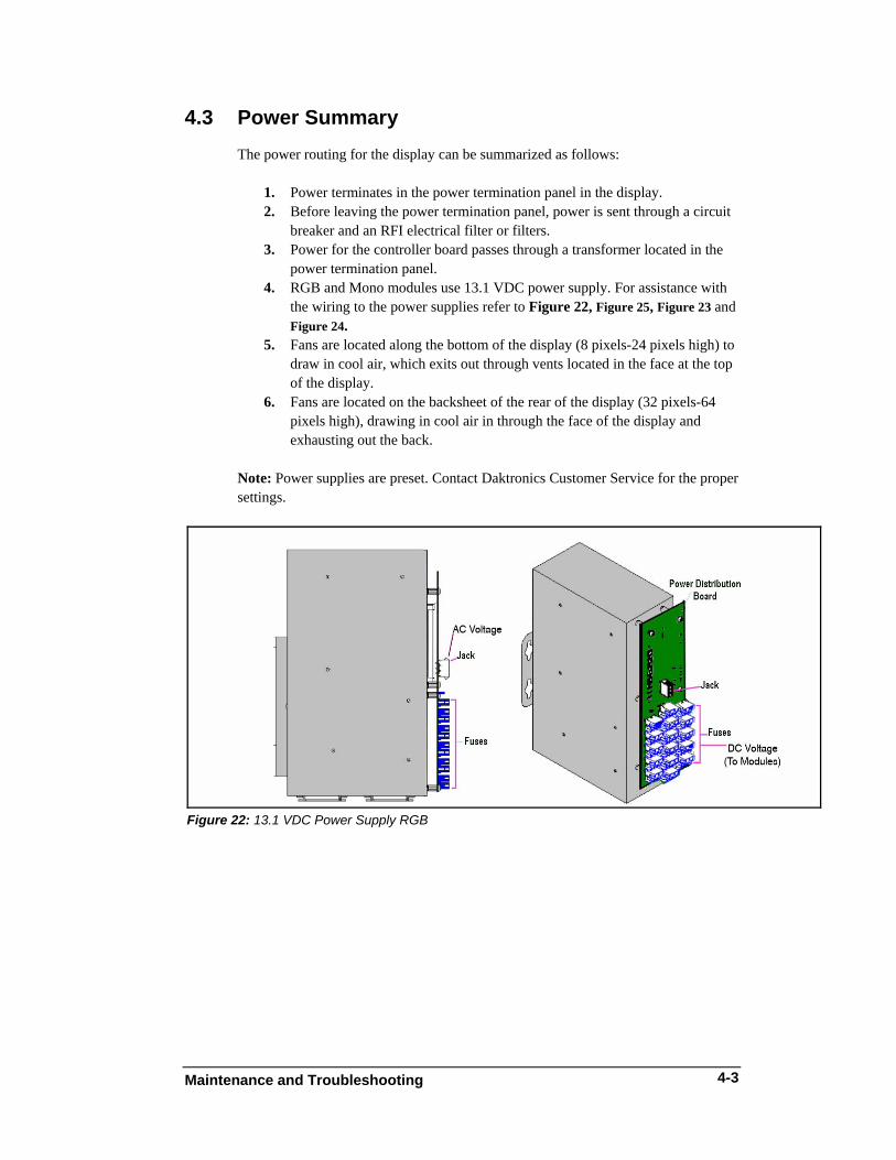
The power routing for the display can be summarized as follows:
1. Power terminates in the power termination panel in the display. 2. Before leaving the power termination panel, power is sent through a circuit
breaker and an RFI electrical filter or filters. 3. Power for the controller board passes through a transformer located in the
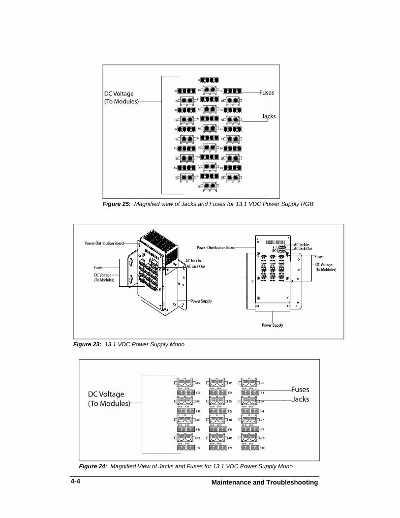
power termination panel. 4. RGB and Mono modules use 13.1 VDC power supply. For assistance with
the wiring to the power supplies refer to Figure 22, Figure 25, Figure 23 and Figure 24.
5. Fans are located along the bottom of the display (8 pixels-24 pixels high) to draw in cool air, which exits out through vents located in the face at the top of the display.
6. Fans are located on the backsheet of the rear of the display (32 pixels-64 pixels high), drawing in cool air in through the face of the display and exhausting out the back.
Note: Power supplies are preset. Contact Daktronics Customer Service for the proper settings.
Figure 22: 13.1 VDC Power Supply RGB
Maintenance and Troubleshooting
4-3
Figure 25: Magnified view of Jacks and Fuses for 13.1 VDC Power Supply RGB
Figure 23: 13.1 VDC Power Supply Mono
Figure 24: Magnified View of Jacks and Fuses for 13.1 VDC Power Supply Mono
Maintenance and Troubleshooting
4-4
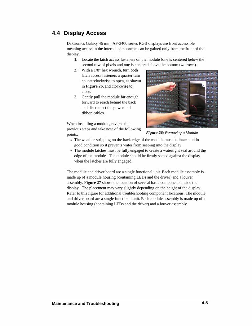
4.4 Display Access Daktronics Galaxy 46 mm, AF-3400 series RGB displays are front accessible meaning access to the internal components can be gained only from the front of the display.
1. Locate the latch access fasteners on the module (one is centered below the second row of pixels and one is centered above the bottom two rows).
2. With a 1/8" hex wrench, turn both latch access fasteners a quarter turn counterclockwise to open, as shown in Figure 26, and clockwise to close.
Figure 26: Removing a Module
3. Gently pull the module far enough forward to reach behind the back and disconnect the power and ribbon cables.
When installing a module, reverse the previous steps and take note of the following points.
• The weather-stripping on the back edge of the module must be intact and in good condition so it prevents water from seeping into the display.
• The module latches must be fully engaged to create a watertight seal around the edge of the module. The module should be firmly seated against the display when the latches are fully engaged.
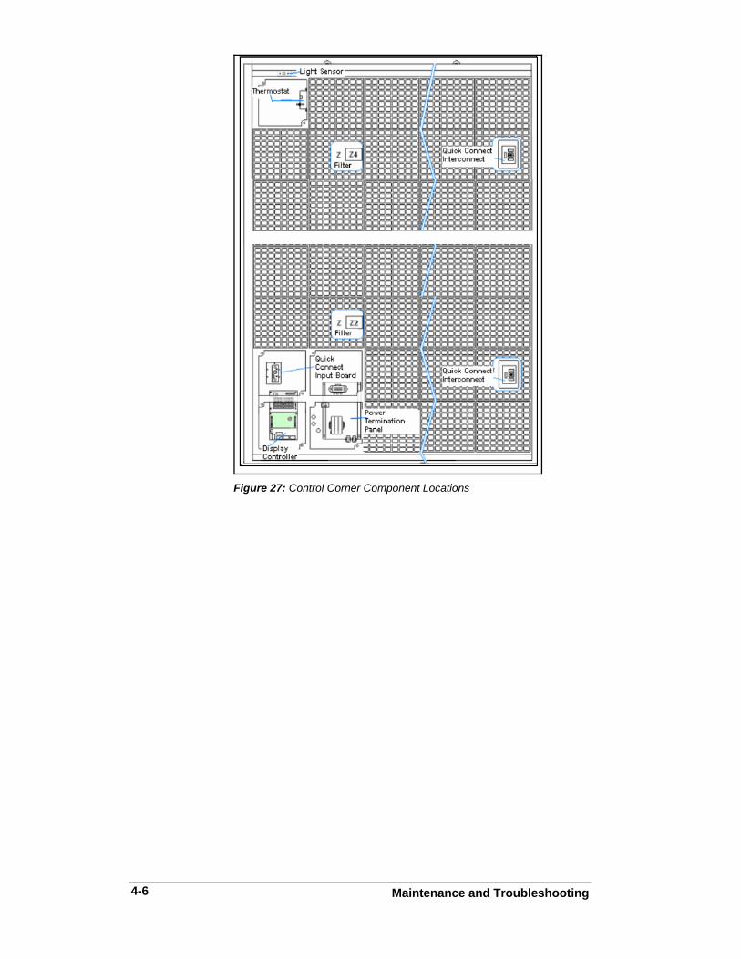
The module and driver board are a single functional unit. Each module assembly is made up of a module housing (containing LEDs and the driver) and a louver assembly. Figure 27 shows the location of several basic components inside the display. The placement may vary slightly depending on the height of the display. Refer to this figure for additional troubleshooting component locations. The module and driver board are a single functional unit. Each module assembly is made up of a module housing (containing LEDs and the driver) and a louver assembly.
Maintenance and Troubleshooting
4-5
Figure 27: Control Corner Component Locations
Maintenance and Troubleshooting
4-6
Maintenance and Troubleshooting
4-7
4.5 Service and Diagnostics Reference Drawings:
Schematics............................................................... Refer to Appendix A
The following sub-sections address servicing of the following display components:
• Transformer, RFI filter • Controller • Power supplies
The sub-sections also address any diagnostic LEDs, fuses, and signal/power connectors found on the unit. On the Schematics the components are denoted as follows:
Schematic, Power Term Panel, 1 Circuit...............................Drawing A-211950 Schematic, Power Term Panel, 2 Circuit...............................Drawing A-211947 Schematic, Power Term Panel, 4&6 Circuit, 120/240 V........Drawing A-223673 Schematic, Power Term Panel, 8 Circuit, 120/240V .............Drawing A-231469
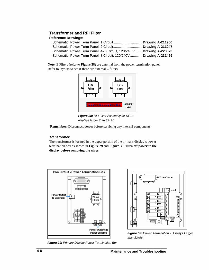
Note: Z Filters (refer to Figure 28) are external from the power termination panel. Refer to layouts to see if there are external Z filters.
Figure 28: RFI Filter Assembly for RGB displays larger than 32x96
Remember: Disconnect power before servicing any internal components
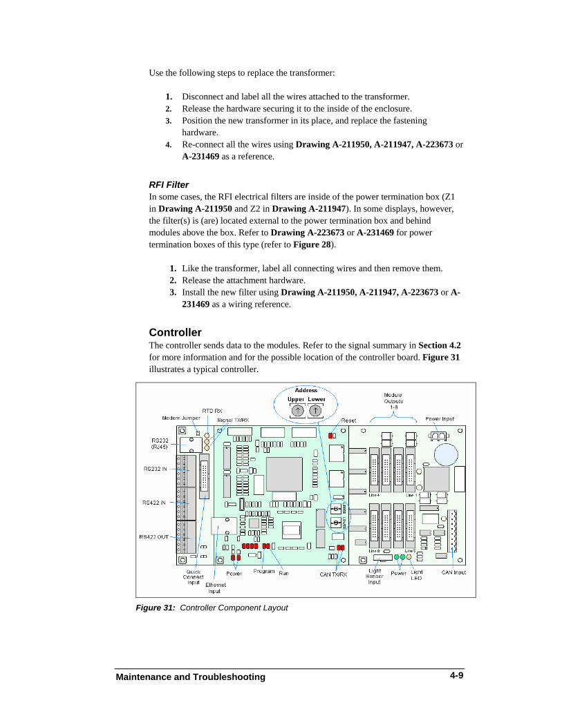
Transformer The transformer is located in the upper portion of the primary display’s power termination box as shown in Figure 29 and Figure 30. Turn off power to the display before removing the wires.
Figure 29: Primary Display Power Termination Box
Figure 30: Power Termination - Displays Larger than 32x96
Maintenance and Troubleshooting
4-8
Use the following steps to replace the transformer:
1. Disconnect and label all the wires attached to the transformer. 2. Release the hardware securing it to the inside of the enclosure. 3. Position the new transformer in its place, and replace the fastening
hardware. 4. Re-connect all the wires using Drawing A-211950, A-211947, A-223673 or
A-231469 as a reference.
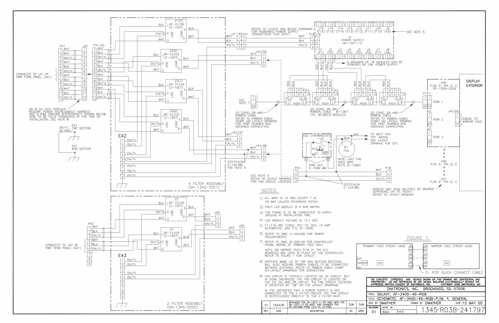
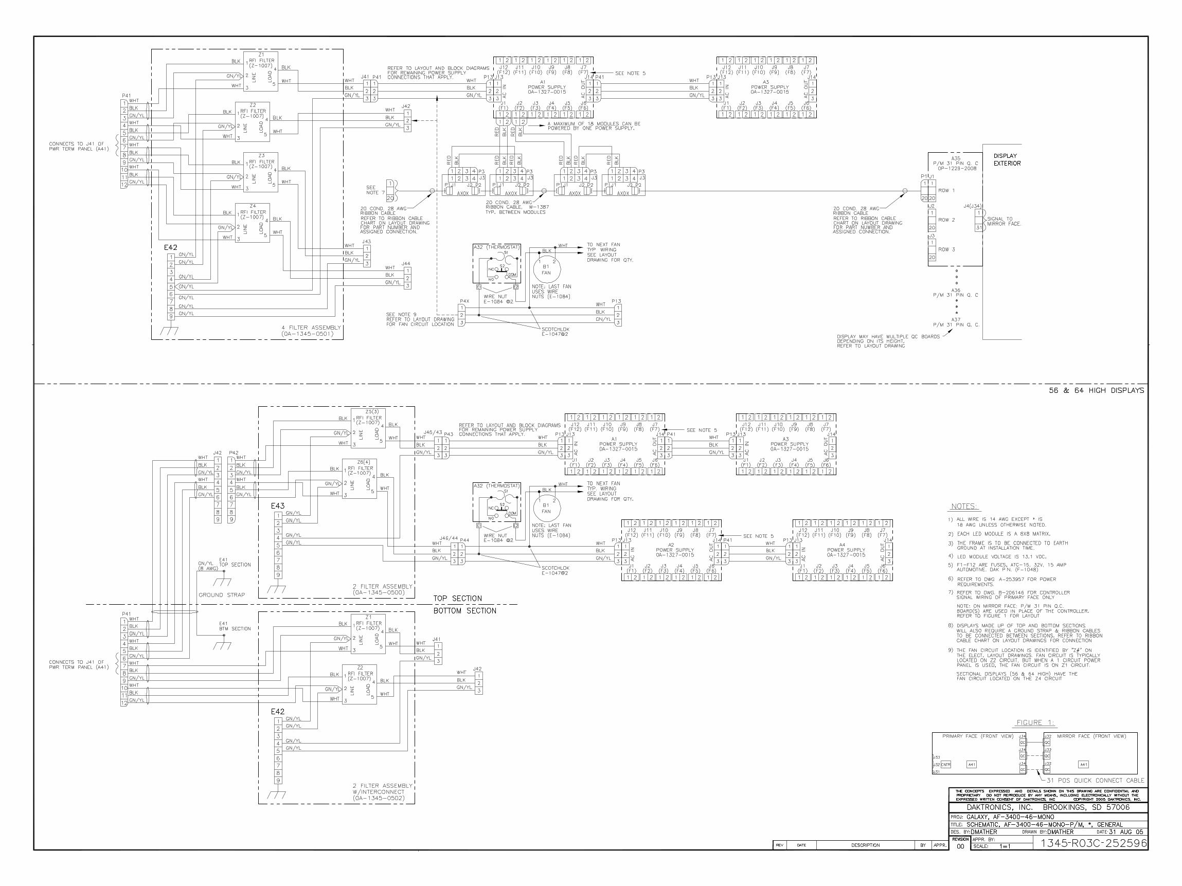
RFI Filter In some cases, the RFI electrical filters are inside of the power termination box (Z1 in Drawing A-211950 and Z2 in Drawing A-211947). In some displays, however, the filter(s) is (are) located external to the power termination box and behind modules above the box. Refer to Drawing A-223673 or A-231469 for power termination boxes of this type (refer to Figure 28).
1. Like the transformer, label all connecting wires and then remove them. 2. Release the attachment hardware. 3. Install the new filter using Drawing A-211950, A-211947, A-223673 or A-
231469 as a wiring reference.
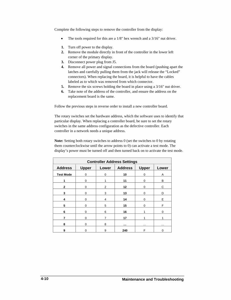
Controller
The controller sends data to the modules. Refer to the signal summary in Section 4.2 for more information and for the possible location of the controller board. Figure 31 illustrates a typical controller.
Figure 31: Controller Component Layout
Maintenance and Troubleshooting
4-9
Maintenance and Troubleshooting
4-10
Complete the following steps to remove the controller from the display: • The tools required for this are a 1/8" hex wrench and a 3/16" nut driver.
1. Turn off power to the display. 2. Remove the module directly in front of the controller in the lower left
corner of the primary display. 3. Disconnect power plug from J5. 4. Remove all power and signal connections from the board (pushing apart the
latches and carefully pulling them from the jack will release the “Locked” connectors). When replacing the board, it is helpful to have the cables labeled as to which was removed from which connector.
5. Remove the six screws holding the board in place using a 3/16" nut driver. 6. Take note of the address of the controller, and ensure the address on the
replacement board is the same.
Follow the previous steps in reverse order to install a new controller board. The rotary switches set the hardware address, which the software uses to identify that particular display. When replacing a controller board, be sure to set the rotary switches in the same address configuration as the defective controller. Each controller in a network needs a unique address. Note: Setting both rotary switches to address 0 (set the switches to 0 by rotating them counterclockwise until the arrow points to 0) can activate a test mode. The display’s power must be turned off and then turned back on to activate the test mode.
Controller Address Settings Address Upper Lower Address Upper Lower Test Mode 0 0 10 0 A
1 0 1 11 0 B
2 0 2 12 0 C
3 0 3 13 0 D
4 0 4 14 0 E
5 0 5 15 0 F
6 0 6 16 1 0
7 0 7 17 1 1
8 0 8 … … …
9 0 9 240 F 0
Maintenance and Troubleshooting
4-11
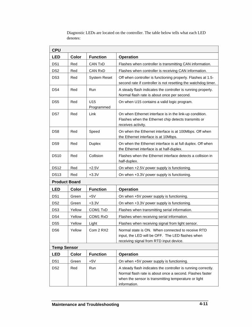
Diagnostic LEDs are located on the controller. The table below tells what each LED denotes:
CPU LED Color Function Operation DS1 Red CAN TxD Flashes when controller is transmitting CAN information.
DS2 Red CAN RxD Flashes when controller is receiving CAN information.
DS3 Red System Reset Off when controller is functioning properly. Flashes at 1.5-second rate if controller is not resetting the watchdog timer.
DS4 Red Run A steady flash indicates the controller is running properly. Normal flash rate is about once per second.
DS5 Red U15 Programmed
On when U15 contains a valid logic program.
DS7 Red Link On when Ethernet interface is in the link-up condition. Flashes when the Ethernet chip detects transmits or receives activity.
DS8 Red Speed On when the Ethernet interface is at 100Mbps. Off when the Ethernet interface is at 10Mbps.
DS9 Red Duplex On when the Ethernet interface is at full duplex. Off when the Ethernet interface is at half-duplex.
DS10 Red Collision Flashes when the Ethernet interface detects a collision in half-duplex.
DS12 Red +2.5V On when +2.5V power supply is functioning.
DS13 Red +3.3V On when +3.3V power supply is functioning.
Product Board
LED Color Function Operation DS1 Green +5V On when +5V power supply is functioning.
DS2 Green +3.3V On when +3.3V power supply is functioning.
DS3 Yellow COM1 TxD Flashes when transmitting serial information.
DS4 Yellow COM1 RxD Flashes when receiving serial information.
DS5 Yellow Light Flashes when receiving signal from light sensor.
DS6 Yellow Com 2 RX2 Normal state is ON. When connected to receive RTD input, the LED will be OFF. The LED flashes when receiving signal from RTD input device.
Temp Sensor LED Color Function Operation DS1 Green +5V On when +5V power supply is functioning.
DS2 Red Run A steady flash indicates the controller is running correctly. Normal flash rate is about once a second. Flashes faster when the sensor is transmitting temperature or light information.
Maintenance and Troubleshooting
4-12
Power Supplies The LED power supplies are identified as assemblies. Each power supply unit can power up to eighteen modules.
The 46 mm, AF-3400 Galaxy displays use red, green and blue LEDs for the color for RGB displays and red or amber for the Mono displays.
• Each 13.1 VDC power supply provides power for up to eighteen
modules in a RGB display. Refer to Figure 22, Figure 25, Figure 23 and Figure 24 for the 13.1 VDC power display illustration.
4.6 Ventilation Systems Ventilation fans should be checked after 1,500 hours of operation and every 1,500 hours after that to ensure the display is being cooled properly. Fans should be checked more often if the display is located in a dusty or harsh weather environment (i.e. along a gravel road with dust laden air).
• 1,500 hours is equivalent to 83 days if the display is operated for 18 hours a day, and the power to the display is turned off when not in use.
• 1,500 hours is equivalent to 62 days if the display is running non-stop for 24 hours a day.
• Each time a module is removed, take a minute to inspect the fans. • Check the fan blades for dirt and debris. If necessary, clean them and the
inside of the display. Fan blades must be kept clean to maintain fan efficiency and ensure proper cooling.
• Spin the fan blades with a pen or pencil to ensure that the bearings are free and the fan is still in balance.
To check the operation of the fans, push the bypass button (momentary contact) on the thermostat enclosure to temporarily turn the fans on (the bypass button is located behind A101, top row and first module on the left).
• Hold your hand or a piece of light paper in front of the display to detect air movement.
• If the fan does not turn or does not operate smoothly, replace it. Make sure the intake vents and exhaust vents on the front of the display are not blocked and are free of dust or other debris.
4.7 Thermostats A thermostat controls the operation of the ventilation fans in the display. The thermostat is typically located behind module A101 as shown in Figure 27. The ventilation fans turn on when the inside of the display reaches 85° F (29° C) and turn off at 65° F (21° C).
Maintenance and Troubleshooting
4-13
4.8 Weather-stripping To ensure that the display is waterproof, weather-stripping has been provided around the entire display and around each module. It is important that the weather-stripping is installed properly at all times or water may leak into the display and damage the components.
4.9 Display Maintenance A yearly inspection should be completed to maintain safe and dependable display operation. This inspection should address the following issues:
• Loose Hardware Verify fasteners, such as bolts and rivets, have not come loose. Fasteners
should be checked and tightened or replaced as required. • Excessive Dust Buildup Occasionally it may be necessary to vacuum the inside of the display
cabinet to remove dust/dirt buildup that may interfere with airflow. • Water Intrusion – Water Stain Marks Water can enter the display where weather-stripping has come loose or
deteriorated, where fasteners have come loose allowing gaps in the panels or where moisture may be entering around hardware. Be sure to check around the lift eyes and bolts to ensure that water has not entered there. If it has, replace hardware immediately to prevent more water from entering the display. Also, check electronic components for possible corrosion.
• Corrosion Check the paint, and look for possible corrosion especially at footings,
structural tie points and ground rods. If any of the above conditions are noticed, action must be taken to correct the situation.
Maintenance and Troubleshooting
4-14
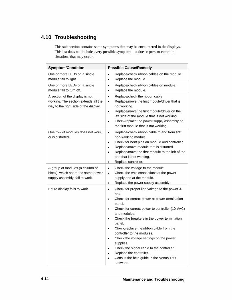
4.10 Troubleshooting This sub-section contains some symptoms that may be encountered in the displays. This list does not include every possible symptom, but does represent common situations that may occur.
Symptom/Condition Possible Cause/Remedy One or more LEDs on a single module fail to light.
• Replace/check ribbon cables on the module. • Replace the module.
One or more LEDs on a single module fail to turn off.
• Replace/check ribbon cables on module. • Replace the module.
A section of the display is not working. The section extends all the way to the right side of the display.
• Replace/check the ribbon cable. • Replace/move the first module/driver that is
not working. • Replace/move the first module/driver on the
left side of the module that is not working. • Check/replace the power supply assembly on
the first module that is not working.
One row of modules does not work or is distorted.
• Replace/check ribbon cable to and from first non-working module.
• Check for bent pins on module and controller. • Replace/move module that is distorted. • Replace/move the first module to the left of the
one that is not working. • Replace controller.
A group of modules (a column of block), which share the same power supply assembly, fail to work.
• Check the voltage to the module. • Check the wire connections at the power
supply and at the module. • Replace the power supply assembly.
Entire display fails to work. • Check for proper line voltage to the power J-box.
• Check for correct power at power termination panel.
• Check for correct power to controller (10 VAC) and modules.
• Check the breakers in the power termination panel.
• Check/replace the ribbon cable from the controller to the modules.
• Check the voltage settings on the power supplies.
• Check the signal cable to the controller. • Replace the controller. • Consult the help guide in the Venus 1500
software.
Maintenance and Troubleshooting
4-15
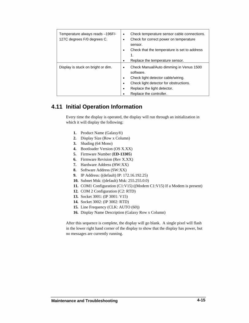
Temperature always reads –196F/-127C degrees F/0 degrees C.
• Check temperature sensor cable connections. • Check for correct power on temperature
sensor. • Check that the temperature is set to address
1. • Replace the temperature sensor.
Display is stuck on bright or dim. • Check Manual/Auto dimming in Venus 1500 software.
• Check light detector cable/wiring. • Check light detector for obstructions. • Replace the light detector. • Replace the controller.
4.11 Initial Operation Information Every time the display is operated, the display will run through an initialization in which it will display the following:
1. Product Name (Galaxy®) 2. Display Size (Row x Column) 3. Shading (64 Mono) 4. Bootloader Version (OS X.XX) 5. Firmware Number (ED-13305) 6. Firmware Revision (Rev X.XX) 7. Hardware Address (HW:XX) 8. Software Address (SW:XX) 9. IP Address: ((default) IP: 172.16.192.25) 10. Subnet Msk: ((default) Msk: 255.255.0.0) 11. COM1 Configuration (C1:V15) ((Modem C1:V15) If a Modem is present) 12. COM 2 Configuration (C2: RTD) 13. Socket 3001: (IP 3001: V15) 14. Socket 3002: (IP 3002: RTD) 15. Line Frequency (CLK: AUTO (60)) 16. Display Name Description (Galaxy Row x Column)
After this sequence is complete, the display will go blank. A single pixel will flash in the lower right hand corner of the display to show that the display has power, but no messages are currently running.
Maintenance and Troubleshooting
4-16
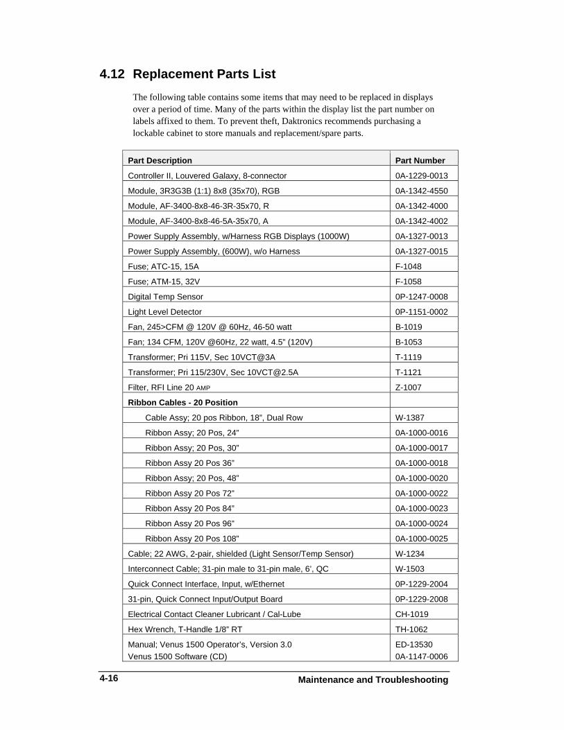
4.12 Replacement Parts List The following table contains some items that may need to be replaced in displays over a period of time. Many of the parts within the display list the part number on labels affixed to them. To prevent theft, Daktronics recommends purchasing a lockable cabinet to store manuals and replacement/spare parts.
Part Description Part Number
Controller II, Louvered Galaxy, 8-connector 0A-1229-0013
4.13 Daktronics Exchange and Repair & Return Programs To serve customers’ repair and maintenance needs, Daktronics offers both an Exchange Program and a Repair & Return Program.
Exchange Program Daktronics unique Exchange Program is a quick service for replacing key parts in need of repair. If a part requires repair or replacement, Daktronics sends the customer a replacement, and the customer sends the defective part to Daktronics. This decreases display downtime.
Before Contacting Daktronics Insert important part numbers here: _____________________________________________________________ _____________________________________________________________ _____________________________________________________________
Display Serial Number: ______________________________________________ Display Model Number: ______________________________________________ Contract Number: __________________________________________________ Date Installed: _____________________________________________________ Daktronics Customer ID Number: ______________________________________
To participate in the Exchange Program, follow these steps.
1. Call Daktronics Customer Service: 866-343-3122
2. When the new exchange part is received, mail the old part to Daktronics. If the replacement part fixes the problem, send in the problem part which is being replaced. a. Package the old part in the same shipping materials in which the
replacement part arrived. b. Fill out and attach the enclosed UPS shipping document. c. Ship the part to Daktronics.
3. A charge will be made for the replacement part immediately, unless a
qualifying service agreement is in place. In most circumstances, the replacement part will be invoiced at the time it is shipped.
4. If the replacement part does not solve the problem, return the part
within 30 working days or the full purchase price will be charged. If, after the exchange is made the equipment is still defective, please contact Customer Service immediately. Daktronics expects immediate return of an exchange part if it does not solve the problem. The company also reserves
Maintenance and Troubleshooting
4-18
the right to refuse parts that have been damaged due to acts of nature or causes other than normal wear and tear.
Repair & Return Program For items not subject to exchange, Daktronics offers a Repair & Return Program. To send a part for repair, follow these steps:
1. Call or fax Daktronics Customer Service:
Phone: 866-343-3122 Fax: 605-697-4444
2. Receive a Return Materials Authorization (RMA) number before shipping. This expedites repair of the part.
3. Package and pad the item carefully to prevent damage during
shipment. Electronic components, such as printed circuit boards, should be placed in an antistatic bag before boxing. Daktronics does not recommend styrofoam peanuts in packaging.
4. Enclose:
• your name • address • phone number • the RMA number • a clear description of symptoms
Shipping Address Daktronics Customer Service PO Box 5128 331 32nd Ave Brookings, SD 57006
Reference Drawings
B-1
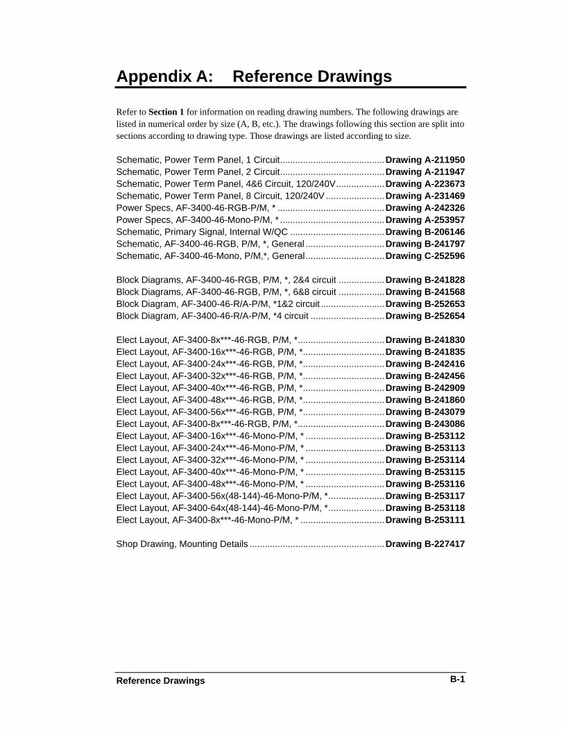
Appendix A: Reference Drawings
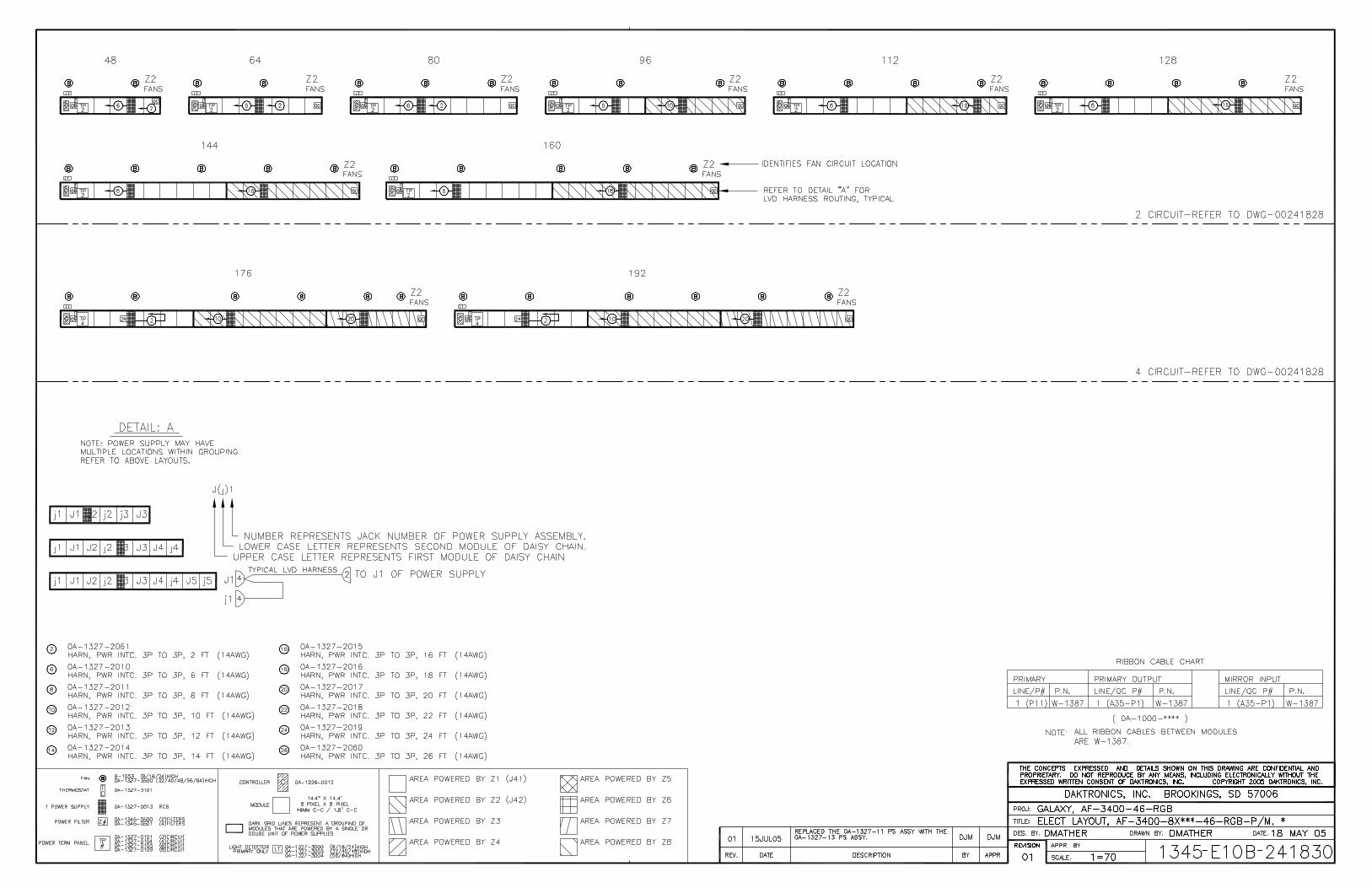
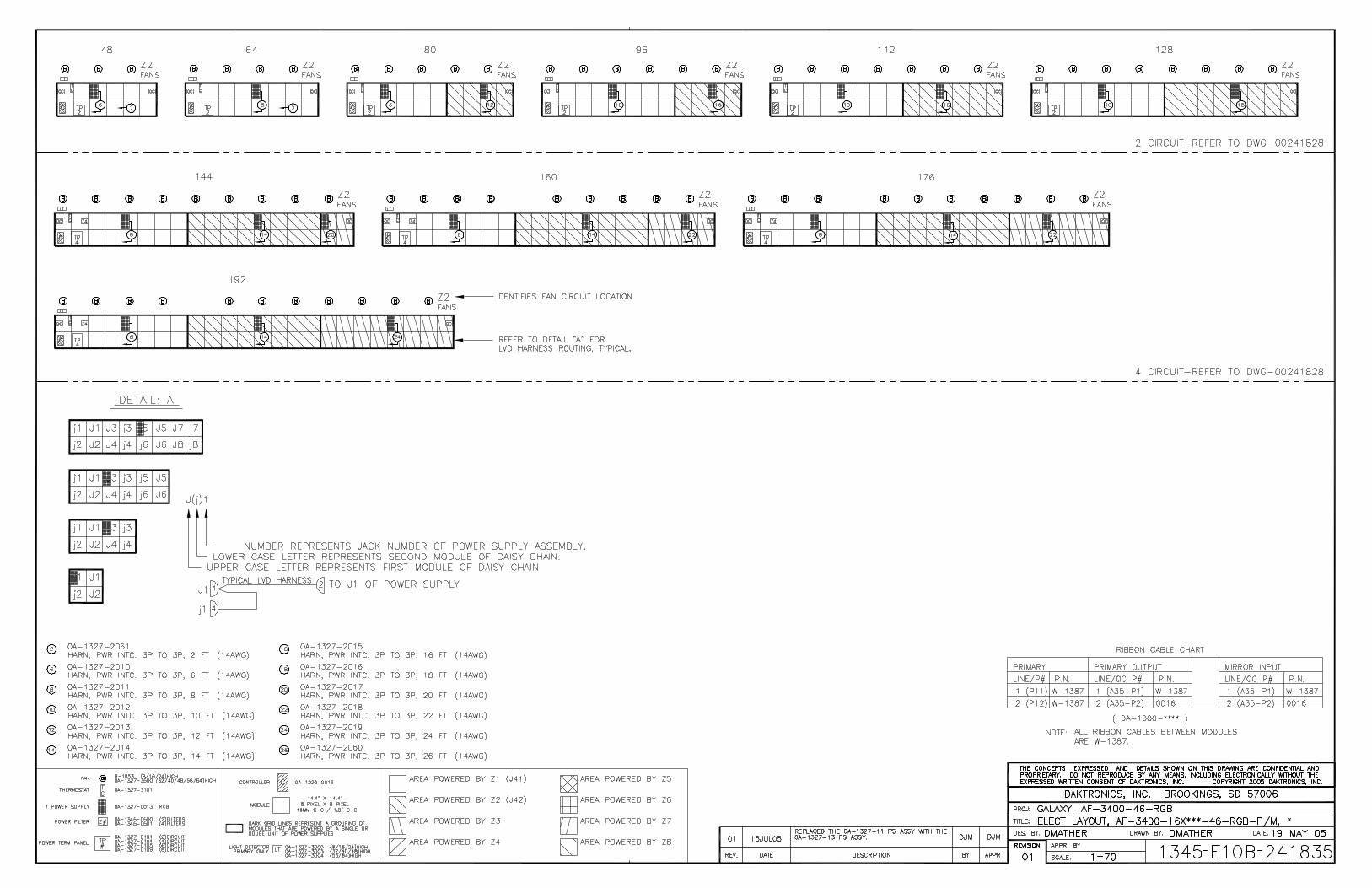
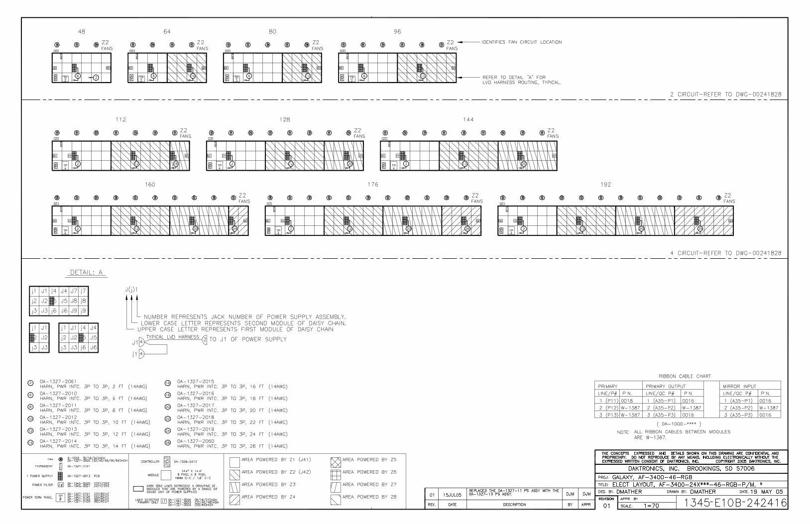
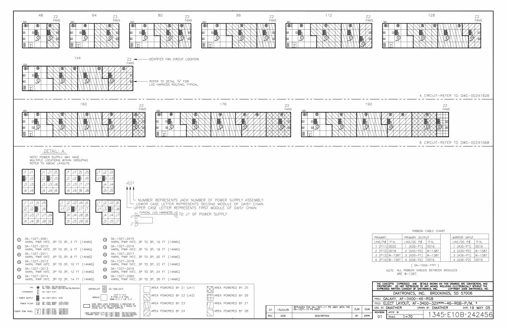
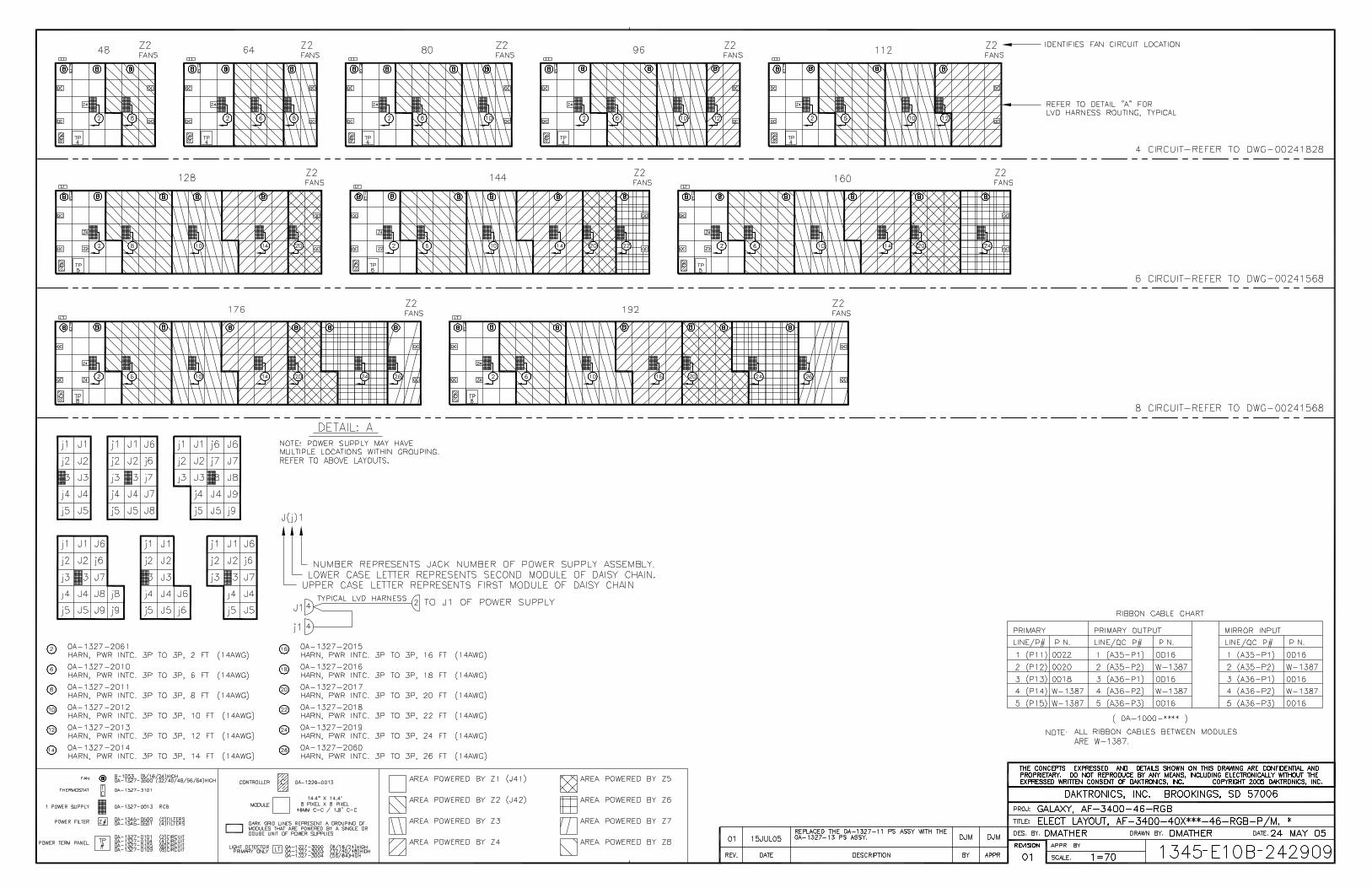
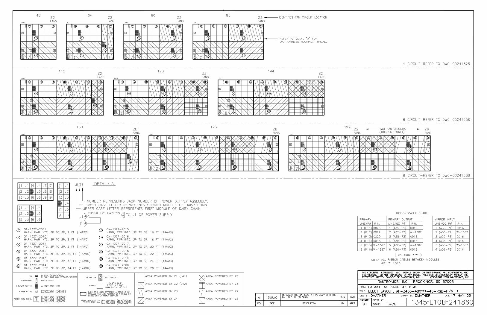
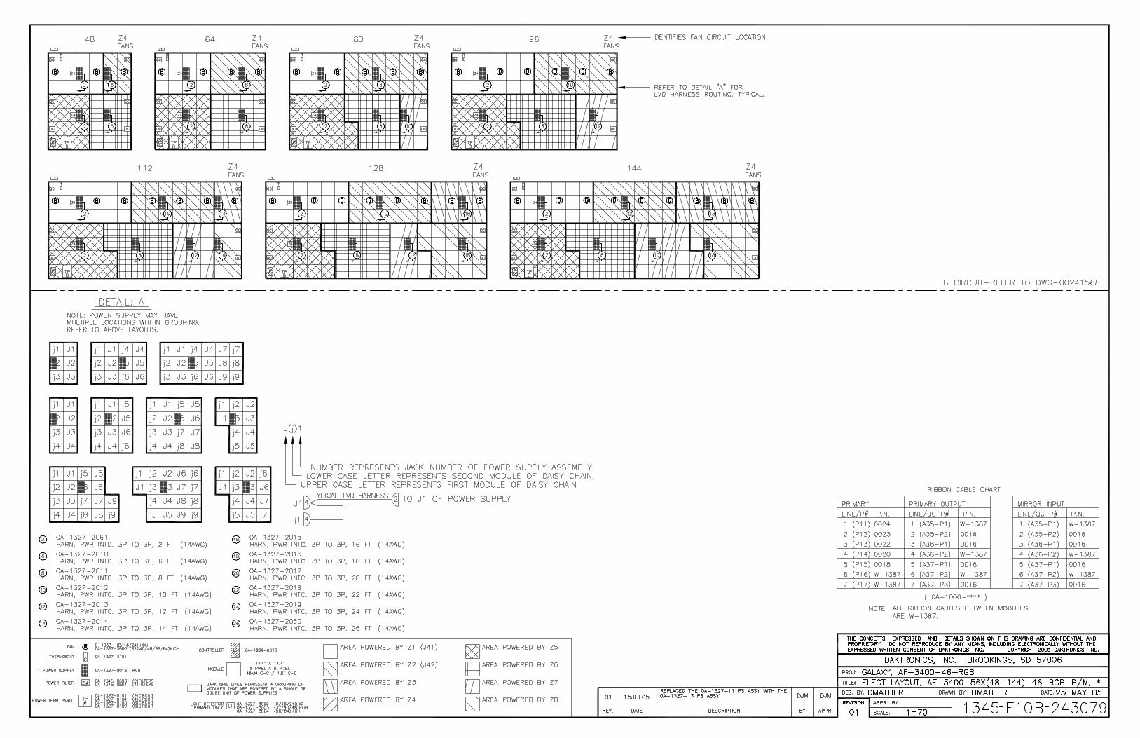
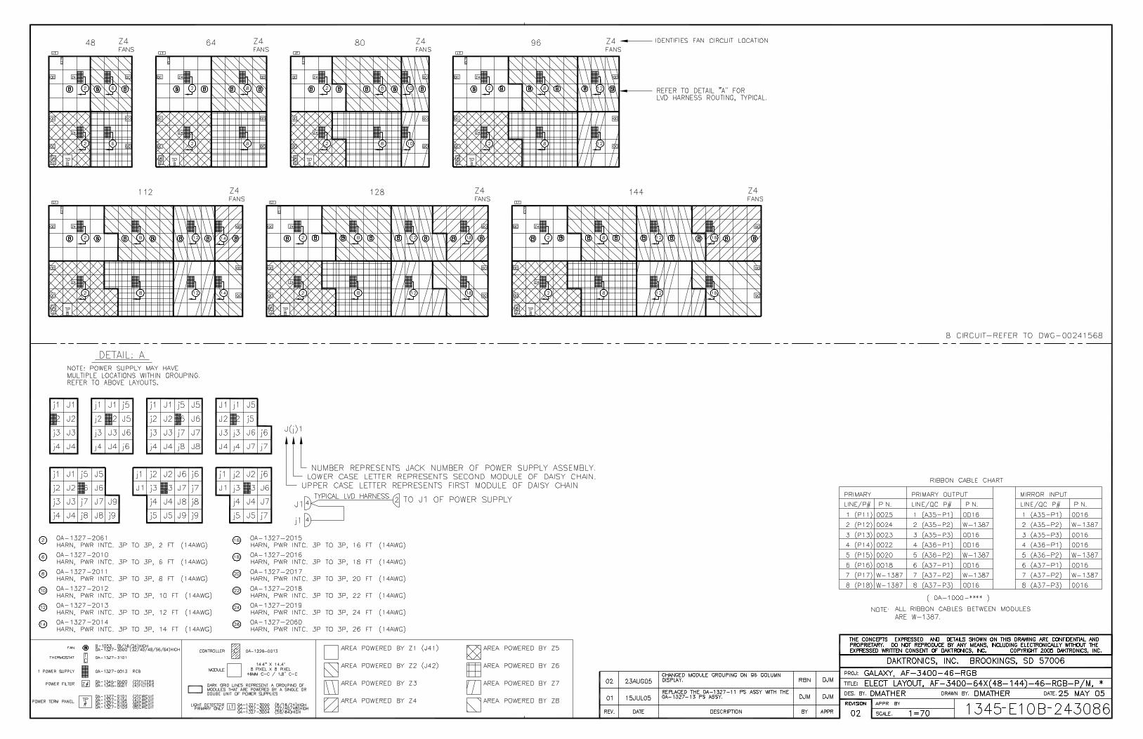
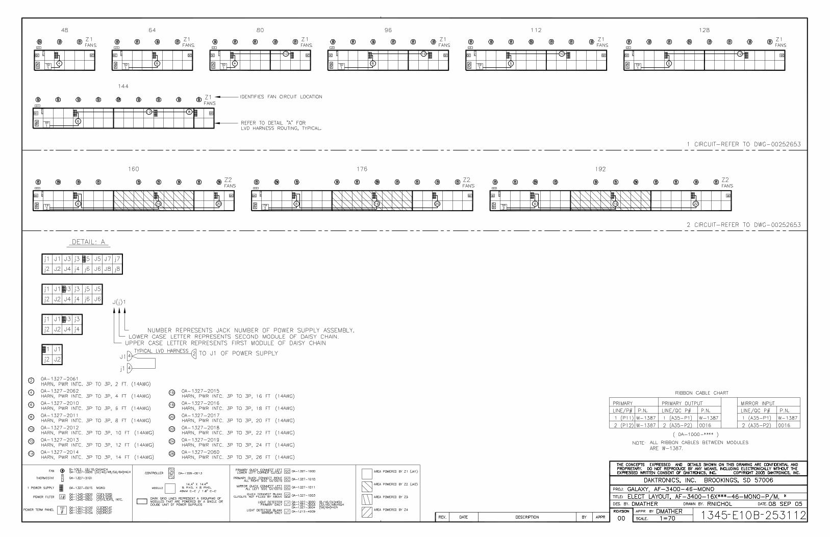
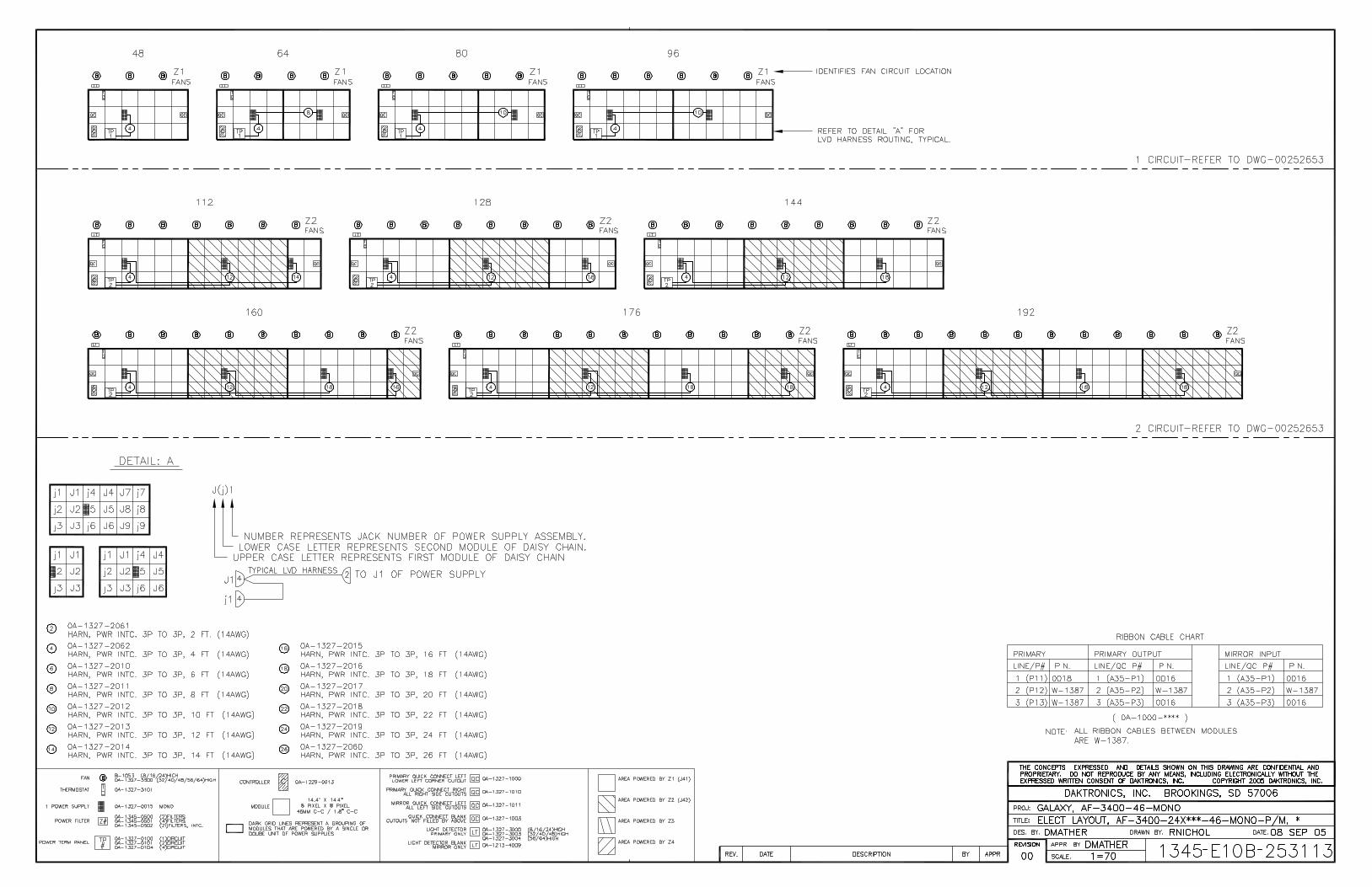
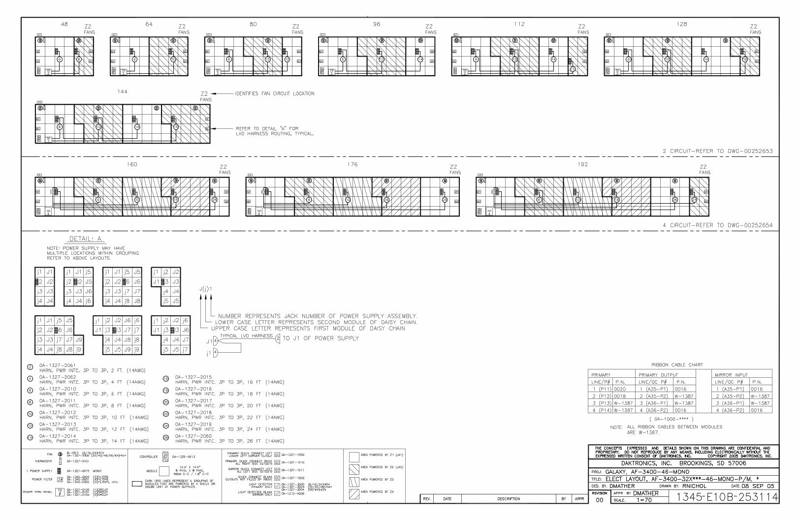
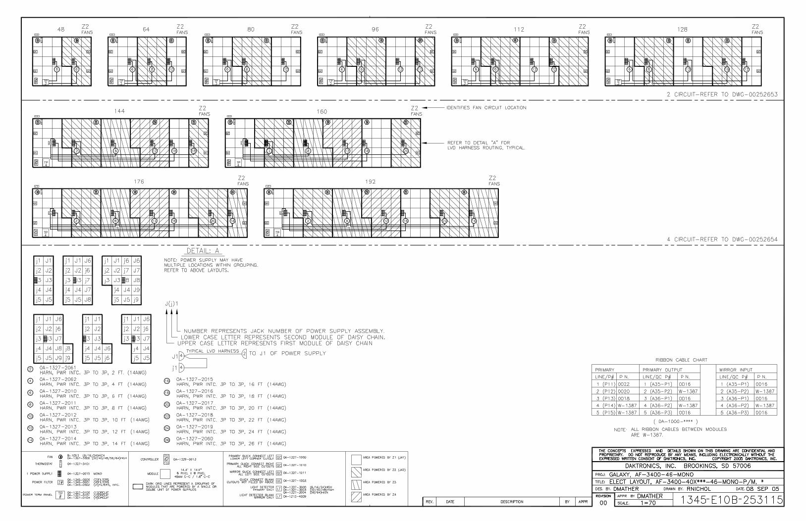
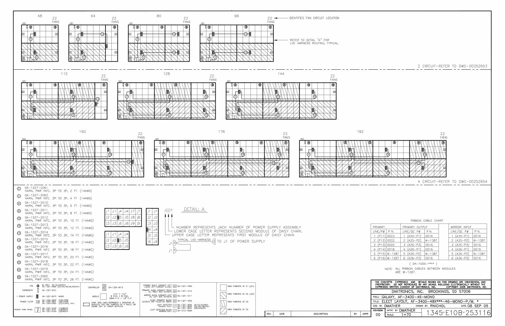
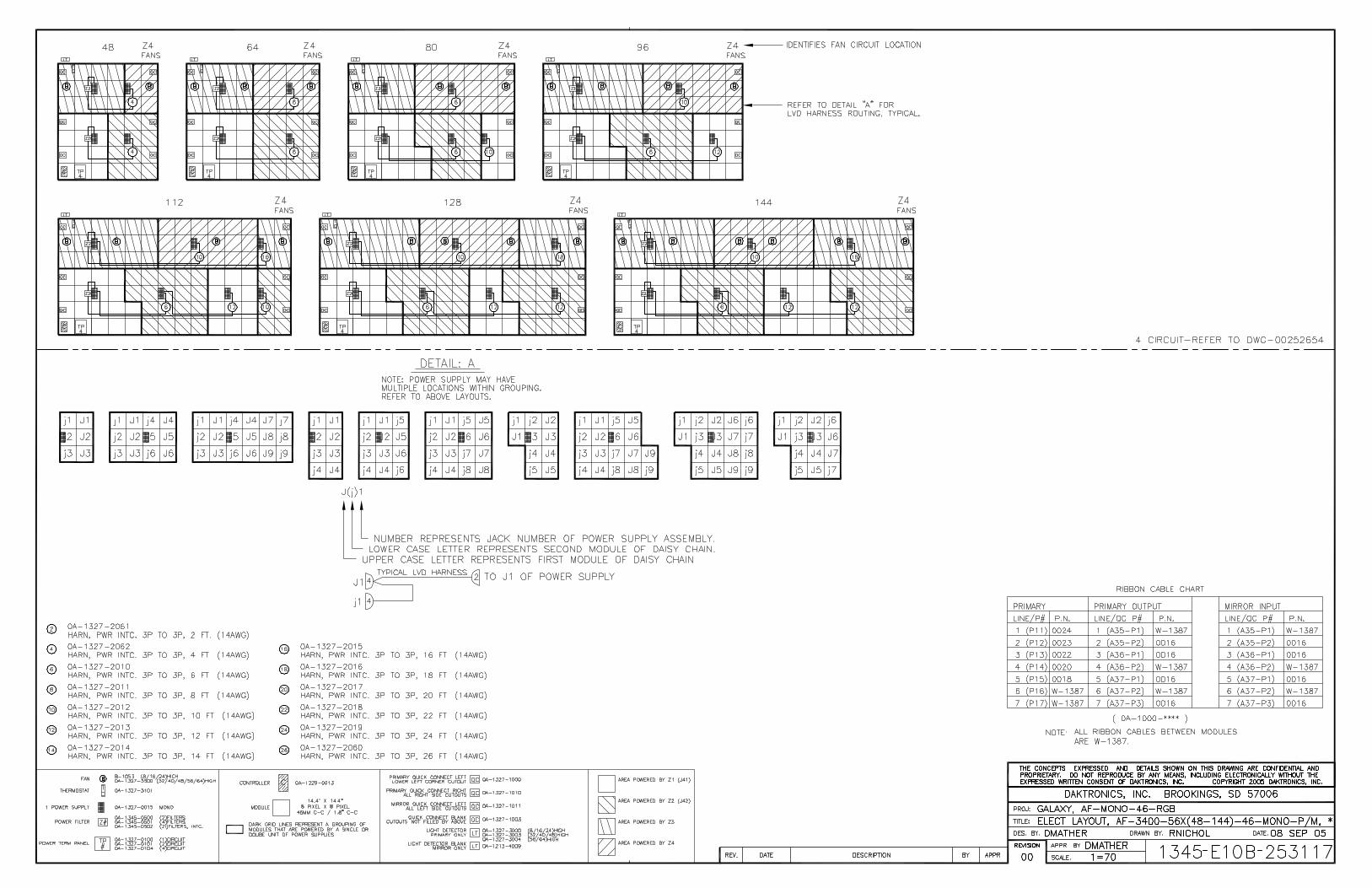
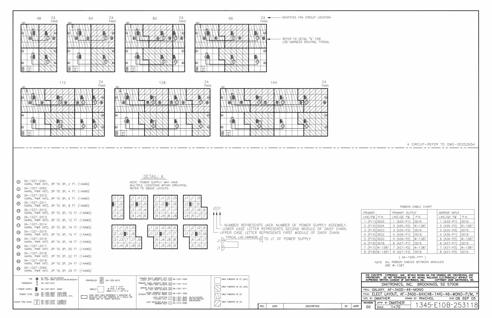
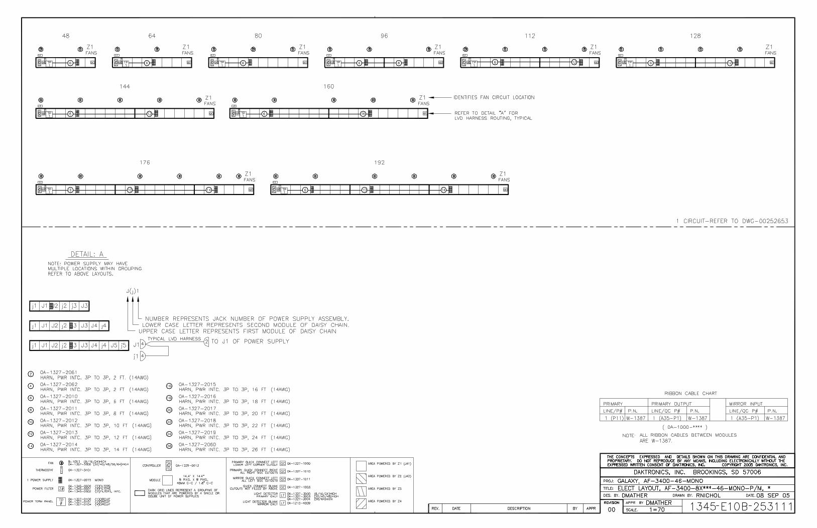
Refer to Section 1 for information on reading drawing numbers. The following drawings are listed in numerical order by size (A, B, etc.). The drawings following this section are split into sections according to drawing type. Those drawings are listed according to size. Schematic, Power Term Panel, 1 Circuit.........................................Drawing A-211950 Schematic, Power Term Panel, 2 Circuit.........................................Drawing A-211947 Schematic, Power Term Panel, 4&6 Circuit, 120/240V...................Drawing A-223673 Schematic, Power Term Panel, 8 Circuit, 120/240V .......................Drawing A-231469 Power Specs, AF-3400-46-RGB-P/M, * ..........................................Drawing A-242326 Power Specs, AF-3400-46-Mono-P/M, * .........................................Drawing A-253957 Schematic, Primary Signal, Internal W/QC .....................................Drawing B-206146 Schematic, AF-3400-46-RGB, P/M, *, General ...............................Drawing B-241797 Schematic, AF-3400-46-Mono, P/M,*, General...............................Drawing C-252596 Block Diagrams, AF-3400-46-RGB, P/M, *, 2&4 circuit ..................Drawing B-241828 Block Diagrams, AF-3400-46-RGB, P/M, *, 6&8 circuit ..................Drawing B-241568 Block Diagram, AF-3400-46-R/A-P/M, *1&2 circuit .........................Drawing B-252653 Block Diagram, AF-3400-46-R/A-P/M, *4 circuit .............................Drawing B-252654 Elect Layout, AF-3400-8x***-46-RGB, P/M, *..................................Drawing B-241830 Elect Layout, AF-3400-16x***-46-RGB, P/M, *................................Drawing B-241835 Elect Layout, AF-3400-24x***-46-RGB, P/M, *................................Drawing B-242416 Elect Layout, AF-3400-32x***-46-RGB, P/M, *................................Drawing B-242456 Elect Layout, AF-3400-40x***-46-RGB, P/M, *................................Drawing B-242909 Elect Layout, AF-3400-48x***-46-RGB, P/M, *................................Drawing B-241860 Elect Layout, AF-3400-56x***-46-RGB, P/M, *................................Drawing B-243079 Elect Layout, AF-3400-8x***-46-RGB, P/M, *..................................Drawing B-243086 Elect Layout, AF-3400-16x***-46-Mono-P/M, * ...............................Drawing B-253112 Elect Layout, AF-3400-24x***-46-Mono-P/M, * ...............................Drawing B-253113 Elect Layout, AF-3400-32x***-46-Mono-P/M, * ...............................Drawing B-253114 Elect Layout, AF-3400-40x***-46-Mono-P/M, * ...............................Drawing B-253115 Elect Layout, AF-3400-48x***-46-Mono-P/M, * ...............................Drawing B-253116 Elect Layout, AF-3400-56x(48-144)-46-Mono-P/M, *......................Drawing B-253117 Elect Layout, AF-3400-64x(48-144)-46-Mono-P/M, *......................Drawing B-253118 Elect Layout, AF-3400-8x***-46-Mono-P/M, * .................................Drawing B-253111 Shop Drawing, Mounting Details .....................................................Drawing B-227417
Appendix B: Optional Temp Sensors
B-1
Appendix B: Optional Temperature Sensor
p. 1 of 6 Optional Temperature Sensor Mounting
ED-14377-Rev 4 3 October 2007
For Galaxy displays only Reference Drawings:
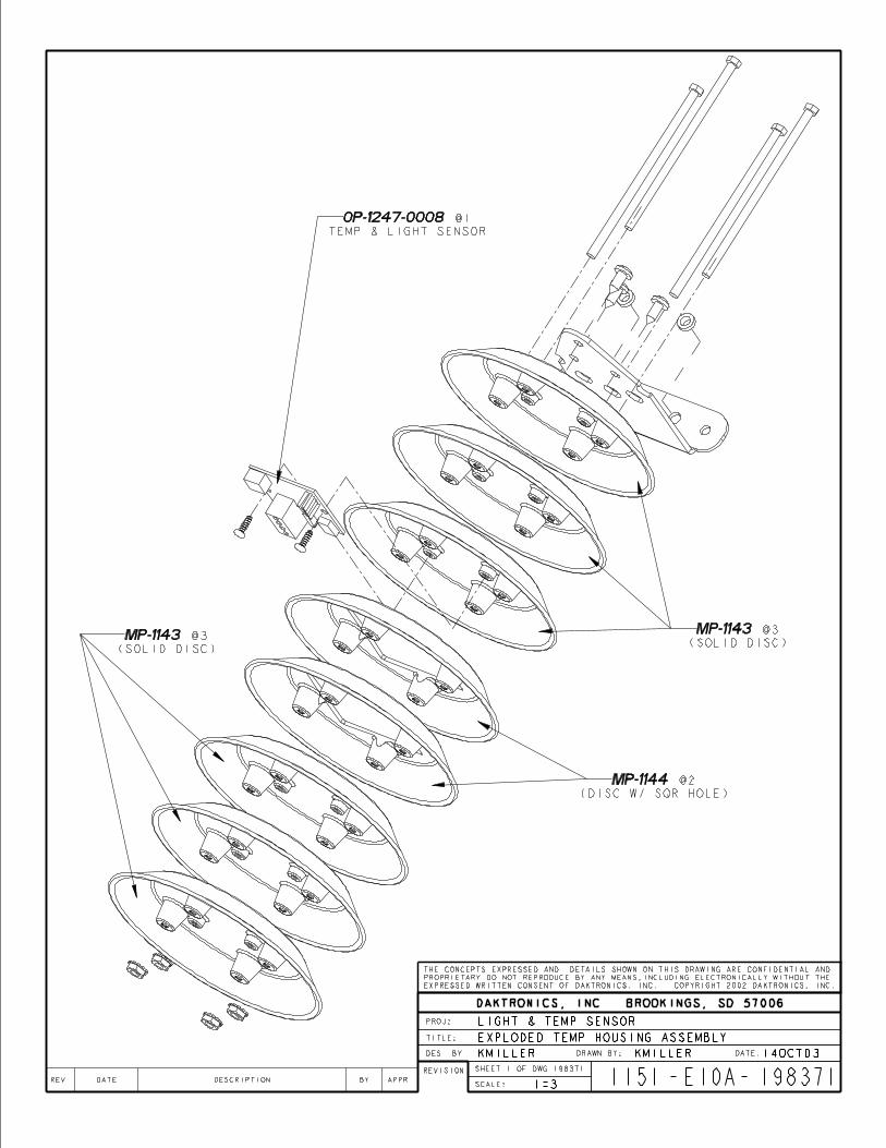
Temperature Sensor Cable Routing Schematic .............................................. Drawing A-197884 Exploded Temperature Housing Assembly...................................................... Drawing A-198371
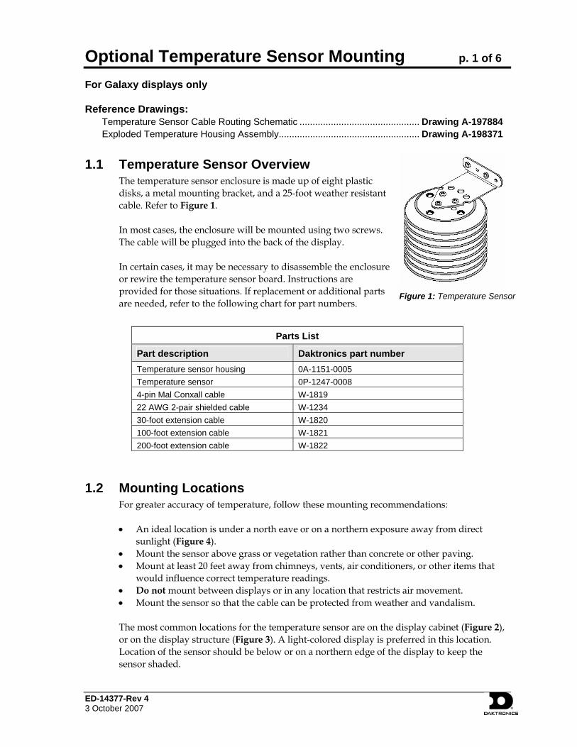
Figure 1: Temperature Sensor
1.1 Temperature Sensor Overview The temperature sensor enclosure is made up of eight plastic disks, a metal mounting bracket, and a 25-foot weather resistant cable. Refer to Figure 1. In most cases, the enclosure will be mounted using two screws. The cable will be plugged into the back of the display. In certain cases, it may be necessary to disassemble the enclosure or rewire the temperature sensor board. Instructions are provided for those situations. If replacement or additional parts are needed, refer to the following chart for part numbers.
Parts List
Part description Daktronics part number Temperature sensor housing 0A-1151-0005 Temperature sensor 0P-1247-0008 4-pin Mal Conxall cable W-1819 22 AWG 2-pair shielded cable W-1234 30-foot extension cable W-1820 100-foot extension cable W-1821 200-foot extension cable W-1822
1.2 Mounting Locations For greater accuracy of temperature, follow these mounting recommendations:
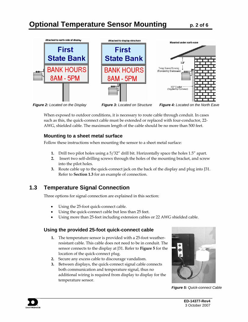
• An ideal location is under a north eave or on a northern exposure away from direct
sunlight (Figure 4). • Mount the sensor above grass or vegetation rather than concrete or other paving. • Mount at least 20 feet away from chimneys, vents, air conditioners, or other items that
would influence correct temperature readings. • Do not mount between displays or in any location that restricts air movement. • Mount the sensor so that the cable can be protected from weather and vandalism. The most common locations for the temperature sensor are on the display cabinet (Figure 2), or on the display structure (Figure 3). A light-colored display is preferred in this location. Location of the sensor should be below or on a northern edge of the display to keep the sensor shaded.
p. 2 of 6 Optional Temperature Sensor Mounting
p. 2 ED-14377-Rev4 3 October 2007
Figure 2: Located on the Display Figure 3: Located on Structure Figure 4: Located on the North Eave
When exposed to outdoor conditions, it is necessary to route cable through conduit. In cases such as this, the quick-connect cable must be extended or replaced with four-conductor, 22-AWG, shielded cable. The maximum length of the cable should be no more than 500 feet.
Mounting to a sheet metal surface Follow these instructions when mounting the sensor to a sheet metal surface:
1. Drill two pilot holes using a 5/32” drill bit. Horizontally space the holes 1.5” apart. 2. Insert two self-drilling screws through the holes of the mounting bracket, and screw
into the pilot holes. 3. Route cable up to the quick-connect jack on the back of the display and plug into J31.
Refer to Section 1.3 for an example of connection.
1.3 Temperature Signal Connection Three options for signal connection are explained in this section:
• Using the 25-foot quick-connect cable. • Using the quick-connect cable but less than 25 feet. • Using more than 25-feet including extension cables or 22 AWG shielded cable.
Using the provided 25-foot quick-connect cable
Figure 5: Quick-connect Cable
1. The temperature sensor is provided with a 25-foot weather-resistant cable. This cable does not need to be in conduit. The sensor connects to the display at J31. Refer to Figure 5 for the location of the quick-connect plug.
2. Secure any excess cable to discourage vandalism. 3. Between displays, the quick-connect signal cable connects
both communication and temperature signal, thus no additional wiring is required from display to display for the temperature sensor.
p. 3 of 6 Optional Temperature Sensor Mounting
ED-14377-Rev 4 3 October 2007
Using the quick-connect cable and less than the 25-foot cable
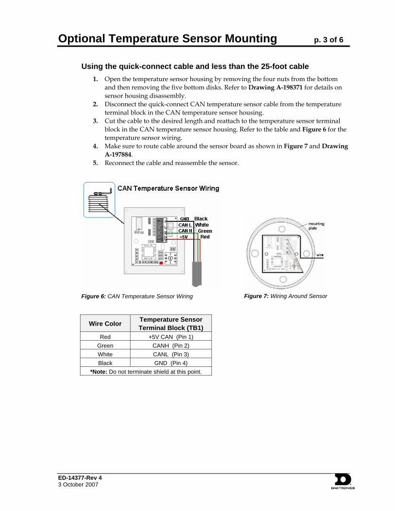
1. Open the temperature sensor housing by removing the four nuts from the bottom and then removing the five bottom disks. Refer to Drawing A-198371 for details on sensor housing disassembly.
2. Disconnect the quick-connect CAN temperature sensor cable from the temperature terminal block in the CAN temperature sensor housing.
3. Cut the cable to the desired length and reattach to the temperature sensor terminal block in the CAN temperature sensor housing. Refer to the table and Figure 6 for the temperature sensor wiring.
4. Make sure to route cable around the sensor board as shown in Figure 7 and Drawing A-197884.
5. Reconnect the cable and reassemble the sensor.
Figure 6: CAN Temperature Sensor Wiring
Figure 7: Wiring Around Sensor
Wire Color Temperature Sensor Terminal Block (TB1)
Red +5V CAN (Pin 1) Green CANH (Pin 2) White CANL (Pin 3) Black GND (Pin 4)
*Note: Do not terminate shield at this point.
p. 4 of 6 Optional Temperature Sensor Mounting
p. 4 ED-14377-Rev4 3 October 2007
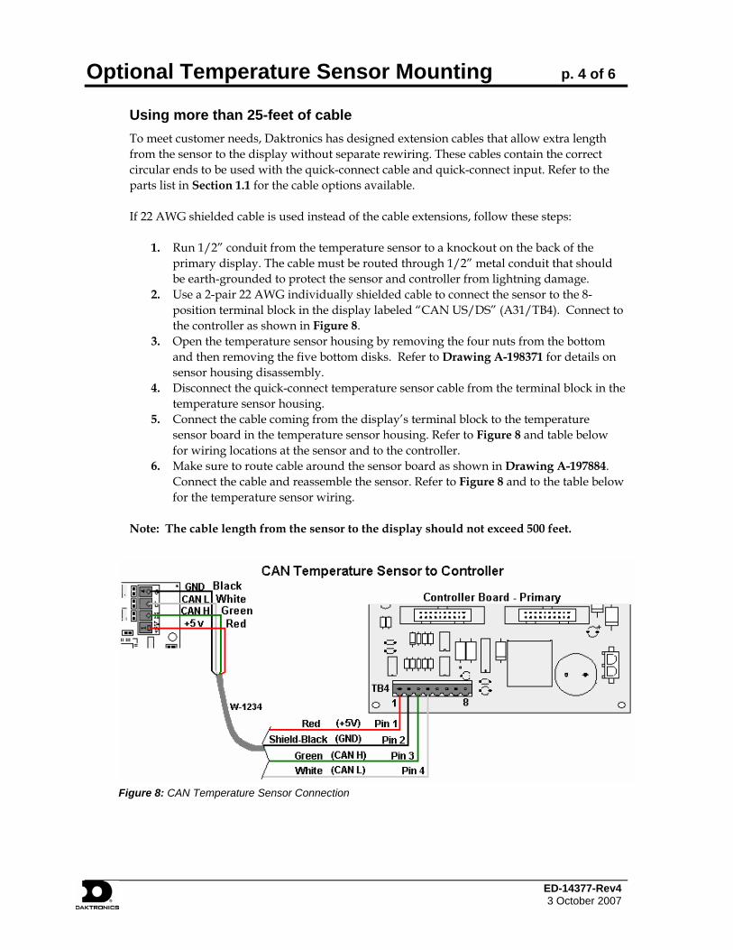
Using more than 25-feet of cable To meet customer needs, Daktronics has designed extension cables that allow extra length from the sensor to the display without separate rewiring. These cables contain the correct circular ends to be used with the quick-connect cable and quick-connect input. Refer to the parts list in Section 1.1 for the cable options available.
If 22 AWG shielded cable is used instead of the cable extensions, follow these steps:
1. Run 1/2” conduit from the temperature sensor to a knockout on the back of the
primary display. The cable must be routed through 1/2” metal conduit that should be earth-grounded to protect the sensor and controller from lightning damage.
2. Use a 2-pair 22 AWG individually shielded cable to connect the sensor to the 8-position terminal block in the display labeled “CAN US/DS” (A31/TB4). Connect to the controller as shown in Figure 8.
3. Open the temperature sensor housing by removing the four nuts from the bottom and then removing the five bottom disks. Refer to Drawing A-198371 for details on sensor housing disassembly.
4. Disconnect the quick-connect temperature sensor cable from the terminal block in the temperature sensor housing.
5. Connect the cable coming from the display’s terminal block to the temperature sensor board in the temperature sensor housing. Refer to Figure 8 and table below for wiring locations at the sensor and to the controller.
6. Make sure to route cable around the sensor board as shown in Drawing A-197884. Connect the cable and reassemble the sensor. Refer to Figure 8 and to the table below for the temperature sensor wiring.
Note: The cable length from the sensor to the display should not exceed 500 feet.
Figure 8: CAN Temperature Sensor Connection
p. 5 of 6 Optional Temperature Sensor Mounting
ED-14377-Rev 4 3 October 2007
CAN Temperature Sensor (TB1)
Field Cabling
Primary - Controller Board
CAN US (A31-TB4) Pin 1 (+5V CAN) Red Pin 1 (+5V CAN)
Pin 2 (CAN H) Green Pin 3 (CAN H)
Pin 3 (CAN L) White Pin 4 (CAN L)
Pin 4 (GND CAN) Black Pin 2 (GND CAN)
Shield Pin 2 (Shield)
1.4 Temperature Interconnection Between Displays If the display uses the quick-connect interconnect cable, this connection is already complete. If the interconnect cable was not used, a 4-conductor shielded cable is needed to terminate the temperature sensor from side one to side two. One end terminates at the “CAN US/DS” 8-position terminal block (A31-TB4) on the Primary display. The other end terminates at the “CAN US/DS” 8-position terminal block (A31-TB4) at the second Primary display. Refer to Figure 9 and the table for correct interconnect locations.
Figure 9: CAN Controller Interconnect
Primary - CAN DS (A31-TB4)
Field Cabling
Secondary - CAN US (A31-TB4)
Pin 7 (CAN H) Green Pin 3 (CAN H)
Pin 8 (CAN L) White Pin 4 (CAN L)
Pin 6 (GND CAN) Black Pin 2 (GND CAN)
Pin 5 (Relay) Red Pin 1(CAN +5V)
Shield
p. 6 of 6 Optional Temperature Sensor Mounting
p. 6 ED-14377-Rev4 3 October 2007
1.5 Sensor Board Replacement If a problem occurs with the temperature sensor board or the wiring to the sensor, the board can be accessed in the following method:
1. Open the temperature sensor housing by removing the four nuts from the bottom, and removing the five bottom disks. Refer to Figure 10 or Drawing A-198371 for details on sensor housing disassembly.
2. Label the wires connected to the temperature sensor board and then disconnect the cable from the temperature sensor terminal block in the temperature sensor housing.
3. Remove the two screws holding the board to the plastic disk. Install the new board, and replace the two screws.
4. Reconnect the cable to the temperature sensor board, making sure all the wire make a good electrical connection.
5. Make sure to route cable around the sensor board as shown in Drawing A-197884, and reassemble the sensor enclosure.
Figure 10: Temperature Sensor Housing Disassembled