19
Department of Mechanical Engineering ME 322 – Mechanical Engineering Thermodynamics Lecture 26 Use of Regeneration in Vapor Power Cycles
| Date post: | 14-Mar-2023 |
| Category: |
Documents |
| Upload: | khangminh22 |
| View: | 0 times |
| Download: | 0 times |
Department of Mechanical Engineering
ME 322 – Mechanical Engineering
Thermodynamics
Lecture 26
Use of Regeneration in Vapor Power Cycles
What is Regeneration?
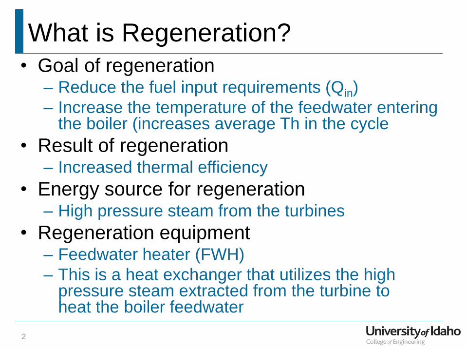
• Goal of regeneration – Reduce the fuel input requirements (Qin)
– Increase the temperature of the feedwater entering the boiler (increases average Th in the cycle
• Result of regeneration – Increased thermal efficiency
• Energy source for regeneration – High pressure steam from the turbines
• Regeneration equipment – Feedwater heater (FWH)
– This is a heat exchanger that utilizes the high pressure steam extracted from the turbine to heat the boiler feedwater
2
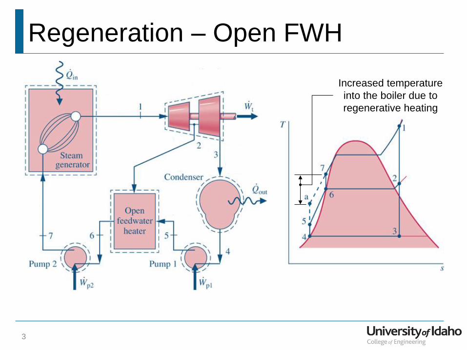
Regeneration – Open FWH
3
Increased temperature
into the boiler due to
regenerative heating
Keeping Track of Mass Flow Splits
4
1 1y
2y
3y
4y
5y6y7y
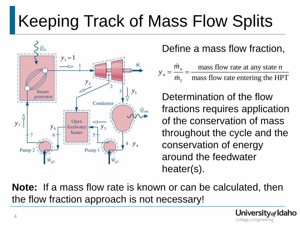
Define a mass flow fraction,
1
mass flow rate at any state
mass flow rate entering the HPT
n
n
m ny
m
Determination of the flow
fractions requires application
of the conservation of mass
throughout the cycle and the
conservation of energy
around the feedwater
heater(s).
Note: If a mass flow rate is known or can be calculated, then
the flow fraction approach is not necessary!
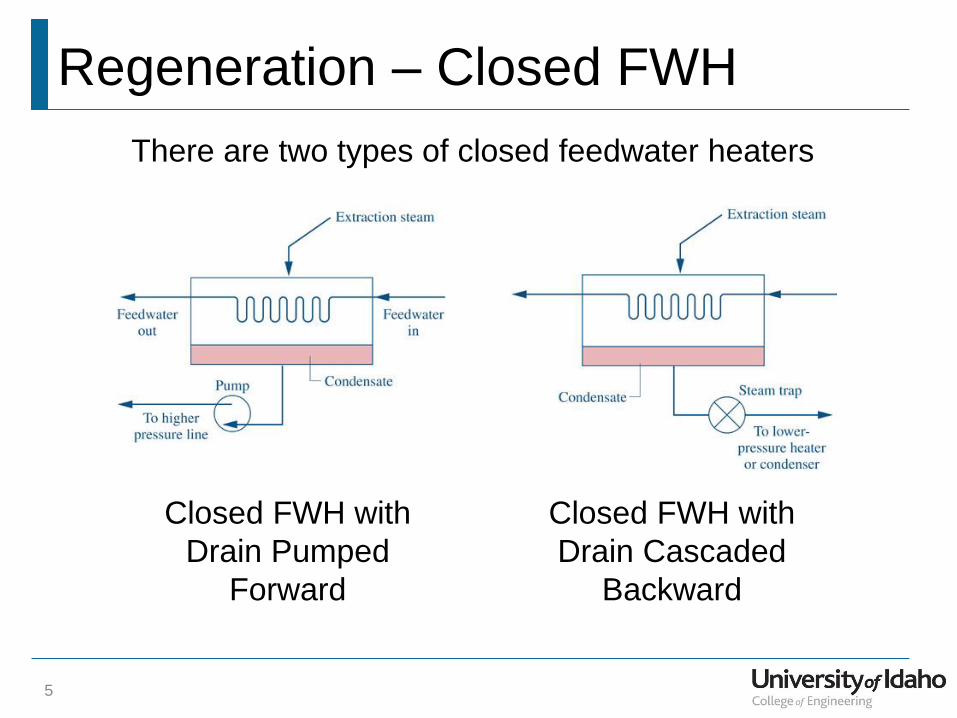
Regeneration – Closed FWH
5
There are two types of closed feedwater heaters
Closed FWH with
Drain Pumped
Forward
Closed FWH with
Drain Cascaded
Backward
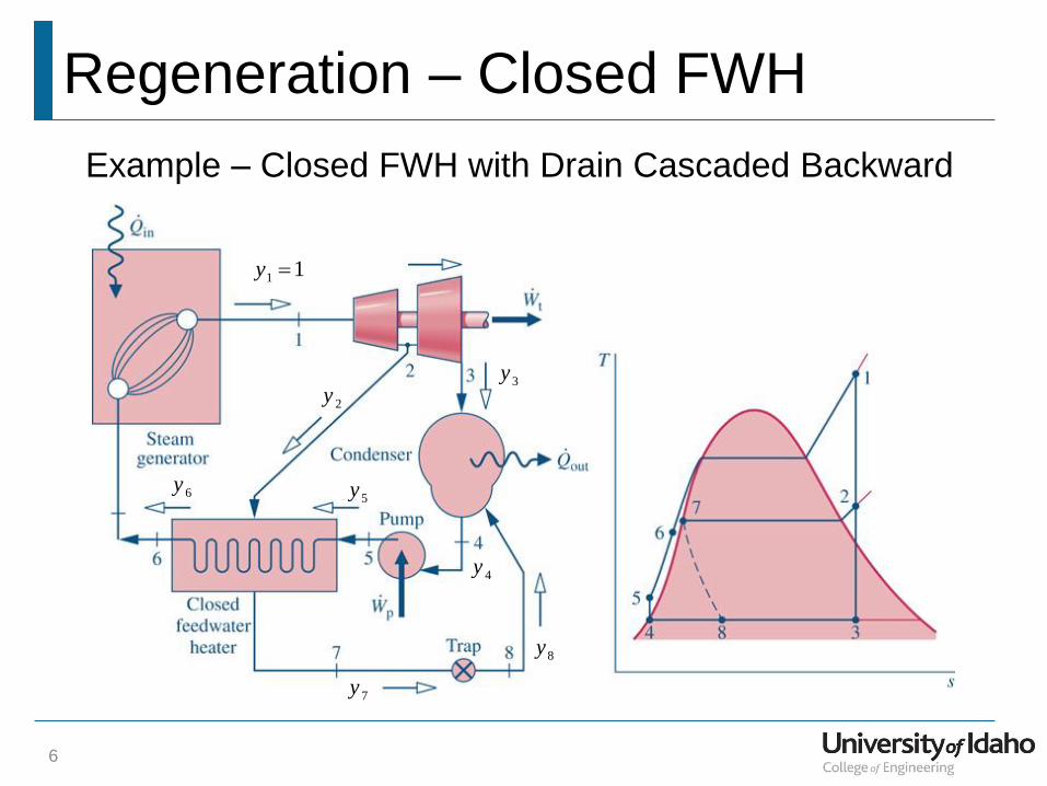
Regeneration – Closed FWH
6
Example – Closed FWH with Drain Cascaded Backward
1 1y
2y3y
4y
5y6y
7y
8y
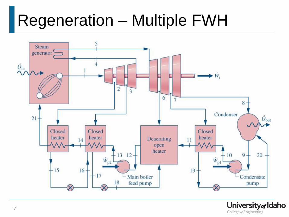
Regeneration – Multiple FWH
7
Regeneration Example
8
Given: A Rankine cycle is operating with one open
feedwater heater. Steam enters the high pressure turbine at
1500 psia, 900°F. The steam expands through the high
pressure turbine to 100 psia where some of the steam is
extracted and diverted to an open feedwater heater. The
remaining steam expands through the low pressure turbine
to the condenser pressure of 1 psia. Saturated liquid exits
the feedwater heater and the condenser.
Find:
(a) the boiler heat transfer per lbm of steam entering the
high pressure turbine
(b) the thermal efficiency of the cycle
(c) the heat rate of the cycle
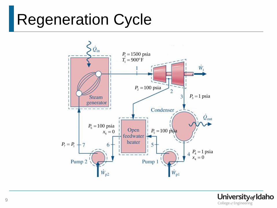
Regeneration Cycle
9
1
1
1500 psia900 F
PT
2 100 psiaP
3 1 psiaP
4
4
1 psia0
Px
5 100 psiaP 6
6
100 psia0
Px
7 1P P
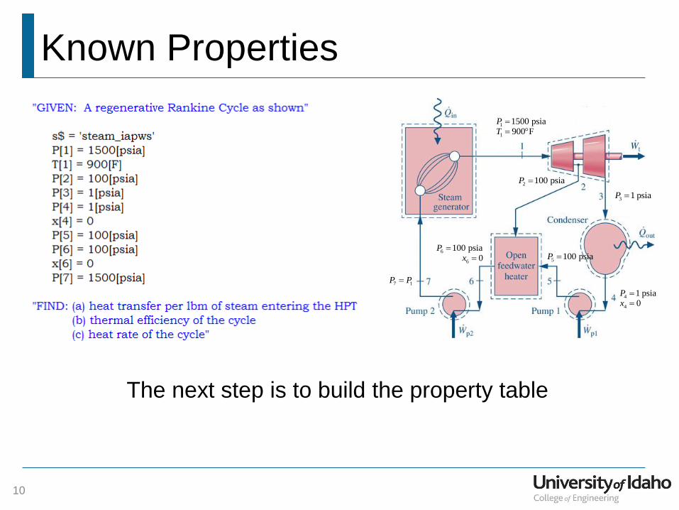
Known Properties
10
1
1
1500 psia900 F
PT
2 100 psiaP
3 1 psiaP
4
4
1 psia0
Px
5 100 psiaP 6
6
100 psia0
Px
7 1P P
The next step is to build the property table
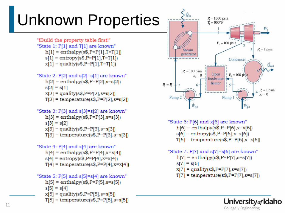
Unknown Properties
11
1
1
1500 psia900 F
PT
2 100 psiaP
3 1 psiaP
4
4
1 psia0
Px
5 100 psiaP 6
6
100 psia0
Px
7 1P P
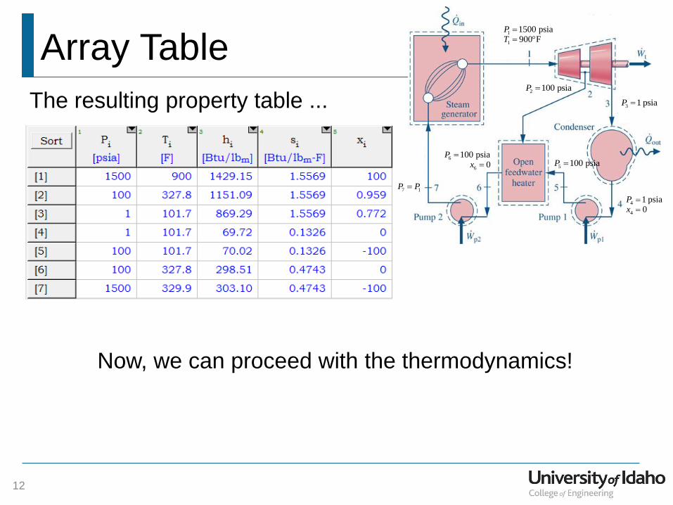
Array Table
12
1
1
1500 psia900 F
PT
2 100 psiaP
3 1 psiaP
4
4
1 psia0
Px
5 100 psiaP 6
6
100 psia0
Px
7 1P P
The resulting property table ...
Now, we can proceed with the thermodynamics!
Boiler Modeling
13
1
1
1500 psia900 F
PT
2 100 psiaP
3 1 psiaP
4
4
1 psia0
Px
5 100 psiaP 6
6
100 psia0
Px
7 1P P
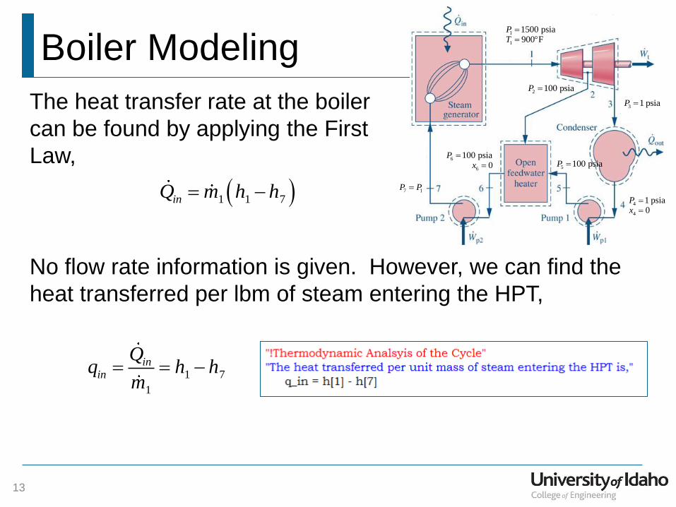
The heat transfer rate at the boiler
can be found by applying the First
Law,
1 1 7inQ m h h
No flow rate information is given. However, we can find the
heat transferred per lbm of steam entering the HPT,
1 7
1
inin
Qq h h
m
Turbine Modeling
14
1
1
1500 psia900 F
PT
2 100 psiaP
3 1 psiaP
4
4
1 psia0
Px
5 100 psiaP 6
6
100 psia0
Px
7 1P P
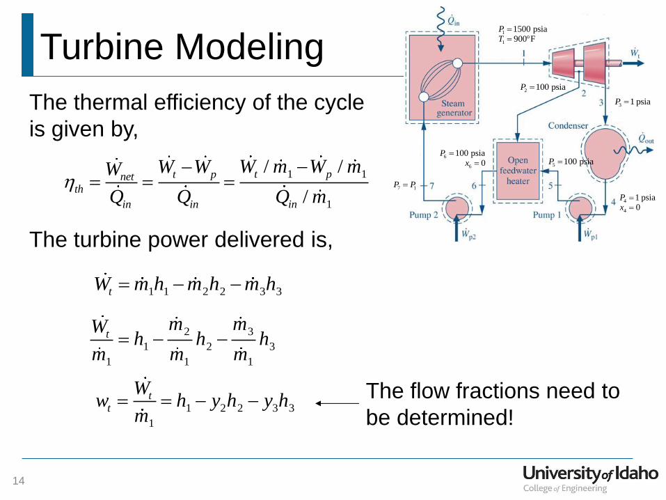
The thermal efficiency of the cycle
is given by,
t pnetth
in in
W WW
Q Q
The turbine power delivered is,
1 1 2 2 3 3tW m h m h m h
2 3
1 2 3
1 1 1
tm mW
h h hm m m
1 2 2 3 3
1
tt
Ww h y h y h
m The flow fractions need to
be determined!
1 1
1
/ /
/
t p
in
W m W m
Q m
Pump Modeling
15
1
1
1500 psia900 F
PT
2 100 psiaP
3 1 psiaP
4
4
1 psia0
Px
5 100 psiaP 6
6
100 psia0
Px
7 1P P
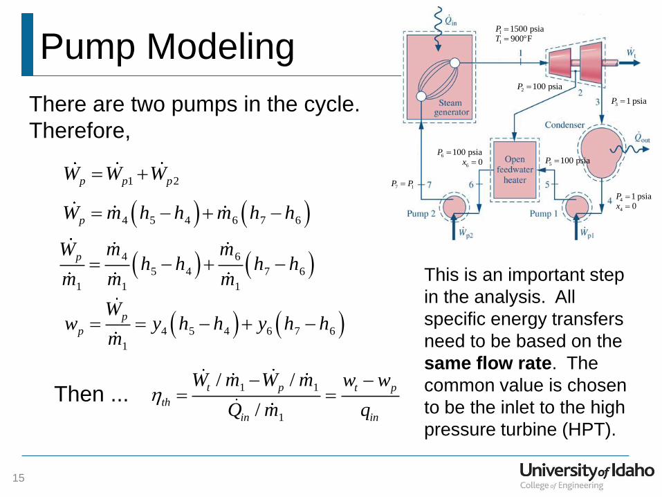
There are two pumps in the cycle.
Therefore,
1 2p p pW W W
4 5 4 6 7 6pW m h h m h h
4 6
5 4 7 6
1 1 1
pm mW
h h h hm m m
4 5 4 6 7 6
1
p
p
Ww y h h y h h
m
1 1
1
/ /
/
t p t p
th
in in
W m W m w w
Q m q
Then ...
This is an important step
in the analysis. All
specific energy transfers
need to be based on the
same flow rate. The
common value is chosen
to be the inlet to the high
pressure turbine (HPT).
Mass Conservation
16
1
1
1500 psia900 F
PT
2 100 psiaP
3 1 psiaP
4
4
1 psia0
Px
5 100 psiaP 6
6
100 psia0
Px
7 1P P
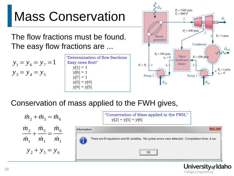
The flow fractions must be found.
The easy flow fractions are ...
2 5 6m m m
2 5 6
1 1 1
m m m
m m m
2 5 6y y y
1 6 7 1y y y
3 4 5y y y
Conservation of mass applied to the FWH gives,
Closing the System
17
1
1
1500 psia900 F
PT
2 100 psiaP
3 1 psiaP
4
4
1 psia0
Px
5 100 psiaP 6
6
100 psia0
Px
7 1P P
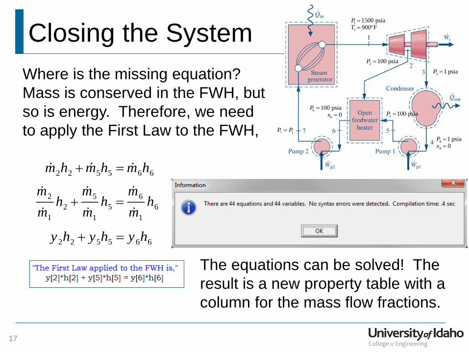
Where is the missing equation?
Mass is conserved in the FWH, but
so is energy. Therefore, we need
to apply the First Law to the FWH,
2 2 5 5 6 6m h m h m h
2 5 6
2 5 6
1 1 1
m m mh h h
m m m
2 2 5 5 6 6y h y h y h
The equations can be solved! The
result is a new property table with a
column for the mass flow fractions.
Augmented Array
18
1
1
1500 psia900 F
PT
2 100 psiaP
3 1 psiaP
4
4
1 psia0
Px
5 100 psiaP 6
6
100 psia0
Px
7 1P P
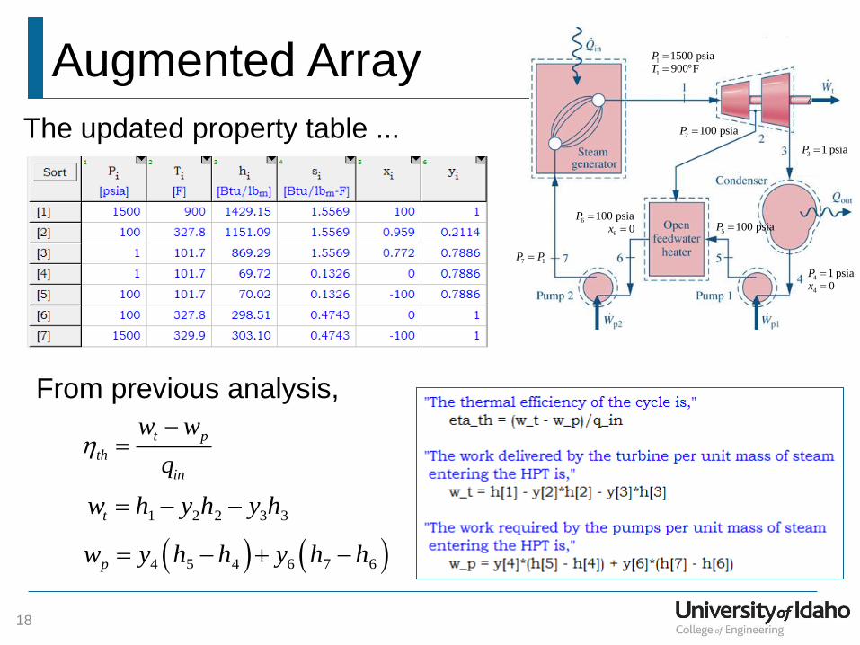
The updated property table ...
From previous analysis,
t p
th
in
w w
q
1 2 2 3 3tw h y h y h
4 5 4 6 7 6pw y h h y h h
Cycle Performance Parameters
19
1
1
1500 psia900 F
PT
2 100 psiaP
3 1 psiaP
4
4
1 psia0
Px
5 100 psiaP 6
6
100 psia0
Px
7 1P P
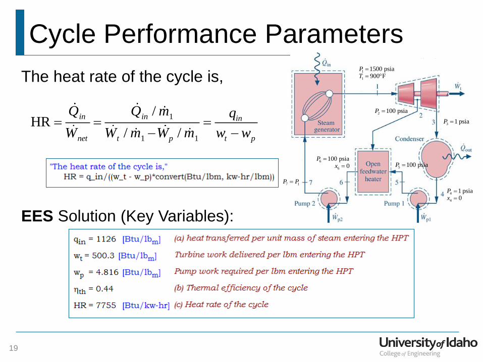
The heat rate of the cycle is,
1
1 1
/HR
/ /
in in in
net t p t p
Q Q m q
W W m W m w w
EES Solution (Key Variables):


