31
Electric Circuits (Fall 2015) Pingqiang Zhou Lecture 4 - Methods of Circuit Analysis 10/8/2015 Reading: Chapter 3 Lecture 4 1
| Date post: | 07-May-2023 |
| Category: |
Documents |
| Upload: | khangminh22 |
| View: | 0 times |
| Download: | 0 times |
Electric Circuits (Fall 2015) Pingqiang Zhou
Lecture 4
- Methods of Circuit Analysis
10/8/2015
Reading: Chapter 3
Lecture 4 1

Electric Circuits (Fall 2015) Pingqiang Zhou
Outline
• With Ohm’s and Kirchhoff’s law established, they may
now be applied to circuit analysis.
• Two techniques will be presented in this lecture:
Nodal analysis, which is based on KCL
Mesh analysis, which is based on KVL
• Any linear circuit can be analyzed using these two
techniques.
• The analysis will result in a set of simultaneous equations
which may be solved by Cramer’s rule or computationally
(using MATLAB for example)
Computational circuit analysis using PSpice will also be
introduced here.
Lecture 4 2
Electric Circuits (Fall 2015) Pingqiang Zhou
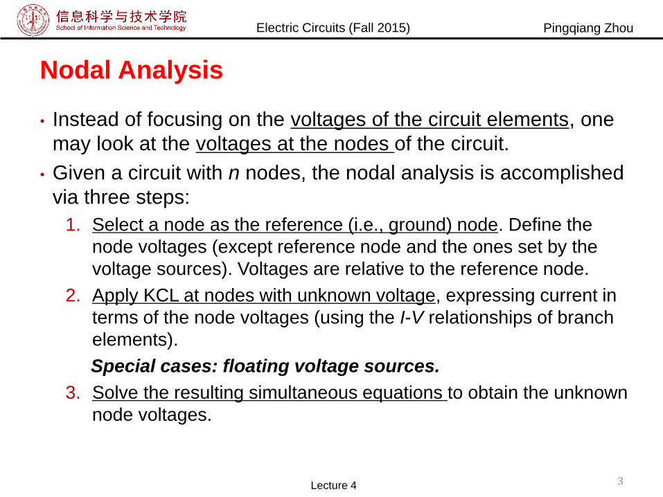
Nodal Analysis
• Instead of focusing on the voltages of the circuit elements, one
may look at the voltages at the nodes of the circuit.
• Given a circuit with n nodes, the nodal analysis is accomplished
via three steps:
1. Select a node as the reference (i.e., ground) node. Define the
node voltages (except reference node and the ones set by the
voltage sources). Voltages are relative to the reference node.
2. Apply KCL at nodes with unknown voltage, expressing current in
terms of the node voltages (using the I-V relationships of branch
elements).
Special cases: floating voltage sources.
3. Solve the resulting simultaneous equations to obtain the unknown
node voltages.
Lecture 4 3
Electric Circuits (Fall 2015) Pingqiang Zhou
Apply Nodal Analysis
• Let’s apply nodal analysis to this circuit to see
how it works.
• This circuit has a node that is designed as
ground. We will use that as the reference node
(node 0). The remaining two nodes are
designed 1 and 2 and assigned voltages v1
and v2.
• Now apply KCL to each node:
At node 1
At node 2
2121 iiII
322 iiI
Lecture 4 4
Three variables, but only two equations.
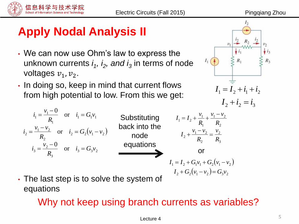
Electric Circuits (Fall 2015) Pingqiang Zhou
Apply Nodal Analysis II
• We can now use Ohm’s law to express the
unknown currents i1, i2, and i3 in terms of node
voltages 𝑣1, 𝑣2.
• In doing so, keep in mind that current flows
from high potential to low. From this we get:
• The last step is to solve the system of
equations
233
3
23
2122
2
212
111
1
11
or0
or
or0
vGiR
vi
vvGiR
vvi
vGiR
vi
Substituting
back into the
node
equations3
2
2
212
2
21
1
121
R
v
R
vvI
R
vv
R
vII
232122
2121121
vGvvGI
vvGvGII
or
Lecture 4 5
2121 iiII
322 iiI
Why not keep using branch currents as variables?
Electric Circuits (Fall 2015) Pingqiang Zhou
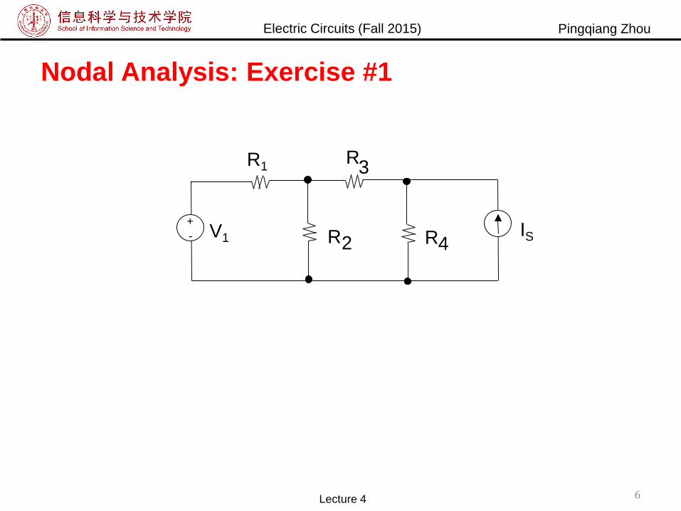
Nodal Analysis: Exercise #1
6Lecture 4
R4V1 R2
+
- IS
R3R1
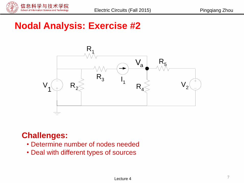
Electric Circuits (Fall 2015) Pingqiang Zhou
V2V
1R
2
R1
R4
R5
R3 I1
Va
Nodal Analysis: Exercise #2
Challenges: • Determine number of nodes needed
• Deal with different types of sources
Lecture 4 7

Electric Circuits (Fall 2015) Pingqiang Zhou
Nodal Analysis w/ “Floating Voltage Source”
8Lecture 4
A “floating” voltage source is one for which neither side is
connected to the reference node, e.g. VLL in the circuit below:
Problem: We cannot write KCL at nodes a or b because there is no
way to express the current through the voltage source in terms of Va-Vb.
Solution: Define a “supernode” – that chunk of the circuit containing
nodes a and b. Express KCL for this supernode. Incorporate voltage
source constraint into KCL equation.
R4R 2 I2
Va Vb
+-
VLL
I1
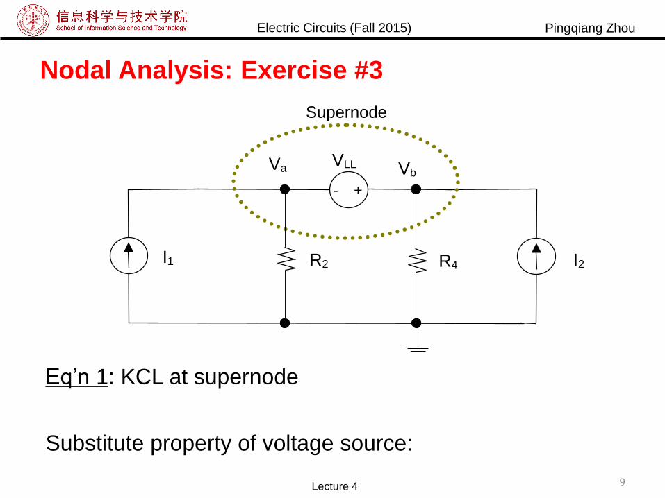
Electric Circuits (Fall 2015) Pingqiang Zhou
Nodal Analysis: Exercise #3
9Lecture 4
Eq’n 1: KCL at supernode
Substitute property of voltage source:
Supernode
R4R2 I2
Va Vb
+-
VLL
I1

Electric Circuits (Fall 2015) Pingqiang Zhou
Mesh Analysis
• Another general procedure for analyzing circuits is to use the
mesh currents as the circuit variables.
• Recall:
A loop is a closed path with no node passed more than once
A mesh is a loop that does not contain any other loop within it
• Mesh analysis uses KVL to find unknown currents.
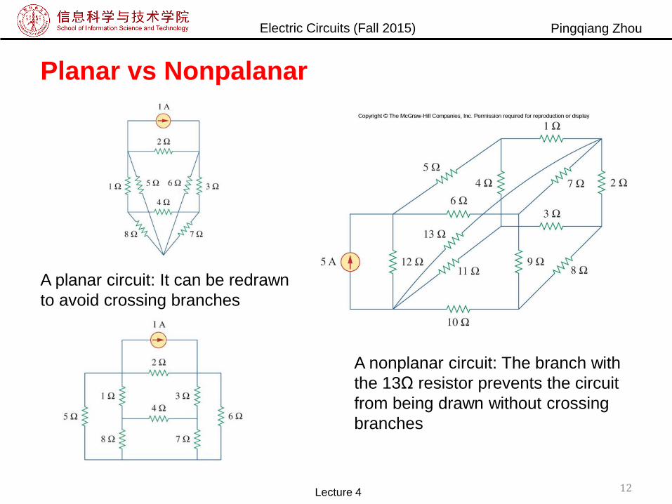
• Mesh analysis is limited in one aspect: It can only apply to
circuits that is planar.▪ A planar circuit can be drawn such that there are no crossing
branches.Lecture 4 10
Mesh = Independent loop?

Electric Circuits (Fall 2015) Pingqiang Zhou
Example
• A loop is independent if it contains at least one branch
which is not a part of any other independent loop.
• A mesh is a loop that does not contain any other loop
within it
Lecture 4 11
Electric Circuits (Fall 2015) Pingqiang Zhou
Planar vs Nonpalanar
A nonplanar circuit: The branch with
the 13Ω resistor prevents the circuit
from being drawn without crossing
branches
A planar circuit: It can be redrawn
to avoid crossing branches
Lecture 4 12

Electric Circuits (Fall 2015) Pingqiang Zhou
Mesh Analysis Steps
• Mesh analysis follows these steps:
1. Assign mesh currents i1,i2,…in to the n meshes
2. Apply KVL to each of the n mesh currents.
3. Solve the resulting n simultaneous equations to get the
mesh currents
Lecture 4 13

Electric Circuits (Fall 2015) Pingqiang Zhou
Mesh Analysis Example
• The above circuit has two paths that are meshes (abefa and bcdeb)
The outer loop (abcdefa) is a loop, but not a mesh
• First, mesh currents i1 and i2 are assigned to the two meshes.
• Applying KVL to the meshes:
223213
123222
123131
213111 00
ViRRiR
iiRViR
ViRiRR
iiRiRV
Lecture 4 14
Electric Circuits (Fall 2015) Pingqiang Zhou
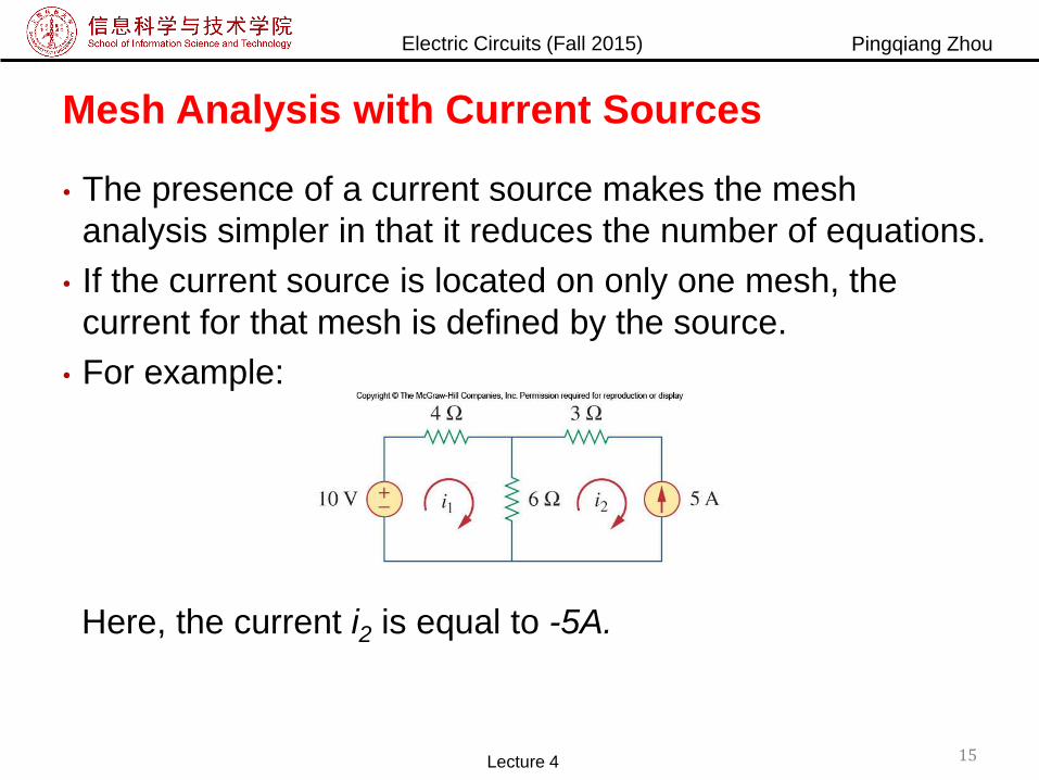
Mesh Analysis with Current Sources
• The presence of a current source makes the mesh
analysis simpler in that it reduces the number of equations.
• If the current source is located on only one mesh, the
current for that mesh is defined by the source.
• For example:
Here, the current i2 is equal to -5A.
Lecture 4 15
Electric Circuits (Fall 2015) Pingqiang Zhou
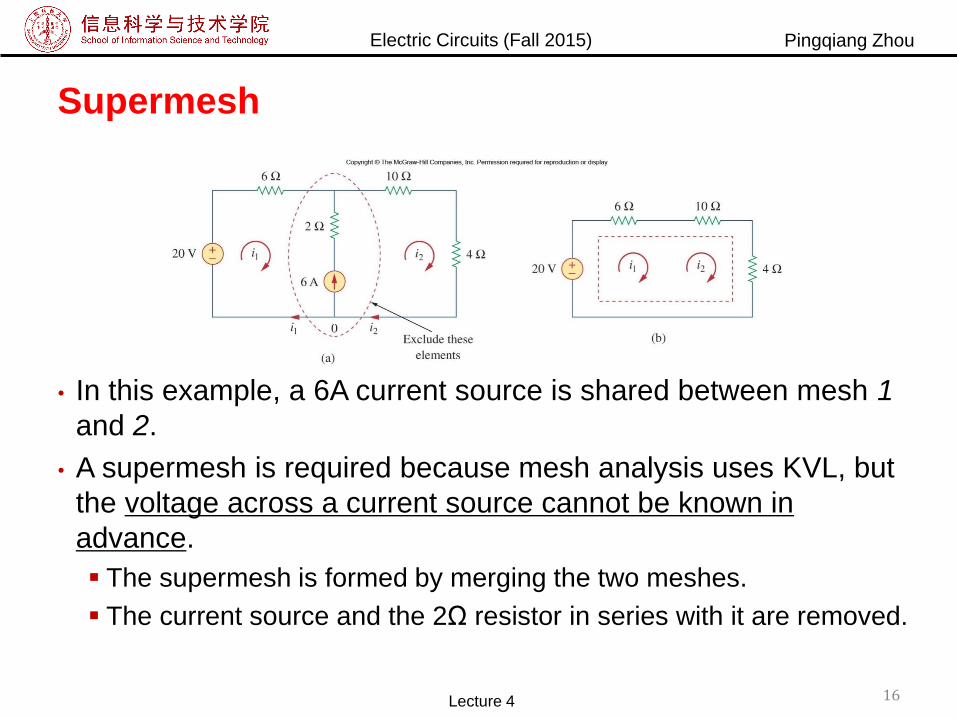
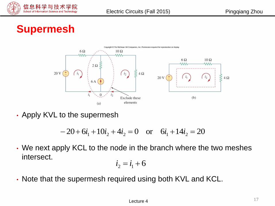
Supermesh
• In this example, a 6A current source is shared between mesh 1
and 2.
• A supermesh is required because mesh analysis uses KVL, but
the voltage across a current source cannot be known in
advance.
The supermesh is formed by merging the two meshes.
The current source and the 2Ω resistor in series with it are removed.
Lecture 4 16
Electric Circuits (Fall 2015) Pingqiang Zhou
Supermesh
• Apply KVL to the supermesh
• We next apply KCL to the node in the branch where the two meshes
intersect.
• Note that the supermesh required using both KVL and KCL.
20146or0410620 21221 iiiii
612 ii
Lecture 4 17
Electric Circuits (Fall 2015) Pingqiang Zhou
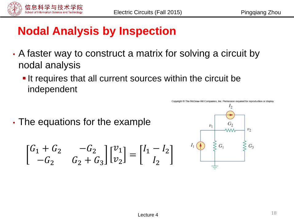
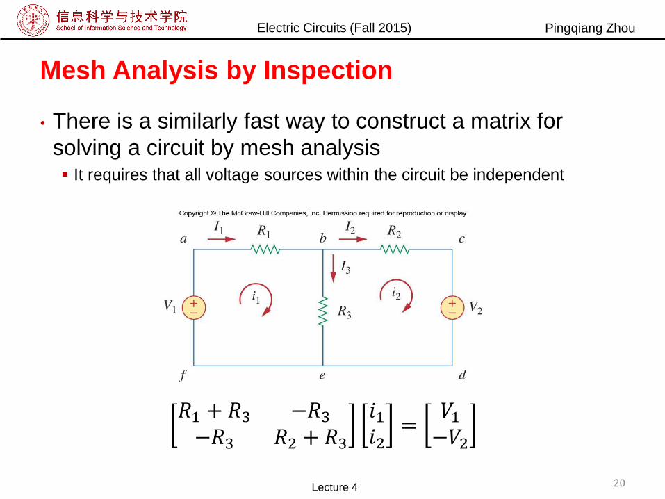
Nodal Analysis by Inspection
• A faster way to construct a matrix for solving a circuit by
nodal analysis
It requires that all current sources within the circuit be
independent
• The equations for the example
𝐺1 + 𝐺2 −𝐺2−𝐺2 𝐺2 + 𝐺3
𝑣1𝑣2
=𝐼1 − 𝐼2𝐼2
Lecture 4 18
Electric Circuits (Fall 2015) Pingqiang Zhou
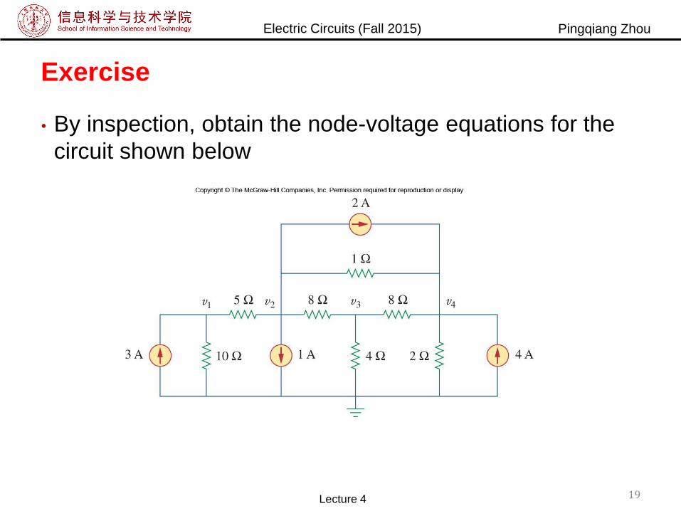
Exercise
• By inspection, obtain the node-voltage equations for the
circuit shown below
19Lecture 4
Electric Circuits (Fall 2015) Pingqiang Zhou
Mesh Analysis by Inspection
• There is a similarly fast way to construct a matrix for
solving a circuit by mesh analysis It requires that all voltage sources within the circuit be independent
𝑅1 + 𝑅3 −𝑅3−𝑅3 𝑅2 + 𝑅3
𝑖1𝑖2
=𝑉1−𝑉2
Lecture 4 20
Electric Circuits (Fall 2015) Pingqiang Zhou
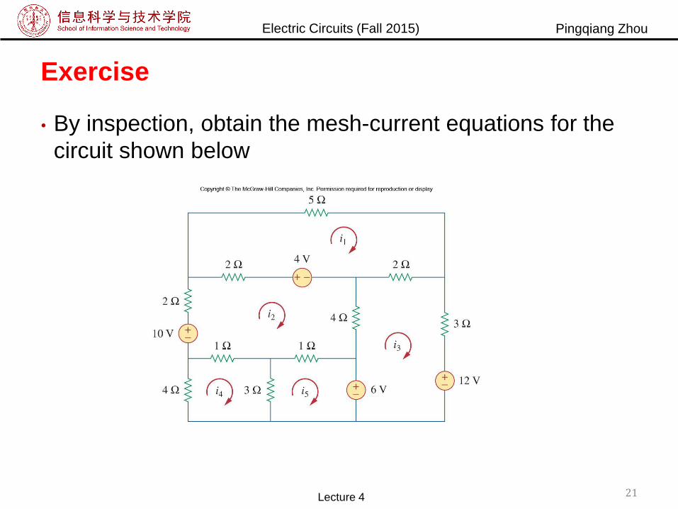
Exercise
• By inspection, obtain the mesh-current equations for the
circuit shown below
21Lecture 4
Electric Circuits (Fall 2015) Pingqiang Zhou
Nodal vs. Mesh
• In principle both the nodal analysis and mesh analysis are
useful for any given circuit.
• What then determines if one is going to be more efficient
for solving a circuit problem?
• There are two factors that dictate the best choice:
The nature of the particular network
The information required
Lecture 4 22

Electric Circuits (Fall 2015) Pingqiang Zhou
Nodal Analysis if…
• If the network contains:
Many parallel connected elements
Current sources
Supernodes
Circuits with fewer nodes than meshes
• If node voltages are what are being solved for
• Non-planar circuits can only be solved using nodal
analysis
• This format is easier to solve by computer
Easy to program
Lecture 4 23
Electric Circuits (Fall 2015) Pingqiang Zhou
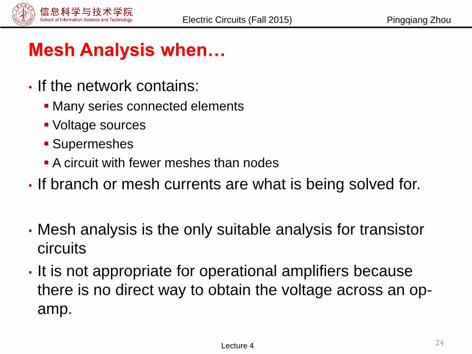
Mesh Analysis when…
• If the network contains:
Many series connected elements
Voltage sources
Supermeshes
A circuit with fewer meshes than nodes
• If branch or mesh currents are what is being solved for.
• Mesh analysis is the only suitable analysis for transistor
circuits
• It is not appropriate for operational amplifiers because
there is no direct way to obtain the voltage across an op-
amp.
Lecture 4 24
Electric Circuits (Fall 2015) Pingqiang Zhou
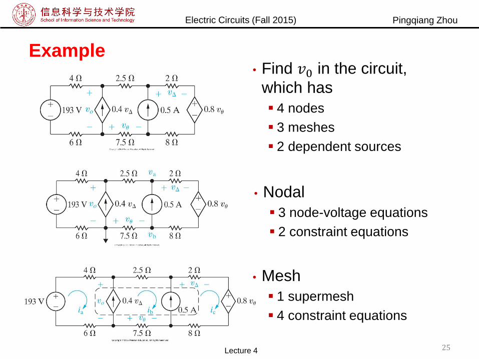
Example• Find 𝑣0 in the circuit,
which has
4 nodes
3 meshes
2 dependent sources
25
• Nodal
3 node-voltage equations
2 constraint equations
• Mesh
1 supermesh
4 constraint equations
Lecture 4

Electric Circuits (Fall 2015) Pingqiang Zhou
Circuit Analysis with PSpice
• PSpice is a common program used for circuit analysis.
• It is capable of determining all of the branch voltages and
currents if the numerical values for all circuit components
are known.
• Analysis using PSpice begins with drawing a schematic
view of the circuit.
Lecture 4 26
Electric Circuits (Fall 2015) Pingqiang Zhou
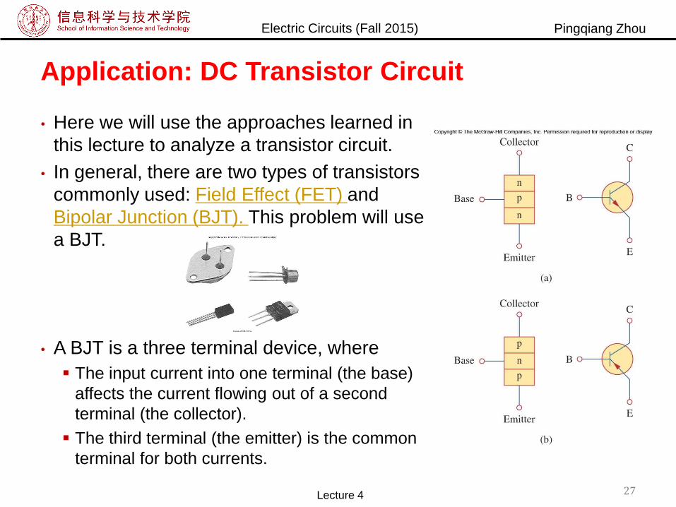
Application: DC Transistor Circuit
• Here we will use the approaches learned in
this lecture to analyze a transistor circuit.
• In general, there are two types of transistors
commonly used: Field Effect (FET) and
Bipolar Junction (BJT). This problem will use
a BJT.
• A BJT is a three terminal device, where
The input current into one terminal (the base)
affects the current flowing out of a second
terminal (the collector).
The third terminal (the emitter) is the common
terminal for both currents.
Lecture 4 27
Electric Circuits (Fall 2015) Pingqiang Zhou
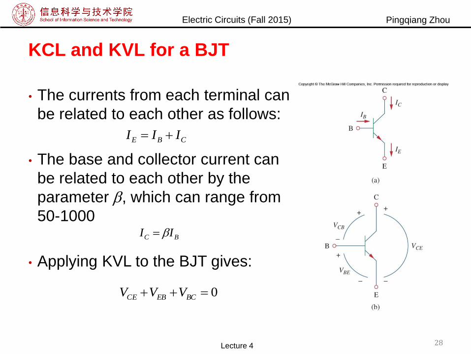
KCL and KVL for a BJT
• The currents from each terminal can
be related to each other as follows:
• The base and collector current can
be related to each other by the
parameter , which can range from
50-1000
• Applying KVL to the BJT gives:
CBE III
0 BCEBCE VVV
BC II
Lecture 4 28
Electric Circuits (Fall 2015) Pingqiang Zhou
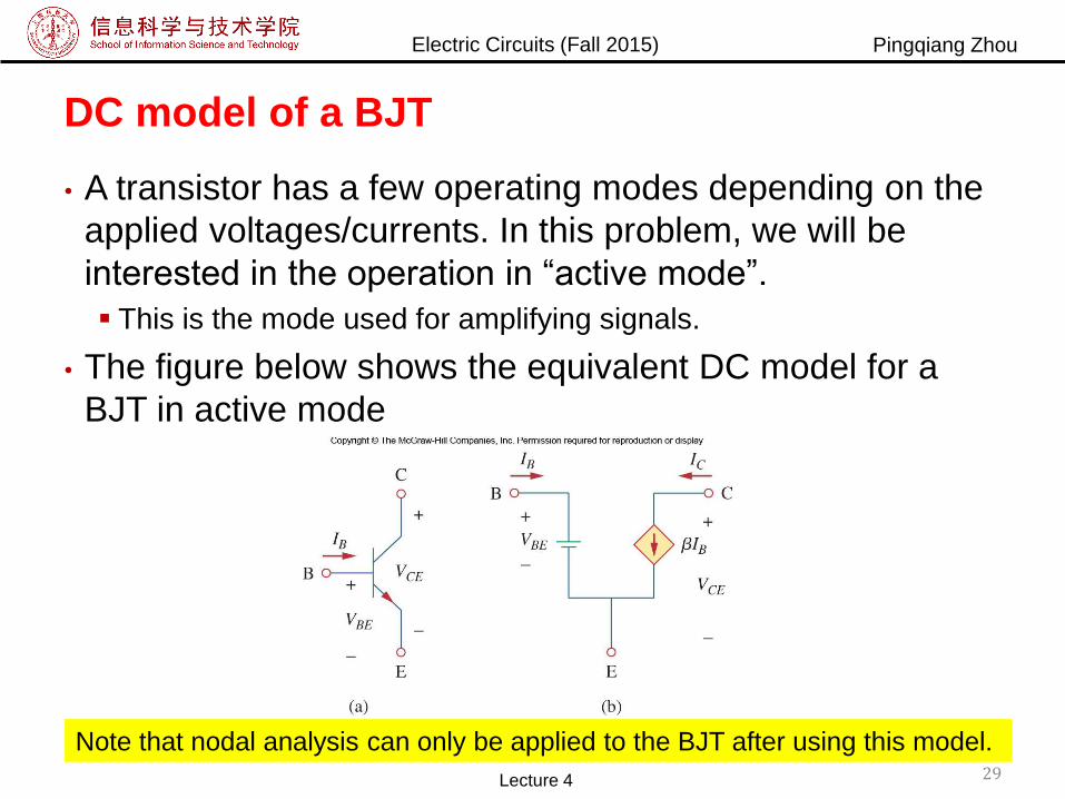
DC model of a BJT
• A transistor has a few operating modes depending on the
applied voltages/currents. In this problem, we will be
interested in the operation in “active mode”.
This is the mode used for amplifying signals.
• The figure below shows the equivalent DC model for a
BJT in active mode
Note that nodal analysis can only be applied to the BJT after using this model.
Lecture 4 29
Electric Circuits (Fall 2015) Pingqiang Zhou
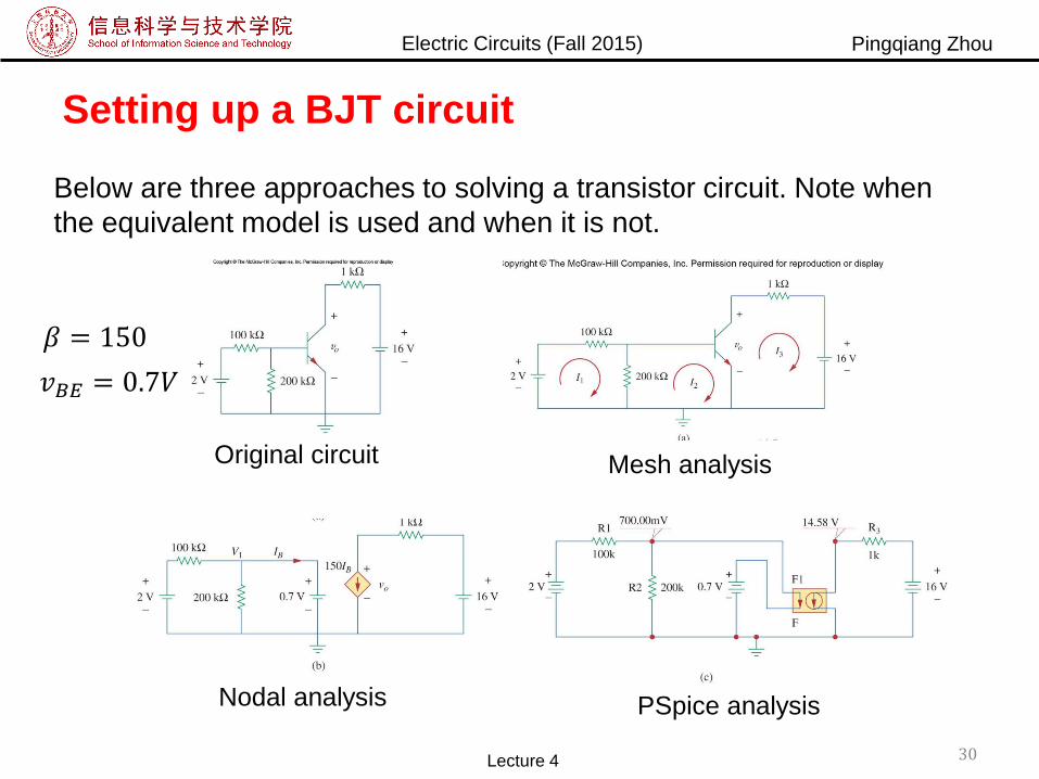
Setting up a BJT circuit
Below are three approaches to solving a transistor circuit. Note when
the equivalent model is used and when it is not.
Original circuit Mesh analysis
Nodal analysis PSpice analysis
Lecture 4 30
𝛽 = 150
𝑣𝐵𝐸 = 0.7𝑉
Electric Circuits (Fall 2015) Pingqiang Zhou
Summary
• Node Analysis Node voltage is the unknown
Solve by KCL
Special case: Floating voltage source using supernode
• Mesh Analysis: OPTIONAL Loop current is the unknown
Solve by KVL
Special case: Current source using supermesh
Lecture 4 31


