446 NAFTA-GAZ Nafta-Gaz 2021, no. 7, pp. 446–453, DOI: 10.18668/NG.2021.07.03 Mechanical aspects of wellbore stability in shales and coals Stateczność otworów w warstwach łupków oraz węgli Tadeusz Szpunar, Paweł Budak Oil and Gas Institute – National Research Institute ABSTRACT: This paper presents a simple model which can be used to calculate the following values: • critical depth for which the well integrity is preserved in a shale or coal horizon with actual shale/coal mechanical parameters, actual mud density and reservoir parameters; • minimum mud density at which stress concentration at the wellbore wall is below the allowable limit for a given rock’s mechanical parameters, formation pressure gradient, and overburden pressure gradient; • mud density required for the preservation of shale/coal integrity at the wellbore wall at any depth, assuming that the strength pa- rameters of shale or coal, formation pressure gradient, and overburden pressure gradient are constant. The appropriate equations were derived using the maximum principal strain hypothesis, which holds for brittle materials. It was also assumed that the radial pressure at the borehole wall is caused by the weight of overburden rocks. The author’s intention was to pro- vide formulas which are as simple as possible and which can be easily used in practice. The final equations were based on the solution to the Lame problem, which was adopted to represent a vertical drilling well with a circular cross-section and filled with mud whose hydrostatic pressure is assumed to oppose the pore pressure. Included are effects of silt swelling pressure, overburden pressure, mud density and the mechanical properties of the rock – including the unconfined compressive strength and Poisson ’ s ratio. In the case of shale or silty coal layers, the swelling pressure increases the volume of the clay minerals in the pores by diffusion the mud filtrate, which reduces the pore volume and increases the pore pressure, and therefore impacts the calculations. Presented model allows for derivation of the Hubert–Willis formula for fracturing pressure or fracture pressure gradient, which are commonly used in the oil industry. The calculation results are presented using data from the domestic oil industry and data from one of the Polish coal mines. Key words: well stability, shale/coal mechanical parameters, unconfined compressive strength, Poisson’s ratio, swelling pressure, overburden pressure, mud density. STRESZCZENIE: W artykule podano prosty model umożliwiający obliczenie następujących wielkości: • głębokości krytycznej, w jakiej pokład łupków lub węgla zachowa integralność przy danych parametrach mechanicznych łupku lub węgla, danej gęstości płuczki i znanych parametrach złożowych; • minimalnej gęstości płuczki, przy której koncentracja naprężeń na ścianie otworu nie przekracza granicy dopuszczalnej dla danych parametrów mechanicznych łupku lub węgla oraz gradientu ciśnienia i nadkładu; • gęstości płuczki, przy której zachowana będzie integralność ścian otworu w warstwach łupku lub węgla w każdej głębokości dla danych parametrów mechanicznych łupku, przy stałym gradiencie ciśnienia i nadkładu. Wyprowadzono odpowiednie wzory, przyjmując hipotezę wytrzymałościową maksymalnego wytężenia materiału stosowaną w przy- padku materiałów kruchych. Przyjęto również, że przy założeniu odkształceń sprężystych ciśnienie radialne na ścianie otworu jest spo- wodowane ciężarem skał nadkładu. Intencją autorów było podanie możliwie jak najprostszych wzorów, które mogłyby zostać zasto- sowane w praktyce. Wykorzystano rozwiązania tzw. problemu Lamégo, to jest rozpatrywano stan naprężeń na ścianie pionowego wy- robiska o przekroju kołowym, traktując skałę jako materiał sprężysty. We wzorach na wielkość naprężeń na ścianie wyrobiska o prze- kroju w kształcie okręgu uwzględniono wpływ ciśnienia pęcznienia, ciśnienia wywieranego przez nadkład, gęstość płuczki, jak rów- nież parametry wytrzymałościowe łupku/węgla, w tym wytrzymałość na ściskanie w jednoosiowym stanie naprężeń i współczynnik Poissona. W przypadku warstw łupków lub węgli zailonych ciśnienie pęcznienia powoduje zwiększenie objętości minerałów ilastych w porach w wyniku dyfuzji filtratu płuczki, co zmniejsza objętość porów i zwiększa ciśnienie porowe, a zatem wpływa na wyniki ob- liczeń. Przedstawiony model pozwala na wyprowadzenie z niego powszechnie stosowanego w przemyśle wzoru Huberta–Willisa, po- dającego wielkość ciśnienia szczelinowania skał na ścianie otworu oraz gradientu ciśnienia szczelinowania. Przedstawiono wyniki ob- liczeń dla danych z otworów z krajowego przemysłu naftowego oraz jednej z polskich kopalni węgla kamiennego. Słowa kluczowe: stateczność otworu, parametry mechaniczne łupka/węgla, wytrzymałość na ściskanie, współczynnik Poissona, ciśnie- nie pęcznienia, ciśnienie nadkładu, gęstość płuczki. Corresponding author: P. Budak, e-mail: [email protected]Article contributed to the Editor: 03.03.2021. Approved for publication: 02.07.2021
Transcript
446
NAFTA-GAZ
Nafta-Gaz 2021, no. 7, pp. 446–453, DOI: 10.18668/NG.2021.07.03
Mechanical aspects of wellbore stability in shales and coals
Stateczność otworów w warstwach łupków oraz węgli
Tadeusz Szpunar, Paweł Budak
Oil and Gas Institute – National Research Institute
ABSTRACT: This paper presents a simple model which can be used to calculate the following values:• critical depth for which the well integrity is preserved in a shale or coal horizon with actual shale/coal mechanical parameters, actual
mud density and reservoir parameters;• minimum mud density at which stress concentration at the wellbore wall is below the allowable limit for a given rock’s mechanical
parameters, formation pressure gradient, and overburden pressure gradient;• mud density required for the preservation of shale/coal integrity at the wellbore wall at any depth, assuming that the strength pa-
rameters of shale or coal, formation pressure gradient, and overburden pressure gradient are constant.The appropriate equations were derived using the maximum principal strain hypothesis, which holds for brittle materials. It was also assumed that the radial pressure at the borehole wall is caused by the weight of overburden rocks. The author’s intention was to pro-videformulaswhichareassimpleaspossibleandwhichcanbeeasilyusedinpractice.ThefinalequationswerebasedonthesolutiontotheLameproblem,whichwasadoptedtorepresentaverticaldrillingwellwithacircularcross-sectionandfilledwithmudwhosehydrostaticpressureisassumedtoopposetheporepressure.Includedareeffectsofsiltswellingpressure,overburdenpressure,muddensityandthemechanicalpropertiesoftherock–includingtheunconfinedcompressivestrengthandPoisson’s ratio. In the case of shaleorsiltycoallayers,theswellingpressureincreasesthevolumeoftheclaymineralsintheporesbydiffusionthemudfiltrate,whichreducestheporevolumeandincreasestheporepressure,andthereforeimpactsthecalculations.Presentedmodelallowsforderivationof the Hubert–Willis formula for fracturing pressure or fracture pressure gradient, which are commonly used in the oil industry. The calculationresultsarepresentedusingdatafromthedomesticoilindustryanddatafromoneofthePolishcoalmines.
Article contributed to the Editor: 03.03.2021. Approved for publication: 02.07.2021
artykuły
447Nafta-Gaz, nr 7/2021
artykuły
447
Introduction
Silt rocks (mainly shales) constitute 75 percent of all rocks encountered while drilling and are blamed for 90 percent of all drilling problems, such as wellbore instability, heaving shales, bit balling, loss of circulation, pipe sticking, and the like.Themajorityoftheseproblemsarebelievedtobecausedby incompatibility of the drilling mud and rock, resulting in chemical reactions at the mud–rock interface and causing clay to swell and borehole stability to decrease (Gomez and He, 2012; Wang et al., 2017). Whilst we share this opinion, we believe that at least some of the cases of wellbore instability can be explained by rock mechanics, assuming that the state of stress at the wellbore wall is as depicted in this paper. If the shale contains silt minerals, they may swell in contact with water-based mud – this decreases the pore volume and increases the pore pressure. This additional pressure increase (called swelling pressure) may be included in the calculations by adding it to pore pressure (Koteeswaran et al., 2018). The problem of mud impact on shales has been extensively dis-cussed in the literature and is well known to mud and drilling engineers – thus it will not be discussed here (Santarelli i et al., 1992; Mody and Hale, 1993; Van Oort et al., 1994; Santarelli and Carminati, 1995; Gomez and He, 2012; Lyu et al., 2015; Wang et al., 2017). The problem of borehole stability was considered here using the very fundamental principles of rock mechanics. The authors’ intention was to provide formulas which are as simple as possible and which can be easily used in practice. The presented approach yields results which seem to be reasonable. The derivation of Equations (4)–(6) uses the very fundamental principles of rock mechanics, but the authorsdidnotfindanyexamplesintheliteraturethattakeintoaccounttheinfluenceofporepressure,swellingpressure,androckmechanicalparametersonthestabilityofawellfilledwith drilling mud of a known density.
Wellbore stability in shales and coals
The equations derived in the following chapter allow the valuesspecifiedbelowtobecalculated,providedthatshale/coalstrengthproperties–suchasPoisson’sratioµandunconfinedcompressive strength Rc – as well as the average density of overburden rocks, actual mud density, and pore pressure are known. The mud compatibility, which is believed to be the mostimportantfactorinfluencingwellborestabilityinshale,is not considered in the presented model. The values which can be calculated are as follows:a) critical depth (zcrit), which is a maximum depth at which
a shale/coal of known strength properties maintains its
integrity for a known overburden pressure gradient, pore pressure gradient, and mud density;
b) minimum mud density ρmin, which is required to maintain wellbore stability in shales/coals of known strength proper-ties deposited at an actual depth z;
c) mud density ρmax, for which a shale/coal with known strength properties preserves its integrity at the wellbore wall for any depth assuming that the overburden pressure gradient and pore pressure gradient are constant.Theequationswhichdefinethevaluesmentionedina),b),
and c) were derived assuming the state of stress at the borehole wall described in detail in the section below. The equations given below were derived using the fundamental principles of rock mechanics.
Formulaswhichdefinethecriticaldepth(zcrit) and the minimum and maximum mud pressure gradient (γmmin
and γmmax
) required to maintain wellbore stability in shales/coals of known strength properties deposited at an actual depth z and an average pressure gradient of overburden rocks γs
are given below:
����� =− �
��� ���� ���
���� � � ��������� − ��
(1)
����� � ������ � �� + � � � ���
� � �� + ���
�� + � (2)
(3)
Equations (1)–(3) in SI units are as follows:
�������m� =− �
��� ��9.81 · 10���� ���
���� � � ��������� − 9.81 · 10����
(4)
����� �kgm�� � ��
2��1 − �� + 1.02 · 10�� 1 − ���
1 − �� −
−1.02 · 10� ����
1 + �
(5)
����� �kgm�� � ��
2��1 � �� + 1.02 · 10�� 1 � ���
1 � �� (6)
where:Rc–unconfinedcompressivestrengthofrock (Rc <0)[MPa],μ –Poisson’sratio,dimensionless,ρs – average density of overburden rocks [kg/m3],ρm – mud density [kg/m3],ρmmin
– minimum mud density required to maintain wellbore stability [kg/m3],
NAFTA-GAZ
448 Nafta-Gaz, nr 7/2021
NAFTA-GAZ
448
ρmmax – maximum mud density required to maintain wellbore stability at any depth for a given rock’s param-eters [kg/m3],
z –depth[m].If a well stays empty (no mud inside, ρm =0)andtheinflu-
ence of pore pressure on wellbore stability is omitted (α = 0, solid rock with no porosity), then Equation (4) yields the depth which the well will tolerate without being cased. Equation (4) is very similar to the formula used for calculation of the al-lowable depth which the mining shaft will tolerate without being cased. One should note that because of assumed sign convention Rc < 0 in Equations (4) and (5).
Derivation of basic equations using the fundamental principles of rock mechanics
State of stress at borehole wall in shaleBefore a well is drilled, the rock mass is in a certain three-
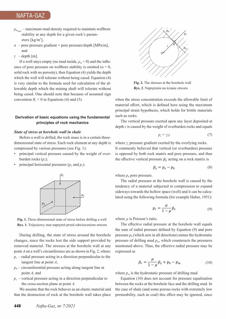
dimensional state of stress. Each rock element at any depth is compressed by various pressures (see Fig. 1):• principal vertical pressure caused by the weight of over-
burden rocks (pz);• principal horizontal pressures (p2 and p3).
when the stress concentration exceeds the allowable limit of materialeffort,whichisdefinedhereusingthemaximumprincipal strain hypothesis, which holds for brittle materials such as rocks.
The vertical pressure exerted upon any layer deposited at depth z is caused by the weight of overburden rocks and equals
pz = γsz (7)
where γs pressure gradient exerted by the overlying rocks.It commonly believed that vertical (or overburden) pressure is opposed by both rock matrix and pore pressure, and thus theeffectiveverticalpressure�̅� acting on a rock matrix is
�̅� � �� � �� (8)
where p0 pore pressure.The radial pressure at the borehole wall is caused by the
tendencyofamaterialsubjectedtocompressiontoexpandsideways towards the hollow space (well) and it can be calcu-lated using the following formula (for example Huber, 1951):
�� =�
� � � �̅� (9)
where µisPoisson’sratio.Theeffectiveradialpressureattheboreholewallequals
thesumofradialpressuredefinedbyEquation(9)andporepressure p0 (which acts in all directions) minus the hydrostatic pressure of drilling mud pm, which counteracts the pressures mentionedabove.Thus,theeffectiveradialpressuremaybeexpressed as
�̅� =�
� � � �̅� � �� � �� (10)
where pm is the hydrostatic pressure of drilling mud.Equation (10) does not account for pressure equalisation
between the rocks at the borehole face and the drilling mud. In the case of shale (and some porous rocks with extremely low permeability,suchascoal)thiseffectmaybeignored,since
Fig. 1. Three-dimensional state of stress before drilling a wellRys. 1.Trójosiowystannaprężeńprzedodwierceniemotworu
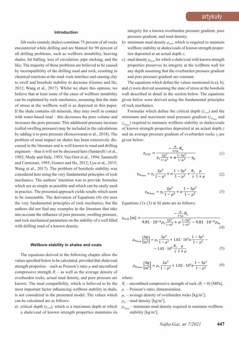
During drilling, the state of stress around the borehole changes, since the rocks lost the side support provided by removed material. The stresses at the borehole wall at any point A on a well’s circumference are as shown in Fig. 2, where:pr – radial pressure acting in a direction perpendicular to the
tangent line at point A,pθ – circumferential pressure acting along tangent line at
point A, andpz – vertical pressure acting in a direction perpendicular to
the cross-section plane at point A.We assume that the rock behaves as an elastic material and
that the destruction of rock at the borehole wall takes place
Fig. 2. The stresses at the borehole wallRys. 2.Naprężenianaścianieotworu
artykuły
449Nafta-Gaz, nr 7/2021
artykuły
449
shale has a somewhat porous structure and zero permeability, whichdisablestheflowofthemudfiltrateandequalizationofpressures. Thus, Equation (10) holds only for shales and other extremely low-permeability rocks such as coal.
Knowing the pressure (stress) values at the borehole wall, onecancalculatethematerialeffortusingthemaximumprin-cipal strain hypothesis and can tell whether the stress concen-tration exceeds the allowable limit.
Derivation of Equations (4), (5), and (6)
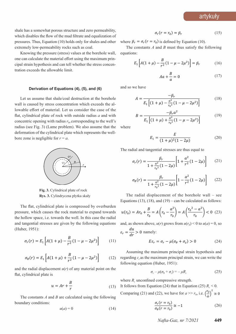
Let us assume that shale/coal destruction at the borehole wall is caused by stress concentration which exceeds the al-lowableeffortofmaterial.Letusconsiderthecaseoftheflat,cylindricalplateofrockwithoutsideradiusa and with concentric opening with radius r0, corresponding to the well’s radius (see Fig. 3) (Lame problem). We also assume that the deformation of the cylindrical plate which represents the well-bore zone is negligible for r = a.
���� � ��� � �̅� (15)
where �̅� � ���� � ��� isdefinedbyEquation(10).The constants A and B must thus satisfy the following
equations:
�� ���� � �� − ��� �� − � − ����� � �̅�
(16)
�� � �� = 0 (17)
and so we have
� � −�̅��� ��� � �� − ��
����� − � − �����
(18)
� � ��̅����� ��� + �� + ��
����� � � � �����
(19)
where
�� =�
�� � ����� � ��� (20)
The radial and tangential stresses are thus equal to
����� =�̅�
1 + ������1 � ���
�1 + ���� �1 � ���� (21)
����� =�̅�
1 + ������1 − ���
�1 − ���� �1 − ����
(22)
The radial displacement of the borehole wall – see Equations (13), (18), and (19) – can be calculated as follows:
����� � ��� +��� � ���� −
����� � ����
� − ���� � � �
(23)
and, as shown above, u(r) grows from u(r0) < 0 to u(a) = 0, so
�� =���� > 0 namely:
��� � �� � ���� � ��� > 0 (24)
Assuming the maximum principal strain hypothesis and regarding ɛr as the maximum principal strain, we can write the following equation (Huber, 1951):
σr – μ(σθ + σz) = – μRc (25)
where Rcunconfinedcompressivestrength.It follows from Equation (24) that in Equation (25) Rc < 0.
Comparing (21) and (22), we have for a >> r0, i.e. ������≅ 0
���� � ������� � ��� ≅ −1 (26)
Theflat,cylindricalplateiscompressedbyoverburdenpressure, which causes the rock material to expand towards the hollow space, i.e. towards the well. In this case the radial and tangential stresses are given by the following equations (Huber, 1951):
����� � �� ���� � �� − ��� �� − � − ����� (11)
����� � �� ���� + �� + ��� �� � � � ����� (12)
and the radial displacement u(r) of any material point on the flat,cylindricalplateis
(13)
The constants A and B are calculated using the following boundary conditions:
u(a) = 0 (14)
Fig. 3. Cylindrical plate of rockRys. 3.Cylindrycznapłytkaskały
NAFTA-GAZ
450 Nafta-Gaz, nr 7/2021
NAFTA-GAZ
450
and thus
���� � ��� � �̅� (27)
���� � ��� � ��̅� (28)
Substituting (27) and (28) to (25) yields for σz = pz (Equation 8)
�̅� � ����̅� � ��� � ���� (29)
Substituting Equation (7) into Equation (10) as well as Equations (8) and (10) into Equation (29), and accounting for the fact that pore pressure p0 and mud hydrostatic pressure pm
are linear functions of depth z, p0 = αz (30) pm = γmz (31)
we get the following equation:
(32)
which may be presented as shown below:
����� =− �
��� ���� ���
���� � � ��������� − ��
(33)
where zcrit is the depth at which stress concentration at a borehole wall in a shale/coal horizon of known mechanical parameters (Rc and µ) is equal to the maximum allowable value for a given mud pressure gradient γm [Pa/m],averagepressuregradientexerted by overburden rocks γs [Pa/m],andporepressuregradient α.
As seen from (33), if it is possible to keep the mud density gradient equal to
(34)
then zcrit willbeverylarge(theoreticallyinfinite)andthewell-bore stability will be maintained at any depth, provided µ, α, and γs are constant. It is also evident from (33) that for an empty well (γm = 0) and rocks with no porosity and no pore pressure (α = 0) we can write the following equation:
As we might expect (and as is shown by Equation (33)) the critical depth zcrit increases as the rock compressive strength increases. The increase of mud weight also increases the zcrit. If the increase of mud weight gradient γm eliminates the problem of the ‘heaving’ rock, then one should suppose that
• shales/coals were at a depth greater than zcrit and the stress concentration at the borehole wall exceeded the allowable value causing ‘heaving’;
• an increase of mud weight caused an increase of zcrit large enough to drop the stress concentration below the allow-able limit.It is common practice to increase the mud weight when
drilling in a heaving shale horizon – this supports the conclu-sions provided herein.
The large pressure gradient of overburden rocks γs (and pore pressure gradient α in particular) decreases zcrit.ThePoisson’sratiofromshalespecificrange0.19–0.25doesn’tstronglyimpact zcrit, which decreases with increase of µ.
The model presented herein may also be used to derive a formula for fracturing pressure and fracture gradient. Indeed, substituting Equation (10) into Equation (28) and taking into account Equations (8), (7), (30), and (31) yields the follow-ing formula for circumferential pressure at a borehole wall at depth z:
�� � ��̅�� � �� � �� � � ��� � �� � � � ��� (36)
where σθisthecompressivestressinawellfilledwithmud(see Fig. 2).
Increasing the wellbore pressure at that depth decreases the compressive circumferential stress at the borehole wall, which may become tensional stress if the wellbore pressure increase is large enough. Because the tensional strength of rocks is as-sumed to be zero, fracturing occurs at that wellbore pressure, which reduces to zero the circumferential stress at the borehole wall. The γm value for which �� � ���̅��� � � thus corresponds to fracturing pressure pfrac and we have from Equation (36)
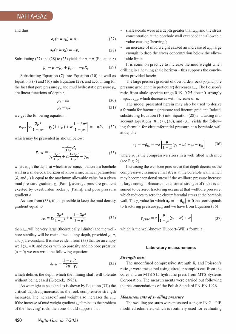
ratio μ were measured using circular samples cut from the cores and an MTS 815 hydraulic press from MTS Systems Corporation. The measurements were carried out following therecommendationsofthePolishStandardPN-EN1926.
Measurements of swelling pressureTheswellingpressuresweremeasuredusinganINiG–PIB
theswellingpressureofsiltyrockssubjectedtocompres-sion (Fig. 4). The test samples were made from ground silt/shale powder which was passed in advance through a sieve with an appropriate mesh. The silt/shale powder was used to produce tablets which were kept in a tight container to keep them at a constant humidity. These tablets were placed in a measuring cell where they were exposed to various liquids or solutions. The swelling pressures provided in this paper were measured using water, for which those pressures are the greatest. The results are presented in Table 1 together with calculation data for the analysed wells.
Examples of well stability calculationsIn the well E-1, drilled in the Carpathians, the heaving
shale was encountered in the depth interval of 1650–1750 m. We assume an average shale depth z of 1700 m. The shale’s compressive strength Rc – evaluated using cores from similar, nearbyshalerocks–was12MPaandtheaveragePoisson’sratio from full-phase sonic logs was 0.21. The pore pressure wasequalto20.7MPa.Theaveragedensityofoverburdenrocks was 2300 kg/m3 and the density of the mud in the well was 1200 kg/m3. We aimed to answer the following questions:a) Is it possible to maintain the mechanical integrity of shale
at this depth?The critical depth of shale is calculated using Equation (4):
zcrit = 1524 m
which shows that the stress concentration at the borehole wall at 1700 m is above the allowable limit since z > zcrit (which means that the actual shale depth z is greater than the critical depth), and so a shale with those strength properties is not able to maintain its integrity in such conditions (i.e. the actual mud density, average density of overburden rocks, rock mechanical parameters, and pore pressure gradient) which is manifested by shale crushing at the borehole wall.
b) What is the minimum mud density required to assure shale integrity at a specified depth?The minimum mud density required to maintain shale integ-rity at a depth z of 1700 m is calculated using Equation (5), in which the actual depth of the shale horizon is substituted for the critical depth.
����� � ���� �kgm��
The calculation indicates that the mud density should be increased from the actual mud density, 1200 kg/m3, to 1214 kg/ m3 in order to ensure shale integrity at z = 1700 m.
c) For which mud density would a shale with the above-specified strength properties preserve its integrity at any depth for a constant pore pressure gradient and a constant average density of overburden rocks?
The mud density for which a shale with these strength properties would preserve its integrity at any depth assum-ing constant ρs andαcanbecalculatedusingEquation(6):
����� � ����� �kgm��
The resulting value is the mud density for which stress con-centration at the borehole wall would not exceed the allowable limitatanydepthforshalewithspecifiedstrengthproperties,constant pore pressure gradient, and constant overburden pressure gradient.
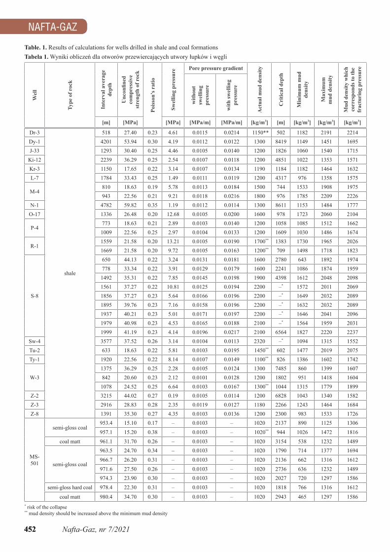
The results of calculations carried out using this procedure for severalwellsfromthesouthofPolandarepresentedinTable1.Theunconfinedcompressivestrengthandswellingpressuresweremeasured as described earlier. The calculations for some coal wells from Upper Silesia are also provided. In all cases the aver-age density of overburden rocks was assumed to be 2300 kg/m3.
As shown, the swelling pressure has a large impact on the pore pressure gradient. In the analysed samples the pore pressuregradientincreasedfrom0.0002to0.0099MPa/m.
For six of the analysed cases, the well instability was related to excessive depth and for the next six wells the mud density could be increased to solve the problem. In the case of coal deposits, the risk of well collapse was anticipated in one case, due to the excessive depth of the coal deposit.
Advantages and disadvantages of the presented approach
Advantages• The greatest merit of this approach is its simplicity. The
presented procedure allows us to tell whether the shale/coal will maintain its integrity at an actual depth z as well
Fig. 4. Apparatus for measuring the swelling pressure of silty rocks and shales (edometer)Rys. 4.Aparatdopomiaruciśnieniapęcznieniaskałilastychiłup-ków(edometr)
NAFTA-GAZ
452 Nafta-Gaz, nr 7/2021
NAFTA-GAZ
452
Table. 1. Results of calculations for wells drilled in shale and coal formationsTabela 1.Wynikiobliczeńdlaotworówprzewiercającychutworyłupkówiwęgli
coal matt 980.4 34.70 0.30 – 0.0103 – 1020 2943 465 1297 1586* risk of the collapse** mud density should be increased above the minimum mud density
artykuły
453Nafta-Gaz, nr 7/2021
artykuły
453
as the range of mud density that is required to eliminate wellbore stability problems.
Disadvantages• One never knows the true reason for shale problems – whether
they are mechanical in nature or are caused by the chemical interactionbetweenmudandshale/coal;thus,itisdifficulttoprovide numerous examples to support the conclusions pro-vided herein. We believe that the mechanical aspects should beconsideredfirst,sincewellstabilitycannotbeassured–regardless of the type of mud being used – if the combination of the mechanical properties and depth of the shale/coal and the mud density and pore pressure is not favourable.
• Thisapproachmaybeconsideredoversimplified,butitdoesallow for an approximation of some important practical values.
Conclusion
Itisdifficulttoindicateasinglereasonforlossofwellintegrity in a shale/coal interval since there are many factors whichinfluenceshale’sbehaviour–mudcompatibilitybeingthe most important. As mentioned above, the problem of well integrity in shales has been extensively discussed in the techni-cal literature. We believe that apart from mud chemistry and chemical interactions with shale, there are situations when a loss of shale integrity should be considered due to rock mechan-ics. Many models have been presented and numerous papers havedealtwithwellstabilityproblemsinshale(Lechnickij,1958; Bruce and Hall, 1986; Ottesen and Kwakwa, 1991; Santarelli et al, 1992; Mody and Hale, 1993; Van Oort et. al., 1994; Cook and Thiercelin, 1995; Lowrey and Ottesen, 1995; Santarelli and Carminati, 1995), but they share two common features:theyarecomplicatedanddifficulttouseinpractice.
The model presented herein, being quite simple, is easy to apply and the results seem reasonable.
Acknowledgments: The paper was prepared on the grounds ofinternationalprojectAdvanced methane drainage strategy-technology employing underground directional drilling technology for major risk prevention and greenhouse gases emission mitigation, which is co-founded by the programme of the Minister of Science and Higher Education entitled PMW in 2019–2022. Agreement no. 5038/FBWiS/2019/2.
Thisprojecthasreceivedco-fundingfromtheResearchFundforCoal and Steel under grant agreement no. 847338.
ReferencesBruce S., Hall C., 1986. The stability of boreholes. Drilling and Pumping
Journal.
Cook J., Thiercelin M., 1995. The mechanics of shale. Schlumberger Cambridge Research.
Gomez S., He W., 2012. Fighting Wellbore Instability: Customizing Drilling Fluids Based on Laboratory Studies of Shale-Fluid Interactions. IADC/SPE Asia Pacific Drilling Technology Conference and Exhibition, Tianjin, China. DOI: 10.2118/155536-MS.
2018.Characterizationofshale–fluidinteractionthroughaseriesof immersion tests and rheological studies. Journal of Petroleum Exploration and Production Technology, 8: 1273–1286. DOI: 10.1007/s13202-018-0444-5.
LyuQ.,RanjithP.G.,LongX.,KangY.,HuangM.,2015.Areviewofshaleswelling by water adsorption. Journal of Natural Gas Science and Engineering,27(11):1421–1431.DOI:10.1016/j.jngse.2015.10.004.
Mody F.K., Hale A.H., 1993. Borehole-Stability Model to Couple the Mechanics and Chemistry of Drilling-Fluid/Shale Interactions. Society of Petroleum Engineers,45(11):1093–1101.DOI:10.2118/25728-PA.
Ottesen S., Kwakwa K.A., 1991. Multidisciplinary Approach to in-situ Stress Determination and its Application to Wellbore Stability Analysis. Society of Petroleum Engineers SPE-21915-MS. DOI: 10.2118/21915-MS.
Santarelli F.J, Carminati S., 1995. Do shales swell? A critical review of available evidence. SPE Conference Paper. Society of Petroleum Engineers. DOI: 10.2118/29421-MS.
Santarelli F.J., Chenevert M.E., Osisanya S.O., 1992. On the stabil-ity of shales and its consequences in terms of swelling and well-bore stability. IADC/SPE Drilling Conference, New Orleans. DOI: 10.2118/23886-MS.
Van Oort E., Hale A.H., Mody F.K., 1994. Critical parameters in modelling the chemical aspects of borehole stability in shales and in designing improvedwater-basedshaledrillingfluids.SPE Annual Conference and Exhibition, New Orlean.ConferencePaper:171–186.
WangL.L.,ZhangG.Q.,HallaisS.,TanguyA.,YangD.S.,2017.Swellingof Shales: A Multiscale Experimental Investigation. Energy & Fuels: 31(10): 10442–10451. DOI: 10.1021/acs.energyfuels.7b01223.
Legislative acts and normative documentsStandardPN-EN1926:2007(PN-EN1926).Metodybadańkamie-