Multiphysics simulations of rocket engine combustion Yen-Sen Chen a,⇑ , T.H. Chou b , B.R. Gu b , J.S. Wu b , Bill Wu a , Y.Y. Lian a , Luke Yang a a National Space Organization, Hsinchu Science Park, Hsinchu, Taiwan b Department of Mechnical Engineering, National Chiao Tung University, Hsinchu, Taiwan article info Article history: Received 29 June 2010 Received in revised form 23 August 2010 Accepted 14 September 2010 Available online 19 September 2010 Keywords: Hybrid rocket combustion N 2 O–HTPB system Radiative heat transfer Real-fluid model Finite-rate chemistry abstract Recently, the hybrid rocket propulsion has become attractive to the research community and has devel- oped the trend to become an alternative to the conventional liquid and solid rockets. The hybrid rocket is a combination of both the solid and liquid systems with half of the plumbing of the liquid rocket but retaining its operational flexibility and avoiding the explosive nature of the solid rocket. Among available hybrid systems, the N 2 O (Nitrous Oxide)–HTPB (Hydroxyl-Terminated PolyButadiene) hybrid propulsion represents the simplest but sufficiently efficient design. Unfortunately, even until now, research in devel- oping hybrid N 2 O–HTPB propulsion system still strongly depends on trials-and-errors, which are time- consuming and expensive. Thus, detailed understanding of the fundamental combustion processes that are involved in the N 2 O–HTPB propulsion system can greatly impact the research community in this field. This may further facilitate the successful modeling of the combustion processes and help improving the design of N 2 O–HTPB propulsion system in the future. A comprehensive numerical model with real-fluid properties and finite-rate chemistry was developed in this research to predict the combustion flowfield inside a N 2 O–HTPB hybrid rocket system. Good numerical predictions as compared to experimental data are also presented. Ó 2010 Elsevier Ltd. All rights reserved. 1. Introduction In searching for payload mass fraction performance enhance- ment of human’s access to space technical capabilities, ramjet and scramjet (supersonic combustion ramjet) studies have been a long-term research effort in the aerospace community since the 1960s. Since the 1980s, computational modeling approaches have been gradually adopted in the aerospace community in the devel- opment of combustion devices and space launch systems. The advent of high performance computing infrastructures with im- proved computational techniques has turned complex numerical modeling methods, with substantial requirements in computa- tional resources, into practical daily design analysis tools. These advancements have allowed the researchers and designers of combustion devices to simulate the combustion processes and flow physics in detailed spatial and temporal resolutions that are very difficult and expensive to obtain using experimental means. Numerical models using computational fluid dynamics (CFD) methods have been applied to liquid and solid rocket combustion systems with successful supports to the technical programs [1–6]. Recent successes in flight demonstrations of the HyShot of the University of Queensland and Hyper-X of NASA, plus the flight test of Boeing X-51 in late 2009, have promoted greater research interests in computational modeling of advanced propulsion sys- tems. Numerical modeling efforts in simulating the supersonic combustion processes and the diagnoses of problem areas have contributed to the success of these programs. In the recent development of space launch systems, hybrid rocket propulsion has drawn a lot of attention, especially in the civilian space tourism community, and has been demonstrated to become a viable alternative to the liquid and solid rockets, although it is still in its fledgling stage as compared to the other two types of rockets. The liquid rocket is an efficient system; how- ever, it requires very complex and expensive plumbing systems. The solid rocket premixes the fuel and oxidizer as a grainy solid, which is dense and compact. However, it is highly explosive and lack of thrust control or termination. The hybrid rocket is a combi- nation of both the solid and liquid systems with half of the plumb- ing of the liquid rockets, but retaining their flexibility of operation and avoiding the explosive nature of the solid rockets. The major advantages of the hybrid rockets include [7]: (1) safety without explosive concern, (2) flexibility in throttling and termination, (3) grain robustness without the danger of explosion originating from cracks, (4) propellant versatility, (5) temperature insensitivity to the operating chamber pressure, and (6) low cost benefiting from the safety features. Nevertheless, there are several disadvantages which include [7]: (1) low regression rate (1 mm/s) due to the nature of the diffusion flame, (2) low bulk density (low volumetric 0045-7930/$ - see front matter Ó 2010 Elsevier Ltd. All rights reserved. doi:10.1016/j.compfluid.2010.09.010 ⇑ Corresponding author. E-mail addresses: [email protected](Y.-S. Chen), [email protected]. edu.tw (J.S. Wu). Computers & Fluids 45 (2011) 29–36 Contents lists available at ScienceDirect Computers & Fluids journal homepage: www.elsevier.com/locate/compfluid
Multiphysics simulations of rocket engine combustion
Yen-Sen Chen a,⇑, T.H. Chou b, B.R. Gu b, J.S. Wu b, Bill Wu a, Y.Y. Lian a, Luke Yang a
a National Space Organization, Hsinchu Science Park, Hsinchu, Taiwanb Department of Mechnical Engineering, National Chiao Tung University, Hsinchu, Taiwan
a r t i c l e i n f o a b s t r a c t
Article history:Received 29 June 2010Received in revised form 23 August 2010Accepted 14 September 2010Available online 19 September 2010
Recently, the hybrid rocket propulsion has become attractive to the research community and has devel-oped the trend to become an alternative to the conventional liquid and solid rockets. The hybrid rocket isa combination of both the solid and liquid systems with half of the plumbing of the liquid rocket butretaining its operational flexibility and avoiding the explosive nature of the solid rocket. Among availablehybrid systems, the N2O (Nitrous Oxide)–HTPB (Hydroxyl-Terminated PolyButadiene) hybrid propulsionrepresents the simplest but sufficiently efficient design. Unfortunately, even until now, research in devel-oping hybrid N2O–HTPB propulsion system still strongly depends on trials-and-errors, which are time-consuming and expensive. Thus, detailed understanding of the fundamental combustion processes thatare involved in the N2O–HTPB propulsion system can greatly impact the research community in this field.This may further facilitate the successful modeling of the combustion processes and help improving thedesign of N2O–HTPB propulsion system in the future. A comprehensive numerical model with real-fluidproperties and finite-rate chemistry was developed in this research to predict the combustion flowfieldinside a N2O–HTPB hybrid rocket system. Good numerical predictions as compared to experimental dataare also presented.
� 2010 Elsevier Ltd. All rights reserved.
1. Introduction
In searching for payload mass fraction performance enhance-ment of human’s access to space technical capabilities, ramjetand scramjet (supersonic combustion ramjet) studies have been along-term research effort in the aerospace community since the1960s. Since the 1980s, computational modeling approaches havebeen gradually adopted in the aerospace community in the devel-opment of combustion devices and space launch systems. Theadvent of high performance computing infrastructures with im-proved computational techniques has turned complex numericalmodeling methods, with substantial requirements in computa-tional resources, into practical daily design analysis tools. Theseadvancements have allowed the researchers and designers ofcombustion devices to simulate the combustion processes and flowphysics in detailed spatial and temporal resolutions that are verydifficult and expensive to obtain using experimental means.Numerical models using computational fluid dynamics (CFD)methods have been applied to liquid and solid rocket combustionsystems with successful supports to the technical programs[1–6]. Recent successes in flight demonstrations of the HyShot ofthe University of Queensland and Hyper-X of NASA, plus the flight
test of Boeing X-51 in late 2009, have promoted greater researchinterests in computational modeling of advanced propulsion sys-tems. Numerical modeling efforts in simulating the supersoniccombustion processes and the diagnoses of problem areas havecontributed to the success of these programs.
In the recent development of space launch systems, hybridrocket propulsion has drawn a lot of attention, especially in thecivilian space tourism community, and has been demonstrated tobecome a viable alternative to the liquid and solid rockets,although it is still in its fledgling stage as compared to the othertwo types of rockets. The liquid rocket is an efficient system; how-ever, it requires very complex and expensive plumbing systems.The solid rocket premixes the fuel and oxidizer as a grainy solid,which is dense and compact. However, it is highly explosive andlack of thrust control or termination. The hybrid rocket is a combi-nation of both the solid and liquid systems with half of the plumb-ing of the liquid rockets, but retaining their flexibility of operationand avoiding the explosive nature of the solid rockets. The majoradvantages of the hybrid rockets include [7]: (1) safety withoutexplosive concern, (2) flexibility in throttling and termination, (3)grain robustness without the danger of explosion originating fromcracks, (4) propellant versatility, (5) temperature insensitivity tothe operating chamber pressure, and (6) low cost benefiting fromthe safety features. Nevertheless, there are several disadvantageswhich include [7]: (1) low regression rate (�1 mm/s) due to thenature of the diffusion flame, (2) low bulk density (low volumetric
fuel loading) due to many ports for increasing grain surface area,(3) low combustion efficiency, (4) O/F shift with burning timeand location, and (5) slower transient response to throttling.
There are many types of hybrid combustion systems, in whichfuel is classically a solid and the oxidizer is a liquid or gas. Theseinclude different solid fuels such as hydrocarbons (rubbers, plasticsand even papers) and metals, and a wide variety of liquid oxidizerssuch as oxygen, hydrogen peroxide, nitric acid, nitrogen tetroxide,and nitrous oxide. Typical examples of combination of fuel and oxi-dizer with optimum O/F, Isp (184–326 s) and characteristic veloc-ity (1224–2118 m/s) are discussed in Ref. [7]. Among these, mostexperimental data were published for propellants using LOX andHTBP with or without aluminum powder. Although no detaileddata were available in the literature for the hybrid propellantsusing nitrous oxide as the oxidizer and HTBP related materials asthe fuel, recent development of most commercial companies tendsto utilize this combination, e.g. the SpaceShip One (led by Burt Ru-tan) which won the X Prize in September 2004 by flying up to analtitude of 100 km and landing safely back to Earth. The maximumvacuum Isp of the N2O–HTPB propulsion system is only fair around250 s; however, it represents the simplest one, mainly due to theself-pressurization feature of the nitrous oxide (�60 bar at roomtemperature), which greatly simplifies the plumbing systems.Unfortunately, even until now, research in developing the hybridN2O–HTPB propulsion system still strongly depends on trials-and-errors, which are time-consuming and expensive. Very few[8,9] have attempted to model complicated reactive flow phenom-ena of a realistic hybrid propulsion system, in which they employan energy-balanced surface decomposition model with theassumption that decomposition of C4H6 (Iso-butadiene) starts at820 K, and modeled the combustion process using some reducedreaction mechanisms with tuned rate constants.
The above modeling efforts have reached success to some ex-tent based on fitting of experiments and numerical simulations.However, the real-fluid effects were not considered in their mod-els. This can affect the overall flow structure in the combustionchamber, especially near the injectors, and affect the combustionprocesses and heat transfer characteristics, which is the key tothe regression rates of the solid grain. Thus, a comprehensivenumerical model is developed in this research to include thereal-fluid property effects and finite-rate chemistry in the simula-tion of an N2O–HTPB hybrid rocket system.
2. Method of approach
The present numerical method solves a set of governing equa-tions describing the conservation of mass, momentum (Navier–Stokes equations), energy, species concentration and turbulencequantities. The governing equations are written as:
@q@tþ @
@xjðqujÞ ¼ 0 ð1Þ
@qai
@tþ @
@xjðqujajÞ ¼
@
@xjqDþ lt
ra
� �@ai
@xj
� �þxi ð2Þ
@qui
@tþ @
@xjðqujuiÞ ¼ �
@p@xiþ @sij
@xjð3Þ
@qH@tþ @
@xjðqujHÞ ¼
@p@tþ Q r þ
@
@xj
KCpþ lt
rH
� �rH
� �
þ @
@xjðlþ ltÞ �
KCpþ lt
rH
� �� �rðV2=2Þ
� �
þ @
@xj
KCpþ lt
rH
� �uk@uj
@xk� 2
3uj@uk
@xk
� �� �ð4Þ
@qk@tþ @
@xjðqujkÞ ¼
@
@xjlþ lt
rk
� �@k@xj
� �þ qðP� eÞ ð5Þ
@qe@tþ @
@xjðqujeÞ ¼
@
@xjlþ lt
re
� �@e@xj
� �
þ qek
C1P� C2eþ C3P2=e
� �ð6Þ
The convection terms of the governing equations are discretizedwith a second-order upwind scheme. Second-order centralschemes are applied to the diffusion and source terms. For com-plete description of the thermal environment in the combustionchamber, a radiative heat transfer model with a finite-volume inte-gration method [1,4] is also employed in the present model. In thecombustion chamber, the main participating species in the radia-tion model are carbon-dioxide and hot steam. For transient flowcomputations, an efficient second-order time-marching scheme,which has been validated for vortex shedding and transientstart-up nozzle flows [6], is employed in the present study. An effi-cient method for comprehensive real-fluid equations of state andfluid properties is also tested for liquid propellant combustionflows. These numerical models are important for high fidelity sim-ulations of combustion physics. They are described in the followingsections.
2.1. Radiative heat transfer model
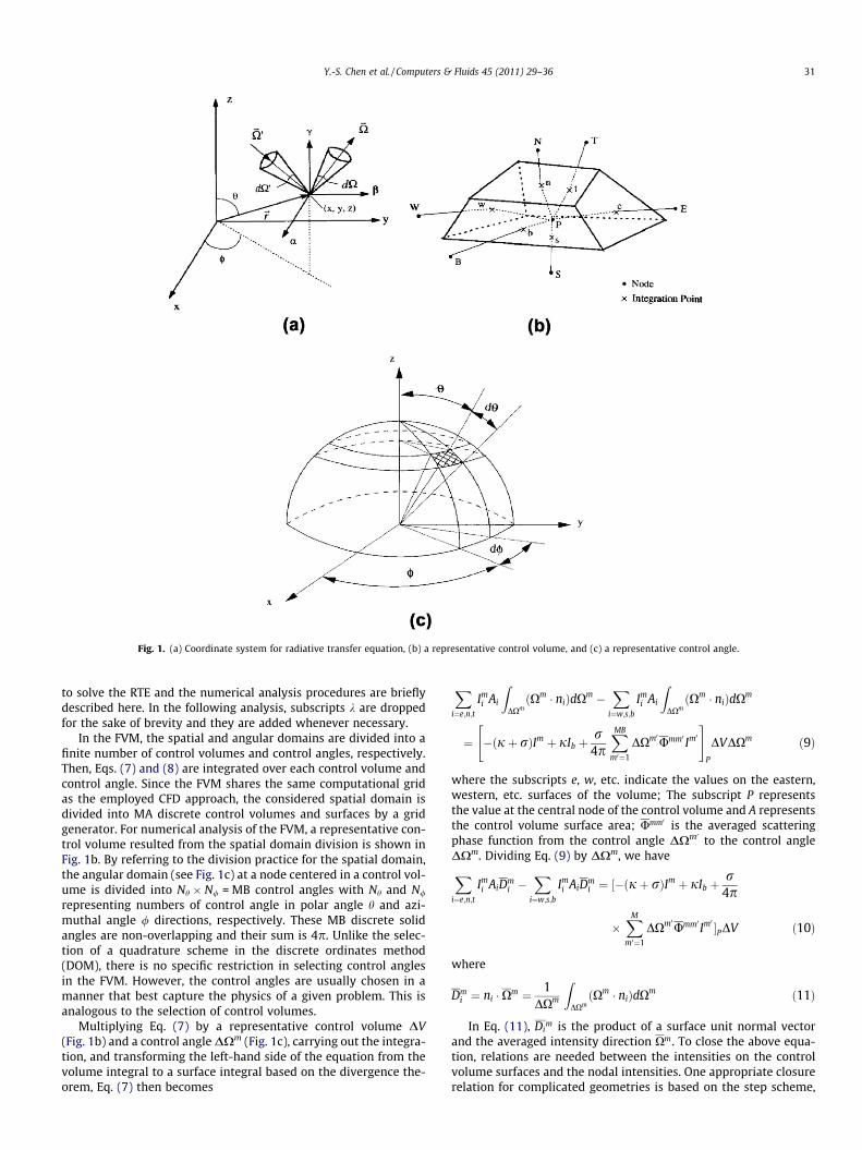
Radiation effects are important for combustion simulationswhen radiative participating species appear in the combustionproducts and in the pyrolysis gas decomposed from the solid pro-pellant. Radiative transfer model using a finite-volume integrationmethod is employed in this study [10,11]. Consider the radiativetransfer equation (RTE) in a Cartesian coordinate system as shownin Fig. 1a. The balance of energy passing in a specified direction Xthrough a small differential volume in an absorbing–emitting andscattering medium can be written as:
ðX � rÞIkðr;XÞ ¼ �ðjk þ rkÞIkðr;XÞ þ jkIb;kðrÞ
þ rk
4p
Z0¼4p
Ikðr;X0ÞkðX0 ! XÞd0 ð7Þ
where the subscript k represents the wave-number; Ikðr;XÞ is thespectral radiative intensity, which is a function of position r andangular direction X; Ib;kðrÞ is the blackbody radiative intensity atthe temperature of the medium; j k and r k are the spectral absorp-tion and scattering coefficients, respectively; and UkðX0 ! XÞ is thescattering phase function from the incoming X0 direction to the out-going direction X; and d0 indicates integration over a 4p angulardirections. The term on the left-hand side represents the gradientof the intensity in the direction X. The three terms on the right handside represent the changes in intensity due to absorption andout-scattering, emission and in-scattering, respectively. If the wallbounding the medium emits and reflects diffusely, then the radia-tive boundary condition for Eq. (7) is given by
Ikðrw;XþÞ ¼ ekIb;kðrwÞ þ
ð1� ekÞp
Zn�X�<0
Ikðrw;X�Þjn �X�jd� ð8Þ
where Xþ and X� denote the leaving and arriving radiative intensitydirections, respectively; ek is the spectral wall emissivity; n repre-sents the unit normal vector on the wall; d� indicates integrationover all angles of the arriving directions. Eq. (7) is a complex inte-gro-differential equation whose exact analytical solution is onlypossible for very simple and specific settings. This intrinsic diffi-culty has resulted in the development of several approximatedmodels. In the present model, a finite volume method (FVM) is used
Fig. 1. (a) Coordinate system for radiative transfer equation, (b) a representative control volume, and (c) a representative control angle.
to solve the RTE and the numerical analysis procedures are brieflydescribed here. In the following analysis, subscripts k are droppedfor the sake of brevity and they are added whenever necessary.
In the FVM, the spatial and angular domains are divided into afinite number of control volumes and control angles, respectively.Then, Eqs. (7) and (8) are integrated over each control volume andcontrol angle. Since the FVM shares the same computational gridas the employed CFD approach, the considered spatial domain isdivided into MA discrete control volumes and surfaces by a gridgenerator. For numerical analysis of the FVM, a representative con-trol volume resulted from the spatial domain division is shown inFig. 1b. By referring to the division practice for the spatial domain,the angular domain (see Fig. 1c) at a node centered in a control vol-ume is divided into Nh � N/ = MB control angles with Nh and N/
representing numbers of control angle in polar angle h and azi-muthal angle / directions, respectively. These MB discrete solidangles are non-overlapping and their sum is 4p. Unlike the selec-tion of a quadrature scheme in the discrete ordinates method(DOM), there is no specific restriction in selecting control anglesin the FVM. However, the control angles are usually chosen in amanner that best capture the physics of a given problem. This isanalogous to the selection of control volumes.
Multiplying Eq. (7) by a representative control volume DV(Fig. 1b) and a control angle DXm (Fig. 1c), carrying out the integra-tion, and transforming the left-hand side of the equation from thevolume integral to a surface integral based on the divergence the-orem, Eq. (7) then becomes
Xi¼e;n;t
Imi Ai
ZDXmðXm � niÞdXm �
Xi¼w;s;b
Imi Ai
ZDXmðXm � niÞdXm
¼ �ðjþ rÞIm þ jIb þr
4pXMB
m0¼1
DXm0Umm0 Im0
" #P
DVDXm ð9Þ
where the subscripts e, w, etc. indicate the values on the eastern,western, etc. surfaces of the volume; The subscript P representsthe value at the central node of the control volume and A representsthe control volume surface area; Umm0 is the averaged scatteringphase function from the control angle DXm0 to the control angleDXm. Dividing Eq. (9) by DXm, we haveXi¼e;n;t
Imi AiDm
i �X
i¼w;s;b
Imi AiDm
i ¼ ½�ðjþ rÞIm þ jIb þr
4p
�XM
m0¼1
DXm0Umm0 Im0 �PDV ð10Þ
where
Dmi ¼ ni �Xm ¼ 1
DXm
ZDXmðXm � niÞdXm ð11Þ
In Eq. (11), Dim is the product of a surface unit normal vector
and the averaged intensity direction Xm. To close the above equa-tion, relations are needed between the intensities on the controlvolume surfaces and the nodal intensities. One appropriate closurerelation for complicated geometries is based on the step scheme,
which sets the downstream surface intensities equal to the up-stream nodal intensities. Use of the step scheme avoids the nega-tive intensities, overshoots, and undershoots which may occur inother radiation schemes such as the diamond scheme, and positivescheme. Furthermore it has much less connection with the neigh-boring nodes, and thus it is particularly suitable for parallel com-putation. The effect of the step scheme on communication costsis not significant. The final discretized equation for the FVM canbe written as
amP Im
P ¼ amE Im
E þ amW Im
W þ amN Im
N þ amS Im
S þ amT Im
T þ amB Im
B þ bm ð12Þ
where the intensities with the subscripts E, W, etc. denote the east-ern, western, etc. nodal intensities, and
amP ¼
Xi¼e;n;t
maxðAiDmi ;0Þ �
Xi¼w;s;b
minðAiDmi ;0Þ þ DVðjþ rÞ ð13aÞ
amI ¼ �minðAiDm
i ;0Þ i ¼ e;n; t and I ¼ E;N; T ð13bÞ
amI ¼maxðAiDm
i ;0Þ i ¼ w; s; b and I ¼W; S;B ð13cÞ
bm ¼ DV jIb þr
4pXMB
m0¼1
DXm0Umm0 Im0
" #P
ð13dÞ
The preceding discretization is carried out along only one con-trol angle at a node. The same procedure should be applied to allof the MB control angles at all of the MA nodes. This forms MA�MBsystems of non-symmetric algebraic equations. A solution of theseequations only represents radiative contribution at a single wavenumber. The radiative divergence is the quantity used in the en-ergy equation and it should consist of radiative contributions fromall wave numbers. The radiative divergence is expressed in termsof the radiative intensities as
r � qr ¼Z 1
0�jk
Z 4p
0Ikdxþ jk
Z 4p
0Ib;kdx
� �dk
¼Z 1
04pjkIb;k � jk
XMB
m¼1
Imk DXm
" #dk ð14Þ
A typical radiatively participating gas consists of many lineswhose absorption coefficients vary rapidly with wave number.Thus, it becomes a very difficult and time-consuming to evaluatethe radiative properties over the actual band contour and includethem into the RTE. To avoid this difficulty, the spectrum can be di-vided into MC bands and the radiative properties are assumed con-stant over each band. The integrated quantity in Eq. (14) is found asthe summation over all bands of the individual contribution foreach band, that is,
r � qr ¼Xj¼MC
j¼1
4pkjjIbj � jj
XMB
m¼1
Imk DXm
" #Dkj ð15Þ
The above approach to the spectral problem essentially corre-sponds to the spectral discretization and it represents a good com-promise between accuracy and computational time. The number ofMC can be changed from one (gray gas model) to several hundred(narrow band model). Obviously, the use of higher MC numberprovides more accurate results.
2.2. Transient time-marching scheme
In the present numerical model, the temporal terms of thetransport equations are modeled with a second-order backwarddifference scheme. There are two ways of performing time-march-ing procedures. First, the momentum, energy and pressure-correc-tion equations are grouped together within an iteration loop and
drive to convergence for each time step. Although the transientsub-iteration method described in the previous section is accuratefor transient flow applications, it requires many sub-iterations(more for highly dynamic cases) to advance one time step, espe-cially for low-speed flows. In order to save computational effortin transient flow applications, this sub-iteration algorithm can bereplaced with a more efficient method, such as the operator split-ting technique [12–14]. This method consists of a predictor stepplus two corrector steps to drive the discretization errors to sec-ond-order accuracy.
Testing of the transient model is described in the following sec-tions. Some test cases are identified for time accurate modelingand data comparisons. They are: (1) the laminar and turbulent vor-tex shedding flows behind a circular cylinder; and (2) unsteadymulti-species flows past a circular cylinder with and withoutchemical reactions. The mesh and test conditions for these casesare prepared with initial uniform flow conditions. Proper time stepsizes were selected for good solutions of these transient cases.Knowing the cycle time period from the experimental data, thecomputational time step size is then determined such that thereare at least 200 time steps within one cycle. For cases withoutexperimental data a priori, grid and time-step convergence testsare required numerically. This is a good guideline based on previ-ous experience although some adjustment may be needed for spe-cial cases with multiple dominant frequencies and/or frequencymodulations.
2.3. Real-fluid combustion modeling
In order to perform analyses of phase change phenomena incavitation, liquid sprays or cryogenic fluid flows, real-fluid thermaland caloric equations of state (EOS) were developed for use withthe present CFD code. The HBMS equations of state [15–17] werechosen for this purpose. Thermal and caloric equations of state, va-por pressure, heat of vaporization, surface tension, and transportproperties are modeled with the equations of state proposed byHirshfelder et al., as employed by Dooley [18] and Anon. [19](we term these the HBMS equations of state), and with conven-tional correlations [20] for the other properties. The property cor-relations used were not chosen for their absolute accuracy, but fortheir validity over a wide range of temperatures and pressures andfor requiring a minimum of data to describe a particular species.These correlations are explicit in density and temperature. Theseequations are:
HBMS thermal equation of state:
PPc¼X4
j¼1
Tj�2r
X6
i¼1
Bijqi�2r ; Tr ¼
TTc
; qr ¼qqc
HBMS caloric equation of state:
H � H0
RT¼ Zc
Z qr
0
PTr� @P
@Tr
� �qr
" #q�2
r dqr þ ZcP
qrTr� 1
These equations are not only of sufficiently high order thatproperties are accurately predicted for a wide range of conditions,but component sub-models may be easily modified. In this in-stance, the vapor pressure curve and the liquid phase density cor-relations were improved over the original HBMS formulations.Other equations of state were considered, but were found not tobe as satisfactory as the HBMS equations.
Multi-component mixtures were treated by adding partial spe-cific volumes or pressures. The partial volume methodology isessential to improve the accuracy of the prediction when a smallamount of multi-component vapor and a large amount of liquidare present at the same point. The fluid property routines also
include correlations for the transport properties. This was conve-nient since much of the methodology was similar.
2.4. Real-fluid model computational speed
In assessing the computational overhead associated with usingthe real-fluid property sub-model, numerical experiments of simu-lating some converging–diverging pipe flows with ideal gas and li-quid oxygen working fluids were conducted to quantify the CPUtime overhead when the real-fluid model is activated. The resultsshow an overall CPU time increase of about 85% for the real-fluidcases. These results indicate that there are rooms for improvementin order to enhance the turnaround time of running multi-phaseflow problems. To improve the computational efficiency, a real-fluid table lookup procedure was developed for the present CFDmodel. This method is much more efficient than the originalreal-fluid model which involves the inversion of curve-fit datadescribing the equation of state. In average, the real-fluid tablelookup model is only 15% slower than its ideal-gas counterpart.This means about 70% saving in CPU time with the real-fluid tablelookup method.
2.5. Multi-species mixture implementation
For general applications of the present table-lookup real-fluidmodel, one must consider the conditions of multi-species mixingprocesses. To streamline the modeling approach for better perfor-mance in terms of computational efficiency and program codingclarity, functions for calculating enthalpy, specific heat and densityare created based on the current code structure of the present CFDmodel. These new functions now consist of extra sections for thereal-fluid properties based on the local pressure, temperatureand species concentrations. The table lookup section is activatedwhen the temperature is lower than the value that divides thereal-fluid and perfect gas properties. Within the table lookup sec-tion, the pressure level is first used to define a property curvebased on the database provided. Then, the fluid property is ob-tained through interpolation based on this new curve.
3. Real-fluid model combustion test
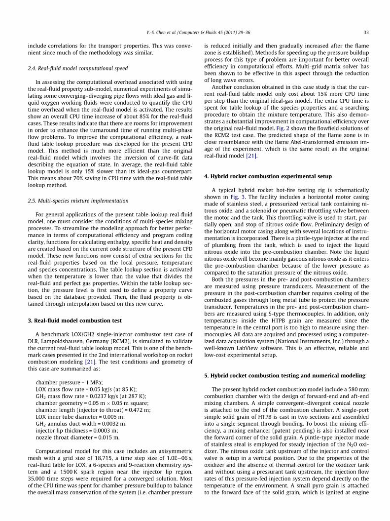
A benchmark LOX/GH2 single-injector combustor test case ofDLR, Lampoldshausen, Germany (RCM2), is simulated to validatethe current real-fluid table lookup model. This is one of the bench-mark cases presented in the 2nd international workshop on rocketcombustion modeling [21]. The test conditions and geometry ofthis case are summarized as:
chamber pressure = 1 MPa;LOX mass flow rate = 0.05 kg/s (at 85 K);GH2 mass flow rate = 0.0237 kg/s (at 287 K);chamber geometry = 0.05 m � 0.05 m square;chamber length (injector to throat) = 0.472 m;LOX inner tube diameter = 0.005 m;GH2 annulus duct width = 0.0032 m;injector lip thickness = 0.0003 m;nozzle throat diameter = 0.015 m.
Computational model for this case includes an axisymmetricmesh with a grid size of 18,715, a time step size of 1.0E�06 s,real-fluid table for LOX, a 6-species and 9-reaction chemistry sys-tem and a 1500 K spark region near the injector lip region.35,000 time steps were required for a converged solution. Mostof the CPU time was spent for chamber pressure buildup to balancethe overall mass conservation of the system (i.e. chamber pressure
is reduced initially and then gradually increased after the flamezone is established). Methods for speeding up the pressure buildupprocess for this type of problem are important for better overallefficiency in computational efforts. Multi-grid matrix solver hasbeen shown to be effective in this aspect through the reductionof long wave errors.
Another conclusion obtained in this case study is that the cur-rent real-fluid table model only cost about 15% more CPU timeper step than the original ideal-gas model. The extra CPU time isspent for table lookup of the species properties and a searchingprocedure to obtain the mixture temperature. This also demon-strates a substantial improvement in computational efficiency overthe original real-fluid model. Fig. 2 shows the flowfield solutions ofthe RCM2 test case. The predicted shape of the flame zone is inclose resemblance with the flame Abel-transformed emission im-age of the experiment, which is the same result as the originalreal-fluid model [21].
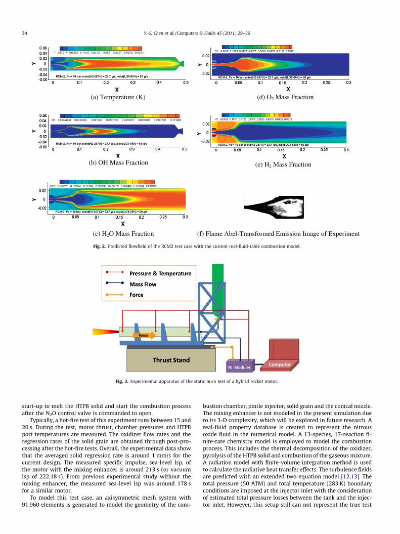
4. Hybrid rocket combustion experimental setup
A typical hybrid rocket hot-fire testing rig is schematicallyshown in Fig. 3. The facility includes a horizontal motor casingmade of stainless steel, a pressurized vertical tank containing ni-trous oxide, and a solenoid or pneumatic throttling valve betweenthe motor and the tank. This throttling valve is used to start, par-tially open, and stop of nitrous oxide flow. Preliminary design ofthe horizontal motor casing along with several locations of instru-mentation is incorporated. There is a pintle-type injector at the endof plumbing from the tank, which is used to inject the liquidnitrous oxide into the pre-combustion chamber. Note the liquidnitrous oxide will become mainly gaseous nitrous oxide as it entersthe pre-combustion chamber because of the lower pressure ascompared to the saturation pressure of the nitrous oxide.
Both the pressures in the pre- and post-combustion chambersare measured using pressure transducers. Measurement of thepressure in the post-combustion chamber requires cooling of thecombusted gases through long metal tube to protect the pressuretransducer. Temperatures in the pre- and post-combustion cham-bers are measured using S-type thermocouples. In addition, onlytemperatures inside the HTPB grain are measured since thetemperature in the central port is too high to measure using ther-mocouples. All data are acquired and processed using a computer-ized data acquisition system (National Instruments, Inc.) through awell-known LabView software. This is an effective, reliable andlow-cost experimental setup.
5. Hybrid rocket combustion testing and numerical modeling
The present hybrid rocket combustion model include a 580 mmcombustion chamber with the design of forward-end and aft-endmixing chambers. A simple convergent–divergent conical nozzleis attached to the end of the combustion chamber. A single-portsimple solid grain of HTPB is cast in two sections and assembledinto a single segment through bonding. To boost the mixing effi-ciency, a mixing enhancer (patent pending) is also installed nearthe forward corner of the solid grain. A pintle-type injector madeof stainless steal is employed for steady injection of the N2O oxi-dizer. The nitrous oxide tank upstream of the injector and controlvalve is setup in a vertical position. Due to the properties of theoxidizer and the absence of thermal control for the oxidizer tankand without using a pressurant tank upstream, the injection flowrates of this pressure-fed injection system depend directly on thetemperature of the environment. A small pyro grain is attachedto the forward face of the solid grain, which is ignited at engine
O)d()K(erutarepmeT)a( 2 Mass Fraction
H)e(noitcarFssaMHO)b(2 Mass Fraction
(c) H2O Mass Fraction (f) Flame Abel-Transformed Emission Image of Experiment
Fig. 2. Predicted flowfield of the RCM2 test case with the current real-fluid-table combustion model.
Fig. 3. Experimental apparatus of the static burn test of a hybrid rocket motor.
start-up to melt the HTPB solid and start the combustion processafter the N2O control valve is commanded to open.
Typically, a hot-fire test of this experiment runs between 15 and20 s. During the test, motor thrust, chamber pressures and HTPBport temperatures are measured. The oxidizer flow rates and theregression rates of the solid grain are obtained through post-pro-cessing after the hot-fire tests. Overall, the experimental data showthat the averaged solid regression rate is around 1 mm/s for thecurrent design. The measured specific impulse, sea-level Isp, ofthe motor with the mixing enhancer is around 213 s (or vacuumIsp of 222.18 s). From previous experimental study without themixing enhancer, the measured sea-level Isp was around 178 sfor a similar motor.
To model this test case, an axisymmetric mesh system with91,960 elements is generated to model the geometry of the com-
bustion chamber, pintle injector, solid grain and the conical nozzle.The mixing enhancer is not modeled in the present simulation dueto its 3-D complexity, which will be explored in future research. Areal-fluid property database is created to represent the nitrousoxide fluid in the numerical model. A 13-species, 17-reaction fi-nite-rate chemistry model is employed to model the combustionprocess. This includes the thermal decomposition of the oxidizer,pyrolysis of the HTPB solid and combustion of the gaseous mixture.A radiation model with finite-volume integration method is usedto calculate the radiative heat transfer effects. The turbulence fieldsare predicted with an extended two-equation model [12,13]. Thetotal pressure (50 ATM) and total temperature (283 K) boundaryconditions are imposed at the injector inlet with the considerationof estimated total pressure losses between the tank and the injec-tor inlet. However, this setup still can not represent the true test
conditions because the real inlet conditions are transient in nature.During the test, the tank pressure and temperature are reducedrapidly due to high flow rate and the expansion effects. Therefore,in the present model, we compare the numerical predictions to thetest data when the oxidizer injection stays in the liquid phase, i.e.between 2 and 7 s after ignition.
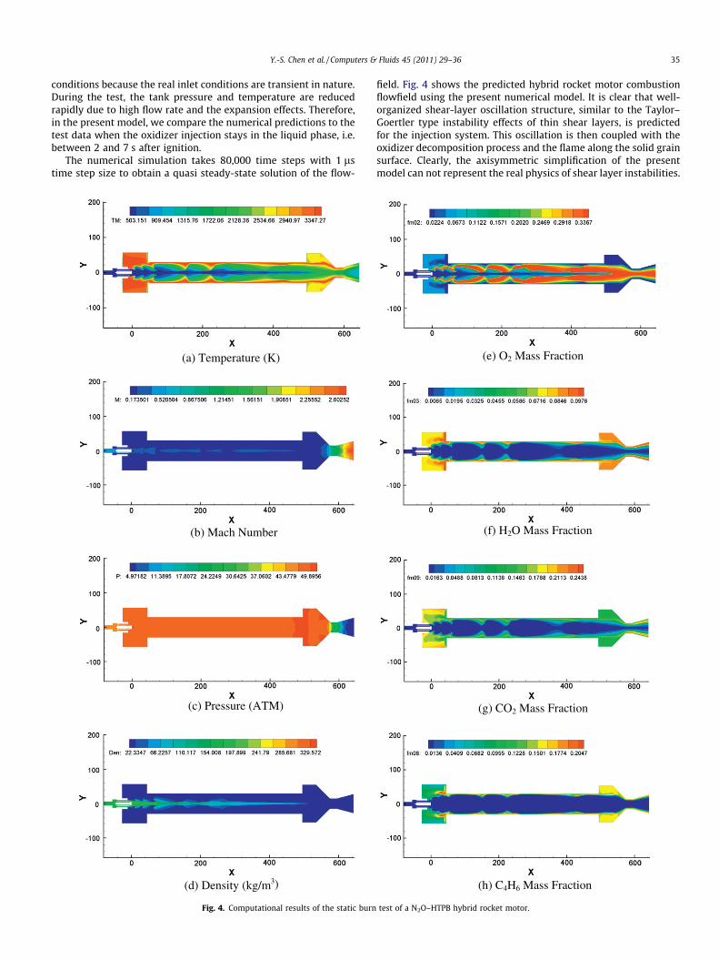
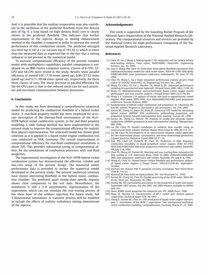
The numerical simulation takes 80,000 time steps with 1 lstime step size to obtain a quasi steady-state solution of the flow-
)K(erutarepmeT)a(
rebmuNhcaM)b(
)MTA(erusserP)c(
(d) Density (kg/m3)
Fig. 4. Computational results of the static burn
field. Fig. 4 shows the predicted hybrid rocket motor combustionflowfield using the present numerical model. It is clear that well-organized shear-layer oscillation structure, similar to the Taylor–Goertler type instability effects of thin shear layers, is predictedfor the injection system. This oscillation is then coupled with theoxidizer decomposition process and the flame along the solid grainsurface. Clearly, the axisymmetric simplification of the presentmodel can not represent the real physics of shear layer instabilities.
And, it is plausible that the oxidizer evaporation may also contrib-ute to the oscillation of the predicted flowfield. From the densityplot of Fig. 4, a long liquid (or high density fluid) core is clearlyshown in the predicted flowfield. This indicates that furtherimprovement in the injector design or mixing enhancementmethod in the chamber is required in order to increase the overallperformance of this combustion system. The predicted averagedsea-level Isp is 181.2 s (or vacuum Isp of 191.18 s), which is lowerthan the measured data as expected due to the fact that a mixingenhancer is not present in the numerical model.
To increase computational efficiency of the present complexmodel with multiphysics capabilities, parallel computation is em-ployed on an IBM cluster computer system. Classes of 8-CPU, 32-CPU and 64-CPU were tested in the study. Results show parallelefficiency of around 0.97 (7.76 times speed up), 0.86 (27.52 timesspeed up) and 0.71 (45.44 times speed up), respectively, for thesethree classes of runs. The sharp decrease in parallel efficiency forthe 64-CPU cases is due to the reduced mesh size for each proces-sor and increased communication between processors.
6. Conclusions
In this study, we have developed a comprehensive numericalmodel for predicting the combustion flowfield of a hybrid rocketmotor. A real-fluid property model has been employed for accu-rate description of the thermal-fluid environment of the N2O–HTPB hybrid rocket combustion system. In the real-fluid propertymodeling, a table lookup method has been implemented in thepresent study to improve the computational efficiency for realisticflow physics representation. The improved model has shown goodsolutions as it is applied to a liquid rocket engine combustion testcase conducted at DLR, Germany. The overall improvement incomputational efficiency for real-fluid combustion simulations isabout 70%. This provides substantial saving in computational ef-forts for the simulations of combustion processes with real-fluidproperties.
The experimental investigation of the N2O–HTPB hybrid rocketcombustion system has demonstrated the effective, reliable andlow-cost setup of the present design. The measured motorperformance data is provided to anchor the numerical modeldeveloped in the present study. The present numerical solutionshave shown interesting flowfield in the hybrid motor combus-tion chamber. The predicted quasi steady-state specific impulseshows close comparison to the test data. Nevertheless, thesimulation is still a 2-D axisymmetric representation of theexperiment, which can not simulate the true mixing process ofthe shear layer of the oxidizer injection. For future study, full3-dimensional simulations in transient process will be modeledto include the effects of realistic turbulence mixing downstreamof the injector.
Acknowledgements
This work is supported by the Sounding Rocket Program of theNational Space Organization of the National Applied Research Lab-oratory. The computational resources and services are provided bythe National Center for High-performance Computing of the Na-tional Applied Research Laboratory.
References
[1] Chen YS, Liu J, Zhang S, Mallapragada P. An integrated tool for launch vehiclebase-heating analysis. Final report, NAS8-00002. Huntsville: EngineeringSciences, Inc., AL; 2001.
[2] Liaw P, Shang HM, Chen YS. Particulate multi-phase flowfield calculation withcombustion/breakup models for solid rocket motor. AIAA-94-2780, 30th AIAA/ASME/SAE/ASEE joint propulsion conference, Indianapolis, IN, June 27–29,1994.
[3] Chen YS, Zhang S, Liu J. Stage separation performance analysis project. Finalreport, H-34345D. Huntsville, AL: Engineering Sciences, Inc.; 2002.
[4] Wang TS, Chen YS, Liu J, Myrabo LN, Mead Jr FB. Advanced performancemodeling of experimental laser lightcraft. J Propul Power 2002;18(6):1129–38.
[5] Wang TS. Multidimensional unstructured-grid liquid rocket engine nozzleperformance and heat transfer analysis. J Propul Power 2005;22(1):78–84.
[6] Wang T-S. Transient 3-D analysis of nozzle side load in regeneratively cooledengines. AIAA paper 2005-3942, 41st AIAA/ASME/SAE/ASEE joint propulsionconference, Tucson, Arizona; 2005.
[7] Fundamentals of hybrid rocket combustion and propulsion. In: Chiaverini MI,Kuo KK, editors. Progress in astronautics and aeronautics, vol. 218; 2007.
[8] Farmer RC, Cheng GC, Jones SH, Arves JP. A practical CFD model for simulatinghybrid motors. JANNAF 35th combustion, airbreathing propulsion, andpropulsion systems hazards subcommittee joint meeting, Tucson, AZ, 1998.
[10] Liu JW, Chen YS. Parallel simulation of radiative heat transfer using anunstructured finite-volume method. Numer Heat Transf B 1999;36:115–37.
[11] Liu JW, Chen YS. Development of an unstructured radiation model applicablefor two-dimensional planar, axisymmetric and three-dimensional geometries.J Quant Spectrosc Radiative Transf 2000;22:17–33.
[12] Kim YM, Chen CP, Ziebarth JP, Chen YS. Prediction of high frequencycombustion instability in liquid propellant rocket engines. AIAA 92-3763,AIAA/SAE/ASME/ASEE 28th joint propulsion conference and exhibit, Nashville,TN, July 6–8, 1992.
[13] Chen YS, Cheng GC, Farmer RC. Reacting and non-reacting flow simulation forfilm cooling in 2-D supersonic flows. AIAA 92-3602, AIAA/SAE/ASME/ASEE28th joint propulsion conference and exhibit, Nashville, TN, July 6–8, 1992.
[14] Wang TS, Chen YS. Unified Navier–Stokes flowfield and performance analysisof liquid rocket engines. J Propul Power 1993;9(5):678–85. September–October.
[15] Uyehara OA, Watson KM. A universal viscosity correlation. Natl Petrol News1944:R-714–22.
[16] Maxwell JB. Data book on hydrocarbons. NY: Van Nostrand Co.; 1950.[17] Farmer RC, Cheng GC, Chen YS. Parallel processing of the 3D3P codes. SECA-FR-
02-02, SECA, Inc., Huntsville, AL, 2002.[18] Dooley RB. The international association for the properties of water and steam.
September 1997 release. See also 2001 and 2003 releases available on IAPWSweb site.
[19] Anon. ASME steam properties for industrial use. NY: ASME Press; 1998.[20] Dean LE, Shurley LA. Characteristics of RP-1 rocket fuel. Aerojet general