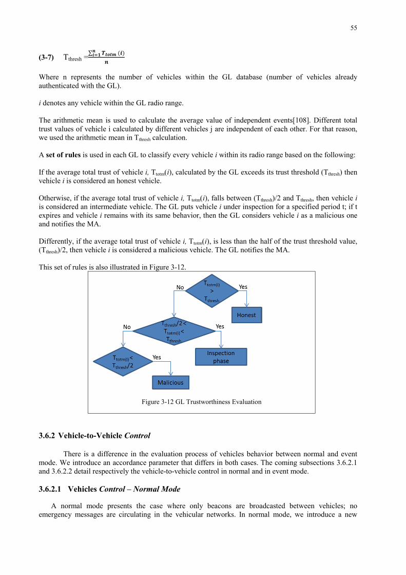
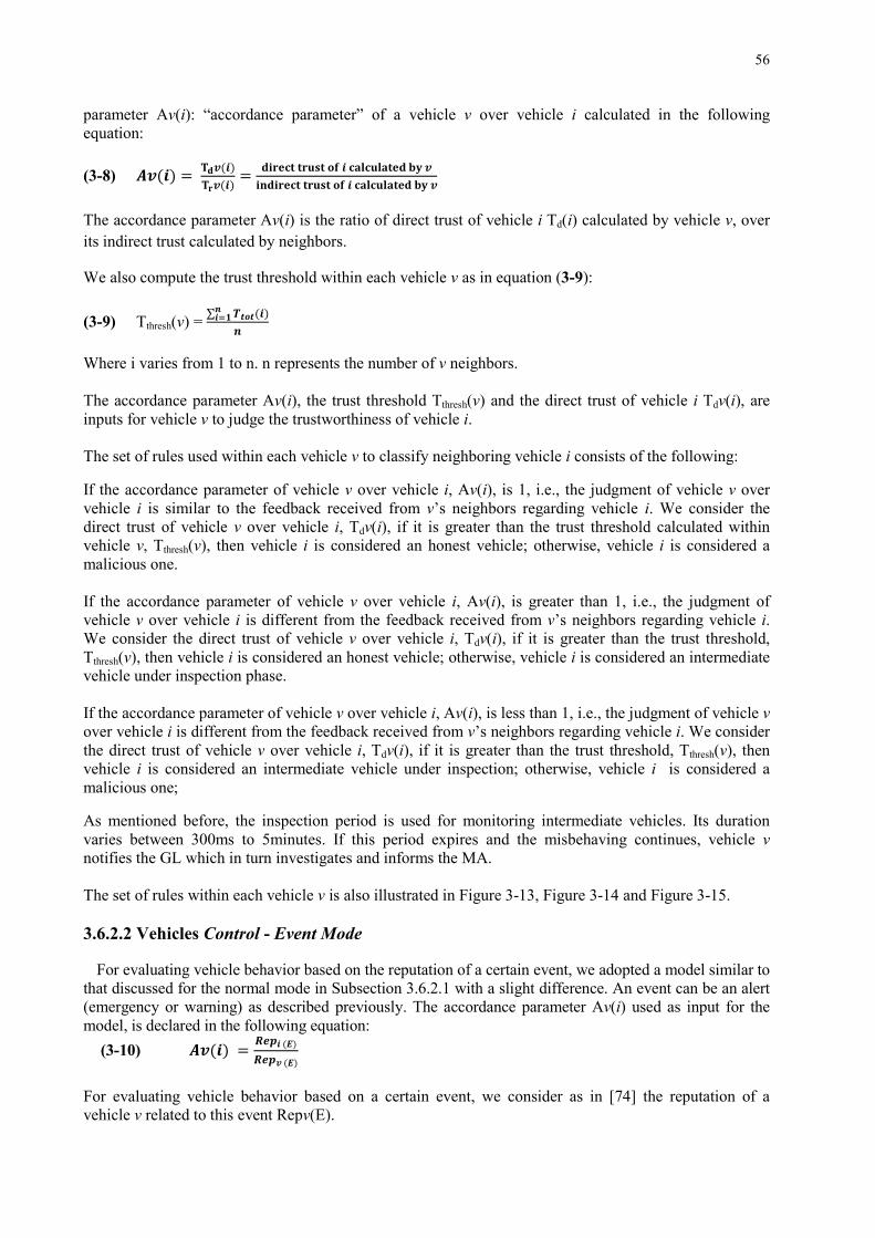
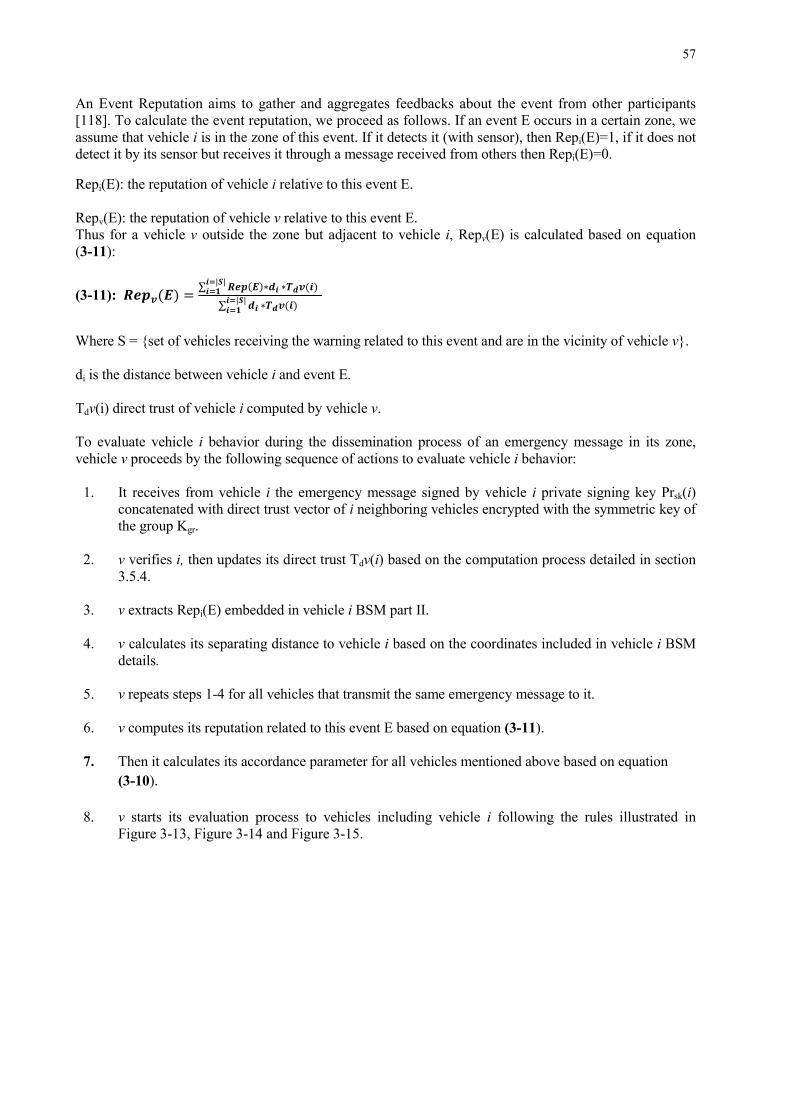
HAL Id: tel-01892393 https://tel.archives-ouvertes.fr/tel-01892393 Submitted on 10 Oct 2018 HAL is a multi-disciplinary open access archive for the deposit and dissemination of sci- entific research documents, whether they are pub- lished or not. The documents may come from teaching and research institutions in France or abroad, or from public or private research centers. L’archive ouverte pluridisciplinaire HAL, est destinée au dépôt et à la diffusion de documents scientifiques de niveau recherche, publiés ou non, émanant des établissements d’enseignement et de recherche français ou étrangers, des laboratoires publics ou privés. Trust management and security solutions for vehicular networks Hamssa Hasrouny To cite this version: Hamssa Hasrouny. Trust management and security solutions for vehicular networks. Networking and Internet Architecture [cs.NI]. Institut National des Télécommunications, 2018. English. NNT: 2018TELE0001. tel-01892393
Transcript
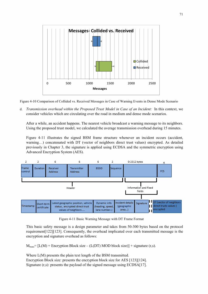
HAL Id: tel-01892393https://tel.archives-ouvertes.fr/tel-01892393
Submitted on 10 Oct 2018
HAL is a multi-disciplinary open accessarchive for the deposit and dissemination of sci-entific research documents, whether they are pub-lished or not. The documents may come fromteaching and research institutions in France orabroad, or from public or private research centers.
L’archive ouverte pluridisciplinaire HAL, estdestinée au dépôt et à la diffusion de documentsscientifiques de niveau recherche, publiés ou non,émanant des établissements d’enseignement et derecherche français ou étrangers, des laboratoirespublics ou privés.
Trust management and security solutions for vehicularnetworks
Hamssa Hasrouny
To cite this version:Hamssa Hasrouny. Trust management and security solutions for vehicular networks. Networkingand Internet Architecture [cs.NI]. Institut National des Télécommunications, 2018. English. �NNT :2018TELE0001�. �tel-01892393�
Kinda Khawam, Maître de conférences HDR, Université de Versailles
Saint Quentin
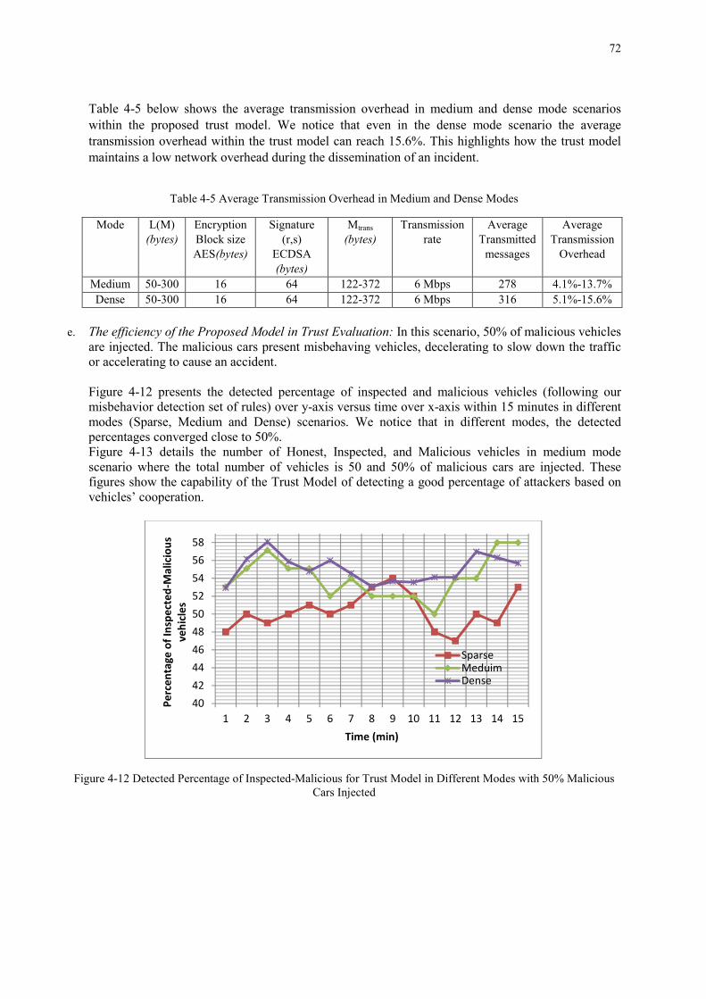
Riadh Dhaou, Maître de conférences HDR, ENSEEIHT de Toulouse
NNT : <2018TELE0001>
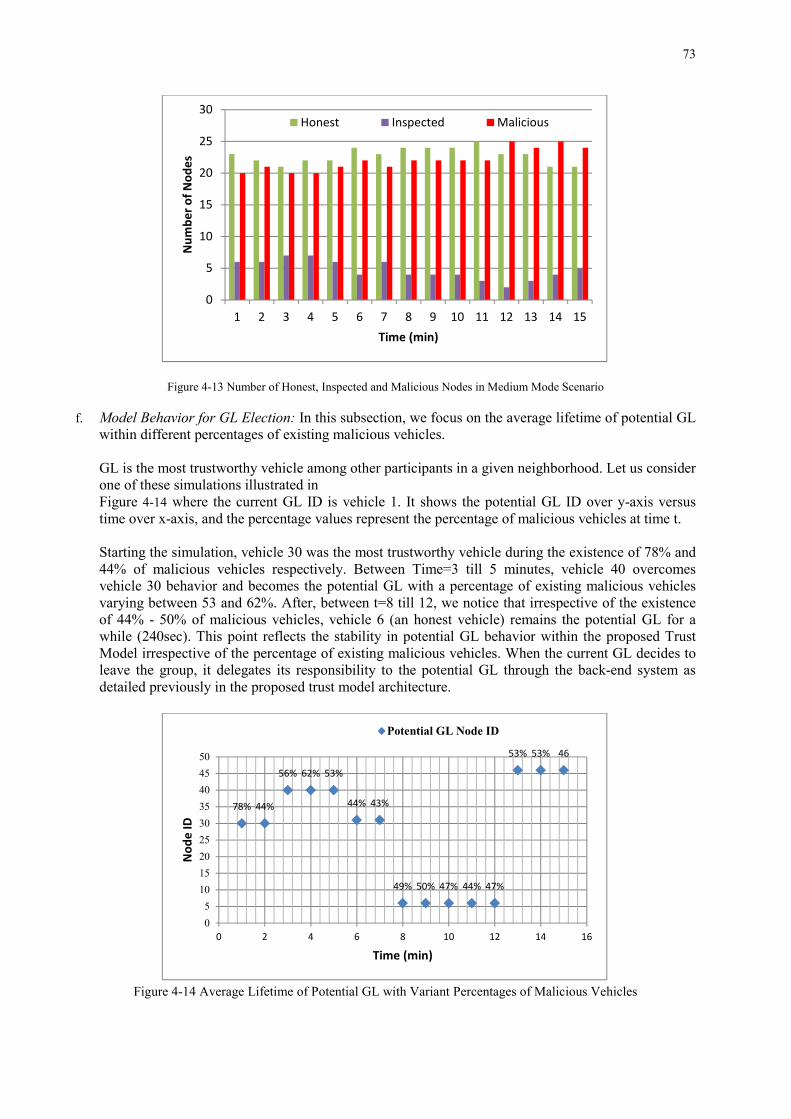
Declaration I declare that I wrote this thesis and that the work contained therein is my own, except where explicitly stated otherwise in the text.
Hamssa Hasrouny
Acknowledgments
First off, I would like to express my sincere gratitude and appreciation to my thesis advisors, Prof. Abed Ellatif Samhat, Prof. Anis Laouiti and Dr. Carole Bassil, for their invaluable guidance, constant encouragement, and endless patience during my Ph.D. study. Thanks to them, I had the opportunity to conduct and complete my thesis in Telecom SudParis. I will be forever honored and grateful for working with them. Without their help and advice, I would not have been able to write this thesis. They inspired me to do my best to accomplish my goals. They helped me to grow professionally, and I learned many skills from them that will be of most significant assistance in my future career. My gratitude extends to Prof. Steven Martin and Prof. Pascal Lorenz for their time in reviewing my manuscript and for their insightful comments. I would also like to thank Prof. Guy Pujolle, Dr. Kinda Khawam and Dr. Riadh Dhaou for accepting the invitation to participate in the defense. I would like to express my special thanks to Reverend Abbot Semaan Atallah and Reverend Abbot Daoud Reaidy for their support.
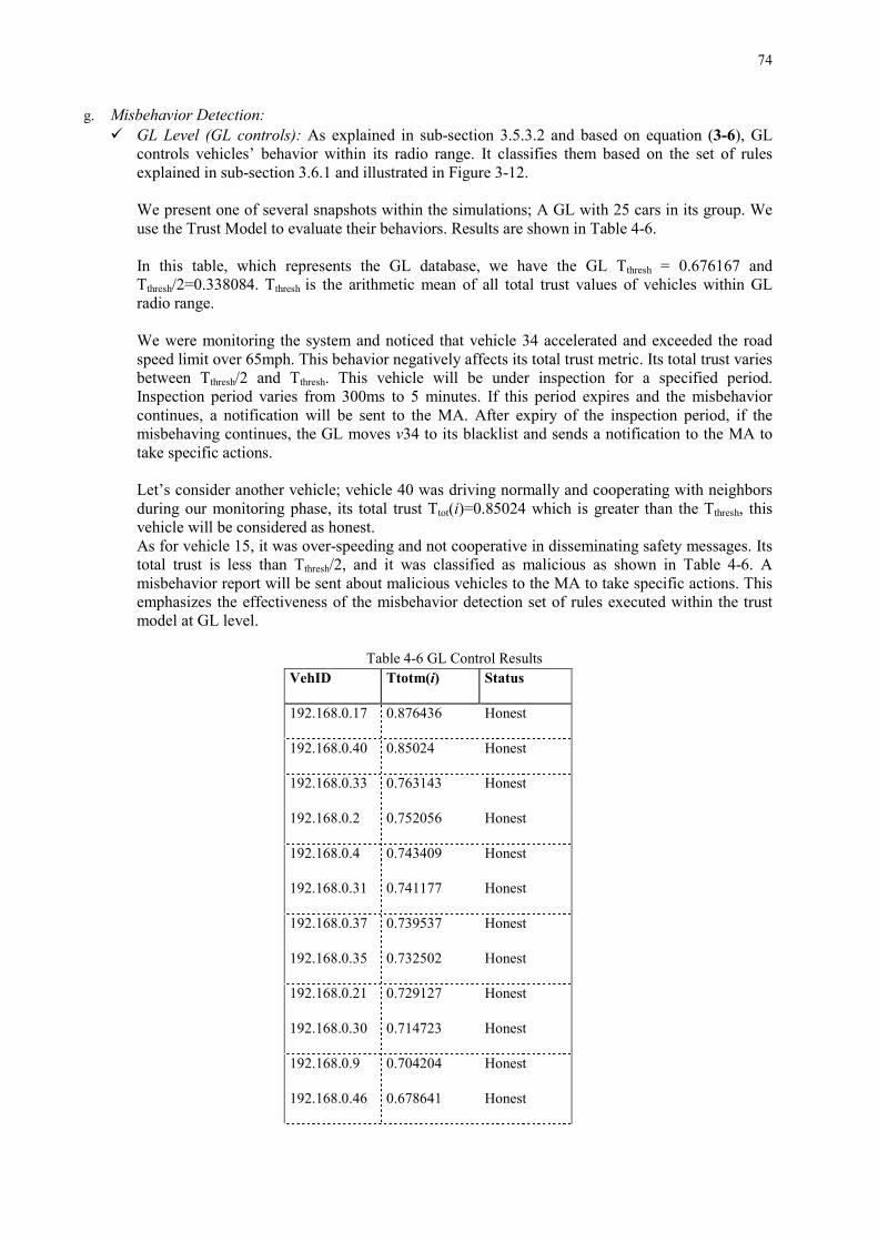
I would moreover like to thank my parents. They were always supporting me and encouraging me. My parents-in-law thank you for your continuous help.
To all the team at Telecom SudParis, faculty, staff and colleagues, thank you for everything. Your optimism, kindness, and perseverance made my Ph.D. experience unique and unforgettable.
This thesis is dedicated to you, Tony, my dearest husband, who has always been present at my side to support and encourage me ... and for you my little children, Marie-Sophie, Mario, and Lea who suffered a lot due to my occupations in this thesis. But you knew it; the most beautiful is coming for all of us! Thank you my little family. Thank You, God Almighty; without you, nothing of the above could have been achieved.
Summary The growing mobility of people using vehicles has a high cost regarding traffic congestion and
injured people every year. In this context, VANET (Vehicular Ad-hoc Networks) was identified as a key technology to increase safety, and provide critical safety information to road users. VANET is a special class of mobile ad-hoc network with specific authorities for registration and management, the Roadside Units (RSUs) and the On-Board Units (OBUs). RSUs are widespread on the roadside to fulfill specific services, and OBUs are installed in the vehicles moving freely on the road network and communicating with each other or with RSUs and specific authorities. Using Dedicated Short Range Communication (DSRC) in a single or multi-hop, the communication mode is either V2V (Vehicle-to-Vehicle), V2I (Vehicle-to-Infrastructure) or hybrid. Vehicles are capable of exchanging information by radio to improve road safety (alerts in case of accidents or case of abnormal slowdowns, collaborative driving..) or allow internet access for passengers (collaborative networks, infotainment, and management of free spaces in car parking..). Unfortunately, road safety messages exchanged between vehicles may be falsified or eliminated by malicious entities to cause accidents and endanger people’s life. This issue lets VANET become an emergent technology with promising future as well as significant challenges, especially in its security. In this thesis, we focus mainly on designing a security solution to ensure a secure V2V communication with confidence between the different participating vehicles in VANET. Hence, this solution can efficiently adapt to frequently changing of network topologies and resist to various known attacks. After analyzing the existing security architectures, infrastructure and solutions within the vehicular networks, we consider the trustworthiness problem in VANET, where vehicles need to communicate securely together and with the infrastructure. Nodes receiving data need to trust the sender because sometimes even authenticated nodes can produce malicious issues. We adopt a group-based model to evaluate the trustworthiness of participating vehicles in VANET because, in comparison with the Public Key Infrastructure (PKI) scheme, this avoids the generation of delays and reduces the communication with the infrastructure. We then develop a trust model to select the most trustworthy node in a given neighborhood as a group leader (GL) and to analyze the vehicles’ behavior within their groups while preserving the privacy of the participants and maintaining low network overhead. Centralized and distributed entities cooperate to perform this evaluation. We then propose a hierarchical and modular framework for misbehavior detection. Misbehavior detection results from the cooperation of the vehicles, Group Leaders and at the back-end system (infrastructure) to filter out the malicious behavior and then notify the Misbehavior Authority to take specific actions. We evaluate the performance of the proposed trust model using the network and vehicular traffic simulator GrooveNet. The simulation results show its ability to detect the malicious vehicles and electing the most trustworthy as potential GLs in dense, medium and sparse modes scenarios while maintaining low network overhead. Furthermore, we consider a new risk analysis methodology based on SecRAM [84] and ETSI TVRA (Threat, Vulnerability, and Risk Analysis) [25] to analyze the security risks that threaten this model and lead to an unstable environment. We demonstrate that the majority of the threats are mitigated using security controls (countermeasures) taken into consideration within the proposed Trust Model. Finally, we investigate the revocation process. Using our proposed misbehavior detection system within the proposed Trust Model, we develop a framework for the revocation schema. It is based on the assumption of a hierarchical grouping within the network based on vehicles, GLs, RSUs and the infrastructure. Hence, the revocation is done periodically through the Certificate Revocation List (CRL) which specifies all revoked vehicles. We propose an improvement for the CRL dissemination which consists of disseminating geographical CRL via GLs to the groups that contain the malicious activity only. This solution reduces the CRL size and saves the network performance. We define the update rate and the incentive for the CRL dissemination. Keywords: VANET, Security, Grouping, Multi-hop Communication, Trust Management, Risk Analysis, Misbehavior Detection, Revocation Process.
Résumé
La mobilité croissante des personnes conduisant des voitures cause des congestions routières et résulte en un nombre annuel élevé de blessés dû aux accidents de la route. Dans ce contexte, VANET (Réseau Ad-Hoc Véhiculaire) a été identifié comme une technologie clé pour assurer la sécurité routière en fournissant des informations de sécurité critiques aux usagers de la route. VANET est une classe spéciale des réseaux mobiles avec des autorités spécifiques pour l'enregistrement et la gestion, des équipements d’infrastructure routière (RSUs) et des équipements embarqués (OBUs). Les RSUs sont implantés sur les bords de la route pour répondre à des services spécifiques et les OBUs sont installés dans les véhicules qui circulent librement sur le réseau routier et communiquent les uns avec les autres ou avec des équipements d’infrastructure routières (RSUs) et autres entités bien spécifiques. En se basant sur le standard de communication à courte distance dédiée (DSRC) pour assurer la communication entre les voitures en un seul ou plusieurs sauts, le mode de communication est classé en V2V (véhicule à véhicule), V2I (véhicule à infrastructure) ou hybride. Les véhicules sont capables d'échanger des informations par radio pour améliorer la sécurité routière (les alertes en cas d'accident ou en cas de ralentissements anormaux, la conduite collaborative ...) ou permettre l'accès Internet aux passagers (les réseaux collaboratifs, info-divertissement et la gestion des espaces libres dans les parkings..). Malheureusement, les messages de sécurité routière échangés entre les véhicules peuvent être falsifiés ou éliminés par des entités malveillantes afin de causer des accidents et de mettre en danger la vie des personnes. Cela permet à VANET qui est une technologie émergente d’avoir un avenir prometteur malgré ses grands défis, en particulier dans la sécurité des communications. Dans cette thèse, nous nous concentrons particulièrement sur la conception d'une solution de sécurité pour assurer une communication V2V sécurisée tout en instaurant la confiance entre les différents véhicules participants dans un réseau VANET. Par conséquent, cette solution peut s'adapter efficacement aux changements fréquents de topologies de réseau et résister à diverses attaques connues. Après avoir analysé les architectures de sécurité, les infrastructures et les solutions existantes dans les réseaux véhiculaires, nous considérons le problème de confiance dans les réseaux VANETs, où un certain nombre de véhicules doivent communiquer ensemble en toute sécurité ainsi qu’avec l'infrastructure. Les nœuds recevant des données doivent faire confiance à l'expéditeur car, parfois, même les nœuds authentifiés peuvent causer des problèmes malveillants. Nous adoptons un modèle de groupe pour évaluer la fiabilité des véhicules participants dans VANETs. En comparaison avec l’infrastructure à clé publique (PKI) et en l'absence de groupement de véhicules, cela évite la génération de retards dus à la vérification du certificat ou pour authentifier l'expéditeur. Nous développons ensuite un modèle de confiance pour sélectionner le nœud le plus fiable en tant que chef de groupe (GL) et pour analyser le comportement des véhicules au sein de leurs groupes tout en préservant la confidentialité des participants et en maintenant un faible surcoût réseau. Les entités centralisées et distribuées coopèrent ensemble pour effectuer cette évaluation. Nous proposons ensuite un cadre hiérarchique et modulaire pour la détection de comportement. La détection de comportement indésirable des véhicules résulte de la coopération des véhicules, des chefs de groupe et de l’infrastructure afin de filtrer les comportements malveillants et d'informer ensuite l'autorité de comportement pour prendre des mesures spécifiques. Nous évaluons la performance du modèle de confiance proposé en utilisant le réseau et le simulateur de déplacement des véhicules GrooveNet. Les résultats de la simulation montrent sa capacité à détecter les véhicules malveillants et à choisir les GLs les plus fiables dans des scénarios avec un trafic routier dense, moyen et clairsemé, tout en maintenant un faible niveau de surcharge réseau. De plus, nous considérons une nouvelle méthodologie d'analyse des risques basée sur SecRAM [84] et ETSI TVRA (analyse des menaces, des vulnérabilités et des risques) [25] pour analyser les risques de sécurité qui menacent ce modèle et conduisent à un environnement instable. Nous démontrons que la majorité des menaces sont atténuées en utilisant les contrôles de sécurité (contre-mesures) pris en compte dans le modèle de confiance (Trust Model) proposé. Enfin, nous étudions le processus de révocation. En utilisant notre système de détection de comportement indésirable présenté dans le modèle de confiance proposé, nous développons un cadre pour le schéma de révocation. Il repose sur l'hypothèse d'une structure hiérarchique de regroupement au sein du réseau et qui est basée sur les véhicules, les GLs, les RSUs et l'infrastructure. Par conséquent, la révocation est effectuée périodiquement via la liste de révocation de certificats (CRL, Certificate Revocation List) qui
spécifie tous les véhicules révoqués. Nous proposons une amélioration pour la diffusion des CRLs qui consiste à diffuser des CRL géographiques via des GLs aux groupes qui ne contiennent que l'activité malveillante. Cela réduit la taille de la liste de révocation de certificats et sauvegarde les performances du réseau. Nous définissons le taux de mise à jour et l'incitation à la diffusion des CRLs. Mots-clés: VANET, Sécurité, Groupes, Communication multi-sauts, Gestion de la confiance, Analyse des risques, Détection de mauvaise conduite, Processus de révocation.
•
•
•
•
•
•
•
Contents
Summary ....................................................................................................................................... iv
Résumé ........................................................................................................................................... v
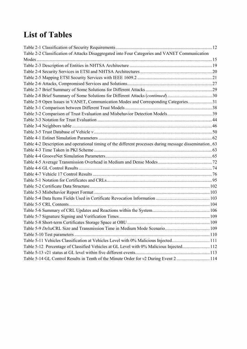
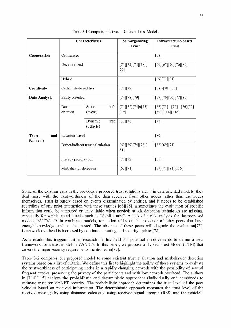
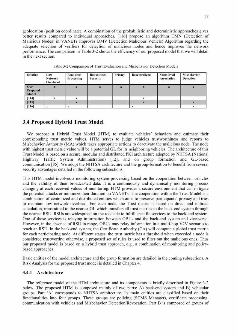
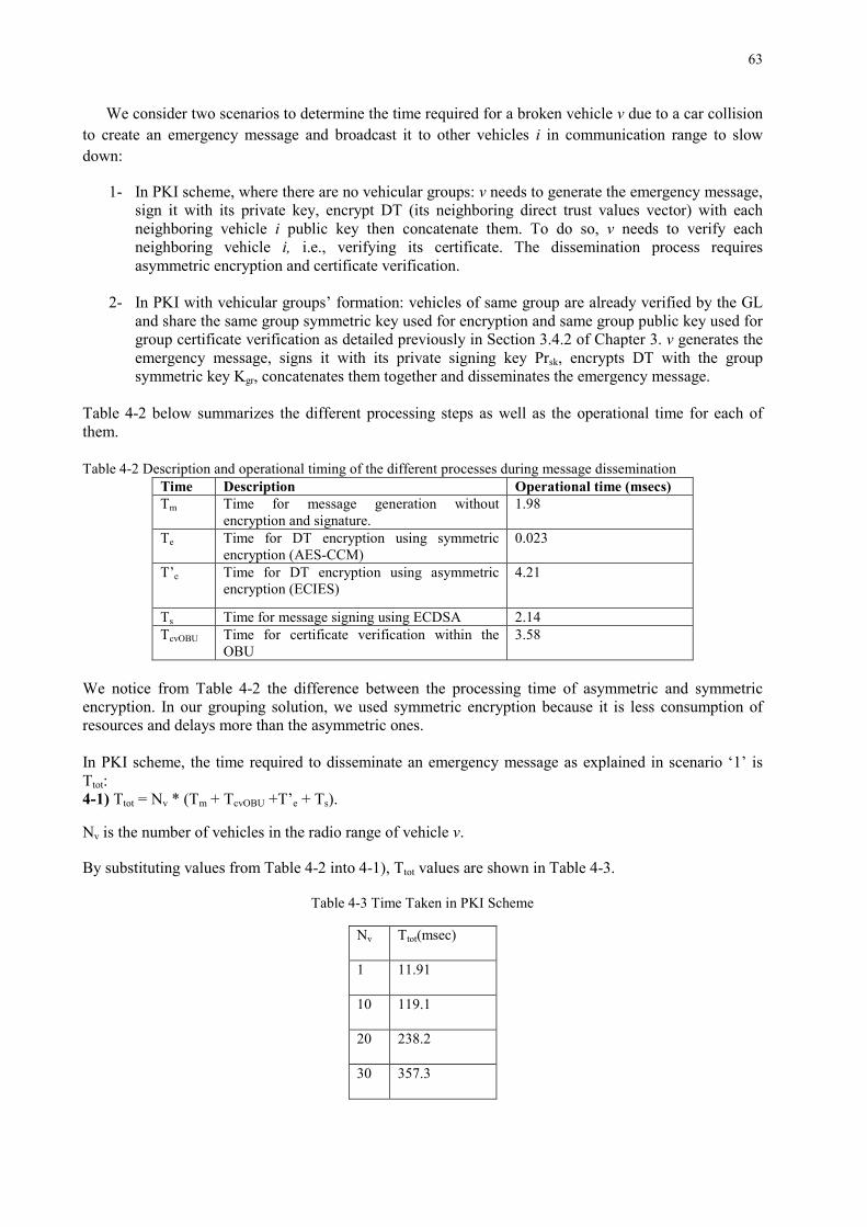
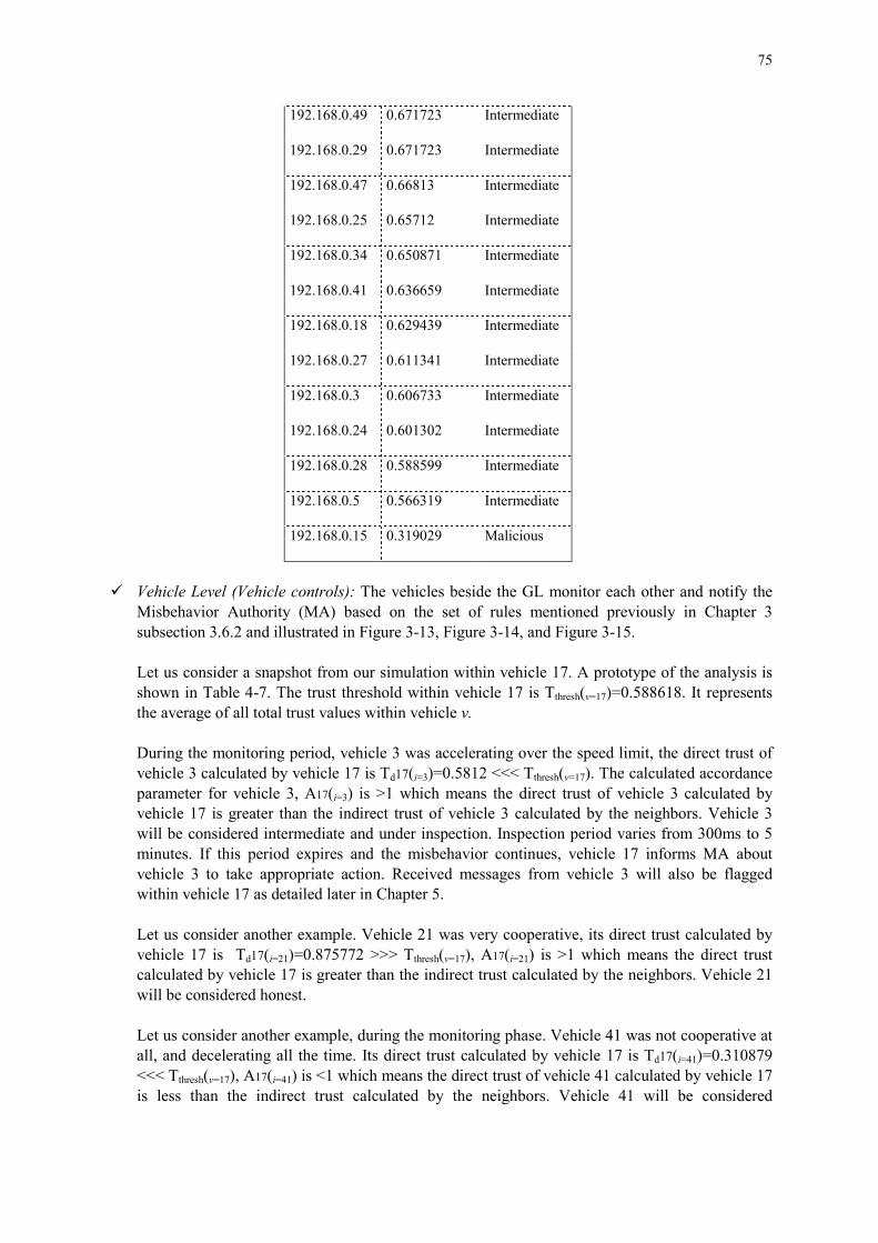
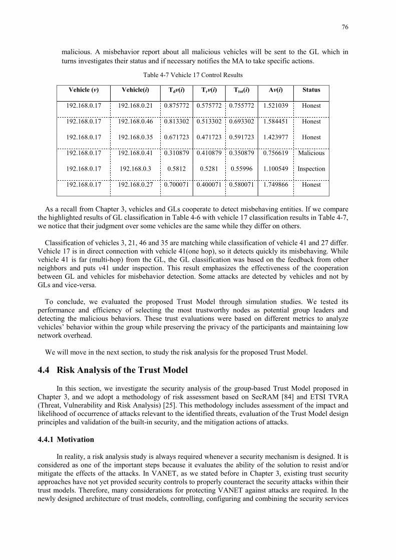
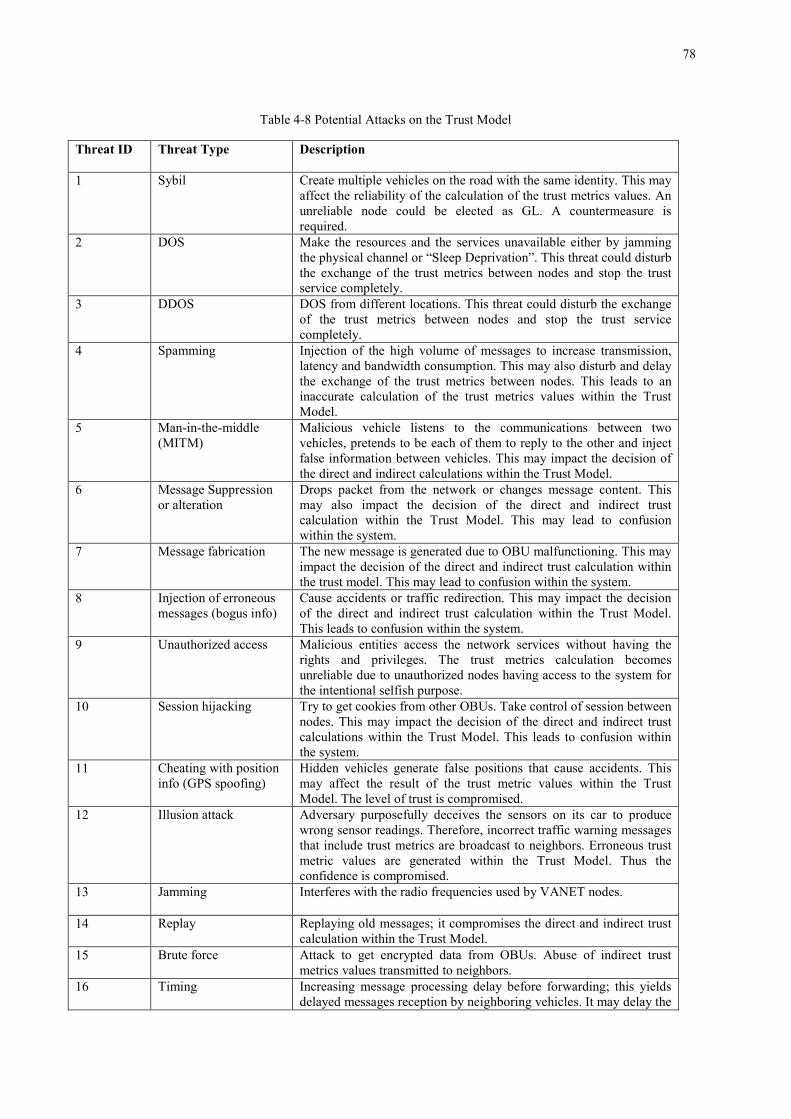
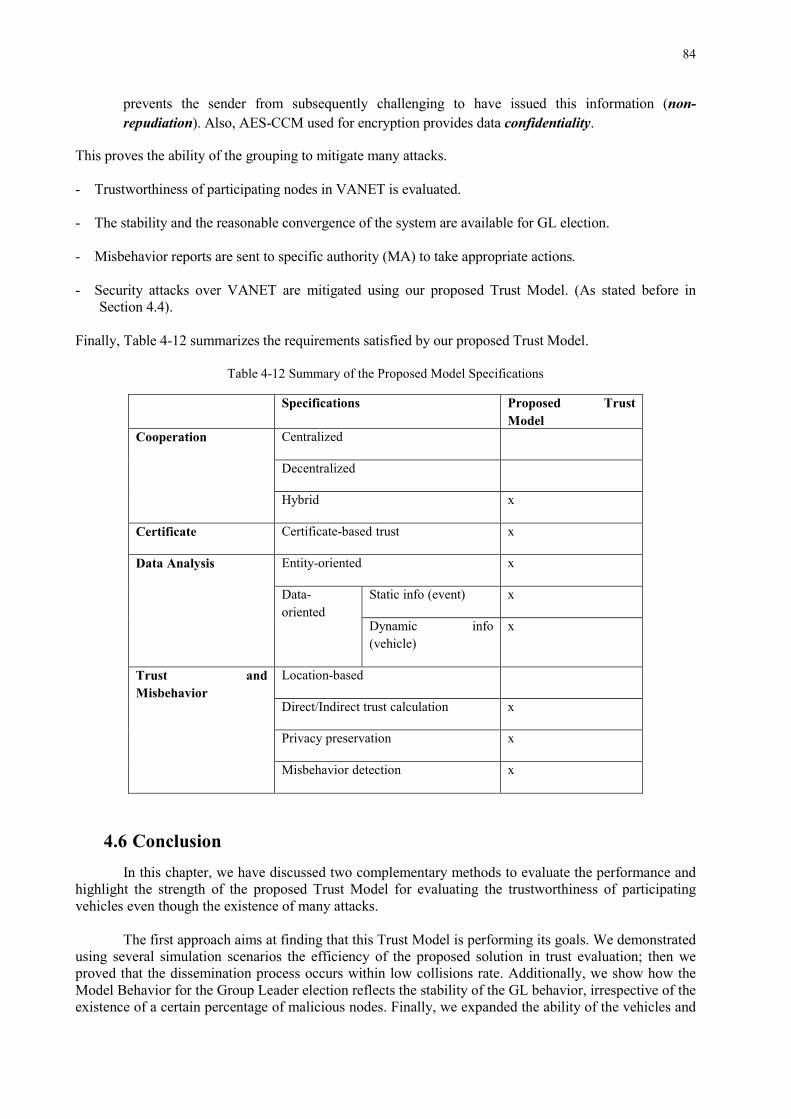
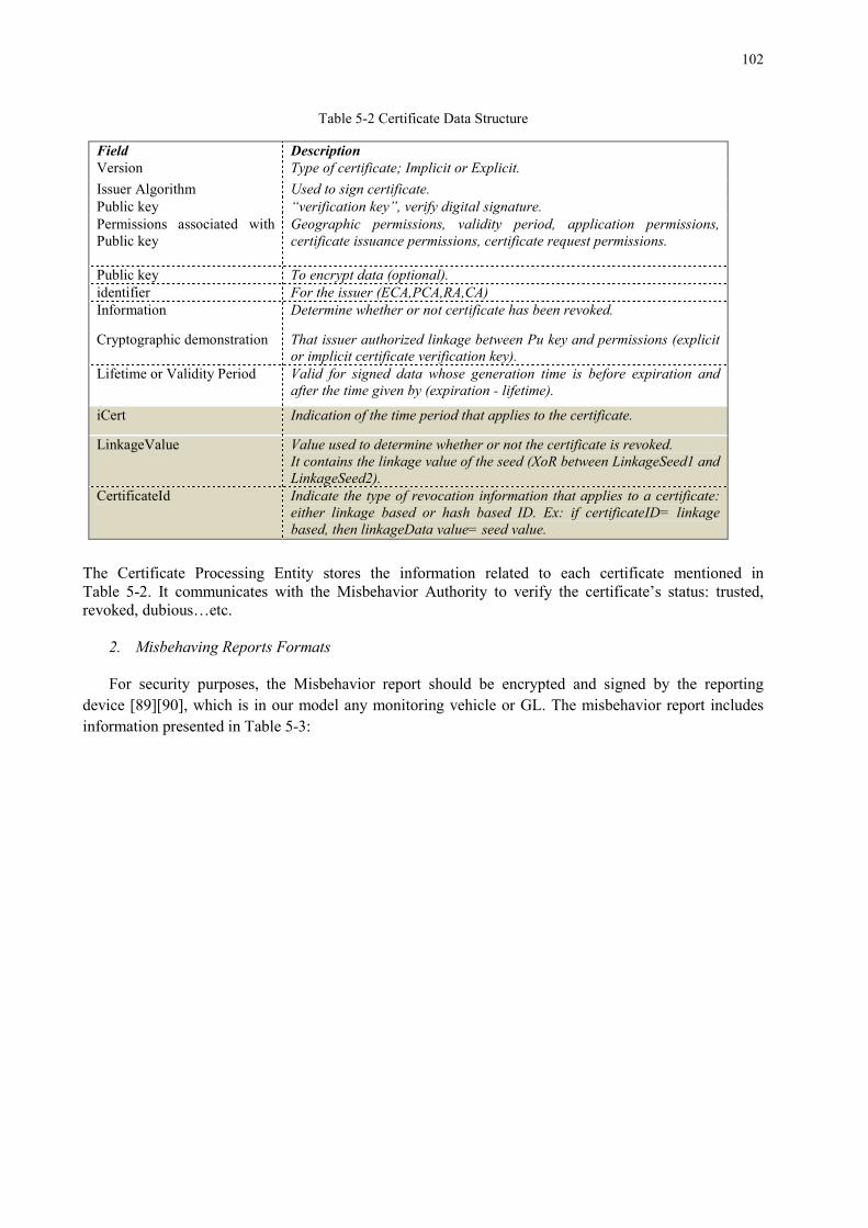
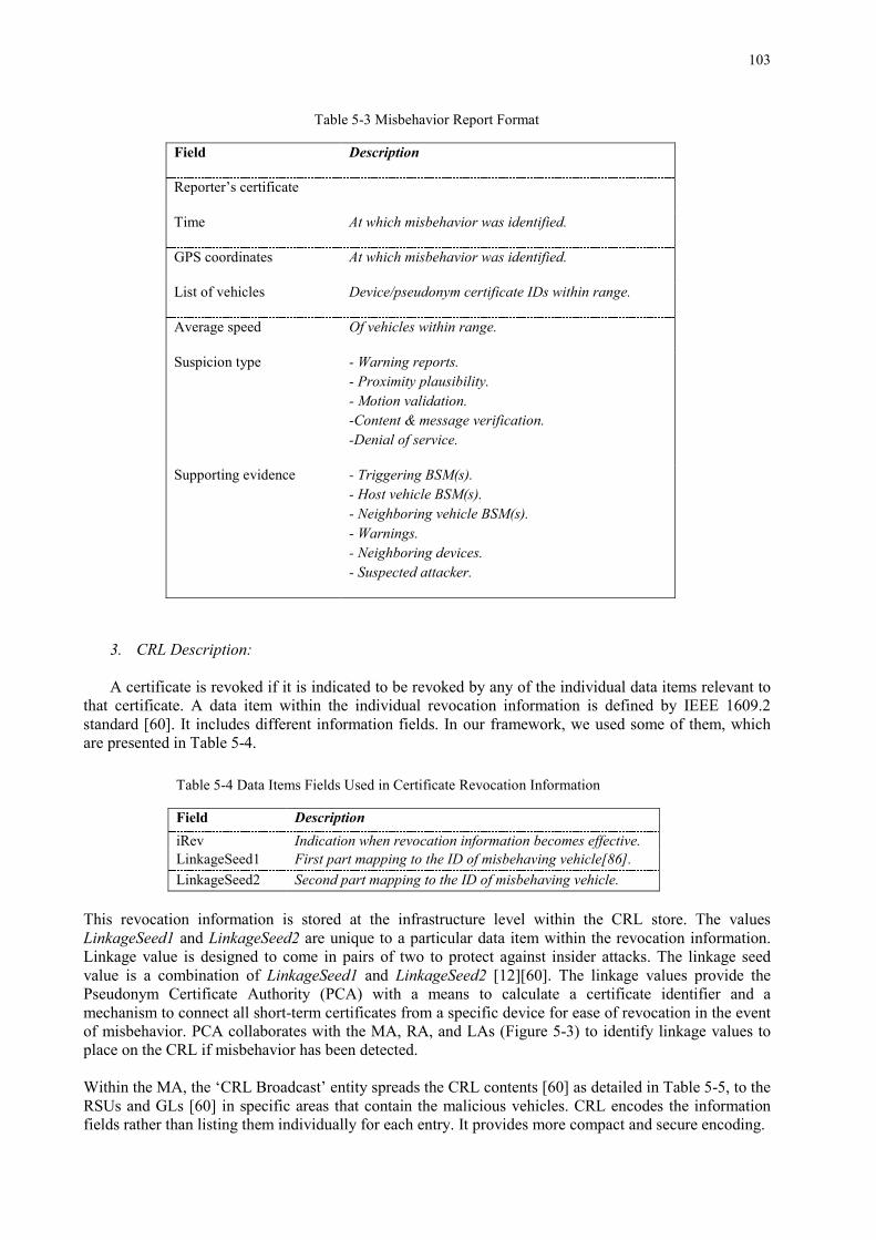
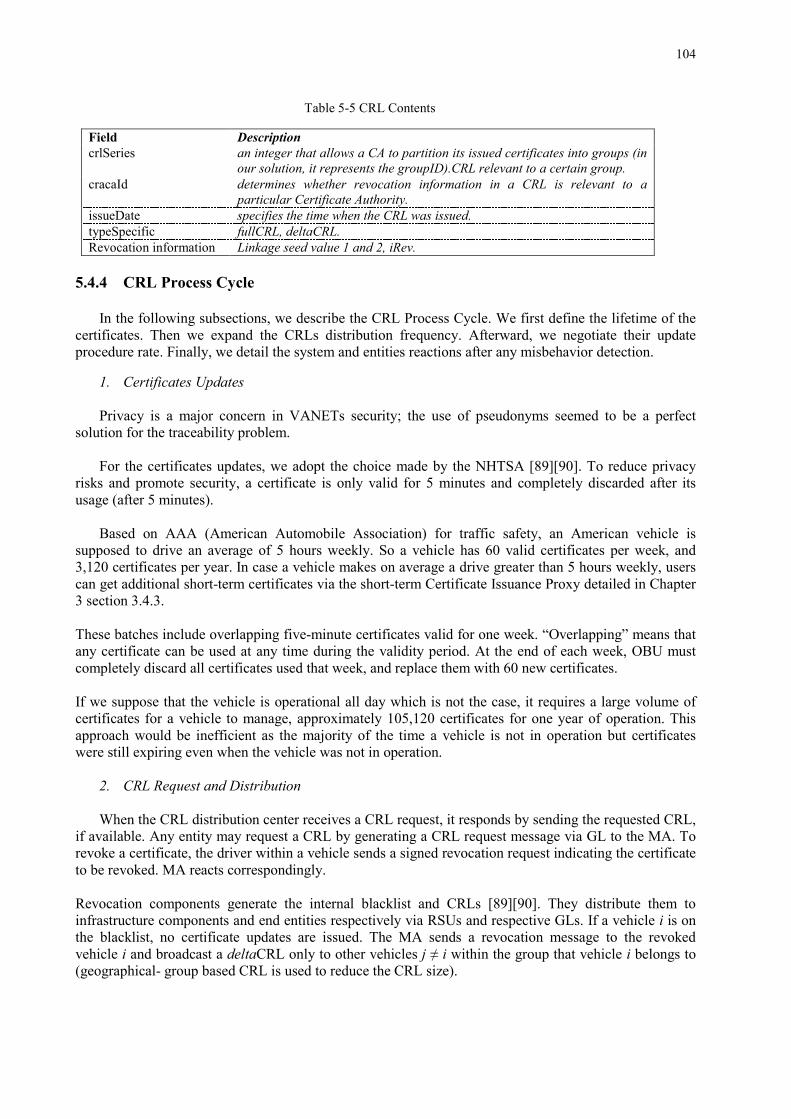
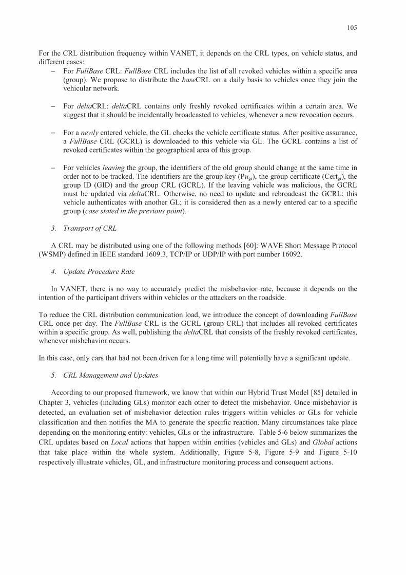
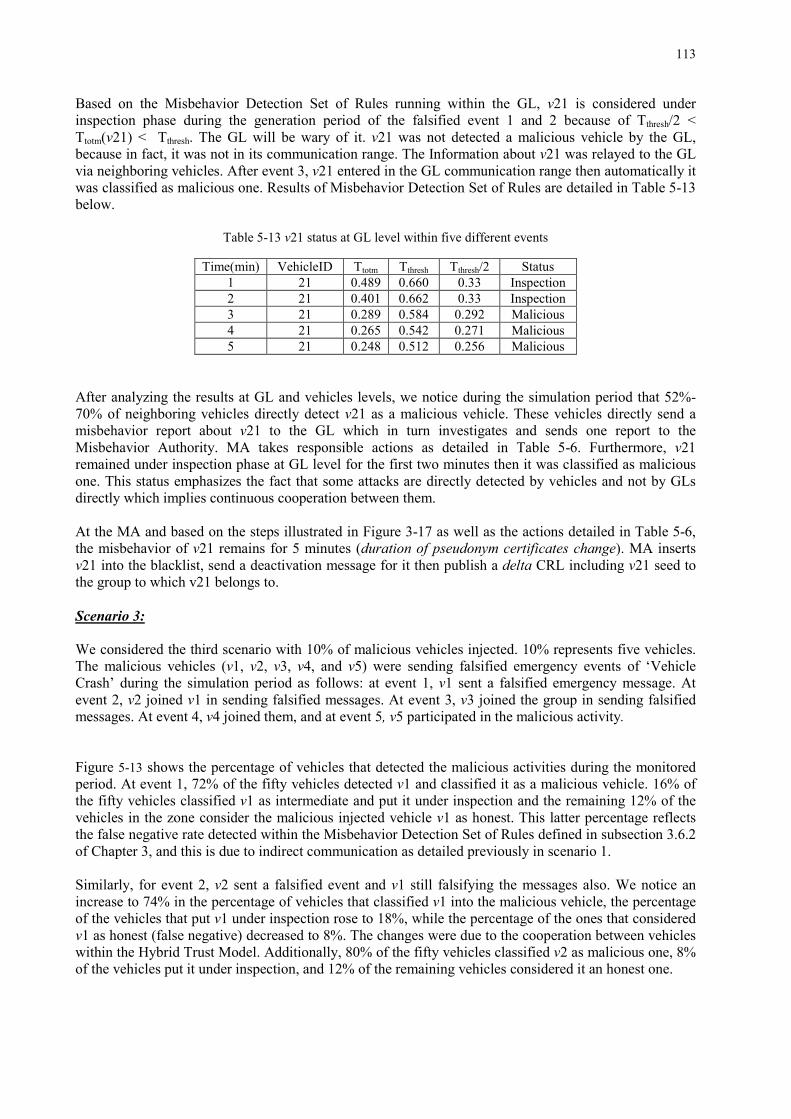
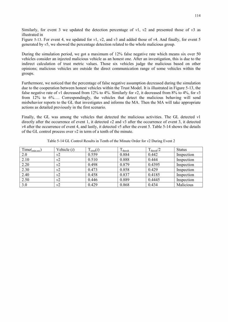
List of Tables Table 2-1 Classification of Security Requirements .................................................................................... 12 Table 2-2 Classification of Attacks Disaggregated into Four Categories and VANET Communication Modes ......................................................................................................................................................... 15 Table 2-3 Description of Entities in NHTSA Architecture ........................................................................ 19 Table 2-4 Security Services in ETSI and NHTSA Architectures ............................................................... 20 Table 2-5 Mapping ETSI Security Services with IEEE 1609.2 ................................................................. 21 Table 2-6 Attacks, Compromised Services and Solutions.......................................................................... 27 Table 2-7 Brief Summary of Some Solutions for Different Attacks .......................................................... 29 Table 2-8 Brief Summary of Some Solutions for Different Attacks (continued) ....................................... 30 Table 2-9 Open Issues in VANET, Communication Modes and Corresponding Categories. .................... 31 Table 3-1 Comparison between Different Trust Models ............................................................................ 38 Table 3-2 Comparison of Trust Evaluation and Misbehavior Detection Models ....................................... 39 Table 3-3 Notation for Trust Evaluation .................................................................................................... 44 Table 3-4 Neighbors table .......................................................................................................................... 46 Table 3-5 Trust Database of Vehicle v ....................................................................................................... 50 Table 4-1 Estinet Simulation Parameters ................................................................................................... 62 Table 4-2 Description and operational timing of the different processes during message dissemination .. 63 Table 4-3 Time Taken in PKI Scheme ....................................................................................................... 63 Table 4-4 GrooveNet Simulation Parameters ............................................................................................. 65 Table 4-5 Average Transmission Overhead in Medium and Dense Modes ............................................... 72 Table 4-6 GL Control Results .................................................................................................................... 74 Table 4-7 Vehicle 17 Control Results ........................................................................................................ 76 Table 5-1 Notation for Certificates and CRLs ............................................................................................ 95 Table 5-2 Certificate Data Structure ......................................................................................................... 102 Table 5-3 Misbehavior Report Format ..................................................................................................... 103 Table 5-4 Data Items Fields Used in Certificate Revocation Information ............................................... 103 Table 5-5 CRL Contents ........................................................................................................................... 104 Table 5-6 Summary of CRL Updates and Reactions within the System .................................................. 106 Table 5-7 Signature Signing and Verification Times ............................................................................... 109 Table 5-8 Short-term Certificates Storage Space at OBU ........................................................................ 109 Table 5-9 DeltaCRL Size and Transmission Time in Medium Mode Scenario ....................................... 109 Table 5-10 Test parameters ...................................................................................................................... 110 Table 5-11 Vehicles Classification at Vehicles Level with 0% Malicious Injected ................................. 111 Table 5-12 Percentage of Classified Vehicles at GL Level with 0% Malicious Injected ........................ 112 Table 5-13 v21 status at GL level within five different events ................................................................. 113 Table 5-14 GL Control Results in Tenth of the Minute Order for v2 During Event 2 ............................. 114
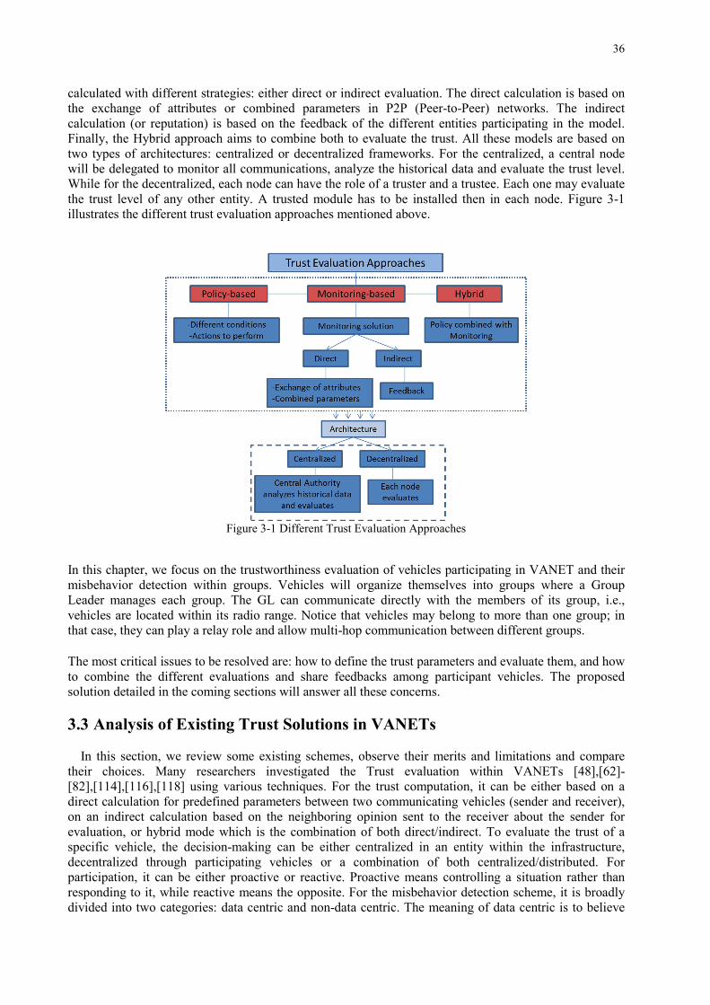
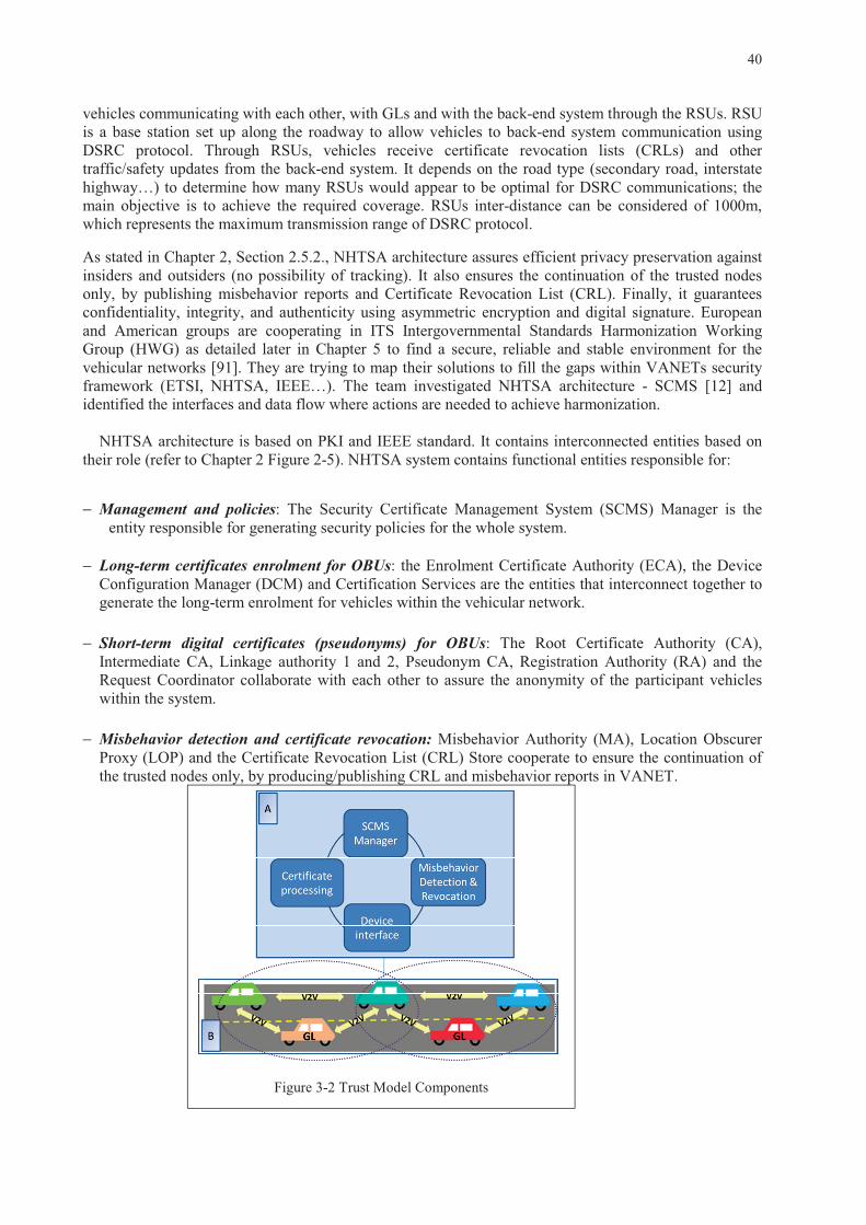
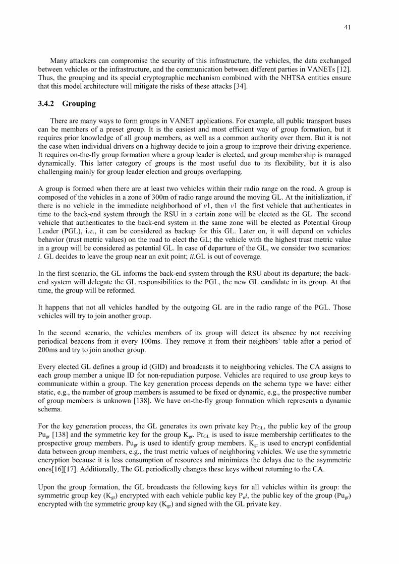
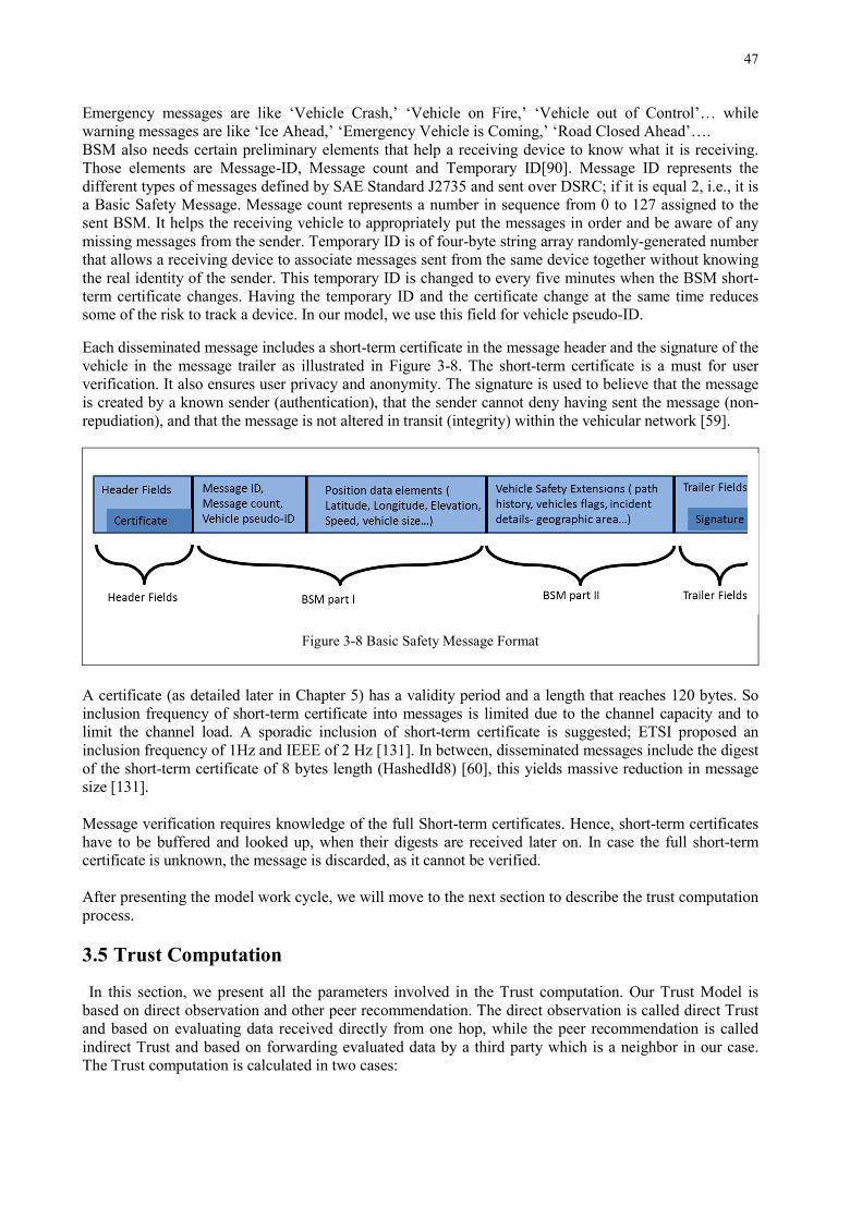
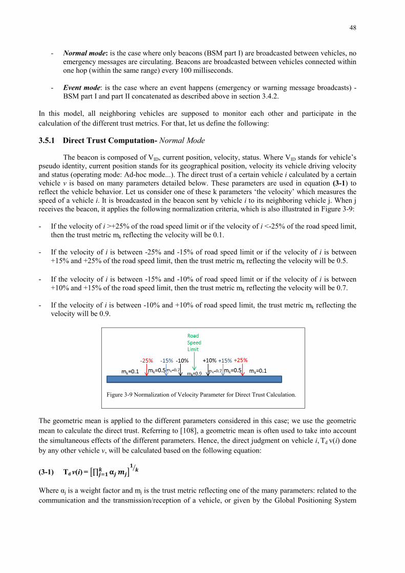
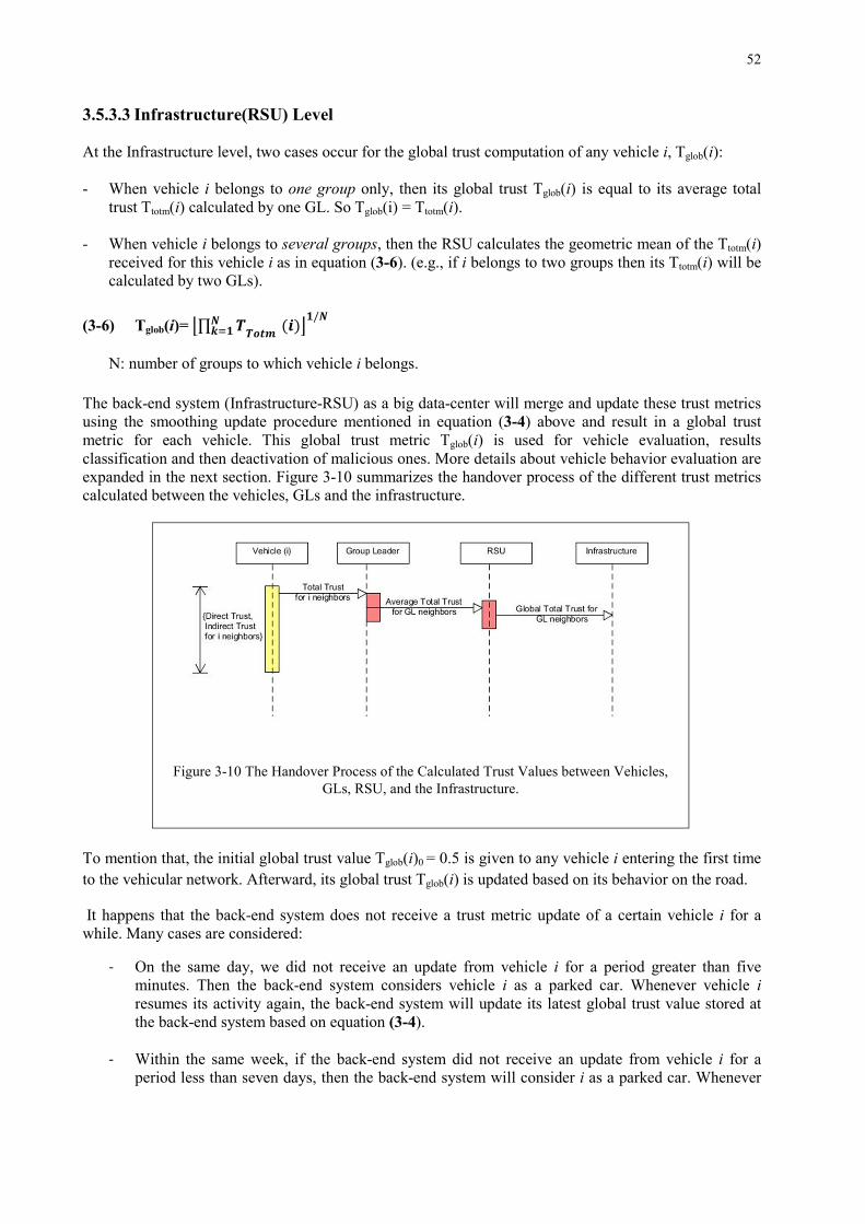
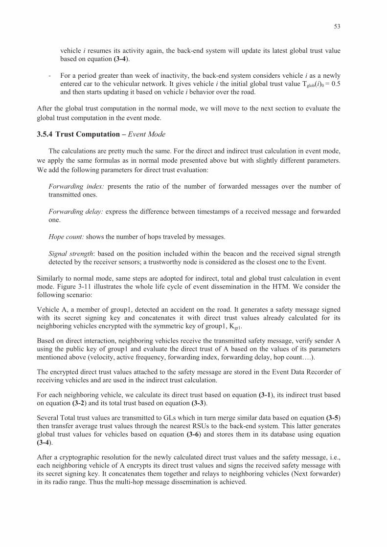
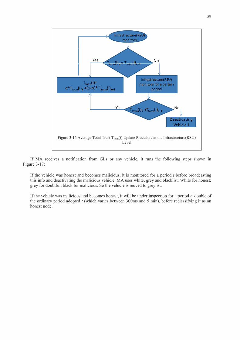
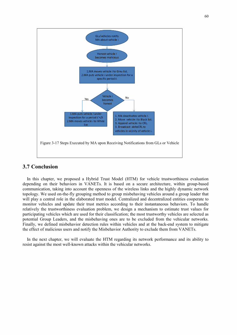
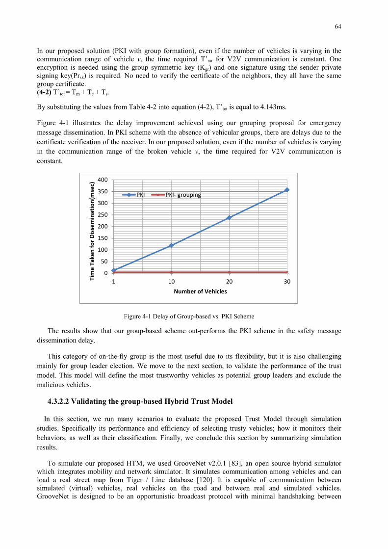
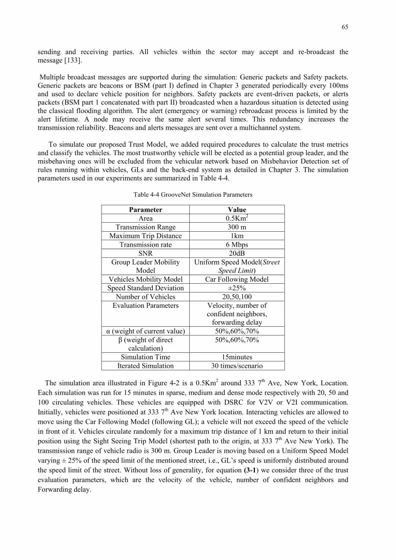
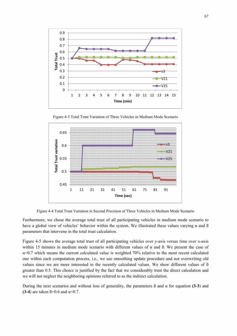
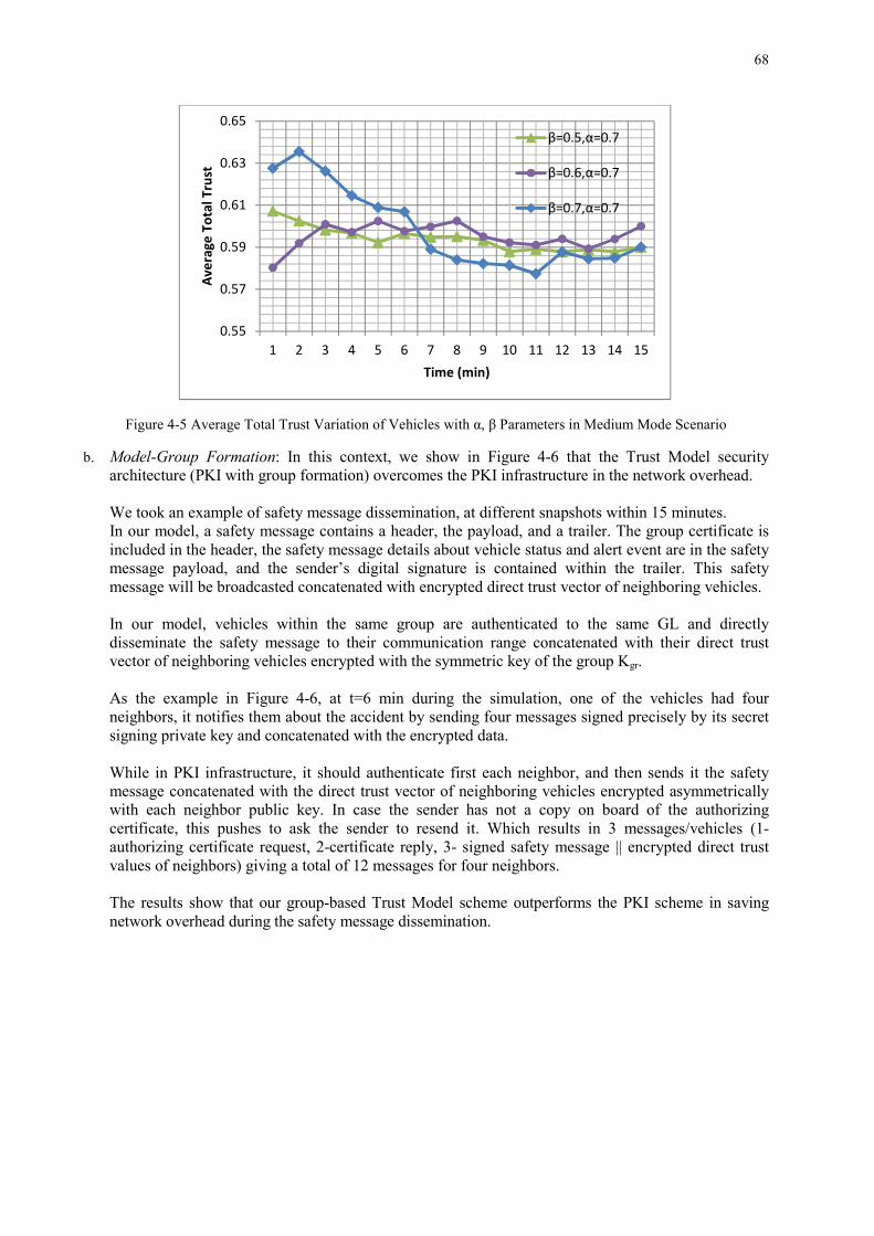
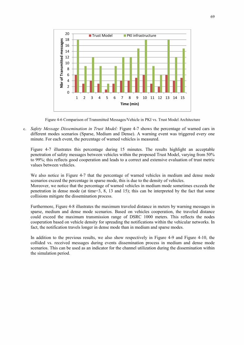
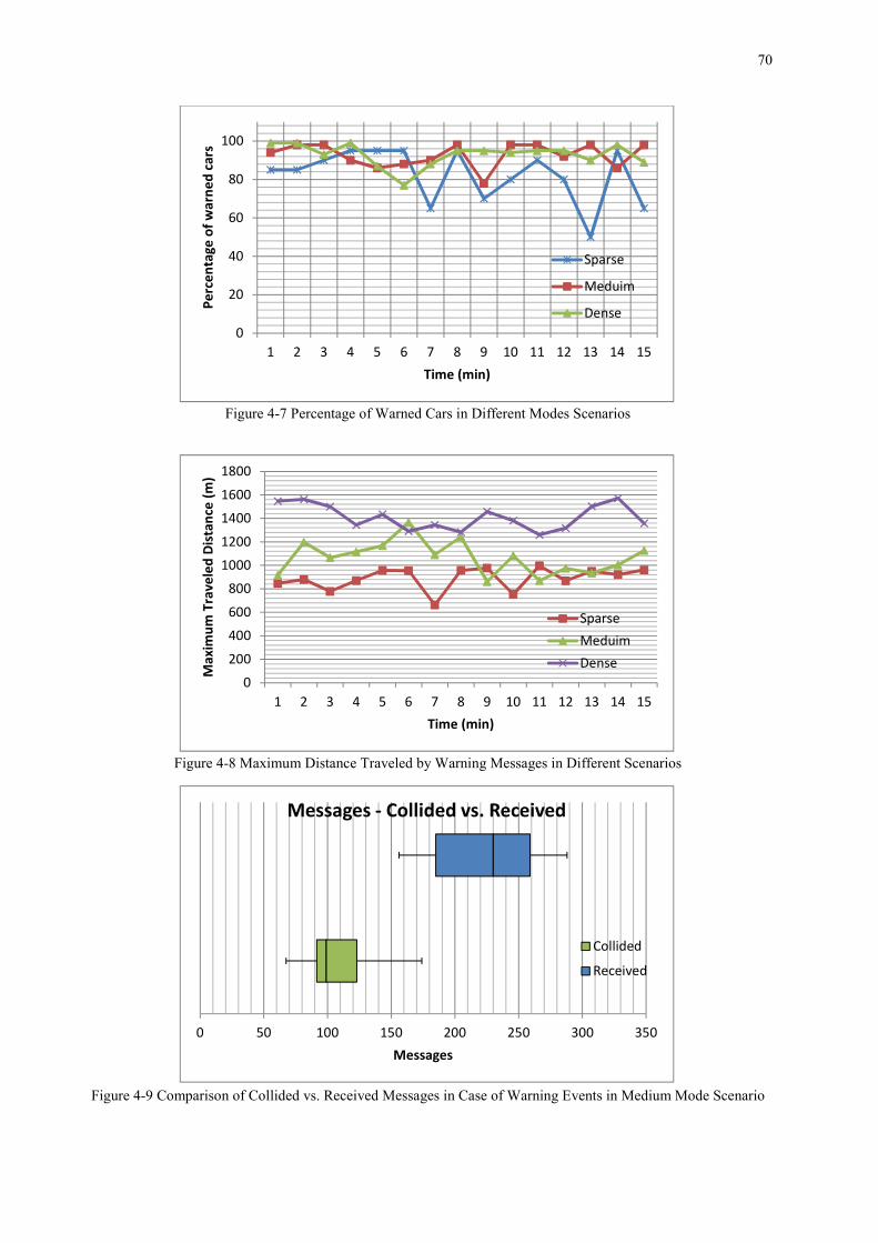
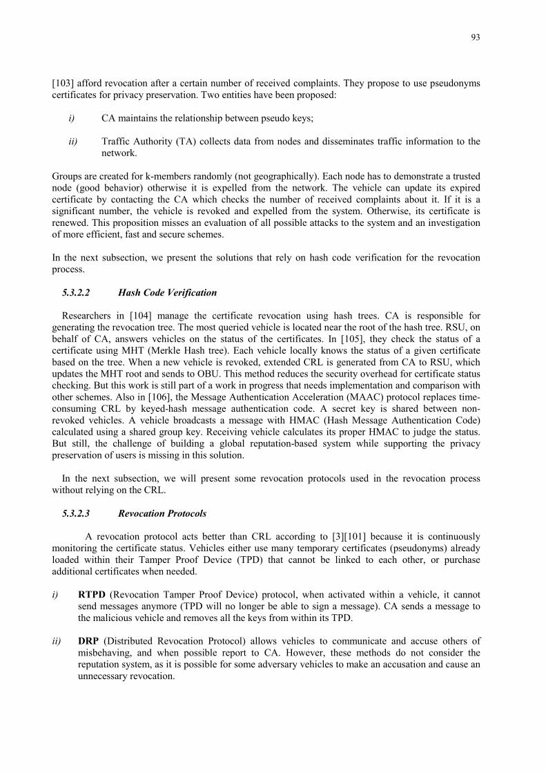
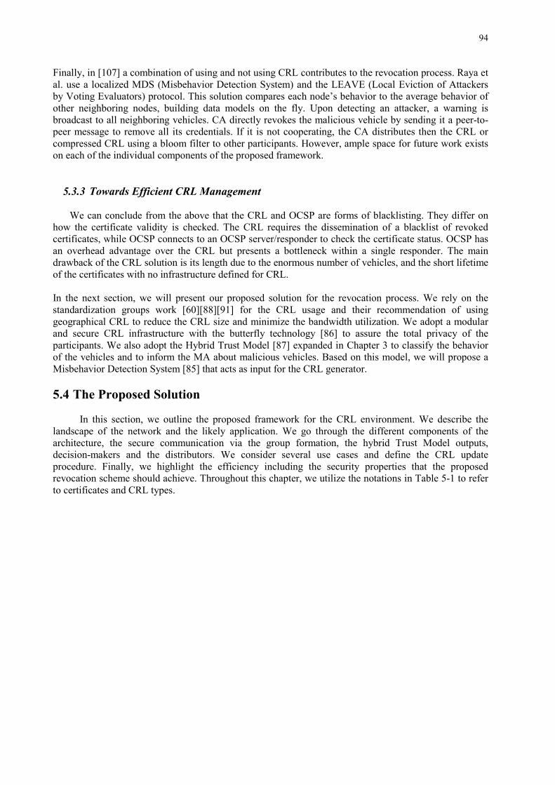
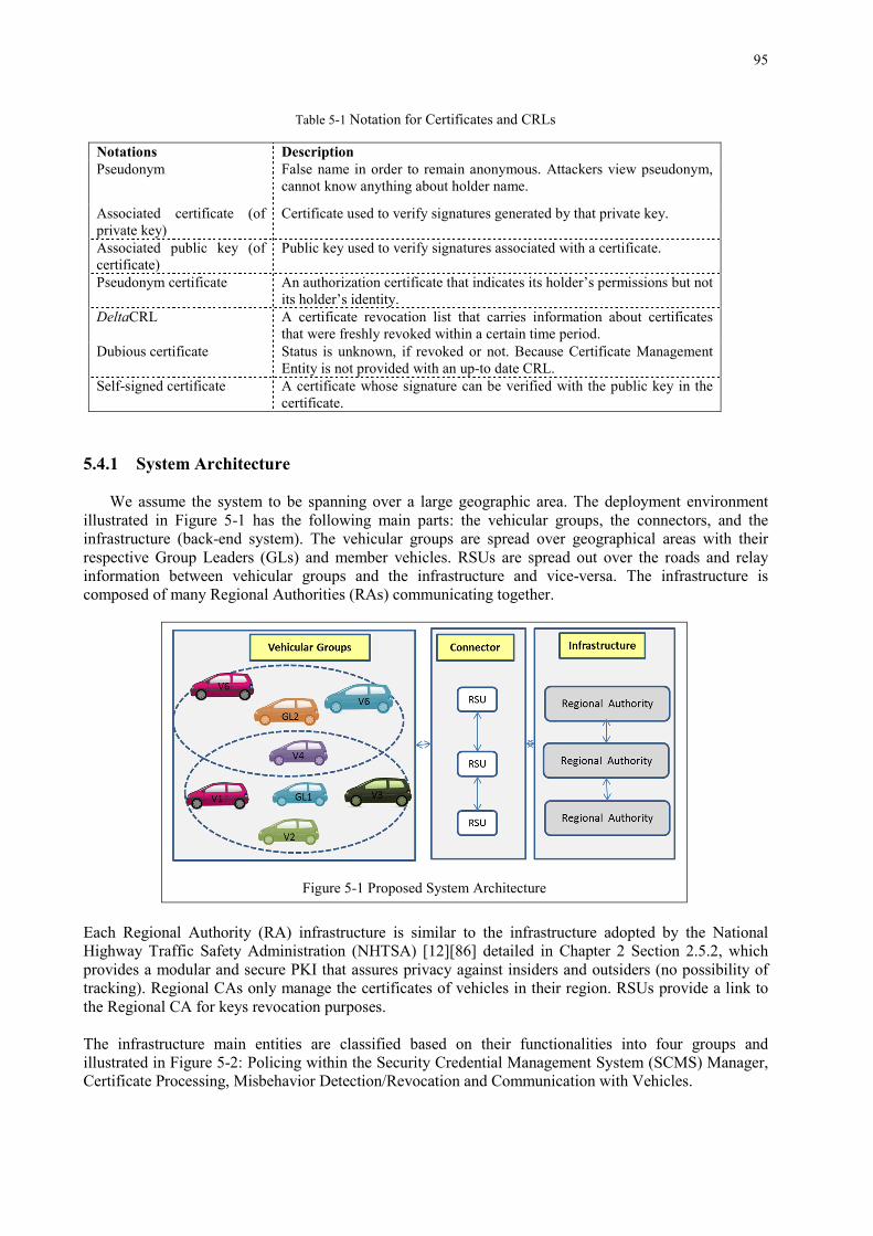
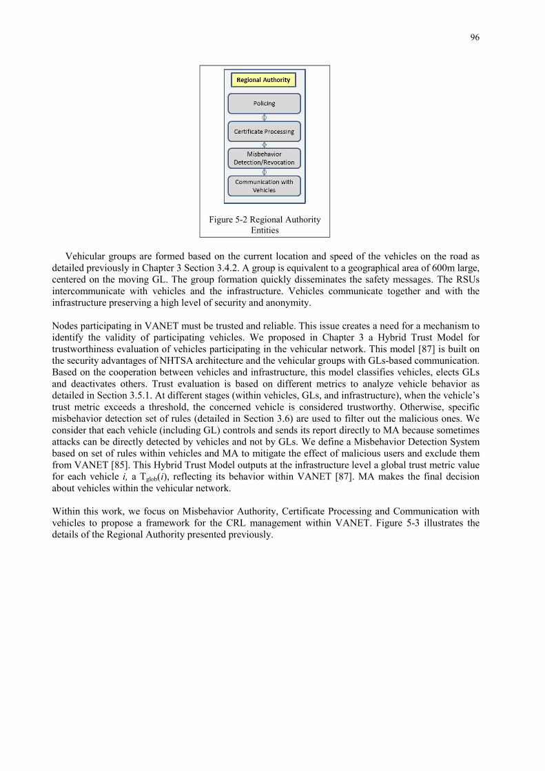
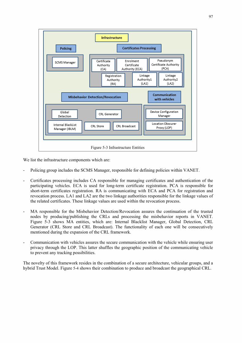
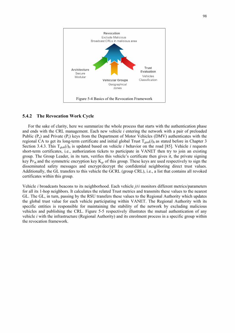
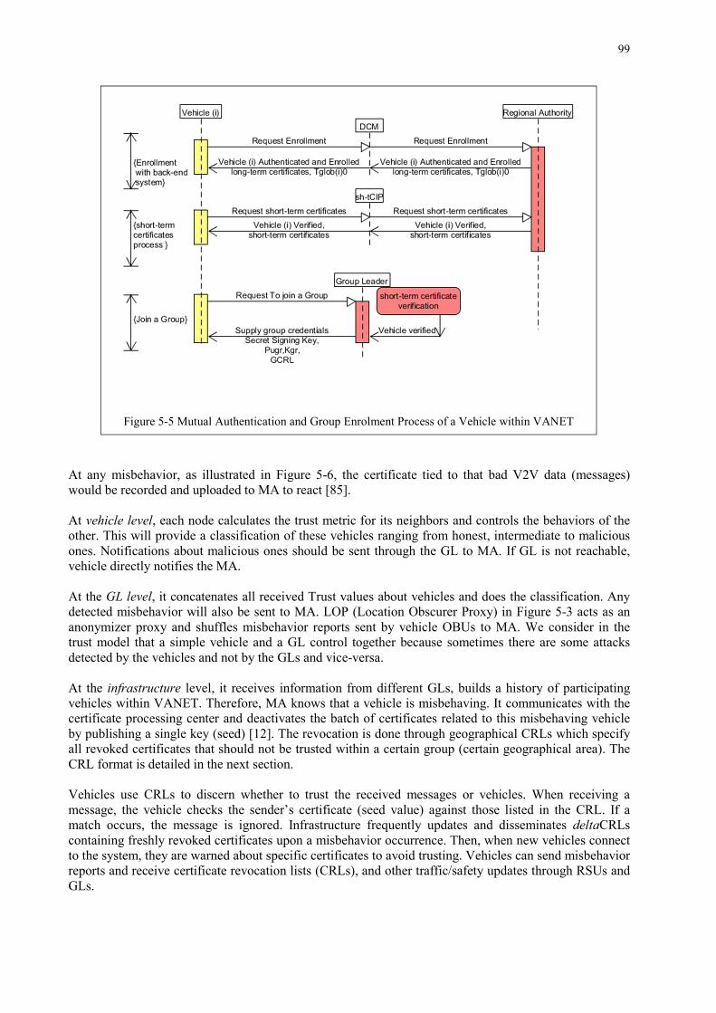
List of Figures Figure 2-1 Future vehicle design in VANET ............................................................................................... 8 Figure 2-2 VANETs Network ...................................................................................................................... 9 Figure 2-3 PKI Schema .............................................................................................................................. 17 Figure 2-4 Mapping OSI to ETSI Architectural Layers ............................................................................. 18 Figure 2-5 NHTSA Security System Design .............................................................................................. 18 Figure 3-1 Different Trust Evaluation Approaches .................................................................................... 36 Figure 3-2 Trust Model Components ......................................................................................................... 40 Figure 3-3 Vehicular Groups on Highway ................................................................................................. 42 Figure 3-4 Alert Message Dissemination Process within the Same Group ................................................ 43 Figure 3-5 Vehicular Groups ...................................................................................................................... 44 Figure 3-6 Enrollment and Join to Group Process of Vehicle i within the Trust Model ............................ 45 Figure 3-7 Monitoring Process of Vehicle i ............................................................................................... 46 Figure 3-8 Basic Safety Message Format ................................................................................................... 47 Figure 3-9 Normalization of Velocity Parameter for Direct Trust Calculation. ......................................... 48 Figure 3-10 The Handover Process of the Calculated Trust Values between Vehicles, GLs, RSU, and the Infrastructure. ............................................................................................................................................. 52 Figure 3-11 Trust Evaluation Process in Event Mode ................................................................................ 54 Figure 3-12 GL Trustworthiness Evaluation .............................................................................................. 55 Figure 3-13 Vehicles Evaluation based on Accordance Parameter Av(i)=1 .............................................. 58 Figure 3-14 Vehicles Evaluation based on Accordance Parameter Av(i)>1 .............................................. 58 Figure 3-15Vehicles Evaluation based on Accordance Parameter Av(i)<1 ............................................... 58 Figure 3-16 Average Total Trust Ttotm(i) Update Procedure at the Infrastructure(RSU) Level .................. 59 Figure 3-17 Steps Executed by MA upon Receiving Notifications from GLs or Vehicle ......................... 60 Figure 4-1 Delay of Group-based vs. PKI Scheme .................................................................................... 64 Figure 4-2 Simulation Area ........................................................................................................................ 66 Figure 4-3 Total Trust Variation of Three Vehicles in Medium Mode Scenario ....................................... 67 Figure 4-4 Total Trust Variation in Second Precision of Three Vehicles in Medium Mode Scenario ...... 67 Figure 4-5 Average Total Trust Variation of Vehicles with α, β Parameters in Medium Mode Scenario . 68 Figure 4-6 Comparison of Transmitted Messages/Vehicle in PKI vs. Trust Model Architecture ............. 69 Figure 4-7 Percentage of Warned Cars in Different Modes Scenarios....................................................... 70 Figure 4-8 Maximum Distance Traveled by Warning Messages in Different Scenarios ........................... 70 Figure 4-9 Comparison of Collided vs. Received Messages in Case of Warning Events in Medium Mode Scenario ...................................................................................................................................................... 70 Figure 4-10 Comparison of Collided vs. Received Messages in Case of Warning Events in Dense Mode Scenario ...................................................................................................................................................... 71 Figure 4-11 Basic Warning Message with DT Frame Format ................................................................... 71 Figure 4-12 Detected Percentage of Inspected-Malicious for Trust Model in Different Modes with 50% Malicious Cars Injected .............................................................................................................................. 72 Figure 4-13 Number of Honest, Inspected and Malicious Nodes in Medium Mode Scenario ................... 73 Figure 4-14 Average Lifetime of Potential GL with Variant Percentages of Malicious Vehicles ............. 73 Figure 5-1 Proposed System Architecture .................................................................................................. 95 Figure 5-2 Regional Authority Entities ...................................................................................................... 96 Figure 5-3 Infrastructure Entities ............................................................................................................... 97 Figure 5-4 Basics of the Revocation Framework ....................................................................................... 98 Figure 5-5 Mutual Authentication and Group Enrolment Process of a Vehicle within VANET ............... 99
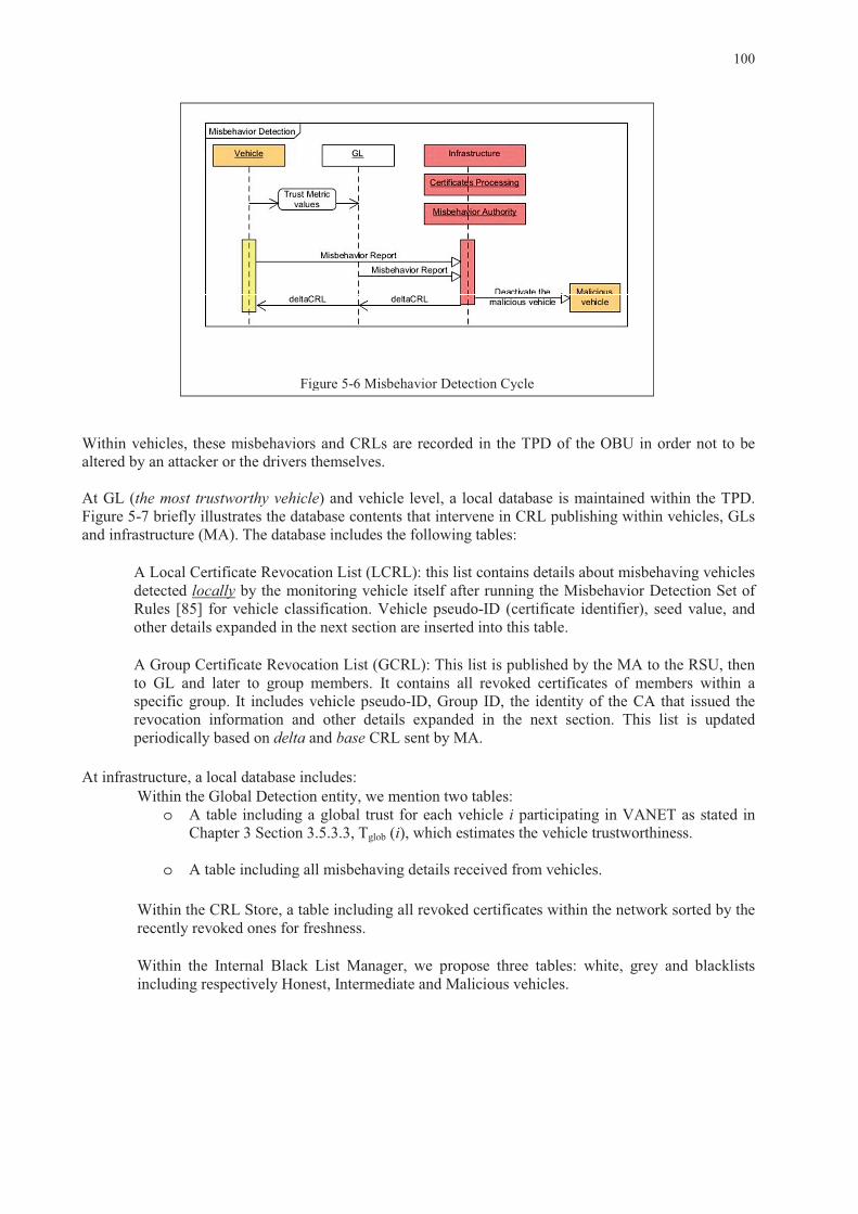
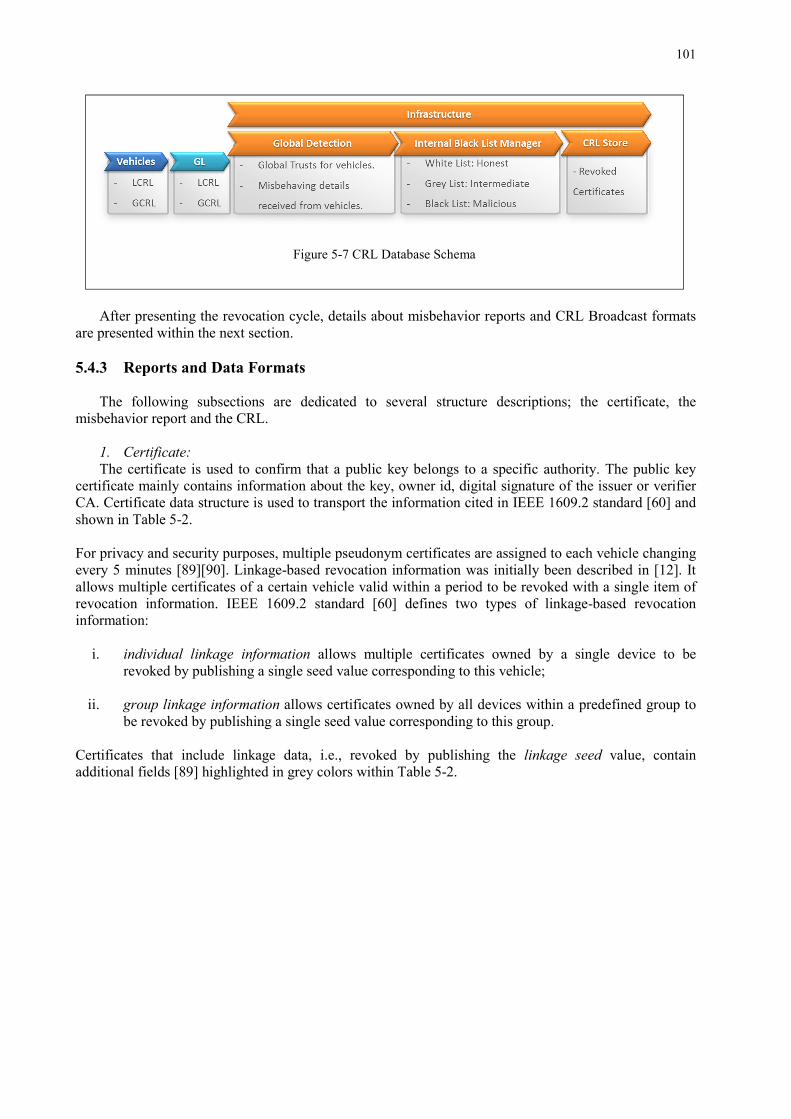
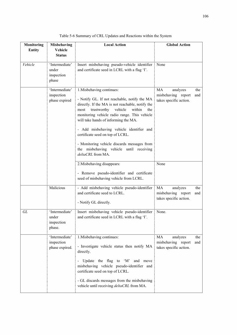
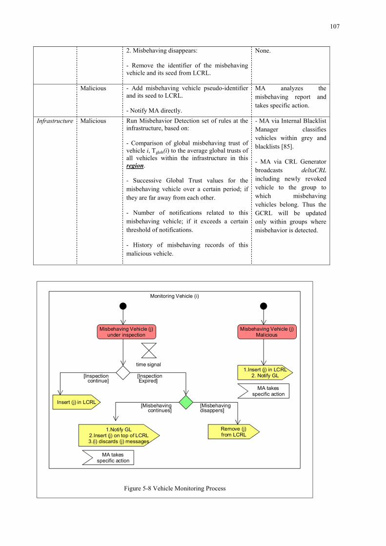
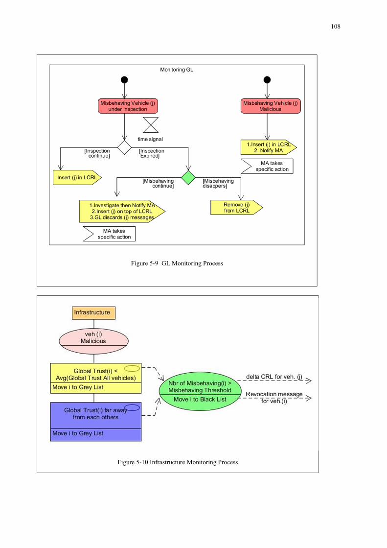
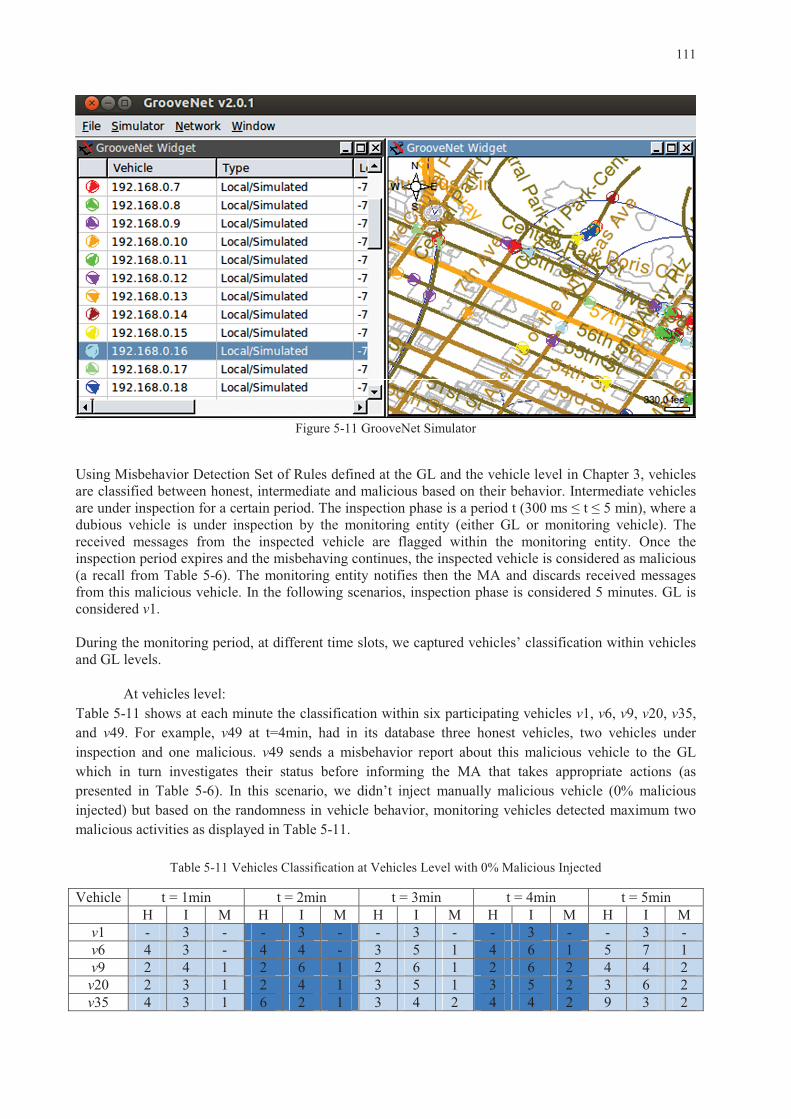
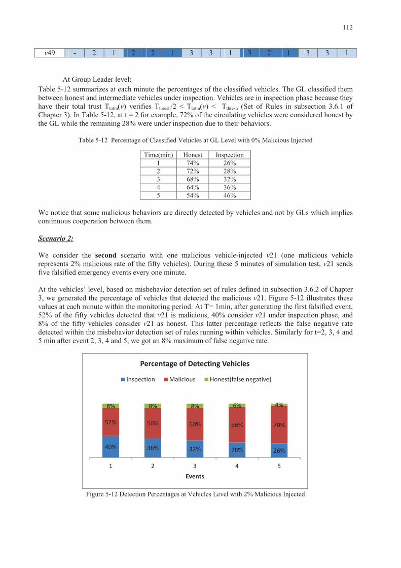
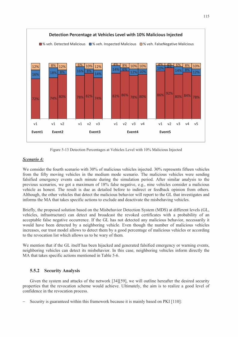
Figure 5-6 Misbehavior Detection Cycle ................................................................................................. 100 Figure 5-7 CRL Database Schema ........................................................................................................... 101 Figure 5-8 Vehicle Monitoring Process .................................................................................................... 107 Figure 5-9 GL Monitoring Process .......................................................................................................... 108 Figure 5-10 Infrastructure Monitoring Process ........................................................................................ 108 Figure 5-11 GrooveNet Simulator ............................................................................................................ 111 Figure 5-12 Detection Percentages at Vehicles Level with 2% Malicious Injected ................................. 112 Figure 5-13 Detection Percentages at Vehicles Level with 10% Malicious Injected ............................... 115
1
Chapter 1
Introduction
1.1 Background and Motivations
VANET is a specific type of ad-hoc network that provides data communication between vehicles
using wireless transmission. It is a highly dynamic network supporting different applications including safety and commercial ones; It supports exchanging information to improve road safety (alerts in case of accidents or of abnormal slowdowns, collaborative driving..) and allowing Internet access for passengers (collaborative networks, infotainment, etc.). The communication modes in VANETs can be Vehicle to Vehicle (V2V) or Vehicle to Infrastructure (V2I) through Road Side Units (RSUs) installed on the roadsides. A hybrid communication mode combining V2V and V2I modes is also supported.
The vehicular network is an unbounded and scalable network, characterized by high mobility, time-
varying vehicle density and rapidly changing network topology which induces congestion and needs collision control. Hence, the resulting error occurrence and the high delay affect the dissemination and the communication within the network. Such situations should be avoided because this can affect people’s life. Also, the exchanged messages between vehicles including those related to road safety may be falsified or eliminated by malicious entities which might cause accidents and endanger people’s life. Guarding against these misuse activities is critical. Thus VANET is an emergent technology with a promising future for intelligent transportation systems (ITSs) but with considerable challenges especially in its security.
Security is the state of being free from danger or threat; it can also be defined by a set of measures
that are taken to be safe or protected. Recently, many research works investigated security in VANET [1]- [58]. Some of them focused on the security infrastructures and architectures [12] [13] or standards [17] [21] and protocols. Others tackled the security attacks [31] and proposed related solutions. The authors in [23] reduced the propagation delay and worked on the authentication methods. In [15], methods for data delivery are proposed. In [46], the authors tried to balance between the privacy of the user and the requirement of traceability for the law enforcement authorities. Cryptographic approaches based on the Public Key Infrastructure (PKI) to distribute symmetric or asymmetric keys for message encryption and certificates for authentication are used in [45]. They believe that the group formation should be based on symmetric cryptographic schemes to speed up the processing and asymmetric cryptographic ones to strengthen the security.
However, the trustworthiness problem in VANET, where some different vehicles need to
communicate securely together and with the infrastructure, remains a challenging problem. Nodes receiving data need to trust the sender because sometimes even authenticated nodes can produce malicious issues. Some existing works investigate the trustworthiness evaluation [62]- [82] and the revocation problem [88]- [107], but there are still some challenges. First, few trust models define a misbehavior detection scheme combined with revocation criteria. Second, the revocation list parameters are still under investigation. This problem should be considered even for small-size networks as it constitutes an entity behavior constraint problem. In this context, several issues arise; the design of a secure architecture with an ability to face several known attacks, the credibility of the trustworthiness evaluation of participating entities within the vehicular network, the definition of a misbehavior detection system and a revocation process.
In our study, we focus on defining a security solution for V2V communications in VANET that mainly ensures a secure communication with confidence between the different participating vehicles.
•
•
3
1.3 Manuscript Organization This manuscript is structured in three parts: the first one is state of the art. The second is the trust
management system and the third is the misbehavior detection and revocation process. The remainder of this manuscript is organized as follows:
1. Part I: State of the Art
In Chapter 2, we provide a survey of VANETs security challenges and solutions. We review some
existing security frameworks. We discuss how well these solutions can satisfy the stringent security requirements and how well they can handle the various challenges that are often encountered in VANETs. We compare some of these solutions based on well-known security criteria. Moreover, we classify the different attacks known in VANET literature and their related solutions based on four categories and the VANET communication modes they affect. Finally, we draw attention to some open issues and technical challenges which may become new research areas for the future. 2. Part II: Trust Management System
Chapter 3 focuses on the proposed Trust Model interacting within groups. We propose a novel idea
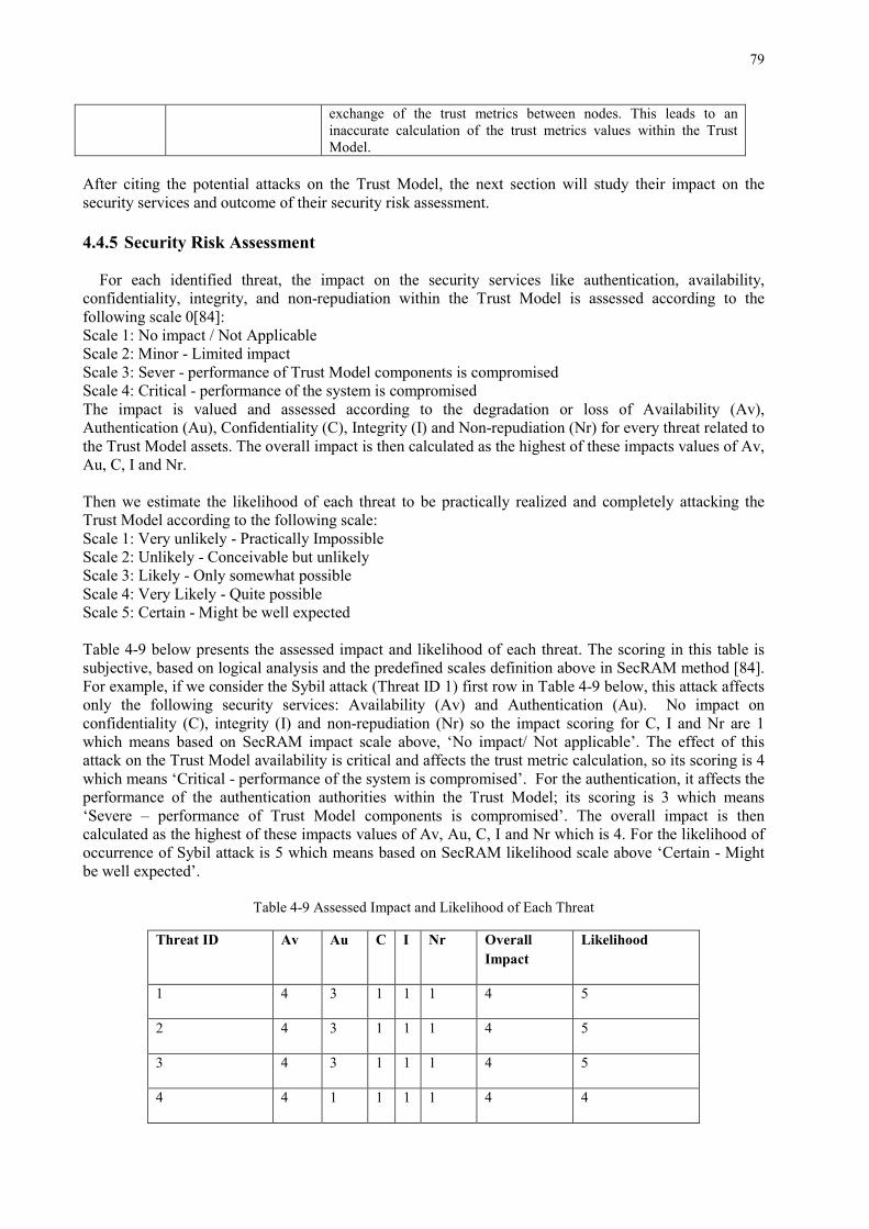
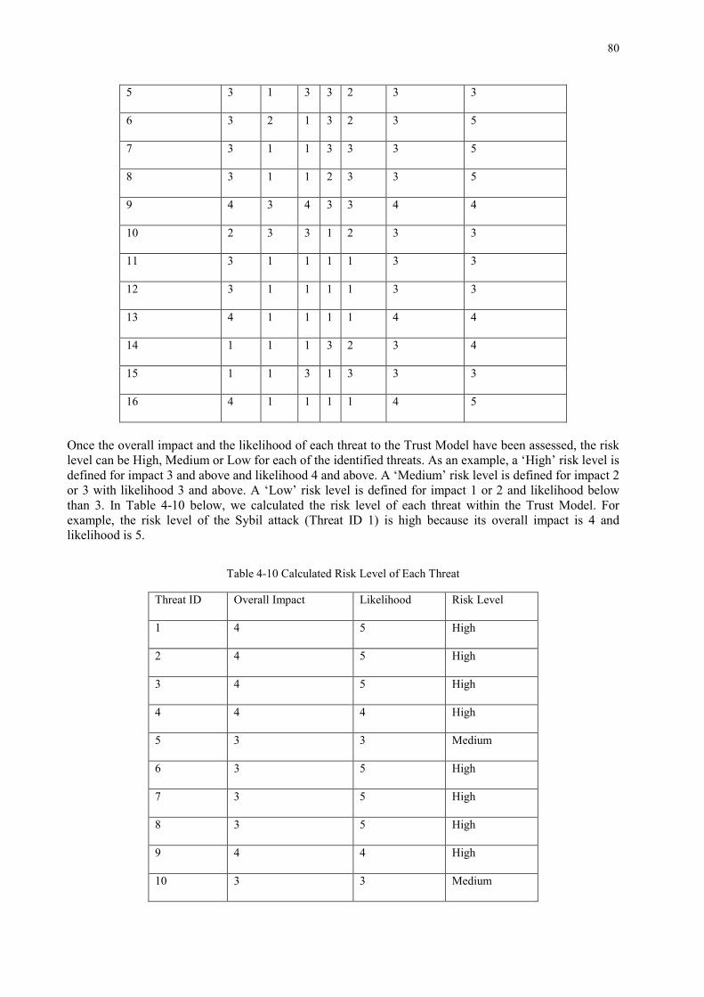
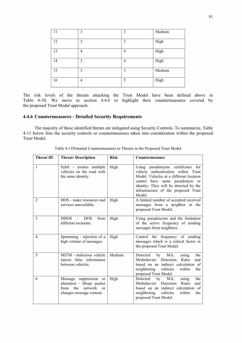
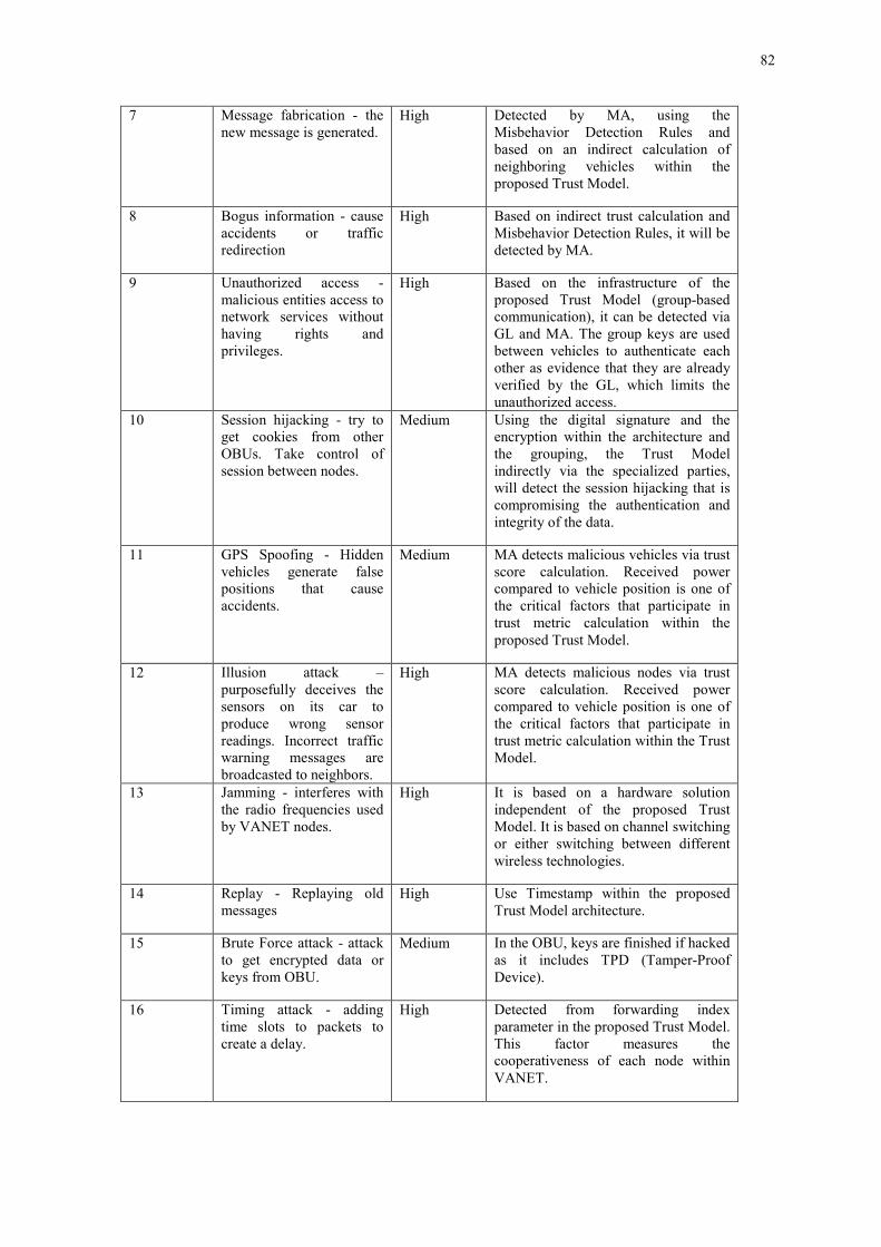
of trusting vehicles within a well-organized system. We first define a group formation technique. We form vehicular groups based on the speed, the direction and the position of the vehicles. This solution lessens the safety messages dissemination delay and the utilization of the infrastructure resources. Then we propose a Hybrid Trust Model for trustworthiness evaluation of participants within VANET. This model can detect the misbehaving nodes and elect the most trustworthy as potential Group Leaders. A combination of centralized and distributed entities, vehicles and infrastructure cooperate to achieve such objectives. Trust evaluation is based on different metrics to analyze vehicle behavior within the group while preserving the privacy of the participants and maintaining low network overhead. A Misbehavior Detection System based on a set of predefined rules is also designed within vehicles and in the infrastructure to detect, classify and revoke malicious vehicles. In Chapter 4, we evaluate the hybrid trust model. This evaluation includes two aspects: performance and risk analysis. For the performance, we evaluate the proposed Trust Model using the Groovenet simulator. Results show the efficiency of the proposed model to select the trustworthy vehicles and to monitor their behaviors, as well as to classify them and deactivate the malicious ones with low network overhead. For the risk analysis, we apply a security risk assessment methodology to our trust model. This methodology is used for identifying threats, assessing the risk involved, and defining approaches to mitigate them. The risk assessment includes assessment of the impact and likelihood of occurrence of attacks relevant to the identified threats, evaluation of the design principles of the hybrid trust model and validation of the built-in security and the mitigation actions of attacks. Based on this assessment, we demonstrate the resiliency of the proposed model to resist against many security attacks. 3. Part III: Misbehavior Detection and Revocation Process
In Chapter 5, we present a new framework for the certificate revocation process. Based on the
Misbehavior Detection System (MDS) designed within the Trust Model, the Misbehavior Authority identifies and excludes attackers from the vehicular network. The proposed MDS is using trust and reputation information provided by vehicles and misbehavior reports to guarantee the long-term functionality of the network. Trust Evaluation for participating nodes is updated continuously based on the vehicles’ behavior. Misbehavior reports are created if any anomaly is detected within VANET. Therefore, the revocation is done periodically through the Certificate Revocation List (CRL) which specifies all revoked vehicles. This results in a lightweight solution for CRL management and distribution
4
within a modular and secure infrastructure based on Public Key Infrastructure, group formation, and Trust evaluation. Finally, in Chapter 6, we conclude the thesis by summarizing the main contributions, and then we present our future work and open research prospects related to group-based trustworthiness evaluation and revocation process design for VANETs.
5
Part I: State of the Art
6
7
Chapter 2
Vehicular Ad-hoc Networks: Security Challenges and Solutions. 2.1 �������
In this chapter, we review some security frameworks in VANET. In particular, we present VANET security characteristics and investigate most of its security challenges as well as its security requirements. We detail the recent security architectures and the well-known security standards protocols. Also, we focus on a novel classification of the different attacks known in VANET literature and their related solutions. Then, we compare some of these solutions based on well-known security criteria in VANET. Finally, we draw attention to many open issues and technical challenges related to VANET security, which may constitute future research directions. 2.2 ������ ��
VANET aims to ensure safe driving by improving the traffic flow and therefore significantly reduce
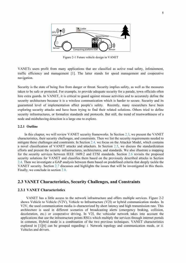
car accidents. The latter is solved by providing appropriate information to the driver or the vehicle. Moreover, any alteration of this real-time information may lead to system failure impacting people’s safety on the road. To ensure the smooth functioning of the system, it is imperative to secure this information, making it a top priority for security researchers. VANET is a special class of mobile ad-hoc network with predefined routes (roads). It relies on specific authorities for registration and management, Roadside Units (RSUs) and On-Board Units (OBUs). RSUs are widespread on the roadside to fulfill specific services, and OBUs are installed in the vehicles. All vehicles are moving freely on road network and communicating with each other or with RSUs and specific authorities. Using Dedicated Short Range Communication (DSRC) in a single or multi-hop, the communication mode is either V2V (Vehicle-to-Vehicle), V2I (Vehicle-to-Infrastructure) or hybrid. In the coming years, most of the vehicles will be equipped with an onboard wireless device (OBU), GPS (Global Positioning System), EDR (Event Data Recorder) and sensors (radar and ladar) as shown in Figure 2-1. These equipments are used to sense traffic congestions and status. Then they automatically take appropriate actions in the vehicle and relay this information through V2V or V2I within the vehicular network.
8
VANETs users profit from many applications that are classified as active road safety, infotainment, traffic efficiency and management [1]. The latter stands for speed management and cooperative navigation.
Security is the state of being free from danger or threat. Security implies safety, as well as the measures taken to be safe or protected. For example, to provide adequate security for a parade, town officials often hire extra guards. In VANET, it is critical to guard against misuse activities and to accurately define the security architecture because it is a wireless communication which is harder to secure. Security and its guaranteed level of implementation affect people’s safety. Recently, many researchers have been exploring security attacks and have been trying to find their related solutions. Others tried to define security infrastructures, or formalize standards and protocols. But still, the trend of trustworthiness of a node and misbehaving detection is a large one to explore.
2.2.1 Outline
In this chapter, we will review VANET security frameworks. In Section 2.3, we present the VANET characteristics, their security challenges, and constraints. Then we list the security requirements needed to mitigate these challenges and constraints. In Section 2.4, we focus on the Attacker Model, which contains a novel classification of VANET attacks and attackers. In Section 2.5, we discuss the standardization efforts and present the security infrastructures, architectures, and standards. We also illustrate a mapping for the security services between IEEE 1609.2 and ETSI standards. Section 2.6 revisits the proposed security solutions for VANET and classifies them based on the previously described attacks in Section 2.4. Then we investigate a GAP analysis between them based on predefined criteria that deeply tackle the VANET security. Section 2.7 discusses and highlights the issues that will be investigated in this thesis. Finally, we conclude in section 2.8. 2.3 ����������� ����� ����� �������������������������� 2.3.1 VANET Characteristics
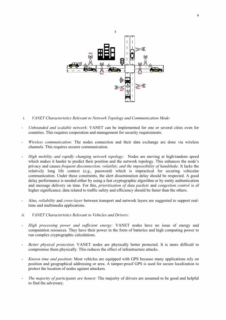
VANET has a little access to the network infrastructure and offers multiple services. Figure 2-2
shows Vehicle to Vehicle (V2V), Vehicle to Infrastructure (V2I) or hybrid communication modes. In V2V, the used communication media is characterized by short latency and high transmission rate. This architecture is used in different scenarios of broadcasting alerts (emergency braking, collision, deceleration, etc.) or cooperative driving. In V2I, the vehicular network takes into account the applications that use the infrastructure points RSUs which multiply the services through internet portals in common. Hybrid mode is a combination of the two previous techniques. VANET characteristics explored in [1] [6] can be grouped regarding: i. Network topology and communication mode, or ii. Vehicles and drivers.
Figure 2-1 Future vehicle design in VANET
9
i. VANET Characteristics Relevant to Network Topology and Communication Mode:
- Unbounded and scalable network: VANET can be implemented for one or several cities even for countries. This requires cooperation and management for security requirements.
- Wireless communication: The nodes connection and their data exchange are done via wireless channels. This requires securer communication.
- High mobility and rapidly changing network topology: Nodes are moving at high/random speed which makes it harder to predict their position and the network topology. This enhances the node’s privacy and causes frequent disconnection, volatility, and the impossibility of handshake. It lacks the relatively long life context (e.g., password) which is impractical for securing vehicular communication. Under these constraints, the alert dissemination delay should be respected. A good delay performance is needed either by using a fast cryptographic algorithm or by entity authentication and message delivery on time. For this, prioritization of data packets and congestion control is of higher significance; data related to traffic safety and efficiency should be faster than the others.
- Also, reliability and cross-layer between transport and network layers are suggested to support real-
time and multimedia applications.
ii. VANET Characteristics Relevant to Vehicles and Drivers:
- High processing power and sufficient energy: VANET nodes have no issue of energy and computation resources. They have their power in the form of batteries and high computing power to run complex cryptographic calculations.
- Better physical protection: VANET nodes are physically better protected. It is more difficult to compromise them physically. This reduces the effect of infrastructure attacks.
- Known time and position: Most vehicles are equipped with GPS because many applications rely on
position and geographical addressing or area. A tamper-proof GPS is used for secure localization to protect the location of nodes against attackers.
- The majority of participants are honest: The majority of drivers are assumed to be good and helpful
to find the adversary.
s
Figure 2-2 VANETs Network
−
−
−
−
−
−
−
−
−
11
2.3.3 VANET Security Requirements (Services) The security services increase the security of processing and data exchange in VANET. The security
requirements include:
• Authentication: Ensures that the message is generated by a legitimate user, i.e., using a certificate or a pseudonym for sender verification [8].
• Availability: By resisting a DoS (Denial of Service) attack we assure normal functioning because a delay of seconds makes the disseminated message meaningless [4].
• Confidentiality: Involves a set of rules or a promise that limits access restrictions on certain
resources. It is achieved using encryption or exchanging special messages between OBUs and RSUs as some form of data verification [9].
• Non-repudiation: A sender cannot deny sending a message as they are already known to have done so
on good authority. The attacker can be retrieved even after harm via the Tamper-Proof Device (TPD) [4].
• Integrity: No alteration of data. A digital signature is used for message and data integrity [3] [10]. • Privacy and Anonymity: Hide the identity of the user against unauthorized nodes using temporary and
anonymous keys, thus affording location privacy; no one can track the trajectory of any node. • Data verification: The verification of data consistency with similar messages is used for detecting
data correctness, especially between neighboring vehicles. This detects false messaging within the vehicular network.
• Access control: All nodes work according to rules and roles privileges [11]. • Traceability and Revocability: Although a vehicle’s real identity should be hidden from others, there
should still be a component with the ability to obtain the vehicles’ real identities to revoke them for future use.
• Error detection: Detects malicious and erroneous transmission. • Liability identification: Accountability or user identification during communication. Messages can be
used to identify users. • Flexibility and efficiency: The flexibility in the security architecture and system design is significant,
although it is essentially designed for traffic safety application that requires less time and bandwidth. This makes the channel efficiency crucial in its consequent low delay.
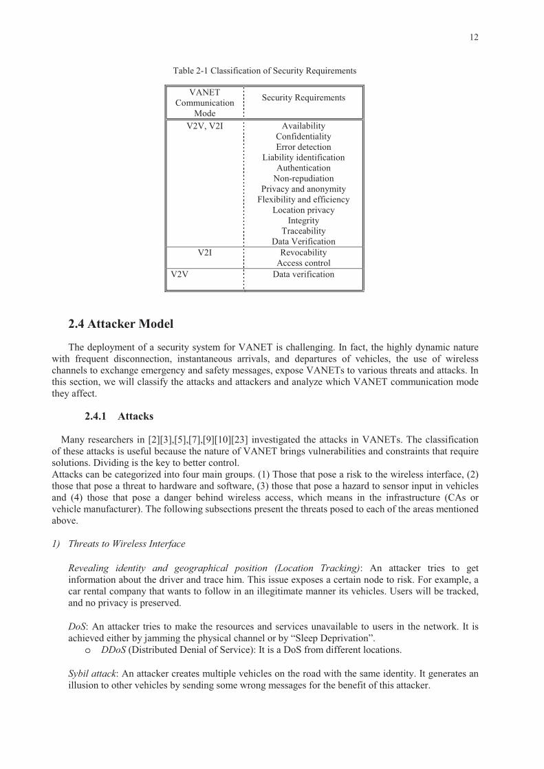
After defining and analyzing the security requirements, we classify them in Table 2-1 based on their needs in VANET communication mode, either for V2V, V2I or both. For each VANET communication mode, we define its prerequisites of security services.
•
•
•
•
•
•
•
•
•
•
•
•
•
•
•
•
•
•
•
•
•
15
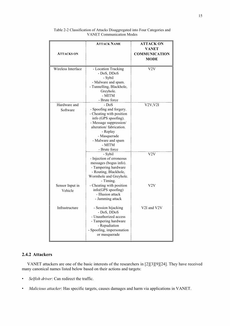
2.4.2 Attackers VANET attackers are one of the basic interests of the researchers in [2] [3] [9] [24]. They have received many canonical names listed below based on their actions and targets: • Selfish driver: Can redirect the traffic.
• Malicious attacker: Has specific targets, causes damages and harm via applications in VANET.
Table 2-2 Classification of Attacks Disaggregated into Four Categories and VANET Communication Modes
• Pranksters: Attacker does things for its entertainment, such as DoS or message alteration (hazard warning) to cause road traffic congestion for example.
• Greedy drivers: Try to attack for their benefit. For example, sending an accident message may cause
congestion on the road, or sending false messages for freeing up the road. • Snoop/eavesdropper: Attacker tries to collect information about other resources. • Industrial insiders: During firmware update or key distribution malicious employees tamper with the
hardware. The attackers are classified into: - Insider vs. outsider: Insider represents an authenticated user on the network vs. an outsider with
limited capacity to attack.
- Malicious vs. rational: Malicious represents any attacker with personal benefit vs. rational which has personal and predictable profit.
- Active vs. passive: Active attacker generates signals or packets vs. a passive one that only senses the network.
- Local vs. extended: Local attacker works with limited scope even on several vehicles or base stations vs. extended attacker which broadens its scope by controlling several entities scattered across the network.
After detailing the classified attacks and attackers, we will detail in the next section the standardization and the recent project efforts. 2.5 Standardization Efforts
Infrastructure is an underlying foundation for a system. Security architecture is a security design. It addresses the necessities and potential risks involved in a certain environment and specifies when and where to apply security controls. Standard provides detailed requirements on how policy must be implemented. In VANET, many groups [12]- [16] have investigated the security architectures and infrastructures. They generated either security standard protocols [17] [21] or defined security architecture [18]. Other projects, e.g., Scoop@F [19], C-Roads [20], are currently investigating the security of the ITS (Intelligent Transport System). In the following, we detail the most popular security infrastructure namely PKI (Public Key Infrastructure), the recent VANET security architectures and the well-known security standards protocols. 2.5.1 Security Infrastructure: PKI
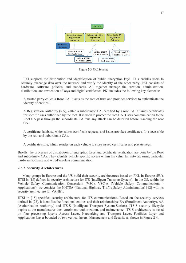
Exploring the VANET security infrastructures, PKI is the most used one. It is shown in Figure 2-3.
•
•
•
•
18
EA validates (authenticates and grants) that an ITS-S is trusted to function in ITS communication. AA provides ITS-S proof to use specific services by issuing authorization tickets. The CI (Canonical Identifier) is globally unique for an ITS-S facing the enrolment credentials.
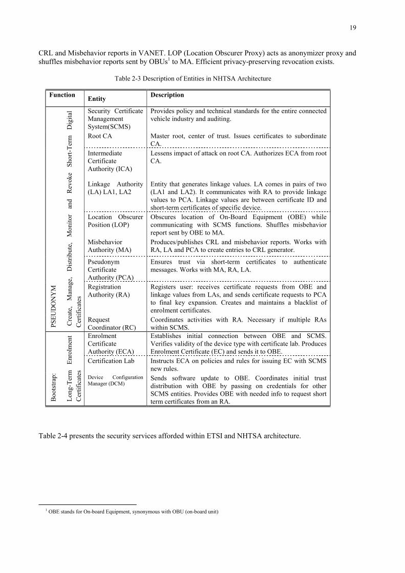
NHTSA proposed a security architecture [12] based on PKI. It contains functional entities based on
long-term enrolment certificates for OBU (bootstrap functions), and short-term digital certificates (pseudonym functions). Their primary issue is trust. The entities of the NHTSA architecture are shown in Figure 2-5. Their functionalities are detailed in Table 2-3. Within their proposal, V2V communication consists of two types of messages: BSM (Basic Safety Message) and security information message. For BSM, the digital signature and certificate are used for verification purposes. For communications between vehicles and SCMS (Security Certificate Management System), the asymmetric encryption ECIES (Elliptic Curve Integrated Encryption Scheme) is used for confidentiality and the digital signature ECDSA (Elliptic Curve Digital Signature Algorithm) is used to validate the device. For communications inside the SCMS (entity to entity), the symmetric encryption AES-CCM (Advanced Encryption Standard- Counter with CBC-MAC) is used for confidentiality with MAC (Message Authentication Code) for integrity, and together they provide authenticity. This security architecture ensures privacy against insiders and outsiders; a single SCMS component cannot link any two certificates to the same device (no tracking), and no stored information within SCMS can link certificates to a particular vehicle or owner. MA (Misbehavior Authority) ensures the continuation of the trusted nodes only, by producing/publishing
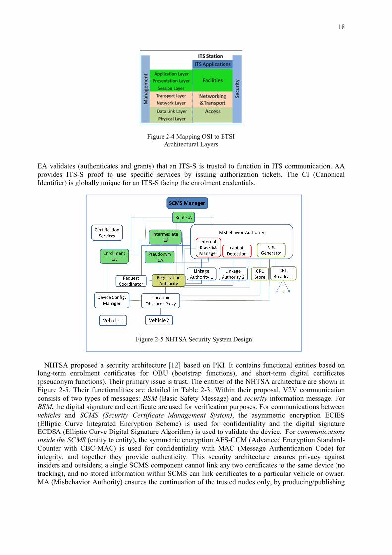
Figure 2-4 Mapping OSI to ETSI Architectural Layers
Figure 2-5 NHTSA Security System Design
19
CRL and Misbehavior reports in VANET. LOP (Location Obscurer Proxy) acts as anonymizer proxy and shuffles misbehavior reports sent by OBUs1 to MA. Efficient privacy-preserving revocation exists.
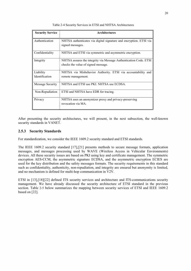
Table 2-4 presents the security services afforded within ETSI and NHTSA architecture.
1 OBE stands for On-board Equipment, synonymous with OBU (on-board unit)
Table 2-3 Description of Entities in NHTSA Architecture
Function Entity Description
PSEU
DO
NY
M
Cre
ate,
M
anag
e,
Dis
tribu
te,
Mon
itor
and
Rev
oke
Shor
t-Ter
m
Dig
ital
Cer
tific
ates
Security Certificate Management System(SCMS)
Provides policy and technical standards for the entire connected vehicle industry and auditing.
Root CA Master root, center of trust. Issues certificates to subordinate CA.
Intermediate Certificate Authority (ICA)
Lessens impact of attack on root CA. Authorizes ECA from root CA.
Linkage Authority (LA) LA1, LA2
Entity that generates linkage values. LA comes in pairs of two (LA1 and LA2). It communicates with RA to provide linkage values to PCA. Linkage values are between certificate ID and short-term certificates of specific device.
Location Obscurer Position (LOP)
Obscures location of On-Board Equipment (OBE) while communicating with SCMS functions. Shuffles misbehavior report sent by OBE to MA.
Misbehavior Authority (MA)
Produces/publishes CRL and misbehavior reports. Works with RA, LA and PCA to create entries to CRL generator.
Pseudonym Certificate Authority (PCA)
Ensures trust via short-term certificates to authenticate messages. Works with MA, RA, LA.
Registration Authority (RA)
Registers user: receives certificate requests from OBE and linkage values from LAs, and sends certificate requests to PCA to final key expansion. Creates and maintains a blacklist of enrolment certificates.
Request Coordinator (RC)
Coordinates activities with RA. Necessary if multiple RAs within SCMS.
Boo
tstra
p:
Long
-Ter
m
Enro
lmen
t C
ertif
icat
es
Enrolment Certificate Authority (ECA)
Establishes initial connection between OBE and SCMS. Verifies validity of the device type with certificate lab. Produces Enrolment Certificate (EC) and sends it to OBE.
Certification Lab Instructs ECA on policies and rules for issuing EC with SCMS new rules.
Device Configuration Manager (DCM)
Sends software update to OBE. Coordinates initial trust distribution with OBE by passing on credentials for other SCMS entities. Provides OBE with needed info to request short term certificates from an RA.
20
After presenting the security architectures, we will present, in the next subsection, the well-known security standards in VANET. 2.5.3 Security Standards For standardization, we consider the IEEE 1609.2 security standard and ETSI standards. The IEEE 1609.2 security standard [17], [21] presents methods to secure message formats, application messages, and messages processing used by WAVE (Wireless Access in Vehicular Environments) devices. All these security issues are based on PKI using key and certificate management. The symmetric encryption AES-CCM, the asymmetric signature ECDSA, and the asymmetric encryption ECIES are used for the key distribution and the safety messages formats. The security requirements in this standard such as confidentiality, authenticity, non-repudiation, and integrity are ensured but anonymity is limited, and no mechanism is defined for multi-hop communication in V2V. ETSI in [13], [18] [22] defined ITS security services and architecture and ITS-communications security management. We have already discussed the security architecture of ETSI standard in the previous section. Table 2-5 below summarizes the mapping between security services of ETSI and IEEE 1609.2 based on [22].
Table 2-4 Security Services in ETSI and NHTSA Architectures
Security Service Architectures
Authentication NHTSA authenticates via digital signature and encryption. ETSI via signed messages.
Confidentiality NHTSA and ETSI via symmetric and asymmetric encryption.
Integrity NHTSA assures the integrity via Message Authentication Code. ETSI checks the value of signed message.
Liability Identification
NHTSA via Misbehavior Authority. ETSI via accountability and remote management.
Message Security NHTSA and ETSI use PKI. NHTSA use ECDSA.
Non-Repudiation ETSI and NHTSA have EDR for tracing.
Privacy NHTSA uses an anonymizer proxy and privacy-preserving revocation via MA.
21
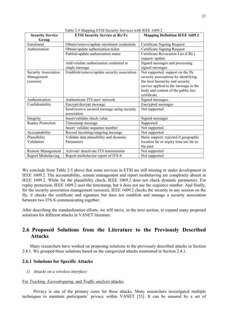
We conclude from Table 2-5 above that some services in ETSI are still missing or under development in IEEE 1609.2. The accountability, remote management and report misbehaving are completely absent in IEEE 1609.2. While for the plausibility check, IEEE 1069.2 does not check dynamic parameters. For replay protection, IEEE 1609.2 uses the timestamp, but it does not use the sequence number. And finally, for the security association management (session), IEEE 1609.2 checks the security in any session on the fly, it checks the certificate and signature but does not establish and manage a security association between two ITS-S communicating together.
After describing the standardization efforts, we will move, in the next section, to expand many proposed solutions for different attacks in VANET literature. 2.6 Proposed Solutions from the Literature to the Previously Described
Attacks Many researchers have worked on proposing solutions to the previously described attacks in Section 2.4.1. We grouped these solutions based on the categorized attacks mentioned in Section 2.4.1. 2.6.1 Solutions for Specific Attacks
1) Attacks on a wireless interface:
For Tracking, Eavesdropping, and Traffic analysis attacks:
Privacy is one of the primary cures for these attacks. Many researchers investigated multiple techniques to maintain participants’ privacy within VANET [53]. It can be ensured by a set of
Table 2-5 Mapping ETSI Security Services with IEEE 1609.2 Security Service
Group ETSI Security Service at Rx/Tx Mapping Definition IEEE 1609.2
Obtain/update authorization ticket Certificate Signing Request Publish/update authorization status Certificate Revocation List (CRL)
request/ update Add/validate authorisation credential to single message
Signed messages and processing signed messages
Security Association Management (session)
Establish/remove/update security association
Not supported: support on the fly security associations by identifying the trust hierarchy and security service applied to the message in the body and content of the public key certificate.
Authentication Authenticate ITS user/ network Signed messages. Confidentiality Encrypt/decrypt message Encrypted messages
Send/receive secured message using security association
Not supported
Integrity Insert/validate check value Signed messages Replay Protection Timestamp message Supported
Insert/ validate sequence number Not supported Accountability Record incoming/outgoing message Not supported Plausibility Validation
Validate data plausibility and dynamic Parameters
Basic support: rejected if geographic location far or expiry time too far in the past.
Remote Management Activate/ deactivate ITS transmission Not supported Report Misbehaving Report misbehavior report of ITS-S Not supported
22
anonymous keys changing according to the driving speed or via pseudonyms that cannot be linked to the true identity of the user or the vehicle [25] or either via group signatures [12] [26] [27]. ETSI standard in [28] specifies the privacy management for a node based on anonymity, unobservability, pseudonyms, and unlinkability. The communication between nodes is done using the SA (Security Association) and key management. The authors in [3] propose to preload anonymous keys in TPD which are certified by CA and traced back to the Electronic License Plate (ELP). [29] propose to keep node identity and location private, thus using a decentralized group authentication with a set of anonymous keys, pseudonyms, group signatures and ECPP (Efficient Conditional Privacy Preserving) protocol for anonymous authentication. In [30], the vehicles use many temporary certificates (pseudonyms) from their TPD that cannot be linked with each other. [24] propose to use variables MAC (Media Access Control) and IP addresses to separate the addresses from the identities of vehicles and drivers [23]. [31] suggest VIPER (Vehicle-To-Infrastructure Communication Privacy Enforcement Protocol) for V2I communications. For the vehicle’s group formation, the group signature is used to sign message on behalf of the group, not revealing the identity of the signer, which prevents tracking and assures privacy [26]. Only the group manager can unlock the identity of the user and trace them via a secret trapdoor. In [12], V2V inside groups use a secret-key for their basic authentication. Group or ring signatures enhance privacy by saving communication most efficiently. In [27], a non-interactive authentication scheme is presented, providing privacy among drivers assembled in groups for V2V communication networks; drivers may change their own set of public keys frequently without control from the third trusted party (TTP). Also, we can mitigate these attacks by encrypting the data. The authors in [2] propose asymmetric cryptography via NMD (Non-Disclosure Method) routing protocol. [12] suggests the symmetric encryption for beacons to avoid being tracked. The security architecture for V2V and V2I communication adopted in [14], [15] [23] [32] succeeded to protect the privacy of participants and was very efficient regarding computing capabilities and communication bandwidth using the asymmetric/symmetric cryptography and tamper-resistant hardware. For Information Disclosure: The authors in [2] propose SMT (Secure Message Transmission) and NMD routing protocol to solve this issue via MAC and asymmetric cryptography. For DOS attack:
It can be lessened using the digital signature [24], specific authentication methods [23], routing protocols [1] or trustworthiness of a node [34]. A digital signature is used for secure and reliable message communication and authentication [35]. Digitally signing data acts as proactive security for it [1], also customized hardware with non-public protocols let attackers take time to penetrate to the system. [36] suggests the usage of short-lifetime private and public keys with a hash function. For authentication, Tesla++ [33] is an authentication method used as an effective alternative to signatures. It uses symmetric crypto with delayed key disclosure. It is secure and prevents memory-based DoS attacks. It reduces the memory requirement at the receiver end for the authentication mechanism. For the routing protocol, [2] applies the SEAD (Secure and Efficient Ad-hoc Distance Vector) or ARIADNE routing protocol that uses one-way hash function and symmetric cryptography. Concerning the trustworthiness of a vehicle, [34] proposes a Trust Model that calculates the trust metric values of nodes participating in VANET. One of its critical factors consists of limiting the number of accepted received messages from neighbors. Once exceeding a certain threshold (which is the case in DOS attack), using a fuzzy-based approach, a direct report is sent to MA to deactivate the attacker.
23
For Sybil attack:
Deploy a central Validation Authority (VA), which validates entities in real time directly or indirectly using temporary certificates [37]. Use PKI for key distribution and revocation [38]. Apply the registration, the ECDSA for signature and use timestamp per vehicle [8]. [39] proposes to use approved certification. In case of authentic and secure links with trusted nodes, [40] proposes validating unknown nodes with the method of secure location verification. [9] suggests position verification by analyzing the signal strength and radio resource testing. [41] advocates strengthening the authentication mechanism by the use of distance bounding protocols based on cryptographic techniques. In [9], RobSAD (Robust Sybil Attack Detection) for abnormal/normal trajectory ensures higher detection rate and lower system requirements. It can detect attacks independently by comparing digital signatures for the same motion trajectories. [42] proposes many privacy-preserving schemas with VANET architecture generating certificates/pseudonyms and monitoring vehicles then reporting to CA. [43] proposes to use onboard radar (virtual eye). Vehicles can see surrounding vehicles and receive reports of their GPS coordinates. By comparing they can detect the real position and the malicious vehicles. In [3], location is used to prevent Sybil attacks by checking its logical place. A vehicle receives a message, examines the certificate, its lifetime and location. If it is correct and in a logical location, it accepts the message, or else it reports to the nearest CA. They also use TCRL (Timely geographical CRL) that contains freshly revoked CRLs of a specific area. Finally, [44] compares different Sybil attacks solutions. For Malware and Spamming:
The digital signature of software and sensors is a must. Using trusted hardware makes impossible to change existing protocols and values, except by authorized nodes [41]. For Man in the Middle attack: Use strong authentication methods such as digital certificates and confidential communication with key or powerful cryptography [9]. Include several authentication schemes mentioned in [45] where anonymity, pseudonyms, trust, and privacy are ensured via short-lived keys changing frequently and RSU used for authentication and key distribution. In [36], a decentralized lightweight authentication scheme for V2V is given to protect valid users in VANETs from malicious attacks based on the concept of transitive trust relationships. [46] proposes an authentication via MM (Membership Manager) which can detect misbehaving nodes via RSUs that trace vehicles. In [47], an efficient cooperative message authentication permits vehicle users to cooperatively authenticate some message-signature pairs without trusted agent using Public Key Cryptography (PKC) and Secret Key Cryptography (SKC). For Brute force attack:
Use strong encryption and key generation algorithms unbreakable within a reasonable running
time [49]. Then unauthorized access is prohibited.
2) Attacks on hardware and software
For Message Tampering: Use similarity algorithm [50], data correlation [26] and challenge-response authentication method [33] to prove the reliability of the messages. [50] proposes a trust and reputation management framework based on similarity algorithm and trust of messages content between vehicles to help the driver to believe or not believe a received message. By calculating the trust value if it surpasses a threshold they take appropriate action and rebroadcast the message. Otherwise, they drop it.
24
In [26], a novel group signature based on a security framework assures authenticity, integrity, anonymity, and accountability. An access control approach and probabilistic signature verification scheme are used to detect the tampered messages for the unauthorized node. Based on the tamper resistance device, it correlates data from vehicles and cross-validates it via a set of rules. The security layer of this framework is composed of capability check, signature generation, firewall, signature verification, authorization check, anomaly check. In [33], a challenge-response authentication method is proposed; it is a combination of digital signature and challenge-response authentication. It is used to minimize the false message. A receiver getting any message sends a challenge to the sender. By replying, it transmits its location and timestamp to prove its authenticity. The location can tell us if the vehicle was in the vicinity of an accident, which increases the reliability of the safety message. For Spoofing and Forgery attacks: Use Vehicular PKI (VPKI) for authentication between vehicles [51]. Or sign warning messages [52], or establish group communications [54], or include a non-cryptographic checksum per message sent and apply plausibility checks on incoming ones [25], use cryptographic certificate via routing protocol ARAN (Authenticated Routing for Ad-hoc network) [1]. Or use onboard radar (virtual eye) [43] [1], then the vehicle can detect the real position and the malicious vehicles. For VPKI, it is a set of trusted third parties, one CA in each country, with delegated CAs in regions. CAs mutually recognize vehicles in different areas. Each vehicle has its own private and public keys and short lifetime of certificates with anonymous keys changing according to the driver’s speed [51]. Only legal authorities can correlate between the Electronic License Plate of a vehicle and its pseudonyms. So a disseminated signed message with certificate attached is authenticated via CA. Thus the communication between authenticated users is only established securely. Use ECDSA for digital signature [47]. It provides secure and fast dissemination of information; after validating the public key, it authenticates the private key of a user signing a message. For group communication [54], keys can be managed by a group key management system. An intruder would not be able to communicate with the group. Drivers are organized into groups with a shared public key between members [55] [35]. In case of malicious behavior, the identity of the signer can be revealed only by the TTP. In [35], they use SECA (Security Engineering Cluster Analysis) for securing the group. For beacons security, they use the certificate and digital signature while for multi-hop security, the geographical position is used. For Message Saturation:
[25] proposes to limit the message traffic to V2I/I2V. They implement station registration so only registered vehicles accept and process messages received from ITS infrastructure in their radio range. This reduces the frequency of beaconing and adds a source of identification (equivalent to IP address) in V2V messages. The authors in [23], [56] meanwhile try to limit the flooding of signed messages, built on location-based grouping and aggregation signature. For Replay attack:
Use time stamping technique for sensitive packets [43], or timestamp all messages by broadcasting time (UTC or GNSS), or digitally sign and include a sequence number in each message [25], beside cryptographic certificate or symmetric cryptography and MAC via ARAN and ARIADNE routing protocol [2].
25
For Node Impersonation: Use variables MAC and IP addresses for V2V and V2I communications [39], or authenticate via digital certificates [37] [41]. [41] proposes to strengthen the authentication mechanism using the distance bounding protocols based on cryptographic techniques. Use cryptographic certificate via ARAN routing protocol as mentioned in [2]. For surpassing Masquerading: [25] proposes to include an authoritative identity in each message and authenticate it, or, as suggested in [47], use the digital signature and sequence number. For resisting against Routing attacks (Blackhole, Greyhole, Wormhole, and Tunneling):
The digital signature of software and sensors are used. In ARAN, ARIADNE and SEAD routing protocol [2] cryptographic certificate, symmetric cryptography, MAC (Message Authentication Code) and one-way hash function are used respectively to solve these issues. In [9], HEAP an efficient technique is proposed to defend against wormhole attacks in the network. It is based on AODV protocol. It uses a geographical leash to limit the traveled distance from the source to destination; if the threshold is surpassed, then the packet is dropped. They also propose the TIK (TESLA with Instant Key disclosure) authentication protocol. [48] presents various mechanisms to improve different ad-hoc routing protocols for secure routing process by enhancing the trust among different nodes in VANETs. For timing attacks:
Time stamping mechanism is used for packets of delay-sensitive applications in a trusted platform with strong cryptographic modules [9], [24] [36].
3) Attacks on sensor input in the vehicle
For jamming attacks:
The authors in [57] propose to switch the transmission channel or use the frequency-hopping technique. While [35] suggests switching between different wireless technologies. For GPS Spoofing or Faking Position or Illusion attack: Use a signature with a positioning system to accept only authentic location data [58] [25], implement differential monitoring to identify unusual changes in position [25], or calculate a reputation score for safety application [35] by analyzing and filtering received queries to detect malicious and incorrect position. Hence potential adversaries are detected and ejected from VANET.
4) Attacks on Infrastructure:
For Key and/or Certificate Replication that cause Unauthorized Access:
Use certified and disposable keys, check the validity of the digital certificates in real time via CRL [24], or use the revocation protocols instead of CRL [3]. Use the cross certification between different CAs involved in VANETs security scheme [39], or adopt hierarchical distributed CAs with trust going through a long chain [30].
26
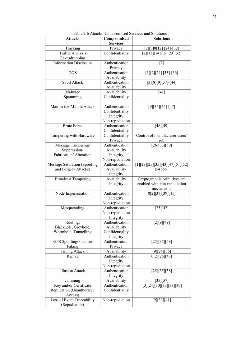
A “freshness” concept in [38] provides a constant verification time independent of the number of revoked certificates. Thus there is no need for PKI to distribute the CRL and OBUs to maintain them. This reduces the storage requirement at OBUs. [33] proposes to revoke the certificate either when cryptographic keys are compromised or when a fraudulent user issues signed certificates to transmit fake info. The certificate consists of a public key, certificate lifetime, signature of CA and CRL appended. Some of the suitable revocation protocols are mentioned in [3]: RTPD (Revocation Tamper-Proof Device), if activated in any vehicle, prohibits it from sending messages, and DRP (Distributed Revocation Protocol) which allows vehicles to communicate and accuse others that misbehave and when a possible report to CA. Then their TPD will no longer be able to sign messages. For Loss of Event Traceability (Repudiation): The authors in [41] recommend using trusted hardware for which it is impossible to change the existing protocols and values except by authorized ones. As per [33], reading and updating from sensors must be authenticated and verified, e.g., by a challenge/response mechanism. While [9] proposes the PVN (Plausibly Validation Network) to collect raw data from sensors and antenna to check if plausible or not. Finally, ETSI in [13] proposes for attack countermeasures to use the audit log and the remote activation and deactivation of nodes. In Table 2-6, we present the previously described attacks, their related compromised services, and their proposed solutions.
27
Table 2-6 Attacks, Compromised Services and Solutions Attacks Compromised
2.6.2 GAP Analysis Between Different Solutions When performing a gap analysis in VANET, the aim is to identify gaps in missing/necessary needs about what outcomes are desired. One must compare what has been done in the area, and compare this to the ambitions of what to aim for. There will probably be a gap in-between, which in that case must be identified. When this identifying process is completed the analysis hopefully proposes a solution to how to fill the gap. Researchers in VANET tried to bypass the scalability problems and save communication most efficiently. They aimed to reduce the delay in propagation. They worked on authentication and data delivery and tried to propose how to trust messages between vehicles. They tried to find a balance between the need to preserve user privacy and the traceability requirement for law enforcement authorities. They used cryptographic approaches based on PKI to distribute symmetric or asymmetric keys for message encryption, and certificates for authentication. They trusted group formation based on symmetric and asymmetric cryptographic schemes to speed the processing and strengthen the security and the privacy. The encrypted data is used to prevent tracking. They used digital signature and trust model at the receiver end, to prevent DoS. They validated data in real time, by analyzing signal strength or buying virtual eyes to detect Sybil attacks. They used the digital signature or transitive relationship for malware and spamming detection. They suggested strong encryption and key generation algorithms unbreakable within a reasonable running time to resist brute force attacks. They proposed similarity algorithm to check and detect tampering by calculating trust value surpassing a certain threshold. They adopted the group communication to limit the unauthorized access. They reduced the frequency of sending to limit the message saturation. They used special routing protocol and digital signature to prevent a replay attack. They suggested switching between different wireless technologies to prevent jamming the channel. They used certified and disposable keys and checked the validity of the digital certificates in real time via CRL, or instead used the revocation protocols. For unauthorized access, they revoked the certificate when cryptographic keys are compromised. They used reporting to specific authority and the remote activation and deactivation of nodes. They proposed, for attacks, countermeasures to use the audit log. Briefly, most of them agreed on using PKI, digital signature, and certificates with cryptographic techniques and group formation to maintain the basic security issues in VANET. But each of the proposed solutions is a wide field to explore, and future work is required to test and prove the best that can fit.
Table 2-7 and Table 2-8 show a comparison between the solutions based on predefined criteria that deeply tackle the VANET security. Such as centralized or decentralized, whether privacy is preserved or not, whether CA/RSU is used or not, support of routing protocol, support of cryptographic algorithm, support of group formation, reporting to specific authority, remote activation or deactivation, data verification, and detection rate.
This comparison is between some selected solutions and their attacks. Those attacks and their solutions
are expanded in Section 2.6.1 above. One can benefit from this table to find a compromise as a solution from these different services.
After presenting and analyzing the different solutions in VANET security, many emerging and open
issues are raised. We will expand them in the next section.
29
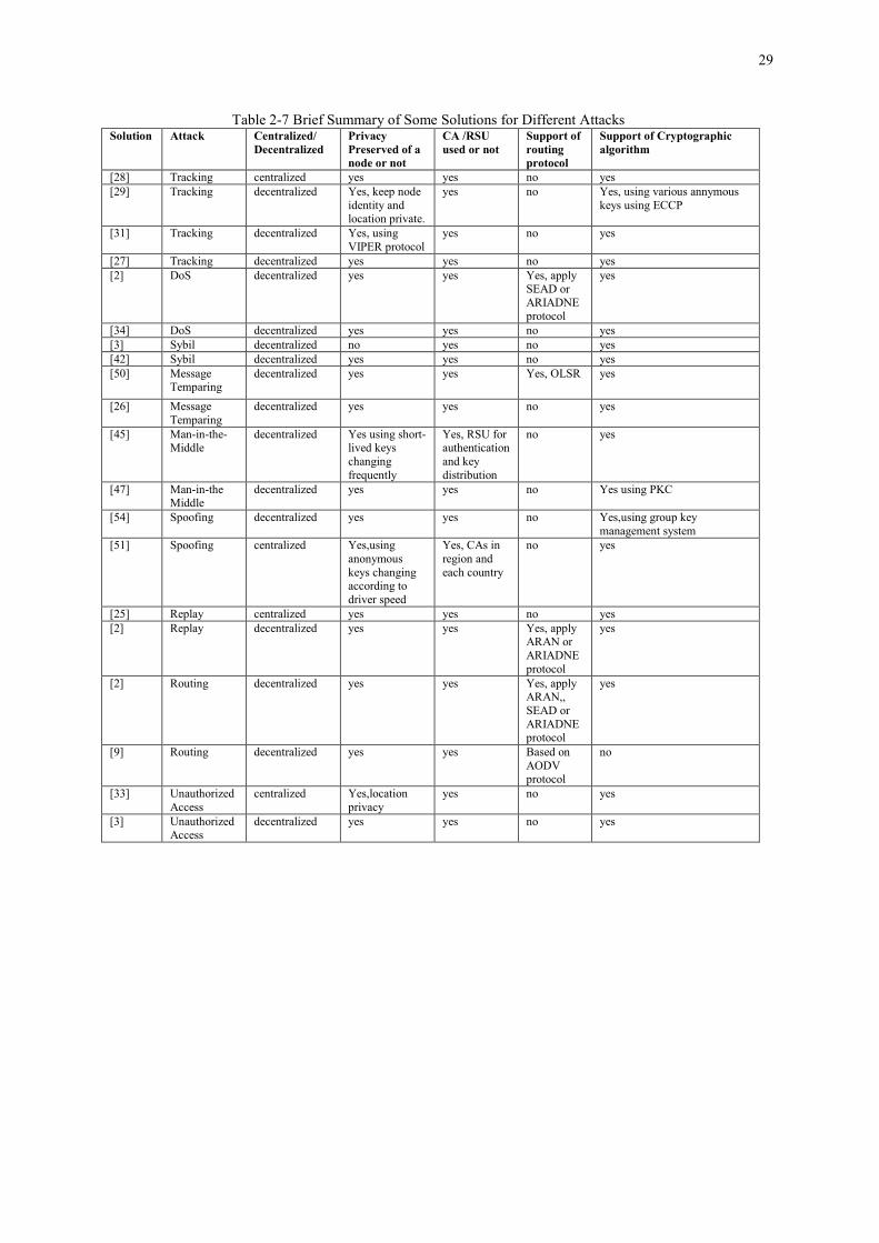
Table 2-7 Brief Summary of Some Solutions for Different Attacks Solution Attack Centralized/
[9] Routing decentralized yes yes Based on AODV protocol
no
[33] Unauthorized Access
centralized Yes,location privacy
yes no yes
[3] Unauthorized Access
decentralized yes yes no yes
30
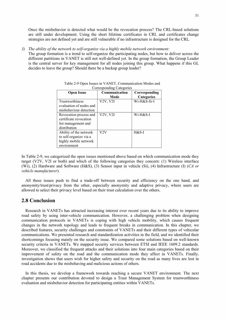
2.7 Summary and Discussion
Based on the security approaches presented in Subsection 2.3.2, the researchers in VANET tried to bypass many constraints or vulnerabilities attacking the vehicular network. Although many issues are still open for further research, we highlight below some of those that will be investigated in our framework: 1) The trustworthiness evaluation of nodes participating in VANET and their misbehavior detection: Evaluating the trustworthiness of a vehicle in VANET is an open problem. We previously mentioned that any defection in the communication and/or messages by a malicious vehicle endangered people's lives. Therefore, certain criteria should be defined to evaluate the trustworthiness of a node. Moreover, based on this evaluation, special criteria should be set to filter out the misbehavior either at the vehicle or at the backend to limit the effect of the malicious nodes.
2) The revocation process and the certificate revocation list management and distribution:
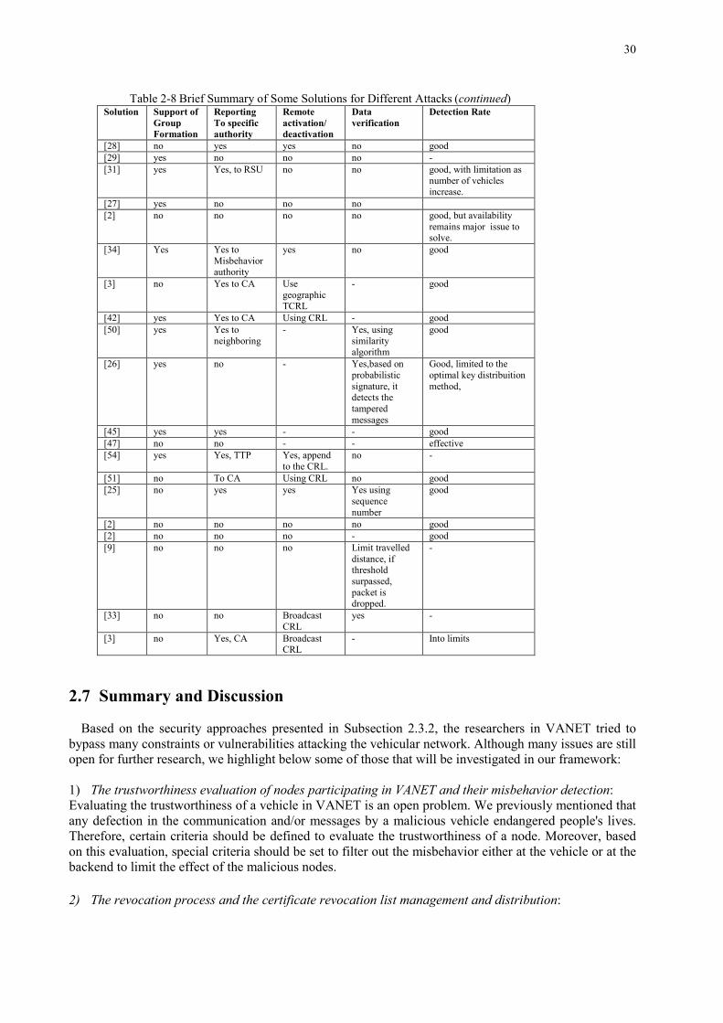
Table 2-8 Brief Summary of Some Solutions for Different Attacks (continued) Solution Support of
Group Formation
Reporting To specific authority
Remote activation/ deactivation
Data verification
Detection Rate
[28] no yes yes no good [29] yes no no no - [31] yes Yes, to RSU no no good, with limitation as
number of vehicles increase.
[27] yes no no no [2] no no no no good, but availability
remains major issue to solve.
[34] Yes Yes to Misbehavior authority
yes no good
[3] no Yes to CA Use geographic TCRL
- good
[42] yes Yes to CA Using CRL - good [50] yes Yes to
neighboring - Yes, using
similarity algorithm
good
[26] yes no - Yes,based on probabilistic signature, it detects the tampered messages
Good, limited to the optimal key distribuition method,
[45] yes yes - - good [47] no no - - effective [54] yes Yes, TTP Yes, append
to the CRL. no -
[51] no To CA Using CRL no good [25] no yes yes Yes using
sequence number
good
[2] no no no no good [2] no no no - good [9] no no no Limit travelled
distance, if threshold surpassed, packet is dropped.
-
[33] no no Broadcast CRL
yes -
[3] no Yes, CA Broadcast CRL
- Into limits
31
Once the misbehavior is detected what would be the revocation process? The CRL-based solutions are still under development. Using the short lifetime certificates in CRL and certificates change strategies are not defined yet and are still vulnerable if no infrastructure is designed for the CRL.
3) The ability of the network to self-organize via a highly mobile network environment:
The group formation is a trend to self-organize the participating nodes, but how to deliver across the different partitions in VANET is still not well-defined yet. In the group formation, the Group Leader is the central server for key management for all nodes joining this group. What happens if this GL decides to leave the group? Should there be a backup group leader?
In Table 2-9, we categorized the open issues mentioned above based on which communication mode they target (V2V, V2I or both) and which of the following categories they concern: (1) Wireless interface (Wi), (2) Hardware and Software (H&S), (3) Sensor input in vehicle (Si), (4) Infrastructure (I) (CA or vehicle manufacturer).
All these issues push to find a trade-off between security and efficiency on the one hand, and
anonymity/trust/privacy from the other, especially anonymity and adaptive privacy, where users are allowed to select their privacy level based on their trust calculation over the others.
2.8 Conclusion
Research in VANETs has attracted increasing interest over recent years due to its ability to improve
road safety by using inter-vehicle communication. However, a challenging problem when designing communication protocols in VANETs is coping with high vehicle mobility, which causes frequent changes in the network topology and leads to frequent breaks in communication. In this chapter, we described features, security challenges and constraints of VANETs and their different types of vehicular communications. We presented research and standardization activities in the field, and we identified their shortcomings focusing mainly on the security issue. We compared some solutions based on well-known security criteria in VANETs. We mapped security services between ETSI and IEEE 1609.2 standards. Moreover, we classified the frequent attacks and their solutions into four main categories based on their improvement of safety on the road and the communication mode they affect in VANETs. Finally, investigation shows that users wish for higher safety and security on the road as many lives are lost in road accidents due to the misbehaving and malicious actions of others.
In this thesis, we develop a framework towards reaching a secure VANET environment. The next
chapter presents our contribution devoted to design a Trust Management System for trustworthiness evaluation and misbehavior detection for participating entities within VANETs.
Table 2-9 Open Issues in VANET, Communication Modes and Corresponding Categories
Open Issue Communication Mode
Corresponding Categories
Trustworthiness evaluation of nodes and misbehaviour detection
V2V, V2I Wi-H&S-Si-I
Revocation process and certificate revocation list management and distribution
V2V, V2I Wi-H&S-I
Ability of the network to self-organize via a highly mobile network environment
V2V H&S-I
32
33
Part II: Trust Management System
34
35
Chapter 3
The Hybrid Trust Model (HTM)
3.1 Summary
After exploring state of the art in Chapter 2, one of the challenges arises within the vehicular network is to evaluate the trustworthiness of participating vehicles. We start by defining the trust in VANET, then the trustworthiness problem statement, with an overview of the different existing Trust Model solutions within the literature and gap analysis between them. Afterward, we expose our proposed solution, the Hybrid Trust Model (HTM) within a modular and secure infrastructure. Then we detail the group-based V2V authentication and consider the Group Leader-based communications. We describe the model behavior while preserving privacy and maintaining low network overhead. Using different metrics, this model introduces a novel formulation for trust calculation within vehicles, Group Leaders and at the Infrastructure levels. Based on this trust model, Misbehavior Detection Systems are proposed within vehicles and GLs to classify vehicles and to activate the revocation process through notifications sent to the Misbehavior Authority (MA). The MA takes specific actions to maintain the network stability as long as possible. 3.2 Introduction
Security is one of the main concerns in VANETs, and trust is a key element of security that prevents
generic attacks on the network [34] [115]. The trust value is used to measure the belief between two entities (the truster and the trustee). Its value allows us to determine if we can trust the trustee or not (related to a situation and a time).
The trust evaluation plays a vital role in the security and quality of a VANET since this latter is based
on data exchange (safety/non-safety applications) among vehicles. Vehicles can behave selfishly or maliciously for individual benefits. They can falsify or alter the exchanged safety messages which endanger people’s life [129].
Trusting a malicious node can lead to unpredicted threats, like affecting the network efficiency, large
consumption of resources and exposure to attacks. Especially, if this malicious node is the Group Leader (GL) which has a crucial role within the group; it is responsible for group keys generation and distribution based on group members’ activities. This issue implies that the GL must be the most trustworthy vehicle to accomplish these objectives. Throughout the literature, group formation enhances vehicular safety in VANETs [16] [59], [128], [134] [135]. It is a valid strategy to strengthen privacy, to provide authentication, and to limit the unauthorized access. The group-based authentication reduces the communication with the infrastructure. Through group signature, it ensures integrity, non-repudiation, confidentiality, and anonymity. Therefore, using a trust evaluation technique becomes a must to ensure a safe and secure driving environment in VANETs. Thus allowing vehicular sensing networks (VSNs) in smart cities to benefit from VANET secure V2V and V2I communications, to transmit and integrate reliable and important information related to a city’s operation [130].
Different families of trust evaluation approaches exist [48] [73], [81], [118], [129], [136], [137]: policy-
based approach, monitoring based approach, and the hybrid approach. In the Policy approach, it allows expressing the different attributes, the actions to perform and the different conditions to establish trust. Monitoring approach evaluates the trust level of an entity based on monitoring solutions. It can be
36
calculated with different strategies: either direct or indirect evaluation. The direct calculation is based on the exchange of attributes or combined parameters in P2P (Peer-to-Peer) networks. The indirect calculation (or reputation) is based on the feedback of the different entities participating in the model. Finally, the Hybrid approach aims to combine both to evaluate the trust. All these models are based on two types of architectures: centralized or decentralized frameworks. For the centralized, a central node will be delegated to monitor all communications, analyze the historical data and evaluate the trust level. While for the decentralized, each node can have the role of a truster and a trustee. Each one may evaluate the trust level of any other entity. A trusted module has to be installed then in each node. Figure 3-1 illustrates the different trust evaluation approaches mentioned above.
Figure 3-1 Different Trust Evaluation Approaches
In this chapter, we focus on the trustworthiness evaluation of vehicles participating in VANET and their misbehavior detection within groups. Vehicles will organize themselves into groups where a Group Leader manages each group. The GL can communicate directly with the members of its group, i.e., vehicles are located within its radio range. Notice that vehicles may belong to more than one group; in that case, they can play a relay role and allow multi-hop communication between different groups. The most critical issues to be resolved are: how to define the trust parameters and evaluate them, and how to combine the different evaluations and share feedbacks among participant vehicles. The proposed solution detailed in the coming sections will answer all these concerns. 3.3 Analysis of Existing Trust Solutions in VANETs
In this section, we review some existing schemes, observe their merits and limitations and compare
their choices. Many researchers investigated the Trust evaluation within VANETs [48], [62]- [82],�[114],�[116],�[118] using various techniques. For the trust computation, it can be either based on a direct calculation for predefined parameters between two communicating vehicles (sender and receiver), on an indirect calculation based on the neighboring opinion sent to the receiver about the sender for evaluation, or hybrid mode which is the combination of both direct/indirect. To evaluate the trust of a specific vehicle, the decision-making can be either centralized in an entity within the infrastructure, decentralized through participating vehicles or a combination of both centralized/distributed. For participation, it can be either proactive or reactive. Proactive means controlling a situation rather than responding to it, while reactive means the opposite. For the misbehavior detection scheme, it is broadly divided into two categories: data centric and non-data centric. The meaning of data centric is to believe
37
based on information rather than the source of information, e.g., detect misbehavior based on the collected information (e.g., beacons, alert message..). Otherwise, in some schemes, the misbehavior is detected by a Trusted Authority (TA) itself, which may require additional overhead and a long time for detection.
Trust establishment approaches can be divided into an infrastructure based trust or self-organizing based trust [48]. Within the infrastructure models [68]- [70], trust establishment relies on verifying certificates provided to vehicles, while in the self-organizing models [71] [72] the trust establishment is realized based on cooperation between vehicles. Infrastructure based trust can have either centralized or distributed decision-making management. Both models (infrastructure or self-organizing) can be either Entity or Data oriented. Entity oriented models maintain the trust of other nodes individually, i.e., no need for the third party. While Data oriented models are based on similarity mining technique used for identifying similar messages or similar vehicles [71]- [80]. Messages correlation or vehicles verification provides appropriate trust metrics values based on direct, indirect or hybrid calculation [81]. Trust metric values are used for nodes classification and establishment of a secure and reliable communication between them [74].
The privacy is better preserved in the self-organizing trust models [71], [72] than in the infrastructure ones; VANET users are anonymous within their groups in group-based VANET communications. The group members are anonymous for outsiders, i.e., only group managers (GLs) can trace their group members. Additionally, the self-organizing simplifies the process of building trust based on received messages. Thus provide better and more confident decisions for selecting the most appropriate GL by considering the trust value of vehicles from different participants.
The proposed solutions mentioned above [48], [62]- [82], [114], [116], [118] designed particularly for VANET partially cover the security requirements mentioned in [82]. Those requirements are Privacy, Adaptive to rapid network changes, Scalability, Realistic (real test scenarios), Low network overhead, Decentralization. Table 3-1 shows a comparison between the existing solutions based on the different techniques and characteristics mentioned above.
38
Some of the existing gaps in the previously proposed trust solutions are: i. in data oriented models, they deal more with the trustworthiness of the data received from other nodes rather than the nodes themselves. Trust is purely based on events disseminated by entities, and it needs to be established regardless of any prior interaction with these entities [68] [75]. ii.sometimes the evaluation of specific information could be tampered or unavailable when needed; attack detection techniques are missing, especially for sophisticated attacks such as “Sybil attack”. A lack of a risk analysis for the proposed models [63] [74]. iii. in combined models, reputation relies on the existence of other peers that have enough knowledge and can be trusted. The absence of these peers will degrade the evaluation [75]. iv.network overhead is increased by continuous routing and security updates [78].
As a result, this triggers further research in this field for potential improvements to define a new framework for a trust model in VANETs. In this paper, we propose a Hybrid Trust Model (HTM) that covers the major security requirements mentioned in [82].
Table 3-2 compares our proposed model to some existent trust evaluation and misbehavior detection systems based on a list of criteria. We define this list to highlight the ability of these systems to evaluate the trustworthiness of participating nodes in a rapidly changing network with the possibility of several frequent attacks, preserving the privacy of the participants and with low network overhead. The authors in [114] [115] analyze the probabilistic and deterministic approaches (individually and combined) to estimate trust for VANET security. The probabilistic approach determines the trust level of the peer vehicles based on received information. The deterministic approach measures the trust level of the received message by using distances calculated using received signal strength (RSS) and the vehicle’s
Table 3-1 Comparison between Different Trust Models
geolocation (position coordinate). A combination of the probabilistic and deterministic approaches gives better results compared to individual approaches. [116] propose an algorithm DMN (Detection of Malicious Nodes) in VANETs improves DMV (Detection Malicious Vehicle) Algorithm regarding the adequate selection of verifiers for detection of malicious nodes and hence improves the network performance. The comparison in Table 3-2 shows the efficiency of our proposed model that we will detail in the next section.
Table 3-2 Comparison of Trust Evaluation and Misbehavior Detection Models
Solution Low Network Overhead
Real-time Processing
Robustness/ Security
Privacy Decentralized Short-lived Association
Misbehavior Detection
Our Proposed Model
x x x x x x x
[114] x x x [115] x x x [116] x x x x
3.4 Proposed Hybrid Trust Model
We propose a Hybrid Trust Model (HTM) to evaluate vehicles’ behaviors and estimate their corresponding trust metric values. HTM serves to judge vehicles trustworthiness and reports to Misbehavior Authority (MA) which takes appropriate actions to deactivate the malicious node. The node with highest trust metric value will be a potential GL for its neighboring vehicles. The architecture of this Trust Model is based on a secure, modular and distributed PKI architecture adopted by NHTSA (National Highway Traffic System Administration) [12], and on group formation and GL-based communication [85]. We adopt the NHTSA architecture and the group-formation to benefit from several security advantages detailed in the following subsections.
This HTM model involves a monitoring system processing based on the cooperation between vehicles and the validity of their broadcasted data. It is a continuously and dynamically monitoring process changing at each received values of monitoring. HTM provides a secure environment that can mitigate the potential attacks or minimize their duration on VANETs. The cooperation within the Trust Model is a combination of centralized and distributed entities which aims to preserve participants’ privacy and tries to maintain low network overhead. For each node, the Trust metric is based on direct and indirect calculation, transmitted to the nearest GL which transfers all trust metrics to the back-end system through the nearest RSU. RSUs are widespread on the roadside to fulfill specific services to the back-end system. One of these services is relaying information between OBUs and the back-end system and vice-versa. However, in the absence of RSU in range, OBUs may relay information in a multi-hop V2V scenario to reach an RSU. In the back-end system, the Certificate Authority (CA) will compute a global trust metric for each participating node. At different stages, the trust metric has a threshold when exceeded a node is considered trustworthy; otherwise, a proposed set of rules is used to filter out the malicious ones. Thus our proposed model is based on a hybrid trust approach, e.g., a combination of monitoring and policy-based approaches.
Basic entities of the model architecture and the group formation are detailed in the coming subsections. A Risk Analysis for the proposed trust model is detailed in Chapter 4.
3.4.1 Architecture The reference model of the HTM architecture and its components is briefly described in Figure 3-2
below. The proposed HTM is composed mainly of two parts: A) back-end system and B) vehicular groups. Part ‘A’ corresponds to NHTSA architecture. Its main entities are classified based on their functionalities into four groups. These groups are policing (SCMS Manager), certificate processing, communication with vehicles and Misbehavior Detection/Revocation. Part B is composed of groups of
−
−
−
−
41
Many attackers can compromise the security of this infrastructure, the vehicles, the data exchanged
between vehicles or the infrastructure, and the communication between different parties in VANETs [12]. Thus, the grouping and its special cryptographic mechanism combined with the NHTSA entities ensure that this model architecture will mitigate the risks of these attacks [34].
3.4.2 Grouping
There are many ways to form groups in VANET applications. For example, all public transport buses
can be members of a preset group. It is the easiest and most efficient way of group formation, but it requires prior knowledge of all group members, as well as a common authority over them. But it is not the case when individual drivers on a highway decide to join a group to improve their driving experience. It requires on-the-fly group formation where a group leader is elected, and group membership is managed dynamically. This latter category of groups is the most useful due to its flexibility, but it is also challenging mainly for group leader election and groups overlapping.
A group is formed when there are at least two vehicles within their radio range on the road. A group is composed of the vehicles in a zone of 300m of radio range around the moving GL. At the initialization, if there is no vehicle in the immediate neighborhood of v1, then v1 the first vehicle that authenticates in time to the back-end system through the RSU in a certain zone will be elected as the GL. The second vehicle that authenticates to the back-end system in the same zone will be elected as Potential Group Leader (PGL), i.e., it can be considered as backup for this GL. Later on, it will depend on vehicles behavior (trust metric values) on the road to elect the GL; the vehicle with the highest trust metric value in a group will be considered as potential GL. In case of departure of the GL, we consider two scenarios: i. GL decides to leave the group near an exit point; ii.GL is out of coverage. In the first scenario, the GL informs the back-end system through the RSU about its departure; the back-end system will delegate the GL responsibilities to the PGL, the new GL candidate in its group. At that time, the group will be reformed. It happens that not all vehicles handled by the outgoing GL are in the radio range of the PGL. Those vehicles will try to join another group. In the second scenario, the vehicles members of its group will detect its absence by not receiving periodical beacons from it every 100ms. They remove it from their neighbors’ table after a period of 200ms and try to join another group. Every elected GL defines a group id (GID) and broadcasts it to neighboring vehicles. The CA assigns to each group member a unique ID for non-repudiation purpose. Vehicles are required to use group keys to communicate within a group. The key generation process depends on the schema type we have: either static, e.g., the number of group members is assumed to be fixed or dynamic, e.g., the prospective number of group members is unknown [138]. We have on-the-fly group formation which represents a dynamic schema. For the key generation process, the GL generates its own private key PrGL, the public key of the group Pugr [138] and the symmetric key for the group Kgr. PrGL is used to issue membership certificates to the prospective group members. Pugr is used to identify group members. Kgr is used to encrypt confidential data between group members, e.g., the trust metric values of neighboring vehicles. We use the symmetric encryption because it is less consumption of resources and minimizes the delays due to the asymmetric ones [16] [17]. Additionally, The GL periodically changes these keys without returning to the CA. Upon the group formation, the GL broadcasts the following keys for all vehicles within its group: the symmetric group key (Kgr) encrypted with each vehicle public key Pui, the public key of the group (Pugr) encrypted with the symmetric group key (Kgr) and signed with the GL private key.
42
The GL broadcasts the symmetric group key (Kgr) and the public key of the group (Pugr) to any group member as follow:
In case of any entry to a group, the GL verifies the new vehicle and gives it its secret signing key Prsk, Pugr, and Kgr of the group. Upon exit from a group, the GL updates the group members with new Pugr and new Kgr. The investigated scenario is as follows: on a highway, groups are formed with vehicles traveling in the same direction as illustrated in Figure 3-3. The group presents a geographical area of 300 meters around the vehicles traveling in a cooperative driving. Depending on the country, the regulations set the maximum speed on the road. On a highway, we can estimate that the vehicles have an average speed with small velocity variation. As we are within the area, there is no need to communicate with the infrastructure. To keep in touch, the vehicles broadcast "Here I Am" messages (beacons or basic safety messages in IEEE standard) to refresh their adherence and position within the group. A user with a key pair of public and private keys can apply the signature generation algorithm to produce a digital signature on some message. The digital signature ensures the authenticity of the signer based on asymmetric or public-key cryptography. It involves a signer and potentially many verifiers and stands in conflict with privacy. For group communication, we use group signature scheme that ensures authentication with privacy. Users can authenticate themselves on behalf of a group, rather than on individual basis. The group signature incorporates multiple secret private keys with one group public key. The generation of secret signing keys is during the join process of the prospective group members to a group. The admitted group member receives its secret signing key from the GL whereas the GL obtains some (secret) information used later to broke the anonymity of the new member in case of any misbehaving.
Vehicles periodically broadcast signed beacons to neighbors. Each includes the short-term certificate of the sender in its header and its digital signature in the trailer. The attached certificate ensures trust in the system while the signature is used for verifying the integrity of the beacon’s content. The short-term certificate includes a validity period, the public key of the sender and the digital signature of the authority that issued this certificate. The digital signature is generated by creating a hash of the beacon content and the timestamp using SHA-256, and inputting the hashed content to the Elliptic Curve Digital Signature Algorithm (ECDSA). For every exchange, a vehicle needs to verify the sender if it is not already verified, checks if its certificate is still valid and not revoked, and then verify its signature. The verification of its
Figure 3-3 Vehicular Groups on Highway
43
identity consists of verifying its certificate, i.e., confirms that the digital signature on the certificate included in the beacon is digitally signed by the CA that issued it to the sender. The receiving device should already have a copy of the authorizing certificate for the authority stored onboard. In case it does not, it requests the authorizing certificate from the sending device (Peer-to-Peer certificate distribution). This process is repeated for any number of CAs up to the root CA, which authorizes the entire system. For the validity of a certificate, it consists of checking the validity period then its presence on the Certificate Revocation List (CRL) detailed in Chapter 5. For the verification process of the digital signature, the sender public key in the attached certificate is used to reverse the signature process, i.e., take the encoded string, decode it with the sender public key, generate the original string and then compare with the sending device information.
When an accident happens in the area, the vehicle itself or the nearest neighbor to the origin of the accident disseminates an emergency message. This message is signed with the vehicle secret signing key and concatenated with vehicle neighboring direct trust values (detailed in the following sections). The inter-vehicles-groups will route the alert messages and secure them across the other groups and thus ensures the multi-hop communication. Following the collaborative driving per and between groups, the dissemination of an alert message between two vehicles X and Y within the same group is as follows: At X: the alert message (Msg) includes the group public key Pugr in the attached certificate. It is signed by the private signing key of X Prsk(X) then concatenated with (DT) encrypted by the group symmetric encryption key Kgr as follow: X→ Y: {(Msg) SigPrsk ||(DT)Kgr [(Msg) SigPrsk || {DT} Kgr ]} Where DT is a vector, including direct trust values, (Td), for all vehicles neighbors of vehicle X. At Y: Through the group public key Pugr, Y verifies X, it decrypts the confidential data with the group symmetric key Kgr and reads the alert message. Figure 3-4 illustrates the dissemination process of an alert message between members of the same group.
Without group formation, the receiving vehicle will verify the certificate of each neighbor and its digital signature using the public key of the issuing CA and the public key of the sender. This procedure produces a delay in the communication process and sometimes overhead over the network (in case of absence of the authorizing certificate on board of the receiving device). With the group formation, all group members are using the group certificate, and the same public key of the group (Pugr) to verify any signature generated by the group signing key of any group member. This procedure will reduce the delay and overhead of the certificate and digital signature verification and ensure the anonymity of the group members [16].
Figure 3-4 Alert Message Dissemination Process within the Same Group
44
As a recall from the introduction, the GL has a crucial role within its group. This implies that GL must be the most trustworthy vehicle to accomplish these objectives. However, there is still the issue of inserting a fake GL which triggers us to design a Trust Model to evaluate the trustworthiness of participant vehicles within VANET and select the most trustworthy as potential GL. After presenting the model architecture, we describe in the next section the model work cycle.
3.4.3 Hybrid Trust Model Work Cycle
Consider a group of vehicles in Figure 3-5 within a geographical area of 300 meters radius circulating in a cooperative driving. Each vehicle v monitors all its 1-hop neighbors.
Notation. For trust evaluation, we will use the following notations in Table 3-3:
A new vehicle i with public Pu and private Pr keys at the Department Motor Vehicles (DMV) will enroll in the back-end system through the Device Configuration Manager (DCM) before entering the vehicular networks. The DCM plays a role in the bootstrap process by ensuring that a device is cleared to receive its enrollment certificate from the Enrolment Certificate Authority (ECA) and it also provides a secure channel to the ECA. Vehicle i will get successively its long-term certificate from ECA and its initial trust value, Tglob(i)0 = 0.5 (which means vehicle i is a vehicle neither honest nor malicious). This initial global trust value is modified following its behavior on the road. NHTSA has suggested that this bootstrapping function need to take place at the time of OBU manufacture to facilitate the identification of defective equipment [89].
Figure 3-5 Vehicular Groups
Table 3-3 Notation for Trust Evaluation
Notation Description Tdv(i) “Direct Trust”, which evaluates the judgment of vehicle v on any vehicle i = direct
observation. Trv(i) “Indirect Trust”, which evaluates the judgment of vehicle v on vehicle i based on v’
neighborhood opinions = other peer recommendation. Ttotv(i) “Total Trust” of vehicle i calculated by vehicle v. It is based on a combination of
direct and indirect Trust. Tglob(i)0 Initial “Global Trust” of vehicle i given by the back-end system through the DCM
for newly vehicles entering VANET. It is initialized to 0.5, i.e., the newly entered vehicle is considered as an intermediate one, neither honest, nor malicious. This initial global trust will be updated based on vehicle i behavior in VANET.
Tglob(i) “Global Trust” of vehicle i stored in the infrastructure. It represents the updated global trust of vehicle i stored within the infrastructure database.
45
Then vehicle i requests its short-term certificates used for privacy preservation within VANETs. This certificate request is signed using the private key corresponding to the public key of the long-term enrollment certificate. This process is done either at the vehicle dealers’ locations or gas stations via a new entity named short-term Certificate Issuer Proxy (sh-tCIP). Once the back-end system verifies its digital signature, e.g., the request is coming from a valid device. Vehicle i will have Pui, Pri associated with the long-term enrollment certificate and a bunch of short-term certificates changing every 5 minutes. The short-term certificates are used by a vehicle’s OBU to verify the sender and validate sent and received basic safety messages in VANETs and later on for signing misbehavior report in case of detection of any malicious behavior. Also, the short-term certificates are known as pseudonym certificates (authorization tickets for ETSI [13]). They contain no information about users to protect privacy and avoid tracking. They serve as authorization credentials that permit users to participate in the vehicular network. Once this step is achieved the vehicle i has to join a group of vehicles. It will broadcast signed beacons with its private key corresponding to the public key in the short-term certificates. Beacons are periodical messages broadcasted between vehicles every 100ms and used to inform neighbors about vehicle position, direction, velocity…The nearest GL verifies vehicle i, and then it gets its secret signing key Prsk, the public key of this group Pugr used for asymmetric group signature and the symmetric key of the group Kgr used to encrypt confidential data between group members. It happens that a vehicle i receives the choice to join several groups; it will launch the join process with their GLs. After verification of vehicle i within the GL on-board unit, vehicle i will get different secret signing keys and different public group keys from GLs in the different groups for groups’ signature. Vehicle i will act as a relay between those different groups. A broadcasted alert signed by a member of group1 will be received by vehicle i which in turns will sign it by its different secret signing keys received from different GLs and thus the message will be broadcasted via vehicle i to different groups. Figure 3-6 shows the enrolment and join to group process of a vehicle i within the Hybrid Trust Model.
The neighboring vehicles receiving vehicle i signed beacons use the corresponding public key of the group to verify i, add it to their neighborhood table and record its information in their database. Beacon is usually issued every 100ms, a checker every 2x100ms will update the neighbors’ table about the vehicle status if (alive or not) and remove stale entries to a history table. We define 200ms to remove a neighbor
Figure 3-6 Enrollment and Join to Group Process of Vehicle i within the Trust Model
46
from neighbors’ table because we tolerate missing at least one beacon from it otherwise it will not be considered in the neighbors’ radio range. Table 3-4 illustrates the structure of neighbors table.
Each vehicle in the group must monitor all the trust metric parameters. Certain parameters are related to the communication, others are related to the transmission/reception of a vehicle, some parameters are given by the Global Positioning System (GPS) or sensors, and others are based on variables calculation. Such metrics can be categorized into: critical, intermediate and optional. Figure 3-7 illustrates the monitoring process of vehicle i on its neighbors. A vehicle i enters a certain area, after joining the group. It will broadcast and receive beacons from neighbors. The gathered information is stored in the Event Data Recorder (EDR) of the vehicle i, and the computation process of the trust evaluation will take place. Without loss of generality, all vehicles within the network monitor each other to undertake the trust evaluation detailed in next section.
Based on these parameters, the calculation of the trust metric of each vehicle is done as detailed below in the coming sections. This trust metric has a lifetime (200ms) which is an essential indicator in a rapidly changing topology (VANET) because it reflects the connection status. No need to keep the outdated trust metric of a specific vehicle that is not my neighbor anymore.
Vehicles within VANETs can disseminate two kinds of messages: safety messages and certificate exchange messages [12]. Safety messages are used to support safety applications. Certificate exchange messages ensure that the transmitted messages are from the trusted source. Safety messages include information about the vehicle’s behavior. SAE J2735 [127] defines the design specifications for the safety messages. The Basic Safety Message (BSM) is divided into two parts: Part I has priority and is transmitted more often, and BSM Part II contains a set of data elements that can vary and are broadcasted only when an event happens. Then Part II is appended to Part I data and broadcasted [86]. Beacons are the BSM part I; alert messages (emergency or warning) are BSM part I concatenated with BSM part II.
Table 3-4 Neighbors table
Neighbor ID Contact Time Status
(Pseudo-ID, for privacy)
Time for first beacon message
GL, or normal participant.
Figure 3-7 Monitoring Process of Vehicle i
47
Emergency messages are like ‘Vehicle Crash,’ ‘Vehicle on Fire,’ ‘Vehicle out of Control’… while warning messages are like ‘Ice Ahead,’ ‘Emergency Vehicle is Coming,’ ‘Road Closed Ahead’…. BSM also needs certain preliminary elements that help a receiving device to know what it is receiving. Those elements are Message-ID, Message count and Temporary ID [90]. Message ID represents the different types of messages defined by SAE Standard J2735 and sent over DSRC; if it is equal 2, i.e., it is a Basic Safety Message. Message count represents a number in sequence from 0 to 127 assigned to the sent BSM. It helps the receiving vehicle to appropriately put the messages in order and be aware of any missing messages from the sender. Temporary ID is of four-byte string array randomly-generated number that allows a receiving device to associate messages sent from the same device together without knowing the real identity of the sender. This temporary ID is changed to every five minutes when the BSM short-term certificate changes. Having the temporary ID and the certificate change at the same time reduces some of the risk to track a device. In our model, we use this field for vehicle pseudo-ID.
Each disseminated message includes a short-term certificate in the message header and the signature of the vehicle in the message trailer as illustrated in Figure 3-8. The short-term certificate is a must for user verification. It also ensures user privacy and anonymity. The signature is used to believe that the message is created by a known sender (authentication), that the sender cannot deny having sent the message (non-repudiation), and that the message is not altered in transit (integrity) within the vehicular network [59].
A certificate (as detailed later in Chapter 5) has a validity period and a length that reaches 120 bytes. So inclusion frequency of short-term certificate into messages is limited due to the channel capacity and to limit the channel load. A sporadic inclusion of short-term certificate is suggested; ETSI proposed an inclusion frequency of 1Hz and IEEE of 2 Hz �[131]. In between, disseminated messages include the digest of the short-term certificate of 8 bytes length (HashedId8) �[60], this yields massive reduction in message size �[131]. Message verification requires knowledge of the full Short-term certificates. Hence, short-term certificates have to be buffered and looked up, when their digests are received later on. In case the full short-term certificate is unknown, the message is discarded, as it cannot be verified. After presenting the model work cycle, we will move to the next section to describe the trust computation process. 3.5 Trust Computation In this section, we present all the parameters involved in the Trust computation. Our Trust Model is based on direct observation and other peer recommendation. The direct observation is called direct Trust and based on evaluating data received directly from one hop, while the peer recommendation is called indirect Trust and based on forwarding evaluated data by a third party which is a neighbor in our case. The Trust computation is calculated in two cases:
Figure 3-8 Basic Safety Message Format
48
- Normal mode: is the case where only beacons (BSM part I) are broadcasted between vehicles, no emergency messages are circulating. Beacons are broadcasted between vehicles connected within one hop (within the same range) every 100 milliseconds.
- Event mode: is the case where an event happens (emergency or warning message broadcasts) - BSM part I and part II concatenated as described above in section �3.4.2.
In this model, all neighboring vehicles are supposed to monitor each other and participate in the calculation of the different trust metrics. For that, let us define the following:
3.5.1 Direct Trust Computation- Normal Mode
The beacon is composed of VID, current position, velocity, status. Where VID stands for vehicle’s pseudo identity, current position stands for its geographical position, velocity its vehicle driving velocity and status (operating mode: Ad-hoc mode...). The direct trust of a certain vehicle i calculated by a certain vehicle v is based on many parameters detailed below. These parameters are used in equation (�3-1) to reflect the vehicle behavior. Let us consider one of these k parameters ‘the velocity’ which measures the speed of a vehicle i. It is broadcasted in the beacon sent by vehicle i to its neighboring vehicle j. When j receives the beacon, it applies the following normalization criteria, which is also illustrated in Figure 3-9: - If the velocity of i >+25% of the road speed limit or if the velocity of i <-25% of the road speed limit,
then the trust metric mk reflecting the velocity will be 0.1.
- If the velocity of i is between -25% and -15% of road speed limit or if the velocity of i is between +15% and +25% of the road speed limit, then the trust metric mk reflecting the velocity will be 0.5.
- If the velocity of i is between -15% and -10% of road speed limit or if the velocity of i is between
+10% and +15% of the road speed limit, then the trust metric mk reflecting the velocity will be 0.7.
- If the velocity of i is between -10% and +10% of road speed limit, the trust metric mk reflecting the velocity will be 0.9.
The geometric mean is applied to the different parameters considered in this case; we use the geometric mean to calculate the direct trust. Referring to [108], a geometric mean is often used to take into account the simultaneous effects of the different parameters. Hence, the direct judgment on vehicle i, Td v(i) done by any other vehicle v, will be calculated based on the following equation:
(�3-1) Td v(i) = �∏ �������
��
Where αj is a weight factor and mj is the trust metric reflecting one of the many parameters: related to the communication and the transmission/reception of a vehicle, or given by the Global Positioning System
Figure 3-9 Normalization of Velocity Parameter for Direct Trust Calculation.
•
•
•
•
•
50
���(�): represents the direct trust of vehicle i calculated by neighboring vehicle j. It intervenes in the
calculation of indirect trust of vehicle v over vehicle i. 3.5.3 Total Trust Computation- Normal Mode
The total trust combines the direct and indirect trust for any vehicle. The total trust is calculated in three
steps at three levels: within vehicles, GL and Infrastructure (RSU). The total trust is used to evaluate the trustworthiness of a vehicle. 3.5.3.1 Vehicle Level
At vehicle level, the total trust of any vehicle i calculated by vehicle v is given by the equation ( 3-3):
( 3-3) �����(�) = � ∗ ���(�) +( − �) ∗ �!�(�) Where 0.5<ß<1, this could be justified by the fact that we considerably trust the direct calculation and we will not neglect the neighboring opinions referred to as the indirect calculation. Therefore, every vehicle v will fill its database with the values of the direct , indirect and total trust of all neighboring vehicles i as shown in Table 3-5. i varies from 1 to n. Where n represents the number of v neighbors.
Within each vehicle, old values within the trust database are updated iteratively following the smoothing move procedure in the following equation: ( 3-4) New value= α*new value + (1-α)*old value Where 0.5<α <1, which means we use a smoothing update procedure and not overwriting old values. We consider this range since we are more interested in the recently calculated values. The total trust list in Table 3-5 is used for vehicle trustworthiness evaluation within the vehicles’ control process (detailed later in Subsection 3.6.2). Finally, every vehicle v periodically (each 150ms) sends its neighboring vehicles’ total trust list Ttotv(i) to the GL which in turn computes the average total trust for vehicles within its radio range.
3.5.3.2 Group Leader Level At the GL Level, the average Total Trust for vehicle i calculated by a GL is given by equation ( 3-5):
( 3-5) Ttotm(i) =∑ �"#"
� (�)$�%
$
Where i: is any vehicle within the GL radio range.
Table 3-5 Trust Database of Vehicle v
Vehicle Tdv(i) Trv(i) Ttotv(i)
i Direct trust calculated by v
Indirect trust calculated by v
Total Trust calculated by v
51
n: is the number of occurrence of vehicle i Total Trust within the GL database. �&'&� (�) : is the Total Trust of vehicle i calculated by vehicle j.
Moreover, the GL periodically sorts its trust list in descending order thus the most trustworthy vehicle is on the top of the list. We consider that even if the GL was not the top list member, no changes in the GL election until the current GL leaves the group. Each time, the GL is passing by an RSU, it transfers the updated Total Trust of any vehicle i, Ttotm(i) only. RSUs within the same region are interconnected together, and with the infrastructure thus the updates are synchronized between RSUs and different entities of the infrastructure. These vehicles’ average total trusts, Ttotm(i), participate in the selection process of the potential GL in coordination with the back-end system (CA, RA, MA, LOP). Therefore, once the GL decides to leave the group, the first vehicle on the top of the list (the one with the highest Ttotm score) will be a potential GL candidate. This vehicle is called Potential Group Leader (PGL). Once the GL decides to leave the group, it will hand over its responsibility of the group to the PGL through the back-end system. The PGL (as new GL) will then regenerate group keys for encryption and signature and broadcast them to its group members. In case of departure of the GL, we consider two scenarios: i. GL decides to leave the group near an exit point; ii.GL is out of coverage. In the first scenario, the GL informs the back-end system through the RSU about its departure and all the vehicles within its radio range including the PGL via a broadcast message of type GL-Leave signed by the GL private key, PrGL. The GL-leave message format is similar to the Basic Safety Message (BSM) format detailed previously in Figure 3-8 with slight modification. GL-Leave message format = [BSM part I (Beacon) || PGL ID]SigPrGL. Where BSM part I includes vehicle details as vehicle pseudo-id, vehicle position, vehicle velocity…and PGL ID is the pseudo-id of the potential GL, the vehicle with the highest trust metric value within the outgoing GL database. Once receiving the leave message from the GL, the back-end system will check if the PGL is an honest vehicle, i.e., it is not on the black or grey lists. Then it will delegate the GL responsibilities to the PGL by sending it a signed PGL-delegation message from the Registration Authority RA. While vehicles members of the old group will discard the received messages signed by the old group’s credentials. PGL-delegation message format = [BSM part I (Beacon) || New group ID]PrRA. The PGL elected will act as new GL; it will form its group. It will regenerate a new group public key and a new symmetric key for the encryption. The new GL sends an an announcement of joining its group to all vehicles within its radio range. Vehicles from the old group and within PGL radio range will start the join to group process detailed previously in section 3.4.2. It happens that not all vehicles handled by the outgoing GL are in the radio range of the PGL. Those vehicles will try to join another group. In the second scenario, the vehicles members of its group will detect its absence by not receiving periodical beacons from it every 100ms. They remove it from their neighbors’ table after a period of 200ms and try to join another group.
52
3.5.3.3 Infrastructure(RSU) Level At the Infrastructure level, two cases occur for the global trust computation of any vehicle i, Tglob(i): - When vehicle i belongs to one group only, then its global trust Tglob(i) is equal to its average total
trust Ttotm(i) calculated by one GL. So Tglob(i) = Ttotm(i).
- When vehicle i belongs to several groups, then the RSU calculates the geometric mean of the Ttotm(i) received for this vehicle i as in equation ( 3-6). (e.g., if i belongs to two groups then its Ttotm(i) will be calculated by two GLs).
(�3-6) Tglob(i)=(∏ ��
�� �#"� (�))/�
N: number of groups to which vehicle i belongs.
The back-end system (Infrastructure-RSU) as a big data-center will merge and update these trust metrics using the smoothing update procedure mentioned in equation (�3-4) above and result in a global trust metric for each vehicle. This global trust metric Tglob(i) is used for vehicle evaluation, results classification and then deactivation of malicious ones. More details about vehicle behavior evaluation are expanded in the next section. Figure 3-10 summarizes the handover process of the different trust metrics calculated between the vehicles, GLs and the infrastructure.
To mention that, the initial global trust value Tglob(i)0 = 0.5 is given to any vehicle i entering the first time to the vehicular network. Afterward, its global trust Tglob(i) is updated based on its behavior on the road.
It happens that the back-end system does not receive a trust metric update of a certain vehicle i for a while. Many cases are considered:
- On the same day, we did not receive an update from vehicle i for a period greater than five minutes. Then the back-end system considers vehicle i as a parked car. Whenever vehicle i resumes its activity again, the back-end system will update its latest global trust value stored at the back-end system based on equation (�3-4).
- Within the same week, if the back-end system did not receive an update from vehicle i for a period less than seven days, then the back-end system will consider i as a parked car. Whenever
Figure 3-10 The Handover Process of the Calculated Trust Values between Vehicles, GLs, RSU, and the Infrastructure.
•
•
•
•
54
We will move to the next section to evaluate the vehicle behavior within the vehicular networks.
3.6 Evaluating Vehicle Behavior
The trust metric values of a certain vehicle in its different stages have a certain threshold whenever exceeded the vehicle is considered trustworthy. Otherwise, a simple set of rules is used to filter out the malicious ones. We consider that each vehicle (including GL – the vehicle with the highest confidence score) controls and sends its report directly to the Misbehavior Authority (MA) [12] [85]. The MA generates the final decision related to trustworthiness in our proposed model. Moreover, we propose a cooperation between vehicles and GLs in the control process. Since sometimes there are some attacks/attackers that can be detected by a vehicle and cannot be detected immediately by the GL.
In the following, we proceed by classifying vehicles between honest, intermediate and malicious. An honest vehicle represents a vehicle with good behavior. A malicious vehicle is a vehicle of bad behavior. An intermediate vehicle is a vehicle with doubtful behavior; it will be under inspection for a certain period (between 300ms and 5 minutes). If its misbehaving continues after the period expiry, then it will be considered as a malicious vehicle. Therefore:
- The GL controls and generates its report to MA.
- Every vehicle controls and notifies the GL which in turn notifies MA. If the GL is not reachable (neighboring vehicles are not receiving beacons from it within a period of 200ms), then the vehicle can directly notify the MA to take appropriate actions.
- MA analyzes the received data and takes appropriate actions. 3.6.1 Group Leader Controls
Based on equation (�3-5), each GL calculates Ttotm(i), the average total trust for each vehicle i within
its radio range. To compute the trust threshold Tthresh within the GL, we use the following equation:
Figure 3-11 Trust Evaluation Process in Event Mode
55
(�3-7) Tthresh =∑ �"#"�(�)$�%
$
Where n represents the number of vehicles within the GL database (number of vehicles already authenticated with the GL). i denotes any vehicle within the GL radio range. The arithmetic mean is used to calculate the average value of independent events [108]. Different total trust values of vehicle i calculated by different vehicles j are independent of each other. For that reason, we used the arithmetic mean in Tthresh calculation. A set of rules is used in each GL to classify every vehicle i within its radio range based on the following: If the average total trust of vehicle i, Ttotm(i), calculated by the GL exceeds its trust threshold (Tthresh) then vehicle i is considered an honest vehicle. Otherwise, if the average total trust of vehicle i, Ttotm(i), falls between (Tthresh)/2 and Tthresh, then vehicle i is considered an intermediate vehicle. The GL puts vehicle i under inspection for a specified period t; if t expires and vehicle i remains with its same behavior, then the GL considers vehicle i as a malicious one and notifies the MA. Differently, if the average total trust of vehicle i, Ttotm(i), is less than the half of the trust threshold value, (Tthresh)/2, then vehicle i is considered a malicious vehicle. The GL notifies the MA. This set of rules is also illustrated in Figure 3-12.
3.6.2 Vehicle-to-Vehicle Control
There is a difference in the evaluation process of vehicles behavior between normal and event mode. We introduce an accordance parameter that differs in both cases. The coming subsections 3.6.2.1 and 3.6.2.2 detail respectively the vehicle-to-vehicle control in normal and in event mode. 3.6.2.1 Vehicles Control – Normal Mode
A normal mode presents the case where only beacons are broadcasted between vehicles; no
emergency messages are circulating in the vehicular networks. In normal mode, we introduce a new
Figure 3-12 GL Trustworthiness Evaluation
56
parameter Av(i): “accordance parameter” of a vehicle v over vehicle i calculated in the following equation:
The accordance parameter Av(i) is the ratio of direct trust of vehicle i Td(i) calculated by vehicle v, over its indirect trust calculated by neighbors.
We also compute the trust threshold within each vehicle v as in equation ( 3-9): ( 3-9) Tthresh(v) = ∑ �"#"(�)
$�%
$
Where i varies from 1 to n. n represents the number of v neighbors. The accordance parameter Av(i), the trust threshold Tthresh(v) and the direct trust of vehicle i Tdv(i), are inputs for vehicle v to judge the trustworthiness of vehicle i. The set of rules used within each vehicle v to classify neighboring vehicle i consists of the following:
If the accordance parameter of vehicle v over vehicle i, Av(i), is 1, i.e., the judgment of vehicle v over vehicle i is similar to the feedback received from v’s neighbors regarding vehicle i. We consider the direct trust of vehicle v over vehicle i, Tdv(i), if it is greater than the trust threshold calculated within vehicle v, Tthresh(v), then vehicle i is considered an honest vehicle; otherwise, vehicle i is considered a malicious one. If the accordance parameter of vehicle v over vehicle i, Av(i), is greater than 1, i.e., the judgment of vehicle v over vehicle i is different from the feedback received from v’s neighbors regarding vehicle i. We consider the direct trust of vehicle v over vehicle i, Tdv(i), if it is greater than the trust threshold, Tthresh(v), then vehicle i is considered an honest vehicle; otherwise, vehicle i is considered an intermediate vehicle under inspection phase. If the accordance parameter of vehicle v over vehicle i, Av(i), is less than 1, i.e., the judgment of vehicle v over vehicle i is different from the feedback received from v’s neighbors regarding vehicle i. We consider the direct trust of vehicle v over vehicle i, Tdv(i), if it is greater than the trust threshold, Tthresh(v), then vehicle i is considered an intermediate vehicle under inspection; otherwise, vehicle i is considered a malicious one;
As mentioned before, the inspection period is used for monitoring intermediate vehicles. Its duration varies between 300ms to 5minutes. If this period expires and the misbehaving continues, vehicle v notifies the GL which in turn investigates and informs the MA. The set of rules within each vehicle v is also illustrated in Figure 3-13, Figure 3-14 and Figure 3-15.
3.6.2.2 Vehicles Control - Event Mode
For evaluating vehicle behavior based on the reputation of a certain event, we adopted a model similar to that discussed for the normal mode in Subsection 3.6.2.1 with a slight difference. An event can be an alert (emergency or warning) as described previously. The accordance parameter Av(i) used as input for the model, is declared in the following equation:
( 3-10) +�(�) =9:;�(<)9:;�(<)
For evaluating vehicle behavior based on a certain event, we consider as in [74] the reputation of a vehicle v related to this event Repv(E).
57
An Event Reputation aims to gather and aggregates feedbacks about the event from other participants [118]. To calculate the event reputation, we proceed as follows. If an event E occurs in a certain zone, we assume that vehicle i is in the zone of this event. If it detects it (with sensor), then Repi(E)=1, if it does not detect it by its sensor but receives it through a message received from others then Repi(E)=0.
Repi(E): the reputation of vehicle i relative to this event E. Repv(E): the reputation of vehicle v relative to this event E. Thus for a vehicle v outside the zone but adjacent to vehicle i, Repv(E) is calculated based on equation ( 3-11):
( 3-11): 9:;�(<) =∑ 9:;(<)∗��∗���(�)�%|>|�%
∑ ��∗���(�)�%|>|�%
Where S = {set of vehicles receiving the warning related to this event and are in the vicinity of vehicle v}. di is the distance between vehicle i and event E. Tdv(i) direct trust of vehicle i computed by vehicle v. To evaluate vehicle i behavior during the dissemination process of an emergency message in its zone, vehicle v proceeds by the following sequence of actions to evaluate vehicle i behavior:
1. It receives from vehicle i the emergency message signed by vehicle i private signing key Prsk(i) concatenated with direct trust vector of i neighboring vehicles encrypted with the symmetric key of the group Kgr.
2. v verifies i, then updates its direct trust Tdv(i) based on the computation process detailed in section 3.5.4.
3. v extracts Repi(E) embedded in vehicle i BSM part II.
4. v calculates its separating distance to vehicle i based on the coordinates included in vehicle i BSM
details.
5. v repeats steps 1-4 for all vehicles that transmit the same emergency message to it.
6. v computes its reputation related to this event E based on equation ( 3-11).
7. Then it calculates its accordance parameter for all vehicles mentioned above based on equation ( 3-10).
8. v starts its evaluation process to vehicles including vehicle i following the rules illustrated in Figure 3-13, Figure 3-14 and Figure 3-15.
58
After detailing the vehicle-to-vehicle control procedure, we will move to the next section to present the Misbehaviour Authority control process within the infrastructure.
3.6.3 Misbehavior Authority Controls
For updating the trust metrics values within the database, we consider the trust metrics history at the Infrastructure (RSU) level only. Vehicles and GLs are very dynamic and with limited resources. Every vehicle and GLs evaluate vehicle trustworthiness and notify MA that is the unique authority responsible for the reaction.
Figure 3-16 shows the total trust Ttotm(i) update procedure at the Infrastructure(RSU) level. If the average trust value for any vehicle i (Ttotm(i)) transmitted by GLs at successive iterations k and k+1 are close to each other in term of value, the infrastructure follows the smoothing update method mentioned in equation ( 3-4). If these values are far away from each other which reflect the instability in vehicle i behavior, the Infrastructure (RSU) will put vehicle i under inspection for a certain period that varies from 300ms to 5minutes before informing the MA that takes the final decision of deactivation. MA can deactivate the malicious node by revoking its related certificates so it cannot participate anymore in the vehicular networks. The details about the revocation process are explained in Chapter 5.
Figure 3-13 Vehicles Evaluation based on Accordance Parameter Av(i)=1
Figure 3-14 Vehicles Evaluation based on Accordance Parameter Av(i)>1
Figure 3-15Vehicles Evaluation based on Accordance Parameter Av(i)<1
•
•
60
3.7 Conclusion
In this chapter, we proposed a Hybrid Trust Model (HTM) for vehicle trustworthiness evaluation depending on their behaviors in VANETs. It is based on a secure architecture, within group-based communication, taking into account the openness of the wireless links and the highly dynamic network topology. We used on-the-fly grouping method to group misbehaving vehicles around a group leader that will play a central role in the elaborated trust model. Centralized and decentralized entities cooperate to monitor vehicles and update their trust metrics according to their instantaneous behaviors. To handle relatively the trustworthiness evaluation problem, we design a mechanism to estimate trust values for participating vehicles which are used for their classification; the most trustworthy vehicles are selected as potential Group Leaders, and the misbehaving ones are to be excluded from the vehicular networks. Finally, we defined misbehavior detection rules within vehicles and at the back-end system to mitigate the effect of malicious users and notify the Misbehavior Authority to exclude them from VANETs.
In the next chapter, we will evaluate the HTM regarding its network performance and its ability to
resist against the most well-known attacks within the vehicular networks.
Figure 3-17 Steps Executed by MA upon Receiving Notifications from GLs or Vehicle
61
Chapter 4
Trust Model Analysis
4.1 Summary The trustworthiness evaluation mechanism plays an important role in vehicular network stability.
Thus this process should happen without affecting network performance or preventing other cooperation from reaching its destination. We discuss in this chapter two approaches for evaluating the proposed Trust Model detailed in Chapter 3. This model is used for evaluating vehicles behaviors, electing the most trustworthy as potential Group Leader and excluding the misbehaving ones. The first approach covers the evaluation of the performance. The second is based on security risk analysis. Results show the efficiency and the robustness of the proposed model to perform its objectives.
4.2 Introduction We consider the Hybrid Trust Model detailed in Chapter 3 with Group Leader (GL)-based
communication in VANET. This Model plays an important role in vehicles classification. This classification is based on cooperative efforts of vehicles and infrastructure. This model presents a novelty in combining a secure architecture, grouping formation, trust evaluation and misbehavior detection rules in vehicles, GLs and within the infrastructure.
We evaluate in this chapter the proposed Trust Model to show its performance and robustness against potential attacks. The first evaluation study is in section 4.3 based on simulation to evaluate the performance of the proposed Trust Model. The results proved the effectiveness of the proposed model and its ability to classify vehicles and detect malicious ones. The second evaluation study considers a new methodology to analyze the security risks that threaten this Trust Model and lead to an unstable environment. In Section 4.4, we propose a security risk assessment methodology based on SecRAM [84] and ETSI TVRA (Threat, Vulnerability, and Risk Analysis) [25] and we apply it to the proposed model of Chapter 3. This methodology is used for identifying threats, assessing the risk involved, and defining approaches to mitigate them. We strengthened the risk analysis by first identifying the security objectives of the system, then exposing its vulnerabilities and threats, and subsequently quantifying the likelihood and impact of each attack. We demonstrated that the majority of these identified threats could be mitigated using security controls (countermeasures) taken into consideration within the proposed Trust Model. Finally, Section 4.5 summarizes the assets of the proposed Trust Model based on conducting results. Concluding remarks follow in Section 4.6.
62
4.3 Performance Evaluation In this section, we run many scenarios to evaluate the proposed Trust Model, specifically its
performance and efficiency of selecting trusty vehicles, how it monitors their behaviors, as well as their classification. Finally, we conclude this section by summarizing simulation results.
4.3.1 Simulation Studies
In our simulation studies, we present two parts. The first includes scenarios to validate our choice to consider the grouping method. The second considers several scenarios to show the efficiency of the proposed Trust Model.
4.3.2 Scenarios and Results
4.3.2.1 Validating the Grouping Method For the simulation, we used ‘Estinet’ software [121]. It simulates 802.11(p)/1609 vehicular networks.
We added procedures to do AES-CCM encryption and ECDSA (256 bit) signature. The objective is to validate our choice for applying the grouping method within the Public key Infrastructure (PKI) to minimize the delays due to the PKI infrastructure for disseminating emergency messages in the V2V application. Because of the maximum dissemination delay constraint on emergency messages delivery specified for the IEEE 802.11p standard is set to 100ms [125] [126].
The investigated scenario is on a highway of 3 km, where vehicles using DSRC [109] are circulating
with varying speeds between 64 and 180 km/hr. We form on-the-fly groups of vehicles traveling in the same direction and relatively same velocity. For the first group, the front-most vehicle is elected as group leader. A group leader is elected, and group membership is managed dynamically as detailed in Chapter 3. Border vehicles belonging to several groups ensure the multi-hop communication within the vehicular networks.
We consider two schemes to find the required time to disseminate an emergency message to other vehicles in communication range: The PKI without vehicular groups’ formation, the PKI with vehicular groups’ formation. An Emergency Message (EM) as described previously in Chapter 3 can be a ‘Vehicle Crash’, ‘Vehicle on Fire’…..it is a basic safety message Part I concatenated with Part II concatenated signed by sender signing key and concatenated with the vector of direct trust values of neighbors encrypted ( 3.4.2). EM= {[Safety Message (Part I || Part II)]signed || (DT)encrypted}. The different processing steps, as well as the operational time necessary for disseminating the emergency message for each scheme, have been investigated over a CPU core i5 2.7 GHz. Each simulation was run for 400sec. The number of vehicles is varying between 10, 20 and 30. The simulation parameters used in our experiments are summarized in Table 4-1:
Table 4-1 Estinet Simulation Parameters
Parameter Value Area Highway of 3Km
Transmission Range 300 m Speed variation 64-180 Km/hr
Number of vehicles 10,20,30 Simulation Time 400sec
Iterated Simulation 30 times/scenario
63
We consider two scenarios to determine the time required for a broken vehicle v due to a car collision to create an emergency message and broadcast it to other vehicles i in communication range to slow down:
1- In PKI scheme, where there are no vehicular groups: v needs to generate the emergency message, sign it with its private key, encrypt DT (its neighboring direct trust values vector) with each neighboring vehicle i public key then concatenate them. To do so, v needs to verify each neighboring vehicle i, i.e., verifying its certificate. The dissemination process requires asymmetric encryption and certificate verification.
2- In PKI with vehicular groups’ formation: vehicles of same group are already verified by the GL and share the same group symmetric key used for encryption and same group public key used for group certificate verification as detailed previously in Section 3.4.2 of Chapter 3. v generates the emergency message, signs it with its private signing key Prsk, encrypts DT with the group symmetric key Kgr, concatenates them together and disseminates the emergency message.
Table 4-2 below summarizes the different processing steps as well as the operational time for each of them. Table 4-2 Description and operational timing of the different processes during message dissemination
Time Description Operational time (msecs) Tm Time for message generation without
encryption and signature. 1.98
Te Time for DT encryption using symmetric encryption (AES-CCM)
0.023
T’e Time for DT encryption using asymmetric encryption (ECIES)
4.21
Ts Time for message signing using ECDSA 2.14 TcvOBU Time for certificate verification within the
OBU 3.58
We notice from Table 4-2 the difference between the processing time of asymmetric and symmetric encryption. In our grouping solution, we used symmetric encryption because it is less consumption of resources and delays more than the asymmetric ones. In PKI scheme, the time required to disseminate an emergency message as explained in scenario ‘1’ is Ttot: 4-1) Ttot = Nv * (Tm + TcvOBU +T’e + Ts).
Nv is the number of vehicles in the radio range of vehicle v.
By substituting values from Table 4-2 into 4-1), Ttot values are shown in Table 4-3.
Table 4-3 Time Taken in PKI Scheme
Nv Ttot(msec)
1 11.91
10 119.1
20 238.2
30 357.3
64
In our proposed solution (PKI with group formation), even if the number of vehicles is varying in the communication range of vehicle v, the time required T’tot for V2V communication is constant. One encryption is needed using the group symmetric key (Kgr) and one signature using the sender private signing key(Prsk) is required. No need to verify the certificate of the neighbors, they all have the same group certificate. ( 4-2) T’tot = Tm + Te + Ts.
By substituting the values from Table 4-2 into equation ( 4-2), T’tot is equal to 4.143ms.
Figure 4-1 illustrates the delay improvement achieved using our grouping proposal for emergency message dissemination. In PKI scheme with the absence of vehicular groups, there are delays due to the certificate verification of the receiver. In our proposed solution, even if the number of vehicles is varying in the communication range of the broken vehicle v, the time required for V2V communication is constant.
Figure 4-1 Delay of Group-based vs. PKI Scheme
The results show that our group-based scheme out-performs the PKI scheme in the safety message dissemination delay.
This category of on-the-fly group is the most useful due to its flexibility, but it is also challenging mainly for group leader election. We move to the next section, to validate the performance of the trust model. This model will define the most trustworthy vehicles as potential group leaders and exclude the malicious vehicles.
4.3.2.2 Validating the group-based Hybrid Trust Model
In this section, we run many scenarios to evaluate the proposed Trust Model through simulation studies. Specifically its performance and efficiency of selecting trusty vehicles; how it monitors their behaviors, as well as their classification. Finally, we conclude this section by summarizing simulation results.
To simulate our proposed HTM, we used GrooveNet v2.0.1 [83], an open source hybrid simulator which integrates mobility and network simulator. It simulates communication among vehicles and can load a real street map from Tiger / Line database [120]. It is capable of communication between simulated (virtual) vehicles, real vehicles on the road and between real and simulated vehicles. GrooveNet is designed to be an opportunistic broadcast protocol with minimal handshaking between
0
50
100
150
200
250
300
350
400
1 10 20 30Tim
e T
ake
n f
or
Dis
sem
inat
ion
(mse
c)
Number of Vehicles
PKI PKI- grouping
65
sending and receiving parties. All vehicles within the sector may accept and re-broadcast the message [133]. Multiple broadcast messages are supported during the simulation: Generic packets and Safety packets. Generic packets are beacons or BSM (part I) defined in Chapter 3 generated periodically every 100ms and used to declare vehicle position for neighbors. Safety packets are event-driven packets, or alerts packets (BSM part 1 concatenated with part II) broadcasted when a hazardous situation is detected using the classical flooding algorithm. The alert (emergency or warning) rebroadcast process is limited by the alert lifetime. A node may receive the same alert several times. This redundancy increases the transmission reliability. Beacons and alerts messages are sent over a multichannel system.
To simulate our proposed Trust Model, we added required procedures to calculate the trust metrics
and classify the vehicles. The most trustworthy vehicle will be elected as a potential group leader, and the misbehaving ones will be excluded from the vehicular network based on Misbehavior Detection set of rules running within vehicles, GLs and the back-end system as detailed in Chapter 3. The simulation parameters used in our experiments are summarized in Table 4-4.
Table 4-4 GrooveNet Simulation Parameters
Parameter Value Area 0.5Km2
Transmission Range 300 m Maximum Trip Distance 1km
Transmission rate 6 Mbps SNR 20dB
Group Leader Mobility Model
Uniform Speed Model(Street Speed Limit)
Vehicles Mobility Model Car Following Model Speed Standard Deviation ±25%
Number of Vehicles 20,50,100 Evaluation Parameters Velocity, number of
confident neighbors, forwarding delay
α (weight of current value) 50%,60%,70% β (weight of direct
calculation) 50%,60%,70%
Simulation Time 15minutes Iterated Simulation 30 times/scenario
The simulation area illustrated in Figure 4-2 is a 0.5Km2 around 333 7th Ave, New York, Location.
Each simulation was run for 15 minutes in sparse, medium and dense mode respectively with 20, 50 and 100 circulating vehicles. These vehicles are equipped with DSRC for V2V or V2I communication. Initially, vehicles were positioned at 333 7th Ave New York location. Interacting vehicles are allowed to move using the Car Following Model (following GL); a vehicle will not exceed the speed of the vehicle in front of it. Vehicles circulate randomly for a maximum trip distance of 1 km and return to their initial position using the Sight Seeing Trip Model (shortest path to the origin, at 333 7th Ave New York). The transmission range of vehicle radio is 300 m. Group Leader is moving based on a Uniform Speed Model varying ± 25% of the speed limit of the mentioned street, i.e., GL’s speed is uniformly distributed around the speed limit of the street. Without loss of generality, for equation ( 3-1) we consider three of the trust evaluation parameters, which are the velocity of the vehicle, number of confident neighbors and Forwarding delay.
66
Figure 4-2 Simulation Area
In our simulation, we consider several scenarios to show the efficiency of the proposed Trust Model:
a. As detailed previously the Hybrid Trust Model is used to evaluate vehicles’ behavior based on calculated trust metrics. These values were designed to reflect their real behaviors within VANETs. Using a monitoring tool embedded within the simulator, we can follow circulating vehicles within VANET. For illustration purposes, we pick up three vehicles v3, v21, and v25. Figure 4-3 shows their total trust variations over the y-axis versus time over the x-axis while circulating in a medium mode scenario for 15 minutes. Vehicle total trust varies based on vehicle behavior; it starts with an initial value 0.5 and can reach 0.9 for the most trusted vehicles. We notice from Figure 4-3 that Ttot (v25) started with its initial value 0.5, and then changes relatively. Its total trust increases after 1 minute to 0.66 then at t=10 an additional increase till 0.81 and remains constant until the end of the simulation. This reflects the good behavior of v25. In opposite, v3 started by Ttot (v3)= 0.5 then its total trust decreased continuously based on its bad behavior in the simulation. v21 total trust remains around 0.5 which reflects its intermediate behavior neither malicious nor honest vehicle to trust. All these values reflect the real behavior of these vehicles. These total trust values were calculated for α=0.7 and β=0.6, α and β represent respectively the weight of the newly calculated value in equation (�3-4) and the weight of the direct trust in equation (�3-3). α and ß parameters are multiplicative factors that vary between 0.5 and 1. A focus on vehicles behavior during the first 100sec of the simulation is illustrated in second precision in Figure 4-4.
67
Figure 4-3 Total Trust Variation of Three Vehicles in Medium Mode Scenario
Figure 4-4 Total Trust Variation in Second Precision of Three Vehicles in Medium Mode Scenario
Furthermore, we chose the average total trust of all participating vehicles in medium mode scenario to have a global view of vehicles’ behavior within the system. We illustrated these values varying α and ß parameters that intervene in the total trust calculation.
Figure 4-5 shows the average total trust of all participating vehicles over y-axis versus time over x-axis within 15 minutes in medium mode scenario with different values of α and ß. We present the case of α=0.7 which means the current calculated value is weighted 70% relative to the most recent calculated one within each computation process, i.e., we use smoothing update procedure and not overwriting old values since we are more interested in the recently calculated values. We show different values of ß greater than 0.5. This choice is justified by the fact that we considerably trust the direct calculation and we will not neglect the neighboring opinions referred to as the indirect calculation.
During the next scenarios and without loss of generality, the parameters ß and α for equation ( 3-3) and ( 3-4) are taken ß=0.6 and α=0.7.
0
0.1
0.2
0.3
0.4
0.5
0.6
0.7
0.8
0.9
1 2 3 4 5 6 7 8 9 10 11 12 13 14 15
Tota
l Tru
st
Time (min)
v3
V21
V25
0.45
0.5
0.55
0.6
0.65
1 11 21 31 41 51 61 71 81 91
Tota
l Tru
st v
aria
tio
n
Time (sec)
v3
V21
V25
68
Figure 4-5 Average Total Trust Variation of Vehicles with α, β Parameters in Medium Mode Scenario
b. Model-Group Formation: In this context, we show in Figure 4-6 that the Trust Model security architecture (PKI with group formation) overcomes the PKI infrastructure in the network overhead. We took an example of safety message dissemination, at different snapshots within 15 minutes. In our model, a safety message contains a header, the payload, and a trailer. The group certificate is included in the header, the safety message details about vehicle status and alert event are in the safety message payload, and the sender’s digital signature is contained within the trailer. This safety message will be broadcasted concatenated with encrypted direct trust vector of neighboring vehicles. In our model, vehicles within the same group are authenticated to the same GL and directly disseminate the safety message to their communication range concatenated with their direct trust vector of neighboring vehicles encrypted with the symmetric key of the group Kgr. As the example in Figure 4-6, at t=6 min during the simulation, one of the vehicles had four neighbors, it notifies them about the accident by sending four messages signed precisely by its secret signing private key and concatenated with the encrypted data. While in PKI infrastructure, it should authenticate first each neighbor, and then sends it the safety message concatenated with the direct trust vector of neighboring vehicles encrypted asymmetrically with each neighbor public key. In case the sender has not a copy on board of the authorizing certificate, this pushes to ask the sender to resend it. Which results in 3 messages/vehicles (1-authorizing certificate request, 2-certificate reply, 3- signed safety message || encrypted direct trust values of neighbors) giving a total of 12 messages for four neighbors. The results show that our group-based Trust Model scheme outperforms the PKI scheme in saving network overhead during the safety message dissemination.
0.55
0.57
0.59
0.61
0.63
0.65
1 2 3 4 5 6 7 8 9 10 11 12 13 14 15
Ave
rage
To
tal T
rust
Time (min)
β=0.5,α=0.7
β=0.6,α=0.7
β=0.7,α=0.7
69
Figure 4-6 Comparison of Transmitted Messages/Vehicle in PKI vs. Trust Model Architecture
c. Safety Message Dissemination in Trust Model: Figure 4-7 shows the percentage of warned cars in different modes scenarios (Sparse, Medium and Dense). A warning event was triggered every one minute. For each event, the percentage of warned vehicles is measured. Figure 4-7 illustrates this percentage during 15 minutes. The results highlight an acceptable penetration of safety messages between vehicles within the proposed Trust Model, varying from 50% to 99%; this reflects good cooperation and leads to a correct and extensive evaluation of trust metric values between vehicles. We also notice in Figure 4-7 that the percentage of warned vehicles in medium and dense mode scenarios exceed the percentage in sparse mode, this is due to the density of vehicles. Moreover, we notice that the percentage of warned vehicles in medium mode sometimes exceeds the penetration in dense mode (at time=3, 8, 13 and 15); this can be interpreted by the fact that some collisions mitigate the dissemination process. Furthermore, Figure 4-8 illustrates the maximum traveled distance in meters by warning messages in sparse, medium and dense mode scenarios. Based on vehicles cooperation, the traveled distance could exceed the maximum transmission range of DSRC 1000 meters. This reflects the nodes cooperation based on vehicle density for spreading the notifications within the vehicular networks. In fact, the notification travels longer in dense mode than in medium and sparse modes. In addition to the previous results, we also show respectively in Figure 4-9 and Figure 4-10, the collided vs. received messages during events dissemination process in medium and dense mode scenarios. This can be used as an indicator for the channel utilization during the dissemination within the simulation period.
0
2
4
6
8
10
12
14
16
18
20
1 2 3 4 5 6 7 8 9 10 11 12 13 14 15
Nb
r o
f Tr
ansm
itte
d m
ess
age
s
Time (min)
Trust Model PKI infrastructure
70
Figure 4-7 Percentage of Warned Cars in Different Modes Scenarios
Figure 4-8 Maximum Distance Traveled by Warning Messages in Different Scenarios
Figure 4-9 Comparison of Collided vs. Received Messages in Case of Warning Events in Medium Mode Scenario
0
20
40
60
80
100
1 2 3 4 5 6 7 8 9 10 11 12 13 14 15
Pe
rce
nta
ge o
f w
arn
ed
car
s
Time (min)
Sparse
Meduim
Dense
0
200
400
600
800
1000
1200
1400
1600
1800
1 2 3 4 5 6 7 8 9 10 11 12 13 14 15
Max
imu
m T
rave
led
Dis
tan
ce (
m)
Time (min)
Sparse
Meduim
Dense
0 50 100 150 200 250 300 350
Messages
Messages - Collided vs. Received
Collided
Received
71
Figure 4-10 Comparison of Collided vs. Received Messages in Case of Warning Events in Dense Mode Scenario
d. Transmission overhead within the Proposed Trust Model in Case of an Incident: In this context, we consider vehicles which are circulating over the road in medium and dense mode scenarios. After a while, an accident happens. The nearest vehicle broadcast a warning message to its neighbors. Using the proposed trust model, we calculated the average transmission overhead during 15 minutes. Figure 4-11 illustrates the signed BSM frame structure whenever an incident occurs (accident, warning…) concatenated with DT (vector of neighbors direct trust values) encrypted. As detailed previously in Chapter 3, the signature is applied using ECDSA and the symmetric encryption using Advanced Encryption System (AES).
Figure 4-11 Basic Warning Message with DT Frame Format
This basic safety message is a design parameter and takes from 50-300 bytes based on the protocol requirement [122] [123]. Consequently, the overhead implicated over each transmitted message is the encryption and signature overhead as follows: Mtrans= [L(M) + Encryption Block size – (L(DT) MOD block size)] + signature (r,s). Where L(M) presents the plain text length of the BSM transmitted. Encryption Block size: presents the encryption block size for AES [123] [124]. Signature (r,s): presents the payload of the signed message using ECDSA [17].
0 500 1000 1500 2000 2500
Messages
Messages- Collided vs. Received
Collided
Received
72
Table 4-5 below shows the average transmission overhead in medium and dense mode scenarios within the proposed trust model. We notice that even in the dense mode scenario the average transmission overhead within the trust model can reach 15.6%. This highlights how the trust model maintains a low network overhead during the dissemination of an incident.
Table 4-5 Average Transmission Overhead in Medium and Dense Modes
e. The efficiency of the Proposed Model in Trust Evaluation: In this scenario, 50% of malicious vehicles
are injected. The malicious cars present misbehaving vehicles, decelerating to slow down the traffic or accelerating to cause an accident. Figure 4-12 presents the detected percentage of inspected and malicious vehicles (following our misbehavior detection set of rules) over y-axis versus time over x-axis within 15 minutes in different modes (Sparse, Medium and Dense) scenarios. We notice that in different modes, the detected percentages converged close to 50%. Figure 4-13 details the number of Honest, Inspected, and Malicious vehicles in medium mode scenario where the total number of vehicles is 50 and 50% of malicious cars are injected. These figures show the capability of the Trust Model of detecting a good percentage of attackers based on vehicles’ cooperation.
Figure 4-12 Detected Percentage of Inspected-Malicious for Trust Model in Different Modes with 50% Malicious
Cars Injected
40
42
44
46
48
50
52
54
56
58
1 2 3 4 5 6 7 8 9 10 11 12 13 14 15
Pe
rce
nta
ge o
f In
spe
cte
d-M
alic
iou
s ve
hic
les
Time (min)
SparseMeduimDense
73
Figure 4-13 Number of Honest, Inspected and Malicious Nodes in Medium Mode Scenario
f. Model Behavior for GL Election: In this subsection, we focus on the average lifetime of potential GL within different percentages of existing malicious vehicles. GL is the most trustworthy vehicle among other participants in a given neighborhood. Let us consider one of these simulations illustrated in Figure 4-14 where the current GL ID is vehicle 1. It shows the potential GL ID over y-axis versus time over x-axis, and the percentage values represent the percentage of malicious vehicles at time t. Starting the simulation, vehicle 30 was the most trustworthy vehicle during the existence of 78% and 44% of malicious vehicles respectively. Between Time=3 till 5 minutes, vehicle 40 overcomes vehicle 30 behavior and becomes the potential GL with a percentage of existing malicious vehicles varying between 53 and 62%. After, between t=8 till 12, we notice that irrespective of the existence of 44% - 50% of malicious vehicles, vehicle 6 (an honest vehicle) remains the potential GL for a while (240sec). This point reflects the stability in potential GL behavior within the proposed Trust Model irrespective of the percentage of existing malicious vehicles. When the current GL decides to leave the group, it delegates its responsibility to the potential GL through the back-end system as detailed previously in the proposed trust model architecture.
Figure 4-14 Average Lifetime of Potential GL with Variant Percentages of Malicious Vehicles
0
5
10
15
20
25
30
1 2 3 4 5 6 7 8 9 10 11 12 13 14 15
Nu
mb
er
of
No
de
s
Time (min)
Honest Inspected Malicious
78% 44%
56% 62% 53%
44% 43%
49% 50% 47% 44% 47%
53% 53% 46
05
101520253035404550
0 2 4 6 8 10 12 14 16
No
de
ID
Time (min)
Potential GL Node ID
74
g. Misbehavior Detection: � GL Level (GL controls): As explained in sub-section 3.5.3.2 and based on equation ( 3-6), GL
controls vehicles’ behavior within its radio range. It classifies them based on the set of rules explained in sub-section 3.6.1 and illustrated in Figure 3-12. We present one of several snapshots within the simulations; A GL with 25 cars in its group. We use the Trust Model to evaluate their behaviors. Results are shown in Table 4-6. In this table, which represents the GL database, we have the GL Tthresh = 0.676167 and Tthresh/2=0.338084. Tthresh is the arithmetic mean of all total trust values of vehicles within GL radio range. We were monitoring the system and noticed that vehicle 34 accelerated and exceeded the road speed limit over 65mph. This behavior negatively affects its total trust metric. Its total trust varies between Tthresh/2 and Tthresh. This vehicle will be under inspection for a specified period. Inspection period varies from 300ms to 5 minutes. If this period expires and the misbehavior continues, a notification will be sent to the MA. After expiry of the inspection period, if the misbehaving continues, the GL moves v34 to its blacklist and sends a notification to the MA to take specific actions. Let’s consider another vehicle; vehicle 40 was driving normally and cooperating with neighbors during our monitoring phase, its total trust Ttot(i)=0.85024 which is greater than the Tthresh, this vehicle will be considered as honest. As for vehicle 15, it was over-speeding and not cooperative in disseminating safety messages. Its total trust is less than Tthresh/2, and it was classified as malicious as shown in Table 4-6. A misbehavior report will be sent about malicious vehicles to the MA to take specific actions. This emphasizes the effectiveness of the misbehavior detection set of rules executed within the trust model at GL level.
Table 4-6 GL Control Results
VehID Ttotm(i) Status
192.168.0.17 0.876436 Honest
192.168.0.40 0.85024 Honest
192.168.0.33 0.763143 Honest
192.168.0.2 0.752056 Honest
192.168.0.4 0.743409 Honest
192.168.0.31 0.741177 Honest
192.168.0.37 0.739537 Honest
192.168.0.35 0.732502 Honest
192.168.0.21 0.729127 Honest
192.168.0.30 0.714723 Honest
192.168.0.9 0.704204 Honest
192.168.0.46 0.678641 Honest
75
192.168.0.49 0.671723 Intermediate
192.168.0.29 0.671723 Intermediate
192.168.0.47 0.66813 Intermediate
192.168.0.25 0.65712 Intermediate
192.168.0.34 0.650871 Intermediate
192.168.0.41 0.636659 Intermediate
192.168.0.18 0.629439 Intermediate
192.168.0.27 0.611341 Intermediate
192.168.0.3 0.606733 Intermediate
192.168.0.24 0.601302 Intermediate
192.168.0.28 0.588599 Intermediate
192.168.0.5 0.566319 Intermediate
192.168.0.15 0.319029 Malicious
� Vehicle Level (Vehicle controls): The vehicles beside the GL monitor each other and notify the
Misbehavior Authority (MA) based on the set of rules mentioned previously in Chapter 3 subsection 3.6.2 and illustrated in Figure 3-13, Figure 3-14, and Figure 3-15. Let us consider a snapshot from our simulation within vehicle 17. A prototype of the analysis is shown in Table 4-7. The trust threshold within vehicle 17 is Tthresh(v=17)=0.588618. It represents the average of all total trust values within vehicle v. During the monitoring period, vehicle 3 was accelerating over the speed limit, the direct trust of vehicle 3 calculated by vehicle 17 is Td17(i=3)=0.5812 <<< Tthresh(v=17). The calculated accordance parameter for vehicle 3, A17(i=3) is >1 which means the direct trust of vehicle 3 calculated by vehicle 17 is greater than the indirect trust of vehicle 3 calculated by the neighbors. Vehicle 3 will be considered intermediate and under inspection. Inspection period varies from 300ms to 5 minutes. If this period expires and the misbehavior continues, vehicle 17 informs MA about vehicle 3 to take appropriate action. Received messages from vehicle 3 will also be flagged within vehicle 17 as detailed later in Chapter 5. Let us consider another example. Vehicle 21 was very cooperative, its direct trust calculated by vehicle 17 is Td17(i=21)=0.875772 >>> Tthresh(v=17), A17(i=21) is >1 which means the direct trust calculated by vehicle 17 is greater than the indirect trust calculated by the neighbors. Vehicle 21 will be considered honest. Let us consider another example, during the monitoring phase. Vehicle 41 was not cooperative at all, and decelerating all the time. Its direct trust calculated by vehicle 17 is Td17(i=41)=0.310879 <<< Tthresh(v=17), A17(i=41) is <1 which means the direct trust of vehicle 41 calculated by vehicle 17 is less than the indirect trust calculated by the neighbors. Vehicle 41 will be considered
76
malicious. A misbehavior report about all malicious vehicles will be sent to the GL which in turns investigates their status and if necessary notifies the MA to take specific actions.
Table 4-7 Vehicle 17 Control Results
Vehicle (v) Vehicle(i) Tdv(i) Trv(i) Ttot(i) Av(i) Status
As a recall from Chapter 3, vehicles and GLs cooperate to detect misbehaving entities. If we compare
the highlighted results of GL classification in Table 4-6 with vehicle 17 classification results in Table 4-7, we notice that their judgment over some vehicles are the same while they differ on others.
Classification of vehicles 3, 21, 46 and 35 are matching while classification of vehicle 41 and 27 differ.
Vehicle 17 is in direct connection with vehicle 41(one hop), so it detects quickly its misbehaving. While vehicle 41 is far (multi-hop) from the GL, the GL classification was based on the feedback from other neighbors and puts v41 under inspection. This result emphasizes the effectiveness of the cooperation between GL and vehicles for misbehavior detection. Some attacks are detected by vehicles and not by GLs and vice-versa.
To conclude, we evaluated the proposed Trust Model through simulation studies. We tested its
performance and efficiency of selecting the most trustworthy nodes as potential group leaders and detecting the malicious behaviors. These trust evaluations were based on different metrics to analyze vehicles’ behavior within the group while preserving the privacy of the participants and maintaining low network overhead.
We will move in the next section, to study the risk analysis for the proposed Trust Model.
4.4 Risk Analysis of the Trust Model
In this section, we investigate the security analysis of the group-based Trust Model proposed in Chapter 3, and we adopt a methodology of risk assessment based on SecRAM [84] and ETSI TVRA (Threat, Vulnerability and Risk Analysis) [25]. This methodology includes assessment of the impact and likelihood of occurrence of attacks relevant to the identified threats, evaluation of the Trust Model design principles and validation of the built-in security, and the mitigation actions of attacks.
4.4.1 Motivation
In reality, a risk analysis study is always required whenever a security mechanism is designed. It is
considered as one of the important steps because it evaluates the ability of the solution to resist and/or mitigate the effects of the attacks. In VANET, as we stated before in Chapter 3, existing trust security approaches have not yet provided security controls to properly counteract the security attacks within their trust models. Therefore, many considerations for protecting VANET against attacks are required. In the newly designed architecture of trust models, controlling, configuring and combining the security services
77
and mechanisms are the key features for reducing the impact of security attacks. Nodes participating in VANET must be trusted and reliable. In the next section, we will explain the Risk Assessment Method that we adopt for testing the resilience of our Trust Model to resist against attacks.
4.4.2 Risk Assessment Method The evaluation of the threats adopted in our work is based on SecRAM methodology [84] and ETSI
TVRA (Threat, Vulnerability, and Risk Analysis) [25]. SecRAM [84] is the ISO 27005 based risk assessment management methodology. It was developed by the SESAR program and was intended first for air traffic management. The assessment covers the following: establish the context and scope; identify the assets related to objectives; find threats, threat scenarios and their likelihood; evaluate their impact of the loss of security requirements; assess the risk of each threat by combining impact and likelihood; formulate security controls implementation. ETSI TVRA [25] is analyzing the risk of each threat attacking the ETSI architecture for VANETs. It is used to identify risks to a system by isolating its vulnerabilities, assessing the likelihood of a malicious attack on that vulnerability and determining the impact that such an attack will have on the system. The TVRA method involves seven steps that are summarized as follows: identify security objectives and security requirements; produce an inventory of system assets; classify system vulnerabilities and threats; quantify the likelihood and impact of attack; determine the risks involved; specify detailed security requirements (countermeasures). We, therefore, tailor both methods to apply specifically to our Trust Model. The evaluation process adheres to the following steps: � Highlight the system (i.e., Trust Model) assets by identifying the security objectives.
� Expose the system vulnerabilities and threats. � Security Risk Assessment: quantify the likelihood and impact of the attacks. � Countermeasures or security controls implementation. We cited above the Security Risk Analysis steps for the Trust Model. Now in the next section, we will start by presenting the system assets related to this model.
4.4.3 Trust Model Assets We provide the security analysis focusing on the Trust Model detailed in Chapter 3 and its
components. As we stated before in Chapters 2 and 3 sections 2.5.2 and 3.4, we built our Trust Model based on the security advantages of the NHTSA architecture and the grouping formation. We defined a trustworthiness evaluation process and misbehavior detection rules to exclude the malicious from the network. We briefly recalled our Trust Model and its assets; in the next section, we will identify the potential threats that may attack this Trust Model. 4.4.4 Vulnerabilities and Threats
The Vehicular Ad-hoc Network is exposed to many attacks [9] that mitigate the security
objectives. We picked potential attacks that might especially affect the Trust Model and listed them in Table 4-8 below with their descriptions and impacts on the Trust Model.
78
Table 4-8 Potential Attacks on the Trust Model
Threat ID Threat Type Description
1 Sybil Create multiple vehicles on the road with the same identity. This may affect the reliability of the calculation of the trust metrics values. An unreliable node could be elected as GL. A countermeasure is required.
2 DOS Make the resources and the services unavailable either by jamming the physical channel or “Sleep Deprivation”. This threat could disturb the exchange of the trust metrics between nodes and stop the trust service completely.
3 DDOS DOS from different locations. This threat could disturb the exchange of the trust metrics between nodes and stop the trust service completely.
4 Spamming Injection of the high volume of messages to increase transmission, latency and bandwidth consumption. This may also disturb and delay the exchange of the trust metrics between nodes. This leads to an inaccurate calculation of the trust metrics values within the Trust Model.
5 Man-in-the-middle (MITM)
Malicious vehicle listens to the communications between two vehicles, pretends to be each of them to reply to the other and inject false information between vehicles. This may impact the decision of the direct and indirect calculations within the Trust Model.
6 Message Suppression or alteration
Drops packet from the network or changes message content. This may also impact the decision of the direct and indirect trust calculation within the Trust Model. This may lead to confusion within the system.
7 Message fabrication The new message is generated due to OBU malfunctioning. This may impact the decision of the direct and indirect trust calculation within the trust model. This may lead to confusion within the system.
8 Injection of erroneous messages (bogus info)
Cause accidents or traffic redirection. This may impact the decision of the direct and indirect trust calculation within the Trust Model. This leads to confusion within the system.
9 Unauthorized access Malicious entities access the network services without having the rights and privileges. The trust metrics calculation becomes unreliable due to unauthorized nodes having access to the system for the intentional selfish purpose.
10 Session hijacking Try to get cookies from other OBUs. Take control of session between nodes. This may impact the decision of the direct and indirect trust calculations within the Trust Model. This leads to confusion within the system.
11 Cheating with position info (GPS spoofing)
Hidden vehicles generate false positions that cause accidents. This may affect the result of the trust metric values within the Trust Model. The level of trust is compromised.
12 Illusion attack Adversary purposefully deceives the sensors on its car to produce wrong sensor readings. Therefore, incorrect traffic warning messages that include trust metrics are broadcast to neighbors. Erroneous trust metric values are generated within the Trust Model. Thus the confidence is compromised.
13 Jamming Interferes with the radio frequencies used by VANET nodes.
14 Replay Replaying old messages; it compromises the direct and indirect trust calculation within the Trust Model.
15 Brute force Attack to get encrypted data from OBUs. Abuse of indirect trust metrics values transmitted to neighbors.
16 Timing Increasing message processing delay before forwarding; this yields delayed messages reception by neighboring vehicles. It may delay the
79
exchange of the trust metrics between nodes. This leads to an inaccurate calculation of the trust metrics values within the Trust Model.
After citing the potential attacks on the Trust Model, the next section will study their impact on the security services and outcome of their security risk assessment. 4.4.5 Security Risk Assessment
For each identified threat, the impact on the security services like authentication, availability,
confidentiality, integrity, and non-repudiation within the Trust Model is assessed according to the following scale 0 [84]: Scale 1: No impact / Not Applicable Scale 2: Minor - Limited impact Scale 3: Sever - performance of Trust Model components is compromised Scale 4: Critical - performance of the system is compromised The impact is valued and assessed according to the degradation or loss of Availability (Av), Authentication (Au), Confidentiality (C), Integrity (I) and Non-repudiation (Nr) for every threat related to the Trust Model assets. The overall impact is then calculated as the highest of these impacts values of Av, Au, C, I and Nr. Then we estimate the likelihood of each threat to be practically realized and completely attacking the Trust Model according to the following scale: Scale 1: Very unlikely - Practically Impossible Scale 2: Unlikely - Conceivable but unlikely Scale 3: Likely - Only somewhat possible Scale 4: Very Likely - Quite possible Scale 5: Certain - Might be well expected Table 4-9 below presents the assessed impact and likelihood of each threat. The scoring in this table is subjective, based on logical analysis and the predefined scales definition above in SecRAM method [84]. For example, if we consider the Sybil attack (Threat ID 1) first row in Table 4-9 below, this attack affects only the following security services: Availability (Av) and Authentication (Au). No impact on confidentiality (C), integrity (I) and non-repudiation (Nr) so the impact scoring for C, I and Nr are 1 which means based on SecRAM impact scale above, ‘No impact/ Not applicable’. The effect of this attack on the Trust Model availability is critical and affects the trust metric calculation, so its scoring is 4 which means ‘Critical - performance of the system is compromised’. For the authentication, it affects the performance of the authentication authorities within the Trust Model; its scoring is 3 which means ‘Severe – performance of Trust Model components is compromised’. The overall impact is then calculated as the highest of these impacts values of Av, Au, C, I and Nr which is 4. For the likelihood of occurrence of Sybil attack is 5 which means based on SecRAM likelihood scale above ‘Certain - Might be well expected’.
Table 4-9 Assessed Impact and Likelihood of Each Threat
Threat ID Av Au C I Nr Overall Impact
Likelihood
1 4 3 1 1 1 4 5
2 4 3 1 1 1 4 5
3 4 3 1 1 1 4 5
4 4 1 1 1 1 4 4
80
5 3 1 3 3 2 3 3
6 3 2 1 3 2 3 5
7 3 1 1 3 3 3 5
8 3 1 1 2 3 3 5
9 4 3 4 3 3 4 4
10 2 3 3 1 2 3 3
11 3 1 1 1 1 3 3
12 3 1 1 1 1 3 3
13 4 1 1 1 1 4 4
14 1 1 1 3 2 3 4
15 1 1 3 1 3 3 3
16 4 1 1 1 1 4 5
Once the overall impact and the likelihood of each threat to the Trust Model have been assessed, the risk level can be High, Medium or Low for each of the identified threats. As an example, a ‘High’ risk level is defined for impact 3 and above and likelihood 4 and above. A ‘Medium’ risk level is defined for impact 2 or 3 with likelihood 3 and above. A ‘Low’ risk level is defined for impact 1 or 2 and likelihood below than 3. In Table 4-10 below, we calculated the risk level of each threat within the Trust Model. For example, the risk level of the Sybil attack (Threat ID 1) is high because its overall impact is 4 and likelihood is 5.
Table 4-10 Calculated Risk Level of Each Threat
Threat ID Overall Impact Likelihood Risk Level
1 4 5 High
2 4 5 High
3 4 5 High
4 4 4 High
5 3 3 Medium
6 3 5 High
7 3 5 High
8 3 5 High
9 4 4 High
10 3 3 Medium
81
11 3 3 Medium
12 3 3 High
13 4 4 High
14 3 4 High
15 3 3 Medium
16 4 5 High
The risk levels of the threats attacking the Trust Model have been defined above in Table 4-10. We move in section 4.4.6 to highlight their countermeasures covered by the proposed Trust Model approach. 4.4.6 Countermeasures - Detailed Security Requirements
The majority of these identified threats are mitigated using Security Controls. To summarize, Table
4-11 below lists the security controls or countermeasures taken into consideration within the proposed Trust Model.
Table 4-11Potential Countermeasures to Threats in the Proposed Trust Model
Threat ID Threat- Description Risk Countermeasure
1 Sybil - creates multiple vehicles on the road with the same identity.
High Using pseudonyms certificates for vehicle authentication within Trust Model. Vehicles at a different location cannot have same pseudonym or identity. They will be detected by the infrastructure of the proposed Trust Model.
2 DOS - make resources and services unavailable.
High A limited number of accepted received messages from a neighbor in the proposed Trust Model.
3 DDOS - DOS from different locations.
High Using pseudonyms and the limitation of the active frequency of sending messages from neighbors.
4 Spamming - injection of a high volume of messages.
High Control the frequency of sending messages which is a critical factor in the proposed Trust Model.
5 MITM - malicious vehicle injects false information between vehicles.
Medium Detected by MA, using the Misbehavior Detection Rules and based on an indirect calculation of neighboring vehicles within the proposed Trust Model.
6 Message suppression or alteration - Drops packet from the network or changes message content.
High Detected by MA, using the Misbehavior Detection Rules and based on an indirect calculation of neighboring vehicles within the proposed Trust Model.
82
7 Message fabrication - the new message is generated.
High Detected by MA, using the Misbehavior Detection Rules and based on an indirect calculation of neighboring vehicles within the proposed Trust Model.
8 Bogus information - cause accidents or traffic redirection
High Based on indirect trust calculation and Misbehavior Detection Rules, it will be detected by MA.
9 Unauthorized access - malicious entities access to network services without having rights and privileges.
High Based on the infrastructure of the proposed Trust Model (group-based communication), it can be detected via GL and MA. The group keys are used between vehicles to authenticate each other as evidence that they are already verified by the GL, which limits the unauthorized access.
10 Session hijacking - try to get cookies from other OBUs. Take control of session between nodes.
Medium Using the digital signature and the encryption within the architecture and the grouping, the Trust Model indirectly via the specialized parties, will detect the session hijacking that is compromising the authentication and integrity of the data.
11 GPS Spoofing - Hidden vehicles generate false positions that cause accidents.
Medium MA detects malicious vehicles via trust score calculation. Received power compared to vehicle position is one of the critical factors that participate in trust metric calculation within the proposed Trust Model.
12 Illusion attack – purposefully deceives the sensors on its car to produce wrong sensor readings. Incorrect traffic warning messages are broadcasted to neighbors.
High MA detects malicious nodes via trust score calculation. Received power compared to vehicle position is one of the critical factors that participate in trust metric calculation within the Trust Model.
13 Jamming - interferes with the radio frequencies used by VANET nodes.
High It is based on a hardware solution independent of the proposed Trust Model. It is based on channel switching or either switching between different wireless technologies.
14 Replay - Replaying old messages
High Use Timestamp within the proposed Trust Model architecture.
15 Brute Force attack - attack to get encrypted data or keys from OBU.
Medium In the OBU, keys are finished if hacked as it includes TPD (Tamper-Proof Device).
16 Timing attack - adding time slots to packets to create a delay.
High Detected from forwarding index parameter in the proposed Trust Model. This factor measures the cooperativeness of each node within VANET.
83
After presenting the simulation results in Section 4.3 and the security risk analysis in Section 4.4 for the proposed Trust Model of Chapter 3, we will highlight in the next section the efficiency of this proposed solution.
4.5 The efficiency of the Proposed Trust Model The proposed Trust Model presents many assets listed below:
- The model is a combination of a centralized and decentralized network and communication. The
centralization resides in the security infrastructure (back-end system) while decentralization is based on vehicles and GLs cooperation. This strengthens the solution because it eliminates the drawbacks of the centralized models; because with a centralized model, the back-end system is the center of authentication and authorization for vehicles even during V2V communications thus creates delays and network overhead. In addition to, the single point of failure (back-end system) issue that affects the network performance. The group formation is one of the basic solutions for these drawbacks; it is adopted by our Trust Model detailed in Chapter 3. It lessens the delays and the periodical contact between vehicles and the back-end system which also causes depletion for infrastructure resources.
- The security requirements are guaranteed by using: digital certificates (long and short terms), digital signatures (Pui, Pri) for authentication, group signature for anonymous signature (on behalf of the group) with privacy preservation and keys changing frequently [12] [16].
- The architecture of the reference model assures efficient privacy preservation against insiders and outsiders (no possibility of tracking).
- The efficiency of the grouping: consider the following list of attacks and their possible remedies based on our grouping solution:
- Vehicle Tracking (Privacy Violation): A GL generates private and public keys for the signature
within a group which are changing frequently to assure an anonymous signature for group members. This prevents the tracking.
- Black Hole (Man-in-the-Middle): A warning message is broadcasted by more than one vehicle to
increase the probability of being received by others (form a redundancy) and to check their trustworthiness. Thus, intercepting a message does not mean to stop disseminating it. Others will do so.
- Eavesdropping and Alteration of the Messages: The group keys are changed frequently by the GL
which reduces the time of the mentioned attacks on the system. Unless it had a lot of vehicles cooperating in a certain period, which is not practical because the group is a zone of 300 meters moving on the highway with a speed of 140 km/hr.
- Replaying Old Messages: Attacker cannot modify the time-stamped messages as they will be
detected as being old ones.
- Eavesdropping: The public key and the certificate of the group are used between vehicles to verify each other as evidence that they are already verified by the GL which limits the unauthorized access.
- ECDSA is used for signing data thus ensuring its authenticity and integrity without compromising
its security. The signature gives the receiver the ability to control the origin of a message (authentication), and verify that its content has not been tampered with (integrity). Thus, it
84
prevents the sender from subsequently challenging to have issued this information (non-repudiation). Also, AES-CCM used for encryption provides data confidentiality.
This proves the ability of the grouping to mitigate many attacks. - Trustworthiness of participating nodes in VANET is evaluated. - The stability and the reasonable convergence of the system are available for GL election. - Misbehavior reports are sent to specific authority (MA) to take appropriate actions. - Security attacks over VANET are mitigated using our proposed Trust Model. (As stated before in
Section 4.4). Finally, Table 4-12 summarizes the requirements satisfied by our proposed Trust Model.
Table 4-12 Summary of the Proposed Model Specifications
Specifications Proposed Trust Model
Cooperation Centralized
Decentralized
Hybrid x
Certificate Certificate-based trust x
Data Analysis Entity-oriented x
Data-oriented
Static info (event) x
Dynamic info (vehicle)
x
Trust and Misbehavior
Location-based
Direct/Indirect trust calculation x
Privacy preservation x
Misbehavior detection x
4.6 Conclusion In this chapter, we have discussed two complementary methods to evaluate the performance and
highlight the strength of the proposed Trust Model for evaluating the trustworthiness of participating vehicles even though the existence of many attacks.
The first approach aims at finding that this Trust Model is performing its goals. We demonstrated
using several simulation scenarios the efficiency of the proposed solution in trust evaluation; then we proved that the dissemination process occurs within low collisions rate. Additionally, we show how the Model Behavior for the Group Leader election reflects the stability of the GL behavior, irrespective of the existence of a certain percentage of malicious nodes. Finally, we expanded the ability of the vehicles and
85
GLs to control every neighboring participant and classify them between Honest, Intermediate and Malicious ones. These results are used to notify the Misbehavior Authority to exclude the misbehaving vehicles. The second approach focused on investigating the ability of the proposed Model to resist against many attacks. After analysis and based on SecRAM methodology [84] and ETSI TVRA [25] methods, we deduce that the system built on the NHTSA architecture and GL-based communication provides an inherently secure environment that can mitigate the potential attacks or minimize the duration of attacks on the vehicular ad-hoc network. We then strengthen the model by maintaining several security requirements and network performance.
In the next chapter, we will tackle the revocation process. Based on the proposed Hybrid Trust Model in Chapter 3, and the predefined misbehavior detection rules within vehicles and at the back-end system, we will detail the proposed solution for the revocation process within VANETs.
86
87
Part III: Misbehavior Detection and Revocation Process
88
89
Chapter 5
The Revocation Process 5.1 Summary
Trustworthy communication in Vehicular Ad-hoc Network is essential to provide functional, efficient
and reliable traffic safety applications. The main concern arises on how to maintain only the trustworthy participants and revoke the misbehaving ones. In this chapter, we will present a new framework for the certificate revocation process within VANET. This process can be activated by the Misbehavior Detection Systems (MDSs) running within vehicles and the Misbehavior Authority (MA) within the infrastructure, which identifies and excludes misbehaving vehicles to guarantee the long-term functionality of the network. These MDSs rely on the trust evaluation for participating vehicles which is updated continuously based on their behaviors. Therefore, the revocation is done periodically through geographical Certificate Revocation List (CRL) which specifies the certificates of all revoked vehicles within a specific area. This results in a lightweight solution for CRL management and distribution within a modular and secure infrastructure based on Public Key Infrastructure (PKI), group formation and trust evaluation. Simulation scenarios and risk analysis were carried out showing the advantages of the proposed revocation framework. 5.2 Introduction
Within VANET, vehicles can join groups without prior knowledge of each other, but certainly after
being authenticated to a specific authentication authority within the infrastructure then verified by a Group Leader (GL) within a certain group [16]. Such authority is called the Certificate Authority (CA) which is responsible for the certificate generation and management to determine the validity of vehicles’ certificates. A certificate is a signed document used to verify the identity of the other party. Hence, a vehicle entering VANET should initially authenticate its credentials, the public and the private keys to CA. Then, it correspondingly gets its long-term certificate that binds its public key to an identity and/or a set of permissions. Afterward, it requests short-term certificates used for privacy preservation within the vehicular networks as detailed previously in Chapter 3.
Safety and traffic management entail real-time information and directly affect the lives of people traveling on the road. Without a security guarantee, some badly behaving or malicious vehicles may jeopardize the system by providing low-quality services or even putting the users’ vehicles in dangerous situations. Participants within VANET need to be trusted. If not, the network becomes more vulnerable to frequent attacks as stated previously in Chapters 2, 3 and 4. Therefore, a trust evaluation technique should be used to identify the malicious vehicles and notify the MA to exclude them from the network [85]. The exclusion and revocation process can be done through a CRL distribution center being part of MA. This center is required to store and distribute the CRL that is a list identifying the certificates that have been revoked, to avoid trusting them. CRLs should be distributed to participants within the network. The appropriate way of designing an infrastructure for management, generation and publishing CRLs is still an open issue for researchers within VANET. We will focus in this chapter on the design of a framework for the revocation process within the vehicular network.
We will first review several solutions from the literature concerning the revocation process. Then we
will present a novel approach for the certificates revocation process based on publishing CRL within a modular VANET infrastructure secured by PKI as detailed previously in Chapter 2 Section 2.5.2. To
90
provide an efficient and secure Vehicle-to-Vehicle (V2V) communication, we rely on this approach, on the formation of vehicular groups to ensure anonymity using the group signature while privacy is provided using short-lived changing keys. We also consider the usage of a Hybrid Trust Model for evaluating the trustworthiness of participating nodes. The grouping and the Trust Model were presented in Chapter 3. We rely on the Trust Model output to generate the geographical CRLs within the MA and to distribute them amongst the vehicular network groups. Thus, we design an efficient CRL generation within a group-based Public Key Infrastructure in VANET. Finally, we evaluate the proposed solution through simulation scenarios and risk analysis, followed by our concluding remarks.
5.3 Related Work Many researchers investigated the certificate revocation process in VANET [60], [88]- [107]. Some of them used CRLs; others argued about the big size of CRLs and tried to find alternatives. Both share the same objective but differ on how the certificate validity is checked. The works that adopted CRLs tried to define a basic infrastructure with specific authorities; they proposed methods for management/organization/distribution of CRLs. Meanwhile, the other alternatives tried to directly contact the specified authority to instantly check the certificate of the participant, or use correspondingly specific revocation protocols. The following subsections present several solutions from the literature that we classify based on their CRL usage or not. 5.3.1 CRL Usage
We present the solutions based on CRL usage in two categories: standards and other proposed
solutions. The standards mainly defined the infrastructure for CRL, while the other proposed solutions defined methods for publishing it.
5.3.1.1 Standards
Standardization groups IEEE [60] and ETSI [88] agree on CRL distribution for the revocation
process. They defined infrastructure entities, enrolment processes, misbehavior reports and CRL formats. After misbehaving detection, the Internal Blacklist Manager adds a certificate to the CRL and notifies the Enrolment Authority (EA) to remove long-lived misbehaving certificates from the vehicular network. But still, for IEEE and ETSI, the revocation criteria and CRL distribution parameters are not defined yet. National Highway Traffic Safety Administration (NHTSA) in the US is proposing to establish Federal Motor Vehicle Safety Standard (FMVSS) No. 150, V2V Communication Systems [89]. They propose a secure and modular architecture based on PKI [12] [86] where no components know the full set of certificates to a single device. They use long-term and short-term enrolment certificates in addition to the butterfly technology where a single key (seed) is used for the binding of the different number of short-term certificates to any vehicle. When a malicious vehicle is identified, MA communicates with specific authorities to generate the CRL. Publication of seed is sufficient to remove all related certificates, thus reducing the CRL size. The Blacklist Manager denies the renewal of any revoked certificate. NHTSA described in [89] [90] the misbehavior report and CRL format in addition to the certificate update procedure. They adopt the geographical CRL published only to the malicious region and propose to publish the baseCRL weekly and the deltaCRL incidentally for freshly revoked certificates. But, NHTSA group does not specify the architecture or the technical requirements for message authentication and does not define an algorithm or procedures for misbehavior detection; they leave it optional to the implementers. The EU-US taskforce cooperated in ITS Intergovernmental Standards Harmonization Working Group (HWG) [91] for a multiregional Cooperative Intelligent Transportation System (C-ITS). HWG6 specialized in security policy and agreed to develop a security policy framework for C-ITS collaboratively. The work further recognizes policies and approaches that can differ regionally without
91
impact. The team investigated NHTSA architecture [12] [86] and identified the interfaces and data flow where actions are needed to achieve harmonization. In many instances, the harmonization action requires a technical solution to establish inter-CCMS (Cooperative Credentials Management System) or intra-CCMS trust [91]. But still, the inter-CCMS trust scenarios need additional study. After presenting the CRL infrastructure proposed within the standardization groups, we move in the next subsection to present other solutions proposing methods for publishing the CRL.
5.3.1.2 Other Proposed Solutions
Many researchers suggest different methods for publishing the CRL. Samara et al. in [92] propose to use the short-lived certificates that change periodically within predefined clusters and with a Regional Authority to reduce the CRL size. A CCA (Central Certificate Authority) is responsible for some LCA (Local Certificate Authority), each responsible for a cluster and its RSU. An RSU has two lists: i) LCCL (Local Cluster Certificate List) received from LCA and inserted into every incoming vehicle as a revocation list, it includes revoked certificates for a certain cluster; ii) NLCCL (Neighbors Cluster Certificate List) received from Neighbor LCA, it is used to check the status of a border vehicle. LCA updates LCCL every 1 minute then transmits it to RSU, neighbor RSUs, and vehicles. [93] suggests an efficient validation scheme for certificate revocation status by introducing new elements to CRL: credibility and issued date that speed up the process of certificate validation. The CA sends revoked information to RSUs that pass it in turn to vehicular groups within their radio range. Vehicles passing by RSU check their certificate for freshness. Once vehicle j is revoked, RSU broadcasts this information to all vehicles except vehicle j. Propositions [92] and [93] suggest an “elimination” scheme to allow all legitimate nodes to constitute secure and trusted groups. Researchers in [94], [95] design a regional broadcast method for CRL distribution in most pieces, i.e., CRL is encoded in CA using raptor code, segmented into N pieces and distributed to vehicles via RSUs. Vehicles receiving M<N pieces can reconstruct the CRL locally. This broadcast method reduces the wireless medium contention in VANETs. Based on the Vehicle-to-Vehicle (V2V) communication, partial CRLs are distributed in an epidemic way. If a vehicle does not receive the CRL from the RSU, it receives it from neighbors that possess a good number of CRL pieces. This process implies a low-rate broadcast transmission for an RSU and faster downloads to every OBU. The authors also propose to issue deltaCRL between two fullCRLs to limit the network load due to the CRL size. Nevertheless, this method still needs real mobility traces for OBU positions and more variation of CRL piece size for further testing. In 0 [96], Studer et al. use long-term and temporary anonymous certified keys stored in the OBU for privacy preservation. The roads are divided into geographical regions (groups) with a Registration Authority (RA) considered as CA for this region. OBUs communicate with the RA through the RSU and download weekly certified CRLs to verify the validity of the sender. If an OBU misbehaves, the police retrieve the group signature from RA then the Group Manager (GM), i.e., which is responsible for assigning to each valid member of the group a group user key to sign a message and produce a group signature, traces and revokes the misbehaving certificate. GM computes and publishes a Revocation List (RL) used to verify the sender if it has been revoked. However, this solution is still vulnerable to many attacks. Researchers in [97] investigate the effects of limited lifetime pseudonyms on the CRL size in VANET. Storing pseudonyms in the vehicle is better since it reduces network overhead. Timely distribution of the CRL is every hour. Shorter pseudonym lifetime with ‘valid after’ field added to the certificate reduces the number of pseudonyms stored in an OBU and the size of the CRL. [98] suggests an efficient CRL organization where they minimize the CRL size by linking each vehicle to a group of certificates and storing them in a bloom filter with a small overhead for searching. They prove that V2V communication for CRL distribution performs better than using RSUs. [99] designs a single hop fast certificate revocation process. They propose a fixed number of RTOs (Regional Transport Offices) in each RSU zone. RTO shares the workload of CA and RSU. At any misbehavior, the vehicle informs RTO which checks through deep observation over the malicious vehicle. If the number of complaints received about
92
this misbehaving vehicle reaches half the number of its neighbors, RTO updates the network with deltaCRL in the malicious zone only. Then RSU informs the CA. All the revocation decisions are made by the trusted vehicle. Thus it reduces the different types of attacks in the network but highlights the single point of failure of RTO. Mallissery et al. in [100] use VANET cloud concept and Ticket Transient (TT) to minimize the CRL distribution time. CA sends the CRL to RSU only. CRLs are stored in Traffic Police Controlled Vehicular Cloud (TPCVC). Vehicles register with CA and get a pseudo-id from TPCVC. This VANET cloud needs a simulation for more realistic scenarios. After presenting the solutions that use CRL for distributing the revoked certificates, we will tackle in the coming subsection the CRL alternatives.
5.3.2 CRL Alternatives Many alternatives have been proposed to detect the malicious or revoked vehicles. They are mainly
based on either checking online the certificate status with a corresponding server or using hash code or specific revocation protocols. They are detailed respectively in the following subsections.
5.3.2.1 Online Checking for Certificates Status
ADOPT (Ad-hoc Distributed OCSP for Trust) is a distributed variation of the Online Certificate Status Protocol (OCSP). OCSP is a Request-Response status of a certificate whenever requested by a client [96]. Regional CA is used with three types of nodes:
i) Server nodes can be RSUs or OCSP responder. They store and forward responses from participants within VANET;
ii) Caching nodes can be RSUs or OBUs; serve as caching for others.
iii) Clients (OBUs), request the nearest node. After contacting the server, the cache or neighbors, the vehicle itself decides the eviction of any malicious ones.
The main drawback of this proposition is that it should have many responders to overcome compromised servers. In [102], the authors propose a light-weight pseudonym with trapdoor mechanism that eliminates the need for CRL. The efficient mechanism of trapdoor provides traceability CA can track the malicious vehicle. They suggest using predefined groups within the region based on vehicle density. The CA is divided into:
i) Identity Verification and Enrolment module responsible for checking if vehID received from DMV (Department of Motor Vehicles) is on the revoked list.
ii) Pseudonym Issuance and Resolution (PIR) module issues a group of pseudonyms for each vehicle and is responsible for the mapping between them.
iii) Region and Credential Management module is responsible for generating and distributing region credentials to newly arrived vehicles.
iv) Law Enforcement Authority (LEA) maintains reports of malicious vehicles and informs CA.
CA contains a central database accessible to all modules. When any receiver detects a malicious vehicle, it informs LEA then PIR to find the correspondent long-term ID to revoke it. This presents a lot of cryptographic overhead.
93
[103] afford revocation after a certain number of received complaints. They propose to use pseudonyms certificates for privacy preservation. Two entities have been proposed:
i) CA maintains the relationship between pseudo keys;
ii) Traffic Authority (TA) collects data from nodes and disseminates traffic information to the network.
Groups are created for k-members randomly (not geographically). Each node has to demonstrate a trusted node (good behavior) otherwise it is expelled from the network. The vehicle can update its expired certificate by contacting the CA which checks the number of received complaints about it. If it is a significant number, the vehicle is revoked and expelled from the system. Otherwise, its certificate is renewed. This proposition misses an evaluation of all possible attacks to the system and an investigation of more efficient, fast and secure schemes. In the next subsection, we present the solutions that rely on hash code verification for the revocation process.
5.3.2.2 Hash Code Verification
Researchers in [104] manage the certificate revocation using hash trees. CA is responsible for generating the revocation tree. The most queried vehicle is located near the root of the hash tree. RSU, on behalf of CA, answers vehicles on the status of the certificates. In [105], they check the status of a certificate using MHT (Merkle Hash tree). Each vehicle locally knows the status of a given certificate based on the tree. When a new vehicle is revoked, extended CRL is generated from CA to RSU, which updates the MHT root and sends to OBU. This method reduces the security overhead for certificate status checking. But this work is still part of a work in progress that needs implementation and comparison with other schemes. Also in [106], the Message Authentication Acceleration (MAAC) protocol replaces time-consuming CRL by keyed-hash message authentication code. A secret key is shared between non-revoked vehicles. A vehicle broadcasts a message with HMAC (Hash Message Authentication Code) calculated using a shared group key. Receiving vehicle calculates its proper HMAC to judge the status. But still, the challenge of building a global reputation-based system while supporting the privacy preservation of users is missing in this solution.
In the next subsection, we will present some revocation protocols used in the revocation process
without relying on the CRL. 5.3.2.3 Revocation Protocols
A revocation protocol acts better than CRL according to [3] [101] because it is continuously monitoring the certificate status. Vehicles either use many temporary certificates (pseudonyms) already loaded within their Tamper Proof Device (TPD) that cannot be linked to each other, or purchase additional certificates when needed.
i) RTPD (Revocation Tamper Proof Device) protocol, when activated within a vehicle, it cannot
send messages anymore (TPD will no longer be able to sign a message). CA sends a message to the malicious vehicle and removes all the keys from within its TPD.
ii) DRP (Distributed Revocation Protocol) allows vehicles to communicate and accuse others of
misbehaving, and when possible report to CA. However, these methods do not consider the reputation system, as it is possible for some adversary vehicles to make an accusation and cause an unnecessary revocation.
94
Finally, in [107] a combination of using and not using CRL contributes to the revocation process. Raya et al. use a localized MDS (Misbehavior Detection System) and the LEAVE (Local Eviction of Attackers by Voting Evaluators) protocol. This solution compares each node’s behavior to the average behavior of other neighboring nodes, building data models on the fly. Upon detecting an attacker, a warning is broadcast to all neighboring vehicles. CA directly revokes the malicious vehicle by sending it a peer-to-peer message to remove all its credentials. If it is not cooperating, the CA distributes then the CRL or compressed CRL using a bloom filter to other participants. However, ample space for future work exists on each of the individual components of the proposed framework.
5.3.3 Towards Efficient CRL Management
We can conclude from the above that the CRL and OCSP are forms of blacklisting. They differ on how the certificate validity is checked. The CRL requires the dissemination of a blacklist of revoked certificates, while OCSP connects to an OCSP server/responder to check the certificate status. OCSP has an overhead advantage over the CRL but presents a bottleneck within a single responder. The main drawback of the CRL solution is its length due to the enormous number of vehicles, and the short lifetime of the certificates with no infrastructure defined for CRL. In the next section, we will present our proposed solution for the revocation process. We rely on the standardization groups work [60] [88] [91] for the CRL usage and their recommendation of using geographical CRL to reduce the CRL size and minimize the bandwidth utilization. We adopt a modular and secure CRL infrastructure with the butterfly technology [86] to assure the total privacy of the participants. We also adopt the Hybrid Trust Model [87] expanded in Chapter 3 to classify the behavior of the vehicles and to inform the MA about malicious vehicles. Based on this model, we will propose a Misbehavior Detection System [85] that acts as input for the CRL generator. 5.4 The Proposed Solution
In this section, we outline the proposed framework for the CRL environment. We describe the
landscape of the network and the likely application. We go through the different components of the architecture, the secure communication via the group formation, the hybrid Trust Model outputs, decision-makers and the distributors. We consider several use cases and define the CRL update procedure. Finally, we highlight the efficiency including the security properties that the proposed revocation scheme should achieve. Throughout this chapter, we utilize the notations in Table 5-1 to refer to certificates and CRL types.
95
5.4.1 System Architecture
We assume the system to be spanning over a large geographic area. The deployment environment
illustrated in Figure 5-1 has the following main parts: the vehicular groups, the connectors, and the infrastructure (back-end system). The vehicular groups are spread over geographical areas with their respective Group Leaders (GLs) and member vehicles. RSUs are spread out over the roads and relay information between vehicular groups and the infrastructure and vice-versa. The infrastructure is composed of many Regional Authorities (RAs) communicating together.
Each Regional Authority (RA) infrastructure is similar to the infrastructure adopted by the National Highway Traffic Safety Administration (NHTSA) [12]�[86] detailed in Chapter 2 Section 2.5.2, which provides a modular and secure PKI that assures privacy against insiders and outsiders (no possibility of tracking). Regional CAs only manage the certificates of vehicles in their region. RSUs provide a link to the Regional CA for keys revocation purposes. The infrastructure main entities are classified based on their functionalities into four groups and illustrated in Figure 5-2: Policing within the Security Credential Management System (SCMS) Manager, Certificate Processing, Misbehavior Detection/Revocation and Communication with Vehicles.
Table 5-1 Notation for Certificates and CRLs
Notations Description Pseudonym False name in order to remain anonymous. Attackers view pseudonym,
cannot know anything about holder name.
Associated certificate (of private key)
Certificate used to verify signatures generated by that private key.
Associated public key (of certificate)
Public key used to verify signatures associated with a certificate.
Pseudonym certificate An authorization certificate that indicates its holder’s permissions but not its holder’s identity.
DeltaCRL
A certificate revocation list that carries information about certificates that were freshly revoked within a certain time period.
Dubious certificate Status is unknown, if revoked or not. Because Certificate Management Entity is not provided with an up-to date CRL.
Self-signed certificate A certificate whose signature can be verified with the public key in the certificate.
Figure 5-1 Proposed System Architecture
96
Vehicular groups are formed based on the current location and speed of the vehicles on the road as detailed previously in Chapter 3 Section 3.4.2. A group is equivalent to a geographical area of 600m large, centered on the moving GL. The group formation quickly disseminates the safety messages. The RSUs intercommunicate with vehicles and the infrastructure. Vehicles communicate together and with the infrastructure preserving a high level of security and anonymity. Nodes participating in VANET must be trusted and reliable. This issue creates a need for a mechanism to identify the validity of participating vehicles. We proposed in Chapter 3 a Hybrid Trust Model for trustworthiness evaluation of vehicles participating in the vehicular network. This model [87] is built on the security advantages of NHTSA architecture and the vehicular groups with GLs-based communication. Based on the cooperation between vehicles and infrastructure, this model classifies vehicles, elects GLs and deactivates others. Trust evaluation is based on different metrics to analyze vehicle behavior as detailed in Section 3.5.1. At different stages (within vehicles, GLs, and infrastructure), when the vehicle’s trust metric exceeds a threshold, the concerned vehicle is considered trustworthy. Otherwise, specific misbehavior detection set of rules (detailed in Section 3.6) are used to filter out the malicious ones. We consider that each vehicle (including GL) controls and sends its report directly to MA because sometimes attacks can be directly detected by vehicles and not by GLs. We define a Misbehavior Detection System based on set of rules within vehicles and MA to mitigate the effect of malicious users and exclude them from VANET [85]. This Hybrid Trust Model outputs at the infrastructure level a global trust metric value for each vehicle i, a Tglob(i), reflecting its behavior within VANET [87]. MA makes the final decision about vehicles within the vehicular network. Within this work, we focus on Misbehavior Authority, Certificate Processing and Communication with vehicles to propose a framework for the CRL management within VANET. Figure 5-3 illustrates the details of the Regional Authority presented previously.
Figure 5-2 Regional Authority Entities
97
We list the infrastructure components which are: - Policing group includes the SCMS Manager, responsible for defining policies within VANET.
- Certificates processing includes CA responsible for managing certificates and authentication of the
participating vehicles. ECA is used for long-term certificate registration. PCA is responsible for short-term certificates registration. RA is communicating with ECA and PCA for registration and revocation process. LA1 and LA2 are the two linkage authorities responsible for the linkage values of the related certificates. These linkage values are used within the revocation process.
- MA responsible for the Misbehavior Detection/Revocation assures the continuation of the trusted
nodes by producing/publishing the CRLs and processing the misbehavior reports in VANET. Figure 5-3 shows MA entities, which are: Internal Blacklist Manager, Global Detection, CRL Generator (CRL Store and CRL Broadcast). The functionality of each one will be consecutively mentioned during the expansion of the CRL framework.
- Communication with vehicles assures the secure communication with the vehicle while ensuring user
privacy through the LOP. This latter shuffles the geographic position of the communicating vehicle to prevent any tracking possibilities.
The novelty of this framework resides in the combination of a secure architecture, vehicular groups, and a hybrid Trust Model. Figure �5-4 shows their combination to produce and broadcast the geographical CRL.
Figure 5-3 Infrastructure Entities
98
5.4.2 The Revocation Work Cycle For the sake of clarity, here we summarize the whole process that starts with the authentication phase and ends with the CRL management. Each new vehicle i entering the network with a pair of preloaded Public (Pu) and Private (Pr) keys from the Department of Motor Vehicles (DMV) authenticates with the regional CA to get its long-term certificate and initial global Trust Tglob(i)0 as stated before in Chapter 3 Section 3.4.3. This Tglob(i)0 is updated based on vehicle i behavior on the road [85]. Vehicle i requests short-term certificates, i.e., authorization tickets to participate in VANET then try to join an existing group. The Group Leader, in its turn, verifies this vehicle’s certificate then gives it, the private signing key Prsk and the symmetric encryption key Kgr of this group. These keys are used respectively to sign the disseminated safety messages and encrypt/decrypt the confidential neighboring direct trust values. Additionally, the GL transfers to this vehicle the GCRL (group CRL), i.e., a list that contains all revoked certificates within this group. Vehicle i broadcasts beacons to its neighborhood. Each vehicle j≠i monitors different metrics/parameters for all its 1-hop neighbors. It calculates the related Trust metrics and transmits these values to the nearest GL. The GL, in turn, passing by the RSU transfers these values to the Regional Authority which updates the global trust value for each vehicle participating within VANET. The Regional Authority with its specific entities is responsible for maintaining the stability of the network by excluding malicious vehicles and publishing the CRL. Figure 5-5 respectively illustrates the mutual authentication of any vehicle i with the infrastructure (Regional Authority) and its enrolment process in a specific group within the revocation framework.
Figure 5-4 Basics of the Revocation Framework
99
At any misbehavior, as illustrated in Figure 5-6, the certificate tied to that bad V2V data (messages) would be recorded and uploaded to MA to react [85]. At vehicle level, each node calculates the trust metric for its neighbors and controls the behaviors of the other. This will provide a classification of these vehicles ranging from honest, intermediate to malicious ones. Notifications about malicious ones should be sent through the GL to MA. If GL is not reachable, vehicle directly notifies the MA. At the GL level, it concatenates all received Trust values about vehicles and does the classification. Any detected misbehavior will also be sent to MA. LOP (Location Obscurer Proxy) in Figure 5-3 acts as an anonymizer proxy and shuffles misbehavior reports sent by vehicle OBUs to MA. We consider in the trust model that a simple vehicle and a GL control together because sometimes there are some attacks detected by the vehicles and not by the GLs and vice-versa. At the infrastructure level, it receives information from different GLs, builds a history of participating vehicles within VANET. Therefore, MA knows that a vehicle is misbehaving. It communicates with the certificate processing center and deactivates the batch of certificates related to this misbehaving vehicle by publishing a single key (seed) [12]. The revocation is done through geographical CRLs which specify all revoked certificates that should not be trusted within a certain group (certain geographical area). The CRL format is detailed in the next section. Vehicles use CRLs to discern whether to trust the received messages or vehicles. When receiving a message, the vehicle checks the sender’s certificate (seed value) against those listed in the CRL. If a match occurs, the message is ignored. Infrastructure frequently updates and disseminates deltaCRLs containing freshly revoked certificates upon a misbehavior occurrence. Then, when new vehicles connect to the system, they are warned about specific certificates to avoid trusting. Vehicles can send misbehavior reports and receive certificate revocation lists (CRLs), and other traffic/safety updates through RSUs and GLs.
Figure 5-5 Mutual Authentication and Group Enrolment Process of a Vehicle within VANET
•
•
•
•
•
101
After presenting the revocation cycle, details about misbehavior reports and CRL Broadcast formats are presented within the next section. 5.4.3 Reports and Data Formats
The following subsections are dedicated to several structure descriptions; the certificate, the
misbehavior report and the CRL.
1. Certificate: The certificate is used to confirm that a public key belongs to a specific authority. The public key
certificate mainly contains information about the key, owner id, digital signature of the issuer or verifier CA. Certificate data structure is used to transport the information cited in IEEE 1609.2 standard [60] and shown in Table 5-2. For privacy and security purposes, multiple pseudonym certificates are assigned to each vehicle changing every 5 minutes [89] [90]. Linkage-based revocation information was initially been described in [12]. It allows multiple certificates of a certain vehicle valid within a period to be revoked with a single item of revocation information. IEEE 1609.2 standard [60] defines two types of linkage-based revocation information:
i. individual linkage information allows multiple certificates owned by a single device to be revoked by publishing a single seed value corresponding to this vehicle;
ii. group linkage information allows certificates owned by all devices within a predefined group to be revoked by publishing a single seed value corresponding to this group.
Certificates that include linkage data, i.e., revoked by publishing the linkage seed value, contain additional fields [89] highlighted in grey colors within Table 5-2.
Figure 5-7 CRL Database Schema
102
The Certificate Processing Entity stores the information related to each certificate mentioned in Table 5-2. It communicates with the Misbehavior Authority to verify the certificate’s status: trusted, revoked, dubious…etc.
2. Misbehaving Reports Formats
For security purposes, the Misbehavior report should be encrypted and signed by the reporting device [89] [90], which is in our model any monitoring vehicle or GL. The misbehavior report includes information presented in Table 5-3:
Table 5-2 Certificate Data Structure
Field Description Version Type of certificate; Implicit or Explicit. Issuer Algorithm Used to sign certificate. Public key “verification key”, verify digital signature. Permissions associated with Public key
Public key To encrypt data (optional). identifier For the issuer (ECA,PCA,RA,CA) Information Determine whether or not certificate has been revoked.
Cryptographic demonstration That issuer authorized linkage between Pu key and permissions (explicit or implicit certificate verification key).
Lifetime or Validity Period Valid for signed data whose generation time is before expiration and after the time given by (expiration - lifetime).
iCert Indication of the time period that applies to the certificate.
LinkageValue Value used to determine whether or not the certificate is revoked. It contains the linkage value of the seed (XoR between LinkageSeed1 and LinkageSeed2).
CertificateId Indicate the type of revocation information that applies to a certificate: either linkage based or hash based ID. Ex: if certificateID= linkage based, then linkageData value= seed value.
103
3. CRL Description:
A certificate is revoked if it is indicated to be revoked by any of the individual data items relevant to that certificate. A data item within the individual revocation information is defined by IEEE 1609.2 standard [60]. It includes different information fields. In our framework, we used some of them, which are presented in Table 5-4.
This revocation information is stored at the infrastructure level within the CRL store. The values LinkageSeed1 and LinkageSeed2 are unique to a particular data item within the revocation information. Linkage value is designed to come in pairs of two to protect against insider attacks. The linkage seed value is a combination of LinkageSeed1 and LinkageSeed2 [12] [60]. The linkage values provide the Pseudonym Certificate Authority (PCA) with a means to calculate a certificate identifier and a mechanism to connect all short-term certificates from a specific device for ease of revocation in the event of misbehavior. PCA collaborates with the MA, RA, and LAs (Figure 5-3) to identify linkage values to place on the CRL if misbehavior has been detected. Within the MA, the ‘CRL Broadcast’ entity spreads the CRL contents [60] as detailed in Table 5-5, to the RSUs and GLs [60] in specific areas that contain the malicious vehicles. CRL encodes the information fields rather than listing them individually for each entry. It provides more compact and secure encoding.
Table 5-3 Misbehavior Report Format
Field Description
Reporter’s certificate
Time At which misbehavior was identified.
GPS coordinates At which misbehavior was identified.
List of vehicles Device/pseudonym certificate IDs within range.
Average speed Of vehicles within range.
Suspicion type - Warning reports. - Proximity plausibility. - Motion validation. -Content & message verification. -Denial of service.
Table 5-4 Data Items Fields Used in Certificate Revocation Information
Field Description iRev Indication when revocation information becomes effective. LinkageSeed1 First part mapping to the ID of misbehaving vehicle [86]. LinkageSeed2 Second part mapping to the ID of misbehaving vehicle.
104
5.4.4 CRL Process Cycle
In the following subsections, we describe the CRL Process Cycle. We first define the lifetime of the
certificates. Then we expand the CRLs distribution frequency. Afterward, we negotiate their update procedure rate. Finally, we detail the system and entities reactions after any misbehavior detection.
1. Certificates Updates
Privacy is a major concern in VANETs security; the use of pseudonyms seemed to be a perfect solution for the traceability problem.
For the certificates updates, we adopt the choice made by the NHTSA [89] [90]. To reduce privacy
risks and promote security, a certificate is only valid for 5 minutes and completely discarded after its usage (after 5 minutes).
Based on AAA (American Automobile Association) for traffic safety, an American vehicle is
supposed to drive an average of 5 hours weekly. So a vehicle has 60 valid certificates per week, and 3,120 certificates per year. In case a vehicle makes on average a drive greater than 5 hours weekly, users can get additional short-term certificates via the short-term Certificate Issuance Proxy detailed in Chapter 3 section 3.4.3. These batches include overlapping five-minute certificates valid for one week. “Overlapping” means that any certificate can be used at any time during the validity period. At the end of each week, OBU must completely discard all certificates used that week, and replace them with 60 new certificates. If we suppose that the vehicle is operational all day which is not the case, it requires a large volume of certificates for a vehicle to manage, approximately 105,120 certificates for one year of operation. This approach would be inefficient as the majority of the time a vehicle is not in operation but certificates were still expiring even when the vehicle was not in operation.
2. CRL Request and Distribution
When the CRL distribution center receives a CRL request, it responds by sending the requested CRL,
if available. Any entity may request a CRL by generating a CRL request message via GL to the MA. To revoke a certificate, the driver within a vehicle sends a signed revocation request indicating the certificate to be revoked. MA reacts correspondingly. Revocation components generate the internal blacklist and CRLs [89] [90]. They distribute them to infrastructure components and end entities respectively via RSUs and respective GLs. If a vehicle i is on the blacklist, no certificate updates are issued. The MA sends a revocation message to the revoked vehicle i and broadcast a deltaCRL only to other vehicles j ≠ i within the group that vehicle i belongs to (geographical- group based CRL is used to reduce the CRL size).
Table 5-5 CRL Contents
Field Description crlSeries an integer that allows a CA to partition its issued certificates into groups (in
our solution, it represents the groupID).CRL relevant to a certain group. cracaId determines whether revocation information in a CRL is relevant to a
particular Certificate Authority. issueDate specifies the time when the CRL was issued. typeSpecific fullCRL, deltaCRL. Revocation information Linkage seed value 1 and 2, iRev.
−
−
−
−
106
Table 5-6 Summary of CRL Updates and Reactions within the System
Monitoring Entity
Misbehaving Vehicle Status
Local Action Global Action
Vehicle ‘Intermediate’ under inspection phase
Insert misbehaving pseudo-vehicle identifier and certificate seed in LCRL with a flag ‘I’.
None
‘Intermediate’ inspection phase expired
1.Misbehaving continues:
- Notify GL. If not reachable, notify the MA directly. If the MA is not reachable, notify the most trustworthy vehicle within the monitoring vehicle radio range. This vehicle will take hands of informing the MA.
- Add misbehaving vehicle identifier and certificate seed on top of LCRL.
- Monitoring vehicle discards messages from the misbehaving vehicle until receiving deltaCRL from MA.
MA analyzes the misbehaving report and takes specific action.
2.Misbehaving disappears:
- Remove pseudo-identifier and certificate seed of misbehaving vehicle from LCRL.
None
Malicious - Add misbehaving vehicle pseudo-identifier and certificate seed to LCRL.
- Notify GL directly.
MA analyzes the misbehaving report and takes specific action.
GL ‘Intermediate’ under inspection phase.
Insert misbehaving vehicle pseudo-identifier and certificate seed in LCRL with a flag ‘I’.
None.
‘Intermediate’ inspection phase expired.
1.Misbehaving continues:
- Investigate vehicle status then notify MA directly.
- Update the flag to ‘M’ and move misbehaving vehicle pseudo-identifier and certificate seed on top of LCRL.
- GL discards messages from the misbehaving vehicle until receiving deltaCRL from MA.
MA analyzes the misbehaving report and takes specific action.
107
2. Misbehaving disappears: - Remove the identifier of the misbehaving vehicle and its seed from LCRL.
None.
Malicious - Add misbehaving vehicle pseudo-identifier and its seed to LCRL. - Notify MA directly.
MA analyzes the misbehaving report and takes specific action.
Infrastructure Malicious Run Misbehavior Detection set of rules at the infrastructure, based on: - Comparison of global misbehaving trust of vehicle i, Tglob(i) to the average global trusts of all vehicles within the infrastructure in this region. - Successive Global Trust values for the misbehaving vehicle over a certain period; if they are far away from each other.
- Number of notifications related to this misbehaving vehicle; if it exceeds a certain threshold of notifications.
- History of misbehaving records of this malicious vehicle.
- MA via Internal Blacklist Manager classifies vehicles within grey and blacklists [85].
- MA via CRL Generator broadcasts deltaCRL including newly revoked vehicle to the group to which misbehaving vehicles belong. Thus the GCRL will be updated only within groups where misbehavior is detected.
Figure 5-8 Vehicle Monitoring Process
108
Figure 5-9 GL Monitoring Process
Figure 5-10 Infrastructure Monitoring Process
109
After presenting the CRL updates and management, we will discuss in the next section some results of the proposed revocation framework. 5.5 Discussion of the Proposed Solution
The certificate is a signed document used mainly to authenticate vehicles within the vehicular network. As defined in section 5.4.3, its size is expected to be 120 bytes. The authentication process is triggered whenever unauthenticated vehicles start communicating together. They send their certificates attached to the signed transmitted messages. When a vehicle receives a signed message, it checks the validity period of the sender’s certificate then verifies it and its digital signature. This verification process induces delays and network overload as presented in Table 5-7 [139]. To lessen these delays; our proposed method relies on authenticating vehicles within the same group with the GL. These vehicles share common group credentials for signature and encryption which results in avoiding the need for the verification process, i.e., saves time and network resources.
Table 5-7 Signature Signing and Verification Times
Signature Algorithm Signing(ms) Verification(ms)
ECDSA 0.56ms 0.84ms
Additionally, we suggested in Chapter 3 a short-term Certificate Issuance Proxy to be located at gas stations or in vehicle dealers’ locations. It permits participating vehicles in VANET to fill their short-term (pseudonym) certificates on a weekly or monthly basis. Each certificate is around 120 bytes. We assumed that a short-term certificate is changing every five minutes and then discarded. If each driver makes an average drive of five hours weekly, we get an overall of 5*12=60 certificates weekly with storage space 60*120 bytes = 7200 bytes ≈ 7 KB. Table 5-8 displays the short-term certificates space stored onboard unit OBU of a vehicle.
Table 5-8 Short-term Certificates Storage Space at OBU
Weekly Monthly Yearly Short- term Certificates
Storage Space 5*12*120= 7KB
5*12*4*120= 28KB
5*12*52*120≈ 366KB
Furthermore, we proposed within the revocation process to use the geographic CRL – GCRL. The GCRL contains the revoked certificates of specific vehicles within a defined geographical area (group area) which leads to a reduction in the CRL size and enhances the vehicular network performance. The CRL size also depends on the detected percentage of malicious vehicles. The CRL size described in section 5.4.3 is approximately for one revoked data item of 64 bytes. Table 5-9 summarizes the deltaCRL size and the transmission time for different detection percentages of malicious vehicles in medium mode scenario, where fifty vehicles are circulating in the vehicular network.
Table 5-9 DeltaCRL Size and Transmission Time in Medium Mode Scenario
Detection Percentages of Malicious Vehicles
2% 10% 30%
Number of vehicles 1 5 15 deltaCRL size 64 bytes 320 bytes 960 bytes
Transmission Time over 6Mbps
85.33�sec 426.66 �sec 1.280msec
110
5.5.1 Revoked Certificates
Similarly to Chapter 4, we used the Groovenet simulator for analyzing the revoked certificates. We consider several scenarios of circulating vehicles within the same area in medium mode scenario. The objective of these scenarios is to analyze the revoked certificates based on the Misbehavior Detection System (MDS) at different levels: the GL, the vehicles, and the infrastructure. Then to verify if there is a probability of false negative occurrence, i.e., any malicious vehicle is detected as honest. We also investigate if any malicious is detected by a neighboring vehicle and not detected by the Group Leader or vice-versa. The parameters of the simulation test are summarized in Table 5-10.
Table 5-10 Test parameters
Parameter Value Area 0.5Km2
Transmission Range 300 m Group Leader Mobility
Model Uniform Speed Model
Vehicles Mobility Model Car-Following Model Speed Standard Deviation ±25%
Number of Vehicles 50 Malicious rate 0%, 2%, 10%,30%
Simulation Time 5 minutes Iterated Simulation 30 times/scenario
We consider 50 vehicles are circulating on the road in a medium mode scenario for 5 minutes. We investigate this period because we adopt in our solution that the pseudonym certificates lifetime is of 5 minutes each (Sub-Section 5.4.4 - 1). We vary in different scenarios the injected percentage of malicious vehicles within the network. The objective of this variation is to study the capability of the system to detect the misbehaving vehicles and to highlight on the revoked certificates. These revoked certificates serve as inputs for delta and Full CRL generated by the MA to the specified groups. Scenario 1: Let us consider the first scenario where fifty vehicles (v1 to v50) are circulating for 5 minutes without injecting any malicious vehicles (0% malicious injected). During the monitored period, five different vehicles generated every one minute five emergency alerts. The emergency alerts contents were respectively three messages announcing ‘Vehicle Crash’ and two messages ‘Vehicle on Fire’. These alerts are broadcasted to alert vehicles closer to the origin of the message so the vehicles can adjust their circulation accordingly. The vehicle that has received the message in GrooveNet is displayed in solid colors so that we can see how the message is diffused from the event-origin vehicle to neighbors. In Figure 5-11, the event-origin was v16 (192.168.0.16), we can see that the message is disseminated to v7, v8, v9…
•
•
113
Based on the Misbehavior Detection Set of Rules running within the GL, v21 is considered under inspection phase during the generation period of the falsified event 1 and 2 because of Tthresh/2 < Ttotm(v21) < Tthresh. The GL will be wary of it. v21 was not detected a malicious vehicle by the GL, because in fact, it was not in its communication range. The Information about v21 was relayed to the GL via neighboring vehicles. After event 3, v21 entered in the GL communication range then automatically it was classified as malicious one. Results of Misbehavior Detection Set of Rules are detailed in Table 5-13 below.
Table 5-13 v21 status at GL level within five different events
After analyzing the results at GL and vehicles levels, we notice during the simulation period that 52%-70% of neighboring vehicles directly detect v21 as a malicious vehicle. These vehicles directly send a misbehavior report about v21 to the GL which in turn investigates and sends one report to the Misbehavior Authority. MA takes responsible actions as detailed in Table 5-6. Furthermore, v21 remained under inspection phase at GL level for the first two minutes then it was classified as malicious one. This status emphasizes the fact that some attacks are directly detected by vehicles and not by GLs directly which implies continuous cooperation between them. At the MA and based on the steps illustrated in Figure 3-17 as well as the actions detailed in Table 5-6, the misbehavior of v21 remains for 5 minutes (duration of pseudonym certificates change). MA inserts v21 into the blacklist, send a deactivation message for it then publish a delta CRL including v21 seed to the group to which v21 belongs to. Scenario 3: We considered the third scenario with 10% of malicious vehicles injected. 10% represents five vehicles. The malicious vehicles (v1, v2, v3, v4, and v5) were sending falsified emergency events of ‘Vehicle Crash’ during the simulation period as follows: at event 1, v1 sent a falsified emergency message. At event 2, v2 joined v1 in sending falsified messages. At event 3, v3 joined the group in sending falsified messages. At event 4, v4 joined them, and at event 5, v5 participated in the malicious activity. Figure 5-13 shows the percentage of vehicles that detected the malicious activities during the monitored period. At event 1, 72% of the fifty vehicles detected v1 and classified it as a malicious vehicle. 16% of the fifty vehicles classified v1 as intermediate and put it under inspection and the remaining 12% of the vehicles in the zone consider the malicious injected vehicle v1 as honest. This latter percentage reflects the false negative rate detected within the Misbehavior Detection Set of Rules defined in subsection 3.6.2 of Chapter 3, and this is due to indirect communication as detailed previously in scenario 1. Similarly, for event 2, v2 sent a falsified event and v1 still falsifying the messages also. We notice an increase to 74% in the percentage of vehicles that classified v1 into the malicious vehicle, the percentage of the vehicles that put v1 under inspection rose to 18%, while the percentage of the ones that considered v1 as honest (false negative) decreased to 8%. The changes were due to the cooperation between vehicles within the Hybrid Trust Model. Additionally, 80% of the fifty vehicles classified v2 as malicious one, 8% of the vehicles put it under inspection, and 12% of the remaining vehicles considered it an honest one.
114
Similarly, for event 3 we updated the detection percentage of v1, v2 and presented those of v3 as illustrated in Figure 5-13. For event 4, we updated for v1, v2, and v3 and added those of v4. And finally, for event 5 generated by v5, we showed the percentage detection related to the whole malicious group. During the simulation period, we got a maximum of 12% false negative rate which means six over 50 vehicles consider an injected malicious vehicle as an honest one. After an investigation, this is due to the indirect calculation of trust metric values. Those six vehicles judge the malicious based on other opinions; malicious vehicles are outside the direct communication range of some vehicles within the groups. Furthermore, we noticed that the percentage of false negative assumption decreased during the simulation due to the cooperation between honest vehicles within the Trust Model. It is illustrated in Figure 5-13, the false negative rate of v1 decreased from 12% to 4%. Similarly for v2, it decreased from 8% to 4%, for v3 from 12% to 6%…. Correspondingly, the vehicles that detect the malicious behaving will send misbehavior reports to the GL that investigates and informs the MA. Then the MA will take appropriate actions as detailed previously in the first scenario. Finally, the GL was among the vehicles that detected the malicious activities. The GL detected v1 directly after the occurrence of event 1, it detected v2 and v3 after the occurrence of event 3, it detected v4 after the occurrence of event 4, and lastly, it detected v5 after the event 5. Table 5-14 shows the details of the GL control process over v2 in term of a tenth of the minute.
Table 5-14 GL Control Results in Tenth of the Minute Order for v2 During Event 2
Conclusions and Perspectives To conclude this thesis, we briefly summarize our main contributions and outline some directions for future research. 6.1 Evaluation This thesis is motivated by a trustworthiness problem in the context of Vehicular Ad-hoc Network where different numbers of vehicles need to communicate securely together and with the infrastructure to disseminate safety/other messages in the vehicular network. Two main challenges exist. First, the hybrid trustworthiness evaluation based on centralized and distributed cooperation combined with misbehavior detection system. Second, the revocation criteria and the CRL distribution parameters are not defined yet. Many researchers are investigating properly incorporating these issues in the context of the revocation process within VANET. It is well-known that both problems are difficult. Thus this thesis aims at proposing and applying a novel framework and techniques to handle the trustworthiness evaluation, the misbehavior detection, and the revocation process. In part I, we explored in Chapter 2, the literature for the existing security architectures, infrastructure, and solutions within the vehicular networks. We presented VANET characteristics, security challenges, and constraints. Then we classified several well-known attacks and their solutions based on four main categories and the communication mode they affect in VANETs. We analyzed and filtered out many open issues that are still not investigated and are outside of the scope of this thesis. However, they might be subjects for further research as stated in the next section. In part II, we tackle the Trust Management System. We design in Chapter 3 a group-based Hybrid Trust Model to evaluate the Trustworthiness of participating vehicles in VANET based on their behavior within their respective groups. In PKI scheme with the absence of vehicular groups, there are delays due to the certificate and signature verification process. So we firstly adopt on-the-fly group formation method where one vehicle, the GL, is elected as a key coordinator for vehicles within the group. The main goal of this work was to propose a solution that overcomes the PKI scheme for V2V authentication and communication for safety message dissemination. Simulation results show the efficiency of the grouping in reducing the dissemination delay of the safety messages within the network and lessening the network resources usage. Our second contribution resides in defining the Trust evaluation for participating vehicles. Centralized and distributed entities cooperate to perform this evaluation which is based on certain parameters related to the communication, others related to the transmission/reception of a vehicle, some parameters given by the GPS or sensors, and others based on the calculation of variables. In the end, we combine the direct trust calculation and the reputation received from neighboring vehicles to do the evaluation. The Model was designed using groups, modular and secure infrastructure based on PKI. This ensures several security requirements such as anonymity, privacy, confidentiality, and integrity. And lastly, after the evaluation, misbehavior detection set of rules were defined within the vehicles, GLs and in the infrastructure to filter-out the malicious behavior and then notify the Misbehavior Authority to take specific actions. Moreover, we studied in Chapter 4 the behavior of this Hybrid Trust Model. The network and vehicular traffic simulator GrooveNet was used to evaluate the performance of the proposed Model. The simulation results show its ability to detect the malicious vehicles and elect the most trustworthy as potential GLs in dense, medium and sparse modes scenarios while maintaining low network overhead. Furthermore, a new
•
•
•
•
121
Bibliography [1] G. Karagiannis, O. Altintas, E. Ekici, G. Heijenk, B. Jarupan, K. Lin, T. Weil, Vehicular
networking: a survey and tutorial on requirements, architectures, challenges, standards and solutions, IEEE Commun. Surv. Tutor. 13(4), pp. 584–616, Jul. 2011.
[2] R.S. Raw, M. Kumar, N. Singh, Security Challenges, Issues and their Solutions for VANET, Int. J.
Netw. Secur. Appl. 5(5), Sep. 2013. [3] Gh. Samara, W.A.H. Al-Salihy, R. Sures, Security analysis of Vehicular Ad hoc Networks (VANET),
in: Second International Conference on Network Applications, Protocols and Services (NETAPPS), IEEE, pp.55–60, 2010.
[4] M.N. Mejri, J. Ben-Othman, M. Hamdi, Survey on VANET security challenges and possible
cryptographic solutions, Veh. Commun. 1, pp.53–66, 2014. Available at ScienceDirect: www.elsevier.com/locate/vehcom.
[5] N.K. Chauley, Security Analysis of Vehicular Ad hoc Networks (VANETs): a comprehensive study,
Int. J. Netw. Secur. Appl. 10(5), pp. 261–274, 2016. [6] B. Mokhtar, M. Azab, Survey on security issues in vehicular ad hoc networks, Alex. Eng. J. 54, pp.
115–1126, 2015. available at www.elsevier.com/locate/aej.
[7] K. Lim, D. Manivannan, An efficient protocol for authenticated and secure message delivery in vehicular ad hoc networks, Veh. Commun. 4, pp. 30–37, 2016.
[8] R. van der Heijden, Security architectures in V2V and V2I communication, in: 13th TwentyStudent
Conference on IT June 21st, Enschede, The Netherlands, 2010. [9] V. La Hoa, A. Cavalli, Security attacks and solutions in vehicular ad hoc net-works: a survey, Int. J.
Netw. Syst. 4(2), Apr. 2014.
[10] A.Y. Dak, S. Yahya, M. Kassim, A literature survey on security challenges in VANETs, Int. J. Comput. Theory Eng. 4(6), Dec. 2012.
[11] R.K. Sakib, Security issues in VANET, in: Department of Electronics and Communication
Engineering, BRAC University, Dhaka, Bangladesh, 2010. [12] W. Whyte, A. Weimerskirch, V. Kumar, T. Hehn, A security credential management system for
V2V communications, in IEEE Vehicular Networking Conference, pp. 1-8, 2013. [13] ETSI TS 102 731 V1.1.1-ITS-Security services and architectures. [14] K. Plöß, H. Federrath, A privacy aware and efficient security infrastructure for vehicular ad hoc
networks, Comput. Stand. Interfaces 30(6), pp. 390-397, 2008.
[15] M. Abuelela, S. Olariu, Kh. Ibrahim, A secure and privacy aware data dissemination for the notification of traffic incidents, in: Proceedings of the IEEE Vehicular Technology Conference, Spring, Barcelona, Apr. 2009.
[16] H. Hasrouny, C. Bassil, A.E. Samhat and A. Laouiti, Group-based authentication in V2V communications, in Proc. of IEEE Fifth International Conference on DICTAP, pp. 173-177, 2015.
122
[17] IEEE Trial-Use Standard for Wireless Access in Vehicular Environments: IEEE Std 1609.2™-2012.
[18] ETSI TS 102 940 V1.1.1-ITS – Communications security architecture and security management,
country/2014-eu-ta-0669-s. [20] https://www.sbdautomotive.com/en/intelligence-news. [21] IEEE Trial-Use Standard for Wireless Access in Vehicular Environments: IEEE Std 1609.2™-
2006. [22] ETSI TS 102 867 V1.1.1-Security-Mapping for IEEE 1609.2, 2012. [23] M. Raya, A. Aziz, J.P. Hubaux, Efficient secure aggregation in VANETs, in Proc. of the 3rd
International Workshop on Vehicular Ad Hoc Networks, VANET ’06, pp.67–75, 2006. [24] M. Raya, J.P. Hubaux, The security of vehicular ad hoc networks, in Proc. of the 3rd ACM
Workshop on Security of Ad Hoc and Sensor Networks, SASN’05, Alexandria, Virginia, USA, pp.11–21, Nov.2005.
[25] ETSI TR 102 893 V1.1.1-ITS-Security-Threat, Vulnerability and Risk Analysis, 2010.
[26] J. Guo, J.P. Baugh, Sh. Wang, A group signature based secure and privacy-preserving vehicular
communication framework, in: CD-ROM Proc. of the Mobile Networking for Vehicular Environments (MOVE) Workshop in Conjunction with IEEE INFOCOM, Alaska, May 2007.
[27] F.M. Salem, M.H. Ibrahim, I. Ibrahim, Non-interactive authentication scheme providing privacy among drivers in vehicle-to-vehicle networks, in: Sixth International Conference on Networking and Services, 2010.
[28] ETSI TS 102 941 V1.1.1-ITS, Security-Trust and Privacy Management, 2012.
[29] R.G. Engoulou, M. Bellaïche, S. Pierre, A. Quintero, VANET security surveys, Comput. Commun. 44, pp.1–13, 2014. Journal homepage: www.elsevier.com/locate/comcom.
[30] B. Aslam, C.C. Zou, Distributed certificate architecture for VANETs, in: Military Communications Conference, IEEE, pp.1–7, 2009.
[31] A. Rawat, S. Sharma, R. Sushil, VANET: security attacks and its possible solutions, J. Inf. Oper. Manag. 3(1), pp. 301–304, 2012.
[32] G. Calandriello, P. Papadimitratos, J.P. Hubaux, A. Lioy, Efficient and robust pseudonymous authentication in VANET, in Proc. of the Fourth ACM International Workshop on Vehicular Ad Hoc Networks, VANET ’07, pp.19–28, 2007.
[33] A. Dahiya, V. Sharma, A Survey on Securing User Authentication in Vehicular Ad Hoc Networks, published in International Journal of Information Security, 2009.
[34] H. Hasrouny, C. Bassil, A.E. Samhat and A. Laouiti, Security Risk Analysis of a Trust Model for Secure Group Leader-based communication in VANET, published in Ad-hoc Networks for Smart Cities Book, IWVSC Malaysia, Springer, Ch.6, pp. 71-83, 2016.
123
[35] R. Engoulou, Sécurisation des VANETs par réputation des noeuds, Thesis Report, Ecole Polytechnique de Montreal, 2013.
[36] M.Ch. Chuang, J.F. Lee, TEAM: Trust-Extended Authentication Mechanism for Vehicular Ad hoc Networks, IEEE Syst. J. 8(3), 2013.
[37] M.S. Al-Kahtani, Survey on security attacks in vehicular ad hoc networks (VANETs), in: 6th International Conference on Signal Processing and Communication Systems (ICSPCS), IEEE, pp.1–9, 2012.
[38] A. Rao, A. Sangwan, A.A. Kherani, A. Varghese, B. Bellur, R. Shorey, Secure V2V communication with certificate revocations, in: IEEE Mobile Networking for Vehicular Environments, 2007.
[39] M. Raya, P. Papadimitratos, J.P. Hubaux, Securing vehicular communications, IEEE Wirel. Commun. 13(5), pp. 8–15, 2008.
[40] B. Xiao, B. Yu, C. Gao, Detection and localization of Sybil nodes in VANETs, in Proc. of the 2006 Workshop on Dependability Issues in Wireless Ad Hoc Networks and Sensor Networks, ACM, pp.1–8, 2006.
[41] D. Singelee, B. Preneel, Location verification using secure distance bounding protocols, in: IEEE International Conference on Mobile Ad-hoc and Sensor Systems, p.7, 2005.
[42] T. Zhou, R.R. Choudhury, P. Ning, K. Chakrabarty, P2DAP – Sybil attacks detection in Vehicular Ad hoc Networks, IEEE J. Sel. Areas Commun. 29(3), Mar. 2011.
[43] G. Yan, S. Olaruis, M. Weigle, Use of infrastructure in VANETs, Comput. Commun. 12, pp. 2883–2897, 2008.
[44] D. Kushwaha, P.K. Shukla, R. Baraskar, A survey on Sybil attack in Vehicular ad-hoc Network, Int. J. Comput. Appl. 98(15), Jul. 2014.
[45] L. Song, Q. Han, J. Liu, Investigate key management and authentication models in VANETs, in: IEEE International Conference on Electronics, Communications and Control (ICECC), 2011.
[46] Ch.D. Jung, Ch. Sur, Y. Park, K.H. Rhee, A robust conditional privacy-preserving authentication protocol in VANET, in: First International ICST Conference, MobiSec, Italy, pp.35–45, Jun. 2009.
[47] R. Raiya, Sh. Gandhi, Survey of various security techniques in VANET, Int. J. Adv. Res. Comput. Sci. Softw. Eng. 4(6), Jun. 2014.
[48] N. Patel and R. Jhaveri, Trust based approaches for secure routing in VANET: A Survey, Procedia Computer Science, vol. 45, pp. 592–601, Elsevier, 2015.
[49] S. Zeadally, R. Hunt, Y.-S. Chen, A. Irwin, A. Hassan, Vehicular Ad hoc Networks (VANETs): Status, Results, and Challenges, Telecommun. Syst. 50(4), pp. 217–241, 2012.
[50] P. Caballero-Gil, Security issues in VANET, published in Mobile Ad-hoc Networks: Applications Book, available http://cdn.intechopen.com/pdfs-wm/12879.pdf, 2011.
[51] R. Rajadurai, N. Jayalakshmi, Vehicular network: properties, structure, challenges, attacks, solution for improving scalability and security, Int. J. Adv. Res. 1(3), Mar. 2013,IJOAR.org.
[52] J. Blum, A. Eskandarian, The threat of intelligent collisions, IT Prof. 6(1), pp. 24–29, 2004.
124
[53] S.S. Kaushik, Review of different approaches for privacy scheme in VANETs, Int. J. Adv. Eng.
Technol. (ISSN2231-1963) 5(2), 2012.
[54] V. Vèque, C. Johnen, Hiérarchisation dans les réseaux ad hoc de véhicules, in: UBIMOB, Bayonne, France. CEPADUES, pp.45–52, 2012.
[55] P. Fan, J.G. Haran, J. Dillenburg, P.C. Nelson, Cluster-based framework in vehicular ad-hoc
networks, in: 4th International Conference, ADHOC-NOW, Proceedings, pp.32–42, 2005.
[56] A.M. Malla, R.K. Sahu, A review on vehicle to vehicle communication protocols in VANETs, Int. J. Adv. Res. Comput. Sci. Softw. Eng. 3(2), Feb. 2013.
[57] A.M. Malla, R.K. Sahu, Security attacks with an effective solution for DoS attacks in VANET, Int. J. Comput. Appl. (ISSN0975-8887) 66(22), 2013.
[58] L. He, W.T. Zhu, Mitigating Dos attacks against signature-based authentication in VANETs, IEEE Int. Conf. Comput. Sci. Automat. Eng. (CSAE) 3, pp. 261–265, 2012.
[59] H. Hasrouny, A.E. Samhat, C. Bassil and A. Laouiti, VANET Security Challenges and Solutions:
A Survey, published in Vehicular Communications journal, Elsevier, Vol.7, pp 7-20, Jan. 2017.
[60] IEEE Standard for Wireless Access in Vehicular Environments-Security Services for Applications and Management Messages: IEEE Std 1609.2™-2016.
[61] G. Karagiannis, O. Altintas, E. Ekici, G. Heijenk, B. Jarupan, K. Lin, T. Weil, Vehicular
Networking: A Survey and Tutorial on Requirements, Architectures, Challenges, Standards and Solutions, published in Communications Surveys & Tutorials, IEEE (Volume:13 , Issue: 4), pp: 584-616, Jul. 2011.
[62] G. Primiero, F. Raimondi, T. Chen and R. Nagarajan, A Proof-theoretic Trust and Reputation Model for VANET, Published in: Security and Privacy Workshops (EuroS&PW), IEEE European Symposium on, pp: 146 – 152, 2017.
[63] H. Hu, R. Lu, Z. Zhang, and J. Shao, REPLACE: A Reliable Trust-Based Platoon Service
Recommendation Scheme in VANET, Published in: IEEE Transactions on Vehicular Technology, Volume: 66, Issue: 2, pp: 1786 – 1797, Feb. 2017.
[64] K. Dixit, P. Pathak and S. Gupta, A New Technique for Trust Computation and Routing in
VANET, Published in: Colossal Data Analysis and Networking (CDAN), Symposium on, IEEE, pp. 1-6, 2016.
[65] Ph. Thi Ngoc Diep and Ch. Kiat Yeo, A Trust-Privacy Framework in Vehicular Ad Hoc Networks (VANETs), Wireless Telecommunications Symposium WTS, pp. 1-7, 2016.
[66] A. Kothari, P. Shukla and R. Pandey, Trust Centric Approach Based on Similarity in VANET, Int. conference on Signal Processing, Communication, Power and Embedded System (SCOPES), pp. 1923 – 1926, 2016.
[67] A. Rivero-Garcıa, I. Santos-Gonzalez, P. Caballero-Gil and C. Caballero-Gil, VANET event verification based on user trust, 24th Euromicro International Conference on Parallel, Distributed, and Network-Based Processing, pp. 313– 316, 2016.
125
[68] F. Gómez Mármol and G. Martínez Pérez, TRIP, a Trust and Reputation Infrastructure-based Proposal for Vehicular Ad Hoc Networks, Journal of Network and Computer Applications, vol. 35, no. 3, pp. 934–941, 2012.
[69] A. Zhou, J. Li, Q. Sun, C. Fan, T. Lei and F. Yang, A security authentication method based on trust evaluation in VANETs, EURASIP Journal on Wireless Communications and Networking, Springer, Vol. 1, pp. 1-8, 2015.
[70] Z. Liu, J. Ma, Z. Jiang, H. Zhu and Y. Miao, LSOT: A Lightweight Self-Organized Trust Model in VANETs, Mobile Information Systems journal, 2016. Available online at: https://www.hindawi.com/journals/misy/2016/7628231/.
[71] B. K. Chaurasia, and Sh. Verma, Trust Based Group Formation in VANET, MTTER Vol. 2, Issue 2, pp. 121-125, 2013.
[72] A. Tajeddine, A. Kayssi and A. Chehab, A Privacy-Preserving Trust Model for VANETs, 10th IEEE International Conference on Computer and Information Technology (CIT), 2010.
[73] M. Kavitha, Sh. S. Tangade and S. S. Manvi, Distributed Trust & Time Management Strategy in VANETs, IEEE, 4th ICCCNT, Tiruchengode, India, pp. 1-6, Jul. 2013.
[74] T. Gazdar, A. Benslimane, A. Rachedi and A Belghith, A Trust-based architecture for managing certificates in Vehicular Ad-hoc Networks, Published in IEEE International Conference on (ICCIT), pp.180-185, 2012.
[75] N. Yang, A similarity based trust and reputation management framework for VANET, International Journal of Future Generation Communication and Networking Vol. 6, No. 2, pp.25-34, Apr. 2013.
[76] A. Rehman, A. Ali, R. Amin and A. Shah, VANET Thread Based Message Trust Model, published in IEEE Eighth International Conference, Digital Information Management (ICDIM), 2013.
[77] H. Xu, L. Hua, Y. Ning and X. Xue, Detecting the Incorrect Safety Message in VANETs,
Research Journal of Applied Sciences, Engineering and Technology 5(17): 4406-4410, 2013.
[78] R. R. Sahoo, R. Panda, D. K. Beherab and M. K. Naskarcm, A TRUST BASED CLUSTERING WITH ANT COLONY ROUTING IN VANET, Third International Conference on Computing Communication & Networking Technologies (ICCCNT), 2012.
[79] A. Ltifi, A. Zouinkhi and M. S. Bouhlel, Trust-based Scheme for Alert Spreading in VANET, The
International Conference on Advanced Wireless, Information, and Communication Technologies (AWICT), 2015.
[80] Q. Ding, M. Jiang, X. Li and X. Zhou, Reputation-based Trust Model in Vehicular Ad Hoc Networks, published in IEEE conference on Wireless Communications and Signal Processing (WCSP) 2010.
[81] X. Li, J. Liu, X. Li, and W. Sun, RGTE: a reputation-based global trust establishment in VANETs, in Proceedings of the 5th IEEE International Conference on Intelligent Networking and Collaborative Systems (INCoS '13), IEEE, Xi'an, China, pp. 210–214, Sep. 2013.
[82] Q. Alriyami, A. Adnane and A. K. Smith, Evaluation Criterias for Trust Management in Vehicular Ad-hoc Networks (VANET), International Conference on Connected Vehicles and Expo (ICCVE), 2014.
126
[83] GrooveNet v2.0.1, Vehicle Network Simulator, Published in the Second International Workshop
on Vehicle-to-Vehicle Communications (V2VCOM), San Jose, USA. July 2006, https://github.com /mlab/GrooveNet. Last updated on 2012.
[85] H. Hasrouny, A.E. Samhat, C. Bassil and A. Laouiti, Trust Model for secure Group Leader-based communications in VANET, to appear Wireless Networks Jounal, Springer, 2018. [86] J. Harding, G. R. Powell, R. F. Yoon, J. Fikentscher, C. Doyle, D. Sade, M. Lukuc, J. Simons, and J. Wang, Vehicle-to-Vehicle Communications: Readiness of V2V Technology for Application, Washington, DC: National Highway Traffic Safety Administration, Tech. Rep. DOT HS 812 014, Aug. 2014. [87] H. Hasrouny, A.E. Samhat, C. Bassil and A. Laouiti, Trust Model for Group Leader Selection in VANET, published in IEEE 4th International Conference CSCEET, Apr. 2017. [88] ETSI, PKI AND ROAMING IN ITS, 7th ETSI Security Workshop, available online: https://docbox.etsi.org/workshop/2012/201201_SECURITYWORKSHOP/6_SECURITYinIntelligentTransportSystems/ETSISTF423_PKI_Roaming_CRUISHANK.pdf, 2012. [89] NHTSA, PRELIMINARY REGULATORY IMPACT ANALYSIS FMVSS No. 150 Vehicle-to-Vehicle Communication Technology for Light Vehicles, Report No. DOT HS 812 359, available online: https://www.safercar.gov/v2v/pdf/V2V_PRIA_12-12-16_Clean.pdf, Dec. 2016. [90] National Highway Traffic Safety Administration (NHTSA), Department of Transportation (DoT), Federal Motor Vehicle Safety Standards; V2V Communications, Jan. 2016, available online at: https://www.nhtsa.gov/sites/nhtsa.dot.gov/files/documents/v2v_nprm_web_version.pdf. [91] EU-US ITS Task Force Standards Harmonization Working, Group Harmonization Task Group 6, Cooperative-ITS Credential Management System Functional Analysis and Recommendations for Harmonization, Document HTG6-4, Version: 2015-09. [92] Gh. Samara, S. Ramadas, W. A.H. Al-Salihy, Design of Simple and Efficient Revocation List Distribution in Urban areas for VANET’s, published in (IJCSIS) International Journal of Computer Science and Information Security,Vol. 8, No. 1, Apr. 2010. [93] Q. Zhang , M. Almulla , Y. Ren , and A. Boukerche, An Efficient Certificate Revocation ValidationScheme with k-Means Clustering for Vehicular Ad hoc Networks, published in Computers and Communications (ISCC), IEEE Symposium on, 2012. [94] M. E. Nowatkowski, H. L. Owen, Certificate Revocation List Distribution in VANETs Using Most Pieces Broadcast, Proceedings of the IEEE SoutheastCon, pp. 238-241, 2010. [95] P. Papadimitratos, Gh. Mezzour, and J-P Hubaux, Certificate Revocation List Distribution in Vehicular Communication Systems, VANET '08 Proceedings of the fifth ACM international workshop on VehiculAr Inter-NETworking, pp. 86-87, 2008. [96] A. Studer, E. Shi, F. Bai and A. Perrig, TACKing Together Efficient Authentication, Revocation, and Privacy in VANETs, published in SECON'09 Proceedings of the 6th Annual IEEE communications society conference on Sensor, Mesh and Ad Hoc Communications and Networks, pp.484-492, 2009.
127
[97] M. E. Nowatkowski, J. E. Wolfgang, Ch. McManus and H. L. Owen, The Effects of Limited Lifetime Pseudonyms on Certificate Revocation List Size in VANETs, published in IEEE SoutheastCon 2010. [98] J. J. Haas, Y-Ch Hu, and K. P. Laberteaux, Efficient Certificate Revocation List Organization and Distribution, published in IEEE Journal on Selected Areas in Communications, Vol. 29, No. 3, pp. 594-604, Mar. 2011. [99] J. R. Singh, A. Kumar, D. Singh, R. K. Dewang, A Single-hop based fast Certificate Revocation Protocol in VANET, IEEE International Conference on Computational Intelligence and Networks, 2016. [100] S. Mallissery, M. Pai M.M., N. Ajam, R. M. Pai, J. Mouzna, Transport and Traffic Rule Violation Monitoring Service in ITS: A Secured VANET Cloud Application, published in 12th Annual IEEE Consumer Communications and Networking Conference (CCNC), 2015. [101] C.I. Djamaludin, E. Foo, S. Camtepe and P. Corke, Revocation and update of trust in autonomous delay tolerant networks, published in computers and Security Journal, Elsevier, Vol. 60, pp: 15-36, 2016. [102] U. Rajput, F. Abbas, H. Eun and H. Oh, A Hybrid Approach for Efficient Privacy Preserving Authentication in VANET, IEEE Access, pp. 12014-12030, 2017. [103] C. Caballero-Gil, J. Molina-Gil, J. Hernández-Serrano, O. León, M. Soriano-Ibañez, Providing k-anonymity and revocation in ubiquitous VANETs, published in Ad Hoc Networks Journals, Elsevier, Vol.36, pp. 482-494, 2016. [104] F. Martín-Fernández, P. Caballero-Gil, C. Caballero-Gil, Managing Certificate Revocation in VANETs Using Hash Trees and Query Frequencies, published in the 15th International Conference on Computer Aided Systems Theory- EUROCAST, pp. 57-63 Springer, 2015. [105] C. Gañán, J. L. Muñoz, O. Esparza, J. Mata-Díaz, J. Alins, EPA: An efficient and privacy-aware revocation mechanism for Vehicular Ad-hoc Networks, published in Pervasive and Mobile Computing Journal, Vol.21, pp. 75-91, 2015. [106] A. Wasef, R. Lu, X. Lin, X. (Sherman) Shen, COMPLEMENTING PUBLIC KEY INFRASTRUCTURE TO SECURE VEHICULAR AD HOC NETWORKS, IEEE Wireless Communications, 2010. [107] M. Raya, P. Papadimitratos, I. Aad, D. Jungels, and J.-P. Hubaux, Eviction of Misbehaving and Faulty Nodes in Vehicular Networks, published in IEEE Journal on Selected Areas in Communications, Vol. 25, NO. 8, 2007.
[108] P. S. Bullen, Handbook of Means and Their Inequalities, Springer Netherlands, 2003.
[109] Dr. Michele Weigle, Standards: WAVE / DSRC / 802.11p, spring 2008. [110] https://www.tutorialspoint.com/cryptography/public_key_infrastructure.htm.
[111] I. A. Sumra, I. Ahmad, I. Hasbullah, et al., Comparative study of security hardware modules
(EDR, TPD and TPM) in VANET, 3rd National Information Technology Symposium (NITS), 2011.
[112] Using the Elliptic Curve Digital Signature Algorithm effectively, http://www.embedded.com/design/safety-and-security/4427811/Using-the-Elliptic-Curve-Digital-Signature-Algorithm-effectively, Feb. 2014 (last accessed Dec 7, 2016).
128
[113] H. Ch. Tan, M. Ma, H. Labiod, A. Boudguiga, J. Zhang, P. H. J. Chong, A Secure and Authenticated Key Management Protocol (SA-KMP) for Vehicular Networks, published in IEEE Transactions on Vehicular Technology (Vol.65), Issue: 12, pp: 9570-9584, Dec. 2016.
[114] D. Roy, P. Das, Trust and Group Leader based Model to Avoid Broadcast Storm Problem in
Vehicular Ad-hoc Networks, Advances in Computational Sciences and Technology, 10(4) pp. 575-597, 2017.
[115] D. B. Rawat, G. Yan, B. B. Bista, et al., Trust On the Security of Wireless Vehicular Ad-hoc Networking, Ad Hoc & Sensor Wireless Networks, 24(3-4), pp. 283-305, 2015.
[116] U. Khana, Sh. Agrawala, S. Silakari, Detection of Malicious Nodes (DMN) in Vehicular Ad-Hoc Networks, Procedia Computer Science 46, pp. 965- 972, 2015.
[117] Kh. Toumi, W. Mallouli, E. Montes de Oca, C. Andres, A. Cavalli, How to Evaluate Trust Using MMT, Int. Conf.on Network and System Security, pp 484-492, 2014.
[118] N.-W. Lo, H.-Ch. Tsai, A Reputation System for Traffic Safety Event on Vehicular Ad Hoc
Networks, EURASIP Journal on Wireless Communications and Networking, pp. 1-10, 2009.
[119] M. Verma, D. Huang, SeGCom: Secure Group Communication in VANETs, published in Communications and Networking, ComNet, IEEE, 2009.
[121] NCTUns 6.0, Network Simulator and Emulator, published in the 2nd IEEE International Symposium on Wireless Vehicular Communications, (WiVeC 2008), http://nsl.csie.nctu.edu.tw/nctuns.html.
[122] K. Sjöberg, Standardization of Wireless Vehicular Communications within IEEE and ETSI, IEEE
VTS Workshop on Wireless Vehicular Communications, Sweden 2011.
[123] J.Misener, SAE CONNECTED VEHICLE STANDARDS, CES 2016.
[125] S. Eichler, Performance Evaluation of the IEEE 802.11p WAVE Communication Standard, Published in: Vehicular Technology Conference VTC, IEEE 66th, 2007.
[127] Dedicated Short Range Communications (DSRC) Message Set Dictionary, SAE Std. J2735 201
603, Mar. 2016.
[128] C. Cooper, D. Franklin, M. Ros, et al.,A comparative survey of VANET clustering techniques, published in IEEE Communications Surveys & Tutorials (Vol.19, Issue:1), pp. 657-681, First quarter 2017.
[129] H. Hartenstein, K.P. Laberteaux, A Tutorial Survey on Vehicular Ad Hoc Networks, published in
[130] J. Wang, Ch. Jiang, K. Zhang, et al.,Vehicular Sensing Networks in a Smart City: Principles, Technologies and Applications, published in IEEE Wireless Communications (Vol. 25, Issue:99), pp. 1-11, Oct. 2017.
129
[131] S. Bittle, Efficient Secure Communication in VANETs under the Presence of new Requirements
Emerging from Advanced Attacks (Doctoral Dissertation), Sept. 2017.
[132] ETSI 103 097 v1.1.1, Intelligent Transport Systems (ITS); Security; Security headers and certificate formats, Apr. 2013.
[133] R. Mangharam, D.S. Weller, D.D. Stancil, R. Rajkumar, J.S. Parikh, GrooveSim: A Topography-Accurate Simulator for Geographic Routing in Vehicular Networks, published in Vehicular Ad Hoc Networks, DOI: 10.1145/1080754.1080764, 2005.
[134] D. Boneh, X. Boyen, H. Shacham, Short Group Signatures, published in Annual International Cryptography Conference, pp. 41-55, 2004.
[135] Q. Wu, J. Domingo-Ferrer, U. Gonzalez-Nicolas, Balanced Trustworthiness, Safety, and Privacy in Vehicle-to-Vehicle Communications, published in IEEE TRANSACTIONS ON VEHICULAR TECHNOLOGY, Vol. 59, No. 2, pp. 559-573, Feb. 2010.
[136] J. Zhang, A Survey on Trust Management for VANETs, published in Advanced Information Networking and Applications (AINA), IEEE International Conference on, pp. 105-112, Mar. 2011.
[137] Sh. S. Tangade and S. S. Manvi, A survey on attacks, security and trust management solutions in VANETs, IEEE, 4th ICCCNT, Tiruchengode, India, pp. 1-6, Jul. 2013.
[138] M. Manulis, N. Fleischhacker, F. Gunther, F. Kiefer, B. Poettering, Group Signatures: Authentication with Privacy, Cryptographic Protocols Group, Department of Computer Science, Technische Universit¨at Darmstadt, 2012.