Underwater Cure Polymeric Repairs to Seal Seepage Cracks Research and Development Office Science and Technology Program Final Report ST-2015-2398-01 U.S. Department of the Interior Bureau of Reclamation Research and Development Office December 2015
Transcript
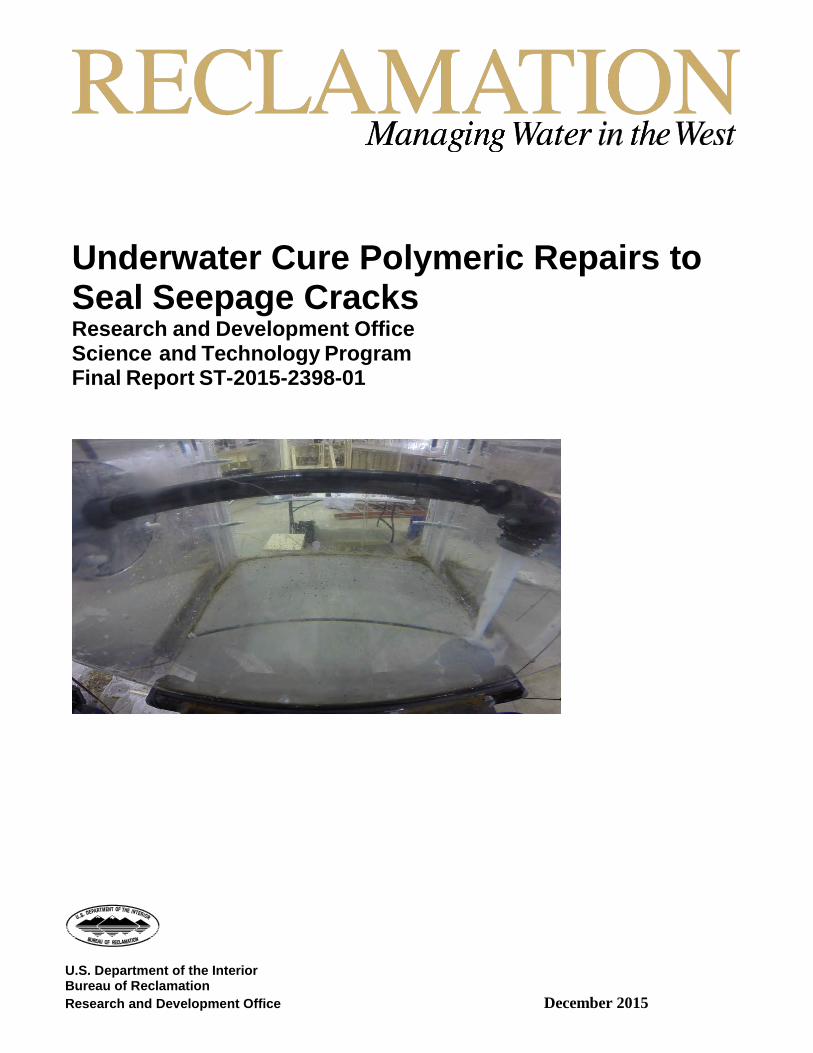
Underwater Cure Polymeric Repairs to Seal Seepage Cracks Research and Development Office Science and Technology Program Final Report ST-2015-2398-01
U.S. Department of the Interior Bureau of Reclamation Research and Development Office December 2015
Mission Statements The U.S. Department of the Interior protects America’s natural resources and heritage, honors our cultures and tribal communities, and supplies the energy to power our future.
The mission of the Bureau of Reclamation is to manage, develop, and protect water and related resources in an environmentally and economically sound manner in the interest of the American public.
REPORT DOCUMENTATION PAGE Form Approved OMB No. 0704-0188
T1. REPORT DATE 09/2015
T2. REPORT TYPE Research
T3. DATES COVERED
T4. TITLE AND SUBTITLE Underwater Cure Polymeric Repairs to Seal Seepage Cracks
7. PERFORMING ORGANIZATION NAME(S) AND ADDRESS(ES) Bureau of Reclamation Technical Service Center Concrete, Geotechnical, and Structural Laboratory (86-68530)
8. PERFORMING ORGANIZATION REPORT NUMBER
MERL-2015-081
9. SPONSORING / MONITORING AGENCY NAME(S) AND ADDRESS(ES) Research and Development Office U.S. Department of the Interior, Bureau of Reclamation, PO Box 25007, Denver CO 80225-0007
10. SPONSOR/MONITOR’S ACRONYM(S) R&D: Research and Development Office BOR/USBR: Bureau of Reclamation DOI: Department of the Interior 11. SPONSOR/MONITOR’S REPORT NUMBER(S) ST-2015-2398-01
12. DISTRIBUTION / AVAILABILITY STATEMENT Final report can be downloaded from Reclamation’s website: https://www.usbr.gov/research/
13. SUPPLEMENTARY NOTES
14. ABSTRACT: Cracks in the concrete linings of canals allow water to leak. This paper presents laboratory research on polyurethane grouts used to seal cracks in concrete specimens underwater. A total of four grouts were tested in a custom designed test tank to simulate field conditions.
Project Name Underwater Cure Polymeric Repairs to Seal Seepage Cracks WOID Z2398
Document Underwater Cure Polymeric Repairs to Seal Seepage Cracks
Document Au t h or (s) M att h ew K l e i n . P h .D. a n d S h a n n on H ar re l l, P. E .
Document date: December 2015
Peer Reviewer Kurt von Fay, BSCE, MBA
Review Certification Peer Reviewer: I have reviewed the assigned items/sections(s) noted for the above document and believe them to be in accordance with the project requirements, standards of the profession, and Reclamation policy.
Date reviewed !2-)z, ) /; -
BUREAU OF RECLAMATION Technical Service Center, Denver, Colorado Concrete, Geotechnical, & Structural Laboratory Group, 86- 68530
Technical Memorandum No. MERL-2015-081
Underwater Cure Polymeric Repairs to Seal Seepage Cracks
i1.- jv ) UJ \S Prepared/Checked by: Matthew Klein, Ph.D. Date Civil Engineer, Concrete, Geotechnical, & Structural Laboratory, 86-68530
I z_ / Z7:>/ !<7 Date
REVISIONS
Date
Description
'O i!! rn 0. i!! Cl.
'O
""' ."c' ()
ro - ·- r>n .c 0 " 0. ,_' <0(.
..... .@ "' >
C"l'. O"''.
Disclaimer Information in this report may not be used for advertising or promotional purposes. The data and findings should not be construed as an endorsement of any product or firm by the Bureau of Reclamation, Department of the Interior, or Federal Government. The products evaluated in the report were evaluated for purposes specific to the Bureau of Reclamation mission. Reclamation gives no warranties or guarantees, expressed or implied, for the products evaluated in this report, including merchantability or fitness for a particular purpose.
Acknowledgements This research could not have been completed without the hard work and dedication of our summer interns James Waller and Matthew Becker. In addition, Marty Poos, Dane Cheek, James Hastings, and Jason Black were all instrumental in helping our interns build our test tank and frame. We would like to recognize Tony Wahl who designed our test tank and provided us general hydraulic support. Finally, we would like to thank the Hydraulic Investigation and Lab Services department for allowing us the use of their lab to perform our experiments.
Executive Summary Water seepage from cracks in concrete canals has been an issue for Reclamation infrastructure for decades. Dewatering canals can be costly and lead to long service delays while repair materials are installed. Furthermore, rigid polymeric crack repair materials (for example, epoxy) may lead to cracking of the adjacent concrete.
Polyurethane grouts are a solution for this problem because they use water to cure. Using the water in the canal to cure the repair material eliminates the need to dewater. Polyurethane grouts are also an excellent repair material for sealing seepage cracks because many formulations are flexible and will allow some minor crack movement while keeping the crack sealed.
In this research study, four polyurethane grouts were injected underwater into a crack using a single component pump and an injection nozzle. A 5 psi pressure head was applied to simulate a crack at the bottom of a 12 foot deep canal. The polyurethane grouts that were used were as follows.
• ST-504 Hydrophilic Vari-Gel Injection Resin distributed by Strata-Tech,
Inc. • ST-524/ST-525 Hydrophobic Poly-Foam Injection Resin distributed by
Strata-Tech, Inc. • AV-330 SAFEGUARD Hydrophilic Polyurethane Foam distributed by
Avanti International • AV-248/249 FLEXSEAL Hydrophobic Polyurethane Foam distributed by
Avanti International
The four grouts were rated based on 1) the effectiveness of the grout to seal the crack, 2) visibility of the water during grouting, and 3) ease of injection. The research indicated that only one of the four polyurethane grouts worked better than the others in this test and would be a likely candidate for use as an underwater installation and cure repair material for sealing cracks in concrete canals (see Table 1).
2
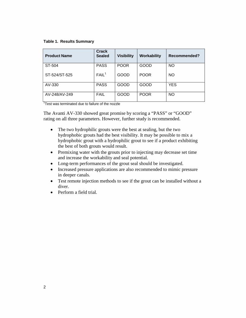
Table 1. Results Summary
1Test was terminated due to failure of the nozzle
The Avanti AV-330 showed great promise by scoring a “PASS” or “GOOD” rating on all three parameters. However, further study is recommended.
• The two hydrophilic grouts were the best at sealing, but the two
hydrophobic grouts had the best visibility. It may be possible to mix a hydrophobic grout with a hydrophilic grout to see if a product exhibiting the best of both grouts would result.
• Premixing water with the grouts prior to injecting may decrease set time and increase the workability and seal potential.
• Long-term performances of the grout seal should be investigated. • Increased pressure applications are also recommended to mimic pressure
in deeper canals. • Test remote injection methods to see if the grout can be installed without a
diver. • Perform a field trial.
Product Name
Crack Sealed
Visibility
Workability
Recommended?
ST-504 PASS POOR GOOD NO
ST-524/ST-525 FAIL1 GOOD POOR NO
AV-330 PASS GOOD GOOD YES
AV-248/AV-249 FAIL GOOD POOR NO
3
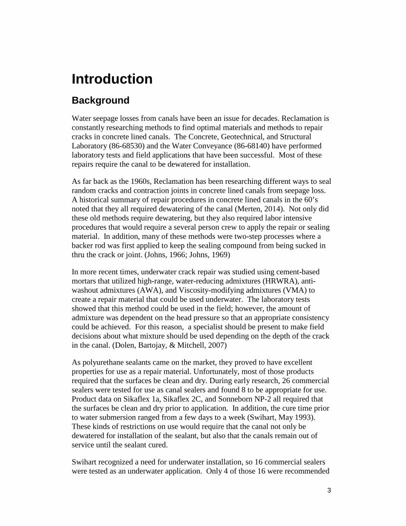
Introduction Background
Water seepage losses from canals have been an issue for decades. Reclamation is constantly researching methods to find optimal materials and methods to repair cracks in concrete lined canals. The Concrete, Geotechnical, and Structural Laboratory (86-68530) and the Water Conveyance (86-68140) have performed laboratory tests and field applications that have been successful. Most of these repairs require the canal to be dewatered for installation.
As far back as the 1960s, Reclamation has been researching different ways to seal random cracks and contraction joints in concrete lined canals from seepage loss. A historical summary of repair procedures in concrete lined canals in the 60’s noted that they all required dewatering of the canal (Merten, 2014). Not only did these old methods require dewatering, but they also required labor intensive procedures that would require a several person crew to apply the repair or sealing material. In addition, many of these methods were two-step processes where a backer rod was first applied to keep the sealing compound from being sucked in thru the crack or joint. (Johns, 1966; Johns, 1969)
In more recent times, underwater crack repair was studied using cement-based mortars that utilized high-range, water-reducing admixtures (HRWRA), anti- washout admixtures (AWA), and Viscosity-modifying admixtures (VMA) to create a repair material that could be used underwater. The laboratory tests showed that this method could be used in the field; however, the amount of admixture was dependent on the head pressure so that an appropriate consistency could be achieved. For this reason, a specialist should be present to make field decisions about what mixture should be used depending on the depth of the crack in the canal. (Dolen, Bartojay, & Mitchell, 2007)
As polyurethane sealants came on the market, they proved to have excellent properties for use as a repair material. Unfortunately, most of those products required that the surfaces be clean and dry. During early research, 26 commercial sealers were tested for use as canal sealers and found 8 to be appropriate for use. Product data on Sikaflex 1a, Sikaflex 2C, and Sonneborn NP-2 all required that the surfaces be clean and dry prior to application. In addition, the cure time prior to water submersion ranged from a few days to a week (Swihart, May 1993). These kinds of restrictions on use would require that the canal not only be dewatered for installation of the sealant, but also that the canals remain out of service until the sealant cured.
Swihart recognized a need for underwater installation, so 16 commercial sealers were tested as an underwater application. Only 4 of those 16 were recommended
4
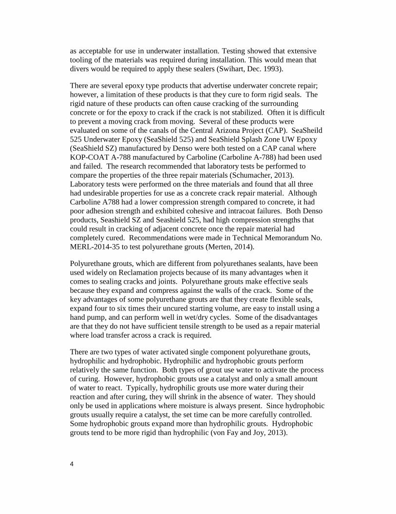
as acceptable for use in underwater installation. Testing showed that extensive tooling of the materials was required during installation. This would mean that divers would be required to apply these sealers (Swihart, Dec. 1993).
There are several epoxy type products that advertise underwater concrete repair; however, a limitation of these products is that they cure to form rigid seals. The rigid nature of these products can often cause cracking of the surrounding concrete or for the epoxy to crack if the crack is not stabilized. Often it is difficult to prevent a moving crack from moving. Several of these products were evaluated on some of the canals of the Central Arizona Project (CAP). SeaSheild 525 Underwater Epoxy (SeaShield 525) and SeaShield Splash Zone UW Epoxy (SeaShield SZ) manufactured by Denso were both tested on a CAP canal where KOP-COAT A-788 manufactured by Carboline (Carboline A-788) had been used and failed. The research recommended that laboratory tests be performed to compare the properties of the three repair materials (Schumacher, 2013). Laboratory tests were performed on the three materials and found that all three had undesirable properties for use as a concrete crack repair material. Although Carboline A788 had a lower compression strength compared to concrete, it had poor adhesion strength and exhibited cohesive and intracoat failures. Both Denso products, Seashield SZ and Seashield 525, had high compression strengths that could result in cracking of adjacent concrete once the repair material had completely cured. Recommendations were made in Technical Memorandum No. MERL-2014-35 to test polyurethane grouts (Merten, 2014).
Polyurethane grouts, which are different from polyurethanes sealants, have been used widely on Reclamation projects because of its many advantages when it comes to sealing cracks and joints. Polyurethane grouts make effective seals because they expand and compress against the walls of the crack. Some of the key advantages of some polyurethane grouts are that they create flexible seals, expand four to six times their uncured starting volume, are easy to install using a hand pump, and can perform well in wet/dry cycles. Some of the disadvantages are that they do not have sufficient tensile strength to be used as a repair material where load transfer across a crack is required.
There are two types of water activated single component polyurethane grouts, hydrophilic and hydrophobic. Hydrophilic and hydrophobic grouts perform relatively the same function. Both types of grout use water to activate the process of curing. However, hydrophobic grouts use a catalyst and only a small amount of water to react. Typically, hydrophilic grouts use more water during their reaction and after curing, they will shrink in the absence of water. They should only be used in applications where moisture is always present. Since hydrophobic grouts usually require a catalyst, the set time can be more carefully controlled. Some hydrophobic grouts expand more than hydrophilic grouts. Hydrophobic grouts tend to be more rigid than hydrophilic (von Fay and Joy, 2013).
5
Polyurethane grouts have been used successfully at several Reclamation locations including Grand Coulee Pump Generation Plant, Folsom Dam Power Plant deck, Davis Dam Power Plant and transformer decks, Imperial Dam Water Diversion Structure and Cedar Bluff Dam Outlet Works Tunnel. At Grand Coulee, Folsom and Davis, hydrophilic and a combination of hydrophilic and hydrophobic grouts were used to repair failed water-stop expansion joints above critical equipment in the structures (von Fay and Joy, 2013). At Imperial Dam, hydrophobic grout was also used to seal an expansion joint and various cracks throughout the structure. In this case, there was no water stop in the expansion joint (Klein, 2014). At Cedar Bluff, hydrophobic grout was used to seal a failed water-stop expansion joint above a 5 foot 6 inch outlet works pipe (Klein, 2015).
Goals for the Project
Past research has indicated a need for a flexible concrete canal repair materials that can be applied and cured underwater. This research project will attempt to achieve the following:
1) Determine the suitability of Strata-Tech ST 504, Strata-Tech ST-524/525,
Avanti AV-330 Safeguard, and Avanti AV-248/249 Flexseal polyurethane grouts as concrete canal repair materials by applying the grout underwater and allowing them to cure underwater in a laboratory setting.
2) Determine the potential of these four polyurethane grouts to be applied without tooling into the crack. This will be used to determine the potential for the grout to be installed without divers.
3) Determine the best polyurethane grout based on visibility in the water after the grout has been discharged, the ease of use underwater, and most importantly, its ability to seal the crack.
Conclusions The laboratory testing that was conducted indicated that only one of the polyurethane grouts would be an appropriate material for sealing concrete canal linings underwater. Tables 2 and 3 below provide a summary of the results.
Table 2. Recommended Grouts
1 Slow flow into crack
Product Name
Crack Sealed
Visibility
Workability
AV-330 PASS GOOD GOOD1
6
Table 3. Not Recommended Grouts
1 Slow flow into crack
2 Floats
3 Test was terminated due to failure of the nozzle
• Laboratory testing of the polyurethane grouts determined that the single component hydrophilic polyurethane grouts were the best suited for underwater cure and application. In the case of both of the two-part hydrophobic grout, the reacted grout floated making it difficult to inject into the crack.
• Viscosity of the polyurethane grout appeared to have a large impact on the performance of the polyurethane grout under water. AV-330 was characterized by the technical product data sheet as having mid-range viscosity of 350 to 750 cP at 72o F (Avanti, 2014). Because of the viscosity, AV-330 slowly flowed thru the cracks, thus increasing its occupy time in the crack and preventing flow through.
• All the polyurethane grouts were applied using only an injection nozzle and a pump. Additional tooling was not required. The grouts simply followed the hydraulic pressure applied to the concrete specimen to push the grout thru the crack. The laboratory tests indicate that Avanti AV-330 has potential to be applied without a diver. However, a field test is still recommended.
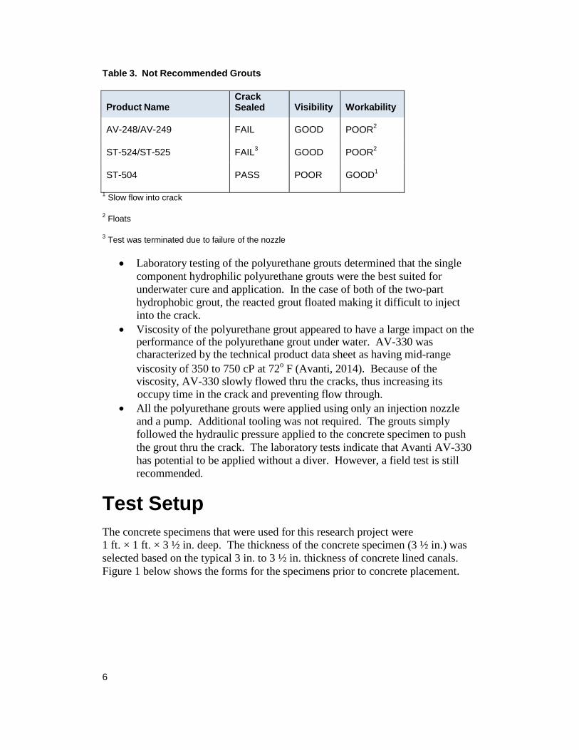
Test Setup The concrete specimens that were used for this research project were 1 ft. × 1 ft. × 3 ½ in. deep. The thickness of the concrete specimen (3 ½ in.) was selected based on the typical 3 in. to 3 ½ in. thickness of concrete lined canals. Figure 1 below shows the forms for the specimens prior to concrete placement.
Product Name
Crack Sealed
Visibility
Workability
AV-248/AV-249 FAIL GOOD POOR2
ST-524/ST-525 FAIL3 GOOD POOR2
ST-504 PASS POOR GOOD1
7
Figure 1. Concrete forms
The specimens were created using a 4500 psi pea gravel concrete mix with a 0.43 water-cement ratio supplied by Bestway Concrete. A ¼ in. deep groove was saw- cut at the center of the specimen so that when the concrete specimen was broken, the crack would form at a predetermined location. The crack was required to be located at the center of the specimen based on the location of the injection rod in the test tank. It was also desirable that the crack be straight since the injection rod had no lateral maneuverability.
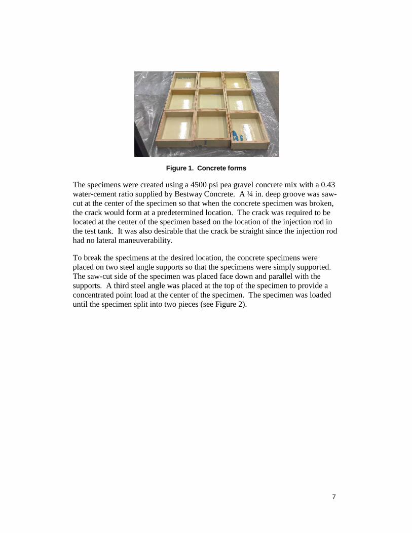
To break the specimens at the desired location, the concrete specimens were placed on two steel angle supports so that the specimens were simply supported. The saw-cut side of the specimen was placed face down and parallel with the supports. A third steel angle was placed at the top of the specimen to provide a concentrated point load at the center of the specimen. The specimen was loaded until the specimen split into two pieces (see Figure 2).
8
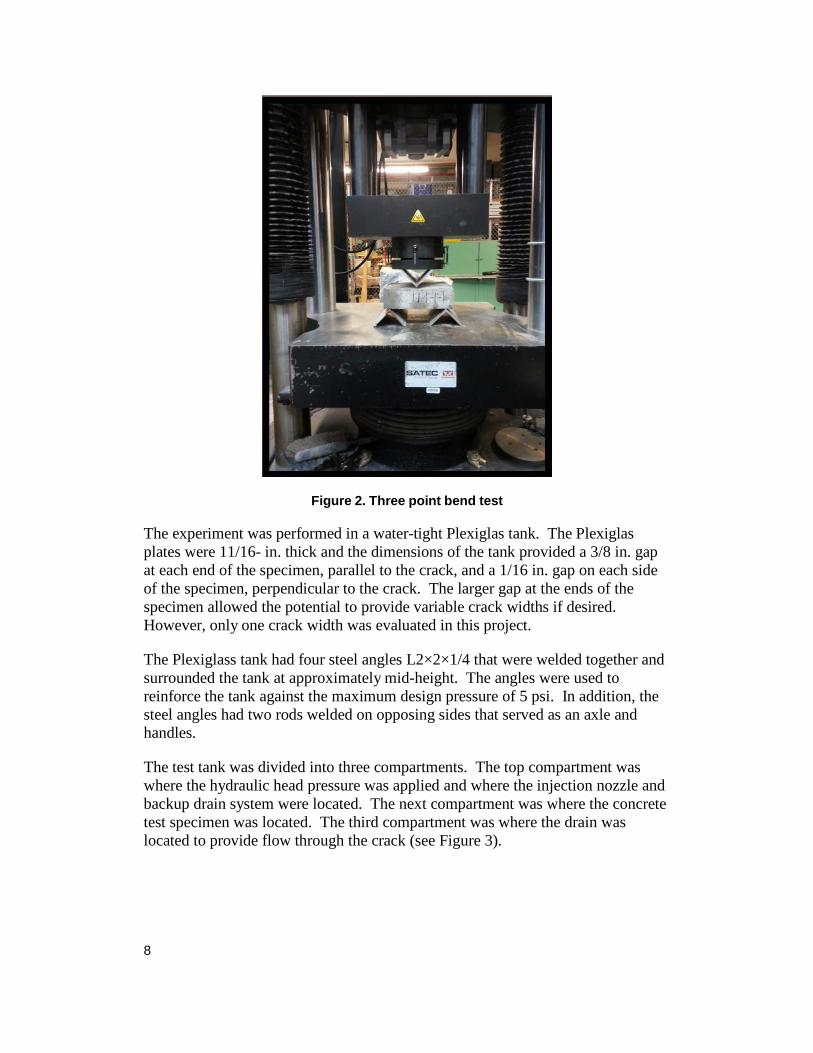
Figure 2. Three point bend test
The experiment was performed in a water-tight Plexiglas tank. The Plexiglas plates were 11/16- in. thick and the dimensions of the tank provided a 3/8 in. gap at each end of the specimen, parallel to the crack, and a 1/16 in. gap on each side of the specimen, perpendicular to the crack. The larger gap at the ends of the specimen allowed the potential to provide variable crack widths if desired. However, only one crack width was evaluated in this project.
The Plexiglass tank had four steel angles L2×2×1/4 that were welded together and surrounded the tank at approximately mid-height. The angles were used to reinforce the tank against the maximum design pressure of 5 psi. In addition, the steel angles had two rods welded on opposing sides that served as an axle and handles.
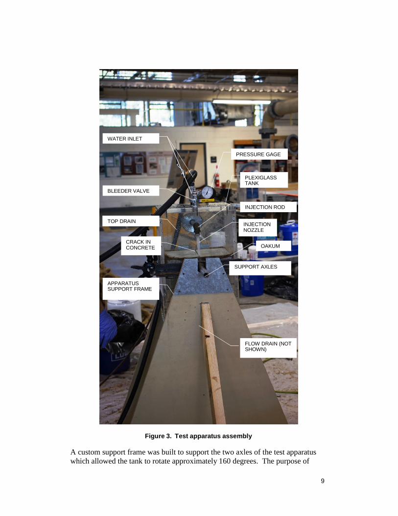
The test tank was divided into three compartments. The top compartment was where the hydraulic head pressure was applied and where the injection nozzle and backup drain system were located. The next compartment was where the concrete test specimen was located. The third compartment was where the drain was located to provide flow through the crack (see Figure 3).
9
Figure 3. Test apparatus assembly
A custom support frame was built to support the two axles of the test apparatus which allowed the tank to rotate approximately 160 degrees. The purpose of
WATER INLET
PRESSURE GAGE
PLEXIGLASS TANK
BLEEDER VALVE
INJECTION ROD
TOP DRAIN INJECTION NOZZLE
CRACK IN CONCRETE OAKUM
SUPPORT AXLES
APPARATUS SUPPORT FRAME
FLOW DRAIN (NOT SHOWN)
10
allowing the tank to rotate was so the top of the tank could be drained if and when the crack in the concrete was sealed. The tank could not be fully rotated 180 degrees due to the injection rod location. The design of the frame allowed access on 2 sides of the test tank. The frame was mounted on wheels so that the test could be easily moved.
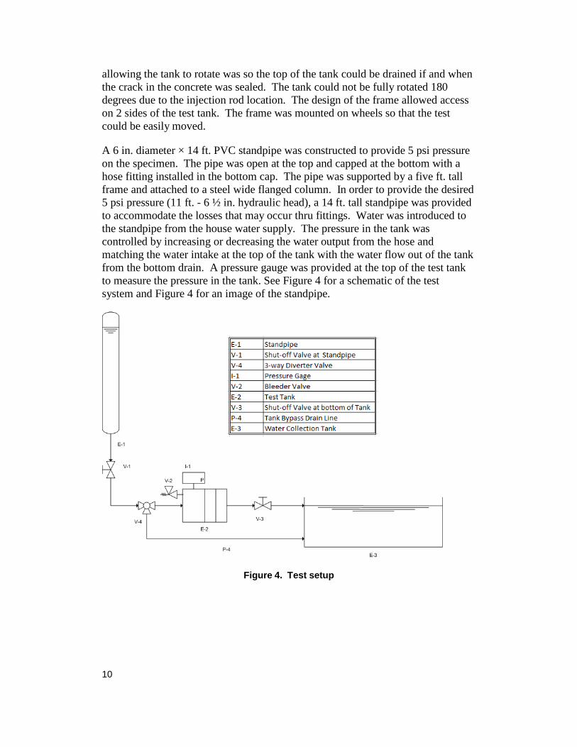
A 6 in. diameter × 14 ft. PVC standpipe was constructed to provide 5 psi pressure on the specimen. The pipe was open at the top and capped at the bottom with a hose fitting installed in the bottom cap. The pipe was supported by a five ft. tall frame and attached to a steel wide flanged column. In order to provide the desired 5 psi pressure (11 ft. - 6 ½ in. hydraulic head), a 14 ft. tall standpipe was provided to accommodate the losses that may occur thru fittings. Water was introduced to the standpipe from the house water supply. The pressure in the tank was controlled by increasing or decreasing the water output from the hose and matching the water intake at the top of the tank with the water flow out of the tank from the bottom drain. A pressure gauge was provided at the top of the test tank to measure the pressure in the tank. See Figure 4 for a schematic of the test system and Figure 4 for an image of the standpipe.
Figure 4. Test setup
11
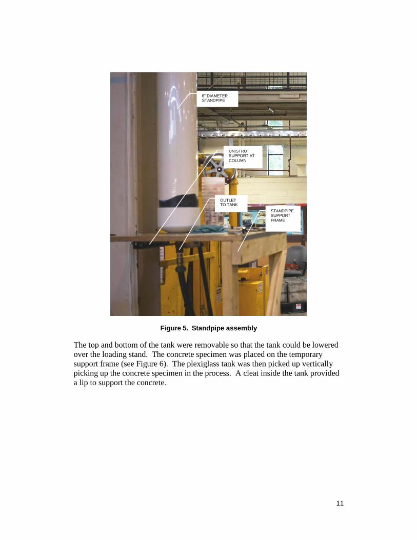
Figure 5. Standpipe assembly
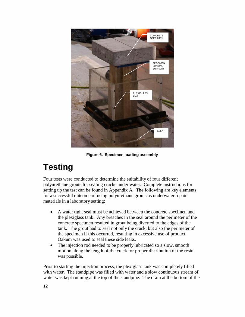
The top and bottom of the tank were removable so that the tank could be lowered over the loading stand. The concrete specimen was placed on the temporary support frame (see Figure 6). The plexiglass tank was then picked up vertically picking up the concrete specimen in the process. A cleat inside the tank provided a lip to support the concrete.
6” DIAMETER STANDPIPE
UNISTRUT SUPPORT AT COLUMN
OUTLET TO TANK
STANDPIPE SUPPORT FRAME
12
Testing
Figure 6. Specimen loading assembly
Four tests were conducted to determine the suitability of four different polyurethane grouts for sealing cracks under water. Complete instructions for setting up the test can be found in Appendix A. The following are key elements for a successful outcome of using polyurethane grouts as underwater repair materials in a laboratory setting:
• A water tight seal must be achieved between the concrete specimen and
the plexiglass tank. Any breaches in the seal around the perimeter of the concrete specimen resulted in grout being diverted to the edges of the tank. The grout had to seal not only the crack, but also the perimeter of the specimen if this occurred, resulting in excessive use of product. Oakum was used to seal these side leaks.
• The injection rod needed to be properly lubricated so a slow, smooth motion along the length of the crack for proper distribution of the resin was possible.
Prior to starting the injection process, the plexiglass tank was completely filled with water. The standpipe was filled with water and a slow continuous stream of water was kept running at the top of the standpipe. The drain at the bottom of the
CONCRETE SPECIMEN
SPECIMEN LOADING SUPPORT
PLEXIGLASS BOX
CLEAT
13
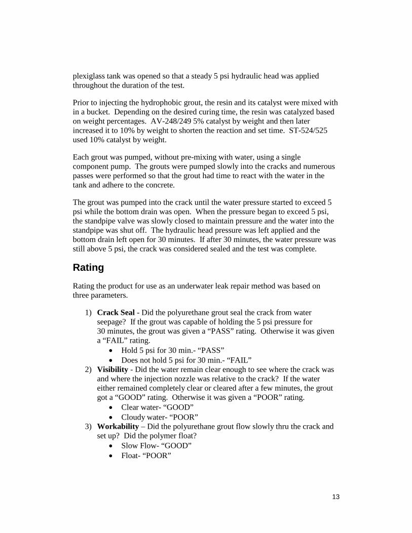
plexiglass tank was opened so that a steady 5 psi hydraulic head was applied throughout the duration of the test.
Prior to injecting the hydrophobic grout, the resin and its catalyst were mixed with in a bucket. Depending on the desired curing time, the resin was catalyzed based on weight percentages. AV-248/249 5% catalyst by weight and then later increased it to 10% by weight to shorten the reaction and set time. ST-524/525 used 10% catalyst by weight.
Each grout was pumped, without pre-mixing with water, using a single component pump. The grouts were pumped slowly into the cracks and numerous passes were performed so that the grout had time to react with the water in the tank and adhere to the concrete.
The grout was pumped into the crack until the water pressure started to exceed 5 psi while the bottom drain was open. When the pressure began to exceed 5 psi, the standpipe valve was slowly closed to maintain pressure and the water into the standpipe was shut off. The hydraulic head pressure was left applied and the bottom drain left open for 30 minutes. If after 30 minutes, the water pressure was still above 5 psi, the crack was considered sealed and the test was complete.
Rating
Rating the product for use as an underwater leak repair method was based on three parameters.
1) Crack Seal - Did the polyurethane grout seal the crack from water
seepage? If the grout was capable of holding the 5 psi pressure for 30 minutes, the grout was given a “PASS” rating. Otherwise it was given a “FAIL” rating.
• Hold 5 psi for 30 min.- “PASS” • Does not hold 5 psi for 30 min.- “FAIL”
2) Visibility - Did the water remain clear enough to see where the crack was and where the injection nozzle was relative to the crack? If the water either remained completely clear or cleared after a few minutes, the grout got a “GOOD” rating. Otherwise it was given a “POOR” rating.
• Clear water- “GOOD” • Cloudy water- “POOR”
3) Workability – Did the polyurethane grout flow slowly thru the crack and set up? Did the polymer float?
• Slow Flow- “GOOD” • Float- “POOR”
14
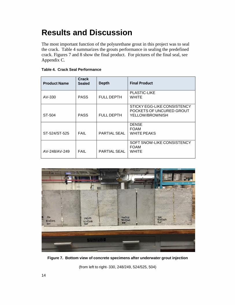
Results and Discussion The most important function of the polyurethane grout in this project was to seal the crack. Table 4 summarizes the grouts performance in sealing the predefined crack. Figures 7 and 8 show the final product. For pictures of the final seal, see Appendix C.
Table 4. Crack Seal Performance
Product Name
Crack Sealed Depth Final Product
AV-330
PASS
FULL DEPTH
PLASTIC-LIKE WHITE
ST-504
PASS
FULL DEPTH
STICKY EGG-LIKE CONSISTENCY POCKETS OF UNCURED GROUT YELLOW/BROWNISH
ST-524/ST-525
FAIL
PARTIAL SEAL
DENSE FOAM WHITE PEAKS
AV-248/AV-249
FAIL
PARTIAL SEAL
SOFT SNOW-LIKE CONSISTENCY FOAM WHITE
Figure 7. Bottom view of concrete specimens after underwater grout injection
(from left to right- 330, 248/249, 524/525, 504)
15
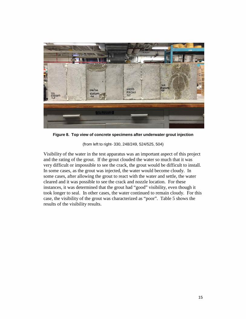
Figure 8. Top view of concrete specimens after underwater grout injection
(from left to right- 330, 248/249, 524/525, 504)
Visibility of the water in the test apparatus was an important aspect of this project and the rating of the grout. If the grout clouded the water so much that it was very difficult or impossible to see the crack, the grout would be difficult to install. In some cases, as the grout was injected, the water would become cloudy. In some cases, after allowing the grout to react with the water and settle, the water cleared and it was possible to see the crack and nozzle location. For these instances, it was determined that the grout had “good” visibility, even though it took longer to seal. In other cases, the water continued to remain cloudy. For this case, the visibility of the grout was characterized as “poor”. Table 5 shows the results of the visibility results.
16
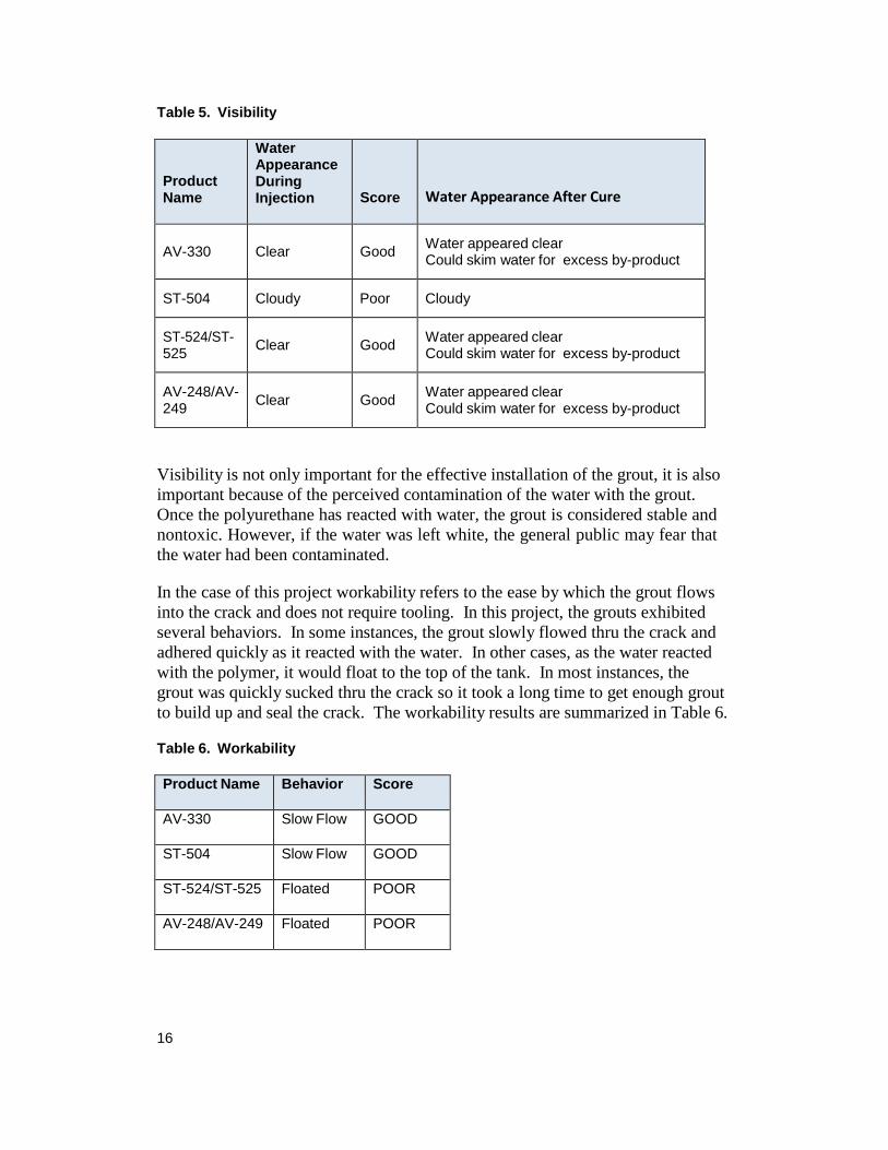
Table 5. Visibility
Product Name
Water Appearance During Injection
Score
Water Appearance After Cure
AV-330
Clear
Good Water appeared clear
Could skim water for excess by-product
ST-504 Cloudy Poor Cloudy
ST-524/ST- 525
Clear
Good Water appeared clear
Could skim water for excess by-product
AV-248/AV- 249
Clear
Good Water appeared clear
Could skim water for excess by-product
Visibility is not only important for the effective installation of the grout, it is also important because of the perceived contamination of the water with the grout. Once the polyurethane has reacted with water, the grout is considered stable and nontoxic. However, if the water was left white, the general public may fear that the water had been contaminated.
In the case of this project workability refers to the ease by which the grout flows into the crack and does not require tooling. In this project, the grouts exhibited several behaviors. In some instances, the grout slowly flowed thru the crack and adhered quickly as it reacted with the water. In other cases, as the water reacted with the polymer, it would float to the top of the tank. In most instances, the grout was quickly sucked thru the crack so it took a long time to get enough grout to build up and seal the crack. The workability results are summarized in Table 6.
Table 6. Workability
Product Name Behavior Score
AV-330 Slow Flow GOOD
ST-504 Slow Flow GOOD
ST-524/ST-525 Floated POOR
AV-248/AV-249 Floated POOR
17
Future Recommendations
The results of this study showed great promise that the polyurethane grouts could be injected into cracks in concrete canals to seal seepage leaks without having to dewater the canal or use divers. However, further study is recommended as noted below.
• A field trial should be performed to see if soil behind the crack will have
an impact on the performance of the seal. • Some canals are deeper than the 11 ft. – 6 ½ in. hydraulic pressure that
was tested. The effects of higher pressures should be investigated. • The hydrophilic grouts sealed the cracks, but the hydrophobic grouts kept
the water clearer. An investigation should be performed to see if mixing two or more different types (hydrophobic and hydrophilic) of grouts and then injecting the final product into the crack would have a more desired effect of clearer water with a good seal.
• Some of the grouts took too long to react with the water in the tank. Investigate if using a two part pump that would mix water with the grout prior to injecting into the crack would result in faster setup time and less waste.
• Study long term durability of the crack seal. The research in this project only studied if the crack was sealed, but did not study how long the seal would hold.
Dolen, T., Bartojay, K., & Mitchell, K., Underwater Crack Repair, Bureau of Reclamation, Technical Service Center, Materials Engineering and Research Laboratory, Report DSO-07-10, September 2007
von Fay, Kurt F., Joy, Westin T., Repairing Leaking Expansion Joints at Reclamation Facilities, Concrete Repair Bulletin, Vol. 26, No.2, Pages 18 to 21, March/April 2013
Johns, H., Sealing Systems for Contraction Joints in Concrete Canal Lining- San Luis Canal – Central Valley Project, Bureau of Reclamation, Division of Research, Chemical Engineering Branch, Report No. ChE-60, June 23, 1966
Johns, H., Field Tests of Crack and Joint Sealing Compounds in Concrete Canal Linings-Interim Report, Bureau of Reclamation, Division of Research, Chemical Engineering Branch, Report No. ChE-67, June 1969
Klein, Matthew, Laguna Water Control Structure (WCS) 3 and Imperial Dam Water Diversion Structure (WDS) Epoxy Injection; Gila Canal Diversion Structure Water Delivery System Headworks (WDSH) Chemical Grouting Travel Report, Bureau of Reclamation, Technical Service Center, Denver, Colorado, April 8, 2014
Klein, Matthew, Cedar Bluff Dam Outlet Works Tunnel Grouting Travel Report, Bureau of Reclamation, Technical Service Center, Denver Colorado, June 1, 2015
Kosmatka, S. H., Kerkhoff, B., & Panarese, W. C. (2002), Fundamentals of Concrete. Design and Control of Concrete Mixtures (14th ed., p.3). Skokie, Illinois: Portland Cement Association
Merten, B., Underwater Cure Epoxy Repair for Active Cracks in Concrete Canal
Linings, Bureau of Reclamation, Technical Service Center, Materials
Engineering and Research Laboratory, Technical Memorandum No. MERL-2014-35, April 2014
Schumacher, D., Trial Use of SeaShield 525 Underwater Epoxy and SeaShield Splash Zone UW Epoxy, Central Arizona Project memo, dated July 29, 2013
Strata-Tech, Inc. (retrieved 2015). ST-504 Vari-Gel Injection Resin [data sheet]. Retrieved from http://www.strata-tech.com/tds/504.pdf
Strata-Tech, Inc. (retrieved 2015). ST-5244 Poly-Foam Injection Resin [data
sheet]. Retrieved from http://www.strata-tech.com/tds/524.pdf
Swihart, J., Elastomeric Canal Sealants: Air-Water-Heat Study, Bureau of Reclamation, Research and Laboratory Services Division, Materials and Engineering Branch, R-93-09, May 1993
Swihart, J., Elastomeric Canal Sealants: Application to Wet Concrete Dry-Damp- Underwater Study, Bureau of Reclamation, Research and Laboratory Services Division, Materials Engineering Branch, R-93-18, December 1993
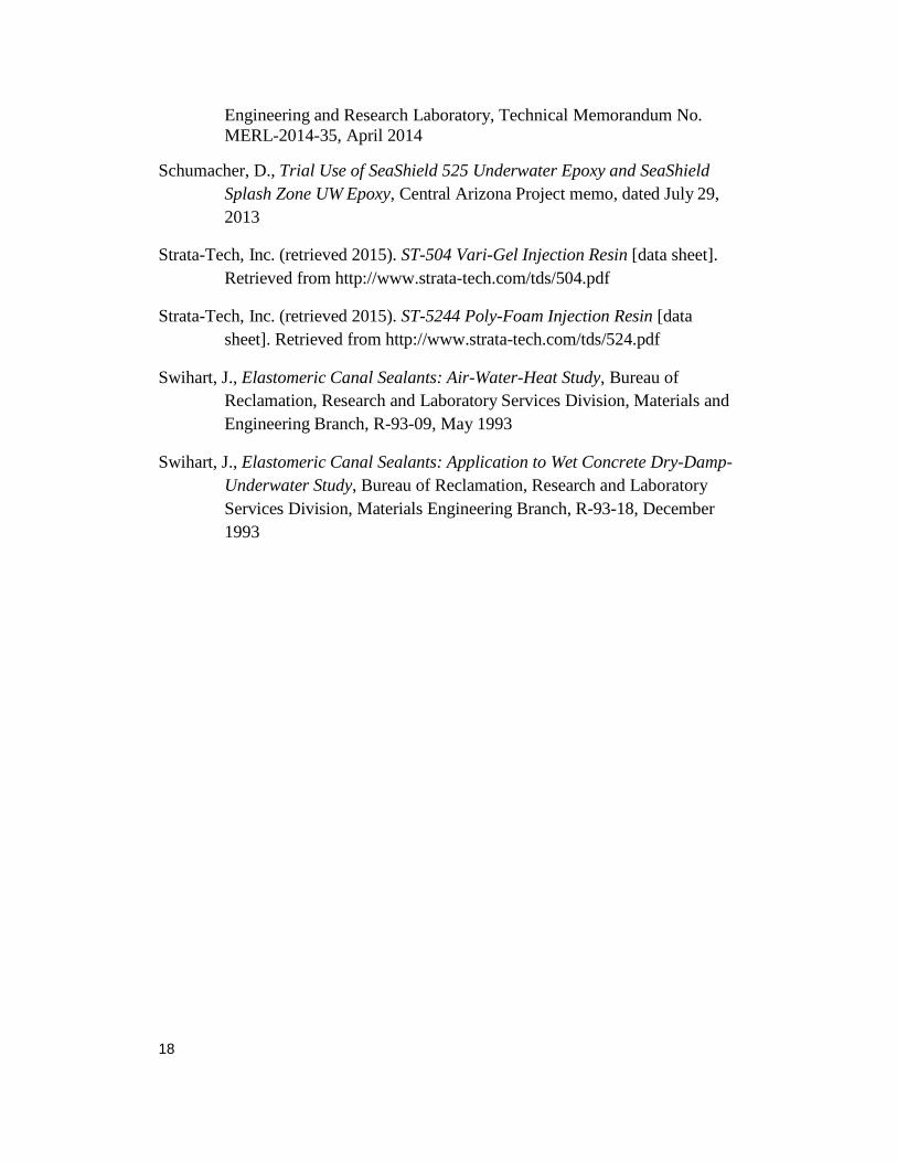
1) Apply M-D Building Products EPDM- All Climate Rubber Weatherseal for gaps 1/8 in. to 7/32 in. to the top of the specimen support box.
2) Set the precut concrete specimen on the specimen support box.
Figure A-1. Specimen stacking on specimen support box
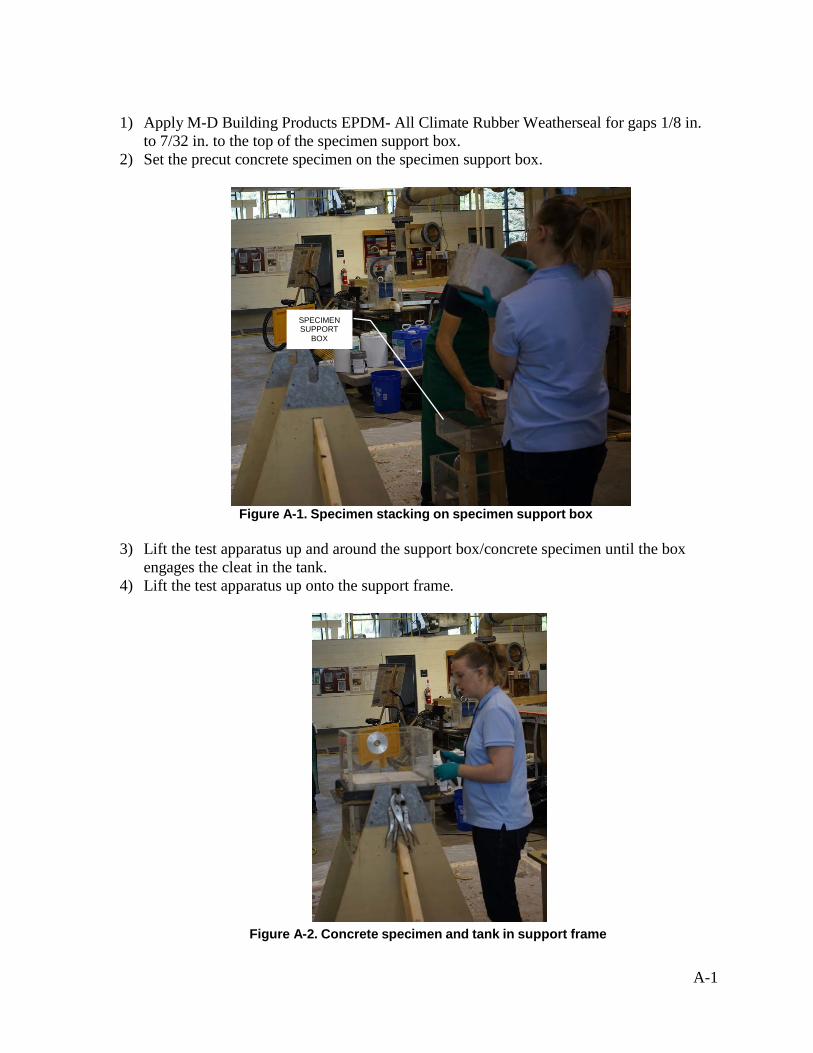
3) Lift the test apparatus up and around the support box/concrete specimen until the box
engages the cleat in the tank. 4) Lift the test apparatus up onto the support frame.
Figure A-2. Concrete specimen and tank in support frame
SPECIMEN SUPPORT
BOX
A-2
5) Clean the bottom of the apparatus tank with a damp rag to remove any particles that were picked up from the floor.
6) Apply a thin coat of Dow Corning General Purpose Silicon Vacuum and Pressure System Grease to the perimeter of the tank prior to bolting the bottom lid to the bottom of the tank. Fully tighten all bolts.
7) Cut off approximately a five in. long × 3/8 in. strip of M-D Building Products white vinyl garage weather stripping. This serves as a wedge to keep the crack open while sealing the perimeter of the specimen and seals the vertical face of the crack during testing.
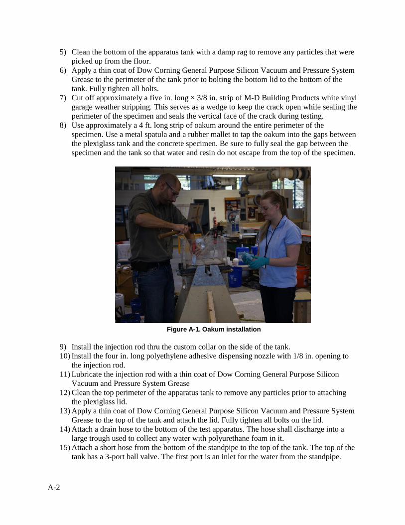
8) Use approximately a 4 ft. long strip of oakum around the entire perimeter of the specimen. Use a metal spatula and a rubber mallet to tap the oakum into the gaps between the plexiglass tank and the concrete specimen. Be sure to fully seal the gap between the specimen and the tank so that water and resin do not escape from the top of the specimen.
Figure A-1. Oakum installation
9) Install the injection rod thru the custom collar on the side of the tank. 10) Install the four in. long polyethylene adhesive dispensing nozzle with 1/8 in. opening to
the injection rod. 11) Lubricate the injection rod with a thin coat of Dow Corning General Purpose Silicon
Vacuum and Pressure System Grease 12) Clean the top perimeter of the apparatus tank to remove any particles prior to attaching
the plexiglass lid. 13) Apply a thin coat of Dow Corning General Purpose Silicon Vacuum and Pressure System
Grease to the top of the tank and attach the lid. Fully tighten all bolts on the lid. 14) Attach a drain hose to the bottom of the test apparatus. The hose shall discharge into a
large trough used to collect any water with polyurethane foam in it. 15) Attach a short hose from the bottom of the standpipe to the top of the tank. The top of the
tank has a 3-port ball valve. The first port is an inlet for the water from the standpipe.
A-3
16) Connect a second drain hose to the top of the tank at the other end of the 3-port ball valve. The opposite end of the hose shall be discharged into the large trough, similar to the bottom drain. The third port is directed into the tank.
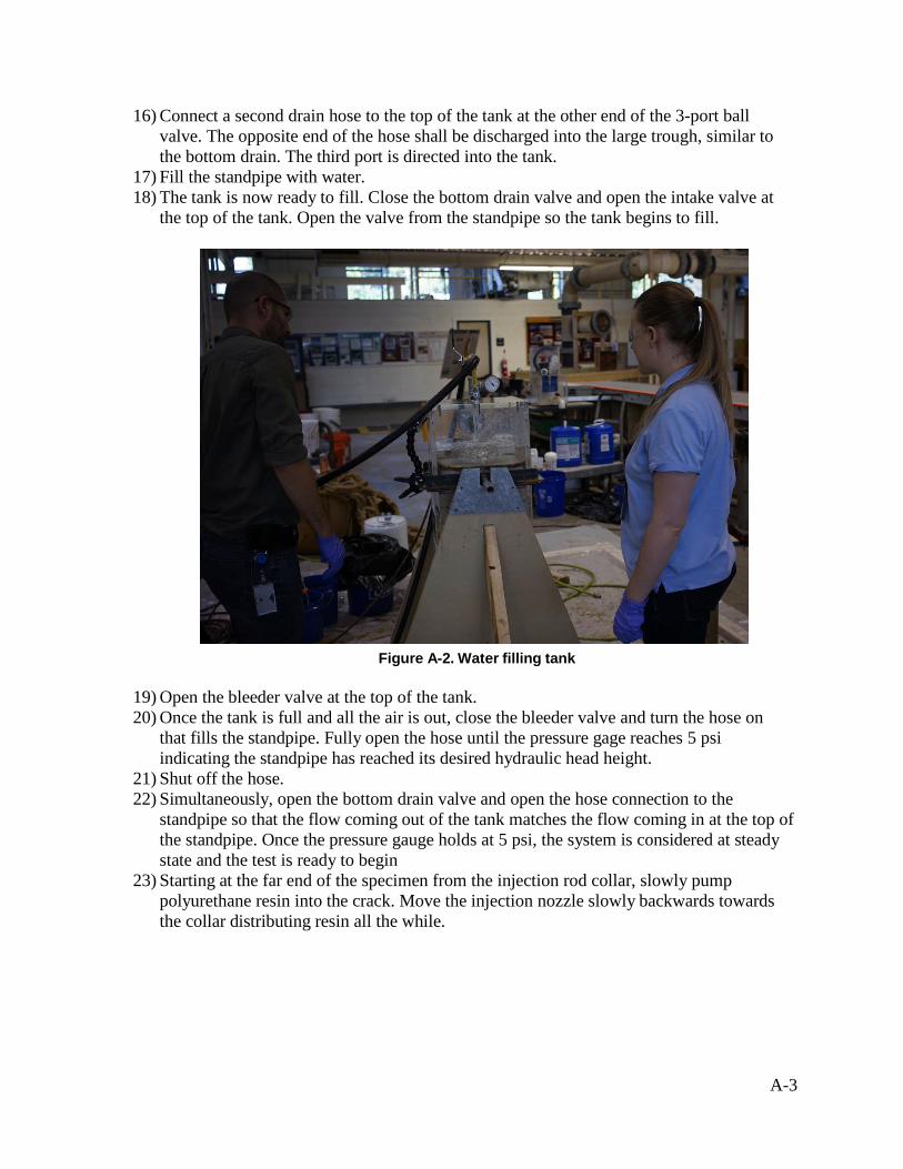
17) Fill the standpipe with water. 18) The tank is now ready to fill. Close the bottom drain valve and open the intake valve at
the top of the tank. Open the valve from the standpipe so the tank begins to fill.
Figure A-2. Water filling tank
19) Open the bleeder valve at the top of the tank. 20) Once the tank is full and all the air is out, close the bleeder valve and turn the hose on
that fills the standpipe. Fully open the hose until the pressure gage reaches 5 psi indicating the standpipe has reached its desired hydraulic head height.
21) Shut off the hose. 22) Simultaneously, open the bottom drain valve and open the hose connection to the
standpipe so that the flow coming out of the tank matches the flow coming in at the top of the standpipe. Once the pressure gauge holds at 5 psi, the system is considered at steady state and the test is ready to begin
23) Starting at the far end of the specimen from the injection rod collar, slowly pump polyurethane resin into the crack. Move the injection nozzle slowly backwards towards the collar distributing resin all the while.
A-4
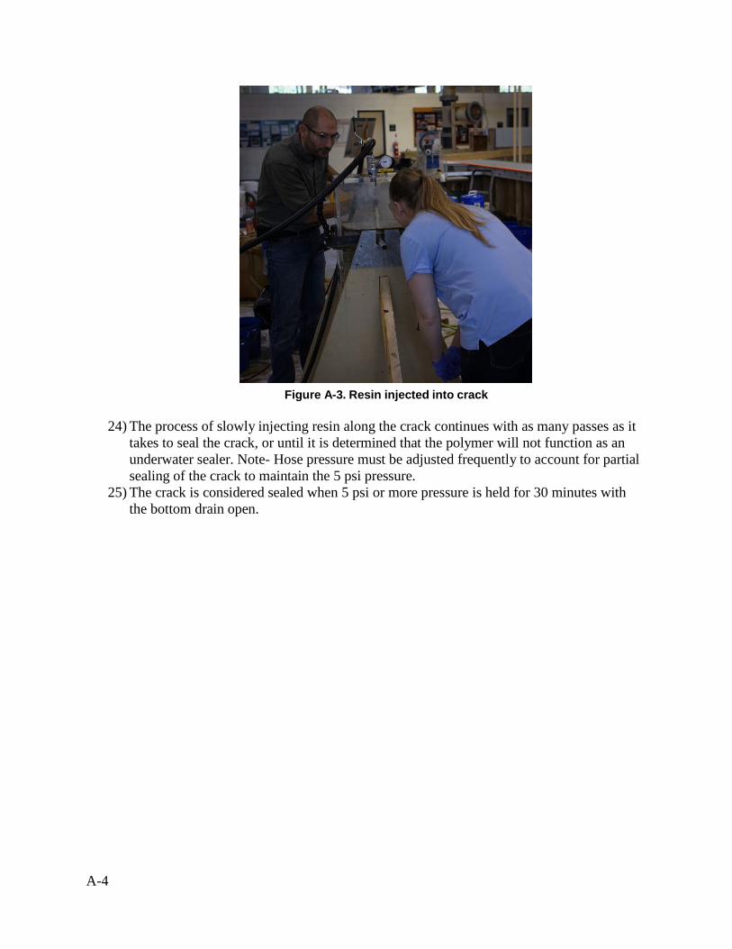
Figure A-3. Resin injected into crack
24) The process of slowly injecting resin along the crack continues with as many passes as it
takes to seal the crack, or until it is determined that the polymer will not function as an underwater sealer. Note- Hose pressure must be adjusted frequently to account for partial sealing of the crack to maintain the 5 psi pressure.
25) The crack is considered sealed when 5 psi or more pressure is held for 30 minutes with the bottom drain open.
A-5
Appendix B: Technical Data Sheets
H Y D R O P H I L I C PO LY U R E T H A N E F O A M
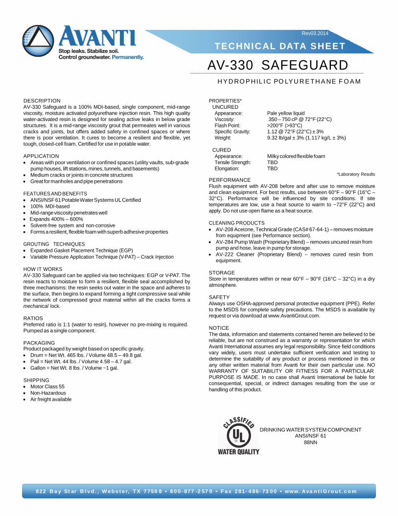
DESCRIPTION AV-330 Safeguard is a 100% MDI-based, single component, mid-range viscosity, moisture activated polyurethane injection resin. This high quality water-activated resin is designed for sealing active leaks in below grade structures. It is a mid-range viscosity grout that permeates well in various cracks and joints, but offers added safety in confined spaces or where there is poor ventilation. It cures to become a resilient and flexible, yet tough, closed-cell foam. Certified for use in potable water.
APPLICATION • Areas with poor ventilation or confined spaces (utility vaults, sub-grade
pump houses, lift stations, mines, tunnels, and basements) • Medium cracks or joints in concrete structures • Great for manholes and pipe penetrations
FEATURES AND BENEFITS • ANSI/NSF 61 Potable Water Systems UL Certified • 100% MDI-based • Mid-range viscosity penetrates well • Expands 400% – 600% • Solvent-free system and non-corrosive • Forms a resilient, flexible foam with superb adhesive properties
HOW IT WORKS AV-330 Safeguard can be applied via two techniques: EGP or V-PAT. The resin reacts to moisture to form a resilient, flexible seal accomplished by three mechanisms: the resin seeks out water in the space and adheres to the surface, then begins to expand forming a tight compressive seal while the network of compressed grout material within all the cracks forms a mechanical lock.
RATIOS Preferred ratio is 1:1 (water to resin), however no pre-mixing is required. Pumped as a single component.
PACKAGING Product packaged by weight based on specific gravity. • Drum = Net Wt. 465 lbs. / Volume 48.5 – 49.8 gal. • Pail = Net Wt. 44 lbs. / Volume 4.58 – 4.7 gal. • Gallon = Net Wt. 8 lbs. / Volume ~1 gal.
SHIPPING • Motor Class 55 • Non-Hazardous • Air freight available
*Laboratory Results PERFORMANCE Flush equipment with AV-208 before and after use to remove moisture and clean equipment. For best results, use between 60°F – 90°F (16°C – 32°C). Performance will be influenced by site conditions. If site temperatures are low, use a heat source to warm to ~72°F (22°C) and apply. Do not use open flame as a heat source.
from equipment (see Performance section). • AV-284 Pump Wash (Proprietary Blend) – removes uncured resin from
pump and hose, leave in pump for storage. • AV-222 Cleaner (Proprietary Blend) – removes cured resin from
equipment.
STORAGE Store in temperatures within or near 60°F – 90°F (16°C – 32°C) in a dry atmosphere.
SAFETY Always use OSHA-approved personal protective equipment (PPE). Refer to the MSDS for complete safety precautions. The MSDS is available by request or via download at www.AvantiGrout.com.
NOTICE The data, information and statements contained herein are believed to be reliable, but are not construed as a warranty or representation for which Avanti International assumes any legal responsibility. Since field conditions vary widely, users must undertake sufficient verification and testing to determine the suitability of any product or process mentioned in this or any other written material from Avanti for their own particular use. NO WARRANTY OF SUITABILITY OR FITNESS FOR A PARTICULAR PURPOSE IS MADE. In no case shall Avanti International be liable for consequential, special, or indirect damages resulting from the use or handling of this product.
822 B a y St ar B l v d . , W e b s t e r, T X 7 759 8 • 8 0 0 - 877 -2 57 0 • F a x 2 81- 4 86- 73 0 0 • www. A va n t i G r o u t . c o m
H Y D R O P H O B I C P O L Y U R E T HA NE F O A M
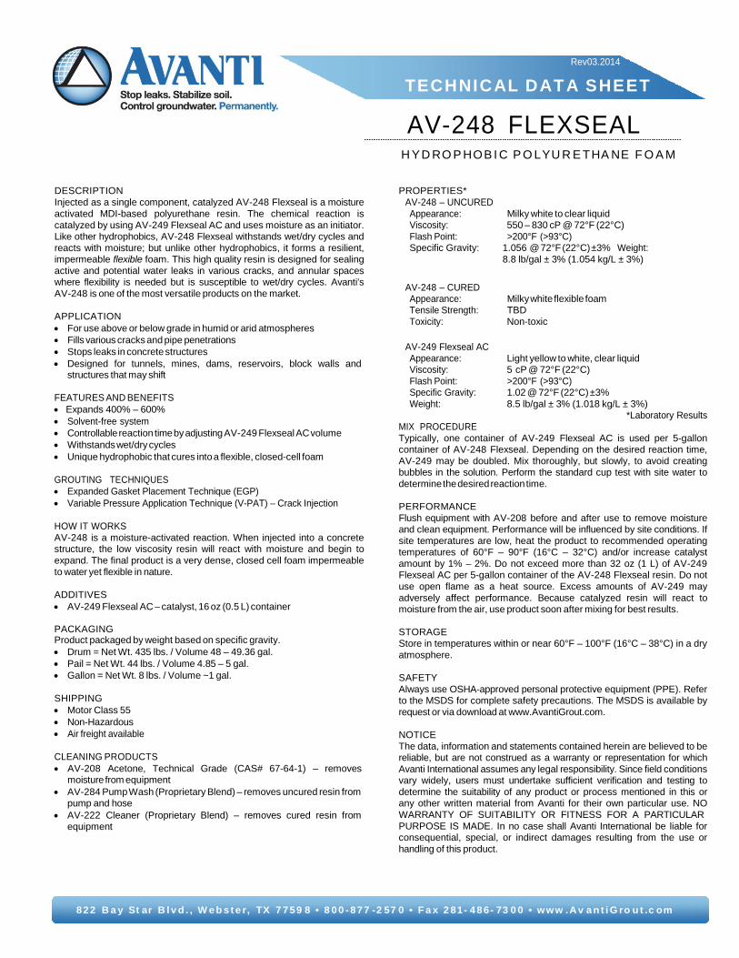
DESCRIPTION Injected as a single component, catalyzed AV-248 Flexseal is a moisture activated MDI-based polyurethane resin. The chemical reaction is catalyzed by using AV-249 Flexseal AC and uses moisture as an initiator. Like other hydrophobics, AV-248 Flexseal withstands wet/dry cycles and reacts with moisture; but unlike other hydrophobics, it forms a resilient, impermeable flexible foam. This high quality resin is designed for sealing active and potential water leaks in various cracks, and annular spaces where flexibility is needed but is susceptible to wet/dry cycles. Avanti’s AV-248 is one of the most versatile products on the market.
APPLICATION • For use above or below grade in humid or arid atmospheres • Fills various cracks and pipe penetrations • Stops leaks in concrete structures • Designed for tunnels, mines, dams, reservoirs, block walls and
structures that may shift
FEATURES AND BENEFITS • Expands 400% – 600% • Solvent-free system • Controllable reaction time by adjusting AV-249 Flexseal AC volume • Withstands wet/dry cycles • Unique hydrophobic that cures into a flexible, closed-cell foam
HOW IT WORKS AV-248 is a moisture-activated reaction. When injected into a concrete structure, the low viscosity resin will react with moisture and begin to expand. The final product is a very dense, closed cell foam impermeable to water yet flexible in nature.
ADDITIVES • AV-249 Flexseal AC – catalyst, 16 oz (0.5 L) container
PACKAGING Product packaged by weight based on specific gravity. • Drum = Net Wt. 435 lbs. / Volume 48 – 49.36 gal. • Pail = Net Wt. 44 lbs. / Volume 4.85 – 5 gal. • Gallon = Net Wt. 8 lbs. / Volume ~1 gal.
SHIPPING • Motor Class 55 • Non-Hazardous • Air freight available
*Laboratory Results MIX PROCEDURE Typically, one container of AV-249 Flexseal AC is used per 5-gallon container of AV-248 Flexseal. Depending on the desired reaction time, AV-249 may be doubled. Mix thoroughly, but slowly, to avoid creating bubbles in the solution. Perform the standard cup test with site water to determine the desired reaction time.
PERFORMANCE Flush equipment with AV-208 before and after use to remove moisture and clean equipment. Performance will be influenced by site conditions. If site temperatures are low, heat the product to recommended operating temperatures of 60°F – 90°F (16°C – 32°C) and/or increase catalyst amount by 1% – 2%. Do not exceed more than 32 oz (1 L) of AV-249 Flexseal AC per 5-gallon container of the AV-248 Flexseal resin. Do not use open flame as a heat source. Excess amounts of AV-249 may adversely affect performance. Because catalyzed resin will react to moisture from the air, use product soon after mixing for best results.
STORAGE Store in temperatures within or near 60°F – 100°F (16°C – 38°C) in a dry atmosphere.
SAFETY Always use OSHA-approved personal protective equipment (PPE). Refer to the MSDS for complete safety precautions. The MSDS is available by request or via download at www.AvantiGrout.com.
NOTICE The data, information and statements contained herein are believed to be reliable, but are not construed as a warranty or representation for which Avanti International assumes any legal responsibility. Since field conditions vary widely, users must undertake sufficient verification and testing to determine the suitability of any product or process mentioned in this or any other written material from Avanti for their own particular use. NO WARRANTY OF SUITABILITY OR FITNESS FOR A PARTICULAR PURPOSE IS MADE. In no case shall Avanti International be liable for consequential, special, or indirect damages resulting from the use or handling of this product.
822 B a y St ar B l v d . , W e b s t e r, TX 7 759 8 • 8 0 0 - 877 -2 57 0 • F a x 2 81- 4 86- 73 0 0 • www .Av a n t i G ro u t .c om
3601 104th Street Des Moines, Iowa 50322 PHONE 515/251.7770 FAX 515/251.7705 WEB SITE www.strata-tech .com EMAIL lnfo@strata-tech .com
CHEMICAL SEALANTS • WATER CONTROL MATERIALS • GROUTING EQUIPMENT
STRATA-TECH, INC.
ST-504 VARI-GEL INJECTION RESIN
INTRODUCTION
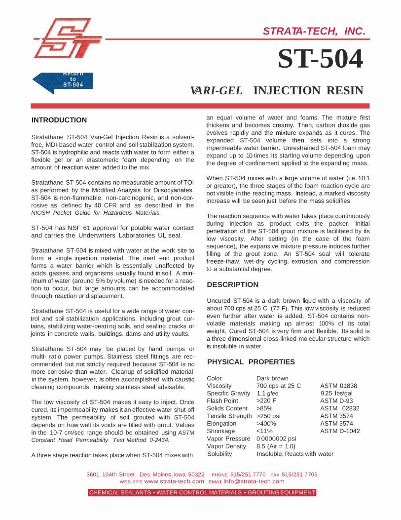
Stratathane ST-504 Vari-Gel Injection Resin is a solvent- free, MDI-based water control and soil stabilization system. ST-504 is hydrophilic and reacts with water to form either a flexible gel or an elastomeric foam depending on the amount of reaction water added to the mix.
Stratathane ST-504 contains no measurable amount of TOI as performed by the Modified Analysis for Diisocyanates. ST-504 is non-flammable, non-carcinogenic, and non-cor- rosive as defined by 40 CFR and as described in the NIOSH Pocket Guide for Hazardous Materials.
ST-504 has NSF 61 approval for potable water contact and carries the Underwriters Laboratories UL seal.
Stratathane ST-504 is mixed with water at the work site to form a single injection material. The inert end product forms a water barrier which is essentially unaffected by acids, gasses, and organisms usually found in soil. A min- imum of water (around 5% by volume) is needed for a reac- tion to occur, but large amounts can be accommodated through reaction or displacement.
Stratathane ST-504 is useful for a wide range of water con- trol and soil stabilization applications, including grout cur- tains, stabilizing water-beari ng soils, and sealing cracks or joints in concrete walls, buildings, dams and utility vaults.
Stratathane ST-504 may be placed by hand pumps or multi- ratio power pumps. Stainless steel fittings are rec- ommended but not strictly required because ST-504 is no more corrosive than water. Cleanup of solidified material
an equal volume of water and foams. The mixture first thickens and becomes creamy. Then, carbon dioxide gas evolves rapidly and the mixture expands as it cures. The expanded ST-504 volume then sets into a strong impermeable water barrier. Unrestrained ST-504 foam may expand up to 10 times its starting volume depending upon the degree of confinement applied to the expanding mass.
When ST-504 mixes with a large volume of water (i.e. 10:1 or greater), the three stages of the foam reaction cycle are not visible in the reacting mass. Instead, a marked viscosity increase will be seen just before the mass solidifies.
The reaction sequence with water takes place continuously during injection as product exits the packer. Initial penetration of the ST-504 grout mixture is facilitated by its low viscosity. After setting (in the case of the foam sequence), the expansive mixture pressure induces further filling of the grout zone. An ST-504 seal will tolerate freeze-thaw, wet-dry cycling, extrusion, and compression to a substantial degree.
DESCRIPTION
Uncured ST-504 is a dark brown liquid with a viscosity of about 700 cps at 25 C (77 F). This low viscosity is reduced even further after water is added. ST-504 contains non- volatile materials making up almost 100% of its total weight. Cured ST-504 is very firm and flexible. Its solid is a three dimensional cross-linked molecular structure which is insoluble in water.
PHYSICAL PROPERTIES
in the system, however, is often accomplished with caustic cleaning compounds, making stainless steel advisable.
The low viscosity of ST-504 makes it easy to inject. Once cured, its impermeability makes it an effective water shut-off system. The permeability of soil grouted with ST-504 depends on how well its voids are filled with grout. Values in the 10-7 cm/sec range should be obtained using ASTM Constant Head Permeability Test Method 0-2434.
Color Viscosity Specific Gravity Flash Point Solids Content Tensile Strength Elongation Shrinkage Vapor Pressure Vapor Density
Dark brown 700 cps at 25 C 1.1 glee >220 F >85% >250 psi >400% <11% 0.0000002 psi 8.5 (Air = 1.0)
A three stage reaction takes place when ST-504 mixes with Solubility Insoluble; Reacts with water
3601 104th Street Des Moines, Iowa 50322 PHONE 515/251.7770 FAX 515/251.7705 WEB SITE www.strata-tech.com EMAIL lnfo@strata-tech .com
CHEMICAL SEALANTS • WATER CONTROL MATERIALS • GROUTING EQUIPMENT
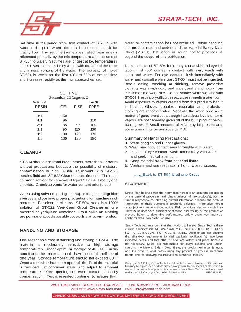
Set time is the period from first contact of ST-504 with water to the point where the mix becomes too thick for gravity flow. The set time (sometimes called foam time) is influenced primarily by the mix temperature and the ratio of ST-504 to water. Set times are longest at low temperatures and ST-504 ratios, and vary a little with the age of the resin and mineral content of the water. The viscosity of mixed ST-504 is lowest for the first 40% to 50% of the set time and increases rapidly as the mix approaches set.
SET TIME Seconds at 20 Degrees C
STRATA-TECH, INC.
moisture contamination has not occurred. Before handling this product, read and understand the Material Safety Data Sheet (MSDS). Instruction in sound safety practices is beyond the scope of this publication.
Direct contact of ST-504 liquid may cause skin and eye irri- tation. If ST-504 comes in contact with skin, wash with soap and water. For eye contact, flush immediately with water and consult a physician. ST-504 must not be ingested. Before eating, smoking or drinking, remove protective clothing, wash with soap and water, and stand away from the immediate work site. Do not smoke while working with ST-504.If respiratory difficulties occur, seek medical attention.
WATER : RESIN
9:1
TACK GEL RISE FREE
150
Avoid exposure to vapors created from this product when it is heated. Gloves, goggles , respirator and protective clothing are recommended. Ventilate the work area as a matter of good practice, although hazardous levels of toxic
4:1 2:1 1:1 1:2 1:3
CLEANUP
95 85 95
100 100
95
110 120 120
110 100 160 170 180
vapors are not generally given off of the bulk product below 90 degrees F. Small amounts of MDI may be present and some users may be sensitive to MDI.
Summary of Handling Precautions: 1. Wear goggles and rubber gloves. 2. Wash any body contact area throughly with water. 3. In case of eye contact, wash immediately with water
and seek medical attention. ST-504 should not stand in equipment more than 12 hours without precautions because the possibility of moisture contamination is high. Flush equipment with ST-590 purging fluid and ST-522 Cleaner soon after use. The most common solvent for removal of liquid ST-504 is methylene chloride. Check solvents for water content prior to use.
When using solvents during cleanup, extinguish all ignition sources and observe proper precautions for handling such materials. For cleanup of cured ST-504, soak in a 100% solution of ST-522 Veri-Kleen Grout Cleaner using a covered polyethylene container. Grout spills on clothing are permanent, so disposable coveralls are recommended.
HANDLING AND STORAGE
Use reasonable care in handling and storing ST-504. The material is moderately sensitive to high storage temperatures. Under optimum storage of 40 - 60 F in dry conditions, the material should have a useful shelf life of one year. Storage temperature should not exceed 80 F. Once a container has been opened, the life of the material is reduced. Let container stand and adjust to ambient temperature before opening to prevent contamination by condensation. Test a resealed container to assure that
4. Keep material away from heat and flame. 5. Ventilate and use respirator in hot or closed spaces.
......_..Back to ST-504 Urethane Grout
STATEMENT
Strata Tech believes that the information herein is an accurate description of the general properties and characteristics of the product(s), but the user is responsible for obtaining current information because the body of knowledge on these subjects is constantly enlarged. Information herein is subject to change without notice. Field conditions also vary wide ly,so users must undertake sufficient verification and testing of the product or process herein to determine performance, safety, usefulness, and suit- ability for their own particular use.
Strata Tech warrants only that the product will meet Strata Tech's then- current specificat ion. NO WARRANTY OF SUITABILITY OR FITNESS FOR A PARTICULAR PURPOSE IS MADE. Users should not assume that all safety requirements for their particular application(s) have been indicated herein and that other or additional actions and precautions are not necessary. Users are responsible for always reading and under- standing the Material Safety Data Sheet, the product technical literature, and the product label before using any product or process mentioned herein and for following the instructions contained therein.
Copyright C 1990 by Strata Tech, Inc. All rights reserved. No part of this publica- tion may be reproduced or disseminated in any form, by any means,or stored in any electronic format without prior written permission from Strata Tech except as allowed under the U.S. Copyright Act, 1976. Printed in USA. REV 9804 15.
3601 104th Street Des Moines, Iowa 50322 PHONE 515/251.7770 FAX 515/251.7705 WEB SITE www.strata-tech .com EMAIL lnfo@strata-tech .com
CHEMICAL SEALANTS • WATER CONTROL MATERIALS • GROUTING EQUIPMENT
STRATA -TECH, INC.
ST-524 POLY-FOAM INJECTION RESIN
INTRODUCTION REACTION
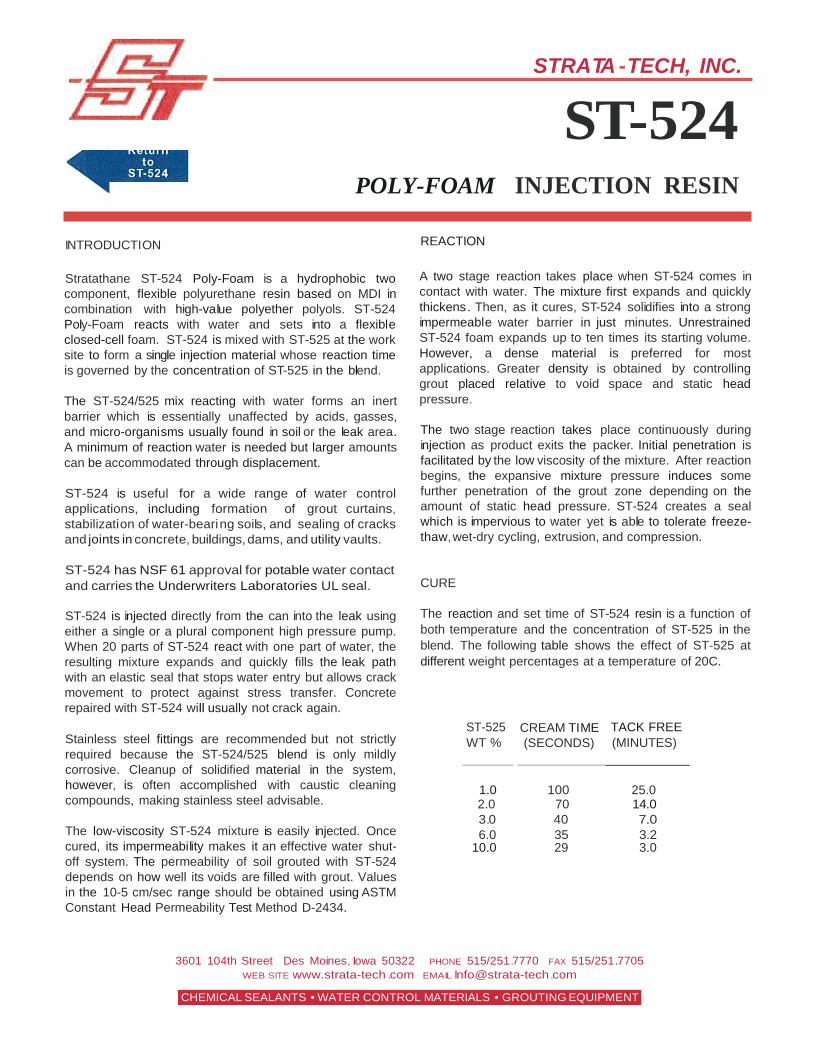
Stratathane ST-524 Poly-Foam is a hydrophobic two component, flexible polyurethane resin based on MDI in combination with high-value polyether polyols. ST-524 Poly-Foam reacts with water and sets into a flexible closed-cell foam. ST-524 is mixed with ST-525 at the work site to form a single injection material whose reaction time is governed by the concentration of ST-525 in the blend.
The ST-524/525 mix reacting with water forms an inert barrier which is essentially unaffected by acids, gasses, and micro-organisms usually found in soil or the leak area. A minimum of reaction water is needed but larger amounts can be accommodated through displacement.
ST-524 is useful for a wide range of water control applications, including formation of grout curtains, stabilization of water-beari ng soils, and sealing of cracks and joints in concrete, buildings, dams, and utility vaults.
ST-524 has NSF 61 approval for potable water contact and carries the Underwriters Laboratories UL seal.
ST-524 is injected directly from the can into the leak using either a single or a plural component high pressure pump. When 20 parts of ST-524 react with one part of water, the resulting mixture expands and quickly fills the leak path with an elastic seal that stops water entry but allows crack movement to protect against stress transfer. Concrete repaired with ST-524 will usually not crack again.
Stainless steel fittings are recommended but not strictly required because the ST-524/525 blend is only mildly corrosive. Cleanup of solidified material in the system, however, is often accomplished with caustic cleaning compounds, making stainless steel advisable.
The low-viscosity ST-524 mixture is easily injected. Once cured, its impermeability makes it an effective water shut- off system. The permeability of soil grouted with ST-524 depends on how well its voids are filled with grout. Values in the 10-5 cm/sec range should be obtained using ASTM Constant Head Permeability Test Method D-2434.
A two stage reaction takes place when ST-524 comes in contact with water. The mixture first expands and quickly thickens. Then, as it cures, ST-524 solidifies into a strong impermeable water barrier in just minutes. Unrestrained ST-524 foam expands up to ten times its starting volume. However, a dense material is preferred for most applications. Greater density is obtained by controlling grout placed relative to void space and static head pressure.
The two stage reaction takes place continuously during injection as product exits the packer. Initial penetration is facilitated by the low viscosity of the mixture. After reaction begins, the expansive mixture pressure induces some further penetration of the grout zone depending on the amount of static head pressure. ST-524 creates a seal which is impervious to water yet is able to tolerate freeze- thaw, wet-dry cycling, extrusion, and compression.
CURE
The reaction and set time of ST-524 resin is a function of both temperature and the concentration of ST-525 in the blend. The following table shows the effect of ST-525 at different weight percentages at a temperature of 20C.
ST-525 WT %
CREAM TIME (SECONDS)
TACK FREE (MINUTES)
1.0
100
25.0
2.0 70 14.0 3.0 40 7.0 6.0 35 3.2
10.0 29 3.0
3601 104th Street Des Moines, Iowa 50322 PHONE 515/251.7770 FAX 515/251.7705 WEB SITE www.strata-tech.com EMAIL lnfo@strata-tech .com
CHEMICAL SEALANTS • WATER CONTROL MATERIALS • GROUTING EQUIPMENT
PHYSICAL CONSTANTS
The primary physical constants for the ST-524 system are shown in the table which follows.
ST-524 ST-525
STRATA-TECH, INC.
For heavy cleaning, push out ST-590 with ST-522 Veri- Kleen Grout Cleaner and follow the instructions for its use. Do not allow ST-590 or ST-522 to remain in the system for long periods. Properly dispose of used cleaning materials and do not reuse if contaminated or resin-loaded. See the pump manuals and the Technical Data Sheet for ST-522 and ST-590 for more information.
ENVIRONMENTAL
Appearance Specific Grav Viscosity Flash Point
Pale Yellow 1.08 20 c 500 cps 25 C >385 c
Greyish Liquid 0.995 at 20 C 25 cps at 25 C 130 c
ST-524 is essentially non-toxic in its cured form, with an LD50 (rat) in excess of 5000 mg/kg. Freezing either the cured or uncured material is not harmful to the product and may prolong the shelf life of the uncured resin in an unopened container. At temperatures below 5 C, crystallization may occur but is reversible without damage
The low viscosity of the ST-524 Resin blend allows good penetration into cavities and cracks. After curing, water pressure will not affect the ST-524 resin seal at heads usually encountered in crack injection repair work. It has no preset "pot life" and does not cure as long as water or moisture vapor are not available to start the cure cycle.
TENSILE AND ELONGATION
Test samples were prepared by putting the reacting mixture into a plastic pressure mold and capping the opening. This procedure (per ASTM D-638) resulted in a closed-cell foam with a density of about 30 pounds per cubic foot as compared to a free rise density of about 6 pounds per cubic foot. Measured tensile strength was about 6 psi at 67% elongation. The samples subsequently showed no water absorption after 4 hour immersion. Flammability tests of the same samples showed that combustion self- extinguished when the flame source was removed.
To prevent condensation from forming on the liquid or in the can, the temperature of the ST-524 should be adjusted to match the ambient temperature of the work area. Protect uncured resin during application from exposure to water, moisture vapor, and direct sunlight.
CLEANUP
Cleanup of ST-524 is accomplished with a solvent or with a solvent and a cleaner used in sequence. The preferred solvent is ST-590 Kleen-Purge and the recommended cleaner is ST-522 Veri-Kleen Grout Cleaner. Use ST-590 for the liquid resin and ST-522 for solidified resin.
to the material by indirectly warming and gently mixing the product.
Stratathane ST-524 contains no measurable amount of TOI as performed by the Modified Analysis for Diisocyanates . ST-524 is non-flammable, non-carcinogenic, and non- corrosive as defined by 40 CFR and as described in the NIOSH Pocket Guide for Hazardous Materials.
....... Back to ST-524 Urethane Grout
STATEMENT
Strata Tech believes that the information herein is an accurate description of the general properties and characteristics of the product(s), but the user is responsible for obtaining current information because the body of knowledge on these subjects is constantly enlarged. Information herein is subject to change without notice. Field conditions also vary widely,so users must undertake sufficient verification and testing of the product or process herein to determine performance, safety, usefulness, and suitability for their own particular use.
Strata Tech warrants only that the product will meet Strata Tech's then- current specification. NO WARRANTY OF SUITABILITY OR FITNESS FOR A PARTICULAR PURPOSE IS MADE. Users should not assume that all safety requirements for their particular application(s) have been indicated herein and that other or additionalactions and precautions are not necessary. Users are responsible for always reading and understanding the Material Safety Data Sheet, the product technical literature, and the product label before using any product or process mentioned herein and for following the instructions contained therein.
Copyright C 1990 by Strata Tech, Inc. All rights reserved. No part of this publ cation may be reproduced or disseminatedin any form, by any means, or stored in any electronic format without prior written permission from Strata Tech except as allowed under the U.S. Copyright Act, 1976. Printed in USA. REV 980415.
3601 104th Street Des Moines, Iowa 50322 PHONE 515/251.7770 FAX 515/251.7705 WEB SITE www.strata-tech .com EMAIL lnfo@strata-tech .com
CHEMICAL SEALANTS • WATER CONTROL MATERIALS • GROUTING EQUIPMENT
Appendix C: Lab Notes & Pictures Raw Laboratory Notes Crack Seal Pictures Visibility Pictures
C-1
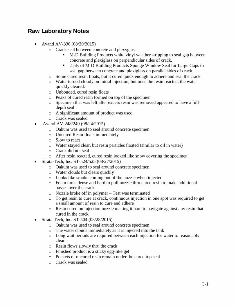
Raw Laboratory Notes
• Avanti AV-330 (08/20/2015) o Crack seal between concrete and plexyglass
M-D Building Products white vinyl weather stripping to seal gap between concrete and plexiglass on perpendicular sides of crack.
2-ply of M-D Building Products Sponge Window Seal for Large Gaps to seal gap between concrete and plexiglass on parallel sides of crack.
o Some cured resin floats, but it cured quick enough to adhere and seal the crack o Water turned cloudy on initial injection, but once the resin reacted, the water
quickly cleared. o Unbonded, cured resin floats o Peaks of cured resin formed on top of the specimen o Specimen that was left after excess resin was removed appeared to have a full
depth seal o A significant amount of product was used. o Crack was sealed
• Avanti AV-248/249 (08/24/2015) o Oakum was used to seal around concrete specimen o Uncured Resin floats immediately o Slow to react o Water stayed clear, but resin particles floated (similar to oil in water) o Crack did not seal o After resin reacted, cured resin looked like snow covering the specimen
• Strata-Tech, Inc. ST-524/525 (08/27/2015) o Oakum was used to seal around concrete specimen o Water clouds but clears quickly o Looks like smoke coming out of the nozzle when injected o Foam turns dense and hard to pull nozzle thru cured resin to make additional
passes over the crack o Nozzle broke off in polymer – Test was terminated o To get resin to cure at crack, continuous injection in one spot was required to get
a small amount of resin to cure and adhere o Resin cured on injection nozzle making it hard to navigate against any resin that
cured in the crack • Strata-Tech, Inc. ST-504 (08/28/2015)
o Oakum was used to seal around concrete specimen o The water clouds immediately as it is injected into the tank o Long wait periods are required between each injection for water to reasonably
clear o Resin flows slowly thru the crack o Finished product is a sticky egg-like gel o Pockets of uncured resin remain under the cured top seal o Crack was sealed
C-2
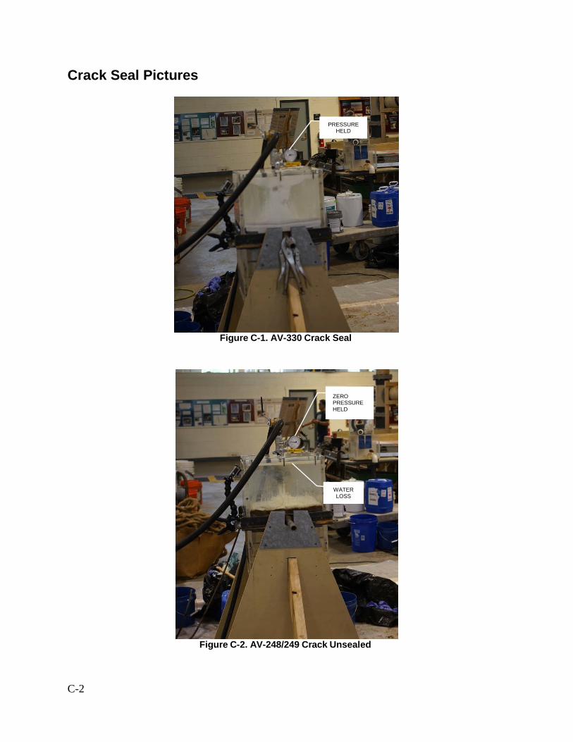
Crack Seal Pictures
Figure C-1. AV-330 Crack Seal
Figure C-2. AV-248/249 Crack Unsealed
ZERO PRESSURE HELD
WATER LOSS
PRESSURE HELD
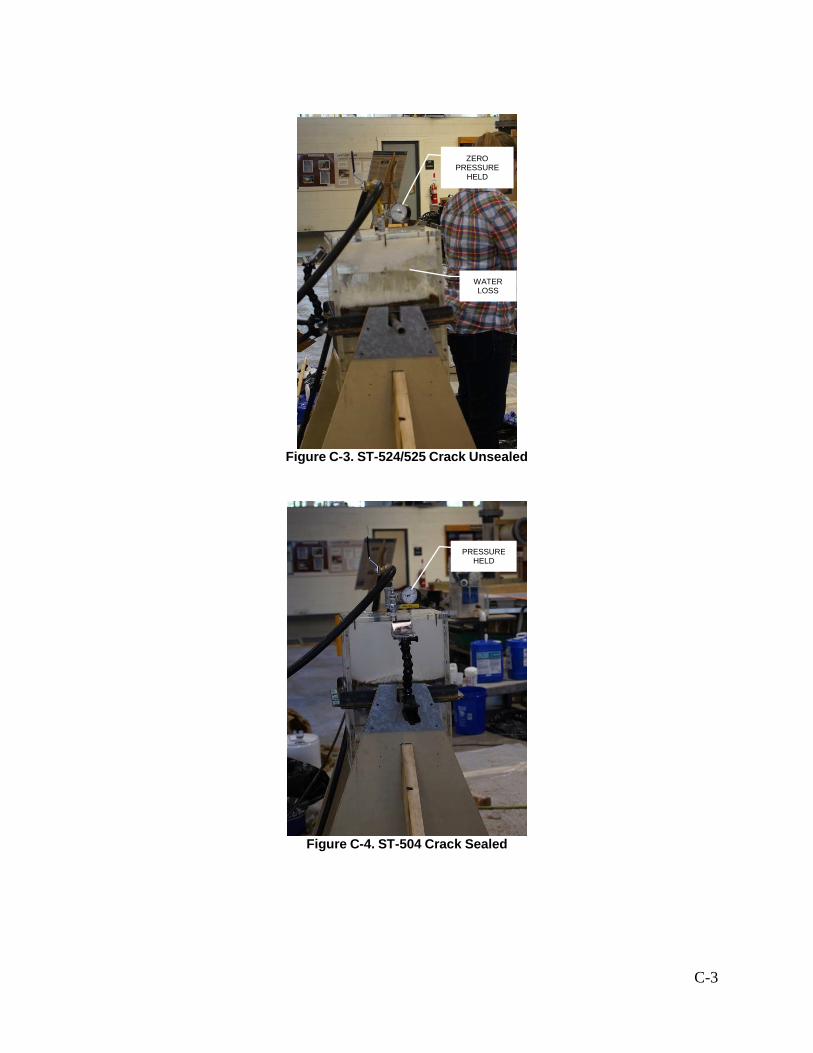
C-3
Figure C-3. ST-524/525 Crack Unsealed
Figure C-4. ST-504 Crack Sealed
PRESSURE HELD
ZERO PRESSURE
HELD
WATER LOSS
C-4
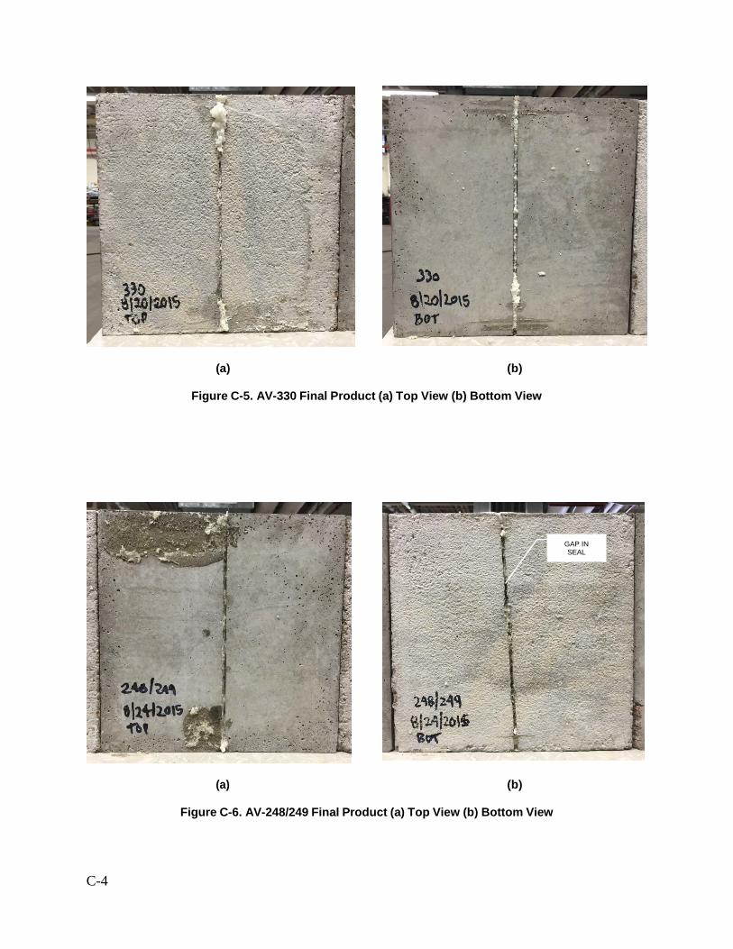
(a) (b)
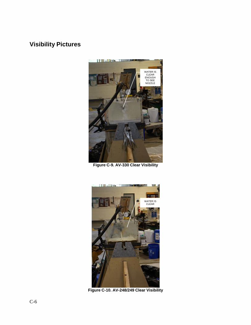
Figure C-5. AV-330 Final Product (a) Top View (b) Bottom View
(a) (b)
Figure C-6. AV-248/249 Final Product (a) Top View (b) Bottom View
GAP IN SEAL
C-5
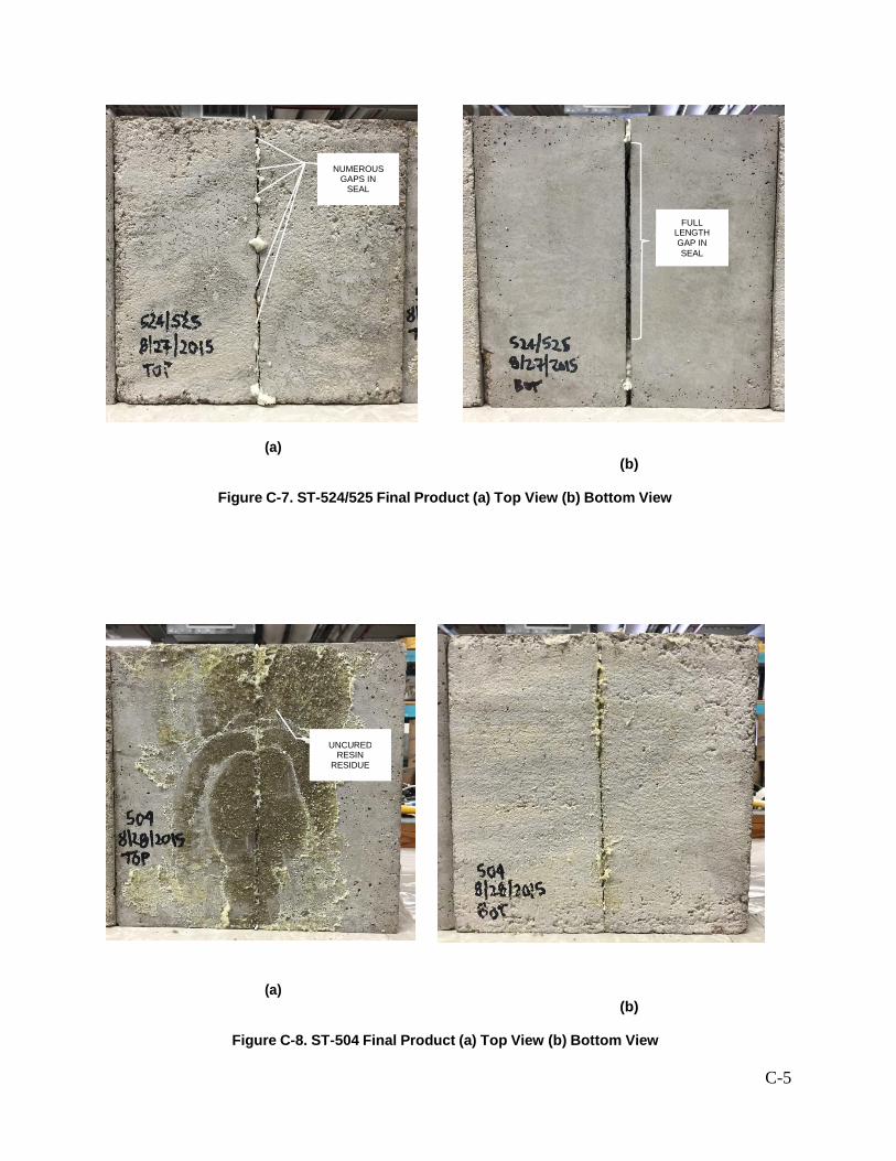
(a) (b)
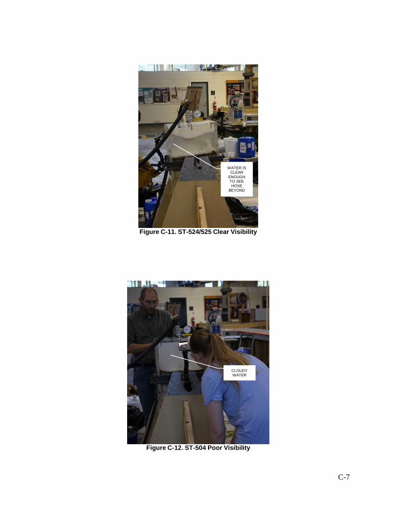
Figure C-7. ST-524/525 Final Product (a) Top View (b) Bottom View
(a) (b)
Figure C-8. ST-504 Final Product (a) Top View (b) Bottom View