Photo from show in 1957. Hartzell developed the first all-fiberglass fan for industrial use, which provided a more chemical resistant and lighter weight material than metal. Hartzell has been manufacturing fiberglass fans for over 50 years!
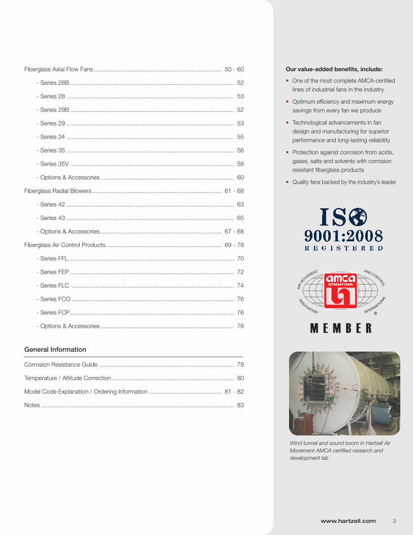
Wind tunnel and sound boom in Hartzell Air Movement AMCA certified research and development lab
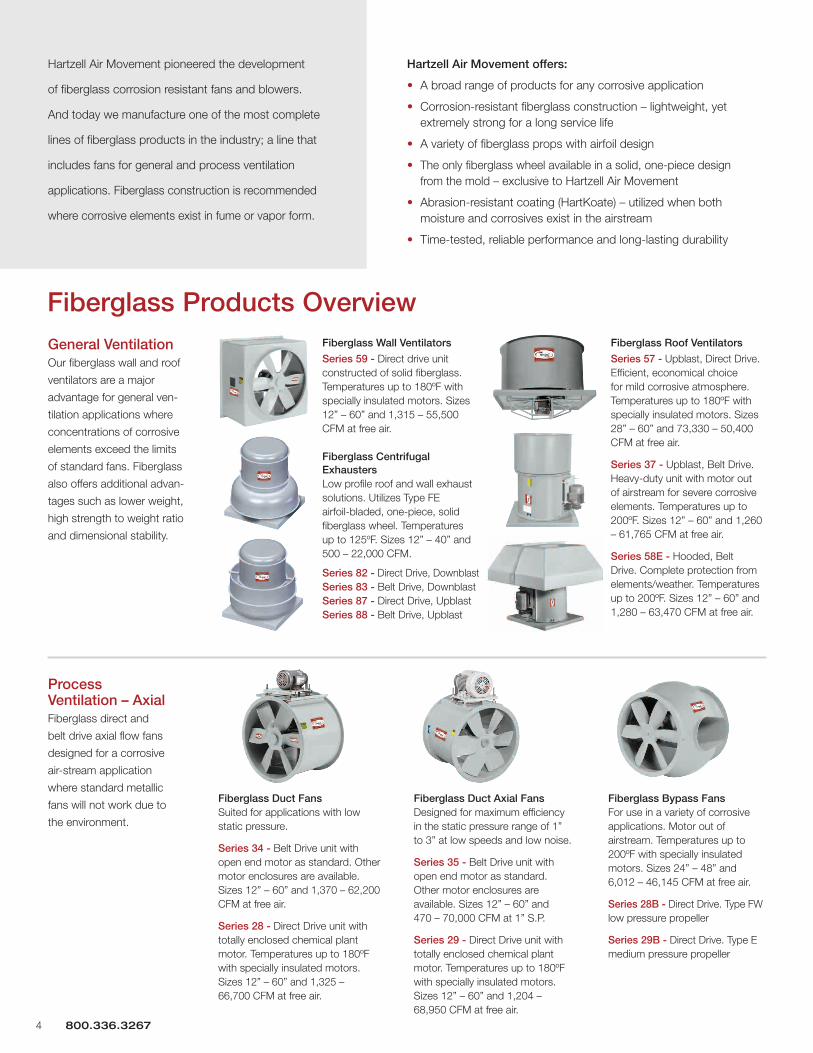
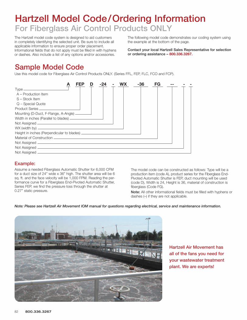
Fiberglass Products Overview
Hartzell Air Movement pioneered the development
of fiberglass corrosion resistant fans and blowers.
And today we manufacture one of the most complete
lines of fiberglass products in the industry; a line that
includes fans for general and process ventilation
applications. Fiberglass construction is recommended
where corrosive elements exist in fume or vapor form.
Hartzell Air Movement offers:
• A broad range of products for any corrosive application
• Corrosion-resistant fiberglass construction – lightweight, yet extremely strong for a long service life
• A variety of fiberglass props with airfoil design
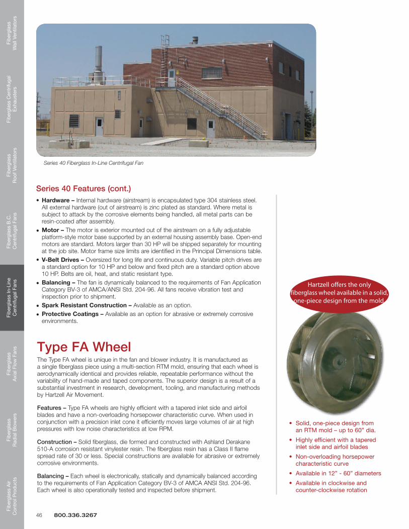
• The only fiberglass wheel available in a solid, one-piece design from the mold – exclusive to Hartzell Air Movement
• Abrasion-resistant coating (HartKoate) – utilized when both moisture and corrosives exist in the airstream
• Time-tested, reliable performance and long-lasting durability
General VentilationOur fiberglass wall and roof
ventilators are a major
advantage for general ven-
tilation applications where
concentrations of corrosive
elements exceed the limits
of standard fans. Fiberglass
also offers additional advan-
tages such as lower weight,
high strength to weight ratio
and dimensional stability.
Process Ventilation – AxialFiberglass direct and
belt drive axial flow fans
designed for a corrosive
air-stream application
where standard metallic
fans will not work due to
the environment.
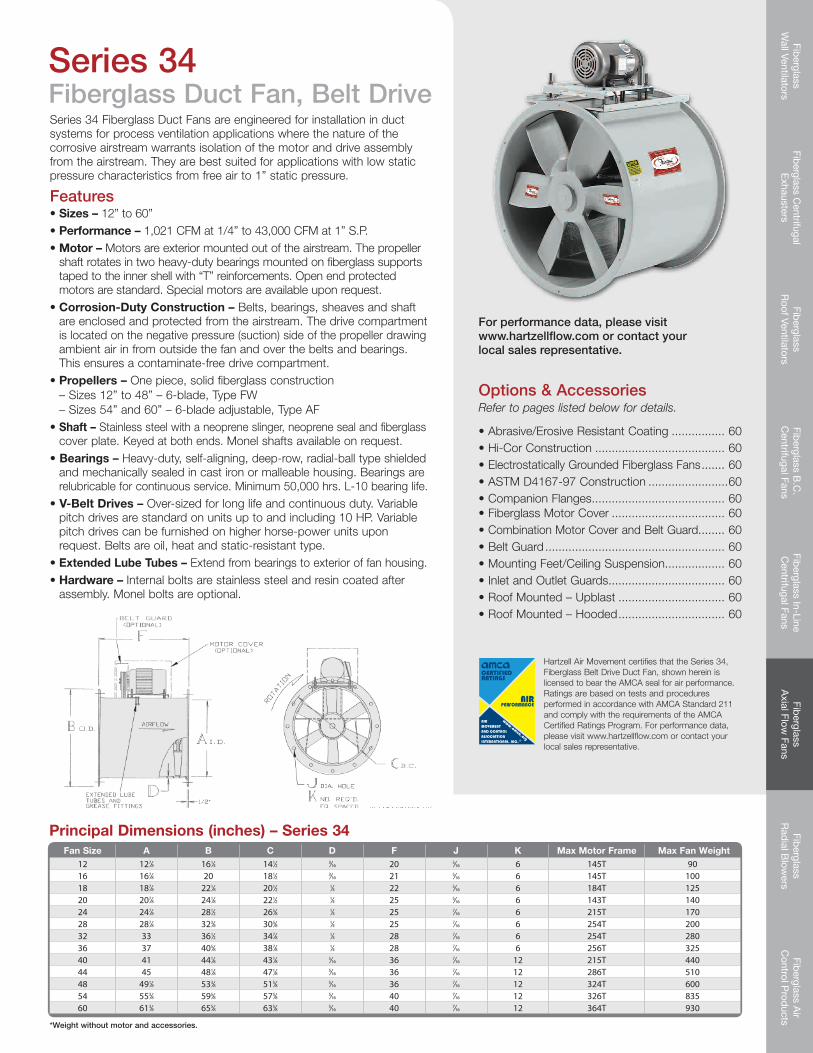
Fiberglass Duct FansSuited for applications with low static pressure.
Series 34 - Belt Drive unit with open end motor as standard. Other motor enclosures are available. Sizes 12” – 60” and 1,370 – 62,200 CFM at free air.
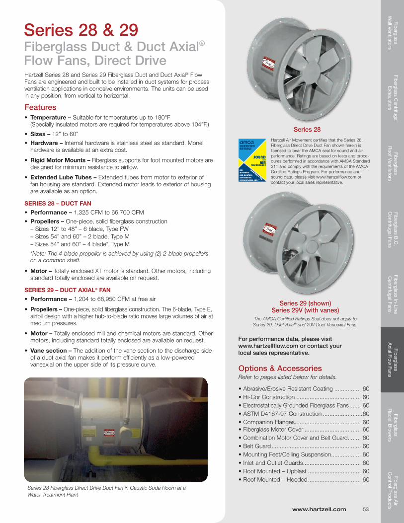
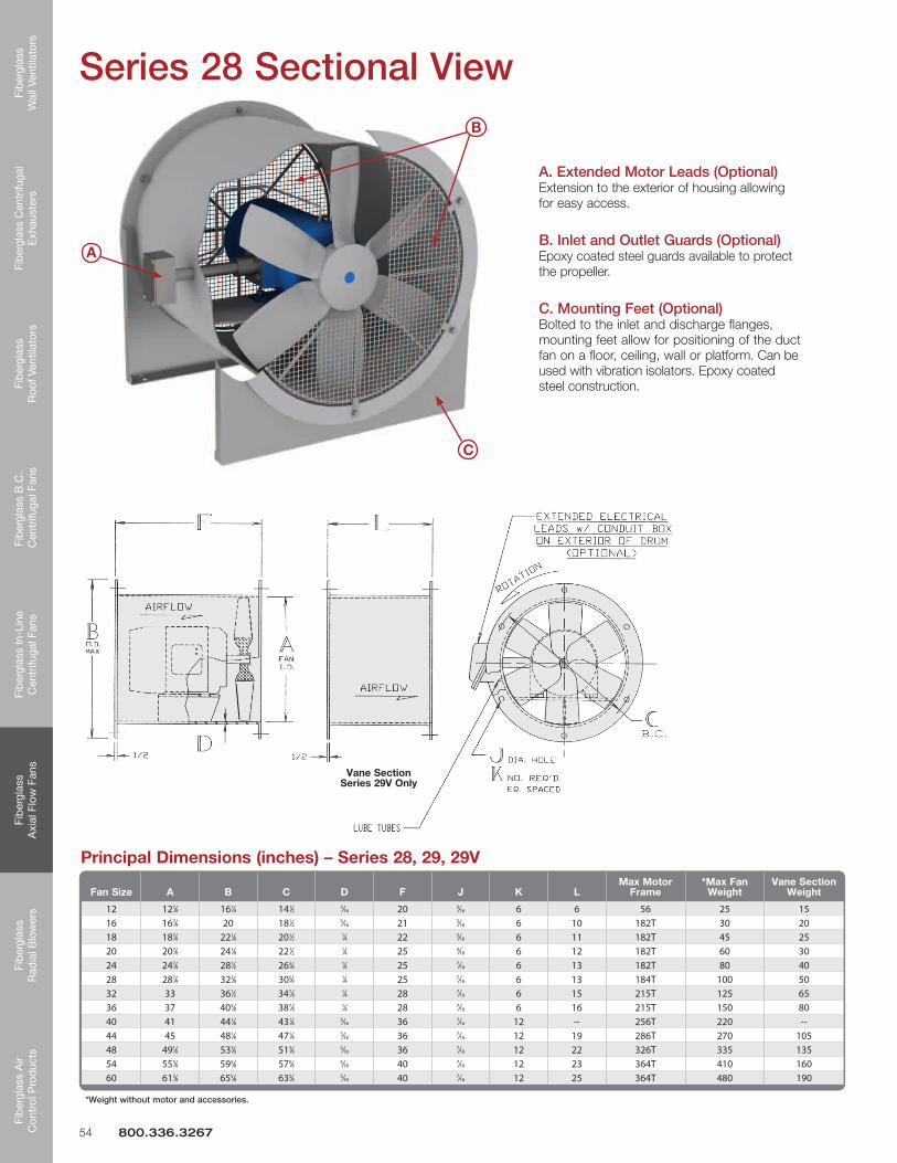
Series 28 - Direct Drive unit with totally enclosed chemical plant motor. Temperatures up to 180ºF with specially insulated motors. Sizes 12” – 60” and 1,325 – 66,700 CFM at free air.
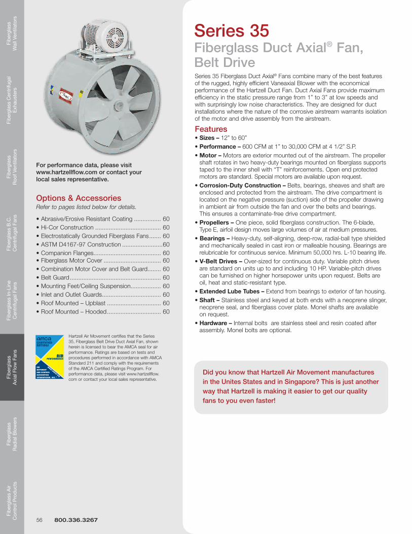
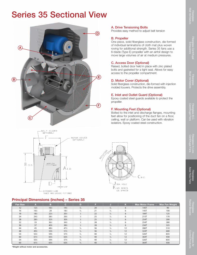
Fiberglass Duct Axial Fans Designed for maximum efficiency in the static pressure range of 1” to 3” at low speeds and low noise.
Series 35 - Belt Drive unit with open end motor as standard. Other motor enclosures are available. Sizes 12” – 60” and 470 – 70,000 CFM at 1” S.P.
Series 29 - Direct Drive unit with totally enclosed chemical plant motor. Temperatures up to 180ºF with specially insulated motors. Sizes 12” – 60” and 1,204 – 68,950 CFM at free air.
Fiberglass Bypass Fans For use in a variety of corrosive applications. Motor out of airstream. Temperatures up to 200ºF with specially insulated motors. Sizes 24” – 48” and 6,012 – 46,145 CFM at free air.
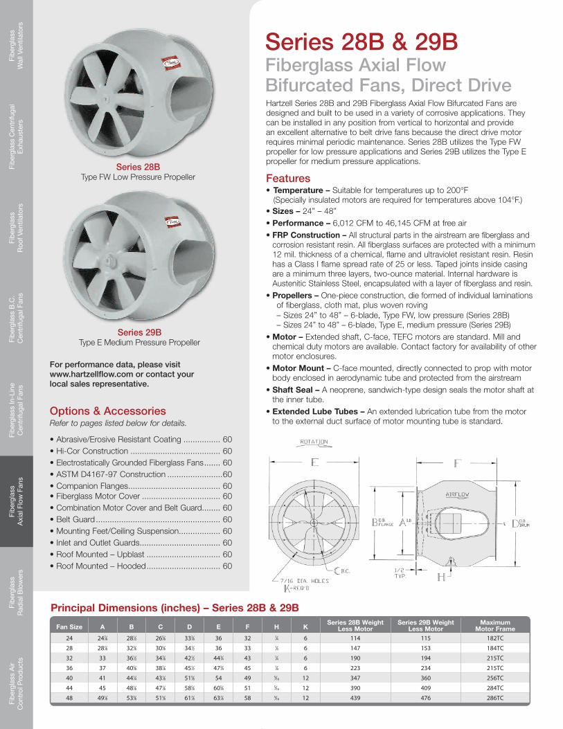
Series 28B - Direct Drive. Type FW low pressure propeller
Series 29B - Direct Drive. Type E medium pressure propeller
4 800.336.3267
Fiberglass Wall Ventilators
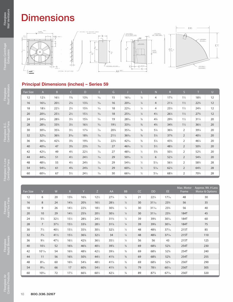
Series 59 - Direct drive unit constructed of solid fiberglass. Temperatures up to 180ºF with specially insulated motors. Sizes 12” – 60” and 1,315 – 55,500 CFM at free air.
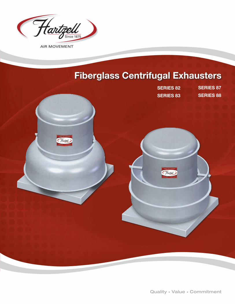
Fiberglass Centrifugal ExhaustersLow profile roof and wall exhaust solutions. Utilizes Type FE airfoil-bladed, one-piece, solid fiberglass wheel. Temperatures up to 125ºF. Sizes 12” – 40” and 500 – 22,000 CFM.
Series 82 - Direct Drive, DownblastSeries 83 - Belt Drive, DownblastSeries 87 - Direct Drive, UpblastSeries 88 - Belt Drive, Upblast
Fiberglass Roof Ventilators
Series 57 - Upblast, Direct Drive. Efficient, economical choice for mild corrosive atmosphere. Temperatures up to 180ºF with specially insulated motors. Sizes 28” – 60” and 73,330 – 50,400 CFM at free air.
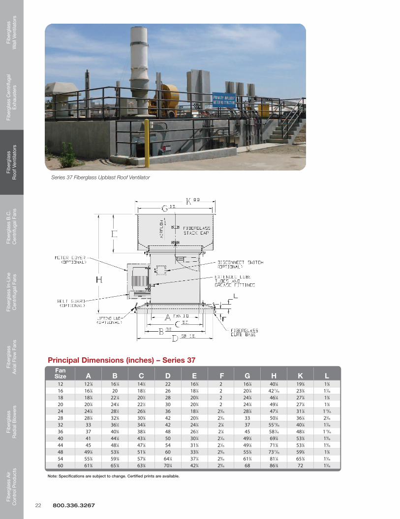
Series 37 - Upblast, Belt Drive. Heavy-duty unit with motor out of airstream for severe corrosive elements. Temperatures up to 200ºF. Sizes 12” – 60” and 1,260 – 61,765 CFM at free air.
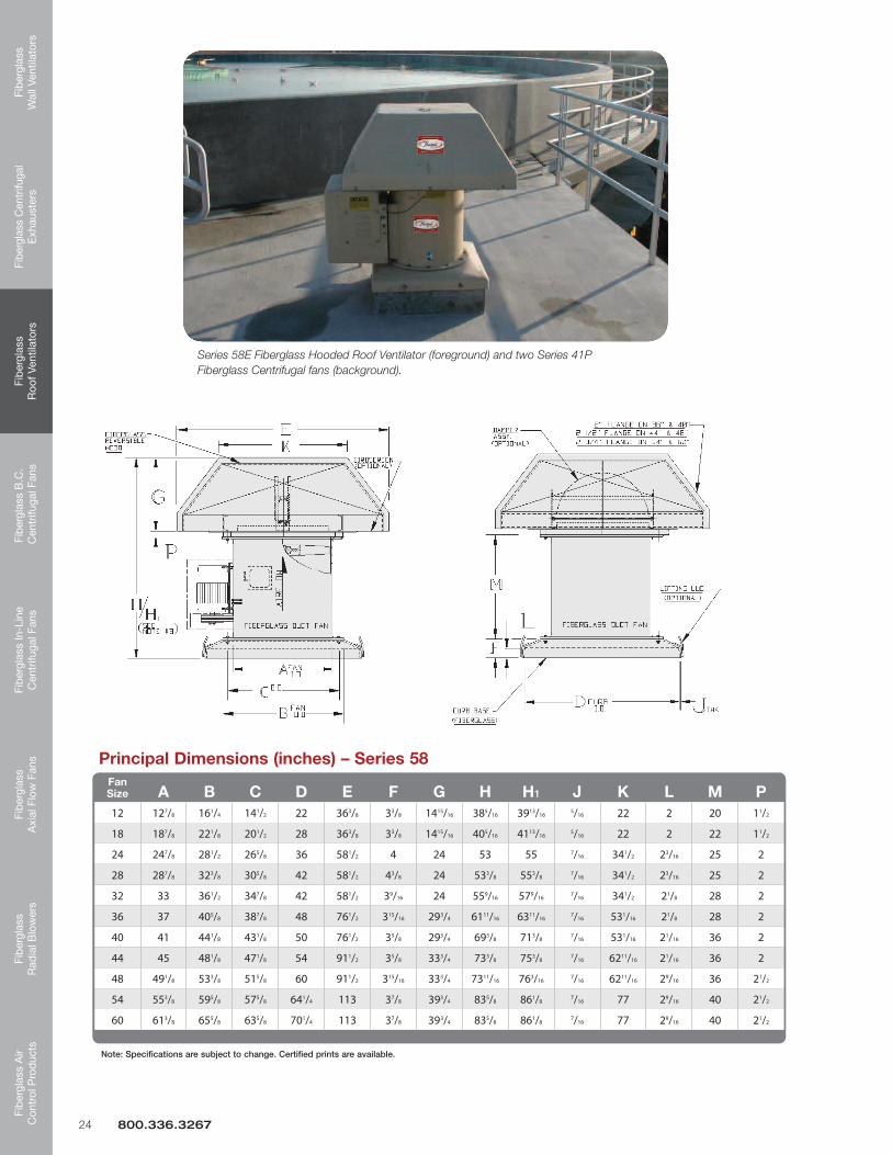
Series 58E - Hooded, Belt Drive. Complete protection from elements/weather. Temperatures up to 200ºF. Sizes 12” – 60” and 1,280 – 63,470 CFM at free air.
www.hartzell.com 5
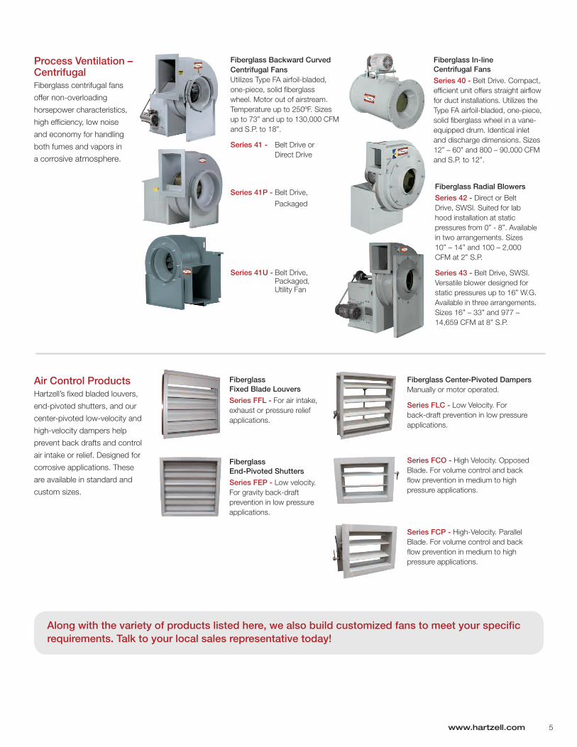
Process Ventilation – CentrifugalFiberglass centrifugal fans
offer non-overloading
horsepower characteristics,
high efficiency, low noise
and economy for handling
both fumes and vapors in
a corrosive atmosphere.
Air Control ProductsHartzell’s fixed bladed louvers,
end-pivoted shutters, and our
center-pivoted low-velocity and
high-velocity dampers help
prevent back drafts and control
air intake or relief. Designed for
corrosive applications. These
are available in standard and
custom sizes.
Fiberglass Backward Curved Centrifugal Fans Utilizes Type FA airfoil-bladed, one-piece, solid fiberglass wheel. Motor out of airstream. Temperature up to 250ºF. Sizes up to 73” and up to 130,000 CFM and S.P. to 18”.
Series 41 - Belt Drive or Direct Drive
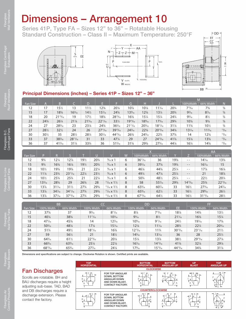
Series 41P - Belt Drive,
Packaged
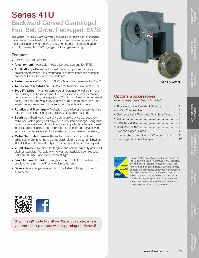
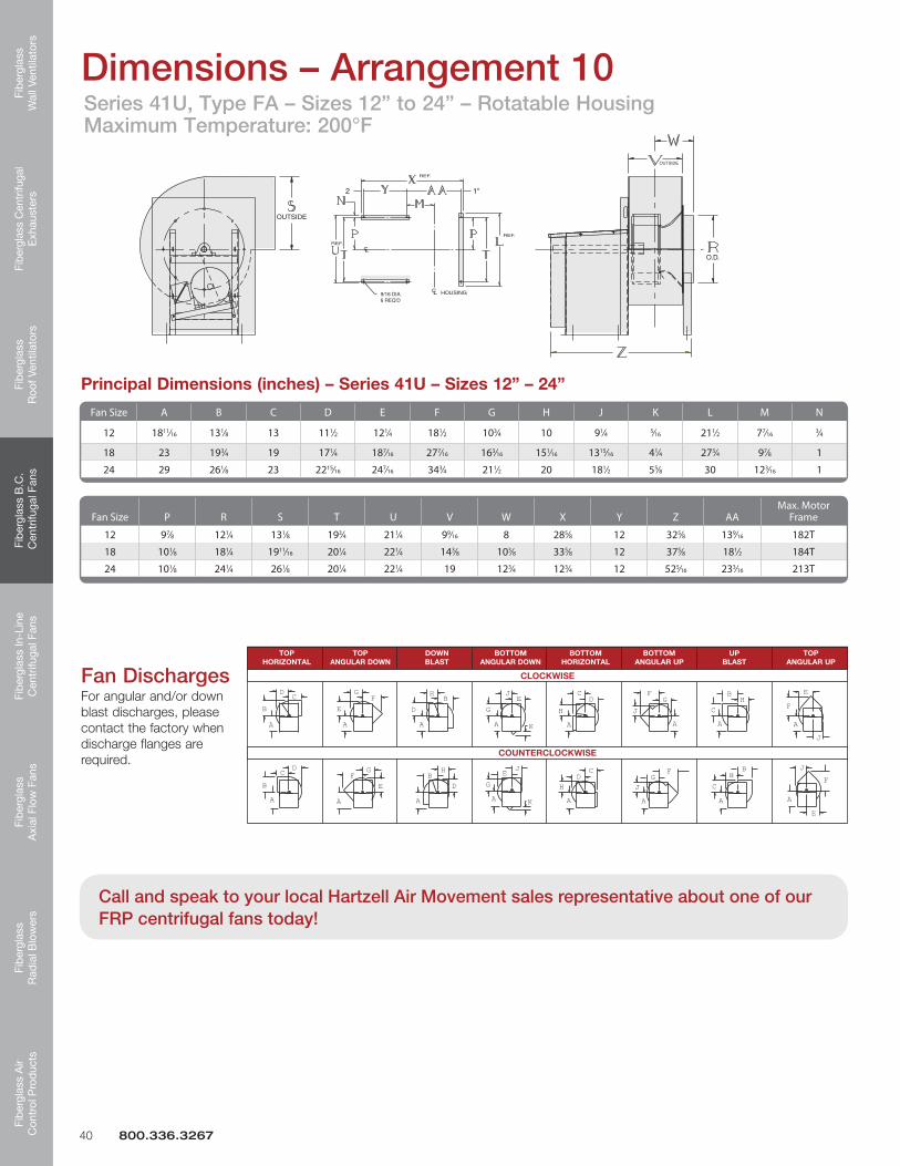
Series 41U - Belt Drive, Packaged, Utility Fan
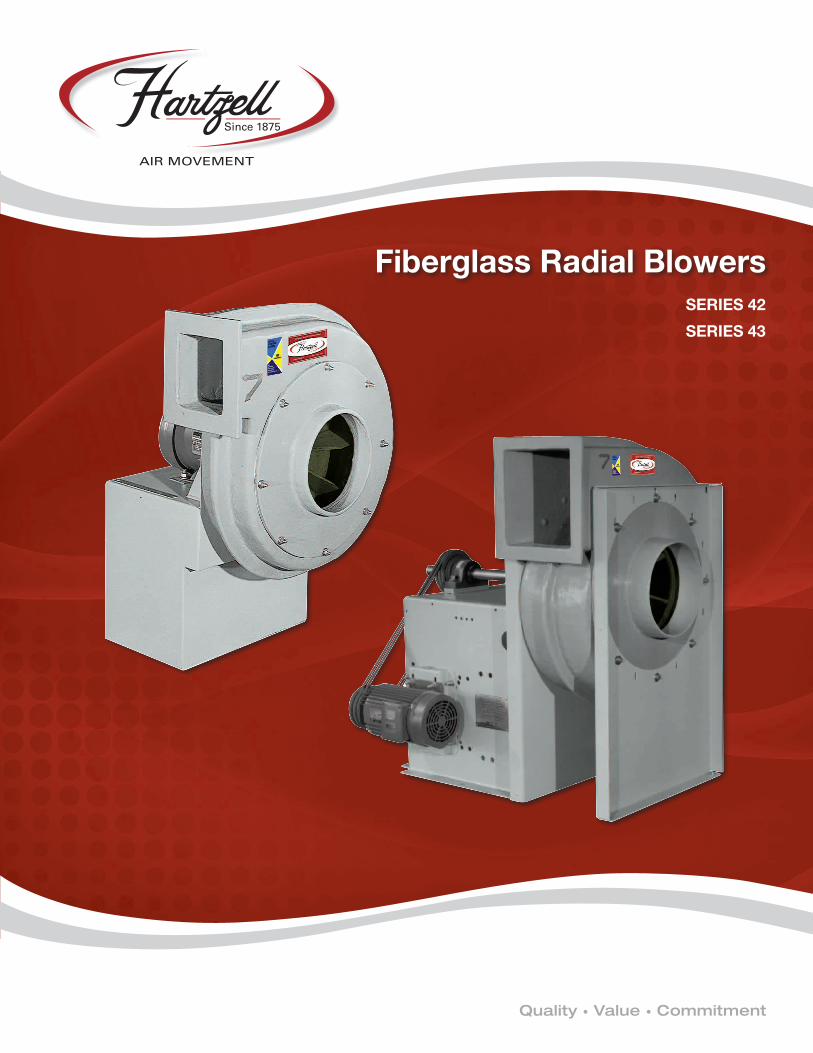
Fiberglass Radial Blowers
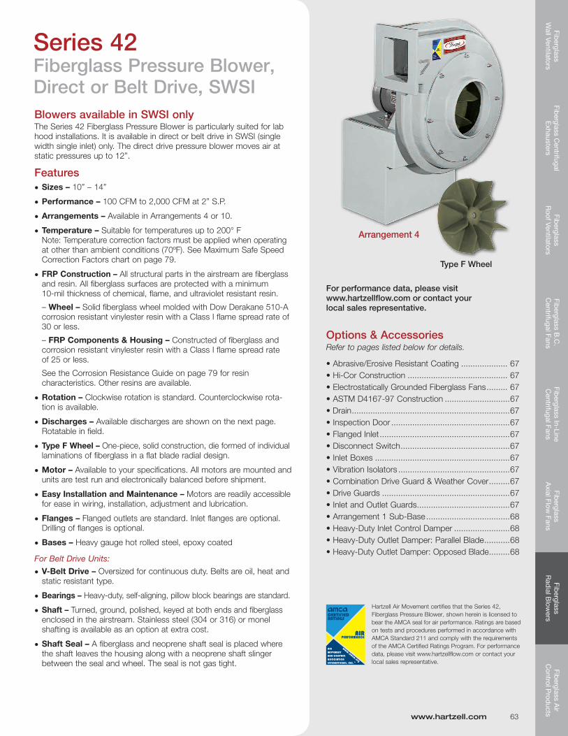
Series 42 - Direct or Belt Drive, SWSI. Suited for lab hood installation at static pressures from 0” - 8”. Available in two arrangements. Sizes 10” – 14” and 100 – 2,000 CFM at 2” S.P.
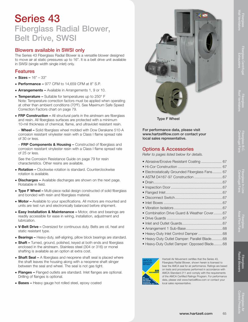
Series 43 - Belt Drive, SWSI.Versatile blower designed for static pressures up to 16” W.G. Available in three arrangements. Sizes 16” – 33” and 977 – 14,659 CFM at 8” S.P.
Fiberglass In-line Centrifugal Fans
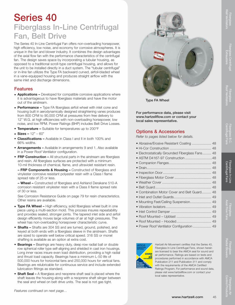
Series 40 - Belt Drive. Compact, efficient unit offers straight airflow for duct installations. Utilizes the Type FA airfoil-bladed, one-piece, solid fiberglass wheel in a vane-equipped drum. Identical inlet and discharge dimensions. Sizes 12” – 60” and 800 – 90,000 CFM and S.P. to 12”.
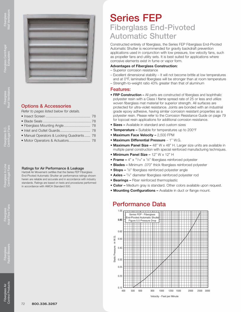
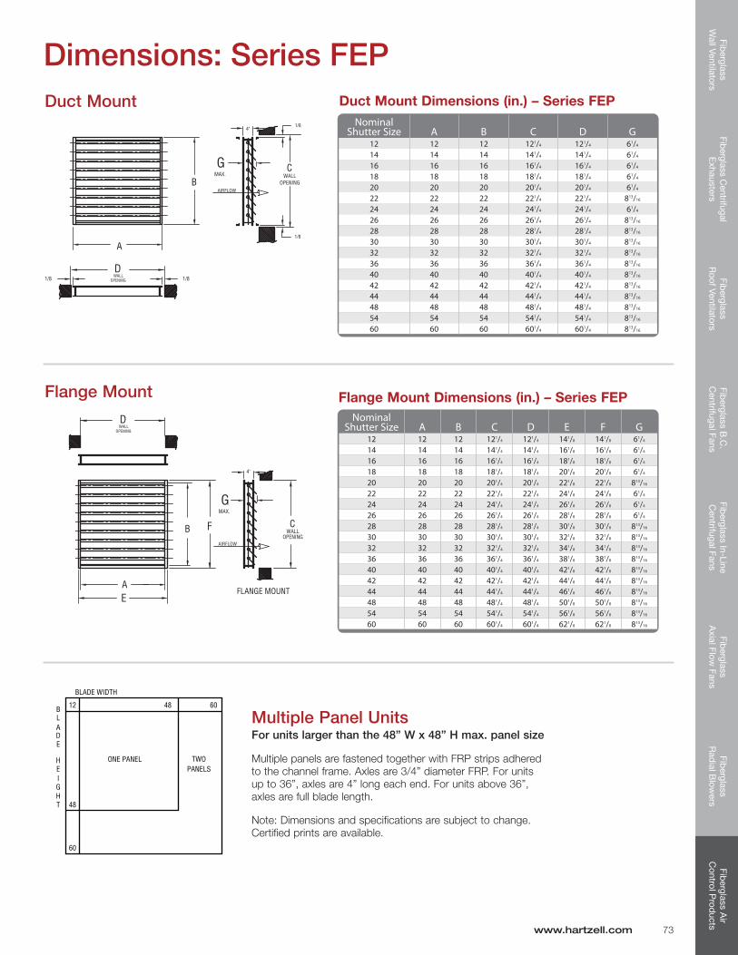
Fiberglass End-Pivoted Shutters
Series FEP - Low velocity. For gravity back-draft prevention in low pressure applications.
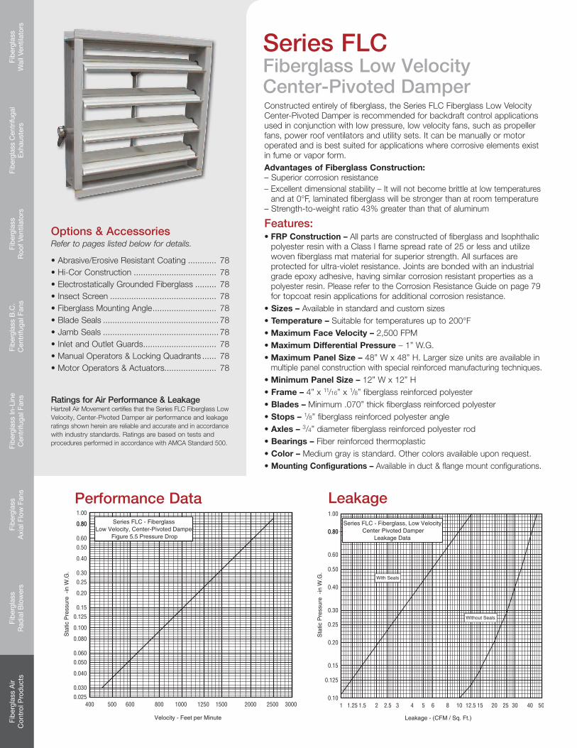
Fiberglass Center-Pivoted DampersManually or motor operated.
Series FLC - Low Velocity. For back-draft prevention in low pressure applications.
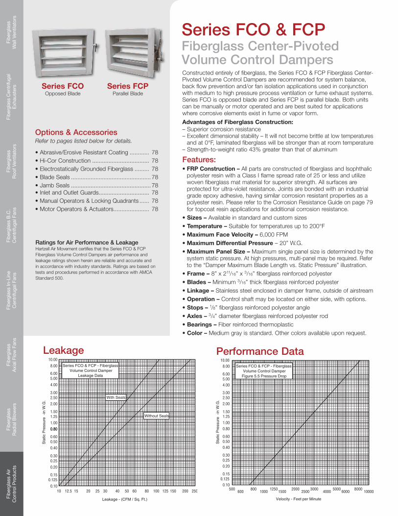
Series FCO - High Velocity. Opposed Blade. For volume control and back flow prevention in medium to high pressure applications.
Series FCP - High-Velocity. Parallel Blade. For volume control and back flow prevention in medium to high pressure applications.
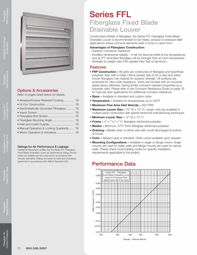
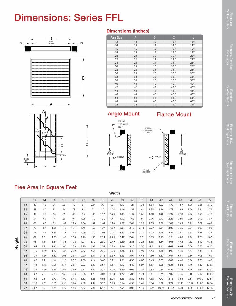
Fiberglass Fixed Blade Louvers
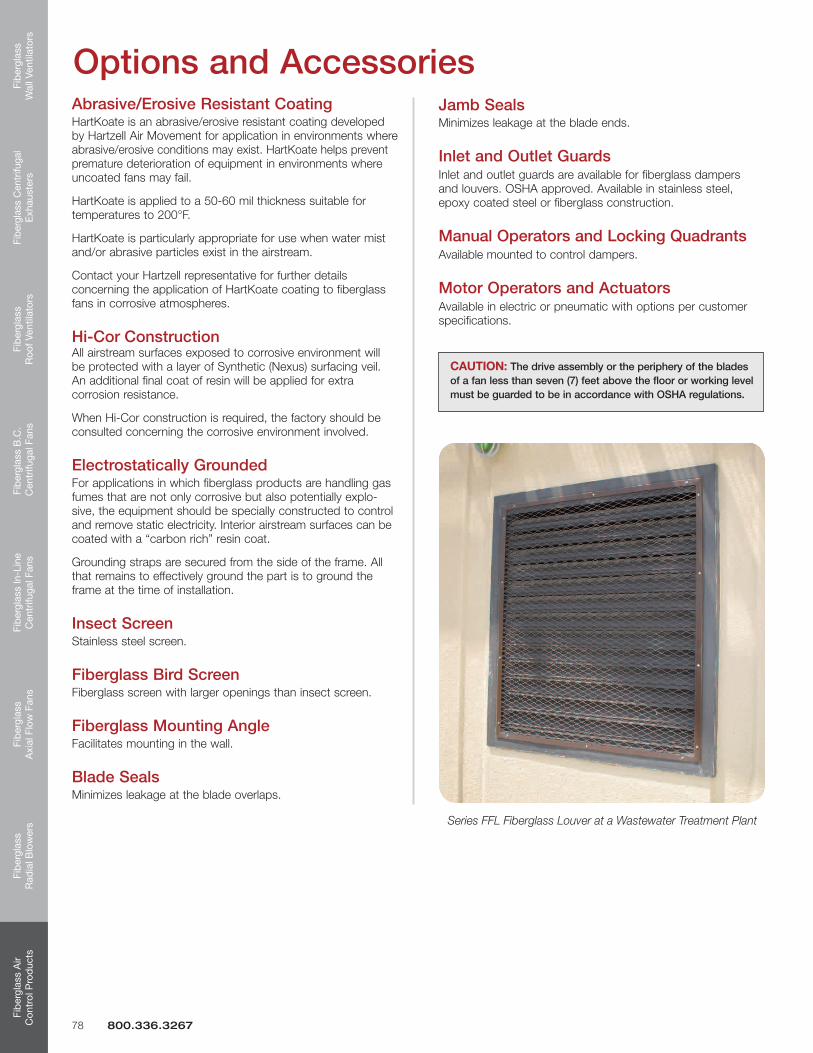
Series FFL - For air intake, exhaust or pressure relief applications.
Along with the variety of products listed here, we also build customized fans to meet your specific requirements. Talk to your local sales representative today!
6 800.336.3267
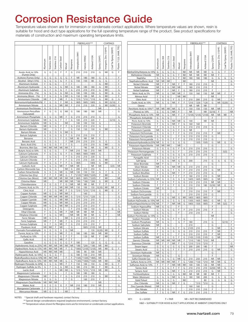
Advantages of Fiberglass ConstructionA variety of corrosion problems plague the water and wastewater industry. Although fans and blowers made of coated steel or metals such as stainless, Hastelloy and monel can handle some of these challenges, Hartzell’s fiberglass products provide unsurpassed resistance to a great majority of corrosive elements at a cost substantially below that of corrosion resistant metals. Please refer to the Corrosion Resistance Guide on page 79 for information on specific chemicals and temperature limitations.
Apart from the primary consideration that fiberglass offers superior corrosion resistant properties, fiberglass also offers these additional advantages:
• Weighs25%-50%lessthancomparableequipmentmade of metal alloys
• Hasanextremelyhighstrength-to-weightratio,strongerthan steel on a per-pound basis
• Thedimensionalstabilityisexcellent
• Willnotbecomebrittleatlowtemperaturesandat-40°F laminated fiberglass will be stronger than at room temperature
•OffersadistinctpriceadvantageoverstainlessandMonel (as much as 1/3 in original cost)
•Hasalongerservicelifeandrequireslessmaintenance
•Offersweather-resistantcharacteristics–itwillnottarnish and will never need painting
•Isextremelydurableandhighlyresistanttoimpact
When optional surface veil, electrical grounding and dynamic balancing are applied, Hartzell Air Movement conforms to ASTM D4167-97 and ASTM E84-2008 Standard Specifications for Fiber-Reinforced Plastic (FRP) Fans and Blowers.
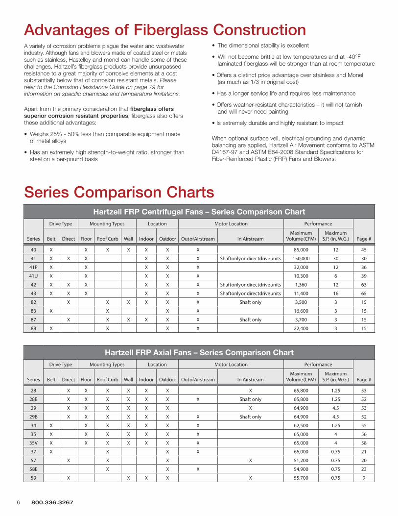
Series Comparison Charts
Hartzell FRP Axial Fans – Series Comparison Chart
Series
Drive Type Mounting Types Location Motor Location Performance
Page #Belt Direct Floor Roof Curb Wall Indoor Outdoor Out of Airstream In AirstreamMaximum
Volume (CFM)Maximum
S.P. (in. W.G.)
28 X X X X X X X 65,800 1.25 53
28B X X X X X X X Shaft only 65,800 1.25 52
29 X X X X X X X 64,900 4.5 53
29B X X X X X X X Shaft only 64,900 4.5 52
34 X X X X X X X 62,500 1.25 55
35 X X X X X X X 65,000 4 56
35V X X X X X X X 65,000 4 58
37 X X X X 66,000 0.75 21
57 X X X X 51,200 0.75 20
58E X X X 54,900 0.75 23
59 X X X X X 55,700 0.75 9
Hartzell FRP Centrifugal Fans – Series Comparison Chart
Series
Drive Type Mounting Types Location Motor Location Performance
Page #Belt Direct Floor Roof Curb Wall Indoor Outdoor Out of Airstream In AirstreamMaximum
Volume (CFM)Maximum
S.P. (in. W.G.)
40 X X X X X X X 85,000 12 45
41 X X X X X X Shaft only on direct drive units 150,000 30 30
41P X X X X X 32,000 12 36
41U X X X X X 10,300 6 39
42 X X X X X X Shaft only on direct drive units 1,360 12 63
43 X X X X X X Shaft only on direct drive units 11,400 16 65
82 X X X X X X Shaft only 3,500 3 15
83 X X X X 16,600 3 15
87 X X X X X X Shaft only 3,700 3 15
88 X X X X 22,400 3 15
Basics of Fan SelectionThe first consideration in any fan selection is the amount of air to be moved and the resistance to this air movement. With specific performance and application criteria in mind, propeller and centrifugal fan selections typically require decisions based on the following criteria.
Belt Drive vs. Direct DriveBelt drive fans offer the ability to adjust fan speed for system balancing if necessary. They also offer more flexibility in speeds and motor selections. In a cost comparison, belt drive fans are typically less costly than comparable size direct drive fans with low speed motors.
Direct drive fans are often preferred for jobs where maintenance access is difficult. Maintenance costs are generally lower with direct drive fans since there are no belts or bearings to replace and no pulleys to adjust.
Larger Fans vs. Smaller FansIn most applications, several fans may meet the specified airflow and pressure requirements. Just as larger fans tend to turn slower and generate less sound, they also tend to have higher initial costs but lower operating costs. Smaller fans have more stable performance curves, lower initial costs, higher sound levels and higher operating costs because of their higher speeds.
Low Sound vs. High Static PressureFans selected for high static pressures run at higher speeds and produce higher tip speeds resulting in higher sound levels. Conversely, in low pressure applications fans generally run at lower speeds, produce lower noise levels and are recommended for sound sensitive applications.
How Accessories Affect Static PressureAll accessory losses must be accounted for when calculating the static pressure load for a fan. For example, when fans are used in conjunction with properly applied accessories, lower pressure capabilities can be specified.
When fans are over-specified to compensate for losses that do not actually exist, both cost and sound levels can be higher than necessary. This most commonly results from larger motors and higher tip speeds.
Motor Service FactorSome motors are cooled by the airstream. With an uninterrupted flow of cooling air, motors may be operated in their service factor range(upto15%abovethemotornameplatehorsepowerwithout damage due to overheating. Less overloads are recommended for applications using totally enclosed or explosion resistant motors.
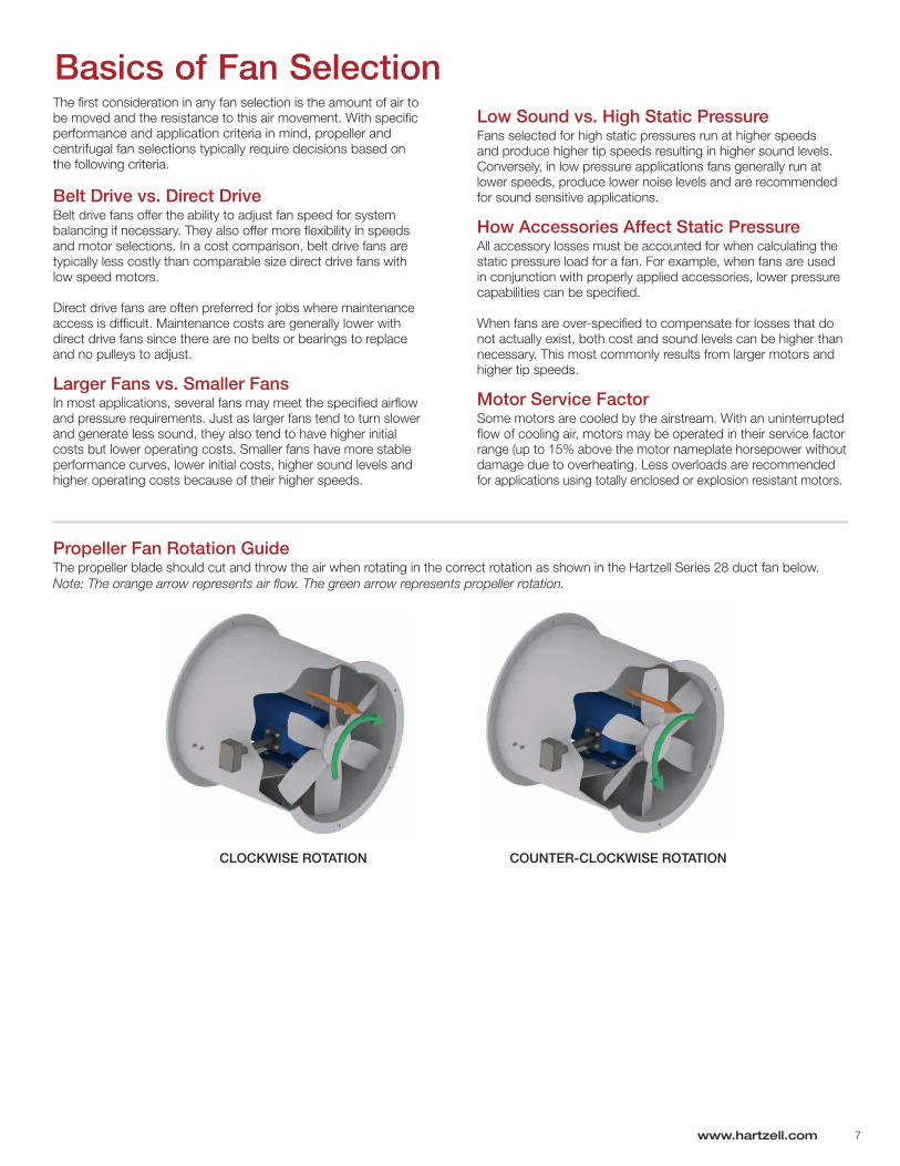
Propeller Fan Rotation GuideThe propeller blade should cut and throw the air when rotating in the correct rotation as shown in the Hartzell Series 28 duct fan below. Note: The orange arrow represents air flow. The green arrow represents propeller rotation.
www.hartzell.com 7
CLOCKWISE ROTATION COUNTER-CLOCKWISE ROTATION
Quality • Value • Commitment
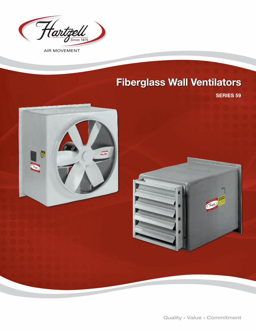
SERIES 59
Fiberglass Wall Ventilators
Fiberglass
Wall Ventilators
Fiberglass Centrifugal
Exhausters
Fiberglass
Roof Ventilators
Fiberglass B
.C.
Centrifugal Fans
Fiberglass In-Line
Centrifugal Fans
Fiberglass
Axial Flow
FansFib
erglass R
adial B
lowers
Fiberglass A
ir C
ontrol Prod
ucts
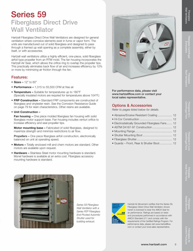
Hartzell Fiberglass Direct Drive Wall Ventilators are designed for general ventilation where corrosive elements exist in fume or vapor form. The units are manufactured out of solid fiberglass and designed to pass through a framed up wall opening as a complete assembly, either by itself, or with accessories.
Hartzell wall ventilators utilize a highly efficient, one-piece, solid fiberglass airfoil type propeller from an RTM mold. The fan housing incorporates the Hartzell Air Seal, which allows the orifice ring to overlap the propeller tips. Thispracticallyeliminatesbackflowofairandincreasesefficiencyby10%or more by minimizing air friction through the fan.
•FRPConstruction– Standard FRP components are constructed of fiberglass and vinylester resin. See the Corrosion Resistance Guide on page 79 for resin characteristics. Other resins are available.
•UnitConstruction–
Fan housing – One piece molded fiberglass fan housing with solid fiberglass motor support base. Fan housing includes venturi orifice to increase efficiency and seal propeller tips.
Motor mounting base – Fabricated of solid fiberglass, designed to maximize strength and minimize restrictions to air flow.
Propellers – One piece fiberglass airfoil construction, electronically balanced on unit at operating speed.
•Motors–Totally enclosed mill and chem motors are standard. Other motors are available upon request.
•Hardware–Stainless Steel motor mounting hardware is standard. Monel hardware is available at an extra cost. Fiberglass accessory mounting hardware is standard.
Hartzell Air Movement certifies that the Series 59, Fiberglass Direct Drive Wall Ventilator shown herein is licensed to bear the AMCA Seal for air performance. Ratings are based on tests and procedures performed in accordance with AMCA Standard 211 and comply with the requirements of the Certified Ratings Program. For performance data, please visit www.hartzellflow.com or contact your local sales representative.
Options & AccessoriesRefer to pages listed below for details.
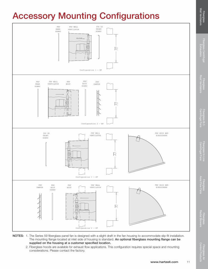
1. The Series 59 fiberglass panel fan is designed with a slight draft in the fan housing to accommodate slip-fit installation. The mounting flange located at inlet side of housing is standard. An optional fiberglass mounting flange can be supplied on the housing at a customer specified location.
2. Fiberglass hoods are available for exhaust flow applications. This configuration requires special space and mounting considerations. Please contact the factory.
Fib
ergl
ass
Wal
l Ven
tilat
ors
Fibe
rgla
ss C
entr
ifuga
l E
xhau
ster
sFi
ber
glas
s R
oof V
entil
ator
sFi
ber
glas
s B
.C.
Cen
trifu
gal F
ans
Fib
ergl
ass
In-L
ine
Cen
trifu
gal F
ans
Fib
ergl
ass
Axi
al F
low
Fan
sFi
ber
glas
s R
adia
l Blo
wer
sFi
ber
glas
s A
ir C
ontr
ol P
rod
ucts
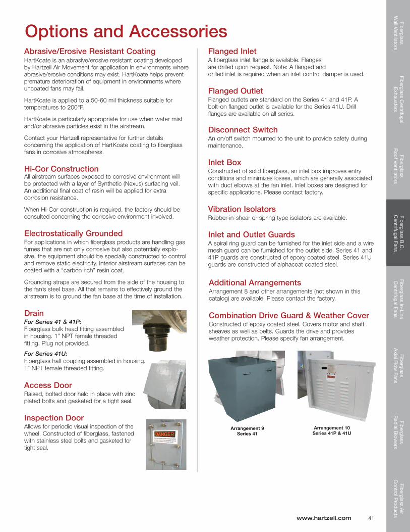
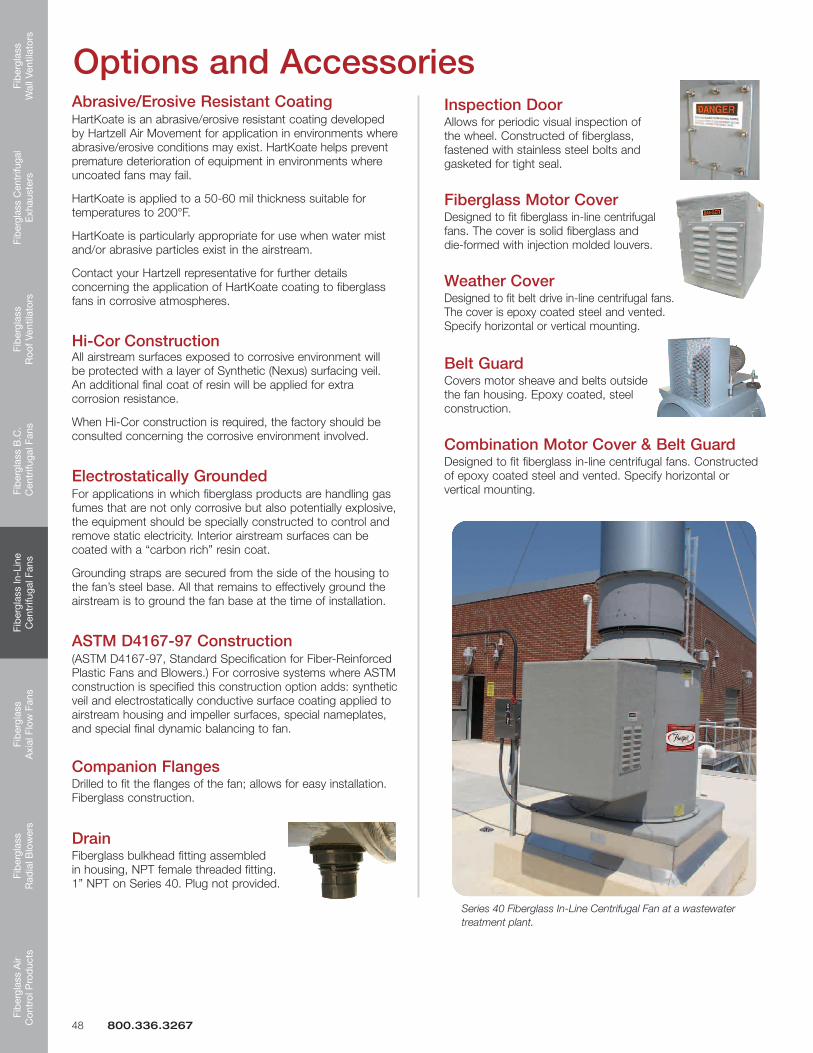
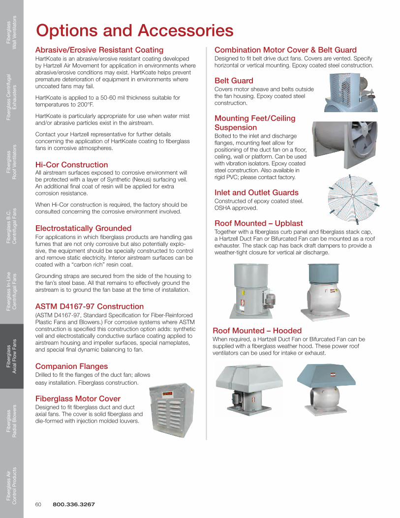
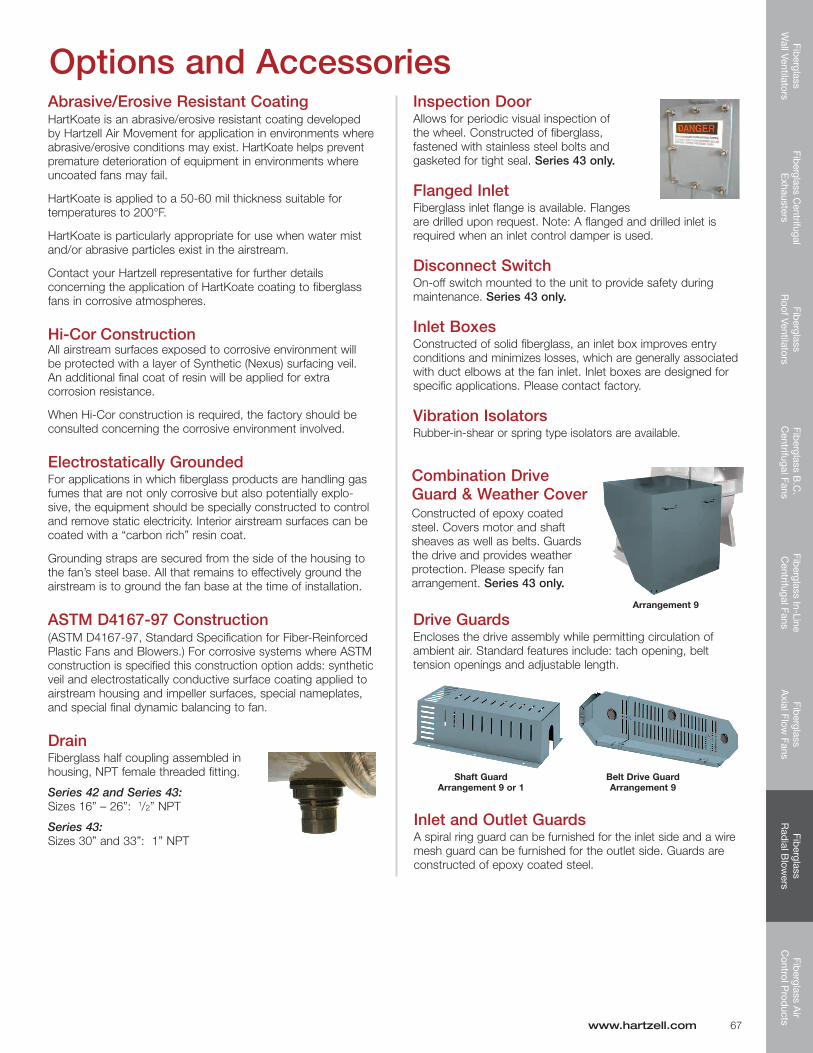
Options and AccessoriesAbrasive/Erosive Resistant CoatingHartKoate is an abrasive/erosive resistant coating developed by Hartzell Air Movement for application in environments where abrasive/erosive conditions may exist. HartKoate helps prevent premature deterioration of equipment in environments where uncoated fans may fail.
HartKoate is applied to a 50-60 mil thickness suitable for temperaturesto200°F.
HartKoate is particularly appropriate for use when water mist and/or abrasive particles exist in the airstream.
Contact your Hartzell representative for further details concerning the application of HartKoate coating to fiberglass fans in corrosive atmospheres.
Hi-Cor ConstructionAll airstream surfaces exposed to corrosive environment will be protected with a layer of Synthetic (Nexus) surfacing veil. An additional final coat of resin will be applied for extra corrosion resistance.
When Hi-Cor construction is required, the factory should be consulted concerning the corrosive environment involved.
Electrostatically GroundedFor applications in which fiberglass products are handling gas fumes that are not only corrosive but also potentially explo-sive, the equipment should be specially constructed to control and remove static electricity. Interior airstream surfaces can be coated with a “carbon rich” resin coat.
Grounding straps are secured from the side of the housing to the fan’s steel base. All that remains to effectively ground the airstream is to ground the fan base at the time of installation.
ASTM D4167-97 Construction(ASTM D4167-97, Standard Specification for Fiber-Reinforced Plastic Fans and Blowers.) For corrosive systems where ASTM construction is specified this construction option adds: synthetic veil and electrostatically conductive surface coating applied to airstream housing and impeller surfaces, special nameplates, and special final dynamic balancing to fan.
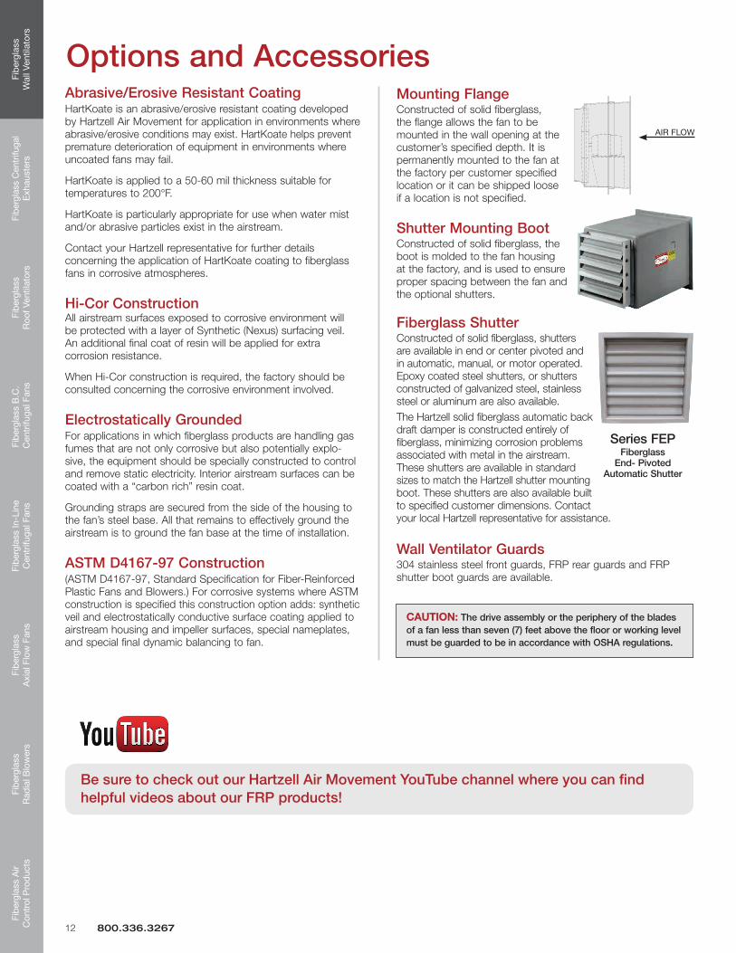
Mounting FlangeConstructed of solid fiberglass, the flange allows the fan to be mounted in the wall opening at the customer’s specified depth. It is permanently mounted to the fan at the factory per customer specified location or it can be shipped loose if a location is not specified.
Shutter Mounting BootConstructed of solid fiberglass, the boot is molded to the fan housing at the factory, and is used to ensure proper spacing between the fan and the optional shutters.
Fiberglass ShutterConstructed of solid fiberglass, shutters are available in end or center pivoted and in automatic, manual, or motor operated. Epoxy coated steel shutters, or shutters constructed of galvanized steel, stainless steel or aluminum are also available. The Hartzell solid fiberglass automatic back draft damper is constructed entirely of fiberglass, minimizing corrosion problems associated with metal in the airstream. These shutters are available in standard sizes to match the Hartzell shutter mounting boot. These shutters are also available built to specified customer dimensions. Contact your local Hartzell representative for assistance.
Wall Ventilator Guards304 stainless steel front guards, FRP rear guards and FRP shutter boot guards are available.
AIR FLOWAIR FLOW
Series FEP Fiberglass
End- Pivoted Automatic Shutter
CAUTION: The drive assembly or the periphery of the blades of a fan less than seven (7) feet above the floor or working level must be guarded to be in accordance with OSHA regulations.
12 800.336.3267
Be sure to check out our Hartzell Air Movement YouTube channel where you can find helpful videos about our FRP products!
Quality • Value • Commitment
SERIES 87
SERIES 88
Fiberglass Centrifugal ExhaustersSERIES 82
SERIES 83
Fib
ergl
ass
Wal
l Ven
tilat
ors
Fibe
rgla
ss C
entr
ifuga
l E
xhau
ster
sFi
ber
glas
s R
oof V
entil
ator
sFi
ber
glas
s B
.C.
Cen
trifu
gal F
ans
Fib
ergl
ass
In-L
ine
Cen
trifu
gal F
ans
Fib
ergl
ass
Axi
al F
low
Fan
sFi
ber
glas
s R
adia
l Blo
wer
sFi
ber
glas
s A
ir C
ontr
ol P
rod
ucts
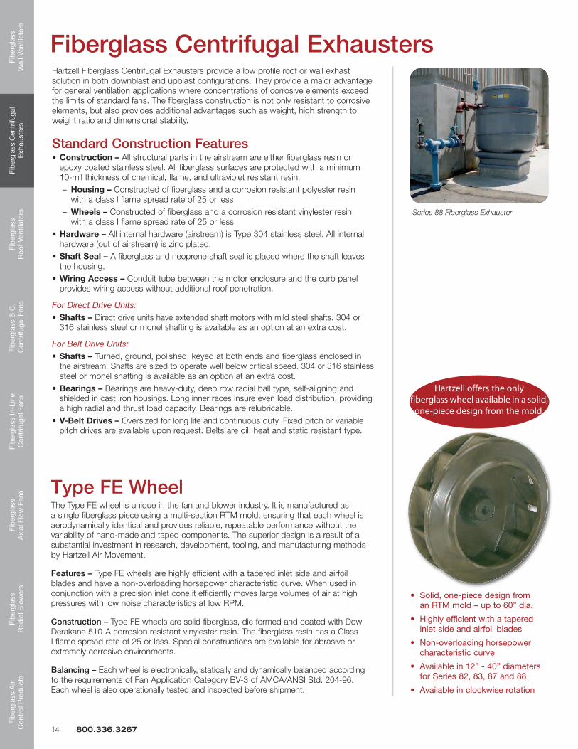
Hartzell Fiberglass Centrifugal Exhausters provide a low profile roof or wall exhast solution in both downblast and upblast configurations. They provide a major advantage for general ventilation applications where concentrations of corrosive elements exceed the limits of standard fans. The fiberglass construction is not only resistant to corrosive elements, but also provides additional advantages such as weight, high strength to weight ratio and dimensional stability.
Standard Construction Features•Construction – All structural parts in the airstream are either fiberglass resin or epoxy coated stainless steel. All fiberglass surfaces are protected with a minimum 10-mil thickness of chemical, flame, and ultraviolet resistant resin. – Housing – Constructed of fiberglass and a corrosion resistant polyester resin with a class l flame spread rate of 25 or less – Wheels – Constructed of fiberglass and a corrosion resistant vinylester resin with a class I flame spread rate of 25 or less•Hardware – All internal hardware (airstream) is Type 304 stainless steel. All internal hardware (out of airstream) is zinc plated.•Shaft Seal – A fiberglass and neoprene shaft seal is placed where the shaft leaves the housing.•Wiring Access – Conduit tube between the motor enclosure and the curb panel provides wiring access without additional roof penetration.
For Direct Drive Units: •Shafts – Direct drive units have extended shaft motors with mild steel shafts. 304 or 316 stainless steel or monel shafting is available as an option at an extra cost.
For Belt Drive Units: •Shafts – Turned, ground, polished, keyed at both ends and fiberglass enclosed in the airstream. Shafts are sized to operate well below critical speed. 304 or 316 stainless steel or monel shafting is available as an option at an extra cost.•Bearings – Bearings are heavy-duty, deep row radial ball type, self-aligning and shielded in cast iron housings. Long inner races insure even load distribution, providing a high radial and thrust load capacity. Bearings are relubricable.•V-Belt Drives – Oversized for long life and continuous duty. Fixed pitch or variable pitch drives are available upon request. Belts are oil, heat and static resistant type.
Fiberglass Centrifugal Exhausters
Type FE WheelThe Type FE wheel is unique in the fan and blower industry. It is manufactured as a single fiberglass piece using a multi-section RTM mold, ensuring that each wheel is aerodynamically identical and provides reliable, repeatable performance without the variability of hand-made and taped components. The superior design is a result of a substantial investment in research, development, tooling, and manufacturing methods by Hartzell Air Movement.
Features – Type FE wheels are highly efficient with a tapered inlet side and airfoil blades and have a non-overloading horsepower characteristic curve. When used in conjunction with a precision inlet cone it efficiently moves large volumes of air at high pressures with low noise characteristics at low RPM.
Construction – Type FE wheels are solid fiberglass, die formed and coated with Dow Derakane 510-A corrosion resistant vinylester resin. The fiberglass resin has a Class I flame spread rate of 25 or less. Special constructions are available for abrasive or extremely corrosive environments.
Balancing – Each wheel is electronically, statically and dynamically balanced according to the requirements of Fan Application Category BV-3 of AMCA/ANSI Std. 204-96. Each wheel is also operationally tested and inspected before shipment.
Hartzell offers the only fiberglass wheel available in a solid,
one-piece design from the mold.
14 800.336.3267
Series 88 Fiberglass Exhauster
Fiberglass
Wall Ventilators
Fiberglass Centrifugal
Exhausters
Fiberglass
Roof Ventilators
Fiberglass B
.C.
Centrifugal Fans
Fiberglass In-Line
Centrifugal Fans
Fiberglass
Axial Flow
FansFib
erglass R
adial B
lowers
Fiberglass A
ir C
ontrol Prod
ucts
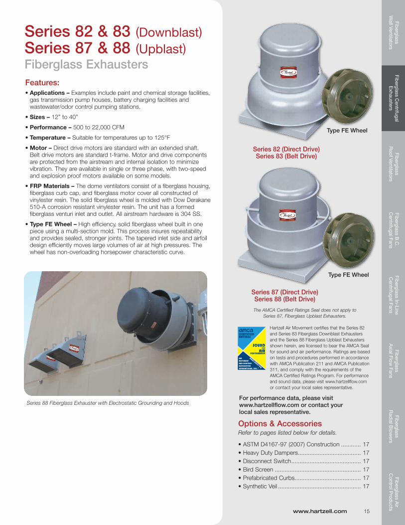
Series 82 & 83 (Downblast)Series 87 & 88 (Upblast)Fiberglass ExhaustersFeatures: •Applications – Examples include paint and chemical storage facilities, gas transmission pump houses, battery charging facilities and wastewater/odor control pumping stations.
•Sizes – 12” to 40”
•Performance – 500 to 22,000 CFM
•Temperature– Suitablefortemperaturesupto125°F
•Motor – Direct drive motors are standard with an extended shaft. Belt drive motors are standard t-frame. Motor and drive components are protected from the airstream and internal isolation to minimize vibration. They are available in single or three phase, with two-speed and explosion proof motors available on some models.
• FRP Materials – The dome ventilators consist of a fiberglass housing, fiberglass curb cap, and fiberglass motor cover all constructed of vinylester resin. The solid fiberglass wheel is molded with Dow Derakane 510-A corrosion resistant vinylester resin. The unit has a formed fiberglass venturi inlet and outlet. All airstream hardware is 304 SS.
•TypeFEWheel–High efficiency, solid fiberglass wheel built in one piece using a multi-section mold. This process insures repeatability and provides sealed, stronger joints. The tapered inlet side and airfoil design efficiently moves large volumes of air at high pressures. The wheel has non-overloading horsepower characteristic curve.
Options & AccessoriesRefer to pages listed below for details.
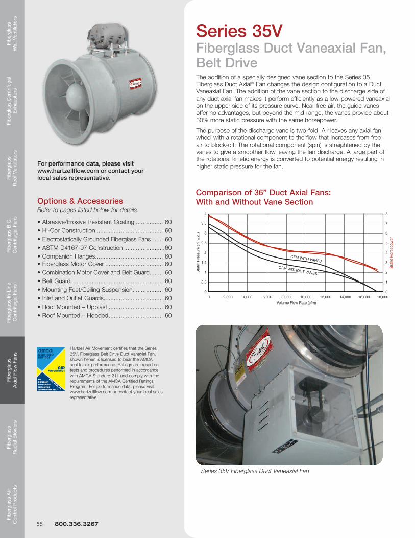
For performance data, please visit www.hartzellflow.com or contact your local sales representative.
Type FE Wheel
Series 82 (Direct Drive)Series 83 (Belt Drive)
Series 87 (Direct Drive) Series 88 (Belt Drive)
www.hartzell.com 15
Series 88 Fiberglass Exhauster with Electrostatic Grounding and Hoods
Hartzell Air Movement certifies that the Series 82 and Series 83 Fiberglass Downblast Exhausters and the Series 88 Fiberglass Upblast Exhausters shown herein, are licensed to bear the AMCA Seal for sound and air performance. Ratings are based on tests and procedures performed in accordance with AMCA Publication 211 and AMCA Publication 311, and comply with the requirements of the AMCA Certified Ratings Program. For performance and sound data, please visit www.hartzellflow.com or contact your local sales representative.
The AMCA Certified Ratings Seal does not apply to Series 87, Fiberglass Upblast Exhausters.
Fib
ergl
ass
Wal
l Ven
tilat
ors
Fibe
rgla
ss C
entr
ifuga
l E
xhau
ster
sFi
ber
glas
s R
oof V
entil
ator
sFi
ber
glas
s B
.C.
Cen
trifu
gal F
ans
Fib
ergl
ass
In-L
ine
Cen
trifu
gal F
ans
Fib
ergl
ass
Axi
al F
low
Fan
sFi
ber
glas
s R
adia
l Blo
wer
sFi
ber
glas
s A
ir C
ontr
ol P
rod
ucts
C
D
A
E
F
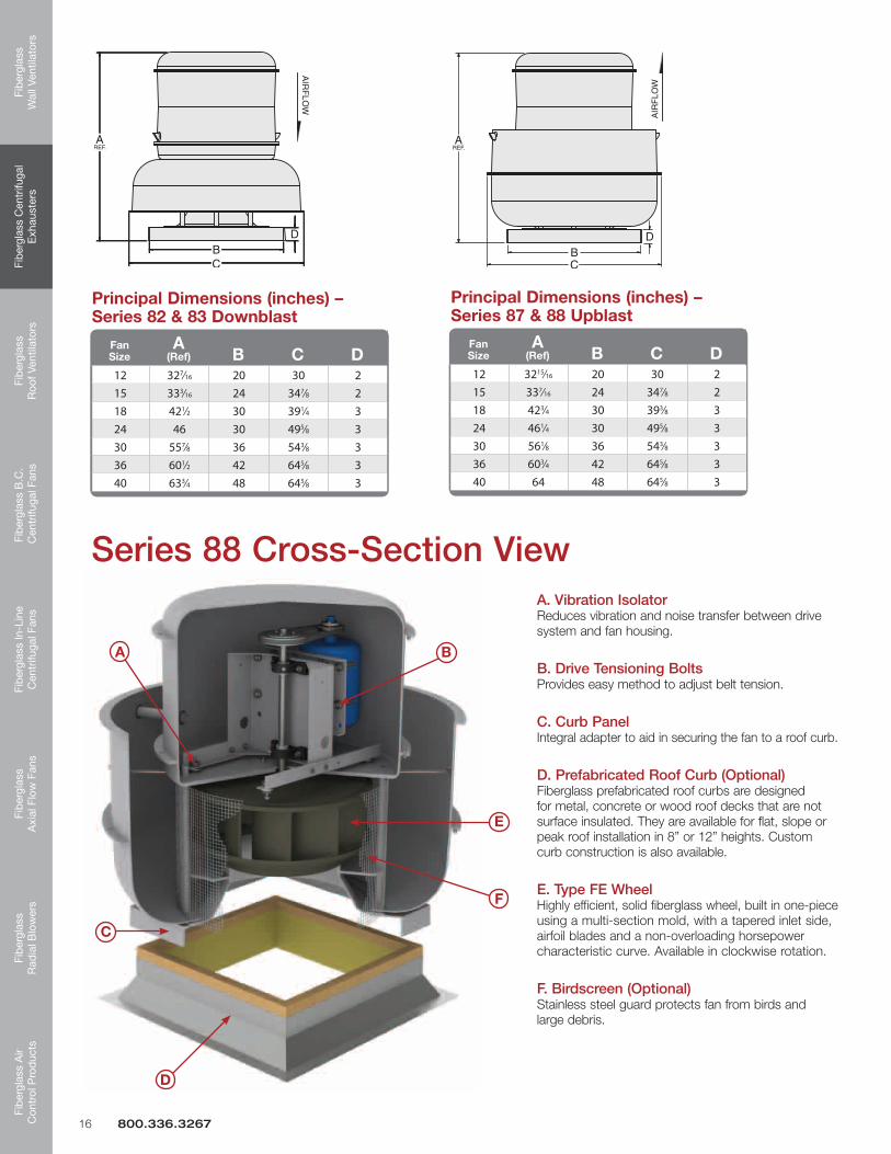
Series 88 Cross-Section ViewA. Vibration Isolator Reduces vibration and noise transfer between drive system and fan housing.
B. Drive Tensioning Bolts Provides easy method to adjust belt tension.
C. Curb Panel Integral adapter to aid in securing the fan to a roof curb.
D. Prefabricated Roof Curb (Optional) Fiberglass prefabricated roof curbs are designed for metal, concrete or wood roof decks that are not surface insulated. They are available for flat, slope or peak roof installation in 8” or 12” heights. Custom curb construction is also available.
E. Type FE Wheel Highly efficient, solid fiberglass wheel, built in one-piece using a multi-section mold, with a tapered inlet side, airfoil blades and a non-overloading horsepower characteristic curve. Available in clockwise rotation.
F. Birdscreen (Optional) Stainless steel guard protects fan from birds and large debris.
Principal Dimensions (inches) – Series87&88Upblast
16 800.336.3267
B
Fiberglass
Wall Ventilators
Fiberglass Centrifugal
Exhausters
Fiberglass
Roof Ventilators
Fiberglass B
.C.
Centrifugal Fans
Fiberglass In-Line
Centrifugal Fans
Fiberglass
Axial Flow
FansFib
erglass R
adial B
lowers
Fiberglass A
ir C
ontrol Prod
ucts
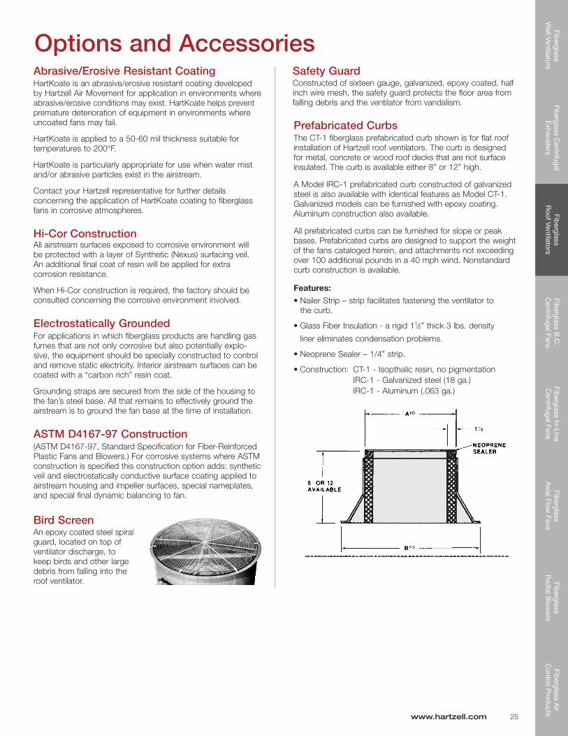
Prefabricated CurbsThe CT-1 fiberglass prefabricated curb shown is for flat roof installation of Hartzell centrifugal exhauster. The curb is designed for metal, concrete or wood roof decks that are not surface insulated. The curb is available either 8” or 12” high.
Model IRC-1 prefabricated curb constructed of galvanized steel is also available with identical features as Model CT-1. Galvanized models can be furnished with epoxy coating. Aluminum construction also available.
All prefabricated curbs can be furnished for slope or peak bases. Prefabricated curbs are designed to support the weight of the fans cataloged herein and attachments not exceeding over 100 additional pounds in a 40 mph wind. Nonstandard curb construction is available.
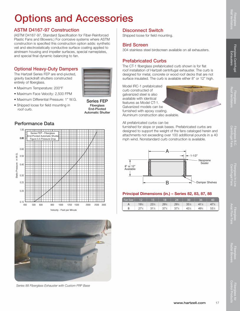
Performance Data
Disconnect SwitchShipped loose for field mounting.
Bird Screen304 stainless steel birdscreen available on all exhausters.
Optional Heavy-Duty DampersThe Hartzell Series FEP are end-pivoted, gravity backdraft shutters constructed entirely of fiberglass.
•MaximumTemperature:200°F
•MaximumFaceVelocity:2,500FPM
•MaximumDifferentialPressure:1”W.G.
•Shippedlooseforfieldmountingin roof curb.
Principal Dimensions (in.) – Series 82, 83, 87, 88Fan Size 12 15 18 24 30 36 40
Options and AccessoriesASTM D4167-97 Construction(ASTM D4167-97, Standard Specification for Fiber-Reinforced Plastic Fans and Blowers.) For corrosive systems where ASTM construction is specified this construction option adds: synthetic veil and electrostatically conductive surface coating applied to airstream housing and impeller surfaces, special nameplates, and special final dynamic balancing to fan.
Series 88 Fiberglass Exhauster with Custom FRP Base
Quality • Value • Commitment
SERIES 57
SERIES 37
SERIES 58E
Fiberglass Roof Ventilators
Fiberglass
Wall Ventilators
Fiberglass Centrifugal
Exhausters
Fiberglass
Roof Ventilators
Fiberglass B
.C.
Centrifugal Fans
Fiberglass In-Line
Centrifugal Fans
Fiberglass
Axial Flow
FansFib
erglass R
adial B
lowers
Fiberglass A
ir C
ontrol Prod
ucts
Hartzell Fiberglass Roof Ventilators are a practical choice for industrial applications where corrosive elements exist in fume and vapor form. They are designed and engineered to provide positive and accurate ventilation, regardless of internal plant and weather conditions.
The design utilizes a highly efficient fiberglass airfoil propeller in a heavy-duty, corrosive resistant fiberglass housing. The housing is extremely durable and highly resistant to impact.
In addition, the units offer weather-resistant characteristics because of their fiberglass construction. They will not tarnish and will never need painting.
Standard Construction Features•Housings–Constructed of a corrosion resistant vinylester resin with a class l flame spread rate of 25 or less
•FRPConstruction– All structural parts in the airstream are fiberglass and resin. All taped joints inside the shell or body are three layers of two ounce material. After assembly, internal surfaces are coated with two coats of resin and external parts and surfaces are given one coat of resin.
Fiberglass Roof Ventilators•UVInhibitor– A UV inhibitor is added to the final coat of resin.
•Shafts&Hardware– Airstream shafts, bolts, and screws are 304 SS. Monel shafting and hardware are available as an extra-cost option for applications such as hydrochloric, hydrofluoric, or sulfuric acids, which attach stainless. Where metal is subject to attack by the corrosive elements being handled, all metal parts can be resin-coated after assembly.
•Propellers– are of one-piece construction, die formed of individual laminations of cloth mat plus woven roving.
For Belt Drive Units:
•BearingCovers– Sealed with plastic foam tape and bolted to the bearing base.
•ShaftSeal– A fiberglass and neoprene shaft seal is placed where the shaft leaves the bearing cover along with a neoprene shaft slinger on the fan shaft between the propeller and seal. The seal is not gas tight.
Installation DataIn the past, the majority of plant ventilation was accomplished by sidewall ventilation. However, this type of ventilation required extensive and expensive ductwork and proved to be inferior to roof ventilation.
Roof ventilators use little valuable internal space and offer the flexibility of rearranging production equipment without recon-structing ventilation systems and moving ductwork.
Hartzell offers three types of fiberglass roof ventilators, each designed with a particular type of installation in mind, to meet the majority of industrial corrosive applications.
Series57: FiberglassUpblastRoofVentilator–DirectDrive An efficient and economical choice for general ventilation or mildly corrosive atmospheres.
Series37: FiberglassUpblastRoofVentilator–BeltDrive A heavy-duty unit with the motor out of the airstream, best suited for application where severely corrosive elements exist or where the versatility of belt drive is required. Can be located at the end of ductwork.
Series 58: Fiberglass Hooded Roof Ventilator – Belt Drive Provides complete protection from the elements for an exhaust operation.
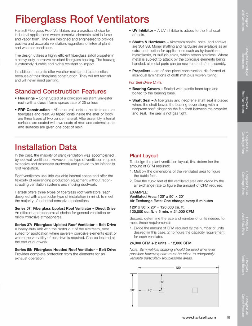
Plant LayoutTo design the plant ventilation layout, first determine the amount of CFM required: 1. Multiply the dimensions of the ventilated area to figure the cubic feet.2. Take the cubic feet of the ventilated area and divide by the air exchange rate to figure the amount of CFM required.
EXAMPLE: Ventilated Area: 120’ x 50’ x 20’ Air Exchange Rate: One change every 5 minutes
120’ x 50’ x 20’ = 120,000 cu. ft. 120,000 cu. ft. ÷ 5 min. = 24,000 CFM
Second, determine the size and number of units needed to meet those requirements:1. Divide the amount of CFM required by the number of units desired (in this case, 2) to figure the capacity requirement for each ventilator.
24,000 CFM ÷ 2 units = 12,000 CFM
Note: Symmetrical spacing should be used whenever possible; however, care must be taken to adequately ventilate particularly troublesome areas.
www.hartzell.com 19
Fib
ergl
ass
Wal
l Ven
tilat
ors
Fibe
rgla
ss C
entr
ifuga
l E
xhau
ster
sFi
ber
glas
s R
oof V
entil
ator
sFi
ber
glas
s B
.C.
Cen
trifu
gal F
ans
Fib
ergl
ass
In-L
ine
Cen
trifu
gal F
ans
Fib
ergl
ass
Axi
al F
low
Fan
sFi
ber
glas
s R
adia
l Blo
wer
sFi
ber
glas
s A
ir C
ontr
ol P
rod
ucts
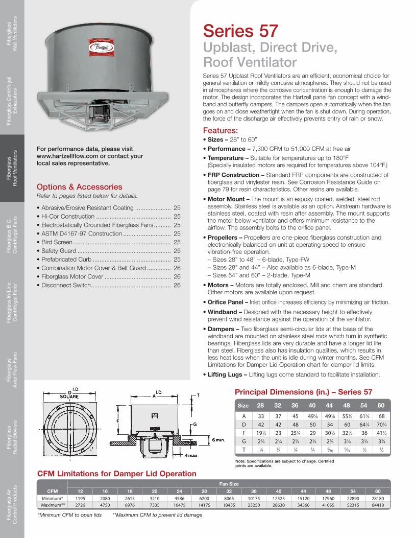
Series 57 Upblast Roof Ventilators are an efficient, economical choice for general ventilation or mildly corrosive atmospheres. They should not be used in atmospheres where the corrosive concentration is enough to damage the motor. The design incorporates the Hartzell panel fan concept with a wind- band and butterfly dampers. The dampers open automatically when the fan goes on and close weathertight when the fan is shut down. During operation, the force of the discharge air effectively prevents entry of rain or snow.
Features:•Sizes – 28” to 60”
•Performance – 7,300 CFM to 51,000 CFM at free air
•FRP Construction – Standard FRP components are constructed of fiberglass and vinylester resin. See Corrosion Resistance Guide on page 79 for resin characteristics. Other resins are available.
•Motor Mount – The mount is an expoxy coated, welded, steel rod assembly. Stainless steel is available as an option. Airstream hardware is stainless steel, coated with resin after assembly. The mount supports the motor below ventilator and offers minimum resistance to the airflow. The assembly bolts to the orifice panel.
•Propellers – Propellers are one-piece fiberglass construction and electronically balanced on unit at operating speed to ensure vibration-free operation. – Sizes 28” to 48” – 6-blade, Type-FW – Sizes 28” and 44” – Also available as 6-blade, Type-M – Sizes 54” and 60” – 2-blade, Type-M
•Motors – Motors are totally enclosed. Mill and chem are standard. Other motors are available upon request.
•Orifice Panel – Inlet orifice increases efficiency by minimizing air friction.
•Windband – Designed with the necessary height to effectively prevent wind resistance against the operation of the ventilator.
• Dampers – Two fiberglass semi-circular lids at the base of the windband are mounted on stainless steel rods which turn in synthetic bearings. Fiberglass lids are very durable and have a longer lid life than steel. Fiberglass also has insulation qualities, which results in less heat loss when the unit is idle during winter months. See CFM Limitations for Damper Lid Operation chart for damper lid limits.
• Lifting Lugs – Lifting lugs come standard to facilitate installation.
Series 57Upblast, Direct Drive, Roof Ventilator
CFM Limitations for Damper Lid Operation
*Minimum CFM to open lids **Maximum CFM to prevent lid damage
Note: Specifications are subject to change. Certified prints are available.
For performance data, please visit www.hartzellflow.com or contact your local sales representative.
Fiberglass
Wall Ventilators
Fiberglass Centrifugal
Exhausters
Fiberglass
Roof Ventilators
Fiberglass B
.C.
Centrifugal Fans
Fiberglass In-Line
Centrifugal Fans
Fiberglass
Axial Flow
FansFib
erglass R
adial B
lowers
Fiberglass A
ir C
ontrol Prod
ucts
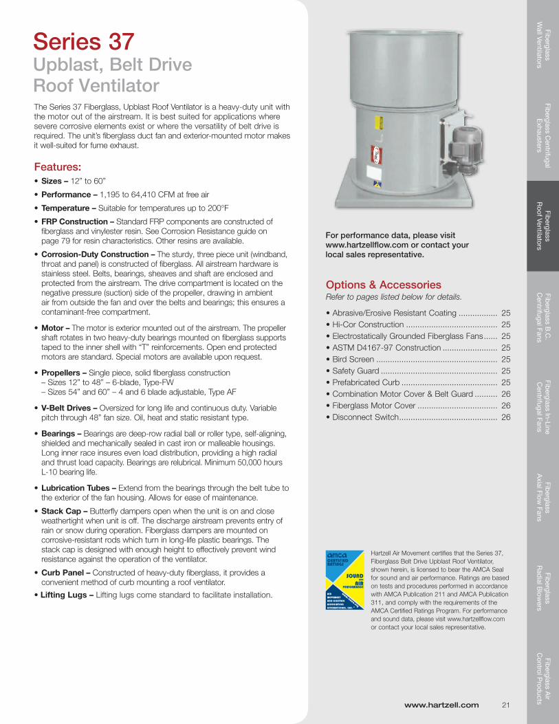
Series 37Upblast, Belt Drive Roof VentilatorThe Series 37 Fiberglass, Upblast Roof Ventilator is a heavy-duty unit with the motor out of the airstream. It is best suited for applications where severe corrosive elements exist or where the versatility of belt drive is required. The unit’s fiberglass duct fan and exterior-mounted motor makes it well-suited for fume exhaust.
Features:•Sizes – 12” to 60”
•Performance – 1,195 to 64,410 CFM at free air
•Temperature–Suitablefortemperaturesupto200°F
•FRP Construction – Standard FRP components are constructed of fiberglass and vinylester resin. See Corrosion Resistance guide on page 79 for resin characteristics. Other resins are available.
•Corrosion-DutyConstruction– The sturdy, three piece unit (windband, throat and panel) is constructed of fiberglass. All airstream hardware is stainless steel. Belts, bearings, sheaves and shaft are enclosed and protected from the airstream. The drive compartment is located on the negative pressure (suction) side of the propeller, drawing in ambient air from outside the fan and over the belts and bearings; this ensures a contaminant-free compartment.
•Motor – The motor is exterior mounted out of the airstream. The propeller shaft rotates in two heavy-duty bearings mounted on fiberglass supports taped to the inner shell with “T” reinforcements. Open end protected motors are standard. Special motors are available upon request.
•Propellers – Single piece, solid fiberglass construction – Sizes 12” to 48” – 6-blade, Type-FW – Sizes 54” and 60” – 4 and 6 blade adjustable, Type AF
•V-Belt Drives – Oversized for long life and continuous duty. Variable pitch through 48” fan size. Oil, heat and static resistant type.
•Bearings – Bearings are deep-row radial ball or roller type, self-aligning, shielded and mechanically sealed in cast iron or malleable housings. Long inner race insures even load distribution, providing a high radial and thrust load capacity. Bearings are relubrical. Minimum 50,000 hours L-10 bearing life.
•LubricationTubes– Extend from the bearings through the belt tube to the exterior of the fan housing. Allows for ease of maintenance.
•Stack Cap – Butterfly dampers open when the unit is on and close weathertight when unit is off. The discharge airstream prevents entry of rain or snow during operation. Fiberglass dampers are mounted on corrosive-resistant rods which turn in long-life plastic bearings. The stack cap is designed with enough height to effectively prevent wind resistance against the operation of the ventilator.
•Curb Panel – Constructed of heavy-duty fiberglass, it provides a convenient method of curb mounting a roof ventilator.
• Lifting Lugs – Lifting lugs come standard to facilitate installation.
Hartzell Air Movement certifies that the Series 37, Fiberglass Belt Drive Upblast Roof Ventilator, shown herein, is licensed to bear the AMCA Seal for sound and air performance. Ratings are based on tests and procedures performed in accordance with AMCA Publication 211 and AMCA Publication 311, and comply with the requirements of the AMCA Certified Ratings Program. For performance and sound data, please visit www.hartzellflow.com or contact your local sales representative.
Options & AccessoriesRefer to pages listed below for details.
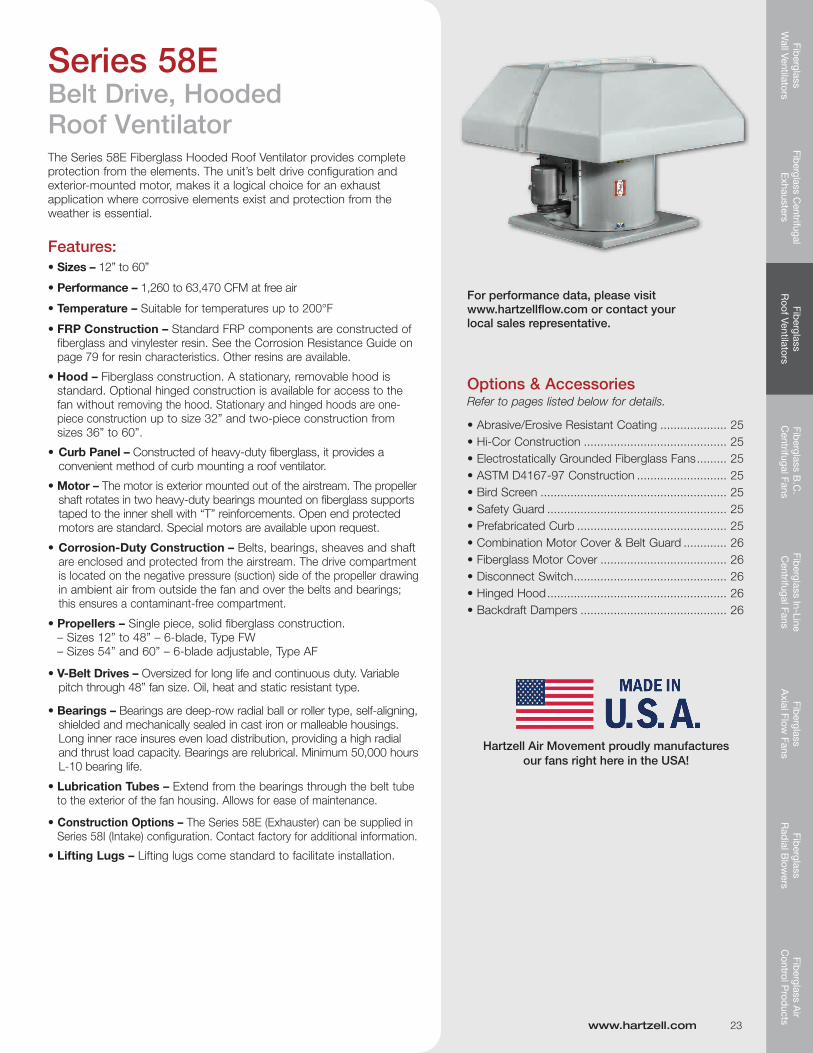
Series 58EBelt Drive, Hooded Roof VentilatorThe Series 58E Fiberglass Hooded Roof Ventilator provides complete protection from the elements. The unit’s belt drive configuration and exterior-mounted motor, makes it a logical choice for an exhaust application where corrosive elements exist and protection from the weather is essential.
Features:•Sizes – 12” to 60”
•Performance – 1,260 to 63,470 CFM at free air
•Temperature–Suitablefortemperaturesupto200°F
•FRP Construction – Standard FRP components are constructed of fiberglass and vinylester resin. See the Corrosion Resistance Guide on page 79 for resin characteristics. Other resins are available.
•Hood – Fiberglass construction. A stationary, removable hood is standard. Optional hinged construction is available for access to the fan without removing the hood. Stationary and hinged hoods are one- piece construction up to size 32” and two-piece construction from sizes 36” to 60”.
•Curb Panel – Constructed of heavy-duty fiberglass, it provides a convenient method of curb mounting a roof ventilator.
•Motor – The motor is exterior mounted out of the airstream. The propeller shaft rotates in two heavy-duty bearings mounted on fiberglass supports taped to the inner shell with “T” reinforcements. Open end protected motors are standard. Special motors are available upon request.
•Corrosion-DutyConstruction– Belts, bearings, sheaves and shaft are enclosed and protected from the airstream. The drive compartment is located on the negative pressure (suction) side of the propeller drawing in ambient air from outside the fan and over the belts and bearings; this ensures a contaminant-free compartment.
•Propellers – Single piece, solid fiberglass construction. – Sizes 12” to 48” – 6-blade, Type FW – Sizes 54” and 60” – 6-blade adjustable, Type AF
•V-Belt Drives – Oversized for long life and continuous duty. Variable pitch through 48” fan size. Oil, heat and static resistant type.
•Bearings – Bearings are deep-row radial ball or roller type, self-aligning, shielded and mechanically sealed in cast iron or malleable housings. Long inner race insures even load distribution, providing a high radial and thrust load capacity. Bearings are relubrical. Minimum 50,000 hours L-10 bearing life.
•LubricationTubes– Extend from the bearings through the belt tube to the exterior of the fan housing. Allows for ease of maintenance.
•Construction Options – The Series 58E (Exhauster) can be supplied in Series 58I (Intake) configuration. Contact factory for additional information.
• Lifting Lugs – Lifting lugs come standard to facilitate installation.
Options & AccessoriesRefer to pages listed below for details.
Prefabricated CurbsThe CT-1 fiberglass prefabricated curb shown is for flat roof installation of Hartzell roof ventilators. The curb is designed for metal, concrete or wood roof decks that are not surface insulated. The curb is available either 8” or 12” high.
A Model IRC-1 prefabricated curb constructed of galvanized steel is also available with identical features as Model CT-1. Galvanized models can be furnished with epoxy coating. Aluminum construction also available.
All prefabricated curbs can be furnished for slope or peak bases. Prefabricated curbs are designed to support the weight of the fans cataloged herein, and attachments not exceeding over 100 additional pounds in a 40 mph wind. Nonstandard curb construction is available.
Features:
•NailerStrip–stripfacilitatesfasteningthe ventilator to the curb.
•GlassFiberInsulation-arigid11⁄2” thick 3 lbs. density
Bird ScreenAn epoxy coated steel spiral guard, located on top of ventilator discharge, to keep birds and other large debris from falling into the roof ventilator.
www.hartzell.com 25
Abrasive/Erosive Resistant CoatingHartKoate is an abrasive/erosive resistant coating developed by Hartzell Air Movement for application in environments where abrasive/erosive conditions may exist. HartKoate helps prevent premature deterioration of equipment in environments where uncoated fans may fail.
HartKoate is applied to a 50-60 mil thickness suitable for temperaturesto200°F.
HartKoate is particularly appropriate for use when water mist and/or abrasive particles exist in the airstream.
Contact your Hartzell representative for further details concerning the application of HartKoate coating to fiberglass fans in corrosive atmospheres.
Hi-Cor ConstructionAll airstream surfaces exposed to corrosive environment will be protected with a layer of Synthetic (Nexus) surfacing veil. An additional final coat of resin will be applied for extra corrosion resistance.
When Hi-Cor construction is required, the factory should be consulted concerning the corrosive environment involved.
Electrostatically GroundedFor applications in which fiberglass products are handling gas fumes that are not only corrosive but also potentially explo-sive, the equipment should be specially constructed to control and remove static electricity. Interior airstream surfaces can be coated with a “carbon rich” resin coat.
Grounding straps are secured from the side of the housing to the fan’s steel base. All that remains to effectively ground the airstream is to ground the fan base at the time of installation.
ASTM D4167-97 Construction(ASTM D4167-97, Standard Specification for Fiber-Reinforced Plastic Fans and Blowers.) For corrosive systems where ASTM construction is specified this construction option adds: synthetic veil and electrostatically conductive surface coating applied to airstream housing and impeller surfaces, special nameplates, and special final dynamic balancing to fan.
Safety GuardConstructed of sixteen gauge, galvanized, epoxy coated, half inch wire mesh, the safety guard protects the floor area from falling debris and the ventilator from vandalism.
Fib
ergl
ass
Wal
l Ven
tilat
ors
Fibe
rgla
ss C
entr
ifuga
l E
xhau
ster
sFi
ber
glas
s R
oof V
entil
ator
sFi
ber
glas
s B
.C.
Cen
trifu
gal F
ans
Fib
ergl
ass
In-L
ine
Cen
trifu
gal F
ans
Fib
ergl
ass
Axi
al F
low
Fan
sFi
ber
glas
s R
adia
l Blo
wer
sFi
ber
glas
s A
ir C
ontr
ol P
rod
ucts
Options and Accessories
26 800.336.3267
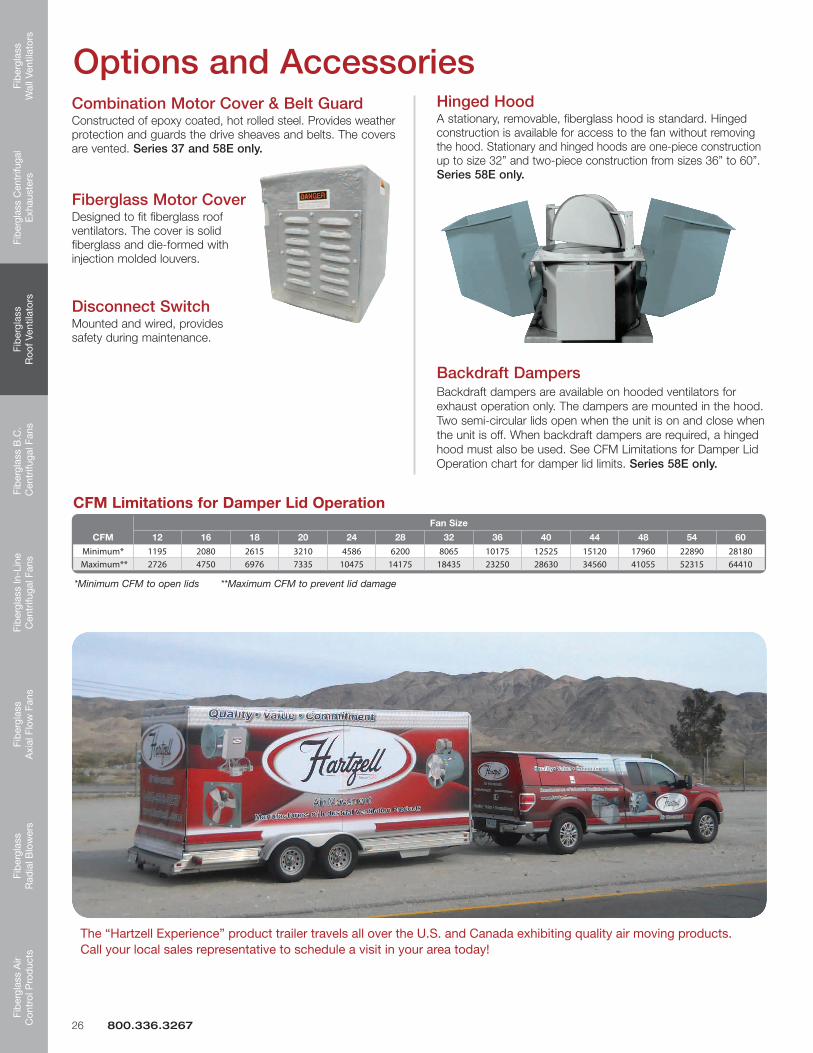
Hinged HoodA stationary, removable, fiberglass hood is standard. Hinged construction is available for access to the fan without removing the hood. Stationary and hinged hoods are one-piece construction up to size 32” and two-piece construction from sizes 36” to 60”. Series 58E only.
Backdraft DampersBackdraft dampers are available on hooded ventilators for exhaust operation only. The dampers are mounted in the hood. Two semi-circular lids open when the unit is on and close when the unit is off. When backdraft dampers are required, a hinged hood must also be used. See CFM Limitations for Damper Lid Operation chart for damper lid limits. Series 58E only.
CFM Limitations for Damper Lid Operation
*Minimum CFM to open lids **Maximum CFM to prevent lid damage
Combination Motor Cover & Belt GuardConstructed of epoxy coated, hot rolled steel. Provides weather protection and guards the drive sheaves and belts. The covers are vented. Series 37 and 58E only.
Fiberglass Motor CoverDesigned to fit fiberglass roof ventilators. The cover is solid fiberglass and die-formed with injection molded louvers.
Disconnect SwitchMounted and wired, provides safety during maintenance.
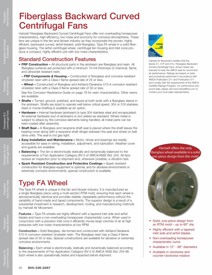
Hartzell Fiberglass Backward Curved Centrifugal Fans offer non-overloading horsepower characteristics, high efficiency, low noise and economy for corrosive atmospheres. These fans are unique in the fan and blower industry as they incorporate the proven, highly efficient, backward curved, airfoil-bladed, solid fiberglass, Type FA wheel in a solid fiber-glass housing. The airfoil centrifugal wheel, centrifugal fan housing and inlet cone pro-duce a compact, highly efficient unit with low noise characteristics.
Standard Construction Features•FRP Construction – All structural parts in the airstream are fiberglass and resin. All fiberglass surfaces are protected with a minimum 10-mil thickness of chemical, flame, and ultraviolet resistant resin. – FRP Components & Housing – Constructed of fiberglass and corrosive resistant vinylester resin with a Class I flame spread rate of 25 or less. – Wheel – Constructed of fiberglass and Ashland Derakane 510-A corrosion resistant vinylester resin with a Class Il flame spread rate of 30 or less. See the Corrosion Resistance Guide on page 79 for resin characteristics. Other resins are available.•Shafts – Turned, ground, polished, and keyed at both ends with a fiberglass sleeve in the airstream. Shafts are sized to operate well below critical speed. 304 or 316 stainless steel or monel shafting is available as an option. •Hardware – Internal hardware (airstream) is type 304 stainless steel and encapsulated. All external hardware (out of airstream) is zinc plated as standard. Where metal is subject to attack by the corrosive elements being handled, all metal parts can be resin-coated after assembly. •Shaft Seal – A fiberglass and neoprene shaft seal is placed where the shaft leaves the bearing cover along with a neoprene shaft slinger between the seal and wheel on belt drive units. The seal is not gas tight.
• EasyInstallationandMaintenance– Motor, drives and bearings are readily accessible for ease in wiring, installation, adjustment, and lubrication. Weather cover and guards are available.
• Balancing – The fan is electronically statically and dynamically balanced to the requirements of Fan Application Category BV-3 of AMCA/ANSI Std. 204. All fans receive an inspection prior to shipment and, whenever possible, a vibration test.
• Spark Resistant Construction and Protective Coatings – Spark resistant construction for fiberglass equipment is optional, and for abrasive environments or extremely corrosive environments, special construction is available.
Fiberglass Backward Curved Centrifugal Fans
Hartzell Air Movement certifies that the Series 41, 41P and 41U, Fiberglass Backward Curved Centrifugal Fans, shown herein are licensed to bear the AMCA seal for sound and air performance. Ratings are based on tests and procedures performed in accordance with AMCA Publication 211 and Publication 311 and comply with the requirements of the AMCA Certified Ratings Program. For performance and sound data, please visit www.hartzellflow.com or contact your local sales representative.
Type FA WheelThe Type FA wheel is unique in the fan and blower industry. It is manufactured as a single fiberglass piece using a multi-section RTM mold, ensuring that each wheel is aerodynamically identical and provides reliable, repeatable performance without the variability of hand-made and taped components. The superior design is a result of a substantial investment in research, development, tooling, and manufacturing methods by Hartzell Air Movement.
Features – Type FA wheels are highly efficient with a tapered inlet side and airfoil blades and have a non-overloading horsepower characteristic curve. When used in conjunction with a precision inlet cone it efficiently moves large volumes of air at high pressures with low noise characteristics at low RPM.
Construction – Solid fiberglass, die formed and constructed with Ashland Derakane 510-A corrosion resistant vinylester resin. The fiberglass resin has a Class II flame spread rate of 30 or less. Special constructions are available for abrasive or extremely corrosive environments.
Balancing – Each wheel is electronically, statically and dynamically balanced according to the requirements of Fan Application Category BV-3 of AMCA ANSI Std. 204-96. Each wheel is also operationally tested and inspected before shipment.
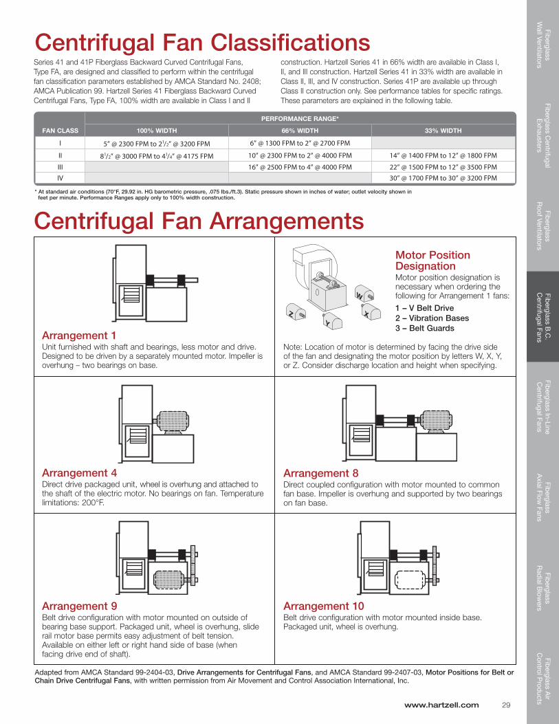
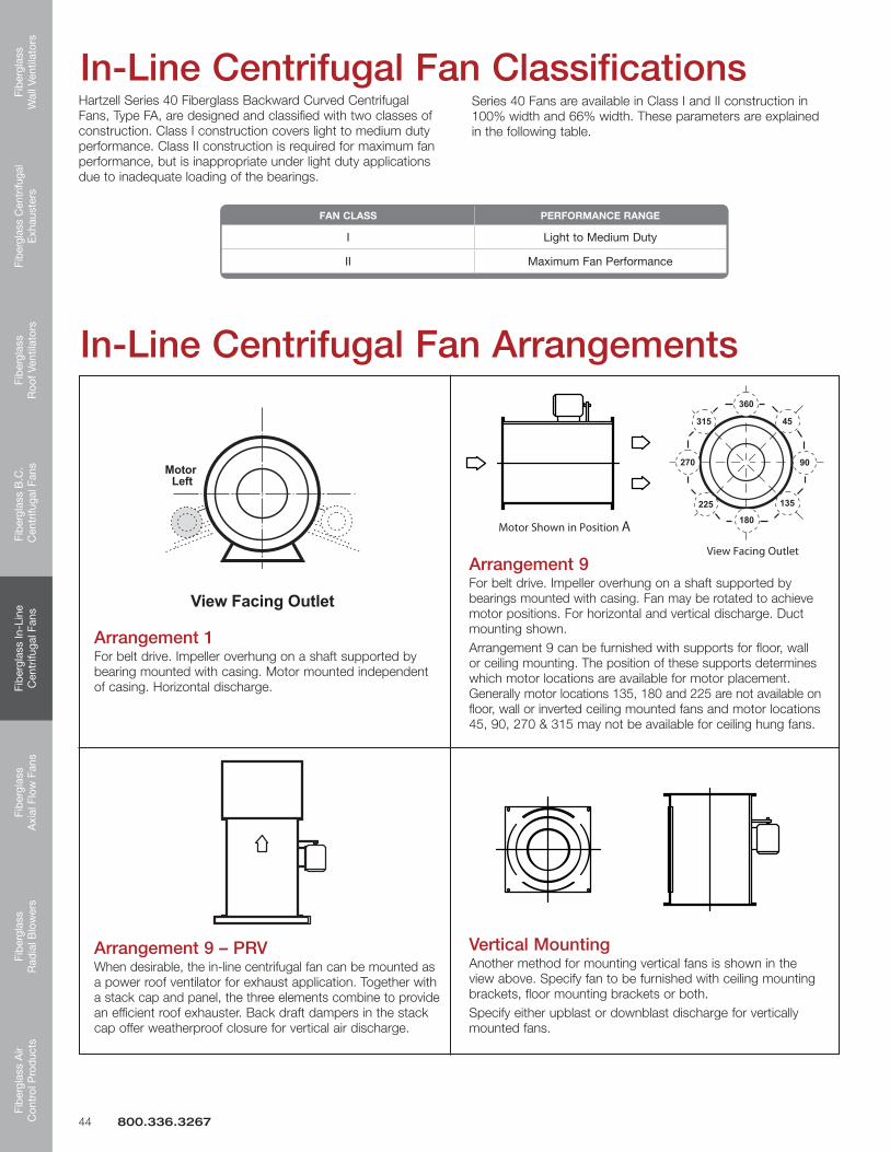
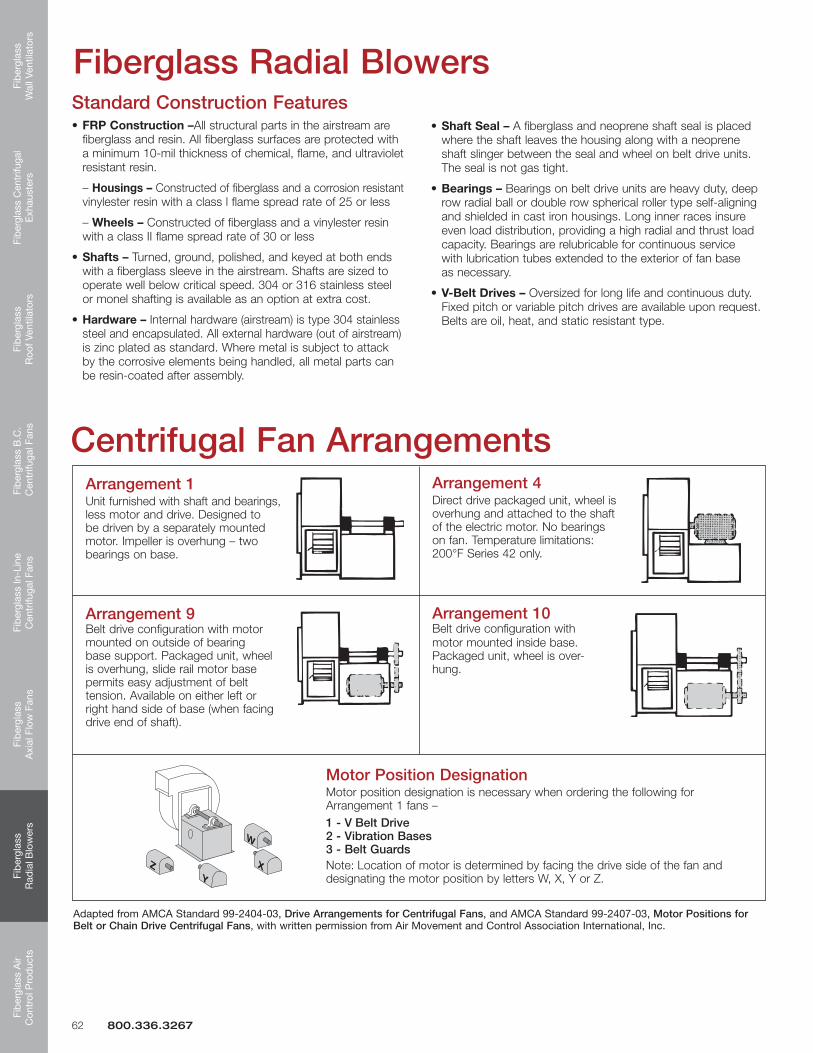
Arrangement 1 Unit furnished with shaft and bearings, less motor and drive. Designed to be driven by a separately mounted motor. Impeller is overhung – two bearings on base.
Arrangement 9 Belt drive configuration with motor mounted on outside of bearing base support. Packaged unit, wheel is overhung, slide rail motor base permits easy adjustment of belt tension. Available on either left or right hand side of base (when facing drive end of shaft).
Arrangement 10 Belt drive configuration with motor mounted inside base. Packaged unit, wheel is overhung.
Arrangement 4 Direct drive packaged unit, wheel is overhung and attached to the shaft of the electric motor. No bearings on fan. Temperature limitations:200°F.
Motor Position Designation Motor position designation is necessary when ordering the following for Arrangement 1 fans:
1 – V Belt Drive 2 – Vibration Bases 3 – Belt Guards
Note: Location of motor is determined by facing the drive side of the fan and designating the motor position by letters W, X, Y, or Z. Consider discharge location and height when specifying.
Arrangement 8 Direct coupled configuration with motor mounted to common fan base. Impeller is overhung and supported by two bearings on fan base.
AdaptedfromAMCAStandard99-2404-03,Drive Arrangements for Centrifugal Fans,andAMCAStandard99-2407-03,Motor Positions for Belt or Chain Drive Centrifugal Fans,withwrittenpermissionfromAirMovementandControlAssociationInternational,Inc.
Centrifugal Fan Classifications
* At standard air conditions (70°F, 29.92 in. HG barometric pressure, .075 lbs./ft.3). Static pressure shown in inches of water; outlet velocity shown in feet per minute. Performance Ranges apply only to 100% width construction.
Series 41 and 41P Fiberglass Backward Curved Centrifugal Fans, Type FA, are designed and classified to perform within the centrifugal fan classification parameters established by AMCA Standard No. 2408; AMCA Publication 99. Hartzell Series 41 Fiberglass Backward Curved CentrifugalFans,TypeFA,100%widthareavailableinClassIandII
construction.HartzellSeries41in66%widthareavailableinClassI,II,andIIIconstruction.HartzellSeries41in33%widthareavailableinClass II, III, and IV construction. Series 41P are available up through Class II construction only. See performance tables for specific ratings. These parameters are explained in the following table.
PERFORMANCERANGE*
FANCLASS 100%WIDTH 66%WIDTH 33%WIDTH
I 5” @ 2300 FPM to 21/2” @ 3200 FPM 6” @ 1300 FPM to 2” @ 2700 FPM
II 81/2” @ 3000 FPM to 41/4” @ 4175 FPM 10” @ 2300 FPM to 2” @ 4000 FPM 14” @ 1400 FPM to 12” @ 1800 FPM
III 16” @ 2500 FPM to 4” @ 4000 FPM 22” @ 1500 FPM to 12” @ 3500 FPMIV 30” @ 1700 FPM to 30” @ 3200 FPM
Fib
ergl
ass
Wal
l Ven
tilat
ors
Fibe
rgla
ss C
entr
ifuga
l E
xhau
ster
sFi
ber
glas
s R
oof V
entil
ator
sFi
ber
glas
s B
.C.
Cen
trifu
gal F
ans
Fib
ergl
ass
In-L
ine
Cen
trifu
gal F
ans
Fib
ergl
ass
Axi
al F
low
Fan
sFi
ber
glas
s R
adia
l Blo
wer
sFi
ber
glas
s A
ir C
ontr
ol P
rod
ucts
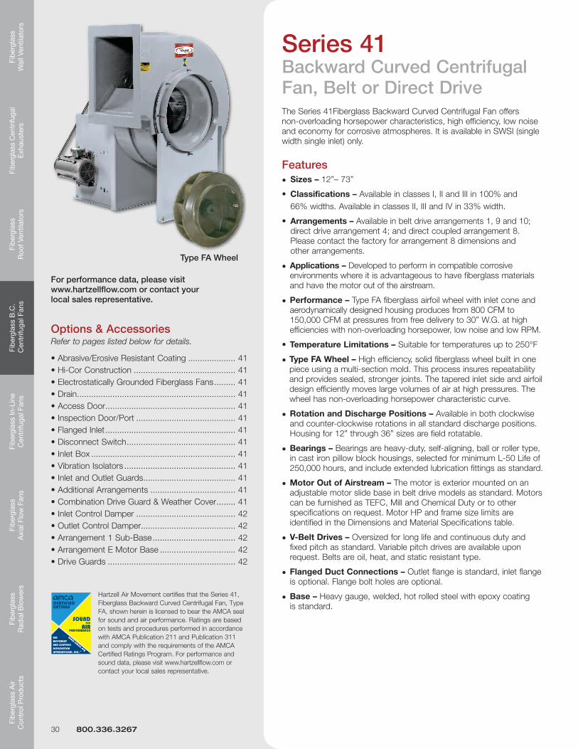
Series 41Backward Curved Centrifugal Fan, Belt or Direct DriveThe Series 41Fiberglass Backward Curved Centrifugal Fan offers non-overloading horsepower characteristics, high efficiency, low noise and economy for corrosive atmospheres. It is available in SWSI (single width single inlet) only.
• Arrangements – Available in belt drive arrangements 1, 9 and 10; direct drive arrangement 4; and direct coupled arrangement 8. Please contact the factory for arrangement 8 dimensions and other arrangements.
• Applications – Developed to perform in compatible corrosive environments where it is advantageous to have fiberglass materials and have the motor out of the airstream.
• Performance – Type FA fiberglass airfoil wheel with inlet cone and aerodynamically designed housing produces from 800 CFM to 150,000 CFM at pressures from free delivery to 30” W.G. at high efficiencies with non-overloading horsepower, low noise and low RPM.
• TypeFAWheel– High efficiency, solid fiberglass wheel built in one piece using a multi-section mold. This process insures repeatability and provides sealed, stronger joints. The tapered inlet side and airfoil design efficiently moves large volumes of air at high pressures. The wheel has non-overloading horsepower characteristic curve.
• Rotation and Discharge Positions – Available in both clockwise and counter-clockwise rotations in all standard discharge positions. Housing for 12” through 36” sizes are field rotatable.
• Bearings – Bearings are heavy-duty, self-aligning, ball or roller type, in cast iron pillow block housings, selected for minimum L-50 Life of 250,000 hours, and include extended lubrication fittings as standard.
• Motor Out of Airstream – The motor is exterior mounted on an adjustable motor slide base in belt drive models as standard. Motors can be furnished as TEFC, Mill and Chemical Duty or to other specifications on request. Motor HP and frame size limits are identified in the Dimensions and Material Specifications table.
• V-Belt Drives – Oversized for long life and continuous duty and fixed pitch as standard. Variable pitch drives are available upon request. Belts are oil, heat, and static resistant type.
• Flanged Duct Connections – Outlet flange is standard, inlet flange is optional. Flange bolt holes are optional.
• Base – Heavy gauge, welded, hot rolled steel with epoxy coating is standard.
Hartzell Air Movement certifies that the Series 41, Fiberglass Backward Curved Centrifugal Fan, Type FA, shown herein is licensed to bear the AMCA seal for sound and air performance. Ratings are based on tests and procedures performed in accordance with AMCA Publication 211 and Publication 311 and comply with the requirements of the AMCA Certified Ratings Program. For performance and sound data, please visit www.hartzellflow.com or contact your local sales representative.
Options & AccessoriesRefer to pages listed below for details.
For performance data, please visit www.hartzellflow.com or contact your local sales representative.
30 800.336.3267
Fiberglass
Wall Ventilators
Fiberglass Centrifugal
Exhausters
Fiberglass
Roof Ventilators
Fiberglass B
.C.
Centrifugal Fans
Fiberglass In-Line
Centrifugal Fans
Fiberglass
Axial Flow
FansFib
erglass R
adial B
lowers
Fiberglass A
ir C
ontrol Prod
ucts
www.hartzell.com 31
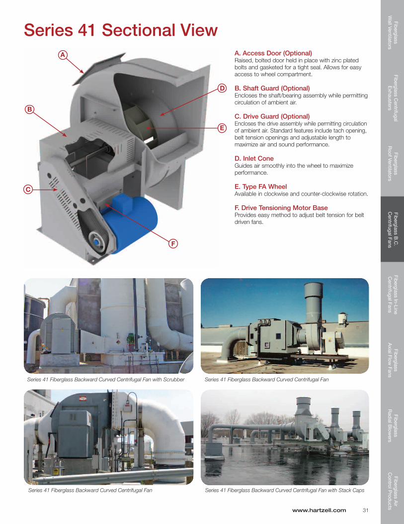
Series 41 Sectional ViewA. Access Door (Optional) Raised, bolted door held in place with zinc plated bolts and gasketed for a tight seal. Allows for easy access to wheel compartment.
B. Shaft Guard (Optional) Encloses the shaft/bearing assembly while permitting circulation of ambient air.
C. Drive Guard (Optional) Encloses the drive assembly while permitting circulation of ambient air. Standard features include tach opening, belt tension openings and adjustable length to maximize air and sound performance.
D. Inlet Cone Guides air smoothly into the wheel to maximize performance.
E. Type FA Wheel Available in clockwise and counter-clockwise rotation.
F. Drive Tensioning Motor Base Provides easy method to adjust belt tension for belt driven fans.
A
B
C
F
E
D
Series 41 Fiberglass Backward Curved Centrifugal Fan with Scrubber
Series 41 Fiberglass Backward Curved Centrifugal Fan
Series 41 Fiberglass Backward Curved Centrifugal Fan
Series 41 Fiberglass Backward Curved Centrifugal Fan with Stack Caps
Fib
ergl
ass
Wal
l Ven
tilat
ors
Fibe
rgla
ss C
entr
ifuga
l E
xhau
ster
sFi
ber
glas
s R
oof V
entil
ator
sFi
ber
glas
s B
.C.
Cen
trifu
gal F
ans
Fib
ergl
ass
In-L
ine
Cen
trifu
gal F
ans
Fib
ergl
ass
Axi
al F
low
Fan
sFi
ber
glas
s R
adia
l Blo
wer
sFi
ber
glas
s A
ir C
ontr
ol P
rod
ucts
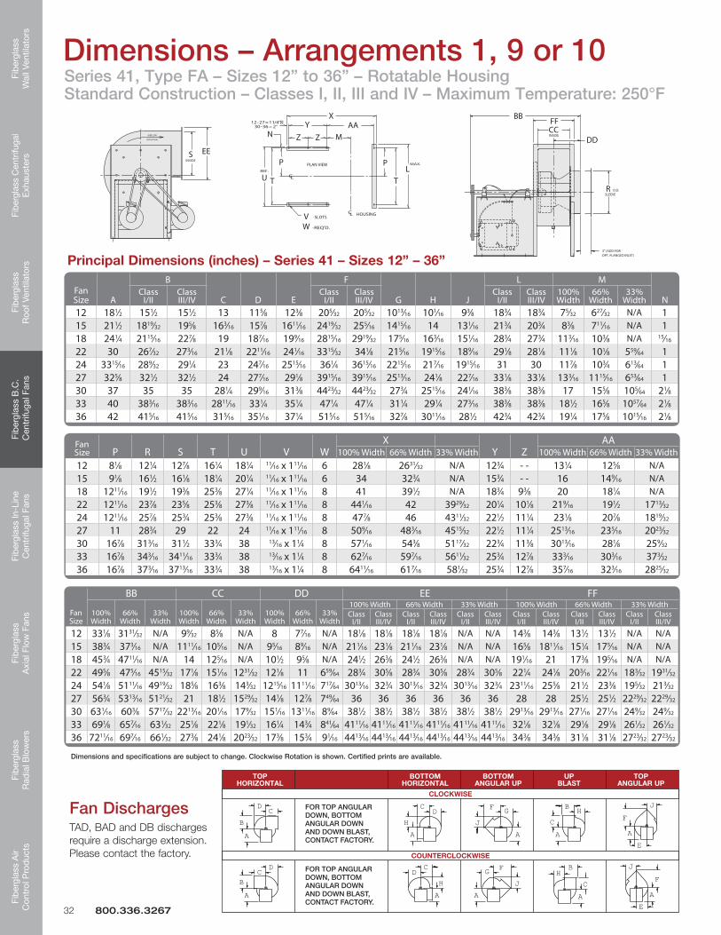
Series 41, Type FA – Sizes 12” to 36” – Rotatable Housing Standard Construction – Classes I, II, III and IV – Maximum Temperature: 250°F
Principal Dimensions (inches) – Series 41 – Sizes 12” – 36”
Dimensions and specifications are subject to change. Clockwise Rotation is shown. Certified prints are available.
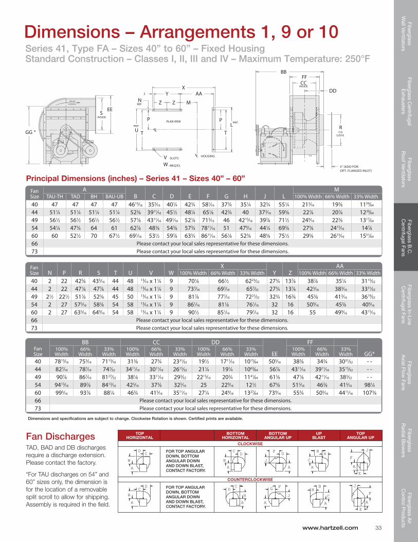
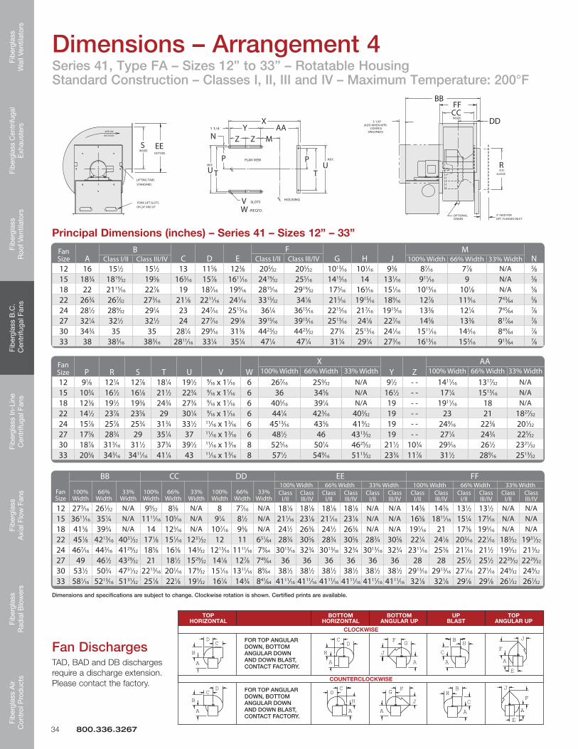
Fan DischargesTAD, BAD and DB discharges require a discharge extension. Please contact the factory.
*For TAU discharges on 54” and 60” sizes only, the dimension is for the location of a removable split scroll to allow for shipping. Assembly is required in the field.
www.hartzell.com 33
Fib
ergl
ass
Wal
l Ven
tilat
ors
Fibe
rgla
ss C
entr
ifuga
l E
xhau
ster
sFi
ber
glas
s R
oof V
entil
ator
sFi
ber
glas
s B
.C.
Cen
trifu
gal F
ans
Fib
ergl
ass
In-L
ine
Cen
trifu
gal F
ans
Fib
ergl
ass
Axi
al F
low
Fan
sFi
ber
glas
s R
adia
l Blo
wer
sFi
ber
glas
s A
ir C
ontr
ol P
rod
ucts
Series 41, Type FA – Sizes 12” to 33” – Rotatable Housing Standard Construction – Classes I, II, III and IV – Maximum Temperature: 200°F
Dimensions – Arrangement 4
Principal Dimensions (inches) – Series 41 – Sizes 12” – 33”
Dimensions and specifications are subject to change. Clockwise rotation is shown. Certified prints are available.
JF
AE
JF
AE
CA
HB
C
F G
A
HB
A
G F
JD
H
C
A
CDJ
AHA
C
D
B
A
A
B
D
C
TOP BOTTOM BOTTOM UP TOP HORIZONTAL HORIZONTAL ANGULARUP BLAST ANGULARUP
FOR TOP ANGULAR DOWN, BOTTOM ANGULAR DOWN AND DOWN BLAST, CONTACT FACTORY.
COUNTERCLOCKWISE
JF
AE
JF
AE
CA
HB
C
F G
A
HB
A
G F
JD
H
C
A
CDJ
AHA
C
D
B
A
A
B
D
C
CLOCKWISE
FOR TOP ANGULAR DOWN, BOTTOM ANGULAR DOWN AND DOWN BLAST, CONTACT FACTORY.
R
DDCCFF
BB
EESINSIDE
OUTSIDE
INSIDE
O.D.SLEEVE
3" (ADD FOROPT. FLANGED INLET
3 1/8"(ADD WHEN MTR.
COVER ISSPECIFIED)
FORK LIFT SLOTSON 24" AND UP
LIFTING TABS
STANDARD
OPTIONALDRAIN
1 1/4
-SLOTS
-REQ'D.
CL
CL HOUSING
PLAN VIEW REF.
REF.
TUP
VW
N ZY
M
XAA
Z
UT
P
ROTATION
AIRFLOW
Fan Size A
BC D E
FG H J
MNClass I/II Class III/IVClass I/II Class III/IV 100% Width 66% Width 33% Width
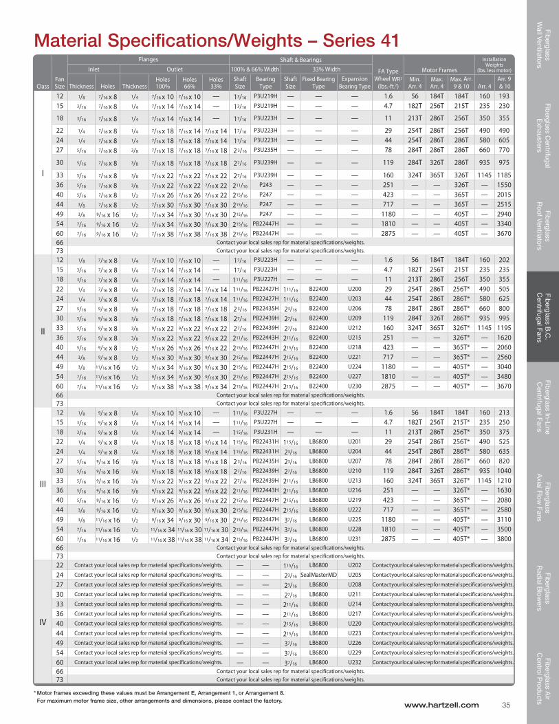
* Motor frames exceeding these values must be Arrangement E, Arrangement 1, or Arrangement 8. For maximum motor frame size, other arrangements and dimensions, please contact the factory.
ClassFan Size
Flanges Shaft & Bearings
FA Type Wheel WR2
(lbs.-ft.2)
Motor Frames
Installation Weights
(lbs. less motor)Inlet Outlet 100% & 66% Width 33% Width
Thickness Holes ThicknessHoles 100%
Holes 66%
Holes 33%
Shaft Size
Bearing Type
Shaft Size
Fixed Bearing Type
Expansion Bearing Type
Min. Arr. 4
Max. Arr. 4
Max. Arr. 9 & 10 Arr. 4
Arr. 9 & 10
I
12 1/8 7/16 x 8 1/4 7/16 x 10 7/16 x 10 — 13/16 P3U219H — — — 1.6 56 184T 184T 160 19315 3/16 7/16 x 8 1/4 7/16 x 14 7/16 x 14 — 13/16 P3U219H — — — 4.7 182T 256T 215T 235 230
18 3/16 7/16 x 8 1/4 7/16 x 14 7/16 x 14 — 17/16 P3U223H — — — 11 213T 286T 256T 350 355
22 1/4 7/16 x 8 1/4 7/16 x 18 7/16 x 14 7/16 x 14 17/16 P3U223H — — — 29 254T 286T 256T 490 49024 1/4 7/16 x 8 1/4 7/16 x 18 7/16 x 18 7/16 x 14 17/16 P3U223H — — — 44 254T 286T 286T 580 60527 5/16 7/16 x 8 3/8 7/16 x 18 7/16 x 18 7/16 x 18 2 3/16 P3U235H — — — 78 284T 286T 286T 660 770
30 5/16 7/16 x 8 3/8 7/16 x 18 7/16 x 18 7/16 x 18 27/16 P3U239H — — — 119 284T 326T 286T 935 975
33 5/16 7/16 x 8 3/8 7/16 x 22 7/16 x 22 7/16 x 22 27/16 P3U239H — — — 160 324T 365T 326T 1145 118536 5/16 7/16 x 8 3/8 7/16 x 22 7/16 x 22 7/16 x 22 211/16 P243 — — — 251 — — 326T — 155040 5/16 7/16 x 8 1/2 7/16 x 26 7/16 x 26 7/16 x 22 215/16 P247 — — — 423 — — 365T — 201544 3/8 7/16 x 8 1/2 7/16 x 30 7/16 x 30 7/16 x 30 215/16 P247 — — — 717 — — 365T — 251549 3/8 9/16 x 16 1/2 7/16 x 34 7/16 x 30 7/16 x 30 215/16 P247 — — — 1180 — — 405T — 294054 7/16 9/16 x 16 1/2 7/16 x 34 7/16 x 30 7/16 x 30 215/16 PB22447H — — — 1810 — — 405T — 334060 7/16 9/16 x 16 1/2 7/16 x 38 7/16 x 38 7/16 x 38 215/16 PB22447H — — — 2875 — — 405T — 367066 Contact your local sales rep for material specifications/weights.73 Contact your local sales rep for material specifications/weights.
II
12 1/8 7/16 x 8 1/4 7/16 x 10 7/16 x 10 — 17/16 P3U223H — — — 1.6 56 184T 184T 160 20215 3/16 7/16 x 8 1/4 7/16 x 14 7/16 x 14 — 17/16 P3U223H — — — 4.7 182T 256T 215T 235 23518 3/16 7/16 x 8 1/4 7/16 x 14 7/16 x 14 — 111/16 P3U227H — — — 11 213T 286T 256T 350 35522 1/4 7/16 x 8 1/4 7/16 x 18 7/16 x 14 7/16 x 14 111/16 PB22427H 111/16 B22400 U200 29 254T 286T 256T* 490 50524 1/4 7/16 x 8 1/4 7/16 x 18 7/16 x 18 7/16 x 14 111/16 PB22427H 111/16 B22400 U203 44 254T 286T 286T* 580 62527 5/16 9/16 x 8 3/8 7/16 x 18 7/16 x 18 7/16 x 18 2 3/16 PB22435H 23/16 B22400 U206 78 284T 286T 286T* 660 80030 5/16 9/16 x 8 3/8 7/16 x 18 7/16 x 18 7/16 x 18 27/16 PB22439H 27/16 B22400 U209 119 284T 326T 286T* 935 99533 5/16 9/16 x 8 3/8 9/16 x 22 9/16 x 22 9/16 x 22 27/16 PB22439H 27/16 B22400 U212 160 324T 365T 326T* 1145 119536 5/16 9/16 x 8 3/8 9/16 x 22 9/16 x 22 9/16 x 22 211/16 PB22443H 211/16 B22400 U215 251 — — 326T* — 162040 5/16 9/16 x 8 1/2 9/16 x 26 9/16 x 26 9/16 x 22 215/16 PB22447H 215/16 B22400 U218 423 — — 365T* — 206044 3/8 9/16 x 8 1/2 9/16 x 30 9/16 x 30 9/16 x 30 215/16 PB22447H 215/16 B22400 U221 717 — — 365T* — 256049 3/8 11/16 x 16 1/2 9/16 x 34 9/16 x 30 9/16 x 30 215/16 PB22447H 215/16 B22400 U224 1180 — — 405T* — 304054 7/16 11/16 x 16 1/2 9/16 x 34 9/16 x 30 9/16 x 30 215/16 PB22447H 215/16 B22400 U227 1810 — — 405T* — 348060 7/16 11/16 x 16 1/2 9/16 x 38 9/16 x 38 9/16 x 34 215/16 PB22447H 215/16 B22400 U230 2875 — — 405T* — 367066 Contact your local sales rep for material specifications/weights.73 Contact your local sales rep for material specifications/weights.
III
12 1/8 9/16 x 8 1/4 9/16 x 10 9/16 x 10 — 111/16 P3U227H — — — 1.6 56 184T 184T 160 21315 3/16 9/16 x 8 1/4 9/16 x 14 9/16 x 14 — 111/16 P3U227H — — — 4.7 182T 256T 215T* 235 25018 3/16 9/16 x 8 1/4 9/16 x 14 9/16 x 14 — 115/16 P3U231H — — — 11 213T 286T 256T* 350 37522 1/4 9/16 x 8 1/4 9/16 x 18 9/16 x 18 9/16 x 14 115/16 PB22431H 115/16 LB6800 U201 29 254T 286T 256T* 490 52524 1/4 9/16 x 8 1/4 9/16 x 18 9/16 x 18 9/16 x 14 115/16 PB22431H 23/16 LB6800 U204 44 254T 286T 286T* 580 63527 5/16 9/16 x 16 3/8 9/16 x 18 9/16 x 18 9/16 x 18 2 3/16 PB22435H 23/16 LB6800 U207 78 284T 286T 286T* 660 82030 5/16 9/16 x 16 3/8 9/16 x 18 9/16 x 18 9/16 x 18 27/16 PB22439H 27/16 LB6800 U210 119 284T 326T 286T* 935 104033 5/16 9/16 x 16 3/8 9/16 x 22 9/16 x 22 9/16 x 22 27/16 PB22439H 211/16 LB6800 U213 160 324T 365T 326T* 1145 121036 5/16 9/16 x 16 3/8 9/16 x 22 9/16 x 22 9/16 x 22 211/16 PB22443H 211/16 LB6800 U216 251 — — 326T* — 163040 5/16 9/16 x 16 1/2 9/16 x 26 9/16 x 26 9/16 x 22 215/16 PB22447H 215/16 LB6800 U219 423 — — 365T* — 208044 3/8 9/16 x 16 1/2 9/16 x 30 9/16 x 30 9/16 x 30 215/16 PB22447H 215/16 LB6800 U222 717 — — 365T* — 258049 3/8 11/16 x 16 1/2 9/16 x 34 9/16 x 30 9/16 x 30 215/16 PB22447H 37/16 LB6800 U225 1180 — — 405T* — 311054 7/16 11/16 x 16 1/2 11/16 x 34 11/16 x 30 11/16 x 30 215/16 PB22447H 37/16 LB6800 U228 1810 — — 405T* — 350060 7/16 11/16 x 16 1/2 11/16 x 38 11/16 x 38 11/16 x 34 215/16 PB22447H 37/16 LB6800 U231 2875 — — 405T* — 380066 Contact your local sales rep for material specifications/weights.73 Contact your local sales rep for material specifications/weights.
IV
22 Contact your local sales rep for material specifications/weights. — — 115/16 LB6800 U202 Contact your local sales rep for material specifications/weights.
24 Contact your local sales rep for material specifications/weights. — — 23/16 Seal Master MD U205 Contact your local sales rep for material specifications/weights.
27 Contact your local sales rep for material specifications/weights. — — 23/16 LB6800 U208 Contact your local sales rep for material specifications/weights.
30 Contact your local sales rep for material specifications/weights. — — 27/16 LB6800 U211 Contact your local sales rep for material specifications/weights.
33 Contact your local sales rep for material specifications/weights. — — 211/16 LB6800 U214 Contact your local sales rep for material specifications/weights.
36 Contact your local sales rep for material specifications/weights. — — 211/16 LB6800 U217 Contact your local sales rep for material specifications/weights.
40 Contact your local sales rep for material specifications/weights. — — 215/16 LB6800 U220 Contact your local sales rep for material specifications/weights.
44 Contact your local sales rep for material specifications/weights. — — 215/16 LB6800 U223 Contact your local sales rep for material specifications/weights.
49 Contact your local sales rep for material specifications/weights. — — 37/16 LB6800 U226 Contact your local sales rep for material specifications/weights.
54 Contact your local sales rep for material specifications/weights. — — 37/16 LB6800 U229 Contact your local sales rep for material specifications/weights.
60 Contact your local sales rep for material specifications/weights. — — 37/16 LB6800 U232 Contact your local sales rep for material specifications/weights.
66 Contact your local sales rep for material specifications/weights.73 Contact your local sales rep for material specifications/weights.
Fib
ergl
ass
Wal
l Ven
tilat
ors
Fibe
rgla
ss C
entr
ifuga
l E
xhau
ster
sFi
ber
glas
s R
oof V
entil
ator
sFi
ber
glas
s B
.C.
Cen
trifu
gal F
ans
Fib
ergl
ass
In-L
ine
Cen
trifu
gal F
ans
Fib
ergl
ass
Axi
al F
low
Fan
sFi
ber
glas
s R
adia
l Blo
wer
sFi
ber
glas
s A
ir C
ontr
ol P
rod
ucts
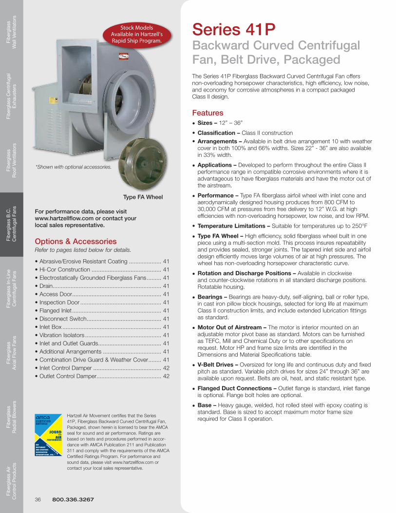
Series 41PBackward Curved Centrifugal Fan, Belt Drive, PackagedThe Series 41P Fiberglass Backward Curved Centrifugal Fan offers non-overloading horsepower characteristics, high efficiency, low noise, and economy for corrosive atmospheres in a compact packaged Class II design.
Features• Sizes – 12” – 36”
•Classification – Class II construction •Arrangements – Available in belt drive arrangement 10 with weather coverinboth100%and66%widths.Sizes22”-36”arealsoavailable in33%width.
• Applications – Developed to perform throughout the entire Class II performance range in compatible corrosive environments where it is advantageous to have fiberglass materials and have the motor out of the airstream.
• Performance – Type FA fiberglass airfoil wheel with inlet cone and aerodynamically designed housing produces from 800 CFM to 30,000 CFM at pressures from free delivery to 12” W.G. at high efficiencies with non-overloading horsepower, low noise, and low RPM.
• TypeFAWheel– High efficiency, solid fiberglass wheel built in one piece using a multi-section mold. This process insures repeatability and provides sealed, stronger joints. The tapered inlet side and airfoil design efficiently moves large volumes of air at high pressures. The wheel has non-overloading horsepower characteristic curve.
• Rotation and Discharge Positions – Available in clockwise and counter-clockwise rotations in all standard discharge positions. Rotatable housing.
• Bearings – Bearings are heavy-duty, self-aligning, ball or roller type, in cast iron pillow block housings, selected for long life at maximum Class II construction limits, and include extended lubrication fittings as standard.
• Motor Out of Airstream – The motor is interior mounted on an adjustable motor pivot base as standard. Motors can be furnished as TEFC, Mill and Chemical Duty or to other specifications on request. Motor HP and frame size limits are identified in the Dimensions and Material Specifications table.
• V-Belt Drives – Oversized for long life and continuous duty and fixed pitch as standard. Variable pitch drives for sizes 24” through 36” are available upon request. Belts are oil, heat, and static resistant type.
• Flanged Duct Connections – Outlet flange is standard, inlet flange is optional. Flange bolt holes are optional.
• Base – Heavy gauge, welded, hot rolled steel with epoxy coating is standard. Base is sized to accept maximum motor frame size required for Class II operation.
Options & AccessoriesRefer to pages listed below for details.
Stock Models Available in Hartzell’s Rapid Ship Program.
Hartzell Air Movement certifies that the Series 41P, Fiberglass Backward Curved Centrifugal Fan, Packaged, shown herein is licensed to bear the AMCA seal for sound and air performance. Ratings are based on tests and procedures performed in accor-dance with AMCA Publication 211 and Publication 311 and comply with the requirements of the AMCA Certified Ratings Program. For performance and sound data, please visit www.hartzellflow.com or contact your local sales representative.
For performance data, please visit www.hartzellflow.com or contact your local sales representative.
36 800.336.3267
Fiberglass
Wall Ventilators
Fiberglass Centrifugal
Exhausters
Fiberglass
Roof Ventilators
Fiberglass B
.C.
Centrifugal Fans
Fiberglass In-Line
Centrifugal Fans
Fiberglass
Axial Flow
FansFib
erglass R
adial B
lowers
Fiberglass A
ir C
ontrol Prod
ucts
www.hartzell.com 37
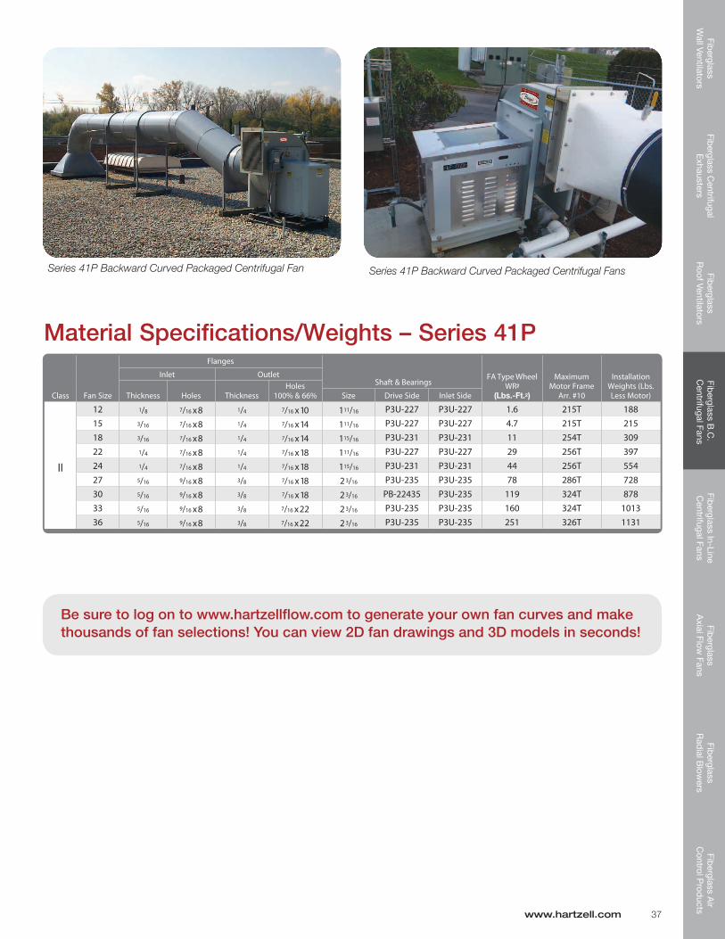
Class Fan Size
Flanges
FA Type Wheel WR2
(Lbs.-Ft.2)
Maximum Motor Frame
Arr. #10
Installation Weights (Lbs. Less Motor)
Inlet Outlet
Thickness Holes ThicknessHoles
100% & 66% Size Drive Side Inlet Side
II
12 1/8 7/16 x 8 1/4 7/16 x 10 111/16 P3U-227 P3U-227 1.6 215T 18815 3/16 7/16 x 8 1/4 7/16 x 14 111/16 P3U-227 P3U-227 4.7 215T 21518 3/16 7/16 x 8 1/4 7/16 x 14 115/16 P3U-231 P3U-231 11 254T 30922 1/4 7/16 x 8 1/4 7/16 x 18 111/16 P3U-227 P3U-227 29 256T 39724 1/4 7/16 x 8 1/4 7/16 x 18 115/16 P3U-231 P3U-231 44 256T 55427 5/16 9/16 x 8 3/8 7/16 x 18 2 3/16 P3U-235 P3U-235 78 286T 72830 5/16 9/16 x 8 3/8 7/16 x 18 2 3/16 PB-22435 P3U-235 119 324T 87833 5/16 9/16 x 8 3/8 7/16 x 22 2 3/16 P3U-235 P3U-235 160 324T 101336 5/16 9/16 x 8 3/8 7/16 x 22 2 3/16 P3U-235 P3U-235 251 326T 1131
Shaft & Bearings
Material Specifications/Weights – Series 41P
Series 41P Backward Curved Packaged Centrifugal Fan Series 41P Backward Curved Packaged Centrifugal Fans
Be sure to log on to www.hartzellflow.com to generate your own fan curves and make thousands of fan selections! You can view 2D fan drawings and 3D models in seconds!
Fib
ergl
ass
Wal
l Ven
tilat
ors
Fibe
rgla
ss C
entr
ifuga
l E
xhau
ster
sFi
ber
glas
s R
oof V
entil
ator
sFi
ber
glas
s B
.C.
Cen
trifu
gal F
ans
Fib
ergl
ass
In-L
ine
Cen
trifu
gal F
ans
Fib
ergl
ass
Axi
al F
low
Fan
sFi
ber
glas
s R
adia
l Blo
wer
sFi
ber
glas
s A
ir C
ontr
ol P
rod
ucts
2"
REF.
INSIDE
O.D.
INSIDE
MAX.
HOUSING
LCREF.
PLAN VIEW
-REQ'D.
-SLOTSCL
EE
U
SN
XAAY
MZZ
P
T
P
VW
TL R
DD
BB
CCFF
Principal Dimensions (inches) – Series 41P – Sizes 12” – 36”
Series 41P, Type FA – Sizes 12” to 36” – Rotatable Housing Standard Construction – Class II – Maximum Temperature: 250°F
Dimensions – Arrangement 10
Fan DischargesScrolls are rotatable. BH and BAU discharges require a height adjusting sub-base. TAD, BAD and DB discharges require a discharge extension. Please contact the factory.
JF
AE
JF
AE
CA
HB
C
F G
A
HB
A
G F
JD
H
C
A
CDJ
AHA
C
D
B
A
A
B
D
C
TOP BOTTOM BOTTOM UP TOP HORIZONTAL HORIZONTAL ANGULARUP BLAST ANGULARUP
FOR TOP ANGULAR DOWN, BOTTOM ANGULAR DOWN AND DOWN BLAST, CONTACT FACTORY.
COUNTERCLOCKWISE
JF
AE
JF
AE
CA
HB
C
F G
A
HB
A
G F
JD
H
C
A
CDJ
AHA
C
D
B
A
A
B
D
C
CLOCKWISE
FOR TOP ANGULAR DOWN, BOTTOM ANGULAR DOWN AND DOWN BLAST, CONTACT FACTORY.
Dimensions and specifications are subject to change. Clockwise Rotation is shown. Certified prints are available.
Series 41UBackward Curved Centrifugal Fan, Belt Drive, Packaged, SWSIThe Series 41U Backward Curved Centrifugal Fan offers non-overloading horsepower characteristics, high efficiency, low noise and economy for most applications where corrosive elements exist in fume and vapor form. It is available in SWSI (single width single inlet) only.
Features• Sizes – 12”, 18”, and 24”
• Arrangement – Available in belt drive arrangement 10, SWSI
• Applications – Developed to perform in compatible corrosive environments where it is advantageous to have fiberglass materials and have the motor out of the airstream.
• Performance – 700 CFM to 10,300 CFM at static pressures to 6” W.G.
• TypeFAWheel– High efficiency, solid fiberglass wheel built in one piece using a multi-section mold. This process insures repeatability and provides sealed, stronger joints. The tapered inlet side and airfoil design efficiently moves large volumes of air at high pressures. The wheel has non-overloading horsepower characteristic curve.
• Rotation and Discharge – Available in clockwise or counterclockwise rotation in all eight discharge positions. Rotatable housing.
• Bearings – Bearings on belt drive units are heavy duty, deep row radial ball, self-aligning and shielded in cast iron housings. Long inner races insure even load distribution, providing a high radial and thrust load capacity. Bearings are relubricable for continuous service with lubrication tubes extended to the exterior of fan base as necessary.
• Motor Out of Airstream – The motor is exterior mounted on an adjustable motor pivot base as standard. Motors can be furnished as TEFC, Mill and Chemical Duty or to other specifications on request.
• V-Belt Drives – Oversized for long life and continuous duty and fixed pitch as standard. Variable pitch drives are available upon request. Belts are oil, heat, and static resistant type.
• Fan Inlets and Outlets – Straight inlet and outlet connections are provided for easy “slip-fit” connection to ducting.
• Base – Heavy gauge, welded, hot rolled steel with epoxy coating is standard.
Options & AccessoriesRefer to pages listed below for details.
Hartzell Air Movement certifies that the Series 41U, FRP Backward Curved Centrifugal Fan, Packaged, shown herein is licensed to bear the AMCA seal for sound and air performance. Ratings are based on tests and procedures performed in accordance with AMCA Publication 211 and Publication 311 and comply with the requirements of the AMCA Certified Ratings Program. For performance and sound data, please visit www.hartzellflow.com or contact your local sales representative.
www.hartzell.com 39
Scan the QR code to visit our Facebook page, where you can keep up to date with happenings at Hartzell!
Fib
ergl
ass
Wal
l Ven
tilat
ors
Fibe
rgla
ss C
entr
ifuga
l E
xhau
ster
sFi
ber
glas
s R
oof V
entil
ator
sFi
ber
glas
s B
.C.
Cen
trifu
gal F
ans
Fib
ergl
ass
In-L
ine
Cen
trifu
gal F
ans
Fib
ergl
ass
Axi
al F
low
Fan
sFi
ber
glas
s R
adia
l Blo
wer
sFi
ber
glas
s A
ir C
ontr
ol P
rod
ucts
6 REQ'D9/16 DIA.
1"2
O.D.
OUTSIDE
OUTSIDE
REF.
REF.
REF.
HOUSINGLC
LC
Fan DischargesFor angular and/or down blast discharges, please contact the factory when discharge flanges are required.
J
F
EH
B
C
JCB
A KA
EG
A A
DC
A
B
CD
A
H
BH
C
A
JF
A
E
E
GF
A
EF
A
BH
D
A
BH
D
A
J
KA
EG
CD
A
H
G
GF
JA
GF
J
A
D
TOP TOP DOWN BOTTOM BOTTOM BOTTOM UP TOP HORIZONTAL ANGULARDOWN BLAST ANGULARDOWN HORIZONTAL ANGULARUP BLAST ANGULARUP
Series 41U, Type FA – Sizes 12” to 24” – Rotatable Housing Maximum Temperature: 200°F
Dimensions – Arrangement 10
40 800.336.3267
Call and speak to your local Hartzell Air Movement sales representative about one of our FRP centrifugal fans today!
Fiberglass
Wall Ventilators
Fiberglass Centrifugal
Exhausters
Fiberglass
Roof Ventilators
Fiberglass B
.C.
Centrifugal Fans
Fiberglass In-Line
Centrifugal Fans
Fiberglass
Axial Flow
FansFib
erglass R
adial B
lowers
Fiberglass A
ir C
ontrol Prod
ucts
www.hartzell.com 41
Options and AccessoriesFlanged InletA fiberglass inlet flange is available. Flanges are drilled upon request. Note: A flanged and drilled inlet is required when an inlet control damper is used.
Flanged OutletFlanged outlets are standard on the Series 41 and 41P. A bolt-on flanged outlet is available for the Series 41U. Drill flanges are available on all series.
Disconnect SwitchAn on/off switch mounted to the unit to provide safety during maintenance.
Inlet BoxConstructed of solid fiberglass, an inlet box improves entry conditions and minimizes losses, which are generally associated with duct elbows at the fan inlet. Inlet boxes are designed for specific applications. Please contact factory.
Vibration IsolatorsRubber-in-shear or spring type isolators are available.
Inlet and Outlet GuardsA spiral ring guard can be furnished for the inlet side and a wire mesh guard can be furnished for the outlet side. Series 41 and 41P guards are constructed of epoxy coated steel. Series 41U guards are constructed of alphacoat coated steel.
Additional ArrangementsArrangement 8 and other arrangements (not shown in this catalog) are available. Please contact the factory.
Combination Drive Guard & Weather CoverConstructed of epoxy coated steel. Covers motor and shaft sheaves as well as belts. Guards the drive and provides weather protection. Please specify fan arrangement.
Arrangement 9 Series 41
Arrangement 10 Series41P&41U
Abrasive/Erosive Resistant CoatingHartKoate is an abrasive/erosive resistant coating developed by Hartzell Air Movement for application in environments where abrasive/erosive conditions may exist. HartKoate helps prevent premature deterioration of equipment in environments where uncoated fans may fail.
HartKoate is applied to a 50-60 mil thickness suitable for temperaturesto200°F.
HartKoate is particularly appropriate for use when water mist and/or abrasive particles exist in the airstream.
Contact your Hartzell representative for further details concerning the application of HartKoate coating to fiberglass fans in corrosive atmospheres.
Hi-Cor ConstructionAll airstream surfaces exposed to corrosive environment will be protected with a layer of Synthetic (Nexus) surfacing veil. An additional final coat of resin will be applied for extra corrosion resistance.
When Hi-Cor construction is required, the factory should be consulted concerning the corrosive environment involved.
Electrostatically GroundedFor applications in which fiberglass products are handling gas fumes that are not only corrosive but also potentially explo-sive, the equipment should be specially constructed to control and remove static electricity. Interior airstream surfaces can be coated with a “carbon rich” resin coat.
Grounding straps are secured from the side of the housing to the fan’s steel base. All that remains to effectively ground the airstream is to ground the fan base at the time of installation.
DrainFor Series 41 & 41P: Fiberglass bulk head fitting assembled in housing. 1” NPT female threaded fitting. Plug not provided.
For Series 41U: Fiberglass half coupling assembled in housing. 1” NPT female threaded fitting.
Access DoorRaised, bolted door held in place with zinc plated bolts and gasketed for a tight seal.
Inspection DoorAllows for periodic visual inspection of the wheel. Constructed of fiberglass, fastened with stainless steel bolts and gasketed for tight seal.
Fib
ergl
ass
Wal
l Ven
tilat
ors
Fibe
rgla
ss C
entr
ifuga
l E
xhau
ster
sFi
ber
glas
s R
oof V
entil
ator
sFi
ber
glas
s B
.C.
Cen
trifu
gal F
ans
Fib
ergl
ass
In-L
ine
Cen
trifu
gal F
ans
Fib
ergl
ass
Axi
al F
low
Fan
sFi
ber
glas
s R
adia
l Blo
wer
sFi
ber
glas
s A
ir C
ontr
ol P
rod
ucts
Arrangement 1 Sub-BaseCommon structural support for an Arrangement 1 fan and motor. Please specify motor mounting position. Epoxy coated steel construction. Series 41 only.
Shaft Guard Arrangement 9 or 1
Belt Drive Guard Arrangement 9
Drive GuardsEncloses the drive assembly while permitting circulation of ambient air. Standard features include: tach opening, belt tension openings and adjustable length. Series 41 only.
Arrangement E Motor BaseAccommodates a larger frame size motor than the standard arrangement 9 base. Series 41 only.
Options and Accessories
42 800.336.3267
Inlet Control DamperDampers are mounted on the blower’s drilled inlet flange to increase the efficiency of the system and permit control of air volume. Dampers are epoxy coated or stainless steel construction.
Outlet Control DamperDampers are mounted directly on the blower outlet to control the volume of air delivered to the system. Opposed and parallel blade dampers are available in steel, stainless steel, coated steel and solid fiberglass.
Parallel Blade TypeBest suited for applications requiring accurate air volume in a range from wide opento75%open.Usuallyusedfor balancing the system or for modulated control when pressure drop is variable.
Opposed Blade TypeBest suited for control over a broad range of air volume with more precise control.
Both types of outlet control dampers are available in three classifications:
Class I – Maximum static pressure: 5” S.P. Maximum velocity: 3,900 FPM
Class II – Maximum static pressure: 81⁄2” S.P. Maximum velocity: 5,100 FPM
Class III – Maximum static pressure: 20” S.P. Maximum velocity: 6,000 FPM
Discharge Backdraft DamperAutomatic gravity operated backdraft damper eliminates backflow of air when fan is not operating. Series 41U only.
Parallel Blade
Opposed Blade
Follow Hartzell Air Movement on LinkedIn!
Quality • Value • Commitment
SERIES 40
Fiberglass In-Line Centrifugal Fans
Fib
ergl
ass
Wal
l Ven
tilat
ors
Fibe
rgla
ss C
entr
ifuga
l E
xhau
ster
sFi
ber
glas
s R
oof V
entil
ator
sFi
ber
glas
s B
.C.
Cen
trifu
gal F
ans
Fib
ergl
ass
In-L
ine
Cen
trifu
gal F
ans
Fib
ergl
ass
Axi
al F
low
Fan
sFi
ber
glas
s R
adia
l Blo
wer
sFi
ber
glas
s A
ir C
ontr
ol P
rod
ucts
In-Line Centrifugal Fan Classifications
In-Line Centrifugal Fan Arrangements
Arrangement 1 For belt drive. Impeller overhung on a shaft supported by bearing mounted with casing. Motor mounted independent of casing. Horizontal discharge.
Arrangement 9 – PRV When desirable, the in-line centrifugal fan can be mounted as a power roof ventilator for exhaust application. Together with a stack cap and panel, the three elements combine to provide an efficient roof exhauster. Back draft dampers in the stack cap offer weatherproof closure for vertical air discharge.
Vertical Mounting Another method for mounting vertical fans is shown in the view above. Specify fan to be furnished with ceiling mounting brackets, floor mounting brackets or both.Specify either upblast or downblast discharge for vertically mounted fans.
Arrangement 9 For belt drive. Impeller overhung on a shaft supported by bearings mounted with casing. Fan may be rotated to achieve motor positions. For horizontal and vertical discharge. Duct mounting shown.Arrangement 9 can be furnished with supports for floor, wall or ceiling mounting. The position of these supports determines which motor locations are available for motor placement. Generally motor locations 135, 180 and 225 are not available on floor, wall or inverted ceiling mounted fans and motor locations 45, 90, 270 & 315 may not be available for ceiling hung fans.
Motor Shown in Position A
View Facing Outlet
Motor Left
View Facing Outlet
360
45
90
135
180
225
270
315
View Facing Outlet
Hartzell Series 40 Fiberglass Backward Curved Centrifugal Fans, Type FA, are designed and classified with two classes of construction. Class I construction covers light to medium duty performance. Class II construction is required for maximum fan performance, but is inappropriate under light duty applications due to inadequate loading of the bearings.
Series 40 Fans are available in Class I and II construction in 100%widthand66%width.Theseparametersareexplainedin the following table.
FANCLASS PERFORMANCERANGE
I LighttoMediumDuty
II MaximumFanPerformance
Motor Left
View Facing Outlet
360
45
90
135
180
225
270
315
View Facing Outlet
44 800.336.3267
Fiberglass
Wall Ventilators
Fiberglass Centrifugal
Exhausters
Fiberglass
Roof Ventilators
Fiberglass B
.C.
Centrifugal Fans
Fiberglass In-Line
Centrifugal Fans
Fiberglass
Axial Flow
FansFib
erglass R
adial B
lowers
Fiberglass A
ir C
ontrol Prod
ucts
The Series 40 In-Line Centrifugal Fan offers non-overloading horsepower, high efficiency, low noise, and economy for corrosive atmospheres. It is unique in the fan and blower industry. It combines the design advantages of the axial flow fan with the performance characteristics of the centrifugal fan. The design saves space by incorporating a tubular housing, as opposed to a traditional scroll-type centrifugal housing, and allows for the unit to be installed directly in a duct system. The “tubular centrifugal” or in-line fan utilizes the Type FA backward curved, airfoil-bladed wheel in a vane-equipped housing and produces straight airflow with the same inlet and discharge dimensions.
Series 40Fiberglass In-Line Centrifugal Fan, Belt Drive
Features•Applications – Developed for compatible corrosive applications where it is advantageous to have fiberglass materials and have the motor out of the airstream.
•Performance – Type FA fiberglass airfoil wheel with inlet cone and housing built in aerodynamically designed straightening vanes produces from 800 CFM to 90,000 CFM at pressures from free delivery to 12” W.G. at high efficiencies with non-overloading horsepower, low noise, and low RPM. Power Ratings (BHP) includes Belt Drive Losses. •Temperature–Suitablefortemperaturesupto200°F
•Sizes – 12” – 60” •Classifications –AvailableinClassIandIIinboth100%and 66%widths.•Arrangements – Available in arrangements 9 and 1. Also available in a Power Roof Ventilator configuration. • FRP Construction – All structural parts in the airstream are fiberglass and resin. All fiberglass surfaces are protected with a minimum 10-mil thickness of chemical, flame, and ultraviolet resistant resin. – FRP Components & Housing – Constructed of fiberglass and vinylester corrosive resistant polyester resin with a Class I flame spread rate of 25 or less. – Wheel – Constructed of fiberglass and Ashland Derakane 510-A corrosion resistant vinylester resin with a Class Il flame spread rate of 30 or less. See Corrosion Resistance Guide on page 79 for resin characteristics. Other resins are available.
•TypeFAWheel– High efficiency, solid fiberglass wheel built in one piece using a multi-section mold. This process insures repeatability and provides sealed, stronger joints. The tapered inlet side and airfoil design efficiently moves large volumes of air at high pressures. The wheel has non-overloading horsepower characteristic curve. • Shafts – Shafts are 304 SS and are turned, ground, polished, and keyed at both ends with a fiberglass sleeve in the airstream. Shafts are sized to operate well below critical speed. 316 SS or monel shafting is available as an option at extra cost. •Bearings – Bearings are heavy duty, deep row radial ball or double row spherical roller type self-aligning and shielded in cast iron housings. Long inner races insure even load distribution, providing a high radial and thrust load capacity. Bearings have a minimum L-50 life of 500,000 hours for horizontal fans and 250,000 hours for vertical fans. Bearings are relubricable for continuous service and include extended lubrication fittings as standard. •Shaft Seal – A fiberglass and neoprene shaft seal is placed where the shaft leaves the housing along with a neoprene shaft slinger between the seal and wheel on belt drive units. The seal is not gas tight.
Features continued on next page…
Hartzell Air Movement certifies that the Series 40, Fiberglass In-Line Centrifugal Fans, shown herein are licensed to bear the AMCA seal for sound and air performance. Ratings are based on tests and procedures performed in accordance with AMCA Publication 211 and Publication 311 and comply with the requirements of the AMCA Certified Ratings Program. For performance and sound data, please visit www.hartzellflow.com or contact your local sales representative.
Options & AccessoriesRefer to pages listed below for details.
For performance data, please visit www.hartzellflow.com or contact your local sales representative.
www.hartzell.com 45
Fib
ergl
ass
Wal
l Ven
tilat
ors
Fibe
rgla
ss C
entr
ifuga
l E
xhau
ster
sFi
ber
glas
s R
oof V
entil
ator
sFi
ber
glas
s B
.C.
Cen
trifu
gal F
ans
Fib
ergl
ass
In-L
ine
Cen
trifu
gal F
ans
Fib
ergl
ass
Axi
al F
low
Fan
sFi
ber
glas
s R
adia
l Blo
wer
sFi
ber
glas
s A
ir C
ontr
ol P
rod
ucts
Type FA WheelThe Type FA wheel is unique in the fan and blower industry. It is manufactured as a single fiberglass piece using a multi-section RTM mold, ensuring that each wheel is aerodynamically identical and provides reliable, repeatable performance without the variability of hand-made and taped components. The superior design is a result of a substantial investment in research, development, tooling, and manufacturing methods by Hartzell Air Movement.
Features – Type FA wheels are highly efficient with a tapered inlet side and airfoil blades and have a non-overloading horsepower characteristic curve. When used in conjunction with a precision inlet cone it efficiently moves large volumes of air at high pressures with low noise characteristics at low RPM.
Construction – Solid fiberglass, die formed and constructed with Ashland Derakane 510-A corrosion resistant vinylester resin. The fiberglass resin has a Class II flame spread rate of 30 or less. Special constructions are available for abrasive or extremely corrosive environments.
Balancing – Each wheel is electronically, statically and dynamically balanced according to the requirements of Fan Application Category BV-3 of AMCA ANSI Std. 204-96. Each wheel is also operationally tested and inspected before shipment.
Series 40 Features (cont.)•Hardware – Internal hardware (airstream) is encapsulated type 304 stainless steel. All external hardware (out of airstream) is zinc plated as standard. Where metal is subject to attack by the corrosive elements being handled, all metal parts can be resin-coated after assembly.
•Motor – The motor is exterior mounted out of the airstream on a fully adjustable platform-style motor base supported by an external housing assembly base. Open-end motors are standard. Motors larger than 30 HP will be shipped separately for mounting at the job site. Motor frame size limits are identified in the Principal Dimensions table.• V-BeltDrives–Oversized for long life and continuous duty. Variable pitch drives are a standard option for 10 HP and below and fixed pitch are a standard option above 10 HP. Belts are oil, heat, and static resistant type.
• Balancing – The fan is dynamically balanced to the requirements of Fan Application Category BV-3 of AMCA/ANSI Std. 204-96. All fans receive vibration test and inspection prior to shipment.
•Spark Resistant Construction – Available as an option.
•Protective Coatings – Available as an option for abrasive or extremely corrosive environments.
Hartzell offers the only fiberglass wheel available in a solid,
Dimensions and specifications are subject to change. Certified prints are available.
Size D V12 221⁄2 125⁄8
15 241⁄2 14
22 365⁄8 201⁄8
27 443⁄4 241⁄8
33 483⁄4 261⁄8
40 601⁄8 317⁄8
49 75 371⁄2
60 901⁄2 471⁄16
Principal Dimensions (inches) – Series 40 – Sizes 12” – 60”
Series 40, Type FA – Sizes 12” to 60” Standard Construction – Classes I & II – Maximum Temperature: 200°F
Dimensions – Arrangement 9
Material Specifications/Weight
Dimensions and specifications are subject to change. Certified prints are available. Installation weight is approximate and is less motor, drives and optional equipment.
Series 40
Class Fan Size Fan Shaft Drive Bearing Wheel Bearing 100% Inertia 66% Inertia
Installation Weight
100% 66%
I
12 13/16 P3-U219 P3-U219 1.6 1.4 93 93
15 13/16 F3-U219 F3-U219 4.7 4.2 146 144
22 23/16 F3-U235 F3-U235 29 25.1 312 307
27 115/16 F3-U231 F3-U231 78.2 67.8 537 526
33 23/16 F3-U235 F3-U235 160 140 672 657
40 211/16 F3-U243 F3-U243 423 368 962 935
49 215/16 F3-U247 F3-U247 1181 1033 1594 1545
60 33/16 F-B22451 F-B22451 2877 2472 2399 2308
II
12 13/16 PE-B22419 P3-U219 1.6 1.4 96 96
15 111/16 F3-U227 F3-U227 4.7 4.2 159 157
22 111/16 F-B22427 F-B22427 29 25.1 302 297
27 115/16 F-B22431 F-B22431 78.2 67.8 543 532
33 23/16 F-B22435 F-B22435 160 140 683 668
40 211/16 F-B22443 F-B22443 423 368 990 963
49 215/16 F-B22447 F-B22447 1181 1033 1611 1563
60 311/16 F-B22459 F-B22459 2877 2472 2507 2416
Mounting Feet (optional)
Fib
ergl
ass
Wal
l Ven
tilat
ors
Fibe
rgla
ss C
entr
ifuga
l E
xhau
ster
sFi
ber
glas
s R
oof V
entil
ator
sFi
ber
glas
s B
.C.
Cen
trifu
gal F
ans
Fib
ergl
ass
In-L
ine
Cen
trifu
gal F
ans
Fib
ergl
ass
Axi
al F
low
Fan
sFi
ber
glas
s R
adia
l Blo
wer
sFi
ber
glas
s A
ir C
ontr
ol P
rod
ucts
48 800.336.3267
Options and AccessoriesInspection DoorAllows for periodic visual inspection of the wheel. Constructed of fiberglass, fastened with stainless steel bolts and gasketed for tight seal.
Fiberglass Motor Cover Designed to fit fiberglass in-line centrifugal fans. The cover is solid fiberglass and die-formed with injection molded louvers.
Weather Cover Designed to fit belt drive in-line centrifugal fans. The cover is epoxy coated steel and vented. Specify horizontal or vertical mounting.
Belt Guard Covers motor sheave and belts outside the fan housing. Epoxy coated, steel construction.
Combination Motor Cover & Belt GuardDesigned to fit fiberglass in-line centrifugal fans. Constructed of epoxy coated steel and vented. Specify horizontal or vertical mounting.
Abrasive/Erosive Resistant CoatingHartKoate is an abrasive/erosive resistant coating developed by Hartzell Air Movement for application in environments where abrasive/erosive conditions may exist. HartKoate helps prevent premature deterioration of equipment in environments where uncoated fans may fail.
HartKoate is applied to a 50-60 mil thickness suitable for temperaturesto200°F.
HartKoate is particularly appropriate for use when water mist and/or abrasive particles exist in the airstream.
Contact your Hartzell representative for further details concerning the application of HartKoate coating to fiberglass fans in corrosive atmospheres.
Hi-Cor ConstructionAll airstream surfaces exposed to corrosive environment will be protected with a layer of Synthetic (Nexus) surfacing veil. An additional final coat of resin will be applied for extra corrosion resistance.
When Hi-Cor construction is required, the factory should be consulted concerning the corrosive environment involved.
Electrostatically GroundedFor applications in which fiberglass products are handling gas fumes that are not only corrosive but also potentially explosive, the equipment should be specially constructed to control and remove static electricity. Interior airstream surfaces can be coated with a “carbon rich” resin coat.
Grounding straps are secured from the side of the housing to the fan’s steel base. All that remains to effectively ground the airstream is to ground the fan base at the time of installation.
ASTM D4167-97 Construction(ASTM D4167-97, Standard Specification for Fiber-Reinforced Plastic Fans and Blowers.) For corrosive systems where ASTM construction is specified this construction option adds: synthetic veil and electrostatically conductive surface coating applied to airstream housing and impeller surfaces, special nameplates, and special final dynamic balancing to fan.
Companion FlangesDrilled to fit the flanges of the fan; allows for easy installation. Fiberglass construction.
DrainFiberglass bulkhead fitting assembled in housing, NPT female threaded fitting. 1” NPT on Series 40. Plug not provided.
Series 40 Fiberglass In-Line Centrifugal Fan at a wastewater treatment plant.
Fiberglass
Wall Ventilators
Fiberglass Centrifugal
Exhausters
Fiberglass
Roof Ventilators
Fiberglass B
.C.
Centrifugal Fans
Fiberglass In-Line
Centrifugal Fans
Fiberglass
Axial Flow
FansFib
erglass R
adial B
lowers
Fiberglass A
ir C
ontrol Prod
ucts
www.hartzell.com 49
Power Roof Ventilator
Dimensions and specifications are subject to change. Certified prints are available. Installation weight is approximate and is less motor, drives and optional equipment.
Note: Guy wire bracing must be provided by customer when necessary.
Mounting Feet/Ceiling Suspension Bolted to the inlet and discharge flanges, mounting feet allow for positioning of the duct fan on a floor, ceiling, wall or platform. Can be used with vibration isolators. Epoxy coated steel construction.
Vibration Isolators Rubber-in-shear or spring type isolators are available. When using vibration isolators, mounting feet or a panel must be specified.
Inlet Control DamperDampers are mounted on the blower’s drilled inlet flange to increase the efficiency of the system and permit control of air volume. Dampers are epoxy coated or stainless steel construction.
Roof Mounted Upblast Together with a fiberglass curb panel and fiberglass stack cap, the Hartzell Fiberglass In-Line Centrifugal Fan can be mounted as a roof exhauster. The stack cap has back draft dampers to provide a weather tight closure for vertical air discharge.
Hooded Roof VentilatorWhen required, the Hartzell Fiberglass In-Line Centrifugal Fan can be supplied with a fiberglass weather hood. These power roof ventilators can be used for intake or exhaust.
Inlet and Outlet Guards Constructed of epoxy coated steel. OSHA approved.
CAUTION: The drive assembly or the periphery of the blades of a fan less than seven (7) feet above the floor or working level must be guarded to be in accordance with OSHA regulations.
Quality • Value • Commitment
Fiberglass Axial Flow FansSERIES 28B
SERIES 28
SERIES 29B
SERIES 29
SERIES 34
SERIES 35
SERIES 35V
Fiberglass
Wall Ventilators
Fiberglass Centrifugal
Exhausters
Fiberglass
Roof Ventilators
Fiberglass B
.C.
Centrifugal Fans
Fiberglass In-Line
Centrifugal Fans
Fiberglass
Axial Flow
FansFib
erglass R
adial B
lowers
Fiberglass A
ir C
ontrol Prod
ucts
Standard Construction Features• FRP Construction – All structural parts in the airstream are fiberglass and resin. All fiberglass surfaces are protected with a minimum 10-mil thickness of chemical, flame, and ultraviolet resistant resin. Corrosion resistant vinylester resin, having a class l flame spread rate of 25 or less is used for all housings and propellers. •Hardware – All internal hardware (airstream) is Type 304 stainless steel and encapsulated. All external hardware (out of airstream) is zinc plated as standard. Where metal is subject to attack by the corrosive elements being handled, all metal parts can be resin-coated after assembly. •Propellers – One piece construction, die formed of individual laminations of cloth mat plus woven roving. Adjustable pitch propellers incorporate die-formed blades.
For Belt Drive Units: • Fan shafts – 304 stainless steel, turned, ground, polished, and keyed at both ends. Shafts are sized to operate well below critical speed. 316 stainless steel or monel shafting is available as an option at extra cost. •Shaft Seal –A fiberglass and neoprene shaft seal is placed where the shaft leaves the bearing cover along with a neoprene shaft slinger between the seal and wheel on belt drive units.•Bearings – Heavy duty, deep row radial ball or double row spherical roller type self-aligning and shielded in cast iron hous-ings. Long inner races insure even load distribution, providing a high radial and thrust load capacity. Bearings are relubricable for continuous service with lubrication tubes extended to the exterior of fan base as necessary. •Bearing covers – Sealed with foam gasket and bolted to the bearing base.•V-Belt Drives – Oversized for long life and continuous duty. Fixed pitch or variable pitch drives are available upon request. Belts are oil, heat, and static resistant type.
Fiberglass Axial Flow Fans
Performance Data Charts for axial flow fans with inlet and outlet ducts of the same diameter as the fan can be found at www.hartzellflow.com. Discharge cones may be used on the duct fans to adapt to larger diameters (see Fig. A). The result is a static pressure regain.
Table 2 shows the amount of additional static pressure capability, which results from using the discharge cone. Add the amount of .45 (VP1–VP2) to the fan’s static pressure.SP2 = SP1 + .45(VP1–VP2)
Thus, a fan selected for 4000 FPM O.V. at 3/4” SP using a size 18”-21” cone, the static pressure capability would be raised from .750” to .957” static pressure. Regain calculations are approximate and are not part of the AMCA certified ratings.
Discharge cones may also be used to transform large ducts to the fan inlet size (see Fig. B). Since these cones have gently tapered sides, the friction loss is negligible, about .08 x the difference in velocity pressures (see Table 2).
If the fan is to be used with ducts smaller in diameter than the unit (see Fig. C), the difference in velocity pressure across the cone must be added to the static pressure for which the fan is used.
Table 2: Corresponding Air Velocities for Various Pressures in Inches of Water (Air Weight = .07488 lbs. per cu. ft.)
www.hartzell.com 51
Fib
ergl
ass
Wal
l Ven
tilat
ors
Fibe
rgla
ss C
entr
ifuga
l E
xhau
ster
sFi
ber
glas
s R
oof V
entil
ator
sFi
ber
glas
s B
.C.
Cen
trifu
gal F
ans
Fib
ergl
ass
In-L
ine
Cen
trifu
gal F
ans
Fib
ergl
ass
Axi
al F
low
Fan
sFi
ber
glas
s R
adia
l Blo
wer
sFi
ber
glas
s A
ir C
ontr
ol P
rod
ucts
Hartzell Series 28B and 29B Fiberglass Axial Flow Bifurcated Fans are designed and built to be used in a variety of corrosive applications. They can be installed in any position from vertical to horizontal and provide an excellent alternative to belt drive fans because the direct drive motor requires minimal periodic maintenance. Series 28B utilizes the Type FW propeller for low pressure applications and Series 29B utilizes the Type E propeller for medium pressure applications.
Features•Temperature– Suitablefortemperaturesupto200°F (Speciallyinsulatedmotorsarerequiredfortemperaturesabove104°F.)•Sizes – 24” – 48”•Performance – 6,012 CFM to 46,145 CFM at free air•FRP Construction – All structural parts in the airstream are fiberglass and corrosion resistant resin. All fiberglass surfaces are protected with a minimum 12 mil. thickness of a chemical, flame and ultraviolet resistant resin. Resin has a Class I flame spread rate of 25 or less. Taped joints inside casing are a minimum three layers, two-ounce material. Internal hardware is Austenitic Stainless Steel, encapsulated with a layer of fiberglass and resin. •Propellers – One-piece construction, die formed of individual laminations
of fiberglass, cloth mat, plus woven roving – Sizes 24” to 48” – 6-blade, Type FW, low pressure (Series 28B) – Sizes 24” to 48” – 6-blade, Type E, medium pressure (Series 29B)
• Motor – Extended shaft, C-face, TEFC motors are standard. Mill and chemical duty motors are available. Contact factory for availability of other motor enclosures.
•Motor Mount – C-face mounted, directly connected to prop with motor body enclosed in aerodynamic tube and protected from the airstream
•Shaft Seal – A neoprene, sandwich-type design seals the motor shaft at the inner tube.
•ExtendedLubeTubes– An extended lubrication tube from the motor to the external duct surface of motor mounting tube is standard.
Series 28B & 29BFiberglass Axial Flow Bifurcated Fans, Direct Drive
For performance data, please visit www.hartzellflow.com or contact your local sales representative.
Fiberglass
Wall Ventilators
Fiberglass Centrifugal
Exhausters
Fiberglass
Roof Ventilators
Fiberglass B
.C.
Centrifugal Fans
Fiberglass In-Line
Centrifugal Fans
Fiberglass
Axial Flow
FansFib
erglass R
adial B
lowers
Fiberglass A
ir C
ontrol Prod
ucts
Hartzell Series 28 and Series 29 Fiberglass Duct and Duct Axial® Flow Fans are engineered and built to be installed in duct systems for process ventilation applications in corrosive environments. The units can be used in any position, from vertical to horizontal.
• Hardware – Internal hardware is stainless steel as standard. Monel hardware is available at an extra cost.
• Rigid Motor Mounts – Fiberglass supports for foot mounted motors are designed for minimum resistance to airflow.
• ExtendedLubeTubes– Extended tubes from motor to exterior of fan housing are standard. Extended motor leads to exterior of housing are available as an option.
SERIES 28–DUCTFAN
• Performance – 1,325 CFM to 66,700 CFM
• Propellers – One-piece, solid fiberglass construction – Sizes 12” to 48” – 6 blade, Type FW – Sizes 54” and 60” – 2 blade, Type M – Sizes 54” and 60” – 4 blade*, Type M
*Note: The 4-blade propeller is achieved by using (2) 2-blade propellers on a common shaft.
• Motor – Totally enclosed XT motor is standard. Other motors, including standard totally enclosed are available on request.
SERIES 29–DUCTAXIAL®FAN
• Performance – 1,204 to 68,950 CFM at free air
• Propellers – One-piece, solid fiberglass construction. The 6-blade, Type E, airfoil design with a higher hub-to-blade ratio moves large volumes of air at medium pressures.
• Motor – Totally enclosed mill and chemical motors are standard. Other motors, including standard totally enclosed are available on request.
• Vane section – The addition of the vane section to the discharge side of a duct axial fan makes it perform efficiently as a low-powered vaneaxial on the upper side of its pressure curve.
Series 28 & 29Fiberglass Duct & Duct Axial®
Flow Fans, Direct Drive
Series 28
Series 29 (shown)Series 29V (with vanes)
The AMCA Certified Ratings Seal does not apply to Series 29, Duct Axial® and 29V Duct Vaneaxial Fans.
Hartzell Air Movement certifies that the Series 28, Fiberglass Direct Drive Duct Fan shown herein is licensed to bear the AMCA seal for sound and air performance. Ratings are based on tests and proce-dures performed in accordance with AMCA Standard 211 and comply with the requirements of the AMCA Certified Ratings Program. For performance and sound data, please visit www.hartzellflow.com or contact your local sales representative.
Options & AccessoriesRefer to pages listed below for details.
A. Extended Motor Leads (Optional) Extension to the exterior of housing allowing for easy access.
B. Inlet and Outlet Guards (Optional) Epoxy coated steel guards available to protect the propeller.
C. Mounting Feet (Optional) Bolted to the inlet and discharge flanges, mounting feet allow for positioning of the duct fan on a floor, ceiling, wall or platform. Can be used with vibration isolators. Epoxy coated steel construction.
A
B
C
54 800.336.3267
Fiberglass
Wall Ventilators
Fiberglass Centrifugal
Exhausters
Fiberglass
Roof Ventilators
Fiberglass B
.C.
Centrifugal Fans
Fiberglass In-Line
Centrifugal Fans
Fiberglass
Axial Flow
FansFib
erglass R
adial B
lowers
Fiberglass A
ir C
ontrol Prod
ucts
Series 34 Fiberglass Duct Fans are engineered for installation in duct systems for process ventilation applications where the nature of the corrosive airstream warrants isolation of the motor and drive assembly from the airstream. They are best suited for applications with low static pressure characteristics from free air to 1” static pressure.
Features•Sizes – 12” to 60”•Performance – 1,021 CFM at 1/4” to 43,000 CFM at 1” S.P.•Motor – Motors are exterior mounted out of the airstream. The propeller shaft rotates in two heavy-duty bearings mounted on fiberglass supports taped to the inner shell with “T” reinforcements. Open end protected motors are standard. Special motors are available upon request.•Corrosion-DutyConstruction– Belts, bearings, sheaves and shaft are enclosed and protected from the airstream. The drive compartment is located on the negative pressure (suction) side of the propeller drawing ambient air in from outside the fan and over the belts and bearings. This ensures a contaminate-free drive compartment.•Propellers – One piece, solid fiberglass construction – Sizes 12” to 48” – 6-blade, Type FW – Sizes 54” and 60” – 6-blade adjustable, Type AF•Shaft – Stainless steel with a neoprene slinger, neoprene seal and fiberglass cover plate. Keyed at both ends. Monel shafts available on request.•Bearings – Heavy-duty, self-aligning, deep-row, radial-ball type shielded and mechanically sealed in cast iron or malleable housing. Bearings are relubricable for continuous service. Minimum 50,000 hrs. L-10 bearing life. •V-Belt Drives – Over-sized for long life and continuous duty. Variable pitch drives are standard on units up to and including 10 HP. Variable pitch drives can be furnished on higher horse-power units upon request. Belts are oil, heat and static-resistant type.•ExtendedLubeTubes– Extend from bearings to exterior of fan housing.•Hardware – Internal bolts are stainless steel and resin coated after assembly. Monel bolts are optional.
Hartzell Air Movement certifies that the Series 34, Fiberglass Belt Drive Duct Fan, shown herein is licensed to bear the AMCA seal for air performance. Ratings are based on tests and procedures performed in accordance with AMCA Standard 211 and comply with the requirements of the AMCA Certified Ratings Program. For performance data, please visit www.hartzellflow.com or contact your local sales representative.
For performance data, please visit www.hartzellflow.com or contact your local sales representative.
Fib
ergl
ass
Wal
l Ven
tilat
ors
Fibe
rgla
ss C
entr
ifuga
l E
xhau
ster
sFi
ber
glas
s R
oof V
entil
ator
sFi
ber
glas
s B
.C.
Cen
trifu
gal F
ans
Fib
ergl
ass
In-L
ine
Cen
trifu
gal F
ans
Fib
ergl
ass
Axi
al F
low
Fan
sFi
ber
glas
s R
adia
l Blo
wer
sFi
ber
glas
s A
ir C
ontr
ol P
rod
ucts
Series 35 Fiberglass Duct Axial® Fans combine many of the best features of the rugged, highly efficient Vaneaxial Blower with the economical performance of the Hartzell Duct Fan. Duct Axial Fans provide maximum efficiency in the static pressure range from 1” to 3” at low speeds and with surprisingly low noise characteristics. They are designed for duct installations where the nature of the corrosive airstream warrants isolation of the motor and drive assembly from the airstream.
Features•Sizes – 12” to 60”•Performance – 600 CFM at 1” to 30,000 CFM at 4 1/2” S.P.•Motor – Motors are exterior mounted out of the airstream. The propeller shaft rotates in two heavy-duty bearings mounted on fiberglass supports taped to the inner shell with “T” reinforcements. Open end protected motors are standard. Special motors are available upon request.•Corrosion-DutyConstruction– Belts, bearings, sheaves and shaft are enclosed and protected from the airstream. The drive compartment is located on the negative pressure (suction) side of the propeller drawing in ambient air from outside the fan and over the belts and bearings. This ensures a contaminate-free drive compartment.•Propellers – One piece, solid fiberglass construction. The 6-blade, Type E, airfoil design moves large volumes of air at medium pressures.•Bearings – Heavy-duty, self-aligning, deep-row, radial-ball type shielded and mechanically sealed in cast iron or malleable housing. Bearings are relubricable for continuous service. Minimum 50,000 hrs. L-10 bearing life. •V-Belt Drives – Over-sized for continuous duty. Variable pitch drives are standard on units up to and including 10 HP. Variable-pitch drives can be furnished on higher horsepower units upon request. Belts are oil, heat and static-resistant type. •ExtendedLubeTubes– Extend from bearings to exterior of fan housing.•Shaft – Stainless steel and keyed at both ends with a neoprene slinger, neoprene seal, and fiberglass cover plate. Monel shafts are available on request.•Hardware – Internal bolts are stainless steel and resin coated after assembly. Monel bolts are optional.
Series 35Fiberglass Duct Axial® Fan, Belt Drive
Hartzell Air Movement certifies that the Series 35, Fiberglass Belt Drive Duct Axial Fan, shown herein is licensed to bear the AMCA seal for air performance. Ratings are based on tests and procedures performed in accordance with AMCA Standard 211 and comply with the requirements of the AMCA Certified Ratings Program. For performance data, please visit www.hartzellflow.com or contact your local sales representative.
Options & AccessoriesRefer to pages listed below for details.
For performance data, please visit www.hartzellflow.com or contact your local sales representative.
56 800.336.3267
Did you know that Hartzell Air Movement manufactures in the Unites States and in Singapore? This is just another way that Hartzell is making it easier to get our quality fans to you even faster!
Series 35 Sectional ViewA. Drive Tensioning Bolts Provides easy method to adjust belt tension
B. Propeller One piece, solid fiberglass construction, die formed of individual laminations of cloth mat plus woven roving for additional strength. Series 35 fans use a 6-blade (Type E) propeller with an airfoil design to move large volumes of air at medium pressures.
C. Access Door (Optional) Raised, bolted door held in place with zinc plated bolts and gasketed for a tight seal. Allows for easy access to the propeller compartment.
D. Motor Cover (Optional) Solid fiberglass construction, die-formed with injection molded louvers. Protects the drive assembly.
E. Inlet and Outlet Guard (Optional) Epoxy coated steel guards available to protect the propeller.
F. Mounting Feet (Optional) Bolted to the inlet and discharge flanges, mounting feet allow for positioning of the duct fan on a floor, ceiling, wall or platform. Can be used with vibration isolators. Epoxy coated steel construction.
F
A
B
C
D
E
Fib
ergl
ass
Wal
l Ven
tilat
ors
Fibe
rgla
ss C
entr
ifuga
l E
xhau
ster
sFi
ber
glas
s R
oof V
entil
ator
sFi
ber
glas
s B
.C.
Cen
trifu
gal F
ans
Fib
ergl
ass
In-L
ine
Cen
trifu
gal F
ans
Fib
ergl
ass
Axi
al F
low
Fan
sFi
ber
glas
s R
adia
l Blo
wer
sFi
ber
glas
s A
ir C
ontr
ol P
rod
ucts
The addition of a specially designed vane section to the Series 35 Fiberglass Duct Axial® Fan changes the design configuration to a Duct Vaneaxial Fan. The addition of the vane section to the discharge side of any duct axial fan makes it perform efficiently as a low-powered vaneaxial on the upper side of its pressure curve. Near free air, the guide vanes offer no advantages, but beyond the mid-range, the vanes provide about 30%morestaticpressurewiththesamehorsepower.
The purpose of the discharge vane is two-fold. Air leaves any axial fan wheel with a rotational component to the flow that increases from free air to block-off. The rotational component (spin) is straightened by the vanes to give a smoother flow leaving the fan discharge. A large part of the rotational kinetic energy is converted to potential energy resulting in higher static pressure for the fan.
Comparison of 36” Duct Axial Fans: With and Without Vane Section
Series 35VFiberglass Duct Vaneaxial Fan, Belt Drive
Series 35V Fiberglass Duct Vaneaxial Fan
Hartzell Air Movement certifies that the Series 35V, Fiberglass Belt Drive Duct Vanaxial Fan, shown herein is licensed to bear the AMCA seal for air performance. Ratings are based on tests and procedures performed in accordance with AMCA Standard 211 and comply with the requirements of the AMCA Certified Ratings Program. For performance data, please visit www.hartzellflow.com or contact your local sales representative.
Options & AccessoriesRefer to pages listed below for details.
Not looking for a fiberglass fan? Hartzell Air Movement manufactures hundreds of different steel, aluminum and stainless steel fans for water and wastewater applications as well. Contact your local sales representative for details!
Fib
ergl
ass
Wal
l Ven
tilat
ors
Fibe
rgla
ss C
entr
ifuga
l E
xhau
ster
sFi
ber
glas
s R
oof V
entil
ator
sFi
ber
glas
s B
.C.
Cen
trifu
gal F
ans
Fib
ergl
ass
In-L
ine
Cen
trifu
gal F
ans
Fib
ergl
ass
Axi
al F
low
Fan
sFi
ber
glas
s R
adia
l Blo
wer
sFi
ber
glas
s A
ir C
ontr
ol P
rod
ucts
Combination Motor Cover & Belt GuardDesigned to fit belt drive duct fans. Covers are vented. Specify horizontal or vertical mounting. Epoxy coated steel construction.
Belt GuardCovers motor sheave and belts outside the fan housing. Epoxy coated steel construction.
Mounting Feet/Ceiling SuspensionBolted to the inlet and discharge flanges, mounting feet allow for positioning of the duct fan on a floor, ceiling, wall or platform. Can be used with vibration isolators. Epoxy coated steel construction. Also available in rigid PVC; please contact factory.
Inlet and Outlet Guards Constructed of epoxy coated steel. OSHA approved.
Roof Mounted – UpblastTogether with a fiberglass curb panel and fiberglass stack cap, a Hartzell Duct Fan or Bifurcated Fan can be mounted as a roof exhauster. The stack cap has back draft dampers to provide a weather-tight closure for vertical air discharge.
Roof Mounted – HoodedWhen required, a Hartzell Duct Fan or Bifurcated Fan can be supplied with a fiberglass weather hood. These power roof ventilators can be used for intake or exhaust.
60 800.336.3267
Options and AccessoriesAbrasive/Erosive Resistant CoatingHartKoate is an abrasive/erosive resistant coating developed by Hartzell Air Movement for application in environments where abrasive/erosive conditions may exist. HartKoate helps prevent premature deterioration of equipment in environments where uncoated fans may fail.
HartKoate is applied to a 50-60 mil thickness suitable for temperaturesto200°F.
HartKoate is particularly appropriate for use when water mist and/or abrasive particles exist in the airstream.
Contact your Hartzell representative for further details concerning the application of HartKoate coating to fiberglass fans in corrosive atmospheres.
Hi-Cor ConstructionAll airstream surfaces exposed to corrosive environment will be protected with a layer of Synthetic (Nexus) surfacing veil. An additional final coat of resin will be applied for extra corrosion resistance.
When Hi-Cor construction is required, the factory should be consulted concerning the corrosive environment involved.
Electrostatically GroundedFor applications in which fiberglass products are handling gas fumes that are not only corrosive but also potentially explo-sive, the equipment should be specially constructed to control and remove static electricity. Interior airstream surfaces can be coated with a “carbon rich” resin coat.
Grounding straps are secured from the side of the housing to the fan’s steel base. All that remains to effectively ground the airstream is to ground the fan base at the time of installation.
ASTM D4167-97 Construction(ASTM D4167-97, Standard Specification for Fiber-Reinforced Plastic Fans and Blowers.) For corrosive systems where ASTM construction is specified this construction option adds: synthetic veil and electrostatically conductive surface coating applied to airstream housing and impeller surfaces, special nameplates, and special final dynamic balancing to fan.
Companion FlangesDrilled to fit the flanges of the duct fan; allows easy installation. Fiberglass construction.
Fiberglass Motor CoverDesigned to fit fiberglass duct and duct axial fans. The cover is solid fiberglass and die-formed with injection molded louvers.
Quality • Value • Commitment
Fiberglass Radial BlowersSERIES 42
SERIES 43
Fib
ergl
ass
Wal
l Ven
tilat
ors
Fibe
rgla
ss C
entr
ifuga
l E
xhau
ster
sFi
ber
glas
s R
oof V
entil
ator
sFi
ber
glas
s B
.C.
Cen
trifu
gal F
ans
Fib
ergl
ass
In-L
ine
Cen
trifu
gal F
ans
Fib
ergl
ass
Axi
al F
low
Fan
sFi
ber
glas
s R
adia
l Blo
wer
sFi
ber
glas
s A
ir C
ontr
ol P
rod
ucts
Centrifugal Fan ArrangementsArrangement 1Unit furnished with shaft and bearings, less motor and drive. Designed to be driven by a separately mounted motor. Impeller is overhung – two bearings on base.
Arrangement 9Belt drive configuration with motor mounted on outside of bearing base support. Packaged unit, wheel is overhung, slide rail motor base permits easy adjustment of belt tension. Available on either left or right hand side of base (when facing drive end of shaft).
Arrangement 4Direct drive packaged unit, wheel is overhung and attached to the shaft of the electric motor. No bearings on fan. Temperature limitations: 200°FSeries42only.
Arrangement 10Belt drive configuration with motor mounted inside base. Packaged unit, wheel is over-hung.
Motor Position DesignationMotor position designation is necessary when ordering the following for Arrangement 1 fans –1 - V Belt Drive2 - Vibration Bases3 - Belt GuardsNote: Location of motor is determined by facing the drive side of the fan and designating the motor position by letters W, X, Y or Z.
AdaptedfromAMCAStandard99-2404-03,Drive Arrangements for Centrifugal Fans,andAMCAStandard99-2407-03,Motor Positions for Belt or Chain Drive Centrifugal Fans,withwrittenpermissionfromAirMovementandControlAssociationInternational,Inc.
Standard Construction Features•FRP Construction –All structural parts in the airstream are fiberglass and resin. All fiberglass surfaces are protected with a minimum 10-mil thickness of chemical, flame, and ultraviolet resistant resin.
– Housings – Constructed of fiberglass and a corrosion resistant vinylester resin with a class l flame spread rate of 25 or less
– Wheels – Constructed of fiberglass and a vinylester resin with a class II flame spread rate of 30 or less
•Shafts – Turned, ground, polished, and keyed at both ends with a fiberglass sleeve in the airstream. Shafts are sized to operate well below critical speed. 304 or 316 stainless steel or monel shafting is available as an option at extra cost.
•Hardware – Internal hardware (airstream) is type 304 stainless steel and encapsulated. All external hardware (out of airstream) is zinc plated as standard. Where metal is subject to attack by the corrosive elements being handled, all metal parts can be resin-coated after assembly.
•Shaft Seal – A fiberglass and neoprene shaft seal is placed where the shaft leaves the housing along with a neoprene shaft slinger between the seal and wheel on belt drive units. The seal is not gas tight.
•Bearings – Bearings on belt drive units are heavy duty, deep row radial ball or double row spherical roller type self-aligning and shielded in cast iron housings. Long inner races insure even load distribution, providing a high radial and thrust load capacity. Bearings are relubricable for continuous service with lubrication tubes extended to the exterior of fan base as necessary.
•V-Belt Drives – Oversized for long life and continuous duty. Fixed pitch or variable pitch drives are available upon request. Belts are oil, heat, and static resistant type.
Fiberglass Radial Blowers
62 800.336.3267
Fiberglass
Wall Ventilators
Fiberglass Centrifugal
Exhausters
Fiberglass
Roof Ventilators
Fiberglass B
.C.
Centrifugal Fans
Fiberglass In-Line
Centrifugal Fans
Fiberglass
Axial Flow
FansFib
erglass R
adial B
lowers
Fiberglass A
ir C
ontrol Prod
ucts
Series 42Fiberglass Pressure Blower, Direct or Belt Drive, SWSI
Hartzell Air Movement certifies that the Series 42, Fiberglass Pressure Blower, shown herein is licensed to bear the AMCA seal for air performance. Ratings are based on tests and procedures performed in accordance with AMCA Standard 211 and comply with the requirements of the AMCA Certified Ratings Program. For performance data, please visit www.hartzellflow.com or contact your local sales representative.
Options & AccessoriesRefer to pages listed below for details.
Blowers available in SWSI onlyThe Series 42 Fiberglass Pressure Blower is particularly suited for lab hood installations. It is available in direct or belt drive in SWSI (single width single inlet) only. The direct drive pressure blower moves air at static pressures up to 12”.
Features• Sizes – 10” – 14”
• Performance – 100 CFM to 2,000 CFM at 2” S.P.
• Arrangements – Available in Arrangements 4 or 10.
• Temperature–Suitablefortemperaturesupto200°F Note: Temperature correction factors must be applied when operating at other than ambient conditions (70ºF). See Maximum Safe Speed Correction Factors chart on page 79.
• FRP Construction – All structural parts in the airstream are fiberglass and resin. All fiberglass surfaces are protected with a minimum 10-mil thickness of chemical, flame, and ultraviolet resistant resin.
– Wheel – Solid fiberglass wheel molded with Dow Derakane 510-A corrosion resistant vinylester resin with a Class I flame spread rate of 30 or less.
– FRP Components & Housing – Constructed of fiberglass and corrosion resistant vinylester resin with a Class I flame spread rate of 25 or less.
See the Corrosion Resistance Guide on page 79 for resin characteristics. Other resins are available.
• Rotation – Clockwise rotation is standard. Counterclockwise rota-tion is available.
• Discharges – Available discharges are shown on the next page. Rotatable in field.
• TypeFWheel– One-piece, solid construction, die formed of individual laminations of fiberglass in a flat blade radial design.
• Motor – Available to your specifications. All motors are mounted and units are test run and electronically balanced before shipment.
• EasyInstallationandMaintenance– Motors are readily accessible for ease in wiring, installation, adjustment and lubrication.
• Flanges – Flanged outlets are standard. Inlet flanges are optional. Drilling of flanges is optional.
• Bases – Heavy gauge hot rolled steel, epoxy coated
For Belt Drive Units:
• V-Belt Drive – Oversized for continuous duty. Belts are oil, heat and static resistant type.
• Bearings – Heavy-duty, self-aligning, pillow block bearings are standard.
• Shaft – Turned, ground, polished, keyed at both ends and fiberglass enclosed in the airstream. Stainless steel (304 or 316) or monel shafting is available as an option at extra cost.
• Shaft Seal – A fiberglass and neoprene shaft seal is placed where the shaft leaves the housing along with a neoprene shaft slinger between the seal and wheel. The seal is not gas tight.
www.hartzell.com 63
For performance data, please visit www.hartzellflow.com or contact your local sales representative.
Fib
ergl
ass
Wal
l Ven
tilat
ors
Fibe
rgla
ss C
entr
ifuga
l E
xhau
ster
sFi
ber
glas
s R
oof V
entil
ator
sFi
ber
glas
s B
.C.
Cen
trifu
gal F
ans
Fib
ergl
ass
In-L
ine
Cen
trifu
gal F
ans
Fib
ergl
ass
Axi
al F
low
Fan
sFi
ber
glas
s R
adia
l Blo
wer
sFi
ber
glas
s A
ir C
ontr
ol P
rod
ucts
Fan Discharges
J
F
EH
B
C
JCB
A KA
EG
A A
DC
A
B
CD
A
H
BH
C
A
JF
A
E
E
GF
A
EF
A
BH
D
A
BH
D
A
J
KA
EG
CD
A
H
G
GF
JA
GF
J
A
D
TOP TOP DOWN BOTTOM BOTTOM BOTTOM UP TOP HORIZONTAL ANGULARDOWN BLAST ANGULARDOWN HORIZONTAL ANGULARUP BLAST ANGULARUP
COUNTERCLOCKWISE
CLOCKWISE
Dimensions - Arrangement 10
Dimensions - Arrangement 4
Series 42, Type F – Sizes 10” to 14” – Rotatable Housing
Series 42, Type F – Sizes 10” to 14” – Rotatable Housing
Principal Dimensions (inches) – Series 42 – Sizes 10” - 14”Fan Size A B C D E F G H J L M N P R
NOTE: Dimensions and specifications are subject to change. Certified prints are available. *For motor frame sizes larger than standard 182T, contact factory. **Weight without motor and accessories.
Blowers available in SWSI onlyThe Series 43 Fiberglass Radial Blower is a versatile blower designed to move air at static pressures up to 16”. It is a belt drive unit available in SWSI (single width single inlet) only.
Features• Sizes – 16” – 33”
• Performance – 977 CFM to 14,659 CFM at 8” S.P.
• Arrangements – Available in Arrangements 1, 9 or 10.
• Temperature–Suitablefortemperaturesupto250°F Note: Temperature correction factors must be applied when operating at other than ambient conditions (70ºF). See Maximum Safe Speed Correction Factors chart on page 79.
• FRP Construction – All structural parts in the airstream are fiberglass and resin. All fiberglass surfaces are protected with a minimum 10-mil thickness of chemical, flame, and ultraviolet resistant resin.
– Wheel – Solid fiberglass wheel molded with Dow Derakane 510-A corrosion resistant vinylester resin with a Class I flame spread rate of 30 or less.
– FRP Components & Housing – Constructed of fiberglass and corrosion resistant vinylester resin with a Class I flame spread rate of 25 or less.
See the Corrosion Resistance Guide on page 79 for resin characteristics. Other resins are available.
• Rotation – Clockwise rotation is standard. Counterclockwise rotation is available.
• Discharges – Available discharges are shown on the next page. Rotatable in field.
• TypeFWheel– Multi-piece radial design constructed of solid fiberglass and bonded with resin and fiberglass material.
• Motor – Available to your specifications. All motors are mounted and units are test run and electronically balanced before shipment.
• EasyInstallation&Maintenance– Motor, drive and bearings are readily accessible for ease in wiring, installation, adjustment and lubrication.
• V-Belt Drive – Oversized for continuous duty. Belts are oil, heat and static resistant type.
• Bearings – Heavy-duty, self-aligning, pillow block bearings are standard.
• Shaft – Turned, ground, polished, keyed at both ends and fiberglass enclosed in the airstream. Stainless steel (304 or 316) or monel shafting is available as an option at extra cost.
• Shaft Seal – A fiberglass and neoprene shaft seal is placed where the shaft leaves the housing along with a neoprene shaft slinger between the seal and wheel. The seal is not gas tight.
• Flanges – Flanged outlets are standard. Inlet flanges are optional. Drilling of flanges is optional.
• Bases – Heavy gauge hot rolled steel, epoxy coated
Type F Wheel
www.hartzell.com 65
For performance data, please visit www.hartzellflow.com or contact your local sales representative.
Hartzell Air Movement certifies that the Series 43, Fiberglass Radial Blower, shown herein is licensed to bear the AMCA seal for air performance. Ratings are based on tests and procedures performed in accordance with AMCA Standard 211 and comply with the requirements of the AMCA Certified Ratings Program. For performance data, please visit www.hartzellflow.com or contact your local sales representative.
Fib
ergl
ass
Wal
l Ven
tilat
ors
Fibe
rgla
ss C
entr
ifuga
l E
xhau
ster
sFi
ber
glas
s R
oof V
entil
ator
sFi
ber
glas
s B
.C.
Cen
trifu
gal F
ans
Fib
ergl
ass
In-L
ine
Cen
trifu
gal F
ans
Fib
ergl
ass
Axi
al F
low
Fan
sFi
ber
glas
s R
adia
l Blo
wer
sFi
ber
glas
s A
ir C
ontr
ol P
rod
ucts
CLOCKWISEROTATIONSHOWN,COUNTERCLOCKWISEOPPOSITE
SLOT
CLOCKWISEROTATIONSHOWN,COUNTERCLOCKWISEOPPOSITE
Dimensions - Arrangements 1, 9 or 10Series 43, Type F – Sizes 16” to 26” – Rotatable Housing
Series 43, Type F – Sizes 30” and 33” – Rotatable Housing
Principal Dimensions (inches) – Series 43 – Sizes 16” - 26”Fan Size A B C D E F G H J L M N P R S T
TOP TOP BOTTOM BOTTOM UP TOP HORIZONTAL ANGULARDOWN HORIZONTAL ANGULARUP BLAST ANGULARUP
COUNTERCLOCKWISE
CLOCKWISEFan DischargesFor angular and/or down blast discharges, please contact the factory when discharge flanges are required.
66 800.336.3267
Fiberglass
Wall Ventilators
Fiberglass Centrifugal
Exhausters
Fiberglass
Roof Ventilators
Fiberglass B
.C.
Centrifugal Fans
Fiberglass In-Line
Centrifugal Fans
Fiberglass
Axial Flow
FansFib
erglass R
adial B
lowers
Fiberglass A
ir C
ontrol Prod
ucts
www.hartzell.com 67
Inspection DoorAllows for periodic visual inspection of the wheel. Constructed of fiberglass, fastened with stainless steel bolts and gasketed for tight seal. Series 43 only.
Flanged InletFiberglass inlet flange is available. Flanges are drilled upon request. Note: A flanged and drilled inlet is required when an inlet control damper is used.
Disconnect SwitchOn-off switch mounted to the unit to provide safety during maintenance. Series 43 only.
Inlet BoxesConstructed of solid fiberglass, an inlet box improves entry conditions and minimizes losses, which are generally associated with duct elbows at the fan inlet. Inlet boxes are designed for specific applications. Please contact factory.
Vibration IsolatorsRubber-in-shear or spring type isolators are available.
Drive GuardsEncloses the drive assembly while permitting circulation of ambient air. Standard features include: tach opening, belt tension openings and adjustable length.
Shaft Guard Arrangement 9 or 1
Belt Drive Guard Arrangement 9
Combination Drive Guard & Weather CoverConstructed of epoxy coated steel. Covers motor and shaft sheaves as well as belts. Guards the drive and provides weather protection. Please specify fan arrangement. Series 43 only.
Arrangement 9
Options and AccessoriesAbrasive/Erosive Resistant CoatingHartKoate is an abrasive/erosive resistant coating developed by Hartzell Air Movement for application in environments where abrasive/erosive conditions may exist. HartKoate helps prevent premature deterioration of equipment in environments where uncoated fans may fail.
HartKoate is applied to a 50-60 mil thickness suitable for temperaturesto200°F.
HartKoate is particularly appropriate for use when water mist and/or abrasive particles exist in the airstream.
Contact your Hartzell representative for further details concerning the application of HartKoate coating to fiberglass fans in corrosive atmospheres.
Hi-Cor ConstructionAll airstream surfaces exposed to corrosive environment will be protected with a layer of Synthetic (Nexus) surfacing veil. An additional final coat of resin will be applied for extra corrosion resistance.
When Hi-Cor construction is required, the factory should be consulted concerning the corrosive environment involved.
Electrostatically GroundedFor applications in which fiberglass products are handling gas fumes that are not only corrosive but also potentially explo-sive, the equipment should be specially constructed to control and remove static electricity. Interior airstream surfaces can be coated with a “carbon rich” resin coat.
Grounding straps are secured from the side of the housing to the fan’s steel base. All that remains to effectively ground the airstream is to ground the fan base at the time of installation.
ASTM D4167-97 Construction(ASTM D4167-97, Standard Specification for Fiber-Reinforced Plastic Fans and Blowers.) For corrosive systems where ASTM construction is specified this construction option adds: synthetic veil and electrostatically conductive surface coating applied to airstream housing and impeller surfaces, special nameplates, and special final dynamic balancing to fan.
DrainFiberglass half coupling assembled in housing, NPT female threaded fitting.
Series 42 and Series 43:Sizes 16” – 26”: 1/2” NPT
Series 43:Sizes 30” and 33”: 1” NPT
Inlet and Outlet GuardsA spiral ring guard can be furnished for the inlet side and a wire mesh guard can be furnished for the outlet side. Guards are constructed of epoxy coated steel.
Fib
ergl
ass
Wal
l Ven
tilat
ors
Fibe
rgla
ss C
entr
ifuga
l E
xhau
ster
sFi
ber
glas
s R
oof V
entil
ator
sFi
ber
glas
s B
.C.
Cen
trifu
gal F
ans
Fib
ergl
ass
In-L
ine
Cen
trifu
gal F
ans
Fib
ergl
ass
Axi
al F
low
Fan
sFi
ber
glas
s R
adia
l Blo
wer
sFi
ber
glas
s A
ir C
ontr
ol P
rod
ucts
Options and Accessories
Inlet Control DamperDampers are mounted on the blower’s drilled inlet flange to increase the efficiency of the system and permit control of air volume. Dampers are epoxy coated or stainless steel construction.
Arrangement 1 Sub-BaseCommon structural support for Arrangement 1 fan and motor. Please specify motor mounting position. Epoxy coated steel construction. Series 43 only.
Parallel Blade
Opposed Blade
68 800.336.3267
Outlet Control DamperDampers are mounted directly on the blower outlet to control the volume of air delivered to the system. Opposed and parallel blade dampers are available in steel, stainless steel, coated steel and solid fiberglass.
Parallel Blade TypeBest suited for applications requiring accurate air volume in a range from wide opento75%open.Usuallyusedfor balancing the system or for modulated control when pressure drop is variable.
Opposed Blade TypeBest suited for control over a broad range of air volume with more precise control.
Both types of outlet control dampers are available in three classifications:
Class I – Maximum static pressure: 5” S.P. Maximum velocity: 3,900 FPM
Class II – Maximum static pressure: 81⁄2” S.P. Maximum velocity: 5,100 FPM
Class III – Maximum static pressure: 20” S.P. Maximum velocity: 6,000 FPM
Series 42 Fiberglass Pressure Blower at a Wastewater Treatment Plant
Series 43 Fiberglass Radial Blower at a Pump Station
Quality • Value • Commitment
Fiberglass Air Control ProductsSERIES FFL
SERIES FEP
SERIES FLC
SERIES FCO
SERIES FCP
Fib
ergl
ass
Wal
l Ven
tilat
ors
Fibe
rgla
ss C
entr
ifuga
l E
xhau
ster
sFi
ber
glas
s R
oof V
entil
ator
sFi
ber
glas
s B
.C.
Cen
trifu
gal F
ans
Fib
ergl
ass
In-L
ine
Cen
trifu
gal F
ans
Fib
ergl
ass
Axi
al F
low
Fan
sFi
ber
glas
s R
adia
l Blo
wer
sFi
ber
glas
s A
ir C
ontr
ol P
rod
ucts
Constructed entirely of fiberglass, the Series FFL Fiberglass Fixed Blade Drainable Louver is recommended for air intake, exhaust or pressure relief applications where corrosive elements exist in fume or vapor form.
Advantages of Fiberglass Construction: – Superior corrosions resistance – Excellent dimensional stability – It will not become brittle at low temperatures andat0°F,laminatedfiberglasswillbestrongerthanatroomtemperature –Strength-to-weightratio43%greaterthanthatofaluminum
Features:• FRP Construction – All parts are constructed of fiberglass and Isophthalic polyester resin with a Class I flame spread rate of 25 or less and utilize woven fiberglass mat material for superior strength. All surfaces are protected for ultra-violet resistance. Joints are bonded with an industrial grade epoxy adhesive, having similar corrosion resistant properties as a polyester resin. Please refer to the Corrosion Resistance Guide on page 79 for topcoat resin applications for additional corrosion resistance.
•Sizes – Available in standard and custom sizes
•Temperature–Suitablefortemperaturesupto200°F
•MaximumFreeAreaInletVelocity– 825 FPM
•Maximum Louver Size – 72” W x 72” H. Larger units are available in multiple panel construction with special reinforced manufacturing techniques.
•Minimum Louver Size – 12” W x 12” H
•Frame – 4” x 11/16” x 1/8” fiberglass reinforced polyester
•Draining – Blades drain to either side with runoff discharged at bottom of louver.
•Color – Medium gray is standard. Other colors available upon request.
•Mounting Configurations – Available in angle or flange mount. Angle mounts are used for deep walls and flange mounts are used for narrow walls. Please check local building codes for specific installation requirements applicable to the project.
Ratings for Air Performance & Leakage Hartzell Air Movement certifies that the Series FFL Fiberglass Fixed Blade Drainable Louver air performance ratings shown herein are reliable and accurate and in accordance with industry standards. Ratings are based on tests and procedures performed in accordance with AMCA Standard 500.
Performance Data
Options & AccessoriesRefer to pages listed below for details.
Constructed entirely of fiberglass, the Series FEP Fiberglass End-Pivoted Automatic Shutter is recommended for gravity backdraft prevention applications used in conjunction with low pressure, low velocity fans, such as propeller fans and utility sets. It is best suited for applications where corrosive elements exist in fume or vapor form.Advantages of Fiberglass Construction: – Superior corrosion resistance – Excellent dimensional stability – It will not become brittle at low temperatures andat0°F,laminatedfiberglasswillbestrongerthanatroomtemperature –Strength-to-weightratio43%greaterthanthatofaluminum
Features:•FRP Construction – All parts are constructed of fiberglass and Isophthalic polyester resin with a Class I flame spread rate of 25 or less and utilize woven fiberglass mat material for superior strength. All surfaces are protected for ultra-violet resistance. Joints are bonded with an industrial grade epoxy adhesive, having similar corrosion resistant properties as a polyester resin. Please refer to the Corrosion Resistance Guide on page 79 for topcoat resin applications for additional corrosion resistance.•Sizes – Available in standard and custom sizes•Temperature–Suitablefortemperaturesupto200°F•MaximumFaceVelocity– 2,500 FPM•Maximum Differential Pressure – 1” W.G.•Maximum Panel Size – 48” W x 48” H. Larger size units are available in
multiple panel construction with special reinforced manufacturing techniques.•Minimum Panel Size – 12” W x 12” H•Frame – 4” x 11/16” x 1/8” fiberglass reinforced polyester•Blades – Minimum .070” thick fiberglass reinforced polyester•Stops – 1/8” fiberglass reinforced polyester angle•Axles – 3/4” diameter fiberglass reinforced polyester rod•Bearings – Fiber reinforced thermoplastic•Color – Medium gray is standard. Other colors available upon request.•Mounting Configurations – Available in duct or flange mount.
Series FEPFiberglass End-Pivoted Automatic Shutter
Ratings for Air Performance & Leakage Hartzell Air Movement certifies that the Series FEP Fiberglass End-Pivoted Automatic Shutter air performance ratings shown herein are reliable and accurate and in accordance with industry standards. Ratings are based on tests and procedures performed in accordance with AMCA Standard 500.
Multiple Panel UnitsFor units larger than the 48” W x 48” H max. panel size
Multiple panels are fastened together with FRP strips adhered to the channel frame. Axles are 3/4” diameter FRP. For units up to 36”, axles are 4” long each end. For units above 36”, axles are full blade length.
Note: Dimensions and specifications are subject to change. Certified prints are available.
Nominal Shutter Size A B C D G
12 12 12 121/4 121/4 61/4
14 14 14 141/4 141/4 61/4
16 16 16 161/4 161/4 61/4
18 18 18 181/4 181/4 61/4
20 20 20 201/4 201/4 61/4
22 22 22 221/4 221/4 813/16
24 24 24 241/4 241/4 61/4
26 26 26 261/4 261/4 813/16
28 28 28 281/4 281/4 813/16
30 30 30 301/4 301/4 813/16
32 32 32 321/4 321/4 813/16
36 36 36 361/4 361/4 813/16
40 40 40 401/4 401/4 813/16
42 42 42 421/4 421/4 813/16
44 44 44 441/4 441/4 813/16
48 48 48 481/4 481/4 813/16
54 54 54 541/4 541/4 813/16
60 60 60 601/4 601/4 813/16
Duct Mount Dimensions (in.) – Series FEP
Dimensions: Series FEP
Flange Mount Dimensions (in.) – Series FEPNominal
Shutter Size A B C D E F G12 12 12 121/4 121/4 141/8 141/8 61/4
14 14 14 141/4 141/4 161/8 161/8 61/4
16 16 16 161/4 161/4 181/8 181/8 61/4
18 18 18 181/4 181/4 201/8 201/8 61/4
20 20 20 201/4 201/4 221/8 221/8 813/16
22 22 22 221/4 221/4 241/8 241/8 61/4
24 24 24 241/4 241/4 261/8 261/8 61/4
26 26 26 261/4 261/4 281/8 281/8 61/4
28 28 28 281/4 281/4 301/8 301/8 813/16
30 30 30 301/4 301/4 321/8 321/8 813/16
32 32 32 321/4 321/4 341/8 341/8 813/16
36 36 36 361/4 361/4 381/8 381/8 813/16
40 40 40 401/4 401/4 421/8 421/8 813/16
42 42 42 421/4 421/4 441/8 441/8 813/16
44 44 44 441/4 441/4 461/8 461/8 813/16
48 48 48 481/4 481/4 501/8 501/8 813/16
54 54 54 541/4 541/4 561/8 561/8 813/16
60 60 60 601/4 601/4 621/8 621/8 813/16
www.hartzell.com 73
Fib
ergl
ass
Wal
l Ven
tilat
ors
Fibe
rgla
ss C
entr
ifuga
l E
xhau
ster
sFi
ber
glas
s R
oof V
entil
ator
sFi
ber
glas
s B
.C.
Cen
trifu
gal F
ans
Fib
ergl
ass
In-L
ine
Cen
trifu
gal F
ans
Fib
ergl
ass
Axi
al F
low
Fan
sFi
ber
glas
s R
adia
l Blo
wer
sFi
ber
glas
s A
ir C
ontr
ol P
rod
ucts
Ratings for Air Performance & Leakage Hartzell Air Movement certifies that the Series FLC Fiberglass Low Velocity, Center-Pivoted Damper air performance and leakage ratings shown herein are reliable and accurate and in accordance with industry standards. Ratings are based on tests and procedures performed in accordance with AMCA Standard 500.
Options & AccessoriesRefer to pages listed below for details.
Constructed entirely of fiberglass, the Series FLC Fiberglass Low Velocity Center-Pivoted Damper is recommended for backdraft control applications used in conjunction with low pressure, low velocity fans, such as propeller fans, power roof ventilators and utility sets. It can be manually or motor operated and is best suited for applications where corrosive elements exist in fume or vapor form.Advantages of Fiberglass Construction: – Superior corrosion resistance – Excellent dimensional stability – It will not become brittle at low temperatures andat0°F,laminatedfiberglasswillbestrongerthanatroomtemperature –Strength-to-weightratio43%greaterthanthatofaluminum
Features:•FRP Construction – All parts are constructed of fiberglass and Isophthalic polyester resin with a Class I flame spread rate of 25 or less and utilize woven fiberglass mat material for superior strength. All surfaces are protected for ultra-violet resistance. Joints are bonded with an industrial grade epoxy adhesive, having similar corrosion resistant properties as a polyester resin. Please refer to the Corrosion Resistance Guide on page 79 for topcoat resin applications for additional corrosion resistance.•Sizes – Available in standard and custom sizes•Temperature–Suitablefortemperaturesupto200°F•MaximumFaceVelocity– 2,500 FPM•Maximum Differential Pressure – 1” W.G.•Maximum Panel Size – 48” W x 48” H. Larger size units are available in
multiple panel construction with special reinforced manufacturing techniques.•Minimum Panel Size – 12” W x 12” H•Frame – 4” x 11/16” x 1/8” fiberglass reinforced polyester•Blades – Minimum .070” thick fiberglass reinforced polyester•Stops – 1/8” fiberglass reinforced polyester angle•Axles – 3/4” diameter fiberglass reinforced polyester rod•Bearings – Fiber reinforced thermoplastic•Color – Medium gray is standard. Other colors available upon request.•Mounting Configurations – Available in duct & flange mount configurations.
Series FLCFiberglass Low Velocity Center-Pivoted Damper
Performance Data
Fiberglass
Wall Ventilators
Fiberglass Centrifugal
Exhausters
Fiberglass
Roof Ventilators
Fiberglass B
.C.
Centrifugal Fans
Fiberglass In-Line
Centrifugal Fans
Fiberglass
Axial Flow
FansFib
erglass R
adial B
lowers
Fiberglass A
ir C
ontrol Prod
ucts
Flange Mount
Warning: Allowances must be considered to eliminate side axle interference.
Multiple Panel UnitsFor units larger than the 48” W x 48” H max. panel size
Multiple panels are fastened together with FRP strips adhered to the channel frame. Axles are 3/4” diameter FRP. For units up to 36”, axles are 4” long each end. For units above 36”, axles are full blade length.
Note: Dimensions and specifications are subject to change. Certified prints are available.
Duct Mount
Dimensions: Series FLC
Duct Mount Dimensions (in.) – Series FLCNominal
Damper Size A B C G12 12 12 121/4 61/4
14 14 14 141/4 61/4
16 16 16 161/4 61/4
18 18 18 181/4 61/4
20 20 20 201/4 61/4
22 22 22 221/4 61/4
24 24 24 241/4 61/4
26 26 26 261/4 61/4
28 28 28 281/4 61/4
30 30 30 301/4 61/4
32 32 32 321/4 61/4
36 36 36 361/4 95/8
40 40 40 401/4 95/8
42 42 42 421/4 95/8
44 44 44 441/4 95/8
48 48 48 481/4 95/8
54 54 54 541/4 95/8
60 60 60 601/4 95/8
Flange Mount Dimensions (in.) – Series FLCNominal
Damper Size A B C D E F G12 12 12 121/4 121/4 141/8 141/8 61/4
14 14 14 141/4 141/4 161/8 161/8 61/4
16 16 16 161/4 161/4 181/8 181/8 61/4
18 18 18 181/4 181/4 201/8 201/8 61/4
20 20 20 201/4 201/4 221/8 221/8 61/4
22 22 22 221/4 221/4 241/8 241/8 61/4
24 24 24 241/4 241/4 261/8 261/8 61/4
26 26 26 261/4 261/4 281/8 281/8 61/4
28 28 28 281/4 281/4 301/8 301/8 61/4
30 30 30 301/4 301/4 321/8 321/8 61/4
32 32 32 321/4 321/4 341/8 341/8 61/4
36 36 36 361/4 361/4 381/8 381/8 95/8
40 40 40 401/4 401/4 421/8 421/8 95/8
42 42 42 421/4 421/4 441/8 441/8 95/8
44 44 44 441/4 441/4 461/8 461/8 95/8
48 48 48 481/4 481/4 501/8 501/8 95/8
54 54 54 541/4 541/4 561/8 561/8 95/8
60 60 60 601/4 601/4 621/8 621/8 95/8
www.hartzell.com 75
Fib
ergl
ass
Wal
l Ven
tilat
ors
Fibe
rgla
ss C
entr
ifuga
l E
xhau
ster
sFi
ber
glas
s R
oof V
entil
ator
sFi
ber
glas
s B
.C.
Cen
trifu
gal F
ans
Fib
ergl
ass
In-L
ine
Cen
trifu
gal F
ans
Fib
ergl
ass
Axi
al F
low
Fan
sFi
ber
glas
s R
adia
l Blo
wer
sFi
ber
glas
s A
ir C
ontr
ol P
rod
ucts
Ratings for Air Performance & Leakage Hartzell Air Movement certifies that the Series FCO & FCP Fiberglass Volume Control Dampers air performance and leakage ratings shown herein are reliable and accurate and in accordance with industry standards. Ratings are based on tests and procedures performed in accordance with AMCA Standard 500.
Options & AccessoriesRefer to pages listed below for details.
Constructed entirely of fiberglass, the Series FCO & FCP Fiberglass Center-Pivoted Volume Control Dampers are recommended for system balance, back flow prevention and/or fan isolation applications used in conjunction with medium to high pressure process ventilation or fume exhaust systems. Series FCO is opposed blade and Series FCP is parallel blade. Both units can be manually or motor operated and are best suited for applications where corrosive elements exist in fume or vapor form.
Advantages of Fiberglass Construction: – Superior corrosion resistance – Excellent dimensional stability – It will not become brittle at low temperatures andat0°F,laminatedfiberglasswillbestrongerthanatroomtemperature –Strength-to-weightratio43%greaterthanthatofaluminum
Features:•FRP Construction – All parts are constructed of fiberglass and Isophthalic polyester resin with a Class I flame spread rate of 25 or less and utilize woven fiberglass mat material for superior strength. All surfaces are protected for ultra-violet resistance. Joints are bonded with an industrial grade epoxy adhesive, having similar corrosion resistant properties as a polyester resin. Please refer to the Corrosion Resistance Guide on page 79 for topcoat resin applications for additional corrosion resistance.•Sizes – Available in standard and custom sizes•Temperature–Suitablefortemperaturesupto200°F•MaximumFaceVelocity– 6,000 FPM•Maximum Differential Pressure – 20” W.G.•Maximum Panel Size – Maximum single panel size is determined by the
system static pressure. At high pressures, multi-panel may be required. Refer to the “Damper Maximum Blade Length vs. Static Pressure” illustration.
•Frame – 8” x 211/16” x 3/16” fiberglass reinforced polyester•Blades – Minimum 3/16” thick fiberglass reinforced polyester•Linkage – Stainless steel enclosed in damper frame, outside of airstream•Operation – Control shaft may be located on either side, with options.•Stops – 1/8” fiberglass reinforced polyester angle•Axles – 3/4” diameter fiberglass reinforced polyester rod•Bearings – Fiber reinforced thermoplastic•Color – Medium gray is standard. Other colors available upon request.
Series FCO & FCPFiberglass Center-Pivoted Volume Control Dampers
Leakage
Fiberglass
Wall Ventilators
Fiberglass Centrifugal
Exhausters
Fiberglass
Roof Ventilators
Fiberglass B
.C.
Centrifugal Fans
Fiberglass In-Line
Centrifugal Fans
Fiberglass
Axial Flow
FansFib
erglass R
adial B
lowers
Fiberglass A
ir C
ontrol Prod
ucts
Notes:
1. Table equals pressure torque in inch-pounds, at 1” differential static pressure.
2. For torque at different pressures, multiply differential pressure by tabulated values.
3. For torque values with jamb seals, multiply tabulated values by 1.36.
Dimensions and specifications are subject to change. Certified prints are available.
Damper Operational Torque
Maximum panel size is determined by the system static pressure
The chart indicates maximum blade length as a function of system static pressure. When, at a given pressure condition, longer blades are required, jack-shafted, multi-panel construction shall be used. In those cases additional detail will be supplied on special factory drawings.
DimensionsAandBtomatchcustomerrequirements
Dimensions: Series FCO & FCP
Damper Maximum Blade Length Vs. Static Pressure
Siz
e (in
.)
12 18 24 30 36 42 48 54 60
12 1.6 2.4 3.2 4.0 4.8 5.6 6.4 7.2 8.0
18 2.4 3.6 4.8 6.0 7.2 8.4 9.6 10.8 12.0
24 3.2 4.8 6.4 8.0 9.6 11.2 12.8 14.4 15.9
30 4.0 6.0 8.0 10.0 12.0 14.0 15.9 17.9 19.9
36 4.8 7.2 9.6 12.0 14.4 16.8 19.1 21.5 23.9
42 5.6 8.4 11.2 14.0 16.8 19.5 22.3 25.1 27.9
48 6.4 9.6 12.8 15.9 19.1 22.3 25.5 28.7 31.9
54 7.2 10.8 14.4 17.9 21.5 25.1 28.7 32.3 35.9
60 8.0 12.0 15.9 19.9 23.9 27.9 31.9 35.9 39.9
in.–lbs.
www.hartzell.com 77
Fib
ergl
ass
Wal
l Ven
tilat
ors
Fibe
rgla
ss C
entr
ifuga
l E
xhau
ster
sFi
ber
glas
s R
oof V
entil
ator
sFi
ber
glas
s B
.C.
Cen
trifu
gal F
ans
Fib
ergl
ass
In-L
ine
Cen
trifu
gal F
ans
Fib
ergl
ass
Axi
al F
low
Fan
sFi
ber
glas
s R
adia
l Blo
wer
sFi
ber
glas
s A
ir C
ontr
ol P
rod
ucts
Jamb SealsMinimizes leakage at the blade ends.
Inlet and Outlet GuardsInlet and outlet guards are available for fiberglass dampers and louvers. OSHA approved. Available in stainless steel, epoxy coated steel or fiberglass construction.
Manual Operators and Locking QuadrantsAvailable mounted to control dampers.
Motor Operators and ActuatorsAvailable in electric or pneumatic with options per customer specifications.
CAUTION: The drive assembly or the periphery of the blades of a fan less than seven (7) feet above the floor or working level must be guarded to be in accordance with OSHA regulations.
Options and AccessoriesAbrasive/Erosive Resistant CoatingHartKoate is an abrasive/erosive resistant coating developed by Hartzell Air Movement for application in environments where abrasive/erosive conditions may exist. HartKoate helps prevent premature deterioration of equipment in environments where uncoated fans may fail.
HartKoate is applied to a 50-60 mil thickness suitable for temperaturesto200°F.
HartKoate is particularly appropriate for use when water mist and/or abrasive particles exist in the airstream.
Contact your Hartzell representative for further details concerning the application of HartKoate coating to fiberglass fans in corrosive atmospheres.
Hi-Cor ConstructionAll airstream surfaces exposed to corrosive environment will be protected with a layer of Synthetic (Nexus) surfacing veil. An additional final coat of resin will be applied for extra corrosion resistance.
When Hi-Cor construction is required, the factory should be consulted concerning the corrosive environment involved.
Electrostatically GroundedFor applications in which fiberglass products are handling gas fumes that are not only corrosive but also potentially explo-sive, the equipment should be specially constructed to control and remove static electricity. Interior airstream surfaces can be coated with a “carbon rich” resin coat.
Grounding straps are secured from the side of the frame. All that remains to effectively ground the part is to ground the frame at the time of installation.
Insect ScreenStainless steel screen.
Fiberglass Bird ScreenFiberglass screen with larger openings than insect screen.
Fiberglass Mounting AngleFacilitates mounting in the wall.
Blade SealsMinimizes leakage at the blade overlaps.
78 800.336.3267
Series FFL Fiberglass Louver at a Wastewater Treatment Plant
www.hartzell.com 79
FIBERGLASS*** COATINGS
Acetic Acid, to 10% (Fumes Only)
G G G F F G 210 210 210 G NR G F
Acetone (Fumes Only) G G G G G F NR 180 180 G G - FAlcohol - Ethyl (15%) G G G G F G 150 150 80 G G - FAluminum Acetate F G G - F F - - - G NR - F
Aluminum Hydroxide G G G G NR G 180 180 180 G NR - FAluminum Sulphate G F G G F G 210 210 210 G NR - GAmmonia (Dry - 1%) G G G G NR G 100 100 100 G NR G G
Ammonia (Moist - 1%) F G G G NR G 150 100 NR G NR - FAmmonium Chloride NR F F NR F G *210 *210 *210 G NR G G
Ammonium Hydroxide to 5% F G G F NR G 180S 180S 180S G NR G(10) FAmmonium Nitrate G G G NR NR F 210 210 220 G NR G(30) G
Ammonium Perchlorate G G G - - - - - - NR - - GAmmonium Persulfate
(Saturated)F G G G NR G 180 180 180 NR - - G
Ammonium Phosphate G G G NR F G 210 210 210 G - - GAmmonium Sulphate NR G G F F G 100 210 220 F - G(10) GAmmonium Sulphite NR G G - NR - 100 100 150 G - - G
Barium Chloride NR G G F F G 210 210 210 G - - GBarium Hydroxide NR - G F - G 150 150 150 G NR - G
Barium Nitrate G G G G NR G - - - F - - GBarium Sulphate G G G G F G 210 210 210 F - - G
Benzene G G G F G NR 90 NR NR G - - GBenzoic Acid G G G - F NR 210 210 210 G G - G
Boric Acid (5%) G G G F F G - 210 210 G NR - GBromine, Wet Gas NR NR NR NR NR F - *90 NR G NR G F
Butyric Acid, to 50% G G G - F NR 210 160 210 NR - - GCalcium Carbonate F G G G F G 180S 180S 180S G - - GCalcium Chlorate - G G - F G 210 210 220 G - - FCalcium Chloride F F F F F G 210 210 220 G NR - G
Calcium Hydroxide F G G F F G 180S - 180S G NR - FCarbolic Acid G G G NR F NR NR - NR NR - G(5) NR
Carbon Monoxide Gas G G G - NR G 200 210 250 G - - GCarbon Tetrachloride G G G NR G NR 100 150 150 G F G G
Chlorine Gas (Dry) F F F NR G F *210S *180S *220S F NR - FChlorine Gas (Moist) NR NR NR NR NR NR 180S 180S *220S F NR - NR
Chlorine Water NR - - NR NR NR *180 *180 *200 G NR G FChlorobenzene G G G F G NR NR NR NR F F - F
Chromic Acid, to 5% F F G NR NR NR 150 100 150 G(20) NR NR FCitric Acid F G G NR F G *210 *210 *210 G NR G F
Copper Acetate NR G G NR NR F - 160 - G - - FCopper Chloride NR NR NR NR NR G *210 *210 *220 G - - GCopper Cyanide NR G G NR NR G 210 210 210 G - - FCopper Nitrate NR G G NR NR G 210 210 210 F - - F
Copper Sulphate NR G G NR NR G 210 210 210 F - - GDetergents G F F G - F 210 100 150 G - G G
Ethyl Chloride F G G NR F NR NR NR NR G F - NREthylene Chloride F G G NR - NR NR NR NR G F - NR
Ferric Nitrate NR G G - NR G 210 210 210 F - - -Ferric Sulphate NR F F NR F G 210 210 210 F - - -
Ferrous Sulphate G F G NR F G 210 210 210 F - - GFluoboric Acid NR NR F NR - G - 180S 210S NR - - F
Formalin Formaldehyde G G G G G NR - - 150 G(20) NR G FFormic Acid, to 10% F G G NR F G 180 180 180 NR NR - F
Furfural, to 10% G G G G F F - 120 NR F NR - FGallic Acid G G G NR F F - - - F - - -Gasoline G G G G G F 180 - 120 G G G G
Hydrobromic Acid, to 25% NR NR NR NR NR NR *180 *200 *180 NR NR - -Hydrochloric Acid, to 15% NR NR NR NR F G *180S *210S *210S NR NR G F
Hypochlorous Acid NR NR NR NR - - 180 90 100 NR - - -Hydrocyanic Acid, to 10% G G G F - G 180 150 210 NR - - F
Hydrofluosilicic Acid, to 10% NR NR NR - F F *150S *150S *180S NR - - GHydrofluoric Acid, to 10% NR NR NR NR G G *130S *100S *150S NR NR - NR
Hydrogen Peroxide, to 30% G G G NR F F 150 100 150 G NR G FHydrogen Sulfide, to 5% G F G G NR G 180 210 180 F NR G F
Lactic Acid F F G NR NR G *210 *210 *210 NR NR - GMagnesium Carbonate F G G - F G 180 180 180 G - - -Magnesium Chloride NR F G F G G 210 210 210 G NR - GMagnesium Nitrate G G G - F G - 160 210 F - - -
Magnesium Oxychloride NR NR NR - - - - - - NR - - -Maleic Acid G G G G F NR 210 180 210 NR - - G
Manganese Carbonate F G G - F - 180 - - G - - -Mercurous Nitrate NR G G - NR - - - - F - - F
Alu
min
um
Stai
nles
s 30
4
Stai
nles
s 31
6
Carb
on S
teel
Mon
el
Neo
pren
e
Inte
rpla
stic
s 84
41
Het
ron
FR99
2
Ash
land
510
A
Epox
y (2
50ºF
)
Inor
gani
c Zi
nc (1
50ºF
)
Coal
Tar
Epo
xy (3
00ºF
)
Plas
ite 7
122L
(HAR
, TFE
)
NOTES: * Special shaft and hardware required, contact factory. ** Special design considerations required (explosive environment), contact factory. *** Temperature values shown for fiberglass resins are for immersion or condensate contact applications.
FIBERGLASS*** COATINGS
Methyl Ethyl Ketone, to 10% G G G G - NR NR NR NR G G F FMehtylene Chloride NR G G G F NR NR NR NR NR F - F
Naphtha G G G G F NR 180 180 180 G G G GNapthalensulfonic Acid NR NR NR - - NR - - - NR - - G
Nickel Chloride NR F F NR F F 180 210 210 G - - GNickel Nitrate NR G G NR NR - 180 210 210 F - - -
Nickel Sulphate NR F F NR F G 180 210 210 F - - -Nitric Acid, to 5% NR G G NR NR F 150 160 150 NR NR F F
Nitrous Acid F G G - NR NR - - - NR - - FOleic Acid G G G F G F 210 200 210 G NR - G
Oxalic Acid, to 10% NR G G NR F F *210 *220 *120 G NR G(20) GOzone NR NR NR
Perchloric Acid, to 10%** NR NR NR NR G F 150 150 150 NR NR - FPhenol, to 10% G G G NR F - NR - NR G(10) F - NR
Phosphoric Acid, to 10% NR G G NR F F *210S *210S *210S NR NR NR FPhosphoric Anhydride G G G - - F - - - F - - -
Picric Acid, to 10% G G G NR NR G 100 - NR NR - - FPotassium Bromide F G G NR F G 160 160 - G - - GPotassium Chloride F G G G F G 210 210 210 G - - GPotassium Cyanide NR G G G F G NR - - F - - G
Potassium Dichromate G G G F F G 210 210 210 F NR - -Potassium Ferricyanide G G G - F G 210 210 210 G - - -Potassium Ferrocyanide G G G F F G 210 210 210 G - - G
Potassium Hydroxide, to 25% NR G G G G G - 150S 150S G NR G GPotassium Hypochlorite NR NR NR - NR - - - - G - - -
Potassium Nitrate G G G G F G 210 210 210 G - - GPotassium Permanganate G G G G F - 210 210 210 F - G(5) -
Potassium Sulphate F G G G G G 210 210 210 G - - FPyrogallic Acid G G G G F - - - - F - - -
Salt Spray F G G NR G G 200 - 210 G G G GSilver Bromide NR F G - F - - - - G - - -Silver Nitrate NR G G NR NR G 210 210 210 G - - F
Sodium Acetate G G G F G F 210 210 210 G NR - -Sodium Bisulfate F G G NR F F 210 210 210 G - - GSodium Borate F G G F F F 160 210 210 G NR - -
Sodium Carbonate, to 35% NR G G G G G 160S 160S 180S G NR - GSodium Chlorate F G G F G G 210 210 210 NR NR - GSodium Chloride F F G F G G 210 210 180 G(30) NR G GSodium Citrate NR G G - - - 210 - - F - - G
Sodium Dichromate G - - G - F 210 210 210 F NR - -Sodium Ferricyanide G G G - F - 210 210 210 G - - -
Sodium Fluoride F G G NR G NR 180S 180S 180S F - - -Sodium HyDroxide, to 10% NR G G G G G 150S 160S 180S G NR G FSodium Hypochlorite, to 15% NR F F NR NR G 180S 150S 180S F NR G(5) F
Sodium Hyposulfite NR G G - F - - - - F - - -Sodium Nitrate G G G G F F 210 210 210 F - - GSodium Nitrite G G G - F - 210 210 - F - - G
Sodium Perchlorate, to 10% G G G - - - - - - NR - - -Sodium Peroxide F G G F F G - - - F - - -
Sodium Phosphate NR G G - G F 180 - 210 G - G(10) FSodium Salicylate NR - G - - - 210 - - G - - F
Sodium Silicate F G G G F G 210S 210 - G NR - GSodium Sulfate F G G G G G 210 210 210 F NR - FSodium Sulfite F G G - F G 210 210 210 F NR - GSodium Sulfide NR G G G F G 210S 210S 210S G NR - G
Stannic Chloride NR NR NR NR NR F *210 *180 *210 NR - - -Stannous Chloride NR F F NR F G *210 *210 *210 F - - G
Steam Vapor G G G G G G 200 200 180 F - - NRStearic Acid G G G F F F 210 210 210 G NR - G
Strontium Hydroxide NR G G - - - - - - G - - -Strontium Nitrate NR G G - G - - - - F - - -Sulfur Dioxide Gas G G G G NR G 210 250 210 NR NR - G
Sulfuric Acid, to 25% NR NR NR NR F G *200 *150 *210 NR NR G FSulfurous Acid, to 10% F F F NR NR NR 100 100 120 NR NR - F
Tannic Acid F G G F F G 210 210 210 G(50) NR G GTartaric Acid F G G NR F G 210 210 210 G NR - F
Trichlorethylene F G G G G NR NR NR NR NR F - FWater (Moisture) G G G NR G G 180 180 200 G G G G
Xylol-Toluol G G G G - NR - - 80 G G G GZinc Chloride NR G G NR F G - *210 *210 G - - G
Zinc Cyanide (Moist) NR G G - - - 160 160 - G - - -Zinc Nitrate F G G - - - 210 210 210 F - - -Zinc Sulfate F G G NR F G 210 210 210 F - - -
Corrosion Resistance GuideTemperature values shown are for immersion or condensate contact applications. Where temperature values are shown, resin is suitable for hood and duct type applications for the full operating temperature range of the product. See product specifications for materials of construction and maximum operating temperature limits.
Alu
min
um
Stai
nles
s 30
4
Stai
nles
s 31
6
Carb
on S
teel
Mon
el
Neo
pren
e
Inte
rpla
stic
s 84
41
Het
ron
FR99
2
Ash
land
510
A
Epox
y (2
50ºF
)
Inor
gani
c Zi
nc (1
50ºF
)
Coal
Tar
Epo
xy (3
00ºF
)
Plas
ite 7
122L
(HAR
, TFE
)
KEY: G = GOOD F = FAIR NR = NOT RECOMMENDED
H&D = SUITABILITY FOR HOOD & DUCT APPLICATIONS AT AMBIENT CONDITIONS ONLY
Temperature/Altitude CorrectionPerformance tables are based on standard air conditions (sea level,70°F,and29.92inchesbarometricpressure)givingan air density of .075 lbs. per cubic foot. The specific gravity of air equals 1.00 at these conditions. For an application where the fan operates at other than standard conditions (temperature, altitude, or both), correction factors must be applied to the selection of the fan. In addition, the standard construction of the fan must be modified.
Table1 shows temperature and altitude correction factors. When a fan operates at other than standard conditions, correction factors are required to correct static pressure and horsepower.
Table2 shows the maximum safe operating speeds for each size propeller. At high temperatures, these maximum safe operating speeds should be derated.
Table3 shows maximum safe speed correction factors by temperature and material construction.
Reading the Chart Temperaturesaboveorbelow70°Fat seal level (0 ft.) are read vertically between the double lines giving the proper correction factors. Altitudes abovesealevelataconstant70°Ftemperature are read horizontally between the double lines giving those factors. Any other factors are obtained by reading down to the desired temperature, then across to the desired altitude.
EXAMPLE: Assume the required performance to be 16,500 CFM, .75” SP, 175°F, and 3000 ft. altitude.
1. Table 1 gives us an altitude/temperature correction factor of 1.34.
2. .75”S.P.x1.34=1.00S.P.for70°Fatsealevel.
3. A 36” Series 29 Direct Drive Duct Axial® Fan selected from the performance tables (see www.hartzellflow.com) for the new conditions shows 16,511 CFM, 1.00 S.P. at 1160 RPM with 4.36 BHP.
4. Correct the horsepower and pressure in Step 3 to non-standard performance by dividing by the correction factor:
Code Letter D E F G H I J K L M N O P Q R S T U V W X Y Z
Type A – Production Item S – Stock Item Q – Special QuoteProduct SeriesArrangement (centrifugals only)Size (nominal wheel diameter, inches)Class / No. of BladesWheel or Blade CodeWheelWidthBladeAngle(widthin%forcentrifugals/angleforaxials)Material of ConstructionMotor EnclosureMotor HorsepowerMotor RPM/Phase
Motor RPM/Phase Code3 Phase 1 Phase2 = 3450 B = 34503 = 1750 C = 17504 = 1140 D = 11405 = 870 E = 8706 = 690 F = 6907 = 575 G = 575
Sample Model Code
Motor Horsepower
Assume a needed Fiberglass Backward Curved Centrifugal Fan with a performance of 12,000 CFM at 5” S.P., standard air.
Looking at the performance tables, we find that the 33” rating table for100%widthgivesusafanRPMof1,168,abrakehorsepower(BHP) of 12.3 and a required motor horsepower of 15.
The model code can be constructed as follows: Type will be a production item (code A), product series for the Fiberglass Backward Curved Centrifugal Fan is 41, arrangement is 9 (code 9), size of the
wheel is 33”, class of construction is I (code 1), wheel code for this itemisFA,wheelwidthis100%(code100),materialofconstruc-tion is fiberglass (code FG), motor enclosure is totally enclosed fan cooled (code FC), motor horsepower is 15 (code O), and motor RPM/phase is 1750 (code 3).
Note: All other informational fields must be filled with hyphens or dashes (–) if they are not applicable to the fan being considered.
Example:
Use this model code for all products in this catalog, with the exception of Fiberglass Air Control Products (Series FFL, FEP, FLC, FCO and FCP). A separate model code for those products can be found on the following page.
Hartzell Model Code/Ordering InformationFor all products, excluding Air Control ProductsThe Hartzell model code system is designed to aid customers in completely identifying the selected unit. Be sure to include all applicable information to ensure proper order placement. Informational fields that do not apply must be filled in with hyphens or dashes. Also include a list of any options and/or accessories.
The following model code demonstrates our coding system using the example at the bottom of the page.
Contact your local Hartzell Sales Representative for selection or ordering assistance – 800.336.3267.
A FEP D -24 - WX -36 FG -- - -TypeA – Production ItemS – Stock Item Q – Special Quote
Product SeriesMounting (D-Duct, F-Flange, A-Angle)Width in inches (Parallel to blades)Not AssignedWX (width by)Height in inches (Perpendicular to blades)Material of ConstructionNot AssignedNot Assigned Not Assigned
Sample Model CodeUse this model code for Fiberglass Air Control Products ONLY. (Series FFL, FEP, FLC, FCO and FCP).
Example:Assume a needed Fiberglass Automatic Shutter for 6,000 CFM for a duct size of 24” wide x 36” high. The shutter area will be 6 sq. ft. and the face velocity will be 1,000 FPM. Reading the per-formance curve for a Fiberglass End-Pivoted Automatic Shutter, Series FEP, we find the pressure loss through the shutter at 0.27” static pressure.
The model code can be constructed as follows: Type will be a production item (code A), product series for the Fiberglass End-Pivoted Automatic Shutter is FEP, duct mounting will be used (code D), Width is 24, Height is 36, material of construction is fiberglass (Code FG).Note: All other informational fields must be filled with hyphens or dashes (–) if they are not applicable.
Hartzell Model Code/Ordering InformationFor Fiberglass Air Control Products ONLYThe Hartzell model code system is designed to aid customers in completely identifying the selected unit. Be sure to include all applicable information to ensure proper order placement. Informational fields that do not apply must be filled in with hyphens or dashes. Also include a list of any options and/or accessories.
The following model code demonstrates our coding system using the example at the bottom of the page.
Contact your local Hartzell Sales Representative for selection or ordering assistance – 800.336.3267.
82 800.336.3267
Note: Please see Hartzell Air Movement IOM manual for questions regarding electrical, service and maintenance information.
Hartzell Air Movement has all of the fans you need for your wastewater treatment plant. We are experts!
Notes:
www.hartzell.com 83
More than 70 Hartzell representative offices can provide specific performance
and installation data to meet your requirements. Call your Hartzell Air Movement
representative for assistance. Visit www.hartzell.com or call 800.336.3267 for
the name of your representative.
Hartzell Air Movement910 S. Downing StreetPiqua, OH 45356-0919