
- 97 -
Hand-eye Camera System for Capturing Distance Image from Multi Viewpointsin Deformable Object Manipulation by Robot
∗T. Watanabe and T. Matsuno, T.Shirakawa, M.Minami (Okayama University)
Abstract– Our research purpose is manipulation of deformable object by a robot. This paper describes bothmechanism of end-effector and view direction of a distance camera. The distance camera is mounted to end-effector to obtain point cloud data of string surface from various viewpoints. In order to obtain low-deficitsurface of a string without occlusion, distance images are captured from five different viewpoints. Thosefive images are merged with ICP algorithm, and improvement of ICP requires information concerning eachviewpoints. Therefore, homogeneous transformation matrix is used to decide the photographing direction ofthe distance camera. At final, the result of string untying experiment is reported.
Key Words: Deformable object, Hand-eye system
1
1)
2)
3)
4) 5)
6)
7)
ICP8)
3
Fig.1
4
1
2
3
4
2
Fig.2
3
PG0010/16/0000-0097 © 2016 SICE第 10回コンピューテーショナル・インテリジェンス研究会(2016年 12月 16日 -17 日・富山)

- 98 -
Fig. 1:
Fig. 2:
2.1
Fig.3
5
ICP 5 3
String Shape Reconstruction
Method
Fig. 3:
Fig. 4: P-data
2.2
Fig.5
Fig.4 P-data
Fig.4
P-data P-data
3 2
P-data 1
2
2 3
4
U
L
P-data
P-data
- 99 -
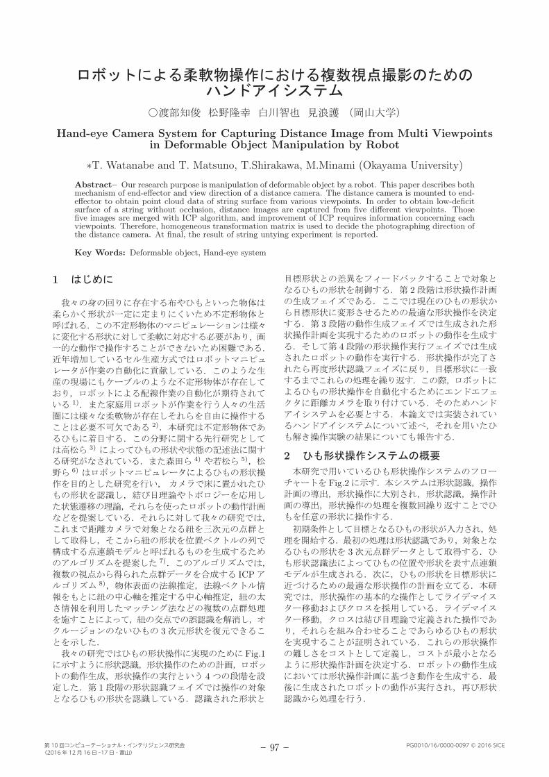
Fig. 5:
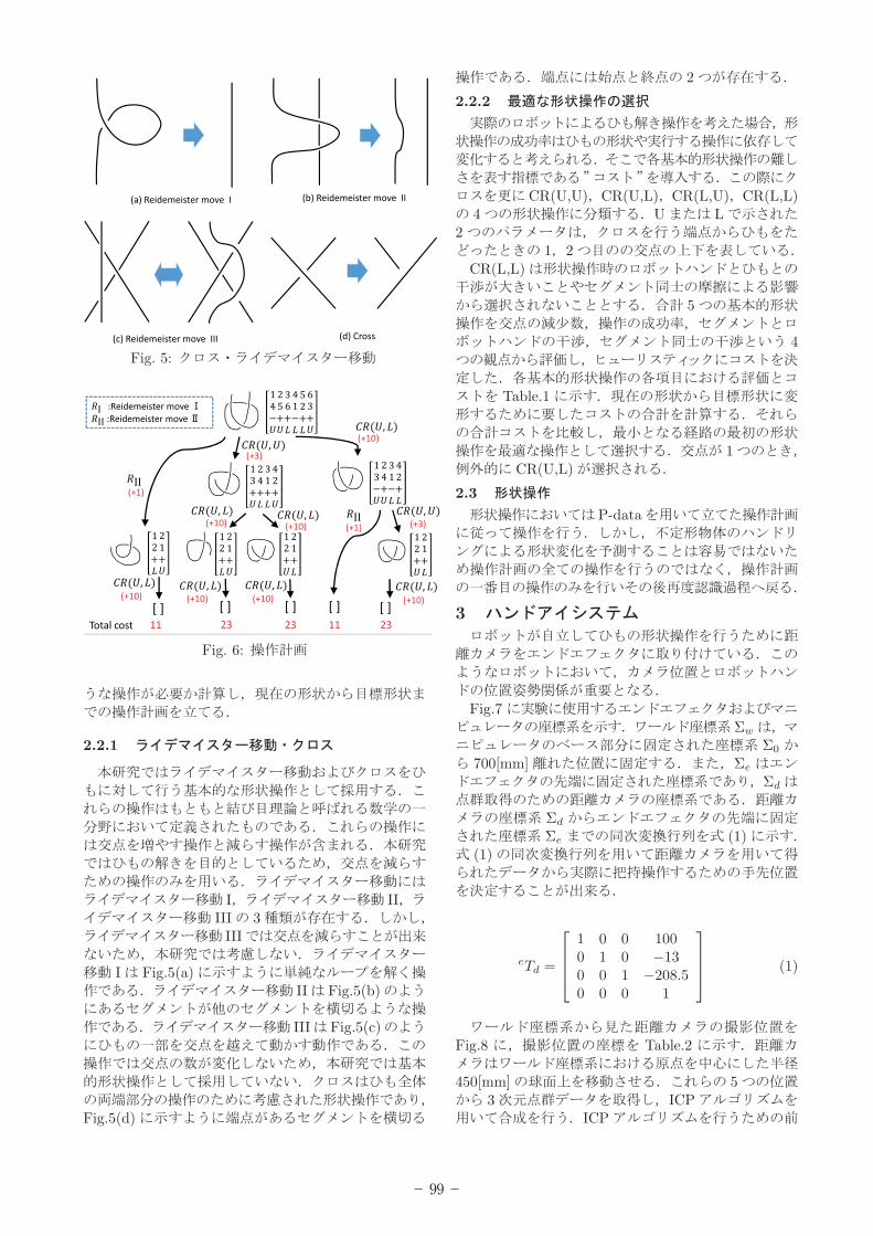
Fig. 6:
2.2.1
I IIIII 3
III
I Fig.5(a)II Fig.5(b)
III Fig.5(c)
Fig.5(d)
2
2.2.2
CR(U,U) CR(U,L) CR(L,U) CR(L,L)4 U L
21 2
CR(L,L)
5
4
Table.1
1CR(U,L)
2.3
P-data
3
Fig.7Σw
Σ0
700[mm] Σe
Σd
Σd
Σe (1)(1)
eTd =
1 0 0 1000 1 0 −130 0 1 −208.50 0 0 1
(1)
Fig.8 Table.2
450[mm] 53 ICP
ICP

- 100 -
Table 1: The evaluation and cost of shape operations
Viewpoint RM I RM II CR(U,U) CR(U,L) CR(L,U)
Decline of nodes fair good fair fair fair
Success rate fair fair good fair good
Interference between segments fair good good fair fair
Interference between segments and the robot’s hand fair good good bad good
Cost 8 1 3 10 5
Fig. 7:
(2) (6) 53
Table 2:x[mm] y[mm] z[mm]
V1 0 0 450
V2 116.46 0 434.67
V3 -116.46 0 434.67
V4 0 -116.46 434.67
V5 0 116.46 434.67
wTV 1 =
0 0 1 00 1 0 0−1 0 0 4500 0 0 1
(2)
wTV 2 =
−0.259 0 0.966 −116.470 1 0 0
−0.966 0 −0.259 434.670 0 0 1
(3)
Fig. 8:
wTV 3 =
0.259 0 0.966 116.470 1 0 0
−0.966 0 0.259 434.670 0 0 1
(4)
wTV 4 =
0 0 1 00.259 0.966 0 −116.47−0.966 0.259 0 434.67
0 0 0 1
(5)
wTV 5 =
0 0 1 0−0.259 0.966 0 116.47−0.966 −0.259 0 434.67
0 0 0 1
(6)
3.1 ICP
1
3ICP(Iterative Closest Point)
1 ICP
- 101 -
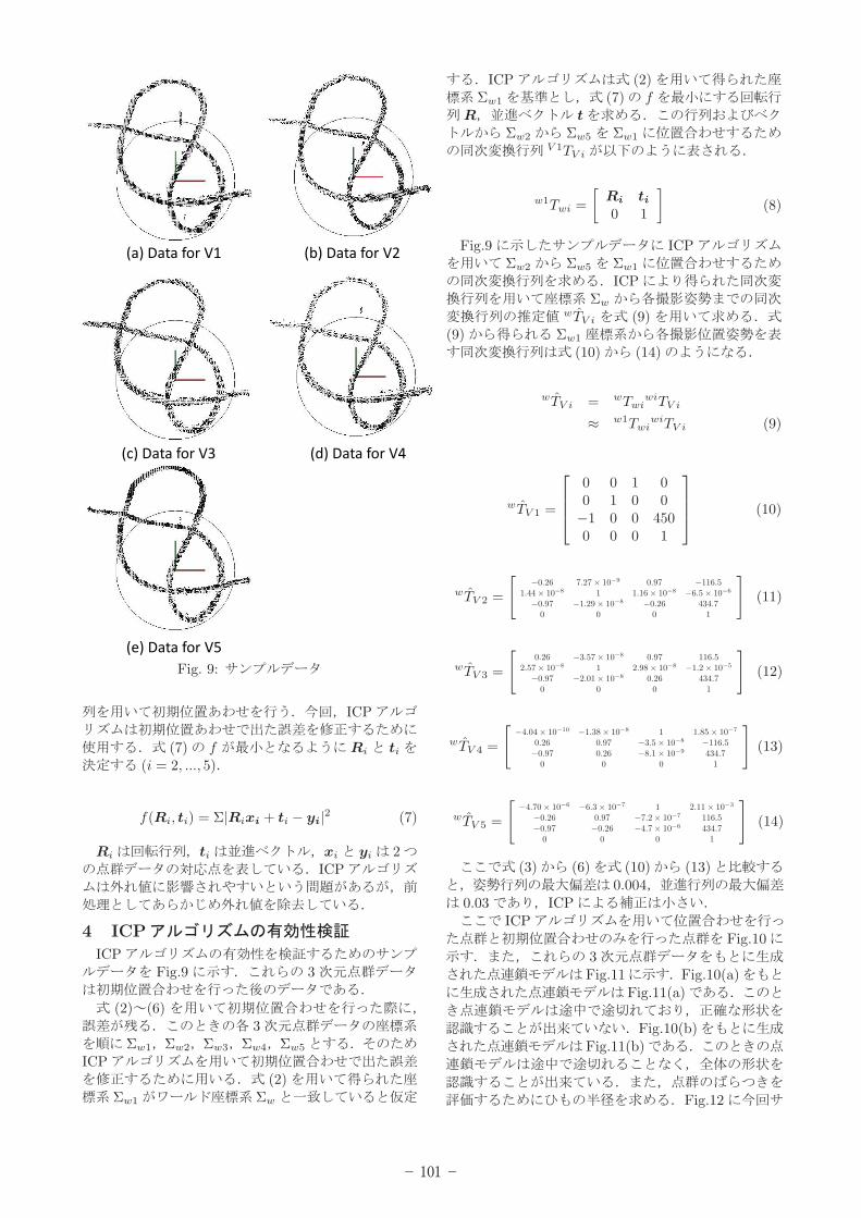
Fig. 9:
ICP
(7) f Ri ti
(i = 2, ..., 5)
f(Ri, ti) = Σ|Rixi + ti − yi|2 (7)
Ri ti xi yi 2ICP
4 ICP
ICPFig.9 3
(2) (6)3
Σw1 Σw2 Σw3 Σw4 Σw5
ICP(2)
Σw1 Σw
ICP (2)Σw1 (7) f
R t
Σw2 Σw5 Σw1
V 1TV i
w1Twi =
[
Ri ti
0 1
]
(8)
Fig.9 ICPΣw2 Σw5 Σw1
ICPΣw
wT̂V i (9)(9) Σw1
(10) (14)
wT̂V i = wTwiwiTV i
≈ w1TwiwiTV i (9)
wT̂V 1 =
0 0 1 00 1 0 0−1 0 0 4500 0 0 1
(10)
wT̂V 2 =
[
−0.26 7.27 × 10⁻⁹ 0.97 −116.51.44 × 10−8 1 1.16 × 10⁻⁸ −6.5 × 10⁻⁶
−0.97 −1.29 × 10⁻⁸ −0.26 434.70 0 0 1
]
(11)
wT̂V 3 =
[
0.26 −3.57 × 10⁻⁸ 0.97 116.52.57 × 10−8 1 2.98 × 10⁻⁸ −1.2 × 10⁻⁵
−0.97 −2.01 × 10⁻⁸ 0.26 434.70 0 0 1
]
(12)
wT̂V 4 =
[
−4.04 × 10⁻¹⁰ −1.38 × 10⁻⁸ 1 1.85 × 10⁻⁷
0.26 0.97 −3.5 × 10⁻⁸ −116.5−0.97 0.26 −8.1 × 10⁻⁹ 434.7
0 0 0 1
]
(13)
wT̂V 5 =
[
−4.70 × 10⁻⁶ −6.3 × 10⁻⁷ 1 2.11 × 10⁻³
−0.26 0.97 −7.2 × 10⁻⁷ 116.5−0.97 −0.26 −4.7 × 10⁻⁶ 434.7
0 0 0 1
]
(14)
(3) (6) (10) (13)0.004
0.03 ICPICP
Fig.103Fig.11 Fig.10(a)
Fig.11(a)
Fig.10(b)Fig.11(b)
Fig.12

- 102 -
Fig. 10:
Fig. 11:
Fig.12 Fig.10(a),(b)
Table3 10 9ICP ICP
ICP
Fig. 12:
Table 3:maximum radius[mm]
Point ICP without ICP
No.1 6.27 8.39
No.2 7.52 8.38
No.3 6.39 7.10
No.4 6.60 9.43
No.5 5.53 8.86
No.6 8.69 8.83
No.7 8.96 8.54
No.8 5.44 7.44
No.9 5.77 8.14
No.10 6.32 8.24
6.75 8.34
0.00125 0.00068
Fig. 13:
5
0P-dataFig.13
1[m] 8.4[mm]
5.1
Fig.14 Fig.14(a)5
Fig.14(b)P-data
P-data P-data
P-data
Fig.14(c)Fig.14(d)
5.2
5.2.1 1
Fig.13(a)Fig.15
Fig.16

- 103 -
Fig. 14:
Fig.15(a)Fig.15(e)
CR(U,L)
Fig.15(b) 2
Fig.15(f)CR(L U)
Fig.15(c)
Fig.15(g)1
CR(U,L) Fig.15(h)0
5.2.2 2
Fig.13(b)Fig.17 Fig.17(a)
Fig.17(e) CR(L,U)Fig.17(b)
Fig.17(f)CR(U,L)
Fig.17(c)Fig.17(g)
1 CR(U,L)Fig.17(h)
02
6
Fig. 15: 1
Fig. 16: 1-1
5

- 104 -
Fig. 17: 2
MEXT JP26820088
1) ,, ,Vol.27, No.10,
pp1082-pp1085,Jul.2009.
2)-
-135-2 2002
3)
Vol.23No.5 pp.572 582, 2005.
4)
135-12 2002.
5) /
Vol.23 No.3 pp.344 351 2005.
6)
Vol.41, No.4, p.366 p.372 2005
7) Keisuke Mukai Takayuki Matsuno Akira YanouMamoru Minami Shape Modeling of A String AndRecognition Using Distance Sensor IEEE 24th In-ternational Symposium on Robot and Human Inter-active Communication Aug.31-Sep.4 2015.
8)2012.


![{U` w FBSUGVM PNNVOJDBUJPO...+"{U` wÔ Ô y R å Sw 8 Ä pxz ö O sw æ~ Y !Z×z~~µw è ªpK H öÀ w t ÿ GIH öÀ \ w GIH ¬wÆ Q=Iwî «t²Zz Êù»~] b ; w ^ w è ¢t qlhÄÀ](https://static.documents.pub/doc/80x56/5ec416fee2fbf52ed91cd7b6/u-w-fbsugvm-pnnvojdbujpo-u-w-y-r-sw-8-pxz-o-sw-.jpg)
