
14th Feb. 2001Page 1
LISA Mission Review
PresentationESTEC, 14th Feb.
2001
Prepared by the CDF* Team(*) ESTEC Concurrent Design Facility
LISA Mission Review
14th Feb. 2001Page 2
LISA Mission Review
LISA Mission StatusAgenda
• Objectives of review• Mission overview• Technical requirements• Baseline design• Simulation• Results from study review (i.e. design issues)
• Recommendation for future activities• design/verification upgrade• detailed AIT/AIV approach
14th Feb. 2001Page 3
LISA Mission Review
LISA Study Review Objectives
- Review of LISA industrial study- Ref.: Final Technical Report, astrium, LI-RP-DS-0009- Review performed in ESTEC Concurrent Design
Facility (CDF) using existing CDF models
- Objectives- Review of proposed spacecraft and s/s design w.r.t.
- consistency, completeness and maturity of the design- identification of critical issues- building of CDF model with data from industrial study- building of CATIA model
- Bringing ESA technical staff up to date - Preparation of the plan for further activities
14th Feb. 2001Page 4
LISA Mission Review
LISA Mission Overview (1/3)
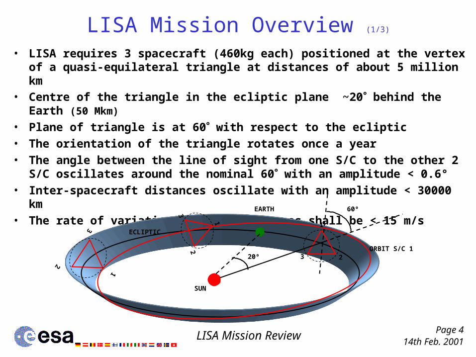
• LISA requires 3 spacecraft (460kg each) positioned at the vertex of a quasi-equilateral triangle at distances of about 5 million km
• Centre of the triangle in the ecliptic plane ~20 behind the Earth (50 Mkm)
• Plane of triangle is at 60 with respect to the ecliptic• The orientation of the triangle rotates once a year• The angle between the line of sight from one S/C to the other 2 S/C
oscillates around the nominal 60 with an amplitude < 0.6° • Inter-spacecraft distances oscillate with an amplitude < 30000 km • The rate of variation of these distances shall be < 15 m/s
1
231
2
3
1
2
3
SUN
EARTH 60º
ORBIT S/C 120º
ECLIPTIC

14th Feb. 2001Page 5
LISA Mission Review
LISA Mission Overview (2/3)
S/M >>>P/M >>>
figure taken from
LI-RP
-DS
-009
S/M >>>P/M >>>
• The stack of 3 LISA spacecraft shall be launched by a single Delta II 7925H three stage launcher (3x800mm)
• Each S/C (science module, S/M) is attached to a 203mmhigh Propulsion Module (P/M) with electrical propulsion (independent transfer to operational orbit)
• Lifetime 2 years on station (ext.10 yrs) plus < 15 months transfer (difference of 1 - 2 months between S/C)
• After cruise phase P/M is jettisoned• The LISA spacecraft will separate one
by one, and perform autonomously any required attitude manoeuvre.
• In science mode the S/C are controlled using the FEEPs to achieve drag-free mode. Only the gravitational forces of
the Sun, planets, and other bodies determine the trajectory of each S/C
S/M >>>P/M >>>
14th Feb. 2001Page 6
LISA Mission Review
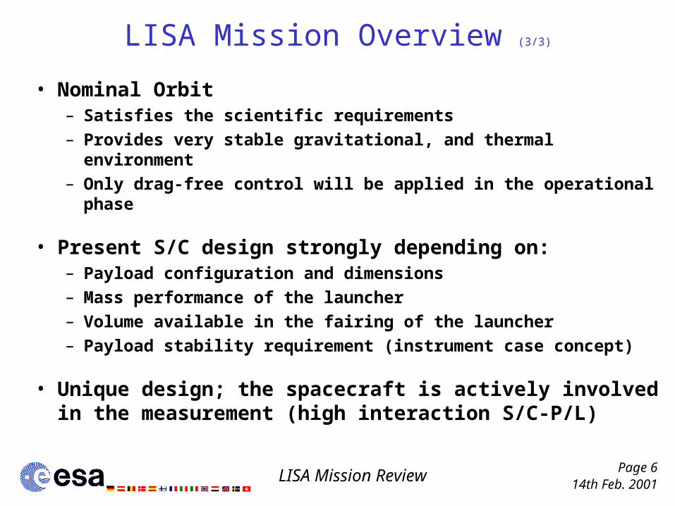
LISA Mission Overview (3/3)
• Nominal Orbit– Satisfies the scientific requirements– Provides very stable gravitational, and thermal environment– Only drag-free control will be applied in the operational phase
• Present S/C design strongly depending on:– Payload configuration and dimensions– Mass performance of the launcher– Volume available in the fairing of the launcher– Payload stability requirement (instrument case concept)
• Unique design; the spacecraft is actively involved in the measurement (high interaction S/C-P/L)
14th Feb. 2001Page 7
LISA Mission Review
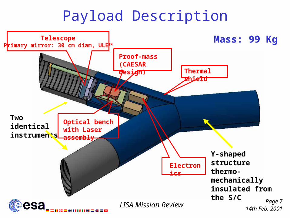
Payload Description
Y-shaped structure thermo-mechanically insulated from the S/C
Two identical instruments
Optical bench with Laser assembly
Proof-mass (CAESAR design)
Electronics
TelescopePrimary mirror: 30 cm diam, ULETM
Thermal shield
Mass: 99 Kg
14th Feb. 2001Page 8
LISA Mission Review
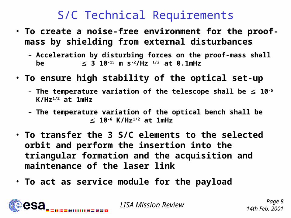
S/C Technical Requirements• To create a noise-free environment for the proof-mass
by shielding from external disturbances
– Acceleration by disturbing forces on the proof-mass shall be 3 10-15 m s-2/Hz 1/2 at 0.1mHz
• To ensure high stability of the optical set-up
– The temperature variation of the telescope shall be 10-5 K/Hz1/2 at 1mHz
– The temperature variation of the optical bench shall be 10-6 K/Hz1/2 at 1mHz
• To transfer the 3 S/C elements to the selected orbit and perform the insertion into the triangular formation and the acquisition and maintenance of the laser link
• To act as service module for the payload
14th Feb. 2001Page 9
LISA Mission Review
0.2
m
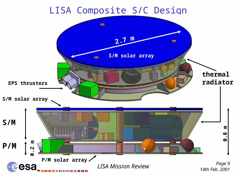
LISA Composite S/C Design
S/M solar array
S/M
0.8
m
P/M solar array
S/M solar array
2.7 m
EPS thrusters
P/M
thermal radiator

14th Feb. 2001Page 10
LISA Mission Review
Science Module Design
solar array(multi junction cells)
shear walls (isostatic interface between
the module service unit and the payload )
tubes (load transfer during launch)
thermal radiator
Mass: 288 Kg (with 5% margin)Power: 284 W (average)
FEEP’s
HGA’s
14th Feb. 2001Page 11
LISA Mission Review
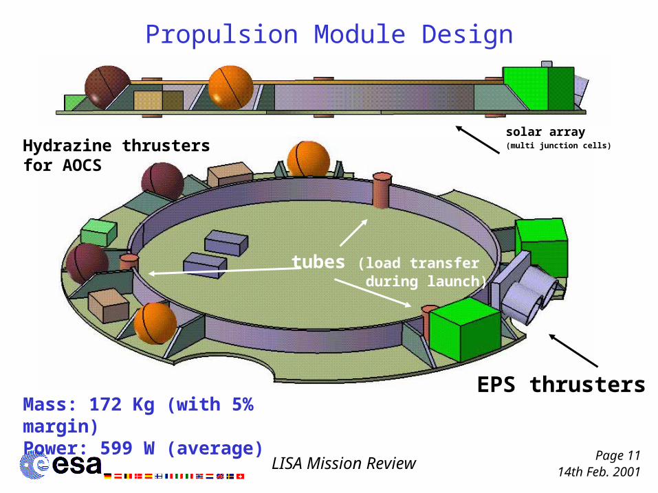
Propulsion Module Design
solar array(multi junction cells)
EPS thrusters
tubes (load transfer during launch)
Mass: 172 Kg (with 5% margin)Power: 599 W (average)
Hydrazine thrusters for AOCS

14th Feb. 2001Page 12
LISA Mission Review
Interfaces
launcher
P/M
support unit structure
electrical / structural interface
electrical / structural (isostatic) interface
optical units
proof mass
AOCS incl. FEEP’s
other subsystems
Payload
OBDH
Basic building blocks
S/M
electrical / mech
anic
al interface

14th Feb. 2001Page 13
LISA Mission Review
LISA Study Review Summary
The review team found:
– Five major system design issues– Several minor design issues at subsystem design level

14th Feb. 2001Page 14
LISA Mission Review
System Design Issues (1/7)
Mass budget marginal• Delta II allows only for 5% system margin • Estimated unit/subsystem masses optimistic (especially
Propulsion Module)
Mass budget per S/C (Kg) Total (Kg)
Total wet mass according to Industrial Study (with 5% margin) 458.70 1376.10Corrected Total wet mass (with 5% margin) * 472.70 1418.10Total wet mass with CDF system margin (20%) 536.90 1610.70
Delta II 7925H mass performance 1380.00Delta III mass performance 2670.00Atlas IIA mass performance 2230.00
* Summing up the subsystem masses (inconsistency with the total budget)
Soyuz Fregat mass performance 1390.00
14th Feb. 2001Page 15
LISA Mission Review
System Design Issues (2/7)
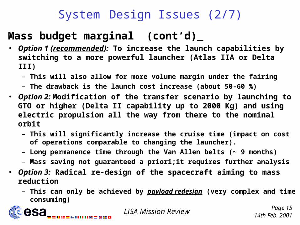
Mass budget marginal (cont’d) • Option 1 (recommended): To increase the launch capabilities by
switching to a more powerful launcher (Atlas IIA or Delta III)– This will also allow for more volume margin under the fairing
– The drawback is the launch cost increase (about 50-60 %)
• Option 2: Modification of the transfer scenario by launching to GTO or higher (Delta II capability up to 2000 Kg) and using electric propulsion all the way from there to the nominal orbit– This will significantly increase the cruise time (impact on cost of
operations comparable to changing the launcher).
– Long permanence time through the Van Allen belts (~ 9 months)
– Mass saving not guaranteed a priori;it requires further analysis
• Option 3: Radical re-design of the spacecraft aiming to mass reduction– This can only be achieved by payload redesign (very complex and time
consuming)

14th Feb. 2001Page 16
LISA Mission Review
System Design Issues (3/7)
Spacecraft configuration extremely streamlined• Volume available under Delta II fairing very constraining (max
height: 2.40 m, max diam. 2.75 m) for composite S/C COG position constraint
• Propulsion Module only 0.2 m high• Accommodation of some equipment questionable (e.g. PCU,
FEEP’s)
Recommended solution:
To go for a launcher with larger fairing volume
The other possible options are: – Redesign of the spacecraft implying significant changes in the
payload design– Re-examine the possibility of one single Propulsion Module for all 3
spacecraft (big impact on cruise complexity)
14th Feb. 2001Page 17
LISA Mission Review
System Design Issues (4/7)
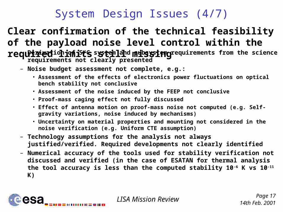
– Derivation of S/C system and subsystem requirements from the science requirements not clearly presented
– Noise budget assessment not complete, e.g.:• Assessment of the effects of electronics power fluctuations on optical bench
stability not conclusive• Assessment of the noise induced by the FEEP not conclusive• Proof-mass caging effect not fully discussed • Effect of antenna motion on proof-mass noise not computed (e.g. Self-gravity
variations, noise induced by mechanisms)• Uncertainty on material properties and mounting not considered in the noise
verification (e.g. Uniform CTE assumption)
– Technology assumptions for the analysis not always justified/verified. Required developments not clearly identified
– Numerical accuracy of the tools used for stability verification not discussed and verified (in the case of ESATAN for thermal analysis the tool accuracy is less than the computed stability 10-6 K vs 10-11 K)
Clear confirmation of the technical feasibility of the payload noise level control within the required limits still missing
14th Feb. 2001Page 18
LISA Mission Review
System Design Issues (5/7)
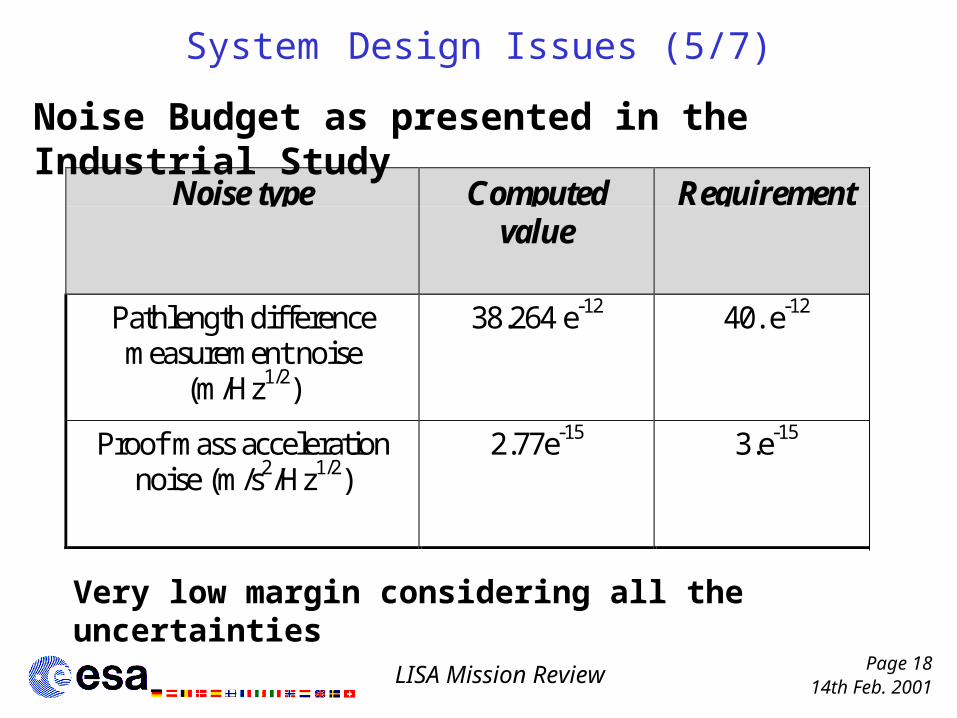
Noise type Computedvalue
Requirement
Pathlength differencemeasurement noise
(m/Hz1/2)
38.264 e-12 40. e-12
Proof mass accelerationnoise (m/s2/Hz1/2)
2.77e-15 3.e-15
Noise Budget as presented in the Industrial Study
Very low margin considering all the uncertainties

14th Feb. 2001Page 19
LISA Mission Review
System Design Issues (6/7)
Propulsion Module design incomplete • Thermal design missing - Issues expected• SA design marginal even considering the highest available
efficiency for the solar cells• Structures/configuration marginal
Sun on the high electronic dissipating units and on the S/M radiator
Sun direction
25o
Side facing deep space
Tanks may run very cold
Thermal issue during Cruise - schematic
14th Feb. 2001Page 20
LISA Mission Review
System Design Issues (7/7)
– International co-operation aspects not fully addressed by the contractor
– Verification/Testing of the effects of the spacecraft on the payload performance not sufficiently addressed (special instrumentation and test methods not discussed, modelisation not described)
– Integration issue not addressed in the configuration design
Integration and Test Issues (AIT/AIV)

14th Feb. 2001Page 21
LISA Mission Review
Main Conclusions (1/2)
• The contractor made a significant effort to fulfil the science-driven requirements within the very tight launcher mass and volume constraints
• The nominal operational orbit and the constellation configuration selected satisfy mission requirements
• The payload design has received much attention and is well advanced
However

14th Feb. 2001Page 22
LISA Mission Review
Main Conclusions (2/2)• The Delta II capability is not adequate for the mission
and it is strongly suggested to use a more powerful launcher
• Feasibility of noise control methods is not fully convincing due to fragmented analysis ( i.e. elements addressed but total picture not presented)– The assessment of the noise induced by the spacecraft is incomplete
and not thoroughly discussed
– For a proper noise budget calculation there is a need to assess which kind of tools are needed and which numerical requirements must be fulfilled
– With each noise source identified there should be a clear definition how it is tested or analytically verified
• In same areas (e.g. P/M) the design is at low level of detail

14th Feb. 2001Page 23
LISA Mission Review
Example of Design Issues at Subsystem Level (1/2)
AOCS design– approach seems sound but a comprehensive drag free control simulation
is missing
– Verification of the assumed hardware performance vs technology availability not fully convincing (clear requirements for technology development missing)
Mechanisms– Design schematic, not all the required mechanisms clearly
identified/selected
Power– Potential contamination from the propulsion units on the SA of the PM not
addressed
– Power margin applied generally low
– Electro-magnetic noise from power components not addressed
14th Feb. 2001Page 24
LISA Mission Review
Example of Design Issues at Subsystem Level (2/2)
TT&C– Design schematic (link budgets not detailed, trade-offs not
justified)
Data Handling– Little attention paid to S/W development and integration with
payload software

14th Feb. 2001Page 25
LISA Mission Review
Areas Requiring More Detailed Work (1/2)
Mass budget marginal – Investigation of more powerful launchers: Atlas IIA or Delta III– Further mission trade-offs
Propulsion Module design– Thermal, Power and Configuration issues to be addressed
Noise budget– Re-assessment of the disturbance effects from the SM on the
payload performance
Thermal Design of SM and PM– Verification of the transfer phase & stability during the nominal
operations
14th Feb. 2001Page 26
LISA Mission Review
Areas Requiring More Detailed Work (2/2)
AOCS subsystem performance verification– Achievable accuracy performance of the hardware to be
verified– More accurate dynamical model of the Control System to be
built
AIT/AIV approach to be addressed in detail


