

State Key Lab. of ISN, Xidian University
3. Channel Propagation, Fading, and Link Budget Analysis
3.1 Introduction
3.2 Radio Wave Propagation
3.3 Large-Scale Fading or Macroscopic Fading
3.4 Small-Scale Fading
3.5 Microscopic Fading Measurements
3.6 Antenna Diversity
Reference

State Key Lab. of ISN, Xidian University
3.1 Introduction
In Chapter 2 we examined the mutual information capacity of
wireless communication based on MIMO channels. We found that
this capacity grows linearly with the number of antennas in flat
fading channels, due to the increase in the number of spatial data
pipes. All this is accomplished without increasing the bandwidth or
power.
In this chapter, we examine channel fading and propagation
issues. We will also discuss a few channel propagation models
and carry out link budget analysis. Finally we examine certain
diversity combing techniques like selection diversity, maximal ratio
combining, and equal gain combining.

State Key Lab. of ISN, Xidian University
3.2 Radio Wave Propagation
3.2.1 Reflection
3.2.2 Diffraction
3.3.3 Scattering

State Key Lab. of ISN, Xidian University
The mobile radio channel experiences a lot of
limitations on the performance of wireless systems.
The modeling is based more on statistics and requires
specific measurements for an intended communication
system.
Broadly the mechanics of electromagnetic wave
propagation are confined to reflection, diffraction, and
scattering.
– Reflection, diffraction, and scattering are the three basic
propagation mechanisms for radio waves. Received power (or
its reciprocal, path loss) is generally the most important
parameter predicted by large-scale propagation models and is
based on these three phenomena. This is also applicable to
small-scale fading and multipath propagation.

State Key Lab. of ISN, Xidian University
3.2.1 Reflection
This occurs when electromagnetic waves bounce off objects whose dimensions are compared with the wavelength of the propagating wave.
The electric field intensity of the reflected and transmitted waves may be related to the incident wave in the medium of origin through the Fresnel reflection coefficient. This reflection coefficient is a function of the material properties and generally depends on the wave polarization, angle of incidence, and frequency of the propagating wave.

State Key Lab. of ISN, Xidian University
3.2.2 Diffraction
Diffraction allows radio signals to propagate around the curved surface of the earth, beyond the horizon, and behind obstructions.
The phenomenon of diffraction can be explained by the Huygens principle, which states that all points on a wavefront can be considered as point sources for the production of secondary wavelets and that these secondary wavelets combine to produce a new wavefront in the direction of propagation.

State Key Lab. of ISN, Xidian University
3.3.3 Scattering
The actual received signal in a mobile radio
environment is often stronger than what is predicted by
reflection and diffraction models alone. This occurs
because when a radio wave impinges on a rough
surface, the reflected energy is spread out (diffused) in
all directions due to scattering.
Sometimes reflection, diffraction and scattering are
collectively referred to as scattering.

State Key Lab. of ISN, Xidian University
Cellular systems usually operate in urban areas, where there is no direct line-of-sight path between the transmitter and receiver and where high-rise buildings cause severe diffraction loss. Multiple reflections from various objects cause the electromagnetic waves to travel along different paths of varying lengths. The interaction between these waves causes multipath fading at a given location, because their phases are such that sometimes they add and sometimes they subtract (fade). The strengths of these waves slowly reduce with distance from the transmitter.

State Key Lab. of ISN, Xidian University
Propagation models based on average-received signal
strength at a given distance from the transmitter are
useful to estimate a radio coverage area and are called
large-scale propagation models or macroscopic fading
models. They are characterized by a large separation –
usually a few kilometers – between the transmitter and
receiver.
– Large-scale fading is manifest when the mobile moves over
larger distances, causing the local average signal level to
gradually decrease. Typically, the local average-received
power is measured by averaging signal measurements over a
measurement track of 5λ to 40λ. For cellular frequencies in the
1 to 2 GHz band, this works out to movements of 1 to 10 m.

State Key Lab. of ISN, Xidian University
Propagation models that characterize the rapid
fluctuations of the receive signal strength over very
short distances (a few wavelengths) or short time
durations (on the order of seconds) are called small-
scale propagation models or microscopic fading
models. They give rise to rapid fluctuations as the
mobile moves over short distances and the received
power sometimes varies as much as 30 to 40 dB when
the receiver moves only a fraction of a wavelength.
– Small-scale fading movements are rapid fluctuations, whereas
large-scale fading movements are much slower average
changes in signal strength. The statistical distribution of this
mean is influenced by parameters like frequency, antenna
heights, environments and so on.

State Key Lab. of ISN, Xidian University
Figure 3.1 Small-scale and large-scale fading

State Key Lab. of ISN, Xidian University
It is observed that the received power averaged over microscopic fading approaches a normal distribution when plotted on a logarithmic scale (i.e., in decibels) and is called log-normal distribution. It is given by
(3.1) – x is in decibels and is a random variable
representing the long-term signal power level fluctuation;
– μ and σ are, respectively, the mean and standard deviation of x expressed in decibels. μ is the path loss described earlier. A typical value for σ is 8 dB.
2
2
2
2
1
x
exf

State Key Lab. of ISN, Xidian University
3.3 Large-Scale Fading or Macroscopic Fading
3.3.1 Free-Space Propagation Model
3.3.2 Outdoor Propagation Models

State Key Lab. of ISN, Xidian University
3.3.1 Free-Space Propagation Model
If there is a clear unobstructed line-of-sight path
between the transmitter and receiver, then we resort to
the free-space propagation model. Satellite
communication systems and microwave line-of-sight
radio links undergo free-space propagation. In this
model, the power is presumed to decay with distance
from the transmitter according to some power law,
usually as square of the distance from the transmitter.

State Key Lab. of ISN, Xidian University
The free-space power received by an antenna
at a distance d from the transmitter is given by,
(3.2)
where Pt is the transmitted power, Pr(d) is the
received power as a function of the separation
distance d in meters, Gt is the transmit antenna
gain, Gr is the receive antenna gain, L is the
system loss not related to propagation (L ≥ 1)
and λ is the wavelength in meters.
Ld
GGPdP rtt
r 22
2
4

State Key Lab. of ISN, Xidian University
The gain of an antenna is related to its effective
aperture by
G = 4πAe/λ2 (3.3)
λ is related to the carrier frequency by
λ= c/f (3.4)
where f is the carrier frequency in Hz and c is the speed
of light in meters/sec (3x10⁸ m/sec).
The values of Pt and Pr must be expressed in identical
units and Gt and Gr are dimensionless quantities. The
miscellaneous losses are usually due to transmission
line attenuation (plumbing losses), filter losses, and
antenna losses in the communication system.

State Key Lab. of ISN, Xidian University
Equation (3.2) shows that the received power
falls off as the square of the separation
distance d. This implies that the received
power decays with distance at a rate of 20
dB/decade.

State Key Lab. of ISN, Xidian University
We define an isotropic radiator as an ideal antenna
that radiates power with unit gain uniformly in all
directions and is often used as a reference antenna
gain in wireless systems. The effective isotropic
radiated power (EIRP) is defined as
(3.5)
and represents the maximum radiated power available
from a transmitter in the direction of maximum antenna
gain compared with an isotropic radiator. In practice,
antenna gains are given in units of dBi (dB gain with
respect to an isotropic antenna).
ttGPEIRP

State Key Lab. of ISN, Xidian University
The path loss is defined as the difference (in dB)
between the transmitted power and the received power
and is given by
(3.6)
It is import to note that the free-space model is only
applicable in the so-called far-field region of the
transmitted antenna or in the Fraunbofer region and is
defined as
(3.7)
where D is the larger physical linear dimension of the
antenna.
Ld
GG
P
PdBPL rt
r
t
22
2
4log10log10)(
22Dd
f

State Key Lab. of ISN, Xidian University
Large-scale propagation models use a close-in
distance, d0, as a known received power reference
point. The received power at any distance d>d0 may
then be related to Pr and d0. The value Pr(d0) may be
predicted from (3.2) by extrapolation or may be
measured in the radio environment by taking the
average received power at many points located at a
close-in radial distance d0 from the transmitter. The
reference distance must be so chosen that it lies in the
far-field and d0 is chosen to be smaller than any
practical distance used in the mobile communication
system. Thus from (3.2), the received power in free
space at a distance greater than d0 is given by
(3.8) frr
dddd
ddPdP
0
2
0
0

State Key Lab. of ISN, Xidian University
In mobile radio systems, Pr changes by many orders of magnitude over a typical coverage area of several square kilometers. In view of the very large dynamic range of received power levels, dBm and dBW units are used to express received power levels. dBm is the power in dBs referred to one milliwatt. dBW is the power in dBs referred to one watt. For example,
(3.9)
where Pr(d0) is in watts.
The reference distance d0 for practical systems using low-gain antennas in the 1-2 GHz region is typically 1m in indoor environments and 100 m or 1 Km in outdoor environments, so that the numerator in (3.8) and (3.9) is a multiple of 10.
f
r
rddd
d
d
W
dPdP
0
2
00 log20001.0
log10(dBm)

State Key Lab. of ISN, Xidian University
Example 1 and 2
Find the far-field distance for an antenna with
maximum dimension of 2m and operating frequency of
900 MHz.
If a transmitter produces 50W of power, express the
transmit power in units of (a) dBm and (b) dBW. If 50W
is applied to an antenna of gain 1, find the received
power in dBm at a free-space distance of 100m from
the antenna. What is Pr (10 km)? Assume a gain of 2
for the receiver antenna and no system losses.

State Key Lab. of ISN, Xidian University
3.3.2 Outdoor Propagation Models
3.3.2.1 Okumura Model
3.3.2.2 Hata Model

State Key Lab. of ISN, Xidian University
Free-space propagation is rarely encountered in real-
life situations. In reality, we need to take into account
the terrain profile in a particular area for estimating
path loss. A number of propagation models are
available to predict path loss over irregular terrain.
These models differ in their ability to predict signal
strength at a particular receiving point or in a specific
local area (called a sector) because their approach is
different and their results vary in terms of accuracy and
complexity. These models are based on iterative
experiments conducted over a period of time by
measuring data in a specific area.

State Key Lab. of ISN, Xidian University
3.3.2.1 Okumura Model
Okumura developed a set of curves giving the median attenuation relative to free space (Amu) in an urban area over a quasi-smooth terrain with a base station effective antenna height (hte) of 200m and a mobile antenna height (hre) of 3m. These curves were developed from extensive measurements using vertical omni-directional antennas at both base and mobile and are plotted as a function of frequency in the range of 100 to 1920 MHz and as a function of distance from the base station in the range of 1 to 100 Km.

State Key Lab. of ISN, Xidian University
To use these curves, we first determine the free-space
path loss between the points of interest and then the
value of Amu(f,d) (as read from the curves) is added to
it along with correction factors to account for the type of
terrain. The model is expressed as
(3.10)
where L50 is the 50th percentile value of propagation path
loss, LF is the free-space propagation loss, G(the) is the
base station antenna height gain factor, G(hre) is the
mobile antenna height fain factor, and GAREA is the gain
due to the type of environment. The antenna height
gains are strictly a function of height and have nothing
to do with the antenna patterns.
AREAretemuF
GhGhGdfALL ,dB 50

State Key Lab. of ISN, Xidian University
Figure 3.2 Median attenuation relative to free space (Amu(f, d)) over a quasi-smooth terrain

State Key Lab. of ISN, Xidian University
Figure 3.3 Correction factor GAREA for different types of terrain

State Key Lab. of ISN, Xidian University
Okumura determined that G(hte) varies at a
rate of 20 dB/decade and G(hre) varies at a
rate of 10 dB/decade for heights of less than
3m.
(3.11)
(3.12)
(3.13)
mhmh
hGte
te
te301000
200log20
mhh
hGre
re
re3
3log10
mhmh
hGre
re
re310
3log20

State Key Lab. of ISN, Xidian University
Other corrections may also be applied to Okumura’s model. Some of these are terrain undulation height (Δh), isolated ridge height, average slope of the terrain, and the mixed land-sea parameter. Once the terrain-related parameters are calculated, the necessary correction factors can added or subtracted as required. All these correction factors are also available as Okumura curves.
Okumura’s model is completely based on measured data and there is no analysis to justify it. All extrapolations to these curves for other conditions are highly subjective. Yet it is considered the simplest and best in terms of accuracy in path loss prediction for cellular systems in a cluttered environment. The major disadvantage is its low response to rapid changes in terrain. Hence, it is not so good in rural areas.

State Key Lab. of ISN, Xidian University
Example 3
Find the median path loss using Okumura’s
model for d = 50 Km, hte = 100m, hre = 10m in
a suburban environment. If the base station
transmitter radiates an EIRP of 1 kW at a
carrier frequency of 900 MHz, find the power at
the receiver (assume a gain of 2 at the
receiving antenna).

State Key Lab. of ISN, Xidian University
3.3.2.2 Hata Model
The Hata model is an empirical formulation of
the graphical path loss data provided by
Okumura and is valid from 150 to 1500 MHz.
Hata presented the loss as a standard formula
and supplied correction equations for
application to other situations.

State Key Lab. of ISN, Xidian University
The standard formula for median path loss in urban
areas is given by
(3.14)
where fc is the frequency in MHz from 150 to 1500 MHz,
hte is the effective transmitter (base station) antenna
height (in meters) ranging from 30 to 200m, hre is the
effective receiver (mobile) antenna height (in meters)
ranging from 1 to 10m, d is the T-R separation distance
(in Km), and a(hte) is the correction factor for effective
mobile antenna height, which is a function of the size
of the coverage area.
dhhahfdBurbanLteretec
loglog55.69.44log82.13log16.2655.69 50

State Key Lab. of ISN, Xidian University
For a small to medium-sized city, the correction
factor is given by
(3.15)
and for a large city,
(3.16)
(3.17)
dBfhfhacrecre
8.0log56.17.0log1.1
MHzfdBhhacrere
300 1.154.1log29.82
MHzfdBhhacrere
300 97.475.11log2.32

State Key Lab. of ISN, Xidian University
To obtain the path loss in a suburban area, the standard Hata formula in (3.13) is modified as
(3.18)
and for path loss in open rural areas, the formula is modified as
(3.19)
The predictions of Hata’s model compare very closely with the original Okumura model, if d exceeds 1 Km. This model is well-suited to large cell mobile systems.
This concludes our discussions on outdoor propagation models.
4.528log2 2
5050
cfurbanLdBL
94.40log33.18log78.4 2
5050
ccffurbanLdBL

State Key Lab. of ISN, Xidian University
3.4 Small-Scale Fading
Small-scale fading or simply fading is used to
describe the rapid fluctuations of the amplitude,
phases, or multipath delays of a radio signal
over a short period of time or travel distance,
so that large-scale path loss effects may be
ignored. Fading is caused by multipath waves.

State Key Lab. of ISN, Xidian University
Multipath in a radio channel creates small-
scale fading effects. These effects are
commonly characterized as causing:
– Rapid changes in signal strength over a small travel
distance or time interval.
– Random frequency modulation due to varying
Doppler shifts on different multipaths.
– Time dispersion (echoes) caused by multipath
propagation delays.

State Key Lab. of ISN, Xidian University
3.4.1 Microscopic Fading
3.4.1.1 Doppler Spread-Time Selective Fading
3.4.1.2 Delay Spread-Frequency Selective
Fading
3.4.1.3 Rician K-Factor Measurement
3.4.1.4 Angle Spread-Space Selective Fading

State Key Lab. of ISN, Xidian University
Microscopic fading refers to the rapid
fluctuations of the received signal in space,
time and frequency and is caused by the signal
scattering off objects between the transmitter
and receiver.
Since this fading is a superposition of a large
number of independent scattered components,
then by the central limit theorem, the
components of the received signal can be
assumed to be independent zero mean
Gaussian processes.

State Key Lab. of ISN, Xidian University
The envelope of the received signal is
consequently Rayleigh distributed and is given
by
(3.20)
– Ω is the average power.
– u(x) is the unit step function defined as
(3.21)
xuexfx
2
2
00
01
x
xxu

State Key Lab. of ISN, Xidian University
If there is a direct LOS path between the transmitter and receiver, the signal envelope is no longer Rayleigh and the distribution of the signal is Ricean. The Ricean distribution is often defined in terms of the Ricean factor, K, which is the ratio of the power in the mean component of the channel to the power in the scattered component.

State Key Lab. of ISN, Xidian University
The Ricean PDF of the envelope is given by
(3.22)
where I0 is the zero-order modified Bessel function of the first kind defined as
(3.23) – In the absence of a direct path, K=0 and the Ricean
PDF reduces to Rayleigh PDF, since I0(0)=1.
xuKK
xIeK
xfK
K
1
212
0
1 2
2
0
cos
0
2
1dexI x

State Key Lab. of ISN, Xidian University
Figure 3.4 Signal power fluctuation versus range in wireless channels

State Key Lab. of ISN, Xidian University
Figure 3.4 shows the combined effects of path
loss and macroscopic and microscopic fading
on received power in a wireless channel. We
note that the mean propagation loss increases
monotonically with range. Local deviations
from this mean occur due to macroscopic and
microscopic fading.
There are three types of microscopic fading:
– Doppler spread-time selective fading;
– Delay spread-frequency selective fading;
– Angle spread-space selective fading.

State Key Lab. of ISN, Xidian University
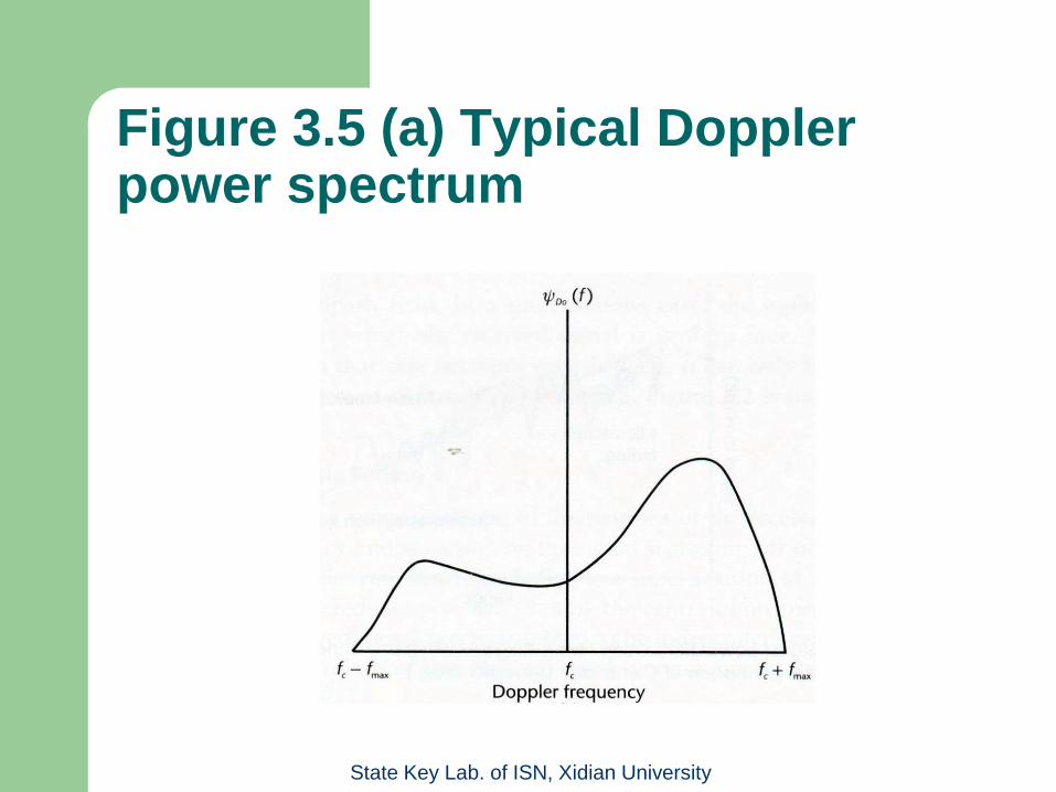
3.4.1.1 Doppler Spread-Time Selective Fading
Time varying fading due to the motion of a scatterer or
the motion of a transmitter or receiver or both results in
Doppler spread. The term spread in used to denote the
fact that a pure tone frequency fc in hertz spreads
across a finite bandwidth (fc±fmax). The Fourier
transform of the time autocorrelation of the channel
response to a continuous wave tone is defined as
Doppler power spectrum ψD0(f) with fc-fmax≤f≤ fc+fmax.
State Key Lab. of ISN, Xidian University
Figure 3.5 (a) Typical Doppler power spectrum

State Key Lab. of ISN, Xidian University
The Doppler power spectrum has a classical
U-shaped form and is approximated by Jakes
model.

State Key Lab. of ISN, Xidian University
The Doppler shift of the received signal
denoted by fd is given by
(3.24)
– v is the velocity of the moving object (or vehicle
speed, if we are talking about static scatterers and a
moving vehicle).
– θ is the relative angle between the moving object
and the point of reception of the Doppler signal.
Obviously, the maximum Doppler will be received at
a relative angle of 00 (i.e., when the moving object is
ahead or astern).
– c is the speed of light.
cosc
vff c
d

State Key Lab. of ISN, Xidian University
The root mean square bandwidth of ψD0(f) is called the
Doppler spread and is given by
(3.25)
where is the average frequency of the Doppler spectrum
and is given by
(3.26)
In LOS cases the spectrum is modified by an additional
discrete frequency component given by fd.
dff
dfffff
D
D
RMS
0
0
2
dff
dffff
D
D
0
0
f

State Key Lab. of ISN, Xidian University
We define coherence time of the channel as
(3.27)
where Tc is defined as the time lag for which the
signal autocorrelation coefficient reduces to 0.7.
– Tc serves as a measure of how fast the channel
changes in time, implying that the larger the
coherence time, the slower the channel fluctuation.
RMS
c
fT
1

State Key Lab. of ISN, Xidian University
Figure 3.5 (b) Fixed wireless Doppler spectra

State Key Lab. of ISN, Xidian University
The Doppler spectrum shown in Figure 3.5(a)
pertains to a mobile receiver moving at
constant speed. However, in a fixed wireless
channel, the receiver is static but there is
movement in the environment (e.g., trees and
foliage moving in a random manner due to
wind). In such cases, the Doppler spectrum is
as shown in Figure 3.5(b).

State Key Lab. of ISN, Xidian University
3.4.1.2 Delay Spread-Frequency Selective Fading
The small-scale variation of a mobile radio signal can be directly related to the impulse response of the mobile radio channel.
The impulse response is a useful characterization of the channel because it can be used to predict and compare the performance of many different mobile communication systems and transmission bandwidths for a particular channel condition.
To compare different multipath channels and develop some general design guidelines for wireless systems, certain parameters were decided on as benchmarks to quantify the multipath channel. These parameters are the mean excess delay, RMS delay spread, and excess delay spread and they can be determined from the power delay profile.

State Key Lab. of ISN, Xidian University
Figure 3.6 Example of an indoor power delay profile

State Key Lab. of ISN, Xidian University
Mean excess delay
The mean excess delay is the first moment of the
power delay profile and is defined as
(3.28)
kk
kkk
P
P

State Key Lab. of ISN, Xidian University
RMS delay spread
The RMS delay spread is the square root of the second central moment of the power delay profile and is defined as
(3.29)
where
(3.30) – These delays are measured relative to the first detectable
signal arriving at the receiver at τ0=0. Equations (3.28) to (3.30) do not rely on the absolute power level of P(τ), but only on the relative amplitudes of the multipath components within P(τ).
22
kk
kkk
P
P
2
2

State Key Lab. of ISN, Xidian University
Maximum delay spread (X dB)
The maximum excess delay is defined to be the time delay during
which multipath energy falls to X dB below the maximum. This
implies that maximum excess delay is defined as τx – τ0, where τ0
is the first arriving signal and τk is the maximum delay at which a
multipath component is within X dB of the strongest arriving
multipath signal ( which does not necessarily arrive at τ0).
The maximum excess delay tells us how long a multipath exists
above a given threshold. This value τk must be specified with a
threshold that relates the multipath noise floor to the maximum
received multipath component.

State Key Lab. of ISN, Xidian University
In practice, the values depends on the choice
of noise threshold used to process P(τ). The
noise threshold is used to differentiate between
received multipath components and thermal
noise.

State Key Lab. of ISN, Xidian University
Delay spread causes frequency selective fading as the channel acts like a tapped delay line filter. Frequency selective fading can be characterized in terms of coherence bandwidth, Bc, which is the frequency lag for which the channel’s autocorrelation function reduces to 0.7. We define coherence bandwidth as
(3.31)
When the coherence bandwidth is comparable with or less than the signal bandwidth, the channel is said to be frequency selective. Otherwise it is frequency flat or non-selective. A flat channel passes all spectral components with approximately equal gain and linear phase.
It is not possible to provide an exact relationship between coherence bandwidth and RMS delay spread, as it is a function of specific channel impulse response and applied signals.
1
cB

State Key Lab. of ISN, Xidian University
3.4.1.3 Rician K-Factor Measurement
There are many techniques to measure Rician
K-factor from the power profile. The moment-
method estimation of K-factor has found
popular appeal. The details are beyond the
scope of this book.

State Key Lab. of ISN, Xidian University
Example 4
Calculate the mean excess delay, RMS delay
spread, and maximum excess delay (10 dB) for
the multipath profile given in Figure 3.7.
Estimate the coherence bandwidth of the
channel.

State Key Lab. of ISN, Xidian University
Figure 3.7 Multipath profile for Example 4

State Key Lab. of ISN, Xidian University
3.4.1.4 Angle Spread-Space Selective Fading
Angle Spread at the receiver refers to the angle of
arrival (AOA) of the multipath components at the
receive antenna. Similarly, the angle of departure
(AOD) from the transmitter of the multipath that
reaches the receivers is called the angle spread at the
transmitter.

State Key Lab. of ISN, Xidian University
We denote AOA by θ and the rest of the analysis is as was done for delay spread, the only difference being that instead of τ we substitute θ.
RMS angle spread is given by
(3.32)
where
(3.33) – These angles are measured relative to the first detectable
signal arriving at the receiver at θ0=0.
– Equations (3.32) and (3.33) do not rely on the absolute power level of P(θ), but only on the relative amplitudes of the multipath components within P(θ).
22
kk
kkk
P
P
2
2

State Key Lab. of ISN, Xidian University
Figure 3.8 Typical angle (power) spectrum ΨA(θ)

State Key Lab. of ISN, Xidian University
Angle spread causes space selective fading, which means that signal amplitude depends on the spatial location of the antenna.
Space selective fading is characterized by coherent distance, Dc, which is the spatial separation for which the autocorrelation coefficient of the spatial fading drops to 0.7. It is inversely proportional to angle spread and is given by
(3.34) – The value of Dc varies from typically 10 to 16
wavelengths on a base station and 3 to 5 wavelengths at the mobile.
1
cD

State Key Lab. of ISN, Xidian University
3.5 Microscopic Fading Measurements
3.5.1 Direct Pulse Measurements
3.5.2 Spread-Spectrum Sliding Correlator
Channel Sounding
3.5.3 Frequency Domain Channel Sounding

State Key Lab. of ISN, Xidian University
3.5.1 Direct Pulse Measurements
This technique enables engineers to rapidly determine the power delay profile of the channel.
Basically we generate a pulse train of narrowband pulses of width Tp. These pulses are then received by a receiver that has a bandpass filter at its input of bandwidth BW=2/Tp. The signal is then amplified, envelope detected, and given to a storage oscilloscope. This gives an immediate measurement of the square of the channel impulse response convolved with the probing pulse. If the oscilloscope is set on averaging mode, we obtain the average power delay profile of the channel.

State Key Lab. of ISN, Xidian University
The advantage here is that the system is not complex. The minimum resolvable delay between multipath components is equal to the probing pulse width Tp.
Due to the wideband input filter, the system is subject to a lot on noise. Also, the pulse system relies on the ability to trigger the oscilloscope on the first arriving signal. If this signal is in deep fade, the system may not trigger properly. In addition, the phase of the multipath components is lost due to the envelope detector. This problem can be solved by using a coherent detector.

State Key Lab. of ISN, Xidian University
3.5.2 Spread-Spectrum Sliding Correlator Channel Sounding
In the previous effort, we saw that if the first trigger is not available due to deep fades, the system fails. The problem is further compounded by the fact that the input filter, being wideband, let noise into the system. To counter this, the spread-spectrum system was developed.
The idea here is to “spead” the carrier signal over a wide bandwidth by mixing it with a binary pseudonoise (PN) sequence having chip duration Tc and a chip-rate Rc equal to 1/Tc Hz.

State Key Lab. of ISN, Xidian University
Figure 3.9 Spread-spectrum channel impulse response measurement system

State Key Lab. of ISN, Xidian University
The power spectrum envelope of the transmitted signal is given by
(3.35)
and the null-to-null radio frequency (RF) bandwidth is
BW = 2Rc (3.36)
The signal is then transmitted and at the receiver the reverse
operation takes place (i.e., it is “despread” using the same PN
sequence).
However, there is a nuance here. The transmitted PN sequence is
at a slightly higher rate than the PN sequence at the receiver. This
causes the window to “slide” at the receive at the difference
frequency given by
(3.37)
where α=transmitter chip clock rate (Hz), β=receiver chip clock rate
(Hz).
2
sin
Tff
TfffS
c
cc

State Key Lab. of ISN, Xidian University
Mixing the chip sequence in this fashion gives
rise to a “sliding correlator.” Therefore, as the
delayed multipaths arrives one after the other,
they are reflected as peaks on the power delay
profile.
The PN sequences are selected to have good
autocorrelation and cross-correlation properties.
The wideband input filter problem, as was
noted in the previous method, is absent.

State Key Lab. of ISN, Xidian University
Since the incoming spread-spectrum signal is
mixed with a receiver PN sequence that is
slower than the transmitter PN sequence, the
signal is essentially down-converted to a low-
frequency narrowband signal. Hence, the
relative rates of the two codes slipping past
each other is the rate of information transferred
to the oscilloscope. This narrowband signal
allows narrowband processing, eliminating
much of the passband noise and interference.
The processing gain is then realized using a
narrowband filter (BW = 2(α-β)).

State Key Lab. of ISN, Xidian University
The equivalent time measurements refer to the relative
times of multipath components as they are displayed
on the oscilloscope. The observed time scale on the
oscilloscope using a sliding correlator is related to the
actual propagation time scale by
(3.38)
This effect is due to the relative rate of information
transfer to the sliding correlator and must be kept in
mind when measuring. This effect is known as time
dilation.
The length of the PN sequence must be greater than
the longest multipath propagation delay; otherwise,
these delays will be missed out.
Time Observed Time on PropagatiActual

State Key Lab. of ISN, Xidian University
The advantages of this system are: – Passband noise is rejected.
– Transmitter and receiver synchronization problem is eliminated by the sliding correlator.
– Sensitivity is adjustable by changing the sliding factor and the postcorrelator filter bandwidth.
– Required transmitter powers can be considerably lower than comparable direct pulse systems due to the inherent “processing gain” of the spread-spectrum systems.
Disadvantages – The measurements are not made in real time, unlike in direct
pulse systems, because they are compiled as the PN codes slide past each other.
– Time taken to measure the channel is very high.
– Phase measurement is not possible because the detector is noncoherent.

State Key Lab. of ISN, Xidian University
3.5.3 Frequency Domain Channel Sounding
This method exploits the dual relationship
between time domain and frequency domain.
In this case we measure the channel in the
frequency domain and then convert it into time
domain impulse response by taking its inverse
discrete Fourier transform (IDFT).

State Key Lab. of ISN, Xidian University
Figure 3.10 Frequency domain channel impulse response measurement system

State Key Lab. of ISN, Xidian University
This technique works well and indirectly
provides amplitude and phase information in
the time domain. However, it requires careful
calibration and hard-wired synchronization
between the transmitter and receiver, making it
suitable only for indoor channel measurement.
This system is also nonreal-time. Hence, it is
not suitable for time-varying channels unless
the sweep times are fast enough.

State Key Lab. of ISN, Xidian University
3.6 Antenna Diversity
3.6.1 Diversity Combining Methods
3.6.2 MIMO Channels

State Key Lab. of ISN, Xidian University
3.6.1 Diversity Combining Methods
3.6.1.1 Selection Combining
3.6.1.2 Maximal Ratio Combining
3.6.1.3 Equal Gain Combining

State Key Lab. of ISN, Xidian University
3.6.1.1 Selection Combining
We select the signal coming into each of the MR antennas that has
the highest instantaneous SNR at every symbol interval. The
advantage here is that this method does not require any additional
RF receiver chain. In practice the strongest signals are selected
because it is difficult to measure SNR alone.
Consider MR independent Rayleigh fading channels available at
the receiver. Each channel is called a diversity branch. Assume
that each branch has an average SNR, η, given by
(3.40) 0
2
0N
EhE
N
Es
i
s

State Key Lab. of ISN, Xidian University
If each branch has an instantaneous SNR=γi, then
The probability that the SNR for the ith receive antenna is lower
than a threshold υ is given by
(3.41)
where fγi(α) denotes the probability density function of γi, which is
assumed to be the same for all antennas. If we have MR receive
antennas, the probability that all of them have an SNR below the
threshold υ is given by
(3.42)
and this decrease as MR increases. This is also the CDF of the
random variable
(3.43)
Hence, <υ, iff γi,…, γi are all less than υ. Therefore the PDF
follows directly from the derivative of the CDF with respect to υ.
R
s
iiMi
N
Eh ,...,2,1
0
2
v
idfvP
i0
R
R
M
iMivPvvP ,...,
RM
,...,,max21

State Key Lab. of ISN, Xidian University
Example 5
Assume a four-branch diversity, where each
branch receives an independent Rayleigh
fading signal. If the average SNR is 20 dB,
determine the probability that the SNR will drop
below 10 dB. Compare this with the case of a
single receiver without diversity.

State Key Lab. of ISN, Xidian University
3.6.1.2 Maximal Ratio Combining
In maximal ratio combining (MRC), the signals
from all of the MR branches are weighted
according to their individual SNRs and then
summed. Here the individual signals need to
be brought into phase alignment before
summing. This implies individual RF receiver
tracts.

State Key Lab. of ISN, Xidian University
In maximal ratio combining (MRC), the signals from all of the MR branches are weighted according to their individual SNRs and then summed.
If the signals are ri from each branch, and each branch has a gain Gi, then
(3.44)
where ri=hisi+vi, si=2Es being the transmitted signal, vi is the noise in each branch with a power spectral density of 2N0 and hi is the channel coefficient.
Therefore, from (3.44)
(3.45)
The power spectral density of the noise after MRC is given by
(3.46)
The instantaneous signal energy is
(3.47)
R
R
M
iiiMrGr
1
RR
R
M
iii
M
iiiiM
vGshGr11
RM
iiv
GNS1
2
02
RM
iiis
hGE1
2
2

State Key Lab. of ISN, Xidian University
This results in the SNR applied to the detector as
(3.48)
From Cauchy-Schwartz inequality defined as
(3.49)
We obtain, if Gi=hi for all i (perfect channel knowledge)
(3.50) – Note that Es|Gi|
2/N0 is the SNR per antenna, (3.50) is nothing more than the sum of the SNRs of each antenna, which means that γMR can be large even if the individual SNRs are small.
MRC is a powerful technique. It is most common in SIMO channels. However, best results are obtained only with perfect channel knowledge, as that is the assumption in obtaining (3.50).
RRR M
ii
M
ii
M
iii
baba1
2
1
2
1
2
R
R
M
ii
s
MG
N
E
1
2
0
R
R
RM
ii
M
iiis
M
GN
hGE
1
2
0
1
2

State Key Lab. of ISN, Xidian University
Figure 3.11 Error rate performance for MRC in Rayleigh fading. The modulation is 16 quadrature amplitude modulation (QAM).

State Key Lab. of ISN, Xidian University
3.6.1.3 Equal Gain Combining
It is the same as MRC but with equal weighting
for all branches. Hence, in this sense it is
suboptimal. The performance is marginally
inferior to MRC, but the complexities of
implementation are much less.

State Key Lab. of ISN, Xidian University
3.6.2 MIMO Channels
Until now we have examined SIMO channels
where there is only one transmit antenna and
multiple receive antennas.
What if there are multiple transmit and multiple
receive antennas (MIMO channels) or multiple
transmit and one receive antenna (MISO
channels)?

State Key Lab. of ISN, Xidian University
References
Rappaport, T. S., Wireless Communications: Principles
and Practice, Upper Saddle River, NJ: Prentice Hall,
1996.
Ramo, S., J. R. Whinney, and T. Van Duzer, Fields and
Waves in Communication Electronics, New York: John
Wiley & Sons, 1965.
K. Bullington, “Radio Propagtion at Frequencies Above
30 Megacycles,” Proc. Of IEEE, Vol. 35, 1947, pp.
1122-1136.

State Key Lab. of ISN, Xidian University
Landron, O., M. J. Feuerstein, and T. S. Rappaport, “ A Comparison of Theoretical and Empirical Reflection Coefficients for Typical Exterior Wall Surfaces in a Mobile Radio Environment,” IEEE Trans. On Antennas nd Propagation, Vol. 44, No. 3, March 1996, pp. 341-351.
Jakes, W., Microwave Mobile Communications, New York: John Wiley & Sons, 1974.
Paulraj, A., R. Nabar, and D. Gore, Introduction to Space-Time Wireless Communications, Cambridge, UK: Cambridge University Press, 2003.
Okumura, T., E. Ohmori, and K. Fuluda, “Field Strength and Its Variability in VHF and UHF Land Mobile Service,” Review Electrical Communication Laboratory, Vol. 16, No. 9-10, September-October 1968, pp. 825-873.

State Key Lab. of ISN, Xidian University
Proakis, J., et al., Advnced Digital Signal Processing, Singapore: MacMillan, January 1992.
Baum, D. S., et al., “Measurement and Characterization Broadband MIMO Fixed Wireless Channels at 2.5 GHz,” Proc. IEEE Int. Conf. Pers. Wireless Comm., Hyderabad, India, December 2000, pp. 203-206.
Greenstein, L. J., D. G. Michelson, and V. Erceg, “Moment-Method Estimation of the Rician K-factor,” IEEE Commn. Letters, Vol. 3, No. 6, June 1999.
Rappaport, T. S., “Characterization of UHF Multipath Radio Channels in Factory Buildings,” IEEE Trans. On Antennas and Propagation, Vol. 37, No. 8, August 1989, pp. 1058-1069.

State Key Lab. of ISN, Xidian University
Rappaport, T. S., S. Y. Seidel, and R. Singh, “900 MHz Multipath Propagation Measurements for U.S. Digital Cellular Radiotelephone,” IEEE Trans. on Veh. Tech., May 1990, pp. 132-139.
Dixon, R. C., Spread Spectrum Systems, 2nd edition, New York: John Wiley & Sons, 1984.
Zaghloul, H., G. Morrison, and M. Fattouce, “Frequency Response and Path Loss Measurements of Indoor Channels,” Electronics Letters, Vol. 27, No. 12, June 1991, pp. 1021-1022.
Zaghloul, H., G. Morrison, and M. Fattouche, “Comparison of Indoor Propagation Channel Characteristics at Different Frequencies,” Electronics Letters, Vol. 27, No. 22, October 1991, pp. 2077-2079.


