
3.0 Road Deactivation Assessments andPrescriptions
3.1 Introduction
Detailed field assessments and prescriptions for road deactivation may be carried out as as part of
hillslope restoration for roads or road segments. Often these will be identified in an overview
assessment as having potential risk to downslope resources and values. Appropriately qualified
field personnel usually carry out these assessments and prescriptions and the use of qualified
registered professionals may be necessary.
For project areas with many kilometres of road requiring deactivation, it may be prudent to only
assess and prescribe the amount of road that can be deactivated in one field season. This staged
approach will also help to ensure that field markings are ‘fresh’ and that the most recent
information is available. There may also be logistical benefits in coordinating efforts with
operational deactivation crews, road construction crews, and salvage operators.
Treatment prescriptions are influenced by factors such as:
� site level restoration objective(s);
� current level of access;
� proposed deactivation level;
� desired final access strategy;
� stability at the site as well as the slopes below the site; and
� risk assessment.
The deactivation plan is based on the deactivation prescriptions. This plan may include a revised
prioritization of road segments for treatment, a schedule of work and associated cost-estimate for
the work, a summary of equipment and personnel requirements and considerations for agency
review and approvals.
This section is concerned with the development of road deactivation prescriptions but also
provides information and recommendations for implementation of the prescriptions. It includes:
� a suggested methodology for developing road deactivation field assessments and
prescriptions;
� site level restoration objectives addressed by each of the techniques;
� descriptions of deactivation techniques supplemented by diagrams and site photographs;
� a list of field site indicators relevant to each deactivation technique;
� comments on how site conditions influence appropriate treatment prescriptions and
implementation, as well as the limitations of the treatments;
� suggested tips for implementation of each treatment or technique; and
� main factors that influence treatment costs.
3.0 Road Deactivation Assessments and Prescriptions 33
Hillslope Restoration in BC � November 2001
With the wide range of terrain, climatic conditions, access objectives and forest operations
throughout the province, the methodologies that best suit the need of a specific project will also
vary. Many individual operations have developed methods that work well for their particular
needs with good results.
More information about implementation of restoration works is included in Section 8.
3.2 Deactivation Assessment Methodology (Field Techniques)
The objectives of field assessment for road deactivation are to:
� Assess the existing stability conditions and their potential for further deterioration;
� Evaluate the disruption to natural surface drainage paths along the road;
� Evaluate potential safety problems during project implementation;
� Mark prescriptions along the road at appropriate locations in an effective manner;
� Compile information for preparation of a report for field crews and site supervisors.
Developing road deactivation prescriptions involves previewing overview information, traversing
the road and marking prescriptions in the field, and preparing a report for implementation. To
develop effective road deactivation prescriptions, it is necessary to understand the terrain stability
of the area (at the road and the hillslopes above and below the road), when and how the road was
constructed, and applicable road deactivation techniques. This section discusses some techniques
for assessing existing roads for deactivation; Section 7 contains specific information regarding the
reporting of road deactivation prescriptions.
A first step is to preview material such as any overview report (see Section 2) before traversing
the roads. If no report is available, review other similar overview information including air
photos, detailed (1:5,000) topographic mapping, fish inventory data, and road construction
information. Much of this information may be known as part of the FPC planning process. In
some cases, discussing the site with the road supervisor and/or road crew may reveal some
valuable first-hand information about conditions during construction.
Traverse the road carefully to assess the existing stability conditions and make prescriptions.
Walking is preferred, especially in complex terrain. A hazard assessment must consider the site
indicators along the road and the existing landslide, erosion, and sedimentation processes in the
area for each section of the road. Typical indicators are listed in Section 3.5 for each prescription
or treatment.
The traverse is usually conducted from the top end of the road, regardless of where the
deactivation is planned so that no potential problems are missed or isolated. During the traverse
of the road, the prescription(s) at each station must be marked to assist field crews during
deactivation. For effective marking, paint can be used on suitable surfaces (such as rocks and
logs) to provide highly visible prescription markings. Ribbon with markings can be used on both
the road cut and outer edge of the road. For more permanent markings, metal tags can be used.
These can be combined, and in some cases they are complementary. The actual marking
techniques will depend on the conditions at the time of the assessment and the expected time
between the traverse and implementation. For example, if the traverse is carried out during steady
rain, marking stations with paint may not be feasible and ribbons and tags may be used. In cases
34 3.0 Road Deactivation Assessments and Prescriptions
Hillslope Restoration in BC � November 2001
where bears or other wildlife are nearby, or an extended time is likely between the traverse and
implementation, metal tags can preserve the field markings for longer periods. In areas with
active operations, using distinctive colours and markings or standardized flagging with printing
can avoid confusion with other types of layout.
Symbols for prescriptions should be specific, but not so numerous that field staff are confused.
The most effective schemes use a limited number of symbols supplemented by site specific
comments. The Advanced Road Deactivation Course (FCSN, 1997) provides one possible
scheme. However, others exist that may be more applicable to a specific operation in specific
terrain.
A person responsible for conducting the deactivation work under the WRP must meet the Forest
Practices Code requirements for road deactivation. A review of the deactivation prescriptions by a
qualified registered professional may be necessary. The extent of the review will depend on the
existing stability conditions, the downslope/downstream resources at risk, the complexity of the
prescribed deactivation, and the requirement of the Forest Practices Code. A qualified registered
professional must prepare a prescription for deactivation work to reduce the likelihood of
landslides in areas that have a moderate or high likelihood of landslides as determined by a terrain
stability field assessment.
Other types of information may also be assessed and recorded during the field traverse. These
include: the requirements for reactivation (see Section 3.4); the requirement for inspections and
field reviews during the deactivation work; the expected hazard and risk to
downslope/downstream resources; specific instructions to the operator at specific sites (such as
sources of armour and armouring requirements); locations where benching and ramping are
necessary to deal with large road fill volumes; and specific locations where safety of site
personnel is a concern due to stability hazards along, or immediately above, the road.
3.3 Risk Management in Road Deactivation Prescriptions
Overall Road System Often the most critical part of a road deactivation assessment is deciding if
continued access along a road is feasible, given its existing stability and potential deterioration. If
the road is designated for permanent deactivation and no further access is required (and thus no
further maintenance inspections are required) then the lowest practicable landslide hazard is
desired after deactivation works are completed. If designated for semi-permanent deactivation,
road access may allow maintenance inspections to identify and fix problems in a timely manner.
Water management and limited pullback are preferred to stabilize roads in cases where continued
access is planned and practicable. Although this deactivation strategy may not be sufficient to
stabilize the road in the long term, continued use of the road may be possible and preferred.
Obviously, this strategy for deactivation is suitable only if it results in a tolerable landslide hazard
and does not significantly increase the risk of damage to downslope and downstream resources.
Where a significant or unacceptable risk exists, water management and full road fill pullback
should be carried out.
When permanent deactivation with full pullback is being carried out, it is important to remember
that although the cost of pulling back all road fill may be expensive, this is much less expensive
than re-opening the road to fix inadequate pullback. Conceptually, different phases of road fill
3.0 Road Deactivation Assessments and Prescriptions 35
Hillslope Restoration in BC � November 2001
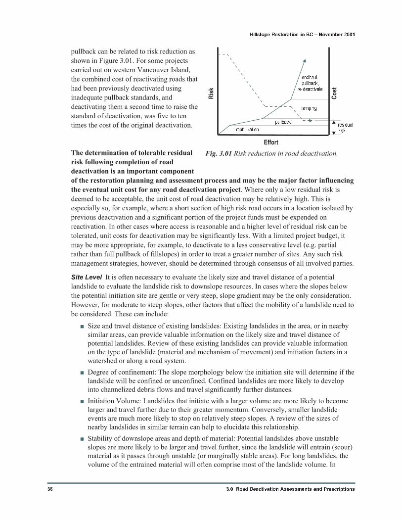
pullback can be related to risk reduction as
shown in Figure 3.01. For some projects
carried out on western Vancouver Island,
the combined cost of reactivating roads that
had been previously deactivated using
inadequate pullback standards, and
deactivating them a second time to raise the
standard of deactivation, was five to ten
times the cost of the original deactivation.
The determination of tolerable residual
risk following completion of road
deactivation is an important component
of the restoration planning and assessment process and may be the major factor influencing
the eventual unit cost for any road deactivation project. Where only a low residual risk is
deemed to be acceptable, the unit cost of road deactivation may be relatively high. This is
especially so, for example, where a short section of high risk road occurs in a location isolated by
previous deactivation and a significant portion of the project funds must be expended on
reactivation. In other cases where access is reasonable and a higher level of residual risk can be
tolerated, unit costs for deactivation may be significantly less. With a limited project budget, it
may be more appropriate, for example, to deactivate to a less conservative level (e.g. partial
rather than full pullback of fillslopes) in order to treat a greater number of sites. Any such risk
management strategies, however, should be determined through consensus of all involved parties.
Site Level It is often necessary to evaluate the likely size and travel distance of a potential
landslide to evaluate the landslide risk to downslope resources. In cases where the slopes below
the potential initiation site are gentle or very steep, slope gradient may be the only consideration.
However, for moderate to steep slopes, other factors that affect the mobility of a landslide need to
be considered. These can include:
� Size and travel distance of existing landslides: Existing landslides in the area, or in nearby
similar areas, can provide valuable information on the likely size and travel distance of
potential landslides. Review of these existing landslides can provide valuable information
on the type of landslide (material and mechanism of movement) and initiation factors in a
watershed or along a road system.
� Degree of confinement: The slope morphology below the initiation site will determine if the
landslide will be confined or unconfined. Confined landslides are more likely to develop
into channelized debris flows and travel significantly further distances.
� Initiation Volume: Landslides that initiate with a larger volume are more likely to become
larger and travel further due to their greater momentum. Conversely, smaller landslide
events are much more likely to stop on relatively steep slopes. A review of the sizes of
nearby landslides in similar terrain can help to elucidate this relationship.
� Stability of downslope areas and depth of material: Potential landslides above unstable
slopes are more likely to be larger and travel further, since the landslide will entrain (scour)
material as it passes through unstable (or marginally stable areas). For long landslides, the
volume of the entrained material will often comprise most of the landslide volume. In
36 3.0 Road Deactivation Assessments and Prescriptions
Hillslope Restoration in BC � November 2001
Fig. 3.01 Risk reduction in road deactivation.
Ris
k
residualrisk
Co
st
Effort
endhaul,pullback,
re-deactivate
ramping
mobilization
pullback
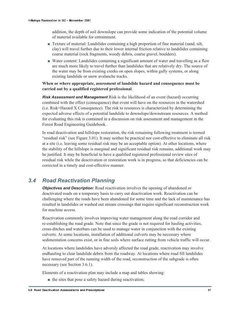
addition, the depth of soil downslope can provide some indication of the potential volume
of material available for entrainment.
� Texture of material: Landslides containing a high proportion of fine material (sand, silt,
clay) will travel further due to their lower internal friction relative to landslides containing
coarse material (rock fragments, woody debris, coarse gravel, boulders).
� Water content: Landslides containing a significant amount of water and travelling as a flow
are much more likely to travel further than landslides that are relatively dry. The source of
the water may be from existing creeks on open slopes, within gully systems, or along
existing landslide or snow avalanche tracks.
When or where appropriate, assessment of landslide hazard and consequence must be
carried out by a qualified registered professional.
Risk Assessment and Management Risk is the likelihood of an event (hazard) occurring
combined with the effect (consequence) that event will have on the resources in the watershed
(i.e. Risk=Hazard X Consequence). The risk to resources is characterized by determining the
expected adverse effects of a potential landslide to downslope/downstream resources. A method
for evaluating this risk is contained in a discussion on risk assessment and management in the
Forest Road Engineering Guidebook.
In road deactivation and hillslope restoration, the risk remaining following treatment is termed
“residual risk” (see Figure 3.01). It may neither be practical nor cost-effective to eliminate all risk
at a site (i.e. leaving some residual risk may be an acceptable option). At other locations, where
the stability of the hillslope is marginal and significant residual risk remains, additional work may
be justified. It may be beneficial to have a qualified registered professional review sites of
residual risk while the deactivation or restoration work is in progress, so that deficiencies can be
corrected in a timely and cost-effective manner.
3.4 Road Reactivation Planning
Objectives and Description: Road reactivation involves the opening of abandoned or
deactivated roads on a temporary basis to carry out deactivation work. Reactivation can be
challenging where the roads have been abandoned for some time and the lack of maintenance has
resulted in landslides or washed out stream crossings that require significant reconstruction work
for machine access.
Reactivation commonly involves improving water management along the road corridor and
re-establishing the road grade. Note that since the grade is not required for hauling activities,
cross-ditches and waterbars can be used to manage water in conjunction with the existing
culverts. At some locations, installation of additional culverts may be necessary where
sedimentation concerns exist, or in fine soils where surface rutting from vehicle traffic will occur.
At locations where landslides have adversly affected the road grade, reactivation may involve
endhauling to clear landslide debris from the roadway. At locations where road fill landslides
have removed part of the running width of the road, reconstruction of the subgrade is often
necessary (see Section 3.6.1).
Elements of a reactivation plan may include a map and tables showing:
� the sites that pose a safety hazard during reactivation;
3.0 Road Deactivation Assessments and Prescriptions 37
Hillslope Restoration in BC � November 2001
� road stations with prescriptions for armoured swales, cross-ditches, and waterbars;
� site specific sketches for road reconstruction, prepared/reviewed as necessary by a qualified
registered professional;
� location of streams and fisheries habitat in the watershed to assist in the planning of fish
salvage and sediment control measures during reactivation and deactivation;
� a list of new culverts or portable bridges required for installation during reactivation, if any.
Benefits: Unstable and/or sensitive terrain often requires more careful reactivation to prevent an
increase in landslide or sedimentation hazards. The preparation of a reactivation plan during the
prescription process can provide important guidance for site staff organizing and carrying out
reactivation activities. Reactivation plans can also identify sites for environmental monitoring and
agency notification (and approval, where appropriate). Reactivation plans may also provide an
increased level of due diligence where appropriate.
Often the assessment for reactivation can be completed concurrently with deactivation
prescriptions. The methodology is the same, namely noting existing features and the needed
techniques for reactivation by station along the road.
Developing reactivation plans can be beneficial where there are:
� numerous reactivation problem sites and/or safety concerns;
� narrow roads with likely machine
access problems;
� roads with stability or erosion
problems such that careful water
management during reactivation is
necessary;
� overgrown roads with stability and
water management concerns
(structurally unsound bridges or
culverts);
� roads to be kept open for more than
one season to complete deactivation
work (for increased due diligence);
� previously deactivated roads with
moderate to heavy pullback that
require re-opening.
Considerations: Road reactivation
planning can vary greatly, depending on the
existing conditions of the road. Where the
costs of reactivation of a road (or a portion
of road) may outweigh the potential benefits
of deactivation, an assessment of risk to
downslope and downstream resources by a
qualified registered professional may be
warranted. For example, road reactivation
costs along road segments of previous
38 3.0 Road Deactivation Assessments and Prescriptions
Hillslope Restoration in BC � November 2001
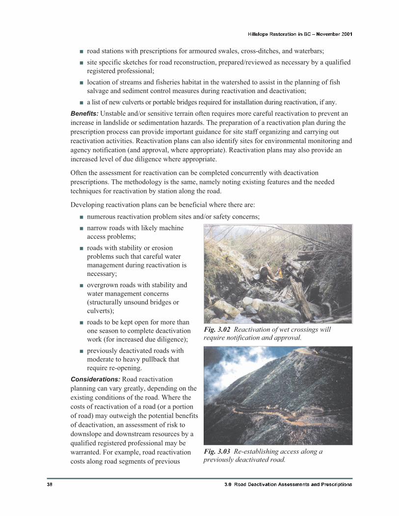
Fig. 3.02 Reactivation of wet crossings willrequire notification and approval.
Fig. 3.03 Re-establishing access along apreviously deactivated road.
pullback can be extremely costly, and pose site specific safety hazards. Assessment of such a
situation must consider the potential safety of the operator and crew using the road, water
management along the reactivated road, the cost of the reactivation, and the expected decrease in
landslide hazard as a result of improved deactivation
3.5 Deactivation Technique Descriptions
The following are typical measures carried out during deactivation. They are often combined at
specific locations. For example, at a single culvert location the deactivation prescription may be
“Pull Metal Culvert” and “Cross-ditch”, or sections with a prescription for “Scarification” may be
in conjunction with a prescription for “Insloping” for water control.
The descriptions are divided into two parts: water management (Sections 3.5.1 to 3.5.11) and road
fill pullback (Sections 3.5.12 to 3.5.14). Commonly, road fill pullback will be carried out along
sections of road, while water management techniques may be carried out at specific locations
within or adjacent to the pullback.
Some previous discussions of road deactivation techniques have sub-divided some of the
techniques listed below into more than one operation. For example, the Advanced Road
Deactivation Course contains separate prescriptions for heavy pullback and gully restoration.
However, in terms of the principles involved and the work carried out, these are both variations of
full road fill pullback. While separating them may be beneficial for cost estimates, at times it
unnecessarily complicates prescriptions.
All road deactivation practitioners are encouraged to develop clear, effective symbols and
prescriptions that best address stability, sedimentation, and site productivity objectives in a
particular operating area. A review by operations staff may result in valuable feedback that can
make the prescriptions less ambiguous. Alternatively, some operations may have an established
set of symbols and prescription formats that are appropriate for their use. The symbols and system
in the Advanced Road Deactivation Course (BCFCSN, 1997) may also be used.
Coastal and Interior factors are also discussed in the prescriptions, especially with respect to the
prescription indicators and cost factors for each technique. For areas where coarse rock is not
available for armouring, emphasis should be placed on alternatives such as revegetation, erosion
control blankets, or perhaps soil bioengineering installations.
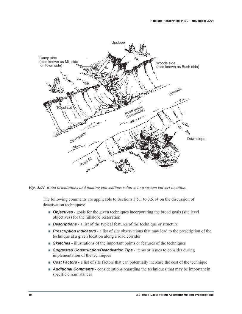
For the following descriptions, Figure 3.04 shows some of the common terms used to denote road
components and relative directions. Deactivation is most commonly carried out from the woods
side to the camp side.
3.0 Road Deactivation Assessments and Prescriptions 39
Hillslope Restoration in BC � November 2001
The following comments are applicable to Sections 3.5.1 to 3.5.14 on the discussion of
deactivation techniques:
� Objectives - goals for the given techniques incorporating the broad goals (site level
objectives) for the hillslope restoration
� Descriptions - a list of the typical features of the technique or structure
� Prescription Indicators - a list of site observations that may lead to the prescription of the
technique at a given location along a road corridor
� Sketches - illustrations of the important points or features of the techniques
� Suggested Construction/Deactivation Tips - items or issues to consider during
implementation of the techniques
� Cost Factors - a list of site factors that can potentially increase the cost of the technique
� Additional Comments - considerations regarding the techniques that may be important in
specific circumstances
40 3.0 Road Deactivation Assessments and Prescriptions
Hillslope Restoration in BC � November 2001
Upslope
Road cut
Camp side(also known as Mill sideor Town side)
Downgrade
Road grade
(favourable)
Woods side(also known as Bush side)
Upgrade
Downslope
Road fill
Fig. 3.04 Road orientations and naming conventions relative to a stream culvert location.
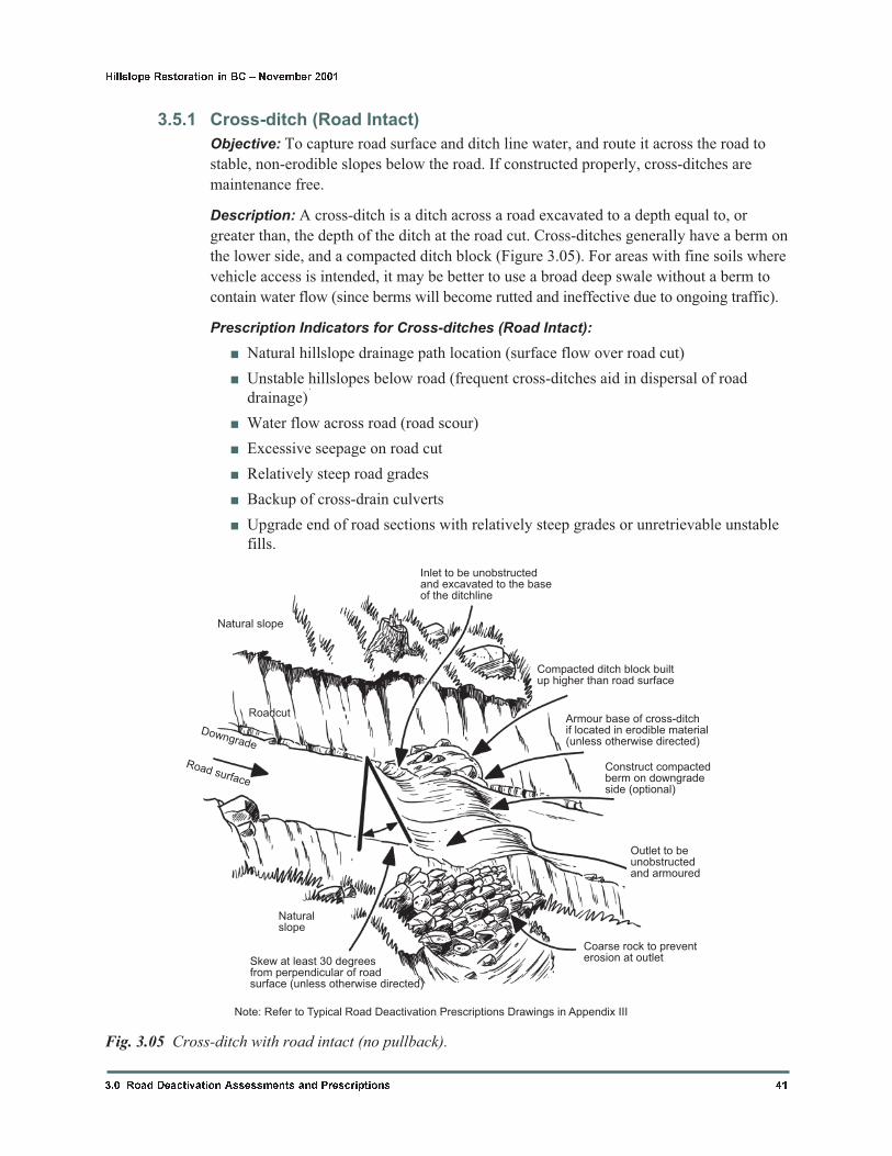
3.5.1 Cross-ditch (Road Intact)
Objective: To capture road surface and ditch line water, and route it across the road to
stable, non-erodible slopes below the road. If constructed properly, cross-ditches are
maintenance free.
Description: A cross-ditch is a ditch across a road excavated to a depth equal to, or
greater than, the depth of the ditch at the road cut. Cross-ditches generally have a berm on
the lower side, and a compacted ditch block (Figure 3.05). For areas with fine soils where
vehicle access is intended, it may be better to use a broad deep swale without a berm to
contain water flow (since berms will become rutted and ineffective due to ongoing traffic).
Prescription Indicators for Cross-ditches (Road Intact):
� Natural hillslope drainage path location (surface flow over road cut)
� Unstable hillslopes below road (frequent cross-ditches aid in dispersal of road
drainage)1
� Water flow across road (road scour)
� Excessive seepage on road cut
� Relatively steep road grades
� Backup of cross-drain culverts
� Upgrade end of road sections with relatively steep grades or unretrievable unstable
fills.
3.0 Road Deactivation Assessments and Prescriptions 41
Hillslope Restoration in BC � November 2001
Inlet to be unobstructedand excavated to the baseof the ditchline
Compacted ditch block builtup higher than road surface
Armour base of cross-ditchif located in erodible material(unless otherwise directed)
Construct compactedberm on downgradeside (optional)
Outlet to beunobstructedand armoured
Coarse rock to preventerosion at outletSkew at least 30 degrees
from perpendicular of roadsurface (unless otherwise directed)
Naturalslope
Road surface
Downgrade
Roadcut
Natural slope
Note: Refer to Typical Road Deactivation Prescriptions Drawings in Appendix III
Fig. 3.05 Cross-ditch with road intact (no pullback).
Notes:
1. Frequent cross-ditches can be used to disperse hillslope drainage above and/or
upgrade of unstable hillslopes. Consider consulting a qualified registered professional
regarding the landslide hazard and risk at the site.
Suggested Construction Tips for Cross-ditches (Road Intact):
� As the outlet location is more important than the inlet to establish the gradient of
the cross-ditch, start at the outlet by pulling back all woody debris and potentially
unstable/erodible road fill.
� Make sure the cross-ditch inlet is deeper than the base of the existing road ditch,
and the entire cross-ditch excavation is adequately sloped to resist sediment
deposition. The size, depth, and shape of the cross-ditch will depend on the access
requirements and the expected flows. If vehicle access is to be retained, gently
slope the cross-ditch approaches. Note that on steep grades, the large berm needed
to contain flow in the cross-ditch may preclude access. For steep grades an increase
in skew may be necessary to reduce deposition in the cross-ditch.
� The ditch block must be relatively impermeable and non-erodible and large enough
to divert expected flows into the cross-ditch. For permanent or semi-permanent
deactivation, the ditch block is normally higher than the road surface. It preferably
contains a mix of rock and soil, keyed into the road cut where necessary.
� Berms must be compacted and large enough to contain the expected flows, and
located on the downgrade side of the cross-ditch for both favourable and adverse
grades. For areas of fine soils, consider using a broad, deep swale to contain flow
instead of a berm.
� Armour base of cross-ditch if erosion is expected to cause a problem for future road
access. Use angular or sub-angular rock large enough for armouring against
expected flows but small enough to allow for safe vehicle passage.
� Armour the outlet of the cross-ditch, unless noted in the prescriptions. Size and
placement of the armour will depend on the anticipated flows and downstream
consequences. Use angular rock large enough to protect exposed soil, but small
enough not to divert or obstruct flows. For areas without coarse rock, suitable
alternatives may include careful grading to form gentle sidewall slopes,
revegetation, erosion control mats, sand bags, soil bioengineering structures, or
appropriately sized and placed woody debris.
Increased Cost Factors for Cross-ditches (Road Intact):
� Gully locations (gully restoration)1
� Depth of road fill at outlet
� Rocky road fill or lots of large woody debris in road grade
� Road width or landing width
� Lack of suitable armour; importing required2
� Heavy woody debris at outlet
� Sediment control and monitoring3
� Strict timing constraints3
42 3.0 Road Deactivation Assessments and Prescriptions
Hillslope Restoration in BC � November 2001
� Excessive road fills (large volume at outlet)
� Endhauling of excavated material necessary to maintain access
Notes:
1. Cross-ditch locations at gully crossings can involve more armouring and/or
endhauling of material if excavated material cannot be placed against the road cut.
2. Importing of rock can be very expensive depending on haul distance and quarrying
costs.
3. The connectivity of the stream to fish habitat or water supply areas increases the need
for sediment control during cross-ditch excavation.
Additional Comments for Cross-ditches (Road Intact):
� All road fill material must be removed from the outlet area; this is particularly
important for preventing landslides. Outlets of cross-ditches should not divert water
onto erodible or unstable slopes.
� Larger expected flows and steeper road grades will usually require more frequent
cross-ditches of greater size. Where ditches are deeply eroded, regrading of the
ditch line may be needed.
� Backup cross-ditches at culvert locations (also known as “failsafes”) are installed
directly downgrade of the culvert location. At some locations, it may be appropriate
to install these directly above or alongside the culvert; however, care must be taken
to leave an adequate thickness of fill over the existing culvert. For backup
cross-ditches of cross-drain culverts in erodible soils, locating the cross-ditch about
5m downgrade of the culvert may prevent a culvert washout and reduce
maintenance costs. The backup cross-ditches must be large enough to handle the
expected flow, and similar in design and construction to a regular cross-ditch.
Backup cross-ditches must also maintain the pre-construction stream location for
stream culverts.
� Cross-ditches that are located at low points in the road grade (receive water from
both directions along road) need neither a ditch block nor a berm. In this case, the
cross-ditch can be constructed as a broad, gentle swale.
� Careful assessment is necessary for outlet locations where significant flows are
expected in the cross-ditch, and the outlet is located outside a natural channel. In
these cases, the flow may cause erosion or stability problems downslope.
� Cross-ditches should be constructed to allow vehicle access commensurate with the
Access Management Plan.
3.0 Road Deactivation Assessments and Prescriptions 43
Hillslope Restoration in BC � November 2001
3.5.2 Cross-ditch In Full Pullback
Objective: To restore the natural hillslope drainage paths to historic (pre-construction)
locations along the hillslope, through road fill pullback.
Description: A cross-ditch in pullback is a ditch across the old roadbed connecting a
natural hillslope drainage path (streams, gully channels, and swales with flow).
Cross-ditches in pullback usually must be excavated down to natural (undisturbed),
non-erodible material. The size, depth, and shape of the cross-ditch should mimic the
44 3.0 Road Deactivation Assessments and Prescriptions
Hillslope Restoration in BC � November 2001
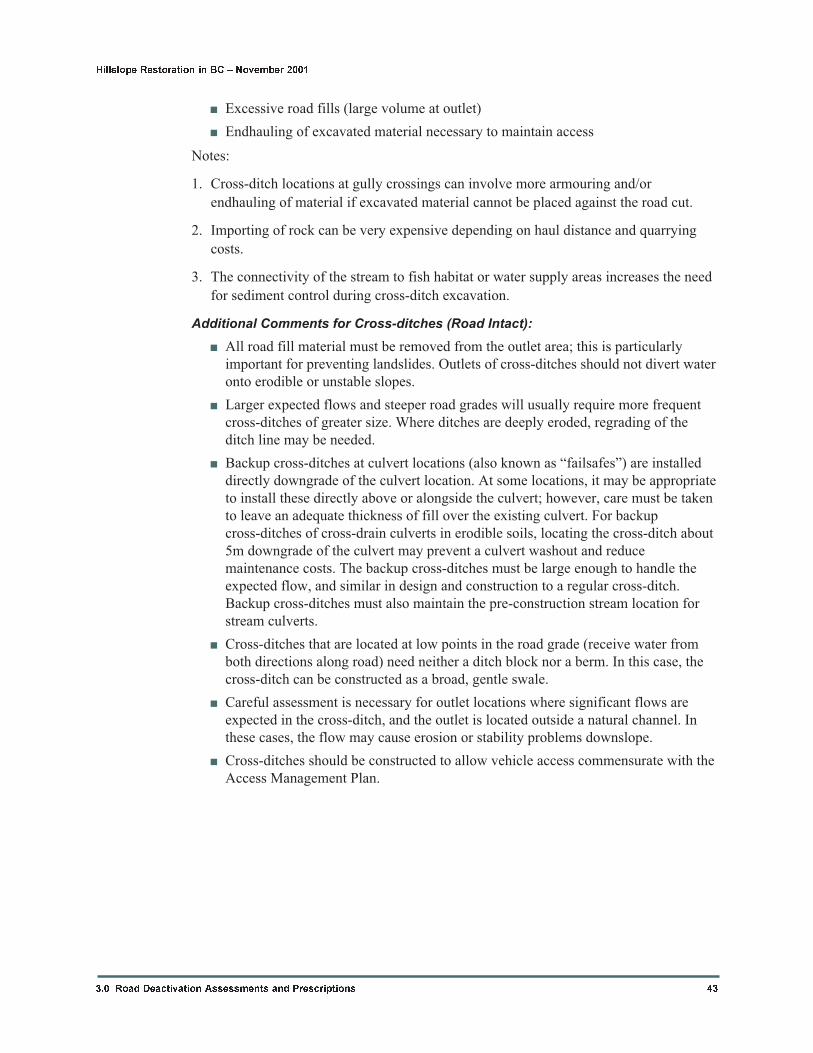
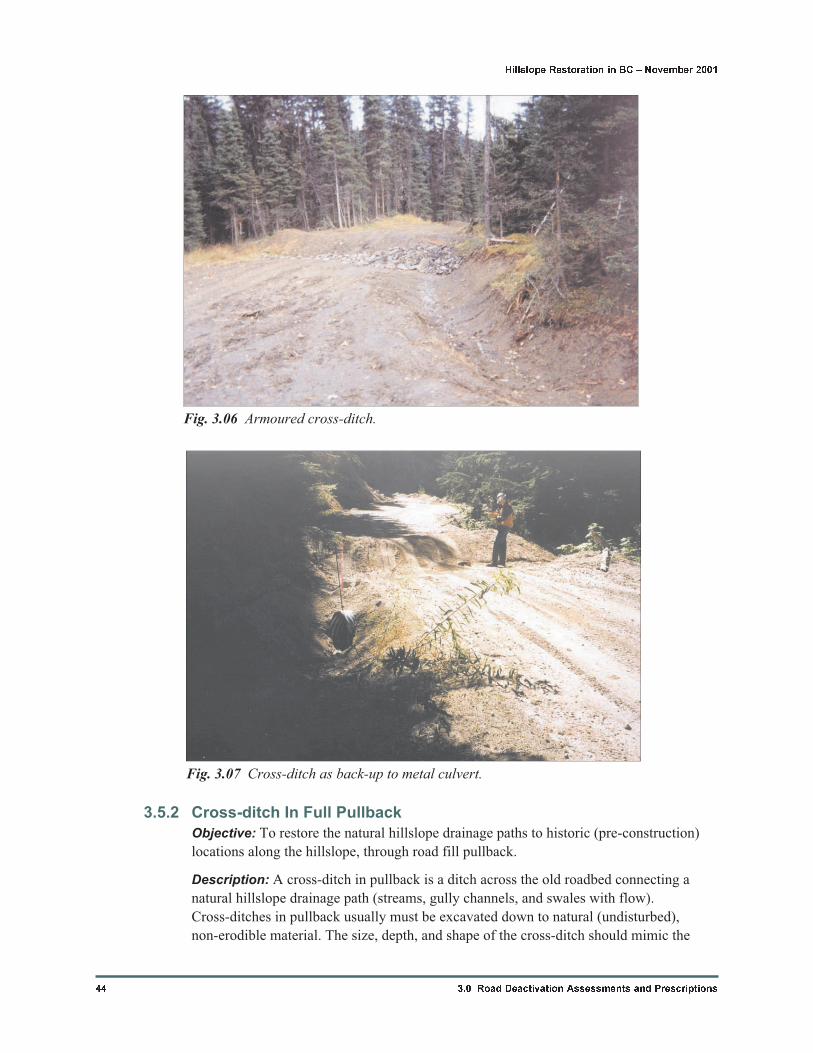
Fig. 3.07 Cross-ditch as back-up to metal culvert.
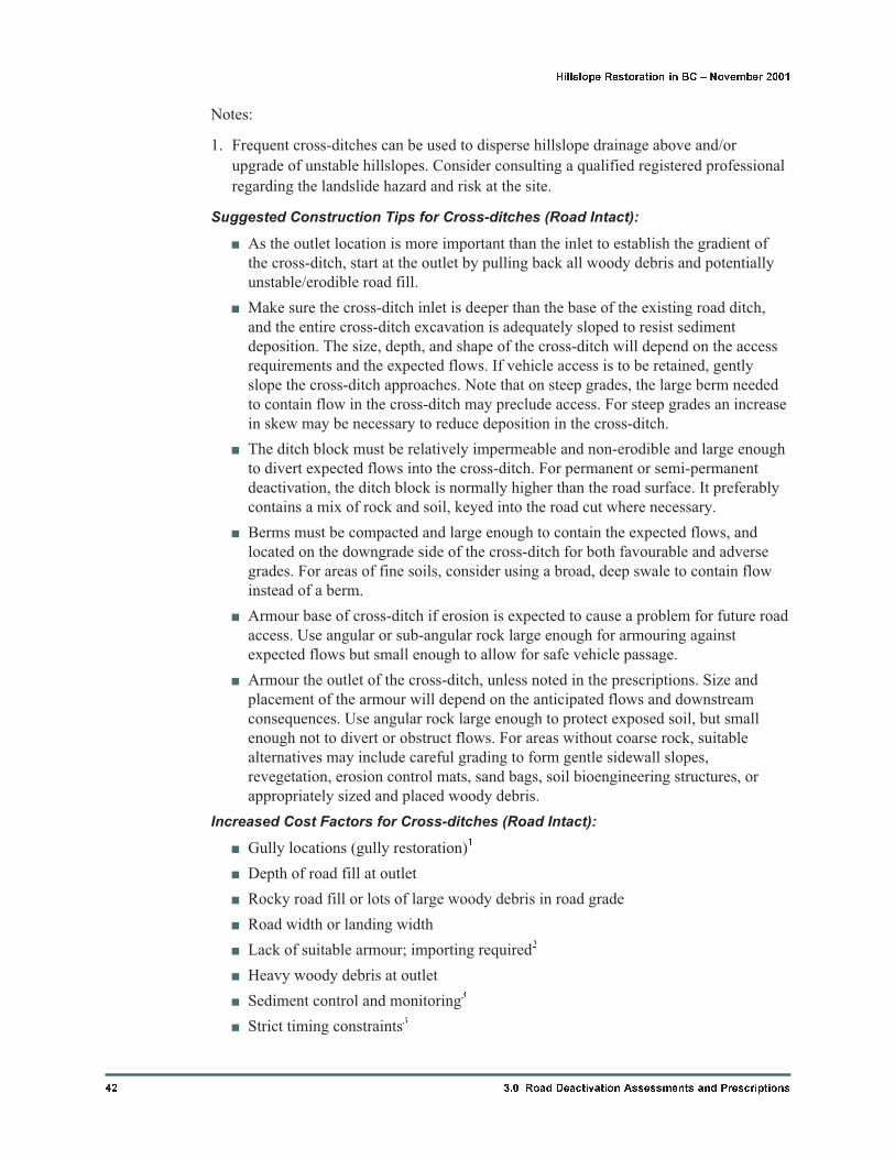
Fig. 3.06 Armoured cross-ditch.
nearby natural ground profiles and contours (Figure 3.09). Since no water flow along the
road surface is possible in areas of road fill pullback, fewer cross-ditches are needed in
pullback than for roads where no pullback is carried out.
Prescription Indicators for Cross-ditches (Road Fill Pullback):
� Road crosses natural hillslope drainage path (surface flow over road cut)
� Excessive and defined seepage areas (“piping flow” or bedrock swales)
� Upgrade or downgrade side of placed pullback material1
� Road is unstable or has erodible slope below and it is important to maintain
dispersed drainage across the hillslope
Note:
1. Constructing a cross-ditch upgrade of pullback sections will prevent erosion along the
toe of the pullback material. Constructing a cross-ditch on the downgrade side will
prevent accumulation of water if the roadbed remains intact (i.e. has not been
decompacted and outsloped prior to placement of pullback material) under the road
fill pullback material.
Suggested Construction Tips for Cross-ditches (Road Fill Pullback):
� If armouring is needed, stockpile available rock during road fill pullback
approaching the cross-ditch.
� Decompact and outslope the road surface as part of road fill pullback adjacent to
the cross-ditch (see Section 3.5.14).
� Remove ballast from cross-ditch location and excavate a bench to position machine
for further reach downslope. Place material on the woods side bench.
3.0 Road Deactivation Assessments and Prescriptions 45
Hillslope Restoration in BC � November 2001
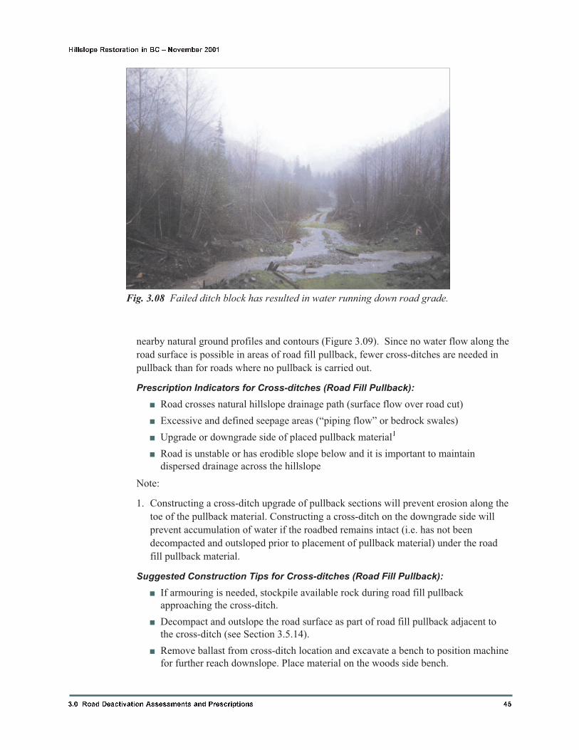
Fig. 3.08 Failed ditch block has resulted in water running down road grade.
� Clear outlet of debris and road fill. Place material on the woods side bench. Do not
leave excavated material on the outside of the road if potentially unstable.
� Excavate cross-ditch from outlet to inlet, exposing native ground for the full length
of the cross-ditch. Place as much material on the woods side, and fill the bench to
the top of the slope. Place armour as required; excavate as “steps” if insufficient
armour is available to cover all flow areas. Do not leave oversteepened sideslopes
on the cross-ditch, particularly in fine soils.
� Finish the sidewall on camp side prior to finishing cross-ditch pullback.
� At gully locations, blend slopes of pullback into existing slopes above and below
the road, in and out of the gully.
Increased Cost Factors for Cross-ditches (Road Fill Pullback):
� Gully locations (gully restoration)1
� Depth of road fill at outlet
� Rocky road fill, or lots of large woody debris in road grade
� Road width or landing width
� Armour required; lack of available armour
� Endhauling of excavated material (cannot place material in road cut)
� Sediment control and monitoring2
46 3.0 Road Deactivation Assessments and Prescriptions
Hillslope Restoration in BC � November 2001
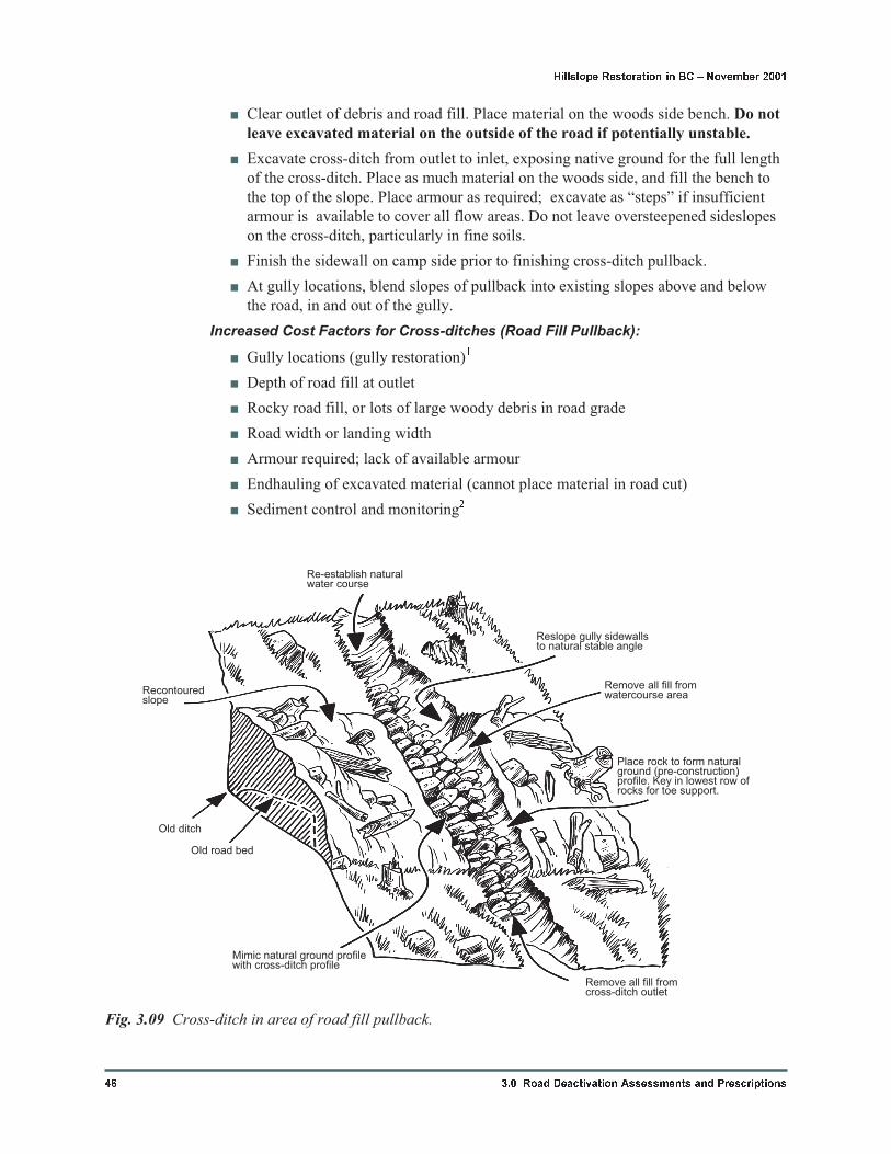
Recontouredslope
Old ditch
Old road bed
Mimic natural ground profilewith cross-ditch profile
Re-establish naturalwater course
Reslope gully sidewallsto natural stable angle
Remove all fill fromwatercourse area
Place rock to form naturalground (pre-construction)profile. Key in lowest row ofrocks for toe support.
Remove all fill fromcross-ditch outlet
Fig. 3.09 Cross-ditch in area of road fill pullback.
� Strict timing constraints2
� Heavy woody debris at outlet
� Excessive road fills (large volume at outlet)
Notes:
1. Cross-ditch locations at gully crossings typically involve the removal of more road fill
and less space on the bench for pullback (consider endhauling).
2. The connectivity of the cross-ditch to fish habitat or water supply areas increases the
need for sediment control and adherence to timing windows and measures during
cross-ditch excavation.
Additional Comments for Cross-ditches (Road Fill Pullback):
� All road fill material must be removed from the outlet area; this is particularly
important for preventing landslides. Outlets of cross-ditches should not divert water
onto erodible or unstable slopes.
� Armour placement (volume and size) is dependent on anticipated flows and
downstream consequences. Armouring may not be needed in cases of very low flow
or where the flow is not hydraulically connected to larger streams in the watershed
(fish habitat or water supply areas).
� Outlets and the cross-ditch base should be armoured if the cross-ditch is located in
erodible material (as compared to the natural stream channel materials). The armour
must be small enough so that it does not divert flows. Armouring may not be
needed if the cross-ditch is excavated into natural (undisturbed) ground, or if no
sedimentation is expected.
� In pullback, skew is only necessary to line up natural hillslope drainage paths.
� For frozen roads in fine soils, cross-ditches can be difficult to maintain due to
rutting from ongoing traffic. Consider armouring ditches (provided that diverted
water does not cause stability problems) or using steel cattleguard-type structures as
alternatives.
� Other possible prescriptions at locations where the room on the bench is needed for
pullback material and coarse rock is available are trench drains (see Section 3.5.6)
and blanket drains (see Section 3.5.7).
� Stream restorations at stream crossings are similar to cross-ditches but require
restoring the width of the stream as well as armouring the channel. Reconstruction
of streambanks should mimic upstream and downstream channel geometry and
bank materials. Consider also excavating a stepped channel in non-erodible
materials to reduce the flow energy if erodible materials are present downslope.
These sites may warrant specific comments as part of the prescriptions. At critical
sites it may be necessary to consult a specialist with expertise in stream hydrology.
At sites that are expected to impact fish habitat, review by a fisheries habitat
specialist is prudent.
3.0 Road Deactivation Assessments and Prescriptions 47
Hillslope Restoration in BC � November 2001
3.5.3 Waterbars
Objective: To divert water off the road onto the fillslope to prevent erosion of road
surface. Reverse waterbars direct flow off the road into the ditch.
Description: A waterbar is a shallow ditch across a road, skid trail, or backspar trail to
prevent excessive flow down the road surface (or trail). Waterbars are not intended to
intercept ditch lines; thus, the base of the waterbar is above the base of the ditch and no
ditch block is required. Waterbars are used where a road is kept open for vehicle traffic,
or where cross-ditches cannot be used (such as throughcuts). Waterbars may not include a
berm if traffic along the road is expected to cause rutting and render the berms
ineffective.
Prescription Indicators for Waterbars:
� Surface flow on road grade (road scour)
� Relatively steep road grades where ditch remains intact
� Throughcut with steep grades, surface erosion expected
� Upgrade of switchback to keep water off steep road grade at switchback
� Reverse waterbar where water needs to be kept off unstable road fill and can be
carried in stable ditch
Suggested Construction Tips for Waterbars:
� In coarse soil and rock, place excavated material from the waterbar immediately
downgrade to form a berm (as for cross-ditches); use excavator bucket to compact
if road traffic is expected. In fine soil, consider using a broad swale with no berm.
� Waterbars do not have to cross the entire road surface to be effective; they must
only intercept flow on the road and divert it off the road
� Waterbars must be shallow enough to allow for unimpeded vehicle access
� Consider using a herringbone pattern in throughcuts to divide the flow between the
two sides. Ditching may also be necessary if the road is not sloped, or the surface is
erodible.
48 3.0 Road Deactivation Assessments and Prescriptions
Hillslope Restoration in BC � November 2001
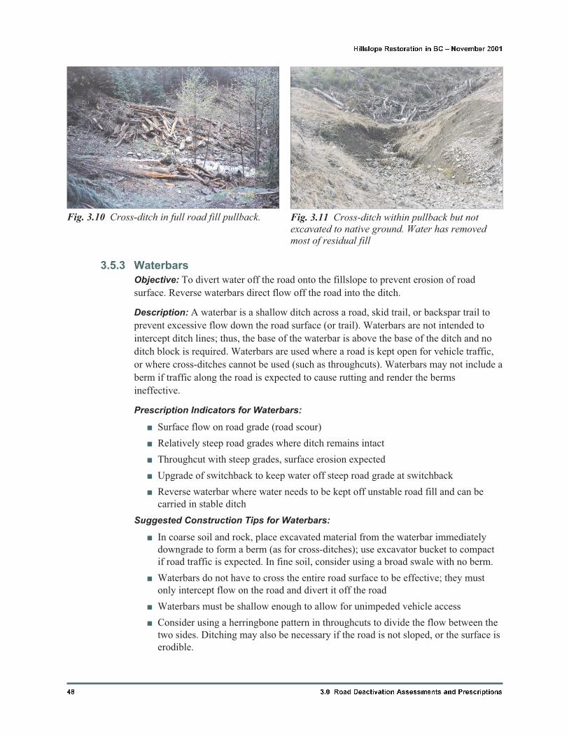
Fig. 3.10 Cross-ditch in full road fill pullback. Fig. 3.11 Cross-ditch within pullback but notexcavated to native ground. Water has removedmost of residual fill
� Waterbars can be constructed with bulldozers or graders, depending on material
type and amount of intended use of the road; however, these machines are not
suited for placement of armour.
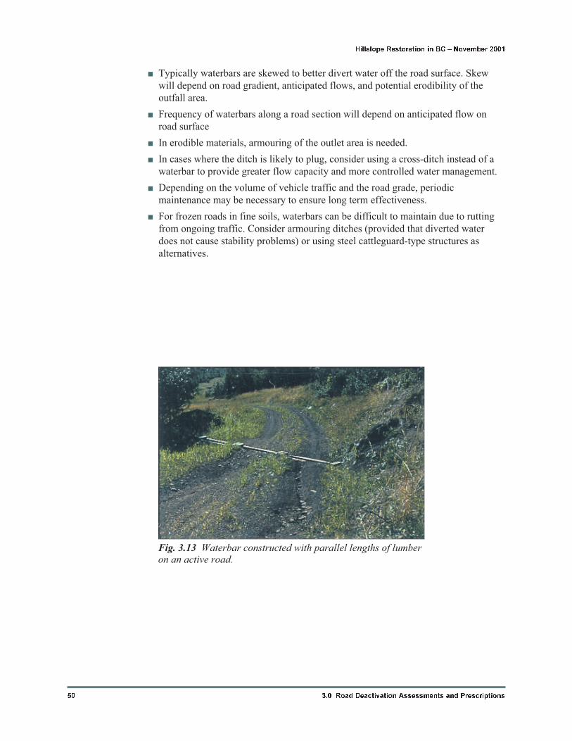
� Waterbars constructed of parallel lengths of lumber (e.g. 2x4’s) embedded in the
road grade may be appropriate on active roads (Figure 3.13).
Increased Cost Factors for Waterbars:
� Dense road surface materials
� Depth of road fill at outlet
� Heavy woody debris at outlet
� Road width or landing width
� Armour required; lack of available armour
� Strict timing constraints1
� Sediment control and monitoring1
Notes:
1. The connectivity of the waterbar to fish habitat or water supply areas increases the
need for sediment control and adherence to timing windows and measures during
waterbar excavation.
Additional Comments for Waterbars:
3.0 Road Deactivation Assessments and Prescriptions 49
Hillslope Restoration in BC � November 2001
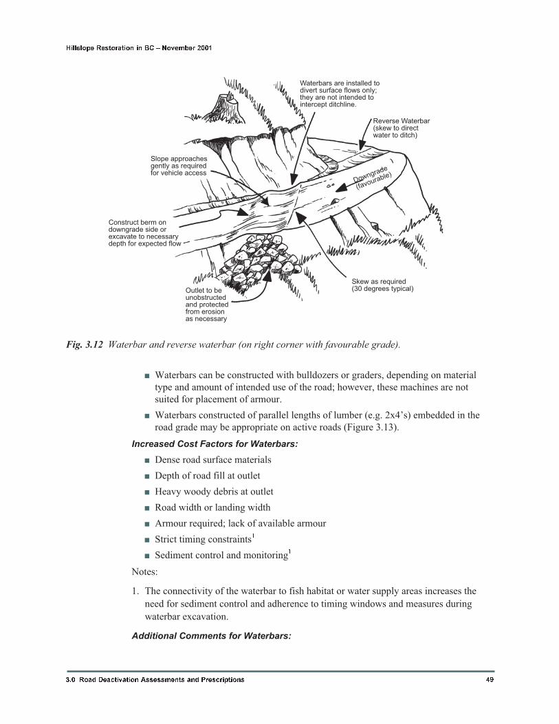
Waterbars are installed todivert surface flows only;they are not intended tointercept ditchline.
Reverse Waterbar(skew to directwater to ditch)
Slope approachesgently as requiredfor vehicle access
Construct berm ondowngrade side orexcavate to necessarydepth for expected flow
Outlet to beunobstructedand protectedfrom erosionas necessary
Skew as required(30 degrees typical)
Downgrade
(favourable)
Fig. 3.12 Waterbar and reverse waterbar (on right corner with favourable grade).
� Typically waterbars are skewed to better divert water off the road surface. Skew
will depend on road gradient, anticipated flows, and potential erodibility of the
outfall area.
� Frequency of waterbars along a road section will depend on anticipated flow on
road surface
� In erodible materials, armouring of the outlet area is needed.
� In cases where the ditch is likely to plug, consider using a cross-ditch instead of a
waterbar to provide greater flow capacity and more controlled water management.
� Depending on the volume of vehicle traffic and the road grade, periodic
maintenance may be necessary to ensure long term effectiveness.
� For frozen roads in fine soils, waterbars can be difficult to maintain due to rutting
from ongoing traffic. Consider armouring ditches (provided that diverted water
does not cause stability problems) or using steel cattleguard-type structures as
alternatives.
50 3.0 Road Deactivation Assessments and Prescriptions
Hillslope Restoration in BC � November 2001
Fig. 3.13 Waterbar constructed with parallel lengths of lumberon an active road.
3.5.4 Metal Pipe Culvert Removal (Sediment Control)
Objective: To remove the existing stream culvert with the least amount of sedimentation
possible and leave a cross-ditch. This technique is recommended where running water is
present and the stream is hydraulically connected to fish habitat or community water
supplies. If no water is present, no sedimentation concerns exist and cross-ditch technique
can be used (Section 3.5.1 cross-ditch for road intact, 3.5.2 for cross-ditch in full
pullback).
Description: Often, pipe culverts must be pulled and cross-ditches constructed where
culvert maintenance is impractical or impossible (Figure 3.14). This technique can allow
for culvert removal while water is present in the channel. In cases where the traffic use is
expected to continue, an armoured swale or ford can be constructed following the
removal of the pipe culvert (see Section 3.5.9).
Prescription Indicators for Metal Pipe Culvert Removal (Sediment Control):
� Culvert has inadequate capacity
� Damaged pipe (reduced flow capacity)
� Sediment accumulation at inlet locations (reduced flow capacity)
� Impeding fish passage; fish concerns1
� Improper location of culvert (disrupting hillslope drainage paths)
� Culvert in gully or creek crossing as part of permanent deactivation
3.0 Road Deactivation Assessments and Prescriptions 51
Hillslope Restoration in BC � November 2001
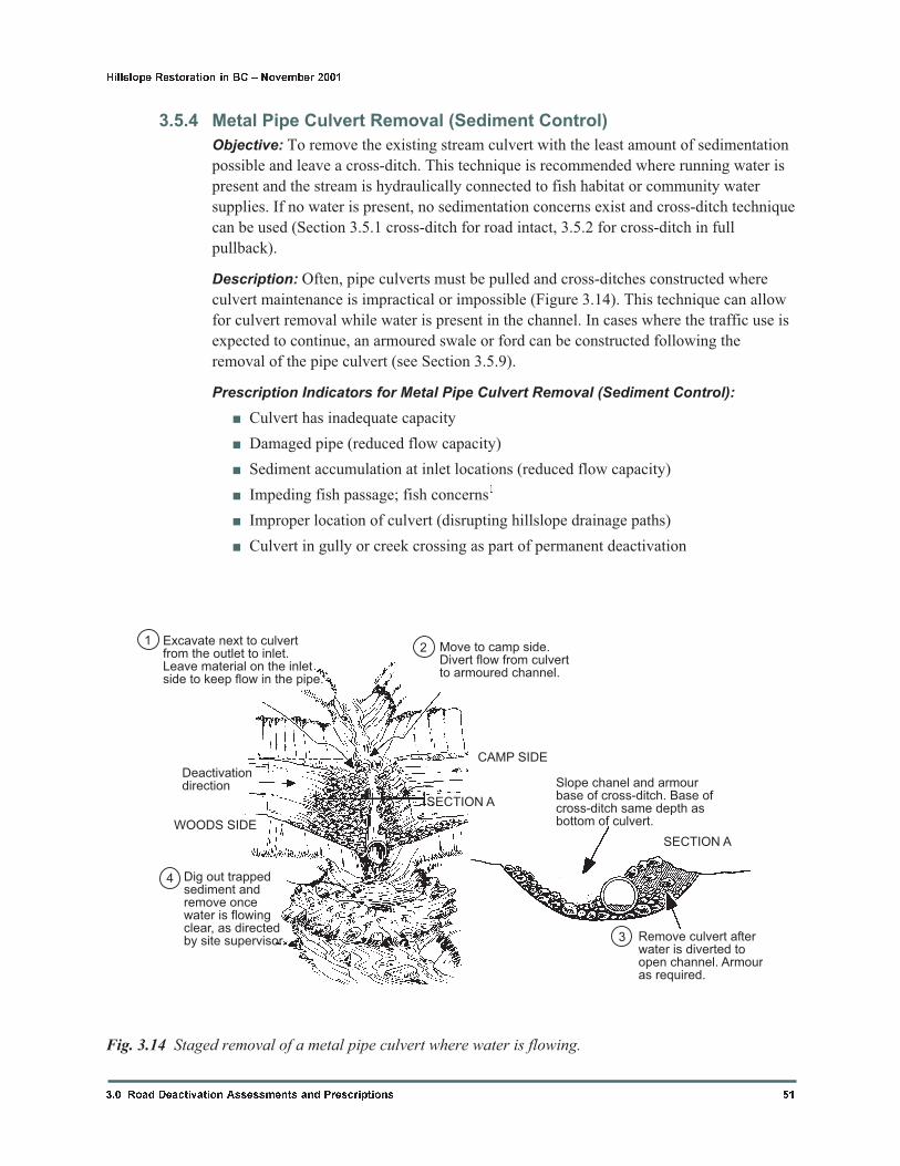
Excavate next to culvertfrom the outlet to inlet.Leave material on the inletside to keep flow in the pipe.
Move to camp side.Divert flow from culvertto armoured channel.
Deactivationdirection
WOODS SIDE
SECTION A
Dig out trappedsediment andremove oncewater is flowingclear, as directedby site supervisor.
Slope chanel and armourbase of cross-ditch. Base ofcross-ditch same depth asbottom of culvert.
SECTION A
Remove culvert afterwater is diverted toopen channel. Armouras required.
CAMP SIDE
12
3
4
Fig. 3.14 Staged removal of a metal pipe culvert where water is flowing.

Note:
1. If fish are present or downstream, designate the site for work during a timing window
or have an environmental monitor on site. Fish exclusion and salvage may be
necessary prior to culvert removal.
Suggested Construction Tips for Metal Culvert Removal (Sediment Control):
� Assess the potential adverse environmental effects at the site. Divert flows if
practical. If water cannot be diverted, install sediment control downstream prior to
work at the site.
� Remove road fill to expose the woods side of the culvert; then remove the road fill
over the culvert. While flow is in the culvert, excavate the road fill from the
downstream side to the upstream side, exposing the side of the culvert. Leave some
material on the upslope side of the road to continue to divert flow into the culvert.
Armour the new channel beside the culvert with rock if necessary. See Figures
3.15a to 3.15c.
� Breach the remaining road fill to route the flow into the new channel. Remove the
culvert and the remaining road fill on the camp side. Armour exposed soil as
required.
Increased Cost Factors for Metal Pipe Culvert Removal (Sediment Control):
� Size of culvert
� Width of road surface and length of culvert
� Amount of road fill over culvert
� Attempts to salvage the pipe1
� Sediment control and monitoring2
� Strict timing constraints2
� Possible fish removal2
� Excessive road fills (large volume at outlet)
� Heavy woody debris at outlet
� Amount of rock available for armouring3
Notes:
1. Salvaging metal culverts during removal can increase the time for culvert removal.
2. The connectivity of the cross-ditch to fish habitat or water supply areas increases the
need for sediment and adherence to timing windows and measures control during
excavation.
3. Coarse rock for armouring is much more important for pipe locations at stream
crossings. Culverts that only drain ditch water may not need armouring.
Additional Comments for Metal Pipe Culvert Removal (Sediment Control):
� Each location is different and site specific approaches must be used. For complex
sites, discuss options for work at the site with experienced staff and/or fisheries
agencies to reduce the potential sedimentation to acceptable levels.
52 3.0 Road Deactivation Assessments and Prescriptions
Hillslope Restoration in BC � November 2001
� Making and keeping the site as dry as possible is often the most effective means to
prevent sedimentation. Methods may include: diverting water down the ditch line
until the cross-ditch is constructed and armoured provided the ditch line is not
compromised; diverting streamflow using polyurethane pipe (or similar) with
gravity flow; constructing a secondary cross-ditch in non-erodible materials until
the main cross-ditch is complete; pumping flows around working area (if reliable
pump equipment is available).
� The size, depth, and shape of the cross-ditch depends on the expected flows. Blend
sidewalls of the structure to match adjacent slopes.
� If no water is present, removal of culverts in deep road fills often requires four
steps: 1) remove surfacing and road fill on woods side, to expose top of culvert; 2)
slope approach to a suitable grade on woods side if vehicle access is to be
maintained; 3) expose and remove culvert; 4) move to camp side and complete
cross-ditch excavation (slope approach to a suitable grade if vehicle access is to be
maintained).
� Where coarse rock is scarce, use rock preferentially at stream crossings. Consider
prompt revegetation, erosion control matting, or keeping excavated slopes as flat as
possible.
3.0 Road Deactivation Assessments and Prescriptions 53
Hillslope Restoration in BC � November 2001
a)
b) c)
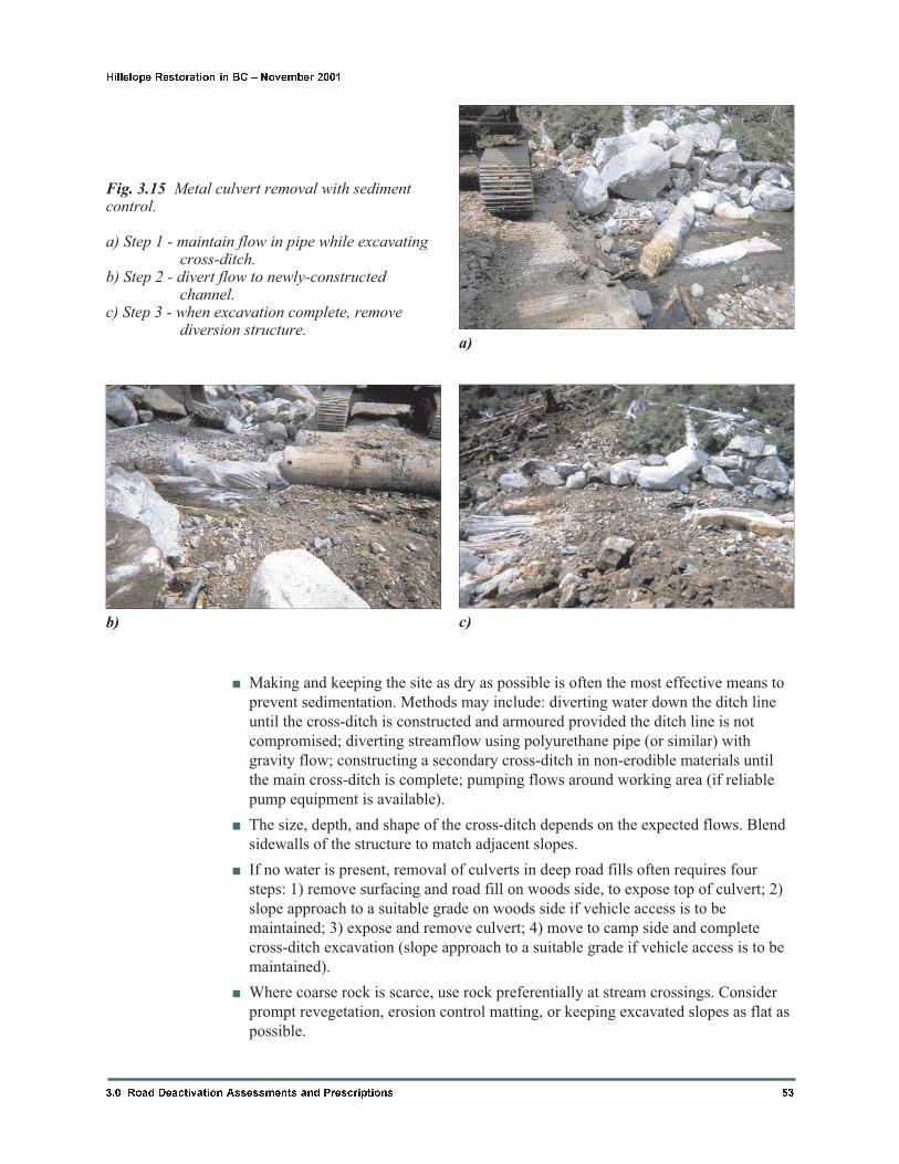
Fig. 3.15 Metal culvert removal with sedimentcontrol.
a) Step 1 - maintain flow in pipe while excavatingcross-ditch.
b) Step 2 - divert flow to newly-constructedchannel.
c) Step 3 - when excavation complete, removediversion structure.
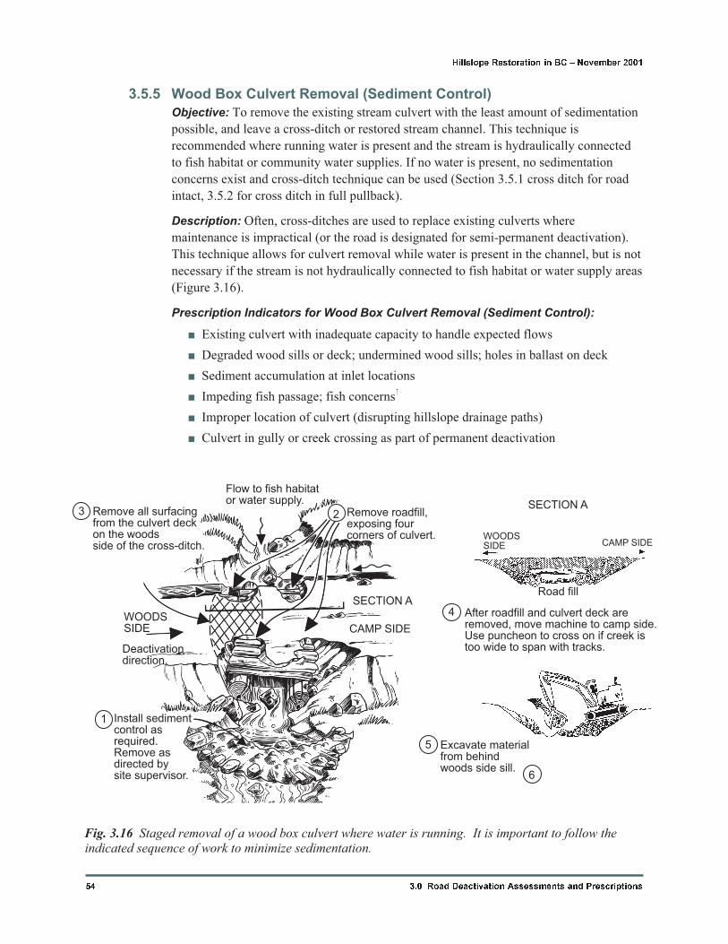
3.5.5 Wood Box Culvert Removal (Sediment Control)
Objective: To remove the existing stream culvert with the least amount of sedimentation
possible, and leave a cross-ditch or restored stream channel. This technique is
recommended where running water is present and the stream is hydraulically connected
to fish habitat or community water supplies. If no water is present, no sedimentation
concerns exist and cross-ditch technique can be used (Section 3.5.1 cross ditch for road
intact, 3.5.2 for cross ditch in full pullback).
Description: Often, cross-ditches are used to replace existing culverts where
maintenance is impractical (or the road is designated for semi-permanent deactivation).
This technique allows for culvert removal while water is present in the channel, but is not
necessary if the stream is not hydraulically connected to fish habitat or water supply areas
(Figure 3.16).
Prescription Indicators for Wood Box Culvert Removal (Sediment Control):
� Existing culvert with inadequate capacity to handle expected flows
� Degraded wood sills or deck; undermined wood sills; holes in ballast on deck
� Sediment accumulation at inlet locations
� Impeding fish passage; fish concerns1
� Improper location of culvert (disrupting hillslope drainage paths)
� Culvert in gully or creek crossing as part of permanent deactivation
54 3.0 Road Deactivation Assessments and Prescriptions
Hillslope Restoration in BC � November 2001
Remove all surfacingfrom the culvert deckon the woodsside of the cross-ditch.
Flow to fish habitator water supply.
Remove roadfill,exposing fourcorners of culvert.
SECTION A
SECTION A
WOODSSIDE
Deactivationdirection.
Install sedimentcontrol asrequired.Remove asdirected bysite supervisor.
Natural slope
CAMP SIDE
After roadfill and culvert deck areremoved, move machine to camp side.Use puncheon to cross on if creek istoo wide to span with tracks.
Remove puncheonand sill from channellaterally to keepsediment from channel.
Excavate materialfrom behindwoods side sill.
1
23
4
5
6
Road fill
Fig. 3.16 Staged removal of a wood box culvert where water is running. It is important to follow theindicated sequence of work to minimize sedimentation.
Note:
1. If fish are present, designate the site for work during a timing window or have an
environmental monitor on site. Fish exclusion and salvage may be necessary prior
to culvert removal.
Suggested Construction Tips for Wood Box Culvert Removal (Water Present):
� Assess the potential adverse environmental effects at the site. Divert flows if
practical. If water cannot be diverted, start by installing sediment control
downstream of the culvert site. Consider attaching filter cloth ‘diaper’ below
superstructure to catch sediment during de-construction.
� Excavate the road fill to expose the ends of the culvert and remove the material
from the deck. Excavate road fill on the woods side to within 0.3m (1ft) of the sill
log, and leave enough material to keep flow in the existing channel.
� Move to camp side of culvert. Remove the woods side sill log, pushing retained
material up and out of the channel.
� Excavate camp side road fill and pull back camp side sill log, pulling soil back and
away from the creek.
Increased Cost Factors for Wood Box Culvert Removal (Sediment Control):
� Size of culvert
� Width of road surface and
length of culvert
� Amount of road fill over
culvert
� Heavy woody debris at outlet
� Sediment control and
monitoring1
� Strict timing constraints1
� Possible fish removal1
� Excessive road fills (large
volume at outlet)
� Cable reinforcement
Notes:
1. Consider potential sediment destabilization before removing embedded large woody
debris from channel.
2. The connectivity of the site to fish habitat or water supply areas increases the need for
sediment control and adherence to timing windows and measures during cross-ditch
excavation.
Additional Comments for Wood Box Culvert Removal (Sediment Control):
� Each location is different and site specific approaches must be used. For complex
sites, discuss options for work at the site with experienced staff and/or fisheries
agencies to reduce the potential sedimentation to acceptable levels.
3.0 Road Deactivation Assessments and Prescriptions 55
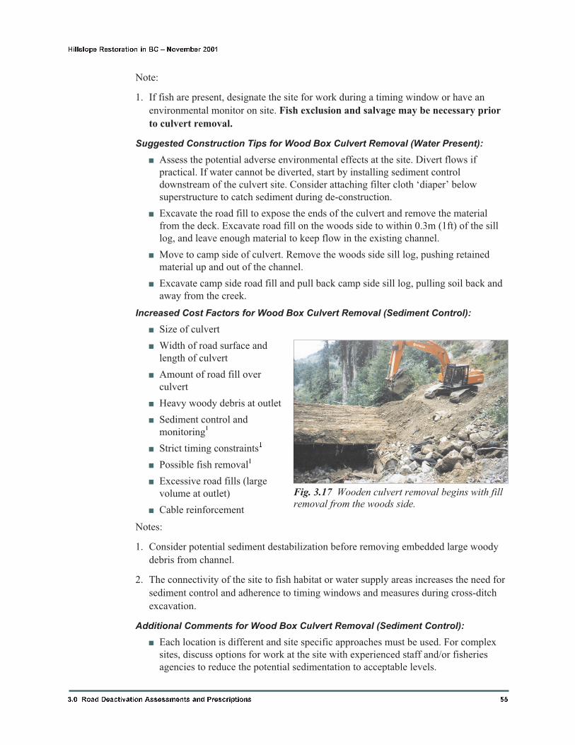
Hillslope Restoration in BC � November 2001
Fig. 3.17 Wooden culvert removal begins with fillremoval from the woods side.
� Methods to make the site as dry as possible may include: diverting water down the
ditch line until the cross-ditch is constructed and armoured; diverting flow using
polyurethane pipe (or similar) using gravity flow; constructing a secondary
cross-ditch in non-erodible materials until the main cross-ditch is complete;
pumping flows around working area (if reliable pump equipment is available).
� The size, depth, and shape of the final cross-ditch depends on the expected flows.
Blend sidewalls of the structure to match adjacent slopes.
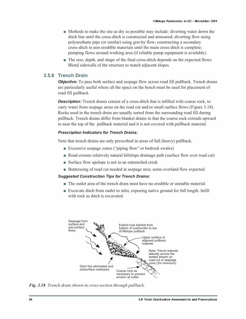
3.5.6 Trench Drain
Objective: To pass both surface and seepage flow across road fill pullback. Trench drains
are particularly useful where all the space on the bench must be used for placement of
road fill pullback.
Description: Trench drains consist of a cross-ditch that is infilled with coarse rock, to
carry water from seepage areas on the road cut and/or small surface flows (Figure 3.18).
Rocks used in the trench drain are usually sorted from the surrounding road fill during
pullback. Trench drains differ from blanket drains in that the coarse rock extends upward
to near the top of the pullback material and it is not covered with pullback material.
Prescription Indicators for Trench Drains:
Note that trench drains are only prescribed in areas of full (heavy) pullback.
� Excessive seepage zones (“piping flow” or bedrock swales)
� Road crosses relatively natural hillslope drainage path (surface flow over road cut)
� Surface flow upslope is not in an entrenched creek
� Buttressing of road cut needed at seepage area; some overland flow expected
Suggested Construction Tips for Trench Drains:
� The outlet area of the trench drain must have no erodible or unstable material.
� Excavate ditch from outlet to inlet, exposing native ground for full length. Infill
with rock as ditch is excavated.
56 3.0 Road Deactivation Assessments and Prescriptions
Hillslope Restoration in BC � November 2001
Seepage fromsurface andsub-surfaceflows.
Ditch line eliminated andsubsurface outsloped.
Extend rock blanket frombottom of overburden to toeof fillslope pullback.
Note: Trench extendslaterally across thewetted stream onroad-cut or seepagezone (3m minimum).
Upper surface ofadjacent pullbackmaterial.
Coarse rock asnecessary to preventerosion at outlet.
Fig. 3.18 Trench drain shown in cross-section through pullback.
� Trench drains must be wider than a cross-ditch to carry the same amount of flow.
� The sorting of the angular rock for the trench drain can be done while pulling back
road fill. A limited amount of soil with the rock is acceptable.
� Place as much material on the woods side of the trench drain before moving to the
camp side.
� Trench drains are infilled with coarse rock and built up as the road fill is pulled
back.
� Double or triple handling coarse rock can help to separate fine soil from coarse rock.
Increased Cost Factors for Trench Drains:
� Amount of road fill to pull back
� Road cut height (height of seepage zone)
� Lack of availability of suitable rock1
� Distance to road cut (width of road)
� Endhauling of road fill pullback material2
� Volume of flow (determines size of armour)3
� Larger size of trench drain (great width and/or depth)
Notes:
1. At locations where the rock for the trench drain is not available, importing rock can
substantially increase the cost.
2. Endhauling of road fill may be necessary where limited space on the bench is
available for placement of road fill pullback.
3. Larger flows will require larger rock for erosion resistance; this larger rock may not
be available in the road fill and may have to be imported.
Additional Comments for Trench Drains:
� If no surface flow is expected, consider using a blanket drain instead of a trench
drain.
� Trench drains must not divert flow onto unstable or erodible slopes.
� Wider trench drains can help disperse the water over a larger hillslope area.
� Consider importing rock for trench drains rather than using an open cross-ditch in
pullback at locations where support is needed to prevent large slumps from the road
cut.
3.5.7 Blanket Drain
Objective: To disperse point seepage or subsurface flow under the road fill pullback.
Blanket drains disperse flow rather than concentrate the flow at one hillslope location.
Blanket drains are not intended to convey surface flow or replace open cross-ditches in
areas of substantial flow.
Description: A blanket drain consists of a layer of cobbles or shot rock placed against
the seepage zone in the road cut. The blanket extends down the cutslope and across the
3.0 Road Deactivation Assessments and Prescriptions 57
Hillslope Restoration in BC � November 2001
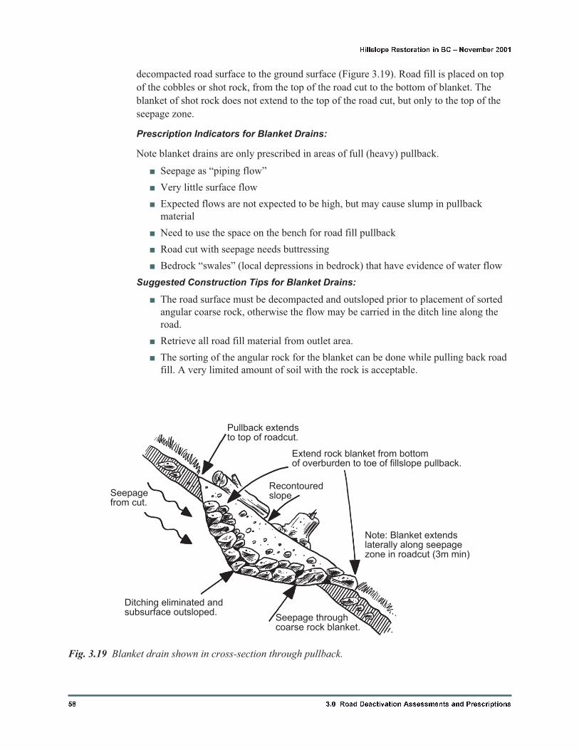
decompacted road surface to the ground surface (Figure 3.19). Road fill is placed on top
of the cobbles or shot rock, from the top of the road cut to the bottom of blanket. The
blanket of shot rock does not extend to the top of the road cut, but only to the top of the
seepage zone.
Prescription Indicators for Blanket Drains:
Note blanket drains are only prescribed in areas of full (heavy) pullback.
� Seepage as “piping flow”
� Very little surface flow
� Expected flows are not expected to be high, but may cause slump in pullback
material
� Need to use the space on the bench for road fill pullback
� Road cut with seepage needs buttressing
� Bedrock “swales” (local depressions in bedrock) that have evidence of water flow
Suggested Construction Tips for Blanket Drains:
� The road surface must be decompacted and outsloped prior to placement of sorted
angular coarse rock, otherwise the flow may be carried in the ditch line along the
road.
� Retrieve all road fill material from outlet area.
� The sorting of the angular rock for the blanket can be done while pulling back road
fill. A very limited amount of soil with the rock is acceptable.
58 3.0 Road Deactivation Assessments and Prescriptions
Hillslope Restoration in BC � November 2001
Pullback extendsto top of roadcut.
Extend rock blanket from bottomof overburden to toe of fillslope pullback.
Note: Blanket extendslaterally along seepagezone in roadcut (3m min)
Seepage throughcoarse rock blanket.
Ditching eliminated andsubsurface outsloped.
Seepagefrom cut.
Recontouredslope
Fig. 3.19 Blanket drain shown in cross-section through pullback.
� Leaving the rock blanket exposed both above and below the pullback should be
done to allow for inspection following the deactivation work.
� “Sprinkling” the rocks on the cutslope and allowing the larger rocks to roll down
the longest distance will create a rock blanket at the road cut and along the
decompacted road surface. Road fill pullback can then be placed on top of the
blanket drain.
Increased Cost Factors for Blanket Drains:
� Larger size of blanket drain (great width and/or depth)
� Road cut height (height of seepage zone)
� Lack of availability of suitable rock1
� Distance to road cut (width of road)
� Endhauling of road fill material2
Notes:
1. At locations where the rock for the blanket drain is not available, importing rock can
substantially increase the cost of blanket drains.
2. Endhauling of road fill may be necessary where limited space on the bench is
available for placement of road fill pullback.
Additional Comments for Blanket Drains:
� If surface flows are expected, consider prescribing a trench drain rather than a
blanket drain.
� Blanket drains will not disperse water along roads with steep road grades; check
outfall location at lower end of blanket drain for stability.
� Less rock can be used if the blanket is covered with geotextile prior to placement of
pullback road fill. If road fill pullback material is fine, erodible soil (silt or fine
sand), use of geotextile will keep the blanket from plugging for a much longer
period of time.
� If the road cut is in fine or erodible soil, the rock blanket may need to be wrapped
entirely in geotextile.
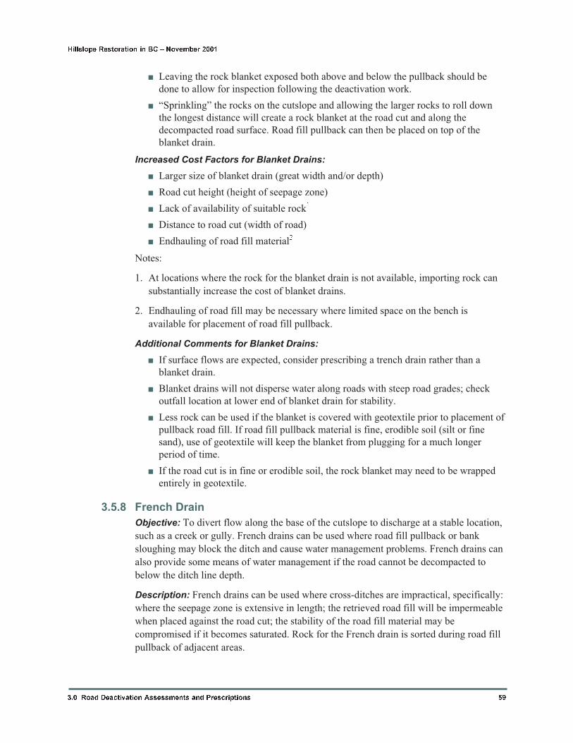
3.5.8 French Drain
Objective: To divert flow along the base of the cutslope to discharge at a stable location,
such as a creek or gully. French drains can be used where road fill pullback or bank
sloughing may block the ditch and cause water management problems. French drains can
also provide some means of water management if the road cannot be decompacted to
below the ditch line depth.
Description: French drains can be used where cross-ditches are impractical, specifically:
where the seepage zone is extensive in length; the retrieved road fill will be impermeable
when placed against the road cut; the stability of the road fill material may be
compromised if it becomes saturated. Rock for the French drain is sorted during road fill
pullback of adjacent areas.
3.0 Road Deactivation Assessments and Prescriptions 59
Hillslope Restoration in BC � November 2001
Prescription Indicators for French Drains:
Note that French drains are normally used in conjunction with road fill pullback, but
sometimes they can be used for active roads with road cut instability.
� Heavy seepage or groundwater piping in road cut (could also use insloping)
� Need to keep water off unstable road fills
� Raveling or sloughing road cuts (allows for buttressing and drainage)
� Where ditch line needs to be maintained under road fill pullback material
Suggested Construction Tips for French Drains:
� The rock must be free draining; geotextile should be used between the drain rock
and soil if the soil is expected to clog the spaces between the rocks.
� The size of the French drain will depend on the width and height of the seepage
zone.
� French drains must not direct flow onto unstable or erodible slopes. Coarse rock
should be placed at the outlet of the French drain to prevent erosion where
necessary.
Increased Cost Factors for French Drains:
� Size of French drain (height, width, depth; determined by size of seepage area)
� Lack of suitable rock nearby1
� No availability of geotextile or slotted pipe (if needed)
� Length of French drain along road cut
� Height of road cut (if French drain is used for buttressing)
� Endhauling of road fill material2
60 3.0 Road Deactivation Assessments and Prescriptions
Hillslope Restoration in BC � November 2001
Seepagefrom cut
Pullbackroadfillmaterial
Ditchlineremains intact
Impermeable barrier(difficult to excavate?)
Subsurfaceflow direction
Longitudinal Frenchdrains release waterinto stable cross-ditches or gullies.
Remove all road fillfrom outlet area.
Road fillpullback
Surface flowdirection incross-ditch orgully channel
Fig. 3.20 French drain shown in cross-section (left) and in oblique view (right).
Notes:
1. At locations where the rock for the French drain
is not available, importing can substantially increase
the cost.
2. Endhauling of road fill may be necessary where
rock is imported and limited space on the bench is
available for placement of road fill pullback.
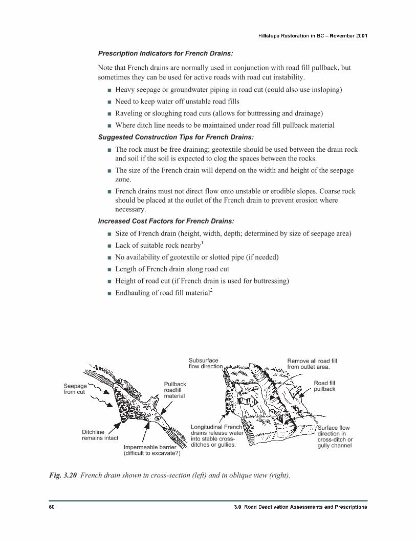
Additional Comments for French Drains:
� In cases where steady flow must be maintained
through the French drain, install a slotted pipe in
the centre of the drain. This system is much more
resistant to clogging than regular coarse rock.
� For active roads, lateral French drains can be
installed in place of culverts to carry seepage
under the road surface (use where culverts are
prone to plugging).
3.0 Road Deactivation Assessments and Prescriptions 61
Hillslope Restoration in BC � November 2001
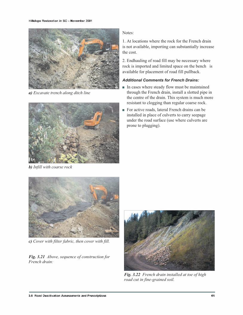
Fig. 3.22 French drain installed at toe of highroad cut in fine-grained soil.
c) Cover with filter fabric, then cover with fill.
b) Infill with coarse rock
a) Excavate trench along ditch line
Fig. 3.21 Above, sequence of construction forFrench drain:
3.5.9 Ford and Armoured Swale
Objective: The main purpose of a ford and armoured swale is to provide an erosion
resistant and storm-proof wet crossing for motor vehicle access. A ford structure is used
to cross a stream, whereas an armoured swale is constructed where a cross-ditch would
normally be used. The reduction of sediment generation and sediment transport during
the intended period of road use is a paramount consideration in the design of both
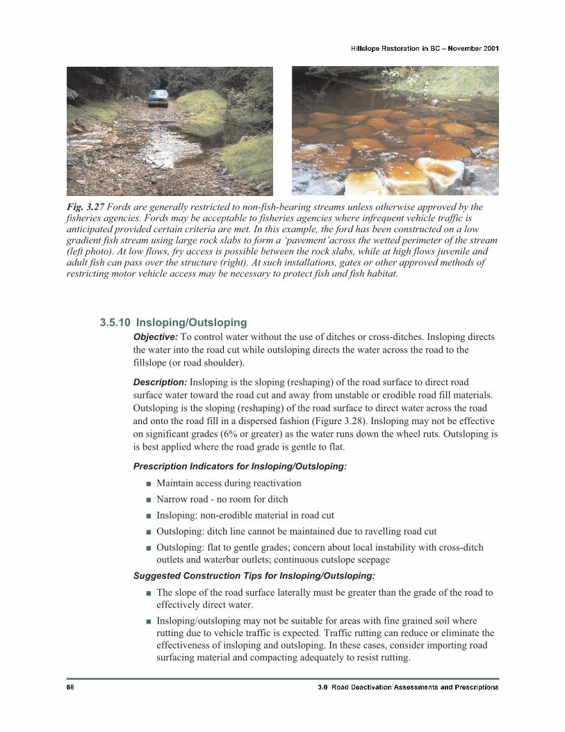
structures. Fords are generally restricted to crossings of non-fish-bearing streams unless
otherwise approved by the fisheries agencies. Armoured swales are intended to route road
surface runoff, ditch water or cut bank seepage across a road where short-term vehicle
access is required. Both may be constructed on access roads where culverts are not
functioning (e.g. washed out or collapsed) and replacement structures not available, or
where seasonal/ephemeral flows may exceed the capacity of the existing culverts during
the time of road use.
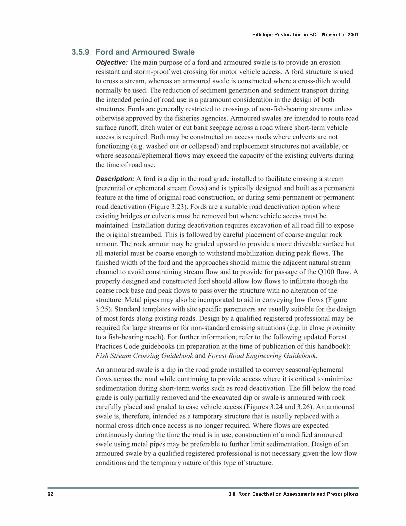
Description: A ford is a dip in the road grade installed to facilitate crossing a stream
(perennial or ephemeral stream flows) and is typically designed and built as a permanent
feature at the time of original road construction, or during semi-permanent or permanent
road deactivation (Figure 3.23). Fords are a suitable road deactivation option where
existing bridges or culverts must be removed but where vehicle access must be
maintained. Installation during deactivation requires excavation of all road fill to expose
the original streambed. This is followed by careful placement of coarse angular rock
armour. The rock armour may be graded upward to provide a more driveable surface but
all material must be coarse enough to withstand mobilization during peak flows. The
finished width of the ford and the approaches should mimic the adjacent natural stream
channel to avoid constraining stream flow and to provide for passage of the Q100 flow. A
properly designed and constructed ford should allow low flows to infiltrate though the
coarse rock base and peak flows to pass over the structure with no alteration of the
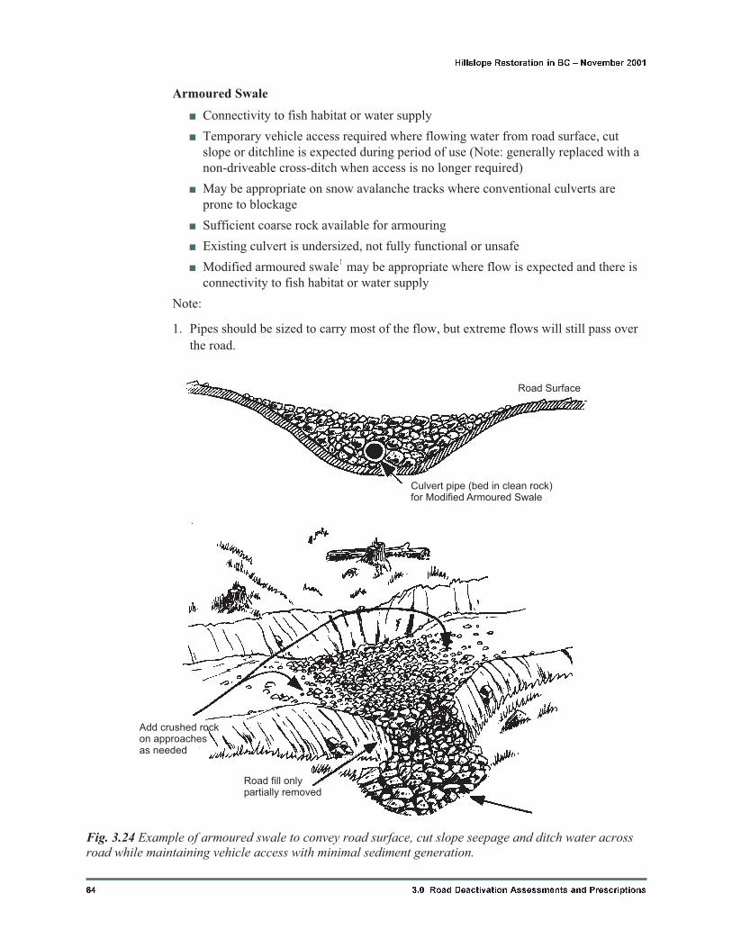
structure. Metal pipes may also be incorporated to aid in conveying low flows (Figure
3.25). Standard templates with site specific parameters are usually suitable for the design
of most fords along existing roads. Design by a qualified registered professional may be
required for large streams or for non-standard crossing situations (e.g. in close proximity
to a fish-bearing reach). For further information, refer to the following updated Forest
Practices Code guidebooks (in preparation at the time of publication of this handbook):
Fish Stream Crossing Guidebook and Forest Road Engineering Guidebook.
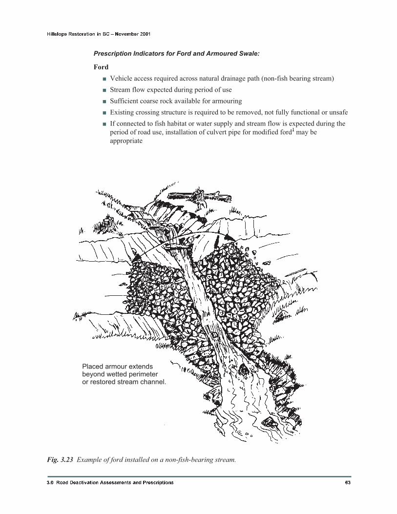
An armoured swale is a dip in the road grade installed to convey seasonal/ephemeral
flows across the road while continuing to provide access where it is critical to minimize
sedimentation during short-term works such as road deactivation. The fill below the road
grade is only partially removed and the excavated dip or swale is armoured with rock
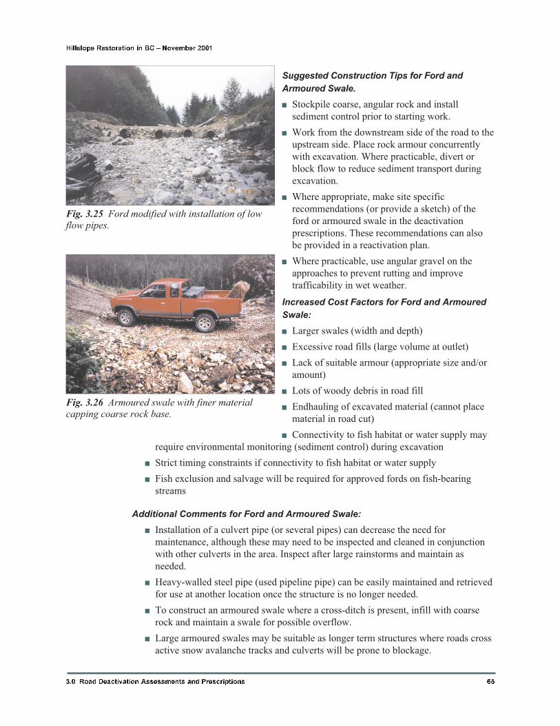
carefully placed and graded to ease vehicle access (Figures 3.24 and 3.26). An armoured
swale is, therefore, intended as a temporary structure that is usually replaced with a
normal cross-ditch once access is no longer required. Where flows are expected
continuously during the time the road is in use, construction of a modified armoured
swale using metal pipes may be preferable to further limit sedimentation. Design of an
armoured swale by a qualified registered professional is not necessary given the low flow
conditions and the temporary nature of this type of structure.
62 3.0 Road Deactivation Assessments and Prescriptions
Hillslope Restoration in BC � November 2001
Prescription Indicators for Ford and Armoured Swale:
Ford
� Vehicle access required across natural drainage path (non-fish bearing stream)
� Stream flow expected during period of use
� Sufficient coarse rock available for armouring
� Existing crossing structure is required to be removed, not fully functional or unsafe
� If connected to fish habitat or water supply and stream flow is expected during the
period of road use, installation of culvert pipe for modified ford1 may be
appropriate
3.0 Road Deactivation Assessments and Prescriptions 63
Hillslope Restoration in BC � November 2001
Placed armour extendsbeyond wetted perimeteror restored stream channel.
Fig. 3.23 Example of ford installed on a non-fish-bearing stream.
Armoured Swale
� Connectivity to fish habitat or water supply
� Temporary vehicle access required where flowing water from road surface, cut
slope or ditchline is expected during period of use (Note: generally replaced with a
non-driveable cross-ditch when access is no longer required)
� May be appropriate on snow avalanche tracks where conventional culverts are
prone to blockage
� Sufficient coarse rock available for armouring
� Existing culvert is undersized, not fully functional or unsafe
� Modified armoured swale1 may be appropriate where flow is expected and there is
connectivity to fish habitat or water supply
Note:
1. Pipes should be sized to carry most of the flow, but extreme flows will still pass over
the road.
64 3.0 Road Deactivation Assessments and Prescriptions
Hillslope Restoration in BC � November 2001
Road Surface
Road fill onlypartially removed
Add crushed rockon approachesas needed
Culvert pipe (bed in clean rock)for Modified Armoured Swale
Fig. 3.24 Example of armoured swale to convey road surface, cut slope seepage and ditch water acrossroad while maintaining vehicle access with minimal sediment generation.
Suggested Construction Tips for Ford and
Armoured Swale.
� Stockpile coarse, angular rock and install
sediment control prior to starting work.
� Work from the downstream side of the road to the
upstream side. Place rock armour concurrently
with excavation. Where practicable, divert or
block flow to reduce sediment transport during
excavation.
� Where appropriate, make site specific
recommendations (or provide a sketch) of the
ford or armoured swale in the deactivation
prescriptions. These recommendations can also
be provided in a reactivation plan.
� Where practicable, use angular gravel on the
approaches to prevent rutting and improve
trafficability in wet weather.
Increased Cost Factors for Ford and Armoured
Swale:
� Larger swales (width and depth)
� Excessive road fills (large volume at outlet)
� Lack of suitable armour (appropriate size and/or
amount)
� Lots of woody debris in road fill
� Endhauling of excavated material (cannot place
material in road cut)
� Connectivity to fish habitat or water supply may
require environmental monitoring (sediment control) during excavation
� Strict timing constraints if connectivity to fish habitat or water supply
� Fish exclusion and salvage will be required for approved fords on fish-bearing
streams
Additional Comments for Ford and Armoured Swale:
� Installation of a culvert pipe (or several pipes) can decrease the need for
maintenance, although these may need to be inspected and cleaned in conjunction
with other culverts in the area. Inspect after large rainstorms and maintain as
needed.
� Heavy-walled steel pipe (used pipeline pipe) can be easily maintained and retrieved
for use at another location once the structure is no longer needed.
� To construct an armoured swale where a cross-ditch is present, infill with coarse
rock and maintain a swale for possible overflow.
� Large armoured swales may be suitable as longer term structures where roads cross
active snow avalanche tracks and culverts will be prone to blockage.
3.0 Road Deactivation Assessments and Prescriptions 65
Hillslope Restoration in BC � November 2001
Fig. 3.25 Ford modified with installation of lowflow pipes.
Fig. 3.26 Armoured swale with finer materialcapping coarse rock base.
3.5.10 Insloping/Outsloping
Objective: To control water without the use of ditches or cross-ditches. Insloping directs
the water into the road cut while outsloping directs the water across the road to the
fillslope (or road shoulder).
Description: Insloping is the sloping (reshaping) of the road surface to direct road
surface water toward the road cut and away from unstable or erodible road fill materials.
Outsloping is the sloping (reshaping) of the road surface to direct water across the road
and onto the road fill in a dispersed fashion (Figure 3.28). Insloping may not be effective
on significant grades (6% or greater) as the water runs down the wheel ruts. Outsloping is
is best applied where the road grade is gentle to flat.
Prescription Indicators for Insloping/Outsloping:
� Maintain access during reactivation
� Narrow road - no room for ditch
� Insloping: non-erodible material in road cut
� Outsloping: ditch line cannot be maintained due to ravelling road cut
� Outsloping: flat to gentle grades; concern about local instability with cross-ditch
outlets and waterbar outlets; continuous cutslope seepage
Suggested Construction Tips for Insloping/Outsloping:
� The slope of the road surface laterally must be greater than the grade of the road to
effectively direct water.
� Insloping/outsloping may not be suitable for areas with fine grained soil where
rutting due to vehicle traffic is expected. Traffic rutting can reduce or eliminate the
effectiveness of insloping and outsloping. In these cases, consider importing road
surfacing material and compacting adequately to resist rutting.
66 3.0 Road Deactivation Assessments and Prescriptions
Hillslope Restoration in BC � November 2001
Fig. 3.27 Fords are generally restricted to non-fish-bearing streams unless otherwise approved by thefisheries agencies. Fords may be acceptable to fisheries agencies where infrequent vehicle traffic isanticipated provided certain criteria are met. In this example, the ford has been constructed on a lowgradient fish stream using large rock slabs to form a ‘pavement’across the wetted perimeter of the stream(left photo). At low flows, fry access is possible between the rock slabs, while at high flows juvenile andadult fish can pass over the structure (right). At such installations, gates or other approved methods ofrestricting motor vehicle access may be necessary to protect fish and fish habitat.
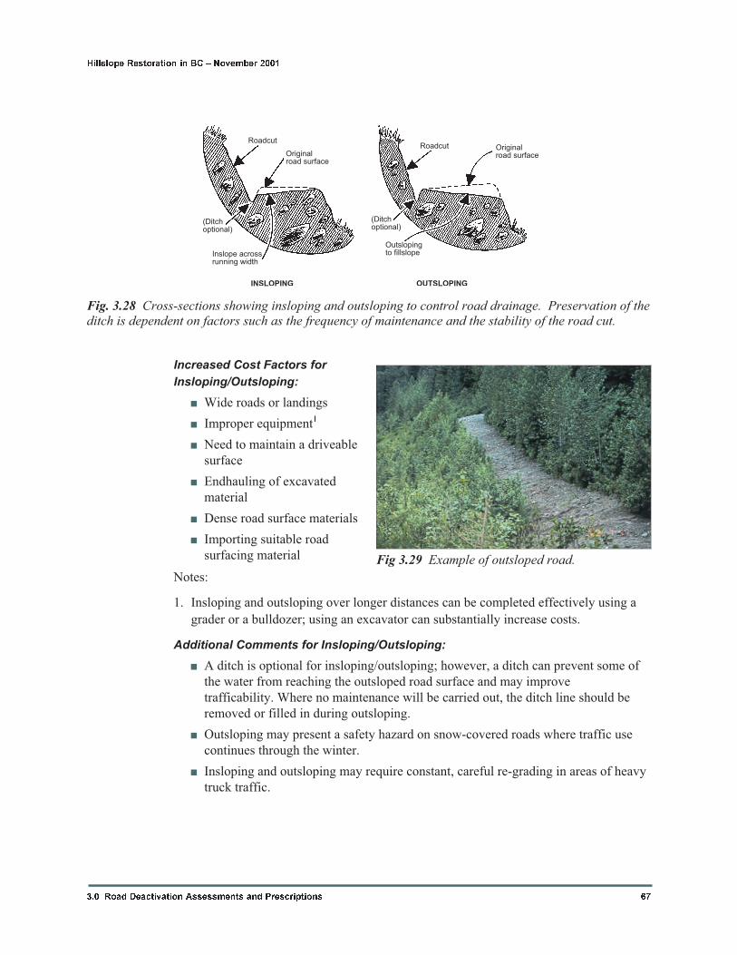
Increased Cost Factors for
Insloping/Outsloping:
� Wide roads or landings
� Improper equipment1
� Need to maintain a driveable
surface
� Endhauling of excavated
material
� Dense road surface materials
� Importing suitable road
surfacing material
Notes:
1. Insloping and outsloping over longer distances can be completed effectively using a
grader or a bulldozer; using an excavator can substantially increase costs.
Additional Comments for Insloping/Outsloping:
� A ditch is optional for insloping/outsloping; however, a ditch can prevent some of
the water from reaching the outsloped road surface and may improve
trafficability. Where no maintenance will be carried out, the ditch line should be
removed or filled in during outsloping.
� Outsloping may present a safety hazard on snow-covered roads where traffic use
continues through the winter.
� Insloping and outsloping may require constant, careful re-grading in areas of heavy
truck traffic.
3.0 Road Deactivation Assessments and Prescriptions 67
Hillslope Restoration in BC � November 2001
Roadcut
Originalroad surface
Originalroad surface
(Ditchoptional)
(Ditchoptional)
Inslope acrossrunning width
INSLOPING
Roadcut
Outslopingto fillslope
OUTSLOPING
Fig. 3.28 Cross-sections showing insloping and outsloping to control road drainage. Preservation of theditch is dependent on factors such as the frequency of maintenance and the stability of the road cut.
Fig 3.29 Example of outsloped road.
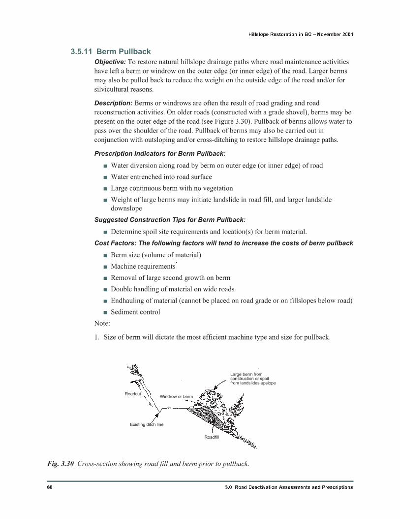
3.5.11 Berm Pullback
Objective: To restore natural hillslope drainage paths where road maintenance activities
have left a berm or windrow on the outer edge (or inner edge) of the road. Larger berms
may also be pulled back to reduce the weight on the outside edge of the road and/or for
silvicultural reasons.
Description: Berms or windrows are often the result of road grading and road
reconstruction activities. On older roads (constructed with a grade shovel), berms may be
present on the outer edge of the road (see Figure 3.30). Pullback of berms allows water to
pass over the shoulder of the road. Pullback of berms may also be carried out in
conjunction with outsloping and/or cross-ditching to restore hillslope drainage paths.
Prescription Indicators for Berm Pullback:
� Water diversion along road by berm on outer edge (or inner edge) of road
� Water entrenched into road surface
� Large continuous berm with no vegetation
� Weight of large berms may initiate landslide in road fill, and larger landslide
downslope
Suggested Construction Tips for Berm Pullback:
� Determine spoil site requirements and location(s) for berm material.
Cost Factors: The following factors will tend to increase the costs of berm pullback
� Berm size (volume of material)
� Machine requirements1
� Removal of large second growth on berm
� Double handling of material on wide roads
� Endhauling of material (cannot be placed on road grade or on fillslopes below road)
� Sediment control
Note:
1. Size of berm will dictate the most efficient machine type and size for pullback.
68 3.0 Road Deactivation Assessments and Prescriptions
Hillslope Restoration in BC � November 2001
Roadcut
Existing ditch line
Windrow or berm
Roadfill
Large berm fromconstruction or spoilfrom landslides upslope
Fig. 3.30 Cross-section showing road fill and berm prior to pullback.
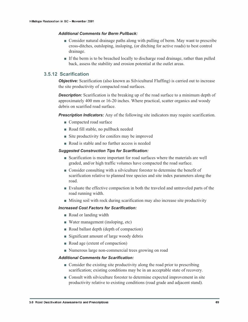
Additional Comments for Berm Pullback:
� Consider natural drainage paths along with pulling of berm. May want to prescribe
cross-ditches, outsloping, insloping, (or ditching for active roads) to best control
drainage.
� If the berm is to be breached locally to discharge road drainage, rather than pulled
back, assess the stability and erosion potential at the outlet areas.
3.5.12 Scarification
Objective: Scarification (also known as Silvicultural Fluffing) is carried out to increase
the site productivity of compacted road surfaces.
Description: Scarification is the breaking up of the road surface to a minimum depth of
approximately 400 mm or 16-20 inches. Where practical, scatter organics and woody
debris on scarified road surface.
Prescription Indicators: Any of the following site indicators may require scarification.
� Compacted road surface
� Road fill stable, no pullback needed
� Site productivity for conifers may be improved
� Road is stable and no further access is needed
Suggested Construction Tips for Scarification:
� Scarification is more important for road surfaces where the materials are well
graded, and/or high traffic volumes have compacted the road surface.
� Consider consulting with a silviculture forester to determine the benefit of
scarification relative to planned tree species and site index parameters along the
road.
� Evaluate the effective compaction in both the traveled and untraveled parts of the
road running width.
� Mixing soil with rock during scarification may also increase site productivity
Increased Cost Factors for Scarification:
� Road or landing width
� Water management (insloping, etc)
� Road ballast depth (depth of compaction)
� Significant amount of large woody debris
� Road age (extent of compaction)
� Numerous large non-commercial trees growing on road
Additional Comments for Scarification:
� Consider the existing site productivity along the road prior to prescribing
scarification; existing conditions may be in an acceptable state of recovery.
� Consult with silviculture forester to determine expected improvement in site
productivity relative to existing conditions (road grade and adjacent stand).
3.0 Road Deactivation Assessments and Prescriptions 69
Hillslope Restoration in BC � November 2001
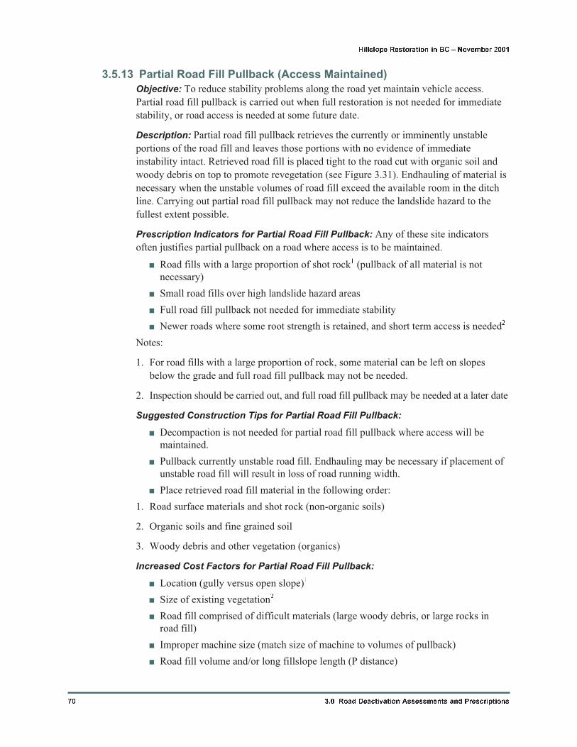
3.5.13 Partial Road Fill Pullback (Access Maintained)
Objective: To reduce stability problems along the road yet maintain vehicle access.
Partial road fill pullback is carried out when full restoration is not needed for immediate
stability, or road access is needed at some future date.
Description: Partial road fill pullback retrieves the currently or imminently unstable
portions of the road fill and leaves those portions with no evidence of immediate
instability intact. Retrieved road fill is placed tight to the road cut with organic soil and
woody debris on top to promote revegetation (see Figure 3.31). Endhauling of material is
necessary when the unstable volumes of road fill exceed the available room in the ditch
line. Carrying out partial road fill pullback may not reduce the landslide hazard to the
fullest extent possible.
Prescription Indicators for Partial Road Fill Pullback: Any of these site indicators
often justifies partial pullback on a road where access is to be maintained.
� Road fills with a large proportion of shot rock1 (pullback of all material is not
necessary)
� Small road fills over high landslide hazard areas
� Full road fill pullback not needed for immediate stability
� Newer roads where some root strength is retained, and short term access is needed2
Notes:
1. For road fills with a large proportion of rock, some material can be left on slopes
below the grade and full road fill pullback may not be needed.
2. Inspection should be carried out, and full road fill pullback may be needed at a later date
Suggested Construction Tips for Partial Road Fill Pullback:
� Decompaction is not needed for partial road fill pullback where access will be
maintained.
� Pullback currently unstable road fill. Endhauling may be necessary if placement of
unstable road fill will result in loss of road running width.
� Place retrieved road fill material in the following order:
1. Road surface materials and shot rock (non-organic soils)
2. Organic soils and fine grained soil
3. Woody debris and other vegetation (organics)
Increased Cost Factors for Partial Road Fill Pullback:
� Location (gully versus open slope)1
� Size of existing vegetation2
� Road fill comprised of difficult materials (large woody debris, or large rocks in
road fill)
� Improper machine size (match size of machine to volumes of pullback)
� Road fill volume and/or long fillslope length (P distance)
70 3.0 Road Deactivation Assessments and Prescriptions
Hillslope Restoration in BC � November 2001
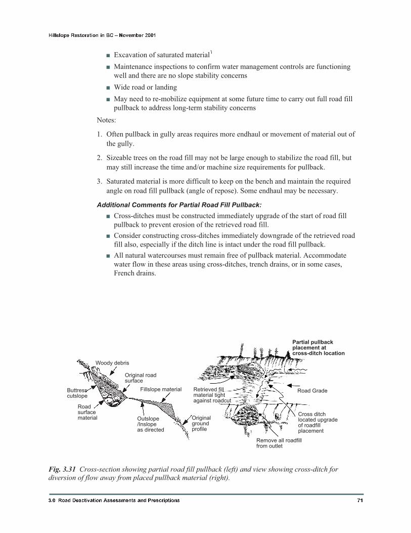
� Excavation of saturated material3
� Maintenance inspections to confirm water management controls are functioning
well and there are no slope stability concerns
� Wide road or landing
� May need to re-mobilize equipment at some future time to carry out full road fill
pullback to address long-term stability concerns
Notes:
1. Often pullback in gully areas requires more endhaul or movement of material out of
the gully.
2. Sizeable trees on the road fill may not be large enough to stabilize the road fill, but
may still increase the time and/or machine size requirements for pullback.
3. Saturated material is more difficult to keep on the bench and maintain the required
angle on road fill pullback (angle of repose). Some endhaul may be necessary.
Additional Comments for Partial Road Fill Pullback:
� Cross-ditches must be constructed immediately upgrade of the start of road fill
pullback to prevent erosion of the retrieved road fill.
� Consider constructing cross-ditches immediately downgrade of the retrieved road
fill also, especially if the ditch line is intact under the road fill pullback.
� All natural watercourses must remain free of pullback material. Accommodate
water flow in these areas using cross-ditches, trench drains, or in some cases,
French drains.
3.0 Road Deactivation Assessments and Prescriptions 71
Hillslope Restoration in BC � November 2001
Retrieved fillmaterial tightagainst roadcut
Remove all roadfillfrom outlet
Cross ditchlocated upgradeof roadfillplacement
Partial pullbackplacement atcross-ditch location
Woody debris
Buttresscutslope
Roadsurfacematerial Outslope
/Inslopeas directed
Originalgroundprofile
Original roadsurface
Fillslope material Road Grade
Fig. 3.31 Cross-section showing partial road fill pullback (left) and view showing cross-ditch fordiversion of flow away from placed pullback material (right).
� Endhauling may not be necessary when continued access is not planned; most
material can be placed directly on the bench.
� If access is required, endhaul requirements can be lessened by placing removed
brush and woody debris back onto the pulled back fillslope. This material will aid
in short-term erosion control as well as enhance soil nutrients. It may be
cost-effective to complete all required pullback for a road section, then replace the
brush and woody debris in conjunction with installation of water management
structures.
� Do not inslope or outslope the road unless specified. Consider decompaction if no
access will be needed following deactivation.
� In some cases, wood box culverts can be left in place if the openings are adequately
sized and they are backed up by adequate cross-ditches.
� If access will not be maintained, consider how stability of the road will deteriorate
over time before concluding that full road fill pullback is not necessary.
� At some sites, partial pullback combined with appropriate water management may
be the most cost-effective means of reducing landslide risk to tolerable levels for
the intended period of continued vehicle access, but future full roadfill pullback
may be needed on steeper slopes to reduce the landslide hazard to tolerable levels.
3.5.14 Full Road Fill Pullback
Objective: To retrieve all potentially unstable sidecast road fill and place it tight against the
road cut. Full road fill pullback reduces the road fill landslide hazard to the fullest extent
possible. Typically, no access or only limited access for foot or ATV traffic is possible after
full road fill pullback has been carried out.
Description: Full road fill pullback, also known as “re-contouring” or “de-building”, is
the de-construction of the road subgrade to restore the original hillslope profile and
contours (Figure 3.34). Full road fill pullback typically involves decompaction and
removal of the road surface to establish safe working areas and increase the downslope
reach of the excavator. Where very long and deep road fills are present, benching and/or
ramping may be needed to adequately retrieve and place all the road fill present (Figure
3.36). In cases where all of the retrieved material cannot be placed on a stable bench,
endhauling may be needed. Woody debris is randomly scattered on the surface of the
pullback material, promoting revegetation and inhibiting deer movement to reduce
browse on seedlings.
Decompaction may be necessary for full road fill pullback (Figure 3.34) especially in
areas of heavy seapage. Decompaction is the breaking up of road fill materials (ballast
and subgrade) to a depth equal to, or greater than, the depth of the ditch and removing the
material. The decompacted surface is outsloped, to provide better downslope reach and
promote water flow across the road under the pullback material. Decompaction of the
road fill can also define the width of the natural bench so that a safe working limit for the
excavator can be established.
Prescription Indicators for Full Road Fill Pullback: Any of these site observations is
often an indicator that full road fill pullback is needed. Consider both the landslide hazard
and the risk to downslope/downstream resources when deciding whether full road fill
pullback is needed.
72 3.0 Road Deactivation Assessments and Prescriptions
Hillslope Restoration in BC � November 2001
� Landslides from road fill in adjacent areas
� Large retrogressive landslides in road cut
� Tension cracks in road (not settlement cracks)1
� Sidecast construction with high road cut
� Pistol-butted trees or jackstrawed (tilted) trees on road fill
� Narrow roads and high cutslopes on steep slopes
� Road fill supported by stumps and other woody debris; abundant large woody
debris in road fill
� Road fill settlement above steep, unstable areas; repeated filling and grading of road
fill areas
Notes:
1. Settlement from decomposing wood may not be a stability problem on gentle to flat
hillslopes, but may be a safety problem for vehicle traffic or hauling activities.
Suggested Construction Tips for Full Road Fill Pullback:
� Walk site to evaluate safety concerns prior to starting road fill pullback. If a safe
approach is not apparent, ask for help.
� Prior to starting pullback at the station, visualize the ground profile and contours
above and below the road.
� As appropriate, decompact and remove the road surface to a depth below the ditch
line. Sitting the excavator on the lowered (decompacted) surface will extend the
effective reach of the excavator during pullback. Note that decompaction may not
be possible in areas where a portion of the road bench is blasted into solid bedrock.
In this case, complete fill retrieval may not be possible. Consider using a log to
push any residual unstable fill downslope. It may be preferable to unload this
material in a controlled manner during dry conditions, rather than have it fail during
wet conditions.
� Retrieve all fill to expose native material.
� Place road fill material tight to the road cut. During road fill pullback in rocky
materials, releasing material above the slope and letting the rocks roll down to the
bench can often create a blanket drain.
� Place retrieved road fill material in the following order; see sketch below.
� Road surface materials and shot rock (non-organic soils)
� Organic soils and fine grained soil
� Woody debris and other vegetation (organics)
� Benching-Ramping may be necessary in areas where unstable road fill is present
beyond the reach of the excavator. An example of the steps for benching and
ramping is shown in Figure 3.36.
� Step 1 establishes a bench that is wider and lower than the existing road grade,
increasing machine reach. Additional benching may be necessary to retrieve all
unstable fill. Benching must only be done by experienced operators, only into
native ground with an escape route available at all times.
3.0 Road Deactivation Assessments and Prescriptions 73
Hillslope Restoration in BC � November 2001
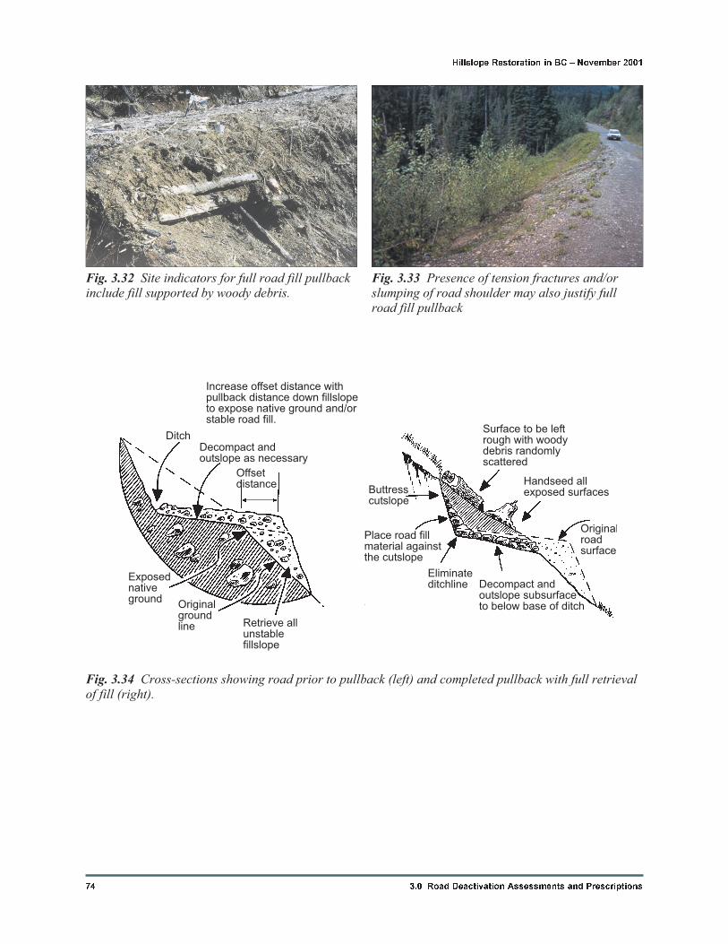
74 3.0 Road Deactivation Assessments and Prescriptions
Hillslope Restoration in BC � November 2001
Surface to be leftrough with woodydebris randomlyscattered
Handseed allexposed surfaces
Originalroadsurface
Decompact andoutslope subsurfaceto below base of ditch
Eliminateditchline
Place road fillmaterial againstthe cutslope
Buttresscutslope
DitchDecompact andoutslope as necessary
Increase offset distance withpullback distance down fillslopeto expose native ground and/orstable road fill.
Retrieve allunstablefillslope
Originalgroundline
Exposednativeground
Offsetdistance
Fig. 3.34 Cross-sections showing road prior to pullback (left) and completed pullback with full retrievalof fill (right).
Fig. 3.32 Site indicators for full road fill pullbackinclude fill supported by woody debris.
Fig. 3.33 Presence of tension fractures and/orslumping of road shoulder may also justify fullroad fill pullback
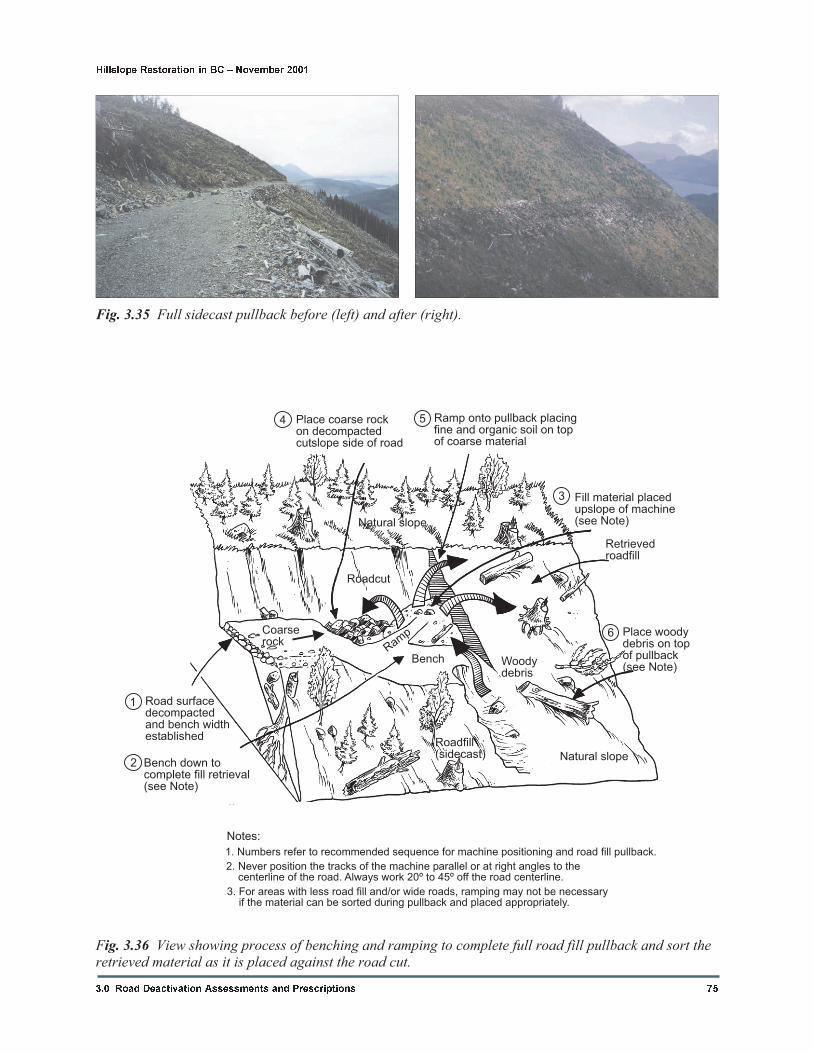
3.0 Road Deactivation Assessments and Prescriptions 75
Hillslope Restoration in BC � November 2001
Fig. 3.35 Full sidecast pullback before (left) and after (right).
Place coarse rockon decompactedcutslope side of road
Ramp onto pullback placingfine and organic soil on topof coarse material
Fill material placedupslope of machine(see Note)
Retrievedroadfill
Place woodydebris on topof pullback(see Note)
Natural slope
Natural slope
Roadfill(sidecast)
BenchRam
pCoarserock
Bench down tocomplete fill retrieval(see Note)
Road surfacedecompactedand bench widthestablished
Roadcut
Notes:
Woodydebris
1
2
3
54
6
Fig. 3.36 View showing process of benching and ramping to complete full road fill pullback and sort theretrieved material as it is placed against the road cut.
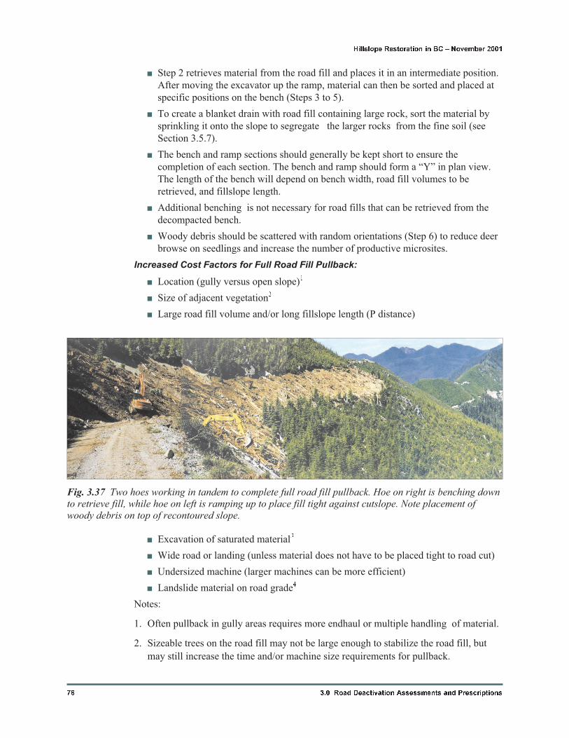
� Step 2 retrieves material from the road fill and places it in an intermediate position.
After moving the excavator up the ramp, material can then be sorted and placed at
specific positions on the bench (Steps 3 to 5).
� To create a blanket drain with road fill containing large rock, sort the material by
sprinkling it onto the slope to segregate the larger rocks from the fine soil (see
Section 3.5.7).
� The bench and ramp sections should generally be kept short to ensure the
completion of each section. The bench and ramp should form a “Y” in plan view.
The length of the bench will depend on bench width, road fill volumes to be
retrieved, and fillslope length.
� Additional benching is not necessary for road fills that can be retrieved from the
decompacted bench.
� Woody debris should be scattered with random orientations (Step 6) to reduce deer
browse on seedlings and increase the number of productive microsites.
Increased Cost Factors for Full Road Fill Pullback:
� Location (gully versus open slope)1
� Size of adjacent vegetation2
� Large road fill volume and/or long fillslope length (P distance)
� Excavation of saturated material3
� Wide road or landing (unless material does not have to be placed tight to road cut)
� Undersized machine (larger machines can be more efficient)
� Landslide material on road grade4
Notes:
1. Often pullback in gully areas requires more endhaul or multiple handling of material.
2. Sizeable trees on the road fill may not be large enough to stabilize the road fill, but
may still increase the time and/or machine size requirements for pullback.
76 3.0 Road Deactivation Assessments and Prescriptions
Hillslope Restoration in BC � November 2001
Fig. 3.37 Two hoes working in tandem to complete full road fill pullback. Hoe on right is benching downto retrieve fill, while hoe on left is ramping up to place fill tight against cutslope. Note placement ofwoody debris on top of recontoured slope.
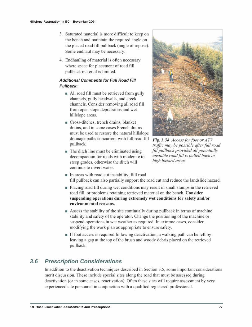
3. Saturated material is more difficult to keep on
the bench and maintain the required angle on
the placed road fill pullback (angle of repose).
Some endhaul may be necessary.
4. Endhauling of material is often necessary
where space for placement of road fill
pullback material is limited.
Additional Comments for Full Road Fill
Pullback:
� All road fill must be retrieved from gully
channels, gully headwalls, and creek
channels. Consider removing all road fill
from open slope depressions and wet
hillslope areas.
� Cross-ditches, trench drains, blanket
drains, and in some cases French drains
must be used to restore the natural hillslope
drainage paths concurrent with full road fill
pullback.
� The ditch line must be eliminated using
decompaction for roads with moderate to
steep grades, otherwise the ditch will
continue to divert water.
� In areas with road cut instability, full road
fill pullback can also partially support the road cut and reduce the landslide hazard.
� Placing road fill during wet conditions may result in small slumps in the retrieved
road fill, or problems retaining retrieved material on the bench. Consider
suspending operations during extremely wet conditions for safety and/or
environmental reasons.
� Assess the stability of the site continually during pullback in terms of machine
stability and safety of the operator. Change the positioning of the machine or
suspend operations in wet weather as required. In extreme cases, consider
modifying the work plan as appropriate to ensure safety.
� If foot access is required following deactivation, a walking path can be left by
leaving a gap at the top of the brush and woody debris placed on the retrieved
pullback.
3.6 Prescription Considerations
In addition to the deactivation techniques described in Section 3.5, some important considerations
merit discussion. These include special sites along the road that must be assessed during
deactivation (or in some cases, reactivation). Often these sites will require assessment by very
experienced site personnel in conjunction with a qualified registered professional.
3.0 Road Deactivation Assessments and Prescriptions 77
Hillslope Restoration in BC � November 2001
Fig. 3.38 Access for foot or ATVtraffic may be possible after full roadfill pullback provided all potentiallyunstable road fill is pulled back inhigh hazard areas.
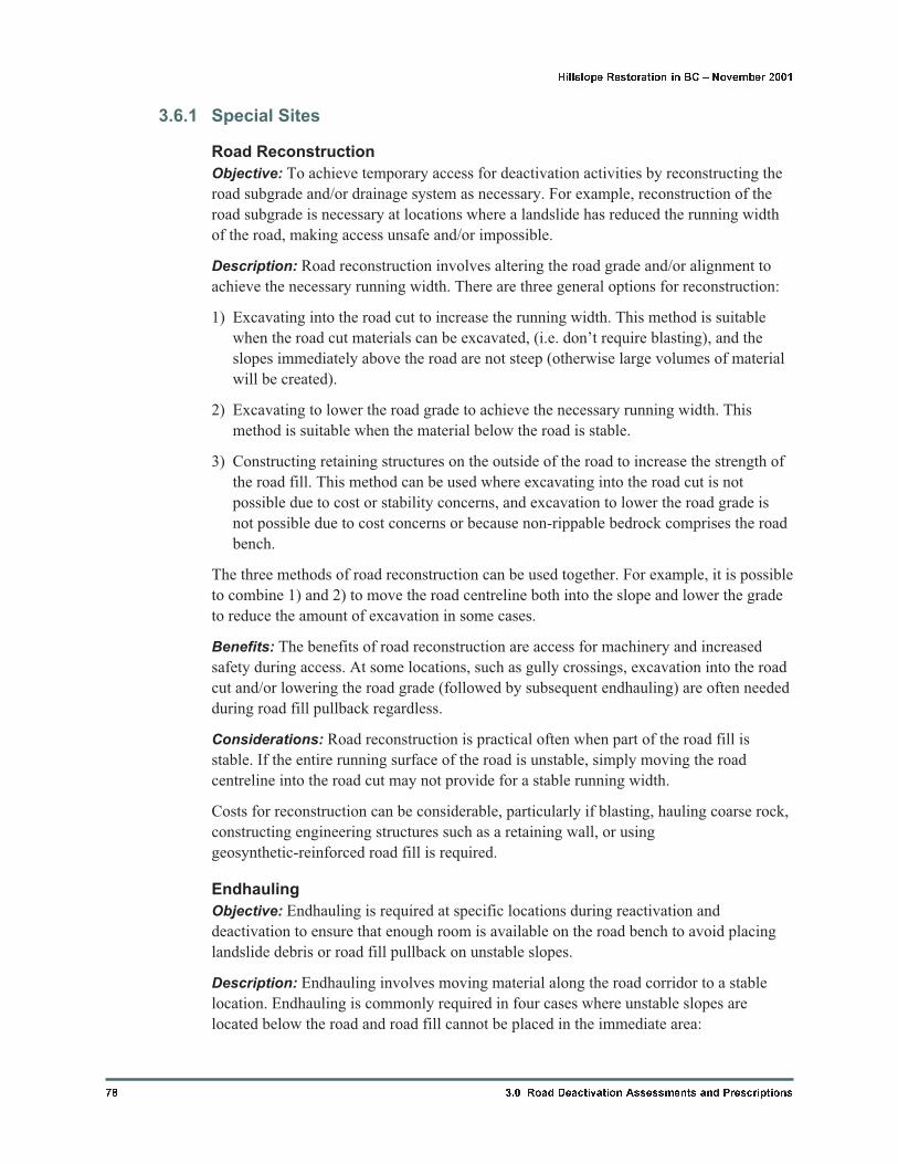
3.6.1 Special Sites
Road Reconstruction
Objective: To achieve temporary access for deactivation activities by reconstructing the
road subgrade and/or drainage system as necessary. For example, reconstruction of the
road subgrade is necessary at locations where a landslide has reduced the running width
of the road, making access unsafe and/or impossible.
Description: Road reconstruction involves altering the road grade and/or alignment to
achieve the necessary running width. There are three general options for reconstruction:
1) Excavating into the road cut to increase the running width. This method is suitable
when the road cut materials can be excavated, (i.e. don’t require blasting), and the
slopes immediately above the road are not steep (otherwise large volumes of material
will be created).
2) Excavating to lower the road grade to achieve the necessary running width. This
method is suitable when the material below the road is stable.
3) Constructing retaining structures on the outside of the road to increase the strength of
the road fill. This method can be used where excavating into the road cut is not
possible due to cost or stability concerns, and excavation to lower the road grade is
not possible due to cost concerns or because non-rippable bedrock comprises the road
bench.
The three methods of road reconstruction can be used together. For example, it is possible
to combine 1) and 2) to move the road centreline both into the slope and lower the grade
to reduce the amount of excavation in some cases.
Benefits: The benefits of road reconstruction are access for machinery and increased
safety during access. At some locations, such as gully crossings, excavation into the road
cut and/or lowering the road grade (followed by subsequent endhauling) are often needed
during road fill pullback regardless.
Considerations: Road reconstruction is practical often when part of the road fill is
stable. If the entire running surface of the road is unstable, simply moving the road
centreline into the road cut may not provide for a stable running width.
Costs for reconstruction can be considerable, particularly if blasting, hauling coarse rock,
constructing engineering structures such as a retaining wall, or using
geosynthetic-reinforced road fill is required.
Endhauling
Objective: Endhauling is required at specific locations during reactivation and
deactivation to ensure that enough room is available on the road bench to avoid placing
landslide debris or road fill pullback on unstable slopes.
Description: Endhauling involves moving material along the road corridor to a stable
location. Endhauling is commonly required in four cases where unstable slopes are
located below the road and road fill cannot be placed in the immediate area:
78 3.0 Road Deactivation Assessments and Prescriptions
Hillslope Restoration in BC � November 2001
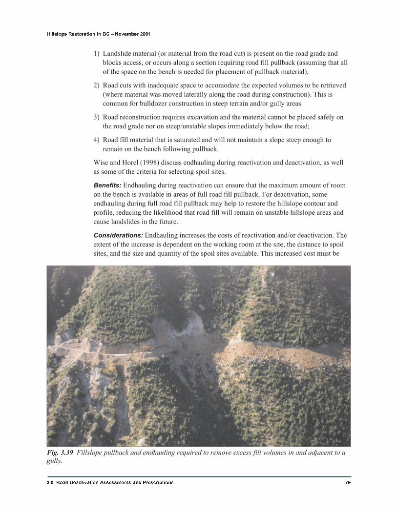
1) Landslide material (or material from the road cut) is present on the road grade and
blocks access, or occurs along a section requiring road fill pullback (assuming that all
of the space on the bench is needed for placement of pullback material);
2) Road cuts with inadequate space to accomodate the expected volumes to be retrieved
(where material was moved laterally along the road during construction). This is
common for bulldozer construction in steep terrain and/or gully areas.
3) Road reconstruction requires excavation and the material cannot be placed safely on
the road grade nor on steep/unstable slopes immediately below the road;
4) Road fill material that is saturated and will not maintain a slope steep enough to
remain on the bench following pullback.
Wise and Horel (1998) discuss endhauling during reactivation and deactivation, as well
as some of the criteria for selecting spoil sites.
Benefits: Endhauling during reactivation can ensure that the maximum amount of room
on the bench is available in areas of full road fill pullback. For deactivation, some
endhauling during full road fill pullback may help to restore the hillslope contour and
profile, reducing the likelihood that road fill will remain on unstable hillslope areas and
cause landslides in the future.
Considerations: Endhauling increases the costs of reactivation and/or deactivation. The
extent of the increase is dependent on the working room at the site, the distance to spoil
sites, and the size and quantity of the spoil sites available. This increased cost must be
3.0 Road Deactivation Assessments and Prescriptions 79
Hillslope Restoration in BC � November 2001
Fig. 3.39 Fillslope pullback and endhauling required to remove excess fill volumes in and adjacent to agully.
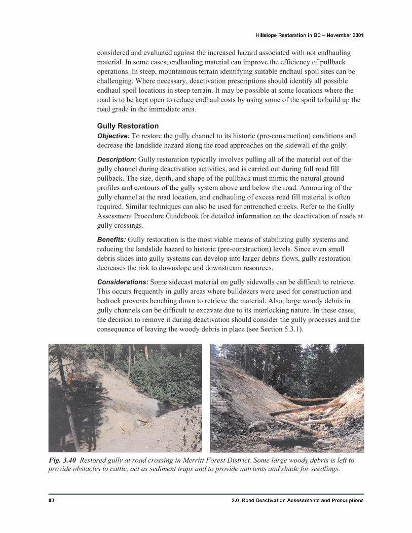
considered and evaluated against the increased hazard associated with not endhauling
material. In some cases, endhauling material can improve the efficiency of pullback
operations. In steep, mountainous terrain identifying suitable endhaul spoil sites can be
challenging. Where necessary, deactivation prescriptions should identify all possible
endhaul spoil locations in steep terrain. It may be possible at some locations where the
road is to be kept open to reduce endhaul costs by using some of the spoil to build up the
road grade in the immediate area.
Gully Restoration
Objective: To restore the gully channel to its historic (pre-construction) conditions and
decrease the landslide hazard along the road approaches on the sidewall of the gully.
Description: Gully restoration typically involves pulling all of the material out of the
gully channel during deactivation activities, and is carried out during full road fill
pullback. The size, depth, and shape of the pullback must mimic the natural ground
profiles and contours of the gully system above and below the road. Armouring of the
gully channel at the road location, and endhauling of excess road fill material is often
required. Similar techniques can also be used for entrenched creeks. Refer to the Gully
Assessment Procedure Guidebook for detailed information on the deactivation of roads at
gully crossings.
Benefits: Gully restoration is the most viable means of stabilizing gully systems and
reducing the landslide hazard to historic (pre-construction) levels. Since even small
debris slides into gully systems can develop into larger debris flows, gully restoration
decreases the risk to downslope and downstream resources.
Considerations: Some sidecast material on gully sidewalls can be difficult to retrieve.
This occurs frequently in gully areas where bulldozers were used for construction and
bedrock prevents benching down to retrieve the material. Also, large woody debris in
gully channels can be difficult to excavate due to its interlocking nature. In these cases,
the decision to remove it during deactivation should consider the gully processes and the
consequence of leaving the woody debris in place (see Section 5.3.1).
80 3.0 Road Deactivation Assessments and Prescriptions
Hillslope Restoration in BC � November 2001
Fig. 3.40 Restored gully at road crossing in Merritt Forest District. Some large woody debris is left toprovide obstacles to cattle, act as sediment traps and to provide nutrients and shade for seedlings.
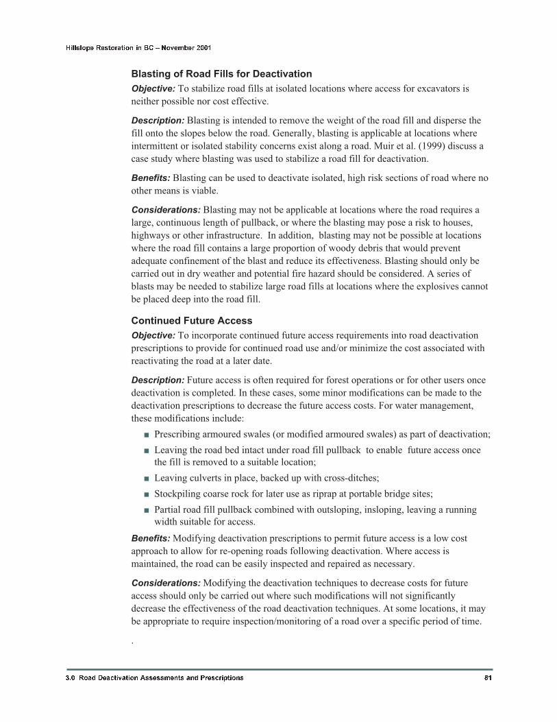
Blasting of Road Fills for Deactivation
Objective: To stabilize road fills at isolated locations where access for excavators is
neither possible nor cost effective.
Description: Blasting is intended to remove the weight of the road fill and disperse the
fill onto the slopes below the road. Generally, blasting is applicable at locations where
intermittent or isolated stability concerns exist along a road. Muir et al. (1999) discuss a
case study where blasting was used to stabilize a road fill for deactivation.
Benefits: Blasting can be used to deactivate isolated, high risk sections of road where no
other means is viable.
Considerations: Blasting may not be applicable at locations where the road requires a
large, continuous length of pullback, or where the blasting may pose a risk to houses,
highways or other infrastructure. In addition, blasting may not be possible at locations
where the road fill contains a large proportion of woody debris that would prevent
adequate confinement of the blast and reduce its effectiveness. Blasting should only be
carried out in dry weather and potential fire hazard should be considered. A series of
blasts may be needed to stabilize large road fills at locations where the explosives cannot
be placed deep into the road fill.
Continued Future Access
Objective: To incorporate continued future access requirements into road deactivation
prescriptions to provide for continued road use and/or minimize the cost associated with
reactivating the road at a later date.
Description: Future access is often required for forest operations or for other users once
deactivation is completed. In these cases, some minor modifications can be made to the
deactivation prescriptions to decrease the future access costs. For water management,
these modifications include:
� Prescribing armoured swales (or modified armoured swales) as part of deactivation;
� Leaving the road bed intact under road fill pullback to enable future access once
the fill is removed to a suitable location;
� Leaving culverts in place, backed up with cross-ditches;
� Stockpiling coarse rock for later use as riprap at portable bridge sites;
� Partial road fill pullback combined with outsloping, insloping, leaving a running
width suitable for access.
Benefits: Modifying deactivation prescriptions to permit future access is a low cost
approach to allow for re-opening roads following deactivation. Where access is
maintained, the road can be easily inspected and repaired as necessary.
Considerations: Modifying the deactivation techniques to decrease costs for future
access should only be carried out where such modifications will not significantly
decrease the effectiveness of the road deactivation techniques. At some locations, it may
be appropriate to require inspection/monitoring of a road over a specific period of time.
.
3.0 Road Deactivation Assessments and Prescriptions 81
Hillslope Restoration in BC � November 2001
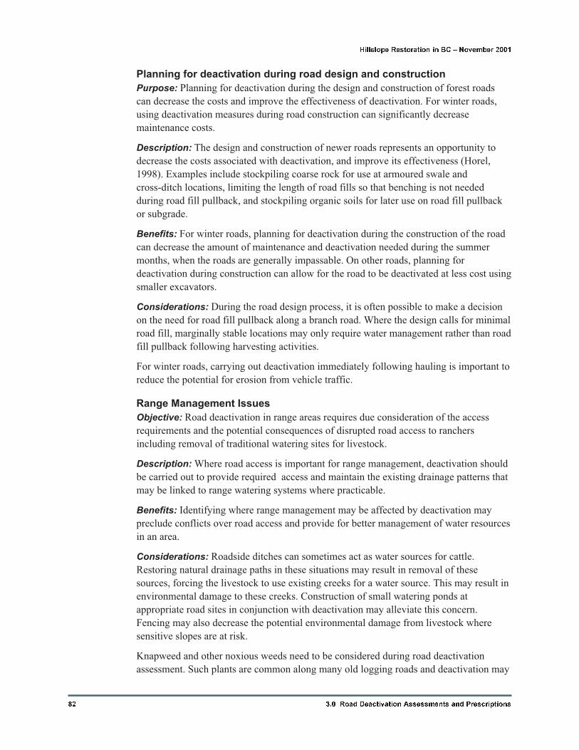
Planning for deactivation during road design and construction
Purpose: Planning for deactivation during the design and construction of forest roads
can decrease the costs and improve the effectiveness of deactivation. For winter roads,
using deactivation measures during road construction can significantly decrease
maintenance costs.
Description: The design and construction of newer roads represents an opportunity to
decrease the costs associated with deactivation, and improve its effectiveness (Horel,
1998). Examples include stockpiling coarse rock for use at armoured swale and
cross-ditch locations, limiting the length of road fills so that benching is not needed
during road fill pullback, and stockpiling organic soils for later use on road fill pullback
or subgrade.
Benefits: For winter roads, planning for deactivation during the construction of the road
can decrease the amount of maintenance and deactivation needed during the summer
months, when the roads are generally impassable. On other roads, planning for
deactivation during construction can allow for the road to be deactivated at less cost using
smaller excavators.
Considerations: During the road design process, it is often possible to make a decision
on the need for road fill pullback along a branch road. Where the design calls for minimal
road fill, marginally stable locations may only require water management rather than road
fill pullback following harvesting activities.
For winter roads, carrying out deactivation immediately following hauling is important to
reduce the potential for erosion from vehicle traffic.
Range Management Issues
Objective: Road deactivation in range areas requires due consideration of the access
requirements and the potential consequences of disrupted road access to ranchers
including removal of traditional watering sites for livestock.
Description: Where road access is important for range management, deactivation should
be carried out to provide required access and maintain the existing drainage patterns that
may be linked to range watering systems where practicable.
Benefits: Identifying where range management may be affected by deactivation may
preclude conflicts over road access and provide for better management of water resources
in an area.
Considerations: Roadside ditches can sometimes act as water sources for cattle.
Restoring natural drainage paths in these situations may result in removal of these
sources, forcing the livestock to use existing creeks for a water source. This may result in
environmental damage to these creeks. Construction of small watering ponds at
appropriate road sites in conjunction with deactivation may alleviate this concern.
Fencing may also decrease the potential environmental damage from livestock where
sensitive slopes are at risk.
Knapweed and other noxious weeds need to be considered during road deactivation
assessment. Such plants are common along many old logging roads and deactivation may
82 3.0 Road Deactivation Assessments and Prescriptions
Hillslope Restoration in BC � November 2001
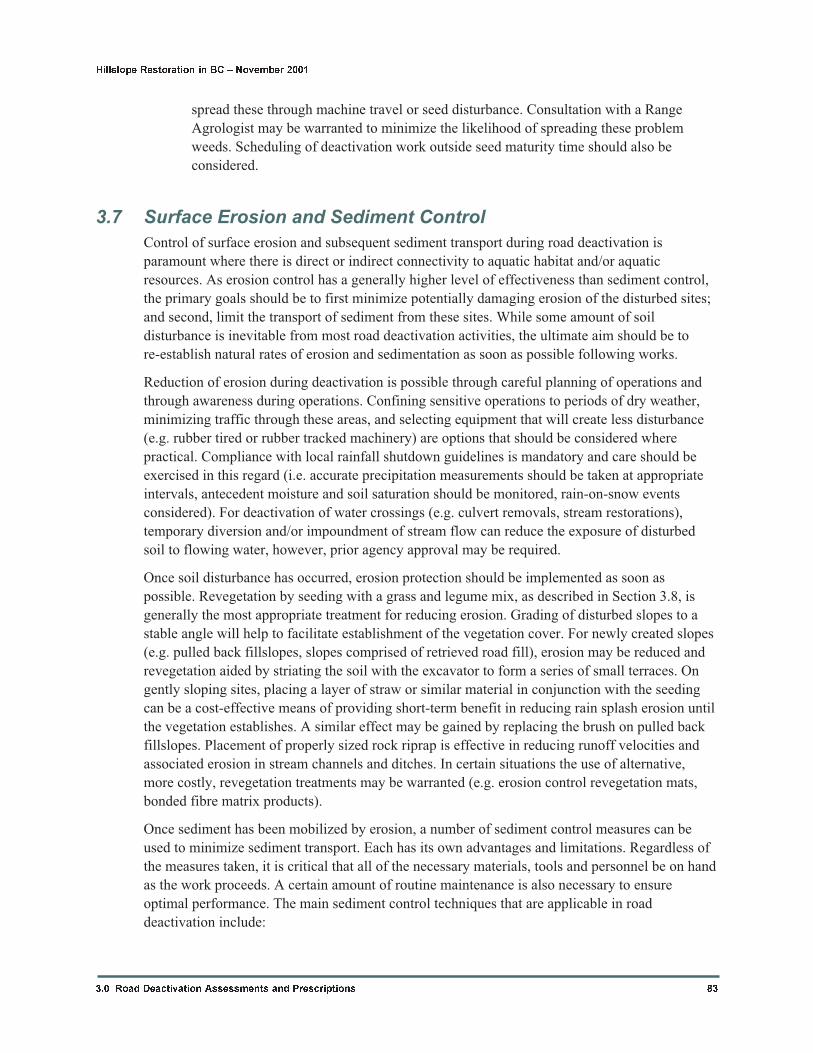
spread these through machine travel or seed disturbance. Consultation with a Range
Agrologist may be warranted to minimize the likelihood of spreading these problem
weeds. Scheduling of deactivation work outside seed maturity time should also be
considered.
3.7 Surface Erosion and Sediment Control
Control of surface erosion and subsequent sediment transport during road deactivation is
paramount where there is direct or indirect connectivity to aquatic habitat and/or aquatic
resources. As erosion control has a generally higher level of effectiveness than sediment control,
the primary goals should be to first minimize potentially damaging erosion of the disturbed sites;
and second, limit the transport of sediment from these sites. While some amount of soil
disturbance is inevitable from most road deactivation activities, the ultimate aim should be to
re-establish natural rates of erosion and sedimentation as soon as possible following works.
Reduction of erosion during deactivation is possible through careful planning of operations and
through awareness during operations. Confining sensitive operations to periods of dry weather,
minimizing traffic through these areas, and selecting equipment that will create less disturbance
(e.g. rubber tired or rubber tracked machinery) are options that should be considered where
practical. Compliance with local rainfall shutdown guidelines is mandatory and care should be
exercised in this regard (i.e. accurate precipitation measurements should be taken at appropriate
intervals, antecedent moisture and soil saturation should be monitored, rain-on-snow events
considered). For deactivation of water crossings (e.g. culvert removals, stream restorations),
temporary diversion and/or impoundment of stream flow can reduce the exposure of disturbed
soil to flowing water, however, prior agency approval may be required.
Once soil disturbance has occurred, erosion protection should be implemented as soon as
possible. Revegetation by seeding with a grass and legume mix, as described in Section 3.8, is
generally the most appropriate treatment for reducing erosion. Grading of disturbed slopes to a
stable angle will help to facilitate establishment of the vegetation cover. For newly created slopes
(e.g. pulled back fillslopes, slopes comprised of retrieved road fill), erosion may be reduced and
revegetation aided by striating the soil with the excavator to form a series of small terraces. On
gently sloping sites, placing a layer of straw or similar material in conjunction with the seeding
can be a cost-effective means of providing short-term benefit in reducing rain splash erosion until
the vegetation establishes. A similar effect may be gained by replacing the brush on pulled back
fillslopes. Placement of properly sized rock riprap is effective in reducing runoff velocities and
associated erosion in stream channels and ditches. In certain situations the use of alternative,
more costly, revegetation treatments may be warranted (e.g. erosion control revegetation mats,
bonded fibre matrix products).
Once sediment has been mobilized by erosion, a number of sediment control measures can be
used to minimize sediment transport. Each has its own advantages and limitations. Regardless of
the measures taken, it is critical that all of the necessary materials, tools and personnel be on hand
as the work proceeds. A certain amount of routine maintenance is also necessary to ensure
optimal performance. The main sediment control techniques that are applicable in road
deactivation include:
3.0 Road Deactivation Assessments and Prescriptions 83
Hillslope Restoration in BC � November 2001
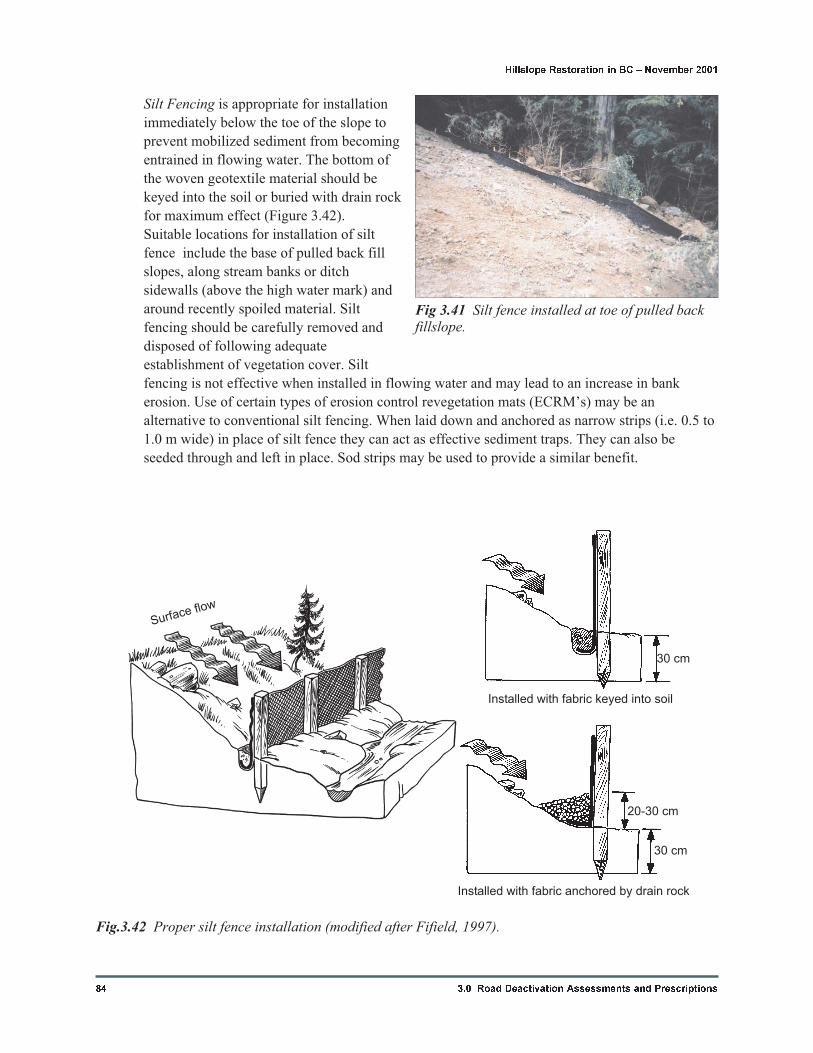
Silt Fencing is appropriate for installation
immediately below the toe of the slope to
prevent mobilized sediment from becoming
entrained in flowing water. The bottom of
the woven geotextile material should be
keyed into the soil or buried with drain rock
for maximum effect (Figure 3.42).
Suitable locations for installation of silt
fence include the base of pulled back fill
slopes, along stream banks or ditch
sidewalls (above the high water mark) and
around recently spoiled material. Silt
fencing should be carefully removed and
disposed of following adequate
establishment of vegetation cover. Silt
fencing is not effective when installed in flowing water and may lead to an increase in bank
erosion. Use of certain types of erosion control revegetation mats (ECRM’s) may be an
alternative to conventional silt fencing. When laid down and anchored as narrow strips (i.e. 0.5 to
1.0 m wide) in place of silt fence they can act as effective sediment traps. They can also be
seeded through and left in place. Sod strips may be used to provide a similar benefit.
84 3.0 Road Deactivation Assessments and Prescriptions
Hillslope Restoration in BC � November 2001
Fig 3.41 Silt fence installed at toe of pulled backfillslope.
Surface flow
30 cm
20-30 cm
30 cm
Installed with fabric keyed into soil
Installed with fabric anchored by drain rock
Fig.3.42 Proper silt fence installation (modified after Fifield, 1997).
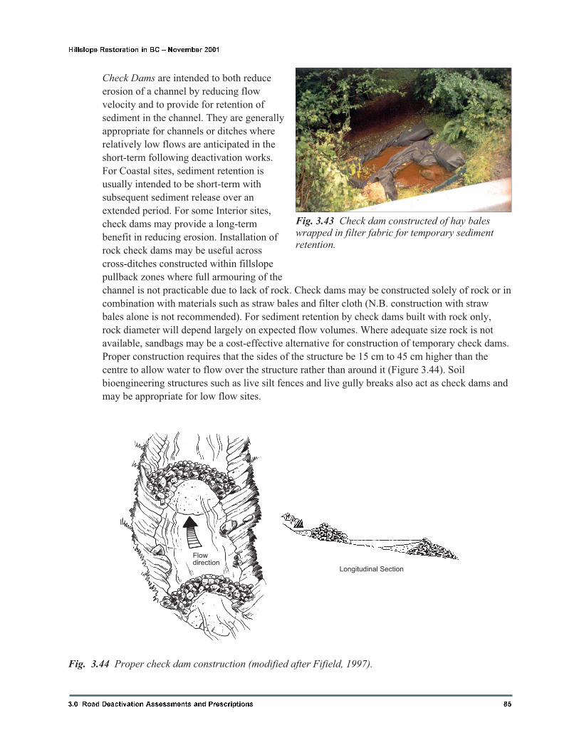
Check Dams are intended to both reduce
erosion of a channel by reducing flow
velocity and to provide for retention of
sediment in the channel. They are generally
appropriate for channels or ditches where
relatively low flows are anticipated in the
short-term following deactivation works.
For Coastal sites, sediment retention is
usually intended to be short-term with
subsequent sediment release over an
extended period. For some Interior sites,
check dams may provide a long-term
benefit in reducing erosion. Installation of
rock check dams may be useful across
cross-ditches constructed within fillslope
pullback zones where full armouring of the
channel is not practicable due to lack of rock. Check dams may be constructed solely of rock or in
combination with materials such as straw bales and filter cloth (N.B. construction with straw
bales alone is not recommended). For sediment retention by check dams built with rock only,
rock diameter will depend largely on expected flow volumes. Where adequate size rock is not
available, sandbags may be a cost-effective alternative for construction of temporary check dams.
Proper construction requires that the sides of the structure be 15 cm to 45 cm higher than the
centre to allow water to flow over the structure rather than around it (Figure 3.44). Soil
bioengineering structures such as live silt fences and live gully breaks also act as check dams and
may be appropriate for low flow sites.
3.0 Road Deactivation Assessments and Prescriptions 85
Hillslope Restoration in BC � November 2001
Fig. 3.43 Check dam constructed of hay baleswrapped in filter fabric for temporary sedimentretention.
Flowdirection
Longitudinal Section
Fig. 3.44 Proper check dam construction (modified after Fifield, 1997).
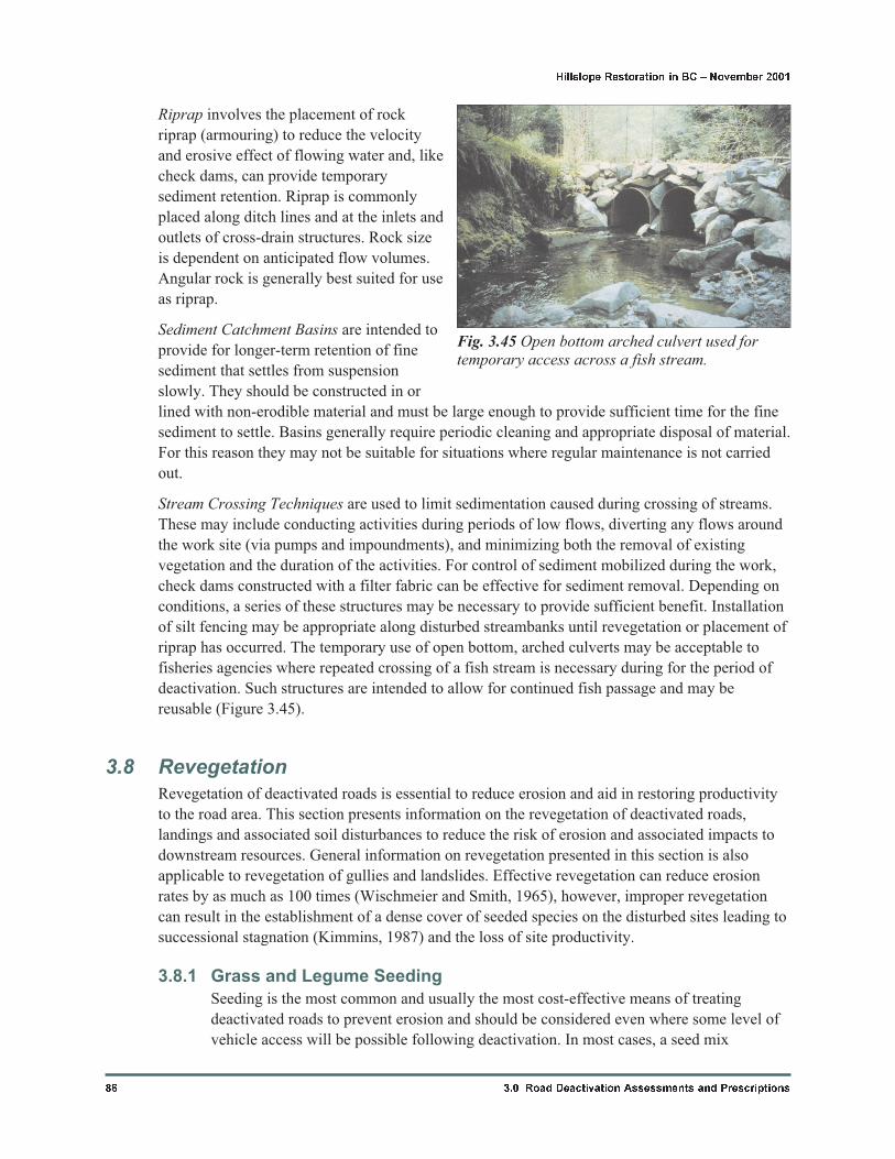
Riprap involves the placement of rock
riprap (armouring) to reduce the velocity
and erosive effect of flowing water and, like
check dams, can provide temporary
sediment retention. Riprap is commonly
placed along ditch lines and at the inlets and
outlets of cross-drain structures. Rock size
is dependent on anticipated flow volumes.
Angular rock is generally best suited for use
as riprap.
Sediment Catchment Basins are intended to
provide for longer-term retention of fine
sediment that settles from suspension
slowly. They should be constructed in or
lined with non-erodible material and must be large enough to provide sufficient time for the fine
sediment to settle. Basins generally require periodic cleaning and appropriate disposal of material.
For this reason they may not be suitable for situations where regular maintenance is not carried
out.
Stream Crossing Techniques are used to limit sedimentation caused during crossing of streams.
These may include conducting activities during periods of low flows, diverting any flows around
the work site (via pumps and impoundments), and minimizing both the removal of existing
vegetation and the duration of the activities. For control of sediment mobilized during the work,
check dams constructed with a filter fabric can be effective for sediment removal. Depending on
conditions, a series of these structures may be necessary to provide sufficient benefit. Installation
of silt fencing may be appropriate along disturbed streambanks until revegetation or placement of
riprap has occurred. The temporary use of open bottom, arched culverts may be acceptable to
fisheries agencies where repeated crossing of a fish stream is necessary during for the period of
deactivation. Such structures are intended to allow for continued fish passage and may be
reusable (Figure 3.45).
3.8 Revegetation
Revegetation of deactivated roads is essential to reduce erosion and aid in restoring productivity
to the road area. This section presents information on the revegetation of deactivated roads,
landings and associated soil disturbances to reduce the risk of erosion and associated impacts to
downstream resources. General information on revegetation presented in this section is also
applicable to revegetation of gullies and landslides. Effective revegetation can reduce erosion
rates by as much as 100 times (Wischmeier and Smith, 1965), however, improper revegetation
can result in the establishment of a dense cover of seeded species on the disturbed sites leading to
successional stagnation (Kimmins, 1987) and the loss of site productivity.
3.8.1 Grass and Legume Seeding
Seeding is the most common and usually the most cost-effective means of treating
deactivated roads to prevent erosion and should be considered even where some level of
vehicle access will be possible following deactivation. In most cases, a seed mix
86 3.0 Road Deactivation Assessments and Prescriptions
Hillslope Restoration in BC � November 2001
Fig. 3.45 Open bottom arched culvert used fortemporary access across a fish stream.
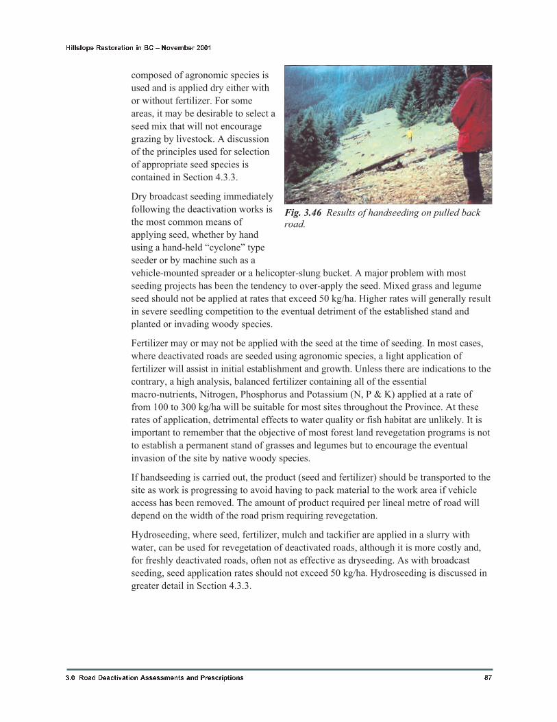
composed of agronomic species is
used and is applied dry either with
or without fertilizer. For some
areas, it may be desirable to select a
seed mix that will not encourage
grazing by livestock. A discussion
of the principles used for selection
of appropriate seed species is
contained in Section 4.3.3.
Dry broadcast seeding immediately
following the deactivation works is
the most common means of
applying seed, whether by hand
using a hand-held “cyclone” type
seeder or by machine such as a
vehicle-mounted spreader or a helicopter-slung bucket. A major problem with most
seeding projects has been the tendency to over-apply the seed. Mixed grass and legume
seed should not be applied at rates that exceed 50 kg/ha. Higher rates will generally result
in severe seedling competition to the eventual detriment of the established stand and
planted or invading woody species.
Fertilizer may or may not be applied with the seed at the time of seeding. In most cases,
where deactivated roads are seeded using agronomic species, a light application of
fertilizer will assist in initial establishment and growth. Unless there are indications to the
contrary, a high analysis, balanced fertilizer containing all of the essential
macro-nutrients, Nitrogen, Phosphorus and Potassium (N, P & K) applied at a rate of
from 100 to 300 kg/ha will be suitable for most sites throughout the Province. At these
rates of application, detrimental effects to water quality or fish habitat are unlikely. It is
important to remember that the objective of most forest land revegetation programs is not
to establish a permanent stand of grasses and legumes but to encourage the eventual
invasion of the site by native woody species.
If handseeding is carried out, the product (seed and fertilizer) should be transported to the
site as work is progressing to avoid having to pack material to the work area if vehicle
access has been removed. The amount of product required per lineal metre of road will
depend on the width of the road prism requiring revegetation.
Hydroseeding, where seed, fertilizer, mulch and tackifier are applied in a slurry with
water, can be used for revegetation of deactivated roads, although it is more costly and,
for freshly deactivated roads, often not as effective as dryseeding. As with broadcast
seeding, seed application rates should not exceed 50 kg/ha. Hydroseeding is discussed in
greater detail in Section 4.3.3.
3.0 Road Deactivation Assessments and Prescriptions 87
Hillslope Restoration in BC � November 2001
Fig. 3.46 Results of handseeding on pulled backroad.
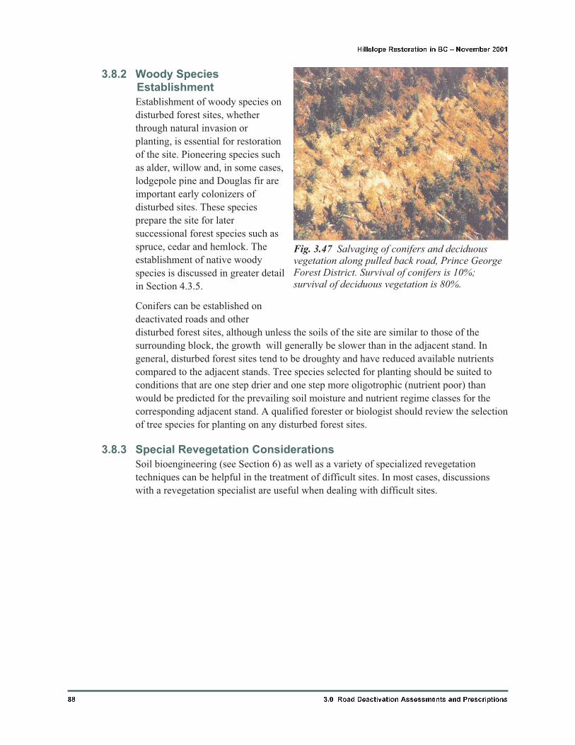
3.8.2 Woody SpeciesEstablishment
Establishment of woody species on
disturbed forest sites, whether
through natural invasion or
planting, is essential for restoration
of the site. Pioneering species such
as alder, willow and, in some cases,
lodgepole pine and Douglas fir are
important early colonizers of
disturbed sites. These species
prepare the site for later
successional forest species such as
spruce, cedar and hemlock. The
establishment of native woody
species is discussed in greater detail
in Section 4.3.5.
Conifers can be established on
deactivated roads and other
disturbed forest sites, although unless the soils of the site are similar to those of the
surrounding block, the growth will generally be slower than in the adjacent stand. In
general, disturbed forest sites tend to be droughty and have reduced available nutrients
compared to the adjacent stands. Tree species selected for planting should be suited to
conditions that are one step drier and one step more oligotrophic (nutrient poor) than
would be predicted for the prevailing soil moisture and nutrient regime classes for the
corresponding adjacent stand. A qualified forester or biologist should review the selection
of tree species for planting on any disturbed forest sites.
3.8.3 Special Revegetation Considerations
Soil bioengineering (see Section 6) as well as a variety of specialized revegetation
techniques can be helpful in the treatment of difficult sites. In most cases, discussions
with a revegetation specialist are useful when dealing with difficult sites.
88 3.0 Road Deactivation Assessments and Prescriptions
Hillslope Restoration in BC � November 2001
Fig. 3.47 Salvaging of conifers and deciduousvegetation along pulled back road, Prince GeorgeForest District. Survival of conifers is 10%;survival of deciduous vegetation is 80%.


