

SAE Mini Baja
Final Presentation
Benjamin Bastidos, Jeramie Goodwin, Eric Lockwood
Anthony McClinton, Caizhi Ming, Ruoheng Pan
May 2, 2014
Overview
• Project Introduction
• Need Statement
• Frame Design and Analysis
• Drivetrain Design and Analysis
• Suspension Design and Analysis
• Cost Report
• Competition Results
• Conclusion
2
Anthony McClinton
Project Introduction
• 2014 SAE Baja Competition
• Customer is SAE International
• Create international design standards
• Hold various collegiate design competitions
• Stakeholder is NAU SAE
• Project advisor is Dr. John Tester
3
Anthony McClinton

Need Statement
• NAU has not won an event at the SAE Baja competition in many years.
• Goal of the frame team is to design the lightest possible frame within the SAE Baja rules.
• Goal changes to overall vehicle safety compliance after completion of the frame.
• Build a drive-train for the Baja vehicle so that it can compete against other teams in all events
• Build a suspension system that is strong and adjustable and a steering system that has agile maneuverability.
4
Anthony McClinton

Frame Design Objectives
• Minimize frame weight
• Minimize cost
• Maximize safety
• Maximize manufacturability
5
Eric Lockwood
Frame Constraints
• AISI 1018 tubing or equivalent strength
• Frame length less than 108 inches
• Frame width less than 40 inches
• Frame height less than 41 inches above seat bottom
• Frame geometry must conform to all SAE Baja Rules
6
Eric Lockwood

Tubing Selection
• SAE specifies AISI 1018 Steel
• 1” Outside Diameter
• 0.120” Wall Thickness
• Other Sizes Allowed
• Equivalent Bending Strength
• Equivalent Bending Stiffness
• 0.062” Minimum Wall Thickness
7
Eric Lockwood
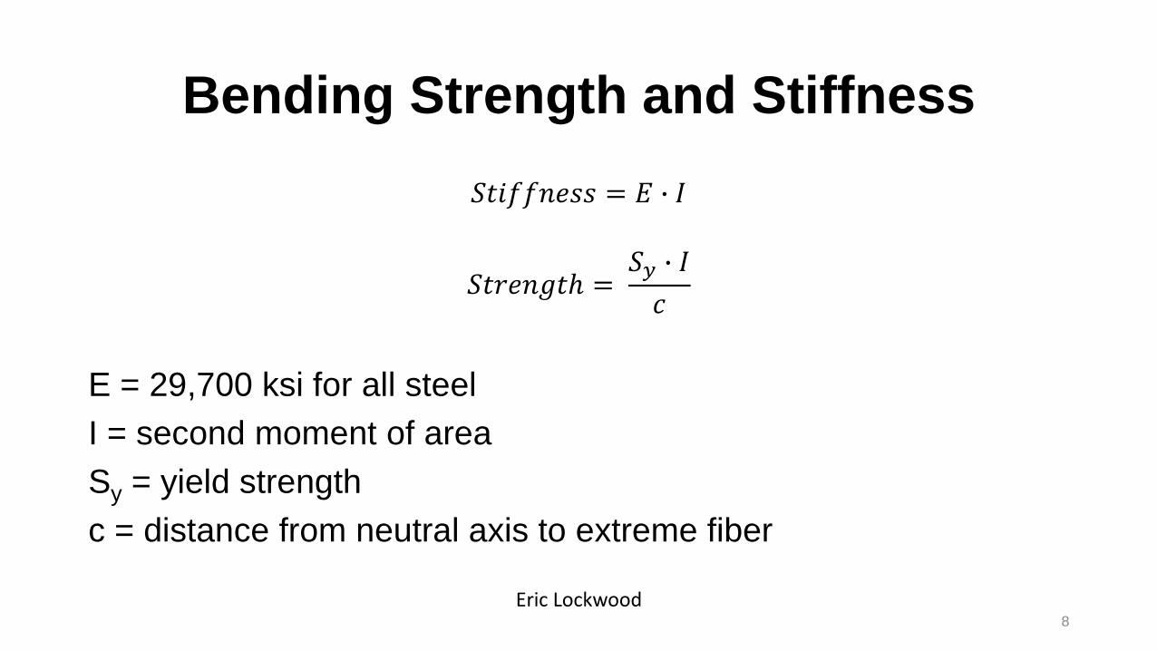
Bending Strength and Stiffness
𝑆𝑡𝑖𝑓𝑓𝑛𝑒𝑠𝑠 = 𝐸 ∙ 𝐼
𝑆𝑡𝑟𝑒𝑛𝑔𝑡ℎ =𝑆𝑦 ∙ 𝐼
𝑐
E = 29,700 ksi for all steel
I = second moment of area
Sy = yield strength
c = distance from neutral axis to extreme fiber
8
Eric Lockwood

AISI 1018
AISI 4130
Diameter [in] Wall Thickness [in] Stiffness [in-lb] Strength [in2-lb]
1.000 0.120 971.5 3.513
Diameter [in] Wall Thickness [in] Stiffness [%] Strength [%] Weight [%]
1.000 0.120 100 118 100
1.125 0.083 113 119 81.9
1.125 0.095 126 131 92.7
1.250 0.065 130 122 72.9
1.375 0.065 176 150 80.6
1.500 0.065 231 181 88.3
9
Eric Lockwood

Final Selection
10
Eric Lockwood

Analysis Assumptions
• Frame Weight: 100 lb
• Drivetrain Weight: 120 lb
• Suspension Weight: 50 lb per corner
• Driver Weight: 250 lb
• AISI 4130 Tubing, 1.25 in Diameter, 0.065 Thickness
11
Eric Lockwood

Drop Test Safety Factor
12
Eric Lockwood

Front Collision Safety Factor
13
Eric Lockwood

Rear Collision Safety Factor
14
Eric Lockwood
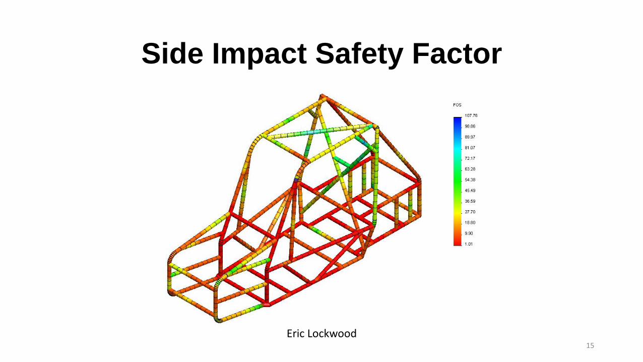
Side Impact Safety Factor
15
Eric Lockwood

Impact Results Summary
Test Max Deflection
[in]
Yield Safety
Factor
Drop 0.089 5.32
Front Collision 0.135 2.90
Rear Collision 0.263 1.45
Side Impact 0.363 1.01
16
Eric Lockwood
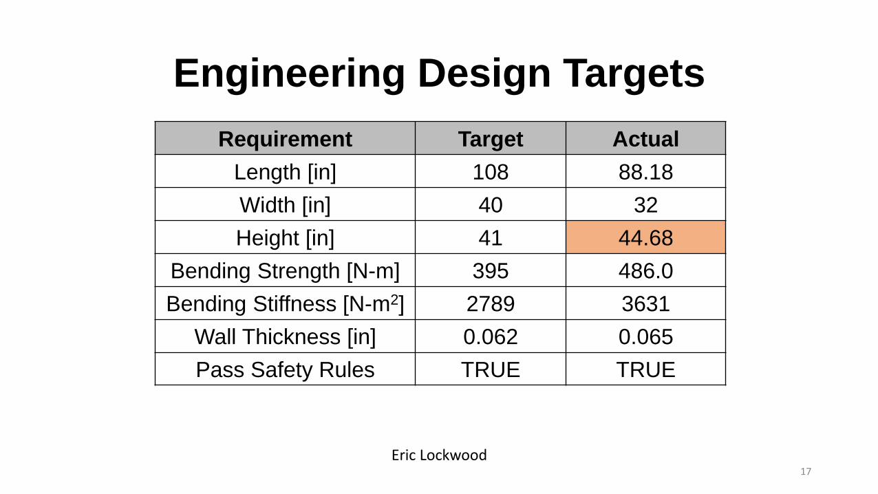
Engineering Design Targets
Requirement Target Actual
Length [in] 108 88.18
Width [in] 40 32
Height [in] 41 44.68
Bending Strength [N-m] 395 486.0
Bending Stiffness [N-m2] 2789 3631
Wall Thickness [in] 0.062 0.065
Pass Safety Rules TRUE TRUE
17
Eric Lockwood

Brake Design
• Dual master cylinders
• Dual brake pedals
• Front and Rear braking
18
Eric Lockwood
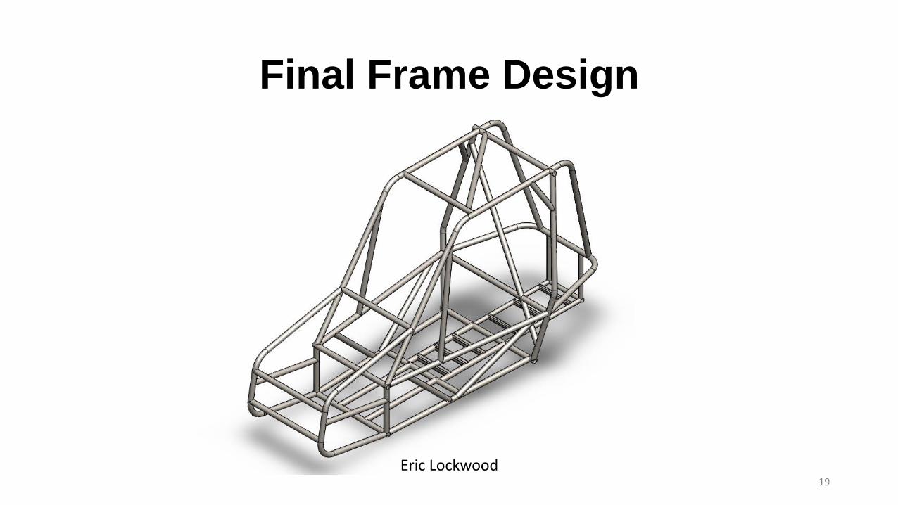
Final Frame Design
19
Eric Lockwood

Final Frame Built
20
Eric Lockwood
Drivetrain Objectives
• To build a drivetrain that will maximize speed and torque of the vehicle.
• To build a drivetrain that is reliable and durable.
• To build a drivetrain that is easy to operate
21
Ruoheng Pan
Drivetrain Analysis
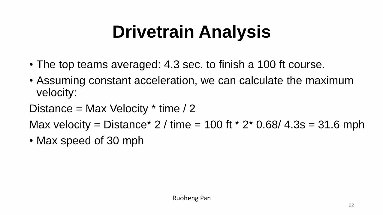
• The top teams averaged: 4.3 sec. to finish a 100 ft course.
• Assuming constant acceleration, we can calculate the maximum velocity:
Distance = Max Velocity * time / 2
Max velocity = Distance* 2 / time = 100 ft * 2* 0.68/ 4.3s = 31.6 mph
• Max speed of 30 mph
22
Ruoheng Pan
Drivetrain Analysis
23
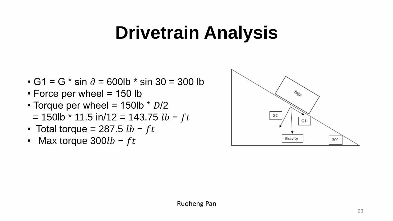
• G1 = G * sin 𝜕 = 600lb * sin 30 = 300 lb
• Force per wheel = 150 lb
• Torque per wheel = 150lb * 𝐷/2
= 150lb * 11.5 in/12 = 143.75 𝑙𝑏 − 𝑓𝑡• Total torque = 287.5 𝑙𝑏 − 𝑓𝑡• Max torque 300𝑙𝑏 − 𝑓𝑡
Ruoheng Pan
Speed and torque Analysis
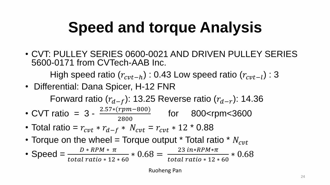
• CVT: PULLEY SERIES 0600-0021 AND DRIVEN PULLEY SERIES 5600-0171 from CVTech-AAB Inc.
High speed ratio (𝑟𝑐𝑣𝑡−ℎ) : 0.43 Low speed ratio (𝑟𝑐𝑣𝑡−𝑙) : 3
• Differential: Dana Spicer, H-12 FNR
Forward ratio (𝑟𝑑−𝑓): 13.25 Reverse ratio (𝑟𝑑−𝑟): 14.36
• CVT ratio = 3 -2.57∗(𝑟𝑝𝑚−800)
2800for 800<rpm<3600
• Total ratio = 𝑟𝑐𝑣𝑡 ∗ 𝑟𝑑−𝑓 ∗ 𝑁𝑐𝑣𝑡 = 𝑟𝑐𝑣𝑡 ∗ 12 * 0.88
• Torque on the wheel = Torque output * Total ratio * 𝑁𝑐𝑣𝑡
• Speed = 𝐷 ∗ 𝑅𝑃𝑀 ∗ 𝜋
𝑡𝑜𝑡𝑎𝑙 𝑟𝑎𝑡𝑖𝑜 ∗ 12 ∗ 60∗ 0.68 =
23 𝑖𝑛∗𝑅𝑃𝑀∗𝜋
𝑡𝑜𝑡𝑎𝑙 𝑟𝑎𝑡𝑖𝑜 ∗ 12 ∗ 60∗ 0.68
24
Ruoheng Pan
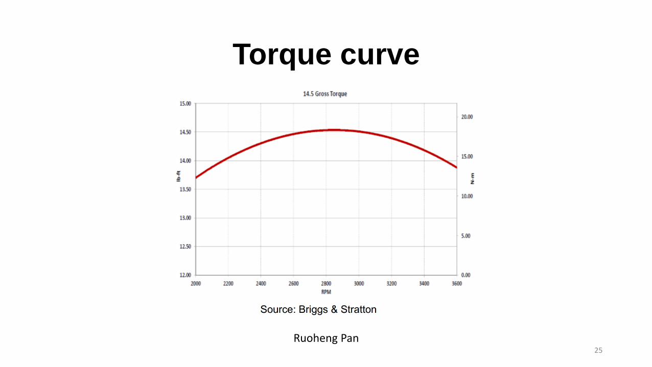
Torque curve
25
Ruoheng Pan

Speed and Torque Calculation
26
Ruoheng Pan

Drivetrain System
Drivetrain system CAD Assembled Drivetrain system
27Caizhi Ming

Engine and Transmission Mount• The team designed a mount for engine and transmission.
• The mount is made by aluminum.
• The team came up with the FEA analysis for this mount.
Assume the load applied on the engine support is 200lb.
Assume the load on the differential support is 80 lb.
Safety factor: The minimum safety factor is 10.97.
Displacement: the maximum displacement on the mount is 0.228mm.
Differential with Mount
Safety Factor Analysis Displacement Analysis 28Caizhi Ming

Drip Pan
Drip Pan CAD Drip Pan
29Caizhi Ming
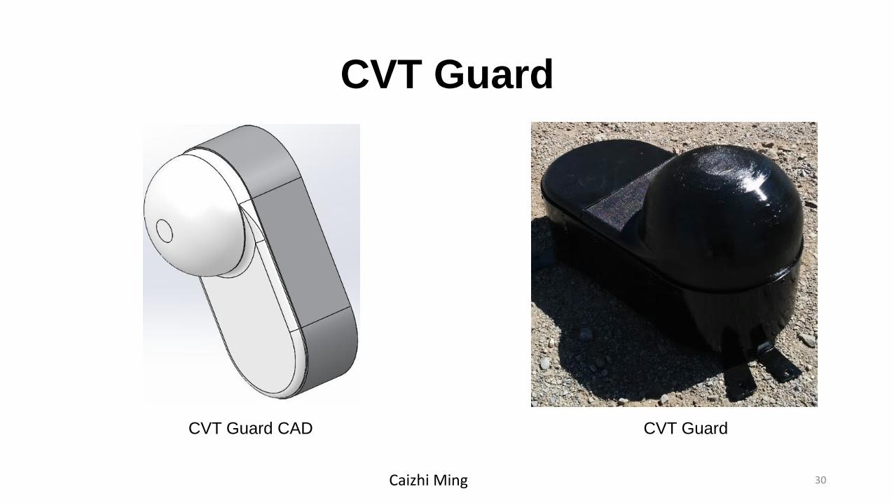
CVT Guard
CVT Guard CAD CVT Guard
30Caizhi Ming

Shifting System
Shifting System CAD Assembled Shifting System31Caizhi Ming
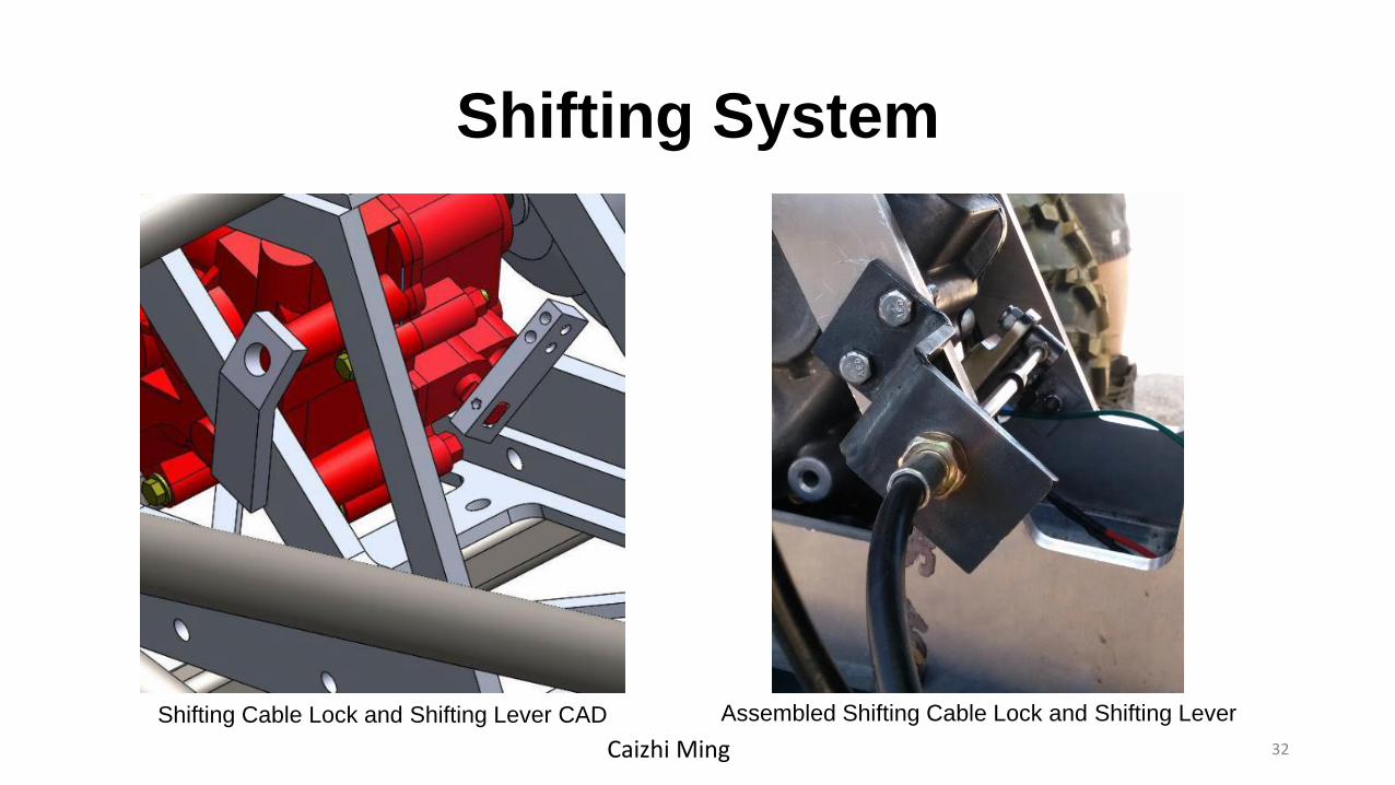
Shifting System
Shifting Cable Lock and Shifting Lever CAD Assembled Shifting Cable Lock and Shifting Lever
32Caizhi Ming
Suspension and Steering Design Objectives
• Strong suspension members
• Suspension systems that will reduce shock and fatigue to components and drivers
• Smaller turning radius than NAU’s previous mini Baja vehicles
Benjamin Bastidos33
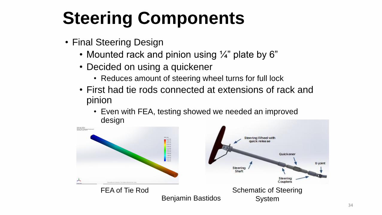
Steering Components
• Final Steering Design
• Mounted rack and pinion using ¼” plate by 6”
• Decided on using a quickener• Reduces amount of steering wheel turns for full lock
• First had tie rods connected at extensions of rack and pinion
• Even with FEA, testing showed we needed an improved design
Schematic of Steering
System
FEA of Tie RodBenjamin Bastidos
34
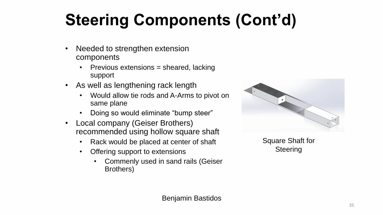
Steering Components (Cont’d)
• Needed to strengthen extension components
• Previous extensions = sheared, lacking support
• As well as lengthening rack length
• Would allow tie rods and A-Arms to pivot on same plane
• Doing so would eliminate “bump steer”
• Local company (Geiser Brothers) recommended using hollow square shaft
• Rack would be placed at center of shaft
• Offering support to extensions
• Commenly used in sand rails (GeiserBrothers)
Square Shaft for
Steering
Benjamin Bastidos35

Front Suspension• Final A-Arm Design
• 20 degree Attachment to hub
• To add simplicity, a bolt through bushing design is used to mount A-Arms to frame
• Shocks previously mounted on lower A-Arm, now on upper
• Allows clearance for steering components
Upper A-Arm Lower A-ArmBenjamin Bastidos
36

Front Suspension (Cont’d)
• Finalized A-Arm length
• Top A-Arm: 11”
• Bottom A-Arm: 12”
• McMaster Carr 5/8” heim joints threaded into A-Arms
• Used for an adjustable camber
• Important for Endurance race
Previous A-Arms
Benjamin Bastidos37

Rear Suspension
• 3-link trailing arm design • Simple geometry
• Less material
• Long travel capabilities
• Length: 17”
• 4130 chromolly steel• 1.25” OD
• 0.095 wall thickness
Jeramie Goodwin38

Rear Suspension Construction Photos
Jeramie Goodwin39
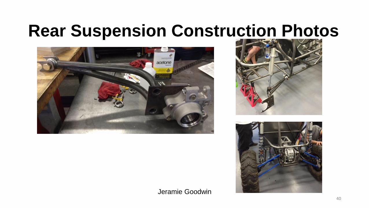
Rear Suspension Construction Photos
Jeramie Goodwin40
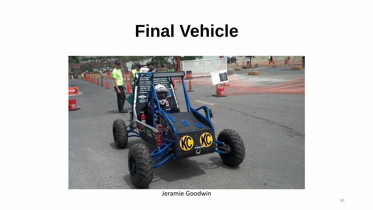
Final Vehicle
41
Jeramie Goodwin

Cost Report
42
Jeramie Goodwin
Competition Results
• Acceleration
• Hill Climb
• Maneuverability
• Suspension and Traction
• Endurance
43
Anthony McClinton
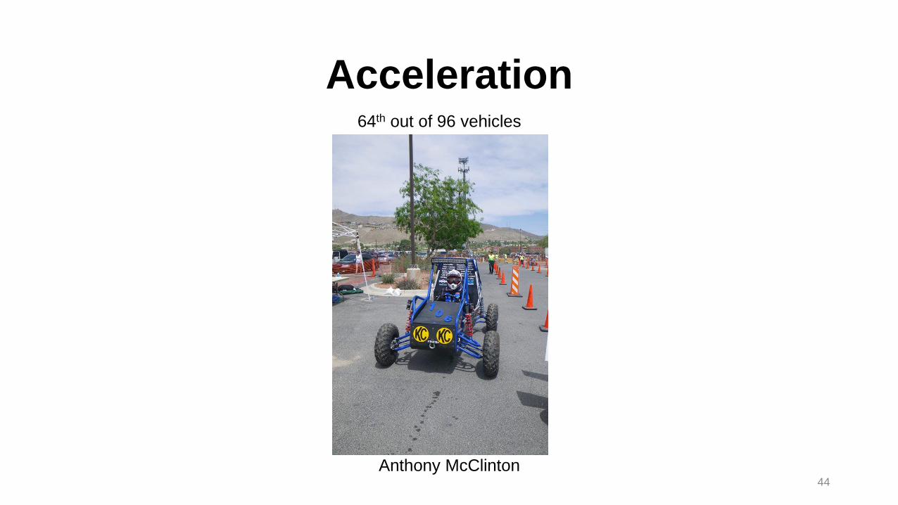
Acceleration
44
64th out of 96 vehicles
Anthony McClinton
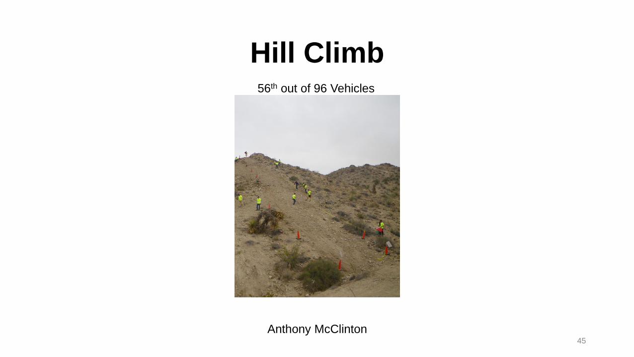
Hill Climb
45
56th out of 96 Vehicles
Anthony McClinton
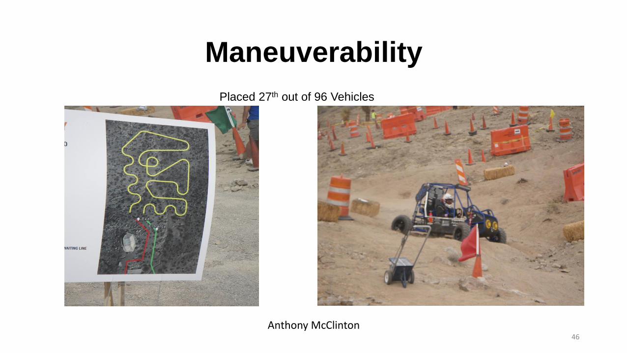
Maneuverability
Placed 27th out of 96 Vehicles
46
Anthony McClinton

Suspension and Traction
Placed 56th out of 96 Vehicles
47
Anthony McClinton

Endurance
Placed 46th out of 96 Vehicles
48
Anthony McClinton
Overall Testing Results
• Placed 51st overall out of 96 vehicles
• Engine mount failed
• A rim cracked
• A flat tire
• Shifter cable became loose
49
Anthony McClinton
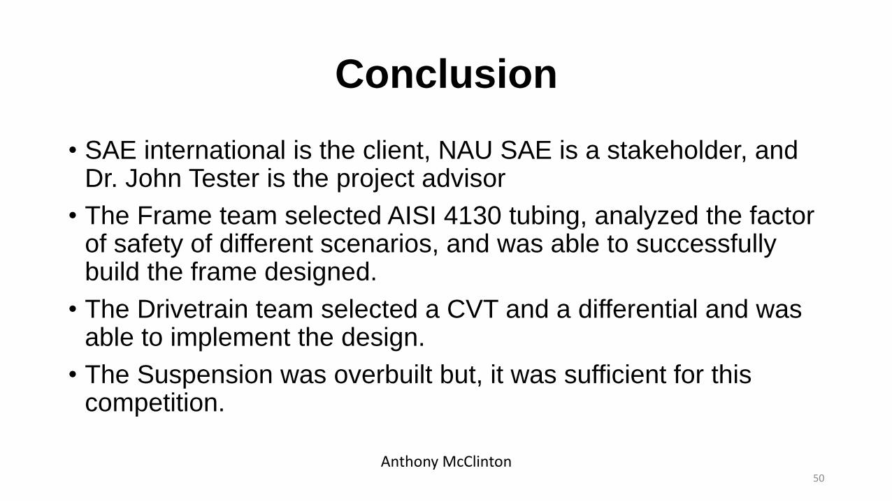
Conclusion
• SAE international is the client, NAU SAE is a stakeholder, and Dr. John Tester is the project advisor
• The Frame team selected AISI 4130 tubing, analyzed the factor of safety of different scenarios, and was able to successfully build the frame designed.
• The Drivetrain team selected a CVT and a differential and was able to implement the design.
• The Suspension was overbuilt but, it was sufficient for this competition.
50
Anthony McClinton
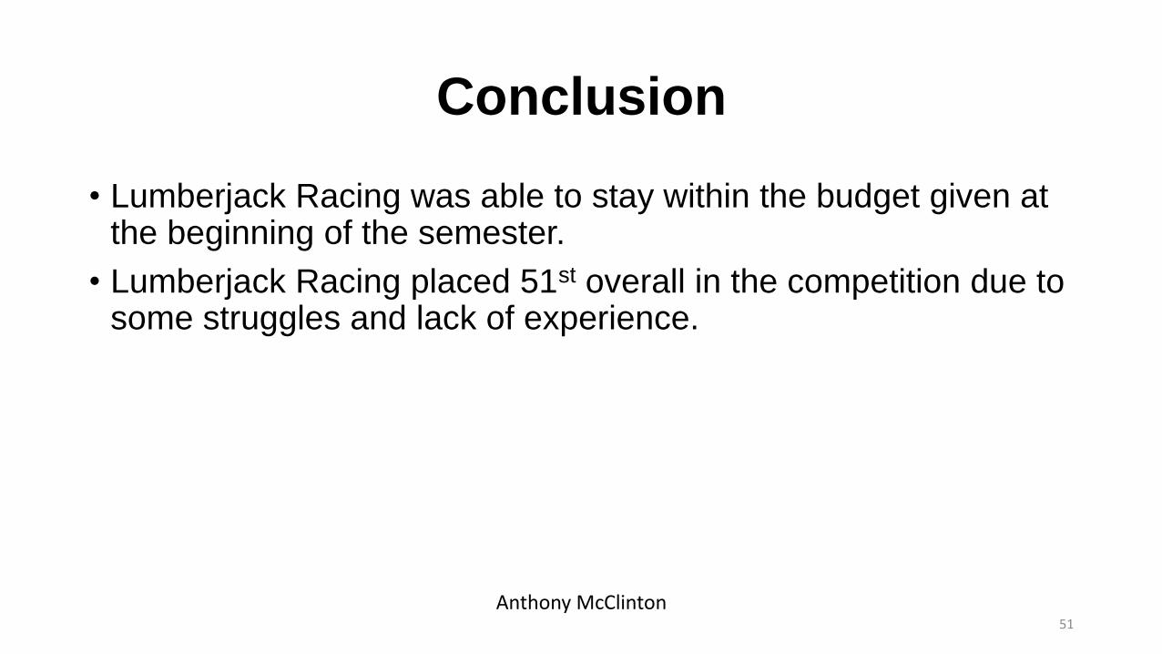
Conclusion
• Lumberjack Racing was able to stay within the budget given at the beginning of the semester.
• Lumberjack Racing placed 51st overall in the competition due to some struggles and lack of experience.
51
Anthony McClinton

References
• Owens, T., Anthony, Jarmulowicz, D., Marc, Jones, Peter “Structural Considerations of a Baja SAE Frame,” SAE Technical Paper 2006-01-3626, 2006.
• Silva, Martins, Maira, Oliveira, R. P. Leopoldo, Neto, C. Alvaro, Varoto, S. Paulo, “An Experimental Investigation on the Modal Characteristics of an Off-Road Competition,” SAE Technical Paper 2003-01-3689, 2003.
• Kluger, M and Long, D. “An Overview of Current Automatic, Manual and Continuously Variable Transmission Efficiencies and Their Projected Future Improvements”. SAE Technical Paper 1999-01-1259.
• Tester, John, Northern Arizona University, personal communication, Nov. 2013.
52
Anthony McClinton

Thanks to our Sponsors!
ASNAUAssociated Students of
Northern Arizona
University
ACEFNSAmbassadors for the
College of Engineering,
Forestry, and Natural
Sciences
Page SteelBill G. Bennett 53
Questions?
54


