
Applied Systems
Technical DataAir cooled chiller, standard efficiency, standard sound
EEDEN13-409
EWAD-E-SS

• Hydronic Systems • Single Unit 1
• Single Unit • Air cooled chiller, standard efficiency, standard sound • EWAD-E-SS
TABLE OF CONTENTSEWAD-E-SS
1 Features . . . . . . . . . . . . . . . . . . . . . . . . . . . . . . . . . . . . . . . . . . . . . . . . . . . . . . . . . . . . . 2
2 Specifications . . . . . . . . . . . . . . . . . . . . . . . . . . . . . . . . . . . . . . . . . . . . . . . . . . . . . . . 3
Technical Specifications . . . . . . . . . . . . . . . . . . . . . . . . . . . . . . . . . . . . . . . . . . . . . 3
Electrical Specifications . . . . . . . . . . . . . . . . . . . . . . . . . . . . . . . . . . . . . . . . . . . . . . 4
3 Features and advantages . . . . . . . . . . . . . . . . . . . . . . . . . . . . . . . . . . . . . . . . . 5
Features and Advantages . . . . . . . . . . . . . . . . . . . . . . . . . . . . . . . . . . . . . . . . . . . . 5
4 General Characteristics. . . . . . . . . . . . . . . . . . . . . . . . . . . . . . . . . . . . . . . . . . . . 7
General characteristics . . . . . . . . . . . . . . . . . . . . . . . . . . . . . . . . . . . . . . . . . . . . . . . 7
5 Nomenclature . . . . . . . . . . . . . . . . . . . . . . . . . . . . . . . . . . . . . . . . . . . . . . . . . . . . . . 12
Nomenclature . . . . . . . . . . . . . . . . . . . . . . . . . . . . . . . . . . . . . . . . . . . . . . . . . . . . . . . 12
6 Options . . . . . . . . . . . . . . . . . . . . . . . . . . . . . . . . . . . . . . . . . . . . . . . . . . . . . . . . . . . . . 13
Options . . . . . . . . . . . . . . . . . . . . . . . . . . . . . . . . . . . . . . . . . . . . . . . . . . . . . . . . . . . . . . 13
7 Capacity tables . . . . . . . . . . . . . . . . . . . . . . . . . . . . . . . . . . . . . . . . . . . . . . . . . . . . 20
Cooling Capacity Tables . . . . . . . . . . . . . . . . . . . . . . . . . . . . . . . . . . . . . . . . . . . . 20
8 Dimensional drawings . . . . . . . . . . . . . . . . . . . . . . . . . . . . . . . . . . . . . . . . . . . . 22
Dimensional Drawings . . . . . . . . . . . . . . . . . . . . . . . . . . . . . . . . . . . . . . . . . . . . . . 22
9 Sound data . . . . . . . . . . . . . . . . . . . . . . . . . . . . . . . . . . . . . . . . . . . . . . . . . . . . . . . . . 24
Sound Level Data . . . . . . . . . . . . . . . . . . . . . . . . . . . . . . . . . . . . . . . . . . . . . . . . . . . 24
10 Installation . . . . . . . . . . . . . . . . . . . . . . . . . . . . . . . . . . . . . . . . . . . . . . . . . . . . . . . . . . 26
Installation Method . . . . . . . . . . . . . . . . . . . . . . . . . . . . . . . . . . . . . . . . . . . . . . . . . . 26
11 Operation range . . . . . . . . . . . . . . . . . . . . . . . . . . . . . . . . . . . . . . . . . . . . . . . . . . . 30
Operation Range . . . . . . . . . . . . . . . . . . . . . . . . . . . . . . . . . . . . . . . . . . . . . . . . . . . . 30
12 Hydraulic performance. . . . . . . . . . . . . . . . . . . . . . . . . . . . . . . . . . . . . . . . . . . . 34
Water Pressure Drop Curve Evaporator . . . . . . . . . . . . . . . . . . . . . . . . . . . . 34
13 Specification text . . . . . . . . . . . . . . . . . . . . . . . . . . . . . . . . . . . . . . . . . . . . . . . . . . 35
Specification Text . . . . . . . . . . . . . . . . . . . . . . . . . . . . . . . . . . . . . . . . . . . . . . . . . . . 35
• Single Unit • Air cooled chiller, standard efficiency, standard sound • EWAD-E-SS
11
• Hydronic Systems • Single Unit2
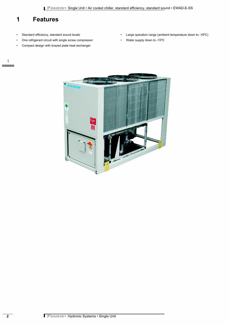
1 Features
Single Unit Hydronic Sys EWAD-E-SS Air cooled • Standard efficiency, standard sound levels
• One refrigerant circuit with single screw compressor
• Compact design with brazed plate heat exchanger
• Large operation range (ambient temperature down to -18ºC)
• Water supply down to -15ºC
3
12
• Hydronic Systems • Single Unit 3
• Single Unit • Air cooled chiller, standard efficiency, standard sound • EWAD-E-SS
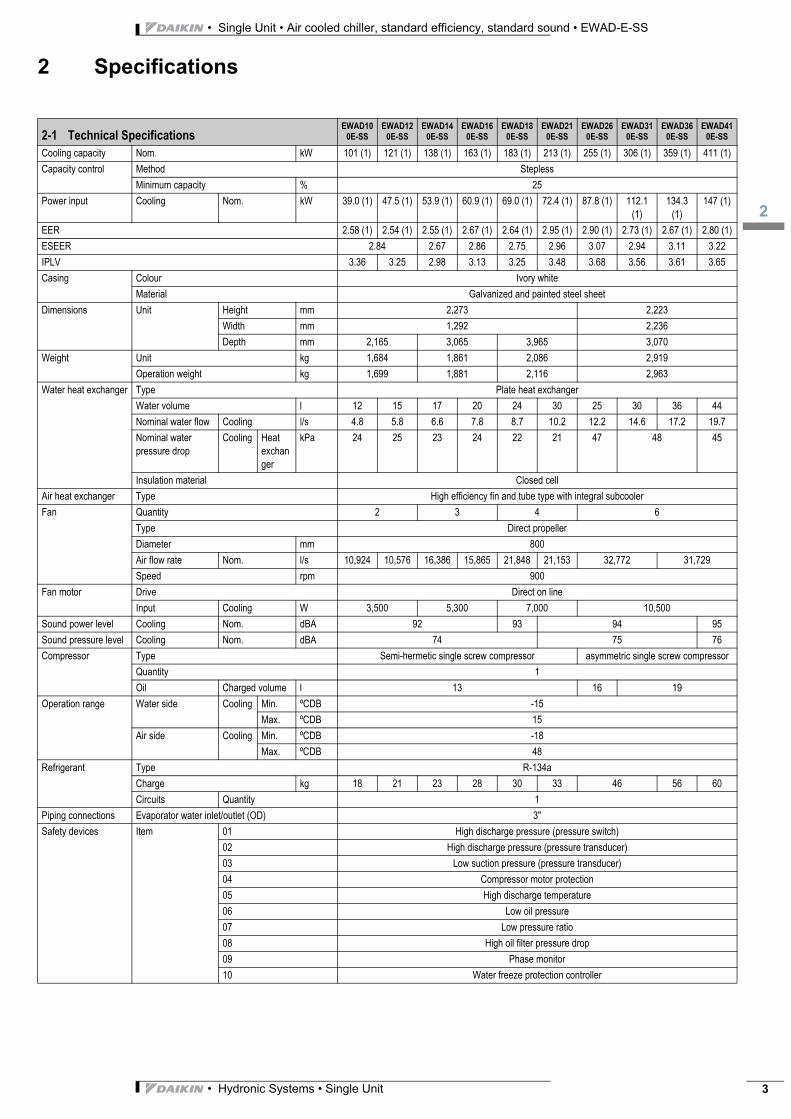
2 Specifications
2-1 Technical SpecificationsEWAD10
0E-SSEWAD12
0E-SSEWAD14
0E-SSEWAD16
0E-SSEWAD18
0E-SSEWAD21
0E-SSEWAD26
0E-SSEWAD31
0E-SSEWAD36
0E-SSEWAD41
0E-SS
Cooling capacity Nom. kW 101 (1) 121 (1) 138 (1) 163 (1) 183 (1) 213 (1) 255 (1) 306 (1) 359 (1) 411 (1)
Capacity control Method Stepless
Minimum capacity % 25
Power input Cooling Nom. kW 39.0 (1) 47.5 (1) 53.9 (1) 60.9 (1) 69.0 (1) 72.4 (1) 87.8 (1) 112.1 (1)
134.3 (1)
147 (1)
EER 2.58 (1) 2.54 (1) 2.55 (1) 2.67 (1) 2.64 (1) 2.95 (1) 2.90 (1) 2.73 (1) 2.67 (1) 2.80 (1)
ESEER 2.84 2.67 2.86 2.75 2.96 3.07 2.94 3.11 3.22
IPLV 3.36 3.25 2.98 3.13 3.25 3.48 3.68 3.56 3.61 3.65
Casing Colour Ivory white
Material Galvanized and painted steel sheet
Dimensions Unit Height mm 2,273 2,223
Width mm 1,292 2,236
Depth mm 2,165 3,065 3,965 3,070
Weight Unit kg 1,684 1,861 2,086 2,919
Operation weight kg 1,699 1,881 2,116 2,963
Water heat exchanger Type Plate heat exchanger
Water volume l 12 15 17 20 24 30 25 30 36 44
Nominal water flow Cooling l/s 4.8 5.8 6.6 7.8 8.7 10.2 12.2 14.6 17.2 19.7
Nominal water pressure drop
Cooling Heat exchanger
kPa 24 25 23 24 22 21 47 48 45
Insulation material Closed cell
Air heat exchanger Type High efficiency fin and tube type with integral subcooler
Fan Quantity 2 3 4 6
Type Direct propeller
Diameter mm 800
Air flow rate Nom. l/s 10,924 10,576 16,386 15,865 21,848 21,153 32,772 31,729
Speed rpm 900
Fan motor Drive Direct on line
Input Cooling W 3,500 5,300 7,000 10,500
Sound power level Cooling Nom. dBA 92 93 94 95
Sound pressure level Cooling Nom. dBA 74 75 76
Compressor Type Semi-hermetic single screw compressor asymmetric single screw compressor
Quantity 1
Oil Charged volume l 13 16 19
Operation range Water side Cooling Min. ºCDB -15
Max. ºCDB 15
Air side Cooling Min. ºCDB -18
Max. ºCDB 48
Refrigerant Type R-134a
Charge kg 18 21 23 28 30 33 46 56 60
Circuits Quantity 1
Piping connections Evaporator water inlet/outlet (OD) 3"
Safety devices Item 01 High discharge pressure (pressure switch)
02 High discharge pressure (pressure transducer)
03 Low suction pressure (pressure transducer)
04 Compressor motor protection
05 High discharge temperature
06 Low oil pressure
07 Low pressure ratio
08 High oil filter pressure drop
09 Phase monitor
10 Water freeze protection controller
• Single Unit • Air cooled chiller, standard efficiency, standard sound • EWAD-E-SS
12
• Hydronic Systems • Single Unit4
2 Specifications
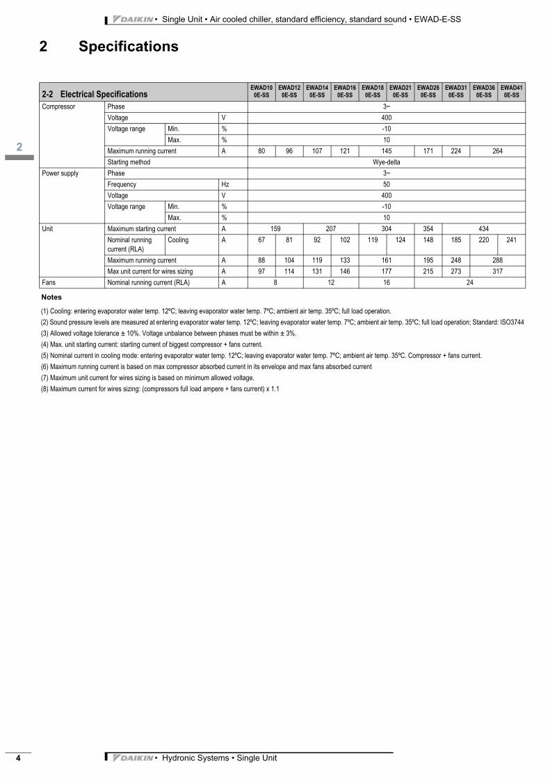
Notes
(1) Cooling: entering evaporator water temp. 12ºC; leaving evaporator water temp. 7ºC; ambient air temp. 35ºC; full load operation.
(2) Sound pressure levels are measured at entering evaporator water temp. 12ºC; leaving evaporator water temp. 7ºC; ambient air temp. 35ºC; full load operation; Standard: ISO3744
(3) Allowed voltage tolerance ± 10%. Voltage unbalance between phases must be within ± 3%.
(4) Max. unit starting current: starting current of biggest compressor + fans current.
(5) Nominal current in cooling mode: entering evaporator water temp. 12ºC; leaving evaporator water temp. 7ºC; ambient air temp. 35ºC. Compressor + fans current.
(6) Maximum running current is based on max compressor absorbed current in its envelope and max fans absorbed current
(7) Maximum unit current for wires sizing is based on minimum allowed voltage.
(8) Maximum current for wires sizing: (compressors full load ampere + fans current) x 1.1
2-2 Electrical SpecificationsEWAD10
0E-SSEWAD12
0E-SSEWAD14
0E-SSEWAD16
0E-SSEWAD18
0E-SSEWAD21
0E-SSEWAD26
0E-SSEWAD31
0E-SSEWAD36
0E-SSEWAD41
0E-SS
Compressor Phase 3~
Voltage V 400
Voltage range Min. % -10
Max. % 10
Maximum running current A 80 96 107 121 145 171 224 264
Starting method Wye-delta
Power supply Phase 3~
Frequency Hz 50
Voltage V 400
Voltage range Min. % -10
Max. % 10
Unit Maximum starting current A 159 207 304 354 434
Nominal running current (RLA)
Cooling A 67 81 92 102 119 124 148 185 220 241
Maximum running current A 88 104 119 133 161 195 248 288
Max unit current for wires sizing A 97 114 131 146 177 215 273 317
Fans Nominal running current (RLA) A 8 12 16 24
3
13
• Hydronic Systems • Single Unit 5
• Single Unit • Air cooled chiller, standard efficiency, standard sound • EWAD-E-SS
3 Features and advantages
3 - 1 Features and Advantages
Features and advantages
Low operating cost
EWAD~E- is the result of careful design, aimed to optimizing the energy effi ciency of the chillers, with the objective of bringing
down operating costs and improving installation profi tability, effectiveness and economical management.
The EWAD~E- chillers use the new very high effi ciency single rotor screw compressor design, large condenser coil surface
area for maximum heat transfer and low discharge pressure, advanced technology condenser fans, a plate to plate direct-
expansion evaporator with low refrigerant pressure drops.
Low operating sound levels
Very low noise levels both at full load and part load conditions are achieved by the latest compressor design and by a unique
new fan that moves large volume of air at exceptionally low sound levels and by the virtually vibration-free operation.
Excellent Serviceability
Field serviceability has not been sacrifi ced to meet design performance objectives. The compressor is equipped with discharge,
liquid and suction shut off valves. The compressor and serviceable components such as fi lter-driers are located on the outside
edges of the base allowing ready access. The shaped of the coil allows an easy access for inspection and service. The
MicroTech III controller gives detailed information on the causes of an alarm or fault.
Proven Reliability
Full factory testing of every unit with water hook-up helps provide a trouble-free start-up. Extensive quality control checks
during testing means that each equipment protection and operating control is properly adjusted and operates correctly before
it leaves the factory.
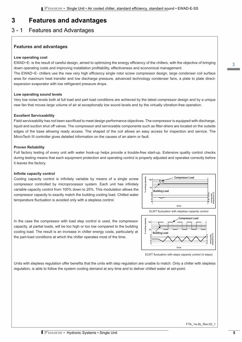
Infi nite capacity control
Cooling capacity control is infi nitely variable by means of a single screw
compressor controlled by microprocessor system. Each unit has infi nitely
variable capacity control from 100% down to 25%. This modulation allows the
compressor capacity to exactly match the building cooling load. Chilled water
temperature fl uctuation is avoided only with a stepless control.
In the case the compressor with load step control is used, the compressor
capacity, at partial loads, will be too high or too low compared to the building
cooling load. The result is an increase in chiller energy costs, particularly at
the part-load conditions at which the chiller operates most of the time.
Units with stepless regulation offer benefi ts that the units with step regulation are unable to match. Only a chiller with stepless
regulation, is able to follow the system cooling demand at any time and to deliver chilled water at set-point.
FTA_1a-2b_Rev.02_1
time
ELWT fl uctuation with stepless capacity control
ELWT fl uctuation with steps capacity control (4 steps)
Compressor Load
Building Load
lea
vin
g w
ate
r
tem
pe
ratu
re [°C
]% c
oo
lin
g c
ap
acit
y
Compressor Load
time
lea
vin
g w
ate
r
tem
pe
ratu
re [°C
]% c
oo
lin
g c
ap
acit
y
Building Load
time
• Single Unit • Air cooled chiller, standard efficiency, standard sound • EWAD-E-SS
13
• Hydronic Systems • Single Unit6
3 Features and advantages
3 - 1 Features and Advantages
FTA_1a-2b_Rev.02_2
Superior control logic
The new MicroTech III controller provides an easy to use control environmental. The control logic is designed to provide
maximum effi ciency, to continue operation in unusual operating conditions and to provide a history of unit operation. One of
the greatest benefi ts is the easy interface with LonWorks, Bacnet, Ethernet TCP/IP or Modbus communications.
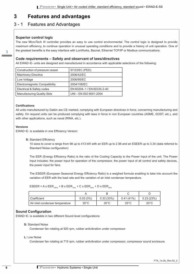
Code requirements – Safety and observant of laws/directives
All EWAD~E- units are designed and manufactured in accordance with applicable selections of the following:
Construction of pressure vessel 97/23/EC (PED)
Machinery Directive 2006/42/EC
Low Voltage 2006/95/EC
Electromagnetic Compatibility 2004/108/EC
Electrical & Safety codes EN 60204–1 / EN 60335-2-40
Manufacturing Quality Stds UNI – EN ISO 9001:2004
Certifi cations
All units manufactured by Daikin are CE marked, complying with European directives in force, concerning manufacturing and
safety. On request units can be produced complying with laws in force in non European countries (ASME, GOST, etc.), and
with other applications, such as naval (RINA, etc.).
Versions
EWAD~E- is available in one Effi ciency Version:
S: Standard Effi ciency
10 sizes to cover a range from 98 up to 413 kW with an EER up to 2.98 and an ESEER up to 3.34 (data referred to
Standard Noise confi guration)
The EER (Energy Effi ciency Ratio) is the ratio of the Cooling Capacity to the Power Input of the unit. The Power
Input includes: the power input for operation of the compressor, the power input of all control and safety devices,
the power input for fans.
The ESEER (European Seasonal Energy Effi ciency Ratio) is a weighed formula enabling to take into account the
variation of EER with the load rate and the variation of air inlet condenser temperature.
ESEER = A x EER100%
+ B x EER75%
+ C x EER50%
+ D x EER25%
A B C D
Coeffi cient 0.03 (3%) 0.33 (33%) 0.41 (41%) 0.23 (23%)
Air inlet condenser temperature 35°C 30°C 25°C 20°C
Sound Confi guration
EWAD~E- is available in two different Sound level confi gurations:
S: Standard Noise
Condenser fan rotating at 920 rpm, rubber antivibration under compressor
L: Low Noise
Condenser fan rotating at 715 rpm, rubber antivibration under compressor, compressor sound enclosure.
3
14
• Hydronic Systems • Single Unit 7
• Single Unit • Air cooled chiller, standard efficiency, standard sound • EWAD-E-SS
4 General Characteristics
4 - 1 General characteristics
GNC_1a-2a-3a-4c-5b-6_Rev.03_1
Cabinet and structure
The cabinet is made of galvanized steel sheet and painted to provide a high resistance to corrosion. Colour Ivory White
(Munsell code 5Y7.5/1) (±RAL7044).The base frame has eye-hook for lifting the unit with ropes for an easy installation. The
weight is uniformly distributed along the profi les of the base and this facilitates the arrangement of the unit.
Screw compressors with integrated oil separator
From size EWAD100E-SS to size EWAD 210E-SS and from size EWAD100E-SL to size EWAD210E-SL
The compressor is semi-hermetic, single-screw type with gate-rotors (made of carbon impregnated engineered composite
material). The compressor has one slide managed by the unit microprocessor for infi nitely modulating the capacity from 100%
to 25%. An integrated high effi ciency oil separator maximises the oil separation. Standard Start is Wye-delta (Y- ) type.
From size EWAD260E-SS to size EWAD 410E-SS and from size EWAD250E-SL to size EWAD400E-SL
The compressor is semi-hermetic, single-screw type with gate-rotor (with the latest high-strength fi bre reinforced star material).
The compressor has an asymmetric slide regulation managed by the unit controller for infi nitely modulating capacity from
100% to 25%. An integrated high effi ciency oil separator maximizes the oil separation. Standard Start is Wye-delta (Y- ) type.
Ecological R-134a refrigerant
The compressors have been designed to operate with R-134a, ecological refrigerant with zero ODP (Ozone Depletion
Potential) and very low GWP (Global Warming Potential) that means low TEWI (Total Equivalent Warming Impact).
Evaporator
The units are equipped with a direct expansion plate to plate type evaporator. This heat exchanger is made of stainless steel
brazed plates and is covered with a 10mm closed cell insulation material. The exchanger is equipped with an heater for
protection against freezing down to –28°C.
Each evaporator has 1circuit (one compressor) and is manufactured in accordance to PED approval. The evaporator water
outlet connections are 3”.
Condenser coils
The condenser is manufactured with internally enhanced seamless copper tubes arranged in a staggered row pattern and
mechanically expanded into lanced and rippled aluminium condenser fi ns with full fi n collars. An integral sub-cooler circuit
provides sub-cooling to effectively eliminate liquid fl ashing and increase cooling capacity without increasing the power input.
Condenser coil fans
The condenser fans are propeller type with high effi ciency design blades to maximize performances. The material of the
blades is glass reinforced resin and each fan is protected by a guard. Fan motors are protected by circuit breakers installed
inside the electrical panel as a standard. The motors are IP54.
Electronic expansion valve
The unit is equipped with the most advanced electronic expansion valves to achieve precise control of refrigerant mass
fl ow. As today’s system requires improved energy effi ciency, tighter temperature control, wider range of operating conditions
and incorporate features like remote monitoring and diagnostics, the application of electronic expansion valves becomes
mandatory. Electronic expansion valves possess features that make it unique: short opening and closing time, high resolution,
positive shut-off function to eliminate use of additional solenoid valve, continuous modulation of mass fl ow without stress in the
refrigerant circuit and corrosion resistance stainless steel body.
Electronic Expansion Valves are typically working with lower P between high and low pressure side, than a thermostatic
expansion valve. The electronic expansion valve allows the system to work with low condenser pressure (winter time) without
any refrigerant fl ow problems and with a perfect chilled water leaving temperature control.
• Single Unit • Air cooled chiller, standard efficiency, standard sound • EWAD-E-SS
14
• Hydronic Systems • Single Unit8
4 General Characteristics
4 - 1 General characteristics
GNC_1a-2a-3a-4c-5b-6_Rev.03_2
Refrigerant Circuit
Each unit has 1 refrigerant circuit and includes:
• Compressor with integrated oil separator
• Air Cooled Condenser
• Electronic expansion valve
• Evaporator
• Discharge line shut off valve
• Liquid line shut off valve
• Suction line shut off valve
• Sight glass with moisture indicator
• Filter drier
• Charging valves
• High pressure switch
• High and low pressure transducers
Electrical control panel
Power and control are located in the main panel that is manufactured to ensure protection against all weather conditions. The
electrical panel is IP54 and (when opening the doors) internally protected with Plexiglas panel against possible accidental
contact with electrical components (IP20). The main panel is fi tted with a main switch interlocked door.
Power Section
The power section includes compressors fuses, fan circuit breaker, fan contactors and control circuit transformer.
MicroTech III controller
MicroTech III controller is installed as standard; it can be used to modify unit set-points and check control parameters. A
built-in display shows chiller operating status plus temperatures and pressures of water, refrigerant and air, programmable
values, set-points. A sophisticated software with predictive logic, selects the most energy effi cient combination of
compressors, EEXV and condenser fans to keep stable operating conditions to maximise chiller energy effi ciency and
reliability.
MicroTech III is able to protect critical components based on external signs from its system (such as motor temperatures,
refrigerant gas and oil pressures, correct phase sequence, pressure switches and evaporator). The input coming from
the high pressure switch cuts all digital output from the controller in less than 50ms, this is an additional security for the
equipment.
Fast program cycle (200ms) for a precise monitoring of the system. Floating point calculations supported for increased
accuracy in P/T conversions.
Control section - main features
• Management of the compressor stepless capacity and fans modulation.
• Chillers enabled to work in partial failure condition.
• Full routine operation at condition of:
- high ambient temperature value
- high thermal load
- high evaporator entering water temperature (start-up)
• Display of evaporator entering/leaving water temperature.
• Display of Outdoor Ambient Temperature.
• Display of condensing-evaporating temperature and pressure, suction and discharge superheat for each circuit.
• Leaving water evaporator temperature regulation. Temperature tolerance = 0,1°C.
• Compressor and evaporator pumps hours counter.
• Display of Status Safety Devices.
• Number of starts and compressor working hours.
3
14
• Hydronic Systems • Single Unit 9
• Single Unit • Air cooled chiller, standard efficiency, standard sound • EWAD-E-SS
4 General Characteristics
4 - 1 General characteristics
GNC_1a-2a-3a-4c-5b-6_Rev.03_3
• Optimized management of compressor load.
• Fan management according to condensing pressure.
• Re-start in case of power failure (automatic / manual).
• Soft Load (optimized management of the compressors load during the start-up).
• Start at high evaporator water temperature.
• Return Reset (Set Point Reset based on return water temperature).
• OAT (Outside Ambient temperature) Reset.
• Set point Reset (optional).
• Application and system upgrade with commercial SD cards.
• Ethernet port for remote or local servicing using standard web browsers.
• Two different sets of default parameters could be stored for easy restore.
Safety device / logic for each refrigerant circuit
• High pressure (pressure switch).
• High pressure (transducer).
• Low pressure (transducer).
• Fans circuit breaker.
• High compressor discharge temperature.
• High motor winding temperature.
• Phase Monitor.
• Low pressure ratio.
• High oil pressure drop.
• Low oil pressure.
• No pressure change at start.
System security
• Phase monitor.
• Low Ambient temperature lock-out.
• Freeze protection.
Regulation type
Proportional + integral + derivative regulation on the leaving water evaporator output probe.
Condensing pressure
Condensing pressure can be controlled in according to the entering air temperature to the condenser coil. The fans
can be managed either with steps, or with a 0/10 V modulating signal or with a mixed 0/10V + Steps strategy
to cover all possible operational conditions.
MicroTech III
MicroTech III built-in terminal has the following features.
• 164x44 dots liquid crystal display with white back lighting. Supports Unicode fonts for multi-lingual.
• Key-pad consisting of 3 keys.
• Push’n’Roll control for an increased usability.
• Memory to protect the data.
• General faults alarm relays.
• Password access to modify the setting.
• Single Unit • Air cooled chiller, standard efficiency, standard sound • EWAD-E-SS
14
• Hydronic Systems • Single Unit10
4 General Characteristics
4 - 1 General characteristics
GNC_1a-2a-3a-4c-5b-6_Rev.03_4
• Application security to prevent application tampering or hardware usability with third party applications.
• Service report displaying all running hours and general conditions.
• Alarm history memory to allow an easy fault analysis.
Supervising systems (on request)
MicroTech III remote control
MicroTech III is able to communicate to BMS (Building Management System) based on the most common protocols as:
• ModbusRTU
• LonWorks, now also based on the international 8040 Standard Chiller Profi le and LonMark Technology
• BacNet BTP certifi ef over IP and MS/TP (class 4) (Native)
• Ethernet TCP/IP.
Standard accessories (supplied on basic unit)
Wye-Delta Compressors starter (Y-D) – For low inrush current and reduced starting torque.
Double set-point – Dual leaving water temperature set-points.
Fans thermal overload relays – Safety devices against fan motor overloading in addition to the normal protection envisaged
by the electrical windings.
Phase monitor – The phase monitor controls that phases sequence is correct and controls phase loss.
10mm evaporator insulation
Evaporator electric heater – Electric heater controlled by a thermostat to protect the evaporator from freezing down to -28°C
ambient temperature, providing the power supply is on.
Electronic expansion valve
Discharge line shut off valves – Installed on the discharge port of the compressor to facilitate maintenance operation.
Suction line shut off valve – Installed on the suction port of the compressor to facilitate maintenance operation.
Outside ambient temperature sensor and reset of leaving water temperature set-point.
Compressor hour run meter.
General fault – Alarm relay.
Set-point reset – The leaving water temperature set-point can be overwritten with the following options: 4-20mA from external
source (by user); outside ambient temperature; evaporator water temperature t.
Demand limit – User can limit the load of the unit by 4-20mA signal or by network system
Alarm from external device – Microprocessor is able to receive an alarm signal from an external device (pump etc…). User
can decide if this alarm signal will stop the unit or not.
Main switch interlock door
Emergency stop
Fans circuit breakers – Safety device against motor overloading and short circuit
Low pressure side manometers
3
14
• Hydronic Systems • Single Unit 11
• Single Unit • Air cooled chiller, standard efficiency, standard sound • EWAD-E-SS
4 General Characteristics
4 - 1 General characteristics
GNC_1a-2a-3a-4c-5b-6_Rev.03_5-6
Options (on request)
Total heat recovery – Provided with plate to plate heat exchangers to produce hot water.
Partial heat recovery – Plate to plate heat exchangers installed between the compressor discharge and the condenser coil,
allowing to produce hot water.
Soft starter – Electronic starting device to reduce the mechanical stress during compressor start-up.
Brine version – Allows the unit to operate down to -8°C leaving liquid temperature (antifreeze required).
Compressor thermal overload relays – Safety devices against compressor motor overloading. This device together with
internal motor protection (standard) guarantee the best safety system for compressor motor.
Under/Over Voltage – This device control the voltage value of power supply and stop the chiller if the value exceeds the
allowed operating limits.
Energy Meter – This device allows to measure the energy absorbed by the chiller during its life. It is installed inside the
control box mounted on a DIN rail and show on a digital display: Line-to-Line Voltage, Phase and Average Current, Active and
Reactive Power, Active Energy, Frequency.
Capacitors for power factor correction – To increase the operating power factor of the unit at nominal operating conditions.
The capacitors are “dry” self-regenerating type with over pressure disconnectiong safety device insulated with a no toxic
dielectric mix with no PCB or PCT.
Current limit – To limit maximum absorbed current of the unit whenever is required
20mm evaporator insulation
Fan speed regulation – To control the fan speed revolution for smooth operating control of the unit. During low ambient
temperature operation, this option improves also the sound level of the unit.
With “Fan speed regulation” option, by different microprocessor setting, it is also possible to set the “Fan Silent Mode”
confi guration. It means that the microprocessor clock switches the fan at low speed according to the client setting (i.e. Night &
Day), providing that the ambient temperature/condensing pressure is allowing the speed change.
It allows a perfect condensing control down to –10°C.
Speedtrol – Continuous fan speed modulation on the fi rst fan of each circuit. It allows the unit working with air temperature
down to –18°C.
Condenser coil guards
Cu-Cu condensing coils – To give better protection against corrosion by aggressive environments.
Cu-Cu-Sn condensing coils – To give better protection against corrosion in aggressive environments and by salty air.
Alucoat condensing coils – Fins are protected by a special acrylic paint with a high resistance to corrosion.
Evaporator Flow switch – Supplied separately to be wired and installed on the evaporator water piping (by the customer).
High pressure side manometer.
Kit container
Rubber type anti vibration mounts – Supplied separately, these are positioned under the base of the unit during installation
to reduce vibrations.
Spring type anti vibration mounts – Supplied separately, these are positioned under the base of the unit during installation.
Ideal for dampening vibrations for installation on roofs and metallic structures.
Hydronic Kit (single water pump - low or high lifting) – Hydronic kit consists of: single direct driven centrifugal pump,
water fi lling system with pressure gauge, safety valve, drain valve. The pump motor is protected by a circuit breaker installed
in control panel. The kit is assembled and wired to the control panel. The pipe and pump are protected from freezing with an
additional electrical heater.
Hydronic Kit (twin water pumps - low or high lifting) – (Not available on sizes EWAD100E-SS / SL and EWAD120E-SS /
SL) Hydronic kit consists of: twin direct driven centrifugal pumps, water fi lling system with pressure gauge, safety valve, drain
valve. The motor pump is protected by a circuit breaker installed in control panel. The kit is assembled and wired to the control
panel. The pipe and pumps are protected from freezing with an additional electrical heater.
Witness test – Every unit is always tested at the test bench prior to the shipment. On request, a second test can be carried out,
at customer’s presence, in accordance with the procedures indicated on the test form. (Not available for units with glycol mixtures).
Acoustic test – On request, a test can be carried out, at customer’s presence (Not available for units with glycol mixtures).
Compressors circuit breakers.
Double pressure relief valve with diverter
• Single Unit • Air cooled chiller, standard efficiency, standard sound • EWAD-E-SS
15
• Hydronic Systems • Single Unit12
5 Nomenclature
5 - 1 Nomenclature
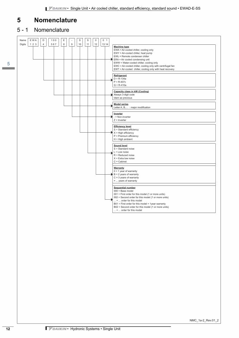
Name E W A D 1 0 0 E - S S 0 0 1
Digits 1 2 3 4 5 6 7 8 9 10 11 12 13 14
Machine type
EWA = Air-cooled chiller, cooling only
EWY = Air-cooled chiller, heat pump
EWL = Remote condenser chiller
ERA = Air cooled condensing unit
EWW = Water-cooled chiller, cooling only
EWC = Air-cooled chiller, cooling only with centrifugal fan
EWT = Air-cooled chiller, cooling only with heat recovery
Refrigerant
D = R-134a
P = R-407c
Q = R-410a
Capacity class in kW (Cooling)
Always 3-digit code
Idem as previous
Model series
Letter A, B,… : major modification
Inverter
- = Non-inverter
Z = Inverter
Efficiency level
S = Standard effi ciency
X = High effi ciency
P = Premium effi ciency
H = High ambient
Sound level
S = Standard noise
L = Low noise
R = Reduced noise
X = Extra low noise
C = Cabinet
Warranty
0 = 1 year of warranty
B = 2 years of warranty
C = 3 years of warranty
= ... years of warranty
Sequential number
000 = Base model
001 = First order for this model (1 or more units)
002 = Second order for this model (1 or more units)
... = ... order for this model
B01 = First order for this model + 1year warranty
B02 = Second order for this model (1 or more units)
... = ... order for this model
NMC_1a-2_Rev.01_2
3
16
• Hydronic Systems • Single Unit 13
• Single Unit • Air cooled chiller, standard efficiency, standard sound • EWAD-E-SS
6 Options
6 - 1 Options
NOTES
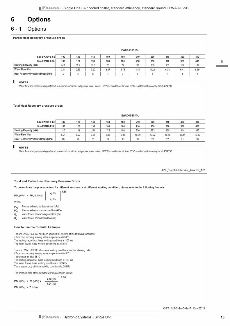
Partial Heat Recovery pressure drops
OPT_1-2-3-4a-5-6a-7_Rev.02_1-2
Size EWAD~E-SS 100 120 140 160 180 210 260 310 360 410
Size EWAD~E-SL 100 120 130 160 180 210 250 300 350 400
Heating Capacity (kW) 44.2 52.9 60.8 70 79 92 109 133 134 134
Water Flow (l/s) 2.11 2.53 2.90 3.37 3.78 4.41 5.22 6.33 6.41 6.39
Heat Recovery Pressure Drops (kPa) 5 6 6 7 7 8 4 5 4 3
EWAD~E-SS / SL
Water fl ow and pressure drop referred to nominal condition: evaporator water in/out: 12/7°C – condenser air inlet 35°C – water heat recovery in/out 40/45°C
NOTES
Total Heat Recovery pressure drops
Size EWAD~E-SS 100 120 140 160 180 210 260 310 360 410
Size EWAD~E-SL 100 120 130 160 180 210 250 300 350 400
Heating Capacity (kW) 110 131 151 175 196 230 273 330 344 343
Water Flow (l/s) 5.24 6.27 7.21 8.36 9.38 10.99 13.02 15.78 16.44 16.39
Heat Recovery Pressure Drops (kPa) 26 29 33 34 36 39 23 27 21 18
EWAD~E-SS / SL
Water fl ow and pressure drop referred to nominal condition: evaporator water in/out: 12/7°C – condenser air inlet 35°C – water heat recovery in/out 40/45°C
OPT_1-2-3-4a-5-6a-7_Rev.02_3
Total and Partial Heat Recovery Pressure Drops
To determinate the pressure drop for different versions or at different working condition, please refer to the following formula:
PD2
(kPa) = PD1
(kPa) x
1.80
where:
Q2 (l/s)
Q1 (l/s)
PD2
Pressure drop to be determinate (kPa)
PD1
Pressure drop at nominal condition (kPa)
Q2
water fl ow at new working condition (l/s)
Q1
water fl ow at nominal condition (l/s)
How to use the formula: Example
The unit EWAD100E-SS has been selected for working at the following conditions:
- Total heat recovery leaving water temperature 40/50°C
The heating capacity at these working conditions is: 106 kW
The water fl ow at these working conditions is: 2.53 l/s
The unit EWAD100E-SS at nominal working conditions has the following data:
- Total heat recovery leaving water temperature 40/45°C
- condenser air inlet: 35°C
The heating capacity at these working conditions is: 110 kW
The water fl ow at these working conditions is: 5.24 l/s
The pressure drop at these working conditions is: 26 kPa
The pressure drop at the selected working condition will be:
PD2
(kPa) = 26 (kPa) x
1.80
PD2
(kPa) = 7 (kPa)
2.53 (l/s)
5.24 (l/s)
• Single Unit • Air cooled chiller, standard efficiency, standard sound • EWAD-E-SS
16
• Hydronic Systems • Single Unit14
6 Options
6 - 1 Options
OPT_1-2-3-4a-5-6a-7_Rev.02_4-5
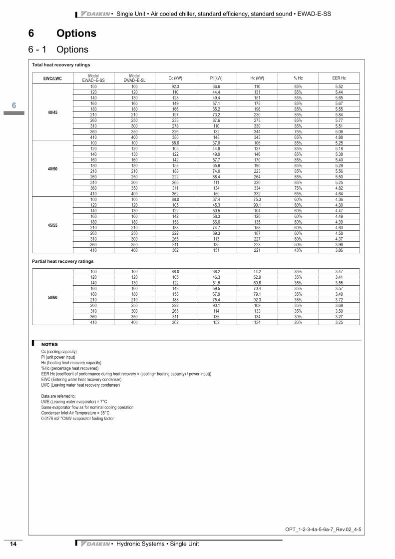
EWC/LWCModel
EWAD~E-SS
Model
EWAD~E-SLCc (kW) Pi (kW) Hc (kW) % Hc EER Hc
40/45
100 100 92.3 36.6 110 85% 5.52
120 120 110 44.4 131 85% 5.44
140 130 128 49.4 151 85% 5.65
160 160 149 57.1 175 85% 5.67
180 180 166 65.2 196 85% 5.55
210 210 197 73.2 230 85% 5.84
260 250 233 87.6 273 85% 5.77
310 300 278 110 330 85% 5.51
360 350 326 132 344 75% 5.06
410 400 380 148 343 65% 4.88
40/50
100 100 88.0 37.0 106 85% 5.25
120 120 105 44.8 127 85% 5.18
140 130 122 49.9 146 85% 5.38
160 160 142 57.7 170 85% 5.40
180 180 158 65.9 190 85% 5.29
210 210 188 74.0 223 85% 5.56
260 250 222 88.4 264 85% 5.50
310 300 265 111 320 85% 5.25
360 350 311 134 334 75% 4.82
410 400 362 150 332 65% 4.64
45/55
100 100 88.0 37.4 75.3 60% 4.36
120 120 105 45.3 90.1 60% 4.30
140 130 122 50.5 104 60% 4.47
160 160 142 58.3 120 60% 4.49
180 180 158 66.6 135 60% 4.39
210 210 188 74.7 158 60% 4.63
260 250 222 89.3 187 60% 4.58
310 300 265 113 227 60% 4.37
360 350 311 135 223 50% 3.96
410 400 362 151 221 43% 3.86
NOTES
Cc (cooling capacity)
Pi (unit power input)
Hc (heating heat recovery capacity)
%Hc (percentage heat recovered)
EER Hc (coeffi cent of performance during heat recovery = (cooling+ heating capacity) / power input))
EWC (Entering water heat recovery condenser)
LWC (Leaving water heat recovery condenser)
Data are referred to:
LWE (Leaving water evaporator) = 7°C
Same evaporator fl ow as for nominal cooling operation
Condenser Inlet Air Temperature = 35°C
0.0176 m2 °C/kW evaporator fouling factor
Total heat recovery ratings
Partial heat recovery ratings
50/60
100 100 88.0 38.2 44.2 35% 3.47
120 120 105 46.3 52.9 35% 3.41
140 130 122 51.5 60.8 35% 3.55
160 160 142 59.5 70.4 35% 3.57
180 180 158 67.9 79.1 35% 3.49
210 210 188 75.4 92.3 35% 3.72
260 250 222 90.1 109 35% 3.68
310 300 265 114 133 35% 3.50
360 350 311 136 134 30% 3.27
410 400 362 152 134 26% 3.25
3
16
• Hydronic Systems • Single Unit 15
• Single Unit • Air cooled chiller, standard efficiency, standard sound • EWAD-E-SS
6 Options
6 - 1 Options
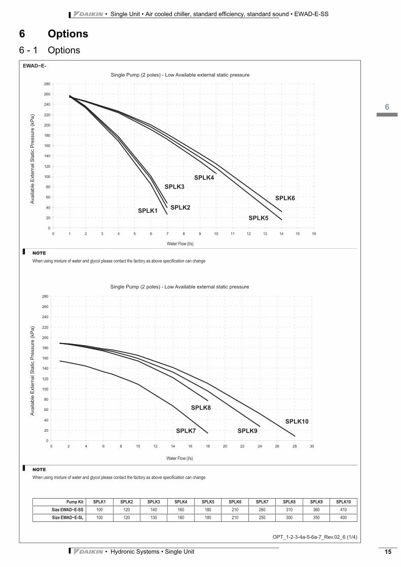
EWAD~E-
OPT_1-2-3-4a-5-6a-7_Rev.02_6 (1/4)
Ava
ila
ble
Exte
rna
l S
tatic P
ressu
re (
kP
a)
Single Pump (2 poles) - Low Available external static pressure
0
20
40
60
80
100
120
140
160
180
200
220
240
260
280
0 1 2 3 4 5 6 7 8 9 10 11 12 13 14 15 16
SPLK1
SPLK4
SPLK5
SPLK6
SPLK2
SPLK3
Water Flow (l/s)
NOTE
When using mixture of water and glycol please contact the factory as above specifi cation can change
Ava
ila
ble
Exte
rna
l S
tatic P
ressu
re (
kP
a)
Single Pump (2 poles) - Low Available external static pressure
0
20
40
60
80
100
120
140
160
180
200
220
240
260
280
0 2 4 6 8 10 12 14 16 18 20 22 24 26 28 30
SPLK7
SPLK8
SPLK9
SPLK10
Water Flow (l/s)
NOTE
When using mixture of water and glycol please contact the factory as above specifi cation can change
Pump Kit SPLK1 SPLK2 SPLK3 SPLK4 SPLK5 SPLK6 SPLK7 SPLK8 SPLK9 SPLK10
Size EWAD~E-SS 100 120 140 160 180 210 260 310 360 410
Size EWAD~E-SL 100 120 130 160 180 210 250 300 350 400
• Single Unit • Air cooled chiller, standard efficiency, standard sound • EWAD-E-SS
16
• Hydronic Systems • Single Unit16
6 Options
6 - 1 Options
EWAD~E-
OPT_1-2-3-4a-5-6a-7_Rev.02_6 (2/4)
Ava
ila
ble
Exte
rna
l S
tatic P
ressu
re (
kP
a)
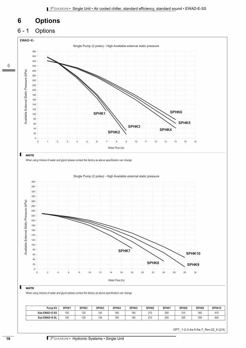
Single Pump (2 poles) - High Available external static pressure
0
20
40
60
80
100
120
140
160
180
200
220
240
260
280
300
320
340
360
0 1 2 3 4 5 6 7 8 9 10 11 12 13 14 15 16
SPHK1
SPHK2
SPHK3SPHK4
SPHK5
SPHK6
Water Flow (l/s)
NOTE
When using mixture of water and glycol please contact the factory as above specifi cation can change
Ava
ila
ble
Exte
rna
l S
tatic P
ressu
re (
kP
a)
Single Pump (2 poles) - High Available external static pressure
0
20
40
60
80
100
120
140
160
180
200
220
240
260
280
300
320
340
360
0 2 4 6 8 10 12 14 16 18 20 22 24 26 28 30
SPHK7
SPHK8SPHK9
SPHK10
Water Flow (l/s)
NOTE
When using mixture of water and glycol please contact the factory as above specifi cation can change
Pump Kit SPHK1 SPHK2 SPHK3 SPHK4 SPHK5 SPHK6 SPHK7 SPHK8 SPHK9 SPHK10
Size EWAD~E-SS 100 120 140 160 180 210 260 310 360 410
Size EWAD~E-SL 100 120 130 160 180 210 250 300 350 400
3
16
• Hydronic Systems • Single Unit 17
• Single Unit • Air cooled chiller, standard efficiency, standard sound • EWAD-E-SS
6 Options
6 - 1 Options
EWAD~E-
OPT_1-2-3-4a-5-6a-7_Rev.02_6 (3/4)
Ava
ila
ble
Exte
rna
l S
tatic P
ressu
re (
kP
a)
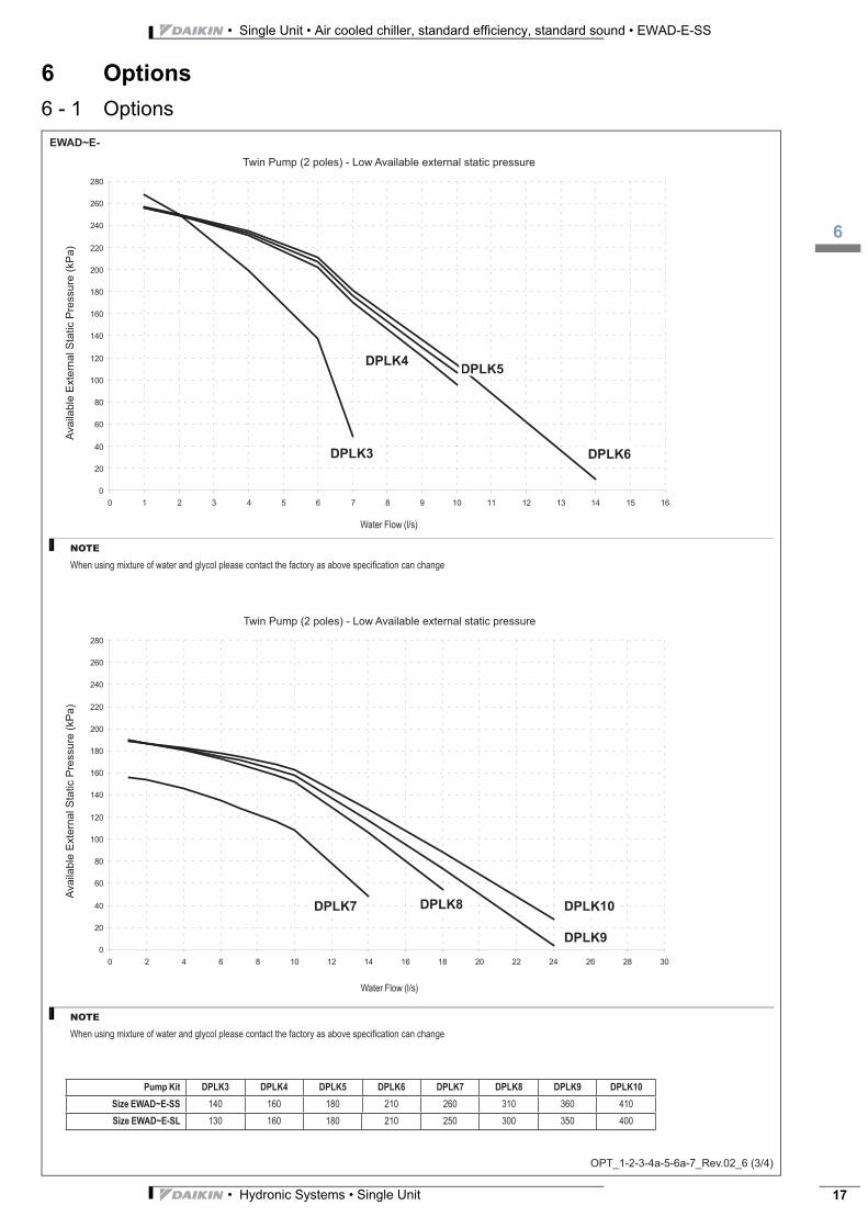
Twin Pump (2 poles) - Low Available external static pressure
0
20
40
60
80
100
120
140
160
180
200
220
240
260
280
0 1 2 3 4 5 6 7 8 9 10 11 12 13 14 15 16
DPLK3
DPLK4DPLK5
DPLK6
Water Flow (l/s)
NOTE
When using mixture of water and glycol please contact the factory as above specifi cation can change
Ava
ila
ble
Exte
rna
l S
tatic P
ressu
re (
kP
a)
Twin Pump (2 poles) - Low Available external static pressure
0
20
40
60
80
100
120
140
160
180
200
220
240
260
280
0 2 4 6 8 10 12 14 16 18 20 22 24 26 28 30
DPLK7 DPLK8
DPLK9
DPLK10
Water Flow (l/s)
NOTE
When using mixture of water and glycol please contact the factory as above specifi cation can change
Pump Kit DPLK3 DPLK4 DPLK5 DPLK6 DPLK7 DPLK8 DPLK9 DPLK10
Size EWAD~E-SS 140 160 180 210 260 310 360 410
Size EWAD~E-SL 130 160 180 210 250 300 350 400
• Single Unit • Air cooled chiller, standard efficiency, standard sound • EWAD-E-SS
16
• Hydronic Systems • Single Unit18
6 Options
6 - 1 Options
EWAD~E-
OPT_1-2-3-4a-5-6a-7_Rev.02_6 (4/4)
Ava
ila
ble
Exte
rna
l S
tatic P
ressu
re (
kP
a)
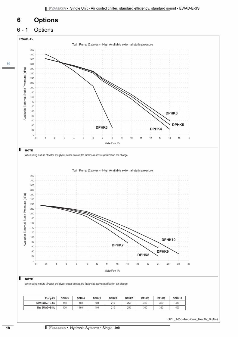
Twin Pump (2 poles) - High Available external static pressure
0
20
40
60
80
100
120
140
160
180
200
220
240
260
280
300
320
340
360
0 1 2 3 4 5 6 7 8 9 10 11 12 13 14 15 16
DPHK3DPHK4
DPHK5
DPHK6
Water Flow (l/s)
NOTE
When using mixture of water and glycol please contact the factory as above specifi cation can change
Ava
ila
ble
Exte
rna
l S
tatic P
ressu
re (
kP
a)
Twin Pump (2 poles) - High Available external static pressure
0
20
40
60
80
100
120
140
160
180
200
220
240
260
280
300
320
340
360
0 2 4 6 8 10 12 14 16 18 20 22 24 26 28 30
DPHK7
DPHK8
DPHK10
DPHK9
Water Flow (l/s)
NOTE
When using mixture of water and glycol please contact the factory as above specifi cation can change
Pump Kit DPHK3 DPHK4 DPHK5 DPHK6 DPHK7 DPHK8 DPHK9 DPHK10
Size EWAD~E-SS 140 160 180 210 260 310 360 410
Size EWAD~E-SL 130 160 180 210 250 300 350 400
3
16
• Hydronic Systems • Single Unit 19
• Single Unit • Air cooled chiller, standard efficiency, standard sound • EWAD-E-SS
6 Options
6 - 1 Options
EWAD~E-
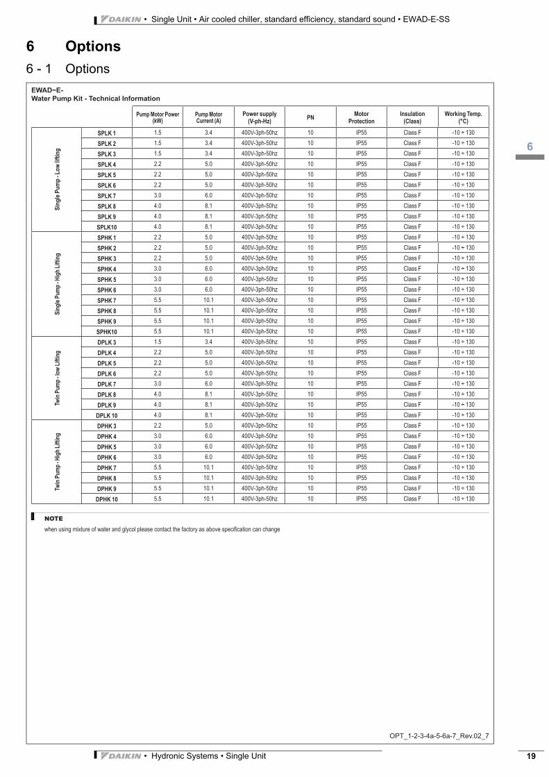
Water Pump Kit - Technical Information
OPT_1-2-3-4a-5-6a-7_Rev.02_7
Pump Motor Power
(kW)
Pump Motor
Current (A)
Power supply
(V-ph-Hz)PN
Motor
Protection
Insulation
(Class)
Working Temp.
(°C)
Sin
gle
Pu
mp
- L
ow
lif
tin
g
SPLK 1 1.5 3.4 400V-3ph-50hz 10 IP55 Class F -10 ÷ 130
SPLK 2 1.5 3.4 400V-3ph-50hz 10 IP55 Class F -10 ÷ 130
SPLK 3 1.5 3.4 400V-3ph-50hz 10 IP55 Class F -10 ÷ 130
SPLK 4 2.2 5.0 400V-3ph-50hz 10 IP55 Class F -10 ÷ 130
SPLK 5 2.2 5.0 400V-3ph-50hz 10 IP55 Class F -10 ÷ 130
SPLK 6 2.2 5.0 400V-3ph-50hz 10 IP55 Class F -10 ÷ 130
SPLK 7 3.0 6.0 400V-3ph-50hz 10 IP55 Class F -10 ÷ 130
SPLK 8 4.0 8.1 400V-3ph-50hz 10 IP55 Class F -10 ÷ 130
SPLK 9 4.0 8.1 400V-3ph-50hz 10 IP55 Class F -10 ÷ 130
SPLK10 4.0 8.1 400V-3ph-50hz 10 IP55 Class F -10 ÷ 130
Sin
gle
Pu
mp
- H
igh
Lif
tin
g
SPHK 1 2.2 5.0 400V-3ph-50hz 10 IP55 Class F -10 ÷ 130
SPHK 2 2.2 5.0 400V-3ph-50hz 10 IP55 Class F -10 ÷ 130
SPHK 3 2.2 5.0 400V-3ph-50hz 10 IP55 Class F -10 ÷ 130
SPHK 4 3.0 6.0 400V-3ph-50hz 10 IP55 Class F -10 ÷ 130
SPHK 5 3.0 6.0 400V-3ph-50hz 10 IP55 Class F -10 ÷ 130
SPHK 6 3.0 6.0 400V-3ph-50hz 10 IP55 Class F -10 ÷ 130
SPHK 7 5.5 10.1 400V-3ph-50hz 10 IP55 Class F -10 ÷ 130
SPHK 8 5.5 10.1 400V-3ph-50hz 10 IP55 Class F -10 ÷ 130
SPHK 9 5.5 10.1 400V-3ph-50hz 10 IP55 Class F -10 ÷ 130
SPHK10 5.5 10.1 400V-3ph-50hz 10 IP55 Class F -10 ÷ 130
Tw
in P
um
p - lo
w L
ifti
ng
DPLK 3 1.5 3.4 400V-3ph-50hz 10 IP55 Class F -10 ÷ 130
DPLK 4 2.2 5.0 400V-3ph-50hz 10 IP55 Class F -10 ÷ 130
DPLK 5 2.2 5.0 400V-3ph-50hz 10 IP55 Class F -10 ÷ 130
DPLK 6 2.2 5.0 400V-3ph-50hz 10 IP55 Class F -10 ÷ 130
DPLK 7 3.0 6.0 400V-3ph-50hz 10 IP55 Class F -10 ÷ 130
DPLK 8 4.0 8.1 400V-3ph-50hz 10 IP55 Class F -10 ÷ 130
DPLK 9 4.0 8.1 400V-3ph-50hz 10 IP55 Class F -10 ÷ 130
DPLK 10 4.0 8.1 400V-3ph-50hz 10 IP55 Class F -10 ÷ 130
Tw
in P
um
p - H
igh
Lif
tin
g
DPHK 3 2.2 5.0 400V-3ph-50hz 10 IP55 Class F -10 ÷ 130
DPHK 4 3.0 6.0 400V-3ph-50hz 10 IP55 Class F -10 ÷ 130
DPHK 5 3.0 6.0 400V-3ph-50hz 10 IP55 Class F -10 ÷ 130
DPHK 6 3.0 6.0 400V-3ph-50hz 10 IP55 Class F -10 ÷ 130
DPHK 7 5.5 10.1 400V-3ph-50hz 10 IP55 Class F -10 ÷ 130
DPHK 8 5.5 10.1 400V-3ph-50hz 10 IP55 Class F -10 ÷ 130
DPHK 9 5.5 10.1 400V-3ph-50hz 10 IP55 Class F -10 ÷ 130
DPHK 10 5.5 10.1 400V-3ph-50hz 10 IP55 Class F -10 ÷ 130
NOTE
when using mixture of water and glycol please contact the factory as above specifi cation can change
• Single Unit • Air cooled chiller, standard efficiency, standard sound • EWAD-E-SS
17
• Hydronic Systems • Single Unit20
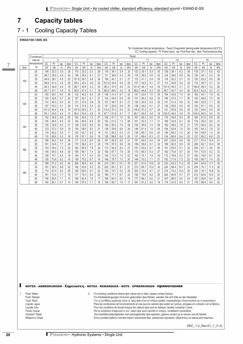
7 Capacity tables
7 - 1 Cooling Capacity Tables
3
17
• Hydronic Systems • Single Unit 21
• Single Unit • Air cooled chiller, standard efficiency, standard sound • EWAD-E-SS
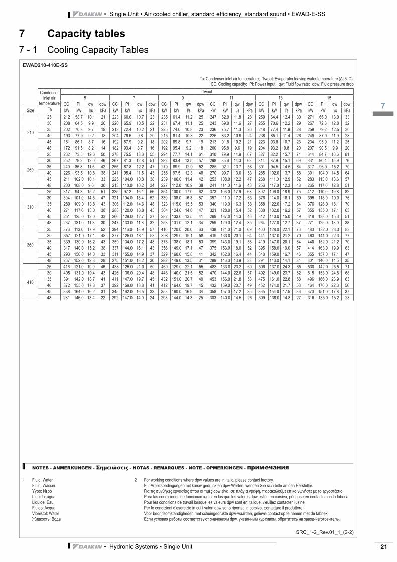
7 Capacity tables
7 - 1 Cooling Capacity Tables
• Single Unit • Air cooled chiller, standard efficiency, standard sound • EWAD-E-SS
18
• Hydronic Systems • Single Unit22
8 Dimensional drawings
8 - 1 Dimensional Drawings
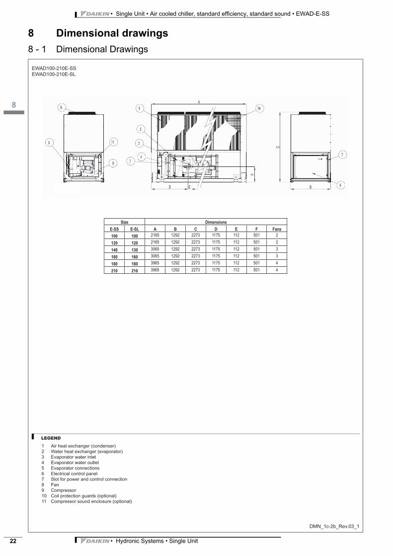
EWAD100-210E-SS
EWAD100-210E-SL
DMN_1c-2b_Rev.03_1
1 Air heat exchanger (condenser)
2 Water heat exchanger (evaporator)
3 Evaporator water inlet
4 Evaporator water outlet
5 Evaporator connections
6 Electrical control panel
7 Slot for power and control connection
8 Fan
9 Compressor
10 Coil protection guards (optional)
11 Compressor sound enclosure (optional)
Size Dimensions
E-SS E-SL A B C D E F Fans
100 100 2165 1292 2273 1175 112 501 2
120 120 2165 1292 2273 1175 112 501 2
140 130 3065 1292 2273 1175 112 501 3
160 160 3065 1292 2273 1175 112 501 3
180 180 3965 1292 2273 1175 112 501 4
210 210 3965 1292 2273 1175 112 501 4
LEGEND
3
18
• Hydronic Systems • Single Unit 23
• Single Unit • Air cooled chiller, standard efficiency, standard sound • EWAD-E-SS
8 Dimensional drawings
8 - 1 Dimensional Drawings
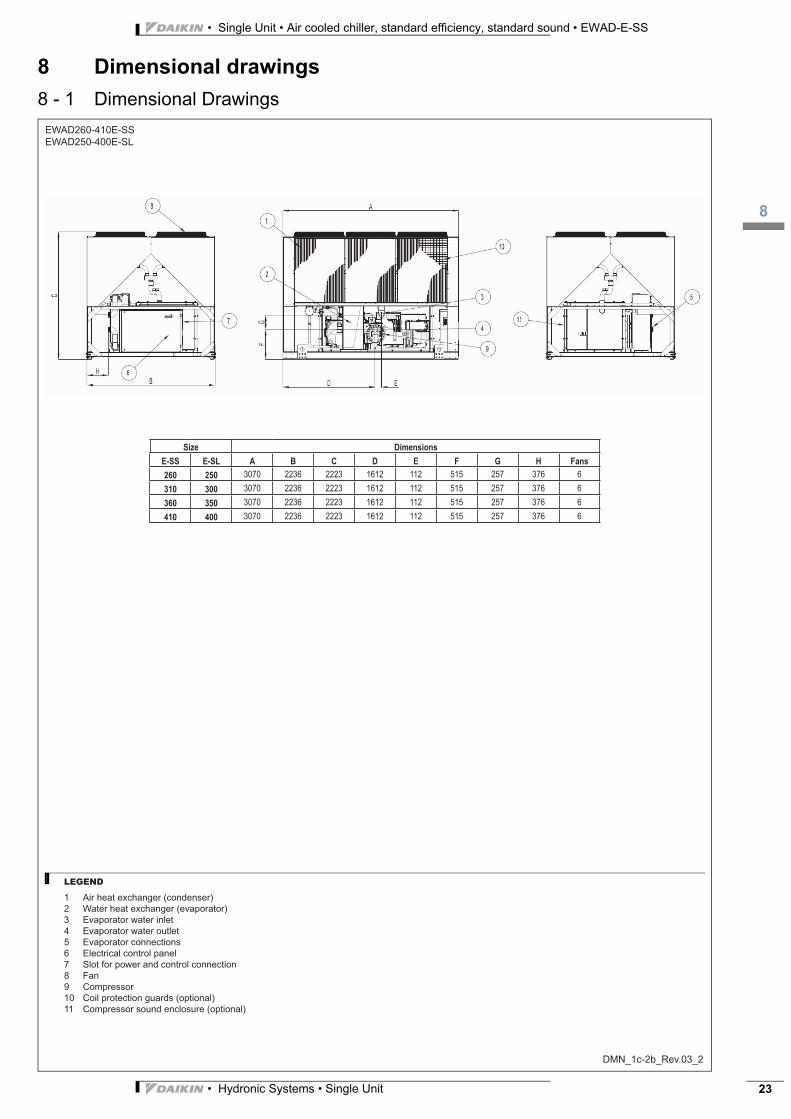
EWAD260-410E-SS
EWAD250-400E-SL
DMN_1c-2b_Rev.03_2
1 Air heat exchanger (condenser)
2 Water heat exchanger (evaporator)
3 Evaporator water inlet
4 Evaporator water outlet
5 Evaporator connections
6 Electrical control panel
7 Slot for power and control connection
8 Fan
9 Compressor
10 Coil protection guards (optional)
11 Compressor sound enclosure (optional)
Size Dimensions
E-SS E-SL A B C D E F G H Fans
260 250 3070 2236 2223 1612 112 515 257 376 6
310 300 3070 2236 2223 1612 112 515 257 376 6
360 350 3070 2236 2223 1612 112 515 257 376 6
410 400 3070 2236 2223 1612 112 515 257 376 6
LEGEND
• Single Unit • Air cooled chiller, standard efficiency, standard sound • EWAD-E-SS
19
• Hydronic Systems • Single Unit24
9 Sound data
9 - 1 Sound Level Data
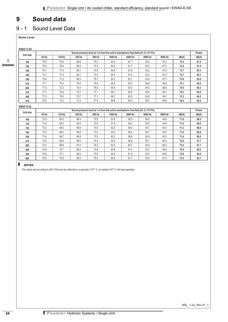
Noise Level
NSL_1-2a_Rev.01_1
EWAD~E-SS
Unit sizeSound pressure level at 1 m from the unit in semispheric free field (rif. 2 x 10⁻⁵ Pa) Power
63 Hz 125 Hz 250 Hz 500 Hz 1000 Hz 2000 Hz 4000 Hz 8000 Hz dB(A) dB(A)
100 75.5 70.8 68.9 75.3 64.3 61.7 53.0 47.3 73.5 91.5
120 75.5 70.8 68.9 75.3 64.3 61.7 53.0 47.3 73.5 91.5
140 75.7 71.0 69.1 75.5 64.5 61.9 53.2 47.5 73.7 92.3
160 75.7 71.0 69.1 75.5 64.5 61.9 53.2 47.5 73.7 92.3
180 75.9 71.2 69.3 75.7 64.7 62.1 53.4 47.7 73.9 93.0
210 77.1 72.4 70.5 76.9 65.9 63.3 54.6 48.9 75.1 94.2
260 77.0 72.3 70.4 76.8 65.8 63.2 54.5 48.8 75.0 94.2
310 77.3 72.6 70.7 77.1 66.1 63.5 54.8 49.1 75.3 94.5
360 77.3 72.6 70.7 77.1 66.1 63.5 54.8 49.1 75.3 94.5
410 78.0 73.3 71.4 77.8 66.8 64.2 55.5 49.8 76.0 95.2
EWAD~E-SL
Unit sizeSound pressure level at 1 m from the unit in semispheric free fi eld (rif. 2 x 10⁻⁵ Pa) Power
63 Hz 125 Hz 250 Hz 500 Hz 1000 Hz 2000 Hz 4000 Hz 8000 Hz dB(A) dB(A)
100 73.0 68.3 66.4 72.8 61.8 59.2 50.5 44.8 71.0 89.0
120 73.0 68.3 66.4 72.8 61.8 59.2 50.5 44.8 71.0 89.0
130 73.2 68.5 66.6 73.0 62.0 59.4 50.7 45.0 71.2 89.8
160 73.2 68.5 66.6 73.0 62.0 59.4 50.7 45.0 71.2 89.8
180 73.4 68.7 66.8 73.2 62.2 59.6 50.9 45.2 71.4 90.5
210 74.6 69.9 68.0 74.4 63.4 60.8 52.1 46.4 72.6 91.7
250 74.5 69.8 67.9 74.3 63.3 60.7 52.0 46.3 72.5 91.7
300 74.8 70.1 68.2 74.6 63.6 61.0 52.3 46.6 72.8 92.0
350 74.8 70.1 68.2 74.6 63.6 61.0 52.3 46.6 72.8 92.0
400 75.5 70.8 68.9 75.3 64.3 61.7 53.0 47.3 73.5 92.7
NOTES
The values are according to ISO 3744 and are referred to: evaporator 12/7° C. air ambient 35° C. full load operation
3
19
• Hydronic Systems • Single Unit 25
• Single Unit • Air cooled chiller, standard efficiency, standard sound • EWAD-E-SS
9 Sound data
9 - 1 Sound Level Data
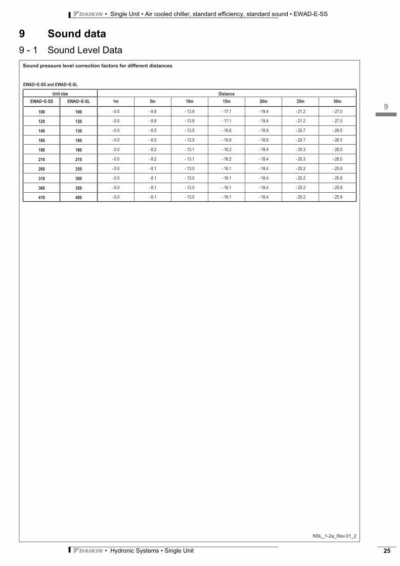
Sound pressure level correction factors for different distances
NSL_1-2a_Rev.01_2
EWAD~E-SS and EWAD~E-SL
Unit size Distance
EWAD~E-SS EWAD~E-SL 1m 5m 10m 15m 20m 25m 50m
100 100 - 0.0 - 8.8 - 13.9 - 17.1 - 19.4 - 21.2 - 27.0
120 120 - 0.0 - 8.8 - 13.9 - 17.1 - 19.4 - 21.2 - 27.0
140 130 - 0.0 - 8.5 - 13.5 - 16.6 - 18.9 - 20.7 - 26.5
160 160 - 0.0 - 8.5 - 13.5 - 16.6 - 18.9 - 20.7 - 26.5
180 180 - 0.0 - 8.2 - 13.1 - 16.2 - 18.4 - 20.3 - 26.0
210 210 - 0.0 - 8.2 - 13.1 - 16.2 - 18.4 - 20.3 - 26.0
260 250 - 0.0 - 8.1 - 13.0 - 16.1 - 18.4 - 20.2 - 25.9
310 300 - 0.0 - 8.1 - 13.0 - 16.1 - 18.4 - 20.2 - 25.9
360 350 - 0.0 - 8.1 - 13.0 - 16.1 - 18.4 - 20.2 - 25.9
410 400 - 0.0 - 8.1 - 13.0 - 16.1 - 18.4 - 20.2 - 25.9
• Single Unit • Air cooled chiller, standard efficiency, standard sound • EWAD-E-SS
110
• Hydronic Systems • Single Unit26
10 Installation
10 - 1 Installation Method
INN_1a-2a-3-4_Rev.01_1
Installation notes
Warning
Installation and maintenance of the unit must to be performed only by qualified personnel who have knowledge with local
codes and regulations, and experience with this type of equipment. The unit must be installed to allow all the maintenance
operations.
Handling
Care should be taken to avoid rough handling or shock due to dropping the unit. Do not push or pull the unit from anything
other than the base frame. Never allow the unit to fall during unloading or moving as this may result in serious damage. To lift
the unit, rings are provided in the base frame of the unit. Spreader bar and cables should be arranged to prevent damage to
the condenser coil or unit cabinet.
Location
The units are produced for outside installation on roofs, floors or below ground level on condition that the area is free from
obstacles for the passage of the condenser air. The unit should be positioned on solid foundations and perfectly level; in the
case of installation on roofs or floors, it may be advisable to arrange the use of suitable weight distribution beams. When the
units are installed on the ground, a concrete base at least 250 mm wider and longer than the unit’s footprint should be laid.
Furthermore, this base should withstand the unit weight mentioned in the technical data table.
Space requirements
The units are air-cooled, then it is important to respect the minimum distances which guarantee the best ventilation of the
condenser coils. Limitations of space reducing the air flow could cause significant reductions in cooling capacity and an
increase in electricity consumption.
To determinate unit placement, careful consideration must be given to assure a sufficient air flow across the condenser heat
transfer surface. Two conditions must be avoided to achieve the best performance: warm air recirculation and coil starvation.
Both these conditions cause an increase of condensing pressures that result in reductions in unit efficiency and capacity.
Moreover the unique microprocessor has the ability to analyse the operating environment of the air cooled chiller and to
optimize its performance staying on-line during abnormal conditions.
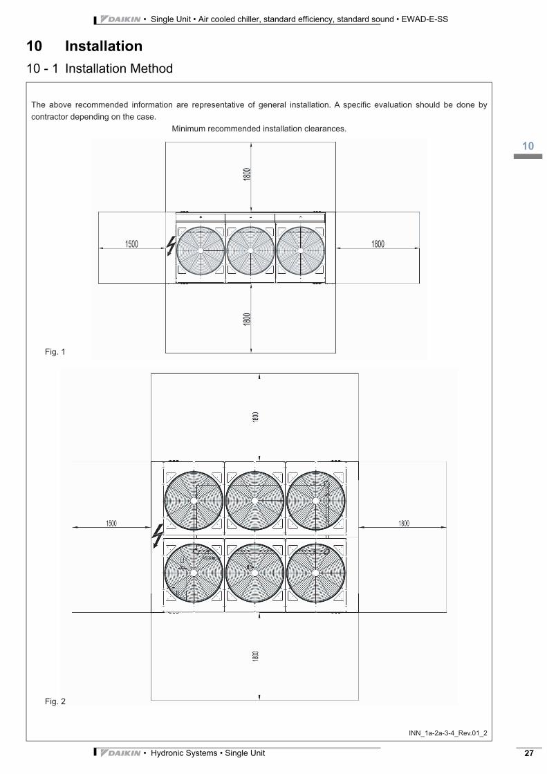
Each side of the unit must be accessible after installation for periodic service. Fig.1 and 2 show you minimum recommended
clearance requirements.
Vertical condenser air discharge must be unobstructed because the unit would have its capacity and efficiency significantly
reduced.
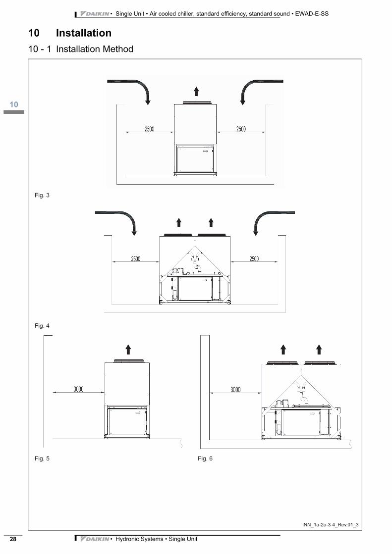
If the units are positioned in places surrounded by walls or obstacles of the same height as the units, the units should be at
least 2500 mm from obstacles (fig.3 and 4). In the event the obstacles are higher than the units, the units should be at least
3000 mm from the obstacle (fig.5 and 6). Units installed closer than the minimum recommended distance to a wall or other
vertical riser may experience a combination of coil starvation and warm air recirculation, thus causing reduction in unit capacity
and efficiency reductions. The microprocessor control is proactive in response “of design condition”. In the case of single
or compounded influences restricting airflow to the unit, the microprocessor will act to keep the compressor(s) running (at
reduced capacity) rather than allowing a shut-off on high discharge pressure.
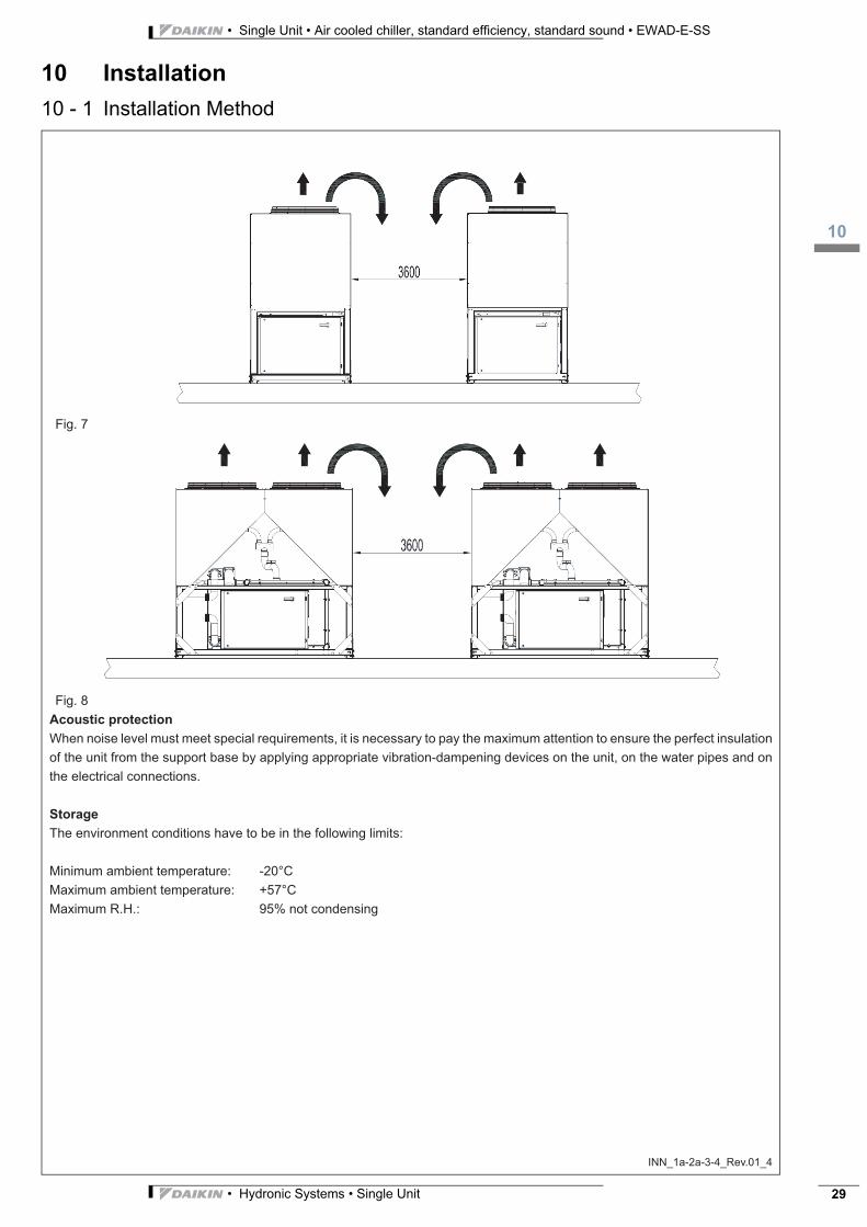
When two or more units are positioned side by side it is recommended that the condenser coils are at least 3600 mm distance
from one another (fig.7 and 8); strong wind could be the cause of air warm recirculation.
For other installation solutions, consult our technicians.
3
110
• Hydronic Systems • Single Unit 27
• Single Unit • Air cooled chiller, standard efficiency, standard sound • EWAD-E-SS
10 Installation
10 - 1 Installation Method
INN_1a-2a-3-4_Rev.01_2
The above recommended information are representative of general installation. A specific evaluation should be done by
contractor depending on the case.
Minimum recommended installation clearances.
Fig. 1
Fig. 2
• Single Unit • Air cooled chiller, standard efficiency, standard sound • EWAD-E-SS
110
• Hydronic Systems • Single Unit28
10 Installation
10 - 1 Installation Method
INN_1a-2a-3-4_Rev.01_3
Fig. 3
Fig. 4
Fig. 5 Fig. 6
3
110
• Hydronic Systems • Single Unit 29
• Single Unit • Air cooled chiller, standard efficiency, standard sound • EWAD-E-SS
10 Installation
10 - 1 Installation Method
INN_1a-2a-3-4_Rev.01_4
Fig. 7
Fig. 8
Acoustic protection
When noise level must meet special requirements, it is necessary to pay the maximum attention to ensure the perfect insulation
of the unit from the support base by applying appropriate vibration-dampening devices on the unit, on the water pipes and on
the electrical connections.
Storage
The environment conditions have to be in the following limits:
Minimum ambient temperature: -20°C
Maximum ambient temperature: +57°C
Maximum R.H.: 95% not condensing
• Single Unit • Air cooled chiller, standard efficiency, standard sound • EWAD-E-SS
111
• Hydronic Systems • Single Unit30
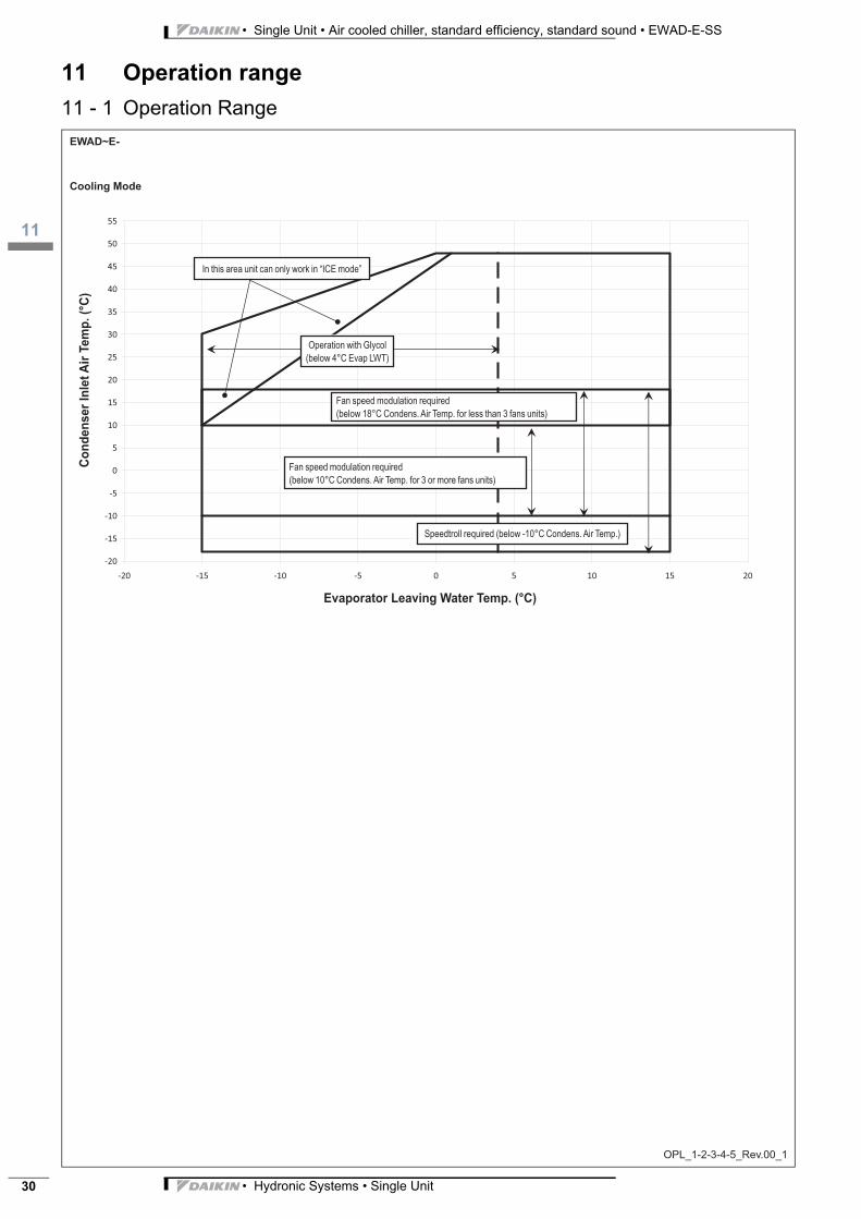
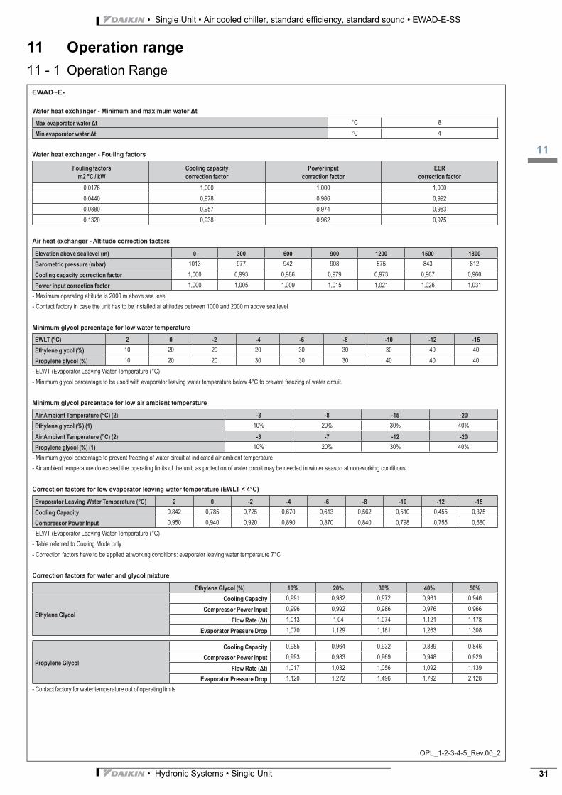
11 Operation range
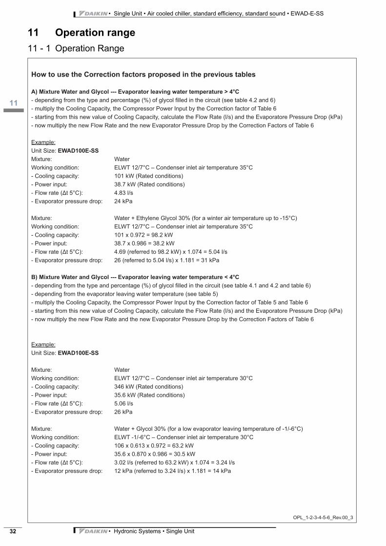
11 - 1 Operation Range
-20
-15
-10
-5
0
5
10
15
20
25
30
35
40
45
50
55
-20 -15 -10 -5 0 5 10 15 20
3
111
• Hydronic Systems • Single Unit 31
• Single Unit • Air cooled chiller, standard efficiency, standard sound • EWAD-E-SS
11 Operation range
11 - 1 Operation Range
• Single Unit • Air cooled chiller, standard efficiency, standard sound • EWAD-E-SS
111
• Hydronic Systems • Single Unit32
11 Operation range
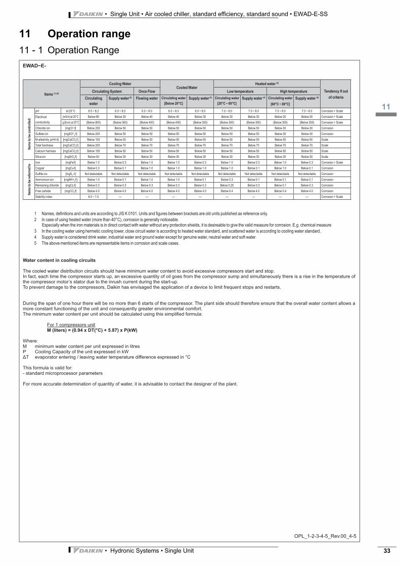
11 - 1 Operation Range
3
111
• Hydronic Systems • Single Unit 33
• Single Unit • Air cooled chiller, standard efficiency, standard sound • EWAD-E-SS
11 Operation range
11 - 1 Operation Range
• Single Unit • Air cooled chiller, standard efficiency, standard sound • EWAD-E-SS
112
• Hydronic Systems • Single Unit34
12 Hydraulic performance
12 - 1 Water Pressure Drop Curve Evaporator
EPD_1-2_Rev.00_1
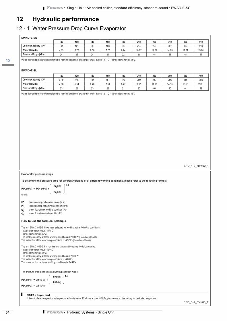
100 120 140 160 180 210 260 310 360 410
Cooling Capacity (kW) 101 121 138 163 183 214 256 307 360 413
Water Flow (l/s) 4.83 5.76 6.58 7.77 8.74 10.22 12.22 14.65 17.21 19.74
Pressure Drops (kPa) 24 25 24 24 22 21 48 48 48 45
100 120 130 160 180 210 250 300 350 400
Cooling Capacity (kW) 97.9 116 134 157 177 209 249 296 345 398
Water Flow (l/s) 4.68 5.54 6.40 7.51 8.47 9.97 11.90 14.15 16.50 19.01
Pressure Drops (kPa) 23 23 23 23 21 20 46 45 44 42
EWAD~E-SS
EWAD~E-SL
Water fl ow and pressure drop referred to nominal condition: evaporator water in/out: 12/7°C – condenser air inlet: 35°C
Water fl ow and pressure drop referred to nominal condition: evaporator water in/out: 12/7°C – condenser air inlet: 35°C
EPD_1-2_Rev.00_2
Evaporator pressure drops
To determine the pressure drop for different versions or at different working conditions, please refer to the following formula:
PD2
(kPa) = PD1
(kPa) x
1.8
where:
Q2(l/s)
Q1(l/s)
PD2
Pressure drop to be determinate (kPa)
PD1
Pressure drop at nominal condition (kPa)
Q2
water fl ow at new working condition (l/s)
Q1
water fl ow at nominal condition (l/s)
How to use the formula: Example
The unit EWAD100E-SS has been selected for working at the following conditions:
- evaporator water in/out : 11/6°C
- condenser air inlet: 30°C
The cooling capacity at these working conditions is: 103 kW (Rated conditions)
The water fl ow at these working conditions is: 4.92 l/s (Rated conditions)
The unit EWAD100E-SS at nominal working conditions has the following data:
- evaporator water in/out : 12/7°C
- condenser air inlet: 35°C
The cooling capacity at these working conditions is: 101 kW
The water fl ow at these working conditions is: 4.83 l/s
The pressure drop at these working conditions is: 24 kPa
The pressure drop at the selected working condition will be:
PD2
(kPa) = 24 (kPa) x
1.8
PD2
(kPa) = 25 (kPa)
4.92 (l/s)
4.83 (l/s)
NOTE - Important
If the calculated evaporator water pressure drop is below 10 kPa or above 100 kPa, please contact the factory for dedicated evaporator.
3
113
• Hydronic Systems • Single Unit 35
• Single Unit • Air cooled chiller, standard efficiency, standard sound • EWAD-E-SS
13 Specification text
13 - 1 Specification Text
SPC_1b-2a-3-4_Rev.02_1
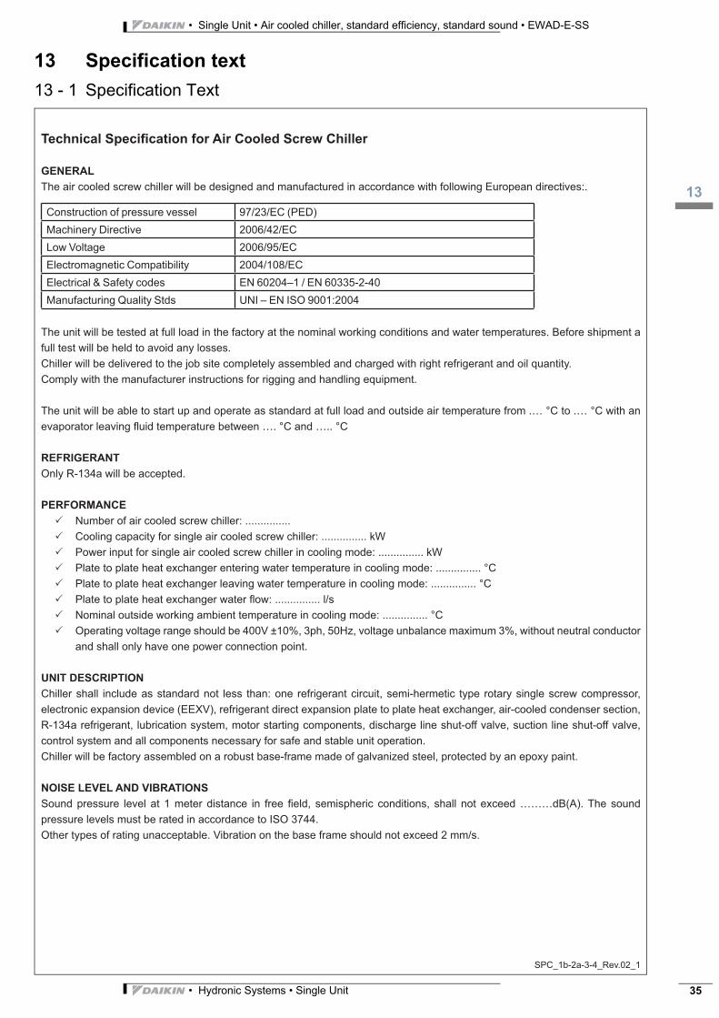
Technical Specifi cation for Air Cooled Screw Chiller
GENERAL
The air cooled screw chiller will be designed and manufactured in accordance with following European directives:.
Construction of pressure vessel 97/23/EC (PED)
Machinery Directive 2006/42/EC
Low Voltage 2006/95/EC
Electromagnetic Compatibility 2004/108/EC
Electrical & Safety codes EN 60204–1 / EN 60335-2-40
Manufacturing Quality Stds UNI – EN ISO 9001:2004
The unit will be tested at full load in the factory at the nominal working conditions and water temperatures. Before shipment a
full test will be held to avoid any losses.
Chiller will be delivered to the job site completely assembled and charged with right refrigerant and oil quantity.
Comply with the manufacturer instructions for rigging and handling equipment.
The unit will be able to start up and operate as standard at full load and outside air temperature from .… °C to .… °C with an
evaporator leaving fl uid temperature between …. °C and ….. °C
REFRIGERANT
Only R-134a will be accepted.
PERFORMANCE
Number of air cooled screw chiller: ...............
Cooling capacity for single air cooled screw chiller: ............... kW
Power input for single air cooled screw chiller in cooling mode: ............... kW
Plate to plate heat exchanger entering water temperature in cooling mode: ............... °C
Plate to plate heat exchanger leaving water temperature in cooling mode: ............... °C
Plate to plate heat exchanger water fl ow: ............... l/s
Nominal outside working ambient temperature in cooling mode: ............... °C
Operating voltage range should be 400V ±10%, 3ph, 50Hz, voltage unbalance maximum 3%, without neutral conductor
and shall only have one power connection point.
UNIT DESCRIPTION
Chiller shall include as standard not less than: one refrigerant circuit, semi-hermetic type rotary single screw compressor,
electronic expansion device (EEXV), refrigerant direct expansion plate to plate heat exchanger, air-cooled condenser section,
R-134a refrigerant, lubrication system, motor starting components, discharge line shut-off valve, suction line shut-off valve,
control system and all components necessary for safe and stable unit operation.
Chiller will be factory assembled on a robust base-frame made of galvanized steel, protected by an epoxy paint.
NOISE LEVEL AND VIBRATIONS
Sound pressure level at 1 meter distance in free fi eld, semispheric conditions, shall not exceed ………dB(A). The sound
pressure levels must be rated in accordance to ISO 3744.
Other types of rating unacceptable. Vibration on the base frame should not exceed 2 mm/s.
• Single Unit • Air cooled chiller, standard efficiency, standard sound • EWAD-E-SS
113
• Hydronic Systems • Single Unit36
13 Specification text
13 - 1 Specification Text
SPC_1b-2a-3-4_Rev.02_2
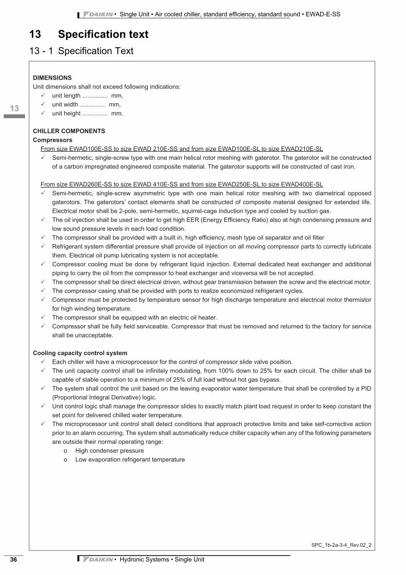
DIMENSIONS
Unit dimensions shall not exceed following indications:
unit length ............... mm,
unit width ............... mm,
unit height ............... mm.
CHILLER COMPONENTS
Compressors
From size EWAD100E-SS to size EWAD 210E-SS and from size EWAD100E-SL to size EWAD210E-SL
Semi-hermetic, single-screw type with one main helical rotor meshing with gaterotor. The gaterotor will be constructed
of a carbon impregnated engineered composite material. The gaterotor supports will be constructed of cast iron.
From size EWAD260E-SS to size EWAD 410E-SS and from size EWAD250E-SL to size EWAD400E-SL
Semi-hermetic, single-screw asymmetric type with one main helical rotor meshing with two diametrical opposed
gaterotors. The gaterotors’ contact elements shall be constructed of composite material designed for extended life.
Electrical motor shall be 2-pole, semi-hermetic, squirrel-cage induction type and cooled by suction gas.
The oil injection shall be used in order to get high EER (Energy Effi ciency Ratio) also at high condensing pressure and
low sound pressure levels in each load condition.
The compressor shall be provided with a built in, high effi ciency, mesh type oil separator and oil fi lter
Refrigerant system differential pressure shall provide oil injection on all moving compressor parts to correctly lubricate
them. Electrical oil pump lubricating system is not acceptable.
Compressor cooling must be done by refrigerant liquid injection. External dedicated heat exchanger and additional
piping to carry the oil from the compressor to heat exchanger and viceversa will be not accepted.
The compressor shall be direct electrical driven, without gear transmission between the screw and the electrical motor.
The compressor casing shall be provided with ports to realize economized refrigerant cycles.
Compressor must be protected by temperature sensor for high discharge temperature and electrical motor thermistor
for high winding temperature.
The compressor shall be equipped with an electric oil heater.
Compressor shall be fully fi eld serviceable. Compressor that must be removed and returned to the factory for service
shall be unacceptable.
Cooling capacity control system
Each chiller will have a microprocessor for the control of compressor slide valve position.
The unit capacity control shall be infi nitely modulating, from 100% down to 25% for each circuit. The chiller shall be
capable of stable operation to a minimum of 25% of full load without hot gas bypass.
The system shall control the unit based on the leaving evaporator water temperature that shall be controlled by a PID
(Proportional Integral Derivative) logic.
Unit control logic shall manage the compressor slides to exactly match plant load request in order to keep constant the
set point for delivered chilled water temperature.
The microprocessor unit control shall detect conditions that approach protective limits and take self-corrective action
prior to an alarm occurring. The system shall automatically reduce chiller capacity when any of the following parameters
are outside their normal operating range:
o High condenser pressure
o Low evaporation refrigerant temperature
3
113
• Hydronic Systems • Single Unit 37
• Single Unit • Air cooled chiller, standard efficiency, standard sound • EWAD-E-SS
13 Specification text
13 - 1 Specification Text
SPC_1b-2a-3-4_Rev.02_3
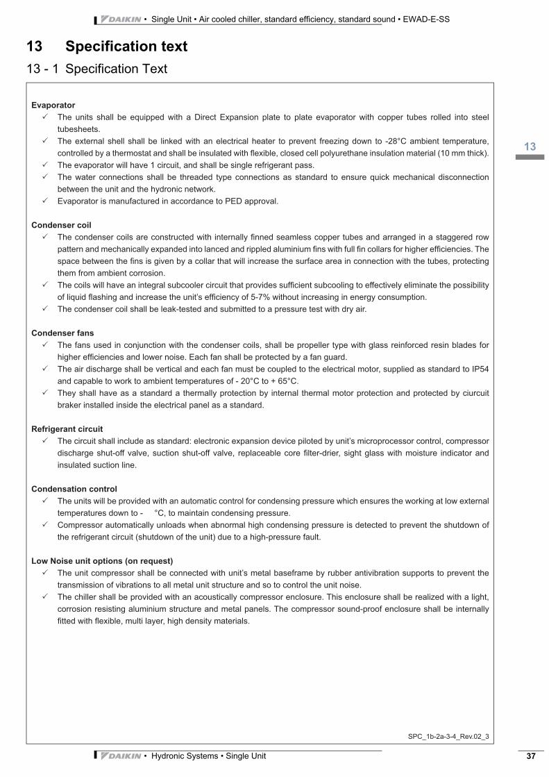
Evaporator
The units shall be equipped with a Direct Expansion plate to plate evaporator with copper tubes rolled into steel
tubesheets.
The external shell shall be linked with an electrical heater to prevent freezing down to -28°C ambient temperature,
controlled by a thermostat and shall be insulated with fl exible, closed cell polyurethane insulation material (10 mm thick).
The evaporator will have 1 circuit, and shall be single refrigerant pass.
The water connections shall be threaded type connections as standard to ensure quick mechanical disconnection
between the unit and the hydronic network.
Evaporator is manufactured in accordance to PED approval.
Condenser coil
The condenser coils are constructed with internally fi nned seamless copper tubes and arranged in a staggered row
pattern and mechanically expanded into lanced and rippled aluminium fi ns with full fi n collars for higher effi ciencies. The
space between the fi ns is given by a collar that will increase the surface area in connection with the tubes, protecting
them from ambient corrosion.
The coils will have an integral subcooler circuit that provides suffi cient subcooling to effectively eliminate the possibility
of liquid fl ashing and increase the unit’s effi ciency of 5-7% without increasing in energy consumption.
The condenser coil shall be leak-tested and submitted to a pressure test with dry air.
Condenser fans
The fans used in conjunction with the condenser coils, shall be propeller type with glass reinforced resin blades for
higher effi ciencies and lower noise. Each fan shall be protected by a fan guard.
The air discharge shall be vertical and each fan must be coupled to the electrical motor, supplied as standard to IP54
and capable to work to ambient temperatures of - 20°C to + 65°C.
They shall have as a standard a thermally protection by internal thermal motor protection and protected by ciurcuit
braker installed inside the electrical panel as a standard.
Refrigerant circuit
The circuit shall include as standard: electronic expansion device piloted by unit’s microprocessor control, compressor
discharge shut-off valve, suction shut-off valve, replaceable core fi lter-drier, sight glass with moisture indicator and
insulated suction line.
Condensation control
The units will be provided with an automatic control for condensing pressure which ensures the working at low external
temperatures down to - °C, to maintain condensing pressure.
Compressor automatically unloads when abnormal high condensing pressure is detected to prevent the shutdown of
the refrigerant circuit (shutdown of the unit) due to a high-pressure fault.
Low Noise unit options (on request)
The unit compressor shall be connected with unit’s metal baseframe by rubber antivibration supports to prevent the
transmission of vibrations to all metal unit structure and so to control the unit noise.
The chiller shall be provided with an acoustically compressor enclosure. This enclosure shall be realized with a light,
corrosion resisting aluminium structure and metal panels. The compressor sound-proof enclosure shall be internally
fi tted with fl exible, multi layer, high density materials.
• Single Unit • Air cooled chiller, standard efficiency, standard sound • EWAD-E-SS
113
• Hydronic Systems • Single Unit38
13 Specification text
13 - 1 Specification Text
SPC_1b-2a-3-4_Rev.02_4
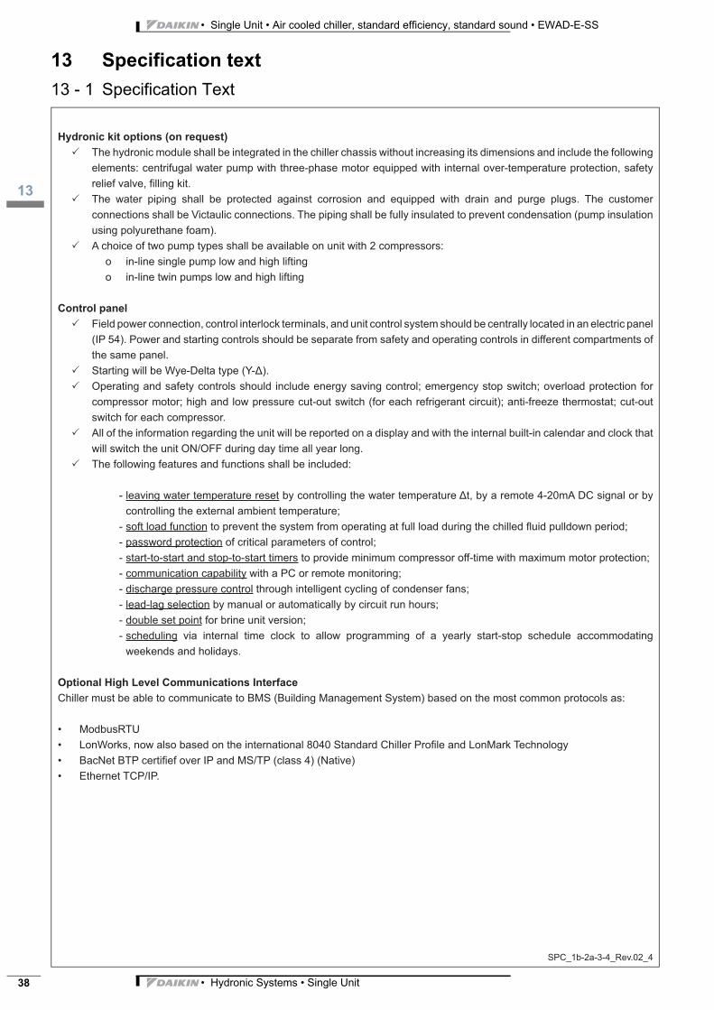
Hydronic kit options (on request)
The hydronic module shall be integrated in the chiller chassis without increasing its dimensions and include the following
elements: centrifugal water pump with three-phase motor equipped with internal over-temperature protection, safety
relief valve, fi lling kit.
The water piping shall be protected against corrosion and equipped with drain and purge plugs. The customer
connections shall be Victaulic connections. The piping shall be fully insulated to prevent condensation (pump insulation
using polyurethane foam).
A choice of two pump types shall be available on unit with 2 compressors:
o in-line single pump low and high lifting
o in-line twin pumps low and high lifting
Control panel
Field power connection, control interlock terminals, and unit control system should be centrally located in an electric panel
(IP 54). Power and starting controls should be separate from safety and operating controls in different compartments of
the same panel.
Starting will be Wye-Delta type (Y- ).
Operating and safety controls should include energy saving control; emergency stop switch; overload protection for
compressor motor; high and low pressure cut-out switch (for each refrigerant circuit); anti-freeze thermostat; cut-out
switch for each compressor.
All of the information regarding the unit will be reported on a display and with the internal built-in calendar and clock that
will switch the unit ON/OFF during day time all year long.
The following features and functions shall be included:
- leaving water temperature reset by controlling the water temperature t, by a remote 4-20mA DC signal or by
controlling the external ambient temperature;
- soft load function to prevent the system from operating at full load during the chilled fl uid pulldown period;
- password protection of critical parameters of control;
- start-to-start and stop-to-start timers to provide minimum compressor off-time with maximum motor protection;
- communication capability with a PC or remote monitoring;
- discharge pressure control through intelligent cycling of condenser fans;
- lead-lag selection by manual or automatically by circuit run hours;
- double set point for brine unit version;
- scheduling via internal time clock to allow programming of a yearly start-stop schedule accommodating
weekends and holidays.
Optional High Level Communications Interface
Chiller must be able to communicate to BMS (Building Management System) based on the most common protocols as:
• ModbusRTU
• LonWorks, now also based on the international 8040 Standard Chiller Profi le and LonMark Technology
• BacNet BTP certifi ef over IP and MS/TP (class 4) (Native)
• Ethernet TCP/IP.

Daikin’s unique position as a manufacturer of airconditioning equipment, compressors and refriger-ants has led to its close involvement in environmen-tal issues. For several years Daikin has had theintention to become a leader in the provision ofproducts that have limited impact on the environ-ment. This challenge demands the eco design anddevelopment of a wide range of products and an en-ergy management system, resulting in energy con-servation and a reduction of waste.
Daikin Europe N.V. participates in the Eu-rovent Certification programme for Air con-ditioners (AC), Liquid Chilling Packages(LCP) and Fan coil units (FCU), Check on-going validity of certificate online: www.eu-rovent-certification.com or using:www.certiflash.com”
EE
DE
N13
-409
•
09/1
2 •
Cop
yrig
ht D
aik
in
Th
e p
rese
nt p
ubl
ica
tion
sup
ers
ede
s E
ED
EN
11-4
09The present leaflet is drawn up by way of information only and does notconstitute an offer binding upon Daikin Europe N.V.. Daikin Europe N.V.has compiled the content of this leaflet to the best of its knowledge. Noexpress or implied warranty is given for the completeness, accuracy, re-liability or fitness for particular purpose of its content and the productsand services presented therein. Specifications are subject to changewithout prior notice. Daikin Europe N.V. explicitly rejects any liability forany direct or indirect damage, in the broadest sense, arising from or re-lated to the use and/or interpretation of this leaflet. All content is copy-righted by Daikin Europe N.V.
BARCODE Daikin products are distributed by:
Naamloze Vennootschap - Zandvoordestraat 300, B-8400 Oostende - Belgium - www.daikin.eu - BE 0412 120 336 - RPR Oostende


