

Applying Misuse Cases to Improve the
Security of Information Systems
John Neil Ruck
Technical Report
RHUL-MA-2009-05
16th February 2009
Royal HollowayUniversity of London
Department of Mathematics
Royal Holloway, University of London
Egham, Surrey TW20 0EX, England
http://www.rhul.ac.uk/mathematics/techreports

1
Title: Title: Title: Title: ApplyingApplyingApplyingApplying Misuse Cases to improve theMisuse Cases to improve theMisuse Cases to improve theMisuse Cases to improve the
SSSSecuriecuriecuriecurity ofty ofty ofty of Information SystemsInformation SystemsInformation SystemsInformation Systems
Name:Name:Name:Name: Ruck, John Neil
Student Number: Student Number: Student Number: Student Number: 100551518
Supervisor: Supervisor: Supervisor: Supervisor: Dr. Geraint Price
Submitted as part of the requirements for the award of the MSc
in Information Security at Royal Holloway, University of London.
I declare that this assignment is all my own work and that I have acknowledged all
quotations from the published or unpublished works of other people. I declare that I have
also read the statements on plagiarism in
Section 1 of the Regulations Governing Examination and Assessment Offences and in
accordance with it I submit this project report as my own work.
Signature:
Date:

2
Table of ContentsTable of ContentsTable of ContentsTable of Contents
Table of Figures .................................................................................................................... 5
Terms and Definitions ........................................................................................................... 7
Executive Summary .............................................................................................................. 8
1 Introduction .................................................................................................................... 9
1.1 The ‘Problem’ .......................................................................................................... 9
1.2 Aim and Objectives ............................................................................................... 10
1.2.1 Aim ................................................................................................................ 10
1.2.2 Preliminary Objectives ................................................................................... 10
1.2.3 Main Objective ............................................................................................... 10
1.3 Structure ............................................................................................................... 11
2 Introduction to Information Systems ............................................................................. 12
2.1 Defining Information Systems ............................................................................... 12
2.2 The Information Systems lifecycle ......................................................................... 12
2.3 Cost of Errors in the System Lifecycle ................................................................... 14
2.4 Requirements for Information Systems ................................................................. 15
2.4.1 Functional Requirements ............................................................................... 16
2.4.2 Non-functional Requirements ......................................................................... 16
2.4.3 Classifying the importance of requirements ................................................... 16
2.5 Summary .............................................................................................................. 17
3 Securing Information Systems ..................................................................................... 18
3.1 Defining Security in Information Systems .............................................................. 18
3.1.1 Defining Information Security ......................................................................... 18
3.1.2 Terms related to Misuses ............................................................................... 19
3.1.3 Terms related to the Prioritisation of Misuses................................................. 19
3.2 Security in the Information Systems ...................................................................... 20
3.2.1 Security Mechanisms ..................................................................................... 20
3.2.2 Security Requirements ................................................................................... 21
3.3 Approaches to identifying security requirements for Information Systems ............. 22
3.3.1 ‘Bottom-up Approach’ to identifying security requirements ............................. 22
3.3.2 A ‘Misuse-driven approach’ to identifying security requirements .................... 23
3.3.3 Approach taken in this Paper ......................................................................... 23
3.4 Summary .............................................................................................................. 23
4 Introducing the Case Study .......................................................................................... 25
4.1 Reason for inclusion ............................................................................................. 25

3
4.2 The Case Study .................................................................................................... 25
5 Introducing Misuse Cases ............................................................................................ 26
5.1 Introduction to Use Cases ..................................................................................... 26
5.1.1 Diagrams ....................................................................................................... 27
5.1.2 Text ............................................................................................................... 28
5.1.3 Using Use Cases ........................................................................................... 30
5.2 Introduction to Misuse Cases ................................................................................ 31
5.2.1 Diagrams ....................................................................................................... 31
5.2.2 Text ............................................................................................................... 32
5.3 Scenarios .............................................................................................................. 33
5.4 Summary .............................................................................................................. 35
6 Using Misuse Cases .................................................................................................... 36
6.1 Technique 1: Misuse Cases to Identify the Top-Level Misuses ............................. 36
6.1.1 Overview ........................................................................................................ 36
6.1.2 Preconditions ................................................................................................. 36
6.1.3 Application ..................................................................................................... 37
6.1.4 Benefits .......................................................................................................... 38
6.1.5 Limitations ..................................................................................................... 39
6.1.6 Striving for Completeness .............................................................................. 40
6.1.7 Extending Technique 1 .................................................................................. 41
6.2 Technique 2: Eliciting Security Requirements with Diagrammatic Misuse Cases .. 43
6.2.1 Overview ........................................................................................................ 43
6.2.2 Striving for Completeness .............................................................................. 44
6.2.3 Pre-conditions ................................................................................................ 45
6.2.4 Application ..................................................................................................... 45
6.2.5 Benefits .......................................................................................................... 47
6.2.6 Limitations ..................................................................................................... 47
6.2.7 Extending Technique 2 .................................................................................. 47
6.3 Technique 3- Eliciting Security Requirements with textual Misuse Cases ............. 49
6.3.1 Overview ........................................................................................................ 49
6.3.2 Striving for Completeness .............................................................................. 49
6.3.3 Pre-conditions ................................................................................................ 50
6.3.4 Application ..................................................................................................... 51
6.3.5 Benefits .......................................................................................................... 54
6.3.6 Limitations ..................................................................................................... 54
6.3.7 Extending Technique 3 .................................................................................. 54

4
6.4 Technique 4- Adapting Misuse Cases to Provide Test Scenarios ......................... 55
6.4.1 Overview ........................................................................................................ 55
6.4.2 Introducing Technique 4 ................................................................................ 55
6.4.3 Pre-conditions ................................................................................................ 59
6.4.4 Potential benefits ........................................................................................... 59
6.4.5 Potential limitations ........................................................................................ 59
6.4.6 Extending Technique 4 .................................................................................. 59
6.5 Summary .............................................................................................................. 60
7 Misuse Cases in Context ............................................................................................. 61
7.1 Increasing importance of Misuse and Use Cases ................................................. 61
7.2 Limitations of Misuse Cases ................................................................................. 61
7.3 Re-use of Misuse Cases ....................................................................................... 62
7.4 Related Work ........................................................................................................ 62
7.5 Summary .............................................................................................................. 63
8 Conclusion ................................................................................................................... 64
8.1 Summary of Findings ............................................................................................ 64
8.2 Relating findings to the original Aim and Objectives .............................................. 65
8.2.1 Aim ................................................................................................................ 65
8.2.2 Preliminary Objectives ................................................................................... 65
8.2.3 Main Objective ............................................................................................... 65
8.3 Further Work from this Dissertation ....................................................................... 67
Bibliography ........................................................................................................................ 68
Appendix A- Use Case for the IT Contractor Management System ..................................... 72
Appendix B- ‘Elevation of Privileges’ Security Use Case ..................................................... 73

5
Table of FiguresTable of FiguresTable of FiguresTable of Figures
Figure 1- The Unified Process ............................................................................................. 13
Figure 2- Cost to repair a requirements error at various development stages of software
systems............................................................................................................................... 15
Figure 3- MoSCoW Method for classification of requirements ............................................. 17
Figure 4- Security Threats, Requirements, and Mechanisms. ............................................. 20
Figure 5- A simple use case diagram for an IT Contractor Management System ................ 27
Figure 6- Functional decomposition of the Pay Invoice use case ........................................ 28
Figure 7- A simple Textual use case for Pay Invoice ........................................................... 29
Figure 8- Sample alternative flow that models a misuse and consequent system behaviour 30
Figure 9- Simple misuse case diagram for the IT Contractor Management System ............ 31
Figure 10- A simple misuse case to demonstrate the include relationship ........................... 32
Figure 11- Rules governing creation of relationships between Use and Misuse Cases ....... 32
Figure 12- Elements used in Activity diagrams in this Paper ............................................... 34
Figure 13- Activity Diagram for an attempt to misuse the system by observing the stored
(payment) amount ............................................................................................................... 35
Figure 14- Output from the application of Technique 1 to the Case Study ........................... 37
Figure 15- STRIDE Chart .................................................................................................... 41
Figure 16- Example Misuses Table capturing the misuses to the IT Contractor Management
System ................................................................................................................................ 42
Figure 17- Interplay of Use and Misuse cases with Functional and Non-Functional
Requirements ..................................................................................................................... 43
Figure 18- List of Possible relationships between misuse cases and sub-system functions
(describing security requirements) ...................................................................................... 44
Figure 19- Eliciting security requirements using diagrammatic misuse cases ...................... 45
Figure 20- ‘Misuse and Requirements’ table for recording misuse and security requirements
information elicited .............................................................................................................. 48
Figure 21- Security Services relating to Data Confidentiality ............................................... 50
Figure 22- Security Use Case for Data Confidentiality of Payment Data (Part 1) ................. 51
Figure 23- Security Use Case for Data Confidentiality of Payment Data (Part 2) ................. 52
Figure 24- Security Use Case for Data Confidentiality of Payment Data (Part 3) ................. 53
Figure 25- Activity Diagram showing the Test Scenario and Test Cases (TCs) for Data
Confidentiality ..................................................................................................................... 56

6
Figure 26- Activity Diagram showing the Test Scenario for the 'Elevation of Privilege misuse
........................................................................................................................................... 58
Figure 27- How the sub-objectives were achieved .............................................................. 66

7
Terms and DefinitionsTerms and DefinitionsTerms and DefinitionsTerms and Definitions
Accountability: The property that ensures that the actions of an entity may be traced uniquely to the entity; [ISO, 2004] Asset: anything that has value to an organisation [ISO, 2005]
Authenticity: The property that ensures that the identity of a subject or resource is the one claimed. Authenticity applies to entities such as users, processes, systems and information; [ISO, 2004] Availability is the property of being accessible and usable upon demand by an authorised entity; [ISO, 1989] Confidentiality is the property that information is not made available or disclosed to unauthorised individuals, entities, or processes; [ISO, 1989]
Integrity is the property of safeguarding the accuracy and completeness of assets; [ISO, 1989] Non-repudiation: The ability to prove an action or event has taken place, so that this event or action cannot be repudiated later; [ISO, 1989] Owner (of an asset): the owner of an asset [CC, 2005]
Reliability: the property of consistent intended behaviour and results; [ISO, 2004] Risk: the potential that a given threat will exploit vulnerabilities of an asset or group of assets and thereby cause harm to the organization. It is measured in terms of a combination of the probability of an event and its consequence. [ISO, 2004]
Security Properties: confidentiality, integrity, availability, non-repudiation, accountability, authenticity and reliability [ISO, 2004] Security Services: Defined in full in [ISO, 1989]. The ‘top-level’ Security Services are: authentication, access control, data confidentiality, data integrity, non-repudiation.
Threat: a potential cause of an incident that may result in harm to a system or organization. Example threats are: Eavesdropping, Information modification, System hacking, etc. [ISO, 2004]
Threat sources: entities that can adversely act on assets. Examples of threat sources are hackers, users, computer processes [CC, 2005]
Vulnerability: a weakness of an asset or group of assets that can be exploited by one or more threats [ISO, 2004]

8
Executive SummaryExecutive SummaryExecutive SummaryExecutive Summary
In the Information Security Profession we are losing the Battle. Today’s Information Systems
are, perversely, more secure than Tomorrow’s. The only way we can reverse this trend is by
securing Information Systems smarter and faster than we do today.
This dissertation explores Information Systems and how they are developed with the aim of
incorporating Security in the early stages of their development; using a technique called
‘Misuse Cases’.
Misuse Cases capture how an Information System can be used in a way that it is not
supposed to, either deliberately (an attack) or accidentally (a mistake). It is true to say that
Information Systems are misused by Human beings. Humans may use machines as a proxy
from which to commit their misuses, but ultimately the security profession is at the mercy of
human creativity (and stupidity).
Misuse Cases provide us with a way to reason about how a System might be misused at an
early stage in its development. We can use this information to incorporate countermeasures
into the System’s Requirements (in the form of security requirements).
We apply Four Techniques based on Misuse Cases to a hypothetical Case Study-an IT
Contractor Management System to achieve the following:
• Identify potential top-level Misuses;
• Use Misuse Cases to Elicit Security Requirements;
• Propose a way to develop Tests to verify that Security Requirements have been met.
In applying the Techniques we recognise their benefits and limitations and where
appropriate propose some enhancements.

9
1111 Introduction Introduction Introduction Introduction
This Section provides the background for the dissertation and sets out its Aim, Objectives
and Structure.
1.11.11.11.1 The ‘Problem’The ‘Problem’The ‘Problem’The ‘Problem’
In the early days of Information Systems in the 1970s things were much simpler for Security
Professionals than they are today. The ‘Information System’ was comprised of small number
of mainframe computers connected together. The computers themselves and the people
operating them could be trusted (rightly or wrongly) and the main security problem was how
to communicate securely between the mainframes.
In recent times the number of Information Systems has exploded to the point where they are
pervasive in our everyday lives. McGraw [McGraw, 2006] identifies three trends in
Information Systems that he describes as the ‘Trinity of Trouble’:
Connectivity: The growing connectivity of computers through the Internet has
increased both the number of attack vectors (ways in which attacks can be made)
and the ease with which an attack can be made. [McGraw, 2006]
Extensibility: Systems accept updates or extensions, sometimes referred to as
mobile code so that the functionality of the system can be evolved in an incremental
fashion. [McGraw & Felten, 1999]
Complexity: The unbridled growth in the size and complexity of modern information
systems. [McGraw, 2006]
These three trends combine to provide a significant ‘Problem’ for today’s Security
Professionals; in fact Schneier [Schneier, 2004] argues that today’s computers and networks
are less secure than they were earlier and they will be even less secure in the future.
The ‘Security Battle’ is being lost and to stand a chance of reversing these fortunes the
Security Profession needs to focus on securing information systems faster and smarter.
Software engineers recognised over 15 years ago [Davis, 1993] that it is much cheaper to
identify and fix errors as early on in the development of software as possible. But for some
reason Security Professionals are only just waking up to the need to incorporate security into
Information Systems right from the start.

10
Anecdotal evidence from Information Security Industry shows that, traditionally, Security
Professionals are drawn to technical details. Preferring to focus on tangible components
such as the network architecture of the Information Systems; but in doing so forgetting about
incorporating security into the Information System before the point where the network is
designed.
Requirements are one of the first artefacts produced for an Information System; hence they
seem a logical starting point in a Quest to make security faster and smarter; by considering it
earlier on in the development of Information Systems.
1.21.21.21.2 Aim and ObjectivesAim and ObjectivesAim and ObjectivesAim and Objectives
1.2.11.2.11.2.11.2.1 AimAimAimAim
The Aim of this dissertation is to explore how security can be incorporated in the early
stages of the development of Information Systems using a technique called ‘Misuse Cases’.
The Objectives identified to achieve this aim have been split into Preliminary Objectives and
the Main Objective.
1.2.21.2.21.2.21.2.2 PreliminaryPreliminaryPreliminaryPreliminary ObjectivesObjectivesObjectivesObjectives
The Preliminary objectives enable the Main Objective to be achieved by providing the
background and an overview of the techniques and approach to be used. They are as
follows:
• Introduce Information Systems and their development lifecycle;
• Introduce Security in Information Systems;
• Introduce the Case Study used in achieving the Main Objective;
• Introduce the fundamentals of the techniques that will be applied as part of the Main
Objective.
1.2.31.2.31.2.31.2.3 Main ObjectiveMain ObjectiveMain ObjectiveMain Objective
The Main Objective is to:
“Apply Techniques derived from Misuse Cases using a Case Study to understand how they
can ‘add value’ when securing of Information Systems”

11
This is enabled by four Sub-objectives namely:
• Using Misuse Cases to Identify potential top-level Misuses of an Information System;
• Using Misuse Cases to Elicit Security Requirements for an Information System;
• Proposing a technique to develop Tests to verify that Security Requirements have
been met;
• Considering Misuse Cases in the context of the ‘wider picture’.
1.31.31.31.3 StructureStructureStructureStructure
This dissertation will take the following structure:
• Section 2 provides an introduction to Information Systems and their development
lifecycle, focussing on the earlier aspects of the lifecycle
• Section 3 provides an introduction to Security in Information Systems, focussing on
how the property of Security can be incorporated early on in the lifecycle.
• Section 4 outlines the Case Study that is used throughout the Paper to demonstrate
the Misuse Case Techniques
• Section 5 introduces the fundamentals of the techniques that will be applied in
Section 6. Namely: use cases, misuses cases and scenarios.
• Section 6 applies Four Techniques derived from Misuse Cases to the Case Study to
understand how they can be used to improve the Security of Information Systems.
• Section 7 considers the Misuse Case Techniques in the context of the ‘wider picture’
of Information Security.
• Section 8 summarises the findings of the dissertation and considers to what extent
original aim and objectives were met, and includes a discussion of potential further
work leading on from this dissertation.

12
2222 Introduction toIntroduction toIntroduction toIntroduction to Information SystemsInformation SystemsInformation SystemsInformation Systems
In this Section we provide an introduction to Information Systems and their development
lifecycle. We introduce the theory behind requirements for Information Systems to provide a
basis for understanding security requirements in later Sections.
2.12.12.12.1 DefiningDefiningDefiningDefining Information SystemsInformation SystemsInformation SystemsInformation Systems
There are a wide range of definitions for Information Systems, the one chosen by this Paper
is from the US Department of the Interior [Tipton, 2004]:
“Information system means a discrete set of information technology (IT), data, and
related resources, such as personnel, hardware, software, and associated IT
services organized for the collection, processing, maintenance, use, sharing,
dissemination, or disposition of information.”
This definition enables one to consider an Information System as a discrete entity; one that
has its own lifecycle and attributes unique to that Information System, such as security
requirements.
2.22.22.22.2 The The The The Information Systems lifecycleInformation Systems lifecycleInformation Systems lifecycleInformation Systems lifecycle
Information Systems do not just happen, as with all systems, they start as a concept and are
developed into an operational system. A system lifecycle is the process of developing an
Information system and it can be modelled using a system development process. There are
a range of system development processes available, the one chosen for this paper is the
Unified Process (UP); because many other development lifecycles are derived from it and
the UP has no intellectual property issues associated with it. The UP is described in detail in
[Jacobson, Booch, & Rumbaugh, 1999].

13
Figure 1- The Unified Process described in [Jacobson, Booch, & Rumbaugh, 1999] electronic copy from
[Kivistö, 2000]
The phases of the system lifecycle are shown in the columns of Figure 1; the system starts
in the ‘Inception’ phase and ends in ‘Transition’ phase. The process is Iterative and
Incremental which has the benefit of recognising the fact that requirements are not fully
defined up front and typically need to be refined in successive iterations [Jacobson, Booch,
& Rumbaugh, 1999, Chapter 1].
The rows of Figure 1 describe the core workflows (referred to as workflows from here on in)
that are being followed throughout the lifecycle and the shapes show the amount of effort
expended on each workflow in relation to the phase in the system lifecycle. The thicker the
shape the more of the workflow is done at that point in the lifecycle; for example the UP
recommends that the majority of the Requirements workflow is done during the Elaboration
phase.
The focus of this Paper is on the workflows that are applied during the development of an
Information System. The workflows of the Unified Process are where the work is done; the
phases refer to moments in time. The Techniques discussed in this Paper are applied by
workflow activities; hence this Paper focuses on describing the techniques in relation to the
workflows, rather than phases.
1
2
3

14
The Misuse Case techniques applied by Paper relate to one or more of the workflows
numbered on Figure 1, discussed in turn:
1) ‘Requirements’ is the first workflow. Its principal output is set of requirements that are
not necessarily consistent or comprehensive and there may be repetition;
2) ‘Analysis’ is the second workflow where the requirements are refined and structured
to achieve a more precise understanding and a set of requirements that is easier to
maintain [Jacobson, Booch, & Rumbaugh, 1999, Chapter 8];
3) ‘Testing’ is a workflow which is done through the lifecycle of the Information System,
as shown by the shape in Figure 1.
A great benefit of the Unified Process is that it ensures that all of the System’s requirements
are realised by the subsequent workflows [Jacobson, Booch, & Rumbaugh, 1999, Chapter
2]. This is sometimes called ‘Traceability of Requirements’.
It should be noted that the Unified Process only models the Information System’s lifetime to
the point where it ‘Transitions’ to operations. It is recognised that when applying security
techniques, other than the ones discussed in this Paper, it is important to consider the
‘Maintenance’ and ‘Decommission’ Phases of the Information System and NIST Special
Publication 800-64 [Grance, Hash, & Stevens, 2004] is recommended as a further reference
for this purpose.
2.32.32.32.3 Cost Cost Cost Cost of of of of EEEErrors in the rrors in the rrors in the rrors in the System LifecySystem LifecySystem LifecySystem Lifecycccclelelele
The Unified Process was developed by Jacobson et al [Jacobson, Booch, & Rumbaugh,
1999] to address the fact that a lot of effort was being wasted by computer programmers
developing code that did not meet the requirements for the System.
Within the software engineering community it is an accepted tenet that resolving errors
earlier in the lifecycle is much cheaper than later on. In terms of security ‘fixing an error’ is
equivalent to mitigating a security problem.
15
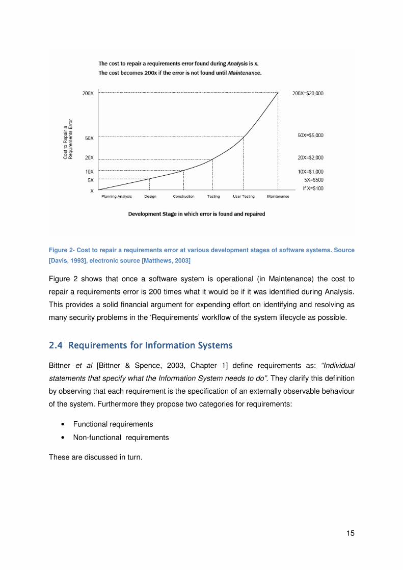
Figure 2- Cost to repair a requirements error at various development stages of software systems. Source
[Davis, 1993], electronic source [Matthews, 2003]
Figure 2 shows that once a software system is operational (in Maintenance) the cost to
repair a requirements error is 200 times what it would be if it was identified during Analysis.
This provides a solid financial argument for expending effort on identifying and resolving as
many security problems in the ‘Requirements’ workflow of the system lifecycle as possible.
2.42.42.42.4 Requirements for Information SystemsRequirements for Information SystemsRequirements for Information SystemsRequirements for Information Systems
Bittner et al [Bittner & Spence, 2003, Chapter 1] define requirements as: “Individual
statements that specify what the Information System needs to do”. They clarify this definition
by observing that each requirement is the specification of an externally observable behaviour
of the system. Furthermore they propose two categories for requirements:
• Functional requirements
• Non-functional requirements
These are discussed in turn.

16
2.4.12.4.12.4.12.4.1 Functional RequirementFunctional RequirementFunctional RequirementFunctional Requirementssss
Bittner et al [Bittner & Spence, 2003, Chapter 1] explain functional requirements as
specifying the input and output behaviour of a system, i.e. the functions that it will provide.
Use cases (discussed in more detail in Section 5.1) are the principal way of describing
functional requirements and essentially describe how users (actors) will interact with the
System via the functions it provides
An example functional (security) requirement is: “The System must protect the confidentiality
of payment data“.
2.4.22.4.22.4.22.4.2 NonNonNonNon----functional Requirementsfunctional Requirementsfunctional Requirementsfunctional Requirements
Bittner et al [Bittner & Spence, 2003, Chapter 1] explain non-functional requirements (NFRs)
as requirements specifying the qualities a system needs, such as availability, reliability,
performance and supportability of the system. They propose the use of a document called
the Supplementary Specifications to store NFRs.
Any requirements that do not describe functions of the Information System are classed as
NFRs; so any requirements that describe what a System must not do are classed as NFRs.
An example of this can be seen in Section 6.3.4.1.
An example non-functional (security) requirement is: ”The System must have prevented the
Misuser from viewing the payment data”.
2.4.32.4.32.4.32.4.3 Classifying the importance of requirementsClassifying the importance of requirementsClassifying the importance of requirementsClassifying the importance of requirements
Requirements (irrespective of whether they are functional or non-functional) are not all
mandatory, for example a requirement may be just desirable. In order to distinguish between
different types for requirements the MoSCoW Method [Clegg & Barker, 1994] is commonly
used, this is described in detail in Figure 3.

17
Key word Definition
Must Mandatory requirements. If a single ‘must’ requirement is not
implemented the System is considered as a failure.
Should Desirable requirements. Whilst not critical to the success of the
System they should be implemented if at all possible
Could Nice to have requirements, if they are easy to achieve then
implement them otherwise they can be ignored.
Won’t have
(this time)
Not considered as important enough for inclusion in the
requirements set but are recorded for potential future use.
Figure 3- MoSCoW Method for classification of requirements
Obviously, implementing against requirements that are not required wastes money; applying
the MoSCoW Method correctly (during the ‘Requirements’ and ‘Analysis’ workflows) will help
to ensure that the set of requirements is minimum and necessary; that is requirements that
are not relevant to the system will either be eliminated or classified as ‘Wont have (this
time)’.
2.52.52.52.5 SummarySummarySummarySummary
In this Section we have introduced Information Systems and their aspects that are important
for this Paper. The Unified Process has been chosen as the model for the system
development process and the concept of workflows will be used throughout the Paper to put
the techniques discussed in this Paper in the context of the system development lifecycle.
We have discussed the financial imperative of getting the Requirements right and a
distinction has been made between functional and non-functional requirements. Finally we
presented the MoSCoW method as a way of classifying requirements.

18
3333 Securing Information SystemsSecuring Information SystemsSecuring Information SystemsSecuring Information Systems
In this Section we build on the information provided in the previous section to explain the
aspects of securing Information Systems relevant to this Paper. We start by defining the
terms that will be used throughout the remainder of the Paper then explain security in the
context of the systems lifecycle workflows and conclude with a discussion of the different
approaches to identifying security requirements for Information Systems.
3.13.13.13.1 Defining Security in Information SystemsDefining Security in Information SystemsDefining Security in Information SystemsDefining Security in Information Systems
This Paper recognises that there are a variety of different definitions within the information
security arena1. This Section defines the significant terms used throughout the Paper;
related terms are defined in the ‘Terms Used’ Section. Red text is used to distinguish any
definition or modification proposed by this Paper.
3.1.13.1.13.1.13.1.1 Defining Information SecurityDefining Information SecurityDefining Information SecurityDefining Information Security
ISO13335-1 [ISO, 2004] defines Information Security as:
Information Security: all aspects related to defining, achieving and maintaining
confidentiality, integrity, availability, non-repudiation, accountability, authenticity
and reliability, of information or information processing facilities; [ISO, 2004]
This definition is useful because Information Security in specified in terms of the ‘Security
Properties’ defined in ISO13335-1 (detailed in full in the ‘Terms Used’ Section of this Paper).
This Paper favours the terms defined in ISO13335-1; but also recognises that the Security
Services defined in ISO7498-2 [ISO, 1989] are closely related to the Security Properties
defined in ISO13335-1. Indeed ISO7498-2 provides a more specific consideration of the
individual Security Services than ISO13335-1 does for the individual Security Properties.
Hence in Section 6.3.2 of this Paper we suggest that the extra information in ISO7498-2 is
referred to.
1 Incidentally, (Mayer, Patrick, & Matulevičius, 2007) draws the various terms together and attempts to
provide some clarity

19
3.1.23.1.23.1.23.1.2 TTTTerms related to Misuseserms related to Misuseserms related to Misuseserms related to Misuses
This Paper proposes the following definition:
Misuse: describes a potential use of a system by a Threat source such that an
asset’s security properties are compromised. Misuses may be accidental or
deliberate.
The ‘Misuse’ definition recognises that misuses can be either deliberate or accidental so the
following definitions are proposed.
Attack: A Misuse that is intentional and malicious
Mistake: A Misuse that is accidental
The following definitions will be used when describing misuses and countering them.
Countermeasure: Similar to Control but, includes security objectives and security
requirements [CC, 2005]
Control: a practice, procedure or mechanism that treats risks [ISO, 2004] and
misuses.
The noun ‘Countermeasure’ is used as a generic term to refer to a method that is used ‘to
counter’ (the verb) a misuse.
3.1.33.1.33.1.33.1.3 TTTTerms related to the Prioritisation of Misuseserms related to the Prioritisation of Misuseserms related to the Prioritisation of Misuseserms related to the Prioritisation of Misuses
The following definitions will be used when considering how misuses can be prioritised, the
original definitions have been slightly modified to refer to misuses (rather than attacks), and
this is denoted by the use of red text:
Impact: the result of an information security incident. [ISO, 2004]. I.e. the
consequence of a misuse being realised.
Likelihood: A measure of the probability of a misuse being successfully realised (i.e.
an asset being compromised) [CESG, 2007]
Motivation: The measured desire to mount a misuse. It is dependent on ideals such
as ideology coercion, disaffection. [CESG, 2007]
Capability: The measured ability to mount misuses [CESG, 2007]

20
3.23.23.23.2 Security in the Security in the Security in the Security in the IIIInformation Systemnformation Systemnformation Systemnformation Systemssss
There are a number of aspects to security in the information system, Figure 4 summarises
these aspects:
Figure 4- Security Threats, Requirements, and Mechanisms. Source [Firesmith, 2003]
Figure 4 shows the interaction between Security Threats (which are referred to as Misuses
by this Paper), Security Requirements and Security Mechanisms. It illustrates that there is a
clear distinction to be made between the Security Requirements and Mechanisms, the
former requiring the latter. The two aspects will now be discussed separately:
3.2.13.2.13.2.13.2.1 Security MechanismsSecurity MechanismsSecurity MechanismsSecurity Mechanisms
As defined in ISO7498-2 [ISO, 1989] Security mechanisms implement the ‘Security Services’
(note: this Paper uses the term ‘Security Properties’ in favour of Security Services). Some
example security mechanisms are: Encipherment, digital signature, authentication exchange
and notarization.
ISO7498-2 states that in general security mechanisms belong to one of three (overlapping)
classes:
1) Prevention (of the event)
2) Detection (of the event)
3) Recovery (from the event). Sometimes referred to as Response
In Section 3.2.2 we consider how these classes can also be applied to security
requirements.
3.2.1.13.2.1.13.2.1.13.2.1.1 Security Mechanisms in the System LifecycleSecurity Mechanisms in the System LifecycleSecurity Mechanisms in the System LifecycleSecurity Mechanisms in the System Lifecycle
As Firesmith [Firesmith, 2003] points out Security Mechanisms constrain the design of an
Information System. We expand in this point to cast it in the context of the system lifecycle
and interpret it to mean that security mechanisms are relevant in the ‘Design’ and
‘Implementation’ workflows in the System lifecycle; because they implement security
properties.

21
3.2.23.2.23.2.23.2.2 Security RequirementsSecurity RequirementsSecurity RequirementsSecurity Requirements
Security requirements are addressed in ISO13335-1 [ISO, 2004, p18] as:
“IT security requirements: "ICT security requirements, e.g., in terms of
confidentiality, integrity, availability, non-repudiation, accountability, authenticity
and reliability, particularly with regard to the views of the asset owners…"
In other words security requirements should be written in terms of the Security Properties.
Two example requirements are given below:
1) “The System must protect the integrity of the payment data”
2) “The System must digitally sign the payment data”
The first requirement specifies the security property of integrity; it is an example of a good
security requirement because it specifies ‘what’ is required but does not constrain the
solution.
The second requirement specifies the security mechanism of a digital signature. Firesmith
[Firesmith, 2003] makes it clear that security requirements should not be specified in terms
of security mechanisms. In this example we can see why. Because the requirement
mandates that a digital signature must be used; another mechanism, which may be more
appropriate, such as a Message Authentication Code (MAC) could not be implemented
instead. The requirement has constrained the solution; it should have specified ‘what’ not
‘how’.
This Paper recognises the three classes of security mechanism discussed in Section 3.2.1
and note that definition of ‘IT Security Requirements’ does not incorporate the concept of
Recovery from (or Response to) a security incident.
An example of a requirement for a system to respond is: “The System must notify the
administrator if nefarious behaviour is detected”.
By considering just the security properties such a requirement may have been missed.
Hence this Paper recommends when identifying security requirements that each of the
classifications (prevention, detection and response) is considered in turn so that important
requirements are not overlooked.

22
3.2.2.13.2.2.13.2.2.13.2.2.1 Security RequiremeSecurity RequiremeSecurity RequiremeSecurity Requirements in the System Lifecyclents in the System Lifecyclents in the System Lifecyclents in the System Lifecycle
Security Requirements are no different from other system requirements and as such are
identified during the ‘Requirements’ workflow and refined during the ‘Analysis’ workflow.
They provide the first opportunity to incorporate security into the Information System. This is
because the Requirements are the first principal artefact produced by Unified Process; for
further information refer to [Jacobson, Booch, & Rumbaugh, 1999, Chapter 2].
3.33.33.33.3 Approaches to Approaches to Approaches to Approaches to identifying security requireidentifying security requireidentifying security requireidentifying security requirements forments forments forments for Information Information Information Information
SystemsSystemsSystemsSystems
Identifying and maintaining security requirements is complex undertaking [McGraw, 2006].
This sub-section discusses two diverse approaches to identifying security requirements for
Information systems and explains how this Paper strives to combine these approaches.
3.3.13.3.13.3.13.3.1 ‘‘‘‘BottomBottomBottomBottom----up Approachup Approachup Approachup Approach’’’’ to identifying security requirementsto identifying security requirementsto identifying security requirementsto identifying security requirements
The ‘Bottom-up Approach’ is defined by Sindre et al [Sindre, Firesmith, & Opdhal, 2003] in
the context of identifying threats. The approach is based on starting with a comprehensive
list (what this Paper terms: the ‘Foundation Set’) and selecting the elements on that list that
are relevant to the system. This sub-section discusses how the Common Criteria2 [CC,
2005] encourages a Bottom-up approach to identifying security requirements.
Common Criteria Part 2 details a comprehensive Foundation Set of Security Functional
Requirements (SFRs). It is an International Standard so one could legitimately expect that a
high proportion of the relevant security requirements are represented; due to the level of
involvement from International Experts. Having such a comprehensive Foundation Set of
security requirements is the greatest strength of standards like the Common Criteria
because by considering all of the requirements in the Foundation Set one can have
reasonable confidence that important security requirements have not been forgotten.
The greatest weakness of the bottom-up approach is that, as is the case of Common
Criteria, no specific guidance is provided on how to select the requirements that are
important for a specific Information System. It is assumed that evaluators (and developers)
of the System will be able to consider each SFR and use their judgement to decide which
requirements apply to the individual System [Boswell & Hill, 2006, p7]. Making such an
2 The Common Criteria is intended to be a Security Evaluation standard; however it contains a
comprehensive list of security requirements that can be used by Developers of information systems irrespective of whether a Common Criteria evaluation is intended for the System.

23
assumption might be reasonable when the developers have experience of applying the
Common Criteria but in the situation where they do not, how can they be expected judge
which requirements are relevant and which ones are not? To answer that question we
consider the ‘Misuse-driven approach’.
3.3.23.3.23.3.23.3.2 A ‘A ‘A ‘A ‘MisuseMisuseMisuseMisuse----drivendrivendrivendriven aaaapproachpproachpproachpproach’’’’ to identifying security requirementsto identifying security requirementsto identifying security requirementsto identifying security requirements
The ‘Misuse-driven Approach’ is predicated on first identifying the potential misuses of a
system and then deriving security requirements to counter those specific misuses. Figure 4
shows an example of the Misuse-driven Approach, albeit using different terminology,
‘Security Threats’ (or Misuses) necessitate Security Requirements (to counter the misuses).
Applying the ‘Misuse-driven Approach’ means that each of the System’s security
requirements is justified by the misuse it counters. This is in contrast to Common Criteria’s
Bottom-up approach, which (as discussed in Section 3.3.1) provides no guidance on
selection (let alone justification) of security requirements.
The greatest weakness of applying the Misuse-driven approach is that it is not a ‘complete’
technique. Because there is no Foundation Set; there is no guarantee that it will identify all of
misuses of a system or indeed all of the security requirements necessary to counter the
misuses it does identify.
3.3.33.3.33.3.33.3.3 Approach taken in this PaperApproach taken in this PaperApproach taken in this PaperApproach taken in this Paper
The Techniques applied in Section 6 are predicated on the Misuse-driven Approach so
inherit the weakness of not being ‘complete’. For each of the Techniques (1, 2 and 3) we
consider how we can increase the ‘coverage’ of the Technique to make it is complete as
possible. In order to do this a sub-section is added for each Technique entitled ‘Striving for
completeness’ where we consider how pre-existing ‘Foundation Sets’ can be incorporated
into the techniques, (for example the detailed list of Security Services in [ISO, 1989]).
3.43.43.43.4 SummarySummarySummarySummary
In this Section we have defined the security-related terms that will be used in the remainder
of this dissertation and explained the important distinction between security requirements
which should not constrain the solution and security mechanisms that are needed to
implement the security properties described in the security requirements.

24
We proposed that security requirements to ‘Respond’ to misuses are considered in addition
to security requirements to achieve the security properties.
We discussed two different approaches to identifying security requirements for Information
Systems and propose a way that the ‘Misuse-driven approach’ followed by this dissertation
can be enhanced by incorporating the ‘Foundation Sets’ from the ‘Bottom-up Approaches’.
With the ultimate aim of making the Misuse-driven approach as complete as possible.
25
4444 Introducing the Case StudyIntroducing the Case StudyIntroducing the Case StudyIntroducing the Case Study
This is a short section to introduce the Case Study- An IT Contractor Management System.
4.14.14.14.1 Reason for inclusionReason for inclusionReason for inclusionReason for inclusion
The Case Study is a hypothetical example that has been included as a vehicle to
demonstrate the application of the techniques throughout this Paper.
4.24.24.24.2 The Case StudyThe Case StudyThe Case StudyThe Case Study
The IT Contractor Management System is an Information System that is owned and
managed by a Company (WCS Services) whose business is sub-contracting Information
Technology (IT) Contractors to large multinational companies. Human Resource (HR)
Administrators are employed by WCS Services to manage the work and payment of the IT
Contractors.
The System provides the following functions:
• IT Contractors and HR Administrators can ‘Arrange a Job’
• IT Contractors can ‘Submit Invoices’
• IT Contractors can ‘Change (their) Payment Details’
• HR Administrators can ‘Pay Invoices’
The System is connected to the Internet and provides a web-based interface to IT
Contractors who will use it to access the functions of the System over the Internet. It is
possible for IT Contractors to write data to the System, this is necessary in order to enable
them to upload their Invoices and change their payment details.
26
5555 Introducing Introducing Introducing Introducing Misuse CasesMisuse CasesMisuse CasesMisuse Cases
Misuses Cases are defined by Alexander [Alexander I. F., 2003] as: “(Simply) A Use Case
from the point of view of an Actor hostile3 to the system under design.” As this definition
suggests use cases are the starting point for misuses cases, as will become apparent during
this Paper.
In this Section we introduce three techniques that provide the foundations for the
Techniques we apply in Section 6:
• Use cases;
• Misuse cases;
• Scenarios, which use a modelling technique known as Activity Diagrams to combine
the information use and misuse cases.
5.15.15.15.1 Introduction to Use CasesIntroduction to Use CasesIntroduction to Use CasesIntroduction to Use Cases
Use cases are a modelling technique that originated in software engineering, initially
proposed by Jacobson in an article as long ago as 1987 [Jacobson, 1987]. Since then they
have been developed into a mature technique that is used in a wide range of applications. In
this Paper we follow the recommendation of Jacobson et al [Jacobson, Ericsson, &
Jacobson, 1995, Chapter 9] and apply use cases in the development of Information
Systems.
Use cases are a very powerful requirements modelling technique because they provide a
standard way of capturing, exploring and documenting what a system should do (i.e. its
functional requirements) [Bittner & Spence, 2003, Chapter 1].
As discussed in Section 2.4.2, use cases (describing functional requirements) do not exist in
isolation they are complemented by the Supplementary specification (describing non-
functional requirements).
Use cases can be expressed in two forms: diagrams or text, these are discussed below.
3 ‘Hostile’ does not necessarily imply a deliberate attack on the System’s design, it could also be
taken to mean an accidental undermining of the System’s design by a mistake.

27
5.1.15.1.15.1.15.1.1 DiagramsDiagramsDiagramsDiagrams
Use case diagrams have the advantage that they are visual representations of the use case,
but have the corresponding disadvantage that they only contain a top-level description of the
use case and leave the detail to textual use cases. Figure 5 illustrates a simple example of a
use case diagram for the IT Contractor Management System. Note it is not the complete use
case, refer to Appendix A for the complete use case.
Figure 5- A simple use case diagram for an IT Contractor Management System
The IT Contractor and HR Administrator shown in Figure 5 are Actors. Bittner et al [Bittner &
Spence, 2003] define an actor as a role that a user can play when interacting with the
System. A user can either be an individual or another system. In this example the Actor is an
individual.
‘Submit Invoice’ and ‘Pay Invoice’ shown in Figure 5 are Use Cases. Bittner et al [Bittner &
Spence, 2003] define use cases as describing how an actor uses a system to achieve a goal
and what the system does for the actor to achieve that goal (i.e. the ‘value’ a system
provides to the user).
The line between IT Contractor and ‘Submit Invoice’ represents that they communicate. The
arrow shows that the IT Contractor initiates the communication.
The IT Contractor Management System is represented by the box which shows its System
Boundary; anything inside the box is internal to the System, anything outside the box is
external to the System. Use Cases are within the System Boundary because they describe
the functional requirements of the System and Actors are outside the System Boundary
because they interact with the System but are not part of it.

28
5.1.1.15.1.1.15.1.1.15.1.1.1 Functional DecompositionFunctional DecompositionFunctional DecompositionFunctional Decomposition
Functional decomposition is a technique that can be applied to use cases (and misuse
cases) and is described in more detail in [Pauli & Xu, 2006]. By applying this technique to
use case diagrams the activities that make up a use case can be represented separately.
Figure 6- Functional decomposition of the Pay Invoice use case
The <<include>> relationship is used to show that the ‘Pay Invoice’ use case includes the
other four uses cases shown in Figure 6.
Bittner et al [Bittner & Spence, 2003, Chapter 5] recommend against the use of functional
decomposition on diagrammatic use cases because it is frequently used incorrectly and they
recommend that textual use cases are used instead to decompose use cases. In some
cases however, textual use cases are not be available.
Technique 2 demonstrated in Section 6.2; uses functional decomposition on diagrammatic
use cases (with caution) because doing so enables a more in-depth analysis when starting
with use case diagrams only.
5.1.25.1.25.1.25.1.2 TextTextTextText
Whilst use case diagrams are good for providing an easily accessible, top-level
representation of the system’s functionality; experts argue that use cases are primarily a text
form [Cockburn, 2001]. Textual descriptions are used to elaborate each use case and
contain much more detail than it is possible to capture in the diagrams.

29
Use Case Name: Pay Invoice
Brief description: This Use Case describes how an HR Administrator pays an invoice
Basic Flow:
1. The use case begins when the HR Administrator logs on to the System providing their
authentication credentials
{log in}
2. The System presents the HR Administrator with the range of services available to the HR
Administrator
3. The HR Administrator selects the ‘Pay Invoice’ service
4. The System presents the HR Administrator with a set of Invoices which have been submitted
but not processed.
5. The HR Administrator selects an Invoice and Approves it
{approve invoice}
6. The System displays to the HR Administrator the amount to be paid to the IT Contractor.
7. The HR Administrator authorises the payment amount
{authorise payment}
8. The System makes the Payment to the IT Contractor
{make payment}
9. Use case ends
Preconditions:
• The HR Administrator must have some means of authenticating to the System (authentication
credentials)
• At least one IT Contractor must have submitted a new Invoice
Post conditions:
• The HR Administrator logs off the System
Figure 7- A simple Textual use case for Pay Invoice
Figure 7 shows a simple textual use case for ‘Pay Invoice’. The Basic flow is used to
describe the interactions between the Actor (the HR Administrator) and the System. The
preconditions are things that must all be true before the use case starts and the post
conditions are things that may be true once the use case ends. The bold text in braces are
called extension points these are markers in the basic flow that can be referred to from other
use cases, see Figure 8 for an example.
30
5.1.2.15.1.2.15.1.2.15.1.2.1 Alternative FlowsAlternative FlowsAlternative FlowsAlternative Flows
Alternative flows are ‘sub-routines’ that are not described in the Basic flows of the use case.
They are used to describe how the System handles things like error conditions and other
behaviour that is not part of the basic flow [Bittner & Spence, 2003, Chapter 9].
Alternative flows can also be used to describe security requirements (how the system
behaves during a misuse) [Ivar Jacobson Consulting, 2005].
At {authorise payment}
1. Misuser attempts to observe the payment data stored on the System
2. The System has protected the confidentiality of the payment data so the Misuser is unable to
view the payment data
3. System logs the activity (attempted access to the payment data)
The use case resumes the basic flow at {authorise payment}
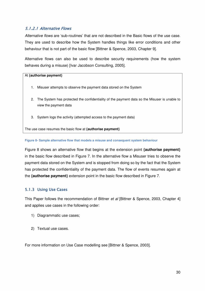
Figure 8- Sample alternative flow that models a misuse and consequent system behaviour
Figure 8 shows an alternative flow that begins at the extension point {authorise payment}
in the basic flow described in Figure 7. In the alternative flow a Misuser tries to observe the
payment data stored on the System and is stopped from doing so by the fact that the System
has protected the confidentiality of the payment data. The flow of events resumes again at
the {authorise payment} extension point in the basic flow described in Figure 7.
5.1.35.1.35.1.35.1.3 Using UsUsing UsUsing UsUsing Use Casese Casese Casese Cases
This Paper follows the recommendation of Bittner et al [Bittner & Spence, 2003, Chapter 4]
and applies use cases in the following order:
1) Diagrammatic use cases;
2) Textual use cases.
For more information on Use Case modelling see [Bittner & Spence, 2003].

31
5.25.25.25.2 Introduction to Misuse CasesIntroduction to Misuse CasesIntroduction to Misuse CasesIntroduction to Misuse Cases
The forerunner to Misuse Cases, Abuse cases were proposed by McDermott et al
[McDermott & Fox, 1999] as an adaptation to use cases to aid in the identification of security
requirements. To all intents and purposes they are the same technique by a different name.
Sindre et al [Sindre & Opdahl, 2001] were the first to propose the term ‘Misuses Cases’ and
described them as a conceptual extension of use cases, describing actions that should not
be possible in a system. They proposed both diagrammatic and textual forms for misuse
cases.
5.2.15.2.15.2.15.2.1 DiagramsDiagramsDiagramsDiagrams
The original concept proposed by Sindre et al [Sindre & Opdahl, 2001] of misuse case
diagrams was adapted slightly by Alexander [Alexander I. F., 2003]; by introducing some
new relationships between the misuse cases and use cases (threaten and mitigate), these
new relationships are used in Figure 9 below.
Figure 9- Simple misuse case diagram for the IT Contractor Management System
In Figure 9 the misuse case ‘View Payment’ (in black) threatens use case ‘Pay Invoice’ (in
white) and a new use case of ‘Protect Confidentiality’ has been added to mitigate the ‘View
Payment’ misuse.
The <<threaten>> and <<mitigate>> relationships proposed by Alexander [Alexander I. F.,
2003] are used throughout this Paper to describe the relationship between use case and
misuse cases. Note that the line is solid rather than dashed for misuse case and use case
relationships; this is just because Alexander proposed a solid line to represent the
relationship and we have followed his example.

32
Section 5.1.1.1 described the relationship <<include>> which is used in functional
decomposition; Figure 10 demonstrates how it can be applied to misuse cases using the
‘Spoof User’ as the example misuse case which, in order to do successfully, requires the
stealing of credentials.
Figure 10- A simple misuse case to demonstrate the include relationship
Alexander [Alexander I. F., 2003] defined the table shown in Figure 11 to summarise the
relationship between use and misuse cases in diagrams:
Source Case
Use Misuse
Target
Case
Use includes threatens
Misuse mitigates includes
Figure 11- Rules governing creation of relationships between Use and Misuse Cases. Source [Alexander
I. F., 2003]
The ‘source case’ referred to in Figure 11 is at the blunt end of the arrow (with a closed
head) showing the relationship between the cases and the ‘target case’ is at the head end.
5.2.25.2.25.2.25.2.2 TextTextTextText
Section 5.1.2.1 of this Paper shows how Misuses can be described as alternative flows, it is
possible to combine the basic flow of the use case and the alternative flow into a table
(removing the need for extension points). This is discussed in detail in Section 6.3.
33
5.35.35.35.3 ScenariosScenariosScenariosScenarios
Scenarios are described by Bittner et al [Bittner & Spence, 2003] as instances or specific
occurrences of use cases, which are useful because they help us think in concrete terms
about what a system will do.
Scenarios are useful to this Paper because they provide a way to incorporate the
(alternative) flow of actions from misuse case with the (basic) flow of actions from the use
case.
By combining the example textual descriptions in Figure 7 and Figure 8 there are two
possible scenarios:
1) The basic flow described in Figure 7
2) The basic flow described in Figure 7 with a deviation to the alternative flow
described in Figure 8 and then resuming the basic flow (at the {authorise payment}
extension point). Part of this Scenario is shown in Figure 13.
Scenarios can be described visually using a Unified Modelling Language (UML) Technique
called Activity Diagrams [Fowler, 2004].

34
UML Element (on
Activity Diagram)
Meaning
Starting state- represents that start of the flow of events
Activity state- represents the performance of an activity within the flow of
events
State transition- shows the ordering of the activities. The transition is triggered
by the completion of the activity the state represents
Decision points- represent points where decisions are made. The decision is
represented in the guard conditions on the arrows coming out of the decision
point
[Condition] Guard condition- associated with a state transition and is used in this Paper to
describe decisions
Join- Merges two flows of events
Fork- Splits a flow of events into two separate, concurrent flows (so activities
can be performed in parallel)
End State- where the scenario ends
Figure 12- Elements used in Activity diagrams in this Paper. Based on source [Bittner & Spence, 2003]
Figure 12 shows the elements that are used on the Activity Diagrams in this Paper. ‘Swim
Lanes’ can also be used; these are boxes labelled with the names of the Actors and are
used to contain the action states preformed by that actor so it is apparent which Actors are
performing the actions. An example can be seen in Figure 13 below.

35
Figure 13- Activity Diagram for an attempt to misuse the system by observing the stored (payment)
amount
Note that, for clarity, Figure 13 does not contain all of the actions in the basic flow described
in Figure 7.
5.45.45.45.4 SummarySummarySummarySummary
In this Section we have explained the fundamentals of use cases and misuse cases.
We have emphasised the recommendation to use diagrams in the first instance, followed by
a more detailed analysis using text.
We have introduced Activity Diagrams shown how they can be used to model scenarios,
which incorporate actions from both use and misuse cases.
36
6666 Using Misuse CasesUsing Misuse CasesUsing Misuse CasesUsing Misuse Cases
In this section we use the Case Study to demonstrate how four different techniques based in
misuse cases can be applied in order to:
• Identify misuses;
• Elicit security requirements (using both diagrammatic and textual techniques);
• And finally to provide the basis for test scenarios that can be used to verify that
security requirements have been met.
The benefits and limitations are discussed for each technique and, as stated in Section
3.3.3, information from Bottom-up approaches is applied to ‘strive for completeness’. Where
appropriate we propose how the techniques could be extended.
6.16.16.16.1 Technique 1: Technique 1: Technique 1: Technique 1: Misuse Cases to Misuse Cases to Misuse Cases to Misuse Cases to IIIIdentify dentify dentify dentify the Topthe Topthe Topthe Top----Level Level Level Level MMMMisusesisusesisusesisuses
6.1.16.1.16.1.16.1.1 OverviewOverviewOverviewOverview
This Technique considers the use of Misuses Cases solely to identify the top-level misuses
of the System. [McGraw, 2006, Chapter 8] suggests that Misuses cases could be used to
help developers think like a security professional by asking the question “What might some
bad person cause to go wrong here?” That simple question is the basis for applying
Technique 1.
The output of applying Technique 1 is an understanding of the top-level misuses of the
System. In Section 6.1.7 we suggest how this output could be extended to provide a
prioritised list of misuses.
6.1.26.1.26.1.26.1.2 PreconditionsPreconditionsPreconditionsPreconditions
Application of Technique 1 showed that the following preconditions must be met:
1) As a minimum a set of diagrammatic use cases are required;
2) Assuming that the system has no existing security (requirements or mechanisms) so
as not to constrain the identification of potential misuses.

37
6.1.36.1.36.1.36.1.3 Application Application Application Application
Technique 1 was applied to the use case diagram for the IT Contractor Management System
(shown in full in Appendix A) to identify the potential top-level misuses. The result is shown
in Figure 14.
Figure 14- Output from the application of Technique 1 to the Case Study
Figure 14 shows a variety of misuses of the IT Contractor System; however it should be
noted that it does not show all of the possible misuses. Only misuses that we considered the
most ‘significant’ were included. We recognise that this is not a truly scientific approach;
however space constraints made such a decision necessary.
The numbers on Figure 14 highlight areas of interest that are discussed in turn below:
1) The grey actor denotes that the Misuser is an internal user (an IT Contractor
registered to use the System). This representation was proposed by Røstad [Røstad,
2006]. Interestingly the original definition of Misuse Cases by Sindre et al [Sindre &
Opdahl, 2001] did not include the concept of an internal threat source; such an
omission seems surprising given that attacks can come from both internal and
external sources.

38
2) Explicitly considering internal threat sources aids in the identification of misuses like
‘Elevate Privileges’ and ‘Repudiate Payment’, which are specific to legitimate users
of the System because it is not possible for an external Misuser to elevate their
privileges or repudiate a payment. Misuses such as ‘View Invoice’ may be
perpetrated by both internal and external threat sources. For example: it seems
conceivable that an IT Contractor would be motivated to see what his peers were
charging for a day’s work and hence attempt to misuse the System to view their
invoices.
3) We have chosen the name ‘External Misuser’ to make a clear distinction between an
actor who is interested in misusing specific functions or assets of the System and the
other type of actor ‘Hackers’ (who have no interest in the specific functions or assets
of the System, but may wish to abuse the System itself).
4) Representing the misuse cases outside the system boundary is notation that we
propose to make it clear that the generic misuses threaten the entire system and not
simply an individual function or asset. We note that such notation is not recognised in
use case modelling; however, unlike use cases, certain misuses occur outside the
System boundary and affect the entire System. For example the misuse case ‘Use as
Spam Relay’ occurs outside the System and threatens all of the services provided by
the System.
The benefit of this representation is that generic misuses (outside the system
boundary and perpetrated by a random ‘Hacker’) can be clearly distinguished from
system specific misuses (inside the system boundary).
The output from applying Technique 1 is a diagram that shows the significant top-level
misuses of the System.
6.1.46.1.46.1.46.1.4 Benefits Benefits Benefits Benefits
Application of Technique 1 has demonstrated that it is a simple tool, which can be used to
identify the significant top-level misuses for a system and then display them in what
Alexander [Alexander I. F., 2002] refers to as a visually powerful way. System developers
seeing such a diagram would be able to immediately see the ‘significant’ ways in which the
System could be misused.
39
Furthermore, applying Technique 1 (in the way we propose) draws a clear distinction
between the system specific misuses and generic misuses of the System and the threat
sources that are likely to perpetrate the misuses; ‘External Misusers’ and ‘Hackers’
respectively. Arguably the most beneficial application of Technique 1 is in the identification of
the system specific misuses on the basis that generic misuses could be identified by simply
looking at a ‘Foundation Set’ of known misuses that apply to all systems that are networked
and are capable of storing data. The Threat Catalogue described in The ‘IT Grundschutz4’
Catalogue [BSI, 2005, Section T] provides a detailed list of generic misuses that could be
used as a starting point for a Foundation Set.
6.1.56.1.56.1.56.1.5 Limitations Limitations Limitations Limitations
Technique 1 can be used to identify only the top-level misuses of a system. This is because
the input to the Technique is a use case diagram. The amount of information in the use case
diagram is minimal in comparison to textual use cases. In Technique 2 we show how
functional decomposition can be used to identify further misuses.
The necessary decision to only include misuse cases that we considered to be significant in
Figure 14 forced an implicit prioritisation. Only communicating the significant misuses could
be considered as a benefit; however this is outweighed by the fact that the ‘ad hoc’
reasoning behind deciding which were the significant misuses may result in important
misuses being forgotten. In order to overcome this weakness (created by space constraints)
we propose that all misuses identified by the application of Technique 1 are recorded in a
‘Misuse Table’, which is provided in conjunction with the misuse diagram. This idea is
expanded upon in Section 6.1.7.
Another significant weakness of Technique 1 is that the information assets of the system are
not explicitly identified. Braz et al [Braz, Fernandez, & VanHilst, 2008] define the result of a
misuse occurring as a compromise of a security attribute (referred to as security property in
this Paper) of an asset. To illustrate this point consider the misuse case ‘Change Job Date’,
which compromises the integrity (security property) of the job date (the asset) implied by the
use case ‘Arrange Job’. However, ‘Arrange Job’ could have more information assets, for
example a job location (details of where the IT Contractor needs to work). If assets are not
identified there is a risk that misuses on them will not be identified and consequently not
countered.
4 ‘Grundschutz’ is German and translates to Baseline in English

40
6.1.66.1.66.1.66.1.6 Striving for CompletenessStriving for CompletenessStriving for CompletenessStriving for Completeness
The first action in striving for completeness is to begin the analysis with use cases diagrams
that are as comprehensive as possible, i.e. all functions provided by System to the Actors
are detailed.
The second action in striving for completeness (after capturing the main misuses in the
diagram and the accompanying ‘Misuse Table’ recommended in Section 6.1.5) is to conduct
a more in-depth analysis using textual use and misuse case descriptions, this is done in
Section 6.3.
The third action in striving for completeness is to identify a ‘Foundation Set’ of pre-
determined misuse categories. Pauli et al [Pauli & Xu, 2006] recommend the use of the
STRIDE classification system (shown in Figure 15), which was proposed as part of
Microsoft’s Threat Modelling process [Swiderski & Snyder, 2004]. We note that it would also
be possible to use the list of specific threats given in Appendix A of ISO7498-2 [ISO, 1989].

41
Security Property Threat Definition Example
Authentication Spoofing Impersonating
something or
someone else.
Pretending to be any of billg,
microsoft.com or ntdll.dll
Integrity Tampering Modifying data or
code
Modifying a DLL on disk or
DVD, or a packet as it
traverses the LAN.
Non-repudiation Repudiation Claiming to have
not performed an
action.
“I didn’t send that email,” “I
didn’t modify that file,” “I
certainly didn’t visit that web
site, dear!”
Confidentiality Information
Disclosure
Exposing
information to
someone not
authorized to see
it
Allowing someone to read the
Windows source code;
publishing a list of customers
to a web site.
Availability Denial of
Service
Deny or degrade
service to users
Crashing Windows or a web
site, sending a packet and
absorbing seconds of CPU
time, or routing packets into a
black hole.
Authorization Elevation of
Privilege
Gain capabilities
without proper
authorization
Allowing a remote internet
user to run commands is the
classic example, but going
from a limited user to admin
is also EoP.
Figure 15- STRIDE Chart, copied from electronic source [Shostack, 2007]
Figure 15 defines the STRIDE classification in detail and maps each threat (or misuse) to a
‘security property’. Incidentally this mapping proves useful when formulating security
requirements which are based on Security Properties as discussed in Section 3.2.2.
We conclude this Section by noting that all of the misuses identified in this Paper can be
classified under one of the threats described in the STRIDE classification.
6.1.76.1.76.1.76.1.7 Extending TechniqueExtending TechniqueExtending TechniqueExtending Technique 1111
Matulevičius et al [Matulevičius, Mayer, & Heymans, 2008] explore how misuse cases can
be used in the identification of risks; they point out that if: the impact and likelihood of the
misuse occurring can be estimated and a misuse is defined in sufficiently generic terms;
then a misuse could refer to a risk.

42
We note the proposal of Matulevičius et al [Matulevičius, Mayer, & Heymans, 2008] and
propose a simple technique that enables their idea to be realised to prioritise the misuses
identified for the System (in a similar way that risks can be prioritised).
Our technique prioritises the misuses in a table based on their impact and likelihood as
demonstrated in Figure 16.
Priority Description of misuse Misuser Impact Likelihood
1 Elevate Privileges Internal User VH M
2 View Invoice (of another user) Internal User M H
3 ...
4 ...
Figure 16- Example Misuses Table capturing the misuses to the IT Contractor Management System
In Figure 16 the Impact and Likelihood of the misuses are classified as: Very High (VH),
High (H), Medium (M) and Low (L).
The Misuser’s capability and motivation are the main factors in determining the Likelihood of
a misuse. Later on a System’s development other factors come in to consideration (for
example vulnerabilities in countermeasures); however at this stage capability and motivation
of the threat sources are the only factors we can sensibly take into account. In this Case
Study the fact that the users are IT Contractors means that their capability to misuse the
system can be assumed (for obvious reasons) to be higher than users of a similar such
system for another profession. Their motivation to see their peers’ invoices can be assumed
to be significant; hence the likelihood of them viewing an invoice of another user is High (H).
The consequence of the misuse being realised determines the Impact of a misuse. In the
case of ‘Elevate Privileges’ the user would get administrative privileges and hence would be
able to access almost all the assets on the system. Consequently the Impact is judged to be
very high (VH).
It should be noted that in the prioritising of Misuses we have made assumptions about the
capability and motivation of the Threat Sources. These could be formalised by conducting a
formal Threat Analysis. Details of this are beyond the scope of this Paper, refer to [Swiderski
& Snyder, 2004] for more details.

43
6.26.26.26.2 Technique 2: Technique 2: Technique 2: Technique 2: ElicitElicitElicitElicitinginginging Security RequirementsSecurity RequirementsSecurity RequirementsSecurity Requirements with with with with DDDDiagrammatic iagrammatic iagrammatic iagrammatic
Misuse CasesMisuse CasesMisuse CasesMisuse Cases
6.2.16.2.16.2.16.2.1 OverviewOverviewOverviewOverview
Misuses cases were first proposed by Sindre et al [Sindre & Opdahl, 2001] as a tool for
eliciting security requirements; they proposed techniques for both diagrammatic and textual
misuse cases, which have subsequently been developed by others.
Technique 2 is based on using diagrammatic misuse cases to elicit security requirements,
while Technique 3 (discussed in Section 6.3) is based on using textual misuse cases.
Alexander [Alexander I. F., 2003] argued that diagrammatic misuse cases are used to elicit
the two types of requirements: functional and non-functional (defined in Section 2.4 of this
Paper).
Figure 17- Interplay of Use and Misuse cases with Functional and Non-Functional Requirements. Source
[Alexander I. F., 2003]
Figure 17 illustrates Alexander’s argument that security requirements can be described by
sub-system functions represented on the misuse case diagram by white ‘use cases’. Figure
19 shows how this notation is applied to analyse the Case Study.
The lowermost arrow in Figure 17 implies that there is a ‘my move, your move, my move’
aspect to this Technique; that is when a sub-system function is added (to counter a misuse)
it may create a an opportunity for new misuses which in turn will require new sub-system

44
functions to counter them and so on. Figure 19 shows how this notation is applied to analyse
the Case Study.
The output from applying Technique 2 is a set of misuses each of which is associated with
one or more security requirements (described as sub-system functions), which may have
further misuses.
6.2.26.2.26.2.26.2.2 Striving for CompletenessStriving for CompletenessStriving for CompletenessStriving for Completeness
The first action in striving for completeness is to begin with output from applying Technique 1
(the top-level misuses of the system) that has been made as complete as possible using the
enhancements proposed in Section 6.1.7.
The second action in striving for completeness is to consider all of the possible ‘countering’
relationships between misuse cases and the sub-system functions that counter them.
Relationship Description
<<prevent>> (The countermeasure) makes the misuse impossible. e.g. Disable the
Administrator account
<<mitigate>> (The countermeasure) makes the misuse less likely, between the range of greater
than 0% to less than 100% e.g. Require authorisation
<<detect>> (The countermeasure) detects when a misuse has occurred or been attempted e.g.
Log malicious behaviour
<<respond>> (The countermeasure) responds when a misuse occurs e.g. Restoring the original
value (after a malicious modification)
Figure 18- List of Possible relationships between misuse cases and sub-system functions (describing
security requirements)
Figure 18 shows a list of the possible relationships between misuse cases and sub-system
functions. The Prevent relationship (shown in blue) was proposed by Alexander [Alexander I.
F., 2002] and we propose the relationships in red on the basis of the discussion relating to
security requirements in Section 3.2.2 of this Paper. We considered all of the relationships
when preparing Figure 19.

45
6.2.36.2.36.2.36.2.3 PrePrePrePre----conditionsconditionsconditionsconditions
Application of Technique 2 showed that the following preconditions must be met:
1) As a minimum a set of diagrammatic use cases are required;
2) Assuming that the system has no existing security (requirements or mechanisms) so
as not to constrain the identification of potential misuses;
3) Beginning the analysis with the output from applying Technique 1 that is as complete
as possible.
6.2.46.2.46.2.46.2.4 ApplApplApplApplication ication ication ication
Use case diagrams alone do not provide enough information to do a complete analysis of all
misuses; because they only contain top-level detail on use cases. So functional
decomposition, as defined in Section 5.1.1.1, is used as the first step in the application of
Technique 2 to elaborate on the details of the use cases in the diagram.
Figure 19- Eliciting security requirements using diagrammatic misuse cases
46
Figure 19 is not a complete diagram because not all possible misuse cases or sub-system
functions have been included, merely a representative set; this was done because of space
constraints and for the sake of clarity. Furthermore the Actors have been removed because
their inclusion results in a diagram that is extremely cluttered.
The numbers on Figure 19 highlight areas of interest and are discussed in turn below:
1) Functional decomposition is applied to the ‘Pay Invoice’ use case to create two sub-
use cases: ‘Authorise Payment’ and ‘Make Payment’. More decompositions do exist
as was demonstrated in Section 5.1.1.1 Figure 6.
2) The misuse case ‘Cancel Payment’ threatens the ‘Make Payment’ use case.
3) The sub-system function ‘Require Authorisation’ is added to counter the ‘Cancel
Payment’ misuse and consequently becomes part of the functional requirements for
the System.
4) The ‘Require Authorisation’ sub-system function is threatened by the misuse case
‘Spoof User’5.
5) ‘Spoof User’ can itself be functionally decomposed and ‘Steal credentials’ be
identified as a sub-system function.
6) The misuse case ‘Forget to Authorise’ is invoked by the HR Administrator and is
mistake; it is included as a reminder that requirements should also deal with non-
malicious misuses. In this case ‘Notify After 3 Days’ is included as a sub-system
function to mitigate the mistake.
7) The three sub-system functions to the right hand side of ‘Cancel Payment’ misuse
case demonstrate examples of the Prevent, Detect and Respond relationships,
shown in Figure 18, between sub-system functions (i.e. security requirements) and
misuse cases.
5 It is recognised that ‘Spoof User’ and ‘Steal Credentials’ can also be countered by introducing more
sub-system functions such as ‘Revoke Credentials’; but once again space constraints prevailed.

47
6.2.56.2.56.2.56.2.5 BenefitsBenefitsBenefitsBenefits
The ‘my move, your move, my move’ aspect of Technique 2, coupled with the fact that it is a
diagrammatic technique means that it lends itself well to an approach advocated by McGraw
[McGraw, 2006] of making the ‘Good guys’ and the ‘Bad Guys’ work together taking turns to
attack and counter. In doing this it is possible that new misuses and security requirements
will be identified that are not part of the ‘Foundation Set’ of requirements. For example
‘Offline Payment’ is certainly not part of the SFRs in Common Criteria [CC, 2005, Part 2].
After applying Technique 2 each misuse is associated with one or more security
requirements. Whilst having such a mapping is useful in its own right, if the recommendation
made in Section 6.1.7 to prioritise misuses using a ‘Misuses Table’ is followed then it will be
possible to identify which security requirements are the highest priority (based on which
misuse necessitated them). This would prove most useful when it is not possible (for
example due to financial constraints) to implement all of the security requirements. Figure 20
in Section 6.2.7 shows how this can be done.
6.2.66.2.66.2.66.2.6 Limitations Limitations Limitations Limitations
As discussed in Section 5.1.1.1, when describing use cases, functional decomposition is
generally not recommended. However application of Technique 2 would be very limited if
use cases and misuse cases were not decomposed diagrammatically. As a result the output
of this Technique would certainly not please a use case ‘purist’.
The amount of information on the diagram can grow very quickly once the analysis starts. If
the STRIDE classification recommended in Section 6.1.6 is applied then there are up to 6
misuses for each system function. Then for each misuse there are up to 4 potential security
requirements (from Figure 18); hence there are potentially up to 24 misuse case, sub-system
function associations for a single system function!
Once all the requirements have been captured as sub-system functions there is still work to
be done to put them in the form of requirements, for example applying the MoSCoW
Technique described in Section 2.4.3.
6.2.76.2.76.2.76.2.7 Extending Extending Extending Extending TechniqueTechniqueTechniqueTechnique 2222
We propose that diagrams are used to capture the requirements in the first instance as part
of a brainstorming exercise but that further work is done to distil the security requirements
(expressed as sub-system functions) into the more succinct format demonstrated in
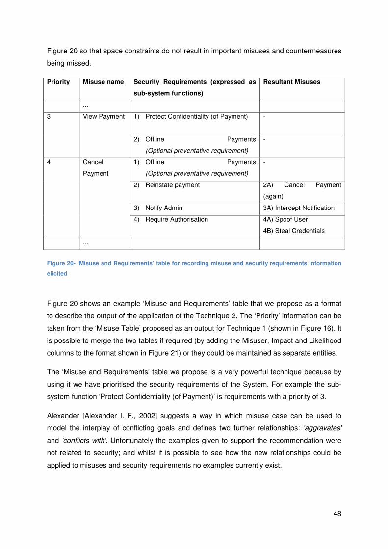
48
Figure 20 so that space constraints do not result in important misuses and countermeasures
being missed.
Priority Misuse name Security Requirements (expressed as
sub-system functions)
Resultant Misuses
...
3 View Payment 1) Protect Confidentiality (of Payment) -
2) Offline Payments
(Optional preventative requirement)
-
4 Cancel
Payment
1) Offline Payments
(Optional preventative requirement)
-
2) Reinstate payment 2A) Cancel Payment
(again)
3) Notify Admin 3A) Intercept Notification
4) Require Authorisation 4A) Spoof User
4B) Steal Credentials
...
Figure 20- ‘Misuse and Requirements’ table for recording misuse and security requirements information
elicited
Figure 20 shows an example ‘Misuse and Requirements’ table that we propose as a format
to describe the output of the application of the Technique 2. The ‘Priority’ information can be
taken from the ‘Misuse Table’ proposed as an output for Technique 1 (shown in Figure 16). It
is possible to merge the two tables if required (by adding the Misuser, Impact and Likelihood
columns to the format shown in Figure 21) or they could be maintained as separate entities.
The ‘Misuse and Requirements’ table we propose is a very powerful technique because by
using it we have prioritised the security requirements of the System. For example the sub-
system function ‘Protect Confidentiality (of Payment)’ is requirements with a priority of 3.
Alexander [Alexander I. F., 2002] suggests a way in which misuse case can be used to
model the interplay of conflicting goals and defines two further relationships: 'aggravates'
and 'conflicts with'. Unfortunately the examples given to support the recommendation were
not related to security; and whilst it is possible to see how the new relationships could be
applied to misuses and security requirements no examples currently exist.

49
6.36.36.36.3 Technique 3Technique 3Technique 3Technique 3---- Eliciting Security Requirements with textual Misuse Eliciting Security Requirements with textual Misuse Eliciting Security Requirements with textual Misuse Eliciting Security Requirements with textual Misuse
Cases Cases Cases Cases
6.3.16.3.16.3.16.3.1 OverviewOverviewOverviewOverview
Textual Misuse cases enable us to describe the misuses in much more detail than
diagrammatic misuse cases. The technique was first proposed by Sindre et al [Sindre &
Opdahl, 2001] who also proposed a template for recording the details of textual misuse
cases. Their ‘Misuse Case Template’ was an amalgamation of two different use case
description templates from Kulak et al [Kulak & Eamonn, 2000] and Cockburn [Cockburn,
2001].
Two years later Sindre et al [Sindre, Firesmith, & Opdhal, 2003] proposed ‘Security Use
Cases’ a new format where misuses (things that should not happen) are embedded in a
security use case (things that need to happen to counter the misuses). The Security Use
Case format was refined by Firesmith [Firesmith, 2003] to make the elicitation of security
requirements more explicit; this format is used as the basis for Technique 3.
Misuse case Templates (distinct from security use cases) were developed further by Sindre
et al [Sindre & Opdahl, 2005] by the addition of more fields to describe the misuses. Some of
these extra fields have been adopted by Technique 3, these are blue text.
The output from applying Technique 3 is a set of Security Use Cases.
6.3.26.3.26.3.26.3.2 Striving for CompletenessStriving for CompletenessStriving for CompletenessStriving for Completeness
The first action in striving for completeness is to being with a set of identified misuses that is
as close to complete as possible. Security Use Cases exist to counter Misuse Cases;
without a complete set of misuse cases in the first instance, one cannot be sure that all
misuses have been taken into account.
The second action in striving for completeness is to consider whether all possible Security
Use Cases have been identified. Firesmith [Firesmith, 2003] names his example security use
cases after the ‘Security Properties’ (defined in ISO13335-1 [ISO, 2004]). We propose that
the Security Properties are used as a ‘Foundation Set’ for the identification of Security Use
Cases.

50
The third action in striving for completeness is to consider whether all possible security
requirements within the Security Use Cases have been identified. To achieve this we
recommend the following:
• Each of the relationships proposed in Section 6.2.2 and shown in
Figure 18 should be considered for each misuse so that relevant requirements will be
identified for: prevention, mitigation, detection and response.
• The Security Services in ISO7498-2 [ISO, 1989] are referred to to provide more
specific security requirements where appropriate. We illustrate this proposal with an
example for Data Confidentiality.
(Data Confidentiality) Service Explanation
Connection confidentiality Sometimes known as protecting
‘confidentiality of data in transit’
Connectionless confidentiality Sometimes known as protecting
‘confidentiality of data at rest’
Selective field confidentiality Protection of single field of data (either in
transit or at rest)
Traffic flow confidentiality Protection of information that might be
derived from traffic flows
Figure 21- Security Services relating to Data Confidentiality
Figure 21 explains the Security Services relating to Data Confidentiality detailed in
ISO7498-2 [ISO, 1989]. During the preparation of the security use case for ‘Data
Confidentiality’ each related Security Service in
Figure 21 was considered in turn to decide whether it should be specified in a
security requirement. As a result there are separate requirements in the security use
case in Figure 23 for ‘data at rest’ and ‘data in transit’. And for ‘Selective field
confidentiality’ in the security use case in Figure 24.
6.3.36.3.36.3.36.3.3 PrePrePrePre----conditions conditions conditions conditions
Application of Technique 3 showed that the following preconditions must be met:
1) As a minimum a set of diagrammatic use cases are required (textual use cases are
also needed but can be developed as part of the application of Technique 3);

51
2) Assuming that the system has no existing security (requirements or mechanisms) so
as not to constrain the identification of potential misuses;
3) Beginning the analysis with the output from applying Technique 1 that is as complete
as possible; because textual descriptions contain much more detail than their
diagrammatic counterparts it is logical to focus on the misuses of greatest concern.
6.3.46.3.46.3.46.3.4 Application Application Application Application
Two security use cases have been derived from the Case Study to demonstrate Technique
3. The first ‘Data Confidentiality’ is included in this Section and the second ‘Elevation of
Privilege’ is included in Appendix B.
For convenience of presentation the ‘Data Confidentiality’ security use case has been
separated into 3 Parts which are discussed separately; normally such a separation would not
be made and it would be a single entity. The numbers on Figure 22, Figure 23 and Figure 24
highlight areas of interest which are discussed in more detail in the text, the fields where the
text is in blue were adopted from Sindre et al [Sindre & Opdahl, 2005] and the fields and text
in red are offered by this Paper to provide extra information.
Security Use Case: Data Confidentiality
Security Use Case Path: Attempted Viewing of payment data
Security Threat: The Misuser is able to see how much the User gets paid
Misuser Profile: Competitors have access to IT Contractors therefore it reasonable to
assume a high degree of technical competence (capability). It is likely that they would want to
see how much their counterparts were getting paid (motivation)
Trigger: Always True. Can happen at any time
Preconditions:
1) There must be some way of observing the data either at rest or in transit
2) User must have submitted an Invoice, which has been approved by the Administrator
Prevention Requirements:
1) The System must not make online payments; an offline process will be used instead
Figure 22- Security Use Case for Data Confidentiality of Payment Data (Part 1)
Figure 22 illustrates the fields in a security use case that provide the contextual information
and the preconditions before the analysis of actions begins in Part 2 (in Figure 23). The
following points are relevant:
1
2
3

52
1) The name of the Security Use Case should be that of a Security Property as
discussed in Section 6.3.2;
2) The ‘Misuser Profile’ field has been included so information about the potential threat
sources can be conveyed with the security use case (in this example we consider
Competitors to be the most likely Misusers);
3) We propose the inclusion of a ‘Prevention Requirements’ field because it captures
the requirements that could be used to prevent the misuse completely. In this
example disabling the ability to make payments online is unlikely to be an acceptable
solution, but it should at least be captured as an option nonetheless.
Part 2 of the security use case encapsulates: uses, misuses and security requirements in a
table as follows.
IT Contractor
Interactions
HR
Administrator
Interactions
Misuser
Interactions
System Requirements
System
Interactions System Actions
Administrator
determines the
amount to be
paid to the User
Misuser attempts
to observe the
payment data
stored on the
System
NOTE: Could be
an external party
or an internal user
1) The System
must protect the
confidentiality of
the payment data
whilst it is at rest
2) The System
must log any
attempted access
to payment data
The Administrator
makes the
payment
Misuser attempts
to observe the
payment data
transmitted by the
System
The System must
protect the
confidentiality of
the payment data
whilst it is in transit
User receives
payment
Figure 23- Security Use Case for Data Confidentiality of Payment Data (Part 2)
4
5

53
Figure 23 shows the interactions between the Actors (IT Contractors, HR Administrators and
Misusers) and the System. The cells should be read in order (i.e. left to right, top to bottom).
The following points are relevant:
4) The columns in the table enable the actions (described in the cells of the table) to be
attributed an individual Actor or the System. The rows of the table represent ‘time
slots’ of when the actions are done; hence the sequence of actions can be captured;
5) A major feature of the security use case is its use in communicating security
requirements. The actions described in the ‘System Actions’ column are the System’s
security requirements. Firesmith [Firesmith, 2003] recommends the use of the key
word ‘shall’ to distinguish the security requirements from the rest of the text. We have
used the key word ‘must’ to be consistent with the MoSCoW requirements
description method defined in Section 2.4.3;
Post Conditions:
1) The System must have prevented the Misuser from viewing the payment data at rest
2) The System must have prevented the Misuser from viewing the payment data in transit
Mitigation guarantee: Verified during the ‘Testing’ workflow at the end of each iteration of the
System Development Lifecycle
Technology and data variations: The System could implement 'selective field confidentiality'
as specified in ISO7498-2 for the payment data at rest
NOTE: Access control also required between internal users such that the confidentiality of the
data applies to the User and the Administrator.
Figure 24- Security Use Case for Data Confidentiality of Payment Data (Part 3)
Figure 24 illustrates the fields in security use case that provide the post conditions and other
relevant considerations.
6) The use of the key word ‘could’ is used to denote security requirements that are not
necessarily mandatory as defined in Section 2.4.3.
6.3.4.16.3.4.16.3.4.16.3.4.1 Analysing the Requirements Analysing the Requirements Analysing the Requirements Analysing the Requirements identifiedidentifiedidentifiedidentified
The Requirements identified in ‘System Actions’ column in Part 2 (Figure 23) are functional
requirements (e.g. The System must protect the confidentiality of the payment data whilst it
is in transit).
6

54
The Requirements identified in the ‘Post conditions’ field in Part 3 (Figure 24) are non-
functional requirements (e.g. The System must have prevented the Misuser from viewing the
payment data at rest).
6.3.56.3.56.3.56.3.5 Benefits Benefits Benefits Benefits
Security use cases are capable of capturing more detail than the diagrams used in
Techniques 1 and 2. This enables a more in-depth analysis and consequently the security
requirements identified by the application of Technique 3 are more comprehensive.
Furthermore they are already in the form of security requirements (unlike with Technique 2)
so little extra processing is required.
Unlike Techniques 1 and 2 the order in which actions occur can be communicated. This
benefit is built upon by Technique 4.
6.3.66.3.66.3.66.3.6 Limitations Limitations Limitations Limitations
The output from Technique 3 is more detailed than Techniques 1 and 2; hence it requires
more effort to generate. In situations where time and resources are limited it would be
advisable to only create security use cases that counter the highest priority misuses.
Unlike Technique 2, Technique 3 has no way of representing misuses that are enabled by
the introduction of the security requirements. This could be easily resolved by applying
Techniques 2 and 3 in conjunction.
The fields used in Part 1 of the example ‘Data Confidentiality’ security use case in Figure 22
did not consider its priority relative to the other security use cases. Addition of a ‘Priority’ field
determined on the basis of the priorities of the misuses mitigated by the security use case
would resolve this.
6.3.76.3.76.3.76.3.7 Extending TechniqueExtending TechniqueExtending TechniqueExtending Technique 3333
The sequence of events described in the security use cases could be adapted to provide
some Test Scenarios that could be applied to the system to demonstrate whether the
security requirements had been implemented correctly. This suggestion is explored by
Technique 4.

55
6.46.46.46.4 Technique 4Technique 4Technique 4Technique 4---- Adapting Adapting Adapting Adapting Misuse Cases to Provide Test ScenariosMisuse Cases to Provide Test ScenariosMisuse Cases to Provide Test ScenariosMisuse Cases to Provide Test Scenarios
6.4.16.4.16.4.16.4.1 OverviewOverviewOverviewOverview
Braz et al [Braz, Fernandez, & VanHilst, 2008] propose the use of activity diagrams
(explained in Section 5.3) to aid the identification of misuses of the System. They use them
to describe the basic flow of the use case and then to superimpose misuses on the diagram.
Technique 4 is similar to the proposal of Braz et al in that it uses activity diagrams to model
the uses and misuses of a system. However it is different because the emphasis of the
activity diagram is to communicate a Test Scenario which will be followed by a system
Tester during the ‘Testing’ Workflow of the system development lifecycle defined in Section
2.2.
A Test Scenario combines the misuse cases and their mitigations (described in the security
use cases) in an activity diagram. Incorporated in to the Test Scenario are a number of Test
Cases. The Tester will work through the Test Scenario from beginning to end and make a
note of whether each Test Case passed or failed and whether the overall misuse was
possible. Figure 25 illustrates a Test Scenario based on the ‘Data Confidentiality (of
payment data)’ security use case (detailed in Section 6.3.4) and Figure 26 illustrates the
Test Scenario for ‘Privilege Elevation’ (the corresponding security use case is shown in
Appendix B).
6.4.26.4.26.4.26.4.2 IntroducIntroducIntroducIntroducinginginging TechniqueTechniqueTechniqueTechnique 4444
Technique 4 is defined by this Paper to be the production of the Test Scenarios. It does not
include applying the Test Scenarios. Consequently, Technique 4 is treated differently from
the other techniques in this Paper in that it is not applied to the Case Study because to
demonstrate the application of the Test Scenarios would require something tangible to test
against (for example an operational system), which we do not have. Therefore in this Section
we focus on producing some example Test Scenarios.
In terms of the Unified Process (the system development lifecycle described in Section 2.2):
the Test Scenarios for Technique 4 should be produced by ‘Requirements’ and ‘Analysis’
workflows during the ‘Elaboration’ phase. The Test Scenarios will be applied during the
‘Testing’ workflow.
An example Test Scenario is given below in Figure 25.
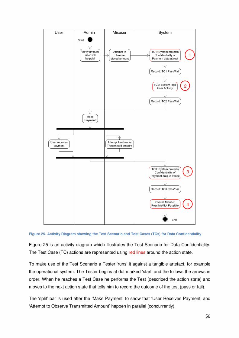
56
SystemMisuserAdminUser
Verify amount
user will
be paid
Attempt to observe
Transmitted amount
Record: TC1 Pass/Fail
User receives
payment
Start
End
Attempt to
observe
stored amount
Make
Payment
TC1: System protects
Confidentiality of
Payment data at rest
TC2: System logs
User Activity
TC3: System protects
Confidentiality of
Payment data in transit
Record: TC2 Pass/Fail
Record: TC3 Pass/Fail
Overall Misuse:
Possible/Not Possible
Figure 25- Activity Diagram showing the Test Scenario and Test Cases (TCs) for Data Confidentiality
Figure 25 is an activity diagram which illustrates the Test Scenario for Data Confidentiality.
The Test Case (TC) actions are represented using red lines around the action state.
To make use of the Test Scenario a Tester ‘runs’ it against a tangible artefact, for example
the operational system. The Tester begins at dot marked ‘start’ and the follows the arrows in
order. When he reaches a Test Case he performs the Test (described the action state) and
moves to the next action state that tells him to record the outcome of the test (pass or fail).
The ‘split’ bar is used after the ‘Make Payment’ to show that ‘User Receives Payment’ and
‘Attempt to Observe Transmitted Amount’ happen in parallel (concurrently).
1
3
2
4

57
The end of the Scenario is represented by the circle containing a dot that is labelled ‘End’. In
the action state just before this point the Tester records whether the overall misuse was
possible or not.
The numbers superimposed on Figure 25 are used to highlight the test cases and the
Overall Test. We note that the four Tests each verify the security requirements identified in
the Security Use Case from Technique 3; this is illustrated below:
1) Test Case 1: The system must protect the confidentiality of payment data while it is
at rest;
2) Test Case 2: The System must log any attempted access to payment data;
3) Test Case 3: The System must protect the confidentiality of payment data whilst it is
in transit;
4) Overall Test: The System must have prevented the Misuser from viewing the
payment data at rest and in transit.
We have just demonstrated how applying the Test Scenarios could be used as way of
verifying that the security requirements have been implemented.
Figure 26 provides a further example Test Scenario, ‘Privilege Elevation’. The numbers
superimposed are used to highlight aspects of interest discussed below:
1) A decision point is necessary after Test Case 2 (System scans upload) to cater for
the two possible outcomes of the test case, represented as the guard conditions:
[malware detected] and [malware not detected].
2) A decision point is needed again after the Misuser (played by the Tester) attempts to
intercept the notification to the Administrator. If he fails the Administrator is notified
and Test Case 5 is passed; otherwise Test Case 5 fails.

58
Figure 26- Activity Diagram showing the Test Scenario for the 'Elevation of Privilege misuse
1
2

59
6.4.36.4.36.4.36.4.3 PrePrePrePre----conditions conditions conditions conditions
The Testing Scenarios prepared using Technique 4 need to be tested against something
tangible. Therefore the ‘Design’ and ‘Implementation’ workflows need to have produced
something to test against (for example: a System Design, or an operational System).
6.4.46.4.46.4.46.4.4 Potential benefits Potential benefits Potential benefits Potential benefits
The significant benefit of Technique 4 is realised when the Test Scenarios it defines are
applied in the ‘Testing’ workflow. By virtue of following the Unified Process the security
requirements will be tested throughout the system lifecycle to verify they have been met
(traceability as discussed in Section 2.2). Consequently the security requirements elicited by
the application of Techniques 2 and 3 can be verified.
A minor benefit is that by using activity diagrams to describe the Test Scenarios there is a
visual representation of the flow of events and which actors are involved that can be easily
interpreted and used by Testers of the System.
6.4.56.4.56.4.56.4.5 Potential lPotential lPotential lPotential limitations imitations imitations imitations
Each Test Scenario needs to be developed just once but it will be applied many times;
hence the time taken to apply the Test Scenario will be the most relevant factor. In situations
where time and resource are limited it is advisable to only test against Test Scenarios for the
highest priority security use cases.
The formatting constraints of the activity diagrams mean that Test Scenarios communicated
in that manner take up a lot of space. To get around this Test Scenarios could be
communicated using text instead; this would follow a similar format to the table used in
security use cases (shown in Figure 23).
6.4.66.4.66.4.66.4.6 Extending Technique 4Extending Technique 4Extending Technique 4Extending Technique 4
The Test Scenario shown in Figure 25 describes the Test Cases in terms of security
properties which are (necessarily) unspecific. As more information about the design and
implementation details of the system becomes available the Test Cases can be updated to
contain those details. The overall Test Scenario will however remain the same.
As an example the action for Test Case 3 would become “The SSL encryption used by the
System protects the confidentiality of the payment data in transit”. It is possible to be specific
60
by the time the system is implemented because we know that SSL encryption has been
used.
6.56.56.56.5 SummarySummarySummarySummary
This section has demonstrated with the aid of the Case Study how it is possible to begin with
a set of use cases for a system and apply a range of misuse case Techniques sequentially
to achieve the following:
• (Technique 1) Identify an top-level, prioritised set of misuses
• (Technique 2) Elicit an initial set of sub-system functions (that describe security
requirements) for the System which can be prioritised.
• (Technique 3) Elicit the security requirements for the System and encapsulate them
in Security Use Cases, which we suggest can also be prioritised.
• (Technique 4) Produce a set of Test Scenarios for the significant misuses that can be
applied throughout the development lifecycle to verify that the important security
requirements have been implemented.
Although the Techniques are considered separately by this Section we have highlighted how
it is possible to use the Techniques sequentially and how useful that can be improving the
security of Information Systems.

61
7777 Misuse Cases in ContextMisuse Cases in ContextMisuse Cases in ContextMisuse Cases in Context
This Section provides a brief discussion on how Misuses Cases fit in to the ‘wider picture’ of
Information Security; considering how they may be used in the future and related techniques
which could be used in conjunction with the Techniques analysed in Section 6.
7.17.17.17.1 Increasing importance of Misuse and Use Cases Increasing importance of Misuse and Use Cases Increasing importance of Misuse and Use Cases Increasing importance of Misuse and Use Cases
Use Cases are already commonplace within the software engineering discipline and various
initiatives are underway to develop tools that will automatically generate software from
models such as use cases. An example of this is the Model Driven Architecture (MDA)
described in [Mellor, Scott, Uhl, & Weise, 2004]. This is symptomatic of a trend in the
software industry of moving away from the bits and the bytes towards the ultimate goal of
specifying an Information System purely in terms of its requirements.
Misuse cases give Security Professionals a way of analysing security at the level of use
cases so, as the effort of system developers continues its shift towards requirements
(described in part by use cases); Misuse Cases are likely to become more and more
important to Security Professionals.
7.27.27.27.2 Limitations of Misuse Limitations of Misuse Limitations of Misuse Limitations of Misuse CasesCasesCasesCases
Misuse Cases are a powerful technique, but they should not be applied in isolation. The
following activities should be considered to support the application of Misuse Cases:
• A formal Asset Identification and Categorisation should be done to identify all of the
information assets in the System and their relative value;
• A formal Threat Source Analysis should be done to understand the capability and
motivation of the Threat Sources;
• A formal check should be done to ensure that any important security requirements
have not been overlooked. This could be achieved by doing a comparison of:
o The security requirements identified when applying Techniques 2 and 3 and;
o The security functional requirements (SFRs) in Common Criteria [CC, 2005,
Part 2] as the Foundation Set for security requirements.
62
7.37.37.37.3 ReReReRe----use of use of use of use of MMMMisuse Casesisuse Casesisuse Casesisuse Cases
In 2003 Sindre et al [Sindre, Firesmith, & Opdhal, 2003] claimed that work was underway to
develop a library of re-usable misuse cases. However if such libraries do already exist they
are not publicly available.
The emphasis in this Paper was on applying the Four Techniques based on Misuse Cases
to understand how they could be used to improve the security of Information Systems; we
did not explicitly consider.
7.47.47.47.4 Related WorkRelated WorkRelated WorkRelated Work
There is a body of work in Lancaster University developing technique called ‘Executable
misuse cases’ [Whittle, Wijesekera, & Hartong, 2008]. This work is in the early stages of
development and uses a UML modelling technique to generate what are called Finite State
Machines (FSMs) to represent the countermeasures to misuse. These FSMs are used in the
Testing of the system to give the developer confidence that they counter the misuse they are
intended for. The greatest benefit of this work is that there is a tool (MUCSIM6) that
automates the testing of the FSMs. Whilst this is a very interesting and promising approach
very little work has been done to make the approach scalable to large systems (Whittle,
2008).
Microsoft Threat Modelling [Swiderski & Snyder, 2004] is another technique that aids in the
identification of Threats and Risks to Information Systems. Unlike the Misuse cases
Techniques applied in this Paper, it does not take into account Use Cases for the System
and how they provide opportunities for misuse. The STRIDE classification used in Section
6.1.6 was adopted from Microsoft’s Threat Modelling.
Attack trees are a technique described by Schneier in [Schneier, 2004, Chapter 21] and are
a way of analysing what attacks are possible on a system. Because attack trees were
designed to describe attacks on operational systems they contain very system specific
information. As a result this approach could be an effective compliment to the Test
Scenarios developed by applying Technique 4.
6 MUCSIM (Misuse Case Simulator)

63
7.57.57.57.5 SummarySummarySummarySummary
In this Section we have provided a brief discussion that helps to put the Techniques
analysed in Section 6 into context. Significantly we have recommended three activities that
should be used in conjunction with the Misuse Case techniques to formalise their output
namely:
• Asset Identification and Categorisation;
• Threat Source Analysis;
• Comparison of: the security requirements derived from misuses with a ‘Foundation
set’;
We have also considered related techniques in context of the techniques we have analysed.

64
8888 ConclusionConclusionConclusionConclusion
This Section provides the reader with a summary of the main findings from the dissertation
and considers how it met the original Aim and Objectives. It finishes with a brief
consideration of the Future work to come out of this dissertation.
8.18.18.18.1 Summary of FindingsSummary of FindingsSummary of FindingsSummary of Findings
Section 2 introduced Information Systems and the aspects that are important for this Paper.
The Unified Process was introduced as a way of modelling the development of Information
Systems. The reader was provided with background information on requirements for
Information Systems.
Section 3 introduced Security in Information Systems. It defined the significant security-
related terms and explained the importance of making a distinction between security
requirements which should not constrain the solution and security mechanisms that are
needed to implement the security properties described in the security requirements.
Section 4 outlined the IT Contractor Management System Case Study that is used
throughout the Paper.
Section 5 provided an introduction to use cases, misuses cases and scenarios, which form
the basis of the Techniques applied in Section 6.
Section 6 applied the four Techniques based on Misuse Cases to the IT Contractor
Management Case Study. Demonstrating how it is possible to begin with a set of Use Cases
for a system and, by applying the techniques, achieve the following:
• Identify a prioritised set of top-level misuses for the Information System
• Elicit a set of (prioritised) Security Requirements by applying two techniques:
o Diagrammatic misuse cases that identify significant misuses, sub-system
functions to counter the misuses and any resultant misuses of the sub-system
functions.
o Textual misuses encapsulated with security requirements in a security use
case that provides much more detail than the diagrammatic technique.

65
• Prepare a set of Test Scenarios for the higher priority misuses, using their Security
Use Cases as a starting point.
Section 7: Misuse Cases were considered in the context of the wider picture of information
security and three activities were identified that should be applied in conjunction with Misuse
Case techniques to formalise their output.
8.28.28.28.2 ReReReRelating findings to the original Aim and Objectivlating findings to the original Aim and Objectivlating findings to the original Aim and Objectivlating findings to the original Aim and Objectiveseseses
8.2.18.2.18.2.18.2.1 AimAimAimAim
This dissertation has met the main Aim set out in Section 1.2.1 by demonstrating how the
Techniques derived from Misuse Cases can be used to address at the earliest opportunity in
the Information System Development Lifecycle; and developing some Test Scenarios.
8.2.28.2.28.2.28.2.2 PreliminaryPreliminaryPreliminaryPreliminary ObjectivesObjectivesObjectivesObjectives
All of the Preliminary Objectives were met successfully by Sections 2, 3, 4 and 5; providing
the necessary background to enable the Main Objective to be met.
8.2.38.2.38.2.38.2.3 Main ObjectiveMain ObjectiveMain ObjectiveMain Objective
The overall Main Objective was met by applying variations of the Misuse Case Technique to
the IT Contractor Management Case Study to demonstrate how it can ‘add value’ to the
Security of Information Systems.
Each of the sub-objectives of the Main Objective is considered in Figure 27 below:

66
Sub-Objective Technique How it ‘adds value’
security
Proposed Modifications
Using Misuse
Cases to Identify
potential top-level
Misuses of an
Information
System
Technique
1
Communicates
potential top-level
misuses to
developers (in order
of priority)
a) Use a ‘Misuse Table’ to record and
prioritise misuses
b) Use the STRIDE Technique to strive
from completeness
Using Misuse
Cases to Elicit
Security
Requirements for
an Information
System
Technique
2
Identifies and
prioritises sub-
system functions and
subsequent misuses
a) Using the relationships: {prevent,
mitigate, detect, respond} to strive for
completeness
b) Use a ‘Misuse and Requirements’
table to record and prioritise the
misuses and their requirements
Technique
3
Identifies security
requirements and
encapsulates them
with misuses in a
Security Use Case
a) Using the Security Services defined in
ISO7498-2 to strive for completeness
b) Prioritising the security use cases on
the basis of the priorities of the
misuses they mitigate
Proposing a
technique to
develop Tests to
verify that
Security
Requirements
have been met
Technique
4
Provides a method to
develop Test
Scenarios that can
be used in verifying
that Security
Requirements are
met
a) Addition of more system specific
information as the Information System
develops
Considering
Misuse Cases in
the context of the
‘wider picture’
N/A Understand better
how Misuse Cases
can be used by
Security
Professionals
N/A
Figure 27- How the sub-objectives were achieved

67
The Information in Figure 27 demonstrates that each sub-objective has been successfully
met by this dissertation. The red text is used to highlight the techniques and modifications
we have proposed in this dissertation to go beyond simply achieving the sub-objective and
enhance the techniques to make their application even more valuable.
In Summary: the Aim and all of the Objectives identified in the Introduction have been
satisfied.
8.38.38.38.3 Further WorkFurther WorkFurther WorkFurther Work from this Dissertationfrom this Dissertationfrom this Dissertationfrom this Dissertation
The possibility of using Misuse Cases to model conflicting requirements is an area where
Techniques could be developed that could analyse the trade-offs between security and
usability requirements to enable developers of Information Systems to decide which factor
was most important on a case-by-case basis.
Developing a library of re-usable misuse cases would be a significant contribution to the
area. Schumacher et al [Schumacher, Fernandez-Buglioni, Hybertson, Buschmann, &
Sommerlad, 2006] propose the use of Patterns (solutions to common problems in a given
context) to do this. They recognise that “use cases, threatened by misuse cases that are
mitigated by security use cases, correspond, respectively to the context, problem and
solution parts of a pattern”.
The Techniques in this Paper could be made even more powerful if they could be combined
with the work on Executable Misuse Cases discussed in Section 7.4. Automating the
application of techniques would help significantly in the Quest to make securing Information
Systems faster and smarter.
There is no documented study of a ‘real world’ application of Misuse Case techniques;
hence it was necessary to apply the Techniques to the hypothetical case study in this
dissertation. In applying the Techniques we proposed a number of enhancements. Trialling
the modified Techniques in the development of a ‘real world’ Information System would
provide invaluable feedback on how effective they are.

68
BibliographyBibliographyBibliographyBibliography
Alexander, I. F. (2003). Misuse Cases: use cases with hostile intent. IEEE Software , 58-66.
Alexander, I. F. (2002). Modelling the interplay of conflicting goals with use and misuse
cases. Paper presented at REFSQ, Essen, 9th-10th September , 145-152.
Bittner, K., & Spence, I. (2003). Use Case Modelling. Boston: Pearson Eduction.
Boswell, T., & Hill, S. (2006, March 31). VLA-Centric Evaluation: Improving Evaluations by
Putting Vulnerabilities First. Retrieved August 26, 2008, from www.cesg.gov.uk:
http://www.cesg.gov.uk/products_services/iacs/cc_and_itsec/media/formal-docs/vla-
centric_evaluation.pdf
Braz, F. A., Fernandez, E. B., & VanHilst, M. (2008). Eliciting Security Requirements through
Misuse Activities. Available from www.securitypatterns.org.
BSI. (2005, November). Retrieved September 1, 2008, from The German Federal Office for
Information Security (BSI): http://www.bsi.bund.de/english/gshb/download/index.htm
CC. (2005). ISO 15408:2005 Common Criteria for Information Technology Security
Evaluation version 3.1. International Standards Organisation.
CESG. (2007, July). Information Security Standard 1- Part 1. Retrieved August 29, 2008,
from www.cesg.gsi.gov.uk: www.cesg.gsi.gov.uk/iabookstore/
Clegg, D., & Barker, R. (1994). Case Method: Fast-Track - A RAD Approach (Case Method).
Addison Wesley.
Cockburn, A. (2001). Writing Effective Use Cases. Addison-Wesley.
Davis, A. M. (1993). Software Requirements: Objects, Functions and States. Prentice-Hall.
Firesmith, D. (2003). Security Use Cases. Journal of Object Technology , 2 (3), 53-64.
Fowler, M. (2004). UML Distilled 3rd Edition- A brief Guide to the Standard Modelling
Language. Boston: Pearson Education Inc.
Grance, T., Hash, J., & Stevens, M. (2004). NIST SP800-64- Security Considerations in the
Information System Development Life Cycle- Recommendations of the National Institute of
Standards and Technology. National Insitute of Standards and Technology (NIST).

69
ISO. (2004). ISO13335-1:2004 Information technology -- Security techniques -- Management
of information and communications technology security -- Part 1: Concepts and models for
information and communications technology security management. International Standards
Organisation.
ISO. (1989). ISO7498-2:1989 Information Processing Systems- Open Systems
Interconnection- Basic Reference Model- Part 2: Security architecture. International
Standards Organisation.
Ivar Jacobson Consulting. (2005). Use-Case Modelling Course Notes. Use-Case Modelling .
Ivar Jacobson International.
Jacobson, I. (1987). Object oriented development in an industrial environment. Object-
Oriented Programming Systems, Languages and Applications .
Jacobson, I., Booch, G., & Rumbaugh, J. (1999). The Unified Software Development
Process. Reading: Addison Wesley.
Jacobson, I., Ericsson, M., & Jacobson, A. (1995). The Object Advantage- Business Process
Engineering with Object Technology. New York: ACM Press Books.
Kivistö, K. (2000, December). A Third Generation Object-Oriented Process Model: Roles
and Architectures in Focus. Retrieved August 28, 2008, from University of Oulu, Finland:
http://herkules.oulu.fi/isbn9514258371/html/c199.html
Kulak, D., & Eamonn, G. (2000). Use Cases: Requirements in Context. ACM Press.
Matthews, B. E. (2003, December). Addressing Security Concerns in the Early Stages of the
Project Lifecycle. Retrieved August 30, 2008, from http://handle.dtic.mil/100.2/ADA419396
Matulevičius, R., Mayer, N., & Heymans, P. (2008). Alignment of Misuse Cases with Security
Risk Management. Third International Conference on Availability, Reliability and Security,
2008. ARES 08. (pp. 1397-1404). Barcelona: IEEE.
Mayer, N., Patrick, H., & Matulevičius, R. (2007). Design of a Modelling Language for
Information System Security Risk Management. 1st International Conference on Research
Challenges in Information Science (RCIS 2007). Ouarzazate, Morocco.
McDermott, J., & Fox, C. (1999). Using Abuse Case Models for Security Requirements
Analysis. Computer Security Applications Conference, 1999. (ACSAC '99) Proceedings.
15th Annual (pp. 55-64). Pheonix: IEEE.
70
McGraw, G. (2006). Software Security- Building Security In. Boston: Pearson Education.
McGraw, G., & Felten, E. (1999). Securing Java: Getting Down to Business with Mobile
Code. New York: John Wiley & Sons.
Mellor, S. J., Scott, K., Uhl, A., & Weise, D. (2004). MDA Distilled- Principles of Model-Driven
Architecture. Boston: Pearson Education.
Pauli, J., & Xu, D. (2006). Integrating Functional and Security Requirements with Use Case
Decomposition. Proceedings of the 11th IEEE International Conference on Engineering of
Complex Computer Systems (ICECCS'06). IEEE.
Røstad, L. (2006). An extended misuse case notation: Including vulnerabilities and the
Insider Threat. In Proceedings of the Twelfth Working Conference on Requirements
Engineering: Foundation for Software Quality (REFSQ’06). Luxembourg.
Schneier, B. (2004). Secrets & Lies- Digital Security in a Networked World (with new
information post-9/11 security). Indianapolis: Wiley Inc.
Schumacher, M., Fernandez-Buglioni, E., Hybertson, D., Buschmann, F., & Sommerlad, P.
(2006). Security Patterns- Integrating Security and Systems Engineering. Chichster: John
Wiley and Sons.
Shostack, A. (2007, September 11th). The Secure Development Lifecycle- STRIDE chart .
Retrieved August 21st, 2008, from Microsort MSDN Blogs:
http://blogs.msdn.com/sdl/archive/2007/09/11/stride-chart.aspx
Sindre, G., & Opdahl, A. L. (2001). Capturing Security Requirements through Misuse Cases.
Retrieved July 23, 2008, from Norsk Informatikkonferanse: www.nik.no/2001/21-sindre.pdf
Sindre, G., & Opdahl, A. L. (2005). Eliciting security requirements with misuse cases.
Requirements Engineering , 10, 34-44.
Sindre, G., Firesmith, D. G., & Opdhal, A. L. (2003). A Reuse-based Approach to
Determining Security Requirements. REFSQ'03 Pre-proceedings (pp. 106-114).
Klagenfurt/Velden: REFSQ.
Swiderski, F., & Snyder, W. (2004). Threat Modelling. Redmond, Washington: Microsoft
Press.
Tipton, W. H. (2004). Population and Maintenance of the Department of the Interior
Enterprise Architecture Repository. OCIO DIRECTIVE 2004-010 .
71
Whittle, J. (2008, June). Presentation on Executable Misuse Cases. (J. Whittle, Performer)
CESG Technical Panel, Cheltenham.
Whittle, J., Wijesekera, D., & Hartong, M. (2008, May). Executable Misuse Cases for
Modelling Security Concerns. ICSE , 10-18.

72
Appendix AAppendix AAppendix AAppendix A---- Use Case for the IT Contractor Management SystemUse Case for the IT Contractor Management SystemUse Case for the IT Contractor Management SystemUse Case for the IT Contractor Management System
Figure A1- Complete Use Case for the IT Contractor Management System Case Study

73
Appendix BAppendix BAppendix BAppendix B---- ‘Elevation of Privileges’ ‘Elevation of Privileges’ ‘Elevation of Privileges’ ‘Elevation of Privileges’ Security Use CaseSecurity Use CaseSecurity Use CaseSecurity Use Case
Security Use Case: Authorisation
Security Use Case Path: Attempted Elevation of Privileges
Security Threat: The User becomes a Misuses and bypasses Authorisation Controls to obtain the privileges of the Administrator
Misuser Profile: Users are IT Contractors therefore it reasonable to assume a high degree of technical competence (capability). It is unlikely that they would be motivated to conduct the misuse, unless they were disaffected for some reason.
Trigger: Always True. This can happen at any time
Preconditions: 1) Misuser is authorised by the System as a User 2) Misuse is able to upload data of their choosing to the System
Prevention Requirements: 1) The System must only permit on site administration of the System 2) The System must not allow Users to upload information of their choosing to the system
IT Contractor Interactions
HR Administrator Interactions
Misuser Interactions
System Requirements
System Interactions System Actions
The User authenticates to the System and is authorised as a User
User (now Misuser) uploads a malicious program to the System
1) The System must scan all uploaded data for malicious content 2) The System must log User transactions
Misuser attempts to execute malicious program and gain Administrator authorisation
The System could alert other Administrators that an Elevation of Privilege has occurred
The System must log that an Elevation of Privilege has occurred
Administrators investigate the event, if it unexpected consider shutting down the System
Misuser attempts to intercept notification
The System must require notification of receipt for any alerts
Misuser attempts to cover their tracks by deleting system logs
The System log must be append only (no entries can be deleted)
Post Conditions: 1) The System should have prevented the User elevating their privileges 2) The System must have detected and responded to the User attempting to elevate their privileges
Mitigation guarantee: Verified by testing at each stage in the System Development Lifecycle
Technology and data variations: If zero-day attacks are used it is highly unlikely it will be possible to prevent the attack (hence the importance of detection and response)
Figure B1- Elevation of Privilege Security Use Case


