
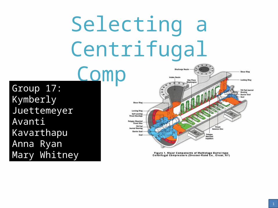
Selecting a Centrifugal Compressor
Group 17:Kymberly JuettemeyerAvanti KavarthapuAnna RyanMary Whitney
Accss the link below for a dynamic version of this presentation:
Centrifugal compressor multistage axial type. 2009. Oil Free Air. Pneumotech Inc. Web. 25 Nov. 2013.
1
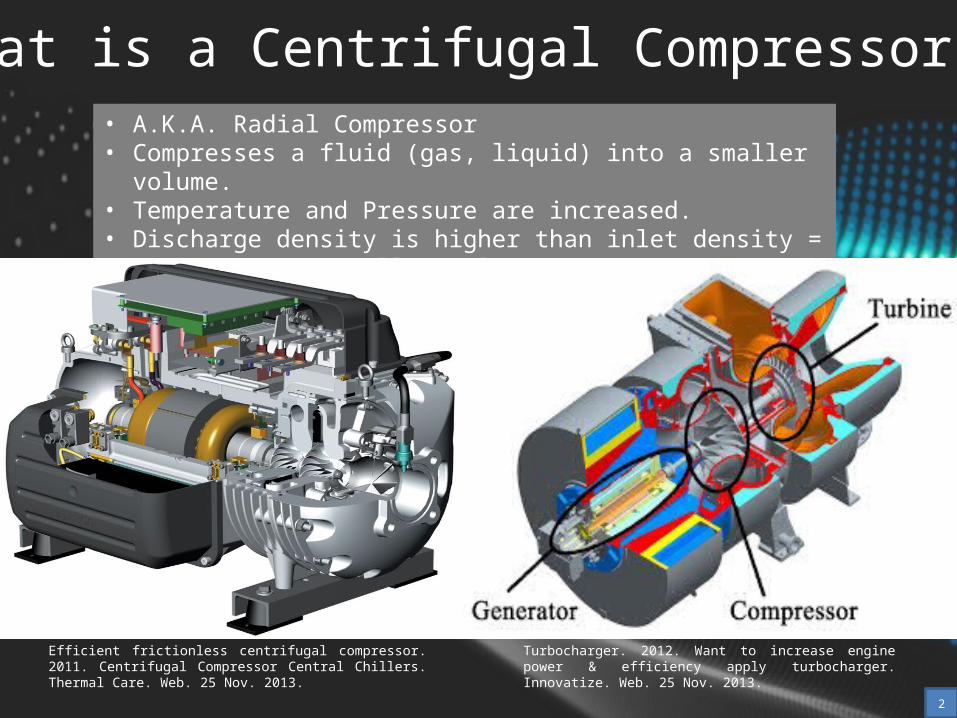
What is a Centrifugal Compressor?• A.K.A. Radial Compressor• Compresses a fluid (gas, liquid) into a smaller volume.• Temperature and Pressure are increased.• Discharge density is higher than inlet density = mass occupies smaller
value = COMPRESSION
Efficient frictionless centrifugal compressor. 2011. Centrifugal Compressor Central Chillers. Thermal Care. Web. 25 Nov. 2013.
Turbocharger. 2012. Want to increase engine power & efficiency apply turbocharger. Innovatize. Web. 25 Nov. 2013.
2
How does it work?
BCL Series Centrifugal Compressor. 2009.
BCL-Vertical Split Casing Series. V-FLO
Group of Companies. Web. 25 Nov. 2013.
Video:
Single Shaft and Overhung Centrifugal
Compressors. Kobelco. Web. 28 Nov. 2013.
https://www.youtube.com/watch?v=s-bbAoxZmBg
3
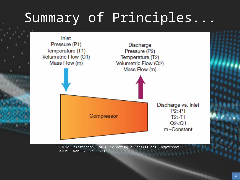
Summary of Principles...
Fluid Compression. 2013. Selecting a Centrifugal Compressor. AIChE. Web. 25 Nov. 2013.
4
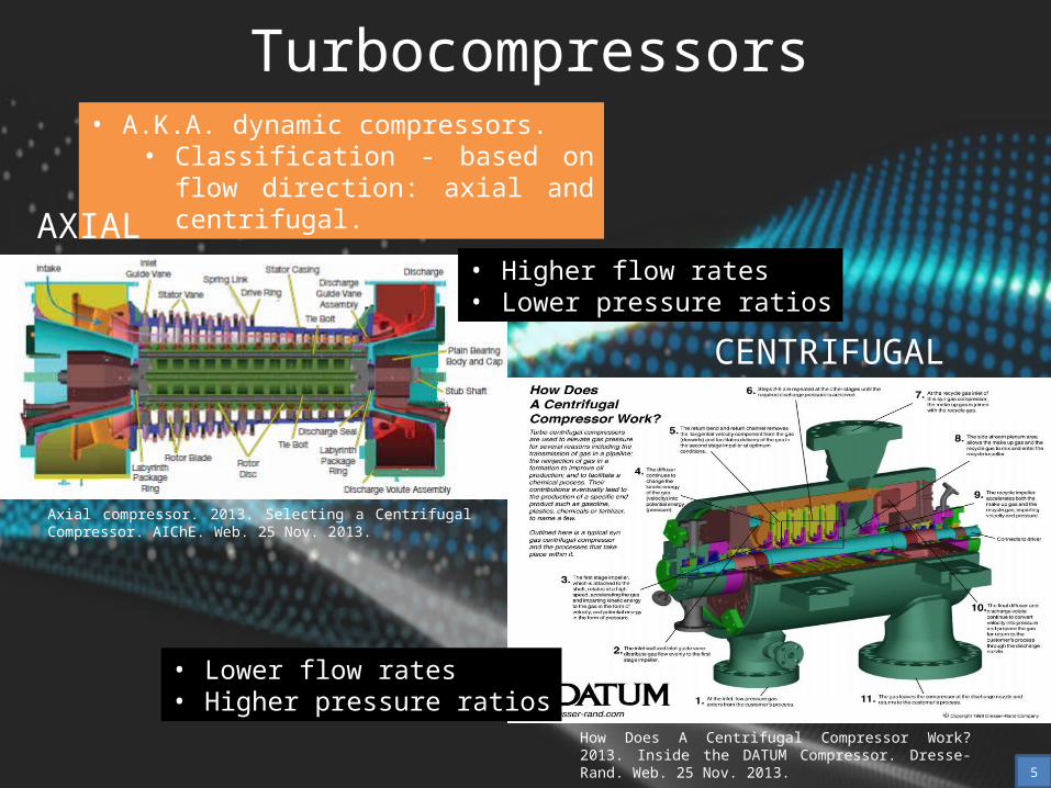
Turbocompressors• A.K.A. dynamic compressors.
• Classification - based on flow direction: axial and centrifugal.
AXIAL
CENTRIFUGAL
How Does A Centrifugal Compressor Work? 2013. Inside the DATUM Compressor. Dresse-Rand. Web. 25 Nov. 2013.
Axial compressor. 2013. Selecting a Centrifugal Compressor. AIChE. Web. 25 Nov. 2013.
• Higher flow rates• Lower pressure ratios
• Lower flow rates• Higher pressure ratios
5
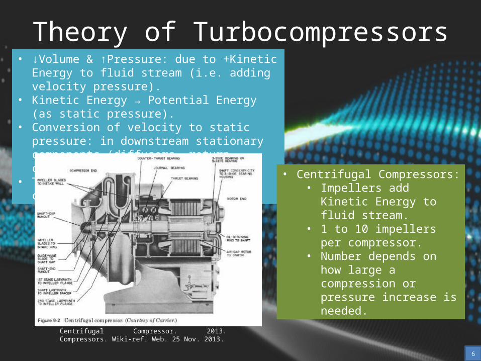
Theory of Turbocompressors• ↓Volume & ↑Pressure: due to +Kinetic Energy to
fluid stream (i.e. adding velocity pressure).• Kinetic Energy → Potential Energy (as static
pressure).• Conversion of velocity to static pressure: in
downstream stationary components (diffusers, return channels, volutes).
• They depend on the style of centrifugal compressor.
Centrifugal Compressor. 2013. Compressors. Wiki-ref. Web. 25 Nov. 2013.
• Centrifugal Compressors:• Impellers add Kinetic Energy
to fluid stream.• 1 to 10 impellers per
compressor.• Number depends on how
large a compression or pressure increase is needed.
6
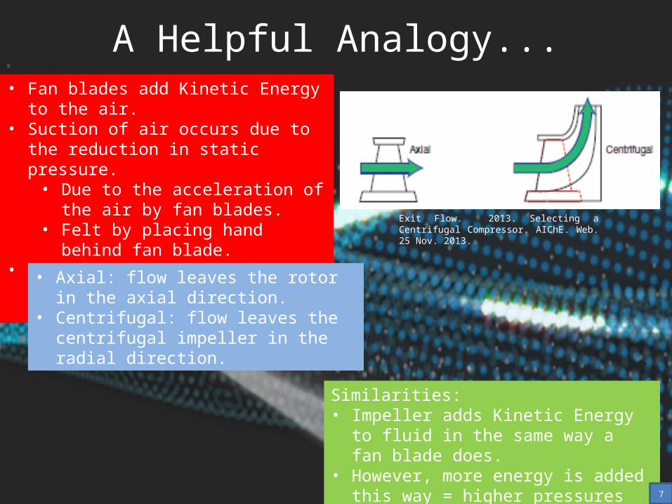
A Helpful Analogy...• Fan blades add Kinetic Energy to the air.• Suction of air occurs due to the reduction in
static pressure.• Due to the acceleration of the air by
fan blades.• Felt by placing hand behind fan blade.
• More fans = more Kinetic Energy added to the air (or any fluid).
Exit Flow. 2013. Selecting a Centrifugal Compressor. AIChE. Web. 25 Nov. 2013.
• Axial: flow leaves the rotor in the axial direction.
• Centrifugal: flow leaves the centrifugal impeller in the radial direction.
Similarities:• Impeller adds Kinetic Energy to fluid in the
same way a fan blade does.• However, more energy is added this way =
higher pressures are achieved.7
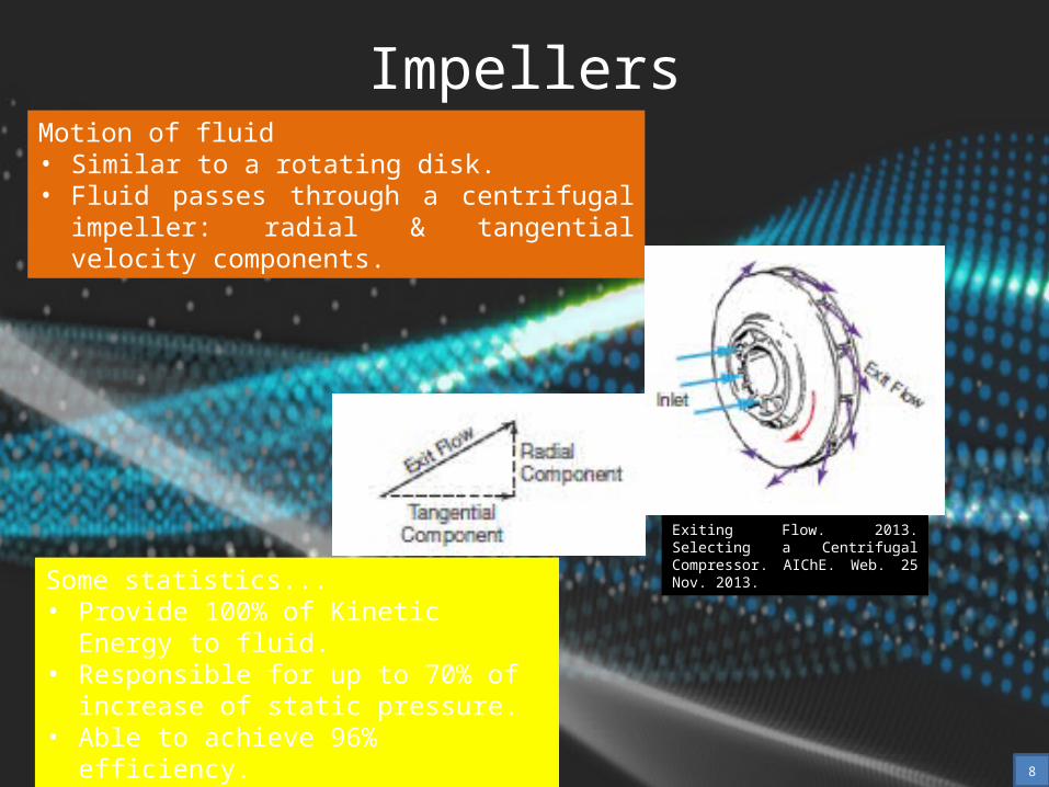
Motion of fluid• Similar to a rotating disk.• Fluid passes through a centrifugal impeller: radial &
tangential velocity components.
Impellers
Exiting Flow. 2013. Selecting a Centrifugal Compressor. AIChE. Web. 25 Nov. 2013.
Some statistics...• Provide 100% of Kinetic Energy to fluid.• Responsible for up to 70% of increase of
static pressure.• Able to achieve 96% efficiency.
8
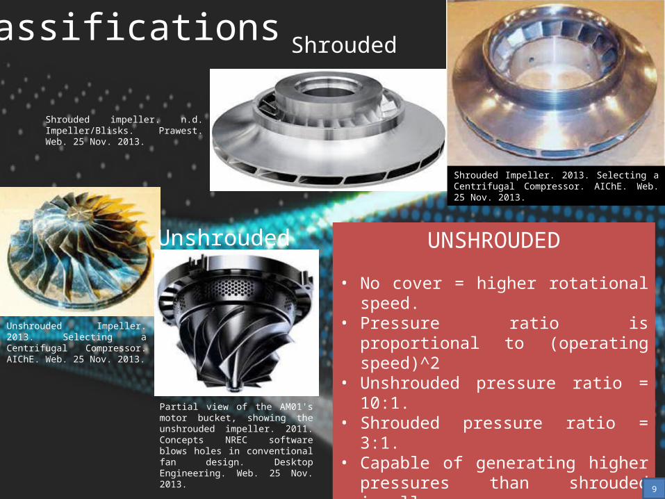
Classifications Shrouded
Shrouded impeller. n.d. Impeller/Blisks. Prawest. Web. 25 Nov. 2013.
Shrouded Impeller. 2013. Selecting a Centrifugal Compressor. AIChE. Web. 25 Nov. 2013.
Partial view of the AM01's motor bucket, showing the unshrouded impeller. 2011. Concepts NREC software blows holes in conventional fan design. Desktop Engineering. Web. 25 Nov. 2013.
Unshrouded Impeller. 2013. Selecting a Centrifugal Compressor. AIChE. Web. 25 Nov. 2013.
Unshrouded UNSHROUDED
• No cover = higher rotational speed.• Pressure ratio is proportional to (operating
speed)^2• Unshrouded pressure ratio = 10:1.• Shrouded pressure ratio = 3:1.• Capable of generating higher pressures
than shrouded impellers.• Lower efficiency due tip leakage (i.e. flow
leaks over the rotating blades), which is not seen in shrouded impeller.
9
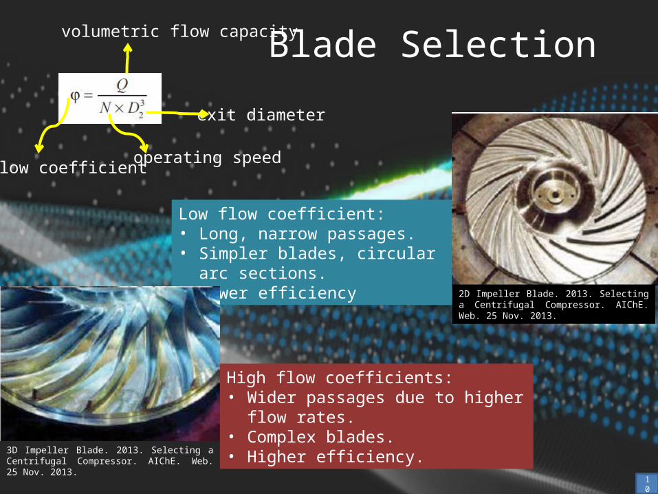
Low flow coefficient:• Long, narrow passages.• Simpler blades, circular arc sections.• Lower efficiency
Blade Selection
2D Impeller Blade. 2013. Selecting a Centrifugal Compressor. AIChE. Web. 25 Nov. 2013.
High flow coefficients:• Wider passages due to higher flow rates.• Complex blades.• Higher efficiency.
3D Impeller Blade. 2013. Selecting a Centrifugal Compressor. AIChE. Web. 25 Nov. 2013.
flow coefficientoperating speed
exit diameter
volumetric flow capacity
10
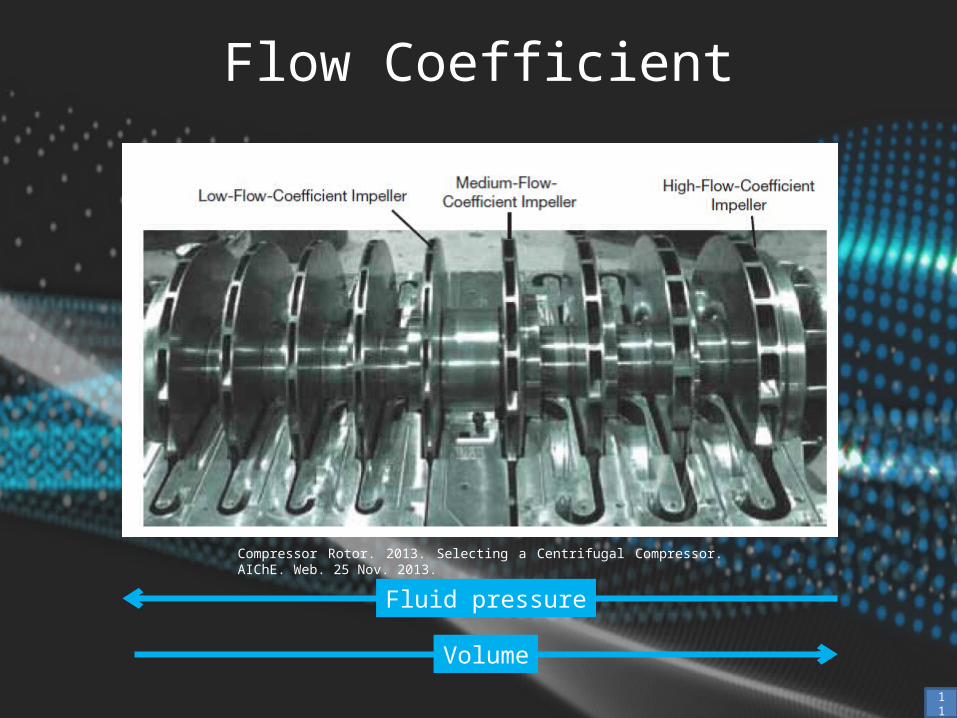
Flow Coefficient
Compressor Rotor. 2013. Selecting a Centrifugal Compressor. AIChE. Web. 25 Nov. 2013.
Fluid pressure
Volume
11
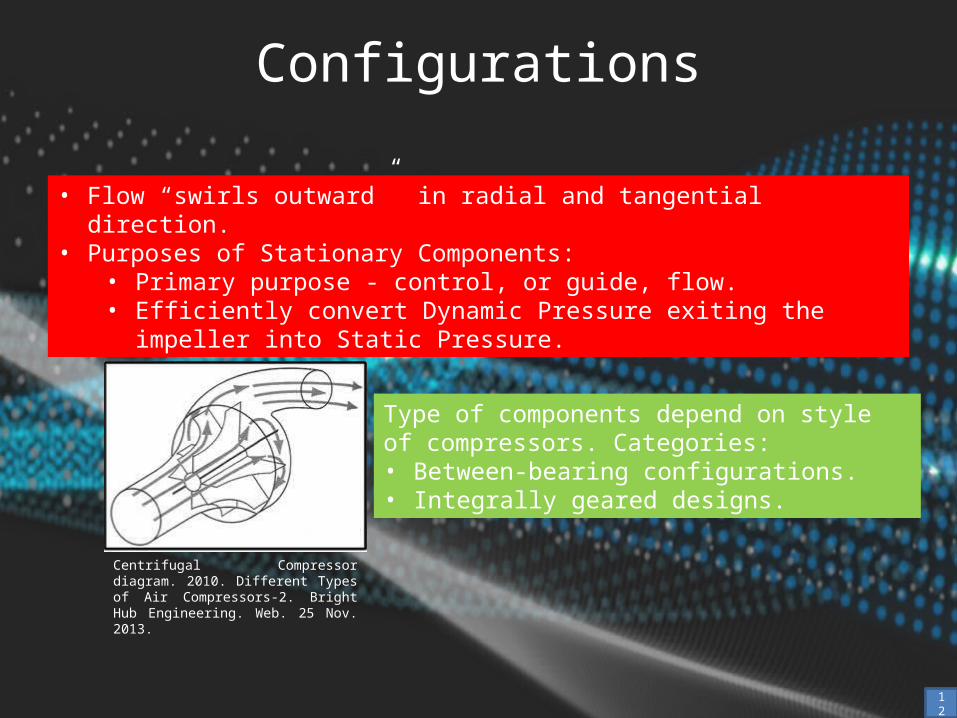
Configurations
• Flow “swirls outward” in radial and tangential direction.• Purposes of Stationary Components:
• Primary purpose - control, or guide, flow.• Efficiently convert Dynamic Pressure exiting the impeller into Static Pressure.
Type of components depend on style of compressors. Categories: • Between-bearing configurations.• Integrally geared designs.
Centrifugal Compressor diagram. 2010. Different Types of Air Compressors-2. Bright Hub Engineering. Web. 25 Nov. 2013.
12
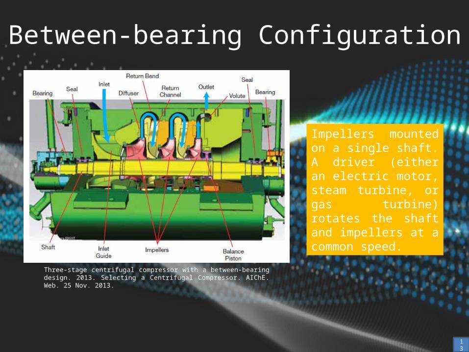
Between-bearing Configuration
Impellers mounted on a single shaft. A driver (either an electric motor, steam turbine, or gas turbine) rotates the shaft and impellers at a common speed.
Three-stage centrifugal compressor with a between-bearing design. 2013. Selecting a Centrifugal Compressor. AIChE. Web. 25 Nov. 2013.
13
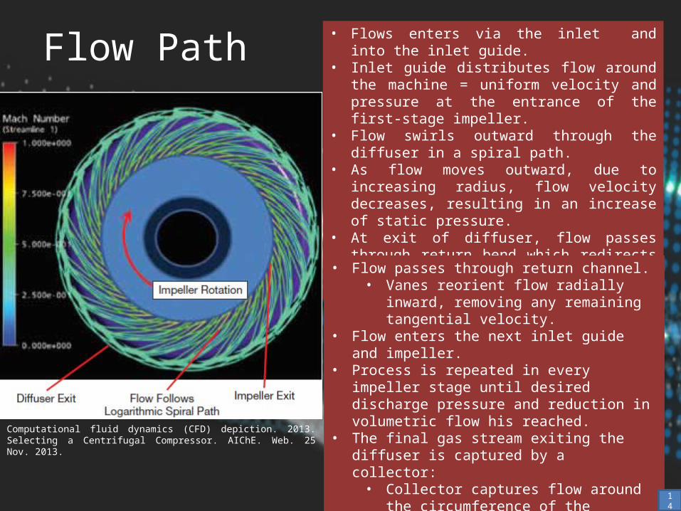
Flow Path
Computational fluid dynamics (CFD) depiction. 2013. Selecting a Centrifugal Compressor. AIChE. Web. 25 Nov. 2013.
• Flows enters via the inlet and into the inlet guide.• Inlet guide distributes flow around the machine =
uniform velocity and pressure at the entrance of the first-stage impeller.
• Flow swirls outward through the diffuser in a spiral path.
• As flow moves outward, due to increasing radius, flow velocity decreases, resulting in an increase of static pressure.
• At exit of diffuser, flow passes through return bend which redirects flow from spiraling radially outward to inward.
• Flow passes through return channel.• Vanes reorient flow radially inward, removing
any remaining tangential velocity.• Flow enters the next inlet guide and impeller.• Process is repeated in every impeller stage until
desired discharge pressure and reduction in volumetric flow his reached.
• The final gas stream exiting the diffuser is captured by a collector:• Collector captures flow around the
circumference of the compressor and guides it into discharge piping.
14
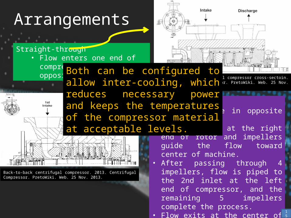
Arrangements
Straight-through centrifugal compressor cross-sectoin. 2013. Centrifugal Compressor. PretoWiki. Web. 25 Nov. 2013.
Straight-through• Flow enters one end of compressor
and exits at opposite end.
Back-to-back centrifugal compressor. 2013. Centrifugal Compressor. PretoWiki. Web. 25 Nov. 2013.
Back-to-back• Impellers face in opposite directions.• Main inlet is at the right end of rotor and
impellers guide the flow toward center of machine.
• After passing through 4 impellers, flow is piped to the 2nd inlet at the left end of compressor, and the remaining 5 impellers complete the process.
• Flow exits at the center of compressor.• Reduces pressure on the shaft end seals.• Used in compressors with high discharge
pressure.
Both can be configured to allow inter-cooling, which reduces necessary power and keeps the temperatures of the compressor material at acceptable levels.
15
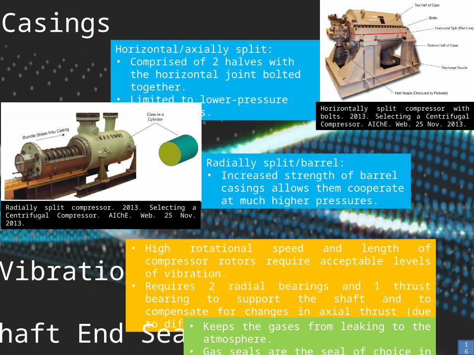
CasingsHorizontal/axially split:• Comprised of 2 halves with the horizontal
joint bolted together.• Limited to lower-pressure applications.
Horizontally split compressor with bolts. 2013. Selecting a Centrifugal Compressor. AIChE. Web. 25 Nov. 2013.
Radially split/barrel:• Increased strength of barrel casings allows
them cooperate at much higher pressures.
Radially split compressor. 2013. Selecting a Centrifugal Compressor. AIChE. Web. 25 Nov. 2013.
Vibration• High rotational speed and length of compressor rotors require
acceptable levels of vibration.• Requires 2 radial bearings and 1 thrust bearing to support the
shaft and to compensate for changes in axial thrust (due to different flow conditions).
Shaft End Seal • Keeps the gases from leaking to the atmosphere.• Gas seals are the seal of choice in most applications.
16
Integrally Geared Designs
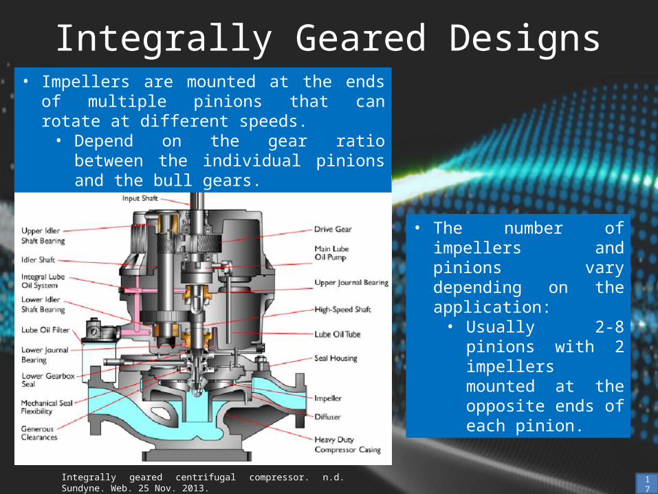
Integrally geared centrifugal compressor. n.d. Sundyne. Web. 25 Nov. 2013.
• Impellers are mounted at the ends of multiple pinions that can rotate at different speeds.• Depend on the gear ratio between the
individual pinions and the bull gears.
• The number of impellers and pinions vary depending on the application:• Usually 2-8 pinions
with 2 impellers mounted at the opposite ends of each pinion.
17
Flow Path
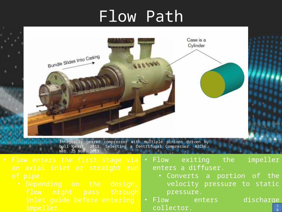
Integrally geared compressor with multiple pinions driven by bull gears. 2013. Selecting a Centrifugal Compressor. AIChE. Web. 25 Nov. 2013.
• Flow enters the first stage via an axial inlet or straight run of pipe.• Depending on the design, flow might
pass through inlet guide before entering impeller.
• Impeller adds kinetic energy to flow stream.
• Flow exiting the impeller enters a diffuser.• Converts a portion of the velocity
pressure to static pressure.• Flow enters discharge collector.• Flow from collector is piped to the axial inlet
of the next stage.18
Differences
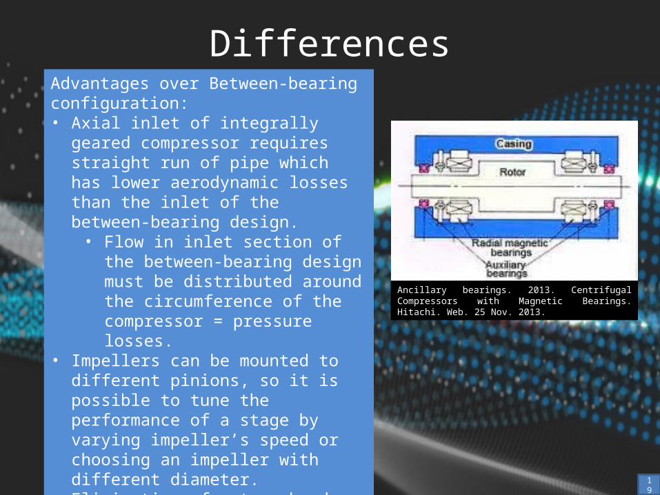
Ancillary bearings. 2013. Centrifugal Compressors with Magnetic Bearings. Hitachi. Web. 25 Nov. 2013.
Advantages over Between-bearing configuration:• Axial inlet of integrally geared compressor
requires straight run of pipe which has lower aerodynamic losses than the inlet of the between-bearing design.• Flow in inlet section of the between-
bearing design must be distributed around the circumference of the compressor = pressure losses.
• Impellers can be mounted to different pinions, so it is possible to tune the performance of a stage by varying impeller’s speed or choosing an impeller with different diameter.
• Elimination of return bend and return channel in the between-bearing design reduces losses, but collector losses are only slightly lower.
19
Differences
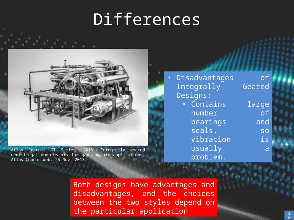
Atlas Copco's GT Series. 2013. Integrally geared centrifugal compressors for gas and air applications. Atlas Copco. Web. 25 Nov. 2013.
• Disadvantages of Integrally Geared Designs:• Contains large number of
bearings and seals, so vibration is usually a problem.
Both designs have advantages and disadvantages, and the choices between the two styles depend on the particular application
20
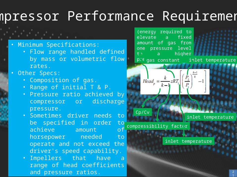
Compressor Performance Requirements
• Minimum Specifications:• Flow range handled defined by mass or
volumetric flow rates.• Other Specs:
• Composition of gas.• Range of initial T & P.• Pressure ratio achieved by compressor
or discharge pressure.• Sometimes driver needs to be
specified in order to achieve amount of horsepower needed to operate and not exceed the driver's speed capability.
• Impellers that have a range of head coefficients and pressure ratios.
(energy required to elevate a fixed amount of gas from one pressure level to a higher pressure level)
Cp/Cv
compressibility factor
gas constant
inlet temperature
inlet temperature
inlet temperature
21
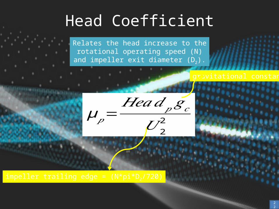
Head CoefficientRelates the head increase to the rotational
operating speed (N) and impeller exit diameter (D2).
gravitational constant
impeller trailing edge = (N*pi*D2/720)
22
μ𝑝=𝐻𝑒𝑎𝑑𝑝𝑔𝑐
𝑈 22
Impeller Performance
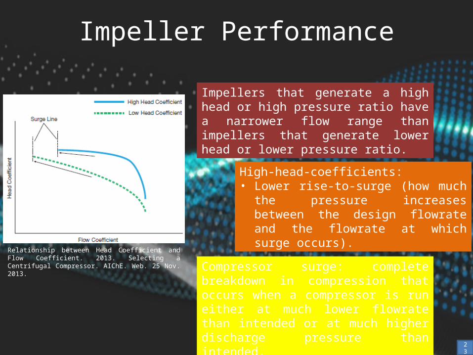
Relationship between Head Coefficient and Flow Coefficient. 2013. Selecting a Centrifugal Compressor. AIChE. Web. 25 Nov. 2013.
Impellers that generate a high head or high pressure ratio have a narrower flow range than impellers that generate lower head or lower pressure ratio.
High-head-coefficients:• Lower rise-to-surge (how much the
pressure increases between the design flowrate and the flowrate at which surge occurs).
Compressor surge: complete breakdown in compression that occurs when a compressor is run either at much lower flowrate than intended or at much higher discharge pressure than intended.
23
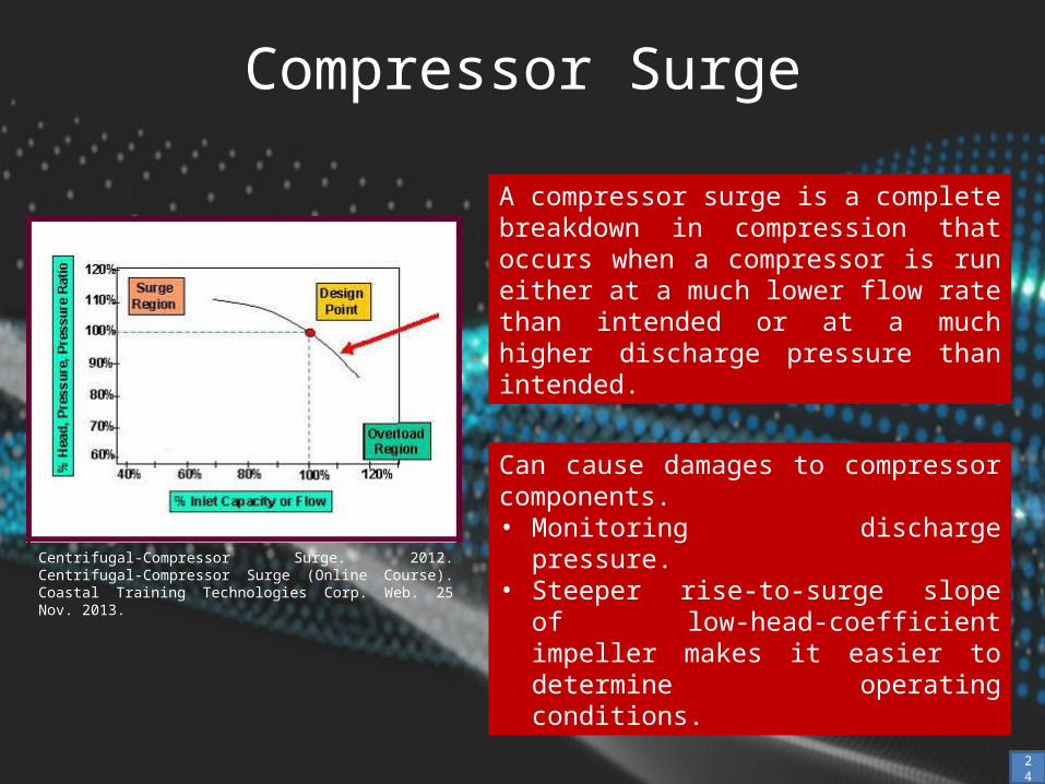
Compressor Surge
Centrifugal-Compressor Surge. 2012. Centrifugal-Compressor Surge (Online Course). Coastal Training Technologies Corp. Web. 25 Nov. 2013.
A compressor surge is a complete breakdown in compression that occurs when a compressor is run either at a much lower flow rate than intended or at a much higher discharge pressure than intended.
Can cause damages to compressor components.• Monitoring discharge pressure.• Steeper rise-to-surge slope of low-head-
coefficient impeller makes it easier to determine operating conditions.
24
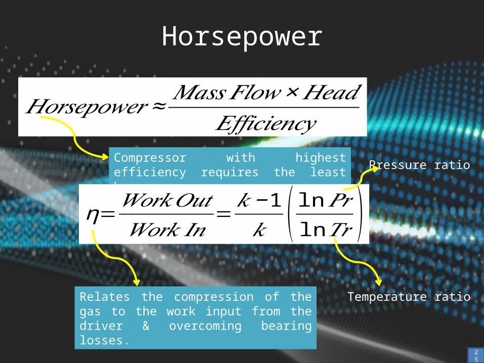
Horsepower
Compressor with highest efficiency requires the least horsepower.
Relates the compression of the gas to the work input from the driver & overcoming bearing losses.
Pressure ratio
Temperature ratio
25
𝐻𝑜𝑟𝑠𝑒𝑝𝑜𝑤𝑒𝑟 ≈𝑀𝑎𝑠𝑠𝐹𝑙𝑜𝑤×𝐻𝑒𝑎𝑑
𝐸𝑓𝑓𝑖𝑐𝑖𝑒𝑛𝑐𝑦
η=𝑊𝑜𝑟𝑘𝑂𝑢𝑡𝑊𝑜𝑟𝑘 𝐼𝑛
=𝑘−1𝑘 ( ln 𝑃𝑟ln𝑇𝑟 )
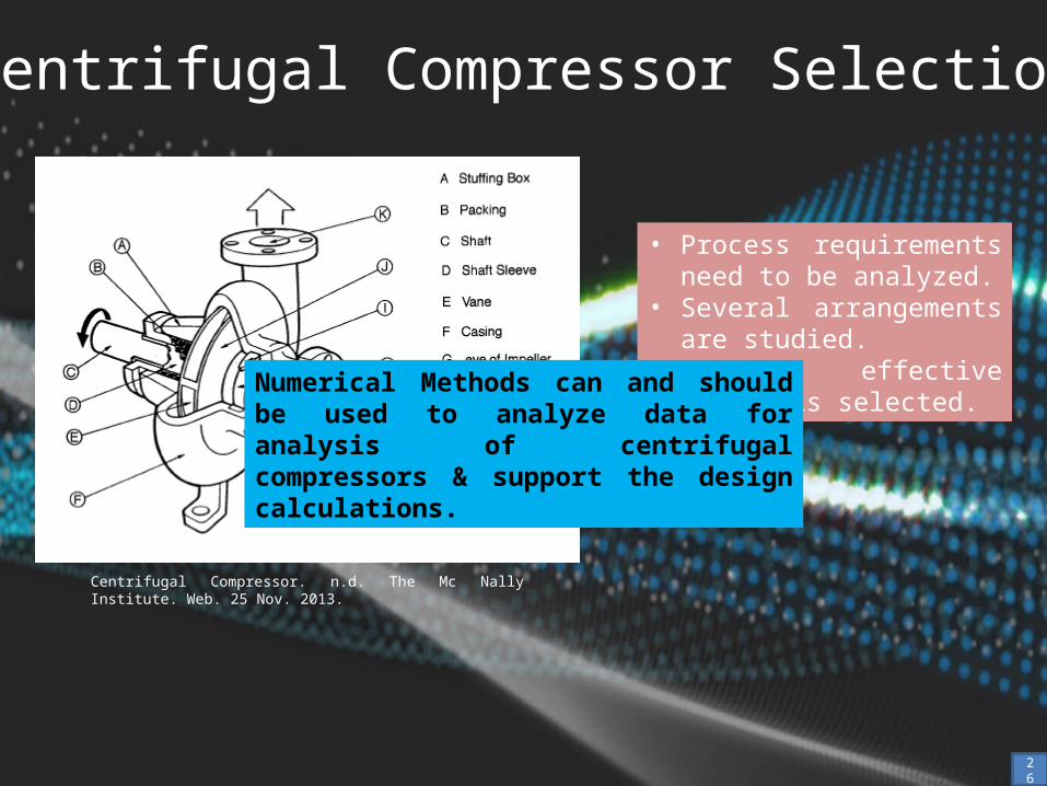
Centrifugal Compressor Selection
Centrifugal Compressor. n.d. The Mc Nally Institute. Web. 25 Nov. 2013.
• Process requirements need to be analyzed.
• Several arrangements are studied.
• Most effective design is selected.
Numerical Methods can and should be used to analyze data for analysis of centrifugal compressors & support the design calculations.
26
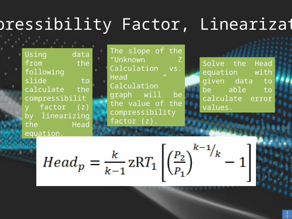
Compressibility Factor, Linearization
Using data from the following slide to calculate the compressibility factor (z) by linearizing the Head equation.
Solve the Head equation with given data to be able to calculate error values.
27
The slope of the “Unknown Z Calculation vs. Head Calculation” graph will be the value of the compressibility factor (z).
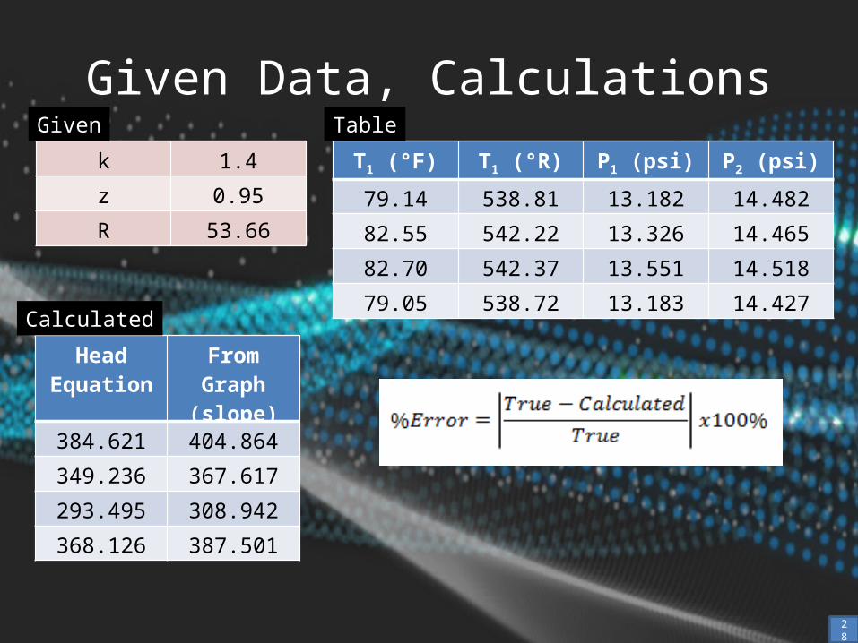
Given Data, Calculations
28
k 1.4
z 0.95
R 53.66
Given
Head Equation
From Graph (slope)
384.621 404.864
349.236 367.617
293.495 308.942
368.126 387.501
Calculated
T1 (°F) T1 (°R) P1 (psi) P2 (psi)
79.14 538.81 13.182 14.482
82.55 542.22 13.326 14.465
82.70 542.37 13.551 14.518
79.05 538.72 13.183 14.427
Table
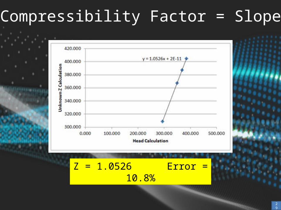
Compressibility Factor = Slope
29
Z = 1.0526 Error = 10.8%
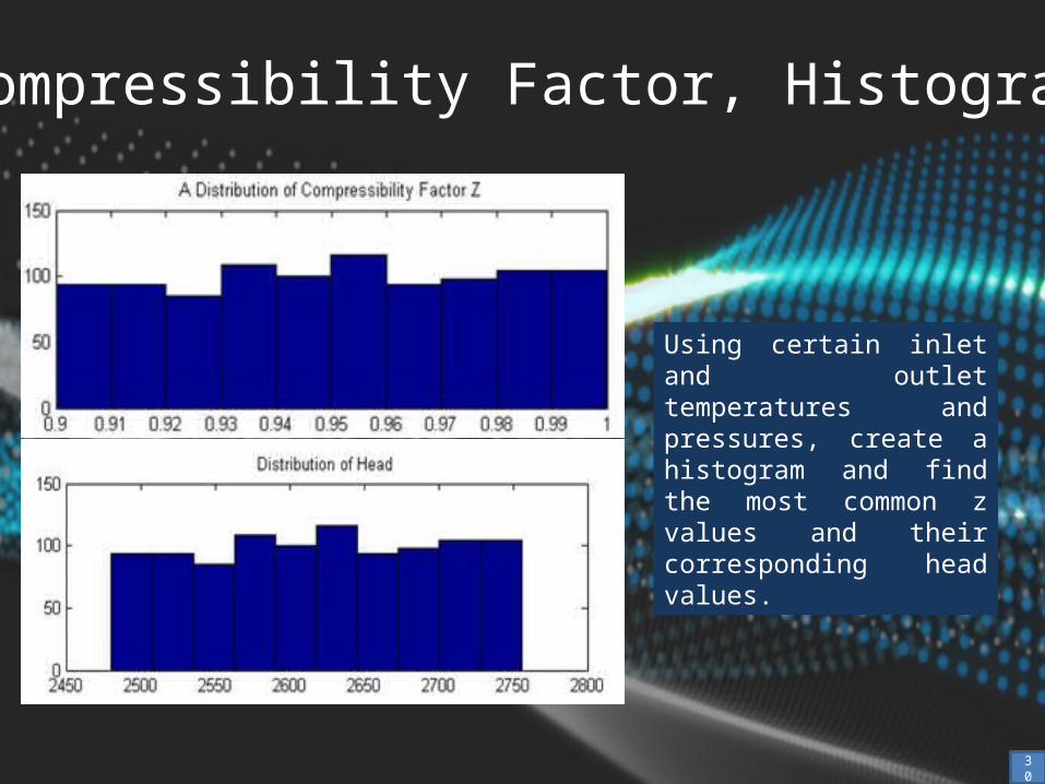
Compressibility Factor, Histogram
Using certain inlet and outlet temperatures and pressures, create a histogram and find the most common z values and their corresponding head values.
30

Matlab Code (Histogram)
format short g% Calculating the Compressibility at an Inlet Pressure of 13.182 psia and an% Outlet Pressure of 14.482 psia, an Inlet Temperature of 538.81R% Generating random z values to see which one most likely fits the data the best.n=1000;k=1.4;R=53.66447;P1=13.182;P2=14.482;T1=538.72;z=0.95;zmin=z-0.05;zmax=z+0.05;r=rand(n,1);zrand=zmin+(zmax-zmin)*r;meanz=mean(zrand),stdz=std(zrand)Deltaz=(max(zrand)-min(zrand))/meanz/2*100;subplot(2,1,1)hist(zrand),title('A Distribution of Compressibility Factor Z')hrand=(k./(k-1)).*zrand.*R.*T1.*((P2/P1).^((k-1)./(k))-1);meanz1=mean(hrand)deltav=(max(hrand)-min(hrand))/meanz1/2*100;subplot(2,1,2)hist(hrand),title('Distribution of Head')
31
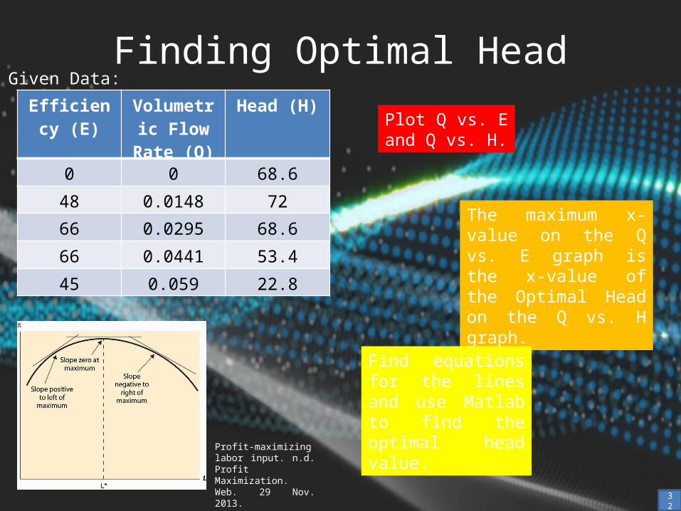
Finding Optimal HeadGiven Data:
Plot Q vs. E and Q vs. H.
The maximum x-value on the Q vs. E graph is the x-value of the Optimal Head on the Q vs. H graph.
Find equations for the lines and use Matlab to find the optimal head value.
32
Efficiency (E) Volumetric Flow Rate
(Q)
Head (H)
0 0 68.6
48 0.0148 72
66 0.0295 68.6
66 0.0441 53.4
45 0.059 22.8
Profit-maximizing labor input. n.d. Profit Maximization. Web. 29 Nov. 2013.
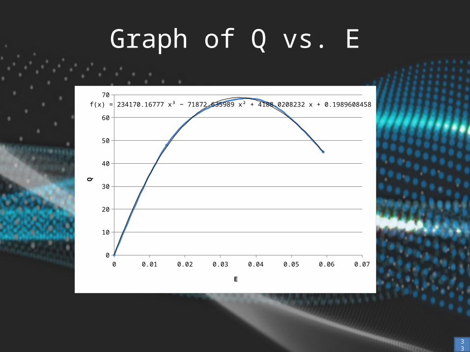
Graph of Q vs. E
33
0 0.01 0.02 0.03 0.04 0.05 0.06 0.070
10
20
30
40
50
60
70f(x) = 234170.167765982 x³ − 71872.6359889223 x² + 4188.02082317859 x + 0.198960845776355
E
Q
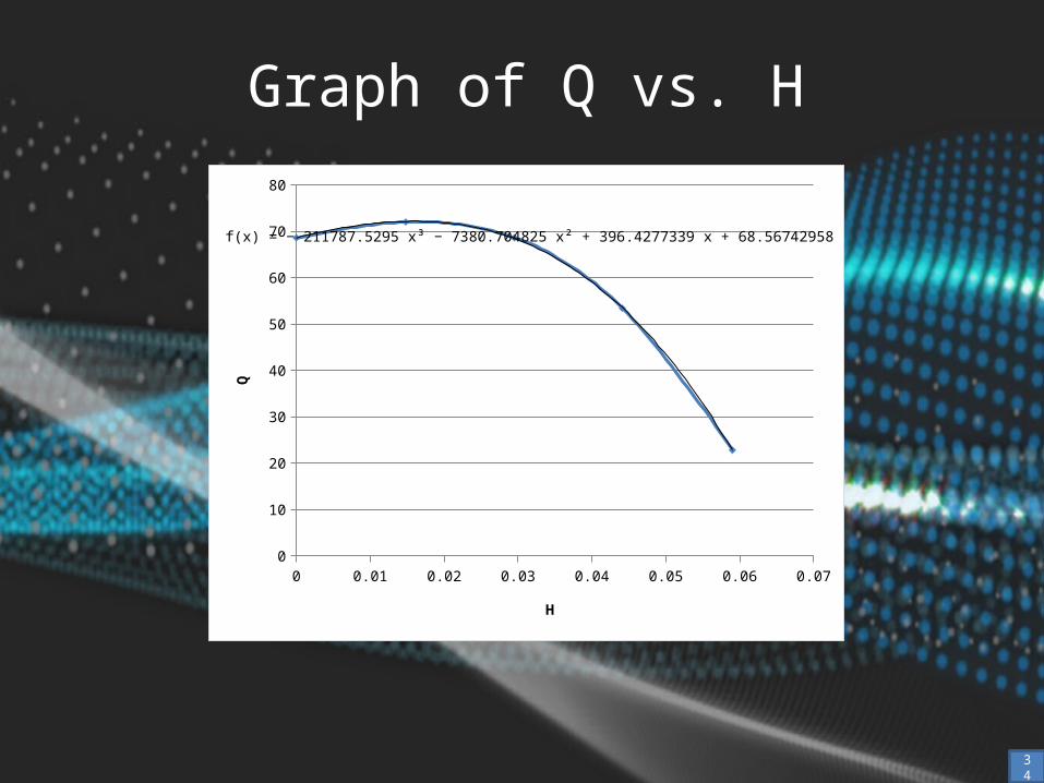
Graph of Q vs. H
34
0 0.01 0.02 0.03 0.04 0.05 0.06 0.070
10
20
30
40
50
60
70
80
f(x) = − 211787.529484086 x³ − 7380.7048248353 x² + 396.427733910661 x + 68.5674295839617
H
Q

Matlab Code (Optimal Head)
>> %Using the polynomial equations based on the chart, find the max value of the Q vs. E, plug in that x value to the Q vs. H equation to find the optimal head.>> syms x>> y = 2342170*x^3 - 71873*x^2 + 4188*x + 0.199;>> D = diff(y)D =
7026510*x^2 - 143746*x + 4188
>> clear>> %The Q vs. E differential equation: dy = 702510*x^2 - 143746*x + 4188>> %To find the max point on the graph, solve for the zeros of the differential equation.>> %An initial guess of the zero will be used, 0.04>>
35
Interpreting the wave equation. n.d. Wave Equations. 29 Nov. 2013.

Matlab Code (Optimal Head)
>> fzero(@(x) 702510*x^2 - 143746*x + 4188, 0.04)
ans =
0.0352>> %The max point on the Q vs. E graph appears when Q = 0.0352>> %Find the corresponding H value to get the optimal head of the centrifugal pump>> %The Q vs. H equation is y = -211788*x^3-7380.7*x^+396.43*x+68.567>> H = -211788*(0.0352)^3-7380.7*(0.0352)^2+396.43*(0.0352)+68.567
H =
64.139436
Maximum. 2008. Quadratic Graph Maximum. Math Junkies. Web. 29 Nov. 2013.

Function FilesTo simplify the process of checking data, .m files of each equation were created in Matlab.
Efficiencyfunction [ Nu ] = efficiency( k, T1, T2, P1, P2 )% Efficiency: relates the actual work done on the gas to the total work% input into the compression system, Efficiency = (Work Out)/(Work In)% k = ratio of specific heats (Cp/Cv)% T1 = inlet temperature% T2 = inlet temperature% P1 = inlet pressure% P2 = discharge pressure% Output% Nu = efficiency
Nu = ((k-1)/k)*((log(P2/P1))/(log(T2/T1)));
end37
>> % Checking Efficiency Code.>> >> efficiency(1.4,100,150,15,16)
ans =
0.0455

Flow coefficient
function [ Phi ] = FlowCoeff( Q, N, D )% Flow Coefficient:relate an impeller's volumetric flow capacity, Q,% operating speed, N, and exit diameter, D% Q = volumetric flow capacity (ft^3/min)% N = operating speed (rpm)% D = exit diameter (ft)%Output% Phi = flow coefficient
Phi = Q/(N*D^3);
end
38
>> % Checking Flow Coefficient Code.>> >> FlowCoeff(1000,50,15)
ans =
0.0059
>>
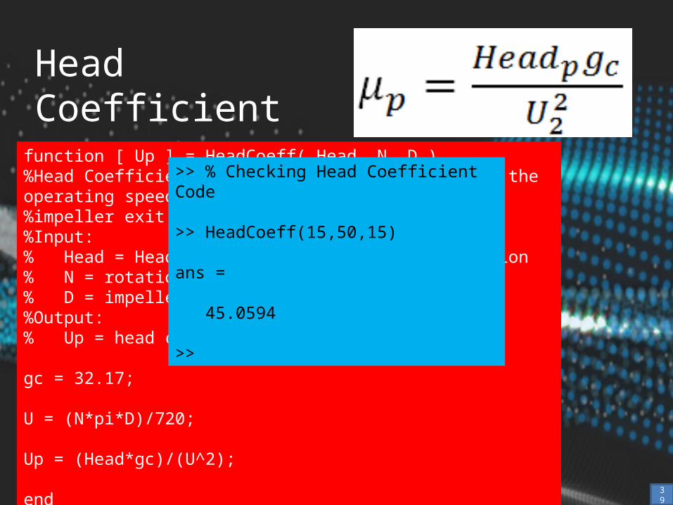
Head Coefficient
function [ Up ] = HeadCoeff( Head, N, D )%Head Coefficient: related the head increase to the operating speed (N) and%impeller exit diameter (D)%Input:% Head = Head calculated using the Head equation% N = rotational speed (rpm)% D = impeller blade exit diameter (in)%Output:% Up = head coefficient
gc = 32.17;
U = (N*pi*D)/720;
Up = (Head*gc)/(U^2);
end39
>> % Checking Head Coefficient Code
>> HeadCoeff(15,50,15)
ans =
45.0594
>>
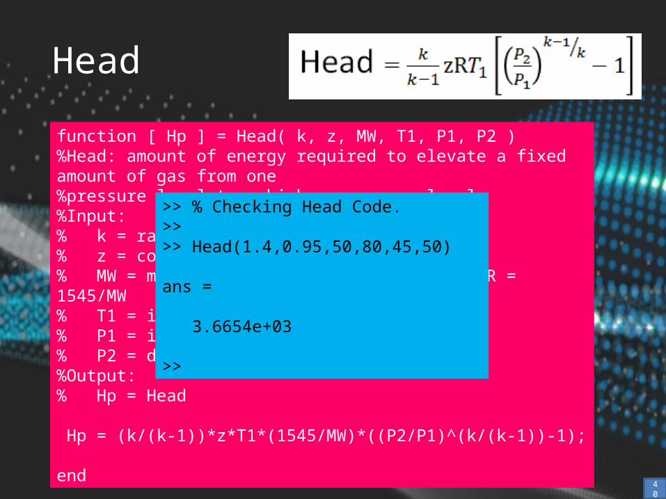
Head
function [ Hp ] = Head( k, z, MW, T1, P1, P2 )%Head: amount of energy required to elevate a fixed amount of gas from one%pressure level to a higher pressure level%Input:% k = ratio of specific heats (Cp/Cv)% z = compressibility factor of the gas% MW = mole weight, used to calculate R, R = 1545/MW% T1 = inlet temperature (degrees R)% P1 = inlet pressure (psia)% P2 = discharge pressure (psia)%Output:% Hp = Head
Hp = (k/(k-1))*z*T1*(1545/MW)*((P2/P1)^(k/(k-1))-1);
end
40
>> % Checking Head Code.>> >> Head(1.4,0.95,50,80,45,50)
ans =
3.6654e+03
>>
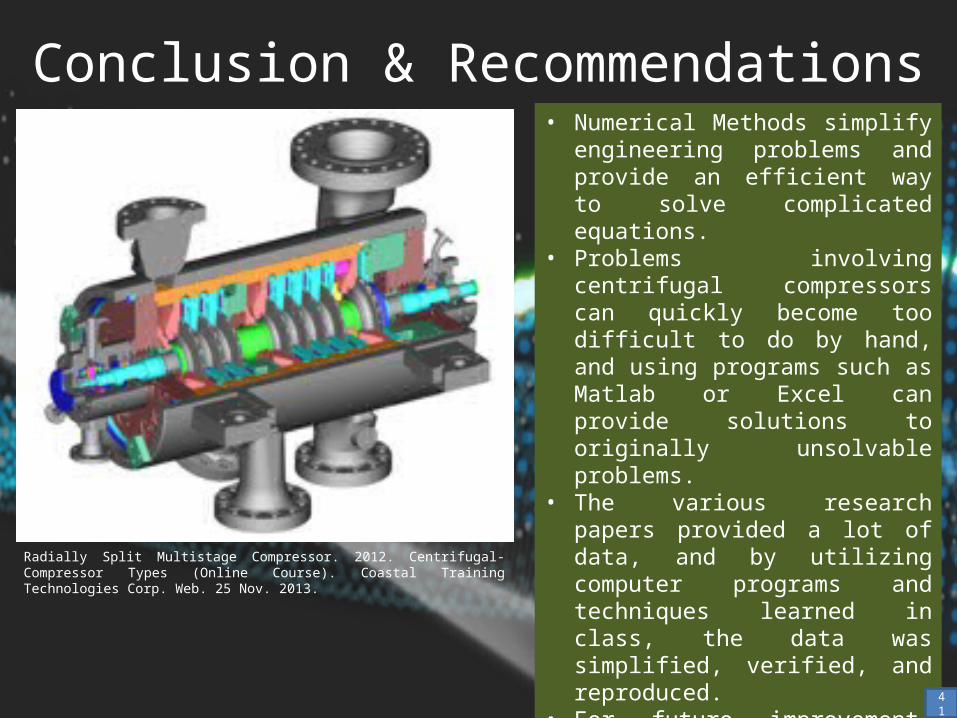
Conclusion & Recommendations
Radially Split Multistage Compressor. 2012. Centrifugal-Compressor Types (Online Course). Coastal Training Technologies Corp. Web. 25 Nov. 2013.
• Numerical Methods simplify engineering problems and provide an efficient way to solve complicated equations.
• Problems involving centrifugal compressors can quickly become too difficult to do by hand, and using programs such as Matlab or Excel can provide solutions to originally unsolvable problems.
• The various research papers provided a lot of data, and by utilizing computer programs and techniques learned in class, the data was simplified, verified, and reproduced.
• For future improvement, researchers using Centrifugal Compressors should have a standardized method of recording and presenting data in order to verify known equations.
41
References• Sorokes, James M. "Selecting a Centrifugal Compressor." AIChE, June 2013. Web. 17 Nov. 2013.• Dunn, D. J. "Fluid Mechanics Tutorial No. 8B." FreeStudy, n.d. Web. 17 Nov. 2013.• Shah, Shreekant, and John Bartos. "Confirming Centrifugal Compressor Aerodynamic Performance Using Limited Test Data Combined With Computational Fluid Dynamic
Techniques." Web. 17 Nov. 2013.• Moore, J. J., Augusto Garcia-Hernandez, Matthew Blieske, Rainer Kurz, and Klaus Brun. "Transient Surge Measurements of a Centrifugal Compressor Station During
Emergency Shutdowns." Web. 17 Nov. 2013.• Abouteeet. ”CENTRIFUGAL COMPRESSORNPOS.AVI.” Online video clip. YouTube. Youtube, 16 Apr. 2010. Web. 25 Nov. 2013. • Efficient frictionless centrifugal compressor. 2011. Centrifugal Compressor Central Chillers. Thermal Care. Web. 25 Nov. 2013.
<http://www.thermalcare.com/central-chillers/tc-series-central-chillers.php>• Centrifugal compressor multistage axial type. 2009. Oil Free Air. Pneumotech Inc. Web. 25 Nov. 2013.
<http://www.pneumotech.net/oil_free.htm>• Turbocharger. 2012. Want to increase engine power & efficiency apply turbocharger. Innovatize. Web. 25 Nov. 2013.
<http://innovatize.blogspot.com/2012/01/want-to-increase-engine-power.html>• BCL Series Centrifugal Compressor. 2009. BCL-Vertical Split Casing Series. V-FLO Group of Companies. Web. 25 Nov. 2013.
<http://www.v-flo.com/Products/GoodShow-188.aspx>• Single Shaft and Overhung Centrifugal Compressors. Kobelco. Web. 28 Nov. 2013.
<http://kobelcocompressors.com/index.php/single_shaft_and_overhung_centrifugal_compressors/>• How Does A Centrifugal Compressor Work? 2013. Inside the DATUM Compressor. Dresse-Rand. Web. 25 Nov. 2013.
<http://datum.dresser-rand.com/inside-the-datum-compressor.php>• Centrifugal Compressor. 2013. Compressors. Wiki-ref. Web. 25 Nov. 2013.
<http://www.ref-wiki.com/technical-information/145-compressors/31774-compressors.html>• Partial view of the AM01's motor bucket, showing the unshrouded impeller, vaneless diffuser and vaned diffuser. 2011. Concepts NREC software blows holes in
conventional fan design. Desktop Engineering. Web. 25 Nov. 2013.<http://www.deskeng.com/articles/aabbmk.htm>
• Shrouded impeller. n.d. Impeller/Blisks. Prawest. Web. 25 Nov. 2013.<http://www.praewest.com/impeller_blisks.html>
• Centrifugal Compressor diagram. 2010. Different Types of Air Compressors-2. Bright Hub Engineering. Web. 25 Nov. 2013.<http://www.brighthubengineering.com/hvac/65033-different-types-of-air-compressors-part-two/#imgn_0>
• Straight-through centrifugal compressor cross-sectoin. 2013. Centrifugal Compressor. PretoWiki. Web. 25 Nov. 2013.<http://petrowiki.org/Centrifugal_compressor>
• Back-to-back centrifugal compressor. 2013. Centrifugal Compressor. PretoWiki. Web. 25 Nov. 2013.<http://petrowiki.org/Centrifugal_compressor>
• Integrally geared centrifugal compressor. n.d. Sundyne. Web. 25 Nov. 2013.<link not available>
42

• Ancillary bearings. 2013. Centrifugal Compressors with Magnetic Bearings. Hitachi. Web. 25 Nov. 2013.<http://www.hitachi-pt.com/products/si/compressor/radial/magnetic.html>
• Atlas Copco's GT Series. 2013. Integrally geared centrifugal compressors for gas and air applications. Atlas Copco. Web. 25 Nov. 2013.<http://www.atlascopco.us/usus/products/Product.aspx?id=1521439&productgroupid=1401256>
• Centrifugal-Compressor Surge. 2012. Centrifugal-Compressor Surge (Online Course). Coastal Training Technologies Corp. Web. 25 Nov. 2013.<http://ecom.training.dupont.com/TWB002-INT-ENG(CoastalU)/IS(Dresser-Rand%C2%AE)/en-US/ProductDetails_us/Centrifugal8211Compressor-training.aspx>
• Centrifugal Compressor. n.d. The Mc Nally Institute. Web. 25 Nov. 2013.<http://www.pumpfundamentals.com/pump_glossary.htm.>
• Radially Split Multistage Compressor. 2012. Centrifugal-Compressor Types (Online Course). Coastal Training Technologies Corp. Web. 25 Nov. 2013.<http://ecom.training.dupont.com/TWB001-INT-ENG(CoastalU)/IS(Dresser-Rand%C2%AE)/en-US/ProductDetails_us/Centrifugal8211Compressor-training.aspx>
• Interpreting the wave equation. n.d. Wave Equations. 29 Nov. 2013.<http://electron6.phys.utk.edu/phys250/modules/module%202/wave_equations.htm>
• Maximum. 2008. Quadratic Graph Maximum. Math Junkies. Web. 29 Nov. 2013.<http://www.mathjunkies.com/DesktopModules/Definition/tabid/98/Default.aspx?id=180&val=Quadratic%20Graph%20Maximum&level=2>
• Profit-maximizing labor input. n.d. Profit Maximization. Web. 29 Nov. 2013.<http://www.web-books.com/eLibrary/NC/B0/B59/050MB59.html>
References
43


