
Dharmapuri – 636 703
Regulation : 2013
Branch : B.E. – CSE.
Year & Semester : II Year / IV Semester
ICAL EN
CS 6412 - MICROPROCESSOR AND MICROCONTROLLERLABORATORY
LAB MANUAL
CS6412- MICROPROCESSOR AND MICROCONTROLLER LABORATORY 2
VVIT DEPARTMENT OF ELECTRONICS AND COMMUNICATION ENGINEERING
ANNA UNIVERSITY CHENNAI
Regulation 2013
CS6412- MICROPROCESSOR AND MICROCONTROLLER LABORATORY
SYLLABUS
LIST OF EXPERIMENTS:
8086 Programs using kits and MASM
1. Basic arithmetic and Logical operations
2. Move a data block without overlap
3. Code conversion, decimal arithmetic and Matrix operations.
4. Floating point operations, string manipulations, sorting and searching
5. Password checking, Print RAM size and system date
6. Counters and Time Delay
Peripherals and Interfacing Experiments
7. Traffic light control
8. Stepper motor control
9. Digital clock
10.Key board and Display
11.Printer status
12.Serial interface and Parallel interface
13.A/D and D/A interface and Waveform Generation 8051.
Experiments using kits and MASM
14. Basic arithmetic and Logical operations
15. Square and Cube program, Find 2’s complement of a number
16. Unpacked BCD to ASCII
TOTAL: 45 PERIODS
CS6412- MICROPROCESSOR AND MICROCONTROLLER LABORATORY 3
VVIT DEPARTMENT OF ELECTRONICS AND COMMUNICATION ENGINEERING
INTRODUCTION TO MICROPROCESSORS & MICROCONTROLLERS:
Microprocessor and controller is digital and programmable device with highlyreliable and secured modern architecture. Building blocks of the Digital computerCPU functions Memory types Input / Output Devices Stored program concept Historyof Microprocessors.
Intel 8085 microprocessor:
Internal architecture, Hardware description, Interrupts and interrupts servicingand Interfacing the memory. Assembly Language Programming: 8085- Addressingmodes & Instruction set, Flow charts, Assembly language programming andassembler directives, Linker and its operation, Programming examples.
Interfacing the input / output devices:
8255 Programmable Peripheral Interface, i8253 Programmable Interval Timer,8251 Universal Synchronous /Asynchronous Receiver Transmitter, 8259Programmable Interrupt Controller and i8279 Programmable Keyboard / Displayinterface device.
Interfacing the data converters:
Digital-to-Analog Converters, Interfacing DAC with 8086 microprocessor,Analog-to-Digital Converters Interfacing ADC with 8086.
Microprocessors:
Intel 8086 family microprocessors, Programming model, Memory paging,Virtual memory concept, advanced features of 80386/486/Pentium Processors.
Microcontroller:
Introduction to Microcontrollers, Intel-8051: Architecture, Hardwaredescription, Memory organization, Addressing Modes.
Programming the i8051:
Instruction set, Assembly language programming, Interrupt structure andinterrupt priorities, Interfacing with external devices and Programming.
CS6412- MICROPROCESSOR AND MICROCONTROLLER LABORATORY 4
VVIT DEPARTMENT OF ELECTRONICS AND COMMUNICATION ENGINEERING
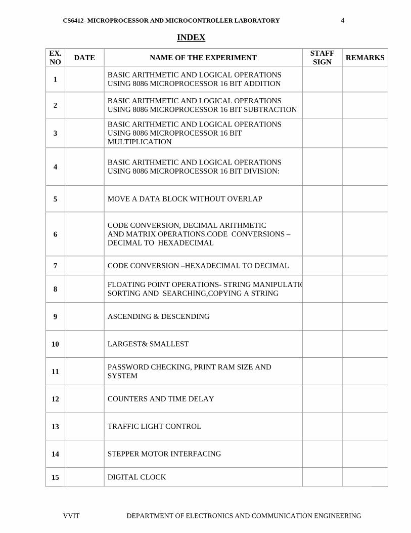
INDEX
EX.NO DATE NAME OF THE EXPERIMENT
STAFFSIGN REMARKS
1BASIC ARITHMETIC AND LOGICAL OPERATIONSUSING 8086 MICROPROCESSOR 16 BIT ADDITION
2BASIC ARITHMETIC AND LOGICAL OPERATIONSUSING 8086 MICROPROCESSOR 16 BIT SUBTRACTION
3BASIC ARITHMETIC AND LOGICAL OPERATIONSUSING 8086 MICROPROCESSOR 16 BITMULTIPLICATION
4BASIC ARITHMETIC AND LOGICAL OPERATIONSUSING 8086 MICROPROCESSOR 16 BIT DIVISION:
5 MOVE A DATA BLOCK WITHOUT OVERLAP
6CODE CONVERSION, DECIMAL ARITHMETICAND MATRIX OPERATIONS.CODE CONVERSIONS –DECIMAL TO HEXADECIMAL
7 CODE CONVERSION –HEXADECIMAL TO DECIMAL
8FLOATING POINT OPERATIONS- STRING MANIPULATIONS,SORTING AND SEARCHING,COPYING A STRING
9 ASCENDING & DESCENDING
10 LARGEST& SMALLEST
11PASSWORD CHECKING, PRINT RAM SIZE ANDSYSTEM
12 COUNTERS AND TIME DELAY
13 TRAFFIC LIGHT CONTROL
14 STEPPER MOTOR INTERFACING
15 DIGITAL CLOCK
CS6412- MICROPROCESSOR AND MICROCONTROLLER LABORATORY 5
VVIT DEPARTMENT OF ELECTRONICS AND COMMUNICATION ENGINEERING
EX.NO DATE NAME OF THE EXPERIMENT
STAFFSIGN REMARKS
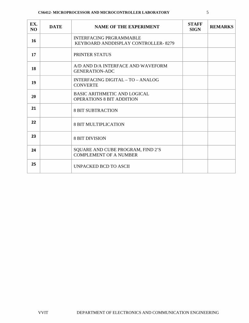
16INTERFACING PRGRAMMABLEKEYBOARD ANDDISPLAY CONTROLLER- 8279
17 PRINTER STATUS
18A/D AND D/A INTERFACE AND WAVEFORMGENERATION-ADC
19INTERFACING DIGITAL – TO – ANALOGCONVERTE
20BASIC ARITHMETIC AND LOGICALOPERATIONS 8 BIT ADDITION
21 8 BIT SUBTRACTION
22 8 BIT MULTIPLICATION
23 8 BIT DIVISION
24 SQUARE AND CUBE PROGRAM, FIND 2’SCOMPLEMENT OF A NUMBER
25 UNPACKED BCD TO ASCII
CS6412- MICROPROCESSOR AND MICROCONTROLLER LABORATORY 6
VVIT DEPARTMENT OF ELECTRONICS AND COMMUNICATION ENGINEERING
EX. NO: 01
DATE :
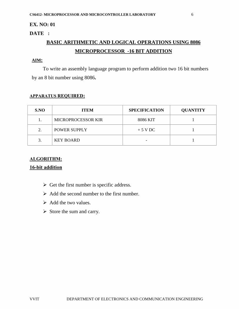
BASIC ARITHMETIC AND LOGICAL OPERATIONS USING 8086
MICROPROCESSOR -16 BIT ADDITION
AIM:
To write an assembly language program to perform addition two 16 bit numbers
by an 8 bit number using 8086.
APPARATUS REQUIRED:
S.NO ITEM SPECIFICATION QUANTITY
1. MICROPROCESSOR KIR 8086 KIT 1
2. POWER SUPPLY + 5 V DC 1
3. KEY BOARD - 1
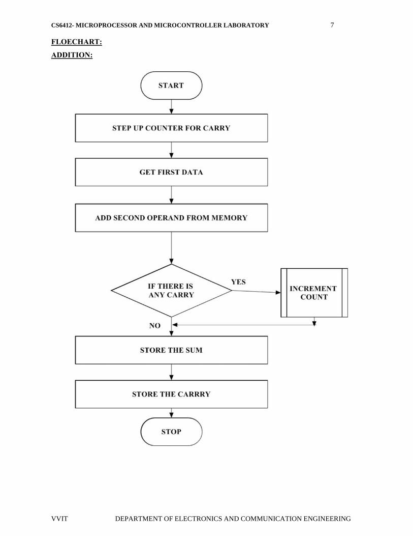
ALGORITHM:
16-bit addition
Get the first number is specific address.
Add the second number to the first number.
Add the two values.
Store the sum and carry.
CS6412- MICROPROCESSOR AND MICROCONTROLLER LABORATORY 7
VVIT DEPARTMENT OF ELECTRONICS AND COMMUNICATION ENGINEERING
FLOECHART:
ADDITION:
CS6412- MICROPROCESSOR AND MICROCONTROLLER LABORATORY 8
VVIT DEPARTMENT OF ELECTRONICS AND COMMUNICATION ENGINEERING
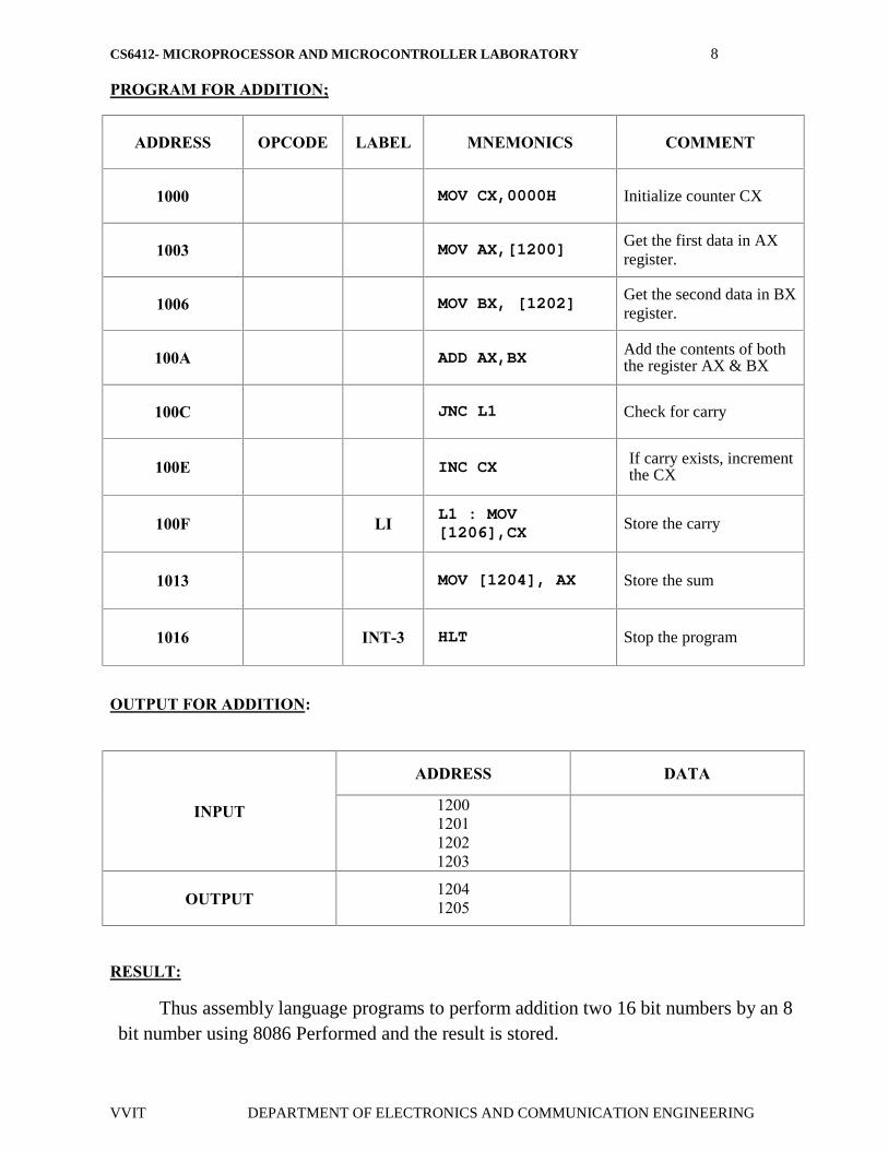
PROGRAM FOR ADDITION;
ADDRESS OPCODE LABEL MNEMONICS COMMENT
1000 MOV CX,0000H Initialize counter CX
1003 MOV AX,[1200] Get the first data in AXregister.
1006 MOV BX, [1202]Get the second data in BXregister.
100A ADD AX,BX Add the contents of boththe register AX & BX
100C JNC L1 Check for carry
100E INC CX If carry exists, incrementthe CX
100F LI L1 : MOV[1206],CX Store the carry
1013 MOV [1204], AX Store the sum
1016 INT-3 HLT Stop the program
OUTPUT FOR ADDITION:
INPUT
ADDRESS DATA
1200120112021203
OUTPUT 12041205
RESULT:
Thus assembly language programs to perform addition two 16 bit numbers by an 8bit number using 8086 Performed and the result is stored.

CS6412- MICROPROCESSOR AND MICROCONTROLLER LABORATORY 9
VVIT DEPARTMENT OF ELECTRONICS AND COMMUNICATION ENGINEERING
EX. NO: 02
DATE :
BASIC ARITHMETIC AND LOGICAL OPERATIONS USING
8086 MICROPROCESSOR - 16 BIT SUBTRACTION
AIM:
To write an assembly language program to perform subtraction two 16 bitnumbers by an 8 bit number using 8086.
APPARATUS REQUIRED:
S.NO ITEM SPECIFICATION QUANTITY
1. MICROPROCESSOR KIR 8086 KIT 1
2. POWER SUPPLY + 5 V DC 1
3. KEY BOARD - 1
ALGORITHM:
16-bit SUBTRACTION:
Initialize the MSBs of difference to 0
Get the first number
Subtract the second number from the first number.
If there is any borrow, increment MSBs of difference by 1.
Store LSBs of difference.
Store MSBs of difference.

CS6412- MICROPROCESSOR AND MICROCONTROLLER LABORATORY 10
VVIT DEPARTMENT OF ELECTRONICS AND COMMUNICATION ENGINEERING
FLOECHART:
SUBTRACTION:
CS6412- MICROPROCESSOR AND MICROCONTROLLER LABORATORY 11
VVIT DEPARTMENT OF ELECTRONICS AND COMMUNICATION ENGINEERING
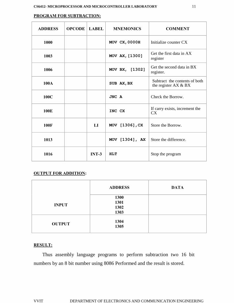
PROGRAM FOR SUBTRACTION:
ADDRESS OPCODE LABEL MNEMONICS COMMENT
1000 MOV CX,0000H Initialize counter CX
1003 MOV AX,[1300] Get the first data in AXregister
1006 MOV BX, [1302] Get the second data in BXregister.
100A SUB AX,BX Subtract the contents of boththe register AX & BX
100C JNC A Check the Borrow.
100E INC CX If carry exists, increment theCX
100F LI MOV [1306],CX Store the Borrow.
1013 MOV [1304], AX Store the difference.
1016 INT-3 HLT Stop the program
OUTPUT FOR ADDITION:
INPUT
ADDRESS DATA
1300130113021303
OUTPUT 13041305
RESULT:
Thus assembly language programs to perform subtraction two 16 bit
numbers by an 8 bit number using 8086 Performed and the result is stored.
CS6412- MICROPROCESSOR AND MICROCONTROLLER LABORATORY 12
VVIT DEPARTMENT OF ELECTRONICS AND COMMUNICATION ENGINEERING
EX. NO: 03
DATE :
BASIC ARITHMETIC AND LOGICAL OPERATIONS USING
8086 MICROPROCESSOR - 16 BIT MULTIPLICATION
AIM:
To write an assembly language program to perform Multiplication two 16 bit
numbers by an 8 bit number using 8086.
APPARATUS REQUIRED:
S.NO ITEM SPECIFICATION QUANTITY
1. MICROPROCESSOR KIR 8086 KIT 1
2. POWER SUPPLY + 5 V DC 1
3. KEY BOARD - 1
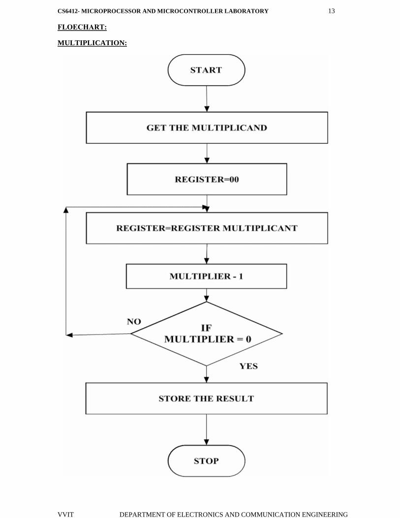
ALGORITHM:
16-bit MULTIPLICATION
Multiplication of 16-bit numbers:
Get the multiplier.
Get the multiplicand
Initialize the product to 0.
Product = product + multiplicand
Decrement the multiplier by 1.
If multiplicand is not equal to 0, repeat from step (d) otherwise store the
product.
CS6412- MICROPROCESSOR AND MICROCONTROLLER LABORATORY 13
VVIT DEPARTMENT OF ELECTRONICS AND COMMUNICATION ENGINEERING
FLOECHART:
MULTIPLICATION:
CS6412- MICROPROCESSOR AND MICROCONTROLLER LABORATORY 14
VVIT DEPARTMENT OF ELECTRONICS AND COMMUNICATION ENGINEERING
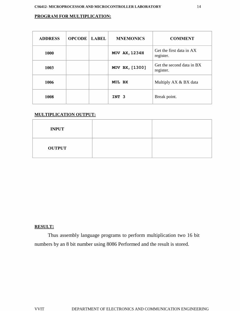
PROGRAM FOR MULTIPLICATION:
ADDRESS OPCODE LABEL MNEMONICS COMMENT
1000 MOV AX,1234H Get the first data in AXregister.
1003 MOV BX,[1300]Get the second data in BXregister.
1006 MUL BX Multiply AX & BX data
1008 INT 3 Break point.
MULTIPLICATION OUTPUT:
INPUT
OUTPUT
RESULT:
Thus assembly language programs to perform multiplication two 16 bit
numbers by an 8 bit number using 8086 Performed and the result is stored.
CS6412- MICROPROCESSOR AND MICROCONTROLLER LABORATORY 15
VVIT DEPARTMENT OF ELECTRONICS AND COMMUNICATION ENGINEERING
EX. NO: 04
DATE :
BASIC ARITHMETIC AND LOGICAL OPERATIONS USING
8086 MICROPROCESSOR - 16 BIT DIVISION:
AIM:
To write an assembly language program to perform division two 16 bit
numbers by an 8 bit number using 8086.
APPARATUS REQUIRED:
S.NO ITEM SPECIFICATION QUANTITY
1. MICROPROCESSOR KIT 8086 KIT 1
2. POWER SUPPLY + 5 V DC 1
3. KEY BOARD - 1
ALGORITHM:
16-bit division
Division of 16-bit numbers:
Get the dividend and divisor.
Initialize the quotient to 0.
Dividend = dividend–divisor
If the divisor is greater, store the quotient
Go to step 3
If dividend is greater, quotient = quotient+ repeat from step 4.
CS6412- MICROPROCESSOR AND MICROCONTROLLER LABORATORY 16
VVIT DEPARTMENT OF ELECTRONICS AND COMMUNICATION ENGINEERING
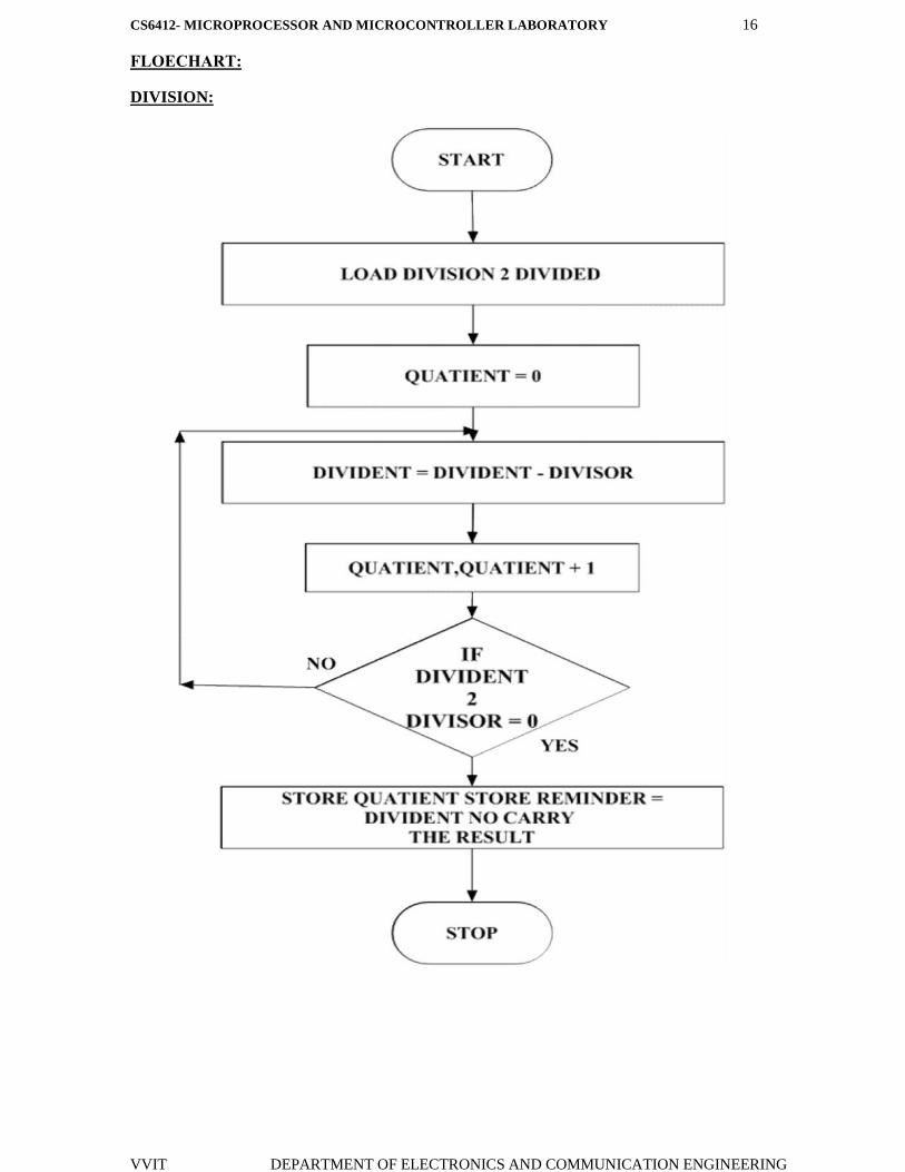
FLOECHART:
DIVISION:
CS6412- MICROPROCESSOR AND MICROCONTROLLER LABORATORY 17
VVIT DEPARTMENT OF ELECTRONICS AND COMMUNICATION ENGINEERING
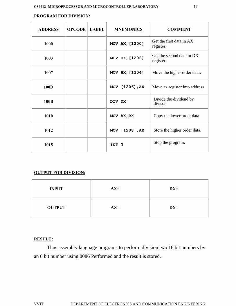
PROGRAM FOR DIVISION:
ADDRESS OPCODE LABEL MNEMONICS COMMENT
1000 MOV AX,[1200]Get the first data in AXregister,
1003 MOV DX,[1202] Get the second data in DXregister.
1007 MOV BX,[1204] Move the higher order data.
100D MOV [1206],AX Move ax register into address
100B DIV DX Divide the dividend bydivisor
1010 MOV AX,BX Copy the lower order data
1012 MOV [1208],AX Store the higher order data.
1015 INT 3 Stop the program.
OUTPUT FOR DIVISION:
INPUT AX= DX=
OUTPUT AX= DX=
RESULT:
Thus assembly language programs to perform division two 16 bit numbers by
an 8 bit number using 8086 Performed and the result is stored.
CS6412- MICROPROCESSOR AND MICROCONTROLLER LABORATORY 18
VVIT DEPARTMENT OF ELECTRONICS AND COMMUNICATION ENGINEERING
EX. NO: 05
DATE :
MOVE A DATA BLOCK WITHOUT OVERLAP
AIM:
To move a data block without overlap
APPARATUS REQUIRED:
S.NO ITEM SPECIFICATION QUANTITY
1. MICROPROCESSOR KIR 8086 KIT 1
2. POWER SUPPLY + 5 V DC 1
3. KEY BOARD - 1
ALGORITHM:
Initialize the memory location to the data pointer.
Increment B register.
Increment accumulator by 1 and adjust it to decimal every time.
Compare the given decimal number with accumulator value.
When both match, the equivalent hexadecimal value is in B register.
Store the resultant in memory location.
CS6412- MICROPROCESSOR AND MICROCONTROLLER LABORATORY 19
VVIT DEPARTMENT OF ELECTRONICS AND COMMUNICATION ENGINEERING
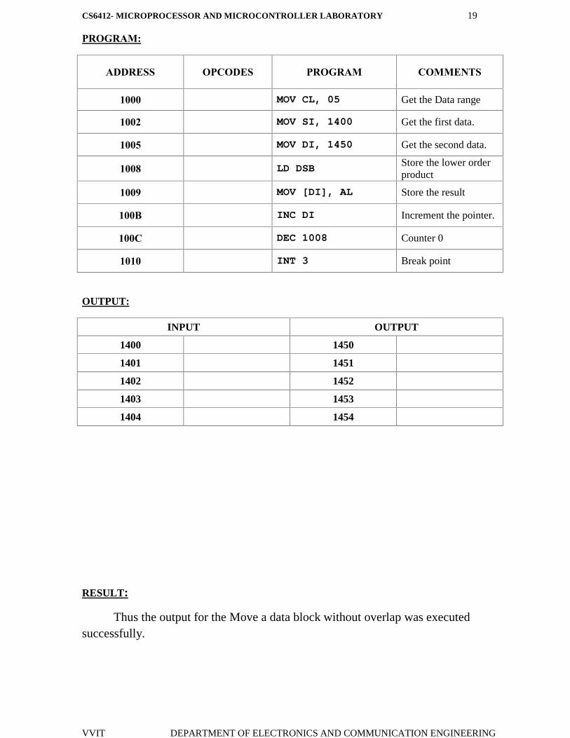
PROGRAM:
ADDRESS OPCODES PROGRAM COMMENTS
1000 MOV CL, 05 Get the Data range
1002 MOV SI, 1400 Get the first data.
1005 MOV DI, 1450 Get the second data.
1008 LD DSB Store the lower orderproduct
1009 MOV [DI], AL Store the result
100B INC DI Increment the pointer.
100C DEC 1008 Counter 0
1010 INT 3 Break point
OUTPUT:
INPUT OUTPUT
1400 1450
1401 1451
1402 1452
1403 1453
1404 1454
RESULT:
Thus the output for the Move a data block without overlap was executedsuccessfully.
CS6412- MICROPROCESSOR AND MICROCONTROLLER LABORATORY 20
VVIT DEPARTMENT OF ELECTRONICS AND COMMUNICATION ENGINEERING
EX. NO: 06
DATE :
CODE CONVERSION, DECIMAL ARITHMETIC
AND MATRIX OPERATIONS.
Code Conversions –Decimal to Hexadecimal:
AIM:
To convert a given decimal number to hexadecimal.
ALGORITHM:
Initialize the memory location to the data pointer.
Increment B register.
Increment accumulator by 1 and adjust it to decimal every time.
Compare the given decimal number with accumulator value.
When both match, the equivalent hexadecimal value is in B register.
Store the resultant in memory location.
CS6412- MICROPROCESSOR AND MICROCONTROLLER LABORATORY 21
VVIT DEPARTMENT OF ELECTRONICS AND COMMUNICATION ENGINEERING
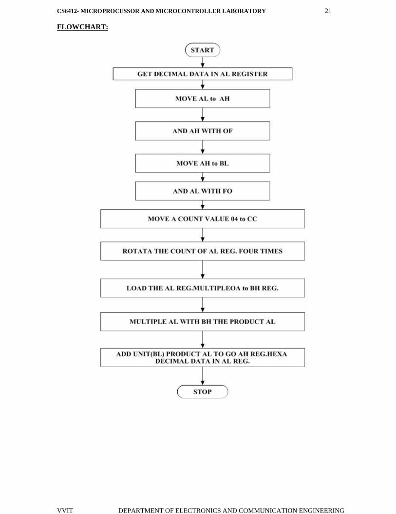
FLOWCHART:

CS6412- MICROPROCESSOR AND MICROCONTROLLER LABORATORY 22
VVIT DEPARTMENT OF ELECTRONICS AND COMMUNICATION ENGINEERING
PROGRAM:
ADDRESS OPCODE LABEL MNEMONICS COMMENDS
1000 MOV AL, [1100] Move data block AL
1003 MOV AH, AL Move data lower to higher
1005 MOV AH, OF Move data OF into AH
1008 MOV BL, AH Move data BL into AH
100A AND AL, FO AND the data AL to FO
100C MOV CL, 04 Move data 04 to CL block
100E ROR AL, CL Rotate functions CL and AL
1010 MOV BH, OA Move data OA into BH
1012 MUL BH Multiply BH
1014 ADD AL, BL ADD the data AL And BL
1016 MOV [2000], AL Move the store data
1019 INT-3 Halt program
OUTPUT:[DECIMAL TO HEXADECIMAL]
DATA ADRESS DATA
INPUT
OUTPUT
RESULT:
Thus the output for the code conversions –decimal to hex was executed
successfully.
CS6412- MICROPROCESSOR AND MICROCONTROLLER LABORATORY 23
VVIT DEPARTMENT OF ELECTRONICS AND COMMUNICATION ENGINEERING
EX. NO: 07
DATE :
CODE CONVERSION –HEXADECIMAL TO DECIMAL
AIM:
To convert a given hexadecimal number to decimal.
ALGORITHM:
Initialize the memory location to the data pointer.
Increment B register.
Increment accumulator by 1 and adjust it to decimal every time.
Compare the given hexadecimal number with B register value.
When both match, the equivalent decimal value is in A register.
Store the resultant in memory location.
CS6412- MICROPROCESSOR AND MICROCONTROLLER LABORATORY 24
VVIT DEPARTMENT OF ELECTRONICS AND COMMUNICATION ENGINEERING
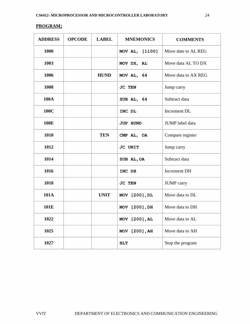
PROGRAM;
ADDRESS OPCODE LABEL MNEMONICS COMMENTS
1000 MOV AL, [1100] Move date to AL REG
1003 MOV DX, AL Move data AL TO DX
1006 HUND MOV AL, 64 Move data to AX REG
1008 JC TEN Jump carry
100A SUB AL, 64 Subtract data
100C INC DL Increment DL
100E JUP HUND JUMP label data
1010 TEN CMP AL, OA Compare register
1012 JC UNIT Jump carry
1014 SUB AL,OA Subtract data
1016 INC DH Increment DH
1018 JC TEN JUMP carry
101A UNIT MOV [200],DL Move data to DL
101E MOV [200],DH Move data to DH
1022 MOV [200],AL Move data to AL
1025 MOV [200],AH Move data to AH
1027 HLT Stop the program
CS6412- MICROPROCESSOR AND MICROCONTROLLER LABORATORY 25
VVIT DEPARTMENT OF ELECTRONICS AND COMMUNICATION ENGINEERING
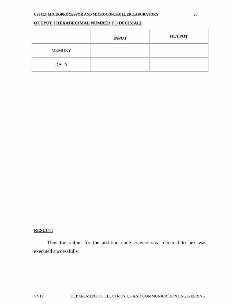
OUTPUT:[ HEXADECIMAL NUMBER TO DECIMAL]:
RESULT:
Thus the output for the addition code conversions –decimal to hex was
executed successfully.
INPUT OUTPUT
MEMORY
DATA
CS6412- MICROPROCESSOR AND MICROCONTROLLER LABORATORY 26
VVIT DEPARTMENT OF ELECTRONICS AND COMMUNICATION ENGINEERING
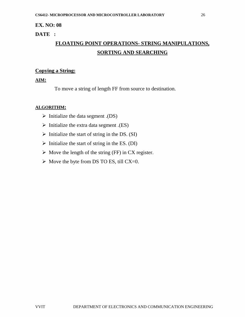
EX. NO: 08
DATE :
FLOATING POINT OPERATIONS- STRING MANIPULATIONS,
SORTING AND SEARCHING
Copying a String:
AIM:
To move a string of length FF from source to destination.
ALGORITHM:
Initialize the data segment .(DS)
Initialize the extra data segment .(ES)
Initialize the start of string in the DS. (SI)
Initialize the start of string in the ES. (DI)
Move the length of the string (FF) in CX register.
Move the byte from DS TO ES, till CX=0.

CS6412- MICROPROCESSOR AND MICROCONTROLLER LABORATORY 27
VVIT DEPARTMENT OF ELECTRONICS AND COMMUNICATION ENGINEERING
FLOECHART:
CS6412- MICROPROCESSOR AND MICROCONTROLLER LABORATORY 28
VVIT DEPARTMENT OF ELECTRONICS AND COMMUNICATION ENGINEERING
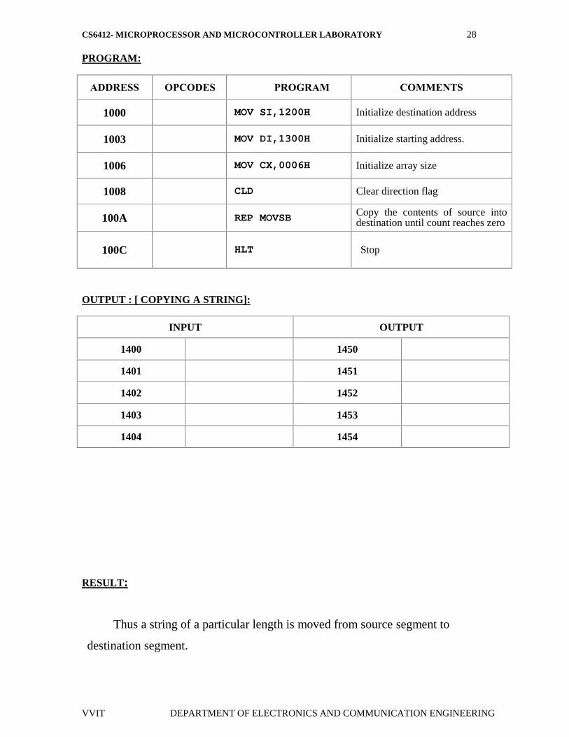
PROGRAM:
ADDRESS OPCODES PROGRAM COMMENTS
1000 MOV SI,1200H Initialize destination address
1003 MOV DI,1300H Initialize starting address.
1006 MOV CX,0006H Initialize array size
1008 CLD Clear direction flag
100A REP MOVSB Copy the contents of source intodestination until count reaches zero
100C HLT Stop
OUTPUT : [ COPYING A STRING]:
INPUT OUTPUT
1400 1450
1401 1451
1402 1452
1403 1453
1404 1454
RESULT:
Thus a string of a particular length is moved from source segment to
destination segment.
CS6412- MICROPROCESSOR AND MICROCONTROLLER LABORATORY 29
VVIT DEPARTMENT OF ELECTRONICS AND COMMUNICATION ENGINEERING
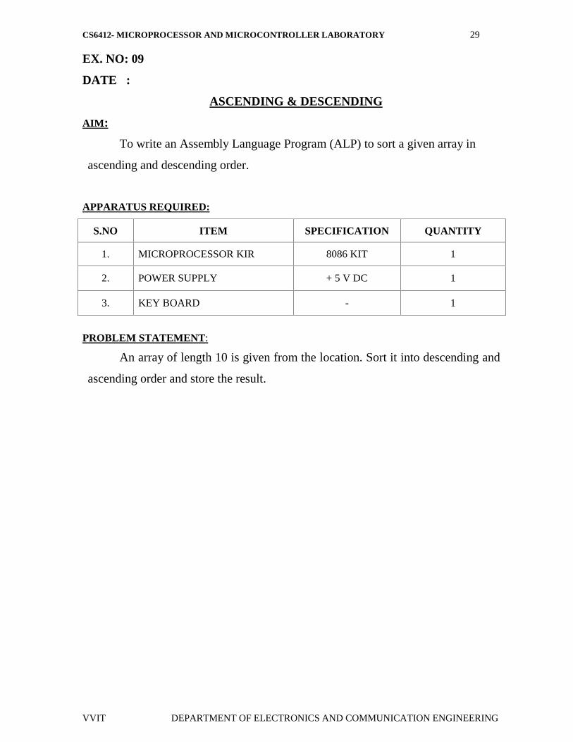
EX. NO: 09
DATE :
ASCENDING & DESCENDING
AIM:
To write an Assembly Language Program (ALP) to sort a given array in
ascending and descending order.
APPARATUS REQUIRED:
S.NO ITEM SPECIFICATION QUANTITY
1. MICROPROCESSOR KIR 8086 KIT 1
2. POWER SUPPLY + 5 V DC 1
3. KEY BOARD - 1
PROBLEM STATEMENT:
An array of length 10 is given from the location. Sort it into descending and
ascending order and store the result.

CS6412- MICROPROCESSOR AND MICROCONTROLLER LABORATORY 30
VVIT DEPARTMENT OF ELECTRONICS AND COMMUNICATION ENGINEERING
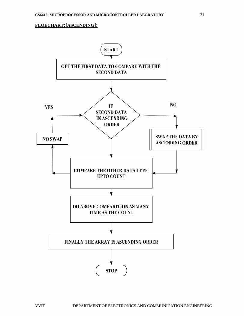
ALGORITHM:
Sorting in ascending order:
Load the array count in two registers C1 and C2.
Get the first two numbers.
Compare the numbers and exchange if necessary so that the two numbers are in
ascending order.
Decrement C2.
Get the third number from the array and repeat the process until C2 is 0.
Decrement C1 and repeat the process until C1 is 0.
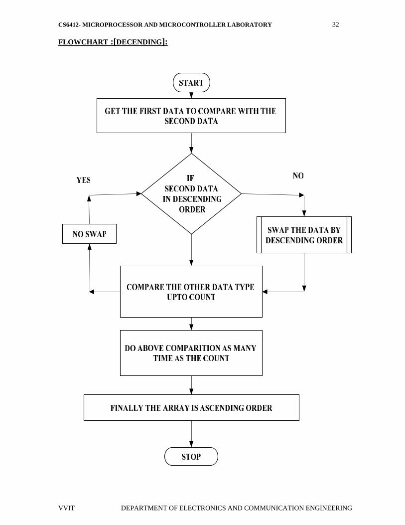
Sorting in descending order:
Load the array count in two registers C1 and C2.
Get the first two numbers.
Compare the numbers and exchange if necessary so that the two numbers are in
descending order.
Decrement C2.
Get the third number from the array and repeat the process until C2 is 0.
Decrement C1 and repeat the process until C1 is 0.
CS6412- MICROPROCESSOR AND MICROCONTROLLER LABORATORY 31
VVIT DEPARTMENT OF ELECTRONICS AND COMMUNICATION ENGINEERING
FLOECHART:[ASCENDING]:
CS6412- MICROPROCESSOR AND MICROCONTROLLER LABORATORY 32
VVIT DEPARTMENT OF ELECTRONICS AND COMMUNICATION ENGINEERING
FLOWCHART :[DECENDING]:
CS6412- MICROPROCESSOR AND MICROCONTROLLER LABORATORY 33
VVIT DEPARTMENT OF ELECTRONICS AND COMMUNICATION ENGINEERING
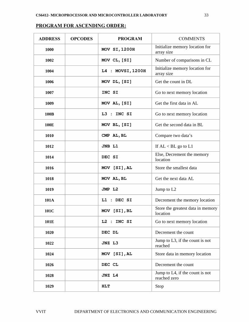
PROGRAM FOR ASCENDING ORDER:
ADDRESS OPCODES PROGRAM COMMENTS
1000 MOV SI,1200HInitialize memory location forarray size
1002 MOV CL,[SI] Number of comparisons in CL
1004 L4 : MOVSI,1200H Initialize memory location forarray size
1006 MOV DL,[SI] Get the count in DL
1007 INC SI Go to next memory location
1009 MOV AL,[SI] Get the first data in AL
100B L3 : INC SI Go to next memory location
100E MOV BL,[SI] Get the second data in BL
1010 CMP AL,BL Compare two data’s
1012 JNB L1 If AL < BL go to L1
1014 DEC SIElse, Decrement the memorylocation
1016 MOV [SI],AL Store the smallest data
1018 MOV AL,BL Get the next data AL
1019 JMP L2 Jump to L2
101A L1 : DEC SI Decrement the memory location
101C MOV [SI],BL Store the greatest data in memorylocation
101E L2 : INC SI Go to next memory location
1020 DEC DL Decrement the count
1022 JNZ L3Jump to L3, if the count is notreached
1024 MOV [SI],AL Store data in memory location
1026 DEC CL Decrement the count
1028 JNZ L4 Jump to L4, if the count is notreached zero
1029 HLT Stop
CS6412- MICROPROCESSOR AND MICROCONTROLLER LABORATORY 34
VVIT DEPARTMENT OF ELECTRONICS AND COMMUNICATION ENGINEERING
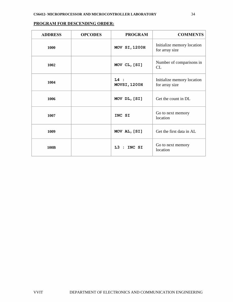
PROGRAM FOR DESCENDING ORDER:
ADDRESS OPCODES PROGRAM COMMENTS
1000 MOV SI,1200H Initialize memory locationfor array size
1002 MOV CL,[SI]Number of comparisons inCL
1004L4 :MOVSI,1200H
Initialize memory locationfor array size
1006 MOV DL,[SI] Get the count in DL
1007 INC SIGo to next memorylocation
1009 MOV AL,[SI] Get the first data in AL
100B L3 : INC SIGo to next memorylocation
CS6412- MICROPROCESSOR AND MICROCONTROLLER LABORATORY 35
VVIT DEPARTMENT OF ELECTRONICS AND COMMUNICATION ENGINEERING
OUTPUT FOR ASCENDING:
OUTPUT FOR DESCENDING ORDER:
RESULT:
Thus given array of numbers are sorted in ascending & descending order.
DATA
INPUT
OUTPUT
DATA
INPUT
OUTPUT
CS6412- MICROPROCESSOR AND MICROCONTROLLER LABORATORY 36
VVIT DEPARTMENT OF ELECTRONICS AND COMMUNICATION ENGINEERING
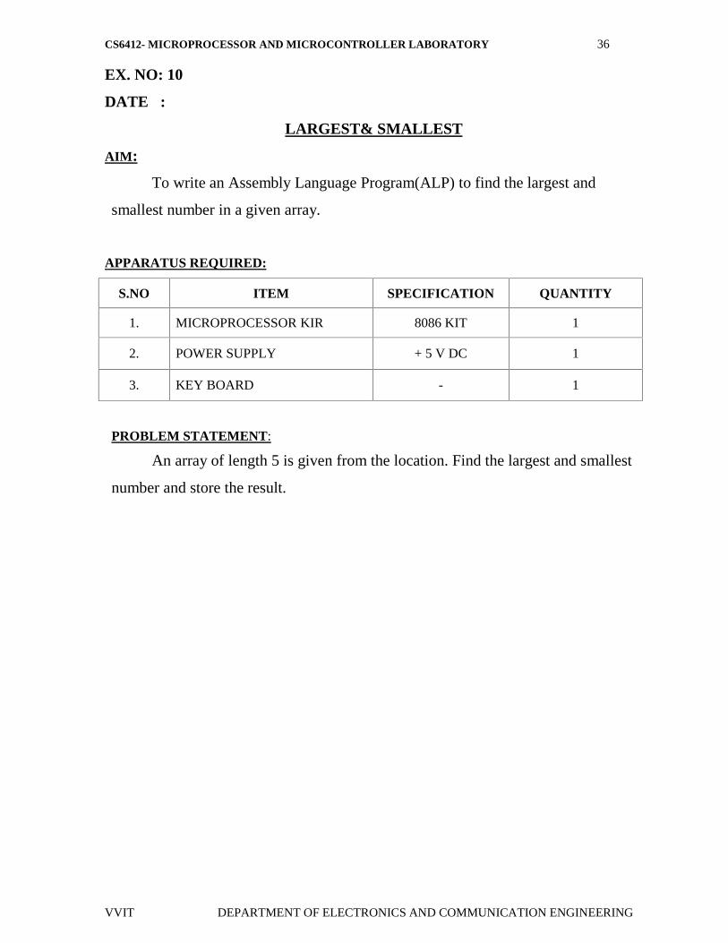
EX. NO: 10
DATE :
LARGEST& SMALLEST
AIM:
To write an Assembly Language Program(ALP) to find the largest and
smallest number in a given array.
APPARATUS REQUIRED:
S.NO ITEM SPECIFICATION QUANTITY
1. MICROPROCESSOR KIR 8086 KIT 1
2. POWER SUPPLY + 5 V DC 1
3. KEY BOARD - 1
PROBLEM STATEMENT:
An array of length 5 is given from the location. Find the largest and smallest
number and store the result.
CS6412- MICROPROCESSOR AND MICROCONTROLLER LABORATORY 37
VVIT DEPARTMENT OF ELECTRONICS AND COMMUNICATION ENGINEERING
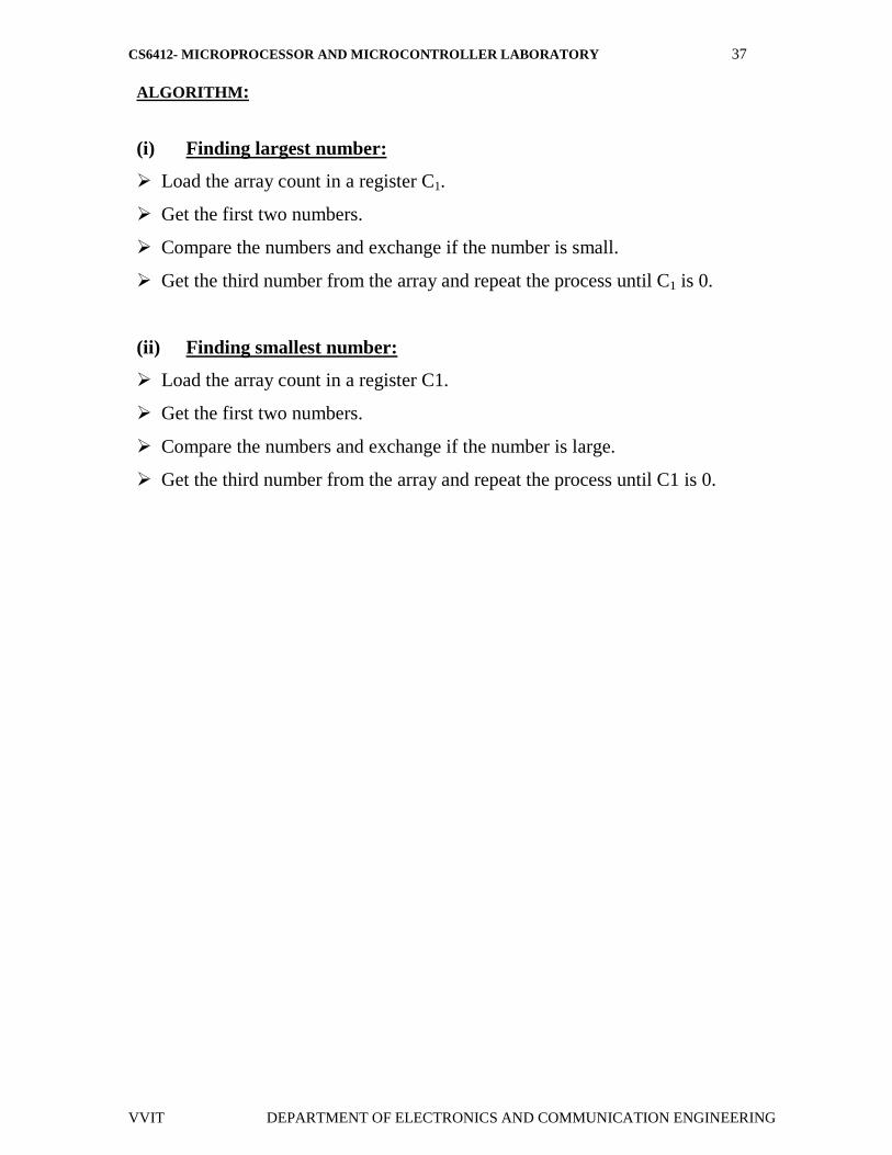
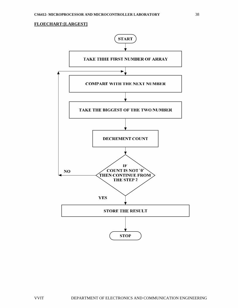
ALGORITHM:
(i) Finding largest number:
Load the array count in a register C1.
Get the first two numbers.
Compare the numbers and exchange if the number is small.
Get the third number from the array and repeat the process until C1 is 0.
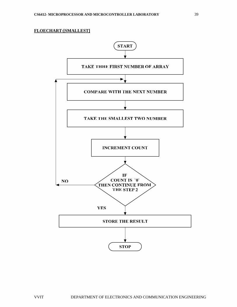
(ii) Finding smallest number:
Load the array count in a register C1.
Get the first two numbers.
Compare the numbers and exchange if the number is large.
Get the third number from the array and repeat the process until C1 is 0.
CS6412- MICROPROCESSOR AND MICROCONTROLLER LABORATORY 38
VVIT DEPARTMENT OF ELECTRONICS AND COMMUNICATION ENGINEERING
FLOECHART:[LARGEST]
CS6412- MICROPROCESSOR AND MICROCONTROLLER LABORATORY 39
VVIT DEPARTMENT OF ELECTRONICS AND COMMUNICATION ENGINEERING
FLOECHART:[SMALLEST]
CS6412- MICROPROCESSOR AND MICROCONTROLLER LABORATORY 40
VVIT DEPARTMENT OF ELECTRONICS AND COMMUNICATION ENGINEERING
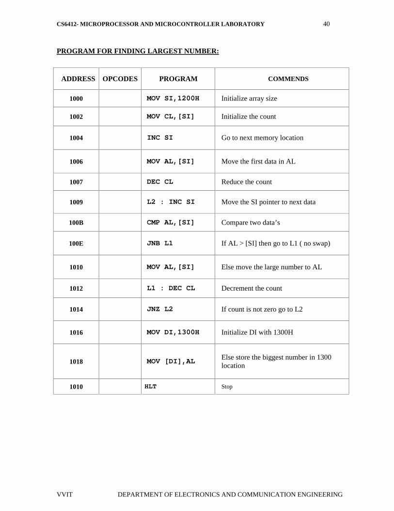
PROGRAM FOR FINDING LARGEST NUMBER:
ADDRESS OPCODES PROGRAM COMMENDS
1000 MOV SI,1200H Initialize array size
1002 MOV CL,[SI] Initialize the count
1004 INC SI Go to next memory location
1006 MOV AL,[SI] Move the first data in AL
1007 DEC CL Reduce the count
1009 L2 : INC SI Move the SI pointer to next data
100B CMP AL,[SI] Compare two data’s
100E JNB L1 If AL > [SI] then go to L1 ( no swap)
1010 MOV AL,[SI] Else move the large number to AL
1012 L1 : DEC CL Decrement the count
1014 JNZ L2 If count is not zero go to L2
1016 MOV DI,1300H Initialize DI with 1300H
1018 MOV [DI],AL Else store the biggest number in 1300location
1010 HLT Stop
CS6412- MICROPROCESSOR AND MICROCONTROLLER LABORATORY 41
VVIT DEPARTMENT OF ELECTRONICS AND COMMUNICATION ENGINEERING
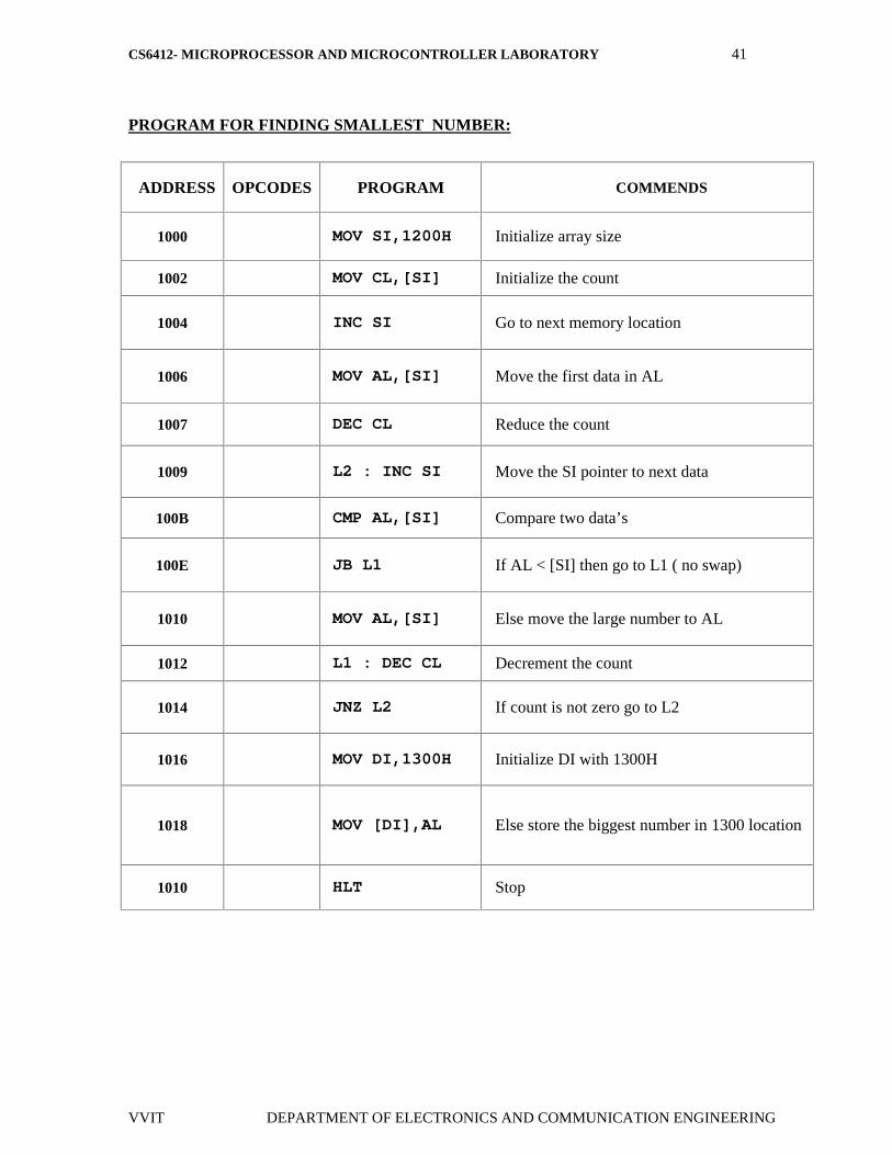
PROGRAM FOR FINDING SMALLEST NUMBER:
ADDRESS OPCODES PROGRAM COMMENDS
1000 MOV SI,1200H Initialize array size
1002 MOV CL,[SI] Initialize the count
1004 INC SI Go to next memory location
1006 MOV AL,[SI] Move the first data in AL
1007 DEC CL Reduce the count
1009 L2 : INC SI Move the SI pointer to next data
100B CMP AL,[SI] Compare two data’s
100E JB L1 If AL < [SI] then go to L1 ( no swap)
1010 MOV AL,[SI] Else move the large number to AL
1012 L1 : DEC CL Decrement the count
1014 JNZ L2 If count is not zero go to L2
1016 MOV DI,1300H Initialize DI with 1300H
1018 MOV [DI],AL Else store the biggest number in 1300 location
1010 HLT Stop
CS6412- MICROPROCESSOR AND MICROCONTROLLER LABORATORY 42
VVIT DEPARTMENT OF ELECTRONICS AND COMMUNICATION ENGINEERING
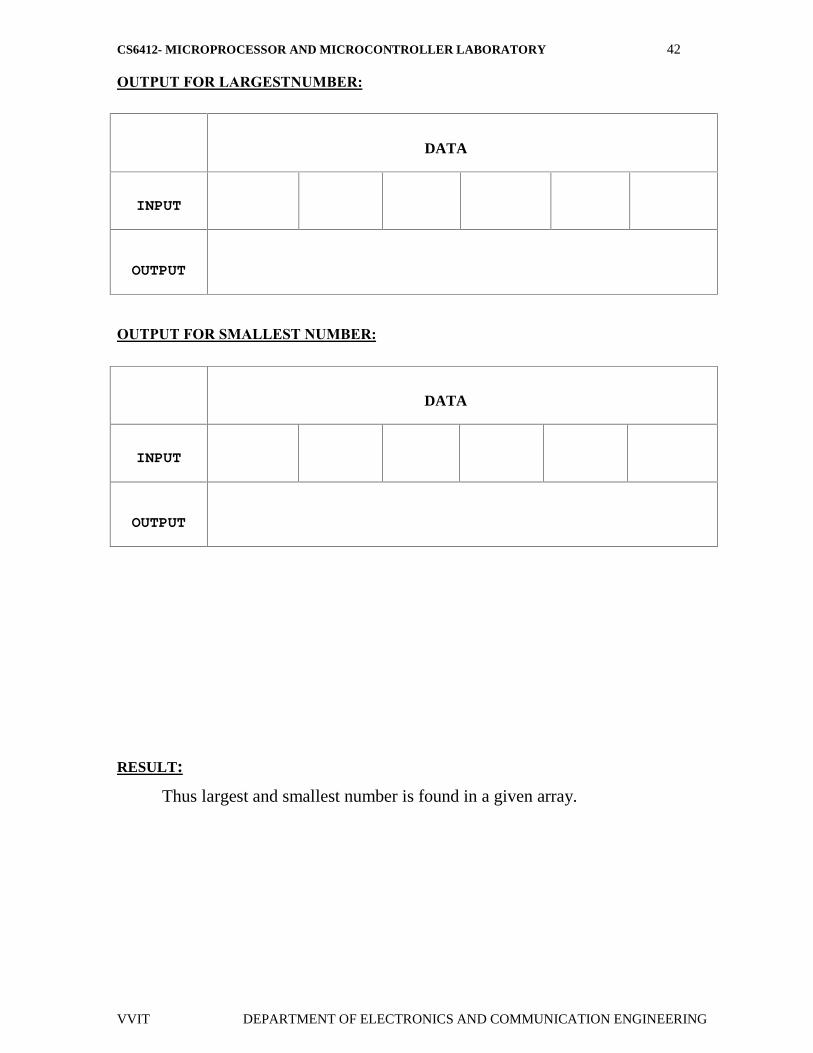
OUTPUT FOR LARGESTNUMBER:
OUTPUT FOR SMALLEST NUMBER:
RESULT:
Thus largest and smallest number is found in a given array.
DATA
INPUT
OUTPUT
DATA
INPUT
OUTPUT
CS6412- MICROPROCESSOR AND MICROCONTROLLER LABORATORY 43
VVIT DEPARTMENT OF ELECTRONICS AND COMMUNICATION ENGINEERING
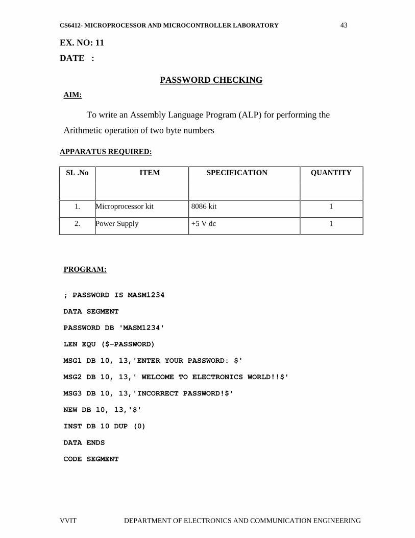
EX. NO: 11
DATE :
PASSWORD CHECKING
AIM:
To write an Assembly Language Program (ALP) for performing the
Arithmetic operation of two byte numbers
APPARATUS REQUIRED:
SL .No ITEM SPECIFICATION QUANTITY
1. Microprocessor kit 8086 kit 1
2. Power Supply +5 V dc 1
PROGRAM:
; PASSWORD IS MASM1234
DATA SEGMENT
PASSWORD DB 'MASM1234'
LEN EQU ($-PASSWORD)
MSG1 DB 10, 13,'ENTER YOUR PASSWORD: $'
MSG2 DB 10, 13,' WELCOME TO ELECTRONICS WORLD!!$'
MSG3 DB 10, 13,'INCORRECT PASSWORD!$'
NEW DB 10, 13,'$'
INST DB 10 DUP (0)
DATA ENDS
CODE SEGMENT
CS6412- MICROPROCESSOR AND MICROCONTROLLER LABORATORY 44
VVIT DEPARTMENT OF ELECTRONICS AND COMMUNICATION ENGINEERING
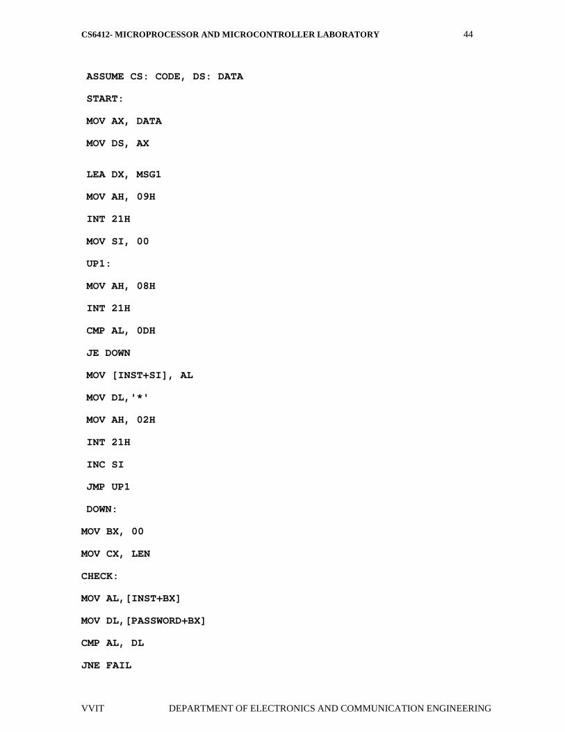
ASSUME CS: CODE, DS: DATA
START:
MOV AX, DATA
MOV DS, AX
LEA DX, MSG1
MOV AH, 09H
INT 21H
MOV SI, 00
UP1:
MOV AH, 08H
INT 21H
CMP AL, 0DH
JE DOWN
MOV [INST+SI], AL
MOV DL,'*'
MOV AH, 02H
INT 21H
INC SI
JMP UP1
DOWN:
MOV BX, 00
MOV CX, LEN
CHECK:
MOV AL,[INST+BX]
MOV DL,[PASSWORD+BX]
CMP AL, DL
JNE FAIL
CS6412- MICROPROCESSOR AND MICROCONTROLLER LABORATORY 45
VVIT DEPARTMENT OF ELECTRONICS AND COMMUNICATION ENGINEERING
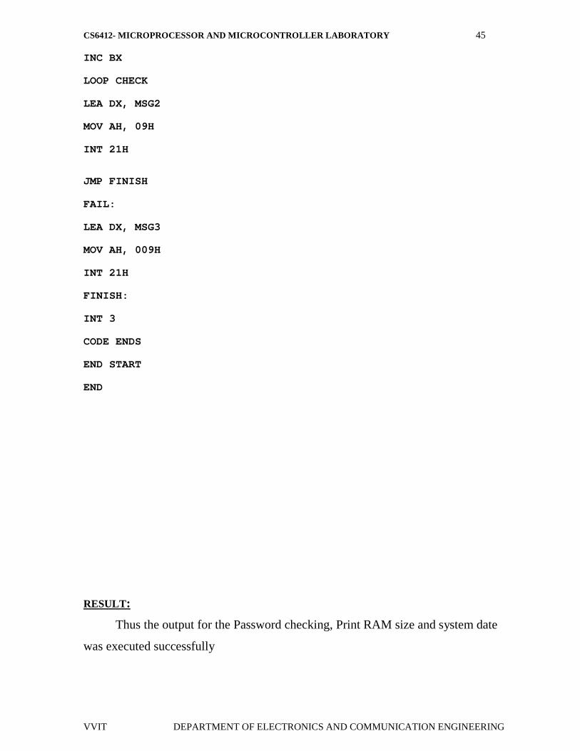
INC BX
LOOP CHECK
LEA DX, MSG2
MOV AH, 09H
INT 21H
JMP FINISH
FAIL:
LEA DX, MSG3
MOV AH, 009H
INT 21H
FINISH:
INT 3
CODE ENDS
END START
END
RESULT:
Thus the output for the Password checking, Print RAM size and system date
was executed successfully

CS6412- MICROPROCESSOR AND MICROCONTROLLER LABORATORY 46
VVIT DEPARTMENT OF ELECTRONICS AND COMMUNICATION ENGINEERING
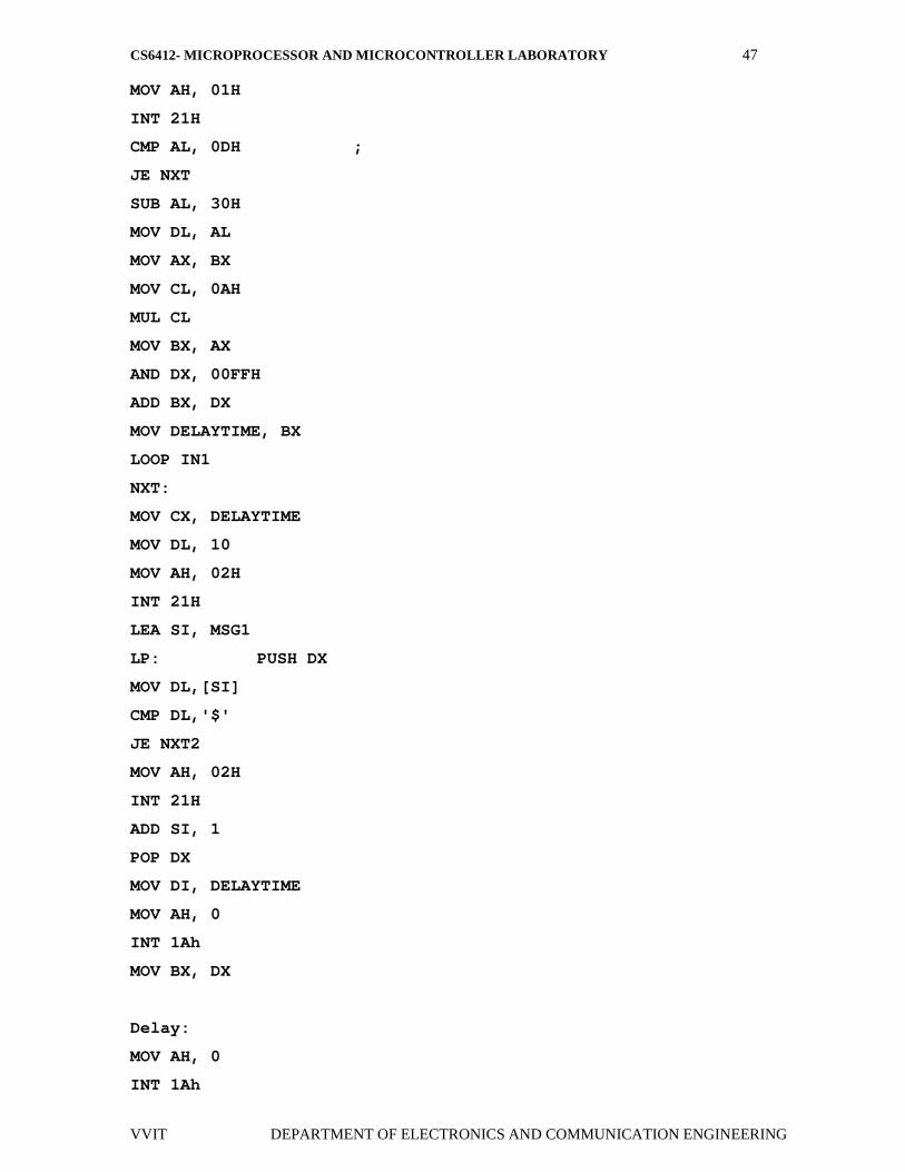
EX.NO: 12
DATE :
COUNTERS AND TIME DELAY
AIM:
To write an assembly language program in 8086 to Counters and Time Delay
APPARATUS REQUIRED:
SL .No ITEM SPECIFICATION QUANTITY
1. Microprocessor kit 8086 kit 1
2. Power Supply +5 V dc 1
PROGRAM:
.MODEL SMALL
.DATA
MSGIN DB 'Enter delay duration (0-50): $'
MSG1 DB 'This is Microprocessor! $'
DELAYTIME DW 0000H
.CODE
MOV DX,@DATA
MOV DS, DX
LEA DX, MSGIN
MOV AH, 09H
INT 21H
IN1:
CS6412- MICROPROCESSOR AND MICROCONTROLLER LABORATORY 47
VVIT DEPARTMENT OF ELECTRONICS AND COMMUNICATION ENGINEERING
MOV AH, 01H
INT 21H
CMP AL, 0DH ;
JE NXT
SUB AL, 30H
MOV DL, AL
MOV AX, BX
MOV CL, 0AH
MUL CL
MOV BX, AX
AND DX, 00FFH
ADD BX, DX
MOV DELAYTIME, BX
LOOP IN1
NXT:
MOV CX, DELAYTIME
MOV DL, 10
MOV AH, 02H
INT 21H
LEA SI, MSG1
LP: PUSH DX
MOV DL,[SI]
CMP DL,'$'
JE NXT2
MOV AH, 02H
INT 21H
ADD SI, 1
POP DX
MOV DI, DELAYTIME
MOV AH, 0
INT 1Ah
MOV BX, DX
Delay:
MOV AH, 0
INT 1Ah
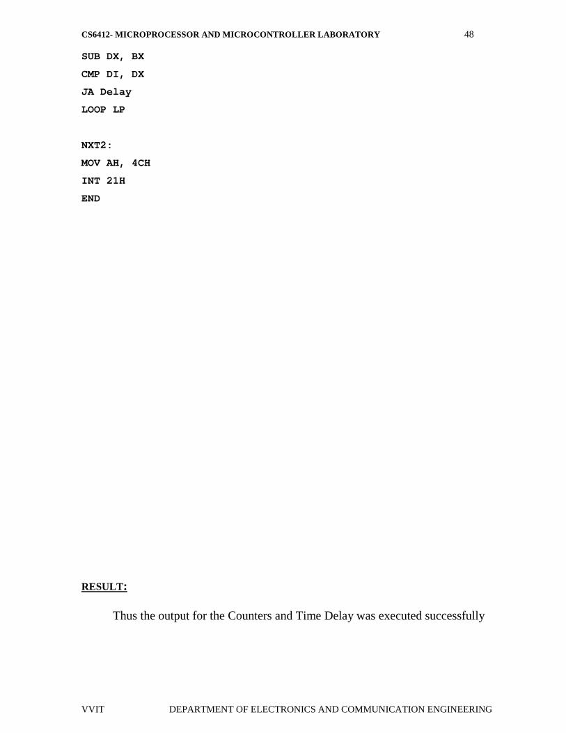
CS6412- MICROPROCESSOR AND MICROCONTROLLER LABORATORY 48
VVIT DEPARTMENT OF ELECTRONICS AND COMMUNICATION ENGINEERING
SUB DX, BX
CMP DI, DX
JA Delay
LOOP LP
NXT2:
MOV AH, 4CH
INT 21H
END
RESULT:
Thus the output for the Counters and Time Delay was executed successfully
CS6412- MICROPROCESSOR AND MICROCONTROLLER LABORATORY 49
VVIT DEPARTMENT OF ELECTRONICS AND COMMUNICATION ENGINEERING
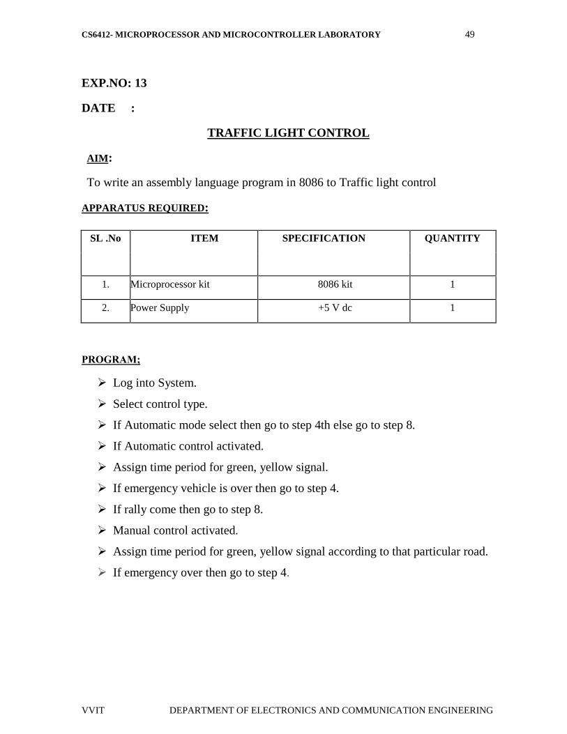
EXP.NO: 13
DATE :
TRAFFIC LIGHT CONTROL
AIM:
To write an assembly language program in 8086 to Traffic light control
APPARATUS REQUIRED:
SL .No ITEM SPECIFICATION QUANTITY
1. Microprocessor kit 8086 kit 1
2. Power Supply +5 V dc 1
PROGRAM;
Log into System.
Select control type.
If Automatic mode select then go to step 4th else go to step 8.
If Automatic control activated.
Assign time period for green, yellow signal.
If emergency vehicle is over then go to step 4.
If rally come then go to step 8.
Manual control activated.
Assign time period for green, yellow signal according to that particular road.
If emergency over then go to step 4.

CS6412- MICROPROCESSOR AND MICROCONTROLLER LABORATORY 50
VVIT DEPARTMENT OF ELECTRONICS AND COMMUNICATION ENGINEERING
MODEL GRAPH FOR TRAFFIC LIGHT CONTROL:
CS6412- MICROPROCESSOR AND MICROCONTROLLER LABORATORY 51
VVIT DEPARTMENT OF ELECTRONICS AND COMMUNICATION ENGINEERING
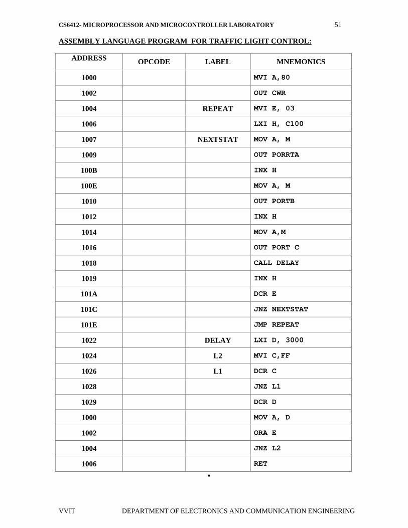
ASSEMBLY LANGUAGE PROGRAM FOR TRAFFIC LIGHT CONTROL:
ADDRESS OPCODE LABEL MNEMONICS
1000 MVI A,80
1002 OUT CWR
1004 REPEAT MVI E, 03
1006 LXI H, C100
1007 NEXTSTAT MOV A, M
1009 OUT PORRTA
100B INX H
100E MOV A, M
1010 OUT PORTB
1012 INX H
1014 MOV A,M
1016 OUT PORT C
1018 CALL DELAY
1019 INX H
101A DCR E
101C JNZ NEXTSTAT
101E JMP REPEAT
1022 DELAY LXI D, 3000
1024 L2 MVI C,FF
1026 L1 DCR C
1028 JNZ L1
1029 DCR D
1000 MOV A, D
1002 ORA E
1004 JNZ L2
1006 RET
CS6412- MICROPROCESSOR AND MICROCONTROLLER LABORATORY 52
VVIT DEPARTMENT OF ELECTRONICS AND COMMUNICATION ENGINEERING
RESULT:
Thus the assembly language program for traffic light control is verified
CS6412- MICROPROCESSOR AND MICROCONTROLLER LABORATORY 53
VVIT DEPARTMENT OF ELECTRONICS AND COMMUNICATION ENGINEERING
EX. NO: 14
DATE :
STEPPER MOTOR INTERFACING
AIM:
To write an assembly language program in 8086 to rotate the motor atdifferent speeds.
APPARATUS REQUIRED:
SL.NO ITEM SPECIFICATION QUANTITY
1. Microprocessor kit 8086 1
2. Power Supply +5 V, dc,+12 V dc 1
3. Stepper Motor Interface board - 1
4. Stepper Motor - 1
PROBLEM STATEMENT:
Write a code for achieving a specific angle of rotation in a given time and
particular number of rotations in a specific time.
THEORY:
A motor in which the rotor is able to assume only discrete stationary
angular position is a stepper motor. The rotary motion occurs in a stepwise manner
from one equilibrium position to the next. Two-phase scheme: Any two adjacent
stator windings are energized. There are two magnetic fields active in quadrature
and none of the rotor pole faces can be in direct alignment with the stator poles. A
partial but symmetric alignment of the rotor poles is of course possible.
CS6412- MICROPROCESSOR AND MICROCONTROLLER LABORATORY 54
VVIT DEPARTMENT OF ELECTRONICS AND COMMUNICATION ENGINEERING
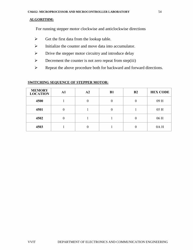
ALGORITHM:
For running stepper motor clockwise and anticlockwise directions
Get the first data from the lookup table.
Initialize the counter and move data into accumulator.
Drive the stepper motor circuitry and introduce delay
Decrement the counter is not zero repeat from step(iii)
Repeat the above procedure both for backward and forward directions.
SWITCHING SEQUENCE OF STEPPER MOTOR:
MEMORYLOCATION A1 A2 B1 B2 HEX CODE
4500 1 0 0 0 09 H
4501 0 1 0 1 05 H
4502 0 1 1 0 06 H
4503 1 0 1 0 0A H
CS6412- MICROPROCESSOR AND MICROCONTROLLER LABORATORY 55
VVIT DEPARTMENT OF ELECTRONICS AND COMMUNICATION ENGINEERING
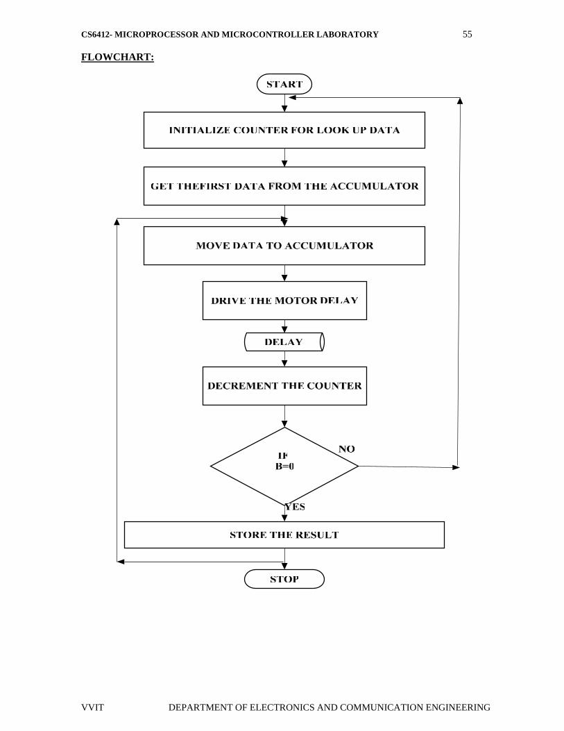
FLOWCHART:

CS6412- MICROPROCESSOR AND MICROCONTROLLER LABORATORY 56
VVIT DEPARTMENT OF ELECTRONICS AND COMMUNICATION ENGINEERING
PROGRAM FOR STEPPER MOTOR CONTOL;
ADDRESS OPCODE PROGRAM COMMENTS
1000START : MOVDI, 1200H
Initialize memory location to store the arrayof number
1002 MOV CX, 0004H Initialize array size
1004LOOP 1 : MOVAL,[DI] Copy the first data in AL
1006 OUT 0C0,AL Send it through port address
1007 MOV DX, 1010H Introduce delay
1009 L1 : DEC DX Declare DX
100B JNZ L1 JUNP no zero
100E INC DI Increment DI
1010 LOOP LOOP1 Go to next memory location
1012 JMP START Loop until all the data’s have been sent Go tostart location for continuous rotation
10141200 :09,05,06,0A Array of data’s
RESULT:
Thus the assembly language program for rotating stepper motor in both
clockwise and anticlockwise directions is written and verified.
CS6412- MICROPROCESSOR AND MICROCONTROLLER LABORATORY 57
VVIT DEPARTMENT OF ELECTRONICS AND COMMUNICATION ENGINEERING
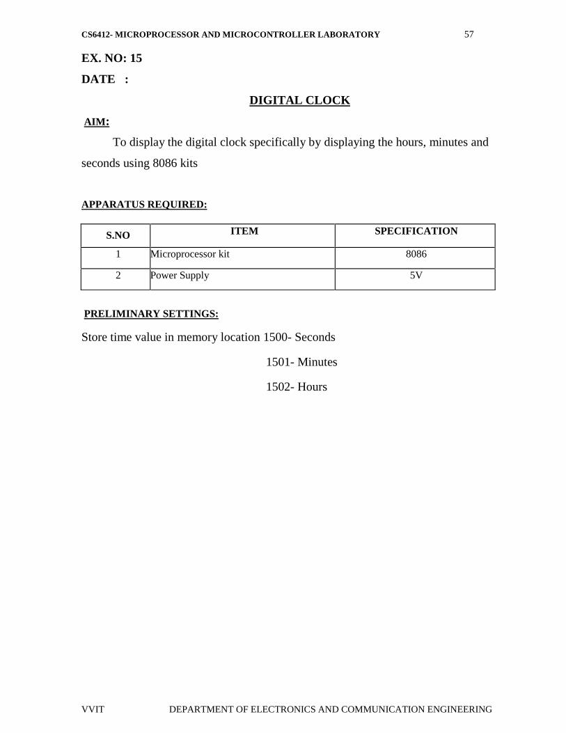
EX. NO: 15
DATE :
DIGITAL CLOCK
AIM:
To display the digital clock specifically by displaying the hours, minutes and
seconds using 8086 kits
APPARATUS REQUIRED:
PRELIMINARY SETTINGS:
Store time value in memory location 1500- Seconds
1501- Minutes
1502- Hours
S.NO ITEM SPECIFICATION
1 Microprocessor kit 8086
2 Power Supply 5V

CS6412- MICROPROCESSOR AND MICROCONTROLLER LABORATORY 58
VVIT DEPARTMENT OF ELECTRONICS AND COMMUNICATION ENGINEERING
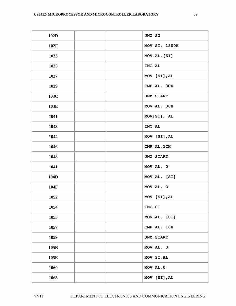
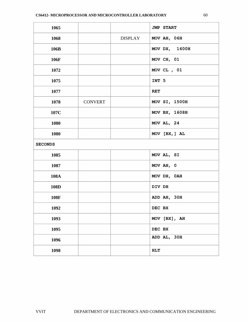
DIGITAL CLOCK PROGRAM:
MEMORY OPCODE LABEL MNEMONICS
1000 START
1000 CALL CONVERT
1003 CALL DISPLAY
1006 DELAY MOV AL, 0B0H
1009 OUT 16H, AL
100B MOV CL, 07H
100E S2 MOV AL, 88H
1011 OUT 14H, AL
1013 MOV AL, 80H
1016 OUT 14H, AL
1018 S1 MOV AL, 80H
101BOUT 16H, AL
101D NOP
101E NOP
101F NOP
1020 NOP
1021 IN AL, 14H
1023 MOV DL, AL
1025 IN AL, 14H
1027 OR AL,DL
1029 JNZ S1
102B DEC CL
CS6412- MICROPROCESSOR AND MICROCONTROLLER LABORATORY 59
VVIT DEPARTMENT OF ELECTRONICS AND COMMUNICATION ENGINEERING
102D JNZ S2
102F MOV SI, 1500H
1033 MOV AL.[SI]
1035 INC AL
1037 MOV [SI],AL
1039 CMP AL, 3CH
103C JNZ START
103E MOV AL, 00H
1041 MOV[SI], AL
1043 INC AL
1044 MOV [SI],AL
1046 CMP AL,3CH
1048 JNZ START
1041 MOV AL, 0
104D MOV AL, [SI]
104F MOV AL, O
1052 MOV [SI],AL
1054 INC SI
1055 MOV AL, [SI]
1057 CMP AL, 18H
1059 JNZ START
105B MOV AL, 0
105E MOV SI,AL
1060 MOV AL,0
1063 MOV [SI],AL
CS6412- MICROPROCESSOR AND MICROCONTROLLER LABORATORY 60
VVIT DEPARTMENT OF ELECTRONICS AND COMMUNICATION ENGINEERING
1065 JMP START
1068 DISPLAY MOV AH, 06H
106B MOV DX, 1600H
106F MOV CH, 01
1072 MOV CL , 01
1075 INT 5
1077 RET
1078 CONVERT MOV SI, 1500H
107C MOV BX, 1608H
1080 MOV AL, 24
1080 MOV [BX,] AL
SECONDS
1085 MOV AL, SI
1087 MOV AH, 0
108A MOV DH, 0AH
108D DIV DH
108F ADD AH, 30H
1092 DEC BX
1093 MOV [BX], AH
1095 DEC BX
1096ADD AL, 30H
1098 HLT

CS6412- MICROPROCESSOR AND MICROCONTROLLER LABORATORY 61
VVIT DEPARTMENT OF ELECTRONICS AND COMMUNICATION ENGINEERING
RESULT;
Thus the digital clock program has been written and executed using 8086
microprocessor kit and the output of digital clock was displayed as [hours: minutes:
seconds] successfully.
CS6412- MICROPROCESSOR AND MICROCONTROLLER LABORATORY 62
VVIT DEPARTMENT OF ELECTRONICS AND COMMUNICATION ENGINEERING
EX. NO: 16
DATE :
INTERFACING PRGRAMMABLE KEYBOARD AND
DISPLAY CONTROLLER- 8279
AIM :To display the rolling message “HELP US “ in the display.
APPARATUS REQUIRED:
8086 Microprocessor kit, Power supply, interfacing board.
ALGORITHM :
Display of rolling message “HELP US “
Initialize the counter
Set 8279 for 8 digit character display, right entry
Set 8279 for clearing the display
Write the command to display
Load the character into accumulator and display it
Introduce the delay
Repeat from step 1.
CS6412- MICROPROCESSOR AND MICROCONTROLLER LABORATORY 63
VVIT DEPARTMENT OF ELECTRONICS AND COMMUNICATION ENGINEERING
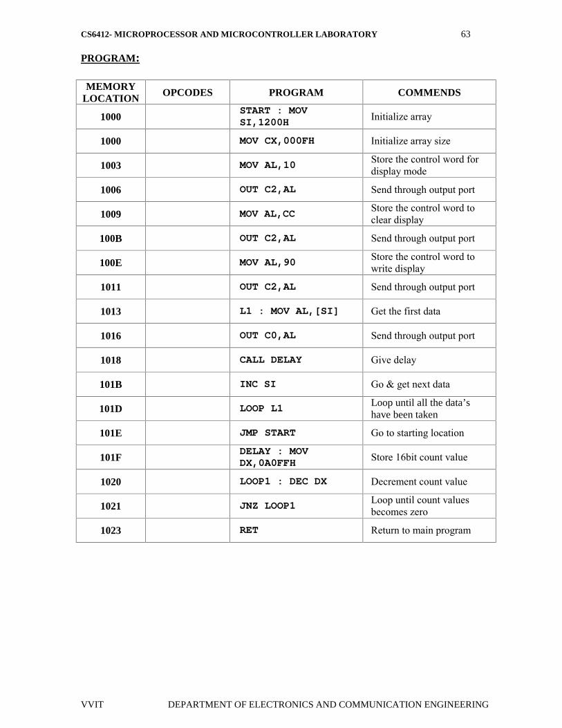
PROGRAM:
MEMORYLOCATION OPCODES PROGRAM COMMENDS
1000START : MOVSI,1200H Initialize array
1000 MOV CX,000FH Initialize array size
1003 MOV AL,10 Store the control word fordisplay mode
1006 OUT C2,AL Send through output port
1009 MOV AL,CCStore the control word toclear display
100B OUT C2,AL Send through output port
100E MOV AL,90 Store the control word towrite display
1011 OUT C2,AL Send through output port
1013 L1 : MOV AL,[SI] Get the first data
1016 OUT C0,AL Send through output port
1018 CALL DELAY Give delay
101B INC SI Go & get next data
101D LOOP L1 Loop until all the data’shave been taken
101E JMP START Go to starting location
101FDELAY : MOVDX,0A0FFH Store 16bit count value
1020 LOOP1 : DEC DX Decrement count value
1021 JNZ LOOP1Loop until count valuesbecomes zero
1023 RET Return to main program
CS6412- MICROPROCESSOR AND MICROCONTROLLER LABORATORY 64
VVIT DEPARTMENT OF ELECTRONICS AND COMMUNICATION ENGINEERING
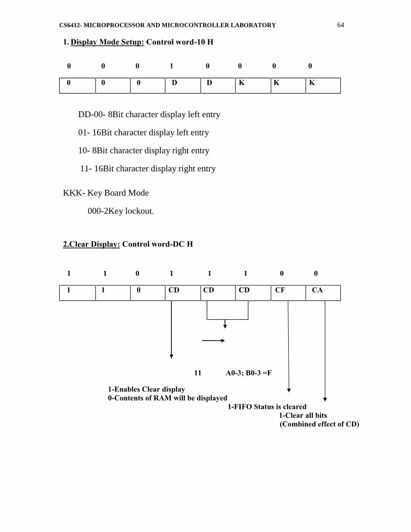
1. Display Mode Setup: Control word-10 H
0 0 0 1 0 0 0 0
0 0 0 D D K K K
DD-00- 8Bit character display left entry
01- 16Bit character display left entry
10- 8Bit character display right entry
11- 16Bit character display right entry
KKK- Key Board Mode
000-2Key lockout.
2.Clear Display: Control word-DC H
1 1 0 1 1 1 0 0
1 1 0 CD CD CD CF CA
11 A0-3; B0-3 =F
1-Enables Clear display0-Contents of RAM will be displayed
1-FIFO Status is cleared1-Clear all bits(Combined effect of CD)
CS6412- MICROPROCESSOR AND MICROCONTROLLER LABORATORY 65
VVIT DEPARTMENT OF ELECTRONICS AND COMMUNICATION ENGINEERING
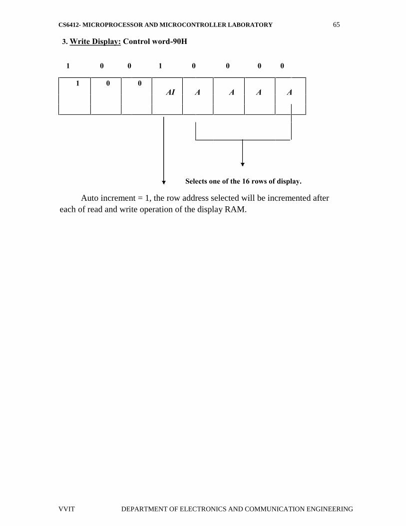
3. Write Display: Control word-90H
1 0 0 1 0 0 0 0
1 0 0AI A A A A
Selects one of the 16 rows of display.
Auto increment = 1, the row address selected will be incremented aftereach of read and write operation of the display RAM.

CS6412- MICROPROCESSOR AND MICROCONTROLLER LABORATORY 66
VVIT DEPARTMENT OF ELECTRONICS AND COMMUNICATION ENGINEERING
FLOWCHART:
CS6412- MICROPROCESSOR AND MICROCONTROLLER LABORATORY 67
VVIT DEPARTMENT OF ELECTRONICS AND COMMUNICATION ENGINEERING
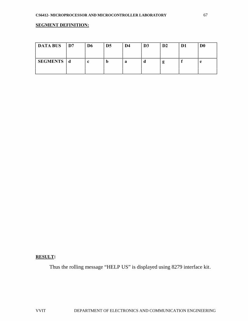
SEGMENT DEFINITION:
DATA BUS D7 D6 D5 D4 D3 D2 D1 D0
SEGMENTS d c b a d g f e
RESULT:
Thus the rolling message “HELP US” is displayed using 8279 interface kit.
CS6412- MICROPROCESSOR AND MICROCONTROLLER LABORATORY 68
VVIT DEPARTMENT OF ELECTRONICS AND COMMUNICATION ENGINEERING
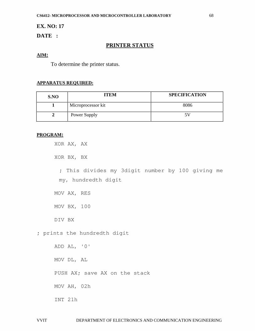
EX. NO: 17
DATE :
PRINTER STATUS
AIM:
To determine the printer status.
APPARATUS REQUIRED:
PROGRAM:
XOR AX, AX
XOR BX, BX
; This divides my 3digit number by 100 giving me
my, hundredth digit
MOV AX, RES
MOV BX, 100
DIV BX
; prints the hundredth digit
ADD AL, '0'
MOV DL, AL
PUSH AX; save AX on the stack
MOV AH, 02h
INT 21h
S.NO ITEM SPECIFICATION
1 Microprocessor kit 8086
2 Power Supply 5V
CS6412- MICROPROCESSOR AND MICROCONTROLLER LABORATORY 69
VVIT DEPARTMENT OF ELECTRONICS AND COMMUNICATION ENGINEERING
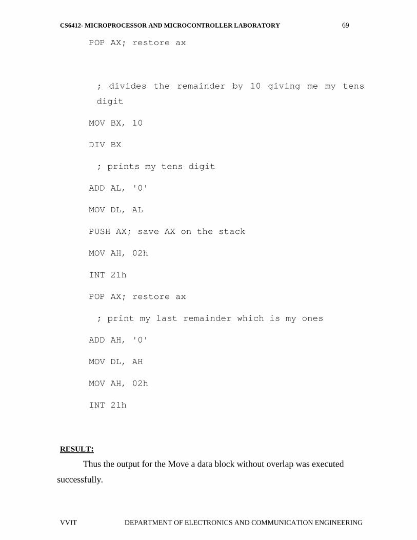
POP AX; restore ax
; divides the remainder by 10 giving me my tens
digit
MOV BX, 10
DIV BX
; prints my tens digit
ADD AL, '0'
MOV DL, AL
PUSH AX; save AX on the stack
MOV AH, 02h
INT 21h
POP AX; restore ax
; print my last remainder which is my ones
ADD AH, '0'
MOV DL, AH
MOV AH, 02h
INT 21h
RESULT:
Thus the output for the Move a data block without overlap was executed
successfully.
CS6412- MICROPROCESSOR AND MICROCONTROLLER LABORATORY 70
VVIT DEPARTMENT OF ELECTRONICS AND COMMUNICATION ENGINEERING
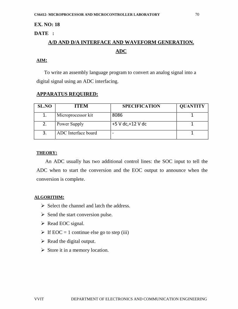
EX. NO: 18
DATE :
A/D AND D/A INTERFACE AND WAVEFORM GENERATION.
ADC
AIM:
To write an assembly language program to convert an analog signal into a
digital signal using an ADC interfacing.
APPARATUS REQUIRED:
SL.NO ITEM SPECIFICATION QUANTITY
1. Microprocessor kit 8086 1
2. Power Supply +5 V dc,+12 V dc 1
3. ADC Interface board - 1
THEORY:
An ADC usually has two additional control lines: the SOC input to tell the
ADC when to start the conversion and the EOC output to announce when the
conversion is complete.
ALGORITHM:
Select the channel and latch the address.
Send the start conversion pulse.
Read EOC signal.
If EOC = 1 continue else go to step (iii)
Read the digital output.
Store it in a memory location.

CS6412- MICROPROCESSOR AND MICROCONTROLLER LABORATORY 71
VVIT DEPARTMENT OF ELECTRONICS AND COMMUNICATION ENGINEERING
PROGRAM:
MEMORYLOCATION
OPCODES PROGRAM COMMENTS
1000 MOV AL,00Load accumulatorwith value for ALEhigh
1000 OUT 0C8H,ALSend through outputport
1003 MOV AL,08Load accumulatorwith value for ALElow
1006 OUT 0C8H,AL Send through outputport
1009 MOV AL,01Store the value tomake SOC high inthe accumulator
100B OUT 0D0H,AL Send through outputport
100E MOV AL,00
Introduce delay
1011 MOV AL,00
1013 MOV AL,00
1016 MOV AL,00
1018 OUT 0D0H,ALStore the value tomake SOC low theaccumulator
101B L1 : IN AL, 0D8H Send through outputport
101D AND AL,01
Read the EOC signalfrom port & checkfor end of conversion
101E CMP AL,01
101F JNZ L1
CS6412- MICROPROCESSOR AND MICROCONTROLLER LABORATORY 72
VVIT DEPARTMENT OF ELECTRONICS AND COMMUNICATION ENGINEERING
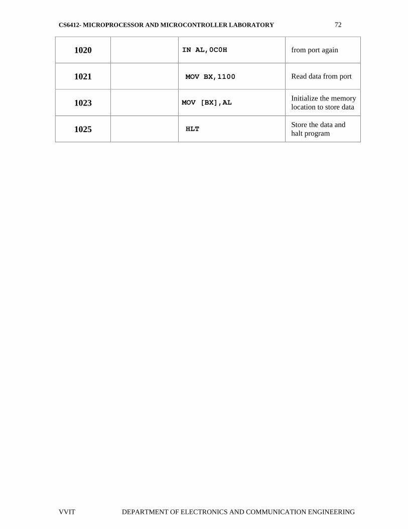
1020 IN AL,0C0H from port again
1021 MOV BX,1100 Read data from port
1023 MOV [BX],AL Initialize the memorylocation to store data
1025 HLT Store the data andhalt program

CS6412- MICROPROCESSOR AND MICROCONTROLLER LABORATORY 73
VVIT DEPARTMENT OF ELECTRONICS AND COMMUNICATION ENGINEERING
FLOWCHART:
CS6412- MICROPROCESSOR AND MICROCONTROLLER LABORATORY 74
VVIT DEPARTMENT OF ELECTRONICS AND COMMUNICATION ENGINEERING
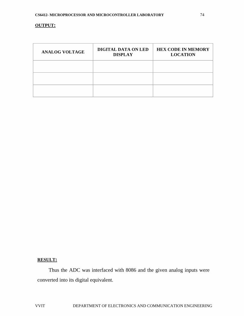
OUTPUT:
ANALOG VOLTAGE DIGITAL DATA ON LEDDISPLAY
HEX CODE IN MEMORYLOCATION
RESULT:
Thus the ADC was interfaced with 8086 and the given analog inputs were
converted into its digital equivalent.

CS6412- MICROPROCESSOR AND MICROCONTROLLER LABORATORY 75
VVIT DEPARTMENT OF ELECTRONICS AND COMMUNICATION ENGINEERING
EX. NO: 19DATE :
INTERFACING DIGITAL – TO – ANALOG CONVERTER
AIM:
1. To write an assembly language program for digital to analog conversion2. To convert digital inputs into analog outputs & To generate different
waveforms
APPARATUS REQUIRED:
SL.NO ITEM SPECIFICATION QUANTITY
1. Microprocessor kit 8086 Vi Microsystems 1
2. Power Supply +5 V, dc,+12 V dc 1
3. DAC Interface board - 1
PROBLEM STATEMENT:
The program is executed for various digital values and equivalent analogvoltages are measured and also the waveforms are measured at the output portsusing CRO.
THEORY:
Since DAC 0800 is an 8 bit DAC and the output voltage variation isbetween –5v and +5v. The output voltage varies in steps of 10/256 = 0.04(approximately). The digital data input and the corresponding output voltages arepresented in the table. The basic idea behind the generation of waveforms is thecontinuous generation of analog output of DAC. With 00 (Hex) as input to DAC2the analog output is –5v. Similarly with FF H as input, the output is +5v.Outputting digital data 00 and FF at regular intervals, to DAC2, results in a squarewave of amplitude 5v.Output digital data from 00 to FF in constant steps of 01 toDAC2. Repeat this sequence again and again. As a result a saw-tooth wave will begenerated at DAC2 output. Output digital data from 00 to FF in constant steps of01 to DAC2. Output digital data from FF to 00 in constant steps of 01 to DAC2.
CS6412- MICROPROCESSOR AND MICROCONTROLLER LABORATORY 76
VVIT DEPARTMENT OF ELECTRONICS AND COMMUNICATION ENGINEERING
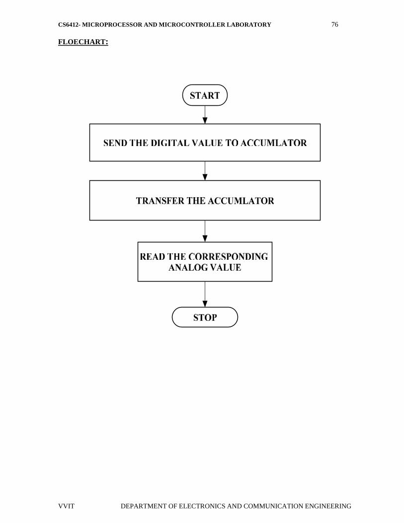
FLOECHART:
CS6412- MICROPROCESSOR AND MICROCONTROLLER LABORATORY 77
VVIT DEPARTMENT OF ELECTRONICS AND COMMUNICATION ENGINEERING
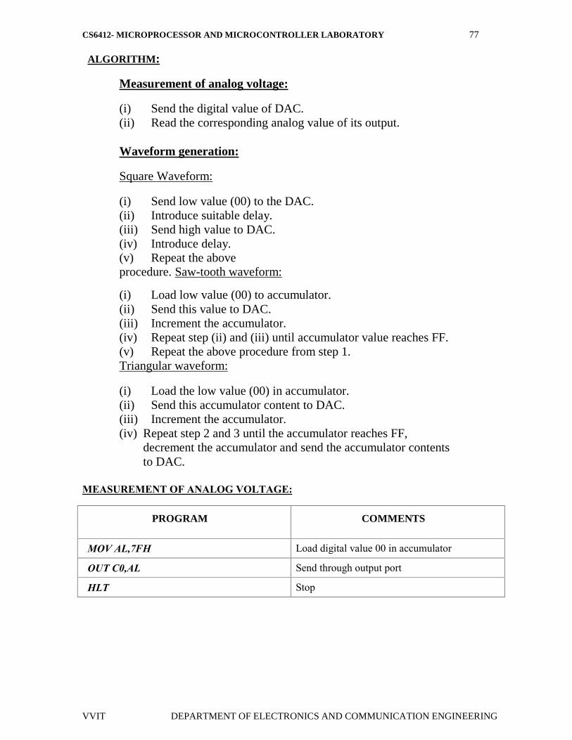
ALGORITHM:
Measurement of analog voltage:
(i) Send the digital value of DAC.(ii) Read the corresponding analog value of its output.
Waveform generation:
Square Waveform:
(i) Send low value (00) to the DAC.(ii) Introduce suitable delay.(iii) Send high value to DAC.(iv) Introduce delay.(v) Repeat the aboveprocedure. Saw-tooth waveform:
(i) Load low value (00) to accumulator.(ii) Send this value to DAC.(iii) Increment the accumulator.(iv) Repeat step (ii) and (iii) until accumulator value reaches FF.(v) Repeat the above procedure from step 1.Triangular waveform:
(i) Load the low value (00) in accumulator.(ii) Send this accumulator content to DAC.(iii) Increment the accumulator.(iv) Repeat step 2 and 3 until the accumulator reaches FF,
decrement the accumulator and send the accumulator contentsto DAC.
MEASUREMENT OF ANALOG VOLTAGE:
PROGRAM COMMENTS
MOV AL,7FH Load digital value 00 in accumulator
OUT C0,AL Send through output port
HLT Stop
CS6412- MICROPROCESSOR AND MICROCONTROLLER LABORATORY 78
VVIT DEPARTMENT OF ELECTRONICS AND COMMUNICATION ENGINEERING
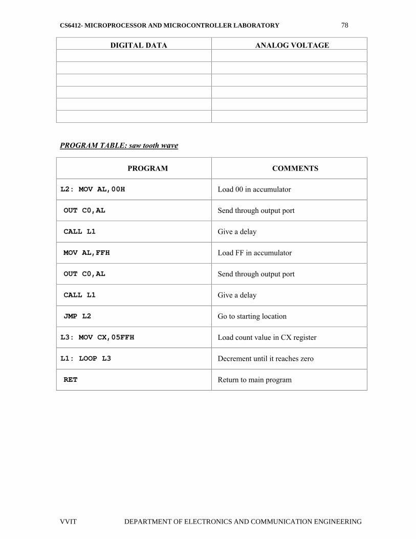
DIGITAL DATA ANALOG VOLTAGE
PROGRAM TABLE: saw tooth wave
PROGRAM COMMENTS
L2: MOV AL,00H Load 00 in accumulator
OUT C0,AL Send through output port
CALL L1 Give a delay
MOV AL,FFH Load FF in accumulator
OUT C0,AL Send through output port
CALL L1 Give a delay
JMP L2 Go to starting location
L3: MOV CX,05FFH Load count value in CX register
L1: LOOP L3 Decrement until it reaches zero
RET Return to main program
CS6412- MICROPROCESSOR AND MICROCONTROLLER LABORATORY 79
VVIT DEPARTMENT OF ELECTRONICS AND COMMUNICATION ENGINEERING
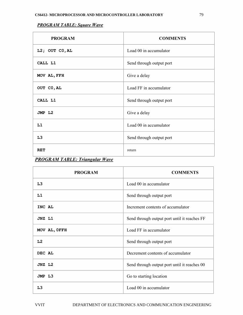
PROGRAM TABLE: Square Wave
PROGRAM COMMENTS
L2; OUT C0,AL Load 00 in accumulator
CALL L1 Send through output port
MOV AL,FFH Give a delay
OUT C0,AL Load FF in accumulator
CALL L1 Send through output port
JMP L2 Give a delay
L1 Load 00 in accumulator
L3 Send through output port
RET return
PROGRAM TABLE: Triangular Wave
PROGRAM COMMENTS
L3 Load 00 in accumulator
L1 Send through output port
INC AL Increment contents of accumulator
JNZ L1 Send through output port until it reaches FF
MOV AL,0FFH Load FF in accumulator
L2 Send through output port
DEC AL Decrement contents of accumulator
JNZ L2 Send through output port until it reaches 00
JMP L3 Go to starting location
L3 Load 00 in accumulator

CS6412- MICROPROCESSOR AND MICROCONTROLLER LABORATORY 80
VVIT DEPARTMENT OF ELECTRONICS AND COMMUNICATION ENGINEERING
WAVEFORM GENERATION:
WAVEFORMS AMPLITUDE TIMEPERIOD
Square Waveform
Saw-tooth waveform
Triangular waveform
RESULT
Thus the DAC was interfaced with 8085 and different waveforms have been
generated.
CS6412- MICROPROCESSOR AND MICROCONTROLLER LABORATORY 81
VVIT DEPARTMENT OF ELECTRONICS AND COMMUNICATION ENGINEERING
EX. NO: 20
DATE :
BASIC ARITHMETIC AND LOGICAL OPERATIONS
8 BIT ADDITION
AIM:
To write a program to add two 8-bit numbers using 8051 microcontroller.
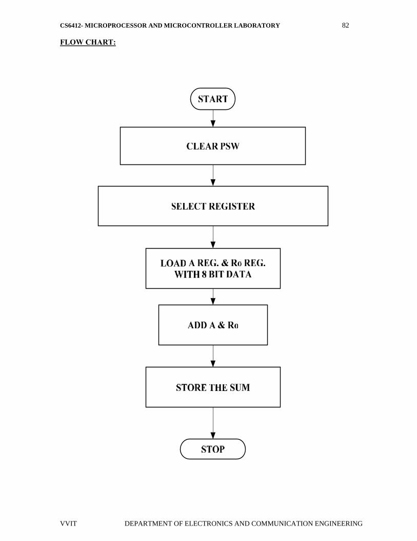
ALGORITHM:
Clear Program Status Word.
Select Register bank by giving proper values to RS1 & RS0 of PSW.
Load accumulator A with any desired 8-bit data.
Load the register R 0 with the second 8- bit data.
Add these two 8-bit numbers.
Store the result.
Stop the program.
CS6412- MICROPROCESSOR AND MICROCONTROLLER LABORATORY 82
VVIT DEPARTMENT OF ELECTRONICS AND COMMUNICATION ENGINEERING
FLOW CHART:

CS6412- MICROPROCESSOR AND MICROCONTROLLER LABORATORY 83
VVIT DEPARTMENT OF ELECTRONICS AND COMMUNICATION ENGINEERING
PROGRAM:
ADDRESS LABEL MNEMONIC OPERAND HEXCODE COMMENTS
4100 CLR C C3 Clear CY Flag
4101 MOV A,data1 74,data1 Get the data1 in
Accumulator
4103 ADDC A, #data 2 24,data2 Add the data1 with
data2
4105 MOV DPTR,#4500H 90,45,00 Initialize the memory
Location
4108 MOVX @ DPTR,A F0 Store the result in
memory location
4109 L1 SJMP L1 80,FE Stop the program
OUTPUT:
INPUT OUTPUT
MEMORYDATA
MEMORYDATA
RESULT:
Thus the 8051 ALP for addition of two 8 bit numbers is executed.
CS6412- MICROPROCESSOR AND MICROCONTROLLER LABORATORY 84
VVIT DEPARTMENT OF ELECTRONICS AND COMMUNICATION ENGINEERING
EX. NO: 21
DATE :
8 BIT SUBTRACTION
AIM:
To perform subtraction of two 8 bit data and store the result in memory.
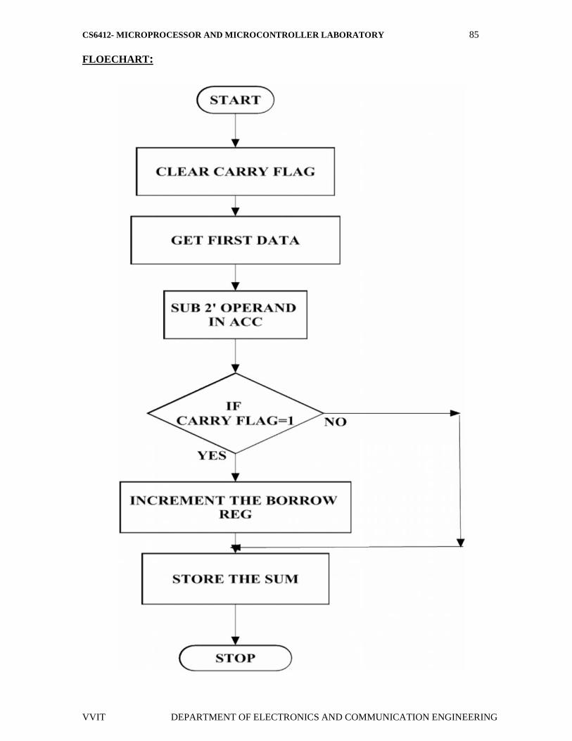
ALGORITHM:
Clear the carry flag.
Initialize the register for borrow.
Get the first operand into the accumulator.
Subtract the second operand from the accumulator.
If a borrow results increment the carry register.
Store the result in memory.
CS6412- MICROPROCESSOR AND MICROCONTROLLER LABORATORY 85
VVIT DEPARTMENT OF ELECTRONICS AND COMMUNICATION ENGINEERING
FLOECHART:
CS6412- MICROPROCESSOR AND MICROCONTROLLER LABORATORY 86
VVIT DEPARTMENT OF ELECTRONICS AND COMMUNICATION ENGINEERING
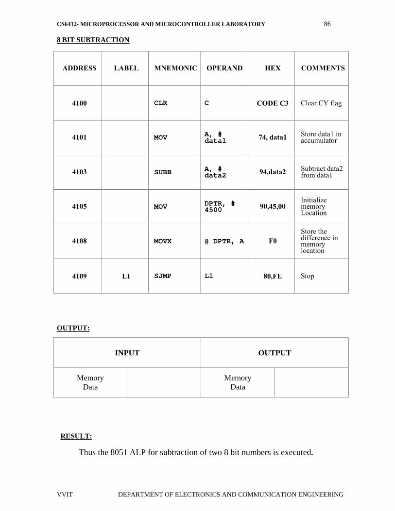
8 BIT SUBTRACTION
ADDRESS LABEL MNEMONIC OPERAND HEX COMMENTS
4100 CLR C CODE C3 Clear CY flag
4101 MOV A, #data1 74, data1 Store data1 in
accumulator
4103 SUBB A, #data2 94,data2 Subtract data2
from data1
4105 MOV DPTR, #4500 90,45,00
InitializememoryLocation
4108 MOVX @ DPTR, A F0Store thedifference inmemorylocation
4109 L1 SJMP L1 80,FE Stop
OUTPUT:
INPUT OUTPUT
MemoryData
MemoryData
RESULT:
Thus the 8051 ALP for subtraction of two 8 bit numbers is executed.
CS6412- MICROPROCESSOR AND MICROCONTROLLER LABORATORY 87
VVIT DEPARTMENT OF ELECTRONICS AND COMMUNICATION ENGINEERING
EX. NO: 22
DATE :
8 BIT MULTIPLICATION
AIM:
To perform multiplication of two 8 bit data and store the result in memory.
ALGORITHM:
Get the multiplier in the accumulator.
Get the multiplicand in the B register.
Multiply A with B.
Store the product in memory.

CS6412- MICROPROCESSOR AND MICROCONTROLLER LABORATORY 88
VVIT DEPARTMENT OF ELECTRONICS AND COMMUNICATION ENGINEERING
FLOWCHART:
CS6412- MICROPROCESSOR AND MICROCONTROLLER LABORATORY 89
VVIT DEPARTMENT OF ELECTRONICS AND COMMUNICATION ENGINEERING
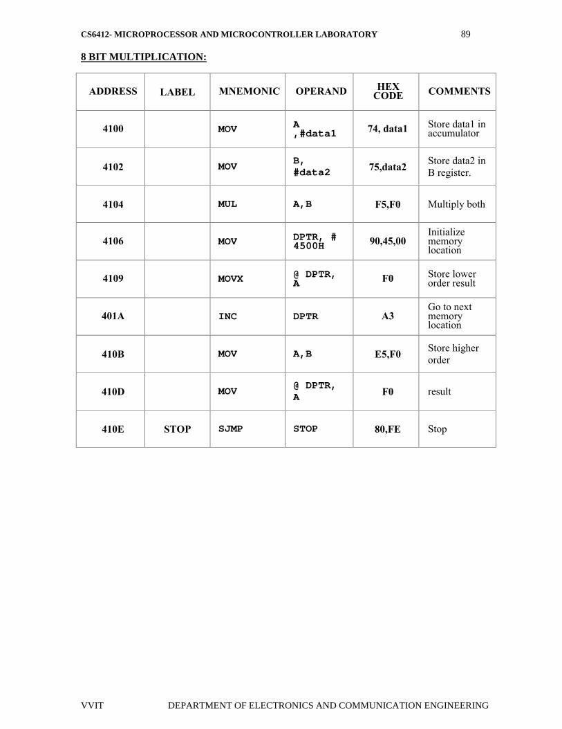
8 BIT MULTIPLICATION:
ADDRESS LABEL MNEMONIC OPERAND HEXCODE COMMENTS
4100 MOV A,#data1 74, data1 Store data1 in
accumulator
4102 MOVB,#data2 75,data2 Store data2 in
B register.
4104 MUL A,B F5,F0 Multiply both
4106 MOV DPTR, #4500H 90,45,00
Initializememorylocation
4109 MOVX @ DPTR,A F0 Store lower
order result
401A INC DPTR A3Go to nextmemorylocation
410B MOV A,B E5,F0 Store higherorder
410D MOV@ DPTR,A F0 result
410E STOP SJMP STOP 80,FE Stop
CS6412- MICROPROCESSOR AND MICROCONTROLLER LABORATORY 90
VVIT DEPARTMENT OF ELECTRONICS AND COMMUNICATION ENGINEERING
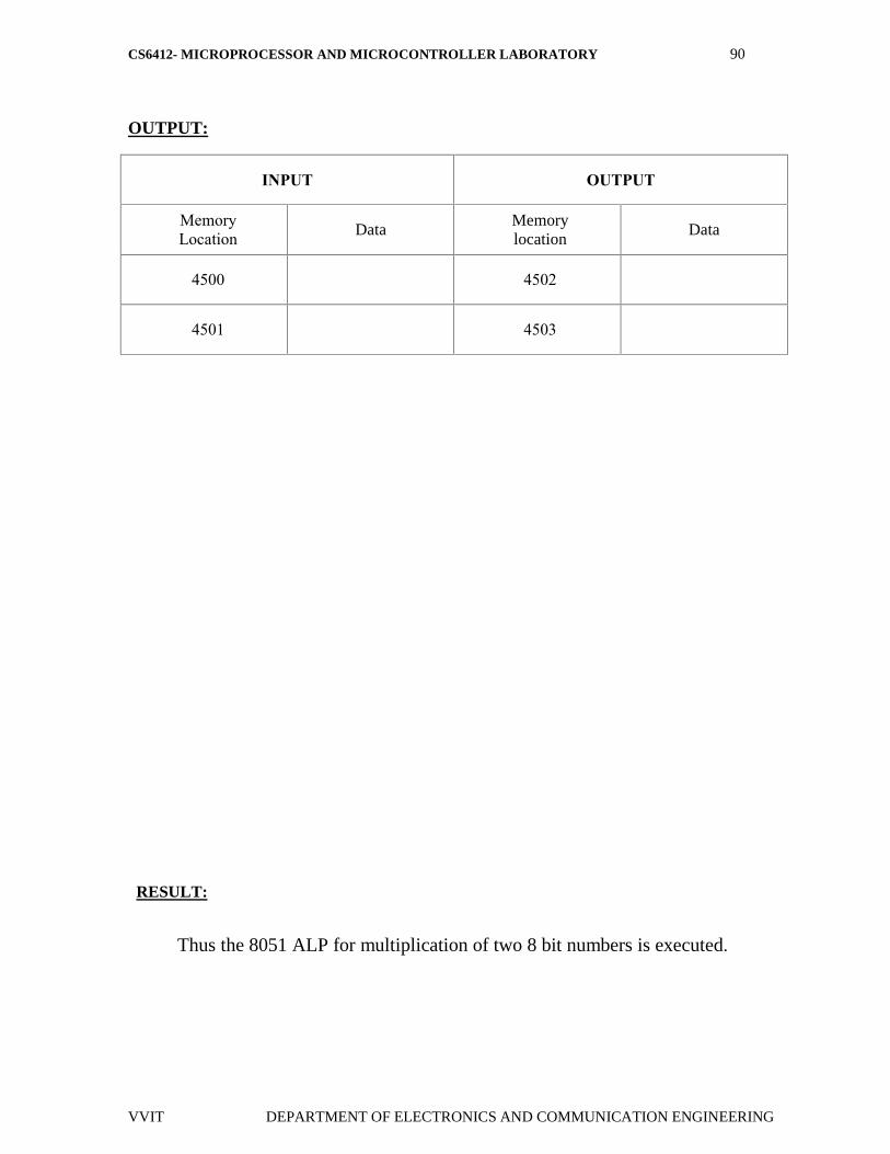
OUTPUT:
INPUT OUTPUT
MemoryLocation Data
Memorylocation
Data
4500 4502
4501 4503
RESULT:
Thus the 8051 ALP for multiplication of two 8 bit numbers is executed.
CS6412- MICROPROCESSOR AND MICROCONTROLLER LABORATORY 91
VVIT DEPARTMENT OF ELECTRONICS AND COMMUNICATION ENGINEERING
EX. NO: 23
DATE :
8 BIT DIVISION
AIM:
To perform division of two 8 bit data and store the result in memory.
ALGORITHM:
Get the Dividend in the accumulator.
Get the Divisor in the B register.
Divide A by B.
Store the Quotient and Remainder in memory.

CS6412- MICROPROCESSOR AND MICROCONTROLLER LABORATORY 92
VVIT DEPARTMENT OF ELECTRONICS AND COMMUNICATION ENGINEERING
FLOWCHART:
CS6412- MICROPROCESSOR AND MICROCONTROLLER LABORATORY 93
VVIT DEPARTMENT OF ELECTRONICS AND COMMUNICATION ENGINEERING
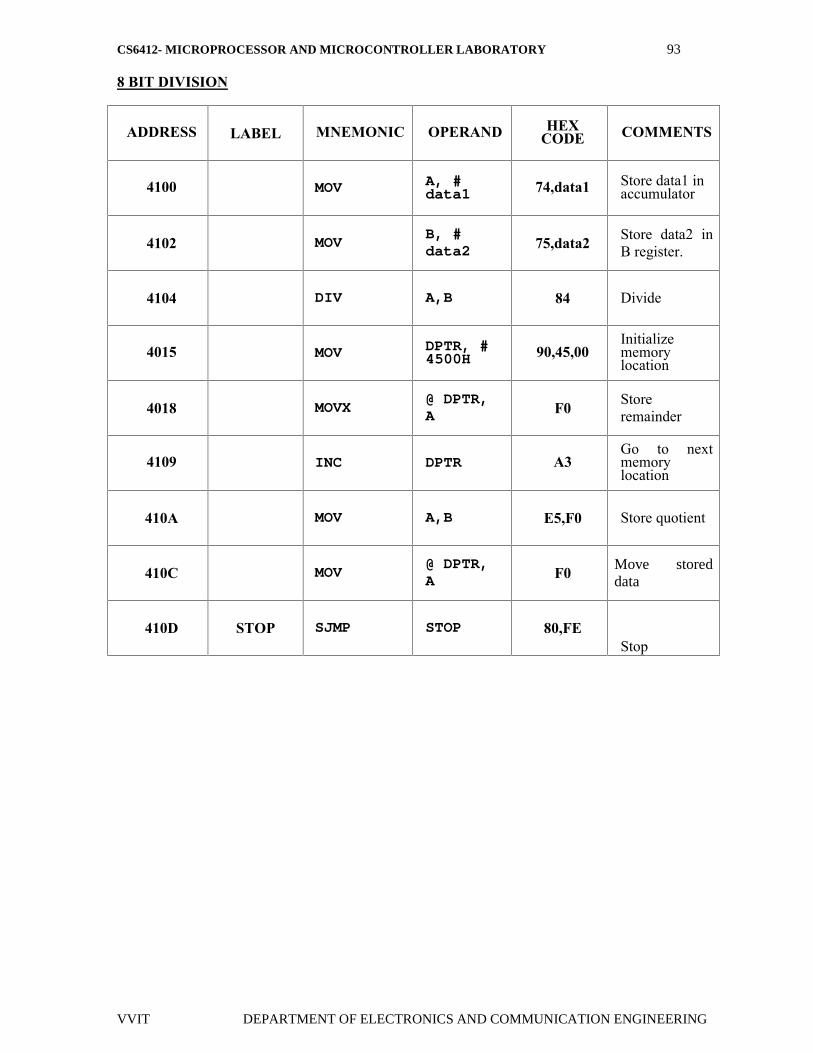
8 BIT DIVISION
ADDRESS LABEL MNEMONIC OPERAND HEXCODE COMMENTS
4100 MOV A, #data1 74,data1 Store data1 in
accumulator
4102 MOVB, #data2 75,data2 Store data2 in
B register.
4104 DIV A,B 84 Divide
4015 MOV DPTR, #4500H 90,45,00
Initializememorylocation
4018 MOVX@ DPTR,A F0 Store
remainder
4109 INC DPTR A3Go to nextmemorylocation
410A MOV A,B E5,F0 Store quotient
410C MOV@ DPTR,A F0 Move stored
data
410D STOP SJMP STOP 80,FEStop
CS6412- MICROPROCESSOR AND MICROCONTROLLER LABORATORY 94
VVIT DEPARTMENT OF ELECTRONICS AND COMMUNICATION ENGINEERING
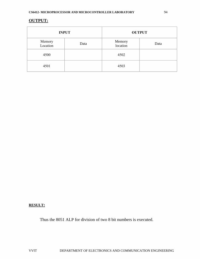
OUTPUT:
INPUT OUTPUT
MemoryLocation Data
Memorylocation
Data
4500 4502
4501 4503
RESULT:
Thus the 8051 ALP for division of two 8 bit numbers is executed.
CS6412- MICROPROCESSOR AND MICROCONTROLLER LABORATORY 95
VVIT DEPARTMENT OF ELECTRONICS AND COMMUNICATION ENGINEERING
EX. NO: 24
DATE :
SQUARE AND CUBE PROGRAM, FIND 2’S COMPLEMENT OF A
NUMBER
AIM:
To convert Square and Cube program, Find 2’s complement of a number
using 8051 micro controller
RESOURCES REQUIERED:
8051 microcontroller kit
Keyboard
Power supply
CS6412- MICROPROCESSOR AND MICROCONTROLLER LABORATORY 96
VVIT DEPARTMENT OF ELECTRONICS AND COMMUNICATION ENGINEERING
PROGRAM:
SQUARE PGM USING 8051
01 ORG 00h
02 LJMP MAIN
03 DELAYS:
04; MOV R0,#2
05 MOV TMOD, #01H
06 MOV TH0, #HIGH (-50000)
7 MOV TL0, #LOW (-50000)
8 SETB TR0
9 JNB TF0,
10CLR TF0
12; DJNZ R0,DELAY
13RET
14MAIN:
15MOV DPTR,#300H
16MOV A,#0FFH
17MOV P1,A
18BACK:
19LCALL DELAY
20MOV A,P1
21MOVC A,@A+DPTR
CS6412- MICROPROCESSOR AND MICROCONTROLLER LABORATORY 97
VVIT DEPARTMENT OF ELECTRONICS AND COMMUNICATION ENGINEERING
22;MOV P2,#00H
23;LCALL DELAY
24MOV P2,A
25SJMP BACK
26ORG 300H
27XSQR_TABLE:
28DB 0,1,4,9,16,25,36,49,64,81
29END
OUTPUT
INPUT DATA OUTPUT DATA
RESULT;
Thus the Square and Cube program, Find 2’s complement of a number is
done in 8051 microcontroller

CS6412- MICROPROCESSOR AND MICROCONTROLLER LABORATORY 98
VVIT DEPARTMENT OF ELECTRONICS AND COMMUNICATION ENGINEERING
EX. NO: 25
DATE :
UNPACKED BCD TO ASCII
AIM:
To convert BCD number into ASCII by using 8051 micro controller.
RESOURCES REQUIERED:
8051 microcontroller kit
Keyboard
Power supply

CS6412- MICROPROCESSOR AND MICROCONTROLLER LABORATORY 99
VVIT DEPARTMENT OF ELECTRONICS AND COMMUNICATION ENGINEERING
FLOWCHART:
CS6412- MICROPROCESSOR AND MICROCONTROLLER LABORATORY 100
VVIT DEPARTMENT OF ELECTRONICS AND COMMUNICATION ENGINEERING
ALGORITHM:
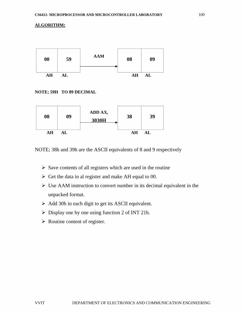
00 59AAM
08 09
AH AL AH AL
NOTE; 59H TO 89 DECIMAL
08 09ADD AX,
3030H38 39
AH AL AH AL
NOTE; 38h and 39h are the ASCII equivalents of 8 and 9 respectively
Save contents of all registers which are used in the routine
Get the data in al register and make AH equal to 00.
Use AAM instruction to convert number in its decimal equivalent in the
unpacked format.
Add 30h in each digit to get its ASCII equivalent.
Display one by one using function 2 of INT 21h.
Routine content of register.
CS6412- MICROPROCESSOR AND MICROCONTROLLER LABORATORY 101
VVIT DEPARTMENT OF ELECTRONICS AND COMMUNICATION ENGINEERING
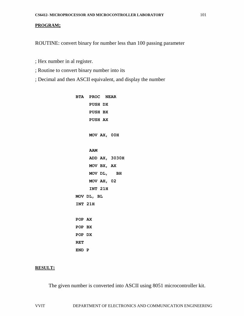
PROGRAM;
ROUTINE: convert binary for number less than 100 passing parameter
; Hex number in al register.
; Routine to convert binary number into its
; Decimal and then ASCII equivalent, and display the number
BTA PROC NEAR
PUSH DX
PUSH BX
PUSH AX
MOV AX, 00H
AAM
ADD AX, 3030H
MOV BX, AX
MOV DL, BH
MOV AH, 02
INT 21H
MOV DL, BL
INT 21H
POP AX
POP BX
POP DX
RET
END P
RESULT:
The given number is converted into ASCII using 8051 microcontroller kit.


