

Guaranteed Component Assembly w i th Round Tr ip Ana lys is
fo r Energy E f f i c ien t H igh - in tegr i ty Mu l t i - core Sys tems
Project Partners: AENSys, Aicas, Atego, Budapest University of Technology and Economics,
Critical Software, EADS, Intecs, ISEP, Maelardalens University, OTG Solutions,
SINTEF, Thales Communications & Security, The Open Group, University of Florence,
University of Padova
Every effort has been made to ensure that all statements and information contained herein are accurate, however the
Partners accept no liability for any error or omission in the same.
© 2015 Copyright in this document remains vested in the CONCERTO Project Partners.
Project Number 333053
D2.7 – Analysis and back-propagation of properties for multicore systems - Final Version
Version 1.0
3 November 2015
Final
Public Distribution
Airbus Group (EADS), INT, MDH, UNIFI, UPD

D2.7 – Analysis and back-propagation of properties for multicore systems – Final Version
Page ii Version 1.0 3 November 2015
Confidentiality: Public Distribution
DOCUMENT CONTROL
Version Status Date
0.1 Initial document structure taken from the Y2 first release of the deliv-
erable, to be reviewed and extended. First set of possible revi-
sions\extensions added.
15 Sep 2015
0.2 All sections filled. Ready for internal review 22 Oct 2015
0.3 Review by Airbus Group (EADS) and TCS 26 Oct 2015
1.0 Final version with comments addressed. New Appendix C about
MARTE usage.
03 Nov 2015

D2.7 – Analysis and back-propagation of properties for multicore systems – Final Version
3 November 2015 Version 1.0 Page iii
Confidentiality: Public Distribution
TABLE OF CONTENTS
List of Figures ................................................................................................................................................................... v
List of Tables ..................................................................................................................................................................... v
List of Abbreviations ....................................................................................................................................................... vi
Executive Summary ........................................................................................................................................................ vii
1 Introduction .............................................................................................................................................................. 1
1.1 Main changes with respect to D2.3 ..................................................................................................................... 1
2 Review of the CHESS modelling language ............................................................................................................. 1
2.1 Support for View Definition ................................................................................................................................ 2
2.2 Modelling the real time ....................................................................................................................................... 3 2.2.1 Timing annotation ....................................................................................................................................... 3 2.2.2 Real time analysis ....................................................................................................................................... 4
2.3 Modelling the dependability ............................................................................................................................... 5
2.4 Instance-level modelling ..................................................................................................................................... 6
3 CHESSML extensions – cross domain .................................................................................................................... 8
3.1 System Model ...................................................................................................................................................... 8 3.1.1 Data flow .................................................................................................................................................... 8 3.1.2 Socio-technical systems .............................................................................................................................. 8
3.2 Component Model ............................................................................................................................................... 9 3.2.1 Data flow .................................................................................................................................................... 9 3.2.2 Inter-components bindings scenarios .......................................................................................................... 9 3.2.3 Hierarchical Components .......................................................................................................................... 10 3.2.4 Events ....................................................................................................................................................... 11 3.2.5 HW Abstraction Component ..................................................................................................................... 12
3.3 Operational Modes ........................................................................................................................................... 12
3.4 Dependability\Safety Model .............................................................................................................................. 13 3.4.1 The new CHESS dependability profile ..................................................................................................... 13 3.4.2 Modelling Criticality ................................................................................................................................. 14
3.5 Platform and Allocation Models (Deployment Model) ..................................................................................... 16 3.5.1 Modelling allocations for each operational mode ..................................................................................... 16
3.6 Extra functional properties for operational modes ........................................................................................... 17
3.7 Multi-cores processors ..................................................................................................................................... 17
3.8 Run-time Monitoring and Verification .............................................................................................................. 18
3.9 Partition Modelling ........................................................................................................................................... 19
3.10 Analysis model .................................................................................................................................................. 21
3.11 Advanced support for Sporadic operation ........................................................................................................ 21
4 CHESSML modification –domain specific ........................................................................................................... 22
4.1 Petroleum .......................................................................................................................................................... 22
4.2 Automotive ........................................................................................................................................................ 22
4.3 Avionics............................................................................................................................................................. 24 4.3.1 Functional Partitions ................................................................................................................................. 24 4.3.2 ARINC Processes ..................................................................................................................................... 24 4.3.3 Restriction on the deployment .................................................................................................................. 28
5 Coverage of CONCERTO metamodel derived requirements ............................................................................. 28

D2.7 – Analysis and back-propagation of properties for multicore systems – Final Version
Page iv Version 1.0 3 November 2015
Confidentiality: Public Distribution
6 Conclusion ............................................................................................................................................................... 34
7 References ................................................................................................................................................................ 35
A. An introduction to the CHESSML profile ........................................................................................................ 35
B. CONCERTO Dependability Profile .................................................................................................................. 40
B.1 Stereotypes ............................................................................................................................................................. 41
B.2 Notes about the current implementation ................................................................................................................ 53 B.2.1 Deprecated stereotypes .................................................................................................................................... 53 B.2.2 Renamed Stereotypes ...................................................................................................................................... 53 B.2.3 About the FPTCSpecification ......................................................................................................................... 54
C. About MARTE usage in the CHESSML .......................................................................................................... 55
D2.7 – Analysis and back-propagation of properties for multicore systems – Final Version
3 November 2015 Version 1.0 Page v
Confidentiality: Public Distribution
LIST OF FIGURES
Figure 1: MARTE RtSpecification CHESS extensions ...................................................................................................... 4 Figure 2: CSD and its corresponding “composite instance model”, source UML specification ......................................... 7 Figure 3: Sequence diagram representing inter-component bindings ............................................................................... 10 Figure 4: Modelling Signals ............................................................................................................................................. 11 Figure 5: Modelling Operational Modes (source MARTE spec.) ..................................................................................... 13 Figure 6: Extension for criticality level modelling support .............................................................................................. 15 Figure 7: Criticalities specification ................................................................................................................................... 16 Figure 8: Criticalities Interface Specification ................................................................................................................... 16 Figure 9: modelling Allocations constrained to OperationalModes ................................................................................. 17 Figure 10: MARTE HWProcessor stereotype .................................................................................................................. 18 Figure 11- RunTimeSupport stereotype ............................................................................................................................ 19 Figure 12: Using MARTE MemoryPartition .................................................................................................................... 20 Figure 13: CHRtSpecification extension for sporadic operations ..................................................................................... 22 Figure 14: CHESS stereotypes for modelling redundant ASIL decomposition ................................................................ 23 Figure 15: Modelling Redundant Decomposition in CHESS ........................................................................................... 24 Figure 16: CHESS profile for ARINC processes .............................................................................................................. 25 Figure 17: CHESS model and views predefined structure ................................................................................................ 35 Figure 18: Interfaces ......................................................................................................................................................... 35 Figure 19: ComponentTypes ............................................................................................................................................ 35 Figure 20: ComponentType‟s provided and required ports .............................................................................................. 36 Figure 21: CHESS ComponentImplementation ................................................................................................................ 36 Figure 22: Intra-component binding ................................................................................................................................. 37 Figure 23: CHESS ComponentImplementation instances ................................................................................................ 37 Figure 24: CHESS timing annotation ............................................................................................................................... 38 Figure 25: CHESS Instance Model ................................................................................................................................... 38 Figure 26: CHESS deployment model .............................................................................................................................. 39 Figure 27: Dependability information annotated HW components .................................................................................. 39 Figure 28: SBA analysis context ...................................................................................................................................... 39 Figure 29: FPTC specification .......................................................................................................................................... 40 Figure 30: Results of the FPTC analysis........................................................................................................................... 40 Figure 31: Proposal for the CONCERTO dependability conceptual model. .................................................................... 41 Figure 32: MARTE HLAM::RtSpecification and HLAM::RTFeature CHESSML extensions........................................ 57
LIST OF TABLES
Table 1 - WP4, WP3 cross domain “metamodel” reqs and their coverage at M30 .......................................................... 28 Table 2 - WP4, WP3 domain specific “metamodel” reqs and their coverage at M18 ...................................................... 33

D2.7 – Analysis and back-propagation of properties for multicore systems – Final Version
Page vi Version 1.0 3 November 2015
Confidentiality: Public Distribution
LIST OF ABBREVIATIONS
ARINC Aeronautical Radio INCorporated
ASIL Automotive Safety Integrity Level
CHESSML CHESS Modelling Language
CSD Composite Structure Diagram
DSL Domain Specific Language
FLA Failure Logic Analysis
FPTC Failure Propagation and Transformation Calculus
IMA Integrated Modular Avionics
PIM Platform Independent Model
PSM Platform Specific Model
QoS Quality of Service
SBA State-Based Analysis

D2.7 – Analysis and back-propagation of properties for multicore systems – Final Version
3 November 2015 Version 1.0 Page vii
Confidentiality: Public Distribution
EXECUTIVE SUMMARY
This deliverable is the M30 update of its D2.3 predecessor and reports on the work
conducted in WP2 as final definition of the modelling language capable to express
system, software and hardware multi-core architectures, together with non-functional
properties for analysis and back-annotation.
The findings discussed in this document rely upon the understanding of industrial
requirements captured in WP1 and in particular upon the corresponding elaborations
performed in WP2, WP3 and WP4.
This document considers the results of the CHESS project as baseline and then
elaborates upon the extensions that have been defined to satisfy the CONCERTO
project requirements.


D2.7 – Analysis and back-propagation of properties for multicore systems – Final Version
3 November 2015 Version 1.0 Page 1
Confidentiality: Public Distribution
1 INTRODUCTION
This deliverable is the M30 update of its D2.3 predecessor and describes the
modifications required for the CHESS modelling language to support the CONCERTO
needs for what regards the modelling, analysis and back propagation of the analysis
results. In particular, results coming from WP3 and WP4 have been taken into account.
The structure of the document is the following: first the review of the CHESS modelling
language, as resulting from the CHESS project, is addressed in section 2; then in
sections 3 and 4 the extensions of the CHESS modelling language for the cross and
specific domain needs respectively are discussed. The coverage of the CONCERTO
requirements with respect to the updated CHESS modelling language (as presented in
this document) is provided in section 5.
1.1 MAIN CHANGES WITH RESPECT TO D2.3
With respect to D2.3, the following sections\topics have been created or significantly
updated\reviewed:
2 Review of the CHESS modelling language (updated)
3.2.5 HW Abstraction Component (new)
3.4.2 Modelling Criticality (new)
3.7 Multi-cores processors (new)
3.8 Run-time Monitoring and Verification (new)
3.9 Partition Modelling (updated) (section 3.8 in D2.3)
3.11 Advanced support for Sporadic operation (new)
4.2 Automotive (updated)
4.3 Avionics (new)
5 Coverage of CONCERTO metamodel derived requirements (updated)
B CONCERTO Dependability Profile (updated)
C About MARTE usage in the CHESSML (new)
2 REVIEW OF THE CHESS MODELLING LANGUAGE
The CHESS modelling language (CHESSML) is considered as the baseline for the
CONCERTO needs. This section reviews the current version of the CHESSML, i.e. the
one resulting from the CHESS project, in order to better identify a more stable and
suitable baseline to be adopted in CONCERTO.

D2.7 – Analysis and back-propagation of properties for multicore systems – Final Version
Page 2 Version 1.0 3 November 2015
Confidentiality: Public Distribution
The CHESSML specification, as metamodel\UML profile, is described in the CHESS
deliverable D2.3.2 [CHESSD232].
Basically the CHESSML restricts and extends the SysML, UML and MARTE OMG
standards to support:
view definition,
modelling of PIM entities,
modelling of the hardware platform,
modelling of timing related information (at PIM and PSM level),
modelling of dependability information (at PIM and platform level),
modelling of analysis scenario,
modelling of PSM entities,
back propagation of analysis results (at PSM and PIM level).
The reader can refer to annex A for a quick introduction to the CHESSML illustrating
the aforementioned support.
In the remainder of this document the term component type is used to refer to a
classifier of a set of component instances, in the sense of the object-oriented paradigm,
while the terms ComponentType and ComponentImplementation are used to refer the
corresponding entities (i.e. stereotypes of the UML Component) defined in the CHESS
component model (see CONCERTO D2.2).
2.1 SUPPORT FOR VIEW DEFINITION
In CHESSML a view corresponds to a stereotyped package, i.e. a UML container
allowed to own all the entities that belong to the given view. It is worth remembering
that a view-package can be defined as the sum of distinct sub-views, the latter acting
upon the same package of the parent view; e.g. this is the case for the CHESS
component view-package which is actually the overlapping of two distinct sub-views:
the functional and extra functional views.
Regarding the support for views definition in CHESSML, no extension has been done
in CONCERTO regarding UML support.
One possible solution identified in CONCERTO regards the definition of a dedicated
meta-model for views specification1; in particular, for each view, the meta-model
should allow to formalize the permission rules (e.g. read-only, read-write) to be applied 1 View specification is also known in literature as viewpoint. E.g. from the SysML: “A Viewpoint is a specification of
the conventions and rules for constructing and using a view for the purpose of addressing a set of stakeholder con-
cerns…”

D2.7 – Analysis and back-propagation of properties for multicore systems – Final Version
3 November 2015 Version 1.0 Page 3
Confidentiality: Public Distribution
at modelling-time on the UML entities and, more in general, on the entities of a given
domain specific language (DSL, e.g. implemented as UML profile), as defined by the
view specification itself. The meta-model should be implemented in Eclipse and a
framework should be developed on top of it to offer a DSL-independent support for
views definition and usage; the framework should be designed to be integrated with the
Eclipse Papyrus UML editor. Due to project priorities, derived according to the end-
user requirements, and resources, the development of the aforementioned support has
not been planned yet.
2.2 MODELLING THE REAL TIME
2.2.1 Timing annotation
Regarding real time modelling and back-propagation support, CHESSML basically
relies on the usage of a subset of the MARTE language which allows the timing
decoration of component‟s ports at PIM level. MARTE, in particular the
RtSpecification2 stereotype, has been extended in CHESS (Figure 1) to support real-
time annotation of operations exposed through provided ports at component instance
level. In fact MARTE allows to attach real time information like thread activation
pattern (e.g. sporadic, periodic), deadline to a given operation of a component type,
while timing information is proper of (and as to be differentiated for) each single
component instance. The aforementioned limitation of MARTE was reported to the
MARTE OMG team3 and it will be fixed in the next version of the MARTE OMG
release.
See Annex C for a more detailed explanation about usage of the MARTE entities in
CHESS.
2 Defined in the MARTE High-Level Application Modeling (HLAM) sub-profile
3 OMG Issue 15166

D2.7 – Analysis and back-propagation of properties for multicore systems – Final Version
Page 4 Version 1.0 3 November 2015
Confidentiality: Public Distribution
Figure 1: MARTE RtSpecification CHESS extensions
In CHESSML the decoration of component‟s operations exposed through provided
ports makes it possible to address operations having public visibility only; in fact only
public operations are visible through a provided port.
In CONCERTO, in order to support some specific request from domains like avionics
(see 4.3.2), the CHESSML CHRtSpecification has been extended to allow the
decoration of private operations for a given component instance; in particular according
to the CONCERTO component model definition (see CONCERTO D2.6)
CHRtSpecification can only be used to decorate private operations as protected or
unprotected.
2.2.2 Real time analysis
Another MARTE customization available in CHESS regards the way analysis results
are available in the model (by back-propagation). The MARTE profile makes a clear
distinction about how HW, SW resources and the information related to a given analysis
are modelled, and uses different stereotypes for these different aspects4. In CHESS
4 MARTE stereotypes for modeling of application programming interfaces of software multi-tasking platforma are
available in the Software Resource Modeling (SRM) sub-profile. Stereotypes focused on modeling hardware platform
D2.7 – Analysis and back-propagation of properties for multicore systems – Final Version
3 November 2015 Version 1.0 Page 5
Confidentiality: Public Distribution
some parts of this information have been collapsed into the extended RtSpecification
stereotype; in fact the latter is used to provide timing properties of the SW operations-
resources (e.g. their activation kind, like periodic, sporadic, and its deadline) and to
attach data coming from the analysis (e.g. the worst case response time and blocking
time for the given operation) (see Annex A); this was done in CHESS because MARTE
does not allow to have information about a given analysis directly attached to port-
operation (i.e. where the RtSpecification applies).
In order to provide a better compliance with the MARTE standard, CONCERTO has
changed the way real time information resulting from the analysis are back propagated
in CHESS. In CHESS, in order to perform timing analysis, a PSM model is
automatically generated starting from the PIM user-level model; basically the PSM
represents the PIM model bounded to a given computational model. In the PSM,
MARTE stereotypes (from the Software Resourece Modeling sub-profile) are used to
provide the definition of tasks and shared resources; moreover the MARTE stereotypes
concerning schedulability analysis (from the Schedulability Analysis Modeling sub-
profile) are used as well.
In CONCERTO the back propagation of the analysis results is applied to the PSM level
entities only; at the same time traceability information between the PSM and the PIM
related entities are generated and stored in the model. Then the back propagation of the
analysis results to the PIM model is derived on demand by querying the model, in
particular by using the stored traceability links.
With the solution depicted above the analysis contexts and results can be modelled
separately from the SW\HW resources; concerning the CHESSML profile, it has been
possible to remove the attributes resulting from the analysis from the CHRtSpecification
(in particular the response time and the blocking time), allowing to have a strict
compliance with the MARTE standard.
To allow the user to easily retrieve and navigate the information related to the analysis
results, a dedicated tab view has been developed in CONCERTO; the analysis results
view shows all the analysis results associated to the selected analysis context, allowing
to navigate the provided information (e.g. the given sporadic\periodic operation) from
the view and the model explorer and diagram with hyperlinks (see CONCERTO D2.6
deliverable, section 3.1.5.1.1).
2.3 MODELLING THE DEPENDABILITY
Regarding dependability, CHESSML comes with a dedicated dependability profile
[CHESSD232]; the parts of the dependability profile useful to represent error models,
state-based and failure propagation information has been reviewed and extended in
CONCERTO according to the results coming from the WP3 and documented in the
CONCERTO D3.3 deliverable. The other constructs available in the CHESS
dependability profile have not been considered in CONCERTO given that they are out
of scope.
are available in the Hardware Resource Modeling (HRM) MARTE sub-profile. Stereotyped intended specifically for
schedulability analysis are available in the Schedulability Analysis Modeling (SAM) MARTE sub-profile.
D2.7 – Analysis and back-propagation of properties for multicore systems – Final Version
Page 6 Version 1.0 3 November 2015
Confidentiality: Public Distribution
The elaboration about the extensions of the dependability profile is provided in section
3.4.
2.4 INSTANCE-LEVEL MODELLING
The CHESSML resulting from the CHESS project makes use of the UML composite
structure diagram (CSD) to model instances and extra functional information for them;
there can be some limitation while using CSDs to model instances, especially if
hierarchies of instances, i.e. instances owning sub-instances, have to be considered,
together with its ports and extra functional decoration5. This limitation is even more
relevant in CONCERTO where decomposition of components and hierarchical
instances and their extra functional annotation are considered.
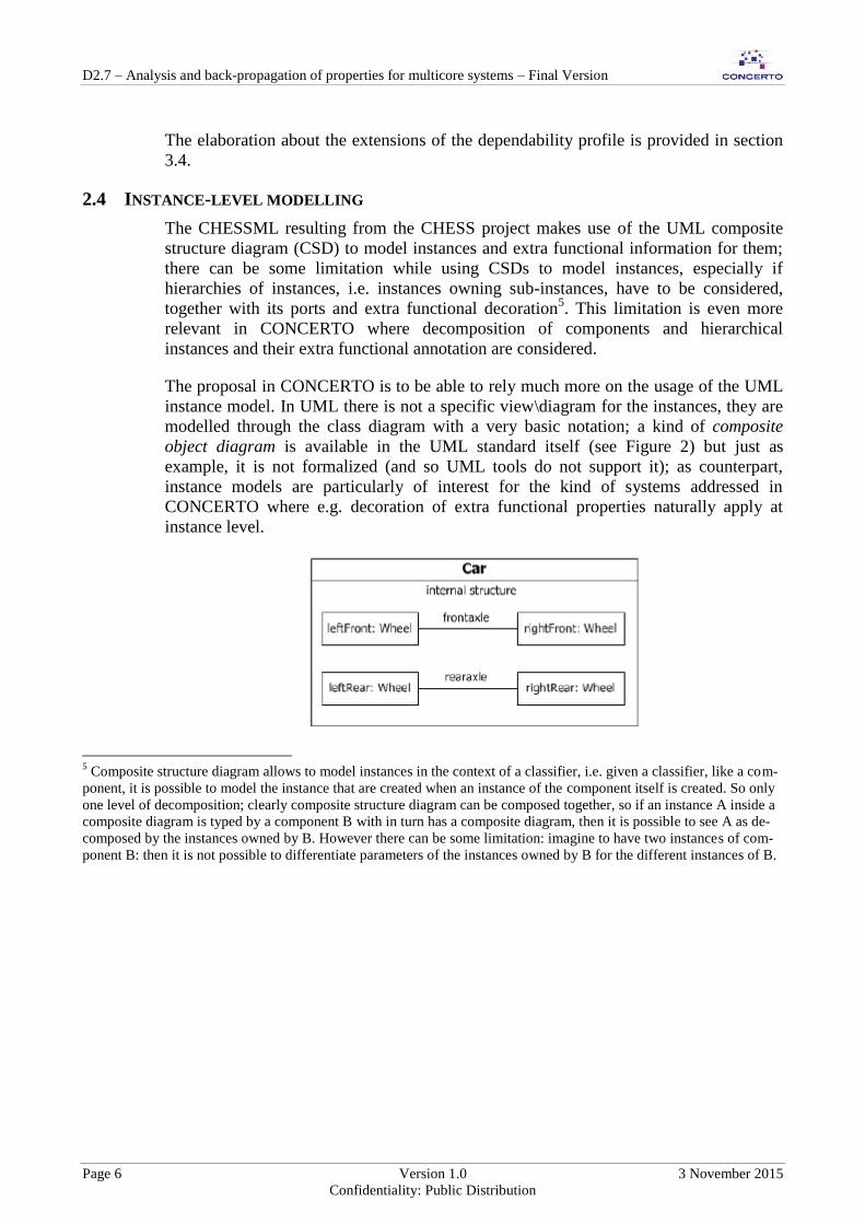
The proposal in CONCERTO is to be able to rely much more on the usage of the UML
instance model. In UML there is not a specific view\diagram for the instances, they are
modelled through the class diagram with a very basic notation; a kind of composite
object diagram is available in the UML standard itself (see Figure 2) but just as
example, it is not formalized (and so UML tools do not support it); as counterpart,
instance models are particularly of interest for the kind of systems addressed in
CONCERTO where e.g. decoration of extra functional properties naturally apply at
instance level.
5 Composite structure diagram allows to model instances in the context of a classifier, i.e. given a classifier, like a com-
ponent, it is possible to model the instance that are created when an instance of the component itself is created. So only
one level of decomposition; clearly composite structure diagram can be composed together, so if an instance A inside a
composite diagram is typed by a component B with in turn has a composite diagram, then it is possible to see A as de-
composed by the instances owned by B. However there can be some limitation: imagine to have two instances of com-
ponent B: then it is not possible to differentiate parameters of the instances owned by B for the different instances of B.

D2.7 – Analysis and back-propagation of properties for multicore systems – Final Version
3 November 2015 Version 1.0 Page 7
Confidentiality: Public Distribution
Figure 2: CSD and its corresponding “composite instance model”, source UML specification
CONCERTO allows decoration of the UML instance model with extra functional
properties. A specific InstanceView has been implemented on top the CHESS editor by
using a query driven approach; in this way it is possible to render the instances in a
hierarchical representation, allowing the modeller to easily navigate the instance model
and provide properties for the instances, as alternative to the usage of the CSDs.
So the modelling steps to be performed in order to complete the design in the extra
functional dimension are:
1. Create components (first ComponentType and then ComponentImplementation).
2. Create components CSDs for ComponentImplementation.
3. For the extra functional properties that can be expressed at this level, e.g., the
dependability error model: attach extra functional information to the components
and internals (the latter modelled in the CSDs)
4. Create the instance model starting from what has been modelled with the
component diagrams and their CSD‟s, which can be done automatically in
CHESS by using a dedicated command.
5. Use the instance model view to attach extra functional information for the
instances or to override the extra functional properties eventually modelled in
the step 3, if needed.
In order to support step 5, the modelling language constructs used in CHESSML to
model extra functional annotations at component level or in the CSD have to be made
available in the instance model view.
Note that this support is particularly useful to complete the modelling of software
component for what regards extra functional annotations, but it can also be adopted in
the system view and platform specification view if useful to model blocks and hardware
components properties at instance level.

D2.7 – Analysis and back-propagation of properties for multicore systems – Final Version
Page 8 Version 1.0 3 November 2015
Confidentiality: Public Distribution
3 CHESSML EXTENSIONS – CROSS DOMAIN
This section addresses the cross-domain model-level support added to the CHESSML to
support the CONCERTO needs.
3.1 SYSTEM MODEL
The modelling support discussed in this section is offered through the System View,
which basically reuses and tailors the SysML standard.
3.1.1 Data flow
SysML support to the modelling of data flow is introduced in CHESSML. This is to
allow modelling of data-flow at system level, e.g. useful to enable expression of
dependability properties and to allow dependability analysis at system level.
3.1.2 Socio-technical systems
Extensions to the CHESSML are introduced to address the modelling of socio-technical
systems, the latter discussed in CONCERTO deliverable D3.2.
To enable the modelling of socio-entities, two additional kinds of composite
components are introduced in the CHESSML: human and organizational. According to
the CONCERTO FLA:
human beings are modelled as composite components comprising their sensor-
like and actuator-like functionalities (as atomic components); human failures can
be represented as an internal component, named accordingly to the category.
Input ports of the human composite component should be connected to
appropriate input port of the logical (or sensor-like) component, and the output
of the action-related component should be connected to the output port of the
human component. Several logical components can be connected to action-
related component, and only one action-related component should be allowed
for one human component.
Organizational composite components should be connected to human composite
components using appropriate ports to capture organizational influences on
human behaviour. Human composite components are then connected to
technical (composite) component.
So the following stereotypes are added in the CHESSML in the system view (as
specialization of the SysML Block entity):
Human
Organizational
Technical.
As documented in D3.2, CONCERTO FLA is based upon the CHESS Failure
Propagation and Transformation Calculus (FPTC) formalisms and analysis.

D2.7 – Analysis and back-propagation of properties for multicore systems – Final Version
3 November 2015 Version 1.0 Page 9
Confidentiality: Public Distribution
To allow failure logic analysis to be applied to socio-technical systems, the CHESS
language constructs already available to support FPTC expressions for software and
hardware components become also applicable to the socio-technical systems entities. In
detail, FPTC can be used to assign a FPTC expression to humans, organizational and
technical blocks and related sub-blocks, while FPTCSpecification can be used to model
a given failure (late, early, omission, etc.) in input or output to a given block‟s port.
Furthermore, as required by the CONCERTO FLA, the application of FPTC is extended
to connectors, to allow modelling of failure of blocks interactions, and to block and
connector instances, to allow the refinement of FPTC specification at block instance
level.
3.2 COMPONENT MODEL
This section addresses the new modelling features introduced in CHESS regarding the
CHESS component model (see CONCERTO D2.6 deliverable).
3.2.1 Data flow
Data flow is introduced in the ComponentView as supported by MARTE through the
FlowPort entity6 (similar to the SysML support available in the SystemView). In
CHESSML FlowPorts are not allowed to be decorated with timing information. Data
flow in the component model is introduced to enrich the support for functional and
dependability modelling. For example, in a preliminary phase of the software design -
where typically dependability analysis applies - only the data flow can be available for
the entities under design, while the provided and required interfaces and service ports
(i.e. ports providing and requiring operations) are still to be defined. In this case the
usage of flow ports can be used to allow preliminary dependability\safety analysis, like
failure propagation, without the need to introduce and consider provided and required
interfaces\ports for the components.
3.2.2 Inter-components bindings scenarios
Inter-components bindings are functional collaboration scenarios, i.e. call operations
flows between interacting component instances.
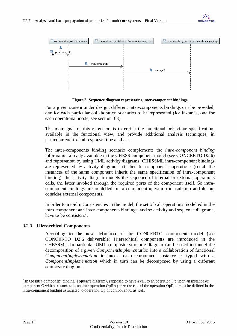
UML sequence diagrams are introduced in CHESSML to support the modelling of
inter-components bindings; see Figure 3 for an example, where component instances are
represented together with the sequence of the operations calls between them.
6 Available in the MARTE Generic Component Model (GCM) sub-profile
D2.7 – Analysis and back-propagation of properties for multicore systems – Final Version
Page 10 Version 1.0 3 November 2015
Confidentiality: Public Distribution
Figure 3: Sequence diagram representing inter-component bindings
For a given system under design, different inter-components bindings can be provided,
one for each particular collaboration scenarios to be represented (for instance, one for
each operational mode, see section 3.3).
The main goal of this extension is to enrich the functional behaviour specification,
available in the functional view, and provide additional analysis techniques, in
particular end-to-end response time analysis.
The inter-components binding scenario complements the intra-component binding
information already available in the CHESS component model (see CONCERTO D2.6)
and represented by using UML activity diagrams. CHESSML intra-component bindings
are represented by activity diagrams attached to component‟s operations (so all the
instances of the same component inherit the same specification of intra-component
binding); the activity diagram models the sequence of internal or external operations
calls, the latter invoked through the required ports of the component itself. So intra-
component bindings are modelled for a component-operation in isolation and do not
consider external components.
In order to avoid inconsistencies in the model, the set of call operations modelled in the
intra-component and inter-components bindings, and so activity and sequence diagrams,
have to be consistent7.
3.2.3 Hierarchical Components
According to the new definition of the CONCERTO component model (see
CONCERTO D2.6 deliverable) Hierarchical components are introduced in the
CHESSML. In particular UML composite structure diagram can be used to model the
decomposition of a given ComponentImplementation into a collaboration of functional
ComponentImplementation instances: each component instance is typed with a
ComponentImplementation which in turn can be decomposed by using a different
composite diagram.
7 In the intra-component binding (sequence diagram), supposed to have a call to an operation Op upon an instance of
component C which in turns calls another operation OpReq; then the call of the operation OpReq must be defined in the
intra-component binding associated to operation Op of component C as well.

D2.7 – Analysis and back-propagation of properties for multicore systems – Final Version
3 November 2015 Version 1.0 Page 11
Confidentiality: Public Distribution
3.2.4 Events
Events, as supported by the CONCERTO component model, are introduced in the
CHESS modelling language by using the UML Signal. UML Signals supports
generalization and sub-typing (i.e. it is possible to have hierarchies of events) and they
can either carry parameters or be parameter-less, as required by the CONCERTO
component model. Moreover, UML defines that the sender of a Signal will not block
waiting for a reply but continue execution immediately which is compliant with the
constraint of the CONCERTO component model which does not allows sender-side
operations to be blocking.
The possibility to have MARTE output/input FlowPorts typed by a single Signal is
introduced in the CHESSML for the ComponentType and ComponentImplementation8,
so to model the emission/reception of events, i.e. what is called in the CONCERTO
component model event emitter/receiver ports. In addition, out flow port can be bound
to multiple in flow ports (or even none), as many as the components that are interested
in the notification.
The information about the event that can be emitted by the implementation of a given
operation is modelled in the activity diagram representing the intra-component binding
of the operation itself; in particular the UML SendSignalAction has to be used in the
activity diagram.
To model that a ComponentType or ComponentImplementation can react to a given
event, the UML Reception construct has to be attached to the component; the Reception
allows specifying the behaviour of the component to be processed when the given signal
arrives.
Figure 4 shows the modelling of Signal and Reception in UML; in particular Receptions
is shown in the Component‟s compartment using the same notation as for Operations
with the keyword «signal».
Figure 4: Modelling Signals
As additional constraint from the CONCERTO component model, the operation tagged
with Receipt, can only be marked protected or unprotected in the extra-functional view.
8 The same support can be added in the system view for the block entities if needed.

D2.7 – Analysis and back-propagation of properties for multicore systems – Final Version
Page 12 Version 1.0 3 November 2015
Confidentiality: Public Distribution
3.2.5 HW Abstraction Component
In CONCERTO the CHESS notion of ComponentImplementation has been extended
with the concept\stereotype of HWAbstractionComponentImpl.
HWAbstractionComponentImpl allows the representation of a functional component
which encapsulates the dependencies of the application on specific hardware
components, like sensors or actuators.
HWAbstractionComponentImpl stereotype comes with a property typed with the
HWResource of MARTE which can be used to set the hardware resource (e.g.
HWSensor, HWActuator, HWComputingResource) of which the
HWAbstractionComponentImpl represents the abstraction.
In CONCERTO, the HWAbstractionComponent Impl stereotype has been used in
particular to provide a more strict compatibility with the AUTOSAR component model
(see CONCERTO D2.6 deliverable); however it is safe to state that
HWAbstractionComponentImpl is a cross domain stereotype.
3.3 OPERATIONAL MODES
Operational modes are introduced in the CHESSML. As stated in the MARTE
specification:
“An operational mode can represent different things:
An operational system (or subsystem) state that is managed by reconfiguration
mechanisms (e.g., fault-tolerance management middleware) according to fault
conditions.
A state of system operation with a given level of QoS that can be handled by
resource management infrastructures (e.g., middleware that assign resources at
run time according to load demand, timing constraints, or resource usage).
A phase of a system operation (e.g., starting, stopping, launching, in a mission-
critical aerospace system).”
Operational modes can be defined for the given system under design by using MARTE
stereotypes (defined in the CoreElements sub-profile), and in particular the stereotyped
modeBehaviour state machine, together with mode states and mode transitions (see in
Figure 5). Mode transitions can be added in the state machine in response to an Event
(see section 3.2.4) to model how a given change of mode is activated in the system.
The modeBehaviour state machine can be defined at system, component or hardware
level. Currently in CHESSML we assume that only one modeBehaviour can be
provided for a given CHESS model.

D2.7 – Analysis and back-propagation of properties for multicore systems – Final Version
3 November 2015 Version 1.0 Page 13
Confidentiality: Public Distribution
Figure 5: Modelling Operational Modes (source MARTE spec.)
3.4 DEPENDABILITY\SAFETY MODEL
The modelling support discussed in this section is offered through the different
dependability views available in the system, component and deployment views (see
CONCERTO D2.5 deliverable about views).
3.4.1 The new CHESS dependability profile
According to result of WP3, the needs for modifications of the CHESS dependability
profile have been identified in order to:
improve the support for dependability modelling and analysis needs,
improve the integration between the two analysis techniques of interest in
CONCERTO, namely “State-Based Analysis” (SBA in the following) and
“Failure Logic Analysis” techniques (FLA in the following).
The proposed extensions are based on the following requirements coming from
CONCERTO D3.2 (see D3.2 for a deeper elaboration):
In CHESSML it shall be possible to define different (custom) failure
classifications, to be used in different models, or for different components.
In the current CHESSML failure classifications are associated with component
ports, i.e., the failures that are assumed to occur on that port can be specified.
Ports connected together by a connector should use the same classification with
respect to failures.
In CHESSML, it should be possible to use annotations for state-based and for
failure logic analysis together

D2.7 – Analysis and back-propagation of properties for multicore systems – Final Version
Page 14 Version 1.0 3 November 2015
Confidentiality: Public Distribution
More in general, in CONCERTO ML, it should be possible to define the failure
behaviour of a component at different levels of details:
o No annotations
The component does never fail spontaneously (i.e., no internal
faults). If an incoming failure is received from another
component, then it is “transmitted” as it is.
o FLA annotations only
The component does never fail spontaneously (i.e., no internal
faults). If an incoming failure is received from another
component, then it is “transmitted” according to FLA rules.
o SBA annotations (failure rate/repair rate)
o SBA annotations + FLA annotations
o Error Model
In the error model it shall be possible to define several ErrorStates, which define
the behaviour of the component different from the nominal Healthy state (the
InitialState).
In the error model the distinction between Error and FailureMode as in the
current CHESSML is no more needed. For any ErrorState it shall be possible to
define which failure mode affects the ports owned by the component.
The reader can refer to Annex B for an elaboration of the implementation of the
aforementioned requirements, included in the CHESSML as replacement\enhancement
of the previous CHESS dependability profile.
3.4.2 Modelling Criticality
The new dependability profile allows to model criticality (e.g. as ASIL9) decoration for:
Requirements
System level components (i.e. SysML Blocks)
Software component operations
Hardware Components
The modelling of criticalities has been particularly useful in CONCERTO to provide
support for validation of criticalities constraints (see CONCERTO D4.11 deliverable);
e.g. support at model level for ASIL inheritance, propagation and decomposition check, 9 Automotive Safety Integrity Level (ASIL) is a risk classification scheme defined by the ISO 26262 - Functional Safety
for Road Vehicles standard.

D2.7 – Analysis and back-propagation of properties for multicore systems – Final Version
3 November 2015 Version 1.0 Page 15
Confidentiality: Public Distribution
e.g. the latter as defined by the functional safety ISO 26262 automotive standard has
been implemented (analogous support can be provided for other domain).
Picture below provides a sketch of the extensions introduced in the CHESSML as part
of the dependability profile for what concerns criticalities.
Figure 6: Extension for criticality level modelling support
CriticalityLevel has to be defined first, e.g. according to the standard\domain of interest;
then criticality can be assigned to entities, e.g. SW components, using the
CriticalitySpecification stereotype (Figure 7).
CriticalityInterfaceSpecification stereotype can be used to constraint a given provided
port\interface (Figure 8), in particular to constraint the criticalities that clients must have
in order to be able to access the given provided port\interface.

D2.7 – Analysis and back-propagation of properties for multicore systems – Final Version
Page 16 Version 1.0 3 November 2015
Confidentiality: Public Distribution
Figure 7: Criticalities specification
Figure 8: Criticalities Interface Specification
3.5 PLATFORM AND ALLOCATION MODELS (DEPLOYMENT MODEL)
3.5.1 Modelling allocations for each operational mode
In case of a system with different operational modes it is possible to define different
software to hardware allocations scenarios, one for each operational mode. In this case

D2.7 – Analysis and back-propagation of properties for multicore systems – Final Version
3 November 2015 Version 1.0 Page 17
Confidentiality: Public Distribution
the MARTE Assign10
, already used to model allocations, can be constrained by the
MARTE NFPConstraint11
construct, where the latter allows specifying the mode on
which the given Assign has to apply. For example, in Figure 9 the allocation of the
component instances to the processing resource CPU0 for only the NormalMode
operational mode is modelled.
Figure 9: modelling Allocations constrained to OperationalModes
3.6 EXTRA FUNCTIONAL PROPERTIES FOR OPERATIONAL MODES
In case of a system with different operational modes, through CHESSML it has to be
possible to specify extra-functional properties of the system elements under design for
each declared mode. Regarding temporal properties, MARTE defines a complex type12
to allow the modelling of non-functional properties; in particular any property value
(e.g., the period duration) can be expressed in MARTE by using a complex type which,
in addition to the value, has a “mode” attribute which allows specifying the operational
mode(s) in which the provided value is valid.
3.7 MULTI-CORES PROCESSORS
In CHESS the MARTE support to model the number of cores for a given
HWProcessor13
is imported. In particular MARTE allows modelling the number of
cores through the nbCores integer attribute of the HWProcessor stereotype, where the
latter is already used in CHESS in the deployment view to represent a computing
resource where software entities can be executed.
10
From the MARTE Allocation Modelling sub-profile 11
From the MARTE Non-functional Properties Modeling (NFPs) sub-profile 12
The NFP_ CommonType, from the normative MARTE Model Libraries (MARTE_Library). Any property value (e.g.
regarding real time, like period duration) can be expressed in MARTE by using a type which inherits from
NFP_CommonType. 13
From the MARTE Hardware Resource Modeling (HRM) sub-profile.

D2.7 – Analysis and back-propagation of properties for multicore systems – Final Version
Page 18 Version 1.0 3 November 2015
Confidentiality: Public Distribution
Figure 10: MARTE HWProcessor stereotype
3.8 RUN-TIME MONITORING AND VERIFICATION
CONCERTO extends CHESS to support the run-time monitoring and verification of
properties (see CONCERTO D4.10 deliverable for more details on the provided
support).
Concerning the modelling language, CHESS is extended to allow the specification of
the properties that need to be monitored and\or verified. It is worth noting that it is
important to make this kind of information available at model level. In fact, in safety
systems, the rationale regarding the need for the monitoring\verification of a given set
of properties typically originates from safety analysis and it is typically stated in safety
requirements (available in the requirements view). The possibility to prove in the model
that the requirements about monitoring\verification have been addressed in the design,
together with the model driven support offered by the CONCERTO toolset, allows to
provide a valid argumentation of the coverage of the given safety requirements.
According to D4.10 the properties that can be monitored\verified are the following:
Period: minimum, maximum, jitter
Execution time: Minimum, Maximum
Blocking time: Maximum
Response time: Maximum, jitter
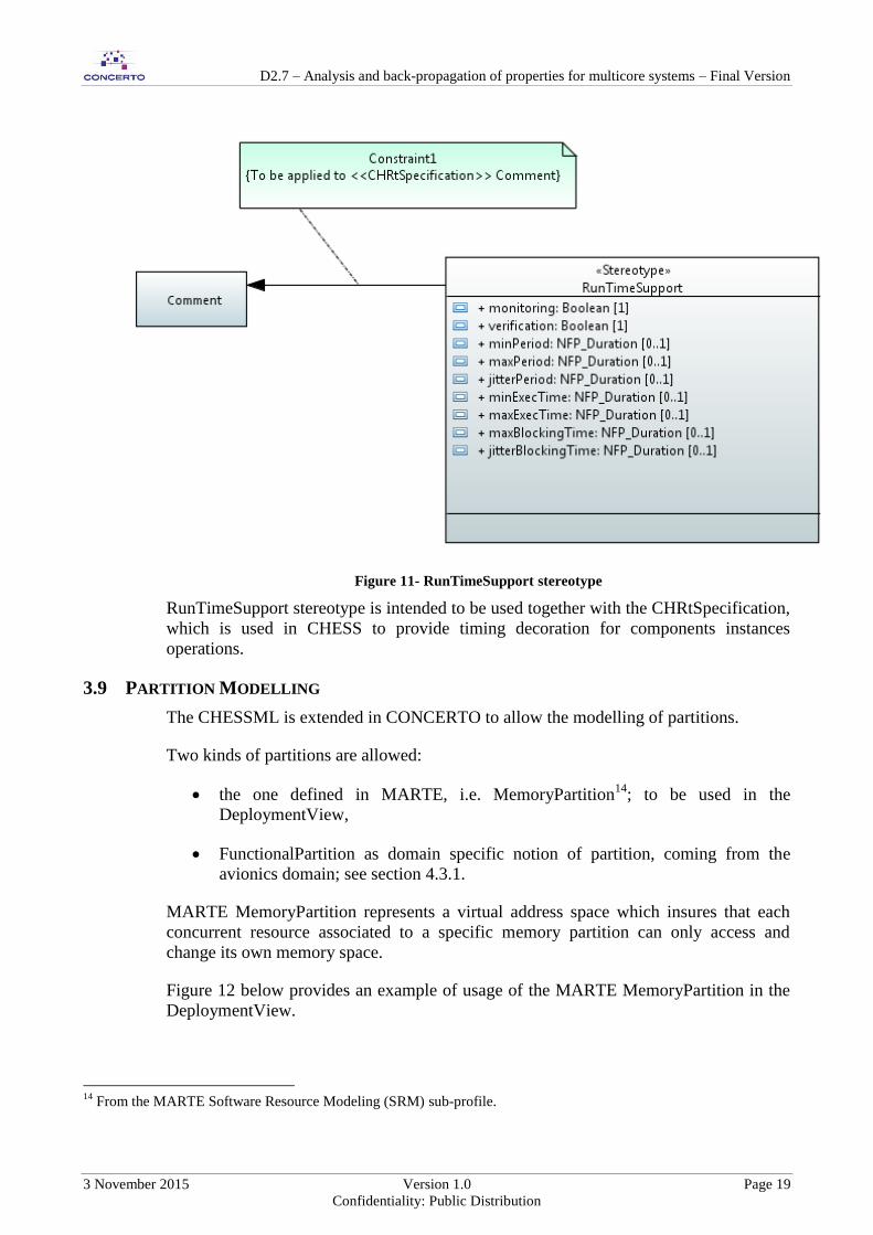
CONCERTO extends CHESSML by adding specific the RunTimeSupport, as showed
in Figure 11.
D2.7 – Analysis and back-propagation of properties for multicore systems – Final Version
3 November 2015 Version 1.0 Page 19
Confidentiality: Public Distribution
Figure 11- RunTimeSupport stereotype
RunTimeSupport stereotype is intended to be used together with the CHRtSpecification,
which is used in CHESS to provide timing decoration for components instances
operations.
3.9 PARTITION MODELLING
The CHESSML is extended in CONCERTO to allow the modelling of partitions.
Two kinds of partitions are allowed:
the one defined in MARTE, i.e. MemoryPartition14
; to be used in the
DeploymentView,
FunctionalPartition as domain specific notion of partition, coming from the
avionics domain; see section 4.3.1.
MARTE MemoryPartition represents a virtual address space which insures that each
concurrent resource associated to a specific memory partition can only access and
change its own memory space.
Figure 12 below provides an example of usage of the MARTE MemoryPartition in the
DeploymentView.
14
From the MARTE Software Resource Modeling (SRM) sub-profile.

D2.7 – Analysis and back-propagation of properties for multicore systems – Final Version
Page 20 Version 1.0 3 November 2015
Confidentiality: Public Distribution
MemoryPartition instances are bound to the given HW memory through the Allocate
MARTE relationships.
The MemoryPartition stereotype comes with the MemorySizeFootprint property which
can be used to set the size of the partition, in particular the percentage of the HW
memory which is reserved. The MemorySizeFootprint property can be specified by
creating an OpaqueExpression (e.g. named size) and then using natural language to
provide its value (see bottom part of Figure 12).
Figure 12: Using MARTE MemoryPartition
MemoryPartition instances can be decorated with criticality level (e.g. ASIL)
specification by using the CriticalitySpecification entity (see 3.4.2); this is particular
useful in case of mixed criticality system and to validate criticalities constraints, e.g. wrt
to criticalities of the software components allocated to the computing resource
connected to the HW memory and partitions.

D2.7 – Analysis and back-propagation of properties for multicore systems – Final Version
3 November 2015 Version 1.0 Page 21
Confidentiality: Public Distribution
3.10 ANALYSIS MODEL
MARTE supports the modelling of the analysis context15
, where analysis context
means:
the system, SW, HW architectural entities to be taken into account by the
analysis, with optionally their behaviour,
the extra functional information attached to them,
any other information to be given in input to the analysis, like for instance the
property to be measured.
CHESSML already adopts the MARTE analysis context for what regards
StateBasedAnalysis, FPTC and FI4FA Analysis.
CONCERTO extends CHESS by applying analysis context usage to timing analysis; in
particular MARTE analysis contexts are used to specify the platform and workload
needed for the schedulability and end-to-end analysis. The platform must comprises the
instance models of the software and hardware components while the workload is
represented by the extra functional information attached to the component instances; in
case of the end-to-end analysis, the workload must also comprise the sequence diagram
acting as the end-to-end scenario to be taken into account by the analysis (see section
3.2.2 about inter-components bindings scenarios).
3.11 ADVANCED SUPPORT FOR SPORADIC OPERATION
In CONCERTO the CHESS CHRtSpecification stereotype is extended to allow the
modelling of “composed” sporadic operations, as required by WP3, in particular by the
work concerning the integration of the synchronous approach within CHESS (see
CONCERTO deliverable D2.8 section 4.1.1 and CONCERTO deliverable D4.8 section
6.4). The goal is to be able to model that a given sporadic operation is actually activated
just after a well-defined set of operations, the latter defined in the context of the same
component, have been invoked.
The goal cited above has been reached by introducing a new property for the
CHRtSpecification named operationReqForSporadicOcc typed with a list of
Operations.
15
From the Generic Quantitative Analysis Modeling (GQAM) and Schedulability Analysis Modeling (SAM) MARTE
sub-profiles.

D2.7 – Analysis and back-propagation of properties for multicore systems – Final Version
Page 22 Version 1.0 3 November 2015
Confidentiality: Public Distribution
Figure 13: CHRtSpecification extension for sporadic operations
4 CHESSML MODIFICATION –DOMAIN SPECIFIC
This section addresses the cross-domain model-level support added to CHESSML.
4.1 PETROLEUM
The extension planned to support socio-technical systems modelling are currently
applied to the petroleum domain (see D3.2). No further extensions have been
formalized in the CHESSML for the petroleum domain.
4.2 AUTOMOTIVE
One goal of the CHESSML in CONCERTO is to support automatic verification of
ASIL decomposition in the safety ISO 26262 automotive standard meaning.
Figure 14 shows the stereotypes which have been introduced for the aforementioned
goal: Decomposition must be used to represent the set of requirements which
decompose a given parent requirements. The Independency requirement must be used to
model that the requirements which decompose a parent requirement are actually
independent, as required by the ISO 26262 standard. The rationale for the independence
can be provided by filling in the justification property of the Independency stereotype;
moreover, if it exists, a link to the Evidence e.g. a document that states why these
elements are to be considered independent, can be provided through the linkToEvidence
property.

D2.7 – Analysis and back-propagation of properties for multicore systems – Final Version
3 November 2015 Version 1.0 Page 23
Confidentiality: Public Distribution
Figure 14: CHESS stereotypes for modelling redundant ASIL decomposition
For the modelling of redundant decomposition (in the 26262 automotive standard
meaning), the CHESS toolset enforces the following modelling conventions.
In order to model ASIL decomposition (as illustrated in Figure 17) the CHESS user
must:
1. In the CHESS Requirement View: decompose the original safety requirement into
redundant requirements by creating two new SysML deriveReqt relationships
stereotyped as Decomposition, that share the same origin;
2. Assign ASILs (through CriticalitySpecification stereotype) to the decomposed safety
Requirements;
3. In the Requirement View: create an independence safety Requirement (to state that
the original safety requirement has been decomposed into two redundant ones, add
rationale to this by filling in the justification property and, if exists, a link to the
Evidence e.g. a document that states why these elements are to be considered
independent) and create the Independency relationship linking the independence
requirement to original requirement that has been redundantly decomposed;
4. In the Requirement View: create the SysML Satisfy relationships, for instance by
dragging the component\block that satisfy the decomposed safety Requirements
from the model explorer into the diagram and then creating the Satisfy relationships;
5. In the System View: Associate ASILs (through CriticalitySpecification stereotype)
to components\blocks.

D2.7 – Analysis and back-propagation of properties for multicore systems – Final Version
Page 24 Version 1.0 3 November 2015
Confidentiality: Public Distribution
Figure 15: Modelling Redundant Decomposition in CHESS
4.3 AVIONICS
4.3.1 Functional Partitions
According to the results coming from WP4 presented in CONCERTO D4.6 about
partitions support for IMA, a partition is defined in CHESSML as a UML Component
stereotyped as FunctionalPartition. The stereotype contains extra-functional properties
of the partitions (see section 3.1.3 of D4.6) about budget, scheduling ordering and
utilization.
4.3.2 ARINC Processes
Initial version of the demonstrator has revealed some limitations with respect to the
modelling of the avionics use case, i.e. the modelling of the IMA application. In order to
satisfy the requirements elaborated in the previous deliverables, new domain specific
stereotypes are introduced in the CONCERTO profile during the third year of the
project. On top of existing component features already present, they capture ARINC-
653 process definition with a single provided operation decorated with a periodic/cyclic
attribute, and a number of provided operations. These are private to the component, that
is to say not callable by other components. The periodic/cyclic operation may have an
offset. The private ones must be able to have priorities and precedence relations which
will be expressed between groups of function. This information will be used to compute
some offsets, as presented in the detailed description from below:

D2.7 – Analysis and back-propagation of properties for multicore systems – Final Version
3 November 2015 Version 1.0 Page 25
Confidentiality: Public Distribution
Figure 16: CHESS profile for ARINC processes
<<ARINCComponentImpl>>: it extends the CHESS
<<ComponentImplementation>> in order to add ARINC process semantic. It is
available in the extra functional view.
ARINCComponentImpl comes with the following constraints:
o The extended Component must be stereotyped as
CHESS::ComponentImplementation
o An <<ARINCComponentImpl >> must define one public operation
stereotyped with <<ARINC_Process>> (see below in the text)
o An <<ARINCComponentImpl >> must define a set (>=1) of
<<ARINCFunction>> operations (see below in the text)
<<ARINCProcess>>: it extends UML::Operation, UML::Comment, and is used
to map to the concept of ARINC Process, as collection of operations. It is
available in the extra functional view.
ARINCProcess comes with the following properties:

D2.7 – Analysis and back-propagation of properties for multicore systems – Final Version
Page 26 Version 1.0 3 November 2015
Confidentiality: Public Distribution
o operationsGroups: it defines how the operations which need to be
executed when the <<ARINC_Process>> operation is scheduled are
grouped; i.e. it defines which operation can run with which other. If an
operation is not mentioned in any group than it may be added to any of
them during the schedule generation. The string has to be compliant
with the given syntax:
<expr>:: "(" <operation_list> ")" [ "," "(" <operation_list> ")" ]
<operation_list> ::= <operation> [ "," <operation_list> ]
<operation> ::= <string>
e.g. ( op_1, op_4), ( op_3, op_2)
Precedencies between groups of operations can be derived from the prec-
edencies available between the operations themselves (see
<<ARINCFunction>>).
ARINCProcess comes with the following constraints:
o The owner of ARINCProcess must be an ARINCComponentImpl. The
operations listed in the operationsGroups must be ARINCFunction of the
same owning component or external operations (tagged as passive or
protected) available for the owning component through required ports.
o ARINCProcess must not have any implementation specified; the
behaviour is the “composition” of the behaviours of the operations that
can be scheduled during the ARINCProcess activation
o For ARINCComponentImpl instance, an ARINCProcess operation
should have a CHRtSpecification specifying:
The occurrence pattern occKind, i.e. information regarding the arrival
time, eventually with the phase (i.e. offset) (default is zero); Accord-
ing to MARTE specification, the arrival time can be specified as an
expression string making reference to variables, e.g.: "Period-
ic(period=(value= $MAF + 10), (unit=ms))"
The priority
The WCET is derived as the sum of the operations that can be scheduled dur-
ing the ARINCProcess activation.
ARINCFunction extends: UML::Operation, UML::Comment; it represents an
operation of the ARINCComponentImpl which maps to an ARINC function. It
is part of the ARINCProcess defined in the owning ARINCComponentImpl. It is
available in the extra functional view.
ARINCFunction comes with the following properties:
o followedBy: Operation[0..*] the operations that must run after

D2.7 – Analysis and back-propagation of properties for multicore systems – Final Version
3 November 2015 Version 1.0 Page 27
Confidentiality: Public Distribution
o rateDivider: Integer[0..1] rate divider of the period associated to the
ARINCProcess operation defined in the owning component
o offset: the phase associated will be calculated during model
transformation –from the previous relation- and directly used to set for
MAST++ the “Phase” value of the External_Event of Transaction.
ARINCFunction comes with the following constraints:
o ARINCFunction as extension of Comment must be used together with the
CHESS\MARTE CHRTSpecification stereotype to provide information
for an ARINCComponentImpl component instance.
o The owner of an ARINCFunction as extension of Operation must be an
ARINCComponentImpl.
o An ARINCFunction cannot be invoked by the public periodic operation
of the same owner component, or by other ARINCFunction operations.
o An ARINCFunction cannot appear in a provided interface of the owning
component.
o An ARINCFunction can only call protected or passive operations availa-
ble through required interfaces of the owning component.
o The operations appearing in the followedBy and precededBy lists must be
ARINCFunction of the same owning component or external operations
(tagged as passive or protected) available through required ports.
o For an ARINCComponentImpl instance, an ARINCFunction operation
should have a CHRtSpecification specifying:
the passive access mechanism, i.e. " CHRtSpecification .protection" =
"concurrent"
the WCET
the phase (i.e. offset) (default is zero)
o According to MARTE specification, phase can be specified in
the context of the periodic activation pattern, e.g.:
CHRtSpecification .occKind= "Period-
ic(phase=(value= 10), (unit=ms))"
o The value for phase is automatically derived in CHESS
o The ARINCFunction inherits the information about its periodic activation
from the ARINCProcess periodic operation of the owning component, on
which the rateDivider is applied.
The updated transformation to the analysis tool (i.e. MAST++) input model is in
charge of generating the offsets that permit a well-balanced workload over the dif-
ferent MIFs. Another role is to generate the priorities for its operations. This is a
unique integer that has to take into account both the priority inherited from the own-
ing process and the relationship of precedencies that is given by the “followedBy”
information.

D2.7 – Analysis and back-propagation of properties for multicore systems – Final Version
Page 28 Version 1.0 3 November 2015
Confidentiality: Public Distribution
4.3.3 Restriction on the deployment
In case of FunctionalPartition, the software to hardware allocation has to be compliant
with the following rules:
ARINC processes has to be allocated to Functional Partitions by using the
MARTE stereotype <<Assign>> already used in CHESSML for assigning
software components to hardware components (as showed in Annex A)
FunctionalPartitions have to be allocated to cores (by using the MARTE Assign
construct) and eventually to MemoryPartitions (if the latter are available in the
deployment view)
5 COVERAGE OF CONCERTO METAMODEL DERIVED REQUIREMENTS
This section summarizes the current coverage of the CONCERTO derived requirements
concerning the modelling language definition, i.e. the metamodel\profile.
The following tables are taken from CONCERTO D2.1 section 4 “Plan for realization”;
they summarize the requirements about the metamodel as derived by the end user
requirement elaboration made in WP4 and WP3. The column “Coverage” has been
added to trace what can be covered at M30 for what regards the modelling support, as
discussed in this document.
Table 1 - WP4, WP3 cross domain “metamodel” reqs and their coverage at M30
View WP4, WP3 refined
Requirements with
Category
“Metamodel” to be
managed through the
view
Metamodel information to be
managed through the view
Coverage at M30
SystemView
R9.1 (WP3.1) Data flow Covered
R9.2 (WP3.1) Control flow Not covered. Not
requested by the
methodology.
System-
DependabilityView
(new sub-view, see
R2.1_V1)
R2.1 (WP3.1) Availability for system elements Covered.
Dependability profile
is now applicable at
system level.
R2.3 (WP3.1) Propagation information between
system components
Covered by the new
dependability profile.
R44.1 (WP3.1)
R52.3 (WP3.1)
R2.4 (WP3.1)
Dependability attributes (with particular
focus on safety/reliability/availability),
such as failure rates, failure modes
Covered by the new
dependability profile.

D2.7 – Analysis and back-propagation of properties for multicore systems – Final Version
3 November 2015 Version 1.0 Page 29
Confidentiality: Public Distribution
View WP4, WP3 refined
Requirements with
Category
“Metamodel” to be
managed through the
view
Metamodel information to be
managed through the view
Coverage at M30
R9.3 (WP3.1) Specification of faults (for fault
propagation analysis)
Covered by the new
dependability profile.
R51.1 (WP3.1) Constructs for associating safety/risk
properties with all types of components,
including components that represent
physical equipment or
human/organizational elements
Covered by the new
dependability profile.
R39.1 (WP3.1) ASIL as system block property Covered
R61.1 (WP3.1) Argumentation of independence for the
redundant elements
Covered
R2.2 (WP3.1) Redundancy and fault-tolerance
mechanism
Partially covered by
the new dependability
profile.
Component-
FunctionalView
R1.1 (WP4.1) Modes of operation for software
components
Covered
R95.1 (WP4.4)
R9.2 (WP3.1)
Attributes to define expected flow
between inputs and outputs of
components
Covered (intra-
component bindings).
R95.2 (WP4.4) Policies that govern valid information
flows between component inputs and
outputs shall be defined.
Not covered for the
functional dimension.
Covered for what
regards failure
propagation.
R89.1 (WP4.4) Attributes to define preconditions that
must be respected before performing
certain actions.
Partially covered, see
section 3.11.
R9.1 (WP3.1) Data Flow Covered
Component-
ExtraFunctionalView
R6.2, R94.1 (WP4.1) Schedulability attributes for software
components such as period, deadline,
WCET, offset and jitter.
Covered

D2.7 – Analysis and back-propagation of properties for multicore systems – Final Version
Page 30 Version 1.0 3 November 2015
Confidentiality: Public Distribution
View WP4, WP3 refined
Requirements with
Category
“Metamodel” to be
managed through the
view
Metamodel information to be
managed through the view
Coverage at M30
R26.1 (WP4.1) Buffers, semaphores and their non-
functional properties (like, size, queuing
policy) and services to manipulate these
resources (intra and inter partition
Partially covered:
In avionic use case,
resources are
represented as
components. Size and
Queuing policy are
not taken into account.
Intra- and Inter-
partitions services can
be represented but
only intra-partitions
ones are taken into
account for timing
analysis.
O1.1 (WP4.1) Parallel tasks Not covered. Impacts
on the component
model PIM-PSM
transformation to be
studied. Support from
timing analysis tool
(MAST) already
available.
R94.2 (WP4.4) Handler associated with deadline miss Currently not covered
at model level; code
generation support for
it will be available,
with generation of
placeholder for
handler code.
R5.1 (WP4.4) Task utilization Can be derived from
existing property; in
particular it can be
derived as the ratio of
the maximum
observed
execution time over
the minimum inter-
arrival time\period.
R80.1 (WP4.4) Attributes to specify access policies, as
well as to attach these policies to
components
Covered by
CHRtSpecification
R44.1 (WP3.1)
Dependability attributes (with particular
focus on safety/reliability/availability),
such as failure rates, failure modes
Covered

D2.7 – Analysis and back-propagation of properties for multicore systems – Final Version
3 November 2015 Version 1.0 Page 31
Confidentiality: Public Distribution
View WP4, WP3 refined
Requirements with
Category
“Metamodel” to be
managed through the
view
Metamodel information to be
managed through the view
Coverage at M30
R9.3 (WP3.1) Specification of faults (for fault
propagation analysis)
Covered
R39.1 (WP3.1) ASIL, as property for software
component
Covered
R61.1 (WP3.1) Argumentation of independence for the
redundant elements
Covered
R34.1 (WP4.1) Extra-functional properties compatible
with the timing properties required by
the ASTRIUM computational model
Covered:
To our knowledge,
support of WCET and
synchronizations
trigger is compatible
and sufficient with
studidedcomputational
model
R4.1 (WP4.1) Hard or soft timing constraint. Partially covered.
Deployment-
PlatformSpecification
View
R78.1 (WP4.1) Usage of MARTE to define hardware
specific concerns
Partially Covered
R73.1 (WP4.1) Execution nodes, containing single core
or multi-core processors
Covered
R6.1 (WP4.1) Multi-core schedulers for SMP and
heterogeneous systems
Not covered by the
current support.
R6.2 (WP4.1) Schedulability attributes for hardware
components.
Multi-core schedulers for SMP and
heterogeneous systems
Partially covered:
AMP approach has
been chosen for
avionic code reuse
purpose. Multicore
scheduler is perfectly
handled including for
analysis.
R6.4 (WP4.1)
R70.1 (WP4.4)
Computational hardware resources
(processor, memory, specific resources)
for single and multi-core systems.
Combination of cache(s), memory
access and communication busses
Not covered:
Caches cannot be
modelled and their
delays cannot be
assessed.
Communication
busses like 1553
cannot not be
modelled.

D2.7 – Analysis and back-propagation of properties for multicore systems – Final Version
Page 32 Version 1.0 3 November 2015
Confidentiality: Public Distribution
View WP4, WP3 refined
Requirements with
Category
“Metamodel” to be
managed through the
view
Metamodel information to be
managed through the view
Coverage at M30
R35.1 (WP4.1) Fix priority scheduler, time-table driven
scheduler and the composition of both
of them (two-level scheduler)
Covered.
R23.1 (WP4.1) Configuration information for the
underlying platforms
Configuration
information is not
modelled in UML but
provided through
external configuration
files.
R35.2 (WP4.1) Processing nodes and cores decorated
with schedulers
Partially covered. No
support for
schedulers.
R23.2 (WP4.1) Configuration information assigned to
the nodes of the platform architecture
(Partially) Covered:
Mapping of partition
to cores and ARINC-
653 time-table
schedule are available.
R5.1 (WP4.4) CPU, system utilization attributes Partially covered
R25.1 (WP3) Hardware devices like sensors, mobile
local hubs
Not covered.
R25.2 (WP3) Network services to represent, for
example, centralized decision support
systems
Not covered.
R44.1 (WP3.1)
Dependability attributes (with particular
focus on safety/reliability/availability),
such as failure rates, failure modes
Covered
R9.3 (WP3.1) Specification of faults (for fault
propagation analysis)
Covered
R39.1 (WP3.1) ASIL, as property for hardware element Covered
R61.1 (WP3.1) Argumentation of independence for the
redundant elements
Covered
R73.1 (WP4.1) allocation of the software components
to the execution resources on execution
nodes, containing single core or multi-
core processors
Covered

D2.7 – Analysis and back-propagation of properties for multicore systems – Final Version
3 November 2015 Version 1.0 Page 33
Confidentiality: Public Distribution
View WP4, WP3 refined
Requirements with
Category
“Metamodel” to be
managed through the
view
Metamodel information to be
managed through the view
Coverage at M30
R71.1 (WP4.1) Core reservation for software
components
Covered (through
deployment view)
R46_V1 TLC specific hardware (MARTE
support with respect to the TLC relevant
properties shall be investigated)
Not covered.
Deployment-
Allocation View
R72.1(WP4.1),
R72.3 (WP4.1)
Processor affinity for (critical) software
components.
Partially covered by
the criticality
specification.
R70.2 (WP4.4) Configurations of the memories by
defining per-task memory budgets.
Not covered.
R71.3 (WP4.1) Core reservation Covered (through
deployment view)
Table 2 - WP4, WP3 domain specific “metamodel” reqs and their coverage at M18
View Domain WP4, WP3
refined
Requirements
with
Category
“Metamodel”
to be
managed
through the
view
Metamodel information to be
managed through the view
Coverage at M18
RequirementView Automotive R39.1
(WP3.1)
ASIL, as requirement property. Covered
SystemView
Petroleum R53.1 Barriers, Dynamic properties of
barriers
Covered by the
socio-technical
system profile
SystemView-
ExtraFunctionalView
Petroleum R50.1 Risk Covered by the
dependability
profile.
SystemView-
ExtraFunctionalView
Petroleum R50.2 Computational model/formula at
design time for aggregation of safety
properties
Covered by
dependability
analysis.
Component-
ExtraFunctional
View
Automotive R43.1 Specification of application level
failure code and diagnostic services
provided by the run time environment
Not covered.

D2.7 – Analysis and back-propagation of properties for multicore systems – Final Version
Page 34 Version 1.0 3 November 2015
Confidentiality: Public Distribution
View Domain WP4, WP3
refined
Requirements
with
Category
“Metamodel”
to be
managed
through the
view
Metamodel information to be
managed through the view
Coverage at M18
Deployment-
PlatformSpecification
View
Telecare R23.1
(WP3.1)
Telecare domain specific
configuration information
Not covered at
UML model level;
to be provided
through external
configuration files.
Deployment-
PlatformSpecification
View
Telecare R23.2
(WP3.1)
Configuration information assigned to
the nodes of the platform architecture
Not covered at
UML model level;
to be provided
through external
configuration files
Deployment-
PlatformSpecification
View
Telecom R18.1(WP3.1) Mobile device domain-specific
configuration
Not covered at
UML model level;
to be provided
through external
configuration files
Deployment-
PlatformSpecification
View
Automotive R40.1
(WP3.1)
Assignment of can data bases (DBC)
to a CAN networks
Not covered
Deployment-
PlatformSpecification
View
Automotive R85.1
(WP3.1)
CAN, LIN, FlexRay busses/protocols Not covered
Deployment-
Allocation View
Telecare R25.4
(WP3.1)
Dynamic reconfiguration of
allocations
Not covered.
6 CONCLUSION
The document reports the extensions which have been made to the original CHESS
modelling language to satisfy the CONCERTO requirements. Several modifications
have been identified by improving some limitations of the CHESSML. Additionally,
new extensions needed for CONCERTO have been proposed like the new dependability
profile, the modelling concepts of criticality levels, partitions and operational modes.
Moreover a domain specific set of extensions have been identified for the Automotive
and Avionics domains.

D2.7 – Analysis and back-propagation of properties for multicore systems – Final Version
3 November 2015 Version 1.0 Page 35
Confidentiality: Public Distribution
7 REFERENCES
[AV] A. Avizienis, J.C. Laprie, B. Randell, C. Landwehr. Basic concepts and taxonomy
of dependable and secure computing. In: IEEE Trans. Dependable Sec. Comput.1(1):
11-33, 2004.
[CHESSD232] D2.3.2 – Multi-concern Component Methodology (MCM) and Toolset
Version 1.0, 10 January 2012, CHESS Artemis Project Number 216682 (available at
http://www.chess-project.org/page/results)
A. An introduction to the CHESSML profile
This section provides an introduction to the main parts of the CHESSML, relevant for
CONCERTO, as resulting from the CHESS project (no CONCERTO extensions), by
illustrating some modelling examples. A basic knowledge of the UML standard is
required.
Figure 17: CHESS model and views predefined structure
Following figures shows the definition of Interfaces and ComponentTypes.
Figure 18: Interfaces
Figure 19: ComponentTypes

D2.7 – Analysis and back-propagation of properties for multicore systems – Final Version
Page 36 Version 1.0 3 November 2015
Confidentiality: Public Distribution
Figure 20 shows the definition or provided and required ports for a given Compo-
nentType.
Figure 20: ComponentType’s provided and required ports
Figure 21 shows the ComponentImplementations, where each
ComponentImplementation realizes a given ComponentType. The
ComponentImplementation inherits all the specification from the realized
ComponentType, in particular ports with provided\required interfaces and operations;
then ComponentImplementations can be used to provide implementation details, and
then they can be instantiated and connected together.
Figure 21: CHESS ComponentImplementation
Figure 22 shows an example of intra-component binding (as of activity diagram) for the
Produce operation implemented by the Producer_impl ComponentImplementation ap-
pearing in Figure 21; in particular it is modelled that the implementation of the Produce
operation perform a call of Store and then Consume operations through required ports of
Producer_impl (the On port field visible in the property editor in Figure 22 allows to
specify the required port through which the operation call currently selected applies).

D2.7 – Analysis and back-propagation of properties for multicore systems – Final Version
3 November 2015 Version 1.0 Page 37
Confidentiality: Public Distribution
Figure 22: Intra-component binding
Figure 23 shows an example of ComponentImplementations instantiation and connec-
tion. The instances (in yellow in the figure) are represented as internal part of a root
component, the latter representing the entire SW system under design. Each instance
comes with the provided and required ports defined for the typing ComponentImple-
mentation.
Figure 23: CHESS ComponentImplementation instances
Figure 24 shows an example of timing annotation for ComponentImplementation in-
stances, by using MARTE RtSpecification stereotype decorating operations exposed
through provided ports:

D2.7 – Analysis and back-propagation of properties for multicore systems – Final Version
Page 38 Version 1.0 3 November 2015
Confidentiality: Public Distribution
Figure 24: CHESS timing annotation
Figure 25 shows an example of instance model (tree-like view) derived from the model
represented in Figure 24; in particular the instances of the software component are rep-
resented under the SwSystem_instSpec package.
Figure 25: CHESS Instance Model
Figure 26 shows an example of deployment, so about the platform specification; in this
case only one computational resource is defined (in grey in the figure). Moreover the
software to hardware component instances allocations are modelled using MARTE As-
sign constructs. Each Assign comes with from and to attributes through which the soft-
ware instance (from) which is allocated to the hardware instance (to) can be specified.

D2.7 – Analysis and back-propagation of properties for multicore systems – Final Version
3 November 2015 Version 1.0 Page 39
Confidentiality: Public Distribution
Figure 26: CHESS deployment model
Figure 27 shows hardware entities and ComponentImplementations enriched with de-
pendability information (about stateful, stateless) useful for state-based analysis (SBA).
Figure 27: Dependability information annotated HW components
Figure 28 shows the State-Based analysis context used to run the state-based analysis.
Figure 28: SBA analysis context
Figure 29 shows how the information about FPTC rules (on the top of the figure) and
failure types occurring on top level-input ports (on the left of the bottom figure) can be

D2.7 – Analysis and back-propagation of properties for multicore systems – Final Version
Page 40 Version 1.0 3 November 2015
Confidentiality: Public Distribution
provided for ComponentImplementations at type and instance level, to allow FPTC
analysis.
Figure 29: FPTC specification
Figure 30 shows how the results of the FPTC analysis about failure types occurring at
output-port level are back propagated in the model.
Figure 30: Results of the FPTC analysis
B. CONCERTO Dependability Profile
This section describes the new CHESS modelling language for dependability. The
profile is based upon the conceptual dependability model presented in CONCERTO
D3.2; the profile is defined here by taken into account the top-level requirements
coming from WP3, which concern the possibility to apply dependability information at

D2.7 – Analysis and back-propagation of properties for multicore systems – Final Version
3 November 2015 Version 1.0 Page 41
Confidentiality: Public Distribution
type and instance level and the possibility to use the dependability profile at System,
Component and Deployment level (in particular for the latter for what regards HW
platform entities).
The proposal here is intended as replacement of the previous CHESSML Dependability
Profile [CHESSD232]. The diagram of the dependability conceptual model is shown in
Figure 31, as appearing in D3.2, then some further UML profile detail are provided in
the following text.
Figure 31: Proposal for the CONCERTO dependability conceptual model.
B.1 STEREOTYPES
Here we list the stereotypes that are foreseen in the implementation of the CONCERTO
dependability profile.
«FailureMode»
o Extends
UML::Class

D2.7 – Analysis and back-propagation of properties for multicore systems – Final Version
Page 42 Version 1.0 3 November 2015
Confidentiality: Public Distribution
o Description
This element represents a failure mode of a component. Failure
modes should be associated to components‟ ports.
o Attributes
name : String [1]
description : String [0..1]
exposure : String [0..1]
controllability : String [0..1]
likelihood : String [0..1]
«FLABehavior»
o Extends
UML::Component, SysML::Block, UML::Connector,
UML::InstanceSpecification
o Description
This stereotype should be similar to the one used in CHESS, where

D2.7 – Analysis and back-propagation of properties for multicore systems – Final Version
3 November 2015 Version 1.0 Page 43
Confidentiality: Public Distribution
the failure behavior is described using a FPTC / FI4FA specification.
If a <<FlaSpecification>> Connector or InstanceSpecification (as
instance of Connector) does not have dependability-related
stereotypes, then it is assumed that failures are propagated “as they
are”, e.g., one “omission” on one end is propagated as an “omission”
on the other end. Otherwise dependability annotations can be used to
i) specify a mapping between failure modes on one side, and failure
modes on the other side; or ii) specify failure behavior of the
connector itself (e.g., a network cable may break). In this case, we
should consider (if possible) the failure modes associated to the two
ports between which the connector (instance) is placed (through the
ConnectorEnd elements in case of the Connector or by using the
owned Slots, i.e. the instances of the connected ports, in case of the
InstanceSpecification)
o Attributes
fptc : String [1]
«SimpleStochasticBehavior»
o Extends
UML::Class, UML::Property, UML::Connector,
UML::InstanceSpecification
o Description
This stereotype is meant to replace the Stateless/Stateful
Software/Hardware stereotypes (those were considered difficult to
handle/understand by industrial users in CHESS).
o Attributes
failureOccurrence : MARTE_Library::NFP_Real [1]

D2.7 – Analysis and back-propagation of properties for multicore systems – Final Version
Page 44 Version 1.0 3 November 2015
Confidentiality: Public Distribution
repairDelay : MARTE_Library::NFP_Real [0..1]
failureModesDistribution : String [0..1]
«ErrorModelBehavior» (replace «DependableComponent»)
o Extends
UML::Class, UML::Property, UML::Connector,
UML::InstanceSpecification
o Description
This stereotype is used to attach an error model to a system element
(component/block/connector)
o Attributes
errorModel : CHESSML::ErrorModel [1]

D2.7 – Analysis and back-propagation of properties for multicore systems – Final Version
3 November 2015 Version 1.0 Page 45
Confidentiality: Public Distribution
«ErrorModel»
o Extends
UML::StateMachine
o Description
An error model state machine (as in CHESSML)
«InternalFault»
o Extends
UML::Transition
o Description
An internal fault transition, i.e., a state transition caused by an internal
fault.
An internal fault can bring the component to a state different from the
initial state, but can also make the component move between two
internal states.
o Attributes
occurrence : MARTE_Library::NFP_Real [0..1]
weight : Double [0..1]

D2.7 – Analysis and back-propagation of properties for multicore systems – Final Version
Page 46 Version 1.0 3 November 2015
Confidentiality: Public Distribution
«InternalPropagation»
o Extends
UML::Transition
o Attributes
externalFaults : String [1]
Specification of which external faults (i.e., failures of
connected components trigger this internal propagation
transition). This attribute should be a string complying with
the following grammar:
modeexp ::= Port „.‟ mode | modeexp „AND‟ modeexp |
modeexp „OR‟ modeexp | „NOT‟ modeexp
mode ::= FailureMode | „nofailure‟
As examples, two valid strings are:
“p1.omission”
“(p1.commision AND p2.nofailure) OR p3.late”
o Description
An error propagation occurring within the component. The
propagation is caused by the occurrence of external faults.
o Attributes
delay : MARTE_Library::NFP_Real [0..1]
weight : Double [0..1]
«Failure»
o Extends
UML::Transition
o Attributes
modes : String [1..*]
Specification of which failure modes affect which ports of the
component. This attribute should be an array of strings
complying with the following grammar:
modes ::= Port „.‟ mode | Port „.(‟ modeprob „)‟
mode ::= FailureMode | „nofailure‟
modeprob ::= prob “ : ” FailureMode | modeprob „, ‟ modeprob
prob ::= Double
As examples, two valid strings are:
“p1.omission”
“p2.(0.2 : omission, 0.8 : commission)”
delay : MARTE_Library::NFP_Real [0..1]
o Description
The occurrence of a failure of the component (i.e., an erroneous
component state reaches the service interface). The modes attribute is

D2.7 – Analysis and back-propagation of properties for multicore systems – Final Version
3 November 2015 Version 1.0 Page 47
Confidentiality: Public Distribution
used to specify which failure modes affect the different ports of the
component.
Having failures as events/transitions is in line with the “classical”
definition given by the taxonomy of Avizienis et al [AV]. There
could be for example situations where a component, as a
consequence of a failure moves back to the initial state. For example,
a component may produce a wrong output as a consequence of a
particular input, but then produce correct output in the following.
«NormalState»
o Extends
UML::State
o Description
A state of the component that is considered “normal”, i.e., in which
the component is providing its full functionalities.
«ErrorState»
o Extends
UML::State
o Description
A state of the component that is considered erroneous (i.e., not
complying with the specifications).
«DegradedState»
o Extends

D2.7 – Analysis and back-propagation of properties for multicore systems – Final Version
Page 48 Version 1.0 3 November 2015
Confidentiality: Public Distribution
UML::State
o Description
A state of the component in which it is not delivering its complete
functionalities, but which was foreseen in the specifications (e.g.,
reduced services due to maintenance activities).
«ErrorDetection»
o Extends
UML::Transition
o Attributes
delay : MARTE_Library::NFP_Real [0..1]
successProbability : Double [0..1]
o Description
An error detection transition. Can be used in components‟ error
models.
o Constraint
from “ErrorState” to any State
«ErrorHandling»
o Extends
UML::Transition
o Attributes
delay : MARTE_Library::NFP_Real [0..1]
successProbability : Double [0..1]
o Description
An error handling transition. Can be used in components‟ error
models.
o Constraint
from “ErrorState” to any State
« FaultHandling »
o Extends
UML::Transition
o Attributes
delay : MARTE_Library::NFP_Real [0..1]

D2.7 – Analysis and back-propagation of properties for multicore systems – Final Version
3 November 2015 Version 1.0 Page 49
Confidentiality: Public Distribution
successProbability : Double [0..1]
o Description
A fault handling transition. Can be used in components‟ error models.
o Constraint
From any State (except the InitialState) to any State
«Propagation»
o Extends
UML::Connector, UML::InstanceSpecification
o Attributes
delay : MARTE_Library::NFP_Real [0..1]
probability : Double [0..1]

D2.7 – Analysis and back-propagation of properties for multicore systems – Final Version
Page 50 Version 1.0 3 November 2015
Confidentiality: Public Distribution
«M&MActivity»
o Extends
UML::Activity
o Attributes
when : String [1]
Specification of when the activity should be triggered. This
attribute should be a strings complying with the following
grammar:
S ::= T „[‟ EX „]‟ | T „[‟ EX „] {‟ L „}‟
T ::= „Immediately‟ | „AtTime(‟ R „)‟ | „Periodic(‟ D „)‟
EX ::= „(‟ EX „and‟ EX „)‟ | „(‟ EX „or‟ EX „)‟ | „not‟ EX | „true‟ | FD
FD ::= „Failed(‟ FailureMode „)‟ | „Failed(‟ Port „.‟ FailureMode „)‟ |
„Detected(‟ ErrorState „)‟
L := „Before(‟ R „)‟ | „After(‟ R „)‟ | „Interval(‟ R „,‟ R „)‟
R ::= MARTE::NFP_Real
As examples, two valid strings are:
“Immediately [ p1.omission ]”
“Periodic( 720 ) [ true ] { After(8760) }”
o Description
An activity related to maintenance, which may be composed of
multiple actions (M&MAction). The “when” attribute specifies the
conditions that should hold for this activity to be triggered.
«M&MAction» (abstract)
o Extends
UML::Action
o Attributes
duration : MARTE_Library::NFP_Real [0..1]
probSuccess : Double [1]
targets : UML::Property [*]

D2.7 – Analysis and back-propagation of properties for multicore systems – Final Version
3 November 2015 Version 1.0 Page 51
Confidentiality: Public Distribution
o Description
An action belonging to an M&MActivity.
«M&MAction»
o Extends
UML::Action
o Attributes
duration : MARTE_Library::NFP_Real [0..1]
probSuccess : Double [1]
o Description
An action belonging to a M&MActivity.
«Repair»
o Extends
CHESSML::M&MAction
o Attributes
targets : UML::Property [*]
o Description
A repair action performed on a component (or set of components).
Repair brings the component back to its initial healthy state.
«Detection»
o Extends
CHESSML::M&MAction
o Attributes
target : UML::Property [1]
detectableStates : CHESSML::ErrorState [1..*]
onDetection : CHESSML::M&MAction [*]
o Description
An error detection activity performed on a component to detect
specific erroneous states defined in its error model.
«Recovery»
o Extends
CHESSML::M&MAction
o Attributes
target : UML::Property [1]
recoveryState : UML::State [1]
o Description
A recovery activity that brings a component in a specific state.
«StateBasedAnalysis»
o Extends
MARTE::GQAM::GaAnalysisContext
o Attributes
measure : String [1]
measureEvaluationResult : String [0..1]
targetInstances : UML::InstanceSpecification [*]

D2.7 – Analysis and back-propagation of properties for multicore systems – Final Version
Page 52 Version 1.0 3 November 2015
Confidentiality: Public Distribution
targetPort : UML::Slot (as instance of Port) [*]
targetFailureModes : CHESSML::FailureMode [*]
initialConditions : CHESSML::SBAInitialConditions [*]
o Description
Definition of measures of interest for state-based analysis as in
CHESS. The target may be specified by specifying i) only the
component instances, ii) specific ports of those instances, or iii)
specific failure modes of those ports.
StateBasedAnalysis can have one or more initial conditions to be
applied to the analysis.
«SBAInitialConditions»
o Extends
UML::Component
o Attributes
targetInstance : UML::InstanceSpecification [1]
setup : String [1]
Specification of the probability distribution of initial states of
the component. This attribute should be a strings complying
with the following grammar:
SETUP ::= „{‟ SP „}‟
SP ::= SP „,‟ SP | S „:‟ P
S ::= UML::State | „Healthy‟ | F
F ::= „Failed(‟ FailureMode „)‟ | „Failed(‟ Port „.‟ FailureMode „)‟
P ::= MARTE::NFP_Real
As examples, two valid strings are:
“{ Failed(p1.omission) : 1.0 }”
“{ Healthy : 0.8, Erroneous : 0.2 }”
o Description
This stereotype is used to specify initial conditions for components of
the system (e.g., healthy, failed, etc.).

D2.7 – Analysis and back-propagation of properties for multicore systems – Final Version
3 November 2015 Version 1.0 Page 53
Confidentiality: Public Distribution
Other comments
o «FLABehavior» and «SimpleStochasticBehavior» could in principle coexist
on the same component.
B.2 NOTES ABOUT THE CURRENT IMPLEMENTATION
All the stereotypes defined in the previous version of the CHESS dependability profile
are kept in the current implementation to be able to still use the current transformations
and analysis; they appear in this document as deprecated (see below).
B.2.1 Deprecated stereotypes
The following entities (stereotypes and\or properties) from the old CHESS
dependability profile are deprecated:
(deprecated NEW(optional))
FPTCSpecification.failure FPTCSpecification.failureMode
FPTC FLABehavior
FPTCPortSlotFailureModes
FailureTypeFailureMode
DependableComponent ErrorModel
ErrorState.type
ErrorState.vanishingTime
B.2.2 Renamed Stereotypes
ErrorErrorState
Propagation.propDelay=Propagation.delay

D2.7 – Analysis and back-propagation of properties for multicore systems – Final Version
Page 54 Version 1.0 3 November 2015
Confidentiality: Public Distribution
B.2.3 About the FPTCSpecification
FPTCSpecification, as defined in the old profile, allows storing failures for ports by
using composite structure diagrams, i.e. by using annotated Comments attached to port-
part pairs. I.e. the modeller can use the FPTCSpecifications in the composite diagram to
provide the faults in input (as fault injection); at the same time the tool uses
FPTCSpecifications to back propagate the propagated failures, as resulting from the
analysis.
FPTCSpecification is kept in the current version of the profile to allow an initial smooth
customization of the implementations currently available for the FPTC analysis; for this
goal a dedicated relationship between FailureModes and FPTCSpecification has been
added in place of the one between FPTCPortSlot and FPTCSpecification defined in the
old profile. So, to reuse the current FPTC implementation, FailureModes should be used
in place of the FPTCPortSlot; then FailureModes at Slot level can be linked to the
<<FPTCSpecification>> Comments modelled in the composite diagram.
However the final goal (in CONCERTO or after) should be to avoid the use of the
FPTCSpecification in place of the usage of the FailureModes stereotype. In other words
the user should be able to use the InstanceView to attach failures to ports, in particular
by using FailureModes attached to Slots, the latter as instances of ports, without the
need to create the FPTCSpecification. So the usage of stereotyped comments, needed to
work with the composite diagram for ports decoration, would not be useful anymore.
It is worth noting that the current FPTC analysis already considers the instance level, so
it already considers the InstanceSpecifications and Slots entities, retrieving the
FPTCSpecification starting from them; the resulting failures are currently back
propagated to the FPTCSpecifications just to allow the modeller to see the results by
using the composite diagram. So what we should implement is a new view to allow the
modeller to check the results directly by looking at the InstanceView, without the need
to switch to the composite diagram. The usage of composite diagram also has some
limitation in case of hierarchical systems, with a hierarchy level > 2, and the new view
for FPTC result built on top of the InstanceView would solve these limitations.

D2.7 – Analysis and back-propagation of properties for multicore systems – Final Version
3 November 2015 Version 1.0 Page 55
Confidentiality: Public Distribution
C. About MARTE usage in the CHESSML
This section summarizes the set of MARTE entities which are used in CHESSML and
in the views defined by CHESS.
Component model (CHESS SystemView, ComponentView,
PlatformSpecificationView)
Operational modes can be defined for the given system under design by using MARTE
stereotypes (defined in the CoreElements sub-profile), and in particular the stereotyped
ModeBehavior state machine, together with Mode states and ModeTransition
transitions. ModeTransition can be added in the state machine in response to an event to
model how a given change of mode is activated in the system.
The ModeBehavior state machine can be defined at system, component or hardware
level.

D2.7 – Analysis and back-propagation of properties for multicore systems – Final Version
Page 56 Version 1.0 3 November 2015
Confidentiality: Public Distribution
Component model (CHESS ComponentView)
MARTE GCM16
::ClientServerPort and FlowPort entities are used in CHESSML to
model services and data ports respectively for software components (i.e.
CHESSML::ComponentImplementation and CHESSML::ComponentType).
The MARTE HLAM17
::RtSpecification is used in CHESSML to model the following
properties for a given operation owned by a software component (i.e.
CHESSML::ComponentImplementation):
Arrival pattern (i.e., periodic, sporadic) (occKind attribute)
Relative deadline (relDl attribute)
Priority (priority attribute).
In addition, HLAM::RtSpecification is extended in CHESSML (as CHRtSpecification
stereotype, see Figure 32) to also allow the specification of the following properties for
components operations:
worst case execution time (WCET),
protected\unprotected access (protection stereotype‟s field),
ceiling priorities (for protected operations only).
the set of operations that need to be invoked to allow the operation invocation
(invokedoperationReqForSporadicOcc stereotype‟s field); for sporadic
operations only.
Regarding the aforementioned timing properties, any property value (e.g., the period
duration) can be expressed in MARTE by using a complex type which, in addition to
the value, has a “mode” attribute which allows specifying the operational mode(s) (as
MARTE::CoreElements::Mode) in which the provided values are valid.
The partWithPort relationship available for CHRtSpecification allows to model timing
annotation for operations which are provided by a given Property, the latter as instance
of component owned by a composite component. The Property and the associated
CHRtSpecification can be modelled\visualzed through the UML composite structure
diagrams.
The MARTE HLAM::RtFeature is extended in CHESSML (as CHRtPortSlot
stereotype, see Figure 32) to allow application of CHRtSpecification to a given instance
of component‟s port (Slot in UML).
16
the MARTE Generic Component Model (GCM) sub-profile. The “::” denotes the namespace where the stereotype is
defined. 17
the MARTE High-Level Application Modeling (HLAM) sub-profile

D2.7 – Analysis and back-propagation of properties for multicore systems – Final Version
3 November 2015 Version 1.0 Page 57
Confidentiality: Public Distribution
Figure 32: MARTE HLAM::RtSpecification and HLAM::RTFeature CHESSML extensions
Platform specification (CHESS PlatformView)
The modelling of the platform is allowed in CHESSML by using the stereotypes available in
the MARTE Hardware Resource Modeling (HRM) sub-profile. In particular processors can
be modelled in CHESS by using the MARTE HRM::HwProcessor entity, while busses
connecting processors can be modelled by using the MARTE HRM::HWBus entities.
MARTE HRM::HwProcessor comes with the nbCores attribute (as natural numerical value)
which allows to specify the number of cores within the HwProcessor.
MARTE SRM18
::MemoryPartition is used in CHESSML to represents a virtual address space
which insures that each concurrent resource associated to a specific memory partition can
only access and change its own memory space.
Software to hardware allocation (CHESS AllocationView)
MARTE Alloc19
::Assign is used in CHESSML to model software to hardware component
(i.e. HRM::HWProcessor) instances allocation.
18
MARTE Software Resource Modeling (SRM) sub-profile

D2.7 – Analysis and back-propagation of properties for multicore systems – Final Version
Page 58 Version 1.0 3 November 2015
Confidentiality: Public Distribution
MARTE Alloc::Assign can be constrained by the MARTE NFPs20
::NFPConstraint construct,
where the latter allows specifying the operational mode(s) (as
MARTE::CoreElements::Mode) for which the Assign holds.
Alloc::Assign can be constrained with NFPs::NFPConstraint where the latter is used to
specify the core of the target processor (HRM::HWProcessor) on which the allocation is
performed; the target core is provided as numerical value in the NFPs::NFPConstraint
specification, according to the number of cores within the HRM::HwProcessor (nbCores
attribute) .
Analysis context (CHESS AnalysisView)
CHESSML uses the MARTE SAM21
::SaAnalysisContext entity to specify the information
needed to perform a given analysis.
MARTE GQAM22
::GaResourcePlatform is used in CHESSML as logical container for the
resources referred by an analysis context. CHESSML extends the GQAM
::GaResourcePlatform (as CHGaResourcePlatform stereotype) in order to be applied to UML
Packages (MARTE GaResourcePlatform extends the UML Classifier only). In fact in CHESS
the resources referred by an analysis context are component instances which are available in a
dedicated UML package.
MARTE GQAM::GaWorkloadBeahavior and SAM::SaEndtoEndFlow are used in
CHESSML (in the AnalysisView) to refer a sequence diagram modelled in the
ComponentView (in detail, GaWorkloadBeahavior and SaEndtoEndFlow are applied to a
UML activity which has a CallBehaviorAction pointing to the UML Interaction representing
the information modelled in the sequence diagram). GaWorkloadBehavior can then be used
to attach the referred sequence diagram to an analysis context, the latter used to feed end-to-
end response time analysis; SaEndtoEndFlow is used to provide an end-to-end deadline for
the behaviour modelled in the sequence diagram.
PSM (PSMView)
MARTE SAM::SaExecHost is used in CHESSML to represent at PSM level (in the
PSMView) the HRM::HwProcessor modelled in the PlatformView. SAM::SaExecHost allows
to specify the running schedulable resources, the latter generated in the PSM by the PIM to
PSM CHESS transformation.
MARTE SRM23
::SwSchedulableResource is used in CHESSML to represent PSM resources
that execute concurrently to other concurrent resource. SRM::SwSchedulableResource comes
with a priority field associated.
MARTE SRM::SwMutualExclusionResource and SAM::SaSharedResource are used in
CHESSML to model protected resources in the PSMView. 19
MARTE Allocation Modeling sub-profile 20
MARTE Non-functional Properties Modeling (NFPs) sub-profile 21
Schedulability Analysis Modeling (SAM) sub-profile 22
Generic Quantitative Analysis Modeling (GQAM) sub-profile 23
Software Resource Modeling (SRM) sub-profile

D2.7 – Analysis and back-propagation of properties for multicore systems – Final Version
3 November 2015 Version 1.0 Page 59
Confidentiality: Public Distribution
SRM::SwMutualExclusionResource allows to specify the type of protection protocol used to
access the resource (e.g. priority ceiling).
MARTE SAM::SaStep is used in CHESSML to represent an operation in the PSM having the
following properties:
Execution time (execTime:NFP_Duration) as specified in the component view
Blocking time (blockT:NFP_Duration) (retrieved by the analysis)
Response time (respT):NFP_Duration (retrieved by the analysis)
The list of called operations (subUsage:ResourceUsage [0..*]), as specified in the
component model intra-component bindings; this information allows to calculate the
blocking time.
The shared resource where the operation‟s behaviour is executed
(sharedResource:SaSharedResource [0..1])
The resource which executes the behaviour (concurRes:SchedulableResource [0..1])
The SAM::SaAnalysisContext modelled in the AnalysisView is mapped to a corresponding
SAM::SaAnalysisContex entity in the PSM. The SAM::SaAnalysisContext in the PSM
refers the entities of the PSM which are relevant for the analysis, in particular the
SAM::SaStep, SRM::SwSchedulableResource and SRM::SwMutualExclusionResource+
SAM::SaSharedResource protected resources.


