

FIONA Deliverable D2.3.1
FIONA Platform Architecture
Final Version of Deliverable
• • • • • • • • • • • • • • • • • • • • • • • • • • • • • • • • • • • • • • • • • • • • •
Document status: Final version
Dissemination level: Public
Version: 2.0
Submission date: June 25th 2015
Authors: Dennis Stampfer, Christian Schlegel (Hochschule Ulm)
Contributors: Mathias Bürger, Christopher Brown, Wei Mao (Bosch)
Mitja Pugelj (Comland)
Neda Petreska, Ali Golestani (Fraunhofer ESK)
Stefan Rueping (Infineon)
Çağlar Akman (Havelsan)
Supported by
Germany – Federal Ministry of Education
and Research (BMBF)
Slovenia – Ministry of Economic
Development and Technology (MGRT)
Czech Republic – Ministry of Education,
Youth and Sports (MSMT)

Deliverable D2.3.1 FIONA Platform Architecture
FIONA ITEA 2 – 12038
Page 2 of 44
Document History
Version / Date Author Remarks
v0.1, June 6 2014 Dennis Stampfer Initial document draft for review by partners.
v1.0, June 23 2014 Dennis Stampfer Initial version of deliverable.
V1.1, May 21 2015 Dennis Stampfer Final version draft for review by partners.
v2.0, June 25 2015 Dennis Stampfer Final version of deliverable.

Deliverable D2.3.1 FIONA Platform Architecture
FIONA ITEA 2 – 12038
Page 3 of 44
Table of Contents
1. Introduction................................................................................................................................... 4
2. Architectural Principles and Workflow ........................................................................................ 5
2.1. Architectural Elements ........................................................................................................... 5
2.1.1. Components ............................................................................................................... 5
2.1.2. Services ...................................................................................................................... 5
2.1.3. Communication Pattern ............................................................................................... 6
2.1.4. Communication Object ................................................................................................ 6
2.2. Workflow ................................................................................................................................ 7
2.2.1. SmartSoft ................................................................................................................... 8
2.2.2. Service Definition ........................................................................................................ 9
2.2.3. Component Level ........................................................................................................ 9
2.2.4. Concrete Application ................................................................................................. 10
2.3. Further Reading and Resources........................................................................................... 11
3. FIONA Platform Architecture ...................................................................................................... 12
3.1. Software Architecture ........................................................................................................... 12
3.1.1. Sensors .................................................................................................................... 12
3.1.2. Environment Perception ............................................................................................ 17
3.1.3. Localization .............................................................................................................. 18
3.1.4. Navigation ................................................................................................................ 20
3.1.5. Security .................................................................................................................... 24
3.1.6. Human Machine Interaction ...................................................................................... 25
3.2. Hardware Architecture ......................................................................................................... 28
3.3. Equipping the SmartMDSD Toolchain with FIONA Architectural Elements ............................ 29
3.3.1. Modeling FIONA Building Blocks ............................................................................... 30
3.3.2. Composing the HSU iBeacon Demonstrator .............................................................. 32
3.3.3. Possible variations .................................................................................................... 34
4. FIONA Demonstrator 1 Architecture: "Smartphone Navigator" ................................................ 37
4.1. Software Architecture ........................................................................................................... 37
4.2. Hardware Architecture ......................................................................................................... 39
5. FIONA Demonstrator 2 Architecture: "Navigation Assistant" .................................................. 40
5.1. Software Architecture ........................................................................................................... 40
5.2. Hardware Architecture ......................................................................................................... 42
6. Index of Service Descriptions .................................................................................................... 43
7. Bibliography ................................................................................................................................ 44

Deliverable D2.3.1 FIONA Platform Architecture
FIONA ITEA 2 – 12038
Page 4 of 44
1. Introduction
FIONA aims to develop a modular, accessible framework to support the core functions of localisation
and navigation in indoor and outdoor areas as well as to facilitate the development of applications and
services to be built upon it. The FIONA software architecture follows the principles of a service -
oriented and component-based design. It provides the structure for implementing a variety of software
components within the application domain of FIONA and supports the composition of these building
blocks to applications. Applications can be composed out of any combination of in -house components
and components of 3rd-party suppliers offered within an app-store-like market place.
The document describes two different aspects:
It describes the architectural principles and the according workflow used to structure the
FIONA domain. These are both considered stable and ground the design of systems on stable
entities (services). They ensure system level conformance, define responsibilities and facilitate
the identification of white spots (required services that no-one provides or provided services
that no-one requires) that have to be covered in a very early stage of the workflow. The
strength of this structured workflow is that architectural patterns and FIONA specific structures
can be identified very early and in parallel to implementations of FIONA functionalities.
It describes how the FIONA Project did apply these architectural principles and used the
workflow in order to define concrete FIONA services and to define the granularity of FIONA
software components. The services went through several iterations and finally converged
towards the appropriate set of FIONA software services and granularities of FIONA software
components. The service-oriented component model naturally supports competing alternatives
as building blocks for systems while still ensuring composability. Thus, openness with respect
to software service definitions is in no way in conflict with the progress in implementations.
Deliverable D2.3.1 FIONA Platform Architecture
FIONA ITEA 2 – 12038
Page 5 of 44
2. Architectural Principles and Workflow
This chapter describes the architectural principles and the according workflow used to structure the
FIONA domain.
2.1. Architectural Elements
The FIONA platform is based on the service-oriented component-based approach SmartSoft [1] [2] [3]
[4]. A component provides a hull for implementing functionality. Even though functionality is important
for a system to "do" anything, the most important building blocks for the architecture are services.
Services can be provided ("made available") or required ("used") by components and are used for
component interaction. Services are composed out of communication patterns and communication
objects.
2.1.1. Components
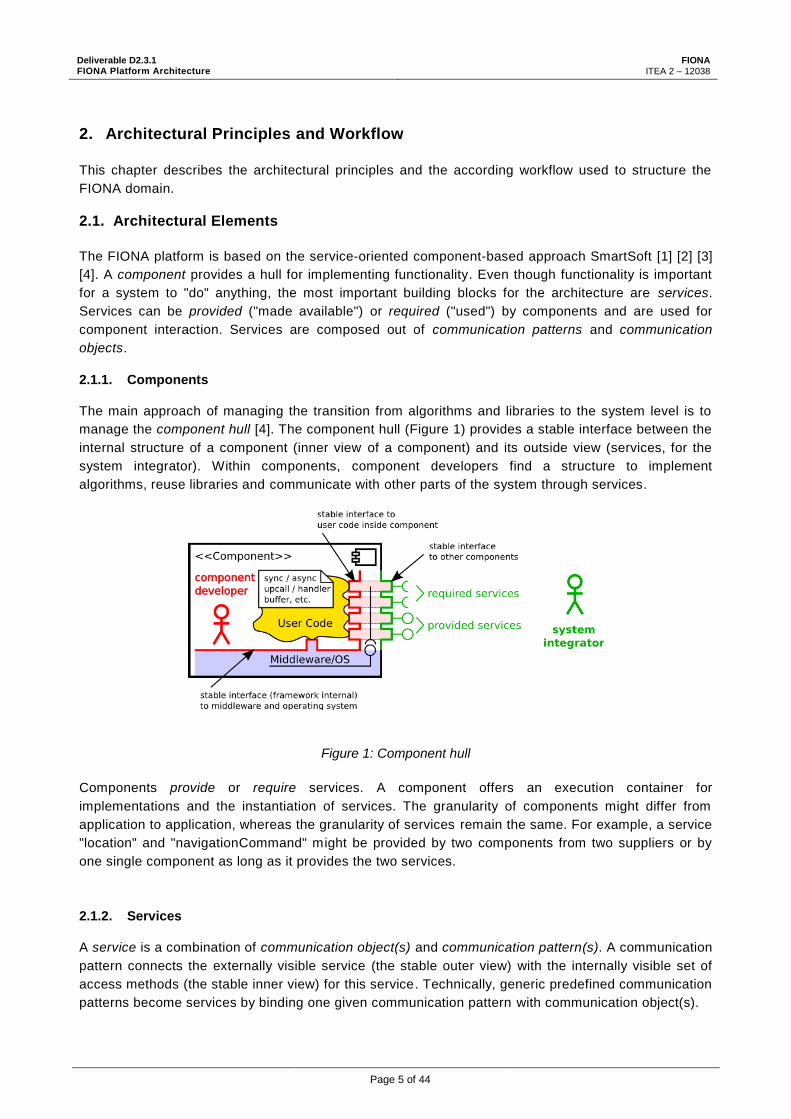
The main approach of managing the transition from algorithms and libraries to the system level is to
manage the component hull [4]. The component hull (Figure 1) provides a stable interface between the
internal structure of a component (inner view of a component) and its outside view (services, for the
system integrator). Within components, component developers find a structure to implement
algorithms, reuse libraries and communicate with other parts of the system through services.
Figure 1: Component hull
Components provide or require services. A component offers an execution container for
implementations and the instantiation of services. The granularity of components might differ from
application to application, whereas the granularity of services remain the same. For example, a service
"location" and "navigationCommand" might be provided by two components from two suppliers or by
one single component as long as it provides the two services.
2.1.2. Services
A service is a combination of communication object(s) and communication pattern(s). A communication
pattern connects the externally visible service (the stable outer view) with the internally visible set of
access methods (the stable inner view) for this service. Technically, generic predefined communication
patterns become services by binding one given communication pattern with communication object(s).

Deliverable D2.3.1 FIONA Platform Architecture
FIONA ITEA 2 – 12038
Page 6 of 44
2.1.3. Communication Pattern
Communication patterns [4] provide the only link of a component to its external world. They define the
semantics and policy of communication. By using a fixed set of communication patterns, the semantics
of the services of a component is predefined, irrespective of where the communication patterns are
applied. By knowing the communication pattern, the semantics and policy of this particular service of
the component is known. This supports and enables Separation of Roles (system integrator can rely on
the known pattern) and System Composition (services become exchangeable) where new applications
can be composed by reusing already existing software building blocks.
The Communication Patterns used to design the FIONA architecture are listed in Table 1. For further
reading, see [4], [5], [6].
Table 1: Communication Patterns
Patterns for communication
Send Client/server One-way communication
Query Client/server Two-way request/response
Push newest Publisher/subscriber 1-to-n distribution
Push timed Publisher/subscriber 1-to-n distribution
Patterns for component coordination and configuration
Event Client/server Asynchronous conditioned notification
Parameter Master/slave Run-time configuration
State Master/slave Lifecycle management and activation
Dynamic wiring Master/slave Dynamic connection wiring
Monitoring Master/slave Run-time monitoring of components
These communication patterns explicate several communication methods, such as one -way (send) or
request-response (query) interaction. Two push patterns provide publish/subscribe interaction on a
regular timely basis (push timed) or whenever updates are available (push newest). The event pattern
is used for asynchronous event notifications. The parameter pattern can be used in order to
parameterize and configure variation points of a component at runtime. The state pattern [5] is used for
selecting a processing state of the component (e.g. active, neutral) and is used for resource
management. The dynamic wiring pattern allows for dynamic rewiring of connections between
components at runtime. The monitoring pattern [7] is a generic concept for runtime monitoring that
provides means to gain insight into running components.
2.1.4. Communication Object
Communication Objects[4] define the data structure (content) to be transmitted via a communication
pattern between components. Communication objects are ordinary objects decorated with additional
member functions for data access and internal use by the framework.
An example of a nested communication object "CommBasePose" from the robotics domain is given in
Figure 2. It is used to provide a service that tells about the current pose of the robot in the world. Most
important, the communication object includes an attribute "pose3D" that represents a pose in 3D
space. It consists of 3D-position and 3D-orientation, therefore the communication object reuses two
other communication objects "CommPosition3d" (x-, y-, z-element of position) and

Deliverable D2.3.1 FIONA Platform Architecture
FIONA ITEA 2 – 12038
Page 7 of 44
"CommOrientation3d" (for azimuth/yaw-, elevation/pitch-, roll-element of orientation). A covariance
Matrix "covMatrix" represents the uncertainty of the mobile robot ( in x, y, azimuth).
Figure 2: Example of a (nested) communication object.
Besides attributes for communication, "CommBasePose" can define access methods. For example, the
communication object might provide access methods for coordinate system or unit conversion.
The following data types are available for attributes of the communication object:
Boolean
Double, Float
Int8, Int16, Int32, Int64
UInt8, UInt16, UInt32, UInt64
String
[N] - Array of any of the previous types. N can be an integer denoting the number of elements
or * for a flexible list
CommObjectRef(NAME) - to indicate a nested communication object
StructRef(NAME) - to indicate a nested Struct
EnumRef(NAME) - to indicate an enumeration usage.
Besides communication objects, the following data structures can be defined. However, they are not
for direct transmission between components but to assist in providing additional structure within a
communication object:
Enumeration
Struct
2.2. Workflow
Figure 3 illustrates the workflow that is used to develop the architecture of FIONA. It follows the
development use-case described in [8]. In a first step, services are defined (1), then they are reused
and aggregated to components in order to provide components and sub-architectures (2). The

Deliverable D2.3.1 FIONA Platform Architecture
FIONA ITEA 2 – 12038
Page 8 of 44
outcome is a generic FIONA architecture which provides a toolbox (2) out of which all applications
within the scope of FIONA can be composed (3).
Figure 3: FIONA architecture workflow and relations.
A Service-Oriented Software Component Model is a toolbox for designing architectures, such as the
FIONA architecture for the core functions of localisation and navigation in indoor and outdoor
environments. This FIONA architecture in turn provides a toolbox of services, architectural patterns
and components from which selected elements are reused and composed to concrete architectures for
applications. The demonstrators developed within the FIONA Project are examples for such concrete
applications.
2.2.1. SmartSoft
The service-oriented component-based approach SmartSoft provides the foundation for the FIONA
architecture (Figure 3, left, blue box). It provides structure, infrastructure and tool support at all levels
and steps. Amongst others, it includes:
Deliverable D2.3.1 FIONA Platform Architecture
FIONA ITEA 2 – 12038
Page 9 of 44
SmartMARS MetaModel. It defines the structure for communication objects, a set of
communication patterns, the structure of services and components, the structure for
deployment.
SmartSoft Framework and implementation. In its current state, two exchangeable
implementations (ACE and CORBA middlewares). Execution containers for several platforms
and operating systems.
SmartSoft MDSD Toolchain. An integrated MDSD toolchain for development that supports the
separation of roles. The toolchain covers the development process of modelling communication
objects, components and systems.
2.2.2. Service Definition
The first level "service definitions" (Figure 3: upper part, (1), orange) uses the structure provided by
SmartSoft to define Services that might be provided (made available) or required (relevant) in a
FIONA-application. Services are the basic architectural entities. They guarantee that supplied
components can be integrated into concrete applications (demonstrators). At the same time, they keep
the architecture and implementation containers flexible due to the service-level and component-level
abstractions. Further, they allow to identify white spots in the architecture as early as possible .
Services consist of communication objects (data structure/content) and communication patterns (how
this information is being communicated). At this level, the structure of communication objects is
defined (name of attributes, data types). A communication object together with a selected
communication pattern (out of a set of communication patterns defined in SmartSoft) becomes a
service.
For example, a location is a very fundamental data structure for every FIONA-application. Therefore, at
this level is defined what a "location" actually is, e.g. whether it is represented as full pose in 3D space
with Euler angles (x, y, z, yaw, pitch, roll, uncertainty), geographical position coordinates (latitude,
longitude, altitude, but without orientation), or even separate communication objects for both. It is also
defined that for example dynamic path planning needs a regularly or periodically updated location. A
location could therefore be updated every 0.2s (push timed pattern with period 0.2s).
The FIONA stakeholders contribute to service definitions by providing inputs in order to find the least
common denominator of communication objects that are relevant for the FIONA scope. The smaller
this set is, the better is the composability that can be achieved with building blocks (components)
that provide or require this service. SmartSoft provides structure to this level by a MetaModel and
the concept of services and is therefore a toolbox for finding the concrete services for FIONA.
2.2.3. Component Level
The second step focuses on aggregating services to components and to architectural patterns (Figure
3, orange box, (2)). Components or groups of components are defined. They provide or require the
services from (1). There might be competing alternative components providing the same services f rom
different suppliers with different characteristics. Both open source and closed source implementations
can be used since one can rely on service descriptions.
Deliverable D2.3.1 FIONA Platform Architecture
FIONA ITEA 2 – 12038
Page 10 of 44
For example, the common denominator for the core functionality of localisation could have been
defined in (1) as the communication object "pose for 3D space" (x, y, z, yaw, pitch, roll) that needs to
be pushed to subscribers. Now there might be alternative architectural patterns or components for
indoor localisation which consist of a different structure of components and are provided by 3rd party
component suppliers in a market. Use of these alternatives is feasible only because they provide the
same service ("periodically publish pose") that makes them exchangeable. For example, if outdoor
localisation provides the same service, it is part of the set of alternatives. These alternatives might
even be swapped at runtime.
FIONA stakeholders contribute to the architectural patterns from their field of expertise, however
having to meet the defined FIONA. The service definitions (1) therefore provide a toolbox for
architectural patterns (2). Again, this level conforms to the SmartSoft MetaModel which provides
structure in the form of components that can provide and require services from (1) and there fore
provide further structure to realize / implement them.
2.2.4. Concrete Application
Finally, there are concrete applications in the last step (Figure 3, bottom, yellow box (3)). When FIONA
users develop new applications within the FIONA domain, these applications can rely on service
definitions in order to either implement these services or reuse 3rd party imp lementations of these
services. For example, a FIONA demonstrator for iOS 7.0 to navigate and get information about
exhibits in the Deutsche Museum München running on an iPad 2 using a plug-in RGB camera of a
specific brand. Such applications can then be composed out of selected elements of the FIONA
general architecture (2). Compatibility is given by the definition of FIONA services (1) that cover the
core functions of localisation and navigation in indoor and outdoor areas.
SmartSoft also contributes to this level by providing an execution container for components. It maps
the component hull to the execution environment (operating system and processor architecture).
FIONA stakeholders contribute to this level by providing their components and implementations of (2)
and finalizing the demonstrators. Again, the elements of the generic architecture (2) provide a toolbox
for concrete FIONA applications (3).
At least two concrete FIONA applications and their concrete architectures are driven by the two
planned FIONA demonstrators addressing:
Personal navigation through an indoor area using a Smartphone (section 4)
Navigation assistance for the visually impaired (section 5)

Deliverable D2.3.1 FIONA Platform Architecture
FIONA ITEA 2 – 12038
Page 11 of 44
2.3. Further Reading and Resources
In addition to the chapter about SmartSoft in FIONA Deliverable D2.2.1 State of the Art on Service-
Oriented Software Component Models[9], the following resources provide further insights:
Model-Driven Software Development in Robotics: Communication Patterns as Key for a Robotics
Component Model [4]:
o Section 1 - Introduction
o Section 3.1 - The SmartSoft-Component
o Section 3.2 - The SmartSoft Communication Patterns
o Section 3.3 - Use-Cases of the Communication Patterns
o Section 4 - SmartSoft and CBSE
Model-Driven Software Systems Engineering in Robotics: Covering the Complete Life-Cycle of a
Robot [10]:
o Section 2.1 - Towards a Software Business Ecosystem in Robotics
o Section 3.1 - Software Component Model
o Section 3.5 - Reuse and Systems Integration
Service Robot Control Architectures for Flexible and Robust Real-World Task Execution: Best
Practices and Patterns[11]:
o Section 2 - Freedom from Choice vs. Freedom of Choice
o Section 3 - Best Practices in Designing System Architectures
Model-driven software systems engineering in robotics: Covering the complete life -cycle of a robot
[12]:
o Section 2 - Towards a software business ecosystem in robotics
o Section 3.1 - SmartSoft and SmartMDSD: A robotics software component model
SmartSoft Video/Screencast Tutorials
o A series of screencasts demonstrates the use of the SmartMDSD Toolchain. It can be used
as a walk-through tutorial through all stages of the development process and major
functionalities of the toolchain.
o Online: http://servicerobotik-ulm.de/drupal/?q=node/70
SmartSoft website (SmartMDSD Toolchain): http://www.servicerobotik-ulm.de

Deliverable D2.3.1 FIONA Platform Architecture
FIONA ITEA 2 – 12038
Page 12 of 44
3. FIONA Platform Architecture
This chapter describes how the FIONA Project applied the architectural principles and the workflow (as
described in section 2.2, see also [8]) in order to define concrete FIONA services.
The goal is to converge to the lowest common denominator of communication objects and services that
are relevant in the FIONA domain. The smaller this set is, the better is the composability that can be
achieved with building blocks (software components) that provide and require these services.
However, one can at the same time keep specific communication objects and specific services in order
to best exploit unique abilities and features of the software components. Finally, it is about finding the
right balance between "too specific" and "too general" in order to support composability while not
losing unique characteristics.
3.1. Software Architecture
This section lists a set of service descriptions clustered among relevant functional areas.
3.1.1. Sensors
GetIMU Provided Service Required Service
Description: The sensor data from IMU (accelerometer, gyroscope, magnetometer) is provided
Communication Pattern
Push Timed
Communication Object 1 (if query pattern, this is the request object)
Name: GetIMU
Content / Attributes:
Name: Data Type
Description Unit
Yaw_g Double Gyroscope: Rotation around Z-axis
Dps (degrees per second)
Roll_g Double Gyroscope: Rotation around X-axis
Dps
Pitch_g Double Gyroscope: Rotation around Y-axis
Dps
Out_x_ac Double Accelerometar: Linear speed X-axis
g
Out_y_ac Double Accelerometar: Linear speed Y-axis
g
Out_z_ac Double Accelerometar: Linear speed Z-axis
g
Out_x_m Double Magnetic range X-axis Gauss
Out_y_m Double Magnetic range Y-axis Gauss
Out_z_m Double Magnetic range Z-axis Gauss

Deliverable D2.3.1 FIONA Platform Architecture
FIONA ITEA 2 – 12038
Page 13 of 44
RFSignalRSSI Provided Service Required Service
Description: Received signal strength of a radio frequency signal transmitter
Communication Pattern
Push Timed
Communication Object 1 (if query pattern, this is the request object)
Name: RFSignalRSSI
Content / Attributes:
Name: Data Type
Description Unit
TransmitterID String Preferably the MAC ID
ReceiverID String Preferably the MAC ID
RFtype String “WiFi”, “15.4”, “BT”, “LTE”. Etc.
RSS Float Received signal strength dBm
T Int64 Timestamp (absolute time) ms
RFTOA Provided Service Required Service
Description: RF signal time of arrival from one transmitter to a receiver
Communication Pattern
Push Timed
Communication Object 1 (if query pattern, this is the request object)
Name: RFTOA
Content / Attributes:
Name: Data Type
Description Unit
TransmitterID String Preferably the MAC ID
ReceiverID String Preferably the MAC ID
TOA double Time of Arrival s
T Int64 Timestamp (absolute time) ms

Deliverable D2.3.1 FIONA Platform Architecture
FIONA ITEA 2 – 12038
Page 14 of 44
RFAOA Provided Service Required Service
Description: RF signal angle of arrival. Currently this angle is azimuthal angle with respect to earth North or a reference direction. If there is a need for derive elevation from angle of arrival, the representation of angle can be extended to azimuth and altitude.
Communication Pattern
Push Timed
Communication Object 1 (if query pattern, this is the request object)
Name: RFAOA
Content / Attributes:
Name: Data Type
Description Unit
DeviceID String Preferably the MAC ID
ReceiverID String Preferably the MAC ID
AOA Double Azimuth angle of arrival degree
T Int64 Timestamp (absolute time) ms
Satellite in View Provided Service Required Service
Description: Satellite in view coordinate in ecef(earth-centered earth-fixed), and satellite range
Communication Pattern
Push Timed
Communication Object 1 (if query pattern, this is the request object)
Name: SVi
Content / Attributes:
Name: Data Type
Description Unit
SatelliteID String SatelliteID
X_ecef Int32 Satellite X coordinate in ecef meter
Y_ecef Int32 Satellite Y coordinate in ecef meter
Z_ecef Int32 Satellite Z coordinate in ecef meter
range Int32 Distance from satellite to receiver
meter
T Int64 Timestamp (absolute time) ms

Deliverable D2.3.1 FIONA Platform Architecture
FIONA ITEA 2 – 12038
Page 15 of 44
GyroscopeInput Provided Service Required Service
Description: Gyroscope reading. (Accelerometer, gyro, and magnetometer inputs are separated due to their different update rate.)
Communication Pattern
Push Timed
Communication Object 1 (if query pattern, this is the request object)
Name: GyroInput
Content / Attributes:
Name: Data Type
Description Unit
DeviceID String Preferably the MAC ID
yaw Double Gyro rotation around Z axis Deg/s
pitch Double Gyro rotation around Y axis Deg/s
roll Double Gyro rotation around X axis Deg/s
T Int64 Timestamp (absolute time) ms
MagnetometerInput Provided Service Required Service
Author: Bosch
Description: Magnetometer input. (Accelerometer, gyro, and magnetometer inputs are separated due to their different update rate.)
Communication Pattern
Push Timed
Communication Object 1 (if query pattern, this is the request object)
Name: MagInput
Content / Attributes:
Name: Data Type
Description Unit
DeviceID String Preferably the MAC ID
x Double Magnetometer x direction Gauss
y Double Magnetometer y direction Gauss
z Double Magnetometer z direction Gauss
T Int64 Timestamp (absolute time) ms

Deliverable D2.3.1 FIONA Platform Architecture
FIONA ITEA 2 – 12038
Page 16 of 44
ImageInput Provided Service Required Service
Description: Image sensor reading
Communication Pattern
Event
Communication Object 1 (if query pattern, this is the request object)
Name: ImageInput
Content / Attributes:
Name: Data Type
Description Unit
DeviceID String
ImageSize Uint16[2] X by Y pixels
Image Double[ImageSize]
Image data
updateFrequency float Update frequency Hz
T Int64 Timestamp (absolute time) ms
ibeaconlistProvider Provided Service Required Service
Description: Provides a list of beacons within range.
Communication Pattern
Push Newest
Communication Object 1 (if query pattern, this is the request object)
Name: CommiBeaconList
Content / Attributes:
Name: Data Type Description Unit
beaconList CommiBeacon[*]
CommiBeacon:
Name: Data Type Description Unit
Uuid Int32 The Uuid of the beacon
Major Int32 The Major ID of the beacon
Minor Int32 The Minor ID of the beacon
Rssi Float RSSI value / received signal strengh
db
txPower Float Measured power of the signal at a distance of 1m
db
Distance Float Calculated distance between beacon and receiver
M

Deliverable D2.3.1 FIONA Platform Architecture
FIONA ITEA 2 – 12038
Page 17 of 44
3.1.2. Environment Perception
PointObjectDetected Provided Service Required Service
Description: Point object (without volume) detected in Region of Interest. This may be the nearest point on a solid object to the user
Communication Pattern
Push Newest
Communication Object 1 (if query pattern, this is the request object)
Name: PointObjectLocation
Content / Attributes:
Name: Data Type
Description Unit
ObjID UInt16 ID of detected object
PositionX Float With respect to a reference position
meter
PositionY Float With respect to a reference position
meter
PositionZ Float Can be left empty if not available
meter
Confidence float Confidence level (error level) meter
T Int64 Time of the recorded location ms
VolumeObjectDetected Provided Service Required Service
Description: Volume object (i.e. with extent) detected in Region of Interest
Communication Pattern
Push Newest
Communication Object 1 (if query pattern, this is the request object)
Name: VolumeObjectLocation
Content / Attributes:
Name: Data Type
Description Unit
ObjID UInt16 ID of detected object
PositionX Float With respect to a reference position
meter
PositionY Float With respect to a reference position
meter
PositionZ Float Can be left empty if not available
meter
Confidence float Confidence level (error level) meter
T Int64 Time of the recorded location ms

Deliverable D2.3.1 FIONA Platform Architecture
FIONA ITEA 2 – 12038
Page 18 of 44
obstacleProvider Provided Service Required Service
Description: Provide information/warning about a detected obstacle on the near floor. The warning will only contain information, whether a obstacle is present or not. The information will be made available as soon as the state changes, i.e. the object appears or disappears. No information about the further nature or the size of the obstacle will be provided.
Communication Pattern
Push Newest
Communication Object 1 (if query pattern, this is the request object)
Name: CommObstacle
Content / Attributes:
Name: Data Type
Description Unit
Obstacle Boolean Obstacle present? false: no obstacle present true: obstacle present
3.1.3. Localization
orientationProvider Provided Service Required Service
Description: This service provides the 3D orientation of the device relative to magnetic north.
Communication Pattern
Push Timed
Communication Object 1 (if query pattern, this is the request object)
Name: CommOrientation
Content / Attributes:
Name: Data Type Description Unit
Yaw,pitch,roll double Euler representation of the orientation. x pointing to magn. north, z to zenit. Right hand coordinate system. 0 to 2π. Rotation yaw->pitch->roll: successive rotations around local (dynamic) axes in z,y,x order
rad
confidence Double[9] 3x3 Covariance matrix
Is_valid Boolean True/false --

Deliverable D2.3.1 FIONA Platform Architecture
FIONA ITEA 2 – 12038
Page 19 of 44
locationProvider Provided Service Required Service
Description: This service provides the 6D Location of the device, consisting of two parts: 3D position and 3D orientation.
Communication Pattern
Push Timed
Communication Object 1 (if query pattern, this is the request object)
Name: CommLocation
Content / Attributes: CommLocation:
Name: Data Type Description Unit
position CommPosition Position-part, xyz coordinates --
orientation CommOrientation Orientation-part --
is_valid Boolean True/false --
CommPosition:
Name: Data Type
Description Unit
X,y Double Cartesian coordinates in meters along with an reference point in WGS84 (gps latitude/longitude in decimal degrees) plus heading with respect to true north.
meter
z double If indoors, z scales between floors in the European way. e.g. 1 is first floor above ground, 1.5 is an intermediate level/staircase between 1st and 2nd floor
levels
reference_lat, reference_long, reference_alt
double Reference to the position in WGS84 Decimal degrees
reference_heading
double Reference rotation with respect to true north
Degree
confidence Double[9] 3x3 Covariance matrix
Is_valid Boolean True/false --
CommOrientation, see Orientation Service

Deliverable D2.3.1 FIONA Platform Architecture
FIONA ITEA 2 – 12038
Page 20 of 44
3.1.4. Navigation
rasterMapProvider Provided Service Required Service
Description: This service provides raster map with respect to given floor number, crop information and user profile. It provides profile dependent map generated by Map component.
Communication Pattern
Query
Communication Object 1
Name: CommRasterMapRequest
Content / Attributes:
Name: Data Type Description Unit
user_name String User name
map_name String Name of the requested raster map. Map Name Convention: Map name should end with floor number s convention. Ex: <mapnameX.png>
map_crop_ul_lon Double Upper Left Crop Point Longitude coordinate All Long. and Lat. value are 0 if whole raster map is requested.
degree
map_crop_ul_lat Double Upper Left Crop Latitude coordinate point All Long. and Lat. value are 0 if whole raster map is requested
degree
map_crop_lr_lon Double Lower Right Crop Longitude coordinate point All Long. and Lat. value are 0 if whole raster map is requested
degree
map_crop_lr_lat Double Lower Right Crop Latitude coordinate point All Long. and Lat. value are 0 if whole raster map is requested
degree
Communication Object 2
Name: CommRasterMap
Content / Attributes:
Name: Data Type Description Unit
user_name String User Name
map_name String Name of the raster map that is requested.
map_raster_file_url String File location of Raster Map (It may be a web url.)
map_grid_data CommGridMap Smartsoft Grid Data of Map

Deliverable D2.3.1 FIONA Platform Architecture
FIONA ITEA 2 – 12038
Page 21 of 44
rasterMapInfoProvider Provided Service Required Service
Description: This service is used to query map information. This service might be used by GUI when necessary.
Communication Pattern
Query
Communication Object 1
Name: CommRasterMapInfoRequest
Content / Attributes:
Name: Data Type
Description Unit
map_name String Name of the requested raster map. Map Name Convention: Map name should end with floor number s convention. Ex: <mapnameX.png>
Communication Object 2
Name: CommRasterMapInfo
Content / Attributes:
Name: Data Type
Description Unit
map_name String Name of the requested raster map. Map name should end with floor number.Ex: <mapnameX.png>
map_crop_ul_lon Double Upper Left Crop Point Longitude coordinate All Long. and Lat. value are 0 if whole raster map is requested.
degree
map_crop_ul_lat Double Upper Left Crop Latitude coordinate point All Long. and Lat. value are 0 if whole raster map is requested
degree
map_crop_lr_lon Double Upper Left Crop Longitude coordinate point All Long. and Lat. value are 0 if whole raster map is requested
degree
map_crop_lr_lat Double Upper Left Crop Latitude coordinate point All Long. and Lat. value are 0 if whole raster map is requested
degree
grid_x_size Int32 Number of columns in pixel for a given grid
Pixel
grid_y_size Int32 Number of rows in pixel for a given grid
Pixel
raster_x_size Int64 Width of map Pixel
raster_y_size Int64 Height of map Pixel

Deliverable D2.3.1 FIONA Platform Architecture
FIONA ITEA 2 – 12038
Page 22 of 44
CoordinateConversion Provided Service Required Service
Description: This service is used to convert coordinates between map and real world reference coordinate systems.
Communication Pattern
Query
Communication Object 1
Name: CommCoordConvRequest
Content / Attributes:
Name: Data Type
Description Unit
map_name String Name of the requested raster map. Map name should end with floor number.Ex: <mapnameX.png>
coord_type Enum E_GEOGRAPHIC: Map to Real World Coordinate Conversion E_SYNTHETIC: Real World to Map Coordinate Conversion
coord_x Double Either pixel x coordinate or map lon coordinate depending on coord_type
coord_y Double Either pixel y coordinate or map lat coordinate depending on coord_type
Communication Object 2
Name: CommCoordConv
Content / Attributes:
Name: Data Type
Description Unit
map_name String Name of the requested raster map. Map Name Convention: Map name should end with floor number s convention. Ex: <mapnameX.png>
coord_conv_x Double Either pixel x or map lon converted coordinate depending on coord_type
coord_conv_y Double Either pixel y or map lat converted coordinate depending on coord_type

Deliverable D2.3.1 FIONA Platform Architecture
FIONA ITEA 2 – 12038
Page 23 of 44
destinationProvider Provided Service Required Service
Description: This service sends a destination request for navigation. It can be used to initiate navigation to a desired destination. The destination should be provided only if a new destination is selected (e.g. from user interface)
Communication Pattern
Send
Communication Object 1 (if query pattern, this is the request object)
Name: CommDestination
Content / Attributes:
Name: Data Type Description Unit
user_name string User name
destination CommPosition Destination, see CommPosition
pathProvider Provided Service Required Service
Description: Provides the complete path to destination, based on the current location. The path is specified by a list of waypoints (CommPosition) that lead to the destination.
Communication Pattern
Push Newest
Communication Object 1 (if query pattern, this is the request object)
Name: CommPath
Content / Attributes:
Name: Data Type Description Unit
waypoints CommPosition[*] See CommPosition
Is_valid Boolean True/false

Deliverable D2.3.1 FIONA Platform Architecture
FIONA ITEA 2 – 12038
Page 24 of 44
3.1.5. Security
authenticationProvider Provided Service Required Service
Description: Provides authentication check with username and password.
Communication Pattern
Query
Communication Object 1 (if query pattern, this is the request object)
Name: CommAuthenticationRequest
Content / Attributes:
Name: Data Type
Description Unit
username String The username
password String The password
Communication Object 2 (if query pattern, this is the reply pattern. If not query pattern, please leave blank)
Name: CommAuthenticationResponse
Content / Attributes:
Name: Data Type
Description Unit
accessGranted boolean True=granted, false=denied

Deliverable D2.3.1 FIONA Platform Architecture
FIONA ITEA 2 – 12038
Page 25 of 44
3.1.6. Human Machine Interaction
LocalPath Provided Service Required Service
Description: Information about the next turn
Communication Pattern
Push newest
Communication Object 1 (if query pattern, this is the request object)
Name: NextTurn
Content / Attributes:
Name: Data Type
Description Unit
DistanceToTurn Uint16 Distance to the next turn mm
TypeOfTurn Enum Type of turn, e.g. left, right, sharp left – maybe enumerated as hours on a clock face (e.g. “4” is sharp right, “9” is left)
profileProvider Provided Service Required Service
Description: This service broadcasts user profile information of the user currently using the device. For each user, the profile contains:
routing preferences (e.g. avoid stairs, visit outlooks, stay indoors, avoid elevators)
o use_elevator o use_stairs o use_outdoor_navigation
landmarks (points of attention that help vis. impaired, in coordinates)
access level of user (authentication level)
Map_list (list of floors of current map)
Communication Pattern
Query
Communication Object 1 (if query pattern, this is the request object)
Name: CommUserProfileRequest
Content / Attributes:
Name: Data Type
Description Unit
user_name String User name
Communication Object 2 (if query pattern, this is the reply pattern. If not query pattern, please leave blank)
Name: CommUserProfileReply
Content / Attributes:
Name: Data Type Description Unit
user_name String User name
authentication_level Int8 10 Levels of authentications. The higher the level, more privilege the user has.
use_elevator Boolean Whether the user can use elevator to pass upstairs or downstairs
use_stairs Boolean Whether the user can use

Deliverable D2.3.1 FIONA Platform Architecture
FIONA ITEA 2 – 12038
Page 26 of 44
stairs to pass upstairs or downstairs
Map_list String[*] List of floors of current environment.
landmark_list String[*] List of landmarks selected by the user. This is list of user points of attention
use_outdoor_navigation Boolean Whether the user prefers staying inside the building. 0: Only Indoor Navigation 1: Both Indoor and Outdoor Navigation

Deliverable D2.3.1 FIONA Platform Architecture
FIONA ITEA 2 – 12038
Page 27 of 44
Points of Attention Provided Service Required Service
Description: The user should e ale to select a-priori points of interest. He/she will be given a notification when passing one of the poits.
Communication Pattern
Query
Communication Object 1 (if query pattern, this is the request object)
Name: RequestPointsOfAttention
Content / Attributes:
Name: Data Type
Description Unit
Points of Attention List of Integers (2 x n)
A list of (x,y) coordinates for certain points of attention that are specified by the (blind) users. Coordinates need to be aligned with the map coordinates.
m

Deliverable D2.3.1 FIONA Platform Architecture
FIONA ITEA 2 – 12038
Page 28 of 44
3.2. Hardware Architecture
The diversity of hardware components is huge and there is an enormous variety of hardware
components that might be chosen for building a concrete application. Furthermore, hardware
components often only have short life-cycles until they become replaced by another generation that is
cheaper, consumes less energy, has a smaller footprint, provides more accuracy or provides more
computational power etc. In order to be able to select the best fitting hardware components, one
typically needs to know the design goals and requirements of a very specific application. For example,
given a very concrete use-case, one can balance processing power versus energy consumption versus
costs.
Thus, the FIONA architecture will not establish a single hardware reference architec ture or a toolbox
covering all kinds of hardware devices. Instead, it provides abstractions such that different hardware
platforms can be supported and that different kinds of hardware devices like different sensors can be
integrated easily.
The first abstraction is based on the communication objects that transform sensor-specific values into
more generic data sets e.g. based on standard SI units and with covariance values to express
uncertainty. A hardware specific sensor driver component manages the sensor and offers its values as
a standardized service with the standardized communication object such that all other components can
be reused when the hardware sensor is replaced. Following this approach, it doesn't matter anymore
which kind of specific hardware provides sensor readings, e.g. acceleration values.
The second abstraction is based on the execution container that hosts components and prevents lock -
ins into vendor-specific frameworks. The execution container provides stable interfaces for FIONA
components and should be mappable onto different operating systems. For example, SmartSoft
components have been successfully run on different architectures (i386, ARM) and operating systems
(Linux, Windows, iOS, Mac OS) using different communication middlewares (ACE, CORBA) [13].
The FIONA architecture leaves space for integrating hardware by either providing the execution
containers to (computational) hardware platforms or by transforming hardware specific sensor values
into standardized services.
SmartSoft has already been shown to cover the needs of a large variety of possible FIONA platforms
and provides the possibility to be adapted in a transparent way to new platforms. Given the current
state of the SmartSoft execution container, there is no risk in first focusing on standard Linux
platforms, since it allows the integration of specialized hardware and hardware device prototypes and
reduces the effort and risk for implementing FIONA prototypes and demonstrators.

Deliverable D2.3.1 FIONA Platform Architecture
FIONA ITEA 2 – 12038
Page 29 of 44
3.3. Equipping the SmartMDSD Toolchain with FIONA Architectural Elements
The previous section 3.1 used the generic concepts of the service-oriented component-based
approach SmartSoft to structure the FIONA domain. While these structures are described on a
conceptual level, the SmartMDSD Toolchain provides the tooling and infrastructure to use and realize
the generic concepts of SmartSoft and apply them to the FIONA architectural elements such that they
become available for immediate (re)use as a toolbox for FIONA users in their different roles.
The SmartMDSD Toolchain as an Integrated Development Environment (IDE) software development
applying the service-oriented component-based approach SmartSoft. The SmartMDSD Toolchain uses
concepts of Model-Driven Software Development (MDSD) based on Eclipse. It combines a set of
dedicated graphical and textual (modeling) tools in one integrated toolchain that guides the
stakeholders through the development workflow and makes concepts and methods of the SmartSoft
world accessible to its users.
Equipping the SmartMDSD Toolchain with the FIONA-specific architectural elements from section 3.1
creates a development toolbox for FIONA. As a result, FIONA users can benefit of the integrated
development environment (IDE) and build composable and reusable components for the FIONA
domain according to the FIONA development process as described in [8].
This section shows the steps of equipping the SmartMDSD Toolchain with FIONA architectural
elements. It is shown how a component for localization is created and how it is used to compose an
instance of the FIONA architecture using the early demonstrator of Hochschule Ulm "Mobile navigator
through an indoor environment" as an example.

Deliverable D2.3.1 FIONA Platform Architecture
FIONA ITEA 2 – 12038
Page 30 of 44
3.3.1. Modeling FIONA Building Blocks
This section will first model communication objects, then reuse them for modeling a component that
provides a service. A service consists of one communication object, one communication pattern (from
set of fixed patterns from SmartSoft) and optional additional properties that describe application-
related information of a service. Services are provided or required by components that run algorithms
and can be composed to applications.
First, the communication object is modeled in the SmartMDSD Toolchain (Figure 4):
Figure 4: Modeling of a communication object. Here: Location consisting of position and orientation
This step is necessary only once. Once the communication object is modeled, it is available for
immediate reuse for components to provide services. Communication patterns exist within the
SmartMDSD Toolchain and can be selected when modeling a component. Figure 5 shows the
modeling of SmartBluetoothLocalization component within the SmartMDSD Toolchain. It provides a
localization service ("locationProvider", section 3.1.3).

Deliverable D2.3.1 FIONA Platform Architecture
FIONA ITEA 2 – 12038
Page 31 of 44
Figure 5: Modeling of the component "SmartBluetoothLocalization" of Hochschule Ulm
The SmartMDSD Toolchain provides a complete IDE for implementing the component. The code
generator generates the hull of the component that is ready for implementing algorithms and
functionalities, in this example for a localization algorithm. Figure 6 shows how the services are used
from within the component implementation.
Figure 6: Using services from within a component implementation
Communication Patterns
Reuse of Communication Object
location Service

Deliverable D2.3.1 FIONA Platform Architecture
FIONA ITEA 2 – 12038
Page 32 of 44
3.3.2. Composing the HSU iBeacon Demonstrator
Applications can be composed of components that reuse the FIONA architecture elements. The early
demonstrator "Mobile navigator through an indoor environment" of Hochschule Ulm (HSU) was built
using the described approach by using components from the Hochschule Ulm Component repository.
In this demonstrator, a user is guided to rooms of Hochschule Ulm with the help of a tablet computer.
The tablet displays the building floor plan and visualizes the current user location and path to the
destination. Simple navigation instructions are given with a directed arrow that points along the path. A
video is available at http://youtu.be/G6fwnBAtyNc (published 14.10.2014). Localization is done using
iBeacons. Components run on a laptop carried in a bag pack (Figure 7). The user interacts with the
system using the tablet only (Figure 8).
Figure 7: The HSU Demonstrator
Using the SmartMDSD Toolchain, the demonstrator was put together by reusing components that were
developed using the described FIONA development process.
SmartBluetoothBeaconServer - Receives beacon transmissions
SmartBluetoothLocalization - Localization based on iBeacons
SmartSymbolicPlanner - A component that wraps symbolic planning mechanisms
SmartFionaNavigation - Can plan paths through the building using the symbolic planner
component
SmartWebInterface - Communicates with a web server to provide a web GUI to the user
The components are reused and assembled using the SmartMDSD Toolchain. Figure 9 shows the
system configuration of the demonstrator.

Deliverable D2.3.1 FIONA Platform Architecture
FIONA ITEA 2 – 12038
Page 33 of 44
Figure 8: Graphical user interface on the tablet
Figure 9: Deployment Diagram of HSU Demonstrator

Deliverable D2.3.1 FIONA Platform Architecture
FIONA ITEA 2 – 12038
Page 34 of 44
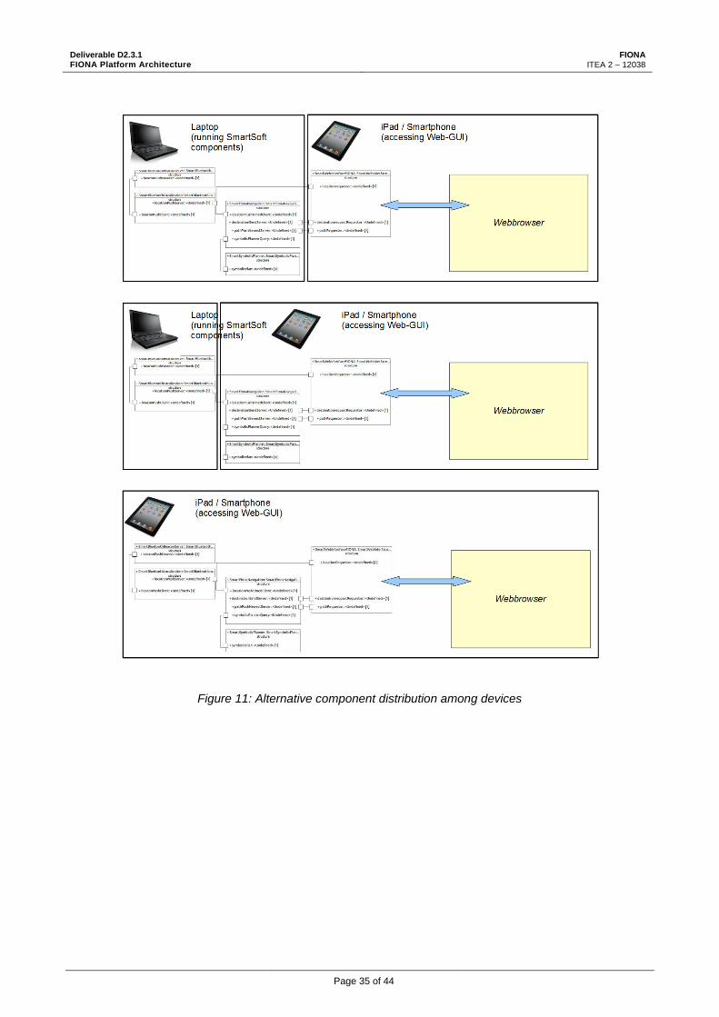
3.3.3. Possible variations
The prototypic demonstrator was set up as shown in Figure 10. All components are running on the
laptop. A web browser on the tablet communicates with the web interface component using WLAN. As
argued in section 3.2, components can transparently be distributed among devices as shown in Figure
11.
Figure 10: Component distribution of the HSU demonstrator. All components are running on the laptop.
Deliverable D2.3.1 FIONA Platform Architecture
FIONA ITEA 2 – 12038
Page 35 of 44
Figure 11: Alternative component distribution among devices

Deliverable D2.3.1 FIONA Platform Architecture
FIONA ITEA 2 – 12038
Page 36 of 44
Thanks to the service-oriented component-based approach and the support of the SmartMDSD
toolchain, it is possible to quickly build new applications or modifying existing ones. For example, the
component providing a localization service using iBeacons can be exchanged by a simulator
component (Figure 12) that provides localization based on ground truth of a simulator. Such a
component is available for reuse from the HSU component repository for use with the MORSE
simulator that also includes a building model of parts of Hochschule Ulm (Figure 13). A video
demonstrating the composition of this sub-demonstrator is available online:
https://youtu.be/qdetfVMP9is.
Figure 12: Alternative composition of the HSU demonstrator for use with the MORSE simulator
Figure 13: Using the MORSE simulator with the HSU demonstrator

Deliverable D2.3.1 FIONA Platform Architecture
FIONA ITEA 2 – 12038
Page 37 of 44
4. FIONA Demonstrator 1 Architecture: "Smartphone Navigator"
This chapter provides details of the architecture for the demonstrator "personal navigation through an
indoor area using a Smartphone". This architecture is a special instance of the generic architecture
and principles as described.
4.1. Software Architecture
Figure 14 shows components of the planned demonstrator and which services they aggregate. The
service names of provided services relate to service descriptions from section 3. Further descriptions
of components can be found in [8].

Deliverable D2.3.1 FIONA Platform Architecture
FIONA ITEA 2 – 12038
Page 38 of 44
cm
p A
rch
ite
ctu
re
Lo
ca
liza
tio
n (
on
e o
f th
ese
co
mp
on
en
ts i
s u
sed
wit
hin
a d
em
on
stra
tor
run
;
co
mp
on
en
ts a
re a
lte
rna
tive
s)
Lo
ca
liza
tio
n (
on
e o
f th
ese
co
mp
on
en
ts i
s u
sed
wit
hin
a d
em
on
stra
tor
run
;
co
mp
on
en
ts a
re a
lte
rna
tive
s)
Ori
en
tati
on
(o
ne
of
the
se c
om
po
ne
nts
is
use
d w
ith
in a
de
mo
nst
rato
r ru
n;
co
mp
on
en
ts a
re a
lte
rna
tive
s)
Ori
en
tati
on
(o
ne
of
the
se c
om
po
ne
nts
is
use
d w
ith
in a
de
mo
nst
rato
r ru
n;
co
mp
on
en
ts a
re a
lte
rna
tive
s)
Le
ge
nd
Sm
art
Se
ns
orD
ata
Fu
sio
n (
ES
K)
ori
en
tati
on
Pro
vid
er
Co
mp
on
en
t
serv
ice
th
at
pro
vid
es
da
ta
serv
ice
th
at
req
ure
s d
ata
<<
Co
mm
un
icatio
n P
att
ern
>>
Co
mm
un
icatio
n O
bje
ct(
s)
... S
ee D
2.3
.1 f
or
deta
iled
desc
rip
tio
ns
of
serv
ices
<<
Pu
shTim
ed
>>
Co
mm
Orien
tatio
n
Sm
art
Vis
ua
lLo
ca
liza
tio
n (
Co
mla
nd
)
loca
tio
nP
rovid
er
Sm
art
iBe
ac
on
Lo
ca
liza
tio
n (
Bo
sc
h)
loca
tio
nP
rovid
er
ori
en
tati
on
Re
qu
est
or
Sm
art
Se
cu
rity
(In
fin
eo
n)
au
the
nti
ca
tio
nP
rovid
er
Sm
art
Pa
thP
lan
nin
g (
Ha
ve
lsa
n)
pa
thP
rovid
er
loca
tio
nR
eq
ue
sto
r
rast
erM
ap
Re
qu
est
or
de
stin
ati
on
Re
qu
est
or
pro
file
Re
qu
est
or
<<
Pu
shTim
ed
>>
Co
mm
Lo
catio
n
<<
Pu
shTim
ed
>>
Co
mm
Lo
catio
n
<<
Pu
shN
ew
est
>>
Co
mm
Path
Co
mp
on
en
t re
qu
ires
a m
ap
fo
r p
ath
pla
nn
ing
fro
m w
hic
h it
is k
no
wn
wh
ich
grid
s are
access
ible
/in
access
ible
fo
r th
e u
ser.
Mo
tio
n c
om
man
d lo
gic
sh
ou
ld b
e e
mb
ed
ded
in
HM
I co
mp
on
en
t. T
his
co
mp
on
en
t
pro
vid
es
a lis
t o
f w
ayp
oin
ts.
Path
pla
nn
ing
do
es
no
t co
nsi
der
dyn
am
ic o
bst
acle
s (s
uch
as
bo
xes
on
th
e g
rou
nd
,
ch
airs
as
well
as
peo
ple
cro
ssin
g). I
t o
nly
co
nsi
ders
in
frast
ructu
re: w
alls
, d
oo
rs, st
airs,
etc
.. M
ap
is
no
t u
pd
ate
d d
urin
g r
un
tim
e, i.e
. o
bst
acle
s are
no
t ad
ded
to
map
an
d a
re
there
fore
no
t co
nsi
dere
d f
or
path
pla
nn
ing
.
Re-R
ou
tin
g:
No
way t
o in
itia
lize a
re-r
ou
tin
g v
ia a
serv
ice. R
e-r
ou
tin
g is
do
ne a
uto
matically
as
soo
n
as
there
is
a s
ho
rter/
bett
er
path
. Typ
ically
, th
is is
the c
ase
wh
en
th
e u
ser
takes
the
wro
ng
tu
rn.
=>
re-r
ou
tin
g if
path
is
blo
cked
by a
n o
bst
acle
is
no
t co
nsi
dere
d a
use
-case
in
path
pla
nn
ing
Path
will
be c
alc
ula
ted
as
a lis
t o
f g
rid
s. T
o t
he o
uts
ide, th
e g
rid
in
form
atio
n w
ill b
e
tran
sfo
rmed
to
co
ord
inate
s th
at
will
po
int
to t
he c
en
ter
of
the g
rid
s. T
his
will
use
th
e
rep
rese
nta
tio
n o
f "l
ocatio
n".
Sm
art
We
bIn
terf
ac
e (
Ulm
et
al)
rast
erM
ap
Re
qu
est
or
loca
tio
nR
eq
ue
sto
r
de
stin
ati
on
Pro
vid
er
pa
thR
eq
ue
sto
r
au
the
nti
ca
tio
nR
eq
ue
sto
r
- C
om
po
nen
t p
rovid
es
a G
UI
that
can
be
dis
pla
yed
on
th
e s
mart
ph
on
e/t
ab
let. C
alc
ula
tes
navig
atio
n in
stru
ctio
ns
base
d o
n w
ayp
oin
ts (
e.g
.
an
gle
of
arr
ow
base
d o
n g
oal an
d c
urr
en
t
locatio
n)
Sh
ow
s:
- M
ap
- Lis
t o
f ro
om
s fo
r se
lectio
n o
f d
est
inatio
n
- O
rien
tatio
n o
f u
ser
- A
rro
w t
o n
ext
wayp
oin
t o
n p
ath
Sm
art
Po
se
Es
tim
ati
on
(C
ze
ch
Co
ns
ort
ium
)
ori
en
tati
on
Pro
vid
er
<<
Pu
shTim
ed
>>
Co
mm
Orien
tatio
n
<<
Pu
shN
ew
est
>>
Co
mm
Dest
inatio
n
Sm
art
Ma
pP
rov
ide
r (H
av
els
an
)
rast
erM
ap
Pro
vid
er
<<
Qu
ery
>>
req
uest
: C
om
mR
ast
erM
ap
Req
uest
resp
on
se: C
om
mR
ast
erM
ap
<<
Qu
ery
>>
req
uest
: C
om
mA
uth
en
ticatio
nR
eq
uest
resp
on
se: C
om
mA
uth
en
ticatio
nR
esp
on
se
Sm
art
Pro
file
Pro
vid
er
(Ha
ve
lsa
n)
pro
file
Pro
vid
er
<<
Qu
ery
>>
req
uest
: C
om
mU
serP
rofile
Req
uest
resp
on
se: C
om
mU
serP
rofile
Rep
ly
Will
in
tern
ally
access
TP
M, P
AM
, ...
an
d w
ill d
o a
uth
en
ticatio
n b
ase
d o
n u
ser/
pass
wo
rd.
Map
is
inte
rnally
lo
ad
ed
fro
m f
ile a
nd
pro
vid
ed
via
a s
erv
ice t
o o
ther
co
mp
on
en
ts.
Map
serv
ice p
rovid
es
grid
/pix
el m
ap
to
dis
pla
y t
he m
ap
on
HM
I.
Th
e u
ser
pro
file
is
read
fro
m f
ile.
Sto
ry: Th
e u
ser
pro
file
is
fixed
at
start
up
an
d n
ot
ch
an
ged
at
run
tim
e.
- W
ill p
rovid
e u
ncert
ain
ty/c
on
fid
en
ce.
- W
ill in
tern
ally
access
co
nfig
ura
tio
n f
ile w
ith
po
sitio
ns
an
d I
Ds
of
beaco
ns.
Th
is f
ile w
as
pre
vio
usl
y c
reate
d d
urin
g s
etu
p.
- W
ill in
tern
ally
use
USB
-do
ng
le t
o a
ccess
iB
eaco
ns.
- W
ill u
se in
pu
t o
f a c
olo
r im
ag
e.
- W
ill p
rovid
e u
ncert
ain
ty f
or
locatio
n a
nd
orien
tatio
n.
- In
tern
ally
lo
ad
s a 3
D m
od
el o
f th
e b
uild
ing
th
at
was
pre
vio
usl
y g
en
era
ted
(u
sin
g a
dep
th c
am
era
) b
y t
he
too
l/m
eth
od
develo
ped
by C
om
lan
d.
Inte
rnally
access
es
orien
tatio
n d
evic
e a
nd
pro
vid
es
orien
tatio
n
to t
he s
yst
em
.
- In
tern
ally
read
s se
rial d
ata
fro
m E
SK
sen
sor
fusi
on
develo
pm
en
t b
oard
an
d p
rovid
es
the o
rien
tatio
n t
o t
he
syst
em
.
- C
alib
ratio
n w
ill b
e d
on
e o
nce a
fter
inte
gra
tio
n in
to t
he
dem
on
stra
tor
is d
on
e.
- ESK
will
leave u
ncert
ain
ty u
nse
t in
th
e s
erv
ice.
Figure 14: Software architecture of demonstrator 1

Deliverable D2.3.1 FIONA Platform Architecture
FIONA ITEA 2 – 12038
Page 39 of 44
4.2. Hardware Architecture
The FIONA Demonstrator Device consists of a Laptop carried by the user, e.g. in a bag pack (Figure
15 and Figure 7). The sensors are attached to the Laptop. The user interacts with the system using a
Smartphone or tablet PC.
The illustrated hardware architecture is an exemplary instance for the FIONA demonstrator 1, see also
section 3.2.
Figure 15: Hardware Architecture of FIONA Demonstrator "Smartphone Navigator"
class Hardware Architecture: Smartphone Nav igator
Building Infrastructure
FIONA Dev ice
Alternatives
«device»
Laptop
Ubuntu 12.04 Linux, 64bit,
Trusted Platform Module
support
«sensor»
Sensor Data Fusion Board
(ESK)
«sensor»
RGB Camera
«sensor»
Pose Estimation (Czech
Consortium)
«sensor»
Bluetooth Low Energy Dongle
«BLE beacon»
Beacon 1
«BLE Beacon»
Beacon n (...)
«device»
Smartphone/Tablet
User
«BLE»
«RS232»
«USB»
«USB»
Web GUI
«BLE»
http
«WLAN»
Deliverable D2.3.1 FIONA Platform Architecture
FIONA ITEA 2 – 12038
Page 40 of 44
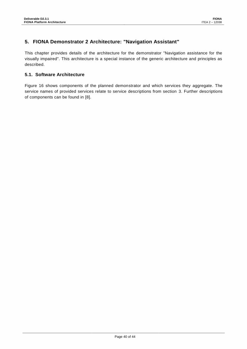
5. FIONA Demonstrator 2 Architecture: "Navigation Assistant"
This chapter provides details of the architecture for the demonstrator "Navigation assistance for the
visually impaired". This architecture is a special instance of the generic architecture and principles as
described.
5.1. Software Architecture
Figure 16 shows components of the planned demonstrator and which services they aggregate. The
service names of provided services relate to service descriptions from section 3. Further descriptions
of components can be found in [8].

Deliverable D2.3.1 FIONA Platform Architecture
FIONA ITEA 2 – 12038
Page 41 of 44
Figure 16: Software architecture of demonstrator 2
cm
p A
rch
ite
ctu
re
Lo
ca
liza
tio
n (
on
e o
f th
ese
co
mp
on
en
ts i
s u
sed
wit
hin
a d
em
on
stra
tor
run
;
co
mp
on
en
ts a
re a
lte
rna
tive
s)
Lo
ca
liza
tio
n (
on
e o
f th
ese
co
mp
on
en
ts i
s u
sed
wit
hin
a d
em
on
stra
tor
run
;
co
mp
on
en
ts a
re a
lte
rna
tive
s)
Ori
en
tati
on
(o
ne
of
the
se c
om
po
ne
nts
is
use
d w
ith
in a
de
mo
nst
rato
r ru
n;
co
mp
on
en
ts a
re a
lte
rna
tive
s)
Ori
en
tati
on
(o
ne
of
the
se c
om
po
ne
nts
is
use
d w
ith
in a
de
mo
nst
rato
r ru
n;
co
mp
on
en
ts a
re a
lte
rna
tive
s)
Le
ge
nd
Sm
art
Se
ns
orD
ata
Fu
sio
n (
ES
K)
ori
en
tati
on
Pro
vid
er
Co
mp
on
en
t
serv
ice
th
at
pro
vid
es
da
ta
serv
ice
th
at
req
ure
s d
ata
<<
Co
mm
un
icatio
n P
att
ern
>>
Co
mm
un
icatio
n O
bje
ct(
s)
... S
ee D
2.3
.1 f
or
deta
iled
desc
rip
tio
ns
of
serv
ices
<<
Pu
shTim
ed
>>
Co
mm
Orien
tatio
n
Sm
art
Vis
ua
lLo
ca
liza
tio
n (
Co
mla
nd
)
loca
tio
nP
rovid
er
Sm
art
iBe
ac
on
Lo
ca
liza
tio
n (
Bo
sc
h)
loca
tio
nP
rovid
er
ori
en
tati
on
Re
qu
est
or
Sm
art
Ha
pti
cB
elt
HM
I (B
os
ch
)
loca
tio
nR
eq
ue
sto
r
ob
sta
cle
Re
qu
est
or
de
stin
ati
on
Pro
vid
er
pa
thR
eq
ue
sto
r
- C
om
po
nen
t in
tern
ally
co
mm
un
icate
s w
ith
hap
tic b
elt a
nd
giv
es
navig
atio
n in
stru
ctio
ns
base
d o
n w
ayp
oin
ts: vib
ratio
ns
of
belt b
ase
d o
n
go
al an
d c
ur. lo
catio
n
- Th
e d
est
inatio
n r
oo
m f
or
blin
d d
em
on
stra
tor
is
giv
en
in
ad
van
ce.
Sm
art
Pa
thP
lan
nin
g (
Ha
ve
lsa
n)
pa
thP
rovid
er
loca
tio
nR
eq
ue
sto
r
rast
erM
ap
Re
qu
est
or
de
stin
ati
on
Re
qu
est
or
pro
file
Re
qu
est
or
<<
Pu
shTim
ed
>>
Co
mm
Lo
catio
n
<<
Pu
shTim
ed
>>
Co
mm
Lo
catio
n
<<
Pu
shN
ew
est
>>
Co
mm
Path
Co
mp
on
en
t re
qu
ires
a m
ap
fo
r p
ath
pla
nn
ing
fro
m w
hic
h it
is k
no
wn
wh
ich
grid
s are
access
ible
/in
access
ible
fo
r th
e u
ser.
Mo
tio
n c
om
man
d lo
gic
sh
ou
ld b
e e
mb
ed
ded
in
HM
I co
mp
on
en
t. T
his
co
mp
on
en
t
pro
vid
es
a lis
t o
f w
ayp
oin
ts.
Path
pla
nn
ing
do
es
no
t co
nsi
der
dyn
am
ic o
bst
acle
s (s
uch
as
bo
xes
on
th
e g
rou
nd
,
ch
airs
as
well
as
peo
ple
cro
ssin
g). I
t o
nly
co
nsi
ders
in
frast
ructu
re: w
alls
, d
oo
rs, st
airs,
etc
.. M
ap
is
no
t u
pd
ate
d d
urin
g r
un
tim
e, i.e
. o
bst
acle
s are
no
t ad
ded
to
map
an
d a
re
there
fore
no
t co
nsi
dere
d f
or
path
pla
nn
ing
.
Re-R
ou
tin
g:
No
way t
o in
itia
lize a
re-r
ou
tin
g v
ia a
serv
ice. R
e-r
ou
tin
g is
do
ne a
uto
matically
as
soo
n
as
there
is
a s
ho
rter/
bett
er
path
. Typ
ically
, th
is is
the c
ase
wh
en
th
e u
ser
takes
the
wro
ng
tu
rn.
=>
re-r
ou
tin
g if
path
is
blo
cked
by a
n o
bst
acle
is
no
t co
nsi
dere
d a
use
-case
in
path
pla
nn
ing
Path
will
be c
alc
ula
ted
as
a lis
t o
f g
rid
s. T
o t
he o
uts
ide, th
e g
rid
in
form
atio
n w
ill b
e
tran
sfo
rmed
to
co
ord
inate
s th
at
will
po
int
to t
he c
en
ter
of
the g
rid
s. T
his
will
use
th
e
rep
rese
nta
tio
n o
f "l
ocatio
n".
Sm
art
Po
se
Es
tim
ati
on
(C
ze
ch
Co
ns
ort
ium
)
ori
en
tati
on
Pro
vid
er
<<
Pu
shTim
ed
>>
Co
mm
Orien
tatio
n
Sm
art
Ob
sta
cle
De
tec
tio
n (
Bo
sc
h)
ob
sta
cle
Pro
vid
er
<<
Pu
shN
ew
est
>>
Co
mm
Dest
inatio
n
<<
Pu
shN
ew
est
>>
Co
mm
Ob
stacle
Sm
art
Ma
pP
rov
ide
r (H
av
els
an
)
rast
erM
ap
Pro
vid
er
<<
Qu
ery
>>
req
uest
: C
om
mR
ast
erM
ap
Req
uest
resp
on
se: C
om
mR
ast
erM
ap Sm
art
Pro
file
Pro
vid
er
(Ha
ve
lsa
n)
pro
file
Pro
vid
er
<<
Qu
ery
>>
req
uest
: C
om
mU
serP
rofile
Req
uest
resp
on
se: C
om
mU
serP
rofile
Rep
ly
Co
mp
on
en
t in
tern
ally
use
s a R
GB
D c
am
era
to
warn
of
ob
stacle
s.
Map
is
inte
rnally
lo
ad
ed
fro
m f
ile a
nd
pro
vid
ed
via
a s
erv
ice t
o o
ther
co
mp
on
en
ts.
Map
serv
ice p
rovid
es
grid
/pix
el m
ap
to
dis
pla
y t
he m
ap
on
HM
I.
Th
e u
ser
pro
file
is
read
fro
m f
ile.
Sto
ry: Th
e u
ser
pro
file
is
fixed
at
start
up
an
d n
ot
ch
an
ged
at
run
tim
e.
- W
ill p
rovid
e u
ncert
ain
ty/c
on
fid
en
ce.
- W
ill in
tern
ally
access
co
nfig
ura
tio
n f
ile w
ith
po
sitio
ns
an
d I
Ds
of
beaco
ns.
Th
is f
ile w
as
pre
vio
usl
y c
reate
d d
urin
g s
etu
p.
- W
ill in
tern
ally
use
USB
-do
ng
le t
o a
ccess
iB
eaco
ns.
- W
ill u
se in
pu
t o
f a c
olo
r im
ag
e.
- W
ill p
rovid
e u
ncert
ain
ty f
or
locatio
n a
nd
orien
tatio
n.
- In
tern
ally
lo
ad
s a 3
D m
od
el o
f th
e b
uild
ing
th
at
was
pre
vio
usl
y g
en
era
ted
(u
sin
g a
dep
th c
am
era
) b
y t
he
too
l/m
eth
od
develo
ped
by C
om
lan
d.
Inte
rnally
access
es
orien
tatio
n d
evic
e a
nd
pro
vid
es
orien
tatio
n
to t
he s
yst
em
.
- In
tern
ally
read
s se
rial d
ata
fro
m E
SK
sen
sor
fusi
on
develo
pm
en
t b
oard
an
d p
rovid
es
the o
rien
tatio
n t
o t
he
syst
em
.
- C
alib
ratio
n w
ill b
e d
on
e o
nce a
fter
inte
gra
tio
n in
to t
he
dem
on
stra
tor
is d
on
e.
- ESK
will
leave u
ncert
ain
ty u
nse
t in
th
e s
erv
ice.

Deliverable D2.3.1 FIONA Platform Architecture
FIONA ITEA 2 – 12038
Page 42 of 44
5.2. Hardware Architecture
The FIONA Demonstrator Device consists of a Laptop carried by the user, e.g. in a bag pack (Figure
17). The sensors are attached to the Laptop. The user interacts with the system using the haptic belt,
which is worn around the waist.
The illustrated hardware architecture is an exemplary instance for the FIONA demonstrator 1, see also
section 3.2.
Figure 17: Hardware Architecture of FIONA Demonstrator "Navigation Assistant"
class Hardware Architecture: Vis. Impaired Demonstrator
FIONA Dev ice
Alternatives
Building Infrastructure
«device»
Laptop
Ubuntu 12.04 Linux, 64bit,
Trusted Platform Module
support
«sensor»
Sensor Data Fusion Board
(ESK)
«sensor»
RGB Camera
«sensor»
Pose Estimation (Czech
Consortium)
«sensor»
Bluetooth Low Energy Dongle
«BLE beacon»
Beacon 1
«BLE Beacon»
Beacon n (...)
Vis. Impaired User
«actuator»
Haptic Belt
«RS232»
«USB»
«USB»
«BLE»
«BLE»
«USB»

Deliverable D2.3.1 FIONA Platform Architecture
FIONA ITEA 2 – 12038
Page 43 of 44
6. Index of Service Descriptions
GetIMU ......................................................................................................................................... 12
RFSignalRSSI .............................................................................................................................. 13
RFTOA ......................................................................................................................................... 13
RFAOA ......................................................................................................................................... 14
Satellite in View ............................................................................................................................ 14
GyroscopeInput ............................................................................................................................ 15
MagnetometerInput ....................................................................................................................... 15
ImageInput ................................................................................................................................... 16
ibeaconlistProvider ....................................................................................................................... 16
PointObjectDetected ..................................................................................................................... 17
VolumeObjectDetected ................................................................................................................. 17
obstacleProvider ........................................................................................................................... 18
orientationProvider........................................................................................................................ 18
locationProvider ............................................................................................................................ 19
rasterMapProvider ........................................................................................................................ 20
rasterMapInfoProvider .................................................................................................................. 21
CoordinateConversion .................................................................................................................. 22
destinationProvider ....................................................................................................................... 23
pathProvider ................................................................................................................................. 23
authenticationProvider .................................................................................................................. 24
LocalPath ..................................................................................................................................... 25
profileProvider .............................................................................................................................. 25
Points of Attention ........................................................................................................................ 27

Deliverable D2.3.1 FIONA Platform Architecture
FIONA ITEA 2 – 12038
Page 44 of 44
7. Bibliography
[1] (2015) Servicerobotik Ulm. [Online]. http://www.servicerobotik-ulm.de
[2] Christian Schlegel and Robert Wörz, "The software framework SMARTSOFT for implementing sensorimotor systems," in Proc. IEEE/RSJ Int. Conf. on Intelligent Robots and Systems (IROS), Kyongju, Korea, 1999, pp. 1610-1616.
[3] Christian Schlegel et al. (2015) SmartSoft Project Sourceforge. [Online]. http://sourceforge.net/projects/smart-robotics
[4] Christian Schlegel, Andreas Steck, and Alex Lotz, "Model-Driven Software Development in Robotics: Communication Patterns as Key for a Robotics Component Model," in Introduction to Modern Robotics.: iConcept Press, 2011.
[5] Christian Schlegel, Alex Lotz, and Andreas Steck, "SmartSoft - The State Management of a Component," Berichte des ZAFH Servicerobotik, Ulm, Technical Report ISSN 1868-3452, 2011.
[6] Hochschule Ulm. Servicerobotik Ulm Website: SmartSoft communication patterns. [Online]. http://www.servicerobotik-ulm.de/drupal/?q=node/39
[7] Alex Lotz, Andreas Steck, and Christian Schlegel, "Runtime Monitoring of Robotics Software Components: Increasing Robustness of Service Robotic Systems," in International Conference on Advanced Robotics (ICAR '11), Tallinn, Estonia, 2011.
[8] Christopher Brown, Mathias Bürger, and et al., "FIONA Deliverable D2.1.1: Use Cases and Requirements," FIONA Project, Project Deliverable 2015.
[9] Stampfer, Dennis et al., "D2.2.1: State of the Art on Service-Oriented Software Component Models," FIONA Project, Project Deliverable 2015.
[10] Christian Schlegel et al., "Model-Driven Software Systems Engineering in Robotics: Covering the Complete Life-Cycle of a Robot," in Workshop Roboter-Kontrollarchitekturen, co-located with Informatik 2013, Koblenz, 2013.
[11] Matthias Lutz, Dennis Stampfer, Alex Lotz, and Christian Schlegel, "Service Robot Control Architectures for Flexible and Robust Real-World Task Execution: Best Practices and Patterns," in Workshop Roboter-Kontrollarchitekturen, Informatik 2014, Stuttgart, 2014, ISBN 978-3-88579-626-8.
[12] Christian Schlegel et al., "Model-driven software systems engineering in robotics: Covering the complete life-cycle of a robot," it - Information Technology, vol. 57, no. 2, pp. 85–98, April 2015. [Online]. http://dx.doi.org/10.1515/itit-2014-1069
[13] (2014) RoboticsAtHsUlm Youtube Channel. [Online]. http://www.youtube.com/user/RoboticsAtHsUlm


