

Integrated ESIA GreeceSection 4 - Project Description

Page 2 of 88
Area Code
Comp. Code
System Code
Disc. Code
Doc.- Type
Ser. No.
Project Title: Trans Adriatic Pipeline – TAP GPL00-ASP-642-Y-TAE-0052Rev.: 01 Document Title: Integrated ESIA Greece
Section 4- Project Description
TABLE OF CONTENTS
4 PROJECT DESCRIPTION 6
4.1 TAP Project Overview 6 4.1.1 Purpose of the Project Description 6 4.1.2 TAP Project Scope and Location 7 4.1.3 TAP Project Rationale 8 4.1.4 TAP Project Schedule 8 4.1.5 Gas Properties 8 4.1.6 TAP System Throughput 9 4.1.7 TAP Design Philosophy 9 4.1.8 Applicable Codes and Standards 10 4.1.9 Contracting Goods and Services and Provision of Local Content 13
4.2 Main Project Components in Greece 14 4.2.1 Overview 14 4.2.2 Pipeline 15 4.2.3 Block Valve Stations (BVS) 17 4.2.4 Compressor Stations 17 4.2.4.1 EU Standards 19 4.2.4.2 World Bank Group (WBG) Standards 20
4.3 Project Construction 21 4.3.1 Introduction 21 4.3.2 Project Duration and Timing 22 4.3.3 Machinery, Equipment, Transportation and Traffic 23 4.3.4 Storage and Pipe Yards 26 4.3.4.1 Intermediate Storage Yard 26 4.3.4.2 Pipe Yards 26 4.3.5 Construction Camps 28 4.3.5.1 Pipeline Construction Camps 28 4.3.5.2 Compressor Station Construction Camps 30 4.3.5.3 Special Crossings and BVS Construction Camps 30 4.3.6 Access Transportation and Traffic 31 4.3.6.1 Overview 31 4.3.6.2 Access to Compressor Stations 31 4.3.6.3 Access to Pipeline 31 4.3.7 Services and Utilities 32
4.4 Construction and Pre-commissioning of the Pipeline 33 4.4.1 Land Acquisition 33 4.4.2 Pre-Construction Activities 33 4.4.3 Construction Methods 34 4.4.3.1 Overview 34 4.4.3.2 Team 1: Route Surveying and Preparation of Strip 42 4.4.3.3 Team 2: Trenching of the Pipeline 42 4.4.3.4 Team 3: Pipe Stringing, Bending and Welding 42 4.4.3.5 Team 4: Pipe Laying Installation and Backfilling 44 4.4.3.6 Team 5: Site Clean-up and Restoration 44 4.4.4 Pressure Testing during Construction (Hydrotesting) 45

Page 3 of 88 Area Code
Comp. Code
System Code
Disc. Code
Doc.- Type
Ser. No.
Project Title: Trans Adriatic Pipeline – TAP GPL00-ASP-642-Y-TAE-0052Rev.: 01 Document Title:
Integrated ESIA Greece Section 4- Project Description
4.4.4.1 Hydrotest Concept 45 4.4.4.2 Water Abstraction Sources and Discharge Points 46 4.4.4.3 Discharge/Disposal Options 47 4.4.5 Construction Methods at Crossings 47 4.4.5.1 Overview 47 4.4.5.2 Road and Railway Crossings 48 4.4.5.3 Watercourse Crossings 49 4.4.5.4 Crossing of pipelines and cables 56 4.4.5.5 Pipeline Protection and Pipeline Stabilisation against Landslide and
Instability 56 4.4.5.6 River Bed Laying 56 4.4.5.7 Construction in Elevated Areas 57 4.4.5.8 Construction in Areas with High Water Table 57
4.5 Construction of Block Valve Stations 58 4.5.1 Location 58 4.5.2 Layout and Configuration 58 4.5.3 Construction Duration and Timing 58 4.5.4 Construction Method 58 4.5.5 Construction Equipment 59
4.6 Construction of Compressor Station 59 4.6.1 Location 59 4.6.2 Layout and Configuration 59 4.6.3 Construction and Duration and Timing 60 4.6.4 Construction Method 60 4.6.5 Construction Equipment 61
4.7 Use of Resources and Environmental Interferences during Construction and Pre-Commissioning 61
4.7.1 Introduction 61 4.7.2 Temporary Land Take 61 4.7.3 Material and Fuel Usage 63 4.7.3.1 Aggregate Materials 63 4.7.3.2 Other Materials 64 4.7.3.3 Fuel Usage 64 4.7.4 Water Consumption 65 4.7.5 Air Emissions 65 4.7.6 Noise Emissions 65 4.7.7 Liquid and Solid Waste Generation, Handling and Disposal 66 4.7.7.1 Waste Management 66 4.7.7.2 Waste Types and Amounts 68
4.8 Operation Phase 71 4.8.1 Operating Philosophy 71 4.8.2 Operation Control System 71 4.8.3 Operational Pipeline Safety 72 4.8.3.1 Cathodic Protection Installation 72 4.8.3.2 Leak Detection System (LDS) 73 4.8.3.3 Marking of Pipeline 73 4.8.3.4 Block Valve Stations 74 4.8.3.5 Data Management 74 4.8.4 Pipeline Maintenance 74 4.8.5 Compressor Station 75

Page 4 of 88 Area Code
Comp. Code
System Code
Disc. Code
Doc.- Type
Ser. No.
Project Title: Trans Adriatic Pipeline – TAP GPL00-ASP-642-Y-TAE-0052Rev.: 01 Document Title:
Integrated ESIA Greece Section 4- Project Description
4.8.5.1 Monitoring Facilities 75 4.8.5.2 Fire Fighting System 75 4.8.5.3 Electrical Power Supply 75 4.8.5.4 Diesel and Gas 77 4.8.5.5 Air and Noise Emissions from Compressor Station 77 4.8.5.6 Drainage and Effluent Management 79 4.8.5.6.1 Rain Water 79 4.8.5.6.2 Sanitary Sewer (Waste Water) 80 4.8.5.7 Compressor Station Telecommunication System 82 4.8.6 Permanent Land Take 83 4.8.7 Operational Workforce 84 4.8.8 Pipeline Monitoring and Surveillance 84
4.9 Decommissioning Phase 85
4.10 Preliminary Identification of the Potential Environmental / Socioeconomic Interferences 86
List of Tables
Table 4-1 Summary of Installed Capacity at Compressor Stations 18 Table 4-2 Benchmarking of Compressor Stations against EBRD Standards 20 Table 4-3 Overall Duration of Construction of Project Components 23 Table 4-4 Location, Area and Capacity of the Main Pipe Yards 27 Table 4-5 Number of Employees, Land Use and Infrastructure of the Large Camps for Flat
Regions 29 Table 4-6 Sites Suitable for Camps 29 Table 4-7 Number of Employees, Land Use and Infrastructure of the Camp for Compressor
Station 30 Table 4-8 Number of Employees, Land Use and Infrastructure of the Camps for Special
Crossings 30 Table 4-9 Summary table of Required Road Construction Works (upgrade) 32 Table 4-10 Potential Location and Rate of Advance of Work Spreads 34 Table 4-11 Water Requirements for Hydro Test Sections 46 Table 4-12 Major River and Canal Crossing Points 50 Table 4-13 Type and Number of River Crossings 55 Table 4-14 Equipment Expected to Be Used for the Construction of BVSs 59 Table 4-15 Land Take of the Project During Construction 63 Table 4-16 Estimated Material Consumption during Construction 64 Table 4-17 Estimated Fuel Consumption during Construction 64 Table 4-18 Water Consumption 65 Table 4-19 Typical Noise Levels for Construction Equipment 66 Table 4-20 Typical Noise Levels for Pre-commissioning Equipment 66 Table 4-21 Categories of Waste Generated During Construction and Pre-commissioning 68 Table 4-22 Typical Wastes Generated during the Construction and Pre-commissioning of the
Pipeline 69 Table 4-23 Construction Waste Inventory 70 Table 4-24 Project Land Take during Operation 84 Table 4-25 Main Potential Interferences to occur during the Project Phases 87

Page 5 of 88 Area Code
Comp. Code
System Code
Disc. Code
Doc.- Type
Ser. No.
Project Title: Trans Adriatic Pipeline – TAP GPL00-ASP-642-Y-TAE-0052Rev.: 01 Document Title:
Integrated ESIA Greece Section 4- Project Description
List of Figures
Figure 4-1 Typical Pipeline Working Strip (Regular and Reduced) ....................................... 16 Figure 4-2 Example Photographs of Pipeline Construction Activities showing Location and
Arrangement of Work Teams within a Spread ...................................................... 25 Figure 4-3 Indicative Arrangement of Construction Equipment across Work Teams within the
Spreads ................................................................................................................. 36 Figure 4-4 Photographs of Pipeline Working Strip Preparation and during Construction ....... 37 Figure 4-5 Schematic Diagram Illustrating the Rolling Sequence of Work Teams within the
Spreads ................................................................................................................. 38 Figure 4-6 Indicative Construction Activities in Work Teams 1, 2, 3, 4 and 5 ........................ 39 Figure 4-7 Location of Work Spreads and Relative Position of Work Teams within Spreads
showing Indicative Rates of Advance .................................................................... 41
List of Boxes
Box 4-1: Main Pipeline Design Codes 10 Box 4-2: Other Applicable Directives, Standards, Codes, Guidelines and Design
Considerations 11 Box 4-3: Applicable Directives, Standards, Codes and Guidelines Relevant to
Environmental Protection 12 Box 4-4: Key Applicable Directives, Standards, Codes and Guidelines Relevant to Safety 12 Box 4-5: Measures included in Local Content Strategy 13 Box 4-6 WBG HSE Standards 21

Page 6 of 88 Area Code
Comp. Code
System Code
Disc. Code
Doc.- Type
Ser. No.
Project Title: Trans Adriatic Pipeline – TAP GPL00-ASP-642-Y-TAE-0052Rev.: 01 Document Title:
Integrated ESIA Greece Section 4- Project Description
4 PROJECT DESCRIPTION
4.1 TAP Project Overview
4.1.1 Purpose of the Project Description
This Section describes the different components involved in the construction, operation and
decommissioning phases of the elements of the TAP Project that crosses Greece. It also
provides an overview of Project construction and operation management. The description
provided reflects the level of design detail available at this stage of project development. It should
be noted that the ESIA considers the worst case in terms of potential environmental and
socioeconomic impact (i.e. the ESIA identifies the likely significant effects arising from the largest
possible footprint, including Compressor and Metering Stations, and the presence of all
necessary installations for the 20 bcm/year case). The Project Description is based on the
technical input and engineering design documents, provided by the Project’s proponent and
establishes a series of development parameters and principles, from which the ESIA practitioners
can form the “Basis of Assessment”. These parameters and principles enable the ESIA to strike a
balance between adequately identifying the likely significant effects of the Project, while at the
same time providing flexibility in design during project development and implementation.
In addition to the text, the Project Description is supported with a number of specific figures and
maps, which are presented under Annex 3 Project Description Maps and Figures.
The Project Description is structured as follows:
TAP Project Overview (Section 4.1);
Main Project components in Greece (Section 4.2);
Project Construction (Section 4.3);
Construction of the Pipeline (Section 4.4);
Construction of Block Valve Stations (Section 4.5);
Construction of Compressor Stations (Section 4.6);
Use of Resources and Environmental Interferences During Construction and Pre-
Commissioning (Section 4.7);
Operation Phase (Section 4.8);

Page 7 of 88
Area Code
Comp. Code
System Code
Disc. Code
Doc.- Type
Ser. No.
Project Title: Trans Adriatic Pipeline – TAP GPL00-ASP-642-Y-TAE-0052Rev.: 01 Document Title: Integrated ESIA Greece
Section 4- Project Description
Decommissioning Phase (Section 4.9)
Preliminary Identification of the Potential Environmental / Socioeconomic Interferences
(Section 4.10).
4.1.2 TAP Project Scope and Location
The Project is a proposed gas pipeline starting in Greece, crossing Albania and the Adriatic Sea
and coming ashore in southern Italy, allowing gas to flow directly from the Caspian basin into
Western and South Eastern European markets. Further detail is presented in Section 2 – Project
Justification and the route through Greece and Albania is shown in Annex 3.1 –Overview Map of
the TAP.
The Project Description presented in this Section corresponds to the Greek part of TAP which
stretches 543 km from Kipoi to Nea Mesimvria (north-west of Thessaloniki) and to the
Greek/Albanian border. The section Kipoi to Nea Mesimvria mainly follows an existing pipeline
route.
Separate permitting documents will be issued for the other sections of the TAP Project, namely
the ESIA for the Albania sector and the ESIA for the Italian sector.
The base case route of the Greek Section of TAP has been developed through an extensive
route refinement process.
The corridor for the Nea Mesimvria to the Greek/Albanian border has been selected following an
extensive and thorough alternative corridor selection and assessment process, performed by
TAP AG between 2009 and 2011 with the aim to select a technically feasible pipeline corridor
with the least negative environmental, socioeconomic and cultural heritage impacts. A detailed
route refinement process, within the 2 km corridor, has been completed for the base case route.
Local route optimisation will be undertaken during the detailed design (see Section 2).
The section from Kipoi to Nea Mesimvria is running in parallel to the existing Greek pipeline
network. The corridor has been selected following the existing high pressure Natural Gas
Pipeline of DESFA as much as possible. For the pipeline route located away from the existing
Greek pipeline network, a corridor of 2 km along a centreline has been defined.
The Greek section of the TAP will be equipped with two compressor stations.

Page 8 of 88
Area Code
Comp. Code
System Code
Disc. Code
Doc.- Type
Ser. No.
Project Title: Trans Adriatic Pipeline – TAP GPL00-ASP-642-Y-TAE-0052Rev.: 01 Document Title: Integrated ESIA Greece
Section 4- Project Description
For the 10 bcm case one compressor station in the broader area of Kipoi (GCS00) is foreseen of
approximately 30-45 MW (2 operating and 1 spare compressors of 15 MW, each).
For the 20 bcm case the compressor station GCS00 needs to be developed to 75-90 MW by
installation of three additional compressors (15 MW, each) with associated facilities (total
capacity 5 operating and 1 spare compressors, 15 MW each). Furthermore an additional
compressor station located in the vicinity of Serres (GCS01) with a compressor power of
approximately 100 – 125 MW (4 operating and 1 spare compressors of 25 MW, each) is foreseen
in the 20 bcm case. (such as filter, cooler, meter, etc.). The indicated MW-figures are related to
ISO class. The actual figures may deviate slightly.
4.1.3 TAP Project Rationale
The purpose of the TAP Project is to bring gas from new sources in the Caspian region to
Western and South Eastern Europe.
The TAP will contribute to the security and diversity of Europe’s energy supply by providing the
necessary infrastructure to transport gas through the pipeline system from the Shah Deniz II field
in Azerbaijan by the most direct route, via the pipeline system, to Southern Europe once
production begins in 2018.
4.1.4 TAP Project Schedule
Overall construction of the Greek section of the Project is anticipated to commence in mid-2015
and will take approximately 3.5 years, followed by commissioning during 2018.
4.1.5 Gas Properties
The pipeline will transport natural gas which is a naturally occurring gas mixture consisting
primarily of methane, typically with a range of 0–25% higher hydrocarbons and accompanying
substances (e.g. ethane, propane, butane, pentane, hexane, carbon dioxide, nitrogen, oxygen
and traces of sulphur). Before natural gas enters the TAP, it undergoes processing to remove
most of the impurities so that the natural gas can be used as a fuel. The TAP will therefore

Page 9 of 88 Area Code
Comp. Code
System Code
Disc. Code
Doc.- Type
Ser. No.
Project Title: Trans Adriatic Pipeline – TAP GPL00-ASP-642-Y-TAE-0052Rev.: 01 Document Title:
Integrated ESIA Greece Section 4- Project Description
transport natural gas, which is similar in composition to that provided for domestic and industrial
supply, for uses such as heating and power generation.
4.1.6 TAP System Throughput
Pipeline transportation capacity may be increased from an initial throughput of 10 bcm/year
(maximum about 1,350,000 standard cubic meters per hour; average about 1,190,000 standard
cubic meters per hour) to 20 bcm/year of natural gas.
4.1.7 TAP Design Philosophy
The TAP facilities (e.g. compressors and gas turbines) will be designed for a lifetime of 25 years.
The pipeline itself is designed for a technical life time of 50 years. The design philosophy is to
ensure that the gas transport system fulfils all safety requirements of the base National and
European Codes and Standards and that the impact to the natural and social environment is kept
to a minimum.
The pipeline and stations will be designed in accordance with requirements resulting from:
National and local regulations;
Safety of the people living close to the pipeline and of personnel working near the pipeline;
Protection of the environment;
Protection of property and facilities;
Geotechnical, corrosivity and hydrographical conditions;
Requirements for construction, operation and maintenance;
Third party activities.
The pipeline will have a design pressure of 95 barg (bars above atmospheric pressure), which
will be sufficient for the TAP capacity base case of 10 bcm/year as well as for the potential future
extension of the TAP System capacity to 20 bcm/year. The final design pressure will be defined
after finalisation of an iterative engineering process considering all relevant parameters.
However, it is anticipated that any changes will be very small deviations around the design

Page 10 of 88 Area Code
Comp. Code
System Code
Disc. Code
Doc.- Type
Ser. No.
Project Title: Trans Adriatic Pipeline – TAP GPL00-ASP-642-Y-TAE-0052Rev.: 01 Document Title:
Integrated ESIA Greece Section 4- Project Description
parameters described in this document and will not result in changes to the size and design of
the main project components in any meaningful way.
4.1.8 Applicable Codes and Standards
All Project facilities will be designed in accordance with the European Codes (EN) and National
Standards. The EU and National standards must be followed and other standards will be used to
supplement these where it is beneficial to do so.
For the TAP in Greece the main codes to be used are shown in Box 4-1.
Box 4-1: Main Pipeline Design Codes
No Δ3/A/οικ. 4303 ΠΕ 26010 5/3/2012 “Technical Regulation : Natural Gas supply systems — Pipelines for maximum operating pressure over 16 bar”
EN1594:2009 “Gas supply systems — Pipelines for maximum operating pressure over 16 bar — Functional requirements”
Examples of the other notable codes and standards to be applied include, but are not limited to,
the examples in Box 4-2.

Page 11 of 88 Area Code
Comp. Code
System Code
Disc. Code
Doc.- Type
Ser. No.
Project Title: Trans Adriatic Pipeline – TAP GPL00-ASP-642-Y-TAE-0052Rev.: 01 Document Title:
Integrated ESIA Greece Section 4- Project Description
Box 4-2: Other Applicable Directives, Standards, Codes, Guidelines and Design Considerations
Directive 2008/1/ EC of the European Parliament and the Council of 15 January. Design shall comply with BAT- principles (Best Available Technology);
Directive 1997/23/EC of the European Parliament and the Council of May 1997 regarding the design, manufacture, testing and conformity assessment of pressure equipment and assemblies of pressure equipment;
EN ISO 3183 Petroleum and natural gas industries - Steel pipe for pipeline transportation systems EN ISO 12327 Pressure Testing, Commissioning and decommissioning procedures for gas supply systems;
EN ISO 12732 Gas Supply Systems – Welding Steel Pipework, Functional Requirements;
EN ISO 14141 Valves for Natural Gas transportation in Pipelines;
EN ISO 12954 Cathodic Protection;
EN ISO 14780 Induction bends, fitting and Flanges;
EN ISO 21329 Mechanical Connectors;
EN 12186 Gas Supply Systems – Gas Pressure regulation stations for transmission and distribution –functional requirements;
EN 1776 Gas Supply Systems – Natural Gas Measuring Station – Functional Requirements;
DNV RP F105 Free Spanning Pipelines.
CEN/TS 15174 Guideline for Safety Management Systems for natural gas transmission pipelines.
TAP-HSE-PR-0010 Safety Design for Onshore Plants.
The entire pipeline system, including stations, will be designed in accordance with the applicable EU codes and standards, supplemented by local standards.
EN 12583 "Compressor stations".
Avoidance routing was the primary approach to selected constraints that are identified and mapped inside an investigated corridor. For areas where avoidance of the identified geo-hazards and selected constraints is not entirely possible, the relevant sections of infringement must be "earmarked" for closer investigation during the subsequent site investigations and other studies.
Parallel routes with other infrastructures, such as high voltage lines or roads, are preferred (so-called “infrastructure bundling”).
Crossings with other existing and /or planned infrastructural installations will be kept as short as possible.
A pipeline protection zone and safety zone will be implemented along the pipeline route. The pipeline will be installed in geologically stable areas with a gentle topography – side slopes and land slide areas must be avoided.
The pipeline will be designed according to Standard EN 1594 (Pipelines for Maximum Operating Pressure over 16 bar – Functional Requirement). The pipeline will have the following design framework:
a. Line pipe material: Steel Grade EN 10208-2 L485MB (or API equivalent X70) with 3-layer polyethylene-based coating;
b. Cathodic protection system;
c. The minimum cover depth for the pipeline is 1 m in regular sections and this can be increased in sensitive areas or because of special requirements.
The codes and standards relevant to noise and atmospheric emissions to be applied include, but
are not limited to, the examples in Box 4-3.

Page 12 of 88 Area Code
Comp. Code
System Code
Disc. Code
Doc.- Type
Ser. No.
Project Title: Trans Adriatic Pipeline – TAP GPL00-ASP-642-Y-TAE-0052Rev.: 01 Document Title:
Integrated ESIA Greece Section 4- Project Description
Box 4-3: Applicable Directives, Standards, Codes and Guidelines Relevant to Environmental Protection
Directive 2010/75/EU “Directive on Industrial Emissions”
2008/50/EC European Parliament Directive on ambient air quality;
2001/80/EC European Parliament Directive on the limitation of emissions of pollutants;
EU 2003-10/ EC of the European Parliament and the Council. The minimum health requirements regarding the exposure of workers to the risks arising from physical agents (noise);
2000/14/EC European Parliament Directive on Noise Directive);
2008/1/EC European Parliament Directive concerning integrated pollution prevention and control (the IPPC Directive). Design will comply with BAT- principles (Best Available Techniques);
2003/10/ EC European Parliament Directive on Minimum health requirements regarding the exposure of workers to risks arising from physical agents (noise);
IFC EHS Guidelines from the World Bank Group;
EN ISO 4871 Declaration and verification of noise emission values of machinery;
EN 21680 Noise levels for electrical rotating machines;
IEC 225 Specification for Octave-Band and Fractional-Octave-Band-Analog and Digital Filters;
IEC 651 Recommendations for Sound-Level Meters;
EEMUA Pub.140 Noise Procedure Specification (formally OCMA Spec. NWG1, Rev.2, 1980); and
ISO Standards Acoustics-Inc: Basic Standards, Methods of Noise Handbook 35 Measurement, Audiometry & Human exposure to noise
The key codes and standards relevant to safety to be applied include, but are not limited to, the
examples in Box 4-4.
Box 4-4: Key Applicable Directives, Standards, Codes and Guidelines Relevant to Safety
CEN/TS 15173 Frame of reference regarding Pipeline Integrity Management System;
CEN/TS 15174 Guideline for Safety Management Systems for natural gas transmission pipelines;
TAP-HSE-PR-0010 Safety Design for Onshore Plants.
DIN EN 16348 Gas infrastructure - Safety Management System (SMS) for gas transmission infrastructure and Pipeline Integrity Management System (PIMS) for gas transmission pipelines - Functional requirements.
A preliminary risk assessment1 of the pipeline route was performed with the aim of verifying the
pipeline safety. The preliminary assessment determined that the route was feasible with respect
to safety of the pipeline and the nearby population. In a few denser populated sections a potential
for route optimisation was identified in order to further reduce proximities to settlements.
Furthermore, the most populated sections identified are relatively short, enabling efficient
technical risk mitigation to be applied where needed or required. A detailed safety analysis will be
undertaken in the subsequent design phases and will also be part of the licensing processes.
1 ILF (2011) Preliminary Qualitative Risk Assessment Greece Doc. Ref. GPL00-ILF-100-S-TRS-0001 Rev.: 0C, dated 17-08-2011

Page 13 of 88 Area Code
Comp. Code
System Code
Disc. Code
Doc.- Type
Ser. No.
Project Title: Trans Adriatic Pipeline – TAP GPL00-ASP-642-Y-TAE-0052Rev.: 01 Document Title:
Integrated ESIA Greece Section 4- Project Description
4.1.9 Contracting Goods and Services and Provision of Local Content
TAP AG’s Policy on Corporate Social Responsibility (CSR) contains the commitment that “TAP
[AG] and its sub-contractors will recruit and source locally, work with local businesses and give
preference to both.” The Project plans to achieve this objective through the implementation of a
Local Content Strategy aimed at enhancing capacity of national level companies and increasing
local (Project Area) employment and procurement wherever possible. Specific measures
included under this strategy2 are given in Box 4-5.
Box 4-5: Measures included in Local Content Strategy
Enhancement of national supplier capacity:
In order to identify and quantify local content potential, identify potential employees, contractors and suppliers and obtain information on their capability to comply with TAP AG’s performance requirements, TAP AG will conduct a comprehensive demand- and supply-chain analysis;
TAP AG will implement a phased capacity building programme (sector by sector) that will enable local companies to achieve qualifications and potentially certification with the relevant standards and requirements well in advance of the tendering process;
TAP AG will engage with local government, industry and other organisations to determine opportunities for targeted training; and
Following selection of primary contractors, the Project will carry out training of contractors on the Project HSE and social policies prior to the start of construction.
Optimisation of national level contractor opportunities:
TAP AG will break down construction contracts into smaller components to increase the likelihood of granting individual pieces of work to Greek companies.
Optimisation of local employment opportunities:
TAP AG will agree an Employment Strategy with Primary Contractors that will include the expected level of local input for unskilled labour. Contractors will be required to source as much of the required unskilled labour as possible from within Greece with best efforts to recruit unskilled labour from the areas crossed by the pipeline. Agreed measures will be monitored and reported on.
Measures to spread employment opportunities evenly along the pipeline:
The Employment Strategy will define target locations for recruiting local unskilled labour by each of the four working spreads. This will help to smooth the distribution of employment opportunities along the pipeline route.
Integrity of recruitment process:
The Project will work with local authorities and employment organisations to ensure that all positions are advertised in a manner that is accessible to the settlements and communes crossed by the pipeline;
The Project will ensure that the recruitment process is fair and transparent, public and open to all regardless of ethnicity, religion or gender; and
TAP AG will stipulate that the Primary Contractor provides clear contracts prior to mobilisation stipulating working hours, pay, and other terms of employment.
Managing public expectations:
TAP AG will provide clear information on the number and limited timescales of employment opportunities. Information on the employment strategy will be disclosed at a commune centres and at all settlements within the 2 km corridor.
2 Implementation of these measures will be dependent on the final procurement strategy.

Page 14 of 88 Area Code
Comp. Code
System Code
Disc. Code
Doc.- Type
Ser. No.
Project Title: Trans Adriatic Pipeline – TAP GPL00-ASP-642-Y-TAE-0052Rev.: 01 Document Title:
Integrated ESIA Greece Section 4- Project Description
Sourcing local goods and services3:
As part of the tendering process, contractors will be required to develop a purchasing strategy that stipulates how national and local purchase of goods will be optimised. The purchasing strategy will be required to adhere to all TAP HSE policies and procedures. Agreed measures will be monitored and reported on;
Advance information on tendering opportunities will be provided to local businesses through trade and industry chambers and local business organisations along the pipeline route; and
Contractors will be required to show best efforts to fill unskilled service jobs in construction camps with local residents.
Source: TAP Policy on CSR (2011) (TAP-HSE-PO-0002), and TAP Local Content Strategy (2010) (TAP-HSE-ST-0007)
Due to World Trade Organisation (WTO) rules it is not possible to dictate the types and volumes
of local content for the provision of goods and services. TAP’s approach is to purchase each
service or good as close as possible to the location where the good or service is utilised, while
complying with established procurement guidelines.
TAP AG intends to adopt best practice and conduct a supply and demand analysis in a
transparent manner and in close collaboration with all stakeholders very early in the Project
development process. This will provide an opportunity to enhance local skills and capabilities in
advance of the tendering processes for goods and services, which will enable the local workforce
providers and suppliers to compete favourably.
4.2 Main Project Components in Greece
4.2.1 Overview
The pipeline system in Greece basically requires the following main installations:
An approximately 543 km long underground pipeline (48 inch) from the Greek/Turkish
border to Thessaloniki area, near Nea Mesimvria and the Greek/ Albanian border;
One or two Compressor Stations (including metering facilities for Compressor Station at
Kipoi);
22 BVS (Block Valve Stations - final number subject to further system studies), spaced at a
maximum of ~30 km along the pipeline; and
Associated facilities required during construction (access roads, construction camps, pipe
yards, etc.).
3 The approach for local sourcing will be dependent on the final procurement strategy and the way of contracting.

Page 15 of 88 Area Code
Comp. Code
System Code
Disc. Code
Doc.- Type
Ser. No.
Project Title: Trans Adriatic Pipeline – TAP GPL00-ASP-642-Y-TAE-0052Rev.: 01 Document Title:
Integrated ESIA Greece Section 4- Project Description
Figure 4-8 in Annex 3.5 Technical Drawings – Layouts and Flow Diagrams shows the system
flow diagram for the 10 bcm/year operational scenario.
4.2.2 Pipeline
The cross-country pipeline from the Greek/Turkish border to the Greek/Albanian border is
approximately 543 km in length and has a diameter of 48’’. The design pressure of the main
pipeline is 95 barg.
The minimum cover depth for the pipeline is 1 m in normal sections, but this can be increased if
necessary where additional protection is required. For example at road and railway crossings, the
minimum cover depth is increased to 1.2 m and 1.5 m respectively.
The location of the buried gas pipeline is shown in the Maps in Annex 3.2 Route Map of the TAP
Project in Greece and Annex 3.3 Route Map of the TAP Project in Greece in Detail. The laying of
fibre optic cables parallel to the pipeline will also be foreseen, as these are needed for
communication.
The width of the regular construction working strip for the TAP Project is 38 m, and can be
reduced to 28 m where physical constraints require. For construction in elevated areas the width
will potentially be further reduced to a minimum 18 m corridor.
A typical cross-section of a regular working strip and a reduced working strip are shown in the
following Figure 4-1.

Page 16 of 88 Area Code
Comp. Code
System Code
Disc. Code
Doc.- Type
Ser. No.
Project Title: Trans Adriatic Pipeline – TAP GPL00-ASP-642-Y-TAE-0052Rev.: 01 Document Title:
Integrated ESIA Greece Section 4- Project Description
Figure 4-1 Typical Pipeline Working Strip (Regular and Reduced)

Page 17 of 88
Area Code
Comp. Code
System Code
Disc. Code
Doc.- Type
Ser. No.
Project Title: Trans Adriatic Pipeline – TAP GPL00-ASP-642-Y-TAE-0052Rev.: 01 Document Title: Integrated ESIA Greece
Section 4- Project Description
4.2.3 Block Valve Stations (BVS)
At this stage of engineering 22 BVS will be installed along this section of the TAP in Greece, at
maximum intervals of approximately 30 km. Their locations are shown on the Maps in Annex 3.2
– Route Map of the TAP Project in Greece and Annex 3.3 – Route Map of the TAP Project -
Detail. Final design (e.g. number and distance between BVS) will be performed later and
depends on pipeline Risk Assessment, accessibility, national and international standards and an
agreed operation and maintenance concept.
The block valve stations are unmanned and contain a small cabinet with a fence around them to
prevent unauthorised access. Additional to the fenced area of approximately 12 x 33 m, a 3 m
wide vegetation strip will be planted and an access road installed to provide permanent access
during operation.
Figure 4-28 and Figure 4-29 in Annex 3.5 – Technical Drawings – Layouts and Flow Diagrams
provide illustrations of the typical block valve station layout and its associated fencing.
4.2.4 Compressor Stations
The pipeline’s initial transportation capacity is characterised by a throughput of 10 bcm/year but
might be increased to 20 bcm/year.
For the initial capacity of 10 bcm, one compressor station in the broader area of Kipoi (GCS00) is
foreseen of approximately 30-45 MW (2 operating and 1 spare compressors of 15 MW, each).
For the 20 bcm case the compressor station GCS00 needs to be developed to 75-90 MW by
installation of three additional compressors (15 MW, each) with associated facilities (total
capacity 5 operating and 1 spare compressors, 15 MW each). Furthermore one additional
compressor station located in the vicinity of Serres (GCS01) with a compressor power of
approximately 100 – 125 MW (4 operating and 1 spare compressors of 25 MW, each) is foreseen
in the 20 bcm case. (such as filter, cooler, meter, etc.). The indicated MW-figures are related to
ISO class. The actual figures may deviate slightly.
The compressor station is required to transport the gas by increasing the pressure. The
compressor station will mainly comprise of facilities for gas treatment (filter separators), metering,
compression and cooling. An access road will be installed to provide permanent access during
operation.

Page 18 of 88 Area Code
Comp. Code
System Code
Disc. Code
Doc.- Type
Ser. No.
Project Title: Trans Adriatic Pipeline – TAP GPL00-ASP-642-Y-TAE-0052Rev.: 01 Document Title:
Integrated ESIA Greece Section 4- Project Description
TAP has defined an area of 36 ha for the investigation of each of the CS sites, within which the
CS will be positioned during the final engineering phase. The compressor station facilities GCS00
and GCS01 require a surface of 16.7 ha and 16.3 ha correspondingly. This area will be fenced.
Within this surface, about 10 ha will be hosting installations, buildings or roads.
In each compressor station, a scraper station will be installed.
Additionally, there may be land use restrictions on the land surrounding the compressor station
triggered by risk protection requirements. Safety distances currently shown within the station
layout are based on engineer experience. They will be verified during the Risk Assessment
process and may be adjusted depending on the results of the assessments.
The power for the compressors is provided from gas turbines that are located at the compressor
station. The number and size of the gas turbines has been optimised to provide the appropriate
power requirements for the desired operational parameters of the pipeline. Table 4-1 provides a
summary of the installed gas turbine units at Compressor Stations for the 10 and 20 bcm/year
scenario including the number of redundant units on standby for backup. The fall back generators
are estimated to run at only very rare constellations, operation times a year a therefore estimated
< 300 h. Emergency power generators even less.
The fuel for the gas turbines is natural gas taken from the gas pipeline. Exhaust gas from each
turbine will be discharged to the atmosphere via one dedicated stack per gas turbine (each
approx. 30 m high). Further, a venting stack of approximately 70 m is envisaged through which
natural gas can be released in the case of unplanned overpressure in the system.
Table 4-1 Summary of Installed Capacity at Compressor Stations
Pipeline Capacity GCS00, GCS01)
10 bcm/year GCS00 ( Kipoi) 30-45 MW (2 operating and 1 spare of 15 MW each) , in the broader area of the existing DESFA compressor station at Kipoi
20 bcm/year GCS00 (Kipoi): approx. 75-90 MW (5 operating and 1 spare of 15 MW each)
GCS01 (Serres): approx. 100 - 125 MW (4 operating and 1 spare of 25 MW each), in the broader area south of Serres
Source: ENT 2012
Figure 4-30 (a) and (b) in Annex 3.5 – Technical Drawings – Layouts and Flow Diagrams shows
the layout of a typical compressor station and identifies the key components.4
4 Layouts are indicative only. Final layout will depend on chosen supplier of the units.

Page 19 of 88 Area Code
Comp. Code
System Code
Disc. Code
Doc.- Type
Ser. No.
Project Title: Trans Adriatic Pipeline – TAP GPL00-ASP-642-Y-TAE-0052Rev.: 01 Document Title:
Integrated ESIA Greece Section 4- Project Description
4.2.4.1 EU Standards
The compressor stations will be equipped with 15 MW ISO class gas turbines (each with a
thermal input of 45.45 MW). The GCS00 complex will fall under the EU Integrated Pollution
Prevention and Control (IPPC) Directive (2008/1/EC) and the IED Industrial Emissions Directive
(2010/75/EU)5 because the installation will have a total thermal input exceeding the 50 MW
threshold.
EBRD Standards:
The EBRD Performance Requirement on Pollution Prevention and Abatement (PR3) sets out the
requirements for the Project design. According to this, the EBRD requires compliance with
relevant EU environmental standards and national legislation. Where EU environmental
requirements do not exist, a project is expected to apply other good international practice such as
the World Bank Group Environmental Health and Safety (EHS) Guidelines.
PR3 – Paragraphs 10, 11, 17 and 19 provide general guidance on the expected plant design and
performance relevant to the compressor station. Table 4-2 summarises how the Project is
addressing these requirements.
5 The new EU Industrial Emissions Directive (IED) (2010/75/EU), which must be implemented by the member states into national legislation by January 2013, contains the provision that smaller sources of one operation should under certain conditions be treated as one installation. The IED will replace seven existing directives, including the IPPC and LCP Directives, and in some instances strengthen provisions.
Page 20 of 88 Area Code
Comp. Code
System Code
Disc. Code
Doc.- Type
Ser. No.
Project Title: Trans Adriatic Pipeline – TAP GPL00-ASP-642-Y-TAE-0052Rev.: 01 Document Title:
Integrated ESIA Greece Section 4- Project Description
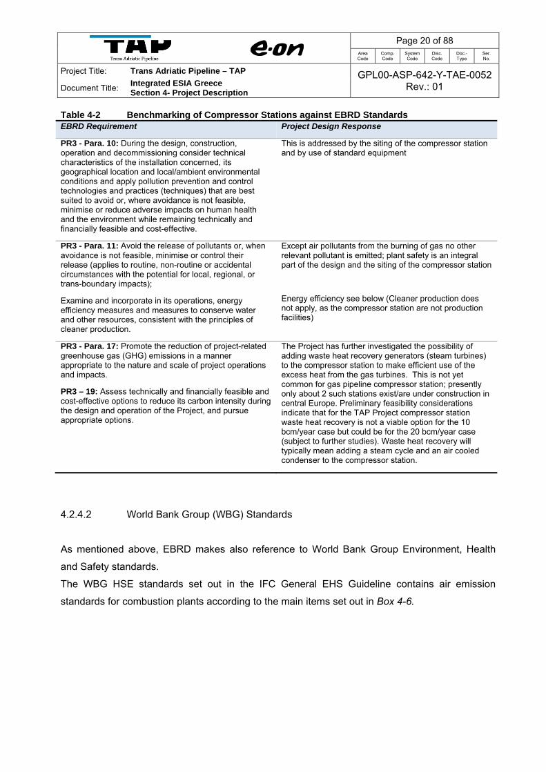
Table 4-2 Benchmarking of Compressor Stations against EBRD Standards EBRD Requirement Project Design Response
PR3 - Para. 10: During the design, construction, operation and decommissioning consider technical characteristics of the installation concerned, its geographical location and local/ambient environmental conditions and apply pollution prevention and control technologies and practices (techniques) that are best suited to avoid or, where avoidance is not feasible, minimise or reduce adverse impacts on human health and the environment while remaining technically and financially feasible and cost-effective.
This is addressed by the siting of the compressor station and by use of standard equipment
PR3 - Para. 11: Avoid the release of pollutants or, when avoidance is not feasible, minimise or control their release (applies to routine, non-routine or accidental circumstances with the potential for local, regional, or trans-boundary impacts);
Examine and incorporate in its operations, energy efficiency measures and measures to conserve water and other resources, consistent with the principles of cleaner production.
Except air pollutants from the burning of gas no other relevant pollutant is emitted; plant safety is an integral part of the design and the siting of the compressor station
Energy efficiency see below (Cleaner production does not apply, as the compressor station are not production facilities)
PR3 - Para. 17: Promote the reduction of project-related greenhouse gas (GHG) emissions in a manner appropriate to the nature and scale of project operations and impacts.
PR3 – 19: Assess technically and financially feasible and cost-effective options to reduce its carbon intensity during the design and operation of the Project, and pursue appropriate options.
The Project has further investigated the possibility of adding waste heat recovery generators (steam turbines) to the compressor station to make efficient use of the excess heat from the gas turbines. This is not yet common for gas pipeline compressor station; presently only about 2 such stations exist/are under construction in central Europe. Preliminary feasibility considerations indicate that for the TAP Project compressor station waste heat recovery is not a viable option for the 10 bcm/year case but could be for the 20 bcm/year case (subject to further studies). Waste heat recovery will typically mean adding a steam cycle and an air cooled condenser to the compressor station.
4.2.4.2 World Bank Group (WBG) Standards
As mentioned above, EBRD makes also reference to World Bank Group Environment, Health
and Safety standards.
The WBG HSE standards set out in the IFC General EHS Guideline contains air emission
standards for combustion plants according to the main items set out in Box 4-6.

Page 21 of 88 Area Code
Comp. Code
System Code
Disc. Code
Doc.- Type
Ser. No.
Project Title: Trans Adriatic Pipeline – TAP GPL00-ASP-642-Y-TAE-0052Rev.: 01 Document Title:
Integrated ESIA Greece Section 4- Project Description
Box 4-6 WBG HSE Standards
Where possible, facilities and projects should avoid, minimize, and control adverse impacts to human health, safety, and the environment from emissions to air. Where this is not possible, the generation and release of emissions of any type should be managed through a combination of:
o Energy use efficiency
o Process modification
o Selection of fuels or other materials, the processing of which may result in less polluting emissions
o Application of emissions control techniques
The selected prevention and control techniques may include one or more methods of treatment depending on:
o Regulatory requirements
o Significance of the source
o Location of the emitting facility relative to other sources
o Location of sensitive receptors
o Existing ambient air quality, and potential for degradation of the airshed from a proposed project
o Technical feasibility and cost effectiveness of the available options for prevention, control, and release of emissions
Source: IFC - General EHS Guidelines http://www.ifc.org/ifcext/sustainability.nsf/Content/EHSGuidelines
This in principle is aligned with the EBRD requirements. In addition, the General IFC HSE
Guidelines (Section 1.1 Air Emissions and Ambient Air Quality: Table 1.1.2) includes air emission
limits for gas turbines for nitrogen oxides (NOX) of 50 mg/m³, with which the TAP compressor
station gas turbines comply.
4.3 Project Construction
4.3.1 Introduction
At the current stage of project development, a detailed construction concept is not yet available.
First, the exact equipment needs, sites, and physical characteristics of the work areas cannot be
known until the design has further progressed; and second, the successful bidders for
construction contracts will have some leeway to select the work methods and equipment that
they will use, based on their own preferences as well as price and availability at the time the
contract is let.
Some general principles and approaches that will guide the construction of the Project can be,
however, set out at this stage in order to limit the above uncertainties for the purpose of this
ESIA. These, together with descriptions of equipment that might typically be used in such

Page 22 of 88 Area Code
Comp. Code
System Code
Disc. Code
Doc.- Type
Ser. No.
Project Title: Trans Adriatic Pipeline – TAP GPL00-ASP-642-Y-TAE-0052Rev.: 01 Document Title:
Integrated ESIA Greece Section 4- Project Description
circumstances are sufficient to indicate the likely nature and extent of the main environmental
and social impacts associated with construction of the TAP. This enables the ESIA to indicate the
methods, procedures and codes of practice that contractors will be required to use in order to
avoid, reduce or compensate for such impacts. These measures will then be incorporated into
the bidding documents and the contractual conditions for construction.
The following sections describe elements of the construction of the TAP in general terms and the
way in which each element is likely to be addressed, focusing on those aspects of most
relevance to the ESIA. Special variations from this general background, which may be needed for
specific components of the scheme or at particular construction sites, are addressed in the
relevant sections of the Project Description.
4.3.2 Project Duration and Timing
The tentative date for start of construction is mid-2015. The final, specific construction schedule
will depend on various technical and contractual matters and will take into account environmental
and socio-economic factors, such as the times of sensitive bird nesting, as discussed in detail in
the later sections of the ESIA report. Should construction commence in 2015, commissioning of
the Project will then take place during 2018.
Construction of the Greek section of the Project is anticipated to commence mid-2015 and will
last for approximately 3.5 years. Commissioning of the Project will commence in 2018.
The following Table 4-3 provides a summary of the expected timescales for the construction of
the major project components. It should be highlighted that work will be sequential and the
duration of construction at a specific location will be much shorter than the overall durations
indicated below (see Figure 4-7).

Page 23 of 88 Area Code
Comp. Code
System Code
Disc. Code
Doc.- Type
Ser. No.
Project Title: Trans Adriatic Pipeline – TAP GPL00-ASP-642-Y-TAE-0052Rev.: 01 Document Title:
Integrated ESIA Greece Section 4- Project Description
Table 4-3 Overall Duration of Construction of Project Components
Project Component Duration of Construction
Approx. 543 km underground pipeline Approx. 36 months* including preparatory works (41 months, including detailed engineering and pipe laying)
Metering/Compressor Stations 24 months
Access roads 9 months
22 Block Valve Stations (included in the pipeline construction period)
Construction camps Approx. 4 weeks for setting up
Pipe Yards Approx. 2 weeks for setting up
Source: Adapted from GPL00-ILF-100-F-TRP-0003_0D---TAP-FEED-GR-PLN-REP-1575--APPENDIX 3 - Comparison of Logistic Concepts – Greece (12-06-2011)
4.3.3 Machinery, Equipment, Transportation and Traffic
Although of a very large scale, the TAP will be a conventional civil engineering project, and will
not require unusual or unfamiliar equipment or construction techniques. The major items of
construction equipment needed are bulldozers, heavy excavators, spoil removal trucks, large,
heavy lift cranes, standby generators, excavators, side booms/pipe layers, rock breakers, etc.
Figure 4-2 shows some examples of the typical construction equipment and activities.
There will be significant transportation for each spread along the pipeline route, i) of the labour
material and equipment, ii) of the steel pipelines, and of the excavation spoil, although this will be
stored close to the trench, ready for backfilling. In order to facilitate the movement of equipment
and the construction workforce, a number of road upgrades will be required. The locations of the
roads which require upgrading are shown on the maps in Annex 3.3 Route Map of TAP Project
Detail.
Large earth moving machinery and other special items of equipment will be required to prepare
the construction working strip, to excavate the trench and lay the pipeline. To follow is an
estimate of additional construction traffic (per day). These predictions are indicative only, but are
based on experience of other similar pipeline construction projects. This traffic will apply to each
appropriate construction spread of the construction working corridor that is being used.
Approx. 30 two-way light vehicle movements (60 movements) per day to transport workers
to site (from the appropriate camp to the construction work area - 15 movements in the
morning and 15 movements in the evening);
Approx. 5 truck movements per day to move construction equipment (there are fewer
movements for construction equipment as these will be transported along the construction

Page 24 of 88 Area Code
Comp. Code
System Code
Disc. Code
Doc.- Type
Ser. No.
Project Title: Trans Adriatic Pipeline – TAP GPL00-ASP-642-Y-TAE-0052Rev.: 01 Document Title:
Integrated ESIA Greece Section 4- Project Description
working corridor where possible;
Approx. 50 two-way truck movements (100 movements) per day to bring material to the
construction working corridor (pipes, sand for sand bedding, etc); and
Approx. 10 two-way truck movements (20 movements) per day to take material away from
construction working corridor (e.g. excavated rocks which cannot be backfilled, clearing
and grading (timber).
Further details of the equipment that could be used for construction of the main Project
components and photographs showing examples of some of these major items are shown in
Figure 4-2.
Construction traffic will utilise the existing local road network and the new and upgraded roads to
access points along the pipeline construction corridor. Traffic will then travel up and down the
construction strip. Construction materials such as pre-fabricated pipe joints will be stored at
established pipe storage yards which will be located as per agreement with the relevant land
owners and/or municipalities. Materials will then be transported on heavy goods vehicles from
these locations to the construction corridor. Each pipe will be around 12 to 18 m long and could
weigh between 7 and 12 tonnes. Materials for civil construction will be temporarily stored within
the construction corridor. A Traffic Management Plan will be developed in consultation with the
competent authorities and municipalities, and implemented throughout construction.

CHECK TRANS ADRIATIC PIPELINE
CLIENT:
DATE
REV
PROJECT:
ISSUE, SCOPE OF REVISION PREP APR
TITLE:
SCALE PROJECT DRAWING NO: SHEET OF
No scale Figure 4-4 24/83
BIA PIB KAK
Size:A4
Trans Adriatic Pipeline (TAP)
Integrated ESIA Greece
B
SPREAD 1
Team 5 - Clean Up and Restoration Team
Activities : The dozers and graders will spread the reinstated material above the pipeline and blend the material into the natural contours.
Team 5
Team 4
Team 3
Team 2
Team 1
Assumed rate of advance for the work team in Spread 1 is @ 300 m/day. The individual teams will move along the 41 km spread at a rate of approximately 5 km every 17 days (see Figure 4.8). Approximately 25 km will be under construction at any one time.
41 km
Example Photographs of Pipeline Construction Activities showing Location and Arrangement of Work Teams within a Spread (typical)
A
Team 1 - Route Surveying, Set Out Team, Top Soil Stripping and Grading
Activities : Surveyors will put out flags and stakes to mark the route. Bulldozers and graders will clear away topsoil and stockpile in the working width. The graders and bulldozers will then level the right of way for the trench digging team.
Team 3 - Pipe Stringing, Bending and Pipe Welding Team
Activities : Pipe transporters will simultaneously deliver a steady stream of pipe alongside the working width. Welding teams will join pipe sections alongside the trench before lowering into the trench [see Team 4 activities]. Larger sections will be welded together in the trench.
Team 2 - Trench Digging Team
Activities : Excavators will dig out 4 m wide trench for pipe. Trench will be dug to a depth of 2.2 m, allowing min 1 m burial depth from top of pipe. Bulldozers will then push excavated material to form windrows and level the bedding in the base of the trench.
Team 4 - Pipe Laying, Installation and Backfilling Team.
Activities : Side booms and cranes will lower large pipe sections and manoeuvre them into place. Pipe sections will be welded together in bottom of trench. Hydro test crews will carry out integrity tests using water abstracted from waterbodies. Bulldozers will then push excavated material to form windrows and level the bedding in the base of the trench. Small backhoes and conveyors will reinstate excavated material back into the trench. Handheld whacker plates will compact material under and around the pipe. Vibrating rollers will compact the material above the pipeline.
Photographs sourced from various E.ON, E.ON Ruhrgas, ENT and OGE projects. Compiled by ERM (2011)
01 20/03/2013 Issued for Information

Page 26 of 88 Area Code
Comp. Code
System Code
Disc. Code
Doc.- Type
Ser. No.
Project Title: Trans Adriatic Pipeline – TAP GPL00-ASP-642-Y-TAE-0052Rev.: 01 Document Title:
Integrated ESIA Greece Section 4- Project Description
4.3.4 Storage and Pipe Yards
All key material such as pipes, components of the compressor stations and special construction
equipment will be shipped to the port of Thessaloniki or Kavala or Alexandroupolis.
There will be an intermediate storage yard and 17 pipe yards along the route.
The Contractor will have the opportunity to optimize his working concept and operate additional
pipe yards if required. Section 4.3.5 gives further detail on the likely access routes to the
proposed pipe yards.
4.3.4.1 Intermediate Storage Yard
There will be an intermediate storage yard close to the main port at Thessaloniki or Kavala or
Alexandroupolis which will have sufficient pipe storage capacity to provide buffer storage in case
of construction delays6. TAP will upgrade existing roads for the execution of the project. The main
storage yard is used for storage only; there will be no bending, coating or cutting of pipe at this
location. The option of locating large storage yards in the port itself has been discounted due to a
lack of available space, safety concerns related to stacking, and the associated higher costs that
will be incurred for storage in the Port. Pipes will be distributed from the intermediate storage
yard to the 17 pipe yards distributed along the route at the locations described in Table 4-4. The
locations of the pipe yards are shown on the series of maps in Annex 3.3 – Route Map of TAP
Project Detail
4.3.4.2 Pipe Yards
The locations of pipe yards for the intermediate storage of pipes have been selected close to
main roads near the pipeline track to provide easy access for long trucks. All methods of storing
pipes will be designed to prevent any damage on line pipe and/or any coating material at any
stage. Some photos of pipe unloading and stacking activities at a pipe yard are shown on Figure
4-10 in Annex 3.6 – Technical Drawings – Working Strip, Construction Methods and Crossings.
Table 4-4 shows the location and the approximate capacity of the pipe yards.
6 GPL00-ILF-100-F-TRP-0003_00---TAP-FEED-GR-PLN-REP-1575--APPENDIX 3 - Comparison of Logistic Concepts – Greece (05-04-2012)

Page 27 of 88 Area Code
Comp. Code
System Code
Disc. Code
Doc.- Type
Ser. No.
Project Title: Trans Adriatic Pipeline – TAP GPL00-ASP-642-Y-TAE-0052Rev.: 01 Document Title:
Integrated ESIA Greece Section 4- Project Description
Table 4-4 Location, Area and Capacity of the Main Pipe Yards
Yard Location Supply Section length
Pipe Yard Area Pipe Yard Capacity
1 Kavissos 30 km 30,000 m² 2,100 pipes
2 Alexandroupolis port 20 km 20,000 m² 1,400 pipes
3 Arsakeio 39 km 39,000m² 2,800 pipes
4 Mesochori 24 km 24,000m² 1,500 pipes
5 Vafeika 27 km 27,000m² 1,700 pipes
6 Kavala port 54 km 60,000m² 4,400 pipes
7 Agios Christoforos 45 km 45,000m² 3,200 pipes
8 Gazoros 32 km 32,000m² 2,300 pipes
9 Ano Kamila 23 km 23,000m² 1,500 pipes
10 Lachanas 16.5 km 16,000m² 1,400 pipes
11 Krithia 33.5 km 34,000m² 2,400 pipes
12 Gefyra 40 km 40,000m² 2,700 pipes
13 Agios Loukas 40 km 40,000m² 2,600 pipes
14 Pirgi 40 km 40,000m² 3,000 pipes
15 Galateia 30 km 28,000m² 2,100 pipes
16 Korisos 23 km 24,000m² 1,700 pipes
17 Mesopotamia 26 km 27,000m² 1,900 pipes
Source: GPL00-ΕΝΤ-100-F-TLX-0005_0A – Greece Camps and Pipe Yards (2013)
Delivery of the pipes to the pipe yards will be in accordance with the construction time schedule.
The concept will be optimized in order to avoid long storage times or supply shortfalls on the
other hand. Transport of pipeline sections will be limited to daylight hours, as much as
practicable.
The pipe yards will feature enough capacity to serve as a buffer in case of construction delays.
During storage pipes will be protected against corrosion and other degradation. Measures will be
taken to prevent rolling and ensure stability of the pipe stacks. Regular pipes of 48” diameter may
be stacked in three layers, concrete coated pipes (e.g. for river crossings) may be stacked in two
layers maximum.
All pipe yards will be fenced, lighted and guarded. All installations are of temporary character and
will be removed completely (including foundations) after the construction period. The entire area
will be vegetated after demobilisation of infrastructure.

Page 28 of 88 Area Code
Comp. Code
System Code
Disc. Code
Doc.- Type
Ser. No.
Project Title: Trans Adriatic Pipeline – TAP GPL00-ASP-642-Y-TAE-0052Rev.: 01 Document Title:
Integrated ESIA Greece Section 4- Project Description
4.3.5 Construction Camps
There will be 8 main construction camps along the route. The Contractor will have the opportunity
to optimize his working concept and operate additional camps if required.
4.3.5.1 Pipeline Construction Camps
Camps will be located along the pipeline route at more or less regular distances, so that long
transport time for staff to the work place can be avoided. If possible, camps will be located close
to main roads with good connection to larger cities, allowing easy transport of personnel, food,
utilities etc. to the camp. Communities will be consulted to identify the best location for the
camps.
The locations depend on the forecasted work speed and directions. The Primary Contractor will
make its own arrangements for the housing and welfare of its employees by the erection, fitting
up and maintenance of temporary quarters and camp accommodation together with all services
at the places of work. The camps will be ‘open’ rather than ‘closed’ camps, but worker off-time
will be carefully managed. Construction camps will be developed for each part of the Project
before construction of pipeline and associated facilities begins. There may, however, be a
requirement for some small-scale and temporary accommodation in towns outside of the camps
during the pre-construction phase, while camps and roads are under construction.
The main camps will not be combined with major pipe yards and bending areas. Mass transport
of pipes and other material produce a large quantity of dust and noise; therefore, these areas
should be separated from accommodations and offices. The same concept applies for the
protection of residential areas. Major pipe yards and bending areas will be located away from
these areas as much as practical.
Temporary, self-contained construction camps will be set up and operated during construction. A
typical layout of a camp and examples of construction camps are shown on Figure 4-11 in Annex
3.6 – Technical Drawings – Working Strip, Construction Methods and Crossings. They will have
their own water and electrical supply as well as facilities for wastewater and garbage treatment.
Camp staff will provide housekeeping, meal services and medical services. Fresh water will be
provided from existing water supplies if available or alternatively from springs in the camp’s
surroundings. All wastewater will be treated according to national requirements prior to
dewatering in a river or leaching.

Page 29 of 88 Area Code
Comp. Code
System Code
Disc. Code
Doc.- Type
Ser. No.
Project Title: Trans Adriatic Pipeline – TAP GPL00-ASP-642-Y-TAE-0052Rev.: 01 Document Title:
Integrated ESIA Greece Section 4- Project Description
Topsoil will be removed and stored during the occupation of land. The surface of all traffic areas
will be temporarily covered at least with gravel. All camps will be fenced, lighted and guarded. All
installations are of temporary character and will be removed completely (including foundations)
after the construction period. The entire area will be vegetated after demobilisation of
infrastructure.
As the terrain in Greece is predominantly non-mountainous only one type of pipeline construction
camp is defined.
Table 4-5 Number of Employees, Land Use and Infrastructure of the Large Camps for Flat Regions
Large camps for flat regions
Number of employees Approx. 150 - 200 persons
Land use Approx. 50,000 m2 (200 x 250 m), 1 year
Infrastructure Accommodations, canteen, offices, workshops, storerooms, fuelling station, stock yards, parking areas, utilities, wastewater treatment
Source: GPL00-ΕΝΤ-100-F-TRP-0003_0Β – Logistic Study Greece East (01-02-2013)and GPL00-ILF-100-F-TRP-0003_00---TAP-FEED-GR-PLN-REP-1575--APPENDIX 3 - Comparison of Logistic Concepts – Greece (05-04-2012)
The sites proposed as suitable for camps are described in Table 4-6 along with their approximate
capacities.
Table 4-6 Sites Suitable for Camps
Camp Location Relevant Section Area approx. Staff approx.
1 Amfitriti-Alexandroupolis 0-65 km 50,000 m2 150-200
2 Komotini - Itea 65-140 km 50,000 m2 150-200
3 Chalkero 140-224 km 50,000 m2 150-200
4 Toumpa 224-294 km 50,000 m2 150-200
5 Krithia 294-359 km 50,000 m2 150-200
6 Paralimni 359-424 km 50,000 m2 150-200
7 Maniaki 424-490 km 50,000 m2 150-200
8 Ampelokipi 490-543 km 50,000 m2 150-200
Source: GPL00-ΕΝΤ-100-F-TLX-0005_Rev.:0A – Greece Camps and Pipe Yards (17-04-2013)

Page 30 of 88 Area Code
Comp. Code
System Code
Disc. Code
Doc.- Type
Ser. No.
Project Title: Trans Adriatic Pipeline – TAP GPL00-ASP-642-Y-TAE-0052Rev.: 01 Document Title:
Integrated ESIA Greece Section 4- Project Description
4.3.5.2 Compressor Station Construction Camps
The compressor stations will be built by a separate contractor, hence they will install their own
camp independent from that of the pipe laying contractor. Table 4-7 provides details of the
potential arrangements at the construction camps for the compressor station.
Table 4-7 Number of Employees, Land Use and Infrastructure of the Camp for Compressor Station
Camp for Compressor Station
Number of employees Approx. 600 persons
Land use Approx. 10,000 m2 (100 x 100 m) plus the area for the Compressor Station, approx.
2 years
Infrastructure Accommodations, canteen, offices, workshops, storerooms, stock yards, parking
areas, utilities, wastewater treatment
Source: GPL00-ΕΝΤ-100-F-TRP-0003_0Β – Logistic Study Greece East (01-02-2013)
4.3.5.3 Special Crossings and BVS Construction Camps
At special points (e.g. larger river crossings and BVSs) temporary small camps for construction
works will be installed. If possible the teams will not stay in these small camps overnight but be
based in nearby hotels or main camps.
Table 4-8 Number of Employees, Land Use and Infrastructure of the Camps for Special
Crossings
Camps for special points
Number of employees Approx. 10 - 20 persons
Land use Approx. 2,500 m2 (50 x 50 m), few weeks/months
Infrastructure Office container, leisure room, parking area, specific installations for construction
works (e.g. drilling rig)
Source: GPL00-ΕΝΤ-100-F-TRP-0003_0Β – Logistic Study Greece East (01-02-2013) and GPL00-ILF-100-F-TRP-0003_00---TAP-FEED-GR-PLN-REP-1575--APPENDIX 3 - Comparison of Logistic Concepts – Greece (05-04-2012)
All construction camps will be fenced, lighted and guarded. All the construction camps are of
temporary character and will be removed completely (including foundations) after the
construction period. The entire area will be vegetated after demobilisation of infrastructure.

Page 31 of 88 Area Code
Comp. Code
System Code
Disc. Code
Doc.- Type
Ser. No.
Project Title: Trans Adriatic Pipeline – TAP GPL00-ASP-642-Y-TAE-0052Rev.: 01 Document Title:
Integrated ESIA Greece Section 4- Project Description
4.3.6 Access Transportation and Traffic
4.3.6.1 Overview
The pipeline will be accessible via existing roads and few new roads (e.g. for access to HDD
sites) which would be established temporarily for construction. Along the pipeline route probably,
some existing road, track or trails sections will be upgraded for construction in order to allow the
passage of vehicles and retained for operational demands. All new roads follow mainly existing
tracks and trails which will be upgraded in order to allow the passage of vehicles. All upgraded
and new roads will remain open for public use during the construction period.
Permanent access is required to the compressor station for construction works as well as for
operation and maintenance. The heaviest transport units will be the Turbo Compressors with a
total weight of 40-100 tons.
For the above mentioned cases, a Technical Environmental Study (TES) will be elaborated
according to Law 4014/2011 art. 7 par.2 and art. 11 par. 11 and MD 167563/2013. Also, a TES
will be elaborated for any additional facilities that are not included in this ESIA and might be
required depending on the final design of the construction of the pipeline.
Table 4-9 summarises the road works required to provide access for construction. Maps in
Annex 3.3 show the locations of the access routes and the existing roads that require upgrade.
4.3.6.2 Access to Compressor Stations
The transport routes for the Compressor Stations are as follows:
For GCS00 (Kipoi) from Alexandroupolis port the transport route follows the Egnatia highway
(E90). For GCS01 (Serres) from Thessaloniki port the transport route follows the National Road
Thessaloniki-Serres (E-79).
4.3.6.3 Access to Pipeline
All pipes will be distributed to the yards along the pipeline route directly from the ports at
Thessaloniki, Kavala or Alexandroupoli. Transportation will be provided by regular trailers as all
yards are accessible via national roads.
Page 32 of 88 Area Code
Comp. Code
System Code
Disc. Code
Doc.- Type
Ser. No.
Project Title: Trans Adriatic Pipeline – TAP GPL00-ASP-642-Y-TAE-0052Rev.: 01 Document Title:
Integrated ESIA Greece Section 4- Project Description
From the pipe yards all further transports will be made by stringing trucks or in mountainous
regions with special transport vehicles. A network of access roads provides access to the pipeline
working strip in regular distances. Local access is mostly given by existing roads. The existing
road network is adequate for the needs of the project and mainly in good condition. In difficult
topography with lots of ascents and descents, long transports along the working strip shall be
avoided as the slopes are mostly too steep for any transport equipment. In steep sections
construction equipment will be secured by winches and pipe laying works will be carried out by
cableways.
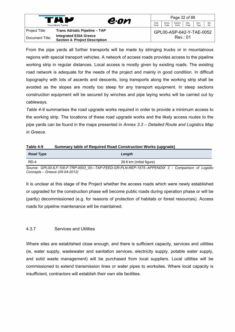
Table 4-9 summarises the road upgrade works required in order to provide a minimum access to
the working strip. The locations of these road upgrade works and the likely access routes to the
pipe yards can be found in the maps presented in Annex 3.3 – Detailed Route and Logistics Map
in Greece.
Table 4-9 Summary table of Required Road Construction Works (upgrade)
Road Type Length
RD-4 29.6 km (initial figure)
Source: GPL00-ILF-100-F-TRP-0003_00---TAP-FEED-GR-PLN-REP-1575--APPENDIX 3 - Comparison of Logistic Concepts – Greece (05-04-2012)
It is unclear at this stage of the Project whether the access roads which were newly established
or upgraded for the construction phase will become public roads during operation phase or will be
(partly) decommissioned (e.g. for reasons of protection of habitats or forest resources). Access
roads for pipeline maintenance will be maintained.
4.3.7 Services and Utilities
Where sites are established close enough, and there is sufficient capacity, services and utilities
(ie, water supply, wastewater and sanitation services, electricity supply, potable water supply,
and solid waste management) will be purchased from local suppliers. Local utilities will be
commissioned to extend transmission lines or water pipes to worksites. Where local capacity is
insufficient, contractors will establish their own site facilities.

Page 33 of 88 Area Code
Comp. Code
System Code
Disc. Code
Doc.- Type
Ser. No.
Project Title: Trans Adriatic Pipeline – TAP GPL00-ASP-642-Y-TAE-0052Rev.: 01 Document Title:
Integrated ESIA Greece Section 4- Project Description
4.4 Construction and Pre-commissioning of the Pipeline
4.4.1 Land Acquisition
Land will be acquired for permanent Project structures and to allow for operations, maintenance
and emergency access throughout the operational life of the Project. A major criterion of the
project design has been that, as far as is practical, permanent infrastructure should be sited on
unused land of no particular ecological or cultural value. Where this has not been possible, effort
has still been made to avoid land on which there are dwellings or public infrastructure, or which is
of high value as a habitat or for agriculture.
4.4.2 Pre-Construction Activities
Before starting any construction work, topographic and photographic records will be made of the
existing condition of the pipeline route and the access roads. These records will be used as the
standards against which the quality of the restoration work will be judged when construction work
is completed. The exact pipeline route will first be pegged out, while simultaneously staking out
the width of the working strip on both sides of the route. Obstructions such as walls, fences and
paths will be disturbed by the minimum amount necessary for safe working. Wall material will be
carefully dismantled and stored for reuse.
Records of buried facilities such as drains and irrigation pipe locations will be prepared and
verified with the landowner/user to prevent accidental damage during pipeline construction.
Existing third party services will be located, marked, and either safeguarded or diverted. Warning
posts will be erected for overhead cables, and temporary crossing points clearly identified. Other
pre-construction site activities will include:
Assessment of construction materials quantities;
Assessment of specific construction methods; and
Installation of construction site and worksites.

Page 34 of 88 Area Code
Comp. Code
System Code
Disc. Code
Doc.- Type
Ser. No.
Project Title: Trans Adriatic Pipeline – TAP GPL00-ASP-642-Y-TAE-0052Rev.: 01 Document Title:
Integrated ESIA Greece Section 4- Project Description
4.4.3 Construction Methods
4.4.3.1 Overview
The construction activities are described below, together with the techniques that will be used to
cross features such as roads and watercourses. The pipeline construction is a sequential process
and comprises a number of distinct operations, as shown in Figure 4-2 and Figure 4-3, which can
be broadly categorised under the following five headings:
Team 1: Route surveying, preparation of the working strip, top soil stripping and grading.
Team 2: Pipe stringing, bending and welding.
Team 3: Trench digging.
Team 4: Pipe laying, installation and backfilling.
Team 5: Site clean-up and restoration.
Final construction techniques will be determined during the detailed design.
The overall construction period will take 41 months, including detailed engineering and pipe
laying. The estimated laying rate ranges from 72 m/day in mountainous terrain up to 600 m/day in
flat terrain. There will be several working teams at the same time along the route. A detailed
working schedule will be developed in line with the tendering procedure.
The works to construct the 543 km pipeline will be broken down into manageable lengths called
“spreads”, and will utilise highly specialised and qualified work groups. The
Table 4-10 shows the Potential Location and Rate of Advance of Work Spreads for TAP Project
in Greece.
Table 4-10 Potential Location and Rate of Advance of Work Spreads
Work Spread Location KP Length (km)
Indicative Rate of Advance
Construction Period
Spread GE01 Kipoi – Pefka 0-42 42 300 m/day 2015-2017
Spread GE02 Pefka - Palagia 42-65 23 72 m/day 2015-2017
Spread GE03 Palagia - Amaranta/Komotoni
65-140 75 400 m/day 2015-2017
Spread GE04 Amaranta/Komotoni - Iasmos
140-177 37 350 m/day 2015-2017
Spread GE05 Iasmos - Neos Xerias 177-192 15 72 m/day 2015-2017

Page 35 of 88 Area Code
Comp. Code
System Code
Disc. Code
Doc.- Type
Ser. No.
Project Title: Trans Adriatic Pipeline – TAP GPL00-ASP-642-Y-TAE-0052Rev.: 01 Document Title:
Integrated ESIA Greece Section 4- Project Description
Work Spread Location KP Length (km)
Indicative Rate of Advance
Construction Period
Spread GE06 Neos Xerias - Amisiana 192-224 32 350 m/day 2015-2017
Spread GE07 Amisiana - Lefkothea 224-294 70 350 m/day 2015-2017
Spread GE08 Lefkothea - Serres 294-320 20 150 m/day 2015-2017
Spread GE09 Serres - Lachanas 320-359 45 300 m/day 2015-2017
Spread GE10 Lachanas - Melissochori 359-424 65 400 m/day 2015-2017
Spread GE11 Melissochori - Nea Mesimvria
424-446 22 72 m/day 2015-2017
Spread GW01 Nea Messimvria – Valtochori 446-484 38 350 m/day Within 2016
Spread GW02 Valtochori – Polla Nera 484-497 13 72 m/day Within 2016
Spread GW03 Polla Nera - Perdikkas 497-543 46 300 m/day Within 2016
Source: GPL00-ΕΝΤ-100-F-TRP-0003_0Β – Logistic Study Greece East (01-02-2013) and GPL00-ILF-100-F-TRP-0003_00---TAP-FEED-GR-PLN-REP-1575--APPENDIX 3 - Comparison of Logistic Concepts – Greece (05-04-2012)
Each of the spreads will consist of 5 work teams carrying out a number of different activities that
will operate along a rolling work front approximately 25 km in length Figure 4-3, Figure 4-6 and
Figure 4-7 show how the work teams will be broadly organised and the equipment that will be
used for each of the activities carried out within each of the spreads. Figure 4-4 shows example
photos of the typical equipment that will be used during construction. Figure 4-5 presents a
schematic diagram that illustrates the rolling sequence of operations that will be carried out by
each work team. Figure 4-7 illustrates the potential rate of progress by the work teams along the
pipeline route work spreads.

Page 36 of 88 Area Code
Comp. Code
System Code
Disc. Code
Doc.- Type
Ser. No.
Project Title: Trans Adriatic Pipeline – TAP GPL00-ASP-642-Y-TAE-0052 Rev.: 01 Document Title:
Integrated ESIA Greece Section 4- Project Description
Figure 4-3 Indicative Arrengement of Construction Equipment Across Work Teams within the Spreads
Equipment Number Equipment Number Equipment Number Equipment Number Equipment Number
Route surveying Trench digging Pipe bending Pipe Laying4-wheel land cruiser 2 Loaders (Cat) 3 Bending machine 1 Pipe-layer (Side-boom) 5 Loaders (Cat) 34-wheel pick-up 2 Excavators (Cat 320) 3 Bending machine stand-by 1 Padding machine 2 Excavators (Cat 320) 3GPS -station 2 Dozers (Cat D8) 2 4-wheel drive pick-up 1 Pay-welder (Cat D6) 1 Dozers (Cat D8) 1
Working corridor preparation
Conveyors 2 Pipe-layer (Side-boom 583) 1
Hydrotesting
Replacement of the Topsoil
Excavator 2 4-wheel pick-up 3 Pipe stringing Excavator 1 Excavator (Cat320) 4Shredder 1 Special trucks vacuum lift 4 Generator 1 Dozer (Cat D8) 3Timber-truck 2 Crane 40 t 2 Compressor 1 Grader 23 axle Truck 2 4-wheel drive pick-up 2 High-pressure pump 1 4-wheel truck 12 t 2Topsoil and grading 4-wheel drive truck 12 t 2 Pig 1 4-wheel land-cruiser 1Excavator (Cat320) 4 Pipe welding Dewatering and drying 4-wheel pick-up 2Dozer (Cat D8) 3 Main Crew Pump 14-wheel drive land-cruiser 1 Pay-welder (Cat D6) with 4 Generator / Compressor 1
4-wheel drive pick-up 2 4 welding machine - Pig magnetic 1Pipe-layer (Side-boom 583) 1 Foaming/Swabbing Pig 2Bus 35 Person 1Small CrewPay-welder (Cat D6) with 24 welding machine -Pipe-layer (Side-boom 583) 1Bus 20 Person 1NDT4-wheel drive -Truck + welding machine
1
4-wheel drive pick-up 2Joint coating4-wheel truck with crane 3Sand-blasting machine 3
Source: ENT (2013) 4-wheel pick-up 3
Backfill and Reinstatement of the Trench

Page 37 of 88 Area Code
Comp. Code
System Code
Disc. Code
Doc.- Type
Ser. No.
Project Title: Trans Adriatic Pipeline – TAP GPL00-ASP-642-Y-TAE-0052 Rev.: 01 Document Title:
Integrated ESIA Greece Section 4- Project Description
Figure 4-4 Photographs of Pipeline Working Strip Preparation and During Construction
Source (all pictures): ENT (2013)

Page 38 of 88 Area Code
Comp. Code
System Code
Disc. Code
Doc.- Type
Ser. No.
Project Title: Trans Adriatic Pipeline – TAP GPL00-ASP-642-Y-TAE-0052Rev.: 01 Document Title:
Integrated ESIA Greece Section 4- Project Description
Figure 4-5 Work Teams Rolling Sequence
Day 17 Day 34 Day 51 Day 68 Day 85 Day 102 Day 119 Day 136km4140 Team 1 Team 2 Team 3 Team 4 Team 53938373635 Team 1 Team 2 Team 3 Team 4 Team 5343332 Complete3130 Team 1 Team 2 Team 3 Team 4 Team 5292827 Complete Complete2625 Team 1 Team 2 Team 3 Team 4 Team 5242322 Complete Complete Complete2120 Team 2 Team 3 Team 4 Team 5191817 Complete Complete Complete Complete1615 Team 3 Team 4 Team 5141312 Complete Complete Complete Complete Complete1110 Team 4 Team 5987 Complete Complete Complete Complete Complete Complete65 Team 543 Complete Complete Complete Complete Complete Complete Complete21
Dir
ecti
on
of
Wo
rkfr
on
t M
ovem
en
t
DD DD DD
Approximate Progress of Work Spread 1 at 17 Day Intervals
Source: ENT (2013)
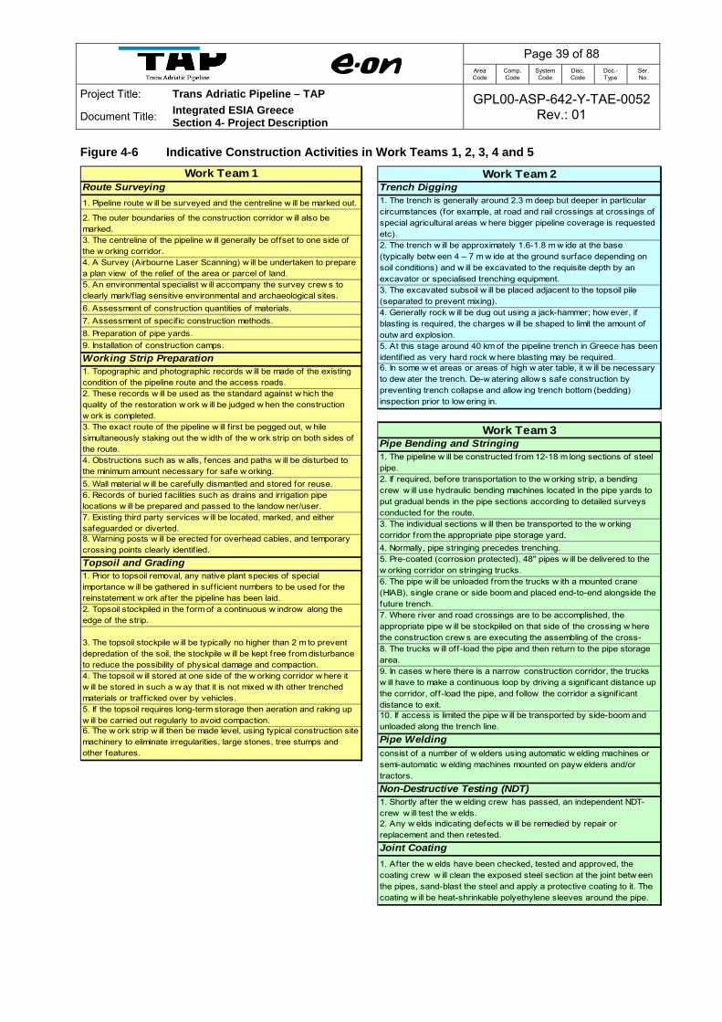
Page 39 of 88 Area Code
Comp. Code
System Code
Disc. Code
Doc.- Type
Ser. No.
Project Title: Trans Adriatic Pipeline – TAP GPL00-ASP-642-Y-TAE-0052Rev.: 01 Document Title:
Integrated ESIA Greece Section 4- Project Description
Figure 4-6 Indicative Construction Activities in Work Teams 1, 2, 3, 4 and 5
Work Team 1Route Surveying
1. Pipeline route w ill be surveyed and the centreline w ill be marked out.
2. The outer boundaries of the construction corridor w ill also be marked.3. The centreline of the pipeline w ill generally be offset to one side of the w orking corridor.4. A Survey (Airbourne Laser Scanning) w ill be undertaken to prepare a plan view of the relief of the area or parcel of land. 5. An environmental specialist w ill accompany the survey crew s to clearly mark/f lag sensitive environmental and archaeological sites.
6. Assessment of construction quantities of materials.
7. Assessment of specif ic construction methods.
8. Preparation of pipe yards.
9. Installation of construction camps.
Working Strip Preparation1. Topographic and photographic records w ill be made of the existing condition of the pipeline route and the access roads.2. These records w ill be used as the standard against w hich the quality of the restoration w ork w ill be judged w hen the construction w ork is completed.3. The exact route of the pipeline w ill f irst be pegged out, w hile simultaneously staking out the w idth of the w ork strip on both sides of the route.4. Obstructions such as w alls, fences and paths w ill be disturbed to the minimum amount necessary for safe w orking.
5. Wall material w ill be carefully dismantled and stored for reuse.6. Records of buried facilities such as drains and irrigation pipe locations w ill be prepared and passed to the landow ner/user.7. Existing third party services w ill be located, marked, and either safeguarded or diverted.8. Warning posts w ill be erected for overhead cables, and temporary crossing points clearly identif ied.
Topsoil and Grading1. Prior to topsoil removal, any native plant species of special importance w ill be gathered in suff icient numbers to be used for the reinstatement w ork after the pipeline has been laid.2. Topsoil stockpiled in the form of a continuous w indrow along the edge of the strip.
3. The topsoil stockpile w ill be typically no higher than 2 m to prevent depredation of the soil, the stockpile w ill be kept free from disturbance to reduce the possibility of physical damage and compaction. 4. The topsoil w ill stored at one side of the w orking corridor w here it w ill be stored in such a w ay that it is not mixed w ith other trenched materials or traff icked over by vehicles.5. If the topsoil requires long-term storage then aeration and raking up w ill be carried out regularly to avoid compaction.6. The w ork strip w ill then be made level, using typical construction site machinery to eliminate irregularities, large stones, tree stumps and other features.
Work Team 2Trench Digging1. The trench is generally around 2.3 m deep but deeper in particular circumstances (for example, at road and rail crossings at crossings of special agricultural areas w here bigger pipeline coverage is requested etc). 2. The trench w ill be approximately 1.6-1.8 m w ide at the base (typically betw een 4 – 7 m w ide at the ground surface depending on soil conditions) and w ill be excavated to the requisite depth by an excavator or specialised trenching equipment.3. The excavated subsoil w ill be placed adjacent to the topsoil pile (separated to prevent mixing). 4. Generally rock w ill be dug out using a jack-hammer; how ever, if blasting is required, the charges w ill be shaped to limit the amount of outw ard explosion.5. At this stage around 40 km of the pipeline trench in Greece has been identif ied as very hard rock w here blasting may be required. 6. In some w et areas or areas of high w ater table, it w ill be necessary to dew ater the trench. De-w atering allow s safe construction by preventing trench collapse and allow ing trench bottom (bedding) inspection prior to low ering in.
Work Team 3Pipe Bending and Stringing1. The pipeline w ill be constructed from 12-18 m long sections of steel pipe. 2. If required, before transportation to the w orking strip, a bending crew w ill use hydraulic bending machines located in the pipe yards to put gradual bends in the pipe sections according to detailed surveys conducted for the route.3. The individual sections w ill then be transported to the w orking corridor from the appropriate pipe storage yard.
4. Normally, pipe stringing precedes trenching.5. Pre-coated (corrosion protected), 48" pipes w ill be delivered to the w orking corridor on stringing trucks.6. The pipe w ill be unloaded from the trucks w ith a mounted crane (HIAB), single crane or side boom and placed end-to-end alongside the future trench. 7. Where river and road crossings are to be accomplished, the appropriate pipe w ill be stockpiled on that side of the crossing w here the construction crew s are executing the assembling of the cross-8. The trucks w ill off-load the pipe and then return to the pipe storage area.9. In cases w here there is a narrow construction corridor, the trucks w ill have to make a continuous loop by driving a signif icant distance up the corridor, off-load the pipe, and follow the corridor a signif icant distance to exit. 10. If access is limited the pipe w ill be transported by side-boom and unloaded along the trench line.
Pipe Weldingconsist of a number of w elders using automatic w elding machines or semi-automatic w elding machines mounted on payw elders and/or tractors.
Non-Destructive Testing (NDT)1. Shortly after the w elding crew has passed, an independent NDT- crew w ill test the w elds. 2. Any w elds indicating defects w ill be remedied by repair or replacement and then retested.
Joint Coating
1. After the w elds have been checked, tested and approved, the coating crew w ill clean the exposed steel section at the joint betw een the pipes, sand-blast the steel and apply a protective coating to it. The coating w ill be heat-shrinkable polyethylene sleeves around the pipe.
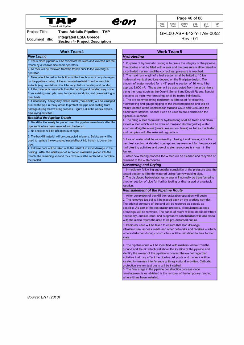
Page 40 of 88 Area Code
Comp. Code
System Code
Disc. Code
Doc.- Type
Ser. No.
Project Title: Trans Adriatic Pipeline – TAP GPL00-ASP-642-Y-TAE-0052Rev.: 01 Document Title:
Integrated ESIA Greece Section 4- Project Description
Source: ENT (2013)
Work Team 4Pipe Laying1. The w elded pipeline w ill be raised off the skids and low ered into the trench by a team of side boom operators. 2. All rock w ill be removed from the trench prior to the low ering-in operation.
3. Material w ill be laid in the bottom of the trench to avoid any damages on the pipeline coating. If the excavated material from the trench is suitable (e.g. sandstone) it w ill be recycled for bedding and padding. 4. If the material is unsuitable then the bedding and padding may come from: existing sand pits; new temporary sand pits; and gravel mining in river beds.5. If necessary, heavy duty plastic mesh (rock-shield) w ill be w rapped around the pipe in rocky areas to protect the pipe and coating from damage during the low ering process. Figure 4.3 in the Annex show s pipe laying activities.
Backfill of the Pipeline Trench
1. Backfill w ill normally be placed over the pipeline immediately after the pipe section has been low ered into the trench.
2. No sections w ill be left open over night.
3. The backfill material w ill be compacted in layers. Bulldozers w ill be used to replace the excavated material back into trench to cover the pipe. 4. Extreme care w ill be taken w ith the initial f ill to avoid damage to the coating. After the initial layer of screened material is placed into the trench, the remaining soil and rock mixture w ill be replaced to complete the backfill.
Work Team 5Hydrotesting
1. Purpose of hydrostatic testing is to prove the integrity of the pipeline. The pipeline shall be f illed w ith w ater and the pressure w ill be raised in a controlled manner until the correct test pressure is reached. 2. The maximum length of a test section shall be limited to 10 km horizontal, vertical sections depend on the f inal pipe design. The amount of w ater needed for a 48” pipeline section of 10 km w ill be approx. 6,000 m³. The w ater w ill be abstracted from the large rivers along the route such as the Osumi, Semani and Devolli Rivers. Special sections as main river crossings shall be tested individually.3. The pre-commissioning equipment w ill be used for cleaning, hydrotesting and gauge pigging of the installed pipeline and w ill be mainly located at the compressor stations CS02 and CS03 and the block valve stations, so that it can be used to pre-commission the pipeline in sections. 4. The f illing w ater required for hydrotesting shall be fresh and clean sw eet w ater w hich w ill be draw n from (and discharged to) w ater sources along the route (rivers, reservoirs, lakes) as far as it is tested and complies w ith the relevant regulations.
5. Use of w ater shall be minimized by f iltering it and reusing it for the next test section. A detailed concept and assessment for the proposed hydrotesting activities and use of w ater resources is show n in the Annex.
6. After dew atering process the w ater w ill be cleaned and recycled or returned to the w atercourse.
Dewatering and Drying1. Immediately follow ing successful completion of the pressure test, the tested section w ill be de-w atered using foam/sw abbing pigs. 2. The displaced hydrostatic test w ater w ill normally be transferred to another section of pipe for further testing or discharged at a suitable location.
Reinstatement of the Pipeline Route
1. After completion of backf ill the restoration operation w ill begin. 2. The removed top soil w ill be placed back on the w orking corridor. The original contours of the land w ill be restored as closely as possible. As part of the restoration process, all equipment access crossings w ill be removed. The banks of rivers w ill be stabilised w here necessary, and restored, and progressive rehabilitation w ill take place w ith the aim to return the area to its pre-disturbed nature.
3. Particular care w ill be taken to ensure that land drainage infrastructure, access roads and other netw orks and facilities – w hich w here disturbed during construction, w ill be reinstated to their former state.
4. The pipeline route w ill be identif ied w ith markers visible from the ground and the air w hich w ill show the location of the pipeline and identify the ow ner of the pipeline to contact the ow ner regarding activities that may affect the pipeline. All posts and markers w ill be located to minimise interference w ith agricultural activities. Cathodic protection system test posts w ill be installed. 5. The f inal stage in the pipeline construction process once reinstatement is established is the removal of the temporary fencing w here it has been installed.

Page 41 of 88 Area Code
Comp. Code
System Code
Disc. Code
Doc.- Type
Ser. No.
Project Title: Trans Adriatic Pipeline – TAP GPL00-ASP-642-Y-TAE-0052 Rev.: 01 Document Title:
Integrated ESIA Greece Section 4- Project Description
Figure 4-7 Location of Work Spreads (typical for Greece)
Note: WD – Working days

Page 42 of 88 Area Code
Comp. Code
System Code
Disc. Code
Doc.- Type
Ser. No.
Project Title: Trans Adriatic Pipeline – TAP GPL00-ASP-642-Y-TAE-0052Rev.: 01 Document Title:
Integrated ESIA Greece Section 4- Project Description
4.4.3.2 Team 1: Route Surveying and Preparation of Strip
Prior to construction, the pipeline route will be surveyed and the centreline will be marked out.
The outer boundaries of the construction corridor will also be marked. The centreline of the
pipeline will generally be offset to one side of the Working Strip. A survey (e.g. Airborne Laser
Scanning) will be undertaken to prepare a plan view of the relief of the area or parcel of land.
Environmental and archaeological specialists will accompany the survey crews to clearly
mark/flag sensitive environmental and archaeological sites.
Topsoil, which supports plant life and contains seed stock, will be removed from the Working
Strip by suitable earth moving equipment and stockpiled in the form of a continuous ridge along
the edge of the strip. The topsoil stockpile will be typically no higher than 2 m to prevent
degradation of the soil and will be kept free from disturbance to reduce the possibility of physical
damage and compaction.
The Working Strip will then be levelled, using typical construction site machinery, to eliminate
irregularities, large stones, tree stumps and other features.
The topsoil will be deposited on one side of the working corridor where it will be stored in such a
way that it is not mixed with other trenched materials or driven over by vehicles. If the topsoil
requires long-term storage, then aeration and raking up will be carried out regularly to avoid
compaction.
4.4.3.3 Team 2: Trenching of the Pipeline
The pipeline will be laid in a trench generally around 2 m deep. The trench (see Figure 4-14 in
Annex 3.4 – Technical Drawings - Construction Activities) will be approximately 1.6 m -1.8 m
wide at the base and will be excavated to the requisite depth by an excavator or specialised
trenching equipment (see Figure 4-15 in Annex 3.4 – Technical Drawings - Construction
Activities).
The excavated subsoil will be placed adjacent to the topsoil pile (separated to prevent mixing).
4.4.3.4 Team 3: Pipe Stringing, Bending and Welding
The pipeline will be constructed from approximately 12 to 18 m long sections of steel pipe. The
individual sections will be transported to the working strip from the pipe storage yard in the

Page 43 of 88 Area Code
Comp. Code
System Code
Disc. Code
Doc.- Type
Ser. No.
Project Title: Trans Adriatic Pipeline – TAP GPL00-ASP-642-Y-TAE-0052Rev.: 01 Document Title:
Integrated ESIA Greece Section 4- Project Description
Construction site. This activity involves transporting the pipes from the storage areas and
positioning them along the ROW. This operation will be carried out using side-booms and tracked
vehicles suitable for pipe transportation. The pipe will be unloaded with a mounted pipe-layer
crane, and side boom, and placed end-to-end alongside the future trench, taking special care not
to damage the pipe (see Figure 4-13 in Annex 3.4 – Technical Drawings - Construction
Activities).
Before the pipe is prepared for welding, a bending crew will bend the pipe in place where
necessary to match terrain contours (see Figure 4-13 in Annex 3.4 – Technical Drawings -
Construction Activities). The crew will use a hydraulic bending machine to put gradual bends in
the pipe. This equipment bends individual joints of pipe to the desired angle at locations where
there are significant changes in the natural ground contours, or where the pipeline route changes
direction. The bending will be limited to making many small bends along the length of a pipe
section until the desired summary bend angle has been reached.
The pipeline centreline will be surveyed with bending limitations in mind. Where the bend cannot
be made gradually enough to meet specific conditions, a prefabricated factory bend will be
inserted into the pipeline. These conditions will, however, be identified prior to construction.
The individual sections of pipe will be welded together to form the pipeline (see Figure 4-13 in
Annex 3.4 – Technical Drawings - Construction Activities). The weld will consist of several
passes (layers) depending on the pipe wall thickness. The pipes will be joined together using a
motor-driven welding machine by a continuous wire arc welding process (see Figure 4-13 in
Annex 3.4 – Technical Drawings - Construction Activities).
Pipes will be joined by connecting and welding several pipes so that a pipes string is formed and
placed on temporary supports along the edge of the trench. The weld will be tested by Non-
Destructive Testing (NDT) with radio graphic inspection, and any test results of questionable
quality will be retaken. Any welds indicating defects will be remedied by repair or replacement. In
this eventuality, the weld will be re-tested.
After the welds have been checked, tested and approved, the coating crew will clean the
exposed steel section at the joint between the pipes, sand-blast the steel, and apply a protective
coating to it. The coating will be heat-shrinkable polyethylene sleeves around the pipe. The
pipeline will be examined for coating damage after installation. The entire pipeline coating will be
electronically inspected, using Direct Current Voltage Gradient (DCVG) or any equivalent
technique, to assess the condition of coating to locate and repair any coating faults or voids.

Page 44 of 88
Area Code
Comp. Code
System Code
Disc. Code
Doc.- Type
Ser. No.
Project Title: Trans Adriatic Pipeline – TAP GPL00-ASP-642-Y-TAE-0052Rev.: 01 Document Title: Integrated ESIA Greece
Section 4- Project Description
4.4.3.5 Team 4: Pipe Laying Installation and Backfilling
The welded pipeline will be raised off the skids and lowered into the trench by a team of side
boom operators (see Figure 4-16 in Annex 3.4 – Technical Drawings - Construction Activities).
All rock will be removed from the trench prior to the lowering-in operation. It will be ensured that
in any case only stone-free material will be used for bedding the pipe sections. In areas of rocky
terrain, sand or sieved backfill material will be placed in the bottom of the trench and on both
sides of the pipe for protection purposes.
Before the pipe section is laid in the bottom of the trench, the insulation will be re-tested.
Following pipe laying the wooden skids or sand bags will be moved to the next trench section. All
other debris will be removed from the site and the trench will be inspected to ensure that no
debris has fallen in.
Backfill will normally be placed over the pipeline immediately after the pipe section has been
lowered into the trench. Backfill material in the direct vicinity of the pipe will be compacted in
layers. A backhoe loader will be used to replace the excavated material into the trench to cover
the pipe. Extreme care will be taken with the initial fill to avoid damage to the coating. After the
initial layer of screened material is placed into the trench, the remaining soil and rock mixture will
be replaced to complete the backfill (see Figure 4-16 in Annex 3.4 – Technical Drawings -
Construction Activities).
In order to avoid any damage to the pipeline coating and the bottom of the trench, the padding
material will consist of well graded, sandy material. Trenching material not used for backfill will be
removed and disposed of according to legal requirements.
4.4.3.6 Team 5: Site Clean-up and Restoration
After completion of backfill, the restoration operation will begin. The removed top soil will be
placed back on the working corridor. The original contours of the land will be restored as closely
as possible (see Figure 4-16 in Annex 3.4 – Technical Drawings - Construction Activities). As part
of the restoration process, all equipment access crossings will be removed.
Particular care will be taken to ensure that land drainage infrastructure, access roads, other
networks and facilities, and vegetation, which were disturbed/ moved during construction, will be
reinstated to their former state. Photographic records will be made of the route, where necessary,
before and after the works. If required, the final step will be the establishment of access barriers

Page 45 of 88 Area Code
Comp. Code
System Code
Disc. Code
Doc.- Type
Ser. No.
Project Title: Trans Adriatic Pipeline – TAP GPL00-ASP-642-Y-TAE-0052Rev.: 01 Document Title:
Integrated ESIA Greece Section 4- Project Description
to prevent trespassing on the ROW at appropriate points. All posts and markers will be located
to minimise interference with agricultural activities. Cathodic protection system test posts will be
installed.
The final stage in the pipeline construction process, once reinstatement is established, is the
removal of the temporary fencing where it has been applied.
4.4.4 Pressure Testing during Construction (Hydrotesting)
4.4.4.1 Hydrotest Concept
Hydrotesting (or hydrostatic testing) is the most common method for testing the integrity of the
pipeline and checking for any potential leaks (e.g. from faulty welds or cracked pipe) prior to
commissioning. The test involves placing water inside the pipeline at a certain pressure to check
that the pipeline is not damaged and will not leak during operation.
The first step in hydrotesting is the pipeline cleaning. This is carried out with a pipeline inspection
gauge or "PIG", which is a tool that is sent down a pipeline and propelled by the pressure of the
product in the pipeline itself e.g. the water used for hydro-testing or air used for pipe cleaning.
There are four main activities that will be performed by pigs during hydro-testing:
1. Cleaning of the inside of the pipeline, which is performed with a brush-type directional pig
that will be driven along the pipeline by air.
2. Testing of the pipe work and the welded joints using a "smart pig", which will measure pipe
thickness, corrosion and the integrity of welds along the pipeline.
3. Drying of the pipeline using foam-type swabbing pigs.
4. Gauge checking of the pipeline using a pig with a gauge plate attached. This pig is sent the
whole length of the pipeline to check for dents, imperfections and damages. The relevant
defect is then located and the damaged pipe section is repaired.
The pipeline is then filled with water, which is pressurised. The hydrotesting will be carried out in
approximately 70 sections, varying in length between 300 m and 23 km. Hydro testing activities
are expected to require a total of 5 to 6 months and will be finished before commissioning
activities.
The water used needs to be free of contaminants and not aggressive (pH between 5 and 8), and
no additives, corrosion inhibitors or chemicals are used. Pressurization is then carried out with a
high pressure pump.

Page 46 of 88 Area Code
Comp. Code
System Code
Disc. Code
Doc.- Type
Ser. No.
Project Title: Trans Adriatic Pipeline – TAP GPL00-ASP-642-Y-TAE-0052Rev.: 01 Document Title:
Integrated ESIA Greece Section 4- Project Description
After the pipeline has been filled and pressurised, and all the necessary parameters have been
measured, the pipeline is dewatered and dried.
4.4.4.2 Water Abstraction Sources and Discharge Points
Surface water sources with larger amounts of water flow have been considered for water
abstraction and discharge. Water reservoirs will not be used as a source for testing water.
The locations where water will be abstracted and discharged are limited. Table 4-11 shows the
potential water sources identified along the TAP pipeline route and the volumes required for
hydrotesting for each main section. The timing for the hydrostatic testing activities will consider
the seasonal changes of river flows and the reduced flows during the summer months.
The quantity of used water for hydrostatic testing varies from between 330 m³ for the shortest
testing sub-sections (300 m) and 25,220 m³ for the longest (23 km). The table below indicates
the required hydrotesting volumes. However the abstraction volumes would be far lower as the
hydrotest water will be reused as far as possible from one section to the other.
Table 4-11 Water Requirements for Hydro Test Sections
Hydrotest Spread Water Source Discharge Point Approx. Volume Required (m3)
GRE01 Evros River (KP 0) Evros River (KP 0) 51,880
GRE02 Filiouris River (KP 77.4) Filiouris River (KP 77.4) 40,200
GRE03 Xiropotamos (KP 113.0) Xiropotamos (KP 113.0) 33,820
GRE04 Xantis (Kosynthos) (KP 136.0) Xantis (Kosynthos) (KP 136.0) 31,170
GRE05 Nestos (KP 153.6) Nestos (KP 153.6) 25,230
GRE06 Angitis I (KP 223.7) Angitis I (KP 223.7) 55,620
GRE07 Strymonas (KP 290.3) Strymonas (KP 290.3) 62,230
GRE08 Parthenorema (KP 376) Parthenorema (KP 376) 28,970
GRW01 Parthenorrema (KP 382.3) Axios (KP 376.0) 15,420
GRW02 Parthenorrema (KP 382.3) and Potamos (KP 419.9)
Potamos (KP 419.9) and Ammorycheias (KP 469.3)
55,070
GRW03 Potamos (KP 419.9) Ammorycheias (KP 469.3) 52,870
GRW04 Ammorycheias (KP 469.3) Ammorycheias (KP 469.3) 33,040
GRW05 Aliakmonas (KP 524.6) Aliakmonas (KP 524.6) 43,200
Source: GPL00-ΕΝΤ-100-F-TRS-0001_00 – Hydrostatic Testing Concept (21-02-2013) and ILF (2012) GPL00-ILF-100-F-TRS-0001_00--Hydrostatic Testing Concept - Greece

Page 47 of 88 Area Code
Comp. Code
System Code
Disc. Code
Doc.- Type
Ser. No.
Project Title: Trans Adriatic Pipeline – TAP GPL00-ASP-642-Y-TAE-0052Rev.: 01 Document Title:
Integrated ESIA Greece Section 4- Project Description
The contractor for the hydrotest will obtain written approvals from the local authorities and the
landowner(s) where the source of water is located prior to the extraction of hydro test water.
Figure 4-17 in Annex 3.6 – Technical Drawings – Working Strip, Construction Methods and
Crossings shows the proposed water abstraction and discharge locations for hydrostatic testing.
4.4.4.3 Discharge/Disposal Options
Following successful testing, the used water will be discharged back into a receiving water body
after having passed a sedimentation pool, through which the water will flow very slowly. These
pools will be sized to provide a retention time of 5 minutes, which is considered enough time for
allowing the solid particles cleaned out of the pipe to settle and remain in the bottom of the pond.
The discharge rate after finalisation of hydro tests will follow the same rules as applicable for
abstraction. Hence the same water bodies will be taken into consideration for discharge.
Environmental effects are expected to be minimal or negligible when discharge rates are under
10% of the receiving river flow. Discharged water will be free of any chemicals.
The contractor for hydro testing will obtain written approvals from the local authorities and the
landowner(s) where the hydro test water will be discharged, water will not be returned to any
watercourse without permission of the appropriate local authorities.
4.4.5 Construction Methods at Crossings
4.4.5.1 Overview
The pipeline route crosses many areas requiring specialised construction approaches.
The pipeline route in Greece crosses one highway (4 crossings), fourteen major roads (22
crossings), 110 secondary roads, 1079 unclassified roads and tracks and one railroad line (11
crossings). In addition, it requires 25 river crossings, including 18 major rivers, also numerous
channel crossings, medium watercourses and smaller streams and creeks. Where necessary,
construction methods that avoid interferences or visible long term impacts will be used for
crossings in order to minimise impacts on traffic and the environment.
Crossings will be installed in parallel with or in front of the mainline working corridor. Separate
crews will install bored crossings for roads and highways along the pipeline corridor. These crews

Page 48 of 88 Area Code
Comp. Code
System Code
Disc. Code
Doc.- Type
Ser. No.
Project Title: Trans Adriatic Pipeline – TAP GPL00-ASP-642-Y-TAE-0052Rev.: 01 Document Title:
Integrated ESIA Greece Section 4- Project Description
will perform the excavation, welding, and installation of the crossing pipe. All pipeline crossings
will be tested to ensure that there are no leaks.
Increased burial depths at important crossings (roads, rivers, railways) and steep slopes will help
maintaining the safety and structural integrity of the pipeline.
The requirements and technical instructions of the competent authorities will be taken into
account in the detailed design and construction of crossings.
Crossing techniques can be divided into open cut (where the trench is dug directly across the
feature), and trenchless crossing methods which prevent surface disturbance. Trenchless
crossing methods include jack and bore, thrust-boring, auger boring, micro-tunnelling and
horizontal directional drilling (HDD). These methods are used where ground conditions permit,
and where disruption to others will be unacceptable or where there will be significant damage to
the environment by the use of open cut methods.
All rivers crossings are planned with the open-cut technique unless trenchless techniques are
required due to environmental, technical and engineering constraints.
4.4.5.2 Road and Railway Crossings
At locations where the pipeline crosses a road, the crossing will be accomplished by either the
open cut or jack and bore method. Jack and bore (also known as augur boring or horizontal
boring) will be the least disruptive method, but this technique cannot be used effectively in areas
where boulders or rock are present or for crossings longer than approximately 60 m. Figure 4-18
in Annex 3.6 – Technical Drawings – Working Strip, Construction Methods and Crossings
illustrates the jack and bore technique. Where jack and bore is not possible, the open cut method
will generally be used. It is anticipated that all highways will be crossed using the jack and bore
method to avoid disruption of the traffic. Figure 4-19 and 4-20 in Annex 3.6 – Technical Drawings
– Working Strip, Construction Methods and Crossings, show schematics of the road and highway
crossings.
Jack and bore will require the digging of a pit on one side of the road. The boring machine will be
lowered into the pit to begin boring, with the pipe inserted into the hole as it is being drilled.
The outside of the pipe will be coated with concrete or abrasion resistant material to protect the
pipe coating from being damaged as it is pushed through the bore hole. As each complete joint of
pipe is installed another joint of pipe welded to the first joint and boring will continue. This method
will continue until the boring machine and the pipe are received in a "capture" pit on the opposite

Page 49 of 88 Area Code
Comp. Code
System Code
Disc. Code
Doc.- Type
Ser. No.
Project Title: Trans Adriatic Pipeline – TAP GPL00-ASP-642-Y-TAE-0052Rev.: 01 Document Title:
Integrated ESIA Greece Section 4- Project Description
side of the crossing. The integrity of the pipe welds will then be tested to ensure that there are no
leaks.
Railways will be crossed generally by the jack and bore method. For railway and road crossings
where the relevant authority or road owner requests the installation of a casing pipe, the jack and
bore method described above will apply to this casing pipe (see Figure 4-21 and 4-22 in Annex
3.6 – Technical Drawings – Working Strip, Construction Methods and Crossings). Following this,
the pipe will be pulled into the casing pipe. Spacers will ensure the pipe is separated from the
casing pipe wall during the pulling-in operation. In addition, fluid cement such as bentonite will be
used to fill the space between the casing and pipe in order to prevent any contact between the
gas- and the casing pipe after hardening, thus ensuring proper cathodic protection of the pipe
during operation.
In addition to public highways, there will be crossings of farm access roads, and other drives and
tracks. The majority of these are un-surfaced and are likely to be crossed by the open cut method
of construction.
When the open cut method is used, traffic will be diverted around the crossing via detours or
temporary roads. To minimise the duration of traffic disruption, the pipe will be prepared prior to
commencement of roadway excavation. Once the pipeline has been installed, the trench will be
backfilled and compacted in layers in accordance with relevant agency specifications.
The roadway will then be resurfaced over the compacted trench. Final selection of crossing
methods will be coordinated with the appropriate road management authority.
4.4.5.3 Watercourse Crossings
The largest rivers that will be crossed are the tributaries of Evros, Apokrimno, Filiouris, Bosbos,
Aspropotamos, Xiropotamos, Xanthis, Nestos, Philippoi channel, Aggitis, Krousovitis, Strymonas,
Gallikos, Axios, Aliakmonas and Loudias. Additionally a number of smaller watercourses will also
be crossed by the Project route. It is estimated that a total of 25 river crossings will be required.
The open cut method is the preferred option for crossing watercourses as this is proven and safe
technology. The method differs slightly depending on the size of the crossing. Major rivers, i.e.
Evros, Filiouris, Xiropotamos, Nestos, Strymonas, Aggitis, Axios Vardarvasi, Grammatiko Creek
and Aliakmonas I, II & III can be crossed by Horizontal Directional Drilling (HDD), provided that
geotechnical conditions allow it (subject to further geotechnical investigations). HDD is a
technique that avoids impacts to the river itself (i.e. banks, riverbed, water quality) and loss of the
riparian vegetation. This is of particular importance at the Evros, Filiouris, Xiropotamos, Nestos,

Page 50 of 88 Area Code
Comp. Code
System Code
Disc. Code
Doc.- Type
Ser. No.
Project Title: Trans Adriatic Pipeline – TAP GPL00-ASP-642-Y-TAE-0052Rev.: 01 Document Title:
Integrated ESIA Greece Section 4- Project Description
Strymonas, Aggitis, Axios Vardarvasi, Grammatiko Creek and Aliakmonas I, II & III rivers where
the pipeline is crossing very important protected areas.
The proposed engineering measures will fulfil the following objectives:
Secure the technical integrity of the pipeline during operations.
Minimise the environmental impact of the crossing.
Provide a cost efficient solution.
Typical river crossing techniques are illustrated in Figure 4-23 and Figure 4-24 in Annex 3.6 –
Technical Drawings – Working Strip, Construction Methods and Crossings. Table 4-12 provides a
summary of the major, river and canal crossing points. At open cut river crossings and other
special areas, sediment control techniques such as sediment barriers, in-stream weirs or
weighted geotextile will be installed to minimise sediment flow, which will minimise the
environmental impact.
Table 4-12 Major River and Canal Crossing Points
Crossing Name
Key Constraints Location of crossing point (KP)
Recommended Construction Technique
Technical Evaluation of Construction Technique
Evros
Connection to Natura2000 site (SAC and SPA), National Park, Rasmar Site, Important Bird Area, Borderline of Greece/ Turkey
0
Trenchless river crossing
Crossing method confirmed
Kipoi
0.6 ‘Dry’ Open-cut crossing during low flow period
Crossing method confirmed
Mega Rema
13.2 ‘Dry’ Open-cut crossing during low flow period
Crossing method confirmed
Tsai Rema
26.8 ‘Dry’ Open-cut crossing during low flow period
Crossing method confirmed
Agnandia
34.9 ‘Dry’ Open-cut crossing during low flow period
Crossing method confirmed
Eirini stream
41.4 ‘Dry’ Open-cut crossing during low flow period
Crossing method confirmed
Vathoulorema (Filiouris)
Natura 2000 site (SAC GR1130006). Protected species presence recorded
77.5 Trenchless river crossing
Crossing method confirmed
Megaloryaki-Mavropotamos
81.7
‘Dry’ Open-cut crossing during low flow period
Crossing method confirmed

Page 51 of 88 Area Code
Comp. Code
System Code
Disc. Code
Doc.- Type
Ser. No.
Project Title: Trans Adriatic Pipeline – TAP GPL00-ASP-642-Y-TAE-0052Rev.: 01 Document Title:
Integrated ESIA Greece Section 4- Project Description
Crossing Name
Key Constraints Location of crossing point (KP)
Recommended Construction Technique
Technical Evaluation of Construction Technique
Fagomeno Rema (Filakas)
86.5
‘Dry’ Open-cut crossing during low flow period
Crossing method confirmed
Trellokhimarros
97.3 ‘Dry’ Open-cut crossing during low flow period
Crossing method confirmed
Bosbos Wildlife Refuge of Hatisio, EU Habitat 92A0: Salix and Populus. Area of High Landscape Value.
98.6 ‘Dry’ Open-cut crossing during low flow period
Crossing method confirmed
Aspropotamos
104.1 ‘Dry’ Open-cut crossing during low flow period
Crossing method confirmed
Meleti
107.4 ‘Dry’ Open-cut crossing during low flow period
Crossing method confirmed
Xiropotamos River
Natura 2000 site SAC GR1130009, National Park of Eastern Macedonia - Thrace. Connection to Ramsar Site, Area of High Landscape Value and Natura 2000 SPA GR1130010
112.8
Trenchless river crossing
Crossing method confirmed
Koukkos Rema (Iasmos)
118.0
‘Dry’ Open-cut crossing during low flow period
Crossing method confirmed
Amaxades
126.0 ‘Dry’ Open-cut crossing during low flow period
Crossing method confirmed
Sounio
127.4 ‘Dry’ Open-cut crossing during low flow period
Crossing method confirmed
Xanthis River Connection to National Park of Eastern Macedonia - Thrace 135.9
‘Dry’ Open-cut crossing during low flow period
Crossing method confirmed
Nestos
Natura 2000 site SAC GR1150010, SPA GR1150001, National Park of Eastern Macedonia - Thrace, Wildlife Refuge of Kotza Orman. Connection to Ramsar Site and EU Habitat 92A0: Salix and Populus alba galleries.
153.7
Trenchless river crossing
Crossing method confirmed
N. Xerias
161.0 ‘Dry’ Open-cut crossing during low flow period
Crossing method confirmed
Gravouna
165.4 ‘Dry’ Open-cut crossing during low flow period
Crossing method confirmed
Pontolivado
175.3 ‘Dry’ Open-cut crossing during low flow period
Crossing method confirmed
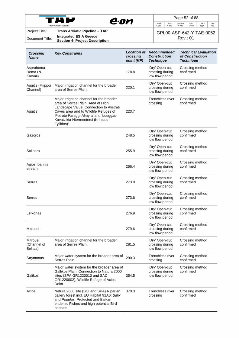
Page 52 of 88
Area Code
Comp. Code
System Code
Disc. Code
Doc.- Type
Ser. No.
Project Title: Trans Adriatic Pipeline – TAP GPL00-ASP-642-Y-TAE-0052Rev.: 01 Document Title: Integrated ESIA Greece
Section 4- Project Description
Crossing Name
Key Constraints Location of crossing point (KP)
Recommended Construction Technique
Technical Evaluation of Construction Technique
Asprohoma Rema (N. Karvali)
178.8
‘Dry’ Open-cut crossing during low flow period
Crossing method confirmed
Aggitis (Filippoi Channel)
Major irrigation channel for the broader area of Serres Plain. 220.1
‘Dry’ Open-cut crossing during low flow period
Crossing method confirmed
Aggitis
Major irrigation channel for the broader area of Serres Plain. Area of High Landscape Value. Connection to Alistrati Caves area and to Wildlife Refuges of 'Petroto-Faraggi-Almyra' and 'Louggas-Kavatzikia-Ntermentersi (Krinidos - Fyllidos)'.
223.7
Trenchless river crossing
Crossing method confirmed
Gazoros
248.5 ‘Dry’ Open-cut crossing during low flow period
Crossing method confirmed
Solinara
255.9 ‘Dry’ Open-cut crossing during low flow period
Crossing method confirmed
Agios Ioannis stream
266.4
‘Dry’ Open-cut crossing during low flow period
Crossing method confirmed
Serres
273.0 ‘Dry’ Open-cut crossing during low flow period
Crossing method confirmed
Serres
273.6 ‘Dry’ Open-cut crossing during low flow period
Crossing method confirmed
Lefkonas
276.9 ‘Dry’ Open-cut crossing during low flow period
Crossing method confirmed
Mitrousi
279.6 ‘Dry’ Open-cut crossing during low flow period
Crossing method confirmed
Mitrousi (Channel of Belitsa)
Major irrigation channel for the broader area of Serres Plain. 281.5
‘Dry’ Open-cut crossing during low flow period
Crossing method confirmed
Strymonas Major water system for the broader area of Serres Plain 290.3 Trenchless river
crossing Crossing method confirmed
Galikos
Major water system for the broader area of Gallikos Plain. Connection to Natura 2000 sites (SPA GR1220010 and SAC GR1220002), Wildlife Refuge of Axios Delta
354.5
‘Dry’ Open-cut crossing during low flow period
Crossing method confirmed
Axios Natura 2000 site (SCI and SPA) Riparian gallery forest incl. EU Habitat 92A0: Salix and Populus Protected and Balkan endemic Fishes and high potential Bird habitats
370.3 Trenchless river crossing
Crossing method confirmed

Page 53 of 88 Area Code
Comp. Code
System Code
Disc. Code
Doc.- Type
Ser. No.
Project Title: Trans Adriatic Pipeline – TAP GPL00-ASP-642-Y-TAE-0052Rev.: 01 Document Title:
Integrated ESIA Greece Section 4- Project Description
Crossing Name
Key Constraints Location of crossing point (KP)
Recommended Construction Technique
Technical Evaluation of Construction Technique
Vardarovasi Riparian gallery forest incl. EU Habitat 92A0: Salix and Populus
372.3 Trenchless river crossing
Crossing method confirmed
Three channels which are tributaries of the Loudias
Several Protected fish species in Lodias and channels (endemic incl. Annex 2 of EU Habitats Directive)
393.7-394.9 ‘Dry’ Open-cut crossing during low flow period
Crossing method under review by design team
Channel 66 EU Habitat 92A0: Salix and Populus inside the dykes, Protected and Balkan endemic fish species incl. incl. Annex 2 of EU Habitats Directive
414.9 Trenchless river crossing
Crossing method confirmed
Grammatiko Creek (dries out in summer)
Habitat 92C0: Platanus orientalis (Very good conservation status of tree canopy stands along the Watercouse) plus nearby presence of protected flora (in total therefore a strong constraint with regard to EBRD PR6)
444.0 Trenchless river crossing
Crossing method under review by design team*
Aliakmonas I Riverine Forests with well-preserved Priority Habitat 91E0: Alnus and Fraxinus (at 50 meters distance upstream from centreline)
Habitat 92A0: Salix and Populus (crossed), Protected and Balkan endemic fishes, Use by bears as corridor, Traces of otter. Nearby presence of protected flora (the whole river section has Natura 2000 site qualities, therefore a strong constraint with regard to EBRD PR6)
521.3 Trenchless river crossing
Crossing method under review by design team*
Aliakmonas II Habitat 92A0: Salix and Populus (mainly on the left bank (north). Protected and Balkan endemic fishes. Nearby presence of protected flora. Great importance as corridor of fauna. Traces of otter, bear presence confirmed by radiotelemetry data. (therefore a strong constraint with regard to EBRD PR6)
528.0 Trenchless river crossing
Crossing method under review by design team*
Aliakmonas III Priority Habitat 91E0: Alnus and Fraxinus. Protected and Balkan endemic fishes. Nearby presence of protected flora. Traces of otter (therefore a strong constraint with regard to EBRD PR6)
532.4 Trenchless river crossing
Crossing method under review by design team*
*Open-cut crossing method is preferred for technical reasons. However, trenchless river crossing methods will be applied if the feasibility of the method has been proven and agreed with the relevant watercourse authority. Source: ENT (2013) Open Cut Method for Large River Crossings
Large rivers are generally crossed by excavating an open trench and installing a siphon (see
Figure 4-23 in Annex 3.6).

Page 54 of 88 Area Code
Comp. Code
System Code
Disc. Code
Doc.- Type
Ser. No.
Project Title: Trans Adriatic Pipeline – TAP GPL00-ASP-642-Y-TAE-0052Rev.: 01 Document Title:
Integrated ESIA Greece Section 4- Project Description
The pipe trench is excavated by means of excavators operating from floating pontoons.
The defined height and the width of the pipe trench are continuously monitored and documented
by means of echo soundings. The excavated material is stored temporarily in designated and
approved places.
The pipeline section for the river crossing is constructed on the river bank and then pulled into
position using a winch located on the opposite river bank. After checking that the pipeline is in the
correct position, the pipe trench is backfilled and any sheet piles are removed.
Pipes with increased wall thickness and a “reinforced PE coating” are used for the crossings as
they will have to withstand the additional weight of the overlying river bed material and water.
Buoyancy control is achieved by means of a reinforced concrete coating which also serves to
mechanically protect the PE coating during the pulling-in process.
Open Cut Method for Rivers and Streams
In general a temporary passage is erected across the watercourse after preparing the working
strip. This passage principally consists of an earth dam, which, depending on the water level, is
equipped with pipes to ensure the unhindered flow of water. This passage is dimensioned for a
low to medium water flow and is flooded in case of high water levels.
The pipeline section is pre-fabricated on the river bank together with its concrete casing.
The trench is then excavated across the watercourse to accommodate the pipeline. Excavation of
the trench is likely to make the water turbid. However, in the smaller streams with a surface width
of between 3-5 m this turbidity will last for approximately half a day only. For bigger crossings
sediment curtains can be installed in order to prevent the sediment plume from travelling
downstream. Specific measures, such as sediment barriers, and seasonal limitations such as
construction only in low flow conditions, are usually implemented to minimise the mobilisation of
fine particulate materials downstream.
The prefabricated section of pipeline will then be lifted into place and the pipe trench s backfilled
using the stored excavation material. This will again make the water turbid, with the duration of
the work being limited to a few hours for smaller streams. In streams where an infiltration from
the river into the groundwater is possible, clay barriers at the river banks are used to seal the
pipeline trench. The river bed is then restored to its original state.
The river banks are then restored incorporating stabilisation of the river bank slopes (erosion
control systems) (See Figure 4-24 in Annex 3.6 – Technical Drawings – Working Strip,
Construction Methods and Crossings). Slope stabilisation is dimensioned according to the
expected flood runoff, with bank protection being defined as a function of the water depth and the
inclination of the water run. In order to construct bank protection in accordance with ecological

Page 55 of 88 Area Code
Comp. Code
System Code
Disc. Code
Doc.- Type
Ser. No.
Project Title: Trans Adriatic Pipeline – TAP GPL00-ASP-642-Y-TAE-0052Rev.: 01 Document Title:
Integrated ESIA Greece Section 4- Project Description
aspects, natural measures for stabilising the river bank are given preference. When stones are
used to stabilise the river bank, they are subsequently covered with humus to facilitate a natural
vegetation cover.
The type and number of river crossings in Greece are summarised in Table 4-13.
Table 4-13 Type and Number of River Crossings
Classification RVX-1 RVX-2 RVX-3 RVX-4
Description Nomination Large River, Lakes
Rivers Streams Seasonal Brooks
Width [m] >50 ≥50 and ≤12 <12 -
Design Installation Method Open Cut or Trenchless
Open Cut Open Cut Open Cut
Special Protection Concrete Coating Concrete Coating/ Weighting
Concrete Coating/ Weighting
No. of Crossings in Greece
16 26 304 [To Be Confirmed at later stage]
Trenchless Method for Rivers and Streams
Although the open cut method is also the preferred method for the larger rivers which have
significant width, large water volumes and sensitive ecosystems downstream, if soil conditions
allow, HDD will be employed, or alternatively microtunneling which is another trenchless crossing
method.
A description of HDD (also known as microtunneling) is presented below. The HDD tunnelling
method is illustrated in Figure 4-25 in Annex 3.6 – Technical Drawings – Working Strip,
Construction Methods and Crossings.
HDD is a trenchless crossing method which begins with boring a small diameter, horizontal hole
(pilot hole) under the crossing obstacle (e.g. a river) with a steel drill rod. When the steel drill rod
emerges on the opposite side of the crossing, a special cutter, called a back reamer, is attached
and pulled back through the pilot hole. The reamer bores out the pilot hole so that the pipe can
be pulled through. The pipe is usually pulled through from the side of the crossing opposite the
drill rig.
Usually a drilling mud, such as fluid bentonite clay (an inert, non-toxic substance), is forced down
the hole to stabilize the hole and remove soil cuttings. Bentonite provides lubrication to the hole
drilling and also provides stability and support for the bored hole.
Page 56 of 88 Area Code
Comp. Code
System Code
Disc. Code
Doc.- Type
Ser. No.
Project Title: Trans Adriatic Pipeline – TAP GPL00-ASP-642-Y-TAE-0052Rev.: 01 Document Title:
Integrated ESIA Greece Section 4- Project Description
4.4.5.4 Crossing of pipelines and cables
There are several crossings of pipelines and cables. TAP will cross gas pipelines on several
locations. The crossings will mainly underneath by maintaining minimum clearance between the
two objects. A typical is shown in Figure 32 in Annex 3.6 Work strip, Construction Methods and
Crossing.
4.4.5.5 Pipeline Protection and Pipeline Stabilisation against Landslide and Instability
There are many areas that are challenging for a pipeline due to geo-hazards; particularly
landslides, earth flows and erosion gullies. After removing the natural cover for the trench beside
river banks, railway or roads, the terrain needs to be adapted. In hilly areas the strip must be
prepared by excavation or landfill measures. In case of bad ground conditions the slopes needs
to be stabilised and eventually drained. The surface will be established with gravel sand or
stabilised with cement or lime.
Adequate protection measures will also be implemented at river banks to prevent instability and
erosion of the river bank. This will be implemented upstream and downstream of the river
crossings and may include a combination of the installation of vegetation, geotextiles and stones
as appropriate, as illustrated in Figure 4-26 in Annex 3.6 – Technical Drawings – Working Strip,
Construction Methods and Crossings.
For pipeline protection methods e.g. in washout areas, against erosion with sandbags and
concrete slab protection for dirt roads refer to Figure 4-27 in Annex 3.6 – Technical Drawings –
Working Strip, Construction Methods and Crossings.
4.4.5.6 River Bed Laying
River bed laying, i.e. laying of the pipeline in the flow direction of the river under the river bed or
laterally in the bank is not foreseen along the pipeline route in Greece.
Page 57 of 88 Area Code
Comp. Code
System Code
Disc. Code
Doc.- Type
Ser. No.
Project Title: Trans Adriatic Pipeline – TAP GPL00-ASP-642-Y-TAE-0052Rev.: 01 Document Title:
Integrated ESIA Greece Section 4- Project Description
4.4.5.7 Construction in Elevated Areas
In normal terrain most of the excavated material will be used for refilling the trench. However, as
the pipe requires some space in the trench, and, depending on ground conditions, bedding and
padding material must be replaced by suitable filling material, some spare material
(min. 1.5 m³/m) needs to be removed and disposed. A larger amount of material accumulates if
the pipeline is located on elevated mountain areas. The surface of these will be levelled allowing
pipelaying works on a limited but flat working strip. Normally this flat strip will be of permanent
character in order to provide easier access for later inspections or maintenance works.
Sections of construction in elevated areas will be further defined and clearly differentiated from
standard working strip (38 m) width. The use of the minimum working strip (18 m) width will be
investigated for each relevant section. Details will be addressed during the next phase of
engineering.
The related material management concept including identification of potential deposits will be part
of the detail design.
In general, all spare material will be disposed permanently away from the pipeline. The material
will not be pushed off the ridge and dropped on both sides. Preferably it will be transported to a
dedicated area(s) as close as possible but at a location where any impact can be minimised.
Any disposal will be carried out on stable ground, compacted and re-naturalized (covered with
local topsoil and start-up aid for habitat-suitable growth of vegetation) in order to avoid any later
landslides or excessive erosion on the deposit. The shape of the spoil deposit will be profiled and
landscaped in order to minimise any impact on visual amenity.
4.4.5.8 Construction in Areas with High Water Table
For construction in areas of high groundwater table, the pipe trench will require dewatering to
ensure a dry work zone. The new pipeline will be fitted with buoyancy control in the form of either
concrete weighting or a piled foundation to prevent the pipeline from floating on the water table
during operation.

Page 58 of 88 Area Code
Comp. Code
System Code
Disc. Code
Doc.- Type
Ser. No.
Project Title: Trans Adriatic Pipeline – TAP GPL00-ASP-642-Y-TAE-0052Rev.: 01 Document Title:
Integrated ESIA Greece Section 4- Project Description
4.5 Construction of Block Valve Stations
4.5.1 Location
The number of block valve stations (BVSs) is not finally defined. At this stage of engineering
there will be approximately 22 BVSs with a maximum distance of 30 km. Final design (e.g.
number and distance between BVSs) will be performed later and depends on pipeline Preliminary
Risk Assessment, accessibility, national and international standards and an agreed operation and
maintenance concept. A BVS will require approximately 702 m2 of land and site access, Figure 4-
28 and Figure 4-29 in Annex 3.5 – Technical Drawings – Layouts and Flow Diagrams illustrates a
typical layout and access arrangements.
Aboveground components of the remotely operated valves will only be some monitoring
components and energy supply equipment (diesel emergency generators and solar panels), all
fenced.
4.5.2 Layout and Configuration
An example of a typical fence and layout of a BVS is illustrated in Figure 4-28 in Annex 3.5 –
Technical Drawings – Layouts and Flow Diagrams.
4.5.3 Construction Duration and Timing
The construction of the BVS will be in line with the pipeline construction period which will take
approximately 36 months. A detail engineering, construction and commissioning schedule for the
BVS needs to be developed in the detail design phase.
4.5.4 Construction Method
The following construction steps are usually recognised in such facilities:
Preparation of the construction site;
Earthworks;
Preparation of foundations;

Page 59 of 88
Area Code
Comp. Code
System Code
Disc. Code
Doc.- Type
Ser. No.
Project Title: Trans Adriatic Pipeline – TAP GPL00-ASP-642-Y-TAE-0052Rev.: 01 Document Title: Integrated ESIA Greece
Section 4- Project Description
Erection of equipment and building;
Laying of cables and electrical works;
Piping and mechanical works;
Installation of operational and instrumentation systems.
4.5.5 Construction Equipment
Table 4-14 describes the equipment is expected to be used for the construction of BVSs. Table 4-14 Equipment Expected to Be Used for the Construction of BVSs
Equipment Number
Excavator 1
Crane 50 t / Side boom 1
4 wheel – Pick-up 4 Source: GPL00-ILF-100-F-TRP-0003_0D---TAP-FEED-GR-PLN-REP-1575--APPENDIX 3 - Comparison of Logistic Concepts – Greece (05-4-2012)
4.6 Construction of Compressor Station
4.6.1 Location
The locations of Compressor Stations are shown on the maps in Annex 3.2: Route Map of the
Project in Greece and Annex 3.3 - Route Map of the TAP Project Detail.
A new, potentially overhead, MV electricity transmission line and substation will be installed to
meet the electrical power requirements of the compressor stations – subject to a study during the
next stage of detailed engineering. Further details on the electric equipment to be installed in the
compressor station are given in Section 4.8.5.3.
4.6.2 Layout and Configuration
Layout plans of the Compressor Stations are shown in Figure 4-30 in Annex 3.5 – Technical
Drawings – Layouts and Flow Diagrams.

Page 60 of 88 Area Code
Comp. Code
System Code
Disc. Code
Doc.- Type
Ser. No.
Project Title: Trans Adriatic Pipeline – TAP GPL00-ASP-642-Y-TAE-0052Rev.: 01 Document Title:
Integrated ESIA Greece Section 4- Project Description
4.6.3 Construction and Duration and Timing
The construction of a Compressor Station is estimated to take 24 months, although a longer
period is foreseen, including the detailed engineering, levelling of the area and commissioning of
the compressor station. The workforce during construction is estimated to 600 person per station.
The water supply is estimated to 3.75 m3/h. The average and the maximum sanitary waste water
during construction are estimated to 3.75 m3/h and 45.0 m3/h respectively.
4.6.4 Construction Method
The following construction steps are usually recognized in such facilities:
Surveying;
Preparation of temporary facilities such as storage areas, offices and accommodation
facilities;
Preparation of the construction site;
Earthworks;
Preparation of foundations (including piling where required);
Erection of equipment and buildings (installation of underground structures might require
the use of sheet piling for stabilisation of construction pits);
Laying of cables, electrical works;
Piping and mechanical works;
Construction of internal roads and areas (if any);
Installation of operational and instrumentation systems;
Commissioning; and
Operation.
Construction of new roads to facilitate permanent access for construction and operation.

Page 61 of 88 Area Code
Comp. Code
System Code
Disc. Code
Doc.- Type
Ser. No.
Project Title: Trans Adriatic Pipeline – TAP GPL00-ASP-642-Y-TAE-0052Rev.: 01 Document Title:
Integrated ESIA Greece Section 4- Project Description
4.6.5 Construction Equipment
The equipment used for the construction of the compressor stations is comprised mainly of the
conventional construction equipment described in Section 4.3.3.
4.7 Use of Resources and Environmental Interferences during Construction and
Pre-Commissioning
4.7.1 Introduction
No construction materials will be taken from work sites or the surrounding environment other than
where specifically approved in advance by the responsible authority. Forested areas, as well as
any other valuable environmental resources, have been avoided to the extent possible during
route refinement process and specific mitigation / preventive measures (e.g. narrowing of working
strip) will apply where feasible.
The use of resources and environmental interferences, as presented in the following sections, will
be reduced as much as is practicably possible:
Temporary Land Take (Section 4.7.2);
Material and Fuel Usage (Section 4.7.3);
Water Consumption (Section 4.7.4);
Air Emissions (Section 4.7.5);
Noise Emissions (Section 4.7.6); and
Liquid and Solid Waste Generation, Handling and Disposal (Section 4.7.7).
4.7.2 Temporary Land Take
During construction, land will be needed for:
construction camps including storage and parking;
pipe yards including storage and parking;
access roads and site access;
Temporary infrastructure (e.g., workshop for equipment repair, administration buildings,
concrete plants).

Page 62 of 88 Area Code
Comp. Code
System Code
Disc. Code
Doc.- Type
Ser. No.
Project Title: Trans Adriatic Pipeline – TAP GPL00-ASP-642-Y-TAE-0052Rev.: 01 Document Title:
Integrated ESIA Greece Section 4- Project Description
The working strip for pipeline construction will in general be 38 m, with the option to reduce this to
28 m (defined as reduced working strip) where required by socio-economic or environmental
conditions, or where technical restrictions apply. Additional space is usually required at road or
river crossings or when required by terrain or soil conditions. For construction in elevated areas
the working strip will be further reduced to a minimum 18 m corridor.
The location of construction sites can usually be adjusted to accommodate any environmental or
social constraints which may exist in the surrounding area. In general, locations that comprise
undeveloped and unused land and are owned by the government will be preferred. There are
certain to be some areas, however, where land that is currently in use will be needed. In such
cases, arrangements will be made to preserve essential access and rights of way during the
construction period and to compensate owners and users, in line with the Livelihoods Restoration
Plan to be developed by TAP AG (see Section 9.3.12).
After construction, most sites will be restored to their original condition where possible. Along the
route a permanent Pipeline Protection Strip (PPS) with a width of 8 m (4m either side of the
centreline) will be established. Farming of annual crops and associated shallow ploughing down
to a maximum depth of 30 cm will be allowed, but cultivation of deep routing system plants such
as vineyards, fruit trees, or any other bushes or trees will be restricted. Similarly, no houses or
construction will be allowed. Exceptions will be made where, after consultation with the relevant
authorities and stakeholders, a decision is made to hand over the facility built during Project
construction (for example a road, well, or building) to be maintained for the use of the local
population.
The following table (Table 4-15) summarizes the land required by the Project during construction
and their locations, are shown on the maps in Annex 3.2 Route Map of the TAP Project in Greece
and Annex 3.3 – Route Map of the TAP Project Detail.

Page 63 of 88 Area Code
Comp. Code
System Code
Disc. Code
Doc.- Type
Ser. No.
Project Title: Trans Adriatic Pipeline – TAP GPL00-ASP-642-Y-TAE-0052Rev.: 01 Document Title:
Integrated ESIA Greece Section 4- Project Description
Table 4-15 Land Take of the Project during Construction
Project Component Temporary Land Take
Pipeline (~543 km) Working Strip Max. 38 m working strip 20,634,000 m² (~2,634 ha)
Access Roads
(Upgrade 29.6 km, 9 m width)
[Note: no new roads required]
29.6 km upgraded = 266,400 m² (27 ha)*
Compressor Station Site (including safety stand-off) 360,000 m² (36 ha) each**
Block Valve Stations (about 22) 18 m x 39 m = 702 m² fenced area each (15,444 m² or ~1.55 ha in total)*
Pipeline Construction Camps (8)** 50,000 m² per camp (400,000 m² or 40 ha in total)
Compressor station Construction Camps (2) 10,000 m² per camp (20,000 m² or 2 ha in total)
Pipe Yards (17) 589,000 m² in total (~59 ha). Individual pipe yard areas given in Table 4-4
River crossing n/a (case by case)
Road crossing n/a (case by case)
* Land take during construction will remain occupied by the Project component during operation until the decommissioning phase (when the structures are likely to be removed and the land reinstated to its former use). Permanent Project land take is given in Table 4-24 ** Temporary land take required for the compressor station construction camp (including an area for worker accommodation) will be included within the compressor station site boundary. Temporary land take for construction camps at special crossings and the BVSs is expected to be approx. 2,500 m² at each site, accommodating 10 to 20 workers during the construction time of a few weeks or months. This land take is included within the pipeline working strip. Source: GPL00-ILF-100-F-TRP-0003_00---TAP-FEED-GR-PLN-REP-1575--APPENDIX 3 - Comparison of Logistic Concepts – Greece (05-04-2012)
4.7.3 Material and Fuel Usage
4.7.3.1 Aggregate Materials
In order to avoid any damage to the pipeline coating, the bottom of the trench as well as the
padding material consist of well graded, round material with an estimated volume of 3,000 m³/km
of pipeline route. If the excavated material from the trench is suitable (e.g. sandstone) it will be
recycled for bedding and padding. Additional padding material will be provided in areas where
flysch is encountered.
Sand and aggregate will be obtained from local designated and approved quarries. The following
options were considered for supply, in order of preference:
Existing Sand Pits: If existing pits are available at a reasonable distance from the
construction site, padding material shall be organised from existing licensed pits.
Sand mining in river beds: Well-rounded and suitable material may be excavated from river
beds. Special care shall be taken in order to avoid any consequential damage associated
with flooding and sedimentation. An official permit must be available upfront.

Page 64 of 88 Area Code
Comp. Code
System Code
Disc. Code
Doc.- Type
Ser. No.
Project Title: Trans Adriatic Pipeline – TAP GPL00-ASP-642-Y-TAE-0052Rev.: 01 Document Title:
Integrated ESIA Greece Section 4- Project Description
Where excavation disturbs topsoil, the first layer of excavated material (topsoil) will be stored
separately so that it can be replaced on the surface when the excavated area is restored.
An Aggregate Management Plan will be developed prior to construction. An outline of this
management plan is provided in Section 9.
4.7.3.2 Other Materials
Various types of materials will be used for Project construction. An estimation of the key materials
consumed during the construction phase is given in Table 4-16. The material types and amounts
are based on similar projects and the current status of design.
Table 4-16 Estimated Material Consumption during Construction
Material Quantity (tonnes)
Steel 420,000
Concrete 12,000
Polyethylene tape (coating) 7,500
Sand 690,000
Compiled by ERM (2012)
4.7.3.3 Fuel Usage
Heavy equipment and motor engine driven equipment used during the construction phase will be
fuelled with diesel. Diesel fuel will be delivered via approved fuel road tankers to the construction
sites. An estimated total volume of fuel required for construction activities is given in Table 4-17.
Table 4-17 Estimated Fuel Consumption during Construction
Fuel Use Quantity (m3)
Diesel Equipment and vehicles 480,000
Compiled by ERM (2012)

Page 65 of 88 Area Code
Comp. Code
System Code
Disc. Code
Doc.- Type
Ser. No.
Project Title: Trans Adriatic Pipeline – TAP GPL00-ASP-642-Y-TAE-0052Rev.: 01 Document Title:
Integrated ESIA Greece Section 4- Project Description
4.7.4 Water Consumption
The foreseen water consumption during construction phase is related primarily to the watering of
the construction sites to reduce dust emissions due earthmoving activities and for civilian uses. In
the commissioning phase, water consumption is related to the hydrotesting activities.
Table 4-18 shows the estimated water consumption during the construction and pre-
commissioning activities.
Table 4-18 Water Consumption
Use Approx. Volume Comments
Civil Water Max 12 m3/day 60 l/person per day
Industrial water 5-10 m3/day Working strip dust suppression
Industrial water Max. 550,000 m3 Hydrotesting *
Industrial water 9,000 m3 trenchless crossings slurry
* Source: GPL00-ΕΝΤ-100-F-TRS-0001_00 – Table with test stations (21-02-2013) and ILF (2012) Hydrostatic Testing Concept - Greece – Ref. GPL00-ILF-100-F-TRS-0001_00 Note: Table 4-11 shows the potential water sources identified along the TAP route and the volumes required for hydrotesting for each main section. (Reuse will reduce this amount significantly)
4.7.5 Air Emissions
During the construction activities, earth dust particles from soil movement, and pollutants from
the exhausts of heavy equipment and vessels will be emitted. The earth dust will be produced
during the excavation and backfilling activities and the earthworks related to the worksites,
compressor station and BVS construction activities. Other sources of dust emission will be the
traffic movements, on the working strip, of trucks, minivans and heavy equipment. Pollutants will
be produced by heavy equipment and vessels due to the fuel combustion in their engines, and
released in the exhausted gas. The main pollutants produced will be NOX, CO, dust and SOX.
Refer to Section 8.3.2 for further detail on construction air emissions and the impact assessment.
4.7.6 Noise Emissions
Typical noise emissions generated by heavy construction equipment at the working strip,
worksites and the compressor station site are listed in Table 4-19. The reported pressure noise
levels at 1 meter from the source are typical for the considered equipment.

Page 66 of 88 Area Code
Comp. Code
System Code
Disc. Code
Doc.- Type
Ser. No.
Project Title: Trans Adriatic Pipeline – TAP GPL00-ASP-642-Y-TAE-0052Rev.: 01 Document Title:
Integrated ESIA Greece Section 4- Project Description
Table 4-19 Typical Noise Levels for Construction Equipment
Type of Equipment Power Noise Level
Excavator 70 - 84 dBA
Backhoe loader 70 - 84 dBA
Crane 70 - 84 dBA
Side-boom 84 - 99 dBA
Pipe bending machine 60 dBA
Engine generator 70 - 84 dBA
Pay-welder 70 - 84 dBA
Compiled by ERM (2012)
During the pre-commissioning phase, the main noise sources are compressors and pumps
foreseen for the hydrotesting activities.
The typical pressure noise levels at 1 meter from the source are typical for the considered
equipment and are shown in Table 4-20.
Table 4-20 Typical Noise Levels for Pre-commissioning Equipment
Equipment Power Level
Engine driven pump 84 - 99 dBA
Engine driven compressors 99 -115 dBA
Compiled by ERM (2012)
The noise emissions generated during the construction phase by construction equipment are
identified in the assessment section of the ESIA - refer to Section 8.3.2.
4.7.7 Liquid and Solid Waste Generation, Handling and Disposal
4.7.7.1 Waste Management
In general, it should be stated that waste management will be carried out closely in line with the
legal framework and under consideration of international best practice principles.
All waste materials will be collected, stored and transported separately in appropriate and
approved bins and containers.
Companies certified by the relevant authorities will be used for transportation, recycling and
disposal of waste. A list of certified waste management companies has been obtained from the
Ministry of Energy, Environment and Climate Change (MEECC), which identifies that it will be

Page 67 of 88 Area Code
Comp. Code
System Code
Disc. Code
Doc.- Type
Ser. No.
Project Title: Trans Adriatic Pipeline – TAP GPL00-ASP-642-Y-TAE-0052Rev.: 01 Document Title:
Integrated ESIA Greece Section 4- Project Description
possible to manage and dispose of all the likely construction and operation waste streams at
facilities within Greece. This process will be closely coordinated with the responsible authorities.
The overall objective is to minimise the impacts of waste generated during the construction phase
through the following:
minimise the amount of waste that is generated;
maximise the amount of waste that is recovered for recycling – including segregation of
recyclable wastes at source;
minimise the amount of waste that is deposited at landfill;
ensure any hazardous wastes (e.g. used oils, lead-acid batteries) are securely stored and
transferred to appropriate facilities;
avoid dust impacts from handling of construction wastes;
ensure all wastes are properly contained, labelled and disposed of in accordance with local
regulations; and
waste is disposed of in accordance with the waste management hierarchy in order of
preference as follows, reduce, re-use, recycle.
The construction waste management strategy will incorporate the following ‘good site practices’
which will reduce the risk of impacts arising from waste management activities. The construction
waste management plan will cover the following key aspects:
develop inventory and schedule of likely wastes;
assessment of local waste management facilities;
waste minimisation principles;
maximise reuse/recycle opportunities;
waste segregation (liquid and solid/reusable and recyclable);
waste collection, storage and transfer;
specific disposal procedures for all waste steams identified including waste transfer notes if
moved to a licensed offsite facility;
auditing and reporting procedures; and
closure process which will include appropriate monitoring and recording.

Page 68 of 88 Area Code
Comp. Code
System Code
Disc. Code
Doc.- Type
Ser. No.
Project Title: Trans Adriatic Pipeline – TAP GPL00-ASP-642-Y-TAE-0052Rev.: 01 Document Title:
Integrated ESIA Greece Section 4- Project Description
Most of the excavated soil will be used to backfill the pipeline trench. Excess soil will likely be
spread out and contoured along the route in agreement with competent authorities and according
to further engineering studies. Wastewater and solid waste from the construction camps will also
be generated. Wastewater package treatment units will be installed at the construction camps.
Treated effluent will be discharged to local evaporation ponds and sewage sludge will be dried
and land filled.
Waste generated during construction is likely to be classified into four categories for disposal as
summarised in Table 4-21. Detailed lists of the quantities of waste by type are shown in Table 4-
22.
Table 4-21 Categories of Waste Generated During Construction and Pre-commissioning
Inert Domestic Oily and Hazardous Liquid
These will include: earth (not including excavated material, which is destined to be backfilled when the area is restored), building rubble, unused construction material etc generated during preparation and restoration of worksites. These wastes pose no risk of pollution, but may be unsightly and need to be disposed of at a controlled disposal site.
The offices and administration buildings associated with the worksites (as well as the construction camps) will generate amounts of ‘domestic’ types of waste (ie, food waste, paper and packaging etc). This will be transported to a controlled municipal waste disposal site.
These will include: the oily wastes associated with vehicle maintenance (waste oil, material collected from waste water interceptors etc); unused or waste chemicals, paints and solvents; materials excavated from contaminated sites (if any); and, any other wastes, sludge or debris that are unsuitable for disposal in a municipal type landfill. Such wastes will be segregated for collection and disposal by specialist contractors at sites that are equipped and approved for such wastes.
These will include:
Hydrotest water from the pipeline sections (refer to Section 4.4.4);
“Black” and “grey” water from construction camps;
Hazardous liquid wastes (e.g. oils, solvents etc);
Rainwater runoff from sealed surfaces and roofs; and
Tunnelling machines cooling water.
4.7.7.2 Waste Types and Amounts
Table 4-22 describes the typical waste types generated by the construction of the pipeline.
Generated waste types and estimated quantities are an assumption based on experience gained
from similar projects and the current status of design. During construction +/- deviations are
possible.

Page 69 of 88 Area Code
Comp. Code
System Code
Disc. Code
Doc.- Type
Ser. No.
Project Title: Trans Adriatic Pipeline – TAP GPL00-ASP-642-Y-TAE-0052Rev.: 01 Document Title:
Integrated ESIA Greece Section 4- Project Description
Table 4-22 Typical Wastes Generated during the Construction and Pre-commissioning of the Pipeline
Activity Waste Generation Approximate Quantity* Disposal Recommendation
Construction sites/pipe yards/construction camps:
Site preparation Likely to be negligible. - -
Operation of construction site
Office rubbish, paper, canteen refuse etc.
(Included in rubbish from yard).
Recycle where possible and send rest to a licensed waste disposal site.
Rubbish from pipe yards and construction sites.
45 tonnes per week. Collect in covered skips to recycle where possible or send to a licensed waste disposal site.
Scrap metal. 45 to 270 tonnes. Recycle or sell as scrap.
Sewage. 24 tankers per month. Cesspit to sewer or emptied regularly.
Site reinstatement Workshop waste, e.g. paints, oil etc.
45 tonnes. Collect in secure containers and send to a licensed waste treatment or disposal site.
Concrete foundations etc. up to 600 tonnes. Send to licensed waste disposal site.
Pipeline Construction:
Working width preparation
Hedges, timber, vegetation, fence posts, wire etc.
- In accordance with applicable legislation
Pipe-string and bending
Pipe-bands and end caps. - Collect in skips and send to licensed waste disposal or recycling site.
Welding, testing and coating
Spent welding rods, grinding wheels, visors, shot-blast.
5 to 10 tonnes per week and per construction spread.
Collect in covered skips or tipper trucks and send to licensed waste disposal site.
Trenching, lowering and laying of the pipeline
Soil and rock Approx. 2,400.000 m³ for the whole pipeline route
Set aside to be used in backfilling. Excess quantities used to restore abandoned quarries, in coordination with Authorities
Backfilling and grading
Surplus spoil and rock. up to 3,000 tonnes per day and construction spread (based on 600 m backfilling per day and construction spread), dependant on ground conditions.
Subject to landowner/ occupier’s agreement. Re-use if possible/take to licensed waste disposal site.
Reinstatement Temporary stone roads.
Temporary fencing, gates, troughs etc.
Re-use elsewhere within landholding.
Re-use if possible.
Horizontal Directional Drilling (HDD)
Bentonite, spoil and rock cuttings.
up to 600 tonnes/crossing (dependant on whether used).
Store in sumps or storage pits, then dispose of using road truck tankers to licensed waste disposal site.
Thrust-boring Spoil and rock cuttings. up to 900 tonnes (dependant on whether used).
Dispose of using road truck tankers to licensed waste disposal site.
Mess huts, miscellaneous, etc
Canteen refuse, safety equipment etc.
2,5 to 10 tonnes/week per construction spread
Collect in covered skips and send to licensed waste disposal site.

Page 70 of 88 Area Code
Comp. Code
System Code
Disc. Code
Doc.- Type
Ser. No.
Project Title: Trans Adriatic Pipeline – TAP GPL00-ASP-642-Y-TAE-0052Rev.: 01 Document Title:
Integrated ESIA Greece Section 4- Project Description
Activity Waste Generation Approximate Quantity* Disposal Recommendation
Mobile site toilets Sewage. Approximately 20 emptied weekly per construction spread.
Disposal by appointed waste management contractor.
* Only estimates and estimated ranges for waste quantities can be given at this stage of the Project. The Primary Contractor will refine these estimates when detailed design has been finalised and the locations of the construction sites and storage yards have been defined further.
Table 4-23 describes the Construction Waste Inventory for the TAP in Greece. Waste types and
amounts are an assumption based on similar projects and the current status of design. During
construction +/- deviations are possible.
Table 4-23 Construction Waste Inventory
Waste Type Amount (tonnes) * Waste Type Amount (tonnes) *
Hazardous
NDT waste > 5 Batteries Wet, Batteries Dry
< 6
Rags and oil absorbents 50 Activated carbon < 6
Pipeline coating chemicals < 6 Cables/copper 3
Aerosol cans < 6
Chemicals (Hazardous)
Adhesives < 6 Glycols < 6
General Chemicals 24 Solvents < 6
Freighting foam < 6 Hydro test fluids < 6
Diesel, Fuel and Oil Wastes (Hazardous)
Diesel generator lube oil 10 Light bulbs 6
Misc oils (incl hydraulic) 25 Medical 6
Vehicle & equip lube oil 25 Paint sludge 6
Glycol sludge >5 Paint and cans/brushes 12
Non-Hazardous
Paper and card 50 Welding materials 42
Pipe-bands and end caps 50 Wood 360
Plastic bottles 150 Aluminium cans <6
Plastic 'epoxy' drums 20 Electrical/electronic comps <6
Polystyrene 75 Filters (water) 6
PPE and clothing <24 Food 1,200
Steel 18
Inert (Non-hazardous)
Bricks and building materials
42 Glass <6
Concrete/foundations 75

Page 71 of 88 Area Code
Comp. Code
System Code
Disc. Code
Doc.- Type
Ser. No.
Project Title: Trans Adriatic Pipeline – TAP GPL00-ASP-642-Y-TAE-0052Rev.: 01 Document Title:
Integrated ESIA Greece Section 4- Project Description
4.8 Operation Phase
4.8.1 Operating Philosophy
The pipeline system will be managed by TAP AG, responsible for the transportation of natural
gas from receipt in Greece to delivery in Italy. The operating organisation will be composed of
three local branches, each one incorporated in each of the transit countries. The Supervisory
Control Centre (SCC) will be located in the Pipeline Receiving Terminal (PRT) in Italy. The SCC
will be designated to act as the main control centre, with unmanned control units as back-up at
Compressor stations.
The primary objective of the operating and control philosophy to be developed for the TAP
system is to provide the basis for safe, reliable and efficient pipeline operation with an optimum of
operations and maintenance personnel, consistent with current practices in the pipeline industry.
The scope covers:
Common functionality of the entire TAP system;
Control modes;
Pipeline operation, based on station operation;
Leak detection, batch/pig tracking, simulation, scheduling, etc.;
Compressor station functionality;
Compressor station operation;
Compressor station safety;
At each compressor station there will be an Integrated Control and Safety System (ICSS)
comprising a Station Control System (SCS) and an integrated Emergency Shutdown system
(ESD). In addition there is a separate Fire and Gas (F&G) sub-system. Each of these systems
will communicate via a fibre optic based telecommunication system running the entire length of
the pipeline.
4.8.2 Operation Control System
The TAP control system will permit full operational monitoring and control from the one control
centre in Italy. The control centre will be able to control the operation of the main pipeline;

Page 72 of 88 Area Code
Comp. Code
System Code
Disc. Code
Doc.- Type
Ser. No.
Project Title: Trans Adriatic Pipeline – TAP GPL00-ASP-642-Y-TAE-0052Rev.: 01 Document Title:
Integrated ESIA Greece Section 4- Project Description
however, additional control centres at a CS will be able to substitute tasks from the main control
centre, for contingency.
Detailed operating procedures for the pipeline system will be developed. These procedures will
be in place ahead of pipeline operation. The operating procedures will typically address the
following:
An administrative system covering legal considerations, work control and safety;
Clear and effective emergency procedures and operating instructions;
Adequate and regular training of all personnel involved in operational and maintenance
issues;
A comprehensive system for monitoring, recording and continually evaluating the condition
of the pipeline and auxiliary equipment (BVS etc);
A system to control all development or work in the vicinity of the pipeline;
Effective corrosion control and monitoring;
A system to collect and collate information on third party activities;
Monitoring of restoration, and the undertaking of remedial work as necessary.
The pipeline will be monitored and controlled 24 hours a day and 365 days a year from a central
control room. The monitoring system is a SCADA System (System Control and Data Acquisition).
During operation, leak detection will be by continuous measurements of pressure and flow rates
at the inlet and outlet of the stations and pipeline. If a leak is detected, an alarm is triggered. To
allow internal inspection, pigging facilities will be installed. The pipeline system has been
designed to allow use of instrumented pigs.
4.8.3 Operational Pipeline Safety
4.8.3.1 Cathodic Protection Installation
Passive protection will be installed, consisting of an outside pipeline coating made of high-density
extruded polyethylene tape, minimum thickness 3 mm, applied directly in the factory, in
combination with an inner epoxy coating. Welding joints shall be coated with heat-shrinkable
tape.

Page 73 of 88 Area Code
Comp. Code
System Code
Disc. Code
Doc.- Type
Ser. No.
Project Title: Trans Adriatic Pipeline – TAP GPL00-ASP-642-Y-TAE-0052Rev.: 01 Document Title:
Integrated ESIA Greece Section 4- Project Description
Active cathodic protection (a technique used to control the corrosion of a metal surface by
making it the cathode of an electrochemical cell), will be provided through the impression of an
electric flux by means of devices located along the line, which keep the steel pipe at a potential
lower than the surrounding soil and water. The cathodic protection system is installed at the
same time as the pipeline laying, connecting it to one or more cathodic protection units,
consisting of equipment which automatically keeps the pipe at a negative or at -1 V potential
lower than the reference electrode (Cu-CuSO4). The cathodic protection system will be remotely
monitored by the System Control and Data Acquisition (SCADA) system.
4.8.3.2 Leak Detection System (LDS)
The pipeline will be monitored by a leak detection system (LDS) that operates on the basis of
flow, pressure and temperature monitoring, thereby detecting losses on an automatic basis.
Undetected leaks are now a rare occurrence in modern gas pipelines as leak detection systems
allow immediate notification and action in an emergency.
The control system will include a dynamic real time model which supports a number of functions
such as leak detection, batch tracking, pig tracking, online and offline simulation. Online
simulation should monitor the real process and provide a basis for the LDS, whereas the offline
simulation will be available for operator training.
The LDS must be able to detect and localise leaks within a short time. In order to ensure
reliability, a combination of at least two independent methods is foreseen. Key summary
information will be presented on the SCADA in the Supervisory Control Centre (SCC).
This information will serve to alert the operator of the existence of a potential leak and provide
operational assistance however it will not initiate any automatic shutdown.
4.8.3.3 Marking of Pipeline
The laid pipeline will be permanently marked by pipeline and aerial markers during the operation
phase. In addition, warning tape will be laid above the pipeline in the trench. Figure 4-16 in Annex
3.4 – Technical Drawings – Construction Activities shows photographs of a typical marker and
the appearance of the reinstated route.

Page 74 of 88 Area Code
Comp. Code
System Code
Disc. Code
Doc.- Type
Ser. No.
Project Title: Trans Adriatic Pipeline – TAP GPL00-ASP-642-Y-TAE-0052Rev.: 01 Document Title:
Integrated ESIA Greece Section 4- Project Description
4.8.3.4 Block Valve Stations
During normal operation pipeline safety will be operated by a centrally controlled SCADA
Systems. It will, however, also be possible to operate the pipeline safety systems from each
compressor station. The pipeline will be operated 7 days a week, 24 hours per day. Permanent
operators will operate/monitor the pipeline at SCC on a shift basis.
The pipeline will be sectioned by BVSs, located in accordance with the Risk Assessment, which
will be undertaken at the later stages of engineering. Their purpose is to isolate sections of the
pipeline between two adjacent line valves, either for maintenance or for protection, in case of
emergency. BVSs can only be closed remotely, and can only be re-opened locally.
In addition Controlled Emergency Operation Shut Down (CEOSD) procedures will be developed,
which define the particular operational measures to be taken in case of leak or threat of any kind
at each location of the entire pipeline system. COESD procedures will be manually implemented,
but supported by status and alarm signals generated by the SCADA.
4.8.3.5 Data Management
The SCADA system at the Supervisory Control Centre (SCC) will permanently and automatically
record the actual status and historical trends of process variables in a database and on the
control screens. Alarm and events will be displayed at the respective Local Control Centre (LCC);
critical and/or relevant combined alarms from manned stations, as well as necessary alarms and
status signals from non-manned stations, will be transferred to the SCADA at the SCC.
4.8.4 Pipeline Maintenance
The pig launcher and pig receiver facilities at the compressor stations inlet will be provided for
periodic cleaning, wax removal, and periodic inspection of the pipeline (determination of possible
corrosion rate, wall thickness and inner surface diagnostics). Pig launching and receiving will be
manual operation accompanied by a pig tracking system.
Furthermore, a Pipeline Integrity Management System (PIMS) will be developed to control
ongoing monitoring/maintenance during system operation, with special focus on corrosion
control.

Page 75 of 88 Area Code
Comp. Code
System Code
Disc. Code
Doc.- Type
Ser. No.
Project Title: Trans Adriatic Pipeline – TAP GPL00-ASP-642-Y-TAE-0052Rev.: 01 Document Title:
Integrated ESIA Greece Section 4- Project Description
The roads that will be used to access the pipeline for maintenance will be the same as those
used in construction activities.
4.8.5 Compressor Station
4.8.5.1 Monitoring Facilities
A metering system will be installed in the compressor station which measures the gas flow rate
for the purpose of operational control, and as basis for the leak detection system of the main
pipeline. The workforce during operation is estimated to 25 persons per station.
4.8.5.2 Fire Fighting System
The water fed fire fighting system will be installed generally in accordance with European
standards(e.g. EN 14384 “Pillar fire hydrants”, EN ISO 14557 ”fire fighting hoses”, EN 671-1
“Fixed fire fighting systems – hose systems”, EN 14462 “Water conduit for fire extinguishing –
planning and installation of fire hose systems and water conduit for fire extinguishing”, EN 1028
“Installation of Stationary Pumps for Fire Protection”, “Private Fire Service Mains and Their
Appurtenances (combined with EN 1988-6)” and EN 1947: Fire Fighting Hose Systems.)
It will be equipped with pillar hydrants and an electrical plus additional diesel driven fire water
pumps.
Fire water will be stored in one tank with a working capacity of approximately 450 m³. This is a
sufficient volume to fight fires in comparable compressor stations in Germany.
4.8.5.3 Electrical Power Supply
Power requirements of the compressor station will be met by a new MV electricity transmission
line and substation which will connect the installations with the MV network in the area, and by a
gas engine driven and a diesel driven power generator as back-up. The following electrical
systems will be installed:

Page 76 of 88 Area Code
Comp. Code
System Code
Disc. Code
Doc.- Type
Ser. No.
Project Title: Trans Adriatic Pipeline – TAP GPL00-ASP-642-Y-TAE-0052Rev.: 01 Document Title:
Integrated ESIA Greece Section 4- Project Description
gas engine driven power generation;
diesel engine driven power generation;
high - medium - low voltage transformers, switchgear;
emergency power supply;
uninterruptible power supply;
grounding and lightning protection;
building installations; and
outdoor lighting; etc.
The compressor station will contain electrical circuits with the following voltages:
Medium voltage three phase AC system
400 V three phase AC system (main power system)
400 V three phase AC emergency power system
230 V single phase AC UPS system
110 V DC UPS system
24 V DC UPS system
The electricity demand of the shore facilities is estimated at approximately 800 kW and BVSs
require approximately 25 kW. Here the electricity demand will be met via the public grid
supported by emergency power supply and backup provisions as followed:
GCS00 has the following components:
Phase 10 bcm/year (2 operating +1 spare):
Gas Engine Power Generator (back-up for main grid): 2,500 kVA (= 2,000 kW, = 2 MW)
Diesel Engine Power Generator (back-up for gas engine power generator): 2,500 kVA (= 2,000
kW = 2 MW)
Emergency Diesel Power Generator (for UPS) 2 x 125 kVA (= 2 x 100 kW, = 2 x 0.1 MW)
Diesel Tank (24 m³)

Page 77 of 88 Area Code
Comp. Code
System Code
Disc. Code
Doc.- Type
Ser. No.
Project Title: Trans Adriatic Pipeline – TAP GPL00-ASP-642-Y-TAE-0052Rev.: 01 Document Title:
Integrated ESIA Greece Section 4- Project Description
Phase 20 bcm/year (5 operating +1 spare):
Gas Engine Power Generator (back-up for main grid): 2 x 2,500 kVA (= 2 x 2,000 kW = 2 x 2
MW)
Diesel Engine Power Generator (back-up for gas engine power generator): 2 x 2,500 kVA (= 2
x 2,000 kW = 2 x 2 MW)
Emergency Diesel Power Generator (for UPS) 2 x 200 kVA (= 2 x 160 kW = 2 x 0.16 MW)
Diesel Tank (2 x 24 m³)
GCS01 has the following components (in future):
Phase 20 bcm/year (4 operating +1 spare):
Gas Engine Power Generator (back up for main grid): 1 x 2,500 kVA & 1x 1,600 kVA (= 1
x 2,000 kW & 1 x 1,280 kW = 1 x 2 MW & 1 x 1.28 MW)
Diesel Engine Power Generator (back-up for gas engine power generator): 1 x 2,500 kVA & 1x
1,600 kVA (= 1 x 2,000 kW & 1 x 1,280 kW = 1 x 2 MW & 1 x 1.28 MW)
Emergency Diesel Power Generator (for UPS): 2 x 160 kVA (= 2 x 128 kW = 2 x 0.128 MW)
Diesel Tank (1 x 40 m³)
4.8.5.4 Diesel and Gas
Diesel will be used for main fire fighting pump, the auxiliary diesel generator and the emergency
diesel generator at the compressor station. It will be delivered by trucks to the main diesel
storage tank which will have a capacity of 24 m3. From here it will be pumped into the smaller
daily tanks of the fire fighting pump, the auxiliary diesel generator and the emergency power
generator. For the diesel generators daily tanks will be provided.
The grid back-up power generation unit will be driven by a gas engine or turbine. Gas
requirements will be sourced from the pipeline at the following approximate rate:
Compressor Stations: 600 Sm³/h
4.8.5.5 Air and Noise Emissions from Compressor Station
Air Emissions
The significant air emission sources are the gas turbine stacks at the compressor stations.
Additional secondary sources of emissions can be considered negligible, and are limited to the

Page 78 of 88 Area Code
Comp. Code
System Code
Disc. Code
Doc.- Type
Ser. No.
Project Title: Trans Adriatic Pipeline – TAP GPL00-ASP-642-Y-TAE-0052Rev.: 01 Document Title:
Integrated ESIA Greece Section 4- Project Description
following: emissions from heating, auxiliary power generation, and the diesel generator, to be
operated only for electrical power supply in cases of emergency.
The concentrations of air pollutants produced by the compressor stations will be in line with the
Greek Environmental Law, based on the EC Directive 2008/50/EC on ambient air quality. For
normal operation 7 the maximum concentrations in the flue gas from the gas turbines will be
< 50 mg/Nm³ 8 for nitrogen oxides (NOX expressed as NO2). This low value is achieved due to the
installation of dry low-NOX burners. Based on the maximum value guaranteed by the gas
supplier, sulphur content in the gas, and thus the gas turbine fuel, is low, and the concentration of
emitted SO2 will be below 5 mg/Nm³.
Emissions of CO2 from the operation of the gas turbine driven compressor will be at the following
approximate rate:
GCS00: 414,020 t/year
GCS01: 536,046 t/year
The venting of natural gas from the depressurisation of the pipeline for maintenance purposes is
estimated to occur once per year at the following approximate rate:
CS00: 230 t/year
CS01: 230 t/year
Noise emissions
The main sources of noise will be at the compressor station sites and include the gas turbines,
turbo compressors, stacks, air ventilation systems, air-cooled heat exchanger, the aboveground
station piping, and the pressure control valves. All relevant noise sources have been evaluated
and compliance with applicable noise limit values has been confirmed. It is therefore expected
that no noise mitigation measures will be needed to ensure that levels are within applicable limits.
However, mitigation measures will be applied on equipment if required so that applicable limit
values are respected. More details are provided in Section 8.3.3 and Annex 8.2 where the results
of noise modelling are documented.
7 Normal operation means a load range between 70 % and 100 % of system capacity 8 Nm³ stands for "normalized cubic meters," which means that the volume referenced to is at a temperature of 273º K and a pressure of 101,3 kPa

Page 79 of 88 Area Code
Comp. Code
System Code
Disc. Code
Doc.- Type
Ser. No.
Project Title: Trans Adriatic Pipeline – TAP GPL00-ASP-642-Y-TAE-0052Rev.: 01 Document Title:
Integrated ESIA Greece Section 4- Project Description
4.8.5.6 Drainage and Effluent Management
General effluent management considerations are described below. The specific drainage and
effluent treatment philosophy at the compressor station is outlined here.
The following types of wastewater were taken into consideration in developing the drainage
philosophy:
uncontaminated storm water;
sanitary wastewater; and
oily water.
The systems for handling these different groups of waste water are outlined in the following.
The figures provided are typical for these calculations, have been proven in a number of projects
executed by the Consultant and will be revisited by the Primary Contractor at the Detailed Design
stage.
The usually allowable value in central Europe for hydrocarbons is 5 mg/l at outlets. This value
can be reached using the Parallel Plate Coalescing Technology. Lower concentrations can be
reached by adding further treatment stages. Using a biological treatment plant, approximately
3 mg/l can be achieved. With an additional polishing pond, values in the range of 1 mg/l can be
reached.
4.8.5.6.1 Rain Water
Rain water and surface water run-off will be non-polluted water arising from the following areas:
building and shelter roofs;
roads and traffic areas; and
areas beside roads and traffic areas.
The rain water system deals with the uncontaminated runoff from roofs of the buildings, roads
and paved areas, as well as from all other areas outside the tank bunds and catchment basins.
Rain water from these areas is considered to be clean water, not requiring any treatment. Based
on EN 752, rain water will be collected by curb stones and gullies in sewerage system and be

Page 80 of 88 Area Code
Comp. Code
System Code
Disc. Code
Doc.- Type
Ser. No.
Project Title: Trans Adriatic Pipeline – TAP GPL00-ASP-642-Y-TAE-0052Rev.: 01 Document Title:
Integrated ESIA Greece Section 4- Project Description
discharged in nearby rivers according to requirements of responsible authorities. If necessary,
retention of rain water is considered with sewer with storage capacity regarding EN 752. For
paved areas an infiltration in substratum is assumed.
The rain water for the Compressor Stations will be discharged to the streams according to the
instructions of relevant Authorities.
The rain water from paved areas and from protected surfaces are estimated to 1170.14 m3/h and
24.30 m3/h respectively.
The rain water system has been designed for a rainfall intensity of 244.4 l/sec/ha and includes an
element of rain water retention/storage. Figure 4-31 in Annex 3.5 – Technical Drawings – Layouts
and Flow Diagrams shows the calculated volumes of rain water that will run off from each zone of
the compressor station and the total volume that will be disposed for the 10 bcm/year and 20
bcm/year operational scenarios. The figure also shows the volumes that will be discharged to an
existing water body and those that will discharge via an infiltration method.
4.8.5.6.2 Sanitary Sewer (Waste Water)
Waste water will arise from the sanitation facilities within the buildings. The water from the
sanitation facilities will be collected within the Waste Water System.
Waste water will be treated on each of the compressor station sites in small sewage works
designed in accordance with DIN EN 12566 and discharged to existing watercourses in
accordance with the requirements of responsible Greek authorities.
The average and the maximum sanitary waste water during operation are estimated to be
0.16 m3/h. Figure 4-31 in Annex 3.5 – Technical Drawings – Layouts and Flow Diagrams
presents flow diagrams for the waste water system at CS and shows the calculated volumes of
waste water produced by each zone of the compressor station for the 10 bcm/year and 20
bcm/year operational scenarios. Diagrams for the waste water system at the Compressor
Stations show the calculated volumes of waste water presents at GCS00 and GCS01. The figure
also shows the total volumes of waste water that will be treated in the treatment plant at each site
for the two operational scenarios. The treated effluent from the sewage treatment plant will be
discharged to an existing water body.
Description of treatment technique of sanitary wastewater:
A fully biological wastewater treatment plant is planned. It cleans the household sanitary
wastewater from the planned sewage system of the station before discharge into a public outfall.

Page 81 of 88 Area Code
Comp. Code
System Code
Disc. Code
Doc.- Type
Ser. No.
Project Title: Trans Adriatic Pipeline – TAP GPL00-ASP-642-Y-TAE-0052Rev.: 01 Document Title:
Integrated ESIA Greece Section 4- Project Description
The wastewater treatment plant is designed as a precast element in the form of an underground
drainage shaft with a 2-chamber system. The first chamber, where the mechanical pre-
purification is located will retain larger inorganic and organic materials. The chamber also
functions simultaneously as a collector for household wastewater. The second chamber is the
activation tank, which is supplied by a predetermined amount of wastewater from the collector.
After completion of the main cleaning process a retirement phase follows in which the bacteria
are allowed to settle on the bottom of the second chamber. Excess bacteria returned in the
settlement storage, where they can be stored until discharged.
The whole cleaning process is automatic. To encourage the passage of the wastewater,
compressed air is used from the ventilation system. The system is controlled by a sound reducing
control unit.
Only the treated water leaves the plant to be discharged into a receiving system or a public
drainage system.
Oily Water
Oily water will arise from the following areas:
oil-water separators;
the catchment areas at the meterings;
the catchment areas at the scraper traps;
pump shelters;
workshops;
pipeline maintenance centre shelter;
fire fighting building; and
fire fighting pump area, etc.
Effluents from floor drains of buildings will be treated by separators before being discharged into
storm water systems. The separator will be designed in accordance with EN-858. In normal plant
operation no oily water occurs, therefore the separators are installed to deal with non-routine or
emergency events.
The treatment description of oily wastewater is as follows:
In principle there is no induction of oily wastewater scheduled on each station.
Page 82 of 88 Area Code
Comp. Code
System Code
Disc. Code
Doc.- Type
Ser. No.
Project Title: Trans Adriatic Pipeline – TAP GPL00-ASP-642-Y-TAE-0052Rev.: 01 Document Title:
Integrated ESIA Greece Section 4- Project Description
The aim is to protect the surface water outside the buildings from the influences of fuel
condensation and environmentally hazardous substances occurred while discharging or filling the
tanks on the station. The waste water will be treated by a coalescence separator and container
according to DIN EN 858. The separators and container are connected with the sanitary sewage
system which is connected to a wastewater treatment plant.
The chosen system is not a treatment system, it’s a protection system. In the event of an
accident during discharging or filling the tanks the system will work to protect the surface water.
In this case the liquid will be collected on a paved protection surface and be transported over
gullies and pipes to the coalescence separator and then to the container where it is to be
discharged in a mobile tank. The liquid has then to be disposed.
Switchgear and Transformer plants are designed according to water and building code
requirements and equipped with restraint systems. Treatment in separators prior to discharge in
storm water sewers is required. In normal plant operation no oily waters occur.
The effluents will be discharged in accordance with IFC standards, as well as EU and Greek
legislation and requirements. Wastewater treatment and disposal will be designed in accordance
with the relevant legislative requirements.
The waste water balance for CS is shown in Figure 4-31 in Annex 3.5 – Technical Drawings –
Layouts and Flow Diagrams. Further commentary is provided in the following sections.
4.8.5.7 Compressor Station Telecommunication System
The compressor stations will be equipped with a Telecommunication System (TCS).
The TCS will be designed to operate under normal conditions with minimum operator actions
required. The system design will provide built-in flexibility for future expansion due to future
addition of compressor buildings. The TCS will normally operate from an external uninterruptible
power supply of 24 V AC.
Telecommunication will be performed via fibre optic cable (SCADA) along the pipeline with a
back-up system. The local antennas for the back-up system are part of the stations.
Voice communication will be via a national telecom grid or carried out by mobile phones.

Page 83 of 88 Area Code
Comp. Code
System Code
Disc. Code
Doc.- Type
Ser. No.
Project Title: Trans Adriatic Pipeline – TAP GPL00-ASP-642-Y-TAE-0052Rev.: 01 Document Title:
Integrated ESIA Greece Section 4- Project Description
4.8.6 Permanent Land Take
Land will be acquired for permanent Project structures and to allow for operation, maintenance
and emergency access throughout the operational life of the Project (refer to permanent land
take in Table 4-24). Areas above the buried pipes may also be purchased or rights acquired so
as to prevent development on the land surface that could cause damage to the pipeline.
A major criterion of the preliminary project design has been that, as far as practicable, permanent
infrastructure should be sited on unused land of no particular ecological or cultural value. Where
this has not been possible, effort has still been made to avoid land on which there are dwellings
or public infrastructure, or which is of high value as a habitat or for agriculture. In addition, site
selection has taken into account access facilities so that the need to upgrade or build new
accesses is minimized.
However, according to the TAP standards, to ensure the integrity of the pipeline and provide for
safety distances to other uses, users and owners of land within the areas defined below will be
affected by the following permanent restrictions:
A permanent Pipeline Protection Strip (PPS) with a width of 8 m will be established (i.e. 4
meters either side of the centreline). Farming of annual crops and associated shallow
ploughing down to a maximum depth of 30 cm will be allowed, but cultivation of deep
routing system plants such as vineyards, fruit trees, or any other bushes or trees will be
restricted. Similarly, no houses and no construction will be allowed. The protection strip will
also ensure that access is available for inspection of the pipeline and for pipeline
maintenance at any time.
Safety Zone where the construction of new third party structures along the pipeline will not
be permitted within a safety zone of 40 m (i.e. 20 m from each side of the centre line).
However, it will be possible to re-build greenhouses or irrigation pump houses in this zone
following pipeline construction.
Enlarged Safety Zone according No Δ3/A/οικ. 4303 ΠΕ 26010 5/3/2012 “Technical
Regulation: Natural Gas supply systems - Pipelines for maximum operating pressure over
16 bar” the Project has to take into consideration the establishment of new cluster of
houses and/or industrial infrastructure within a corridor of 400 m (i.e. 200 m to both sides of
the centre line). TAP is currently in negation with the Greek government about establishing
a regulatory basis for the implementation of development/construction restrictions for this
zone.
The foreseen extent of the fenced compressor station premises of approximately 17
hectares which will be purchased by TAP AG already includes a safety buffer.

Page 84 of 88 Area Code
Comp. Code
System Code
Disc. Code
Doc.- Type
Ser. No.
Project Title: Trans Adriatic Pipeline – TAP GPL00-ASP-642-Y-TAE-0052Rev.: 01 Document Title:
Integrated ESIA Greece Section 4- Project Description
Table 4-24 summarises the permanent land required by Project components during operation.
Table 4-24 Project Land Take during Operation
Component Permanent Land Take*
Pipeline Protection Strip (PPS) (~543 km in length) 8 m strip 4,345,000 m² (~435 ha)
Access Roads
(Upgrade 29.6 km, 9 m width)
29.6 km upgraded = 266,400 m² (~27 ha)
Compressor Station Site (including safety stand-off) 360,000 m² (36 ha) each
Block Valve Stations (about 22) Each site will consist of a fenced area approximately 12 m x 33 m surrounded by a 3 m wide vegetation strip. Therefore each site will have a total land take of approximately 18 m x 39 m = 702 m² (~ 15,444 m2 or ~1.6 ha for all BVS)
* Land take will remain occupied by the Project component during operation until the decommissioning phase (when the structures are likely to be removed and the land reinstated to its former use). Source: GPL00-ILF-100-F-TRP-0003_00---TAP-FEED-GR-PLN-REP-1575--APPENDIX 3 - Comparison of Logistic Concepts – Greece (05-04-2012)
4.8.7 Operational Workforce
The Greek section of the TAP will employ only a small number of permanent employees for
inspection and maintenance work. The exact description of the organisation and staffing numbers
will be made available following the completion of the detailed design.
4.8.8 Pipeline Monitoring and Surveillance
The TAP system will be monitored and maintained to ensure that the system, as designed,
constructed and tested remains "fit for purpose" throughout the design life as well as minimising
environmental and human risk. In general, pipeline surveillance, function checks and condition
monitoring will be used to anticipate system problems and allow them to be rectified in a timely
manner. Planned maintenance management will be implemented through a combination of
modern management techniques, information technology and innovative engineering technical
analysis with the aim of minimizing any risks associated with long-term plant and equipment
operations. The incorporation of planned maintenance has been a fundamental element of the
project development to date and it will be implemented throughout the operation of the pipeline
system.
Page 85 of 88 Area Code
Comp. Code
System Code
Disc. Code
Doc.- Type
Ser. No.
Project Title: Trans Adriatic Pipeline – TAP GPL00-ASP-642-Y-TAE-0052Rev.: 01 Document Title:
Integrated ESIA Greece Section 4- Project Description
Pipeline inspection and maintenance activities during operation will include the following tasks:
pipeline monitoring;
route surveillance possibly with road vehicles and helicopters;
special crossing inspections;
monitoring of population and third-party activities in close proximity to the pipeline;
CP system monitoring;
inventory monitoring surveys;
functional operational checks and verification of plant and equipment; and
routine maintenance of plant and equipment at pre-defined intervals.
Intelligent pigging of the pipeline will be undertaken on a regular basis to confirm the geometry of
the pipeline, to check and monitor the wall thickness of the pipeline and in addition following
suspected damage or a seismic event.
4.9 Decommissioning Phase
The nominal lifetime of the pipeline is 50 years and the compressor station equipment 25 years. It
cannot be foreseen today which decommissioning approaches will be taken at the time of
decommissioning, but TAP AG is committed that this will be state-of-the-art at the time when it
occurs. Any decommissioning activities will be subject to permitting requirements applicable at
that time and subject to consultation with affected owners and stakeholders of affected properties
and structures. A Pipeline Abandonment Plan (PAP) that covers all relevant items will be
prepared before any decommissioning works. This PAP will be submitted to the Greek authorities
in due time prior to the end of the lifetime of the TAP. The PAP will also include an assessment of
the environmental impacts of the proposed decommissioning measures. Impacts will obviously
depend on the decommissioning approach and available dismantling techniques at that time.
Current International best practice9, is to leave a pipeline in the ground (abandonment-in-place),
and secure it against structural collapse which will cause ground subsidence. In that case
impacts on the environment, land use and infrastructures will be minimal. If the pipeline will be
9 See for example: http://www.neb.gc.ca/clf-nsi/rsftyndthnvrnmnt/sfty/rfrncmtrl/pplnbndnmnttchnclnvrnmntl-eng.html, and http://www.ukooaenvironmentallegislation.co.uk/contents/topic_files/offshore/decommissioning_pipelines.htm
Page 86 of 88 Area Code
Comp. Code
System Code
Disc. Code
Doc.- Type
Ser. No.
Project Title: Trans Adriatic Pipeline – TAP GPL00-ASP-642-Y-TAE-0052Rev.: 01 Document Title:
Integrated ESIA Greece Section 4- Project Description
taken out, e.g. to recover the pipe steel, impacts will be similar to construction stage. For
crossings of infrastructures and watercourses however, it appears likely that the respective pipe
section will simply remain in place and only the structural status will be secured.
4.10 Preliminary Identification of the Potential Environmental / Socioeconomic
Interferences
The proposed pipeline Project has the potential to affect the environment in several different
ways during all construction, operation and decommissioning phases.
The first step in impact identification is to identify the various types of activities associated with
the different components of the project (pipeline, compressor stations, block valve stations and
ancillary structures (access roads, pipe yards, construction camps, etc.) along the Project life
cycle in different phases as follows:
Construction activities (pipeline, compressor station and BVS construction and pre-
commissioning);
Operation; and
Decommissioning (pipeline, compressor station and BVS decommissioning).
The above listed Project activities are likely to generate interference sources that will impact on
the different environmental and social components (water, air, soil, socioeconomic, etc.). At a
high level, the main sources of interferences of the Project are:
Physical disturbance;
Emissions, discharges and wastes; and
Worker presence (that affects the livelihoods framework of individuals, households,
communities or societies).
In order to simplify the readability of the potential interferences sources, arising during the Project
phases, they are presented in Table 4-25. A detailed description and analysis of the potential
impacts is reported in Section 8.

Page 87 of 88 Area Code
Comp. Code
System Code
Disc. Code
Doc.- Type
Ser. No.
Project Title: Trans Adriatic Pipeline – TAP GPL00-ASP-642-Y-TAE-0052Rev.: 01 Document Title:
Integrated ESIA Greece Section 4- Project Description
Table 4-25 Main Potential Interferences to occur during the Project Phases Project Phase Potential Interference Sources Area of Influence
Air Construction Dust generation from soil movement Pipeline route
Air pollution emission from heavy equipment Pipeline route
Operations Air pollution from the gas turbines (mainly) safety and emergency equipment in compressor station (secondary).
Area close to the compressor station
Decommissioning As construction activities for “above ground” facilities.
For underground decommissioning, no potential interferences are foreseen
Pipeline route, and area close to the compressor station and BVSs
Noise Construction Noise from heavy equipment and construction and pre-commissioning activities
Pipeline route
Operations Noise emissions form compressor station equipment
Compressor station area
Decommissioning As construction activities for “above ground” facilities.
For underground decommissioning, no potential interferences are foreseen
Pipeline route and areas close to the Compressor station
Water Construction Waste water accidental discharges Pipeline route
Operations Water discharge from compressor station Area close to the compressor station
Decommissioning As construction activities for “above ground” facilities
For underground decommissioning, no potential interferences are foreseen
Pipeline route, and area close to the compressor station
Soil Construction Soil excavation and occupation Pipeline route
Operations Soil occupation for compressor station Compressor station area
Decommissioning As construction activities Pipeline route, and area close to the compressor station
Landscape Construction Presence of construction activities Pipeline route
Operations Facilities presence Compressor station
BVS
Decommissioning As construction activities for “above ground” facilities.
For underground decommissioning, no potential interferences are foreseen
Pipeline route and area close to the compressor station
Flora Fauna and Ecosystems
Construction Disturbance to flora and fauna may arise from:
- noise during construction operations
- heavy equipment traffic
- air emission
-topsoil stripping and excavation
Pipeline route
Operations Disturbance to flora and fauna may be associated to:
- noise during operation of the compressor station
- air emission
- topsoil stripping and excavation
Compressor station area

Page 88 of 88 Area Code
Comp. Code
System Code
Disc. Code
Doc.- Type
Ser. No.
Project Title: Trans Adriatic Pipeline – TAP GPL00-ASP-642-Y-TAE-0052Rev.: 01 Document Title:
Integrated ESIA Greece Section 4- Project Description
Project Phase Potential Interference Sources Area of Influence
Decommissioning As construction activities for “above ground” facilities
For underground decommissioning, no potential interferences are foreseen
Pipeline route, and area close to the compressor station
Public Health
Construction Noise and air emissions Pipeline route
Operations Noise emissions Compressor station area
Decommissioning As construction activities for “above ground” facilities.
Pipeline route and area close to the compressor station
Socio -economic
Construction Visual impacts. Increasing, traffic, worker presence
Temporary direct and indirect employment opportunities
Induced economic effects of spending by Project employees
Pipeline o route and compressor station
Operations Visual impacts
Long-term employment in maintenance, monitoring and security positions
Compressor station and BVSs
Decommissioning Visual impacts. Increasing, traffic, worker presence
Pipeline route and areas close to the compressor station
Traffic Construction Increasing vehicle movements Pipeline route accesses
Operations Increasing traffic Pipeline route
Decommissioning Increasing traffic Pipeline route and areas close to the compressor station
Cultural Heritage
Construction Loss of items of cultural and historical value due direct disturbance or damage
Pipeline route
Operations Maintenance and inspection activities Pipeline route
Decommissioning Loss of items of cultural and historical value due direct disturbance or damage
Areas close to the compressor station

Date 06/2013
Copyright Reserved: This document may not be copied, shown to or placThe latest version of the document is registered in the TAP Project's Data
Trans Adriatic Pipeline AG – Greece (Branch Office)21st Floor, Athens Tower, 2-4 Messogion Ave., 11527
Athens GreeceAthens, GreecePhone.: + 30 210 7454613
Fax: + 30 210 [email protected]
www.trans-adriatic-pipeline.com
ced at the disposal of third parties without prior consent of TAP AG.abase.


